US8270158B2 - Housing construction for mobile computing device - Google Patents
Housing construction for mobile computing deviceDownload PDFInfo
- Publication number
- US8270158B2 US8270158B2US11/948,741US94874107AUS8270158B2US 8270158 B2US8270158 B2US 8270158B2US 94874107 AUS94874107 AUS 94874107AUS 8270158 B2US8270158 B2US 8270158B2
- Authority
- US
- United States
- Prior art keywords
- housing segment
- computing device
- primary housing
- module
- panel
- Prior art date
- Legal status (The legal status is an assumption and is not a legal conclusion. Google has not performed a legal analysis and makes no representation as to the accuracy of the status listed.)
- Active, expires
Links
Images


Classifications
- H—ELECTRICITY
- H05—ELECTRIC TECHNIQUES NOT OTHERWISE PROVIDED FOR
- H05K—PRINTED CIRCUITS; CASINGS OR CONSTRUCTIONAL DETAILS OF ELECTRIC APPARATUS; MANUFACTURE OF ASSEMBLAGES OF ELECTRICAL COMPONENTS
- H05K5/00—Casings, cabinets or drawers for electric apparatus
- H05K5/0017—Casings, cabinets or drawers for electric apparatus with operator interface units
Definitions
- the disclosed embodimentsrelate generally to the field of housings for mobile computing devices.
- buttonsIn addition to a keyboard, mobile computing devices and other electronic devices typically incorporate numerous buttons to perform specific functions. These buttons may be dedicated to launching applications, short cuts, or special tasks such as answering or dropping phone calls. The configuration, orientation and positioning of such buttons is often a matter of concern, particularly when devices are smaller.
- the housing for a typical conventional mobile computing devicetypically includes a top shell, a bottom shell, and a midframe.
- the components that comprise the contents of the housingsuch as printed circuit boards and display assemblies, normally require additional assembly steps.
- Many devicesinclude additional housing features that are provided on the device separately. The result is that the devices often have numerous interconnected components. In the case of the housing, the numerous components yield devices that are less durable and more difficult to assemble.
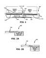
- FIG. 1is a representative side view of a mobile computing device constructed in accordance with an embodiment of the invention.
- FIG. 2Ais a side view of a display component for providing display area 120 , under an embodiment of the invention.
- FIG. 2Bis a side view of an alternative display component for providing the display area 120 , under another embodiment of the invention.
- FIG. 3Aillustrates a key structure layer for use in a keypad region, such as provided with the front face 102 of device 100 in FIG. 1 .
- FIG. 3Billustrates the electrical contact layer 334 that underlies the panel 150 , according to an embodiment such as shown by FIG. 1 .
- FIG. 4illustrates the panel 150 used for frontal assembly 110 , according to an embodiment of the invention.
- FIG. 5is a representative side view of a mobile computing device having an alternative construction in which a modular keypad component is used, according to an embodiment of the invention.
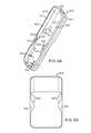
- FIG. 6A thru FIG. 6Gdepict a primary housing segment, under an embodiment of the invention.
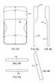
- FIG. 6Hdepicts a rear panel for use with a primary housing segment such as described in FIG. 6A thru FIG. 6G , under an embodiment.
- FIG. 7illustrates an integrated substrate module for use in assembling a computing device, according to an embodiment of the invention.
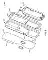
- FIG. 8is an exploded isometric view of a mobile computing device incorporating features of one or more embodiments described herein.
- Embodiments described hereinprovide for a mobile computing device constructed to include a panel on which a display area and a keypad are made available.
- the display areamay be provided flush on the panel.
- an embodimentprovides that the keypad assembly is molded or integrally formed onto the panel at another region.
- One result provided by an embodimentis relatively smooth and unifying front face for a mobile computing device, having a substantially flush display area and an integrally formed keypad.
- embodimentsrecognize that components such as keypads (or keyboards) and display components are increasingly manufactured by different sources and then assembled into one device. Tolerances resulting from the use and combination of different devices may conflict with the acceptable tolerance needed to assemble the device. Moreover, quality control issues arise to design and appearance of prominent exterior features, such as those provided with keypads, displays and the front facade.
- one or more embodimentsprovide for a front assembly that includes a panel that extends to encompass at least a substantial portion of the front face.
- the paneloverlays the display, while providing a surface on which a keypad or keyboard may be formed. The result is that a large portion of the front face may be made flush are bevel-less, without affect from possible conflicting tolerances that would otherwise result if no such panel existed.
- the panel that overlays the display componentmasks any deficiencies in the construction and/or assembly of the display component.
- one or more embodimentsfurther enable a single source of manufacturing to control the implementation and appearance of both the keypad and display on a front face of the computing device.
- a computing deviceincludes a processor, a display component, a keypad assembly and a panel.
- the display componentincludes a display area that is pressure-sensitive to detect user-contact with the device over the display area.
- the display componentis coupled to signal the processor when contact is detected.
- the keypad assemblyincludes a plurality of key structures. Each of the key structures is aligned over a corresponding contact element provided on an electrical contact layer. Each key structure is pressable, and the corresponding contact element of each key structure is triggerable with contact to signal the processor.
- the panelis provided over the display area to extend between the key structures and the electrical contact layer.
- the panelis structured so that, when the computing device is operational, (i) a user contact with a region of the panel that overlies the display area is detectable by the display component to signal the processor, and (ii) pressure on any key structure is sufficient to move at least a portion of the panel inward into the corresponding contact element in order to trigger the contact element into signaling the processor.
- a computing deviceincludes a processor, a display component, a keypad assembly and a panel.
- the display componentprovides or includes a display area.
- the keypad assemblyincludes a plurality of key structures. Each of the key structures may be aligned over a corresponding contact element provided on an electrical contact layer. Each key structure is pressable, and the corresponding contact element of each key structure is triggerable with contact to signal the processor.
- the panelmay be provided over the display area to extend between the key structures and the electrical contact layer.
- the panelmay include at least a translucent window that overlays the display area and is structured so that inward movement of any key structure is sufficient to move at least a portion of the panel inward into the corresponding contact element.
- the frontal assemblyincludes a display component, a keypad assembly, and a panel.
- the display componentincludes or provides a display area.
- the keypad assemblyincludes a plurality of key structures, and each of the key structures is aligned over a corresponding contact element provided on an underlying electrical contact layer. Each key structure is pressable.
- the panelmay provided over the display area to extend between the key structures and the electrical contact layer. The panel is structured to be in contact with the display area and with the plurality of key structures, so that movement of any key structure is sufficient to move at least a portion of the panel inward into the corresponding contact element.
- modulemeans a pre-assembled or pre-manufactured component.
- a modular componentfor example, means a component that is manufactured and used as one piece in a larger assembly.
- substantially flushmeans flushness between two surfaces to a degree that appears flush to casual viewing by an observer. For example, two surfaces that are flush within tolerance levels of manufacturing may be said to be “substantially flush”.
- An embodimentincludes a primary housing segment for a computing device.
- the primary housing segmentmay be unitarily formed and shaped to provide (i) at least a majority of a plurality of perimeter surfaces, the perimeter surfaces including a pair of opposing lateral surfaces, a bottom surface, and a top surface; (ii) one or more frontal surface regions; and (iii) a rear surface to retain an integrated substrate module.
- an embodimentprovides for a hardware module that includes a substrate, and a plurality of electrical components assembled onto the substrate.
- the plurality of electrical componentsmay include substantially all of the electrical components that are to be used by the computing device.
- the modulemay be integrated to form a single piece, so that a computing device that is to include the module is assembled in part by inserting the integrated substrate module as a single piece into a space within the confines of the primary housing segment.
- an embodimentprovides for a computing device that includes a housing comprising a primary housing segment, and interior components provided with use of an integrated substrate module.
- FIG. 1is a representative side view of a mobile computing device constructed in accordance with an embodiment of the invention.
- a mobile computing device 100includes a frontal assembly 110 that provides a front face 102 for the device 100 .
- the front face 102includes a display area 120 and a keypad region 130 .
- the display area 120may correspond to a surface provided by a display component such as described with an embodiment of FIG. 2A and FIG. 2B .
- the keypad region 130may correspond to a section of the front face 102 on which a keypad, such as a keyboard and/or number pad, is provided. Examples of different types of keypads that may be used to provide the keypad region 130 are described with embodiments of FIG. 3A , FIG. 3B and FIG. 5 .
- the frontal assembly 110includes a panel 150 that extends over the display region 120 and under the keypad area 130 .
- buttons set(not shown in FIG. 1 ) to control use and launch of software and software features, as well as enable navigation, may be provided between the display area 120 and the keypad region 130 .
- the mobile computing device 100may include various internal components, including processor 140 and memory 155 provided on a printed circuit board 160 .
- the processor 140may generate data that is displayed as content on the display area 120 , and detect and interpret input made through user-interaction with both the keypad region 130 and the display area 120 .
- Componentssuch as analog-digital converters may be used to process signals from display region and/or keypad assembly 130 . For simplicity, such additional components are not shown.
- the display region 120may be provided by a display component.
- the display componentis provided by a combination of a Liquid Crystal Display (LCD) 122 and contact-sensors 124 .
- the contact-sensors 124may correspond to, for example, resistive sensors that detect pressure from contact.
- the processor 140may detect and interpret contact made with the LCD 122 through signals generated from the contact-sensors.
- additional signal handling componentssuch as analog-digital converters, may also be used.
- the panel 150may be placed to provide an added exterior thickness to the display region 120 .
- the keypad region 130is provided by a keypad assembly that has anyone of many forms.
- the keypad assemblyis made operational with multiple layers, and the layers are separated by the panel 150 .
- An exterior layermay provide the keypad region 130 , comprising a thickness that defines plurality of key structures 132 .
- the layer of the key structures 132may operate in connection with an electrical contact layer 134 that underlies the panel 150 and the plurality of key structures 132 .
- the electrical contact layer 134may include contacts 335 ( FIG. 3B ) that are actuatable with contact or sufficient force.
- the panel 150may be attached to an underlying surface of the keypad structures 132 and to a top surface of the electrical contact layer 134 .
- the panel 150may have the form of a hard coat surface. As such, panel 150 provides a protective exterior for the display component.
- the panel 150is formed from polyethylene terephthalate (PET) film. More generally, the panel 150 may be formed from a material such as plastic. While the panel 150 may provide a protective hard coat, panel 150 may also be sufficiently thin so that inward pressure from one of the key structures 132 translates pressure through the panel 150 and onto the underlying electrical contact element 335 ( FIG. 3 ) for that structure.
- each key structure 132is aligned to include its own electrical contact element 335 , although other implementations provide that one electrical contact may be shared with different key structures.
- an embodiment such as described with FIG. 1enables device 100 to have a display region 120 that is bevel-less. More particularly, the display region 120 may be substantially flush with adjacent regions of the front face 102 that are not part of the display region 120 . Such a substantially flush transition protects the display component from, for example debris, while at the same time providing a more pleasing design. Additionally, the key structures 132 (or the layer thereof) may be formed directly on the panel 150 , simplifying construction and/or assembly of the device 100 as a whole. The panel 150 may also be provided with various design elements that include graphics for individual key structures.
- FIG. 1is illustrative, the thicknesses shown of various components are not to scale or proportion.
- the approximate thickness of panel 150is in the range of 0.1 to 0.3 mm, and more particularly at about 0.2 mm.
- FIG. 2Ais a side view of a display component for providing display area 120 , under an embodiment of the invention.
- a display component 200may include multiple thicknesses, generally including an LCD layer 210 and a sensor layer 220 . In some alternative implementations, the sensor layer 220 and LCD layer 210 may occupy the same thickness. More layers may be provided, including an exterior protective coat 230 . In one embodiment, the exterior protective coat 230 is provided by a portion of panel 150 that extends to support portions of the keyboard assembly 130 (not shown).
- the exterior protective coat 230may be formed from a combination of a thin thickness and a rigid backing material.
- the thin thicknessmay be provided by a material such as a PET film.
- An example of an approximate dimension of the PET filmis 0.2 mm.
- the rigid backing materialmay correspond to, for example, a polycarbonate material having an approximate thickness of about 1.0 mm.
- the polycarbonate material and the PET filmcombine at a region that overlays the display.
- the PET filmextends to form the remainder of the panel 150 on which, for example, key structures or a keypad are formed.
- the display component 200may interconnect with the processor 140 and other internal sources of the device 100 (such as power). In order to display content, display component 200 may be coupled to a display driver (not shown) and other components that process the display instructions.
- FIG. 2Bis a side view of an alternative display component for providing the display area 120 , under another embodiment of the invention.
- the display componentis modular, such as an over-the-shelf component.
- the display component 250includes multiple thicknesses, including an external hard coat display thickness 260 .
- the panel 150is mounted over the external display thickness 260 , so as to provide a second hard-coat layer.
- FIG. 1 and FIG. 2A and FIG. 2Bprovide for a contact-sensitive display
- one or more embodiments described hereinprovide for a construction in which the mobile computing device 100 includes a non-contact-sensitive display.
- the display component 200does not, incorporate the use of the sensor.
- FIG. 3Aillustrates a key structure layer for use in a keypad region, such as provided with the front face 102 of device 100 in FIG. 1 .
- a plurality of key structures 132FIG. 1
- the single piece structure 310overlays a portion of the panel 150 defined by the keypad region 130 .
- the plurality of key structures 132may be joined by a carrier 312 that extends between formations corresponding to individual key structures.
- the carrier 312may correspond to a base or web layer that interconnects some or all of the key structures.
- the key structure layer 310may be formed from resin, plastic or other material. In one embodiment, the key structure layer is translucent, so as to make visible any markings or decorative elements provided on the underlying panel 150 .
- the key structures 132are pressable in that they deform or squish when pushed. As an alternative or addition, however, the key structures 132 may move or travel inward when pressed.
- FIG. 3Billustrates the electrical contact layer 334 that underlies the panel 150 , according to an embodiment such as shown by FIG. 1 .
- An electrical contact layer 334such as shown in FIG. 3B may be used in connection with the key structure layer 310 to provide a keypad of the keypad region 130 ( FIG. 1 ).
- the electrical contact layer 334corresponds to a printed circuit board 320 having electrical contact elements 335 .
- the electrical contact elements 335may be in the form of electrical leads, snap dome switches or, for example, other elements that form “switches” having open and closed states.
- one electrical contact element 335is aligned under each key structure caps ( FIG. 3A ) of the key structure layer 310 ( FIG. 3A ).
- the panel 150may extend between the key structure layer 310 of FIG. 3A and the electrical contact layer 334 of FIG. 3B .
- the panel 150may be sufficiently thin to enable pressure applied to one of the key structures to translate into sufficient pressure or force to close the aligned electrical contact 335 ( FIG. 3B ).
- the key structures capsFIG. 3A
- the deformation of any one key structuremay provide the pressure onto the panel 150 that triggers the aligned contact element 335 ( FIG. 3B ) on the underlying PCB 320 .
- the key caps 332move inward
- the inward movement of any one key structuremay provide the pressure onto the panel 150 that triggers the corresponding aligned contact element 335 .
- the plurality of key structures 132( FIG. 1 ) is formed onto the panel 150 during a manufacturing process that results in the formation of key caps 332 and carrier 312 .
- injection molding design (IMD) or other molding techniquesmay be used to form key caps (as the key structures) directly on the panel 150 , or alternatively onto a carrier that is formed on the panel 150 .
- the plurality of key structures 132may be provided by assembling or affixing the structure 310 (or the key caps 332 ) onto the panel 150 .
- adhesivesmay be used to affix the carrier 312 and/or individual key caps 332 onto the panel 150 .
- panel 150may be imprinted to carry some or all of the graphics provided with the key structures 132 ( FIG. 1 ).
- individual key structuresmay be provided with graphics that indicate an alphanumeric value or icon.
- FIG. 4illustrates the panel 150 used for frontal assembly 110 , according to an embodiment of the invention.
- the panel 150may be dimensioned to be substantially rectangular so as to extend at least a majority of the length of the front face.
- the panel 150includes a clear (or translucent) window 410 and a backing portion 420 .
- the window 410may be dimensioned to substantially match an area used by thee display component 120 , so that it can overlay the display component (such as shown with an embodiment of FIG. 2A or FIG. 2B ) without occluding any part of the display region 120 .
- the backing portion 420provides the surface on which the plurality of key structures 132 ( FIG. 1 ) are formed or are otherwise provided.
- the backing portion 420 of panel 150may have imprints or graphics that form some or all of the key structure graphics.
- a first set of graphics 452may correspond to prints of letters and numbers in regions that are to underlay key structures 132 when the key structures are subsequently attached or formed on the panel.
- the graphics 452may be positioned in regions that underlie corresponding key structures 132 that are to carry that value when the device is in use.
- some key structurescarry letter values, number values or both.
- the graphics 452may represent key structure values in a specific mode of operation of the device (e.g. default mode), as logic and/or software on the device may assign other values to individual key structures.
- graphics 454may also be provided for a button (or key) set area of the device.
- a button setadjacent to the display area that includes navigation functionality, call action buttons (e.g. answer incoming call, hang-up), feature buttons for device or software control, and/or application launch buttons. Functionality associated with some or all of these buttons may be represented iconically, or otherwise through graphics.
- the set of graphics 454may be imprinted onto panel 150 to provide such iconinc graphics for buttons of such a button set.
- the devicemay carry both a wireless carrier brand and a manufacturing or device brand. Other brands may also be carried, such as a brand for the operating system in use on the device.
- FIG. 5is a representative side view of a mobile computing device having an alternative construction in which a modular keypad component is used, according to an embodiment of the invention.
- a modular keypad component 510may combine a layer of key structures and the electrical contact layer into one thickness that can be mounted onto the backing portion 420 ( FIG. 4 ) of the panel 150 .
- the modular keypad component 510may provide a keyboard (e.g. having a QWERTY arrangement) with, for example, alternative numerical assignments to select keys in order to enable corresponding numeric input (e.g. such as to place phone calls).
- a flex cable 515may interconnect the keypad component 510 to internal components of the device, including processing resources 140 and power (not shown).
- One or more embodimentsinclude a housing construction for a mobile computing device that includes a unitary primary housing element that provides a midframe, as well as at least some of a frontal housing and read housing.
- Embodiments described with FIG. 6A thru FIG. 8may be used with any of the embodiments described above. Alternatively, however, the housing construction shown and described with FIG. 6A thru FIG. 8 may be employed independently or without use of features included or provided as part of embodiments described above.
- a primary housing segmentis provided for a mobile computing device.
- the primary housing segmentmay be unitarily shaped to provide at least a majority of a pair of opposing lateral surfaces, a bottom surface, and/or a top surface.
- the primary housing segmentmay also be shaped to include one or more frontal structural surfaces that are positioned to retain an integrated substrate module or component of the computing device when the computing device is assembled. Additionally, the primary housing segment may be shaped to provide a rear structural surface to retain the integrated substrate module.
- FIG. 6Ais a front isometric view of a primary housing segment for use with a computing device, according to an embodiment of the invention.
- a primary housing segment 610is unitarily shaped to provide perimeter surfaces and surface regions for a front face 612 (defined by plane X 1 , Y 1 ) and a back face 614 (defined by plane X 2 , Y 2 ).
- the planes that define the front face 612 and back face 614may only be representative tangential planes, as the actual faces may be contoured or otherwise shaped/
- the front face 612may include one or more frontal surface regions 622 and an opening 625 or void.
- the opening 625may comprise a substantial portion of the front face 612 , so as to comprise a substantially open front face.
- the opening 625may comprise at least 60% of the front face, and in one implementation, the opening 625 may comprise 80 % or more of the front face.
- the front face 612may include an interior or inner perimeter edge 611 that defines the opening 625 of the front face.
- a surface thickness between the interior perimeter edge 611 and an exterior perimeter edge 613 of the primary housing segment 610may optionally provide some of the one or more frontal surface regions 622 .
- Such exterior surface thicknessmay be thin, such as in the form of a perimeter trim or bevel.
- the frontal surface regions 622include additional surface formations that can extend over some or all of the face 612 .
- such formationsmay correspond to a pair of polygonally-shaped (e.g. circular, oval, square or rectangular) sections 632 that extend inward from the interior perimeter edge 611 .
- Such frontal surface regionsmay provide structure or support to retain, for example, panel 150 ( FIG. 1 ) and/or an integrated substrate module 710 such as shown and described with an embodiment of FIG. 7A .
- an outward surface 621 of the sections 632also provide button or contact surfaces for enabling the user to manipulate the device.
- FIG. 6Aalso depicts an interior side 617 of a rear surface 624 that forms a portion of back face 614 .
- the back face 614may also include in opening 626 .
- the opening 626 of the back face 614may correspond to a partially open face, in that the opening of the back face is smaller than the opening 622 of the front face, occupying only a fraction or less than a majority of the back face.
- the opening 622may be dimensioned to receive a substrate, such as an integrated substrate module 710 , described with FIG. 7 .
- the opening 626is used in an assembly process to insert the integrated substrate module 710 (see FIG. 7A ) as part of an assembly process for the computing device.
- FIG. 6Bis a frontal view of the housing segment 610 , under an embodiment.
- the primary housing segment 610may include frontal surface regions 622 which extend to the polygonally-shaped sections 632 (which are shown to be rounded, inward extensions).
- the interior surface 617 of the back face 614 ( FIG. 6A )is also viewable through the opening 625 ( FIG. 6A ).
- the primary housing segment 610may be uniformly formed to provide the peripheral surfaces of the housing of the computing device.
- the primary housing segment 610may be shaped as part of a molding process to include peripheral surfaces at a top, bottom, and lateral sides, in addition to structure or surface that form at least a portion of the front face 612 and the back face 614 .
- FIG. 6Cis a rear view of the primary housing segment 610 , under an embodiment.
- An exterior side 619 of the rear face 624may form a portion of the shell that the user touches and grasps.
- the view presentedalso shows an interior side 633 to the polygonal extensions 632 that form portions of the frontal surface regions 622 .
- the interior side 633may abut, for example, the integrated substrate module 710 ( FIG. 7A ) when the device is assembled.
- the surrounding of the opening 626may be structured to receive and mate with a corresponding rear panel structure 660 (see FIG. 6H ).
- the rear panel structure 660may be a battery cover, or cover other components such as a SIM card. Any one of many conventional panel coupling techniques may be used.
- the rear panel structure 660may include protrusions that are received and mated with corresponding apertures of the back face 614 , while other mating surfaces on the back face 614 may receive the real panel structure 660 .
- FIG. 8illustrates how a suitable rear panel may be dimensioned and structured to mate with the primary housing segment 610 with an intermediate substrate device.
- FIG. 6D and FIG. 6Eare illustrative side-views of the primary housing segment 610 , under an embodiment.
- the primary housing segment 610may be shaped (e.g. such as through a molding process) to unitarily provide lateral perimeter surfaces 670 , 672 .
- the lateral perimeter surfaces 670 , 672may be used to define lateral edges of the device.
- the primary housing segment 610may form all, or at least a substantial majority of the lateral perimeter surfaces 670 , 672 .
- some openings or formationsmay be provided on one or both lateral perimeter surfaces 670 , 672 antennas, transmitters, buttons, switches or decor.
- FIG. 6Fillustrates a top perimeter surface 674 of the primary housing segment.
- FIG. 6Gillustrates a bottom peripheral surface 676 .
- Each of the top and bottom perimeter surfaces 674 , 676may be part of the shape of the unitary primary housing segment.
- the top and bottom perimeter surfaces 674 , 676may include openings, cut-outs or other formations to accommodate features such as antennas, transmitters, buttons, switches or decor.
- FIG. 7illustrates an integrated substrate module for use as part of a computing device, according to or more embodiments.
- the integrated substrate module 710is a pre-assembled, integrated component that contains substantially all of the electrical components and interconnects of a mobile computing device.
- the integrated substrate module 710may be assembled into a housing or housing segment as one piece.
- an integrated substrate moduleis operational in and of itself.
- the use of such the integrated substrate modulesimplifies the assembly process for a mobile computing device. Additionally, a mobile computing device may be tested without being assembled into a housing, thereby providing considerable time and labor savings during testing procedures that are normally required for manufacturing of such devices.
- the integrated substrate module 710includes a substrate 712 , such as a printed circuit board, that includes electrical interconnect (e.g. wiring, pins, traces) and a set of pre-mounted or pre-assembled electrical components.
- the set of pre-mounted or pre-assembled electrical componentsinclude substantially all of the devices electrical components, including the processors and memory components of the device, as a display component.
- the set of pre-mounted or pre-assembled electrical componentsmay also include other components, such as wireless transmitters and receivers and modems.
- electrical components provided on the integrated substrate module 710include a display component 722 and separate sets of contact elements 724 , 726 or switches for operating a multi-way or multi-state input features (e.g. such as navigation button to button set), application buttons and/or a keypad.
- the display component 722may correspond to, for example, an LCD or a touch-sensitive LCD.
- the integrated substrate module 710may also include a battery 732 , a chip set 734 containing the processor and memory for the device, speakers 736 , microphone 738 , camera 742 and switch 743 . In one embodiment, two sides of the integrated substrate module are used. In some variations, an element such as battery 732 may be provided separately from the integrated substrate module.
- the components of the integrated substrate module 710may be assembled in a separate manufacturing process. Under one embodiment, the integrated substrate module 710 may be manufactured and sold separately. The components that comprise the integrated substrate module 710 may be of a design specification. Likewise, dimensions (e.g. length or thickness) of the module may depend on manufacturing specifications, such as the desired form factor as provided by the housing of the device.
- the integrated substrate module 710may be assembled as part of the computing device that includes the primary housing segment 610 by inserting the substrate module in the opening 626 of the back face 614 . Some screws or other fasteners may be used to secure the substrate module to the housing.
- the integrated substrate moduleis created to be independently and fully functional prior to being assembled into a computing device.
- the integrated substrate modulemay be operated as part of a testing or design stage for the mobile computing device. If the integrated substrate module fails such tests or requirements of design, resources required to install and assembly a whole computing device are avoided. Rather, the electronic portion of the device may be designed and tested separately from the housing or design processes for forming the housing.
- FIG. 8is an exploded isometric view of a mobile computing device incorporating features of one or more embodiments described herein.
- a mobile computing device 800includes a panel 810 , a housing structure in form of a primary housing segment 820 , integrated substrate module 830 , and back panel 840 .
- the integrated substrate module 830includes a printed circuit board 832 with modularized display component 834 and electrical contact layer 836 for a keypad assembly.
- Numerous other internal components of device 800may be included on integrated substrate module 830 , including processing resources (not shown), memory resources (not shown), power (e.g. from on-board battery or external connection), and wireless communication components.
- the wireless communication componentsmay include both short range and long range components, including Bluetooth, cellular communications, Wireless Fidelity (or “WiFi”; i.e. 802.11(b) or 802.11(g)) communication components or Global Positioning System (GPS) devices.
- Bluetoothi.e. 802.11(b) or 802.11(g)
- WiFiWireless Fidelity
- GPSGlobal Positioning System
- an embodiment of FIG. 8reduces the number of housing elements used to create a mobile computing device (e.g. cellular phone) housing as compared to conventional designs. For example, some conventional techniques use a midframe that joins a front panel and a back panel. Often, devices include a fourth component to provide a backing for the battery panel. In contrast, an embodiment of FIG. 8 uses one shaped housing to eliminate need for the front panel, back panel or midframe of conventional designs. The back panel 840 may act as a battery panel.
- a mobile computing devicee.g. cellular phone
- the integrated substrate module 830is modularized, so as to be pre-assembled and usable as one piece when assembling the device 800 as a whole.
- the integrated substrate module 830may be inserted into the primary housing segment 820 .
- the primary housing segment 820may include front and structural features 822 , 824 that serve to retain the integrated substrate module 830 in place. Fasteners, adhesives or other suitable components may also be used to retain the integrated substrate module 830 in position.
- the panel 810may be placed over the integrated substrate module 830 and within the housing structure 820 . Unlike some other embodiments described, panel 810 is shaped to be non-rectangular, for purpose of design or style. Front structural features 822 may retain the panel 810 in position against the integrated substrate module 830 . A display region 812 of the panel 810 may overlap with the display component 834 provided on the integrated substrate module 830 . At least this portion of display region 812 may be clear or translucent so as to not occlude display component 834 .
- a key structure layer 814is molded, or otherwise formed or provided on a backing portion 816 of the panel 810 .
- the key structure layer 814overlaps with the electrical contact layer 836 on the integrated board 830 .
- the key structure layer 814may include deformable key elements that enable a user to apply discrete pressure to panel 810 , which translates into contact and actuation of individual contact elements on the electrical contact layer 836 .
- the display region 812may be substantially flush with surrounding non-display regions of the panel 810 . This enables the panel 810 to provide a relatively smooth and flat front face for the device 800 , without need for sunken or beveled display regions. Moreover, as described elsewhere, the key structure layer 814 may be formed on a corresponding region of the panel 810 .
- one or more embodimentsprovide for the following steps to be performed: (i) insertion of the integrated substrate module 830 into the primary housing segment 820 , with the direction of insertion being a top edge 831 of the board being moved into a bottom open region 821 of the housing structure; (ii) placement of the panel 810 over the integrated substrate module 830 ; and (iii) securement (via compression) of the back panel 840 against the primary housing segment 820 . Additional features, such as a navigation ring may be provided at any time. Housing screws or other fasteners may be used to retain the primary housing segment 820 with the integrated substrate module.
- FIG. 6A thru FIG. 6Gprovide for a single piece primary housing segment
- other embodimentsinclude multi-pieced housing segments.
- the primary housing segment 610( FIG. 6A ) may be formed from two pieces.
- the primary housing segment 610may be formed from a top shell and a bottom shell that combine together to provide features such as shown and described with the primary housing segment.
- the shellsmay be assembled to form openings on the front face and back face.
- the integrated substrate modulemay be inserted through the opening in a manner described with one or more other embodiments.
- a front face of a housing segmentsuch as described with any of the embodiments provided herein may include support frame structures to retain buttons or other mechanical actuators.
- the front facemay include a navigation input mechanism that includes one or more buttons. Structure from the primary (or from the two piece) housing segment may be used to retain the buttons that comprise such input feature. Similar housing structures may be used for application buttons and a keypad or keyboard.
Landscapes
- Engineering & Computer Science (AREA)
- Microelectronics & Electronic Packaging (AREA)
- Telephone Set Structure (AREA)
Abstract
Description
Claims (23)
Priority Applications (1)
| Application Number | Priority Date | Filing Date | Title |
|---|---|---|---|
| US11/948,741US8270158B2 (en) | 2007-08-30 | 2007-11-30 | Housing construction for mobile computing device |
Applications Claiming Priority (2)
| Application Number | Priority Date | Filing Date | Title |
|---|---|---|---|
| US11/848,184US20090058812A1 (en) | 2007-08-30 | 2007-08-30 | Mobile computing device construction using front paneled assembly and components thereof |
| US11/948,741US8270158B2 (en) | 2007-08-30 | 2007-11-30 | Housing construction for mobile computing device |
Related Parent Applications (1)
| Application Number | Title | Priority Date | Filing Date |
|---|---|---|---|
| US11/848,184Continuation-In-PartUS20090058812A1 (en) | 2007-08-30 | 2007-08-30 | Mobile computing device construction using front paneled assembly and components thereof |
Publications (2)
| Publication Number | Publication Date |
|---|---|
| US20090059495A1 US20090059495A1 (en) | 2009-03-05 |
| US8270158B2true US8270158B2 (en) | 2012-09-18 |
Family
ID=40407109
Family Applications (1)
| Application Number | Title | Priority Date | Filing Date |
|---|---|---|---|
| US11/948,741Active2031-03-19US8270158B2 (en) | 2007-08-30 | 2007-11-30 | Housing construction for mobile computing device |
Country Status (1)
| Country | Link |
|---|---|
| US (1) | US8270158B2 (en) |
Cited By (1)
| Publication number | Priority date | Publication date | Assignee | Title |
|---|---|---|---|---|
| US20130217444A1 (en)* | 2012-02-17 | 2013-08-22 | Lg Electronics Inc. | Mobile terminal |
Families Citing this family (22)
| Publication number | Priority date | Publication date | Assignee | Title |
|---|---|---|---|---|
| US9430074B2 (en) | 2008-01-04 | 2016-08-30 | Tactus Technology, Inc. | Dynamic tactile interface |
| US9588683B2 (en) | 2008-01-04 | 2017-03-07 | Tactus Technology, Inc. | Dynamic tactile interface |
| US9298261B2 (en) | 2008-01-04 | 2016-03-29 | Tactus Technology, Inc. | Method for actuating a tactile interface layer |
| US9612659B2 (en) | 2008-01-04 | 2017-04-04 | Tactus Technology, Inc. | User interface system |
| US9274612B2 (en) | 2008-01-04 | 2016-03-01 | Tactus Technology, Inc. | User interface system |
| US9552065B2 (en) | 2008-01-04 | 2017-01-24 | Tactus Technology, Inc. | Dynamic tactile interface |
| US20160187981A1 (en) | 2008-01-04 | 2016-06-30 | Tactus Technology, Inc. | Manual fluid actuator |
| US9423875B2 (en) | 2008-01-04 | 2016-08-23 | Tactus Technology, Inc. | Dynamic tactile interface with exhibiting optical dispersion characteristics |
| US9720501B2 (en) | 2008-01-04 | 2017-08-01 | Tactus Technology, Inc. | Dynamic tactile interface |
| US9063627B2 (en) | 2008-01-04 | 2015-06-23 | Tactus Technology, Inc. | User interface and methods |
| US9557915B2 (en) | 2008-01-04 | 2017-01-31 | Tactus Technology, Inc. | Dynamic tactile interface |
| US8947383B2 (en) | 2008-01-04 | 2015-02-03 | Tactus Technology, Inc. | User interface system and method |
| US9588684B2 (en) | 2009-01-05 | 2017-03-07 | Tactus Technology, Inc. | Tactile interface for a computing device |
| US9298262B2 (en) | 2010-01-05 | 2016-03-29 | Tactus Technology, Inc. | Dynamic tactile interface |
| WO2011112984A1 (en)* | 2010-03-11 | 2011-09-15 | Tactus Technology | User interface system |
| WO2011133605A1 (en) | 2010-04-19 | 2011-10-27 | Tactus Technology | Method of actuating a tactile interface layer |
| WO2011133604A1 (en) | 2010-04-19 | 2011-10-27 | Tactus Technology | User interface system |
| CN103124946B (en) | 2010-10-20 | 2016-06-29 | 泰克图斯科技公司 | User interface system and method |
| US8749962B2 (en)* | 2011-02-07 | 2014-06-10 | Qualcomm Incorporated | Keypad assembly with a contoured keypad facade for a mobile computing device |
| US9405417B2 (en) | 2012-09-24 | 2016-08-02 | Tactus Technology, Inc. | Dynamic tactile interface and methods |
| WO2014047656A2 (en) | 2012-09-24 | 2014-03-27 | Tactus Technology, Inc. | Dynamic tactile interface and methods |
| US9557813B2 (en) | 2013-06-28 | 2017-01-31 | Tactus Technology, Inc. | Method for reducing perceived optical distortion |
Citations (117)
| Publication number | Priority date | Publication date | Assignee | Title |
|---|---|---|---|---|
| US3744034A (en) | 1972-01-27 | 1973-07-03 | Perkin Elmer Corp | Method and apparatus for providing a security system for a computer |
| US4559705A (en) | 1983-11-25 | 1985-12-24 | Hodge Michaela W | Indexing overlay for video display devices |
| USD288746S (en) | 1984-03-12 | 1987-03-17 | Heinz Allekotte | Frame |
| US4860372A (en) | 1985-08-28 | 1989-08-22 | Hitachi, Ltd. | Real time handwritten character input system |
| USD306176S (en) | 1986-02-25 | 1990-02-20 | Sharp Corporation | Combined calculator and cradle therefor |
| US4916441A (en) | 1988-09-19 | 1990-04-10 | Clinicom Incorporated | Portable handheld terminal |
| US4927986A (en) | 1989-06-12 | 1990-05-22 | Grid Systems Corporation | Conductive stylus storage for a portable computer |
| US4972496A (en) | 1986-07-25 | 1990-11-20 | Grid Systems Corporation | Handwritten keyboardless entry computer system |
| US5040296A (en) | 1985-11-15 | 1991-08-20 | Wesco Ventures, Inc. | Erasable label |
| US5049862A (en) | 1989-10-06 | 1991-09-17 | Communication Intelligence Corporation ("Cic") | Keyless flat panel portable computer--computer aided notebook |
| USD326446S (en) | 1989-07-26 | 1992-05-26 | Wong Curtis G | Combined electronic book and CD ROM reader |
| US5128829A (en) | 1991-01-11 | 1992-07-07 | Health Innovations, Inc. | Hinge and stand for hand-held computer unit |
| US5165415A (en) | 1985-09-27 | 1992-11-24 | Bio-Rad Laboratories, Inc. | Self contained hand held ultrasonic instrument for ophthalmic use |
| US5205017A (en) | 1992-03-18 | 1993-04-27 | Jetta Computers Co., Ltd. | Notebook computer top cover mounting hardware |
| US5205107A (en) | 1992-05-27 | 1993-04-27 | Sheridan Lee Combs | Bag loading apparatus |
| US5231381A (en) | 1989-10-02 | 1993-07-27 | U.S. Philips Corp. | Data processing system with a touch screen and a digitizing tablet, both integrated in an input device |
| US5253142A (en) | 1991-09-19 | 1993-10-12 | Cal-Comp Electronics, Inc. | Body structure for a pocket computer having a fastener with multiple spaced apart elements |
| US5283862A (en) | 1989-10-11 | 1994-02-01 | Lund Alan K | Notebook computer with reversible cover for external use of membrane switch screen |
| US5305394A (en) | 1991-04-30 | 1994-04-19 | Sony Corporation | Character inputting apparatus |
| USD346591S (en) | 1991-12-17 | 1994-05-03 | Samsung Electronics Co., Ltd. | Portable pen computer |
| US5323291A (en) | 1992-10-15 | 1994-06-21 | Apple Computer, Inc. | Portable computer and docking station having an electromechanical docking/undocking mechanism and a plurality of cooperatively interacting failsafe mechanisms |
| USD355165S (en) | 1992-05-27 | 1995-02-07 | Sharp Kabushiki Kaisha | Portable computer with operation pen |
| USD355166S (en) | 1993-06-30 | 1995-02-07 | Sharp Kabushiki Kaisha | Electronic organizer |
| US5389745A (en) | 1991-09-11 | 1995-02-14 | Kabushiki Kaisha Toshiba | Handwriting input apparatus for inputting handwritten data from unspecified direction |
| US5398310A (en) | 1992-04-13 | 1995-03-14 | Apple Computer, Incorporated | Pointing gesture based computer note pad paging and scrolling interface |
| USD356550S (en) | 1993-06-14 | 1995-03-21 | Sharp Kabushiki Kaisha | Computer |
| US5401917A (en) | 1992-04-09 | 1995-03-28 | Sony Corporation | Input pen accommodation mechanism for tablet input apparatus |
| US5422442A (en) | 1992-10-30 | 1995-06-06 | Sharp Kabushiki Kaisha | Mechanism for containing input pen |
| US5430248A (en) | 1992-10-05 | 1995-07-04 | Thomas & Betts Corporation | Enclosure for an electrical terminal block including an improved enclosure cover |
| US5434929A (en) | 1994-07-12 | 1995-07-18 | Apple Computer, Inc. | Method and apparatus for setting character style preferences in a pen-based computer system |
| US5444192A (en) | 1993-07-01 | 1995-08-22 | Integral Information Systems | Interactive data entry apparatus |
| US5448433A (en) | 1990-12-19 | 1995-09-05 | Integral Peripherals | Disk drive information storage device with baseplate and cover having overlapping edge portions to provide protection from electromagnetic interference |
| US5452371A (en) | 1992-05-27 | 1995-09-19 | Apple Computer, Inc. | Method of aligning shapes on a display of a computer system |
| US5476336A (en) | 1995-03-06 | 1995-12-19 | Cullman Ventures, Inc. | Electronic organizer attachment for binder or book |
| USD366220S (en) | 1995-03-24 | 1996-01-16 | Matsushita Electric Industrial Co., Ltd. | Handheld position detecting and indicating receiver |
| USD366463S (en) | 1994-03-02 | 1996-01-23 | Apple Computer, Inc. | Handheld computer housing |
| US5489924A (en) | 1991-12-18 | 1996-02-06 | International Business Machines Corporation | Computer and display apparatus with input function |
| USD368079S (en) | 1994-03-02 | 1996-03-19 | Apple Computer, Inc. | Stylus for a handheld computer |
| US5506749A (en) | 1993-07-26 | 1996-04-09 | Kabushiki Kaisha Toshiba | Portable data-processing system having a removable battery pack replaceable with a second larger battery pack having a cylindrical member usable as a hand grip |
| US5528743A (en) | 1993-05-27 | 1996-06-18 | Apple Computer, Inc. | Method and apparatus for inserting text on a pen-based computer system |
| US5528746A (en) | 1992-10-31 | 1996-06-18 | Sony Corporation | Apparatus for controlling cassette auto changer |
| US5534892A (en) | 1992-05-20 | 1996-07-09 | Sharp Kabushiki Kaisha | Display-integrated type tablet device having and idle time in one display image frame to detect coordinates and having different electrode densities |
| US5548477A (en) | 1995-01-27 | 1996-08-20 | Khyber Technologies Corporation | Combination keyboard and cover for a handheld computer |
| US5550715A (en) | 1993-12-10 | 1996-08-27 | Palm Computing, Inc. | External light source for backlighting display |
| US5555157A (en) | 1994-03-02 | 1996-09-10 | Apple Computer, Inc. | Enclosure for electronic apparatus having a cover catch member engageable with two different housing catch members |
| US5564850A (en) | 1994-05-23 | 1996-10-15 | Pilot Precision Kabushiki Kaisha | Input pen with attached writing implement |
| US5576502A (en) | 1995-06-06 | 1996-11-19 | Wacom Co., Ltd. | Pointing unit and improved stylus pen |
| US5615284A (en) | 1993-11-29 | 1997-03-25 | International Business Machines Corporation | Stylus-input recognition correction manager computer program product |
| US5630148A (en) | 1994-06-17 | 1997-05-13 | Intel Corporation | Dynamic processor performance and power management in a computer system |
| US5635682A (en) | 1994-03-16 | 1997-06-03 | A.T. Cross Company | Wireless stylus and disposable stylus cartridge therefor for use with a pen computing device |
| US5646649A (en) | 1994-08-23 | 1997-07-08 | Mitsubishi Denki Kabushiki Kaisha | Portable information terminal |
| US5657459A (en) | 1992-09-11 | 1997-08-12 | Canon Kabushiki Kaisha | Data input pen-based information processing apparatus |
| USD385299S (en) | 1994-05-23 | 1997-10-21 | Adams Milton N | Electronic book |
| US5698822A (en) | 1994-05-16 | 1997-12-16 | Sharp Kabushiki Kaisha | Input and display apparatus for handwritten characters |
| US5737183A (en) | 1995-05-12 | 1998-04-07 | Ricoh Company, Ltd. | Compact portable computer having a riser that forms when a cover is opened |
| US5757681A (en) | 1995-06-14 | 1998-05-26 | Sharp Kabushiki Kaisha | Electronic apparatus with an input pen |
| US5786061A (en) | 1991-05-03 | 1998-07-28 | Velcro Industries B.V. | Separable fastener having a perimeter cover gasket |
| USD397679S (en) | 1996-11-04 | 1998-09-01 | Palm Computing, Inc. | Pocket-size organizer |
| US5810461A (en) | 1997-01-07 | 1998-09-22 | Apple Computer, Inc. | Methods and apparatus for organizing the electric cables of peripheral equipment attached to a computer housing |
| US5818182A (en) | 1993-08-13 | 1998-10-06 | Apple Computer, Inc. | Removable media ejection system |
| US5821510A (en) | 1994-12-22 | 1998-10-13 | Lucent Technologies Inc. | Labeling and tracing system for jumper used in an exchange |
| US5831613A (en) | 1997-01-06 | 1998-11-03 | Apple Computer, Inc. | Removable storage media stop/eject system for personal computers |
| US5841901A (en) | 1992-05-27 | 1998-11-24 | Hitachi, Ltd. | Pattern recognition system |
| US5848298A (en) | 1995-02-21 | 1998-12-08 | Intel Corporation | System having two PC cards in a hinged carrying case with battery compartment within in the hinge section |
| US5873372A (en) | 1995-08-02 | 1999-02-23 | Brown & Williamson Tobacco Corporation | Process for steam explosion of tobacco stem |
| US5889512A (en) | 1994-03-02 | 1999-03-30 | Apple Computer, Inc. | Extendible stylus |
| US5894425A (en) | 1997-02-28 | 1999-04-13 | Quantum Corporation | Wireless secondary interface for data storage device |
| USD408021S (en) | 1998-03-09 | 1999-04-13 | 3Com Corporation | Handheld computer |
| US5898568A (en) | 1997-07-25 | 1999-04-27 | Cheng; Chun-Cheng | External heat dissipator accessory for a notebook computer |
| USD410440S (en) | 1998-05-28 | 1999-06-01 | Charles F Carnell | Vehicle maintenance manager |
| US5914708A (en) | 1996-04-04 | 1999-06-22 | Cirque Corporation | Computer input stylus method and apparatus |
| US5913629A (en) | 1998-05-07 | 1999-06-22 | Ttools, Llc | Writing implement including an input stylus |
| USD411181S (en) | 1997-12-26 | 1999-06-22 | Sharp Kabushiki Kaisha | Electronic computer |
| USD411179S (en) | 1998-02-02 | 1999-06-22 | Xybernaut Coporation | Mobile body-worn computer |
| US5941648A (en) | 1998-10-21 | 1999-08-24 | Olivetti Office U.S.A., Inc. | Personal digital assistant having a foldable keyboard component |
| US5953205A (en) | 1996-10-11 | 1999-09-14 | Fujitsu Limited | Portable type information apparatus having a first housing with a display portion and a second housing movable to cover the first housing with a key in one, extending into a recess of the other, of the first and second housings |
| USD416001S (en) | 1998-10-30 | 1999-11-02 | 3 Com Corporation | Handheld computer device |
| US5999827A (en) | 1994-04-20 | 1999-12-07 | Sony Corporation | Communication terminal apparatus and control method thereof |
| US5996956A (en) | 1997-06-17 | 1999-12-07 | Shawver; Michael | Mounting platform for an electronic device |
| USD417657S (en) | 1997-10-16 | 1999-12-14 | Kabushiki Kaisha Toshiba | Portable information terminal unit |
| USD420987S (en) | 1998-11-18 | 2000-02-22 | Casio Keisanki Kabushiki Kaisha d.b.a. Casio Computer Co., Ltd. | Handheld computer |
| US6028765A (en) | 1997-06-19 | 2000-02-22 | Xplore Technologies, Inc. | Removable hand-grips for a portable pen-based computer |
| US6032866A (en) | 1997-09-10 | 2000-03-07 | Motorola, Inc. | Foldable apparatus having an interface |
| US6034685A (en) | 1995-02-24 | 2000-03-07 | Casio Computer Co., Ltd. | Data inputting devices |
| USD422271S (en) | 1998-07-29 | 2000-04-04 | Canon Kabushiki Kaisha | Portable computer with data communication function |
| US6052279A (en) | 1996-12-05 | 2000-04-18 | Intermec Ip Corp. | Customizable hand-held computer |
| USD423468S (en) | 1999-02-08 | 2000-04-25 | Symbol Technologies, Inc. | Hand-held pen terminal |
| USD424535S (en) | 1999-06-02 | 2000-05-09 | Oy Hi-Log Instruments Ltd. | Data terminal for replies from customers |
| USD424533S (en) | 1998-11-06 | 2000-05-09 | Dauphin Technology, Inc. | Hand held computer |
| USD426236S (en) | 1998-09-21 | 2000-06-06 | Ideo Product Development, Inc. | Detachable case |
| US6102721A (en) | 1995-06-20 | 2000-08-15 | Kabushiki Kaisha Toshiba | Portable apparatus having ejector for ejecting a unit stored in the receptacle |
| US6115248A (en) | 1999-05-17 | 2000-09-05 | Palm, Inc. | Detachable securement of an accessory device to a handheld computer |
| US6178087B1 (en) | 1997-10-13 | 2001-01-23 | Samsung Electronics Co. Ltd. | Multimedia apparatus using a portable computer |
| US6195589B1 (en) | 1998-03-09 | 2001-02-27 | 3Com Corporation | Personal data assistant with remote control capabilities |
| USD440542S1 (en) | 1996-11-04 | 2001-04-17 | Palm Computing, Inc. | Pocket-size organizer with stand |
| US6219256B1 (en) | 1997-10-21 | 2001-04-17 | Hon Hai Precision Ind. Co., Ltd. | Card adapter interfacing between a card connector and a memory card |
| US6239968B1 (en) | 1998-12-21 | 2001-05-29 | Ideo Product Development Inc. | Detachable case for an electronic organizer |
| USD456289S1 (en) | 2001-07-05 | 2002-04-30 | Garmin Ltd. | Electronic navigation instrument |
| US6392639B1 (en) | 1998-03-31 | 2002-05-21 | Samsung Electronics, Co., Ltd. | Palm-sized computer with a stylus holding arrangement |
| USD466504S1 (en) | 2001-06-19 | 2002-12-03 | Nec Corporation | Portable wireless terminal equipment |
| USD467918S1 (en) | 2001-04-24 | 2002-12-31 | Hand Held Products, Inc. | Data collection device |
| USD469061S1 (en) | 2002-02-19 | 2003-01-21 | Arthur James Porter | Key chain mountable battery holder in the shape of a generic personal digital assistant |
| US20030157957A1 (en) | 2002-02-19 | 2003-08-21 | Wendorff John J. | Data phone with convertible keypad and method of using same |
| USD488162S1 (en) | 2003-05-12 | 2004-04-06 | James Korpai | Screen border |
| US6842335B1 (en) | 2001-11-21 | 2005-01-11 | Palmone, Inc. | Multifunctional cover integrated into sub-panel of portable electronic device |
| USD502703S1 (en) | 2004-04-05 | 2005-03-08 | Sharp Kabushiki Kaisha | Personal digital assistant |
| USD511342S1 (en) | 2004-08-04 | 2005-11-08 | High Tech Computer, Corp. | Handheld electronic device |
| US20050264988A1 (en)* | 2004-05-26 | 2005-12-01 | Nicolosi Matthew T | Slide case with pivotable stand member for handheld computing device |
| USD530698S1 (en) | 2005-04-27 | 2006-10-24 | Samsung Electronics Co., Ltd. | Mobile phone |
| USD532440S1 (en) | 2005-05-06 | 2006-11-21 | Calibre International, Llc | Calculator |
| US20060265643A1 (en) | 2005-05-17 | 2006-11-23 | Keith Saft | Optimal viewing of digital images and voice annotation transitions in slideshows |
| US20070074957A1 (en) | 2005-09-30 | 2007-04-05 | Lawrence Lam | Switch assembly having non-planar surface and activation areas |
| US20070081303A1 (en)* | 2005-10-11 | 2007-04-12 | Lawrence Lam | Recess housing feature for computing devices |
| US7205959B2 (en) | 2003-09-09 | 2007-04-17 | Sony Ericsson Mobile Communications Ab | Multi-layered displays providing different focal lengths with optically shiftable viewing formats and terminals incorporating the same |
| US7231208B2 (en) | 2001-10-17 | 2007-06-12 | Palm, Inc. | User interface-technique for managing an active call |
| USD548732S1 (en) | 2005-04-22 | 2007-08-14 | Palm, Inc. | Front panel of a housing for a portable computing device |
| US20090058819A1 (en)* | 2007-08-31 | 2009-03-05 | Richard Gioscia | Soft-user interface feature provided in combination with pressable display surface |
Family Cites Families (3)
| Publication number | Priority date | Publication date | Assignee | Title |
|---|---|---|---|---|
| USD355164S (en)* | 1993-05-19 | 1995-02-07 | Shen Wei H | Flexible lighting fixture mounting track |
| US5791673A (en)* | 1996-05-22 | 1998-08-11 | Cannondale Corporation | Frame having a central backbone and opposing skins |
| USD420687S (en)* | 1998-12-22 | 2000-02-15 | Ken Dragon | Angled wood holder for table saws |
- 2007
- 2007-11-30USUS11/948,741patent/US8270158B2/enactiveActive
Patent Citations (121)
| Publication number | Priority date | Publication date | Assignee | Title |
|---|---|---|---|---|
| US3744034A (en) | 1972-01-27 | 1973-07-03 | Perkin Elmer Corp | Method and apparatus for providing a security system for a computer |
| US4559705A (en) | 1983-11-25 | 1985-12-24 | Hodge Michaela W | Indexing overlay for video display devices |
| USD288746S (en) | 1984-03-12 | 1987-03-17 | Heinz Allekotte | Frame |
| US4860372A (en) | 1985-08-28 | 1989-08-22 | Hitachi, Ltd. | Real time handwritten character input system |
| US5165415A (en) | 1985-09-27 | 1992-11-24 | Bio-Rad Laboratories, Inc. | Self contained hand held ultrasonic instrument for ophthalmic use |
| US5040296A (en) | 1985-11-15 | 1991-08-20 | Wesco Ventures, Inc. | Erasable label |
| USD306176S (en) | 1986-02-25 | 1990-02-20 | Sharp Corporation | Combined calculator and cradle therefor |
| US4972496A (en) | 1986-07-25 | 1990-11-20 | Grid Systems Corporation | Handwritten keyboardless entry computer system |
| US4916441A (en) | 1988-09-19 | 1990-04-10 | Clinicom Incorporated | Portable handheld terminal |
| US4927986A (en) | 1989-06-12 | 1990-05-22 | Grid Systems Corporation | Conductive stylus storage for a portable computer |
| USD326446S (en) | 1989-07-26 | 1992-05-26 | Wong Curtis G | Combined electronic book and CD ROM reader |
| US5231381A (en) | 1989-10-02 | 1993-07-27 | U.S. Philips Corp. | Data processing system with a touch screen and a digitizing tablet, both integrated in an input device |
| US5049862A (en) | 1989-10-06 | 1991-09-17 | Communication Intelligence Corporation ("Cic") | Keyless flat panel portable computer--computer aided notebook |
| US5283862A (en) | 1989-10-11 | 1994-02-01 | Lund Alan K | Notebook computer with reversible cover for external use of membrane switch screen |
| US5448433A (en) | 1990-12-19 | 1995-09-05 | Integral Peripherals | Disk drive information storage device with baseplate and cover having overlapping edge portions to provide protection from electromagnetic interference |
| US5128829A (en) | 1991-01-11 | 1992-07-07 | Health Innovations, Inc. | Hinge and stand for hand-held computer unit |
| US5305394A (en) | 1991-04-30 | 1994-04-19 | Sony Corporation | Character inputting apparatus |
| US5942177A (en) | 1991-05-03 | 1999-08-24 | Velcro Industies B.V. | Method for a making a separable fastener having a perimeter cover gasket |
| US5786061A (en) | 1991-05-03 | 1998-07-28 | Velcro Industries B.V. | Separable fastener having a perimeter cover gasket |
| US5389745A (en) | 1991-09-11 | 1995-02-14 | Kabushiki Kaisha Toshiba | Handwriting input apparatus for inputting handwritten data from unspecified direction |
| US5253142A (en) | 1991-09-19 | 1993-10-12 | Cal-Comp Electronics, Inc. | Body structure for a pocket computer having a fastener with multiple spaced apart elements |
| USD346591S (en) | 1991-12-17 | 1994-05-03 | Samsung Electronics Co., Ltd. | Portable pen computer |
| US5489924A (en) | 1991-12-18 | 1996-02-06 | International Business Machines Corporation | Computer and display apparatus with input function |
| US5205017A (en) | 1992-03-18 | 1993-04-27 | Jetta Computers Co., Ltd. | Notebook computer top cover mounting hardware |
| US5401917A (en) | 1992-04-09 | 1995-03-28 | Sony Corporation | Input pen accommodation mechanism for tablet input apparatus |
| US5398310A (en) | 1992-04-13 | 1995-03-14 | Apple Computer, Incorporated | Pointing gesture based computer note pad paging and scrolling interface |
| US5534892A (en) | 1992-05-20 | 1996-07-09 | Sharp Kabushiki Kaisha | Display-integrated type tablet device having and idle time in one display image frame to detect coordinates and having different electrode densities |
| USD355165S (en) | 1992-05-27 | 1995-02-07 | Sharp Kabushiki Kaisha | Portable computer with operation pen |
| US5621817A (en) | 1992-05-27 | 1997-04-15 | Apple Computer, Inc. | Pointer-based computer system capable of aligning geometric figures |
| US5841901A (en) | 1992-05-27 | 1998-11-24 | Hitachi, Ltd. | Pattern recognition system |
| US5205107A (en) | 1992-05-27 | 1993-04-27 | Sheridan Lee Combs | Bag loading apparatus |
| US5452371A (en) | 1992-05-27 | 1995-09-19 | Apple Computer, Inc. | Method of aligning shapes on a display of a computer system |
| US5657459A (en) | 1992-09-11 | 1997-08-12 | Canon Kabushiki Kaisha | Data input pen-based information processing apparatus |
| US5430248A (en) | 1992-10-05 | 1995-07-04 | Thomas & Betts Corporation | Enclosure for an electrical terminal block including an improved enclosure cover |
| US5323291A (en) | 1992-10-15 | 1994-06-21 | Apple Computer, Inc. | Portable computer and docking station having an electromechanical docking/undocking mechanism and a plurality of cooperatively interacting failsafe mechanisms |
| US5422442A (en) | 1992-10-30 | 1995-06-06 | Sharp Kabushiki Kaisha | Mechanism for containing input pen |
| US5528746A (en) | 1992-10-31 | 1996-06-18 | Sony Corporation | Apparatus for controlling cassette auto changer |
| US5528743A (en) | 1993-05-27 | 1996-06-18 | Apple Computer, Inc. | Method and apparatus for inserting text on a pen-based computer system |
| USD356550S (en) | 1993-06-14 | 1995-03-21 | Sharp Kabushiki Kaisha | Computer |
| USD355166S (en) | 1993-06-30 | 1995-02-07 | Sharp Kabushiki Kaisha | Electronic organizer |
| US5444192A (en) | 1993-07-01 | 1995-08-22 | Integral Information Systems | Interactive data entry apparatus |
| US5506749A (en) | 1993-07-26 | 1996-04-09 | Kabushiki Kaisha Toshiba | Portable data-processing system having a removable battery pack replaceable with a second larger battery pack having a cylindrical member usable as a hand grip |
| US5818182A (en) | 1993-08-13 | 1998-10-06 | Apple Computer, Inc. | Removable media ejection system |
| US5615284A (en) | 1993-11-29 | 1997-03-25 | International Business Machines Corporation | Stylus-input recognition correction manager computer program product |
| US5550715A (en) | 1993-12-10 | 1996-08-27 | Palm Computing, Inc. | External light source for backlighting display |
| US5555157A (en) | 1994-03-02 | 1996-09-10 | Apple Computer, Inc. | Enclosure for electronic apparatus having a cover catch member engageable with two different housing catch members |
| USD368079S (en) | 1994-03-02 | 1996-03-19 | Apple Computer, Inc. | Stylus for a handheld computer |
| US5889512A (en) | 1994-03-02 | 1999-03-30 | Apple Computer, Inc. | Extendible stylus |
| USD366463S (en) | 1994-03-02 | 1996-01-23 | Apple Computer, Inc. | Handheld computer housing |
| US5635682A (en) | 1994-03-16 | 1997-06-03 | A.T. Cross Company | Wireless stylus and disposable stylus cartridge therefor for use with a pen computing device |
| US5999827A (en) | 1994-04-20 | 1999-12-07 | Sony Corporation | Communication terminal apparatus and control method thereof |
| US5698822A (en) | 1994-05-16 | 1997-12-16 | Sharp Kabushiki Kaisha | Input and display apparatus for handwritten characters |
| US5564850A (en) | 1994-05-23 | 1996-10-15 | Pilot Precision Kabushiki Kaisha | Input pen with attached writing implement |
| USD385299S (en) | 1994-05-23 | 1997-10-21 | Adams Milton N | Electronic book |
| US5630148A (en) | 1994-06-17 | 1997-05-13 | Intel Corporation | Dynamic processor performance and power management in a computer system |
| US5434929A (en) | 1994-07-12 | 1995-07-18 | Apple Computer, Inc. | Method and apparatus for setting character style preferences in a pen-based computer system |
| US5646649A (en) | 1994-08-23 | 1997-07-08 | Mitsubishi Denki Kabushiki Kaisha | Portable information terminal |
| US5821510A (en) | 1994-12-22 | 1998-10-13 | Lucent Technologies Inc. | Labeling and tracing system for jumper used in an exchange |
| US5548477A (en) | 1995-01-27 | 1996-08-20 | Khyber Technologies Corporation | Combination keyboard and cover for a handheld computer |
| US5638257A (en) | 1995-01-27 | 1997-06-10 | Khyber Technologies Corporation | Combination keyboard and cover for a handheld computer |
| US5848298A (en) | 1995-02-21 | 1998-12-08 | Intel Corporation | System having two PC cards in a hinged carrying case with battery compartment within in the hinge section |
| US6034685A (en) | 1995-02-24 | 2000-03-07 | Casio Computer Co., Ltd. | Data inputting devices |
| US5476336A (en) | 1995-03-06 | 1995-12-19 | Cullman Ventures, Inc. | Electronic organizer attachment for binder or book |
| USD366220S (en) | 1995-03-24 | 1996-01-16 | Matsushita Electric Industrial Co., Ltd. | Handheld position detecting and indicating receiver |
| US5737183A (en) | 1995-05-12 | 1998-04-07 | Ricoh Company, Ltd. | Compact portable computer having a riser that forms when a cover is opened |
| US5576502A (en) | 1995-06-06 | 1996-11-19 | Wacom Co., Ltd. | Pointing unit and improved stylus pen |
| US5757681A (en) | 1995-06-14 | 1998-05-26 | Sharp Kabushiki Kaisha | Electronic apparatus with an input pen |
| US6102721A (en) | 1995-06-20 | 2000-08-15 | Kabushiki Kaisha Toshiba | Portable apparatus having ejector for ejecting a unit stored in the receptacle |
| US5873372A (en) | 1995-08-02 | 1999-02-23 | Brown & Williamson Tobacco Corporation | Process for steam explosion of tobacco stem |
| US5914708A (en) | 1996-04-04 | 1999-06-22 | Cirque Corporation | Computer input stylus method and apparatus |
| US5953205A (en) | 1996-10-11 | 1999-09-14 | Fujitsu Limited | Portable type information apparatus having a first housing with a display portion and a second housing movable to cover the first housing with a key in one, extending into a recess of the other, of the first and second housings |
| USD397679S (en) | 1996-11-04 | 1998-09-01 | Palm Computing, Inc. | Pocket-size organizer |
| USD440542S1 (en) | 1996-11-04 | 2001-04-17 | Palm Computing, Inc. | Pocket-size organizer with stand |
| US6052279A (en) | 1996-12-05 | 2000-04-18 | Intermec Ip Corp. | Customizable hand-held computer |
| US5831613A (en) | 1997-01-06 | 1998-11-03 | Apple Computer, Inc. | Removable storage media stop/eject system for personal computers |
| US5810461A (en) | 1997-01-07 | 1998-09-22 | Apple Computer, Inc. | Methods and apparatus for organizing the electric cables of peripheral equipment attached to a computer housing |
| US5894425A (en) | 1997-02-28 | 1999-04-13 | Quantum Corporation | Wireless secondary interface for data storage device |
| US5996956A (en) | 1997-06-17 | 1999-12-07 | Shawver; Michael | Mounting platform for an electronic device |
| US6028765A (en) | 1997-06-19 | 2000-02-22 | Xplore Technologies, Inc. | Removable hand-grips for a portable pen-based computer |
| US5898568A (en) | 1997-07-25 | 1999-04-27 | Cheng; Chun-Cheng | External heat dissipator accessory for a notebook computer |
| US6032866A (en) | 1997-09-10 | 2000-03-07 | Motorola, Inc. | Foldable apparatus having an interface |
| US6178087B1 (en) | 1997-10-13 | 2001-01-23 | Samsung Electronics Co. Ltd. | Multimedia apparatus using a portable computer |
| USD417657S (en) | 1997-10-16 | 1999-12-14 | Kabushiki Kaisha Toshiba | Portable information terminal unit |
| US6219256B1 (en) | 1997-10-21 | 2001-04-17 | Hon Hai Precision Ind. Co., Ltd. | Card adapter interfacing between a card connector and a memory card |
| USD411181S (en) | 1997-12-26 | 1999-06-22 | Sharp Kabushiki Kaisha | Electronic computer |
| USD411179S (en) | 1998-02-02 | 1999-06-22 | Xybernaut Coporation | Mobile body-worn computer |
| USD408021S (en) | 1998-03-09 | 1999-04-13 | 3Com Corporation | Handheld computer |
| US6195589B1 (en) | 1998-03-09 | 2001-02-27 | 3Com Corporation | Personal data assistant with remote control capabilities |
| US6392639B1 (en) | 1998-03-31 | 2002-05-21 | Samsung Electronics, Co., Ltd. | Palm-sized computer with a stylus holding arrangement |
| US5913629A (en) | 1998-05-07 | 1999-06-22 | Ttools, Llc | Writing implement including an input stylus |
| USD410440S (en) | 1998-05-28 | 1999-06-01 | Charles F Carnell | Vehicle maintenance manager |
| USD422271S (en) | 1998-07-29 | 2000-04-04 | Canon Kabushiki Kaisha | Portable computer with data communication function |
| USD436963S1 (en) | 1998-09-21 | 2001-01-30 | Ideo Product Development Inc. | Detachable case attachment rail |
| USD426236S (en) | 1998-09-21 | 2000-06-06 | Ideo Product Development, Inc. | Detachable case |
| US5941648A (en) | 1998-10-21 | 1999-08-24 | Olivetti Office U.S.A., Inc. | Personal digital assistant having a foldable keyboard component |
| USD416001S (en) | 1998-10-30 | 1999-11-02 | 3 Com Corporation | Handheld computer device |
| USD424533S (en) | 1998-11-06 | 2000-05-09 | Dauphin Technology, Inc. | Hand held computer |
| USD420987S (en) | 1998-11-18 | 2000-02-22 | Casio Keisanki Kabushiki Kaisha d.b.a. Casio Computer Co., Ltd. | Handheld computer |
| US6239968B1 (en) | 1998-12-21 | 2001-05-29 | Ideo Product Development Inc. | Detachable case for an electronic organizer |
| USD423468S (en) | 1999-02-08 | 2000-04-25 | Symbol Technologies, Inc. | Hand-held pen terminal |
| US6115248A (en) | 1999-05-17 | 2000-09-05 | Palm, Inc. | Detachable securement of an accessory device to a handheld computer |
| USD424535S (en) | 1999-06-02 | 2000-05-09 | Oy Hi-Log Instruments Ltd. | Data terminal for replies from customers |
| USD467918S1 (en) | 2001-04-24 | 2002-12-31 | Hand Held Products, Inc. | Data collection device |
| USD466504S1 (en) | 2001-06-19 | 2002-12-03 | Nec Corporation | Portable wireless terminal equipment |
| USD456289S1 (en) | 2001-07-05 | 2002-04-30 | Garmin Ltd. | Electronic navigation instrument |
| US7231208B2 (en) | 2001-10-17 | 2007-06-12 | Palm, Inc. | User interface-technique for managing an active call |
| US6842335B1 (en) | 2001-11-21 | 2005-01-11 | Palmone, Inc. | Multifunctional cover integrated into sub-panel of portable electronic device |
| USD469061S1 (en) | 2002-02-19 | 2003-01-21 | Arthur James Porter | Key chain mountable battery holder in the shape of a generic personal digital assistant |
| US20030157957A1 (en) | 2002-02-19 | 2003-08-21 | Wendorff John J. | Data phone with convertible keypad and method of using same |
| USD488162S1 (en) | 2003-05-12 | 2004-04-06 | James Korpai | Screen border |
| US7205959B2 (en) | 2003-09-09 | 2007-04-17 | Sony Ericsson Mobile Communications Ab | Multi-layered displays providing different focal lengths with optically shiftable viewing formats and terminals incorporating the same |
| USD502703S1 (en) | 2004-04-05 | 2005-03-08 | Sharp Kabushiki Kaisha | Personal digital assistant |
| US20050264988A1 (en)* | 2004-05-26 | 2005-12-01 | Nicolosi Matthew T | Slide case with pivotable stand member for handheld computing device |
| USD511342S1 (en) | 2004-08-04 | 2005-11-08 | High Tech Computer, Corp. | Handheld electronic device |
| USD548732S1 (en) | 2005-04-22 | 2007-08-14 | Palm, Inc. | Front panel of a housing for a portable computing device |
| USD530698S1 (en) | 2005-04-27 | 2006-10-24 | Samsung Electronics Co., Ltd. | Mobile phone |
| USD532440S1 (en) | 2005-05-06 | 2006-11-21 | Calibre International, Llc | Calculator |
| US20060265643A1 (en) | 2005-05-17 | 2006-11-23 | Keith Saft | Optimal viewing of digital images and voice annotation transitions in slideshows |
| US20070074957A1 (en) | 2005-09-30 | 2007-04-05 | Lawrence Lam | Switch assembly having non-planar surface and activation areas |
| US20070081303A1 (en)* | 2005-10-11 | 2007-04-12 | Lawrence Lam | Recess housing feature for computing devices |
| US20090058819A1 (en)* | 2007-08-31 | 2009-03-05 | Richard Gioscia | Soft-user interface feature provided in combination with pressable display surface |
Non-Patent Citations (2)
| Title |
|---|
| International Search Report and Written Opinion of the International Searching Authority in International Application PCT/US2006/038790, European Patent Office, Oct. 24, 2007, 18 pgs. |
| Palm LifeDrive Quicktrain.qxd, Dec. 6, 2005, (3 pgs). |
Cited By (2)
| Publication number | Priority date | Publication date | Assignee | Title |
|---|---|---|---|---|
| US20130217444A1 (en)* | 2012-02-17 | 2013-08-22 | Lg Electronics Inc. | Mobile terminal |
| US8880129B2 (en)* | 2012-02-17 | 2014-11-04 | Lg Electronics Inc. | Mobile terminal |
Also Published As
| Publication number | Publication date |
|---|---|
| US20090059495A1 (en) | 2009-03-05 |
Similar Documents
| Publication | Publication Date | Title |
|---|---|---|
| US8270158B2 (en) | Housing construction for mobile computing device | |
| KR101050030B1 (en) | Electronics | |
| KR101020464B1 (en) | Electronics | |
| US8284164B2 (en) | Touch input device | |
| US20160320810A1 (en) | Cover and electronic device including the same | |
| US7375721B2 (en) | Keyboard with changeable key display | |
| US20120289294A1 (en) | Mobile terminal | |
| JP2008052606A (en) | Electronics | |
| JP4767792B2 (en) | Electronics | |
| US8576552B2 (en) | Display assembly for a computing device | |
| CA2694574A1 (en) | A key assembly for a handheld electronic device having a one-piece keycap | |
| US20090058812A1 (en) | Mobile computing device construction using front paneled assembly and components thereof | |
| EP2535914B1 (en) | Key lighting assembly | |
| CA2765693C (en) | Electronic mobile device seamless key/display structure | |
| US9092192B2 (en) | Electronic mobile device seamless key/display structure | |
| US9126484B2 (en) | Method for manufacturing a human-machine interface for a motor vehicle, and human-machine interface produced by said method | |
| JP4767793B2 (en) | Electronics | |
| EP2487880B1 (en) | Electronic mobile device having a keypad assembly with a film overlay | |
| EP2595366A1 (en) | Touch tracking optical input device | |
| US20190079618A1 (en) | Touch panel device | |
| KR101960513B1 (en) | Mobile terminal | |
| US20120208590A1 (en) | Electronic mobile device having a keypad assembly with a film overlay | |
| JP2008136046A (en) | Electronics | |
| US8749962B2 (en) | Keypad assembly with a contoured keypad facade for a mobile computing device | |
| KR20090130776A (en) | Case integrated touch panel of electronic device |
Legal Events
| Date | Code | Title | Description |
|---|---|---|---|
| AS | Assignment | Owner name:PALM, INC., CALIFORNIA Free format text:ASSIGNMENT OF ASSIGNORS INTEREST;ASSIGNOR:MATSUOKA, YOSHIMICHI;REEL/FRAME:020183/0271 Effective date:20071129 | |
| AS | Assignment | Owner name:JPMORGAN CHASE BANK, N.A., AS ADMINISTRATIVE AGENT Free format text:SECURITY AGREEMENT;ASSIGNOR:PALM, INC.;REEL/FRAME:020432/0987 Effective date:20080125 | |
| AS | Assignment | Owner name:PALM, INC., CALIFORNIA Free format text:RELEASE BY SECURED PARTY;ASSIGNOR:JPMORGAN CHASE BANK, N.A., AS ADMINISTRATIVE AGENT;REEL/FRAME:024630/0474 Effective date:20100701 | |
| AS | Assignment | Owner name:HEWLETT-PACKARD DEVELOPMENT COMPANY, L.P., TEXAS Free format text:ASSIGNMENT OF ASSIGNORS INTEREST;ASSIGNOR:PALM, INC.;REEL/FRAME:025204/0809 Effective date:20101027 | |
| STCF | Information on status: patent grant | Free format text:PATENTED CASE | |
| AS | Assignment | Owner name:PALM, INC., CALIFORNIA Free format text:ASSIGNMENT OF ASSIGNORS INTEREST;ASSIGNOR:HEWLETT-PACKARD DEVELOPMENT COMPANY, L.P.;REEL/FRAME:030341/0459 Effective date:20130430 | |
| FEPP | Fee payment procedure | Free format text:PAYOR NUMBER ASSIGNED (ORIGINAL EVENT CODE: ASPN); ENTITY STATUS OF PATENT OWNER: LARGE ENTITY | |
| AS | Assignment | Owner name:PALM, INC., CALIFORNIA Free format text:ASSIGNMENT OF ASSIGNORS INTEREST;ASSIGNOR:HEWLETT-PACKARD DEVELOPMENT COMPANY, L.P.;REEL/FRAME:031837/0544 Effective date:20131218 Owner name:HEWLETT-PACKARD DEVELOPMENT COMPANY, L.P., TEXAS Free format text:ASSIGNMENT OF ASSIGNORS INTEREST;ASSIGNOR:PALM, INC.;REEL/FRAME:031837/0659 Effective date:20131218 Owner name:HEWLETT-PACKARD DEVELOPMENT COMPANY, L.P., TEXAS Free format text:ASSIGNMENT OF ASSIGNORS INTEREST;ASSIGNOR:PALM, INC.;REEL/FRAME:031837/0239 Effective date:20131218 | |
| AS | Assignment | Owner name:QUALCOMM INCORPORATED, CALIFORNIA Free format text:ASSIGNMENT OF ASSIGNORS INTEREST;ASSIGNORS:HEWLETT-PACKARD COMPANY;HEWLETT-PACKARD DEVELOPMENT COMPANY, L.P.;PALM, INC.;REEL/FRAME:032132/0001 Effective date:20140123 | |
| FPAY | Fee payment | Year of fee payment:4 | |
| MAFP | Maintenance fee payment | Free format text:PAYMENT OF MAINTENANCE FEE, 8TH YEAR, LARGE ENTITY (ORIGINAL EVENT CODE: M1552); ENTITY STATUS OF PATENT OWNER: LARGE ENTITY Year of fee payment:8 | |
| MAFP | Maintenance fee payment | Free format text:PAYMENT OF MAINTENANCE FEE, 12TH YEAR, LARGE ENTITY (ORIGINAL EVENT CODE: M1553); ENTITY STATUS OF PATENT OWNER: LARGE ENTITY Year of fee payment:12 |