US8268249B2 - Analytical device with lightguide illumination of capillary and microgroove arrays - Google Patents
Analytical device with lightguide illumination of capillary and microgroove arraysDownload PDFInfo
- Publication number
- US8268249B2 US8268249B2US11/601,326US60132606AUS8268249B2US 8268249 B2US8268249 B2US 8268249B2US 60132606 AUS60132606 AUS 60132606AUS 8268249 B2US8268249 B2US 8268249B2
- Authority
- US
- United States
- Prior art keywords
- conduits
- cell
- lightguide
- array
- light
- Prior art date
- Legal status (The legal status is an assumption and is not a legal conclusion. Google has not performed a legal analysis and makes no representation as to the accuracy of the status listed.)
- Expired - Lifetime, expires
Links
Images


Classifications
- G—PHYSICS
- G01—MEASURING; TESTING
- G01N—INVESTIGATING OR ANALYSING MATERIALS BY DETERMINING THEIR CHEMICAL OR PHYSICAL PROPERTIES
- G01N21/00—Investigating or analysing materials by the use of optical means, i.e. using sub-millimetre waves, infrared, visible or ultraviolet light
- G01N21/01—Arrangements or apparatus for facilitating the optical investigation
- G01N21/03—Cuvette constructions
- G01N21/0303—Optical path conditioning in cuvettes, e.g. windows; adapted optical elements or systems; path modifying or adjustment
- G—PHYSICS
- G01—MEASURING; TESTING
- G01N—INVESTIGATING OR ANALYSING MATERIALS BY DETERMINING THEIR CHEMICAL OR PHYSICAL PROPERTIES
- G01N21/00—Investigating or analysing materials by the use of optical means, i.e. using sub-millimetre waves, infrared, visible or ultraviolet light
- G01N21/62—Systems in which the material investigated is excited whereby it emits light or causes a change in wavelength of the incident light
- G01N21/63—Systems in which the material investigated is excited whereby it emits light or causes a change in wavelength of the incident light optically excited
- G01N21/64—Fluorescence; Phosphorescence
- G01N21/645—Specially adapted constructive features of fluorimeters
- G—PHYSICS
- G01—MEASURING; TESTING
- G01N—INVESTIGATING OR ANALYSING MATERIALS BY DETERMINING THEIR CHEMICAL OR PHYSICAL PROPERTIES
- G01N27/00—Investigating or analysing materials by the use of electric, electrochemical, or magnetic means
- G01N27/26—Investigating or analysing materials by the use of electric, electrochemical, or magnetic means by investigating electrochemical variables; by using electrolysis or electrophoresis
- G01N27/416—Systems
- G01N27/447—Systems using electrophoresis
- G01N27/44704—Details; Accessories
- G01N27/44717—Arrangements for investigating the separated zones, e.g. localising zones
- G01N27/44721—Arrangements for investigating the separated zones, e.g. localising zones by optical means
- Y—GENERAL TAGGING OF NEW TECHNOLOGICAL DEVELOPMENTS; GENERAL TAGGING OF CROSS-SECTIONAL TECHNOLOGIES SPANNING OVER SEVERAL SECTIONS OF THE IPC; TECHNICAL SUBJECTS COVERED BY FORMER USPC CROSS-REFERENCE ART COLLECTIONS [XRACs] AND DIGESTS
- Y10—TECHNICAL SUBJECTS COVERED BY FORMER USPC
- Y10T—TECHNICAL SUBJECTS COVERED BY FORMER US CLASSIFICATION
- Y10T436/00—Chemistry: analytical and immunological testing
- Y10T436/11—Automated chemical analysis
Definitions
- This inventionrelates to methods and apparatus for detecting biological macromolecules.
- gel electrophoresisa voltage is applied across at least one linear dimension of a medium, typically a liquid buffer or a polymer gel.
- a sample tagged with a fluorophoreis introduced to the medium, and components of the sample separate under the influence of the applied electric field according to their respective electric mobilities.
- the fluorescently labeled componentsmigrate down the linear dimension of the medium past a station where they are illuminated by a laser beam. Stimulated fluorescent emission from the illuminated components is captured by a detector as a function of time, producing an electropherogram that encodes the analytical information of interest.
- Electrophoresis devicesare available in a variety of formats. Traditionally, separations are performed in a medium made of cross-linked polymer matrix formed as a gel sheet, or slab gel, between two glass plates. To enable higher applied voltages, remove heat generated by electrophoretic currents, and provide higher throughput, the medium may be confined to narrow glass capillary tubes. Microgrooves fabricated into a planar, laminated substrate of glass or plastic have also been used as conduits for the medium.
- the capillaries or microgroovesIn a high throughput analytical device, the capillaries or microgrooves, referred to herein as sample conduits, are arranged in substantially planar arrays so that many samples may be processed at the same time.
- the array formatis most efficient when a single laser, or a small number of lasers, is used to illuminate the capillaries or microgrooves in the array. Since the medium in each conduit absorbs only a tiny fraction of the laser power, most devices utilize an arrangement in which the optical axis of the laser beam output is substantially coplanar with and normal to the longitudinal axes of the conduits.
- This techniquehas been generally successful for arrays with a small number of conduits, but becomes increasingly unworkable as the number of conduits in the array is increased.
- the variety of materials in the beam pathfor example, glass, medium, air), each having its own index of refraction, as well as the multiplicity of surfaces, creates an extremely complex optical system. Reflection and refraction of the beam at the multiple surfaces diverts the beam from a direct passage though the conduits, which makes efficient and uniform delivery of the light to each conduit problematic.
- the need for relative uniformity of illuminationstems from the economical practice of using a single detector (or an array of identical detector elements) for measuring signal from each conduit of the planar array.
- the signal from each conduitproportional to the intensity of excitation, is detected with the same level of sensitivity and dynamic range.
- nonuniform illuminationwould dictate undesirable trade-offs. For example, adjusting the intensity of the laser beam to achieve maximal sensitivity in a relatively poorly illuminated conduit could lead to detector saturation by signals of other, better illuminated conduits, thereby limiting the dynamic range of the better illuminated conduits. Therefore, array performance is optimized by ensuring that all conduits receive the same intensity of excitation light.
- the array of conduitsis treated as a sequential optical system in which all or most of the light energy passing out of one conduit impinges on the next successive conduit in the array.
- conduits as optical elementsalso places constraints in their geometry, depending on the optical properties of the materials used. For example, for capillaries in a close packed configuration, the ratio of the inner and outer diameters of the capillaries are restricted to a specific range, depending on the refractive indices of the capillary walls, the enclosed medium, and the surrounding medium. Capillaries with dimensions outside these ranges will fail to effectively transmit the beam from one capillary to the next. Optical alignment is not as significant a problem for microgrooves arrays, which may be precisely laid out equidistant from one another on a substrate.
- each microgroovescan form a prism-like optical structure that cumulatively causes the beam to deflect out of plane, leaving a majority of the microgrooves insufficiently illuminated.
- the inventionis an analytical cell for detection of an analyte.
- the cellincludes an elongate lightguide having an array of conduits extending therethough.
- the conduitsare configured to support a migration medium.
- the lightguide and its surrounding mediumhave refractive indices selected such that light entering the lightguide is internally reflected within the lightguide to illuminate the conduits.
- the inventionis an analytical cell including a cover on a substrate.
- the substrateincludes an array of substantially parallel grooves, wherein the grooves are substantially coplanar and are configured to support a migration medium.
- the migration medium, the substrate, the cover and the surrounding mediumhave refractive indices selected such that a lightguide is formed when the cover is placed on the substrate, and light entering the lightguide is totally internally reflected within the lightguide to illuminate the grooves.
- the inventionis an analytical device including an elongate lightguide.
- the lightguideincludes a substrate with an array of substantially parallel grooves configured to support a migration medium, wherein the grooves are substantially coplanar and have a longitudinal axis in a first direction, and a cover on the substrate.
- a light sourceis placed outside the lightguide, wherein the source emits a light beam with an optical axis substantially coplanar with and normal to the longitudinal axes of the grooves.
- the migration medium, the substrate, the cover and a medium surrounding the substratehave refractive indices selected such that light emitted by the light source is totally internally reflected within the lightguide to illuminate the grooves.
- the inventionis an assay method including:
- an analytical cellincluding: (1) a substrate with a plurality of substantially parallel grooves, wherein the grooves are substantially coplanar, are configured to support a migration medium, and have longitudinal axes in a first direction, and (2) a cover on the substrate; wherein the migration medium, the substrate, the cover and a medium surrounding the substrate have refractive indices selected such that a lightguide is formed when the cover is placed on the substrate, and light entering the lightguide is internally reflected within the lightguide to illuminate the grooves;
- the inventionis an analytical cell including a solid lightguide.
- the lightguideincludes a first wall with a first interior surface, a second wall with a second interior surface, wherein the second wall is opposite the first wall, and the second interior surface faces the first interior surface, a third wall with a third interior surface, and a fourth wall opposite the third wall, and a surrounding medium adjacent at least one of the walls.
- the lightguidefurther includes a plurality of capillaries configured to support a migration medium, wherein the capillaries are fixed in an array at least partially enclosed within the lightguide, wherein the longitudinal axes of the capillaries are substantially parallel and coplanar.
- the migration medium, the capillaries, the lightguide and the surrounding mediumhave refractive indices selected such that light entering the lightguide is internally reflected within the lightguide at the interior surfaces to illuminate the capillaries.
- the inventionis an analytical cell including a lightguide.
- the lightguideincludes a substrate with a plurality of substantially parallel grooves, wherein the grooves are substantially coplanar and have a substantially arcuate cross section, and a cover including an array of substantially parallel grooves corresponding to the grooves in the substrate, wherein the grooves in the cover are substantially coplanar and have a substantially arcuate cross section.
- a plurality of capillariesreside in the grooves between the substrate and the cover, wherein the capillaries have a substantially circular cross section, and the longitudinal axes of the capillaries extend in a first direction to form a substantially coplanar array, and wherein the capillaries are configured to support a migration medium.
- the migration medium, the capillaries, the substrate, the cover and a medium bordering the substratehave refractive indices selected light entering the lightguide from a second direction substantially coplanar with and normal to the first direction is totally internally reflected within the lightguide to illuminate the array.
- the inventionis an analytical device, including a lightguide.
- the lightguideincludes a substrate with a plurality of substantially parallel grooves, wherein the grooves are substantially coplanar and have a substantially arcuate cross section, (2) a cover including a plurality of substantially parallel grooves corresponding to the grooves in the substrate, wherein the grooves in the cover are substantially coplanar and have a substantially arcuate cross section.
- a plurality of capillariesreside in the grooves between the substrate and the cover, wherein the capillaries have a substantially circular cross section, and the longitudinal axes of the capillaries extend in a first direction to form a substantially coplanar array, and wherein the capillaries are configured to support a migration medium.
- a light sourceis placed outside the lightguide, wherein the light source emits a beam having an optical axis substantially coplanar with and normal to the longitudinal axes of the capillaries in the array.
- the migration medium, the capillaries, the substrate, the cover and a medium bordering the substratehave refractive indices selected such that light emitted by the light source is totally internally reflected within the lightguide to illuminate the array.
- the inventionis an assay method including:
- a lightguideincluding (1) a substrate with a plurality of substantially parallel grooves, wherein the grooves are substantially coplanar and have a substantially arcuate cross section, and (2) a cover comprising a plurality of substantially parallel grooves corresponding to the grooves in the substrate, wherein the grooves in the cover are substantially coplanar and have a substantially arcuate cross section;
- the inventionis an analyte separation device for the detection of one or more fluorescently labeled analytes, including (a) an elongate lightguide; (b) an array of conduits in the lightguide, wherein the conduits are configured to support a migration medium; (c) a light source optically coupled to the lightguide, wherein the lightguide has a refractive index greater than its surrounding medium such that light emitted by the source is totally internally reflected within the lightguide to illuminate the conduits; and (d) a detector optically coupled to the conduits.
- the inventionuniform illumination is achieved at a reasonable loss in intensity relative to direct illumination of a single capillary.
- the inventionis very tolerant of errors in fabrication and operation, including, for example, misalignment of the light source, misalignment of the conduits in the array, and variations in channel bevel.
- FIG. 1Ais a schematic representation in perspective of an analytical device using the analytical cell of the invention.
- FIG. 1Bis a schematic overhead view of an analytical device using the analytical cell of the invention.
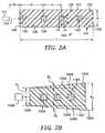
- FIG. 2Ais a cross sectional view of an analytical cell of the invention with microgrooves.
- FIG. 2Bis a cross sectional view of a trapezoidal analytical cell of the invention with microgrooves.
- FIG. 3is a cross sectional view of an analytical cell of the invention with microgrooves, showing the optical path of selected incoming light rays.
- FIG. 4is a cross sectional view of a two part analytical cell of the invention with microgrooves.
- FIG. 5is a cutaway, perspective view of an analytical cell of the invention with capillaries.
- FIG. 6is a cross sectional view of an analytical cell of the invention with capillaries.
- FIG. 7is a cross sectional view of an analytical cell of the invention with capillaries, showing the optical path of selected incoming light rays.
- FIG. 8is a cross sectional view of a two part analytical cell of the invention with capillaries.
- FIG. 9is a cross sectional view of an analytical cell of the invention with close-packed capillaries.
- FIG. 10is a cross sectional view of an analytical cell of the invention with close-packed, staggered capillaries.
- FIG. 11is a cross sectional view of an analytical cell of the invention with capillaries having a non-circular cross sectional shape.
- FIG. 12is a perspective view of a analytical cell of the invention having microgrooves with a square cross sectional shape and adapted to receive capillaries having a circular cross sectional shape.
- FIG. 13A and FIG. 13Bare schematic representations of the incoming light beam in an analytical device of the invention.
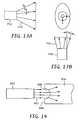
- FIG. 14is a cross sectional view of an analytical cell of the invention with a lens-like face.
- FIG. 15is a cross sectional view of an analytical cell of the invention with a grating-like face.
- FIG. 16is a cross sectional view of an analytical cell of the invention using two sources of illumination.
- FIG. 17is a plot of relative illumination versus microgrooves number for the array of Example 1.
- FIG. 18is a plot of relative illumination versus capillary number for the array of Example 2.
- FIG. 19is a plot of relative illumination versus capillary number for the array of Example 2 with non-optimal optical alignment of the light source and capillaries.
- FIG. 20is a plot of relative illumination versus capillary number for the array of Example 2 with variation in the angular spread of the incoming beam.
- FIG. 21is a plot comparing relative illumination versus capillary number for the array of Example 2 with that of a similar array having capillaries with a square cross sectional shape.
- FIG. 22is a plot of relative illumination versus capillary number for the array of Example 2 with a reflective third interior surface, compared to an otherwise identical array with a non-reflective interior surface, as well as an identical array using dual source illumination.
- FIG. 1Aillustrates the major features of an embodiment of an analytical device of the invention.
- an analytical device 10 of the inventionincludes three principal components: a light source 12 , an analytical cell 14 and a detector 16 .
- the cell 14includes a plurality of conduits 18 with substantially parallel longitudinal axes.
- the conduits 18are arranged in a substantially coplanar array, and are filled with a migration medium (not shown in FIG. 1A ).
- a migration mediumnot shown in FIG. 1A .
- components of the samplemigrate along the conduits and separate into a series of fluorescently labeled analytes.
- a selected analyteenters the fluorescence detection cell 14 , a light beam emitted from the light source 12 illuminates the cell 14 .
- the beam from the light source 12has an optical axis generally in the plane of the conduits 18 and normal to their longitudinal axes.
- the light from the source 12enters the cell 14 , the light is totally internally reflected within the cell 14 to illuminate each of the conduits 18 .
- the cell 14acts as a lightguide that retains a substantial portion of the entering light and efficiently delivers it to each of the conduits in the array. Fluorescent emissions from the analyte are detected by the detector 16 to provide analytical information regarding the composition of the sample.
- the detector 16may include one or more of the following elements: lenses and optical elements for collecting light from the cell 14 , an aperture for exerting precise control over the spatial origin of light, diffraction gratings or prisms for spectral decomposition of the emitted light, and a two-dimensional photodetector such as a charge-coupled device (CCD) camera.
- lenses and optical elementsfor collecting light from the cell 14
- an aperturefor exerting precise control over the spatial origin of light
- diffraction gratings or prismsfor spectral decomposition of the emitted light
- a two-dimensional photodetectorsuch as a charge-coupled device (CCD) camera.
- CCDcharge-coupled device
- the refractive index of the cell 14may be selected with respect to the surrounding medium to confine the incoming light rays 13 from the source 12 to a specific volume.
- the optical intensity (power/unit volume) in this volumeis sufficient to illuminate a selected portion of the each conduit 18 in the array and cause the analytes in that selected portion of each conduit to fluoresce.
- the fluorescent emissions 17 from the analytesthen exit the illuminated volume and are detected by the detector 16 (not shown in FIG. 1B ).
- the shape and dimensions of the illuminated volumemay be controlled to contain the incoming light to provide an analytical device with a desired array size, throughput and resolution.
- the cell 114has a block-like shape with a substantially rectangular cross section having a length, l, measured in FIG. 2A along the z direction, which is substantially greater than its depth, d, measured along the x direction.
- the cell 114includes three conduits 118 having a substantially square cross sectional shape with equal height h and width w.
- the longitudinal axes of the conduits 118are substantially parallel to one another at a substantially equal pitch, p, and the conduits are arranged in a substantially coplanar array.
- Each conduit 118is filled with a migration medium 120 , which is typically a polymeric gel such as, for example, polyacrylamide.
- the cell 114includes a first wall 122 with a first internal surface 124 , as well as a substantially parallel and opposed second wall 126 with a second internal surface 128 facing the first internal surface 124 .
- the cell 114further includes a third wall 130 that is generally normal to the planes of the first and second walls 122 , 126 .
- the third wall 130has an internal surface 132 . Any of the internal surfaces 124 , 128 and 132 may be mirrored or at least partially reflective to reflect light back into the cell 114 . Preferably, at least part of the surface 132 is a mirror.
- a light source 112typically a laser, emits a light beam 113 having an optical axis along the z direction and generally in the plane of the conduits 118 .
- the light source 112is a distance s z from the cell 114 , and the light beam 113 enters the cell 114 at a fourth face 134 and travels along the z direction a defined distance, referred to herein as the atrium, a, until it reaches the first conduit in the array.
- Light rays entering the cell 114are internally reflected and remain confined to the cell 114 to allow substantially uniform illumination of all the conduits 118 in the array.
- Internal reflection in the cell 114is achieved by, for example, selection of materials with appropriate refractive indices at the beam wavelength for the cell 114 , the migration medium 120 and the surrounding medium 140 that is adjacent to at least one wall of the cell 114 .
- the refractive indices of the cell 114 and the migration medium 120should match, or at least be as similar as possible. This reduces the diffusive effect of the surfaces encountered by the incoming light rays.
- the cell 114is preferably made of a material that is transparent or translucent at the wavelength of the light emitted by the light source 112 and has low background fluorescence at the wavelength(s) of the sample fluorophor(s).
- the cell 114is typically a block of glass or plastic, although one skilled in the art could select a wide variety of materials, depending on the wavelength emitted by the source 112 , the refractive indices of the migration medium 120 and the surrounding medium 140 , and the fluorescence properties of the material.
- Suitable materials for the cell 114include, for example, fused silica glass, borosilicate glass, polycarbonate, polymethylmethacrylate, polymethylpentene, and cycloolefin copolymers.
- the substantial internal reflection in the cell 114is also achieved by selecting the shape and dimensions (length (l) and depth (d)) of the cell.
- the length and depth of the cell 114 illustrated in FIG. 2Aare selected to provide a block-like shape, but many other shapes and length and/or depth variations may be used for the cell 114 depending on the intended application.
- the overall level of illumination of the arraytypically decreases as the depth d of the cell increases.
- the illumination of the conduits nearest the light sourcewill be significantly greater than the illumination of the conduits farthest from the light source, i.e. the illumination profile of the array will be more non-uniform.
- illuminationvaries about 25% across a 104 capillary array. If the thickness of the cell is increased to 300 ⁇ m, the variation in illumination is reduced to about 6%, but at a loss of intensity of about 25%. Therefore, in addition to the materials considerations discussed above, the overall dimensions of the cell may be selected to provide a predetermined illumination level and illumination profile required for a particular assay or a particular detector sensitivity level.
- FIG. 2Bshows a cell 114 A with a generally trapezoidal cross sectional shape.
- the cell 114 Aincludes three conduits 118 A having a substantially square cross sectional shape with an equal height h and width w.
- the longitudinal axes of the conduits 118 Aare substantially parallel to one another at a substantially equal pitch, and the conduits are arranged in a substantially coplanar array.
- Each conduit 118 Ais filled with a migration medium 120 A.
- the cell 114 Aincludes a first wall 122 A with a first internal surface 124 A, as well as an opposed second wall 126 A with a second internal surface 128 A facing the first internal surface 124 A.
- the first wall 122 A and the second wall 126 Agradually diverge at angles ⁇ 1 and ⁇ 2 , respectively.
- the cell 114 Afurther includes a third wall 130 A that preferably has a reflective internal surface 132 A.
- a light source 112 Aemits a light beam 113 A having an optical axis along the z direction and generally in the plane of the conduits 118 A and substantially normal to the longitudinal axes thereof.
- the light beam 113 Aenters the cell 114 A at a fourth face 134 A.
- the face 134 Ahas a depth d 1 that is less than the depth d 2 of the opposed face 130 A.
- This trapezoidal cross-sectional shapetends to recapture light that normally would be refracted out of the cell 114 A, which tends to provide more uniform illumination of the conduits farthest from the light source 112 A.
- the trapezoidal shapeprovides more options when, for example, the refractive index of the cell 114 A or the refractive index of the surrounding medium are limited to particular materials, or when there is a large refractive index mismatch between the cell 114 A and the migration medium 118 A.
- the refractive index difference at the interface between the cell and the surrounding mediumconfines the light from the light source to the body of the cell.
- the surrounding mediumis preferably air.
- the refractive index of the surrounding mediummay also be selected to provide a particular level of illumination or illumination profile, and may have an impact on the materials selected for the cell, as well as its dimensions.
- the cell 114may be placed in a liquid or solid medium with a selected index of refraction, which may provide more flexibility in the selection of materials for the cell and the migration medium for a particular assay application or to adapt to a particular detector's dynamic range.
- representative light rays 113 A and 113 Bare emitted by the decollimated source 112 and enter the cell 114 through the fourth face of the cell 134 .
- the ray 113 Bis initially reflected at the first internal surface 128 , illuminates the third conduit 118 C in the array, and is reflected back into the cell at the reflective third internal surface 132 .
- the ray 113 Bis again reflected at the second internal surface 124 , illuminates the first conduit 118 A in the array, and exits the cell 114 at the fourth face 134 .
- the internal reflection of the surrounding cell 114allows very efficient use of the light energy entering the cell to more uniformly illuminate all conduits in the array.
- the cell 150includes a microstructured substrate 152 and a substantially flat cover 154 .
- the cover 154may be made of the same material as the substrate 152 , or may be made of a different material.
- the substrate 152has machined or embossed therein an array of microgrooves 156 .
- the longitudinal axes of the microgrooves 156are substantially parallel, and the microgrooves are substantially uniform and coplanar in the array.
- the microgrooves 156are filled with a migration medium 158 .
- both the substrate and the covermay be microstructured to form a wide variety of cross sectional shapes for the microgrooves 156 .
- an array of capillariesmay be inserted into a lightguide structure to create an analytical cell that substantially enhances the uniformity of illumination of the individual capillaries in the array.
- a coating 211is removed from a series of capillaries 218 filled with a migration medium 220 .
- the stripped, bare ends of the capillaries 218are inserted into appropriately formed passages 215 in a block-like lightguide cell 214 to form a substantially coplanar array.
- the longitudinal axes of the capillaries 218are substantially parallel.
- a light beam 213 emitted from a source 212enters the cell 214 to uniformly illuminate the capillaries 218 and stimulating fluorescence from the fluorescently labeled analytes passing through the cell. This fluorescence is detected by a detector (not shown) to obtain analytical data regarding the analytes in the capillaries 218 .
- the cell 214has a block-like shape with a substantially rectangular cross section having a length, l, measured in FIG. 6 along the z direction, which is substantially greater than its depth, d, measured along the x direction.
- the cell 214includes three capillaries 218 having a substantially circular cross sectional shape with a selected inside diameter (ID) and outside diameter (OD).
- IDinside diameter
- ODoutside diameter
- the longitudinal axes of the capillaries 218are substantially parallel to one another at a substantially equal pitch, p, and the capillaries are arranged in a substantially coplanar array.
- Each capillary 218is filled with a migration medium 220 , which is typically a polymeric gel.
- the cell 214includes a first wall 222 with a first internal surface 224 , as well as a substantially parallel and opposed second wall 226 with a second internal surface 228 facing the first internal surface 224 .
- the cell 214further includes a third wall 230 that is generally normal to the planes of the first and second walls 222 , 226 .
- the third wall 230has an internal surface 232 .
- Any of the internal surfaces 224 , 228 and 232may be mirrored or at least partially reflective to reflect light back into the cell 214 .
- at least part of the surface 232is a mirror (See also FIG. 5 ).
- a light source 212typically a laser, emits a light beam 213 having an optical axis along the z direction and generally in the plane of the capillaries 218 .
- the light source 212is a distance s z from the cell 214 , and the light beam 213 enters the cell 214 at a fourth face 234 and travels along the z direction a defined distance, the atrium, a, until it reaches the first capillary in the array.
- Light rays entering the cell 214are internally reflected and remain confined to the cell to allow substantially uniform illumination of all the capillaries in the array.
- Substantial internal reflection in the cell 214results from selection of materials with appropriate refractive indices at the beam wavelength for the cell 214 , the capillaries, the migration medium 220 , and the surrounding medium 240 .
- the refractive indices of the cell 214 , the capillaries 218 , and the migration medium 220should match, or at least be as similar as possible, to reduce the diffusive effect of the surfaces encountered by the incoming light rays.
- the cell 214is typically a block of glass or plastic, although one skilled in the art could select a wide variety of materials, depending on the wavelength emitted by the source 212 , the refractive indices of the capillaries 218 , the migration medium 220 , the surrounding medium 240 , and the fluorescence properties of the cell material. Suitable materials include fused silica glass and borosilicate glass.
- a representative light rays 213 A and 213 Bare emitted by the decollimated source 212 and enter the cell 214 through the fourth face of the cell 234 .
- the ray 213 Ais initially reflected at the first internal surface 224 , illuminates the second capillary 218 B in the array, and is reflected back into the cell at the reflective second internal surface 228 and the reflective third internal surface 232 .
- the ray 213 Ais again reflected at the first internal surface 124 , illuminates the second capillary 218 B in the array, is reflected at the second internal surface 228 , and exits the cell through the wall 234 .
- the internal reflection of the surrounding cell 214allows very efficient use of the light energy entering the cell to more uniformly illuminate all capillaries in the array. In contrast to conventional devices, the flexibility provided by internal reflection also allows a wide range of capillary inside and outside diameters. As a general rule, the design considerations discussed above with respect to cells with conduits also apply to cells using capillaries to retain the migration medium. However, the walls of the capillaries typically serve as an integral part of the lightguiding portion of the cell, particularly if their refractive indices are well matched with the refractive indices of the cell and the migration medium.
- the cell 250includes a microstructured substrate 252 and a corresponding microstructured cover 254 .
- the substrate 252 and the cover 254have formed therein an array of microgrooves 256 .
- the longitudinal axes of the microgrooves 256are substantially parallel, have arcuate cross sections, and are substantially uniform and coplanar in the array.
- capillaries 257In the microgrooves 256 are placed capillaries 257 , each filled with a migration medium 258 .
- the coverWhen the cover is moved in the direction of arrow A and placed on the substrate 252 , the cell 250 becomes a lightguide.
- Light 262 from a source 260 that enters the substrate 252is substantially internally reflected at the interior surfaces of the substrate 252 and the cover 254 to substantially uniformly illuminate the capillaries 257 in the array.
- the lightguiding properties of the cells described aboveallow for considerable variation in array design.
- the internal reflection of the cellprovides sufficient illumination of the capillaries or microgrooves (also referred to generally herein as conduits) in the array, even if individual conduits are displaced by small amounts from their nominal positions.
- the conduitsneed not be placed at an even pitch, even in their nominal positions.
- the lightguiding properties of the cellmake the arrays of the invention robust against inaccuracies in conduit placement during cell manufacture.
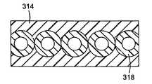
- a cell 314 with a close packed coplanar arrangement of conduits 318appears to provide the highest and most uniform illumination.
- the lightguiding properties of the cells described aboveprovide uniform conduit illumination even for non-planar, close-packed arrangements.
- the cell 414 illustrated in FIG. 10includes capillaries 418 in a staggered, close-packed arrangement. This allows more conduits to be placed into a given fixed field of view of a detector such as a CCD camera, which maximizes the number of samples that can be analyzed simultaneously with one instrument.
- the lightguiding properties of the cells described abovealso accommodate a wide variety of conduit cross sectional shapes. Many different conduit cross sectional shapes are possible, such as circles, squares, rectangles, triangles, ellipses, and the like. However, conduits with square cross sections, including microgrooves and capillaries, are preferred.
- the square cross sectional shapeappears to provide the most uniform illumination of the array, at least when the incoming light is directed in the plane of the array and normal to the longitudinal axes of the conduits. While not wishing to be bound by any theory, the square conduit is believed to present a flat face to the incoming light beam, which minimizes reflection and refraction out the cell. For example, referring to FIG.
- FIG. 11a cell 514 is shown having an array of capillaries 518 with square cross sectional shapes.
- FIG. 12shows a cell 614 constructed as a monolithic block with square internal microgrooves 618 .
- the cell 614includes recesses 619 with a circular cross section and a mating shoulder 621 to allow secure attachment of capillaries 623 to the cell 614 .
- This designexploits the advantages of microgrooves arrays in the detection region of the cell 614 , which has fewer surfaces and a square cross sectional shape to minimize refraction, but preserves the glass capillary format for analytical separations.
- the light beam entering the arraybe shaped and decollimated.
- a source 712emits a beam 713 spread in the direction in the plane of the array and generally normal to the longitudinal axes of the conduits (See, for example, the x axis of FIGS. 2-3 .), by an amount referred to herein as an angular value ⁇ x .
- An optimal range of the value ⁇ xdefined as the standard deviation of a Gaussian distribution of the launch angle, provides a homogenized light front that propagates down the cell.
- ⁇ xis too small, refraction at the first conduit encountered by the beam effectively “shadows” a number of the adjacent conduits in the array, which significantly decreases the illumination of the “downstream” conduits. Above an optimal value of ⁇ x , refraction out of the cell becomes dominant, and the overall intensity received by each conduit appears to decrease monotonically as ⁇ x increases. For example, for a cell in air with a depth of 200 ⁇ m and circular capillaries with a diameter of 120 ⁇ m and placed at a pitch of 240 ⁇ m, an optimal value of ⁇ x appears to be a divergence half angle of about 5° to about 50°, preferably about 10° to about 20°.
- NAnumerical aperture
- beam divergence in the y direction, in the plane of the array(See, for example, the y axis of FIGS. 2-3 .), referred to herein as an angular value ⁇ y , is preferably made small to minimize simultaneous excitation of multiple analytes, particularly in the conduits farthest away from the source.
- An optimal value of ⁇ yappears to be a divergence half angle of approximately 1° or less.
- the decollimation of the beammay be accomplished in many different ways.
- an optical trainmay be placed between the source and the cell to provide the proper beam shape and divergence.
- the face 934 of the cell 914may be shaped to be a plano-concave lens 935 with an appropriate radius of curvature to provide proper beam divergence.
- a cell 1014is shown in FIG. 15 that includes a grating-like face 1034 that diverges the light rays 1013 entering the cell.
- a diffusermay be placed in the beam path to generate divergence in the light rays entering the cell. Many other diverging cell face designs would be apparent to those of ordinary skill in the art.
- the cell 1114may be illuminated with a first light source 1112 A and a second light source 1112 B placed on the opposite side of the cell.
- the second light source 1112 Bemits a light beam 1113 B that enters the cell 1114 through the third face 1130 and has an optical axis that is substantially collinear with the optical axis of the beam 1113 A.
- the interior surface 1132 of the third face 1130is not reflective.
- a cellwas modeled with a microgrooves configuration similar to that shown in FIGS. 2-4 , using a polymer gel as the migration medium.
- the cellhad the dimensions and material properties shown in Table 1 below.
- This cell designwas optically modeled using ray tracing simulations well known in the art.
- the results, which are shown in FIG. 17are expressed in units of relative illumination, defined as the fraction of the power each microgrooves would have absorbed had a 50 ⁇ m laser beam directly illuminated the microgrooves without reflection or refraction.
- the microgrooveswere numbered sequentially from 1 to 104, with microgrooves 1 located nearest the light source. The results indicate extremely uniform illumination for all the microgrooves in the 104 member array.
- a cellwas modeled with capillaries in the general configuration shown in FIGS. 5-8 , using a polymer gel as the migration medium.
- the cellhad the dimensions and material properties shown in Table 2 below.
- This cell designwas optically modeled using well known ray trace simulations and the criteria of Example 1. The results are shown in FIG. 18 . Very uniform illumination is achieved despite the plethora of surfaces in the system. Furthermore, this comes at a reasonable cost in intensity. Overall, the 104 capillaries in the array absorb only about 0.34% of the total beam power.
- the sensitivity of the cell performancewas evaluated with regard to two common types of optical misalignment that may occur during manufacture or operation of an analytical device.
- a cell similar to that of Example 2was modeled.
- a baseline relative illumination valuewas established using a laser light source that was properly aligned with the cell.
- Relative illuminationwas also computed for a case where the light source was tilted about 20° away from the plane of the array.
- relative illuminationwas measured for a case where all 104 capillaries were randomly displaced from their nominal locations by ⁇ 25 ⁇ m in either the x or z directions (See axes in FIG. 6 ). The results are shown in FIG. 19 . Despite rather extreme excursions from optimum optical alignment, neither intensity nor uniformity appear to be significantly reduced.
- the relative illumination intensitywas evaluated with respect to variations in the angular spread of the light beam in the x direction (See axes in FIGS. 6 and 13 ), ⁇ x .
- ⁇ xwas varied from 10° to 50°.
- the resultsare shown in FIG. 20 .
- the results plotted in FIG. 20indicate that if ⁇ x is too small, refraction at the first conduit encountered by the beam effectively “shadows” a number of the adjacent conduits in the array, which significantly decreases illumination. Above an optimal value of ⁇ x , the overall intensity received by each conduit appears to decrease monotonically as ⁇ x increases.
- the relative illumination values of capillaries with circular cross sectionsare compared to those with square cross sections.
- the array of Example 2which had 104 capillaries with circular cross sections, was evaluated.
- a second cellwas modeled with 104 capillaries having square cross sections (See FIG. 11 ). Both cells were evaluated using ray trace simulations well known in the art, and the results are shown in FIG. 21 .
- the flat faces of the square capillariesreduce out-of-plane refraction of incoming light, which enhances illumination.
- Example 2the relative illumination of the 104 capillary array of Example 2 was evaluated using ray trace simulations well known in the art.
- This arrayas shown in FIGS. 5-8 , included a reflective third interior surface 232 .
- a third arraysimilar to that shown FIG. 16 , was modeled using two sources and a non-reflective interior surface 1132 , and then evaluated using ray trace simulations well known in the art. The results are shown in FIG. 22 .
- the single source device with a reflective third interior surfaceprovided the best levels of relative illumination, followed by the dual source device.
- the single source device without the reflective third interior surfaceprovided relatively poor illumination to the downstream capillaries in the array.
Landscapes
- Health & Medical Sciences (AREA)
- General Health & Medical Sciences (AREA)
- Life Sciences & Earth Sciences (AREA)
- Chemical & Material Sciences (AREA)
- Analytical Chemistry (AREA)
- Biochemistry (AREA)
- Physics & Mathematics (AREA)
- General Physics & Mathematics (AREA)
- Immunology (AREA)
- Pathology (AREA)
- Nuclear Medicine, Radiotherapy & Molecular Imaging (AREA)
- Optical Measuring Cells (AREA)
- Investigating, Analyzing Materials By Fluorescence Or Luminescence (AREA)
Abstract
Description
| TABLE 1 | |||
| Number of Microgrooves | 104 | ||
| Microgrooves Width w (μm) | 50 | ||
| Microgrooves Height h (μm) | 50 | ||
| Pitch (μm) | 240 | ||
| Cell Depth (μm) | 200 | ||
| Atrium (mm) | 2 | ||
| Beam Radius (μm) | 25 | ||
| Beam Divergence αx(deg, x | 20 | ||
| direction) | |||
| Beam Divergence αy(deg, | 1 | ||
| direction) | |||
| Source Distance (sz) | 20 | ||
| (μm) | |||
| Index of Refraction of Cell | 1.49 | ||
| Index of Refraction of | 1.41 | ||
| Migration Medium | |||
| Index of Refraction of | 1 | ||
| Surrounding Medium | |||
| Intrinsic Absorption | 0.004 | ||
| Coefficient of Cell (1/mm) | |||
| Intrinsic Absorption | 0.004 | ||
| Coefficient of Migration | |||
| Medium (1/mm) | |||
| Intrinsic Absorption | 0 | ||
| Coefficient of Surrounding | |||
| Medium (1/mm) | |||
| TABLE 2 | |||
| Number of Capillaries | 104 | ||
| Capillaries ID (μm) | 50 | ||
| Capillaries OD (μm) | 120 | ||
| Pitch (μm) | 240 | ||
| Cell Depth (μm) | 200 | ||
| Atrium (mm) | 2 | ||
| Beam Radius (μm) | 25 | ||
| Beam Divergence αx(deg, x | 20 | ||
| direction) | |||
| Beam Divergence αy(deg, | 1 | ||
| direction) | |||
| Source Distance sz | 20 | ||
| (μm) | |||
| Index of Refraction of Cell | 1.49 | ||
| Index of Refraction of | 1.41 | ||
| Medium | |||
| Index of Refraction of | 1.46 | ||
| Capillaries | |||
| Index of Refraction of | 1 | ||
| Surrounding Medium | |||
| Intrinsic Absorption | 0.004 | ||
| Coefficient of Cell (1/mm) | |||
| Intrinsic Absorption | 0.004 | ||
| Coefficient of Migration | |||
| Medium (1/mm) | |||
| Intrinsic Absorption | 0.004 | ||
| Coefficient of Capillaries | |||
| (1/mm) | |||
| Intrinsic Absorption | 0 | ||
| Coefficient of Surrounding | |||
| Medium (1/mm) | |||
Claims (13)
Priority Applications (1)
| Application Number | Priority Date | Filing Date | Title |
|---|---|---|---|
| US11/601,326US8268249B2 (en) | 2001-12-19 | 2006-11-16 | Analytical device with lightguide illumination of capillary and microgroove arrays |
Applications Claiming Priority (2)
| Application Number | Priority Date | Filing Date | Title |
|---|---|---|---|
| US10/028,257US7189361B2 (en) | 2001-12-19 | 2001-12-19 | Analytical device with lightguide Illumination of capillary and microgrooves arrays |
| US11/601,326US8268249B2 (en) | 2001-12-19 | 2006-11-16 | Analytical device with lightguide illumination of capillary and microgroove arrays |
Related Parent Applications (1)
| Application Number | Title | Priority Date | Filing Date |
|---|---|---|---|
| US10/028,257ContinuationUS7189361B2 (en) | 2001-12-19 | 2001-12-19 | Analytical device with lightguide Illumination of capillary and microgrooves arrays |
Publications (2)
| Publication Number | Publication Date |
|---|---|
| US20070065344A1 US20070065344A1 (en) | 2007-03-22 |
| US8268249B2true US8268249B2 (en) | 2012-09-18 |
Family
ID=21842417
Family Applications (2)
| Application Number | Title | Priority Date | Filing Date |
|---|---|---|---|
| US10/028,257Expired - LifetimeUS7189361B2 (en) | 2001-12-19 | 2001-12-19 | Analytical device with lightguide Illumination of capillary and microgrooves arrays |
| US11/601,326Expired - LifetimeUS8268249B2 (en) | 2001-12-19 | 2006-11-16 | Analytical device with lightguide illumination of capillary and microgroove arrays |
Family Applications Before (1)
| Application Number | Title | Priority Date | Filing Date |
|---|---|---|---|
| US10/028,257Expired - LifetimeUS7189361B2 (en) | 2001-12-19 | 2001-12-19 | Analytical device with lightguide Illumination of capillary and microgrooves arrays |
Country Status (6)
| Country | Link |
|---|---|
| US (2) | US7189361B2 (en) |
| EP (1) | EP1459052A4 (en) |
| JP (1) | JP2005514591A (en) |
| AU (1) | AU2002363982A1 (en) |
| CA (1) | CA2467748C (en) |
| WO (1) | WO2003054527A1 (en) |
Cited By (1)
| Publication number | Priority date | Publication date | Assignee | Title |
|---|---|---|---|---|
| US20130265054A1 (en)* | 2010-10-22 | 2013-10-10 | T2 Biosystems, Inc. | Conduit-containing devices and methods for analyte processing and detection |
Families Citing this family (41)
| Publication number | Priority date | Publication date | Assignee | Title |
|---|---|---|---|---|
| US7189361B2 (en)* | 2001-12-19 | 2007-03-13 | 3M Innovative Properties Company | Analytical device with lightguide Illumination of capillary and microgrooves arrays |
| JP2003287502A (en)* | 2002-03-28 | 2003-10-10 | Fuji Photo Film Co Ltd | Humor examination device |
| US7029631B2 (en)* | 2002-04-19 | 2006-04-18 | Agilent Technologies, Inc. | Apparatus for improved light collection |
| US20050214737A1 (en)* | 2004-03-26 | 2005-09-29 | Dejneka Matthew J | Transparent filtered capillaries |
| US7805081B2 (en)* | 2005-08-11 | 2010-09-28 | Pacific Biosciences Of California, Inc. | Methods and systems for monitoring multiple optical signals from a single source |
| US7248361B2 (en)* | 2005-12-22 | 2007-07-24 | Palo Alto Research Center Incorporated | Fluorescence reader based on anti-resonant waveguide excitation |
| US7715001B2 (en) | 2006-02-13 | 2010-05-11 | Pacific Biosciences Of California, Inc. | Methods and systems for simultaneous real-time monitoring of optical signals from multiple sources |
| US7995202B2 (en) | 2006-02-13 | 2011-08-09 | Pacific Biosciences Of California, Inc. | Methods and systems for simultaneous real-time monitoring of optical signals from multiple sources |
| US7692783B2 (en)* | 2006-02-13 | 2010-04-06 | Pacific Biosciences Of California | Methods and systems for simultaneous real-time monitoring of optical signals from multiple sources |
| US7820983B2 (en)* | 2006-09-01 | 2010-10-26 | Pacific Biosciences Of California, Inc. | Substrates, systems and methods for analyzing materials |
| US8207509B2 (en) | 2006-09-01 | 2012-06-26 | Pacific Biosciences Of California, Inc. | Substrates, systems and methods for analyzing materials |
| US20080080059A1 (en)* | 2006-09-28 | 2008-04-03 | Pacific Biosciences Of California, Inc. | Modular optical components and systems incorporating same |
| US20100167413A1 (en)* | 2007-05-10 | 2010-07-01 | Paul Lundquist | Methods and systems for analyzing fluorescent materials with reduced autofluorescence |
| US20080277595A1 (en)* | 2007-05-10 | 2008-11-13 | Pacific Biosciences Of California, Inc. | Highly multiplexed confocal detection systems and methods of using same |
| EP4325209A3 (en) | 2008-09-16 | 2024-05-01 | Pacific Biosciences Of California, Inc. | Integrated optical device |
| US9212995B2 (en) | 2009-03-02 | 2015-12-15 | Mbio Diagnostics, Inc. | System and method for detecting multiple molecules in one assay |
| US8300993B2 (en)* | 2009-03-02 | 2012-10-30 | Mbio Diagnostics, Inc. | Waveguide with integrated lens |
| US8331751B2 (en)* | 2009-03-02 | 2012-12-11 | mBio Diagnositcs, Inc. | Planar optical waveguide with core of low-index-of-refraction interrogation medium |
| US8586347B2 (en) | 2010-09-15 | 2013-11-19 | Mbio Diagnostics, Inc. | System and method for detecting multiple molecules in one assay |
| US9658222B2 (en) | 2009-03-02 | 2017-05-23 | Mbio Diagnostics, Inc. | Planar waveguide based cartridges and associated methods for detecting target analyte |
| US8994946B2 (en) | 2010-02-19 | 2015-03-31 | Pacific Biosciences Of California, Inc. | Integrated analytical system and method |
| EP2933629B1 (en) | 2010-02-19 | 2019-04-10 | Pacific Biosciences Of California, Inc. | System for measuring analytical reactions comprising a socket for an optode array chip |
| US20130330814A1 (en)* | 2012-06-06 | 2013-12-12 | National Taiwan University | Sensor for detection of a target of interest |
| US9372308B1 (en) | 2012-06-17 | 2016-06-21 | Pacific Biosciences Of California, Inc. | Arrays of integrated analytical devices and methods for production |
| EP3734255B1 (en) | 2012-12-18 | 2022-10-19 | Pacific Biosciences Of California, Inc. | An optical analytical device |
| US9624540B2 (en) | 2013-02-22 | 2017-04-18 | Pacific Biosciences Of California, Inc. | Integrated illumination of optical analytical devices |
| WO2015003037A1 (en)* | 2013-07-03 | 2015-01-08 | Wyatt Technology Corporation | Method and apparatus to control sample carryover in analytical instruments |
| JP6111941B2 (en)* | 2013-09-06 | 2017-04-12 | 日本軽金属株式会社 | Biochip substrate |
| JP6324998B2 (en)* | 2013-12-25 | 2018-05-16 | 株式会社日立製作所 | Microchip, method for manufacturing the same, and multichannel fluorescence detection apparatus |
| CN115389599A (en)* | 2014-03-07 | 2022-11-25 | 生命技术公司 | Optical Systems for Capillary Electrophoresis |
| WO2015134943A1 (en) | 2014-03-07 | 2015-09-11 | Life Technologies Corporation | Capillary array cartridge for capillary electrophoresis systems |
| WO2016009467A1 (en)* | 2014-07-14 | 2016-01-21 | 株式会社日立ハイテクノロジーズ | Multichannel analysis device |
| US9606068B2 (en) | 2014-08-27 | 2017-03-28 | Pacific Biosciences Of California, Inc. | Arrays of integrated analytical devices |
| WO2016149397A1 (en) | 2015-03-16 | 2016-09-22 | Pacific Biosciences Of California, Inc. | Integrated devices and systems for free-space optical coupling |
| CN114691585B (en) | 2015-05-07 | 2023-10-13 | 加利福尼亚太平洋生物科学股份有限公司 | Multiprocessor pipeline architecture |
| US10365434B2 (en) | 2015-06-12 | 2019-07-30 | Pacific Biosciences Of California, Inc. | Integrated target waveguide devices and systems for optical coupling |
| JP6731901B2 (en) | 2017-09-29 | 2020-07-29 | 株式会社日立ハイテク | Analysis equipment |
| JP6533603B2 (en)* | 2018-02-28 | 2019-06-19 | 株式会社日立製作所 | Laser beam irradiation method |
| JP2022017606A (en)* | 2018-10-25 | 2022-01-26 | 株式会社 堀場アドバンスドテクノ | Concentration sensor |
| US20220053756A1 (en)* | 2019-01-08 | 2022-02-24 | Changzhou Maternal And Child Health Care Hospital | Chip carrier for single sperm or extremely small amount of sperms |
| KR102624827B1 (en)* | 2021-10-08 | 2024-01-15 | 한국과학기술연구원 | High resolution fluorescence imaging device and method for manufacturing the same |
Citations (34)
| Publication number | Priority date | Publication date | Assignee | Title |
|---|---|---|---|---|
| US2467748A (en) | 1946-01-08 | 1949-04-19 | Jeffrey Company | Vibratory motor |
| US3963310A (en) | 1973-08-20 | 1976-06-15 | The United States Of America As Represented By The Secretary Of The Navy | Liquid crystal waveguide |
| US4310762A (en) | 1980-01-28 | 1982-01-12 | University Of Utah | Calorimetric trace analysis by laser induced thermal lens method |
| US4818710A (en)* | 1984-12-10 | 1989-04-04 | Prutec Limited | Method for optically ascertaining parameters of species in a liquid analyte |
| US5061029A (en) | 1989-10-19 | 1991-10-29 | Brother Kogyo Kabushiki Kaisha | Optical waveguide array, printer, and method of manufacturing the same |
| US5156972A (en)* | 1989-09-05 | 1992-10-20 | The State Of Israel, Atomic Energy Commission, Soreq Nuclear Research Center | Analyte specific chemical sensor with a ligand and an analogue bound on the sensing surface |
| JPH0579469A (en) | 1991-09-17 | 1993-03-30 | Toyota Motor Corp | Variable capacity type vane pump |
| US5252294A (en) | 1988-06-01 | 1993-10-12 | Messerschmitt-Bolkow-Blohm Gmbh | Micromechanical structure |
| US5268080A (en) | 1991-02-28 | 1993-12-07 | Hitachi, Ltd. | DNA detector and DNA detection method |
| US5274240A (en) | 1990-01-12 | 1993-12-28 | The Regents Of The University Of California | Capillary array confocal fluorescence scanner and method |
| US5277780A (en) | 1991-09-13 | 1994-01-11 | Hitachi, Ltd. | Electrophoresis gel migration apparatus |
| US5324401A (en) | 1993-02-05 | 1994-06-28 | Iowa State University Research Foundation, Inc. | Multiplexed fluorescence detector system for capillary electrophoresis |
| US5340715A (en)* | 1991-06-07 | 1994-08-23 | Ciba Corning Diagnostics Corp. | Multiple surface evanescent wave sensor with a reference |
| US5413686A (en) | 1992-07-17 | 1995-05-09 | Beckman Instruments, Inc. | Multi-channel automated capillary electrophoresis analyzer |
| US5414508A (en) | 1992-03-02 | 1995-05-09 | Hitachi, Ltd. | Optical cell and optical detection systems light absorption |
| US5439578A (en) | 1993-06-03 | 1995-08-08 | The Governors Of The University Of Alberta | Multiple capillary biochemical analyzer |
| US5516409A (en) | 1991-02-28 | 1996-05-14 | Hitachi, Ltd. | DNA detector and DNA detection method |
| US5529679A (en) | 1992-02-28 | 1996-06-25 | Hitachi, Ltd. | DNA detector and DNA detection method |
| US5582705A (en) | 1995-05-19 | 1996-12-10 | Iowa State University Research Foundation, Inc. | Multiplexed capillary electrophoresis system |
| JPH0996623A (en) | 1995-09-29 | 1997-04-08 | Hitachi Ltd | Capillary array electrophoresis device |
| US5677196A (en) | 1993-05-18 | 1997-10-14 | University Of Utah Research Foundation | Apparatus and methods for multi-analyte homogeneous fluoro-immunoassays |
| JPH09288088A (en) | 1996-04-23 | 1997-11-04 | Hitachi Ltd | Capillary array electrophoresis device |
| WO1998010122A1 (en) | 1996-09-03 | 1998-03-12 | Northeastern University | Microfabricated hybrid capillary array and multichannel detection assembly |
| JPH10170480A (en) | 1998-01-29 | 1998-06-26 | Hitachi Ltd | Electrophoresis device |
| US5790727A (en) | 1997-02-05 | 1998-08-04 | Brookhaven Science Associates Llc | Laser illumination of multiple capillaries that form a waveguide |
| US5833827A (en) | 1995-09-29 | 1998-11-10 | Hitachi, Ltd. | Capillary array electrophoresis system |
| JPH1175812A (en) | 1997-08-29 | 1999-03-23 | Olympus Optical Co Ltd | Dna capillary |
| WO2000004371A1 (en) | 1998-07-16 | 2000-01-27 | Hanning Instruments Ab | Device for detection of fluorescent species |
| US6064784A (en) | 1997-06-10 | 2000-05-16 | The University Of British Columbia | Electrophoretic, dual refraction frustration of total internal reflection in high efficiency variable reflectivity image displays |
| US6464852B1 (en) | 1998-12-03 | 2002-10-15 | State University Of New York At Stony Brook | Multicapillary bundle for electrophoresis and detection for DNA |
| US6542691B2 (en) | 2000-10-27 | 2003-04-01 | Nippon Sheet Glass Co., Ltd. | Glass capillary array for fluorescence analysis and manufacturing method thereof |
| US6611634B2 (en) | 1996-03-19 | 2003-08-26 | University Of Utah Research Foundation | Lens and associatable flow cell |
| US6613212B1 (en) | 1998-01-30 | 2003-09-02 | Centre National De La Recherche Scientifique | Multiple capillary electrophoresis systems |
| US7189361B2 (en) | 2001-12-19 | 2007-03-13 | 3M Innovative Properties Company | Analytical device with lightguide Illumination of capillary and microgrooves arrays |
Family Cites Families (5)
| Publication number | Priority date | Publication date | Assignee | Title |
|---|---|---|---|---|
| US5054932A (en)* | 1990-12-17 | 1991-10-08 | Kangas Waino J | Segmented barrel extruder device |
| JPH0720591Y2 (en)* | 1992-03-30 | 1995-05-15 | 株式会社島津製作所 | Electrophoresis device |
| JPH07179968A (en)* | 1993-12-22 | 1995-07-18 | Daido Metal Co Ltd | Aluminum alloy for sliding material |
| US5528705A (en)* | 1994-08-26 | 1996-06-18 | Unisys Corporation | JPEG synchronization tag |
| US5695636A (en)* | 1996-01-31 | 1997-12-09 | Caterpillar Inc. | Fluid filter having a reusable filter housing and a replaceable filter element |
- 2001
- 2001-12-19USUS10/028,257patent/US7189361B2/ennot_activeExpired - Lifetime
- 2002
- 2002-12-09JPJP2003555191Apatent/JP2005514591A/enactivePending
- 2002-12-09AUAU2002363982Apatent/AU2002363982A1/ennot_activeAbandoned
- 2002-12-09EPEP02798500Apatent/EP1459052A4/ennot_activeWithdrawn
- 2002-12-09CACA2467748Apatent/CA2467748C/ennot_activeExpired - Fee Related
- 2002-12-09WOPCT/US2002/039472patent/WO2003054527A1/enactiveApplication Filing
- 2006
- 2006-11-16USUS11/601,326patent/US8268249B2/ennot_activeExpired - Lifetime
Patent Citations (44)
| Publication number | Priority date | Publication date | Assignee | Title |
|---|---|---|---|---|
| US2467748A (en) | 1946-01-08 | 1949-04-19 | Jeffrey Company | Vibratory motor |
| US3963310A (en) | 1973-08-20 | 1976-06-15 | The United States Of America As Represented By The Secretary Of The Navy | Liquid crystal waveguide |
| US4310762A (en) | 1980-01-28 | 1982-01-12 | University Of Utah | Calorimetric trace analysis by laser induced thermal lens method |
| US4818710A (en)* | 1984-12-10 | 1989-04-04 | Prutec Limited | Method for optically ascertaining parameters of species in a liquid analyte |
| US5252294A (en) | 1988-06-01 | 1993-10-12 | Messerschmitt-Bolkow-Blohm Gmbh | Micromechanical structure |
| US5156972A (en)* | 1989-09-05 | 1992-10-20 | The State Of Israel, Atomic Energy Commission, Soreq Nuclear Research Center | Analyte specific chemical sensor with a ligand and an analogue bound on the sensing surface |
| US5061029A (en) | 1989-10-19 | 1991-10-29 | Brother Kogyo Kabushiki Kaisha | Optical waveguide array, printer, and method of manufacturing the same |
| US5274240A (en) | 1990-01-12 | 1993-12-28 | The Regents Of The University Of California | Capillary array confocal fluorescence scanner and method |
| US5667656A (en) | 1991-02-28 | 1997-09-16 | Hitachi, Ltd. | DNA detector and DNA detection method |
| US5516409A (en) | 1991-02-28 | 1996-05-14 | Hitachi, Ltd. | DNA detector and DNA detection method |
| US5268080A (en) | 1991-02-28 | 1993-12-07 | Hitachi, Ltd. | DNA detector and DNA detection method |
| US5314602A (en) | 1991-02-28 | 1994-05-24 | Hitachi, Ltd. | DNA detector and DNA detection method |
| US5759374A (en) | 1991-02-28 | 1998-06-02 | Hitachi, Ltd. | DNA detector and DNA detection method |
| US5954932A (en) | 1991-02-28 | 1999-09-21 | Hitachi, Ltd. | DNA detector and DNA detection method |
| US5964998A (en) | 1991-02-28 | 1999-10-12 | Hitachi, Ltd. | DNA detector and DNA detection method |
| US5340715A (en)* | 1991-06-07 | 1994-08-23 | Ciba Corning Diagnostics Corp. | Multiple surface evanescent wave sensor with a reference |
| US5277780A (en) | 1991-09-13 | 1994-01-11 | Hitachi, Ltd. | Electrophoresis gel migration apparatus |
| JPH0579469A (en) | 1991-09-17 | 1993-03-30 | Toyota Motor Corp | Variable capacity type vane pump |
| US5529679A (en) | 1992-02-28 | 1996-06-25 | Hitachi, Ltd. | DNA detector and DNA detection method |
| US5414508A (en) | 1992-03-02 | 1995-05-09 | Hitachi, Ltd. | Optical cell and optical detection systems light absorption |
| US5413686A (en) | 1992-07-17 | 1995-05-09 | Beckman Instruments, Inc. | Multi-channel automated capillary electrophoresis analyzer |
| US5498324A (en) | 1993-02-05 | 1996-03-12 | Iowa State University Research Foundation, Inc. | Multiplexed fluorescence detector system for capillary electrophoresis |
| US5324401A (en) | 1993-02-05 | 1994-06-28 | Iowa State University Research Foundation, Inc. | Multiplexed fluorescence detector system for capillary electrophoresis |
| US5677196A (en) | 1993-05-18 | 1997-10-14 | University Of Utah Research Foundation | Apparatus and methods for multi-analyte homogeneous fluoro-immunoassays |
| US5439578A (en) | 1993-06-03 | 1995-08-08 | The Governors Of The University Of Alberta | Multiple capillary biochemical analyzer |
| US5741412A (en) | 1993-06-03 | 1998-04-21 | University Of Alberta | Multiple capillary biochemical analyzer |
| US5695626A (en) | 1995-05-19 | 1997-12-09 | Iowa State University Research Foundation | Capillaries for use in a multiplexed capillary electrophoresis system |
| US5741411A (en) | 1995-05-19 | 1998-04-21 | Iowa State University Research Foundation | Multiplexed capillary electrophoresis system |
| US5582705A (en) | 1995-05-19 | 1996-12-10 | Iowa State University Research Foundation, Inc. | Multiplexed capillary electrophoresis system |
| JPH0996623A (en) | 1995-09-29 | 1997-04-08 | Hitachi Ltd | Capillary array electrophoresis device |
| US5833827A (en) | 1995-09-29 | 1998-11-10 | Hitachi, Ltd. | Capillary array electrophoresis system |
| US6611634B2 (en) | 1996-03-19 | 2003-08-26 | University Of Utah Research Foundation | Lens and associatable flow cell |
| JPH09288088A (en) | 1996-04-23 | 1997-11-04 | Hitachi Ltd | Capillary array electrophoresis device |
| US5938908A (en) | 1996-04-23 | 1999-08-17 | Hitachi, Ltd. | Capillary array electrophoresis system |
| WO1998010122A1 (en) | 1996-09-03 | 1998-03-12 | Northeastern University | Microfabricated hybrid capillary array and multichannel detection assembly |
| US5790727A (en) | 1997-02-05 | 1998-08-04 | Brookhaven Science Associates Llc | Laser illumination of multiple capillaries that form a waveguide |
| US6064784A (en) | 1997-06-10 | 2000-05-16 | The University Of British Columbia | Electrophoretic, dual refraction frustration of total internal reflection in high efficiency variable reflectivity image displays |
| JPH1175812A (en) | 1997-08-29 | 1999-03-23 | Olympus Optical Co Ltd | Dna capillary |
| JPH10170480A (en) | 1998-01-29 | 1998-06-26 | Hitachi Ltd | Electrophoresis device |
| US6613212B1 (en) | 1998-01-30 | 2003-09-02 | Centre National De La Recherche Scientifique | Multiple capillary electrophoresis systems |
| WO2000004371A1 (en) | 1998-07-16 | 2000-01-27 | Hanning Instruments Ab | Device for detection of fluorescent species |
| US6464852B1 (en) | 1998-12-03 | 2002-10-15 | State University Of New York At Stony Brook | Multicapillary bundle for electrophoresis and detection for DNA |
| US6542691B2 (en) | 2000-10-27 | 2003-04-01 | Nippon Sheet Glass Co., Ltd. | Glass capillary array for fluorescence analysis and manufacturing method thereof |
| US7189361B2 (en) | 2001-12-19 | 2007-03-13 | 3M Innovative Properties Company | Analytical device with lightguide Illumination of capillary and microgrooves arrays |
Non-Patent Citations (12)
Cited By (2)
| Publication number | Priority date | Publication date | Assignee | Title |
|---|---|---|---|---|
| US20130265054A1 (en)* | 2010-10-22 | 2013-10-10 | T2 Biosystems, Inc. | Conduit-containing devices and methods for analyte processing and detection |
| US9568575B2 (en)* | 2010-10-22 | 2017-02-14 | T2 Biosystems, Inc. | Conduit-containing devices and methods for analyte processing and detection |
Also Published As
| Publication number | Publication date |
|---|---|
| EP1459052A4 (en) | 2008-12-10 |
| AU2002363982A1 (en) | 2003-07-09 |
| CA2467748A1 (en) | 2003-07-03 |
| US20070065344A1 (en) | 2007-03-22 |
| US20030113935A1 (en) | 2003-06-19 |
| WO2003054527A1 (en) | 2003-07-03 |
| US7189361B2 (en) | 2007-03-13 |
| JP2005514591A (en) | 2005-05-19 |
| CA2467748C (en) | 2010-11-30 |
| EP1459052A1 (en) | 2004-09-22 |
Similar Documents
| Publication | Publication Date | Title |
|---|---|---|
| US8268249B2 (en) | Analytical device with lightguide illumination of capillary and microgroove arrays | |
| US5790727A (en) | Laser illumination of multiple capillaries that form a waveguide | |
| US6627433B2 (en) | Multi-channel analyte-separation device employing side-entry excitation | |
| US8597485B2 (en) | Optical detection alignment coupling apparatus | |
| US9090666B2 (en) | Lensed optical fiber for illuminating capillary tube | |
| EP0773438B1 (en) | Automated optical alignment using a galvanometric scanner | |
| US6464852B1 (en) | Multicapillary bundle for electrophoresis and detection for DNA | |
| US6797139B2 (en) | Detection cell for guiding excitation light therein and method for using same | |
| JP3450947B2 (en) | Fluorescence detection type capillary array electrophoresis device | |
| US8304712B2 (en) | Light focusing in linear channel arrays | |
| EP1384061B1 (en) | Energy beam guide for an electrophoresis system | |
| US7250099B2 (en) | Optical detection alignment coupling apparatus | |
| US20050211558A1 (en) | Capillary and electrophoresis apparatus | |
| JP3839412B2 (en) | Fluorescence detection type capillary array electrophoresis apparatus | |
| AU2002327802A1 (en) | Multi-capillary array electrophoresis device | |
| WO2003027028A1 (en) | Multi-capillary array electrophoresis device | |
| Tsupryk et al. | Novel design of multicapillary arrays for high‐throughput DNA sequencing | |
| Dhadwal et al. | DNA sequencing by multiple capillaries that form a waveguide | |
| Quesada et al. | DNA sequencing by multiple capillaries that form a waveguide Harbans S. Dhadwal State University of New York at Stony Brook, Department of Electrical Engineering, Stony Brook, New Yo | |
| CZ2001196A3 (en) | Device for detecting one or several fluorescent components and use of such device | |
| JP2006153683A (en) | Electrophoresis device |
Legal Events
| Date | Code | Title | Description |
|---|---|---|---|
| AS | Assignment | Owner name:BANK OF AMERICA, N.A, AS COLLATERAL AGENT, WASHING Free format text:SECURITY AGREEMENT;ASSIGNOR:APPLIED BIOSYSTEMS, LLC;REEL/FRAME:021976/0001 Effective date:20081121 Owner name:BANK OF AMERICA, N.A, AS COLLATERAL AGENT,WASHINGT Free format text:SECURITY AGREEMENT;ASSIGNOR:APPLIED BIOSYSTEMS, LLC;REEL/FRAME:021976/0001 Effective date:20081121 | |
| ZAAB | Notice of allowance mailed | Free format text:ORIGINAL CODE: MN/=. | |
| AS | Assignment | Owner name:APPLIED BIOSYSTEMS, INC., CALIFORNIA Free format text:LIEN RELEASE;ASSIGNOR:BANK OF AMERICA, N.A.;REEL/FRAME:030182/0677 Effective date:20100528 | |
| CC | Certificate of correction | ||
| STCV | Information on status: appeal procedure | Free format text:COURT PROCEEDINGS TERMINATED | |
| FPAY | Fee payment | Year of fee payment:4 | |
| AS | Assignment | Owner name:APPLIED BIOSYSTEMS, LLC, CALIFORNIA Free format text:CORRECTIVE ASSIGNMENT TO CORRECT THE RECEIVING PARTY NAME PREVIOUSLY RECORDED AT REEL: 030182 FRAME: 0710. ASSIGNOR(S) HEREBY CONFIRMS THE RELEASE OF SECURITY INTEREST;ASSIGNOR:BANK OF AMERICA, N.A.;REEL/FRAME:038025/0739 Effective date:20100528 Owner name:APPLIED BIOSYSTEMS, LLC, CALIFORNIA Free format text:CORRECTIVE ASSIGNMENT TO CORRECT THE RECEIVING PARTY NAME PREVIOUSLY RECORDED AT REEL: 030182 FRAME: 0677. ASSIGNOR(S) HEREBY CONFIRMS THE RELEASE OF SECURITY INTEREST;ASSIGNOR:BANK OF AMERICA, N.A.;REEL/FRAME:038025/0739 Effective date:20100528 | |
| MAFP | Maintenance fee payment | Free format text:PAYMENT OF MAINTENANCE FEE, 8TH YEAR, LARGE ENTITY (ORIGINAL EVENT CODE: M1552); ENTITY STATUS OF PATENT OWNER: LARGE ENTITY Year of fee payment:8 | |
| AS | Assignment | Owner name:SOLVENTUM INTELLECTUAL PROPERTIES COMPANY, MINNESOTA Free format text:ASSIGNMENT OF ASSIGNORS INTEREST;ASSIGNOR:3M INNOVATIVE PROPERTIES COMPANY;REEL/FRAME:066333/0199 Effective date:20240201 | |
| FEPP | Fee payment procedure | Free format text:MAINTENANCE FEE REMINDER MAILED (ORIGINAL EVENT CODE: REM.); ENTITY STATUS OF PATENT OWNER: LARGE ENTITY | |
| FEPP | Fee payment procedure | Free format text:PETITION RELATED TO MAINTENANCE FEES FILED (ORIGINAL EVENT CODE: PMFP); ENTITY STATUS OF PATENT OWNER: LARGE ENTITY | |
| FEPP | Fee payment procedure | Free format text:SURCHARGE, PETITION TO ACCEPT PYMT AFTER EXP, UNINTENTIONAL (ORIGINAL EVENT CODE: M1558); ENTITY STATUS OF PATENT OWNER: LARGE ENTITY | |
| MAFP | Maintenance fee payment | Free format text:PAYMENT OF MAINTENANCE FEE, 12TH YEAR, LARGE ENTITY (ORIGINAL EVENT CODE: M1553); ENTITY STATUS OF PATENT OWNER: LARGE ENTITY Year of fee payment:12 | |
| LAPS | Lapse for failure to pay maintenance fees | Free format text:PATENT EXPIRED FOR FAILURE TO PAY MAINTENANCE FEES (ORIGINAL EVENT CODE: EXP.); ENTITY STATUS OF PATENT OWNER: LARGE ENTITY | |
| STCH | Information on status: patent discontinuation | Free format text:PATENT EXPIRED DUE TO NONPAYMENT OF MAINTENANCE FEES UNDER 37 CFR 1.362 | |
| PRDP | Patent reinstated due to the acceptance of a late maintenance fee | Effective date:20241106 | |
| FEPP | Fee payment procedure | Free format text:PETITION RELATED TO MAINTENANCE FEES GRANTED (ORIGINAL EVENT CODE: PMFG); ENTITY STATUS OF PATENT OWNER: LARGE ENTITY | |
| STCF | Information on status: patent grant | Free format text:PATENTED CASE | |
| FP | Lapsed due to failure to pay maintenance fee | Effective date:20240918 |