US8267969B2 - Screw systems and methods for use in stabilization of bone structures - Google Patents
Screw systems and methods for use in stabilization of bone structuresDownload PDFInfo
- Publication number
- US8267969B2 US8267969B2US11/726,093US72609307AUS8267969B2US 8267969 B2US8267969 B2US 8267969B2US 72609307 AUS72609307 AUS 72609307AUS 8267969 B2US8267969 B2US 8267969B2
- Authority
- US
- United States
- Prior art keywords
- seat
- rod
- coupler
- cap
- screw
- Prior art date
- Legal status (The legal status is an assumption and is not a legal conclusion. Google has not performed a legal analysis and makes no representation as to the accuracy of the status listed.)
- Active, expires
Links
- 210000000988bone and boneAnatomy0.000titleclaimsabstractdescription117
- 238000000034methodMethods0.000titleabstractdescription50
- 230000006641stabilisationEffects0.000titleabstractdescription14
- 238000011105stabilizationMethods0.000titleabstractdescription14
- 230000033001locomotionEffects0.000claimsabstractdescription53
- 230000007246mechanismEffects0.000claimsdescription40
- KJLPSBMDOIVXSN-UHFFFAOYSA-N4-[4-[2-[4-(3,4-dicarboxyphenoxy)phenyl]propan-2-yl]phenoxy]phthalic acidChemical compoundC=1C=C(OC=2C=C(C(C(O)=O)=CC=2)C(O)=O)C=CC=1C(C)(C)C(C=C1)=CC=C1OC1=CC=C(C(O)=O)C(C(O)=O)=C1KJLPSBMDOIVXSN-UHFFFAOYSA-N0.000claimsdescription23
- 238000003780insertionMethods0.000claimsdescription18
- 230000037431insertionEffects0.000claimsdescription18
- 230000000717retained effectEffects0.000claimsdescription17
- 230000009471actionEffects0.000claimsdescription6
- 230000006835compressionEffects0.000claimsdescription5
- 238000007906compressionMethods0.000claimsdescription5
- 230000002441reversible effectEffects0.000claimsdescription4
- 230000013011matingEffects0.000claimsdescription3
- 210000002445nippleAnatomy0.000claimsdescription2
- 230000000295complement effectEffects0.000claims6
- 208000002193PainDiseases0.000abstractdescription6
- 238000009434installationMethods0.000abstractdescription5
- 230000002829reductive effectEffects0.000abstractdescription5
- 210000002517zygapophyseal jointAnatomy0.000description14
- 230000008569processEffects0.000description10
- 238000002513implantationMethods0.000description9
- 230000006870functionEffects0.000description7
- 230000004927fusionEffects0.000description7
- 208000037265diseases, disorders, signs and symptomsDiseases0.000description6
- 208000035475disorderDiseases0.000description4
- 230000000694effectsEffects0.000description4
- 210000001519tissueAnatomy0.000description4
- 206010072005Spinal painDiseases0.000description3
- 230000008901benefitEffects0.000description3
- 230000001010compromised effectEffects0.000description3
- 238000005516engineering processMethods0.000description3
- 239000007943implantSubstances0.000description3
- 208000014674injuryDiseases0.000description3
- 239000000463materialSubstances0.000description3
- 230000036961partial effectEffects0.000description3
- 125000006850spacer groupChemical group0.000description3
- 230000008733traumaEffects0.000description3
- 206010017076FractureDiseases0.000description2
- 206010061246Intervertebral disc degenerationDiseases0.000description2
- 206010028980NeoplasmDiseases0.000description2
- 208000002607PseudarthrosisDiseases0.000description2
- 206010058907Spinal deformityDiseases0.000description2
- 208000007103SpondylolisthesisDiseases0.000description2
- 210000003484anatomyAnatomy0.000description2
- 238000005452bendingMethods0.000description2
- 239000004568cementSubstances0.000description2
- 208000018180degenerative disc diseaseDiseases0.000description2
- 201000010099diseaseDiseases0.000description2
- 239000003292glueSubstances0.000description2
- 208000021600intervertebral disc degenerative diseaseDiseases0.000description2
- 210000003041ligamentAnatomy0.000description2
- 230000000670limiting effectEffects0.000description2
- 230000003278mimic effectEffects0.000description2
- 238000011084recoveryMethods0.000description2
- 208000005198spinal stenosisDiseases0.000description2
- 230000007480spreadingEffects0.000description2
- 230000000087stabilizing effectEffects0.000description2
- 239000011800void materialSubstances0.000description2
- 208000012659Joint diseaseDiseases0.000description1
- 208000020307Spinal diseaseDiseases0.000description1
- 238000010521absorption reactionMethods0.000description1
- 230000002411adverseEffects0.000description1
- 238000013459approachMethods0.000description1
- 208000037873arthrodesisDiseases0.000description1
- 230000000712assemblyEffects0.000description1
- 238000000429assemblyMethods0.000description1
- 238000005422blastingMethods0.000description1
- 230000008878couplingEffects0.000description1
- 238000010168coupling processMethods0.000description1
- 238000005859coupling reactionMethods0.000description1
- 230000006378damageEffects0.000description1
- 230000007850degenerationEffects0.000description1
- 230000000994depressogenic effectEffects0.000description1
- 230000006866deteriorationEffects0.000description1
- 239000012530fluidSubstances0.000description1
- 238000002594fluoroscopyMethods0.000description1
- 230000035876healingEffects0.000description1
- 208000015181infectious diseaseDiseases0.000description1
- 238000002347injectionMethods0.000description1
- 239000007924injectionSubstances0.000description1
- 238000002324minimally invasive surgeryMethods0.000description1
- 210000003205muscleAnatomy0.000description1
- 230000037390scarringEffects0.000description1
- 230000035939shockEffects0.000description1
- 239000007787solidSubstances0.000description1
- 230000003746surface roughnessEffects0.000description1
- 230000001225therapeutic effectEffects0.000description1
Images


Classifications
- A—HUMAN NECESSITIES
- A61—MEDICAL OR VETERINARY SCIENCE; HYGIENE
- A61B—DIAGNOSIS; SURGERY; IDENTIFICATION
- A61B17/00—Surgical instruments, devices or methods
- A61B17/56—Surgical instruments or methods for treatment of bones or joints; Devices specially adapted therefor
- A61B17/58—Surgical instruments or methods for treatment of bones or joints; Devices specially adapted therefor for osteosynthesis, e.g. bone plates, screws or setting implements
- A61B17/68—Internal fixation devices, including fasteners and spinal fixators, even if a part thereof projects from the skin
- A61B17/70—Spinal positioners or stabilisers, e.g. stabilisers comprising fluid filler in an implant
- A61B17/7001—Screws or hooks combined with longitudinal elements which do not contact vertebrae
- A61B17/7032—Screws or hooks with U-shaped head or back through which longitudinal rods pass
- A—HUMAN NECESSITIES
- A61—MEDICAL OR VETERINARY SCIENCE; HYGIENE
- A61B—DIAGNOSIS; SURGERY; IDENTIFICATION
- A61B17/00—Surgical instruments, devices or methods
- A61B17/56—Surgical instruments or methods for treatment of bones or joints; Devices specially adapted therefor
- A61B17/58—Surgical instruments or methods for treatment of bones or joints; Devices specially adapted therefor for osteosynthesis, e.g. bone plates, screws or setting implements
- A61B17/68—Internal fixation devices, including fasteners and spinal fixators, even if a part thereof projects from the skin
- A61B17/70—Spinal positioners or stabilisers, e.g. stabilisers comprising fluid filler in an implant
- A61B17/7001—Screws or hooks combined with longitudinal elements which do not contact vertebrae
- A61B17/7002—Longitudinal elements, e.g. rods
- A61B17/7004—Longitudinal elements, e.g. rods with a cross-section which varies along its length
- A61B17/7005—Parts of the longitudinal elements, e.g. their ends, being specially adapted to fit in the screw or hook heads
- A—HUMAN NECESSITIES
- A61—MEDICAL OR VETERINARY SCIENCE; HYGIENE
- A61B—DIAGNOSIS; SURGERY; IDENTIFICATION
- A61B17/00—Surgical instruments, devices or methods
- A61B17/56—Surgical instruments or methods for treatment of bones or joints; Devices specially adapted therefor
- A61B17/58—Surgical instruments or methods for treatment of bones or joints; Devices specially adapted therefor for osteosynthesis, e.g. bone plates, screws or setting implements
- A61B17/68—Internal fixation devices, including fasteners and spinal fixators, even if a part thereof projects from the skin
- A61B17/70—Spinal positioners or stabilisers, e.g. stabilisers comprising fluid filler in an implant
- A61B17/7001—Screws or hooks combined with longitudinal elements which do not contact vertebrae
- A61B17/7035—Screws or hooks, wherein a rod-clamping part and a bone-anchoring part can pivot relative to each other
- A61B17/7037—Screws or hooks, wherein a rod-clamping part and a bone-anchoring part can pivot relative to each other wherein pivoting is blocked when the rod is clamped
- A—HUMAN NECESSITIES
- A61—MEDICAL OR VETERINARY SCIENCE; HYGIENE
- A61B—DIAGNOSIS; SURGERY; IDENTIFICATION
- A61B17/00—Surgical instruments, devices or methods
- A61B17/56—Surgical instruments or methods for treatment of bones or joints; Devices specially adapted therefor
- A61B17/58—Surgical instruments or methods for treatment of bones or joints; Devices specially adapted therefor for osteosynthesis, e.g. bone plates, screws or setting implements
- A61B17/68—Internal fixation devices, including fasteners and spinal fixators, even if a part thereof projects from the skin
- A61B17/70—Spinal positioners or stabilisers, e.g. stabilisers comprising fluid filler in an implant
- A61B17/7001—Screws or hooks combined with longitudinal elements which do not contact vertebrae
- A61B17/7035—Screws or hooks, wherein a rod-clamping part and a bone-anchoring part can pivot relative to each other
- A61B17/704—Screws or hooks, wherein a rod-clamping part and a bone-anchoring part can pivot relative to each other the longitudinal element passing through a ball-joint in the screw head
Definitions
- 11/427,738is also a continuation-in-part of U.S. patent application Ser. No. 11/362,366 filed on Feb. 23, 2006, which is a continuation-in-part of U.S. Patent Application Ser. No. 60/701,660 filed on Jul. 22, 2005, all of which are incorporated herein by reference in their entirety.
- This applicationis also a continuation-in-part of U.S. patent application Ser. No. 11/586,849 entitled “Systems and methods for stabilization of bone structures” filed on Oct. 25, 2006, which is a continuation-in-part of U.S. patent application Ser. No. 11/362,366 filed on Feb. 23, 2006, which is a continuation-in-part of U.S. Patent Application Ser. No. 60/701,660 filed on Jul. 22, 2005, all of which are incorporated herein by reference in their entirety.
- the present inventiongenerally relates to surgical instruments and methods for using these instruments. More particularly, but not exclusively, minimally invasive methods of stabilizing one or more bone structures are disclosed.
- FIGS. 1A-1Billustrate a portion of the human spine having a superior vertebra 2 and an inferior vertebra 4 , with an intervertebral disc 6 located in between the two vertebral bodies.
- the superior vertebra 2has superior facet joints 8 a and 8 b , inferior facet joints 10 a and 10 b , posterior arch 16 and spinous process 18 .
- Pedicles 3 a and 3 binterconnect the respective superior facet joints 8 a , 8 b to the vertebral body 2 . Extending laterally from superior facet joints 8 a , 8 b are transverse processes 7 a and 7 b , respectively.
- inferior vertebra 4Extending between each inferior facet joints 10 a and 10 b and the spinous process 18 are lamina 5 a and 5 b , respectively.
- inferior vertebra 4has superior facet joints 12 a and 12 b , superior pedicles 9 a and 9 b , transverse processes 11 a and 11 b , inferior facet joints 14 a and 14 b , lamina 15 a and 15 b , posterior arch 20 , spinous process 22 .
- Each spinal motion segmentenables motion along three orthogonal axis, both in rotation and in translation.
- the various spinal motionsare illustrated in FIGS. 1C-1D .
- FIG. 1Cillustrates flexion and extension motions, anterior translation, and axial loading
- FIG. 1Dillustrates lateral bending motion and lateral translation motion.
- a normally functioning spinal motion segmentprovides physiological limits and stiffness in each rotational and translational direction to create a stable and strong column structure to support physiological loads.
- Various disorders of the spinecan produce debilitating pain that can affect a spinal-motion segment's ability to properly function.
- the specific location or source of spinal painis most often an affected intervertebral disc or facet joint.
- a disorder in one location or spinal componentcan lead to eventual deterioration or disorder, and ultimately, pain in the other.
- Spine fusionis a procedure in which two or more adjacent vertebral bodies are fused together. While spine fusion generally helps to eliminate certain types of pain, it has been shown to decrease function by limiting the range of motion for patients in flexion, extension, rotation and lateral bending. Furthermore, the fusion creates increased stresses on adjacent non-fused motion segments and accelerated degeneration of the motion segments.
- Dynamic posterior stabilizationMost recently, surgical-based technologies, referred to as “dynamic posterior stabilization,” have been developed to address spinal pain resulting from more than one disorder, when more than one structure of the spine have been compromised. An objective of such technologies is to provide the support of fusion-based implants while maximizing the natural biomechanics of the spine. Dynamic posterior stabilization systems typically fall into one of two general categories: (1) interspinous spacers and (2) posterior pedicle screw-based systems.
- interspinous spacersexamples include U.S. Pat. Nos. Re. 36,211, 5,645,599, 6,695,842, 6,716,245 and 6,761,720.
- pedicle screw-based systemsare disclosed in U.S. Pat. Nos. 5,015,247, 5,484,437, 5,489,308, 5,609,636 and 5,658,337, 5,741,253, 6,080,155, 6,096,038, 6,264,656 and 6,270,498. These types of systems involve the use of screws which are positioned in the vertebral body through the pedicle. Certain types of these pedicle screw-based systems may be used to augment compromised facet joints, while others require removal of the spinous process and/or the facet joints for implantation. One such system, employs a cord which is extended between the pedicle screws and a fairly rigid spacer which is passed over the cord and positioned between the screws.
- a bone screw systemincludes a threaded section and a screw head section integrally connected to the threaded section.
- the systemincludes a coupler having a screw head receiving portion configured to receive at least a portion of the screw head section of the screw.
- the coupleralso includes a rod receiving portion integral with the screw head receiving portion.
- the rod receiving portionis configured to receive a rod.
- the systemincludes a seat having a first end and a second end.
- the seatfurther includes at least one sidewall extending between the first end and the second end, a cap receiving portion configured to receive a cap at the first end and a coupler receiving portion configured to receive the coupler.
- the seatincludes a bottom opening at the second end and a top opening at the first end.
- the systemincludes a cap configured to close the top opening of the seat.
- the caphas a top surface and a bottom surface interconnected by an outer surface and an inner surface.
- the inner surfacedefines a threaded set screw receiving portion and the outer surface defines at least one seat-engagement feature for engagement with the cap receiving portion of the seat.
- the systemincludes a set screw having a top surface and a bottom surface interconnected by a threaded outer surface.
- the set screwis configured to be threadingly engaged with the set screw receiving portion of the cap.
- the systemfurther includes a retainer configured to retain the coupler inside the seat.
- a rodis provided.
- the rodhas a first end and a second end.
- the first end of the rodis configured to connect to the rod receiving portion of the coupler. At least a portion of the screw head section is disposed inside the screw head receiving portion of the coupler.
- the screwis inserted in the bottom opening of the seat and the coupler is retained inside the seat via the retainer pressed between the coupler and the seat.
- the first end of the rodis removably connected to the rod receiving portion of the coupler.
- the capis removably inserted into the cap receiving portion of the seat and retained therein via the at least one seat-engagement feature on the outer surface of the cap.
- the set screwis disposed in the set screw receiving portion of the cap.
- the rodis disposed in the rod channel with the cap disposed in the cap receiving portion of the seat. Upon advancement of the screw, the bottom surface of the set screw contacts at least a portion of the rod within the seat and the bone screw and rod is locked into position with advancement of the set screw into the seat.
- a bone screw systemhaving a locked configuration and an unlocked configuration.
- the bone screw systemincludes a rod and a seat.
- the seathas a first end and a second end and is configured to receive at least a portion of the rod inside the seat such that the rod has a range of motion relative to the seat while in the unlocked configuration.
- a bone screw having a first end and a second endis also provided. At least a portion of the first end of the bone screw is disposed inside the seat.
- the screwhas a range of motion relative to the seat when in the unlocked configuration.
- a lock down mechanismis removably disposed inside the seat at the first end of the seat. At least a portion of the rod is located between the lock down mechanism and the first end of the screw.
- the lock down mechanismis operable between a locked configuration and an unlocked configuration such that both the rod or the screw is locked into position as the lock down mechanism operates from the unlocked configuration to the locked configuration.
- a bone screw systemincludes a rod and a bone screw having a first end and a second end.
- the systemincludes a seat having a bottom opening.
- a couplerhaving a rod receiving portion and a bone screw receiving portion.
- the rod receiving portion of the coupleris configured to connect to the rod and the bone screw receiving portion is configured to house at least a portion of the first end of the bone screw.
- At least a portion of the bone screwis retained in the bone screw receiving portion of the coupler which is retained inside the seat such that the bone screw is connected to the seat via the coupler and such that the bone screw extends through the bottom opening of the seat.
- the rodis connected to the rod receiving portion of the coupler.
- a system for housing at least a portion of a bone screwincludes a seat having a first end and a second end, and an inner surface and an outer surface. At least a portion of the bone screw is retained inside the seat.
- the seatincludes a top opening at the first end and a bottom opening at the second end. At least one sidewall extends between the first end and the second end.
- the seatincludes a closure mechanism receiving portion and a screw receiving portion.
- a method for inserting a screw systemincludes the step of providing a system that includes a bone screw and a seat.
- the seathas a first end, a second end, an inner surface and an outer surface. At least a portion of the bone screw is retained inside the seat.
- the seatincludes a top opening at the first end and at least one sidewall extending between the first end and the second end.
- a flangeis formed on the outer surface of the seat such that the flange extends outwardly from the seat; the flange has an upper surface, a lower surface and an outer surface.
- the methodincludes the step of providing an instrument having a first portion and a second portion at a distal end of the instrument.
- the first and second portionsare controllable at the instrument's proximal end by a user.
- the methodincludes the steps of contacting at least a portion of the lower surface of the flange with the first portion of the instrument and contacting at least a portion of the upper surface of the flange with the second portion of the instrument.
- the second portion of the instrumentis advanced to apply a force on the flange.
- the forceis biased by the first portion of the instrument to secure the instrument to the seat.
- the systemincludes the step of delivering the system into the patient with the instrument.
- a methodincludes the step of providing a system comprising a seat having a first end and a second end.
- the seatincludes at least one sidewall extending between the first end and the second end and at least one rod channel formed in the sidewall.
- the seatalso has a top opening at the first end.
- the systemincludes a coupler retained inside the seat.
- the couplerhas a rod receiving portion and a screw receiving portion.
- the systemfurther includes a bone screw that is retained inside the screw receiving portion of the coupler.
- the methodincludes the steps of delivering the system into a patient and inserting the bone screw into a bone of the patient.
- the methodincludes the step of providing a rod having a first end and a second end and delivering the rod into the patient.
- the first end of the rodis pivotally connected to the rod receiving portion of the coupler.
- the methodincludes the step of pivoting the rod into position.
- a closure mechanismis provided. The closure mechanism is delivered into the patient to close the top opening of the seat.
- a bone screw systemincludes a bone screw and a seat having a first end and a second end.
- the seatretains the bone screw inside the seat.
- the seatincludes at least one sidewall extending between the first end and the second end.
- the seathas a top opening at the first end and a cap receiving portion in the at least one sidewall.
- the cap receiving portionis configured to receive a cap within the seat at the first end.
- the cap receiving portionhas at least one wing groove that has an upper surface.
- the systemincludes a cap that is configured to close the top opening of the seat.
- the caphas a top surface and a bottom surface interconnected by an outer surface and an inner surface. The inner surface defines a set screw receiving portion.
- the outer surface of the capdefines at least one wing lug extending outwardly from the outer surface of the cap.
- the wing lugis configured to mate with the at least one wing groove of the seat by rotation of the wing lug into the wing groove.
- the systemincludes a set screw having a top surface and a bottom surface interconnected by a threaded outer surface.
- the set screwis configured to be threadingly engaged with the set screw receiving portion of the cap.
- the set screwis inserted into the set screw receiving portion of the cap.
- the capis removably inserted into the cap receiving portion of the seat closing the top opening. With the cap in the seat, the cap is rotated to position the at least one wing lug inside the at least one wing groove.
- the set screwis advanced into the seat. Set screw advancement is biased by the seat raising the cap such that the at least one wing lug contacts the upper surface of the wing groove, secures the cap to the seat and prevents splaying of the seat sidewall.
- Advantages of the inventionmay include one or more of the following. Insertion of certain of the described screws and pivoting rods may be performed with reduced insertion forces, and may feature simplified usage. Rotational locking may be employed to secure the pivoting rod against movement. Embodiments of the invention allow reduced stress on the pivoting rod. Embodiments of the invention are compatible with other pedicle screw systems and/or spinal implants. Embodiments of the invention may be applicable to patients with degenerative disc disease, spinal stenosis, spondylolisthesis, spinal deformities, fractures, pseudarthrosis, tumors, failed prior fusions, or other vertebral segment trauma and disease.
- the polyaxial seat of the screw of the present inventionadvantageously allows the seat to swivel on top of the screw such that they may be lined up regardless of the orientation of the screws' axes and can even thus be made to accommodate a certain amount of misalignment from difference in height once they are inserted into bone.
- the polyaxial motion of the seatallows the rod channels to be lined-up so that the rod can be placed or attached between the screws without having their axes perfectly aligned to do so. Then the seat can be modified to eliminate motion and stabilize one or more vertebral segments.
- FIGS. 1A and 1Billustrate perspective views of a portion of the human spine having two vertebral segments, where the spinous process and the lamina of the superior vertebra have been resected in FIG. 1B .
- FIGS. 1C , 1 D and 1 Eillustrate left, dorsal and top views, respectively, of the spinal segments of FIG. 1A-1B under going various motions.
- FIG. 2Aillustrates a perspective exploded and perspective view of a screw system which may be employed in an embodiment of the present invention.
- FIG. 2Billustrates a perspective view of a pivoting rod which may be employed in an embodiment of the present invention.
- FIG. 2Cillustrates a perspective exploded and perspective view of a cap and set screw system which may be employed in an embodiment of the present invention.
- FIG. 2Dillustrates a perspective view of a pivoting rod which may be employed in an embodiment of the present invention.
- FIG. 2Eillustrates a perspective view of a pivoting rod which may be employed in an embodiment of the present invention.
- FIGS. 3 and 3Aillustrate top and enlarged top views of a rod attachment mechanism which may be employed in an embodiment of the present invention.
- FIGS. 4 and 4Aillustrate top and enlarged top views of another rod attachment mechanism which may be employed in an embodiment of the present invention.
- FIGS. 4B and 4Cillustrate side cross-sectional view of details of a set screw system for use in the system of FIGS. 4 and 4A .
- FIG. 5Ais a perspective detailed view of a seat and retaining ring according to an embodiment of the present invention.
- FIG. 5Bis a perspective view of a seat, coupler, retaining ring and screw according to an embodiment of the present invention.
- FIGS. 6A and 6Billustrate bottom perspective and top perspective views of a cap and set screw system according to an embodiment of the invention.
- FIG. 7illustrates a perspective view of a coupler system according to an embodiment of the invention.
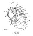
- FIG. 8Aillustrates a perspective exploded view of a screw system according to an embodiment of the present invention.
- FIG. 8Billustrates a perspective exploded view of a screw system according to an embodiment of the present invention.
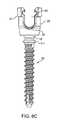
- FIG. 8Cillustrates a side elevational view of a screw system according to an embodiment of the present invention.
- FIG. 9Aillustrates a side exploded view of a screw/seat/cap and set screw combination.
- FIGS. 9B-9Dillustrate the combination system of FIG. 9A in unlocked, partially locked, and fully locked configurations.
- FIGS. 10A-10Cillustrate a screw/seat/pivoting rod combination system in exploded, connected but not deployed, and post-rotation configurations, respectively.
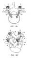
- FIGS. 11A and 11Bshow the installed device in top and perspective views, respectively.
- FIG. 12illustrates a side cross-sectional view of the seat with a seat-gripping instrument engaging the seat according to one aspect of the invention.
- systemwhen referring to a system of the present invention, most typically refers to a set of components which includes multiple bone stabilization components such as a superior, cephalad or rostral (towards the head) component configured for implantation into a superior vertebra of a vertebral motion segment and an inferior or caudal (towards the feet) component configured for implantation into an inferior vertebra of a vertebral motion segment.
- a pair of such component setsmay include one set of components configured for implantation into and stabilization of the left side of a vertebral segment and another set configured for the implantation into and stabilization of the right side of a vertebral segment.
- systemmay refer to two or more pairs of component sets, i.e., two or more left sets and/or two or more right sets of components.
- Such a multilevel systeminvolves stacking of component sets in which each set includes a superior component, an inferior component, and one or more medial components therebetween.
- the superior and inferior componentswhen operatively implanted, may be engaged or interface with each other in a manner that enables the treated spinal motion segment to mimic the function and movement of a healthy segment, or may simply fuse the segments such as to eliminate pain and/or promote or enhance healing.
- the interconnecting or interface meansinclude one or more structures or members that enables, limits and/or otherwise selectively controls spinal or other body motion.
- the structuresmay perform such functions by exerting various forces on the system components, and thus on the target vertebrae.
- the manner of coupling, interfacing, engagement or interconnection between the subject system componentsmay involve compression, distraction, rotation or torsion, or a combination thereof.
- the extent or degree of these forces or motions between the componentsmay be intraoperatively selected and/or adjusted to address the condition being treated, to accommodate the particular spinal anatomy into which the system is implanted, and to achieve the desired therapeutic result.
- the multiple componentsare mechanically coupled to each other by one or more interconnecting or interfacing means.
- componentsinterface, in a manner that constrains their relative movement and enables the treated segment to mimic the function or partial function and/or movement or partial movement of a healthy segment.
- spinal interconnecting meansis a dorsally positioned component, i.e., positioned posteriorly of the superior and inferior components, or may be a laterally positioned component, i.e., positioned to the outer side of the posterior and inferior components.
- the structuresmay include one or more struts and/or joints that provide for stabilized spinal motion.
- the various system embodimentsmay further include a band, interchangeably referred to as a ligament, which provides a tensioned relationship between the superior and inferior components and helps to maintain the proper relationship between the components.
- each of the inventive embodiments described hereinmay be employed in a percutaneous procedure, a mini-open procedure or an open procedure. Utilization of minimally invasive techniques can shorten the procedure's time and speed recovery by the patient. The application of these inventions in a minimally invasive manner is not a requirement.
- FIG. 2Aillustrates a perspective exploded and perspective view of a screw system which may be employed in an embodiment of the present invention.
- a screw system 20is shown having a screw 30 with threads 28 .
- the threads 28are appropriate for entering the bone of a patient.
- a ball end 32is shown, various other shapes may also be employed.
- a hex socket 34that is interconnected with a guidewire lumen (not shown) extends thru the general axial center of screw 30 , and also can extend through the retaining ring 22 , coupler 24 and seat 26 .
- the systemis suitable for being installed in a patient for treating at least one or more of the following: degenerative disc disease, spinal stenosis, spondylolisthesis, spinal deformities, fractures, pseudarthrosis, tumors, failed previous fusions, other vertebral segment trauma or diseases.
- the ball end 32 of screw 30is fitted into the bottom of the coupler 24 , which has a spherical interior shape, as will be described in greater detail below. If end 32 has a different shape, the shape of the interior of the bottom of the coupler 24 may be similarly complimentary. No matter the shape, when the ball end is fitted into the bottom end of end of the coupler 24 , the coupler 24 may be fitted into the “bucket-shaped” seat 26 . Retaining ring 22 ensures that coupler 24 does not escape from the interior of seat 26 , and is described in greater detail below.
- FIG. 2Billustrates a perspective view of a pivoting rod 40 which is employed in an embodiment of the present invention.
- the pivoting rod 40 in FIG. 2Bis shown to be straight, however, the invention is not so limited and a curved pivoting rod that conforms to the natural curve of the spine may be employed.
- the pivoting rod 40has a shaft 42 , a ball end 44 , and two pins 46 (one of which is not shown in FIG. 2B ) for insertion into the coupler 24 .
- the shaft 42may vary in length, or may be adjustable by the physician, either by a telescoping mechanism or by being cut to measure.
- the end of the shaft 42 opposite that of ball end 44may be straight, as shown, or may itself incorporate a ball end (not shown) or other type of end to enable trapping and capture in a seat of a pedicle screw system mounted to another spinal segment.
- the ball end 44need not actually be a ball, and may be a square or rectangular solid, or other such shape, so long as the shape allows rotation of the pivoting rod.
- the rod 40 and coupler 24include mating features adapted to connect together.
- sides 47 of the ball end, perpendicular to the pins 46are flattened.
- the flat sides 47 that are substantially perpendicular to the pins 46also assist in confining the range of motion of the rod substantially within a single plane.
- the flattened sides 47 surrounding the pins 46provide for a greater surface area that is in contact with the coupler 24 and thereby create an advantageous snug-fit engagement with the coupler. Because of the flattened sides 47 , when the rod 40 is inserted and the pins 46 are connected into the coupler 24 , the greater surface area of contact of the flattened sides 47 with the coupler provides for a snug-fit engagement with the coupler that would otherwise be the case with a rounded rod end. As a result, the rod advantageously does not pivot on its own in a direction away from the insertion angle or other angle at which the rod is positioned subsequent to insertion into the coupler. This feature facilitates insertion for the surgeon.
- additional flat portions 45are formed on the ball end 44 of the rod 40 as shown in FIG. 2B .
- the flat portions 45are substantially perpendicular to the flattened sides 47 on the ball end 44 .
- the pins 46are substantially parallel to the flat portions 45 .
- the flat portions 45face upwardly and downwardly and as a result provide a lower profile for the rod within the seat.
- the flat portions 45provide a flat contact surface for the set screw on the upper surface of the rod and a flat contact surface for the coupler on the bottom surface of the rod.
- the rodis not limited to having two flat portions 45 and/or two flattened sides 47 and any number and combination of flat portions 45 and sides 47 are within the scope of the present invention.
- FIG. 2Cillustrates a perspective exploded and perspective view of a closure mechanism 50 .
- the closure mechanismis shown as a cap and set screw system 50 which may be employed in an embodiment of the present invention. It should be noted that the closure mechanism is not limited to a cap and set screw combination as shown and described herein and various other closure mechanisms evident to a person having ordinary skill in the art are within the scope of the invention. Some examples of closure mechanisms include but are not limited to a threaded closure mechanism having external threads that engage with a threaded internal portion of the seat, a sliding closure mechanism, a compression fit closure mechanism, and a snap fit closure mechanism. The closure mechanism 50 , when fully installed in the seat 26 , secures the rod 40 against movement.
- the system 50includes a cap 48 and a set screw 52 .
- the cap 48includes a set screw receiving portion.
- the cap and set screware configured to close the top opening of the seat 26 .
- the external shape of the cap 48is substantially cylindrical.
- the cap 48includes a top surface and a bottom surface interconnected by an outer surface and an inner surface.
- the cap 48includes external flanges or features 54 , discussed in more detail below, and internal screw threads 56 .
- the set screw 52includes external screw threads 58 and a socket 62 for a driving tool, the socket 62 being substantially coaxial with the screw threads 58 .
- the set screw 52also includes a flange 51 at the bottom end of the set screw 52 .
- the flange 51is configured to extend outwardly from the circumference of the set screw to serve as a stop and to prevent the set screw 52 from being backed-out as the set screw is retracted upwardly with respect to the cap 48 .
- FIGS. 2A-2Cwould typically be employed in the following fashion: a first pedicle screw assembly would be installed in a patient, this first pedicle screw assembly having a hinge assembly that attaches to a proximal end of the pivoting rod. A second pedicle screw assembly would also be installed in a patient, this second pedicle screw assembly having a receiving cradle that accepts the distal end of the pivoting rod. Except for the hinge assembly and the receiving cradle, other parts of the screw assemblies may be the same and/or interchangeable. Each pedicle screw assembly also includes a set screw and cap assembly as described above and below.
- the pivoting rodmay include a dynamic element at some point along its length if desired, as described, e.g., in U.S. patent application Ser. No. 11/427,738, filed Jun. 29, 2006, U.S. patent application Ser. No. 10/970,366 filed Oct. 20, 2004, U.S. patent application Ser. No. 11/006,495 filed Dec. 6, 2004, U.S. patent application Ser. No. 11/033,452 filed Jan. 10, 2005, and U.S. patent application Ser. No. 11/436,407 filed on May 17, 2006, all of which are incorporated by reference herein in their entirety for all purposes.
- the pivoting rod 40is shown with integral pins 46 that are configured to snap-fit with the coupler 24 to secure the rod 40 in place and permit rotation of the rod.
- the pins 46are chamfered to ease the insertion of the pivoting rod by the clinician into the coupler and also ease removal of the pivoting rod from the coupler, if desired.
- Pinsare not the only means of attachment of the rod 42 to the coupler 24 and other variations and means are within the scope of the invention.
- the ball end 44 of the rodcan include cutout portions 43 that result in the ball end not having a completely spherical shape but permits attachment to and rotation relative to the coupler 24 . Another example is shown in FIG.
- FIG. 2Ea rod 40 is provided with a ball portion 41 having a bore 39 passing through it.
- the rod 40 of FIG. 2Eis positioned inside the bore 39 of the ball portion 41 such that the ball portion 41 is allowed to rotate and slide relative to the rod as indicated by the arrows in FIG. 2E .
- This embodimentadvantageously provides yet another degree of freedom of motion and facilitates installation by the surgeon.
- the embodiment of FIG. 2Eadvantageously permits the bone screw to be locked into position independently of rod and in another variation it permits the rod to be locked into position independently of the bone screw. More details of the independent lock down capability of this embodiment will be described in greater detail hereinbelow.
- FIG. 3 and FIG. 3AAn alternative way in which the pivoting rod 40 may be attached to the coupler that employs pins is shown in FIG. 3 and FIG. 3A .
- a set of two pins 64may be employed which mate with a corresponding set of holes 66 in the coupler.
- the pin 64may be spring-loaded with springs 68 .
- This spring-biased hinge pinallows pivoting of the rod and also allows the pin to move radially inward during insertion, and then “pop” out when in place. The pin may then be retracted for removal.
- the pinmay be permanently locked in place by injecting cement or glue or another such material into the travel volume of the pin.
- FIG. 4Another variation for the rod-end system is shown in FIG. 4 and the enlarged views of FIG. 4A-4C in which the pivoting rod 40 is attached to the coupler via pins 72 .
- pins 72may again be spring-biased but may be movable via action of a set screw 76 .
- pins 72are biased by springs 74 in a retracted state; i.e., they are not extended so as to engage or mate with holes in the coupler. Instead, a portion of the pins 72 extends into a threaded hole 70 within a proximal end of pivoting rod 40 , i.e., ball end 44 .
- a set screw 76When a set screw 76 , with conical distal surface 82 , is advanced into the threaded hole 70 , the distal surface 82 impinges on pins 72 and drives the same outward, such that they may engagedly mate with the holes in the coupler.
- the set screw 76may have a slot 78 and/or other tool engagement means (not shown) in its proximal (top) surface to allow for such driving. In this way, the extendable/retractable hinge pins extend after insertion to pivotally lock the pins in place.
- the extension and retractionmay be accomplished with hydraulics or pneumatics, rather than springs and set screws.
- a fluid injection portmay be provided which is integral, or not, to the pivoting rod.
- the pinsmay be permanently locked in place, if desired by the physician, by injecting cement or glue into the pin travel volume.
- FIG. 5Aa seat 26 and retaining ring 22 are shown in an exploded view.
- Retaining ring 22is shown with two projections 86 , also known as keys, which engage features on the seat 26 , to hold the coupler in place (the coupler is not shown in the figure for clarity).
- Ring rod channel bevels 84are shown on opposite ends of a diameter of the ring, adjacent the projections 86 , although in alternative embodiments they need not be adjacent. Ring rod channel bevels 84 are depressed areas along an upper surface of the circumference of the ring 22 , and assist in receiving the pivoting rod (also not shown for clarity).
- FIG. 8BAnother variation of the retaining ring 22 is shown in FIG. 8B .
- the retaining ring 22 of FIG. 8Bincludes a split such that the retaining ring 22 is approximately C-shaped.
- the split retaining ring 22snaps into place inside the seat 26 to secure the assembly.
- the seat 26includes an inner surface and an outer surface and a first end 81 and a second end 83 . At least one sidewall 79 extends between the first end 81 and the second end 83 forming a top opening at the first end 81 and at least one “U”-shaped void or rod channel 90 into which the pivoting rod may pivot when installed.
- a void or keyway 98is provided near the base of the seat to engage each projection 86 to orient the ring in a press-fit fashion with respect to the coupler and seat.
- the keyways 98are adjacent the rod channel bevels 84 and 94 because the keys 86 are adjacent the same; however, the keys and keyways need not be along the same diameter as the bevels.
- the ring and seat rod channel bevelsmay generally match each other in shape, pitch, angle, slope, etc., and assist in orienting the rod pivot arc as well as orienting the rod channel to receive the rod on the cradle or receiving assembly.
- the seat 26includes a closure mechanism receiving portion or a cap receiving portion 75 configured to receive a cap at the first end 81 and a coupler receiving portion 73 configured to receive a coupler.
- the coupler receiving portion 73includes a tapered ramp that corresponds to a tapered ramp on the coupler.
- the cap receiving portion 75includes a locking lug groove 88 that is provided near the top of the seat 26 to slidingly receive a corresponding locking lug or projection of the cap, described below. Cap rotation of, for example 90 degrees, secures the cap in place.
- the locking lug groove 88may further include an anti-rotation mechanism, such as a mechanical stop. In this way, the locking lugs may be fixed in the amount of rotation needed to secure them in place.
- a wing groove 92is also provided on the seat 26 , to slidingly receive and engage a corresponding wing lug or projection on the cap, as described below.
- the wing groove 92may also be provided with a mechanical stop that prevents further rotation of the wing within the wing groove similar to the locking lug groove.
- On the outside surface of the seat 26a flange 21 and two recesses 23 in opposed locations are formed as shown in FIGS. 5A and 5B .
- the flangehas an upper surface, lower surface and an outer surface.
- FIGS. 6A-6Bshow bottom and top perspective views, respectively, of the cap system 50 having cap 48 and set screw 52 .
- the cap 48incorporates at least one groove 112 and recess 113 for engagement with an inserter or driving tool to accomplish the partial rotation needed to lock the cap 48 into the seat 26 .
- the inserter or driving toolmay grip the cap for rotation: the recess provides room for “tangs” of the inserter tool, and the groove allows the “tangs” to clear the inner surfaces of the seat.
- a flange 116may be provided which is an annular projection at the top surface. The flange 116 acts as a mechanical stop, to limit the amount of insertion of the cap into the seat.
- the outer surface of the capincludes at least one seat-engagement feature for engagement with the cap-receiving portion of the seat.
- One seat-engagement feature on the capis at least one locking lug 110 that is provided in at least one location around the circumference of the cap 48 and extending from the outer surface of the cap. As shown in FIGS. 6A and 6B , two locking lugs 110 are provided on or are integral with the flange 116 opposite from one another. The locking lugs 110 are sized for insertion into the rod channel 90 . Also, the locking lugs 110 are configured to be rotatably inserted into the locking lug groove 88 in the seat 26 . Typically, the locking lugs 110 are first inserted into the rod channel 90 and then rotated into position inside the locking lug groove 88 .
- Another seat-engagement feature on the capis at least one wing 54 that is provided in at least one location around the circumference of the cap 48 extending outwardly from the outer surface of the cap. As shown in FIGS. 6A and 6B , two wings 54 are provided in opposed locations around the circumference of the cap 48 . The two wings 54 are aligned with the two locking lugs 110 wherein the wings 54 are located below locking lugs 110 . The wings are sized for insertion into the rod channel 90 . Also, the wings are configured to be rotatably inserted into the wing groove 92 .
- the cap 48is placed into the seat 26 with the two wings 54 and the two locking lugs 110 in alignment with the rod channel 90 such that the cap 48 drops into the seat until the flange 116 abuts a surface of the locking lug groove 88 .
- the cap 48is capable of being turned.
- Turning of the cap 48rotates the wings 54 and the locking lugs 110 into the wing grooves 92 and locking lug grooves 88 , respectively.
- a toolis used to engage the groove 112 and/or recess 113 of the cap to turn the cap 48 while it is inside the seat.
- the cap(not shown) is turned until rotation is stopped by a wall 85 located in the locking lug groove 88 against which the locking lugs 110 abut.
- a second locking wall(not shown) may also formed in the opposite locking lug groove generally diagonally from wall 85 .
- the degree of rotationis preferably approximately 90 degrees but the invention is not so limited and any degree of rotation is within the scope of the invention.
- the wallserves as an anti-rotation mechanism that prevents the cap from turning past a locked position. Other anti-rotation mechanisms may also be employed.
- a set screw 52 located inside the cap 48is tightened.
- the cap 48rises relative to the seat 26 , that is, the cap will move upwardly relative to the seat. This rise is arrested by the wings 54 , also known as wing lugs, contacting the upper surface of the wing groove 92 .
- the locking lugs alone or in conjunction with the wingsare employed to arrest the rise of the cap as the set screw is advanced and a force, resulting from the set screw being biased against the seat, is applied to the rod below the set screw.
- the cap 48counter-rotation of the cap 48 is prevented as the set screw is advanced and the locking lugs 110 rise relative to the seat 26 into a recess 89 or window formed inside the locking lug groove 88 as shown in FIG. 5B .
- the recess or window 89includes a stop 91 against which the locking lugs 110 abut to prevent counter-rotation.
- the locking lugs 110are substantially moved out of the locking lug groove 88 and they cannot be moved back into the groove 88 , and thus the cap cannot be removed, until the set screw is “backed off” and the cap drops or is “lowered” such that the locking lugs 110 reside again in the groove 88 .
- a corresponding recess 89 and a corresponding wall 91is formed in the other side of the cap receiving portion of the seat.
- the wing 54has a reverse angle surface 114 to inhibit spreading of the seat.
- the wing or wing lug groove 92 defined by the interior of seat 26slidingly receives the wing 54 or wing lug of the cap 48 , and the cap is locked into the seat when the cap is rotated, for example, by 90 degrees.
- the reverse angle surface 114keeps the seat 26 from splaying as the set screw 52 is rotated. In particular, as the set screw 52 rotation forces the cap upwards, the reverse angle surface 114 keeps the walls of the seat 26 from spreading outward. Otherwise, the forces of the cap upward movement would tend to spread the seat.
- the wingsmay snap into recesses of the wing lug groove 92 when an appropriate or predetermined degree of rotation has been achieved.
- Appropriate spring-loadingmay be employed to achieve this snapping feature.
- the bottom surface of the set screw 52includes a dome 118 that protrudes from the bottom surface of the set screw 52 .
- the feature 118contacts the rod 40 and creates a single point, line or smaller surface area of contact than would otherwise be the case between the cap system 50 and the rod 40 . This restrains less of the rod, allows some flexion and thus reduces the stiffness of the total device between the screws, leading to a better stress distribution through the construct, a lower stress concentration and enhanced fatigue performance.
- Examples of other features in the bottom surface of the set screwinclude but are not limited to any one or more of the following used alone or in combination: a dome, nipple, aperture, raised surface, and a dome with an aperture.
- FIG. 7shows additional details of the coupler 24 .
- the coupler 24generally has a bone screw receiving portion 128 and a rod receiving portion 122 .
- the rod receiving portionis shown in one variation as two upstanding forks 122 each of which has a receiving hole 66 for receiving the rod pin.
- the upstanding forks 122may have a tapered end, a closed end and/or an open end.
- FIG. 7shows a beveled region 124 radially exterior of each fork that lessens the amount of material in each fork, allowing greater amounts of flex.
- the coupler access bore hole 108provides access to the engagement means of the screw such as a hex socket.
- the inner surfaces of the rod receiving portion of the coupler and the screw head receiving portionare provided with grit-blasting to increase the surface roughness and resultant friction coefficient between the coupler and/or the rod.
- a lip 102is provided to mate with the retaining ring 22 .
- An approximately spherical bore 128 or screw head receiving portionis provided in the interior of the bottom of the coupler 24 that “snap-fits” over the head 32 of the screw 30 to allow a limited amount of rotation, for example 60 degrees of polyaxial rotation.
- the exterior surface of the coupler, exterior of the spherical bore 128may be a generally tapered ramp 126 .
- Slits 109may further be provided to allow circumferential compression around the screw head.
- the screwWith the cap in the cap-receiving portion of the seat and as the set screw is advanced within the cap, the screw contacts the rod and the cap rises relative to the seat until the wing lugs contact the upper surface of the wing lug groove and the cap is thereby biased into a locked configuration by the seat. Further advancement of the set screw exerts additional force onto the rod and it is transferred to the coupler and drives the coupler downward. As the set screw drives the coupler downward, e.g., through a force transmitted through the rod, the coupler is pushed downward, further into the seat. The tapered ramp of the coupler engages the corresponding tapered ramp in the seat.
- the coupleris radially compressed (which is possible because of the slits 109 ), thus gripping the screw head securely and simultaneously locking the bone screw and the rod into the desired position.
- the lockdown of the bone screwdoes not occur simultaneously with the lockdown of the rod.
- advancement of the set screwcontacts the ball portion 41 that slides and rotates with respect to the rod 40 .
- the contact with the set screwtransmits force directly to the coupler to effect the lockdown of the bone screw relative to the seat without locking down the rod relative to the seat, thereby, allowing the rod to slide and rotate with respect to the ball portion 41 .
- the advancement of the set screwcompresses the ball portion 41 locking the rod into position relative to the ball portion 41 after the bone screw has been locked.
- the advancement of the set screwcontacts the ball portion 41 and compresses the ball portion 41 to effect lockdown of the rod with respect to the seat without locking down the bone screw relative to the seat.
- Further advancement of the set screwtransmits force to the coupler to effect lockdown of the bone screw relative to the seat after the rod has been locked first.
- This independent lockdown mechanismpermits the selective lockdown of the rod relative to the seat and bone screw relative to the seat. Prior to the set screw being tightened, the bone screw and rod each were allowed movement relative to the seat. After the set screw is tightened, movement of both the bone screw and rod is generally eliminated.
- the cap set screw system in combination with the seat and couplerprovide a lockdown mechanism just described that operates between a locked configuration in which the rod and the bone screw are locked into position and an unlocked configuration in which the rod and the bone screw each have a range of motion relative the seat.
- the rodis not in vertical alignment with the seat, but instead, at least a portion of the rod extends through the rod channel 90 .
- the rodstill retains a range of motion while disposed in the rod channel and in the unlocked configuration.
- the systempermits some degree of motion of the rod and bone screw even when the system is in the locked configuration.
- the term “locked”is used to describe the restriction of motion of the rod and/or screw relative to the unlocked configuration. Also, the term “locked” is used with respect to the cap to describe the cap being seated inside the seat whether or not the set screw is advanced to the locked configuration to set the position of the rod and/or screw.
- a recess or keyway 106is provided in which a driving tool may be disposed to receive the keys or projections 86 on the retaining ring 22 .
- a “lead-in” ramp 104may be employed as a chamfered edge, providing a mechanical advantage to spread the coupler forks.
- the forksmay be configured to flex and also be resiliently biased. All of these features allow the hinge pins to more conveniently slide in and snap securely into the receiving holes 66 .
- the couplermay be generally the same and may further include a smooth surface 133 which incorporates a radiused edge which increases the contacting surface area and reduces high stress concentrations. In this way, the rod may be even more tightly received between the forks reducing the stress concentration on the rod and coupler.
- FIG. 8Ais a more expanded view of FIG. 2A .
- the basic four set of components, ring, coupler, seat, and screwmay be the same or similar for both the hinged assembly and the receiving cradle.
- the seatsnaps onto the screw, the coupler is placed into the seat, and the ring is press-fitted into the seat to retain the coupler.
- the seat 26may have an internal tapered bore to hold the coupler and screw in a snug configuration.
- FIG. 8Bis a perspective view of another variation of the present invention showing the screw 30 , seat 26 , coupler 24 and retaining ring 22 in an exploded view
- FIG. 8Cis a side-elevational view of the system wherein like elements are referenced with like numerals.
- the screwincludes a flange 111 located below the screw head 32 .
- the flange 111extends outwardly from and around the screw; however, the invention is not so limited and the flange 111 may be noncontinuous forming two or more flange pieces around the circumference of the screw for example.
- the flange 111is configured to serve as a stop and prevent the screw from being inserted into the bone beyond the flange.
- the flange 111is sufficiently broad that it does not dig into the bone as the screw is attempted to be advanced beyond the flange-to-bone contact.
- the flangesurrounds the circumference of the screw at a distance below the screw head that permits maximum angular and polyaxial adjustment and rotation of the seat.
- the flange 111may be formed or located closer to the screw head to constrain the degree of freedom of the polyaxial adjustment and rotation of the seat if it is so desired.
- the flangeadvantageously provides a tactile signal to the clinician when the flange 111 abuts the bone when inserting the screw into the bone.
- the clinicianmust verify advancement of the screw under fluoroscopy to avoid the screw head being completely driven to the surface of the bone which would impede the ability of the polyaxial seat to rotate and angulate freely. Because the flanged screw facilitates screw insertion, it is particularly advantageous in minimally invasive procedures.
- the retaining ring 22 of FIG. 8Bincludes a split such that the retaining ring 22 is approximately C-shaped.
- the bone screw head 32is inserted into the coupler 24 and the split retaining ring 22 is inserted into the seat 26 .
- the screw and coupler assemblyis passed through the top of the seat 26 and attached together to complete assembly of the screw system.
- FIGS. 9A-9DVarious methods of use are now described with respect to FIGS. 9A-9D .
- the set screw 52is partially advanced into the cap 48 and the same is situated above the seat 26 as shown in FIG. 9A .
- the locking lugs and the wings of cap 48are half in-the-page and half out-of-the page. In the same way, one rod channel is below the page and the other is above the page.
- FIG. 9Bshows an approximately 45 degrees turn counter-clockwise. In this configuration, the cap is partially locked onto the seat.
- FIG. 9Dthe cap has been rotated 90 degrees with respect to the orientation of FIG. 9B , and the cap is now locked onto the seat.
- a mechanical stop 91may be employed to prevent further rotation.
- FIG. 10A-10Cillustrates a method of rod installation which is typically accomplished just prior to the cap and set screw fixation shown in FIG. 9A-9D .
- Pivoting rod system 40is disposed in the screw system 20 .
- the chamfered nature of pins 46eases the installation into the receiving holes of the coupler, as does the ramp 104 on the coupler.
- FIGS. 10A and 10Billustrate the rod 40 in a vertical orientation that is substantially parallel to the screw orientation
- the rod 40may be oriented 90 degrees in FIGS. 10A and 10B such that it is substantially perpendicular to the screw orientation and be capable of insertion into the seat.
- the rod 40can be oriented at any angle relative to the screw that permits insertion into the seat.
- the screw system 20allows for the bone screw to be first set into the bone and then, following the insertion of the bone screw, the rod is attached in any of the various orientations of the rod relative to the screw just discussed.
- the systemis versatile such that the rod may be attached first to the seat in the various orientations of the rod relative to the screw just described and then the entire system 20 (the rod-plus-screw combination) set into the bone simultaneously using instrumentation that grips the seat 26 at the flange 21 and/or recesses 23 , for example, or the rod 40 itself.
- the capis seated and locked. Prior to the locked configuration, that is a complete tightening of the set screw, and with or without the cap in position, the system retains two levels of freedom of motion.
- the rodis free to be adjusted with respect to the seat and secondly, the seat is free to be adjusted relative to the screw.
- both the rod and the screwretain a degree of motion relative to seat, with or without the cap in place, which allows the clinician to custom orientate the seat with respect to the bone screw.
- the freedom of motionalso permits the clinician to custom orientate the rod with respect to the seat with the system deployed inside the patient and in the unlocked configuration. This freedom of motion advantageously provides the surgeon with a much-needed, increased ease of implantation.
- FIGS. 11A and 11Bshow a typical installation environment of the devices in two spinal segments of a patient.
- FIG. 12illustrates a side cross-sectional view of the seat 26 with a sectional view of a seat-gripping instrument 130 engaging the seat.
- the flange 21 of the seat 26includes an upper surface 136 , an outer surface 138 and a lower surface 140 and extends outwardly from the outer surface of the seat.
- FIG. 12shows a single circumferentially continuous flange 21 , the invention is not so limited and more than one flange may be formed.
- the instrument 130includes a first portion 132 and a second portion 134 interconnected with a handle portion (not shown).
- the first portion 132 of the instrumentis configured to contact at least a portion of the flange outer surface 138 and/or at least a portion of the flange lower surface 140 .
- the second portion 134 of the instrumentis configured to slide with respect to the first portion 132 and contact the upper surface 136 of the flange as shown in FIG. 12 .
- the second portion 134is advanced to tighten against the upper surface and securely retain the seat within the instrument 130 for deployment into the patient.
Landscapes
- Health & Medical Sciences (AREA)
- Orthopedic Medicine & Surgery (AREA)
- Life Sciences & Earth Sciences (AREA)
- Neurology (AREA)
- Surgery (AREA)
- Heart & Thoracic Surgery (AREA)
- Engineering & Computer Science (AREA)
- Biomedical Technology (AREA)
- Nuclear Medicine, Radiotherapy & Molecular Imaging (AREA)
- Medical Informatics (AREA)
- Molecular Biology (AREA)
- Animal Behavior & Ethology (AREA)
- General Health & Medical Sciences (AREA)
- Public Health (AREA)
- Veterinary Medicine (AREA)
- Surgical Instruments (AREA)
- Prostheses (AREA)
Abstract
Description
Claims (68)
Priority Applications (13)
| Application Number | Priority Date | Filing Date | Title |
|---|---|---|---|
| US11/726,093US8267969B2 (en) | 2004-10-20 | 2007-03-20 | Screw systems and methods for use in stabilization of bone structures |
| US11/801,194US20070225712A1 (en) | 2004-10-20 | 2007-05-09 | Systems and methods for posterior dynamic stabilization of the spine |
| US11/801,186US20070219556A1 (en) | 2004-10-20 | 2007-05-09 | System and methods for posterior dynamic stabilization of the spine |
| US11/801,319US20070225713A1 (en) | 2004-10-20 | 2007-05-09 | Systems and methods for posterior dynamic stabilization of the spine |
| EP08727028AEP2142119A4 (en) | 2007-03-20 | 2008-03-20 | SCREWING SYSTEMS AND METHOD FOR USE IN THE STABILIZATION OF BONE STRUCTURES |
| CA002682180ACA2682180A1 (en) | 2007-03-20 | 2008-03-20 | Screw systems and methods for use in stabilization of bone structures |
| AU2008229323AAU2008229323A1 (en) | 2007-03-20 | 2008-03-20 | Screw systems and methods for use in stabilization of bone structures |
| PCT/US2008/003677WO2008115549A1 (en) | 2007-03-20 | 2008-03-20 | Screw systems and methods for use in stabilization of bone structures |
| US12/079,676US8535352B2 (en) | 2004-10-20 | 2008-03-28 | Multi-level minimally invasive spinal stabilization system |
| PCT/US2008/079580WO2009049206A2 (en) | 2005-07-22 | 2008-10-10 | Offset connector for a spinal stabilization rod |
| US12/249,203US20090036929A1 (en) | 2005-07-22 | 2008-10-10 | Offset connector for a spinal stabilization rod |
| IL201031AIL201031A0 (en) | 2007-03-20 | 2009-09-17 | Screw systems and methods for use in stabilization of bone structures |
| US12/966,807US8551142B2 (en) | 2004-10-20 | 2010-12-13 | Methods for stabilization of bone structures |
Applications Claiming Priority (9)
| Application Number | Priority Date | Filing Date | Title |
|---|---|---|---|
| US10/970,366US8162985B2 (en) | 2004-10-20 | 2004-10-20 | Systems and methods for posterior dynamic stabilization of the spine |
| US11/006,495US8075595B2 (en) | 2004-10-20 | 2004-12-06 | Systems and methods for posterior dynamic stabilization of the spine |
| US11/033,452US7998175B2 (en) | 2004-10-20 | 2005-01-10 | Systems and methods for posterior dynamic stabilization of the spine |
| US70166005P | 2005-07-22 | 2005-07-22 | |
| US11/362,366US8226690B2 (en) | 2005-07-22 | 2006-02-23 | Systems and methods for stabilization of bone structures |
| US11/436,407US8025680B2 (en) | 2004-10-20 | 2006-05-17 | Systems and methods for posterior dynamic stabilization of the spine |
| US11/427,738US7935134B2 (en) | 2004-10-20 | 2006-06-29 | Systems and methods for stabilization of bone structures |
| US11/586,849US20070239159A1 (en) | 2005-07-22 | 2006-10-25 | Systems and methods for stabilization of bone structures |
| US11/726,093US8267969B2 (en) | 2004-10-20 | 2007-03-20 | Screw systems and methods for use in stabilization of bone structures |
Related Parent Applications (3)
| Application Number | Title | Priority Date | Filing Date |
|---|---|---|---|
| US42773606AContinuation-In-Part | 2004-10-20 | 2006-06-29 | |
| US11/427,738Continuation-In-PartUS7935134B2 (en) | 2004-10-20 | 2006-06-29 | Systems and methods for stabilization of bone structures |
| US11/586,849Continuation-In-PartUS20070239159A1 (en) | 2004-10-20 | 2006-10-25 | Systems and methods for stabilization of bone structures |
Related Child Applications (6)
| Application Number | Title | Priority Date | Filing Date |
|---|---|---|---|
| US11/427,738Continuation-In-PartUS7935134B2 (en) | 2004-10-20 | 2006-06-29 | Systems and methods for stabilization of bone structures |
| US11/801,186Continuation-In-PartUS20070219556A1 (en) | 2004-10-20 | 2007-05-09 | System and methods for posterior dynamic stabilization of the spine |
| US11/801,319Continuation-In-PartUS20070225713A1 (en) | 2004-10-20 | 2007-05-09 | Systems and methods for posterior dynamic stabilization of the spine |
| US11/801,194Continuation-In-PartUS20070225712A1 (en) | 2004-10-20 | 2007-05-09 | Systems and methods for posterior dynamic stabilization of the spine |
| US12/079,676Continuation-In-PartUS8535352B2 (en) | 2004-10-20 | 2008-03-28 | Multi-level minimally invasive spinal stabilization system |
| US12/966,807DivisionUS8551142B2 (en) | 2004-10-20 | 2010-12-13 | Methods for stabilization of bone structures |
Publications (2)
| Publication Number | Publication Date |
|---|---|
| US20070167949A1 US20070167949A1 (en) | 2007-07-19 |
| US8267969B2true US8267969B2 (en) | 2012-09-18 |
Family
ID=39668829
Family Applications (2)
| Application Number | Title | Priority Date | Filing Date |
|---|---|---|---|
| US11/726,093Active2027-10-10US8267969B2 (en) | 2004-10-20 | 2007-03-20 | Screw systems and methods for use in stabilization of bone structures |
| US12/966,807Expired - LifetimeUS8551142B2 (en) | 2004-10-20 | 2010-12-13 | Methods for stabilization of bone structures |
Family Applications After (1)
| Application Number | Title | Priority Date | Filing Date |
|---|---|---|---|
| US12/966,807Expired - LifetimeUS8551142B2 (en) | 2004-10-20 | 2010-12-13 | Methods for stabilization of bone structures |
Country Status (6)
| Country | Link |
|---|---|
| US (2) | US8267969B2 (en) |
| EP (1) | EP2142119A4 (en) |
| AU (1) | AU2008229323A1 (en) |
| CA (1) | CA2682180A1 (en) |
| IL (1) | IL201031A0 (en) |
| WO (1) | WO2008115549A1 (en) |
Cited By (67)
| Publication number | Priority date | Publication date | Assignee | Title |
|---|---|---|---|---|
| US20090125047A1 (en)* | 2005-07-22 | 2009-05-14 | Joey Camia Reglos | Tissue splitter |
| US20120179209A1 (en)* | 2010-12-10 | 2012-07-12 | Lutz Biedermann | Receiving part for receiving a rod for coupling the rod to a bone anchoring element and a bone anchoring device |
| US20130079826A1 (en)* | 2011-09-23 | 2013-03-28 | Peter M. Simonson | Spinal rod and bone screw caps for spinal systems assemblies |
| US8551142B2 (en) | 2004-10-20 | 2013-10-08 | Exactech, Inc. | Methods for stabilization of bone structures |
| US20140005725A1 (en)* | 2012-07-02 | 2014-01-02 | James C. Robinson | Bone screw coupling assembly |
| US9050139B2 (en) | 2004-02-27 | 2015-06-09 | Roger P. Jackson | Orthopedic implant rod reduction tool set and method |
| US9055978B2 (en) | 2004-02-27 | 2015-06-16 | Roger P. Jackson | Orthopedic implant rod reduction tool set and method |
| US9364262B2 (en) | 2012-07-02 | 2016-06-14 | Spectrum Spine Ip Holdings, Llc | Bone screw coupling assembly |
| US20160331413A1 (en)* | 2014-06-13 | 2016-11-17 | Orthopediatrics Corp. | Bottom loaded pedicle screw |
| US9498231B2 (en) | 2011-06-27 | 2016-11-22 | Board Of Regents Of The University Of Nebraska | On-board tool tracking system and methods of computer assisted surgery |
| US9532815B2 (en) | 2004-02-27 | 2017-01-03 | Roger P. Jackson | Spinal fixation tool set and method |
| US9861495B2 (en) | 2013-03-14 | 2018-01-09 | Raed M. Ali, M.D., Inc. | Lateral interbody fusion devices, systems and methods |
| US9918751B2 (en) | 2004-02-27 | 2018-03-20 | Roger P. Jackson | Tool system for dynamic spinal implants |
| US9980750B2 (en) | 2011-03-18 | 2018-05-29 | Raed M. Ali, M.D., Inc. | Spinal fusion devices and systems |
| US10039577B2 (en) | 2004-11-23 | 2018-08-07 | Roger P Jackson | Bone anchor receiver with horizontal radiused tool attachment structures and parallel planar outer surfaces |
| US10105149B2 (en) | 2013-03-15 | 2018-10-23 | Board Of Regents Of The University Of Nebraska | On-board tool tracking system and methods of computer assisted surgery |
| EP3441028A1 (en) | 2017-08-08 | 2019-02-13 | Biedermann Technologies GmbH & Co. KG | Receiving part and instrument for holding the receiving part |
| US10219811B2 (en) | 2011-06-27 | 2019-03-05 | Board Of Regents Of The University Of Nebraska | On-board tool tracking system and methods of computer assisted surgery |
| US10299839B2 (en) | 2003-12-16 | 2019-05-28 | Medos International Sárl | Percutaneous access devices and bone anchor assemblies |
| US10349982B2 (en) | 2011-11-01 | 2019-07-16 | Nuvasive Specialized Orthopedics, Inc. | Adjustable magnetic devices and methods of using same |
| US10478232B2 (en) | 2009-04-29 | 2019-11-19 | Nuvasive Specialized Orthopedics, Inc. | Interspinous process device and method |
| US10485588B2 (en) | 2004-02-27 | 2019-11-26 | Nuvasive, Inc. | Spinal fixation tool attachment structure |
| US10617453B2 (en) | 2015-10-16 | 2020-04-14 | Nuvasive Specialized Orthopedics, Inc. | Adjustable devices for treating arthritis of the knee |
| US10646262B2 (en) | 2011-02-14 | 2020-05-12 | Nuvasive Specialized Orthopedics, Inc. | System and method for altering rotational alignment of bone sections |
| US10660675B2 (en) | 2010-06-30 | 2020-05-26 | Nuvasive Specialized Orthopedics, Inc. | External adjustment device for distraction device |
| US10687962B2 (en) | 2013-03-14 | 2020-06-23 | Raed M. Ali, M.D., Inc. | Interbody fusion devices, systems and methods |
| US10729470B2 (en) | 2008-11-10 | 2020-08-04 | Nuvasive Specialized Orthopedics, Inc. | External adjustment device for distraction device |
| US10743794B2 (en) | 2011-10-04 | 2020-08-18 | Nuvasive Specialized Orthopedics, Inc. | Devices and methods for non-invasive implant length sensing |
| US10751094B2 (en) | 2013-10-10 | 2020-08-25 | Nuvasive Specialized Orthopedics, Inc. | Adjustable spinal implant |
| US10835290B2 (en) | 2015-12-10 | 2020-11-17 | Nuvasive Specialized Orthopedics, Inc. | External adjustment device for distraction device |
| US10918425B2 (en) | 2016-01-28 | 2021-02-16 | Nuvasive Specialized Orthopedics, Inc. | System and methods for bone transport |
| US10987228B2 (en) | 2011-03-18 | 2021-04-27 | Raed M. Ali, M.D., Inc. | Devices and methods for transpedicular stabilization of the spine |
| US11116574B2 (en) | 2006-06-16 | 2021-09-14 | Board Of Regents Of The University Of Nebraska | Method and apparatus for computer aided surgery |
| US11147597B2 (en) | 2004-02-27 | 2021-10-19 | Roger P Jackson | Dynamic spinal stabilization assemblies, tool set and method |
| US11191579B2 (en) | 2012-10-29 | 2021-12-07 | Nuvasive Specialized Orthopedics, Inc. | Adjustable devices for treating arthritis of the knee |
| US11202707B2 (en) | 2008-03-25 | 2021-12-21 | Nuvasive Specialized Orthopedics, Inc. | Adjustable implant system |
| US11207110B2 (en) | 2009-09-04 | 2021-12-28 | Nuvasive Specialized Orthopedics, Inc. | Bone growth device and method |
| US11234849B2 (en) | 2006-10-20 | 2022-02-01 | Nuvasive Specialized Orthopedics, Inc. | Adjustable implant and method of use |
| US11241261B2 (en) | 2005-09-30 | 2022-02-08 | Roger P Jackson | Apparatus and method for soft spinal stabilization using a tensionable cord and releasable end structure |
| US11246694B2 (en) | 2014-04-28 | 2022-02-15 | Nuvasive Specialized Orthopedics, Inc. | System for informational magnetic feedback in adjustable implants |
| US11304729B2 (en) | 2009-02-23 | 2022-04-19 | Nuvasive Specialized Orthhopedics, Inc. | Non-invasive adjustable distraction system |
| USRE49061E1 (en) | 2012-10-18 | 2022-05-10 | Nuvasive Specialized Orthopedics, Inc. | Intramedullary implants for replacing lost bone |
| US11357549B2 (en) | 2004-07-02 | 2022-06-14 | Nuvasive Specialized Orthopedics, Inc. | Expandable rod system to treat scoliosis and method of using the same |
| US11357547B2 (en) | 2014-10-23 | 2022-06-14 | Nuvasive Specialized Orthopedics Inc. | Remotely adjustable interactive bone reshaping implant |
| US11419642B2 (en) | 2003-12-16 | 2022-08-23 | Medos International Sarl | Percutaneous access devices and bone anchor assemblies |
| US11439449B2 (en) | 2014-12-26 | 2022-09-13 | Nuvasive Specialized Orthopedics, Inc. | Systems and methods for distraction |
| US11577097B2 (en) | 2019-02-07 | 2023-02-14 | Nuvasive Specialized Orthopedics, Inc. | Ultrasonic communication in medical devices |
| US11589901B2 (en) | 2019-02-08 | 2023-02-28 | Nuvasive Specialized Orthopedics, Inc. | External adjustment device |
| US11612416B2 (en) | 2015-02-19 | 2023-03-28 | Nuvasive Specialized Orthopedics, Inc. | Systems and methods for vertebral adjustment |
| US11627995B2 (en) | 2020-12-21 | 2023-04-18 | Warsaw Orthopedic, Inc. | Locking-cap module and connector |
| US11627992B2 (en) | 2020-12-21 | 2023-04-18 | Warsaw Orthopedic, Inc. | Locking-cap module and connector |
| US11696836B2 (en) | 2013-08-09 | 2023-07-11 | Nuvasive, Inc. | Lordotic expandable interbody implant |
| US20230240724A1 (en)* | 2019-05-22 | 2023-08-03 | Nuvasive, Inc. | Posterior spinal fixation screws |
| US11737787B1 (en) | 2021-05-27 | 2023-08-29 | Nuvasive, Inc. | Bone elongating devices and methods of use |
| US11766252B2 (en) | 2013-07-31 | 2023-09-26 | Nuvasive Specialized Orthopedics, Inc. | Noninvasively adjustable suture anchors |
| US11801187B2 (en) | 2016-02-10 | 2023-10-31 | Nuvasive Specialized Orthopedics, Inc. | Systems and methods for controlling multiple surgical variables |
| US11806054B2 (en) | 2021-02-23 | 2023-11-07 | Nuvasive Specialized Orthopedics, Inc. | Adjustable implant, system and methods |
| US11839410B2 (en) | 2012-06-15 | 2023-12-12 | Nuvasive Inc. | Magnetic implants with improved anatomical compatibility |
| US11857226B2 (en) | 2013-03-08 | 2024-01-02 | Nuvasive Specialized Orthopedics | Systems and methods for ultrasonic detection of device distraction |
| US11871974B2 (en) | 2007-10-30 | 2024-01-16 | Nuvasive Specialized Orthopedics, Inc. | Skeletal manipulation method |
| US11911117B2 (en) | 2011-06-27 | 2024-02-27 | Board Of Regents Of The University Of Nebraska | On-board tool tracking system and methods of computer assisted surgery |
| US11925389B2 (en) | 2008-10-13 | 2024-03-12 | Nuvasive Specialized Orthopedics, Inc. | Spinal distraction system |
| US11957391B2 (en) | 2021-11-01 | 2024-04-16 | Warsaw Orthopedic, Inc. | Bone screw having an overmold of a shank |
| US12023073B2 (en) | 2021-08-03 | 2024-07-02 | Nuvasive Specialized Orthopedics, Inc. | Adjustable implant |
| US12114898B2 (en) | 2020-11-19 | 2024-10-15 | K2M, Inc. | Modular head assembly for spinal fixation |
| US12213708B2 (en) | 2020-09-08 | 2025-02-04 | Nuvasive Specialized Orthopedics, Inc. | Remote control module for adjustable implants |
| US12262921B2 (en) | 2020-06-26 | 2025-04-01 | K2M, Inc. | Modular head assembly |
Families Citing this family (120)
| Publication number | Priority date | Publication date | Assignee | Title |
|---|---|---|---|---|
| US7833250B2 (en) | 2004-11-10 | 2010-11-16 | Jackson Roger P | Polyaxial bone screw with helically wound capture connection |
| US8353932B2 (en)* | 2005-09-30 | 2013-01-15 | Jackson Roger P | Polyaxial bone anchor assembly with one-piece closure, pressure insert and plastic elongate member |
| US10258382B2 (en) | 2007-01-18 | 2019-04-16 | Roger P. Jackson | Rod-cord dynamic connection assemblies with slidable bone anchor attachment members along the cord |
| US10729469B2 (en) | 2006-01-09 | 2020-08-04 | Roger P. Jackson | Flexible spinal stabilization assembly with spacer having off-axis core member |
| US8292926B2 (en) | 2005-09-30 | 2012-10-23 | Jackson Roger P | Dynamic stabilization connecting member with elastic core and outer sleeve |
| US8876868B2 (en) | 2002-09-06 | 2014-11-04 | Roger P. Jackson | Helical guide and advancement flange with radially loaded lip |
| WO2006052796A2 (en) | 2004-11-10 | 2006-05-18 | Jackson Roger P | Helical guide and advancement flange with break-off extensions |
| US6716214B1 (en) | 2003-06-18 | 2004-04-06 | Roger P. Jackson | Polyaxial bone screw with spline capture connection |
| US7377923B2 (en) | 2003-05-22 | 2008-05-27 | Alphatec Spine, Inc. | Variable angle spinal screw assembly |
| US8377102B2 (en) | 2003-06-18 | 2013-02-19 | Roger P. Jackson | Polyaxial bone anchor with spline capture connection and lower pressure insert |
| US7776067B2 (en) | 2005-05-27 | 2010-08-17 | Jackson Roger P | Polyaxial bone screw with shank articulation pressure insert and method |
| US7967850B2 (en) | 2003-06-18 | 2011-06-28 | Jackson Roger P | Polyaxial bone anchor with helical capture connection, insert and dual locking assembly |
| US8926670B2 (en) | 2003-06-18 | 2015-01-06 | Roger P. Jackson | Polyaxial bone screw assembly |
| US7766915B2 (en) | 2004-02-27 | 2010-08-03 | Jackson Roger P | Dynamic fixation assemblies with inner core and outer coil-like member |
| US8398682B2 (en) | 2003-06-18 | 2013-03-19 | Roger P. Jackson | Polyaxial bone screw assembly |
| US8257398B2 (en) | 2003-06-18 | 2012-09-04 | Jackson Roger P | Polyaxial bone screw with cam capture |
| US8137386B2 (en) | 2003-08-28 | 2012-03-20 | Jackson Roger P | Polyaxial bone screw apparatus |
| US7527638B2 (en) | 2003-12-16 | 2009-05-05 | Depuy Spine, Inc. | Methods and devices for minimally invasive spinal fixation element placement |
| EP1814472B1 (en)* | 2004-09-08 | 2018-10-24 | NuVasive, Inc. | Systems for performing spinal fixation |
| US7651502B2 (en) | 2004-09-24 | 2010-01-26 | Jackson Roger P | Spinal fixation tool set and method for rod reduction and fastener insertion |
| US8226690B2 (en) | 2005-07-22 | 2012-07-24 | The Board Of Trustees Of The Leland Stanford Junior University | Systems and methods for stabilization of bone structures |
| US7604655B2 (en) | 2004-10-25 | 2009-10-20 | X-Spine Systems, Inc. | Bone fixation system and method for using the same |
| WO2006047711A2 (en) | 2004-10-25 | 2006-05-04 | Alphaspine, Inc. | Pedicle screw systems and methods |
| US8926672B2 (en) | 2004-11-10 | 2015-01-06 | Roger P. Jackson | Splay control closure for open bone anchor |
| US9216041B2 (en) | 2009-06-15 | 2015-12-22 | Roger P. Jackson | Spinal connecting members with tensioned cords and rigid sleeves for engaging compression inserts |
| US7875065B2 (en) | 2004-11-23 | 2011-01-25 | Jackson Roger P | Polyaxial bone screw with multi-part shank retainer and pressure insert |
| US8308782B2 (en) | 2004-11-23 | 2012-11-13 | Jackson Roger P | Bone anchors with longitudinal connecting member engaging inserts and closures for fixation and optional angulation |
| US9980753B2 (en) | 2009-06-15 | 2018-05-29 | Roger P Jackson | pivotal anchor with snap-in-place insert having rotation blocking extensions |
| US9168069B2 (en) | 2009-06-15 | 2015-10-27 | Roger P. Jackson | Polyaxial bone anchor with pop-on shank and winged insert with lower skirt for engaging a friction fit retainer |
| US8444681B2 (en) | 2009-06-15 | 2013-05-21 | Roger P. Jackson | Polyaxial bone anchor with pop-on shank, friction fit retainer and winged insert |
| US7901437B2 (en) | 2007-01-26 | 2011-03-08 | Jackson Roger P | Dynamic stabilization member with molded connection |
| US10076361B2 (en) | 2005-02-22 | 2018-09-18 | Roger P. Jackson | Polyaxial bone screw with spherical capture, compression and alignment and retention structures |
| US7794481B2 (en)* | 2005-04-22 | 2010-09-14 | Warsaw Orthopedic, Inc. | Force limiting coupling assemblies for spinal implants |
| US7717943B2 (en) | 2005-07-29 | 2010-05-18 | X-Spine Systems, Inc. | Capless multiaxial screw and spinal fixation assembly and method |
| US7625394B2 (en)* | 2005-08-05 | 2009-12-01 | Warsaw Orthopedic, Inc. | Coupling assemblies for spinal implants |
| KR100741293B1 (en)* | 2005-08-30 | 2007-07-23 | 주식회사 솔고 바이오메디칼 | Spinal Pedicle Screw |
| US8105368B2 (en) | 2005-09-30 | 2012-01-31 | Jackson Roger P | Dynamic stabilization connecting member with slitted core and outer sleeve |
| WO2007041702A2 (en) | 2005-10-04 | 2007-04-12 | Alphaspine, Inc. | Pedicle screw system with provisional locking aspects |
| US8097025B2 (en) | 2005-10-25 | 2012-01-17 | X-Spine Systems, Inc. | Pedicle screw system configured to receive a straight or curved rod |
| US8100946B2 (en) | 2005-11-21 | 2012-01-24 | Synthes Usa, Llc | Polyaxial bone anchors with increased angulation |
| US8096996B2 (en) | 2007-03-20 | 2012-01-17 | Exactech, Inc. | Rod reducer |
| US8475498B2 (en) | 2007-01-18 | 2013-07-02 | Roger P. Jackson | Dynamic stabilization connecting member with cord connection |
| US8366745B2 (en) | 2007-05-01 | 2013-02-05 | Jackson Roger P | Dynamic stabilization assembly having pre-compressed spacers with differential displacements |
| US10792074B2 (en) | 2007-01-22 | 2020-10-06 | Roger P. Jackson | Pivotal bone anchor assemly with twist-in-place friction fit insert |
| US20080200956A1 (en)* | 2007-02-19 | 2008-08-21 | Tutela Medicus, Llc | Low Profile Orthopedic Fastener Assembly Having Enhanced Flexibility |
| US10383660B2 (en) | 2007-05-01 | 2019-08-20 | Roger P. Jackson | Soft stabilization assemblies with pretensioned cords |
| US8979904B2 (en) | 2007-05-01 | 2015-03-17 | Roger P Jackson | Connecting member with tensioned cord, low profile rigid sleeve and spacer with torsion control |
| US8221471B2 (en)* | 2007-05-24 | 2012-07-17 | Aesculap Implant Systems, Llc | Pedicle screw fixation system |
| PL2170192T3 (en)* | 2007-07-20 | 2011-07-29 | Synthes Gmbh | Polyaxial bone fixation element |
| US9439681B2 (en) | 2007-07-20 | 2016-09-13 | DePuy Synthes Products, Inc. | Polyaxial bone fixation element |
| US20090177239A1 (en)* | 2007-08-06 | 2009-07-09 | Michael Castro | Cervical plate instrument kit |
| US8038701B2 (en)* | 2007-10-22 | 2011-10-18 | K2M, Inc. | Uni-planar, taper lock bone screw |
| US20090105756A1 (en)* | 2007-10-23 | 2009-04-23 | Marc Richelsoph | Spinal implant |
| US8287576B2 (en)* | 2007-10-23 | 2012-10-16 | K2M, Inc. | Mono-axial, taper lock bone screw |
| US8998958B2 (en)* | 2007-12-20 | 2015-04-07 | Aesculap Implant Systems, Llc | Locking device introducer instrument |
| US8439922B1 (en) | 2008-02-06 | 2013-05-14 | NiVasive, Inc. | Systems and methods for holding and implanting bone anchors |
| US9060813B1 (en) | 2008-02-29 | 2015-06-23 | Nuvasive, Inc. | Surgical fixation system and related methods |
| AU2010260521C1 (en) | 2008-08-01 | 2013-08-01 | Roger P. Jackson | Longitudinal connecting member with sleeved tensioned cords |
| EP2355725B1 (en) | 2008-09-05 | 2017-03-08 | Synthes GmbH | Bone fixation assembly |
| US9603629B2 (en) | 2008-09-09 | 2017-03-28 | Intelligent Implant Systems Llc | Polyaxial screw assembly |
| JP5815407B2 (en) | 2008-09-12 | 2015-11-17 | ジンテス ゲゼルシャフト ミット ベシュレンクテル ハフツング | Spinal stabilization and guided fixation system |
| KR20110081208A (en) | 2008-09-29 | 2011-07-13 | 신세스 게엠바하 | Multi-Axis Bottom-Loading Screw and Rod Assemblies |
| US8080040B2 (en)* | 2008-10-29 | 2011-12-20 | Warsaw Orthopedic, Inc. | Anchor with two member securing mechanism for attaching an elongated member to a bone |
| US20100114168A1 (en)* | 2008-10-30 | 2010-05-06 | Warsaw Orthopedic, Inc. | Anchor with non-threaded securing mechanism to attach an elongated member to a bone |
| CA2742399A1 (en) | 2008-11-03 | 2010-06-03 | Dustin M. Harvey | Uni-planar bone fixation assembly |
| US9005260B2 (en)* | 2009-01-15 | 2015-04-14 | Aesculap Implant Systems, Llc | Receiver body for spinal fixation system |
| US9482260B1 (en) | 2009-02-24 | 2016-11-01 | William R Krause | Flexible fastening device for industrial use |
| KR20120013312A (en) | 2009-04-15 | 2012-02-14 | 신세스 게엠바하 | Orthodontic Connectors for Spinal Structures |
| US11229457B2 (en) | 2009-06-15 | 2022-01-25 | Roger P. Jackson | Pivotal bone anchor assembly with insert tool deployment |
| US8998959B2 (en) | 2009-06-15 | 2015-04-07 | Roger P Jackson | Polyaxial bone anchors with pop-on shank, fully constrained friction fit retainer and lock and release insert |
| US9668771B2 (en) | 2009-06-15 | 2017-06-06 | Roger P Jackson | Soft stabilization assemblies with off-set connector |
| CN103826560A (en) | 2009-06-15 | 2014-05-28 | 罗杰.P.杰克逊 | Polyaxial Bone Anchor with Socket Stem and Winged Inserts with Friction Fit Compression Collars |
| CA2764841A1 (en) | 2009-06-17 | 2010-12-23 | Synthes Usa, Llc | Revision connector for spinal constructs |
| US8876869B1 (en) | 2009-06-19 | 2014-11-04 | Nuvasive, Inc. | Polyaxial bone screw assembly |
| EP2485654B1 (en) | 2009-10-05 | 2021-05-05 | Jackson P. Roger | Polyaxial bone anchor with non-pivotable retainer and pop-on shank, some with friction fit |
| DE112010004338B4 (en) | 2009-11-10 | 2019-06-27 | Nuvasive, Inc. | DEVICE FOR IMPLEMENTING SPINE SURGERY |
| US8636655B1 (en) | 2010-01-19 | 2014-01-28 | Ronald Childs | Tissue retraction system and related methods |
| US12383311B2 (en) | 2010-05-14 | 2025-08-12 | Roger P. Jackson | Pivotal bone anchor assembly and method for use thereof |
| AU2011299558A1 (en) | 2010-09-08 | 2013-05-02 | Roger P. Jackson | Dynamic stabilization members with elastic and inelastic sections |
| US9232969B2 (en)* | 2010-10-29 | 2016-01-12 | Warsaw Orthopedic, Inc. | Directional control for a multi-axial screw assembly |
| AU2011324058A1 (en) | 2010-11-02 | 2013-06-20 | Roger P. Jackson | Polyaxial bone anchor with pop-on shank and pivotable retainer |
| US9198692B1 (en) | 2011-02-10 | 2015-12-01 | Nuvasive, Inc. | Spinal fixation anchor |
| US9198698B1 (en) | 2011-02-10 | 2015-12-01 | Nuvasive, Inc. | Minimally invasive spinal fixation system and related methods |
| US9387013B1 (en) | 2011-03-01 | 2016-07-12 | Nuvasive, Inc. | Posterior cervical fixation system |
| JP5865479B2 (en) | 2011-03-24 | 2016-02-17 | ロジャー・ピー・ジャクソン | Multiaxial bone anchor with compound joint and pop-mounted shank |
| US9307972B2 (en) | 2011-05-10 | 2016-04-12 | Nuvasive, Inc. | Method and apparatus for performing spinal fusion surgery |
| US9358047B2 (en)* | 2011-07-15 | 2016-06-07 | Globus Medical, Inc. | Orthopedic fixation devices and methods of installation thereof |
| WO2013040456A1 (en) | 2011-09-14 | 2013-03-21 | Band-Lok, Llc | Tether clamp and implantation system |
| EP2574297B1 (en) | 2011-09-30 | 2015-11-11 | Biedermann Technologies GmbH & Co. KG | Bone anchoring device and tool cooperating with such a bone anchoring device |
| WO2013082576A1 (en)* | 2011-12-01 | 2013-06-06 | Eminent Spine Llc | Bone screw |
| US8911479B2 (en) | 2012-01-10 | 2014-12-16 | Roger P. Jackson | Multi-start closures for open implants |
| US8936626B1 (en) | 2012-02-17 | 2015-01-20 | Nuvasive, Inc. | Bi-cortical screw fixation |
| US9271759B2 (en) | 2012-03-09 | 2016-03-01 | Institute Of Musculoskeletal Science And Education, Ltd. | Pedicle screw assembly with locking cap |
| EP2687171B1 (en)* | 2012-07-18 | 2015-04-22 | Biedermann Technologies GmbH & Co. KG | Polyaxial bone anchoring device |
| US9295488B2 (en) | 2012-08-09 | 2016-03-29 | Wilson T. Asfora | Joint fusion |
| US8911478B2 (en) | 2012-11-21 | 2014-12-16 | Roger P. Jackson | Splay control closure for open bone anchor |
| US10058354B2 (en) | 2013-01-28 | 2018-08-28 | Roger P. Jackson | Pivotal bone anchor assembly with frictional shank head seating surfaces |
| US8852239B2 (en) | 2013-02-15 | 2014-10-07 | Roger P Jackson | Sagittal angle screw with integral shank and receiver |
| US9044273B2 (en) | 2013-10-07 | 2015-06-02 | Intelligent Implant Systems, Llc | Polyaxial plate rod system and surgical procedure |
| US9566092B2 (en) | 2013-10-29 | 2017-02-14 | Roger P. Jackson | Cervical bone anchor with collet retainer and outer locking sleeve |
| US9717533B2 (en) | 2013-12-12 | 2017-08-01 | Roger P. Jackson | Bone anchor closure pivot-splay control flange form guide and advancement structure |
| US9451993B2 (en) | 2014-01-09 | 2016-09-27 | Roger P. Jackson | Bi-radial pop-on cervical bone anchor |
| US10064658B2 (en) | 2014-06-04 | 2018-09-04 | Roger P. Jackson | Polyaxial bone anchor with insert guides |
| US9597119B2 (en) | 2014-06-04 | 2017-03-21 | Roger P. Jackson | Polyaxial bone anchor with polymer sleeve |
| US9795370B2 (en) | 2014-08-13 | 2017-10-24 | Nuvasive, Inc. | Minimally disruptive retractor and associated methods for spinal surgery |
| BR112017005408B1 (en)* | 2014-09-19 | 2022-05-10 | Duet Spine Holdings, Llc | Single-level fusion system and assembly method thereof |
| EP3092963B1 (en) | 2015-05-12 | 2017-07-12 | Biedermann Technologies GmbH & Co. KG | Coupling device for coupling a rod to a bone anchoring element and bone anchoring device with such a coupling device |
| JP6643364B2 (en) | 2015-06-25 | 2020-02-12 | インスティテュート フォー マスキュロスケレタル サイエンス アンド エジュケイション,リミテッド | Interbody fusion device and system for implantation |
| EP3120791B1 (en) | 2015-07-24 | 2017-11-22 | Biedermann Technologies GmbH & Co. KG | Polyaxial bone anchoring device and instrument for use with the same |
| US9895169B2 (en)* | 2015-08-21 | 2018-02-20 | Globus Medical, Inc. | Self in-fusing pedicle screw implant |
| EP3490474A4 (en) | 2016-07-26 | 2019-08-28 | Band-lok, LLC | ORTHOPEDIC IMPLANTS. |
| US10307265B2 (en) | 2016-10-18 | 2019-06-04 | Institute for Musculoskeletal Science and Education, Ltd. | Implant with deployable blades |
| US10405992B2 (en) | 2016-10-25 | 2019-09-10 | Institute for Musculoskeletal Science and Education, Ltd. | Spinal fusion implant |
| DK180235B1 (en)* | 2018-10-12 | 2020-08-28 | Flexlogical Aps | Ergonomic surgical instrument for minimally invasive surgery |
| EP3785649B1 (en) | 2019-08-30 | 2022-08-03 | Biedermann Technologies GmbH & Co. KG | Bone anchoring device |
| US11471194B2 (en)* | 2020-03-31 | 2022-10-18 | Warsaw Orthopedic, Inc. | Pop-on-cap assemblies having opposing splay-resisting features and generally rectangular opposing rotation-preventing/rotation-resisting features for spinal surgery |
| US12171470B2 (en) | 2020-07-31 | 2024-12-24 | Mazor Robotics Ltd. | Surgical fixation systems, methods, and devices |
| EP3988040B1 (en) | 2020-10-22 | 2025-09-03 | Biedermann Technologies GmbH & Co. KG | Coupling device for coupling a rod to a bone anchor |
| CN113303897A (en)* | 2021-05-20 | 2021-08-27 | 首都医科大学附属北京朝阳医院 | Assembled cortical bone screw |
| EP4111992B1 (en)* | 2021-07-01 | 2024-01-31 | Biedermann Technologies GmbH & Co. KG | Bone anchoring device |
Citations (451)
| Publication number | Priority date | Publication date | Assignee | Title |
|---|---|---|---|---|
| US602580A (en) | 1898-04-19 | Vania | ||
| US802844A (en) | 1900-01-24 | 1905-10-24 | Lidgerwood Mfg Co | Reversible driving device. |
| US2790437A (en) | 1955-10-12 | 1957-04-30 | Welch Allyn Inc | Surgical instrument |
| US4545374A (en) | 1982-09-03 | 1985-10-08 | Jacobson Robert E | Method and instruments for performing a percutaneous lumbar diskectomy |
| US4611582A (en) | 1983-12-27 | 1986-09-16 | Wisconsin Alumni Research Foundation | Vertebral clamp |
| US4743260A (en) | 1985-06-10 | 1988-05-10 | Burton Charles V | Method for a flexible stabilization system for a vertebral column |
| US4858601A (en) | 1988-05-27 | 1989-08-22 | Glisson Richard R | Adjustable compression bone screw |
| US4959064A (en) | 1988-10-07 | 1990-09-25 | Boehringer Mannheim Corporation | Dynamic tension bone screw |
| US5015247A (en) | 1988-06-13 | 1991-05-14 | Michelson Gary K | Threaded spinal implant |
| US5062845A (en) | 1989-05-10 | 1991-11-05 | Spine-Tech, Inc. | Method of making an intervertebral reamer |
| US5092866A (en) | 1989-02-03 | 1992-03-03 | Breard Francis H | Flexible inter-vertebral stabilizer as well as process and apparatus for determining or verifying its tension before installation on the spinal column |
| US5129388A (en) | 1989-02-09 | 1992-07-14 | Vignaud Jean Louis | Device for supporting the spinal column |
| US5171279A (en) | 1992-03-17 | 1992-12-15 | Danek Medical | Method for subcutaneous suprafascial pedicular internal fixation |
| US5180393A (en) | 1990-09-21 | 1993-01-19 | Polyclinique De Bourgogne & Les Hortensiad | Artificial ligament for the spine |
| US5207678A (en) | 1989-07-20 | 1993-05-04 | Prufer | Pedicle screw and receiver member therefore |
| US5368594A (en) | 1991-09-30 | 1994-11-29 | Fixano S.A. | Vertebral osteosynthesis device |
| US5370646A (en) | 1992-11-16 | 1994-12-06 | Reese; H. William | Bone clamp and installation tool |
| US5375823A (en) | 1992-06-25 | 1994-12-27 | Societe Psi | Application of an improved damper to an intervertebral stabilization device |
| US5387212A (en) | 1993-01-26 | 1995-02-07 | Yuan; Hansen A. | Vertebral locking and retrieving system with central locking rod |
| US5415661A (en) | 1993-03-24 | 1995-05-16 | University Of Miami | Implantable spinal assist device |
| US5437672A (en) | 1992-11-12 | 1995-08-01 | Alleyne; Neville | Spinal cord protection device |
| US5437669A (en) | 1993-08-12 | 1995-08-01 | Amei Technologies Inc. | Spinal fixation systems with bifurcated connectors |
| US5443467A (en) | 1993-03-10 | 1995-08-22 | Biedermann Motech Gmbh | Bone screw |
| US5449355A (en) | 1993-11-24 | 1995-09-12 | Valleylab Inc. | Retrograde tissue splitter and method |
| US5474555A (en) | 1990-04-26 | 1995-12-12 | Cross Medical Products | Spinal implant system |
| US5480401A (en) | 1993-02-17 | 1996-01-02 | Psi | Extra-discal inter-vertebral prosthesis for controlling the variations of the inter-vertebral distance by means of a double damper |
| US5484437A (en) | 1988-06-13 | 1996-01-16 | Michelson; Gary K. | Apparatus and method of inserting spinal implants |
| US5489308A (en) | 1989-07-06 | 1996-02-06 | Spine-Tech, Inc. | Spinal implant |
| US5522843A (en) | 1994-02-23 | 1996-06-04 | Orthopaedic Biosystems Limited, Inc. | Apparatus for attaching soft tissue to bone |
| US5527312A (en) | 1994-08-19 | 1996-06-18 | Salut, Ltd. | Facet screw anchor |
| US5540688A (en) | 1991-05-30 | 1996-07-30 | Societe "Psi" | Intervertebral stabilization device incorporating dampers |
| US5571191A (en) | 1995-03-16 | 1996-11-05 | Fitz; William R. | Artificial facet joint |
| US5609636A (en) | 1994-05-23 | 1997-03-11 | Spine-Tech, Inc. | Spinal implant |
| US5616142A (en) | 1994-07-20 | 1997-04-01 | Yuan; Hansen A. | Vertebral auxiliary fixation device |
| FR2728454B1 (en) | 1994-12-21 | 1997-06-13 | Razian Hassan | IMPLANTABLE INTERVERTEBRAL CONNECTION DEVICE AND DISTRACTION ANCILLARY FOR IMPLANTATION OF SUCH A DEVICE |
| US5645599A (en) | 1994-07-26 | 1997-07-08 | Fixano | Interspinal vertebral implant |
| US5672175A (en) | 1993-08-27 | 1997-09-30 | Martin; Jean Raymond | Dynamic implanted spinal orthosis and operative procedure for fitting |
| US5720751A (en) | 1996-11-27 | 1998-02-24 | Jackson; Roger P. | Tools for use in seating spinal rods in open ended implants |
| US5776135A (en) | 1996-12-23 | 1998-07-07 | Third Millennium Engineering, Llc | Side mounted polyaxial pedicle screw |
| US5885286A (en) | 1996-09-24 | 1999-03-23 | Sdgi Holdings, Inc. | Multi-axial bone screw assembly |
| US5891145A (en)* | 1997-07-14 | 1999-04-06 | Sdgi Holdings, Inc. | Multi-axial screw |
| USRE36211E (en) | 1989-07-21 | 1999-05-18 | Brother Kogyo Kabushiki Kaisha | Communication managing data processing device in facsimile machine |
| US5964761A (en) | 1997-07-15 | 1999-10-12 | Kambin; Parviz | Method and instruments for percutaneous arthroscopic disc removal, bone biopsy and fixation of vertebrae |
| US6004327A (en) | 1993-08-03 | 1999-12-21 | Stryker Technologies Corporation | Ratcheting compression device |
| US6014588A (en) | 1998-04-07 | 2000-01-11 | Fitz; William R. | Facet joint pain relief method and apparatus |
| US6063088A (en) | 1997-03-24 | 2000-05-16 | United States Surgical Corporation | Method and instrumentation for implant insertion |
| US6080157A (en) | 1995-09-12 | 2000-06-27 | Cg Surgical Limited | Device to stabilize the lamina |
| US6080155A (en) | 1988-06-13 | 2000-06-27 | Michelson; Gary Karlin | Method of inserting and preloading spinal implants |
| US6132464A (en) | 1994-06-24 | 2000-10-17 | Paulette Fairant | Vertebral joint facets prostheses |
| US6200322B1 (en) | 1999-08-13 | 2001-03-13 | Sdgi Holdings, Inc. | Minimal exposure posterior spinal interbody instrumentation and technique |
| US6241730B1 (en) | 1997-11-26 | 2001-06-05 | Scient'x (Societe A Responsabilite Limitee) | Intervertebral link device capable of axial and angular displacement |
| US6248105B1 (en)* | 1997-05-17 | 2001-06-19 | Synthes (U.S.A.) | Device for connecting a longitudinal support with a pedicle screw |
| US6261293B1 (en) | 1998-05-06 | 2001-07-17 | Cortek, Inc. | End cut apparatus for implanting spinal fusion device |
| US6264656B1 (en) | 1988-06-13 | 2001-07-24 | Gary Karlin Michelson | Threaded spinal implant |
| US6267765B1 (en) | 1997-06-03 | 2001-07-31 | Jean Taylor | Multidirectional adaptable vertebral osteosyntsis device with reduced space requirement |
| US6267764B1 (en) | 1996-11-15 | 2001-07-31 | Stryker France S.A. | Osteosynthesis system with elastic deformation for spinal column |
| US6287764B1 (en) | 1997-02-11 | 2001-09-11 | William H. Hildebrand | Class I sequence based typing of HLA-A, -B, and -C alleles by direct DNA sequencing |
| US6290724B1 (en) | 1998-05-27 | 2001-09-18 | Nuvasive, Inc. | Methods for separating and stabilizing adjacent vertebrae |
| EP1138268A1 (en) | 2000-03-21 | 2001-10-04 | Cousin Biotech (S.A.S.) | Device for the fixation of an interspinous wedge on the sacrum |
| US6304140B1 (en) | 2000-06-12 | 2001-10-16 | Motorola, Inc. | Digital predistortion for amplifiers |
| US6306140B1 (en) | 2001-01-17 | 2001-10-23 | Synthes (Usa) | Bone screw |
| US20010037111A1 (en) | 2000-05-08 | 2001-11-01 | Dixon Robert A. | Method and apparatus for dynamized spinal stabilization |
| US6348053B1 (en) | 1996-11-12 | 2002-02-19 | Triage Medical, Inc. | Bone fixation device |
| US20020026193A1 (en) | 1999-09-01 | 2002-02-28 | B. Thomas Barker | Multi-axial bone screw assembly |
| US20020032443A1 (en) | 1996-11-07 | 2002-03-14 | Sherman Michael C. | Multi-angle bone screw assembly using shape-memory technology |
| US6375657B1 (en) | 2000-03-14 | 2002-04-23 | Hammill Manufacturing Co. | Bonescrew |
| US6379354B1 (en) | 1993-10-08 | 2002-04-30 | Chaim Rogozinski | Spinal implant and method |
| US20020065557A1 (en) | 2000-11-29 | 2002-05-30 | Goble E. Marlowe | Facet joint replacement |
| US20020068975A1 (en) | 2000-06-23 | 2002-06-06 | Teitelbaum George P. | Formable orthopedic fixation system with cross linking |
| US20020072800A1 (en) | 2000-12-13 | 2002-06-13 | Goble E. Marlowe | Multiple facet joint replacement |
| US20020082600A1 (en) | 2000-06-23 | 2002-06-27 | Shaolian Samuel M. | Formable orthopedic fixation system |
| US20020082599A1 (en) | 2000-03-15 | 2002-06-27 | Dennis Crandall | Multidirectional pivoting bone screw and fixation system |
| US20020091390A1 (en) | 1995-02-27 | 2002-07-11 | Michelson Gary Karlin | Methods and instrumentation for the surgical correction of human thoracic and lumbar spinal disease from the lateral aspect of the spine |
| US6419703B1 (en) | 2001-03-01 | 2002-07-16 | T. Wade Fallin | Prosthesis for the replacement of a posterior element of a vertebra |
| US20020095154A1 (en) | 2000-04-04 | 2002-07-18 | Atkinson Robert E. | Devices and methods for the treatment of spinal disorders |
| US6440133B1 (en) | 2001-07-03 | 2002-08-27 | Sdgi Holdings, Inc. | Rod reducer instruments and methods |
| US20020123806A1 (en) | 1999-10-22 | 2002-09-05 | Total Facet Technologies, Inc. | Facet arthroplasty devices and methods |
| US20020133154A1 (en) | 2001-03-15 | 2002-09-19 | Saint Martin Pierre Henri | Anchoring member with safety ring |
| US20020133155A1 (en) | 2000-02-25 | 2002-09-19 | Ferree Bret A. | Cross-coupled vertebral stabilizers incorporating spinal motion restriction |
| US20020151895A1 (en) | 2001-02-16 | 2002-10-17 | Soboleski Donald A. | Method and device for treating scoliosis |
| US20020161370A1 (en) | 1999-07-07 | 2002-10-31 | Robert Frigg | Bone screw with two-part screw head |
| US20020161368A1 (en) | 1999-10-20 | 2002-10-31 | Foley Kevin T. | Instruments and methods for stabilization of bony structures |
| US6478798B1 (en) | 2001-05-17 | 2002-11-12 | Robert S. Howland | Spinal fixation apparatus and methods for use |
| US20020173971A1 (en) | 2001-03-28 | 2002-11-21 | Stirpe Paul Alan | System, method and application of ontology driven inferencing-based personalization systems |
| US6485491B1 (en) | 2000-09-15 | 2002-11-26 | Sdgi Holdings, Inc. | Posterior fixation system |
| US6485518B1 (en) | 1999-12-10 | 2002-11-26 | Nuvasive | Facet screw and bone allograft intervertebral support and fusion system |
| US20020183748A1 (en) | 2001-01-05 | 2002-12-05 | Stryker Spine | Pedicle screw assembly and methods therefor |
| US20020198526A1 (en) | 2000-06-23 | 2002-12-26 | Shaolian Samuel M. | Formed in place fixation system with thermal acceleration |
| US20030004572A1 (en) | 2001-03-02 | 2003-01-02 | Goble E. Marlowe | Method and apparatus for spine joint replacement |
| US20030004511A1 (en) | 2001-06-27 | 2003-01-02 | Ferree Bret A. | Polyaxial pedicle screw system |
| US20030018350A1 (en) | 2001-07-18 | 2003-01-23 | Zucherman James F. | Curved dilator and method |
| US20030023240A1 (en) | 1997-01-22 | 2003-01-30 | Synthes (Usa) | Device for connecting a longitudinal bar to a pedicle screw |
| US20030028250A1 (en) | 1999-10-22 | 2003-02-06 | Archus Orthopedics, Inc. | Prostheses, systems and methods for replacement of natural facet joints with artifical facet joint surfaces |
| US20030032965A1 (en) | 2001-08-13 | 2003-02-13 | Schneiderman Gary Andrew | Surgical guide system for stabilization of the spine |
| US20030032957A1 (en) | 2001-08-13 | 2003-02-13 | Mckinley Laurence M. | Vertebral alignment and fixation assembly |
| US20030045878A1 (en) | 1999-12-03 | 2003-03-06 | Dominique Petit | Connecting assembly for spinal osteosynthesis |
| US6533790B1 (en) | 2000-07-27 | 2003-03-18 | Yuehuei H An | Self-guided pedical screw |
| US20030055427A1 (en) | 1999-12-01 | 2003-03-20 | Henry Graf | Intervertebral stabilising device |
| US20030055426A1 (en) | 2001-09-14 | 2003-03-20 | John Carbone | Biased angulation bone fixation assembly |
| US6540747B1 (en) | 1999-04-16 | 2003-04-01 | Nuvasive, Inc. | System for securing joints together |
| US20030073998A1 (en) | 2000-08-01 | 2003-04-17 | Endius Incorporated | Method of securing vertebrae |
| US20030073997A1 (en) | 2001-10-17 | 2003-04-17 | Doubler Robert L. | Split ring bone screw for a spinal fixation system |
| US20030073996A1 (en) | 2001-10-17 | 2003-04-17 | Doubler Robert L. | Split ring bone screw for a spinal fixation system |
| US6554830B1 (en) | 2000-04-10 | 2003-04-29 | Sdgi Holdings, Inc. | Fenestrated surgical anchor and method |
| US6558390B2 (en) | 2000-02-16 | 2003-05-06 | Axiamed, Inc. | Methods and apparatus for performing therapeutic procedures in the spine |
| US6562046B2 (en) | 1999-11-23 | 2003-05-13 | Sdgi Holdings, Inc. | Screw delivery system and method |
| US6565565B1 (en)* | 1998-06-17 | 2003-05-20 | Howmedica Osteonics Corp. | Device for securing spinal rods |
| US6565573B1 (en) | 2001-04-16 | 2003-05-20 | Smith & Nephew, Inc. | Orthopedic screw and method of use |
| US20030125741A1 (en) | 2001-12-28 | 2003-07-03 | Biedermann Motech Gmbh | Locking device for securing a rod-shaped element in a holding element connected to a shank |
| US20030149431A1 (en) | 2002-02-01 | 2003-08-07 | Varieur Michael S. | Closure system for spinal fixation instrumentation |
| US20030153912A1 (en) | 2000-06-30 | 2003-08-14 | Henry Graf | Intervertebral connecting device |
| US6610091B1 (en) | 1999-10-22 | 2003-08-26 | Archus Orthopedics Inc. | Facet arthroplasty devices and methods |
| US20030163133A1 (en) | 2002-02-13 | 2003-08-28 | Moti Altarac | Posterior rod system |
| US20030171749A1 (en) | 2000-07-25 | 2003-09-11 | Regis Le Couedic | Semirigid linking piece for stabilizing the spine |
| US20030171750A1 (en) | 2002-03-08 | 2003-09-11 | Chin Kingsley Richard | Apparatus and method for the replacement of posterior vertebral elements |
| US6626904B1 (en) | 1999-07-27 | 2003-09-30 | Societe Etudes Et Developpements - Sed | Implantable intervertebral connection device |
| US6626944B1 (en) | 1998-02-20 | 2003-09-30 | Jean Taylor | Interspinous prosthesis |
| US6626905B1 (en) | 2000-08-02 | 2003-09-30 | Sulzer Spine-Tech Inc. | Posterior oblique lumbar arthrodesis |
| US20030199872A1 (en) | 2002-04-17 | 2003-10-23 | Stryker Spine | Rod persuader |
| US20030208203A1 (en) | 2002-05-06 | 2003-11-06 | Roy Lim | Minimally invasive instruments and methods for inserting implants |
| US20030208202A1 (en) | 2002-05-04 | 2003-11-06 | Falahee Mark H. | Percutaneous screw fixation system |
| US6645248B2 (en) | 2001-08-24 | 2003-11-11 | Sulzer Orthopedics Ltd. | Artificial intervertebral disc |
| US6648888B1 (en) | 2002-09-06 | 2003-11-18 | Endius Incorporated | Surgical instrument for moving a vertebra |
| US20030216735A1 (en) | 2002-05-15 | 2003-11-20 | Moti Altarac | Variable locking spinal screw having a knurled collar |
| US20030220643A1 (en) | 2002-05-24 | 2003-11-27 | Ferree Bret A. | Devices to prevent spinal extension |
| US6669697B1 (en) | 1998-09-25 | 2003-12-30 | Perumala Corporation | Self-retaining bolt for internal spinal stabilizers |
| US20040002708A1 (en) | 2002-05-08 | 2004-01-01 | Stephen Ritland | Dynamic fixation device and method of use |
| US20040006341A1 (en) | 2000-06-23 | 2004-01-08 | Shaolian Samuel M. | Curable media for implantable medical device |
| US20040006344A1 (en) | 2002-07-02 | 2004-01-08 | Nguyen Thanh Van | Expandable percutaneous sheath |
| US6676661B1 (en) | 1999-07-23 | 2004-01-13 | Antonio Martin Benlloch | Multiaxial connector for spinal implant |
| US6695842B2 (en) | 1997-10-27 | 2004-02-24 | St. Francis Medical Technologies, Inc. | Interspinous process distraction system and method with positionable wing and method |
| US20040039384A1 (en) | 2002-08-21 | 2004-02-26 | Boehm Frank H. | Device and method for pertcutaneous placement of lumbar pedicle screws and connecting rods |
| US6699247B2 (en) | 1997-01-02 | 2004-03-02 | St. Francis Medical Technologies, Inc. | Spine distraction implant |
| US6702817B2 (en) | 2001-01-19 | 2004-03-09 | Aesculap Ag & Co. Kg | Locking mechanism for a bone screw |
| EP1145602B1 (en) | 1999-11-01 | 2004-03-10 | Koninklijke Philips Electronics N.V. | A three-dimensional lattice structure based led array for illumination |
| US20040049189A1 (en) | 2000-07-25 | 2004-03-11 | Regis Le Couedic | Flexible linking piece for stabilising the spine |
| US6709434B1 (en) | 1998-07-30 | 2004-03-23 | Sofamor S.N.C. | Spinal osteosynthesis device |
| US20040064140A1 (en) | 2000-11-07 | 2004-04-01 | Jean Taylor | Vertebral arthrodesis equipment |
| US6716214B1 (en) | 2003-06-18 | 2004-04-06 | Roger P. Jackson | Polyaxial bone screw with spline capture connection |
| US6716245B2 (en) | 2000-07-12 | 2004-04-06 | Spine Next | Intersomatic implant |
| US6726687B2 (en) | 2000-12-08 | 2004-04-27 | Jackson Roger P | Closure plug for open-headed medical implant |
| US6726689B2 (en) | 2002-09-06 | 2004-04-27 | Roger P. Jackson | Helical interlocking mating guide and advancement structure |
| US20040080418A1 (en) | 2000-07-14 | 2004-04-29 | Carl Dahlborn | Method and device to prevent a person from using a drug |
| US6730089B2 (en) | 2002-08-26 | 2004-05-04 | Roger P. Jackson | Nested closure plug and set screw with break-off heads |
| US20040087947A1 (en) | 2002-08-28 | 2004-05-06 | Roy Lim | Minimally invasive expanding spacer and method |
| US20040092931A1 (en) | 2000-11-07 | 2004-05-13 | Jean Taylor | Vertebral arthrodesis equipment |
| US20040097933A1 (en)* | 2002-11-19 | 2004-05-20 | Rodolphe Lourdel | Vertebral anchoring device and its blocking device on a polyaxial screw |
| US6740086B2 (en) | 2002-04-18 | 2004-05-25 | Spinal Innovations, Llc | Screw and rod fixation assembly and device |
| US6740090B1 (en) | 2000-02-16 | 2004-05-25 | Trans1 Inc. | Methods and apparatus for forming shaped axial bores through spinal vertebrae |
| US6749613B1 (en) | 1999-02-18 | 2004-06-15 | Stryker Spine | Distraction/contraction device for spinal osteosynthesis system |
| US20040116927A1 (en) | 2000-12-01 | 2004-06-17 | Henry Graf | Intervertebral stabilizing device |
| US20040127989A1 (en) | 2002-12-31 | 2004-07-01 | Andrew Dooris | Prosthetic facet joint ligament |
| WO2004008949A3 (en) | 2002-07-19 | 2004-07-01 | Triage Medical Inc | Method and apparatus for spinal fixation |
| US20040133208A1 (en) | 2000-09-01 | 2004-07-08 | Synthes (Usa) | Tools and methods for creating cavities in bone |
| US6761720B1 (en) | 1999-10-15 | 2004-07-13 | Spine Next | Intervertebral implant |
| US20040138662A1 (en) | 2002-10-30 | 2004-07-15 | Landry Michael E. | Spinal stabilization systems and methods |
| US20040143270A1 (en) | 2002-10-29 | 2004-07-22 | St. Francis Medical Technologies, Inc. | Tools for implanting artificial vertebral disk and method |
| US20040147937A1 (en) | 2003-01-24 | 2004-07-29 | Depuy Spine, Inc. | Spinal rod approximators |
| US20040147928A1 (en) | 2002-10-30 | 2004-07-29 | Landry Michael E. | Spinal stabilization system using flexible members |
| US20040147936A1 (en) | 2003-01-28 | 2004-07-29 | Rosenberg William S. | Spinal rod approximator |
| US6770075B2 (en) | 2001-05-17 | 2004-08-03 | Robert S. Howland | Spinal fixation apparatus with enhanced axial support and methods for use |
| US6783527B2 (en) | 2001-10-30 | 2004-08-31 | Sdgi Holdings, Inc. | Flexible spinal stabilization system and method |
| US6786903B2 (en)* | 2002-01-24 | 2004-09-07 | A-Spine Holding Group Corp. | Rotary device for fixing spinal column under treatment |
| US6802845B2 (en) | 2001-08-01 | 2004-10-12 | Showa Ika Kohgyo Co., Ltd. | Implant for bone connector |
| US6802844B2 (en) | 2001-03-26 | 2004-10-12 | Nuvasive, Inc | Spinal alignment apparatus and methods |
| US6805697B1 (en) | 1999-05-07 | 2004-10-19 | University Of Virginia Patent Foundation | Method and system for fusing a spinal region |
| US20040215190A1 (en) | 2003-04-25 | 2004-10-28 | Nguyen Thanh V. | System and method for minimally invasive posterior fixation |
| US20040225289A1 (en) | 2003-05-07 | 2004-11-11 | Biedermann Motech Gmbh | Dynamic anchoring device and dynamic stabilization device for bones, in particular for vertebrae, with such an anchoring device |
| US20040230304A1 (en) | 2003-05-14 | 2004-11-18 | Archus Orthopedics Inc. | Prostheses, tools and methods for replacement of natural facet joints with artifical facet joint surfaces |
| US20040230201A1 (en) | 2003-05-14 | 2004-11-18 | Archus Orthopedics Inc. | Prostheses, tools and methods for replacement of natural facet joints with artifical facet joint surfaces |
| US6821277B2 (en) | 2000-06-23 | 2004-11-23 | University Of Southern California Patent And Copyright Administration | Percutaneous vertebral fusion system |
| US20040236328A1 (en) | 2003-05-23 | 2004-11-25 | Paul David C. | Spine stabilization system |
| US20040236329A1 (en) | 2003-05-02 | 2004-11-25 | Panjabi Manohar M. | Dynamic spine stabilizer |
| US20040249378A1 (en) | 2001-10-04 | 2004-12-09 | Saint Martin Pierre Henri | Spinal osteosynthesis assembly comprising the head of an anchoring member and a tool for fixing said head |
| US20040249380A1 (en) | 2001-01-12 | 2004-12-09 | Craig Glascott | Polyaxial screw with improved locking |
| US6835207B2 (en) | 1996-07-22 | 2004-12-28 | Fred Zacouto | Skeletal implant |
| US20040267260A1 (en) | 2003-06-16 | 2004-12-30 | Thomas Mack | Implant for correction and stabilization of the spinal column |
| US20050010953A1 (en) | 2003-07-11 | 2005-01-13 | John Carney | System and method for creating and presenting composite video-on-demand content |
| US20050010956A1 (en) | 2003-07-07 | 2005-01-13 | Samsung Electronics, Co., Ltd. | Information storage medium storing multi angle data, and recording method and reproducing apparatus thereof |
| US20050010217A1 (en) | 2003-07-07 | 2005-01-13 | Dalton Brian E. | Spinal stabilization implant and method of application |
| US20050010954A1 (en) | 2003-07-09 | 2005-01-13 | Serconet Ltd. | Modular outlet |
| WO2005009301A1 (en) | 2003-07-08 | 2005-02-03 | Archus Orthopedics, Inc. | Prostheses and tools for replacement of natural facet joints |
| US20050027361A1 (en) | 1999-10-22 | 2005-02-03 | Reiley Mark A. | Facet arthroplasty devices and methods |
| US20050033295A1 (en) | 2003-08-08 | 2005-02-10 | Paul Wisnewski | Implants formed of shape memory polymeric material for spinal fixation |
| US20050033439A1 (en) | 2003-08-05 | 2005-02-10 | Charles Gordon | Artificial functional spinal unit assemblies |
| US20050033436A1 (en) | 2001-12-31 | 2005-02-10 | Synthes U.S.A. | Device for a ball-and-socket joint type connection of two members |
| US20050033434A1 (en) | 2003-08-06 | 2005-02-10 | Sdgi Holdings, Inc. | Posterior elements motion restoring device |
| US20050038440A1 (en) | 2002-12-13 | 2005-02-17 | Jeffrey Larson | Guided retractor and methods of use |
| US20050038430A1 (en) | 2003-08-11 | 2005-02-17 | Mckinley Laurence M. | Low profile vertebral alignment and fixation assembly |
| US20050038429A1 (en) | 2001-12-09 | 2005-02-17 | Elsebaie Hazem Bayoumi | Articulated vertebral fixing |
| WO2004047617B1 (en) | 2002-11-25 | 2005-02-17 | Triage Medical | Soft tissue anchor and method of using same |
| US20050043797A1 (en) | 2003-07-17 | 2005-02-24 | Lee Casey K. | Facet joint prosthesis |
| US20050043742A1 (en) | 2003-08-21 | 2005-02-24 | Aurelian Bruneau | Systems and methods for positioning implants relative to bone anchors in surgical approaches to the spine |
| US20050049588A1 (en) | 2003-08-28 | 2005-03-03 | Jackson Roger P. | Polyaxial bone screw with split retainer ring |
| WO2005018471A1 (en) | 2003-08-20 | 2005-03-03 | Sdgi Holdings, Inc. | Multi-axial orthopedic device and system, e.g. for spinal surgery |
| US20050049705A1 (en) | 2003-08-29 | 2005-03-03 | Hale Horace Winston | Facet implant |
| US20050049589A1 (en) | 2003-08-28 | 2005-03-03 | Jackson Roger P. | Polyaxial bone screw apparatus |
| US20050055096A1 (en) | 2002-12-31 | 2005-03-10 | Depuy Spine, Inc. | Functional spinal unit prosthetic |
| US20050055031A1 (en) | 2003-09-10 | 2005-03-10 | Roy Lim | Devices and methods for inserting spinal implants |
| US20050065515A1 (en) | 2003-09-24 | 2005-03-24 | Tae-Ahn Jahng | Marking and guidance method and system for flexible fixation of a spine |
| US20050065517A1 (en) | 2003-09-24 | 2005-03-24 | Chin Kingsley Richard | Methods and devices for improving percutaneous access in minimally invasive surgeries |
| US20050070917A1 (en) | 2003-09-29 | 2005-03-31 | Justis Jeff R. | Instruments and methods for securing a connecting element along a bony segment |
| US6875222B2 (en) | 2002-03-12 | 2005-04-05 | Depuy Products, Inc. | Blade for resection of bone for prosthesis implantation, blade stop and method |
| WO2005030067A1 (en) | 2003-09-29 | 2005-04-07 | Synthes Gmbh | Damping element |
| WO2005030066A1 (en) | 2003-09-29 | 2005-04-07 | Synthes Gmbh | Device for elastically stabilising vertebral bodies |
| US20050080418A1 (en) | 2001-10-30 | 2005-04-14 | Simonson Robert E. | Instruments and methods for minimally invasive spine surgery |
| WO2004078221A3 (en) | 2003-02-28 | 2005-04-14 | Triage Medical Inc | Deployment tool for distal bone anchors with secondary compression |
| US20050080486A1 (en) | 2000-11-29 | 2005-04-14 | Fallin T. Wade | Facet joint replacement |
| US20050085813A1 (en) | 2003-10-21 | 2005-04-21 | Innovative Spinal Technologies | System and method for stabilizing of internal structures |
| US20050085815A1 (en) | 2003-10-17 | 2005-04-21 | Biedermann Motech Gmbh | Rod-shaped implant element for application in spine surgery or trauma surgery, stabilization apparatus comprising said rod-shaped implant element, and production method for the rod-shaped implant element |
| US6884244B1 (en) | 2000-06-06 | 2005-04-26 | Roger P. Jackson | Removable medical implant closure for open headed implants |
| US20050101953A1 (en) | 2003-11-10 | 2005-05-12 | Simonson Peter M. | Artificial facet joint and method |
| US20050101956A1 (en) | 2003-11-10 | 2005-05-12 | Simonson Peter M. | Artificial facet joint and method |
| US20050101954A1 (en) | 2003-11-10 | 2005-05-12 | Simonson Peter M. | Artificial facet joint and method |
| WO2005044152A1 (en) | 2003-11-07 | 2005-05-19 | Impliant Ltd. | Spinal prostheses |
| US6896677B1 (en)* | 2003-12-11 | 2005-05-24 | A-Spine Holding Group Corp. | Rotary device for retrieving spinal column under treatment |
| EP1399078B8 (en) | 2001-06-16 | 2005-05-25 | Spinal Concepts, Inc. | An assembly for the stabilisation of vertebral bodies of the spine |
| US20050113832A1 (en) | 2003-11-20 | 2005-05-26 | Molz Fred J.Iv | Methods and devices for inserting and engaging vertebral implants in minimally invasive procedures |
| US20050113927A1 (en) | 2003-11-25 | 2005-05-26 | Malek Michel H. | Spinal stabilization systems |
| US6899716B2 (en) | 2000-02-16 | 2005-05-31 | Trans1, Inc. | Method and apparatus for spinal augmentation |
| US20050119748A1 (en) | 1999-10-22 | 2005-06-02 | Reiley Mark A. | Prostheses, systems and methods for replacement of natural facet joints with artificial facet joint surfaces |
| US20050125066A1 (en) | 2003-12-08 | 2005-06-09 | Innovative Spinal Technologies | Nucleus replacement securing device and method |
| US20050124991A1 (en) | 2003-12-05 | 2005-06-09 | Tae-Ahn Jahng | Method and apparatus for flexible fixation of a spine |
| US20050131406A1 (en) | 2003-12-15 | 2005-06-16 | Archus Orthopedics, Inc. | Polyaxial adjustment of facet joint prostheses |
| US20050131409A1 (en) | 2003-12-10 | 2005-06-16 | Alan Chervitz | Linked bilateral spinal facet implants and methods of use |
| US20050131422A1 (en) | 2003-12-16 | 2005-06-16 | Anderson David G. | Methods and devices for spinal fixation element placement |
| US20050131408A1 (en) | 2003-12-16 | 2005-06-16 | Sicvol Christopher W. | Percutaneous access devices and bone anchor assemblies |
| US20050131405A1 (en) | 2003-12-10 | 2005-06-16 | Sdgi Holdings, Inc. | Method and apparatus for replacing the function of facet joints |
| US20050131407A1 (en) | 2003-12-16 | 2005-06-16 | Sicvol Christopher W. | Flexible spinal fixation elements |
| US20050137602A1 (en) | 2003-10-23 | 2005-06-23 | Assell Robert L. | Method and apparatus for spinal distraction |
| US20050143737A1 (en) | 2003-12-31 | 2005-06-30 | John Pafford | Dynamic spinal stabilization system |
| US20050143823A1 (en) | 2003-12-31 | 2005-06-30 | Boyd Lawrence M. | Dynamic spinal stabilization system |
| US20050149053A1 (en) | 2003-12-17 | 2005-07-07 | Varieur Michael S. | Instruments and methods for bone anchor engagement and spinal rod reduction |
| US20050154467A1 (en) | 2004-01-09 | 2005-07-14 | Sdgi Holdings, Inc. | Interconnected spinal device and method |
| US20050154389A1 (en) | 2003-12-16 | 2005-07-14 | Depuy Spine, Inc. | Methods and devices for minimally invasive spinal fixation element placement |
| US20050154390A1 (en) | 2003-11-07 | 2005-07-14 | Lutz Biedermann | Stabilization device for bones comprising a spring element and manufacturing method for said spring element |
| US20050154464A1 (en) | 2004-01-09 | 2005-07-14 | Sdgi Holdings, Inc. | Support structure device and method |
| US20050154466A1 (en) | 2004-01-09 | 2005-07-14 | Sdgi Holdings, Inc. | Posterior spinal device and method |
| US20050154465A1 (en) | 2004-01-09 | 2005-07-14 | Sdgi Holdings, Inc. | Split spinal device and method |
| US20050154461A1 (en) | 2004-01-09 | 2005-07-14 | Sdgi Holdings, Inc. | Dual articulating spinal device and method |
| US20050165396A1 (en) | 2001-07-18 | 2005-07-28 | Frederic Fortin | Flexible vertebral linking device |
| US20050171609A1 (en) | 2004-01-09 | 2005-08-04 | Sdgi Holdings, Inc. | Spinal arthroplasty device and method |
| US20050171610A1 (en) | 2004-01-09 | 2005-08-04 | Sdgi Holdings, Inc. | Mobile bearing spinal device and method |
| US20050171543A1 (en) | 2003-05-02 | 2005-08-04 | Timm Jens P. | Spine stabilization systems and associated devices, assemblies and methods |
| US20050177164A1 (en) | 2003-05-02 | 2005-08-11 | Carmen Walters | Pedicle screw devices, systems and methods having a preloaded set screw |
| US20050177156A1 (en) | 2003-05-02 | 2005-08-11 | Timm Jens P. | Surgical implant devices and systems including a sheath member |
| US20050177240A1 (en) | 2004-02-06 | 2005-08-11 | Jason Blain | Vertebral facet joint prosthesis and method of fixation |
| US20050177166A1 (en) | 2003-05-02 | 2005-08-11 | Timm Jens P. | Mounting mechanisms for pedicle screws and related assemblies |
| US20050182401A1 (en) | 2003-05-02 | 2005-08-18 | Timm Jens P. | Systems and methods for spine stabilization including a dynamic junction |
| US20050182400A1 (en) | 2003-05-02 | 2005-08-18 | Jeffrey White | Spine stabilization systems, devices and methods |
| US20050187548A1 (en) | 2004-01-13 | 2005-08-25 | Butler Michael S. | Pedicle screw constructs for spine fixation systems |
| US20050192574A1 (en) | 2004-02-10 | 2005-09-01 | Jason Blain | System and method for protecting neurovascular structures |
| WO2005079672A2 (en) | 2004-02-13 | 2005-09-01 | Sdgi Holdings, Inc. | Spacer with height and angle adjustments for spacing vertebral members |
| US20050192570A1 (en) | 2004-02-27 | 2005-09-01 | Jackson Roger P. | Orthopedic implant rod reduction tool set and method |
| WO2005079711A1 (en) | 2004-02-18 | 2005-09-01 | Boehm Frank H Jr | Facet joint prosthesis and method of replacing a facet joint |
| US20050192587A1 (en) | 2004-02-27 | 2005-09-01 | Lim Roy K. | Rod reducer |
| US20050197705A1 (en) | 2004-03-08 | 2005-09-08 | Uri Arnin | Spinal prosthesis |
| US20050203511A1 (en) | 2004-03-02 | 2005-09-15 | Wilson-Macdonald James | Orthopaedics device and system |
| US20050203513A1 (en) | 2003-09-24 | 2005-09-15 | Tae-Ahn Jahng | Spinal stabilization device |
| US20050203514A1 (en) | 2003-09-24 | 2005-09-15 | Tae-Ahn Jahng | Adjustable spinal stabilization system |
| US20050209593A1 (en) | 2004-03-06 | 2005-09-22 | Depuy Spine, Inc. | Flexible anterior cervical plate |
| WO2005087121A1 (en) | 2004-03-02 | 2005-09-22 | Spinevision | Dynamic linking element for a spinal attachment system, and spinal attachment system including said linking element |
| US20050209694A1 (en) | 2004-03-12 | 2005-09-22 | Loeb Marvin P | Artificial spinal joints and method of use |
| US20050215999A1 (en) | 2004-03-19 | 2005-09-29 | Depuy Spine, Inc. | Spinal fixation element and methods |
| US20050216000A1 (en) | 2004-03-22 | 2005-09-29 | Innovative Spinal Technologies | Closure member for a medical implant device |
| WO2005094704A1 (en) | 2004-03-30 | 2005-10-13 | Scient'x | Intervertebral connecting device with controlled multi-directional movements |
| US20050228381A1 (en) | 2004-04-09 | 2005-10-13 | Kirschman David L | Disk augmentation system and method |
| US20050228378A1 (en) | 2004-03-31 | 2005-10-13 | Iain Kalfas | Spinal rod connector |
| US20050240265A1 (en) | 2004-04-22 | 2005-10-27 | Kuiper Mark K | Crossbar spinal prosthesis having a modular design and related implantation methods |
| US20050235508A1 (en) | 2004-04-22 | 2005-10-27 | Archus Orthopedics, Inc. | Facet joint prosthesis measurement and implant tools |
| US20050245928A1 (en) | 2004-05-03 | 2005-11-03 | Innovative Spinal Technologies | System and method for displacement of bony structures |
| US20050245930A1 (en) | 2003-05-02 | 2005-11-03 | Timm Jens P | Dynamic spine stabilizer |
| US20050249697A1 (en) | 2003-09-24 | 2005-11-10 | Uhrich Kathryn E | Compositions and methods for the inhibition of bone growth and resorption |
| US6966910B2 (en) | 2002-04-05 | 2005-11-22 | Stephen Ritland | Dynamic fixation device and method of use |
| US6966930B2 (en) | 2003-10-20 | 2005-11-22 | Impliant Ltd. | Facet prosthesis |
| US20050261682A1 (en) | 2002-04-13 | 2005-11-24 | Ferree Bret A | Vertebral shock absorbers |
| US20050261768A1 (en) | 2004-05-21 | 2005-11-24 | Trieu Hai H | Interspinous spacer |
| US20050273167A1 (en) | 2004-06-02 | 2005-12-08 | Triplett Daniel J | Surgical measurement and resection framework |
| WO2005117765A1 (en) | 2004-05-28 | 2005-12-15 | Sdgi Holdings, Inc. | Prosthetic facet joint and nucleus supplement |
| US20050277922A1 (en) | 2004-06-09 | 2005-12-15 | Trieu Hai H | Systems and methods for flexible spinal stabilization |
| US20050288670A1 (en) | 2004-06-23 | 2005-12-29 | Panjabi Manohar M | Dynamic stabilization device including overhanging stabilizing member |
| WO2005096974A3 (en) | 2004-03-31 | 2006-01-12 | Depuy Spine Inc | Head-to-head connector spinal fixation system |
| US20060025769A1 (en) | 2004-07-30 | 2006-02-02 | Dick Jeffrey C | Surgical devices and methods for vertebral shifting utilizing spinal fixation systems |
| US6997927B2 (en) | 2000-12-08 | 2006-02-14 | Jackson Roger P | closure for rod receiving orthopedic implant having a pair of spaced apertures for removal |
| US20060036240A1 (en) | 2004-08-09 | 2006-02-16 | Innovative Spinal Technologies | System and method for dynamic skeletal stabilization |
| WO2006017507A2 (en) | 2004-08-03 | 2006-02-16 | Triage Medical | Telescopic percutaneous tissue dilation systems and related methods |
| US20060036255A1 (en) | 2004-08-13 | 2006-02-16 | Pond John D Jr | System and method for positioning a connecting member adjacent the spinal column in minimally invasive procedures |
| US20060036244A1 (en) | 2003-10-21 | 2006-02-16 | Innovative Spinal Technologies | Implant assembly and method for use in an internal structure stabilization system |
| US20060036260A1 (en) | 2004-08-06 | 2006-02-16 | Runco Thomas J | Instrument for guiding a rod into an implant in a spinal fixation system |
| WO2006023671A1 (en) | 2004-08-18 | 2006-03-02 | Archus Orthopedics, Inc. | Adjacent level facet arthroplasty devices, spine stabilization systems, and methods |
| WO2006023683A1 (en) | 2004-08-18 | 2006-03-02 | Archus Orthopedics, Inc. | Implantable spinal device revision system |
| US20060069391A1 (en) | 2004-02-27 | 2006-03-30 | Jackson Roger P | Spinal fixation tool attachment structure |
| US20060079894A1 (en) | 2003-10-21 | 2006-04-13 | Innovative Spinal Technologies | Connector transfer tool for internal structure stabilization systems |
| US20060079909A1 (en) | 2003-12-17 | 2006-04-13 | Runco Thomas J | Instruments and methods for bone anchor engagement and spinal rod reduction |
| WO2006039260A2 (en) | 2004-09-30 | 2006-04-13 | Depuy Spine, Inc. | Posterior dynamic stabilizer devices |
| US20060085072A1 (en) | 2004-04-22 | 2006-04-20 | Archus Orthopedics, Inc. | Implantable orthopedic device component selection instrument and methods |
| US20060084982A1 (en) | 2004-10-20 | 2006-04-20 | The Board Of Trustees Of The Leland Stanford Junior University | Systems and methods for posterior dynamic stabilization of the spine |
| WO2006016371A3 (en) | 2004-08-13 | 2006-05-04 | Mazor Surgical Tech Ltd | Minimally invasive spinal fusion |
| US20060106394A1 (en) | 2004-11-16 | 2006-05-18 | Innovative Spinal Technologies, Inc. | Off-axis anchor guidance system |
| US20060111713A1 (en) | 2004-11-23 | 2006-05-25 | Jackson Roger P | Spinal fixation tool set and method |
| US7052497B2 (en) | 2002-08-14 | 2006-05-30 | Sdgi Holdings, Inc. | Techniques for spinal surgery and attaching constructs to vertebral elements |
| US7060068B2 (en) | 2000-10-24 | 2006-06-13 | Sdgi Holdings, Inc. | Vertebrae fastener placement guide |
| EP1128773B1 (en) | 1998-11-09 | 2006-06-14 | SDGI Holdings, Inc. | Reverse angle thread for preventing splaying in medical devices |
| WO2006063083A1 (en) | 2004-12-08 | 2006-06-15 | Triage Medical, Inc. | Method and apparatus for spinal stabilization |
| WO2006065774A1 (en) | 2004-12-13 | 2006-06-22 | St. Francis Medical Technologies, Inc. | Inter-facet implant |
| US7066957B2 (en) | 1999-12-29 | 2006-06-27 | Sdgi Holdings, Inc. | Device and assembly for intervertebral stabilization |
| US7066939B2 (en) | 2001-06-18 | 2006-06-27 | Sdgi Holdings, Inc. | Connection assembly for spinal implant systems |
| WO2006067790A1 (en) | 2004-12-23 | 2006-06-29 | Impliant Ltd. | Adjustable spinal prosthesis |
| US7070598B2 (en) | 2002-06-25 | 2006-07-04 | Sdgi Holdings, Inc. | Minimally invasive expanding spacer and method |
| US20060149272A1 (en) | 2004-12-13 | 2006-07-06 | St. Francis Medical Technologies, Inc. | Inter-cervical facet implant and method |
| US20060149239A1 (en) | 2004-12-13 | 2006-07-06 | St. Francis Medical Technologies, Inc. | Inter-cervical facet implant with locking screw and method |
| US20060149238A1 (en) | 2005-01-04 | 2006-07-06 | Sherman Michael C | Systems and methods for spinal stabilization with flexible elements |
| US7079883B2 (en) | 1998-12-23 | 2006-07-18 | Nuvaslve, Inc. | Nerve surveillance cannulae systems |
| US7081117B2 (en) | 2000-09-22 | 2006-07-25 | Depuy Acromed, Inc. | Locking cap assembly for spinal fixation instrumentation |
| US7083649B2 (en) | 2002-10-29 | 2006-08-01 | St. Francis Medical Technologies, Inc. | Artificial vertebral disk replacement implant with translating pivot point |
| US7087055B2 (en) | 2002-06-25 | 2006-08-08 | Sdgi Holdings, Inc. | Minimally invasive expanding spacer and method |
| US7087057B2 (en) | 2003-06-27 | 2006-08-08 | Depuy Acromed, Inc. | Polyaxial bone screw |
| WO2006089237A1 (en) | 2005-02-18 | 2006-08-24 | Warsaw Orthopedic, Inc. | Implants and methods for positioning same in surgical approaches to the spine |
| US20060189983A1 (en) | 2005-02-22 | 2006-08-24 | Medicinelodge, Inc. | Apparatus and method for dynamic vertebral stabilization |
| US20060190083A1 (en) | 2003-07-25 | 2006-08-24 | Uri Arnin | Elastomeric spinal disc nucleus replacement |
| US20060195086A1 (en) | 2005-02-02 | 2006-08-31 | Syberspine Limited | Integral, articulated, pedicle screw and longitudinal member for spinal osteosynthesis |
| WO2006096351A1 (en) | 2005-03-03 | 2006-09-14 | Accelerated Innovation, Llc | Spinal stabilization using bone anchor and anchor seat with tangential locking feature |
| US7108705B2 (en) | 1998-08-20 | 2006-09-19 | Endius, Inc. | Cannula for receiving surgical instruments |
| US20060217719A1 (en) | 2005-03-24 | 2006-09-28 | Accin Corporation | Method and apparatus for bone stabilization |
| US20060217718A1 (en) | 2005-03-28 | 2006-09-28 | Facet Solutions, Inc. | Facet joint implant crosslinking apparatus and method |
| WO2006108067A2 (en) | 2005-04-05 | 2006-10-12 | Triage Medical, Inc. | Tissue dilation systems and related methods |
| US20060229616A1 (en) | 2005-03-03 | 2006-10-12 | Accin Corporation | Spinal stabilization using bone anchor seat and cross coupling with improved locking feature |
| US20060235414A1 (en) | 2005-04-14 | 2006-10-19 | Sdgi Holdings, Inc. | Intervertebral joint |
| WO2006110796A1 (en) | 2005-04-08 | 2006-10-19 | Warsaw Orthopedic, Inc. | Multi-piece vertebral attachment device |
| US20060235388A1 (en) | 2005-04-15 | 2006-10-19 | Sdgi Holdings, Inc. | Pedicular tunneling for decompression and support |
| WO2006109310A1 (en) | 2005-04-11 | 2006-10-19 | Impliant Ltd. | Inserting anterior and posterior spinal prostheses |
| US7125410B2 (en) | 2002-05-21 | 2006-10-24 | Spinelab Gmbh | Elastic stabilization system for vertebral columns |
| US20060241768A1 (en) | 2005-04-25 | 2006-10-26 | Sdgi Holdings, Inc. | Selectively expandable composite structures for spinal arthroplasty |
| US20060241769A1 (en) | 2003-08-05 | 2006-10-26 | Southwest Research Institute | Artificial functional spinal implant unit system and method for use |
| US20060241759A1 (en) | 2005-04-25 | 2006-10-26 | Sdgi Holdings, Inc. | Oriented polymeric spinal implants |
| US20060241597A1 (en) | 2004-12-13 | 2006-10-26 | St. Francis Medical Technologies, Inc. | Inter-cervical facet joint implant with locking screw system |
| US20060241758A1 (en) | 2005-04-20 | 2006-10-26 | Sdgi Holdings, Inc. | Facet spacers |
| US20060241595A1 (en) | 2005-04-22 | 2006-10-26 | Sdgi Holdings, Inc. | Force limiting coupling assemblies for spinal implants |
| US7128743B2 (en) | 1992-03-02 | 2006-10-31 | Stryker Trauma Gmbh | Apparatus for bracing vertebrae |
| US20060247630A1 (en) | 2005-04-27 | 2006-11-02 | Andrew Iott | Percutaneous vertebral stabilization system |
| US20060247773A1 (en) | 2005-04-29 | 2006-11-02 | Sdgi Holdings, Inc. | Instrumented implant for diagnostics |
| US20060247658A1 (en) | 2005-04-28 | 2006-11-02 | Pond John D Jr | Instrument and method for guiding surgical implants and instruments during surgery |
| US20060247633A1 (en) | 2004-12-13 | 2006-11-02 | St. Francis Medical Technologies, Inc. | Inter-cervical facet implant with surface enhancements |
| US20060247649A1 (en) | 2005-04-29 | 2006-11-02 | Alan Rezach | Instrument for compression or distraction |
| US20060247769A1 (en) | 2005-04-28 | 2006-11-02 | Sdgi Holdings, Inc. | Polycrystalline diamond compact surfaces on facet arthroplasty devices |
| US20060247628A1 (en) | 2005-04-29 | 2006-11-02 | Sdgi Holdings, Inc. | Spinal stabilization apparatus and method |
| US20060247637A1 (en) | 2004-08-09 | 2006-11-02 | Dennis Colleran | System and method for dynamic skeletal stabilization |
| US20060247623A1 (en) | 2005-04-29 | 2006-11-02 | Sdgi Holdings, Inc. | Local delivery of an active agent from an orthopedic implant |
| WO2006119241A2 (en) | 2004-10-05 | 2006-11-09 | Warsaw Orthopedic, Inc. | Multi-axial anchor assemblies for spinal implants and methods |
| US20060264934A1 (en) | 2005-05-18 | 2006-11-23 | Medicinelodge, Inc. | System and method for orthopedic implant configuration |
| US20060264962A1 (en) | 2003-09-24 | 2006-11-23 | Chin Kingsley R | System and method for spinal implant placement |
| US7141051B2 (en)* | 2003-02-05 | 2006-11-28 | Pioneer Laboratories, Inc. | Low profile spinal fixation system |
| US20060276897A1 (en) | 2004-12-13 | 2006-12-07 | St. Francis Medical Technologies, Inc. | Implant for stabilizing a bone graft during spinal fusion |
| US20060276801A1 (en) | 2005-04-04 | 2006-12-07 | Yerby Scott A | Inter-cervical facet implant distraction tool |
| US20060282079A1 (en) | 2005-06-10 | 2006-12-14 | Depuy Spine, Inc. | Posterior dynamic stabilization systems and methods |
| US20060282080A1 (en) | 2005-06-08 | 2006-12-14 | Accin Corporation | Vertebral facet stabilizer |
| WO2006119237A3 (en) | 2005-04-29 | 2006-12-21 | Warsaw Orthopedic Inc | Orthopedic implant apparatus |
| US20060293692A1 (en) | 2005-06-02 | 2006-12-28 | Whipple Dale E | Instruments and methods for manipulating a spinal fixation element |
| US20060293690A1 (en) | 2005-05-23 | 2006-12-28 | Custom Spine, Inc. | Rod reducer |
| US7156849B2 (en) | 2003-06-16 | 2007-01-02 | Depuy Spine, Inc. | Rod reduction nut and driver tool |
| US20070005062A1 (en) | 2005-06-20 | 2007-01-04 | Sdgi Holdings, Inc. | Multi-directional spinal stabilization systems and methods |
| US20070005063A1 (en) | 2005-06-20 | 2007-01-04 | Sdgi Holdings, Inc. | Multi-level multi-functional spinal stabilization systems and methods |
| US20070016218A1 (en) | 2005-05-10 | 2007-01-18 | Winslow Charles J | Inter-cervical facet implant with implantation tool |
| US20070016195A1 (en) | 2005-05-10 | 2007-01-18 | Winslow Charles J | Inter-cervical facet implant with implantation tool |
| US20070043358A1 (en) | 2005-08-05 | 2007-02-22 | Sdgi Holdings, Inc. | Coupling assemblies for spinal implants |
| US20070043359A1 (en) | 2005-07-22 | 2007-02-22 | Moti Altarac | Systems and methods for stabilization of bone structures |
| US20070049931A1 (en) | 2005-08-26 | 2007-03-01 | Sdgi Holdings, Inc. | Instruments for minimally invasive stabilization of bony structures |
| US20070055242A1 (en) | 2005-07-27 | 2007-03-08 | Bailly Frank E | Device for securing spinal rods |
| US20070055257A1 (en) | 2005-06-30 | 2007-03-08 | Alex Vaccaro | Cannulated screw access system |
| WO2007031998A2 (en) | 2005-09-14 | 2007-03-22 | Impliant Ltd. | Adjustable spinal prostheses |
| US20070073289A1 (en) | 2005-09-27 | 2007-03-29 | Depuy Spine, Inc. | Posterior dynamic stabilization systems and methods |
| WO2007034472A1 (en) | 2005-09-19 | 2007-03-29 | Impliant Ltd. | Flexure limiter for spinal prosthesis |
| WO2007043044A1 (en) | 2005-10-11 | 2007-04-19 | Impliant Ltd. | Spinal prosthesis |
| US7207992B2 (en) | 2001-09-28 | 2007-04-24 | Stephen Ritland | Connection rod for screw or hook polyaxial system and method of use |
| US20070090238A1 (en) | 2005-10-20 | 2007-04-26 | Sdgi Holdings, Inc. | Bottom loading multi-axial screw assembly |
| US20070100341A1 (en) | 2004-10-20 | 2007-05-03 | Reglos Joey C | Systems and methods for stabilization of bone structures |
| US7220262B1 (en) | 2001-03-16 | 2007-05-22 | Sdgi Holdings, Inc. | Spinal fixation system and related methods |
| US20070118120A1 (en) | 2005-11-23 | 2007-05-24 | Sdgi Holdings, Inc. | Spinous process anchoring systems and methods |
| US20070123863A1 (en) | 2004-12-13 | 2007-05-31 | St. Francis Medical Technologies, Inc. | Inter-cervical facet implant with multiple direction articulation joint and method for implanting |
| US20070123989A1 (en) | 2005-10-21 | 2007-05-31 | Synthes (U.S.A.) | Method and instruments to treat spondylolisthesis by an anterior minimally invasive approach of the spine |
| US20070123861A1 (en) | 2005-11-10 | 2007-05-31 | Sdgi Holdings, Inc. | Intervertebral prosthetic device for spinal stabilization and method of implanting same |
| US7229441B2 (en) | 2001-02-28 | 2007-06-12 | Warsaw Orthopedic, Inc. | Flexible systems for spinal stabilization and fixation |
| US20070135814A1 (en) | 2005-12-12 | 2007-06-14 | Sdgi Holdings, Inc. | Facet spacer |
| WO2007075375A2 (en) | 2005-12-20 | 2007-07-05 | Vertiflex, Inc. | Systems and methods for posterior dynamic stabilization of the spine |
| US20070161998A1 (en) | 2005-10-28 | 2007-07-12 | Dale Whipple | Instruments and Methods For Manipulating A Spinal Rod |
| US20070173828A1 (en) | 2006-01-20 | 2007-07-26 | Depuy Spine, Inc. | Spondylolistheses correction system and method of correcting spondylolistheses |
| US7261688B2 (en) | 2002-04-05 | 2007-08-28 | Warsaw Orthopedic, Inc. | Devices and methods for percutaneous tissue retraction and surgery |
| US20070213722A1 (en) | 2006-03-09 | 2007-09-13 | Jones Scott A | Dual action rod reducing and locking device and method |
| US20070219556A1 (en) | 2004-10-20 | 2007-09-20 | Moti Altarac | System and methods for posterior dynamic stabilization of the spine |
| US20070233079A1 (en) | 2006-02-06 | 2007-10-04 | Stryker Spine | Rod contouring apparatus and method for percutaneous pedicle screw extension |
| US7278995B2 (en) | 2002-06-04 | 2007-10-09 | Howmedica Osteonics Corp. | Apparatus for securing a spinal rod system |
| US20070239159A1 (en) | 2005-07-22 | 2007-10-11 | Vertiflex, Inc. | Systems and methods for stabilization of bone structures |
| US20070255284A1 (en) | 2006-04-28 | 2007-11-01 | Sdgi Holdings, Inc. | Orthopedic implant apparatus |
| WO2007127608A1 (en) | 2006-04-25 | 2007-11-08 | Warsaw Orthopedic, Inc. | Surgical instrumentation for rod reduction |
| US7294129B2 (en) | 2005-02-18 | 2007-11-13 | Ebi, L.P. | Spinal fixation device and associated method |
| US20070270811A1 (en) | 2006-04-14 | 2007-11-22 | Sdgi Holdings, Inc. | Reducing device |
| US20070270868A1 (en) | 2006-04-24 | 2007-11-22 | Sdgi Holdings, Inc. | Cam based reduction instrument |
| US20070270867A1 (en) | 2006-04-11 | 2007-11-22 | Sdgi Holdings, Inc. | Multi-directional rod reducer instrument and method |
| US20070276379A1 (en) | 2005-02-09 | 2007-11-29 | Miller Keith E | Reducing instrument for spinal surgery |
| US20080009864A1 (en) | 2002-10-30 | 2008-01-10 | Charlie Forton | Instruments and methods for reduction of vertebral bodies |
| US20080015601A1 (en) | 2006-06-14 | 2008-01-17 | Michael Castro | Reduction device and method of use |
| US7329258B2 (en) | 2001-12-07 | 2008-02-12 | Synthes (U.S.A.) | Damping element |
| US20080039839A1 (en) | 2005-02-23 | 2008-02-14 | Pioneer Laboratories, Inc. | Minimally invasive surgical system |
| US7335200B2 (en) | 2002-10-14 | 2008-02-26 | Scient'x | Dynamic intervertebral connection device with controlled multidirectional deflection |
| US20080051787A1 (en) | 2006-08-22 | 2008-02-28 | Neuropro Technologies, Inc. | Percutaneous system for dynamic spinal stabilization |
| US20080065072A1 (en) | 2006-09-08 | 2008-03-13 | James Spitler | Kit for Implant Retrieval and Method of Use |
| US20080077139A1 (en) | 2002-10-30 | 2008-03-27 | Landry Michael E | Spinal stabilization systems with quick-connect sleeve assemblies for use in surgical procedures |
| US20080077155A1 (en) | 2006-09-25 | 2008-03-27 | Jennifer Diederich | System and method for displacement of bony structures |
| US20080077136A1 (en) | 2006-09-25 | 2008-03-27 | Stryker Spine | Rod inserter and rod with reduced diameter end |
| US20080097441A1 (en) | 2004-10-20 | 2008-04-24 | Stanley Kyle Hayes | Systems and methods for posterior dynamic stabilization of the spine |
| US20080177275A1 (en) | 2006-12-01 | 2008-07-24 | Charles Wing | Interbody distractor |
| US20080183215A1 (en) | 2004-10-20 | 2008-07-31 | Moti Altarac | Multi-level minimally invasive spinal stabilization system |
| US20080221626A1 (en) | 2006-09-25 | 2008-09-11 | Stryker Spine | Force limiting persuader-reducer |
| US20080228233A1 (en) | 2007-02-12 | 2008-09-18 | Jeffrey Hoffman | Instrument for manipulating spinal implant system |
| US20080234765A1 (en) | 2007-03-13 | 2008-09-25 | Depuy Spine, Inc. | Rod reduction methods and devices |
| US20080234678A1 (en) | 2007-03-20 | 2008-09-25 | Robert Gutierrez | Rod reducer |
| WO2008115549A1 (en) | 2007-03-20 | 2008-09-25 | Vertiflex, Inc. | Screw systems and methods for use in stabilization of bone structures |
| US20080243126A1 (en) | 2007-03-26 | 2008-10-02 | Robert Gutierrez | Rotary angled scraper for spinal disc space preparation |
| WO2008121421A1 (en) | 2007-03-30 | 2008-10-09 | Vertiflex, Inc. | Retractor |
| US20080249628A1 (en) | 2007-04-09 | 2008-10-09 | Moti Altarac | Multi-component interbody device |
| US20080262554A1 (en) | 2004-10-20 | 2008-10-23 | Stanley Kyle Hayes | Dyanamic rod |
| WO2008140756A2 (en) | 2007-05-09 | 2008-11-20 | Vertiflex, Inc. | Systems and methods for posterior dynamic stabilization of the spine |
| US20080306557A1 (en) | 2007-06-11 | 2008-12-11 | Moti Altarac | Inserter for a spinal implant |
| US20080306488A1 (en) | 2007-06-07 | 2008-12-11 | Moti Altarac | Inserter for a spinal implant |
| US20080306489A1 (en) | 2007-06-07 | 2008-12-11 | Moti Altarac | Inserter for a spinal implant |
| US20080312692A1 (en) | 2007-06-15 | 2008-12-18 | Terrence Brennan | Multi-level spinal stabilization system |
| US7470279B2 (en) | 2004-02-27 | 2008-12-30 | Jackson Roger P | Orthopedic implant rod reduction tool set and method |
| US20090030465A1 (en) | 2004-10-20 | 2009-01-29 | Moti Altarac | Dynamic rod |
| US20090036929A1 (en) | 2005-07-22 | 2009-02-05 | Joey Camia Reglos | Offset connector for a spinal stabilization rod |
| US7503918B2 (en) | 2002-10-07 | 2009-03-17 | Abbott Spine | Plate fixing system |
| US20090082775A1 (en) | 2006-10-25 | 2009-03-26 | Moti Altarac | Spondylolisthesis reduction system and method |
| WO2009042489A2 (en) | 2004-10-20 | 2009-04-02 | Vertiflex, Inc. | Dynamic rod |
| US20090125032A1 (en) | 2007-11-14 | 2009-05-14 | Gutierrez Robert C | Rod removal instrument |
| US20090125047A1 (en) | 2005-07-22 | 2009-05-14 | Joey Camia Reglos | Tissue splitter |
| US20090177196A1 (en) | 2008-01-09 | 2009-07-09 | Applied Spine Technologies, Inc. | Medical Instrument For Rod Positioning |
| US20090204155A1 (en)* | 2005-12-19 | 2009-08-13 | Felix Aschmann | Polyaxial bone anchor with headless pedicle screw |
| US20090216237A1 (en) | 2005-07-01 | 2009-08-27 | Spinevision | Instrument for Moving a Vertebra |
| US20090228045A1 (en) | 2004-10-20 | 2009-09-10 | Stanley Kyle Hayes | Dynamic rod |
| US20090228053A1 (en) | 2008-03-10 | 2009-09-10 | Eric Kolb | Derotation instrument with reduction functionality |
| US20090228054A1 (en) | 2008-01-29 | 2009-09-10 | Jeffrey Hoffman | Rod Locking Instrument |
| US20090228055A1 (en) | 2004-09-24 | 2009-09-10 | Jackson Roger P | Spinal fixation tool set and method for rod reduction and fastener insertion |
| US7591839B2 (en)* | 2004-03-03 | 2009-09-22 | Biedermann Motech Gmbh | Bone anchoring element for anchoring in a bone or vertebra, and stabilization device with such a bone anchoring element |
| WO2009091960A3 (en) | 2005-07-22 | 2009-10-15 | Vertiflex, Inc. | Tissue splitter |
| WO2009100190A3 (en) | 2004-10-20 | 2009-10-22 | Vertiflex, Inc. | Dynamic rod |
| US20100036423A1 (en) | 2004-10-20 | 2010-02-11 | Stanley Kyle Hayes | Dynamic rod |
| US7662172B2 (en) | 2004-10-25 | 2010-02-16 | X-Spine Systems, Inc. | Pedicle screw systems and methods of assembling/installing the same |
| US7699875B2 (en) | 2006-04-17 | 2010-04-20 | Applied Spine Technologies, Inc. | Spinal stabilization device with weld cap |
| US7713288B2 (en) | 2005-08-03 | 2010-05-11 | Applied Spine Technologies, Inc. | Spring junction and assembly methods for spinal device |
| WO2011017712A2 (en) | 2009-08-07 | 2011-02-10 | Exatech, Inc. | Systems and methods for stabilization of bone structures, including thorocolumbar stabilization systems and methods |
| WO2011028575A3 (en) | 2009-08-26 | 2011-07-14 | Exactech, Inc. | Flexible intervertebral spacers and associated methods |
| EP1810624B1 (en) | 2006-01-24 | 2012-07-18 | BIEDERMANN MOTECH GmbH | Connecting rod with external adjustment element |
Family Cites Families (8)
| Publication number | Priority date | Publication date | Assignee | Title |
|---|---|---|---|---|
| US5431671A (en) | 1993-05-28 | 1995-07-11 | Nallakrishnan; Ravi | Surgical knife with retractable and angularly adjustable blade |
| FR2719763B1 (en) | 1994-05-11 | 1996-09-27 | Jean Taylor | Vertebral implant. |
| US7075426B2 (en) | 2002-09-06 | 2006-07-11 | 3Si Security Systems, Inc. | Flex motion wake-up circuit for a security pack |
| US7678139B2 (en)* | 2004-04-20 | 2010-03-16 | Allez Spine, Llc | Pedicle screw assembly |
| WO2006055186A2 (en) | 2004-10-25 | 2006-05-26 | Archus Orthopedics, Inc. | Spinal prosthesis having a modular design |
| US20060161153A1 (en)* | 2004-10-25 | 2006-07-20 | Alphaspine, Inc. | Pedicle screw systems and methods of assembling/installing the same |
| WO2006102443A2 (en) | 2005-03-22 | 2006-09-28 | Archus Orthopedics, Inc. | Minimally invasive spine restoration systems, devices, methods and kits |
| TWI375545B (en)* | 2005-04-25 | 2012-11-01 | Synthes Gmbh | Bone anchor with locking cap and method of spinal fixation |
- 2007
- 2007-03-20USUS11/726,093patent/US8267969B2/enactiveActive
- 2008
- 2008-03-20EPEP08727028Apatent/EP2142119A4/ennot_activeWithdrawn
- 2008-03-20WOPCT/US2008/003677patent/WO2008115549A1/enactiveApplication Filing
- 2008-03-20AUAU2008229323Apatent/AU2008229323A1/ennot_activeAbandoned
- 2008-03-20CACA002682180Apatent/CA2682180A1/ennot_activeAbandoned
- 2009
- 2009-09-17ILIL201031Apatent/IL201031A0/enunknown
- 2010
- 2010-12-13USUS12/966,807patent/US8551142B2/ennot_activeExpired - Lifetime
Patent Citations (656)
| Publication number | Priority date | Publication date | Assignee | Title |
|---|---|---|---|---|
| US602580A (en) | 1898-04-19 | Vania | ||
| US802844A (en) | 1900-01-24 | 1905-10-24 | Lidgerwood Mfg Co | Reversible driving device. |
| US2790437A (en) | 1955-10-12 | 1957-04-30 | Welch Allyn Inc | Surgical instrument |
| US4545374A (en) | 1982-09-03 | 1985-10-08 | Jacobson Robert E | Method and instruments for performing a percutaneous lumbar diskectomy |
| US4611582A (en) | 1983-12-27 | 1986-09-16 | Wisconsin Alumni Research Foundation | Vertebral clamp |
| US5282863A (en) | 1985-06-10 | 1994-02-01 | Charles V. Burton | Flexible stabilization system for a vertebral column |
| US4743260A (en) | 1985-06-10 | 1988-05-10 | Burton Charles V | Method for a flexible stabilization system for a vertebral column |
| US4858601A (en) | 1988-05-27 | 1989-08-22 | Glisson Richard R | Adjustable compression bone screw |
| US5484437A (en) | 1988-06-13 | 1996-01-16 | Michelson; Gary K. | Apparatus and method of inserting spinal implants |
| US6080155A (en) | 1988-06-13 | 2000-06-27 | Michelson; Gary Karlin | Method of inserting and preloading spinal implants |
| US6096038A (en) | 1988-06-13 | 2000-08-01 | Michelson; Gary Karlin | Apparatus for inserting spinal implants |
| US5015247A (en) | 1988-06-13 | 1991-05-14 | Michelson Gary K | Threaded spinal implant |
| US5741253A (en) | 1988-06-13 | 1998-04-21 | Michelson; Gary Karlin | Method for inserting spinal implants |
| US6264656B1 (en) | 1988-06-13 | 2001-07-24 | Gary Karlin Michelson | Threaded spinal implant |
| US6270498B1 (en) | 1988-06-13 | 2001-08-07 | Gary Karlin Michelson | Apparatus for inserting spinal implants |
| US4959064A (en) | 1988-10-07 | 1990-09-25 | Boehringer Mannheim Corporation | Dynamic tension bone screw |
| US5092866A (en) | 1989-02-03 | 1992-03-03 | Breard Francis H | Flexible inter-vertebral stabilizer as well as process and apparatus for determining or verifying its tension before installation on the spinal column |
| US5129388A (en) | 1989-02-09 | 1992-07-14 | Vignaud Jean Louis | Device for supporting the spinal column |
| US5062845A (en) | 1989-05-10 | 1991-11-05 | Spine-Tech, Inc. | Method of making an intervertebral reamer |
| US5489308A (en) | 1989-07-06 | 1996-02-06 | Spine-Tech, Inc. | Spinal implant |
| US5207678A (en) | 1989-07-20 | 1993-05-04 | Prufer | Pedicle screw and receiver member therefore |
| USRE36211E (en) | 1989-07-21 | 1999-05-18 | Brother Kogyo Kabushiki Kaisha | Communication managing data processing device in facsimile machine |
| US5474555A (en) | 1990-04-26 | 1995-12-12 | Cross Medical Products | Spinal implant system |
| US5180393A (en) | 1990-09-21 | 1993-01-19 | Polyclinique De Bourgogne & Les Hortensiad | Artificial ligament for the spine |
| US5540688A (en) | 1991-05-30 | 1996-07-30 | Societe "Psi" | Intervertebral stabilization device incorporating dampers |
| US5368594A (en) | 1991-09-30 | 1994-11-29 | Fixano S.A. | Vertebral osteosynthesis device |
| US7128743B2 (en) | 1992-03-02 | 2006-10-31 | Stryker Trauma Gmbh | Apparatus for bracing vertebrae |
| US6793656B1 (en) | 1992-03-17 | 2004-09-21 | Sdgi Holdings, Inc. | Systems and methods for fixation of adjacent vertebrae |
| US5171279A (en) | 1992-03-17 | 1992-12-15 | Danek Medical | Method for subcutaneous suprafascial pedicular internal fixation |
| US6033406A (en) | 1992-03-17 | 2000-03-07 | Sdgi Holdings, Inc. | Method for subcutaneous suprafascial pedicular internal fixation |
| US5375823A (en) | 1992-06-25 | 1994-12-27 | Societe Psi | Application of an improved damper to an intervertebral stabilization device |
| US5437672A (en) | 1992-11-12 | 1995-08-01 | Alleyne; Neville | Spinal cord protection device |
| US5370646A (en) | 1992-11-16 | 1994-12-06 | Reese; H. William | Bone clamp and installation tool |
| US5387212A (en) | 1993-01-26 | 1995-02-07 | Yuan; Hansen A. | Vertebral locking and retrieving system with central locking rod |
| US5480401A (en) | 1993-02-17 | 1996-01-02 | Psi | Extra-discal inter-vertebral prosthesis for controlling the variations of the inter-vertebral distance by means of a double damper |
| US5443467A (en) | 1993-03-10 | 1995-08-22 | Biedermann Motech Gmbh | Bone screw |
| US5415661A (en) | 1993-03-24 | 1995-05-16 | University Of Miami | Implantable spinal assist device |
| US6004327A (en) | 1993-08-03 | 1999-12-21 | Stryker Technologies Corporation | Ratcheting compression device |
| US5437669A (en) | 1993-08-12 | 1995-08-01 | Amei Technologies Inc. | Spinal fixation systems with bifurcated connectors |
| US5672175A (en) | 1993-08-27 | 1997-09-30 | Martin; Jean Raymond | Dynamic implanted spinal orthosis and operative procedure for fitting |
| US6379354B1 (en) | 1993-10-08 | 2002-04-30 | Chaim Rogozinski | Spinal implant and method |
| US5449355A (en) | 1993-11-24 | 1995-09-12 | Valleylab Inc. | Retrograde tissue splitter and method |
| US5522843A (en) | 1994-02-23 | 1996-06-04 | Orthopaedic Biosystems Limited, Inc. | Apparatus for attaching soft tissue to bone |
| US5658337A (en) | 1994-05-23 | 1997-08-19 | Spine-Tech, Inc. | Intervertebral fusion implant |
| US5609636A (en) | 1994-05-23 | 1997-03-11 | Spine-Tech, Inc. | Spinal implant |
| US6132464A (en) | 1994-06-24 | 2000-10-17 | Paulette Fairant | Vertebral joint facets prostheses |
| US5616142A (en) | 1994-07-20 | 1997-04-01 | Yuan; Hansen A. | Vertebral auxiliary fixation device |
| US5645599A (en) | 1994-07-26 | 1997-07-08 | Fixano | Interspinal vertebral implant |
| US5527312A (en) | 1994-08-19 | 1996-06-18 | Salut, Ltd. | Facet screw anchor |
| FR2728454B1 (en) | 1994-12-21 | 1997-06-13 | Razian Hassan | IMPLANTABLE INTERVERTEBRAL CONNECTION DEVICE AND DISTRACTION ANCILLARY FOR IMPLANTATION OF SUCH A DEVICE |
| US20020091390A1 (en) | 1995-02-27 | 2002-07-11 | Michelson Gary Karlin | Methods and instrumentation for the surgical correction of human thoracic and lumbar spinal disease from the lateral aspect of the spine |
| USRE36758E (en) | 1995-03-16 | 2000-06-27 | Fitz; William R. | Artificial facet joint |
| US5571191A (en) | 1995-03-16 | 1996-11-05 | Fitz; William R. | Artificial facet joint |
| US6080157A (en) | 1995-09-12 | 2000-06-27 | Cg Surgical Limited | Device to stabilize the lamina |
| US6835207B2 (en) | 1996-07-22 | 2004-12-28 | Fred Zacouto | Skeletal implant |
| US5885286A (en) | 1996-09-24 | 1999-03-23 | Sdgi Holdings, Inc. | Multi-axial bone screw assembly |
| US20020032443A1 (en) | 1996-11-07 | 2002-03-14 | Sherman Michael C. | Multi-angle bone screw assembly using shape-memory technology |
| US6348053B1 (en) | 1996-11-12 | 2002-02-19 | Triage Medical, Inc. | Bone fixation device |
| US6267764B1 (en) | 1996-11-15 | 2001-07-31 | Stryker France S.A. | Osteosynthesis system with elastic deformation for spinal column |
| US5720751A (en) | 1996-11-27 | 1998-02-24 | Jackson; Roger P. | Tools for use in seating spinal rods in open ended implants |
| US5776135A (en) | 1996-12-23 | 1998-07-07 | Third Millennium Engineering, Llc | Side mounted polyaxial pedicle screw |
| US6699247B2 (en) | 1997-01-02 | 2004-03-02 | St. Francis Medical Technologies, Inc. | Spine distraction implant |
| US20030023240A1 (en) | 1997-01-22 | 2003-01-30 | Synthes (Usa) | Device for connecting a longitudinal bar to a pedicle screw |
| US6287764B1 (en) | 1997-02-11 | 2001-09-11 | William H. Hildebrand | Class I sequence based typing of HLA-A, -B, and -C alleles by direct DNA sequencing |
| US6063088A (en) | 1997-03-24 | 2000-05-16 | United States Surgical Corporation | Method and instrumentation for implant insertion |
| US6248105B1 (en)* | 1997-05-17 | 2001-06-19 | Synthes (U.S.A.) | Device for connecting a longitudinal support with a pedicle screw |
| EP1415603B1 (en) | 1997-06-03 | 2008-04-23 | Médicréa Technologies | Multidirectional adaptable vertebral osteosynthesis device with reduced space requirement |
| US6267765B1 (en) | 1997-06-03 | 2001-07-31 | Jean Taylor | Multidirectional adaptable vertebral osteosyntsis device with reduced space requirement |
| EP1415602B1 (en) | 1997-06-03 | 2007-10-24 | Médicréa Technologies | Multidirectional adaptable vertebral osteosynthesis device with reduced space requirement |
| EP0986339B1 (en) | 1997-06-03 | 2004-10-13 | Jean Taylor | Multidirectional adaptable vertebral osteosynthesis device with reduced space requirement |
| US5891145A (en)* | 1997-07-14 | 1999-04-06 | Sdgi Holdings, Inc. | Multi-axial screw |
| US5964761A (en) | 1997-07-15 | 1999-10-12 | Kambin; Parviz | Method and instruments for percutaneous arthroscopic disc removal, bone biopsy and fixation of vertebrae |
| US6695842B2 (en) | 1997-10-27 | 2004-02-24 | St. Francis Medical Technologies, Inc. | Interspinous process distraction system and method with positionable wing and method |
| US6241730B1 (en) | 1997-11-26 | 2001-06-05 | Scient'x (Societe A Responsabilite Limitee) | Intervertebral link device capable of axial and angular displacement |
| US6626944B1 (en) | 1998-02-20 | 2003-09-30 | Jean Taylor | Interspinous prosthesis |
| EP1056408B1 (en) | 1998-02-20 | 2003-12-17 | Jean Taylor | Interspinous prosthesis |
| US6014588A (en) | 1998-04-07 | 2000-01-11 | Fitz; William R. | Facet joint pain relief method and apparatus |
| US6261293B1 (en) | 1998-05-06 | 2001-07-17 | Cortek, Inc. | End cut apparatus for implanting spinal fusion device |
| US6290724B1 (en) | 1998-05-27 | 2001-09-18 | Nuvasive, Inc. | Methods for separating and stabilizing adjacent vertebrae |
| US6565565B1 (en)* | 1998-06-17 | 2003-05-20 | Howmedica Osteonics Corp. | Device for securing spinal rods |
| US6709434B1 (en) | 1998-07-30 | 2004-03-23 | Sofamor S.N.C. | Spinal osteosynthesis device |
| US7108705B2 (en) | 1998-08-20 | 2006-09-19 | Endius, Inc. | Cannula for receiving surgical instruments |
| US6669697B1 (en) | 1998-09-25 | 2003-12-30 | Perumala Corporation | Self-retaining bolt for internal spinal stabilizers |
| EP1128773B1 (en) | 1998-11-09 | 2006-06-14 | SDGI Holdings, Inc. | Reverse angle thread for preventing splaying in medical devices |
| US7079883B2 (en) | 1998-12-23 | 2006-07-18 | Nuvaslve, Inc. | Nerve surveillance cannulae systems |
| US6749613B1 (en) | 1999-02-18 | 2004-06-15 | Stryker Spine | Distraction/contraction device for spinal osteosynthesis system |
| US6540747B1 (en) | 1999-04-16 | 2003-04-01 | Nuvasive, Inc. | System for securing joints together |
| US6805697B1 (en) | 1999-05-07 | 2004-10-19 | University Of Virginia Patent Foundation | Method and system for fusing a spinal region |
| US20020161370A1 (en) | 1999-07-07 | 2002-10-31 | Robert Frigg | Bone screw with two-part screw head |
| US6676661B1 (en) | 1999-07-23 | 2004-01-13 | Antonio Martin Benlloch | Multiaxial connector for spinal implant |
| US6626904B1 (en) | 1999-07-27 | 2003-09-30 | Societe Etudes Et Developpements - Sed | Implantable intervertebral connection device |
| US6200322B1 (en) | 1999-08-13 | 2001-03-13 | Sdgi Holdings, Inc. | Minimal exposure posterior spinal interbody instrumentation and technique |
| US20020026193A1 (en) | 1999-09-01 | 2002-02-28 | B. Thomas Barker | Multi-axial bone screw assembly |
| US6761720B1 (en) | 1999-10-15 | 2004-07-13 | Spine Next | Intervertebral implant |
| US20020161368A1 (en) | 1999-10-20 | 2002-10-31 | Foley Kevin T. | Instruments and methods for stabilization of bony structures |
| US20030229347A1 (en) | 1999-10-20 | 2003-12-11 | Sherman Michael C. | Instruments and methods for stabilization of bony structures |
| US6530929B1 (en) | 1999-10-20 | 2003-03-11 | Sdgi Holdings, Inc. | Instruments for stabilization of bony structures |
| US7188626B2 (en) | 1999-10-20 | 2007-03-13 | Warsaw Orthopedic, Inc. | Instruments and methods for stabilization of bony structures |
| US20050021031A1 (en) | 1999-10-20 | 2005-01-27 | Foley Kevin T. | Instruments and methods for stabilization of bony structures |
| US7011660B2 (en) | 1999-10-20 | 2006-03-14 | Sdgi Holdings, Inc. | Instruments and methods for stabilization of bony structures |
| US7008422B2 (en) | 1999-10-20 | 2006-03-07 | Sdgi Holdings, Inc. | Instruments and methods for stabilization of bony structures |
| US20040049281A1 (en) | 1999-10-22 | 2004-03-11 | Archus Orthopedics, Inc. | Facet arthroplasty devices and methods |
| US6974478B2 (en) | 1999-10-22 | 2005-12-13 | Archus Orthopedics, Inc. | Prostheses, systems and methods for replacement of natural facet joints with artificial facet joint surfaces |
| US20050027361A1 (en) | 1999-10-22 | 2005-02-03 | Reiley Mark A. | Facet arthroplasty devices and methods |
| US6610091B1 (en) | 1999-10-22 | 2003-08-26 | Archus Orthopedics Inc. | Facet arthroplasty devices and methods |
| US20040006391A1 (en) | 1999-10-22 | 2004-01-08 | Archus Orthopedics Inc. | Facet arthroplasty devices and methods |
| US20050043799A1 (en) | 1999-10-22 | 2005-02-24 | Archus Orthopedics Inc. | Facet arthroplasty devices and methods |
| US7087084B2 (en) | 1999-10-22 | 2006-08-08 | Archus Orthopedics, Inc. | Method for replacing a natural facet joint with a prosthesis having an artificial facet joint structure |
| US20030028250A1 (en) | 1999-10-22 | 2003-02-06 | Archus Orthopedics, Inc. | Prostheses, systems and methods for replacement of natural facet joints with artifical facet joint surfaces |
| US20020123806A1 (en) | 1999-10-22 | 2002-09-05 | Total Facet Technologies, Inc. | Facet arthroplasty devices and methods |
| US6811567B2 (en) | 1999-10-22 | 2004-11-02 | Archus Orthopedics Inc. | Facet arthroplasty devices and methods |
| US20050119748A1 (en) | 1999-10-22 | 2005-06-02 | Reiley Mark A. | Prostheses, systems and methods for replacement of natural facet joints with artificial facet joint surfaces |
| US6949123B2 (en) | 1999-10-22 | 2005-09-27 | Archus Orthopedics Inc. | Facet arthroplasty devices and methods |
| EP1145602B1 (en) | 1999-11-01 | 2004-03-10 | Koninklijke Philips Electronics N.V. | A three-dimensional lattice structure based led array for illumination |
| US6562046B2 (en) | 1999-11-23 | 2003-05-13 | Sdgi Holdings, Inc. | Screw delivery system and method |
| US7291150B2 (en) | 1999-12-01 | 2007-11-06 | Sdgi Holdings, Inc. | Intervertebral stabilising device |
| US20030055427A1 (en) | 1999-12-01 | 2003-03-20 | Henry Graf | Intervertebral stabilising device |
| US20030045878A1 (en) | 1999-12-03 | 2003-03-06 | Dominique Petit | Connecting assembly for spinal osteosynthesis |
| US6485518B1 (en) | 1999-12-10 | 2002-11-26 | Nuvasive | Facet screw and bone allograft intervertebral support and fusion system |
| US7066957B2 (en) | 1999-12-29 | 2006-06-27 | Sdgi Holdings, Inc. | Device and assembly for intervertebral stabilization |
| US6558390B2 (en) | 2000-02-16 | 2003-05-06 | Axiamed, Inc. | Methods and apparatus for performing therapeutic procedures in the spine |
| US6740090B1 (en) | 2000-02-16 | 2004-05-25 | Trans1 Inc. | Methods and apparatus for forming shaped axial bores through spinal vertebrae |
| US6899716B2 (en) | 2000-02-16 | 2005-05-31 | Trans1, Inc. | Method and apparatus for spinal augmentation |
| US20020133155A1 (en) | 2000-02-25 | 2002-09-19 | Ferree Bret A. | Cross-coupled vertebral stabilizers incorporating spinal motion restriction |
| US6375657B1 (en) | 2000-03-14 | 2002-04-23 | Hammill Manufacturing Co. | Bonescrew |
| US20020082599A1 (en) | 2000-03-15 | 2002-06-27 | Dennis Crandall | Multidirectional pivoting bone screw and fixation system |
| EP1138268A1 (en) | 2000-03-21 | 2001-10-04 | Cousin Biotech (S.A.S.) | Device for the fixation of an interspinous wedge on the sacrum |
| US20020095154A1 (en) | 2000-04-04 | 2002-07-18 | Atkinson Robert E. | Devices and methods for the treatment of spinal disorders |
| US20050049708A1 (en) | 2000-04-04 | 2005-03-03 | Atkinson Robert E. | Devices and methods for the treatment of spinal disorders |
| US6835205B2 (en) | 2000-04-04 | 2004-12-28 | Spinalabs, Llc | Devices and methods for the treatment of spinal disorders |
| US6554830B1 (en) | 2000-04-10 | 2003-04-29 | Sdgi Holdings, Inc. | Fenestrated surgical anchor and method |
| US6645207B2 (en) | 2000-05-08 | 2003-11-11 | Robert A. Dixon | Method and apparatus for dynamized spinal stabilization |
| US20010037111A1 (en) | 2000-05-08 | 2001-11-01 | Dixon Robert A. | Method and apparatus for dynamized spinal stabilization |
| US6884244B1 (en) | 2000-06-06 | 2005-04-26 | Roger P. Jackson | Removable medical implant closure for open headed implants |
| US6304140B1 (en) | 2000-06-12 | 2001-10-16 | Motorola, Inc. | Digital predistortion for amplifiers |
| US20040082954A1 (en) | 2000-06-23 | 2004-04-29 | Teitelbaum George P. | Formable orthopedic fixation system with cross linking |
| US6875212B2 (en) | 2000-06-23 | 2005-04-05 | Vertelink Corporation | Curable media for implantable medical device |
| US20020068975A1 (en) | 2000-06-23 | 2002-06-06 | Teitelbaum George P. | Formable orthopedic fixation system with cross linking |
| US6749614B2 (en) | 2000-06-23 | 2004-06-15 | Vertelink Corporation | Formable orthopedic fixation system with cross linking |
| US20020082600A1 (en) | 2000-06-23 | 2002-06-27 | Shaolian Samuel M. | Formable orthopedic fixation system |
| US6821277B2 (en) | 2000-06-23 | 2004-11-23 | University Of Southern California Patent And Copyright Administration | Percutaneous vertebral fusion system |
| US20020198526A1 (en) | 2000-06-23 | 2002-12-26 | Shaolian Samuel M. | Formed in place fixation system with thermal acceleration |
| US20040006341A1 (en) | 2000-06-23 | 2004-01-08 | Shaolian Samuel M. | Curable media for implantable medical device |
| US20030153912A1 (en) | 2000-06-30 | 2003-08-14 | Henry Graf | Intervertebral connecting device |
| US6716245B2 (en) | 2000-07-12 | 2004-04-06 | Spine Next | Intersomatic implant |
| US20040080418A1 (en) | 2000-07-14 | 2004-04-29 | Carl Dahlborn | Method and device to prevent a person from using a drug |
| US20030171749A1 (en) | 2000-07-25 | 2003-09-11 | Regis Le Couedic | Semirigid linking piece for stabilizing the spine |
| US20040049189A1 (en) | 2000-07-25 | 2004-03-11 | Regis Le Couedic | Flexible linking piece for stabilising the spine |
| EP1303225B1 (en) | 2000-07-25 | 2005-05-25 | Spine Next | Flexible linking piece for stabilising the spine |
| US6533790B1 (en) | 2000-07-27 | 2003-03-18 | Yuehuei H An | Self-guided pedical screw |
| US20030073998A1 (en) | 2000-08-01 | 2003-04-17 | Endius Incorporated | Method of securing vertebrae |
| US6626905B1 (en) | 2000-08-02 | 2003-09-30 | Sulzer Spine-Tech Inc. | Posterior oblique lumbar arthrodesis |
| US20040133208A1 (en) | 2000-09-01 | 2004-07-08 | Synthes (Usa) | Tools and methods for creating cavities in bone |
| EP1459690B1 (en) | 2000-09-15 | 2006-06-21 | SDGI Holdings, Inc. | Posterior fixation system |
| US6485491B1 (en) | 2000-09-15 | 2002-11-26 | Sdgi Holdings, Inc. | Posterior fixation system |
| US20030004512A1 (en) | 2000-09-15 | 2003-01-02 | Farris Robert A. | Posterior fixation system |
| US7125426B2 (en) | 2000-09-22 | 2006-10-24 | Depuy Spine Sarl | Locking cap assembly for spinal fixation instrumentation |
| US20060235393A1 (en) | 2000-09-22 | 2006-10-19 | Depuy Spine, Inc. | Locking cap assembly for spinal fixation instrumentation |
| US7081117B2 (en) | 2000-09-22 | 2006-07-25 | Depuy Acromed, Inc. | Locking cap assembly for spinal fixation instrumentation |
| US7060068B2 (en) | 2000-10-24 | 2006-06-13 | Sdgi Holdings, Inc. | Vertebrae fastener placement guide |
| US20040064140A1 (en) | 2000-11-07 | 2004-04-01 | Jean Taylor | Vertebral arthrodesis equipment |
| US20040092931A1 (en) | 2000-11-07 | 2004-05-13 | Jean Taylor | Vertebral arthrodesis equipment |
| US7033358B2 (en) | 2000-11-07 | 2006-04-25 | Jean Taylor | Vertebral arthrodesis equipment |
| US7041136B2 (en) | 2000-11-29 | 2006-05-09 | Facet Solutions, Inc. | Facet joint replacement |
| US20060004451A1 (en) | 2000-11-29 | 2006-01-05 | Facet Solutions, Inc. | Facet joint replacement |
| US20060004449A1 (en) | 2000-11-29 | 2006-01-05 | Goble E M | Facet joint replacement |
| US20020065557A1 (en) | 2000-11-29 | 2002-05-30 | Goble E. Marlowe | Facet joint replacement |
| US6579319B2 (en) | 2000-11-29 | 2003-06-17 | Medicinelodge, Inc. | Facet joint replacement |
| US20050080486A1 (en) | 2000-11-29 | 2005-04-14 | Fallin T. Wade | Facet joint replacement |
| US20040116927A1 (en) | 2000-12-01 | 2004-06-17 | Henry Graf | Intervertebral stabilizing device |
| US6726687B2 (en) | 2000-12-08 | 2004-04-27 | Jackson Roger P | Closure plug for open-headed medical implant |
| US6997927B2 (en) | 2000-12-08 | 2006-02-14 | Jackson Roger P | closure for rod receiving orthopedic implant having a pair of spaced apertures for removal |
| US20020072800A1 (en) | 2000-12-13 | 2002-06-13 | Goble E. Marlowe | Multiple facet joint replacement |
| US7074237B2 (en) | 2000-12-13 | 2006-07-11 | Facet Solutions, Inc. | Multiple facet joint replacement |
| US6565605B2 (en) | 2000-12-13 | 2003-05-20 | Medicinelodge, Inc. | Multiple facet joint replacement |
| US20060265069A1 (en) | 2000-12-13 | 2006-11-23 | Goble E M | Multiple Facet Joint Replacement |
| US20020183748A1 (en) | 2001-01-05 | 2002-12-05 | Stryker Spine | Pedicle screw assembly and methods therefor |
| US20040249380A1 (en) | 2001-01-12 | 2004-12-09 | Craig Glascott | Polyaxial screw with improved locking |
| US6869433B2 (en) | 2001-01-12 | 2005-03-22 | Depuy Acromed, Inc. | Polyaxial screw with improved locking |
| US7291153B2 (en) | 2001-01-12 | 2007-11-06 | Debuy Acromed, Inc. | Polyaxial screw with improved locking |
| US6306140B1 (en) | 2001-01-17 | 2001-10-23 | Synthes (Usa) | Bone screw |
| US6702817B2 (en) | 2001-01-19 | 2004-03-09 | Aesculap Ag & Co. Kg | Locking mechanism for a bone screw |
| US20060200137A1 (en) | 2001-02-16 | 2006-09-07 | St. Francis Medical Technologies, Inc. | Method and device for treating ailments of the spine |
| US20020151895A1 (en) | 2001-02-16 | 2002-10-17 | Soboleski Donald A. | Method and device for treating scoliosis |
| US7371238B2 (en) | 2001-02-16 | 2008-05-13 | Queen's University At Kingston | Method and device for treating scoliosis |
| US7229441B2 (en) | 2001-02-28 | 2007-06-12 | Warsaw Orthopedic, Inc. | Flexible systems for spinal stabilization and fixation |
| US6902580B2 (en) | 2001-03-01 | 2005-06-07 | Facet Solutions, Inc. | Prosthesis for the replacement of a posterior element of a vertebra |
| US20030040797A1 (en) | 2001-03-01 | 2003-02-27 | Fallin T. Wade | Prosthesis for the replacement of a posterior element of a vertebra |
| US6419703B1 (en) | 2001-03-01 | 2002-07-16 | T. Wade Fallin | Prosthesis for the replacement of a posterior element of a vertebra |
| US7090698B2 (en) | 2001-03-02 | 2006-08-15 | Facet Solutions | Method and apparatus for spine joint replacement |
| US20050234551A1 (en) | 2001-03-02 | 2005-10-20 | Facet Solutions, Inc. | Method and apparatus for spine joint replacement |
| US20030004572A1 (en) | 2001-03-02 | 2003-01-02 | Goble E. Marlowe | Method and apparatus for spine joint replacement |
| US7445635B2 (en) | 2001-03-02 | 2008-11-04 | Facet Solutions | Method and apparatus for spine joint replacement |
| US20020133154A1 (en) | 2001-03-15 | 2002-09-19 | Saint Martin Pierre Henri | Anchoring member with safety ring |
| US7220262B1 (en) | 2001-03-16 | 2007-05-22 | Sdgi Holdings, Inc. | Spinal fixation system and related methods |
| US6802844B2 (en) | 2001-03-26 | 2004-10-12 | Nuvasive, Inc | Spinal alignment apparatus and methods |
| US20020173971A1 (en) | 2001-03-28 | 2002-11-21 | Stirpe Paul Alan | System, method and application of ontology driven inferencing-based personalization systems |
| US6565573B1 (en) | 2001-04-16 | 2003-05-20 | Smith & Nephew, Inc. | Orthopedic screw and method of use |
| US6770075B2 (en) | 2001-05-17 | 2004-08-03 | Robert S. Howland | Spinal fixation apparatus with enhanced axial support and methods for use |
| US6478798B1 (en) | 2001-05-17 | 2002-11-12 | Robert S. Howland | Spinal fixation apparatus and methods for use |
| EP1399078B8 (en) | 2001-06-16 | 2005-05-25 | Spinal Concepts, Inc. | An assembly for the stabilisation of vertebral bodies of the spine |
| US7066939B2 (en) | 2001-06-18 | 2006-06-27 | Sdgi Holdings, Inc. | Connection assembly for spinal implant systems |
| US20030004511A1 (en) | 2001-06-27 | 2003-01-02 | Ferree Bret A. | Polyaxial pedicle screw system |
| US6440133B1 (en) | 2001-07-03 | 2002-08-27 | Sdgi Holdings, Inc. | Rod reducer instruments and methods |
| US6790209B2 (en) | 2001-07-03 | 2004-09-14 | Sdgi Holdings, Inc. | Rod reducer instruments and methods |
| US20030018350A1 (en) | 2001-07-18 | 2003-01-23 | Zucherman James F. | Curved dilator and method |
| US20050165396A1 (en) | 2001-07-18 | 2005-07-28 | Frederic Fortin | Flexible vertebral linking device |
| US6802845B2 (en) | 2001-08-01 | 2004-10-12 | Showa Ika Kohgyo Co., Ltd. | Implant for bone connector |
| US6547795B2 (en) | 2001-08-13 | 2003-04-15 | Depuy Acromed, Inc. | Surgical guide system for stabilization of the spine |
| US20030032957A1 (en) | 2001-08-13 | 2003-02-13 | Mckinley Laurence M. | Vertebral alignment and fixation assembly |
| US20030032965A1 (en) | 2001-08-13 | 2003-02-13 | Schneiderman Gary Andrew | Surgical guide system for stabilization of the spine |
| US6645248B2 (en) | 2001-08-24 | 2003-11-11 | Sulzer Orthopedics Ltd. | Artificial intervertebral disc |
| US20040243126A1 (en) | 2001-09-14 | 2004-12-02 | Stryker Spine | Methods for stabilizing bone using spinal fixation devices |
| US20030055426A1 (en) | 2001-09-14 | 2003-03-20 | John Carbone | Biased angulation bone fixation assembly |
| US7207992B2 (en) | 2001-09-28 | 2007-04-24 | Stephen Ritland | Connection rod for screw or hook polyaxial system and method of use |
| US20040249378A1 (en) | 2001-10-04 | 2004-12-09 | Saint Martin Pierre Henri | Spinal osteosynthesis assembly comprising the head of an anchoring member and a tool for fixing said head |
| US20030073997A1 (en) | 2001-10-17 | 2003-04-17 | Doubler Robert L. | Split ring bone screw for a spinal fixation system |
| US20030073996A1 (en) | 2001-10-17 | 2003-04-17 | Doubler Robert L. | Split ring bone screw for a spinal fixation system |
| US20050080418A1 (en) | 2001-10-30 | 2005-04-14 | Simonson Robert E. | Instruments and methods for minimally invasive spine surgery |
| US6783527B2 (en) | 2001-10-30 | 2004-08-31 | Sdgi Holdings, Inc. | Flexible spinal stabilization system and method |
| US7329258B2 (en) | 2001-12-07 | 2008-02-12 | Synthes (U.S.A.) | Damping element |
| US7377921B2 (en) | 2001-12-07 | 2008-05-27 | Synthes (U.S.A.) | Damping element and device for stabilization of adjacent vertebral bodies |
| US20050038429A1 (en) | 2001-12-09 | 2005-02-17 | Elsebaie Hazem Bayoumi | Articulated vertebral fixing |
| US20030125741A1 (en) | 2001-12-28 | 2003-07-03 | Biedermann Motech Gmbh | Locking device for securing a rod-shaped element in a holding element connected to a shank |
| US20050033436A1 (en) | 2001-12-31 | 2005-02-10 | Synthes U.S.A. | Device for a ball-and-socket joint type connection of two members |
| US6786903B2 (en)* | 2002-01-24 | 2004-09-07 | A-Spine Holding Group Corp. | Rotary device for fixing spinal column under treatment |
| US20030149431A1 (en) | 2002-02-01 | 2003-08-07 | Varieur Michael S. | Closure system for spinal fixation instrumentation |
| US20030163133A1 (en) | 2002-02-13 | 2003-08-28 | Moti Altarac | Posterior rod system |
| US6669729B2 (en) | 2002-03-08 | 2003-12-30 | Kingsley Richard Chin | Apparatus and method for the replacement of posterior vertebral elements |
| US20030171750A1 (en) | 2002-03-08 | 2003-09-11 | Chin Kingsley Richard | Apparatus and method for the replacement of posterior vertebral elements |
| US6875222B2 (en) | 2002-03-12 | 2005-04-05 | Depuy Products, Inc. | Blade for resection of bone for prosthesis implantation, blade stop and method |
| US6966910B2 (en) | 2002-04-05 | 2005-11-22 | Stephen Ritland | Dynamic fixation device and method of use |
| US7261688B2 (en) | 2002-04-05 | 2007-08-28 | Warsaw Orthopedic, Inc. | Devices and methods for percutaneous tissue retraction and surgery |
| US20050261682A1 (en) | 2002-04-13 | 2005-11-24 | Ferree Bret A | Vertebral shock absorbers |
| US6660006B2 (en) | 2002-04-17 | 2003-12-09 | Stryker Spine | Rod persuader |
| US20030199872A1 (en) | 2002-04-17 | 2003-10-23 | Stryker Spine | Rod persuader |
| US6740086B2 (en) | 2002-04-18 | 2004-05-25 | Spinal Innovations, Llc | Screw and rod fixation assembly and device |
| US20030208202A1 (en) | 2002-05-04 | 2003-11-06 | Falahee Mark H. | Percutaneous screw fixation system |
| US20030208203A1 (en) | 2002-05-06 | 2003-11-06 | Roy Lim | Minimally invasive instruments and methods for inserting implants |
| US20070016193A1 (en) | 2002-05-08 | 2007-01-18 | Stephen Ritland | Dynamic fixation device and method of use |
| US20040002708A1 (en) | 2002-05-08 | 2004-01-01 | Stephen Ritland | Dynamic fixation device and method of use |
| US20030216735A1 (en) | 2002-05-15 | 2003-11-20 | Moti Altarac | Variable locking spinal screw having a knurled collar |
| US7125410B2 (en) | 2002-05-21 | 2006-10-24 | Spinelab Gmbh | Elastic stabilization system for vertebral columns |
| US20030220643A1 (en) | 2002-05-24 | 2003-11-27 | Ferree Bret A. | Devices to prevent spinal extension |
| US7278995B2 (en) | 2002-06-04 | 2007-10-09 | Howmedica Osteonics Corp. | Apparatus for securing a spinal rod system |
| US7070598B2 (en) | 2002-06-25 | 2006-07-04 | Sdgi Holdings, Inc. | Minimally invasive expanding spacer and method |
| US7087055B2 (en) | 2002-06-25 | 2006-08-08 | Sdgi Holdings, Inc. | Minimally invasive expanding spacer and method |
| US20040006344A1 (en) | 2002-07-02 | 2004-01-08 | Nguyen Thanh Van | Expandable percutaneous sheath |
| WO2004008949A3 (en) | 2002-07-19 | 2004-07-01 | Triage Medical Inc | Method and apparatus for spinal fixation |
| US20070118132A1 (en) | 2002-07-19 | 2007-05-24 | Triage Medical, Inc. | Method and apparatus for spinal fixation |
| US7052497B2 (en) | 2002-08-14 | 2006-05-30 | Sdgi Holdings, Inc. | Techniques for spinal surgery and attaching constructs to vertebral elements |
| US7306603B2 (en) | 2002-08-21 | 2007-12-11 | Innovative Spinal Technologies | Device and method for percutaneous placement of lumbar pedicle screws and connecting rods |
| US20040039384A1 (en) | 2002-08-21 | 2004-02-26 | Boehm Frank H. | Device and method for pertcutaneous placement of lumbar pedicle screws and connecting rods |
| US6730089B2 (en) | 2002-08-26 | 2004-05-04 | Roger P. Jackson | Nested closure plug and set screw with break-off heads |
| US20040087947A1 (en) | 2002-08-28 | 2004-05-06 | Roy Lim | Minimally invasive expanding spacer and method |
| US6648888B1 (en) | 2002-09-06 | 2003-11-18 | Endius Incorporated | Surgical instrument for moving a vertebra |
| US6726689B2 (en) | 2002-09-06 | 2004-04-27 | Roger P. Jackson | Helical interlocking mating guide and advancement structure |
| US7503918B2 (en) | 2002-10-07 | 2009-03-17 | Abbott Spine | Plate fixing system |
| US7335200B2 (en) | 2002-10-14 | 2008-02-26 | Scient'x | Dynamic intervertebral connection device with controlled multidirectional deflection |
| US7083649B2 (en) | 2002-10-29 | 2006-08-01 | St. Francis Medical Technologies, Inc. | Artificial vertebral disk replacement implant with translating pivot point |
| US20040143270A1 (en) | 2002-10-29 | 2004-07-22 | St. Francis Medical Technologies, Inc. | Tools for implanting artificial vertebral disk and method |
| US7250052B2 (en) | 2002-10-30 | 2007-07-31 | Abbott Spine Inc. | Spinal stabilization systems and methods |
| US20040143265A1 (en) | 2002-10-30 | 2004-07-22 | Landry Michael E. | Spinal stabilization systems and methods using minimally invasive surgical procedures |
| US20060142761A1 (en) | 2002-10-30 | 2006-06-29 | Landry Michael E | Spinal stabilization systems and methods |
| US7563264B2 (en) | 2002-10-30 | 2009-07-21 | Zimmer Spine Austin, Inc. | Spinal stabilization systems and methods |
| US20080045957A1 (en) | 2002-10-30 | 2008-02-21 | Landry Michael E | Spinal stabilization systems and methods using minimally invasive surgical procedures |
| US20040138662A1 (en) | 2002-10-30 | 2004-07-15 | Landry Michael E. | Spinal stabilization systems and methods |
| US20080009864A1 (en) | 2002-10-30 | 2008-01-10 | Charlie Forton | Instruments and methods for reduction of vertebral bodies |
| US7491218B2 (en) | 2002-10-30 | 2009-02-17 | Abbott Spine, Inc. | Spinal stabilization systems and methods using minimally invasive surgical procedures |
| US20040147928A1 (en) | 2002-10-30 | 2004-07-29 | Landry Michael E. | Spinal stabilization system using flexible members |
| US20080077139A1 (en) | 2002-10-30 | 2008-03-27 | Landry Michael E | Spinal stabilization systems with quick-connect sleeve assemblies for use in surgical procedures |
| US20040097933A1 (en)* | 2002-11-19 | 2004-05-20 | Rodolphe Lourdel | Vertebral anchoring device and its blocking device on a polyaxial screw |
| WO2004047617B1 (en) | 2002-11-25 | 2005-02-17 | Triage Medical | Soft tissue anchor and method of using same |
| US20050038440A1 (en) | 2002-12-13 | 2005-02-17 | Jeffrey Larson | Guided retractor and methods of use |
| US7101398B2 (en) | 2002-12-31 | 2006-09-05 | Depuy Acromed, Inc. | Prosthetic facet joint ligament |
| US20040127989A1 (en) | 2002-12-31 | 2004-07-01 | Andrew Dooris | Prosthetic facet joint ligament |
| US20050055096A1 (en) | 2002-12-31 | 2005-03-10 | Depuy Spine, Inc. | Functional spinal unit prosthetic |
| US20040147937A1 (en) | 2003-01-24 | 2004-07-29 | Depuy Spine, Inc. | Spinal rod approximators |
| US20040147936A1 (en) | 2003-01-28 | 2004-07-29 | Rosenberg William S. | Spinal rod approximator |
| US7141051B2 (en)* | 2003-02-05 | 2006-11-28 | Pioneer Laboratories, Inc. | Low profile spinal fixation system |
| WO2004078221A3 (en) | 2003-02-28 | 2005-04-14 | Triage Medical Inc | Deployment tool for distal bone anchors with secondary compression |
| US20050038432A1 (en) | 2003-04-25 | 2005-02-17 | Shaolian Samuel M. | Articulating spinal fixation rod and system |
| US7083621B2 (en) | 2003-04-25 | 2006-08-01 | Sdgi Holdings, Inc. | Articulating spinal fixation rod and system |
| US20040215190A1 (en) | 2003-04-25 | 2004-10-28 | Nguyen Thanh V. | System and method for minimally invasive posterior fixation |
| US20050177164A1 (en) | 2003-05-02 | 2005-08-11 | Carmen Walters | Pedicle screw devices, systems and methods having a preloaded set screw |
| US7713287B2 (en) | 2003-05-02 | 2010-05-11 | Applied Spine Technologies, Inc. | Dynamic spine stabilizer |
| US20050222569A1 (en) | 2003-05-02 | 2005-10-06 | Panjabi Manohar M | Dynamic spine stabilizer |
| US20100174317A1 (en) | 2003-05-02 | 2010-07-08 | Applied Spine Technologies, Inc. | Dynamic Spine Stabilizer |
| US7029475B2 (en) | 2003-05-02 | 2006-04-18 | Yale University | Spinal stabilization method |
| US7476238B2 (en) | 2003-05-02 | 2009-01-13 | Yale University | Dynamic spine stabilizer |
| US7635379B2 (en) | 2003-05-02 | 2009-12-22 | Applied Spine Technologies, Inc. | Pedicle screw assembly with bearing surfaces |
| US20050182409A1 (en) | 2003-05-02 | 2005-08-18 | Ronald Callahan | Systems and methods accommodating relative motion in spine stabilization |
| US20050182400A1 (en) | 2003-05-02 | 2005-08-18 | Jeffrey White | Spine stabilization systems, devices and methods |
| US20050171543A1 (en) | 2003-05-02 | 2005-08-04 | Timm Jens P. | Spine stabilization systems and associated devices, assemblies and methods |
| US20050182401A1 (en) | 2003-05-02 | 2005-08-18 | Timm Jens P. | Systems and methods for spine stabilization including a dynamic junction |
| US20040236329A1 (en) | 2003-05-02 | 2004-11-25 | Panjabi Manohar M. | Dynamic spine stabilizer |
| US7615068B2 (en) | 2003-05-02 | 2009-11-10 | Applied Spine Technologies, Inc. | Mounting mechanisms for pedicle screws and related assemblies |
| US20050177156A1 (en) | 2003-05-02 | 2005-08-11 | Timm Jens P. | Surgical implant devices and systems including a sheath member |
| US20050177166A1 (en) | 2003-05-02 | 2005-08-11 | Timm Jens P. | Mounting mechanisms for pedicle screws and related assemblies |
| US20050245930A1 (en) | 2003-05-02 | 2005-11-03 | Timm Jens P | Dynamic spine stabilizer |
| US20040225289A1 (en) | 2003-05-07 | 2004-11-11 | Biedermann Motech Gmbh | Dynamic anchoring device and dynamic stabilization device for bones, in particular for vertebrae, with such an anchoring device |
| WO2004103228A1 (en) | 2003-05-14 | 2004-12-02 | Archus Orthopedics, Inc. | Prostheses and tools for replacement of natural facet joints with artificial facet joint surfaces |
| WO2004103227A1 (en) | 2003-05-14 | 2004-12-02 | Archus Orthopedics, Inc. | Prostheses and tools for replacement of natural facet joints with artificial facet joint surfaces |
| US20060149375A1 (en) | 2003-05-14 | 2006-07-06 | Yuan Hansen A | Prostheses, Tools And Methods For Replacement Of Natural Facet Joints With Artificial Facet Joint Surfaces |
| US20040230201A1 (en) | 2003-05-14 | 2004-11-18 | Archus Orthopedics Inc. | Prostheses, tools and methods for replacement of natural facet joints with artifical facet joint surfaces |
| US20040230304A1 (en) | 2003-05-14 | 2004-11-18 | Archus Orthopedics Inc. | Prostheses, tools and methods for replacement of natural facet joints with artifical facet joint surfaces |
| US20040236328A1 (en) | 2003-05-23 | 2004-11-25 | Paul David C. | Spine stabilization system |
| US6989011B2 (en) | 2003-05-23 | 2006-01-24 | Globus Medical, Inc. | Spine stabilization system |
| US7156849B2 (en) | 2003-06-16 | 2007-01-02 | Depuy Spine, Inc. | Rod reduction nut and driver tool |
| US20040267260A1 (en) | 2003-06-16 | 2004-12-30 | Thomas Mack | Implant for correction and stabilization of the spinal column |
| US6716214B1 (en) | 2003-06-18 | 2004-04-06 | Roger P. Jackson | Polyaxial bone screw with spline capture connection |
| US7087057B2 (en) | 2003-06-27 | 2006-08-08 | Depuy Acromed, Inc. | Polyaxial bone screw |
| US20060241599A1 (en) | 2003-06-27 | 2006-10-26 | Konieczynski David D | Polyaxial Bone Screw |
| US7493019B2 (en) | 2003-07-07 | 2009-02-17 | Samsung Electronics Co., Ltd. | Information storage medium storing multi angle data, and recording method and reproducing apparatus thereof |
| US20050010217A1 (en) | 2003-07-07 | 2005-01-13 | Dalton Brian E. | Spinal stabilization implant and method of application |
| US20050010956A1 (en) | 2003-07-07 | 2005-01-13 | Samsung Electronics, Co., Ltd. | Information storage medium storing multi angle data, and recording method and reproducing apparatus thereof |
| WO2005009301A1 (en) | 2003-07-08 | 2005-02-03 | Archus Orthopedics, Inc. | Prostheses and tools for replacement of natural facet joints |
| US7074238B2 (en) | 2003-07-08 | 2006-07-11 | Archus Orthopedics, Inc. | Prostheses, tools and methods for replacement of natural facet joints with artificial facet joint surfaces |
| US20050010954A1 (en) | 2003-07-09 | 2005-01-13 | Serconet Ltd. | Modular outlet |
| US20050010953A1 (en) | 2003-07-11 | 2005-01-13 | John Carney | System and method for creating and presenting composite video-on-demand content |
| US20050043797A1 (en) | 2003-07-17 | 2005-02-24 | Lee Casey K. | Facet joint prosthesis |
| US20060190083A1 (en) | 2003-07-25 | 2006-08-24 | Uri Arnin | Elastomeric spinal disc nucleus replacement |
| US20050033439A1 (en) | 2003-08-05 | 2005-02-10 | Charles Gordon | Artificial functional spinal unit assemblies |
| US20060241769A1 (en) | 2003-08-05 | 2006-10-26 | Southwest Research Institute | Artificial functional spinal implant unit system and method for use |
| US7204853B2 (en) | 2003-08-05 | 2007-04-17 | Flexuspine, Inc. | Artificial functional spinal unit assemblies |
| US7377942B2 (en) | 2003-08-06 | 2008-05-27 | Warsaw Orthopedic, Inc. | Posterior elements motion restoring device |
| US20050033434A1 (en) | 2003-08-06 | 2005-02-10 | Sdgi Holdings, Inc. | Posterior elements motion restoring device |
| US20050033295A1 (en) | 2003-08-08 | 2005-02-10 | Paul Wisnewski | Implants formed of shape memory polymeric material for spinal fixation |
| US20050038430A1 (en) | 2003-08-11 | 2005-02-17 | Mckinley Laurence M. | Low profile vertebral alignment and fixation assembly |
| WO2005018471A1 (en) | 2003-08-20 | 2005-03-03 | Sdgi Holdings, Inc. | Multi-axial orthopedic device and system, e.g. for spinal surgery |
| US20050043742A1 (en) | 2003-08-21 | 2005-02-24 | Aurelian Bruneau | Systems and methods for positioning implants relative to bone anchors in surgical approaches to the spine |
| US20050049588A1 (en) | 2003-08-28 | 2005-03-03 | Jackson Roger P. | Polyaxial bone screw with split retainer ring |
| US20050049589A1 (en) | 2003-08-28 | 2005-03-03 | Jackson Roger P. | Polyaxial bone screw apparatus |
| US20050049705A1 (en) | 2003-08-29 | 2005-03-03 | Hale Horace Winston | Facet implant |
| US20050055031A1 (en) | 2003-09-10 | 2005-03-10 | Roy Lim | Devices and methods for inserting spinal implants |
| WO2006063107A3 (en) | 2003-09-24 | 2006-12-28 | N Spine Inc | Spinal stabilization device |
| US20050203517A1 (en) | 2003-09-24 | 2005-09-15 | N Spine, Inc. | Spinal stabilization device |
| US20060264962A1 (en) | 2003-09-24 | 2006-11-23 | Chin Kingsley R | System and method for spinal implant placement |
| US20050249697A1 (en) | 2003-09-24 | 2005-11-10 | Uhrich Kathryn E | Compositions and methods for the inhibition of bone growth and resorption |
| US20050203514A1 (en) | 2003-09-24 | 2005-09-15 | Tae-Ahn Jahng | Adjustable spinal stabilization system |
| WO2005030029A3 (en) | 2003-09-24 | 2005-09-22 | N Spine Inc | Marking and guidance method and system for flexible fixation of a spine |
| US20050203513A1 (en) | 2003-09-24 | 2005-09-15 | Tae-Ahn Jahng | Spinal stabilization device |
| US20050065515A1 (en) | 2003-09-24 | 2005-03-24 | Tae-Ahn Jahng | Marking and guidance method and system for flexible fixation of a spine |
| US7137985B2 (en) | 2003-09-24 | 2006-11-21 | N Spine, Inc. | Marking and guidance method and system for flexible fixation of a spine |
| US20050177157A1 (en) | 2003-09-24 | 2005-08-11 | N Spine, Inc. | Method and apparatus for flexible fixation of a spine |
| WO2005030031A3 (en) | 2003-09-24 | 2006-01-12 | N Spine Inc | A method and apparatus for flexible fixation of a spine |
| US20050065517A1 (en) | 2003-09-24 | 2005-03-24 | Chin Kingsley Richard | Methods and devices for improving percutaneous access in minimally invasive surgeries |
| US20050065516A1 (en) | 2003-09-24 | 2005-03-24 | Tae-Ahn Jahng | Method and apparatus for flexible fixation of a spine |
| US20050070917A1 (en) | 2003-09-29 | 2005-03-31 | Justis Jeff R. | Instruments and methods for securing a connecting element along a bony segment |
| WO2005030067A1 (en) | 2003-09-29 | 2005-04-07 | Synthes Gmbh | Damping element |
| WO2005030066A1 (en) | 2003-09-29 | 2005-04-07 | Synthes Gmbh | Device for elastically stabilising vertebral bodies |
| US20060293657A1 (en) | 2003-09-29 | 2006-12-28 | Stephan Hartmann | Damping element |
| US20060260483A1 (en) | 2003-09-29 | 2006-11-23 | Stephan Hartmann | Device for elastically stabilizing vertebral bodies |
| US20050085815A1 (en) | 2003-10-17 | 2005-04-21 | Biedermann Motech Gmbh | Rod-shaped implant element for application in spine surgery or trauma surgery, stabilization apparatus comprising said rod-shaped implant element, and production method for the rod-shaped implant element |
| US6966930B2 (en) | 2003-10-20 | 2005-11-22 | Impliant Ltd. | Facet prosthesis |
| US20060036244A1 (en) | 2003-10-21 | 2006-02-16 | Innovative Spinal Technologies | Implant assembly and method for use in an internal structure stabilization system |
| US20050085813A1 (en) | 2003-10-21 | 2005-04-21 | Innovative Spinal Technologies | System and method for stabilizing of internal structures |
| US20060173454A1 (en) | 2003-10-21 | 2006-08-03 | Innovative Spinal Technologies | Internal structure stabilization system for spanning three or more structures |
| WO2005041799A1 (en) | 2003-10-21 | 2005-05-12 | Innovative Spinal Technologies | System and method for stabilization of internal structures |
| US20060106380A1 (en) | 2003-10-21 | 2006-05-18 | Innovative Spinal Technologies | Extension for use with stabilization systems for internal structures |
| US7618442B2 (en)* | 2003-10-21 | 2009-11-17 | Theken Spine, Llc | Implant assembly and method for use in an internal structure stabilization system |
| US7588575B2 (en) | 2003-10-21 | 2009-09-15 | Innovative Spinal Technologies | Extension for use with stabilization systems for internal structures |
| US20060079894A1 (en) | 2003-10-21 | 2006-04-13 | Innovative Spinal Technologies | Connector transfer tool for internal structure stabilization systems |
| US7588588B2 (en) | 2003-10-21 | 2009-09-15 | Innovative Spinal Technologies | System and method for stabilizing of internal structures |
| US20050137602A1 (en) | 2003-10-23 | 2005-06-23 | Assell Robert L. | Method and apparatus for spinal distraction |
| US7011685B2 (en) | 2003-11-07 | 2006-03-14 | Impliant Ltd. | Spinal prostheses |
| US20050154390A1 (en) | 2003-11-07 | 2005-07-14 | Lutz Biedermann | Stabilization device for bones comprising a spring element and manufacturing method for said spring element |
| WO2005044152A1 (en) | 2003-11-07 | 2005-05-19 | Impliant Ltd. | Spinal prostheses |
| US20060149383A1 (en) | 2003-11-07 | 2006-07-06 | Impliant Ltd. | Spinal prostheses |
| US20050101956A1 (en) | 2003-11-10 | 2005-05-12 | Simonson Peter M. | Artificial facet joint and method |
| US20050101953A1 (en) | 2003-11-10 | 2005-05-12 | Simonson Peter M. | Artificial facet joint and method |
| US20050101954A1 (en) | 2003-11-10 | 2005-05-12 | Simonson Peter M. | Artificial facet joint and method |
| US7083622B2 (en) | 2003-11-10 | 2006-08-01 | Simonson Peter M | Artificial facet joint and method |
| US20050113832A1 (en) | 2003-11-20 | 2005-05-26 | Molz Fred J.Iv | Methods and devices for inserting and engaging vertebral implants in minimally invasive procedures |
| US20050113927A1 (en) | 2003-11-25 | 2005-05-26 | Malek Michel H. | Spinal stabilization systems |
| US20050149020A1 (en) | 2003-12-05 | 2005-07-07 | Tae-Ahn Jahng | Method and apparatus for flexible fixation of a spine |
| US20050124991A1 (en) | 2003-12-05 | 2005-06-09 | Tae-Ahn Jahng | Method and apparatus for flexible fixation of a spine |
| US7354453B2 (en) | 2003-12-08 | 2008-04-08 | Innovative Spinal Technologies | Nucleus replacement securing device and method |
| WO2005055874A3 (en) | 2003-12-08 | 2005-12-08 | Innovative Spinal Technologies | Nucleus replacement securing device and method |
| US20050125066A1 (en) | 2003-12-08 | 2005-06-09 | Innovative Spinal Technologies | Nucleus replacement securing device and method |
| US20060271198A1 (en) | 2003-12-08 | 2006-11-30 | Innovative Spinal Technologies | Nucleus replacement securing device and method |
| US20050131538A1 (en) | 2003-12-10 | 2005-06-16 | Alan Chervitz | Spinal facet implants with mating articulating bearing surface and methods of use |
| US20050131537A1 (en) | 2003-12-10 | 2005-06-16 | Hoy Robert W. | Spinal facet joint implant |
| WO2005060879A1 (en) | 2003-12-10 | 2005-07-07 | Sdgi Holdings, Inc. | Method and apparatus for replacing the function of facet joints |
| US20050131405A1 (en) | 2003-12-10 | 2005-06-16 | Sdgi Holdings, Inc. | Method and apparatus for replacing the function of facet joints |
| US20050131409A1 (en) | 2003-12-10 | 2005-06-16 | Alan Chervitz | Linked bilateral spinal facet implants and methods of use |
| US20050131545A1 (en) | 2003-12-10 | 2005-06-16 | Alan Chervitz | Spinal facet implant with spherical implant apposition surface and bone bed and methods of use |
| US6896677B1 (en)* | 2003-12-11 | 2005-05-24 | A-Spine Holding Group Corp. | Rotary device for retrieving spinal column under treatment |
| US20050131406A1 (en) | 2003-12-15 | 2005-06-16 | Archus Orthopedics, Inc. | Polyaxial adjustment of facet joint prostheses |
| US20050131408A1 (en) | 2003-12-16 | 2005-06-16 | Sicvol Christopher W. | Percutaneous access devices and bone anchor assemblies |
| US20050131422A1 (en) | 2003-12-16 | 2005-06-16 | Anderson David G. | Methods and devices for spinal fixation element placement |
| US20090138056A1 (en) | 2003-12-16 | 2009-05-28 | Depuy Spine, Inc. | Methods and devices for minimally invasive spinal fixation element placement |
| US20050131407A1 (en) | 2003-12-16 | 2005-06-16 | Sicvol Christopher W. | Flexible spinal fixation elements |
| US7527638B2 (en) | 2003-12-16 | 2009-05-05 | Depuy Spine, Inc. | Methods and devices for minimally invasive spinal fixation element placement |
| US20050154389A1 (en) | 2003-12-16 | 2005-07-14 | Depuy Spine, Inc. | Methods and devices for minimally invasive spinal fixation element placement |
| US20060079909A1 (en) | 2003-12-17 | 2006-04-13 | Runco Thomas J | Instruments and methods for bone anchor engagement and spinal rod reduction |
| US20050149053A1 (en) | 2003-12-17 | 2005-07-07 | Varieur Michael S. | Instruments and methods for bone anchor engagement and spinal rod reduction |
| US20050149036A1 (en) | 2003-12-17 | 2005-07-07 | Varieur Michael S. | Instruments and methods for bone anchor engagement and spinal rod reduction |
| US20050143737A1 (en) | 2003-12-31 | 2005-06-30 | John Pafford | Dynamic spinal stabilization system |
| US20050143823A1 (en) | 2003-12-31 | 2005-06-30 | Boyd Lawrence M. | Dynamic spinal stabilization system |
| WO2005070351A1 (en) | 2004-01-09 | 2005-08-04 | Sdgi Holdings, Inc. | Interconnected spinal device and method |
| US20050154466A1 (en) | 2004-01-09 | 2005-07-14 | Sdgi Holdings, Inc. | Posterior spinal device and method |
| US20050154467A1 (en) | 2004-01-09 | 2005-07-14 | Sdgi Holdings, Inc. | Interconnected spinal device and method |
| US20050154464A1 (en) | 2004-01-09 | 2005-07-14 | Sdgi Holdings, Inc. | Support structure device and method |
| US20050154465A1 (en) | 2004-01-09 | 2005-07-14 | Sdgi Holdings, Inc. | Split spinal device and method |
| US20050154461A1 (en) | 2004-01-09 | 2005-07-14 | Sdgi Holdings, Inc. | Dual articulating spinal device and method |
| WO2005067824A1 (en) | 2004-01-09 | 2005-07-28 | Sdgi Holdings, Inc. | Split spinal device and method |
| WO2005070353A1 (en) | 2004-01-09 | 2005-08-04 | Sdgi Holdings, Inc. | Dual articulating spinal device and method |
| US20050171609A1 (en) | 2004-01-09 | 2005-08-04 | Sdgi Holdings, Inc. | Spinal arthroplasty device and method |
| US20050171610A1 (en) | 2004-01-09 | 2005-08-04 | Sdgi Holdings, Inc. | Mobile bearing spinal device and method |
| US20050171608A1 (en) | 2004-01-09 | 2005-08-04 | Sdgi Holdings, Inc. | Centrally articulating spinal device and method |
| WO2005070349A1 (en) | 2004-01-09 | 2005-08-04 | Sdgi Holdings, Inc. | Mobile bearing spinal device and method |
| US20050187548A1 (en) | 2004-01-13 | 2005-08-25 | Butler Michael S. | Pedicle screw constructs for spine fixation systems |
| US7678137B2 (en) | 2004-01-13 | 2010-03-16 | Life Spine, Inc. | Pedicle screw constructs for spine fixation systems |
| US20050177240A1 (en) | 2004-02-06 | 2005-08-11 | Jason Blain | Vertebral facet joint prosthesis and method of fixation |
| US20050192574A1 (en) | 2004-02-10 | 2005-09-01 | Jason Blain | System and method for protecting neurovascular structures |
| WO2005079672A2 (en) | 2004-02-13 | 2005-09-01 | Sdgi Holdings, Inc. | Spacer with height and angle adjustments for spacing vertebral members |
| US20050197700A1 (en) | 2004-02-18 | 2005-09-08 | Boehm Frank H.Jr. | Facet joint prosthesis and method of replacing a facet joint |
| WO2005079711A1 (en) | 2004-02-18 | 2005-09-01 | Boehm Frank H Jr | Facet joint prosthesis and method of replacing a facet joint |
| US20050192570A1 (en) | 2004-02-27 | 2005-09-01 | Jackson Roger P. | Orthopedic implant rod reduction tool set and method |
| US7160300B2 (en) | 2004-02-27 | 2007-01-09 | Jackson Roger P | Orthopedic implant rod reduction tool set and method |
| US20060069391A1 (en) | 2004-02-27 | 2006-03-30 | Jackson Roger P | Spinal fixation tool attachment structure |
| US20060276798A1 (en) | 2004-02-27 | 2006-12-07 | Sdgi Holdings, Inc. | Rod reducer |
| US20050192587A1 (en) | 2004-02-27 | 2005-09-01 | Lim Roy K. | Rod reducer |
| US7470279B2 (en) | 2004-02-27 | 2008-12-30 | Jackson Roger P | Orthopedic implant rod reduction tool set and method |
| US20050203511A1 (en) | 2004-03-02 | 2005-09-15 | Wilson-Macdonald James | Orthopaedics device and system |
| WO2005087121A1 (en) | 2004-03-02 | 2005-09-22 | Spinevision | Dynamic linking element for a spinal attachment system, and spinal attachment system including said linking element |
| US7591839B2 (en)* | 2004-03-03 | 2009-09-22 | Biedermann Motech Gmbh | Bone anchoring element for anchoring in a bone or vertebra, and stabilization device with such a bone anchoring element |
| US20050209593A1 (en) | 2004-03-06 | 2005-09-22 | Depuy Spine, Inc. | Flexible anterior cervical plate |
| WO2005084590A1 (en) | 2004-03-08 | 2005-09-15 | Impliant Ltd. | Spinal prosthesis |
| US20050197705A1 (en) | 2004-03-08 | 2005-09-08 | Uri Arnin | Spinal prosthesis |
| US20050209694A1 (en) | 2004-03-12 | 2005-09-22 | Loeb Marvin P | Artificial spinal joints and method of use |
| US20050215999A1 (en) | 2004-03-19 | 2005-09-29 | Depuy Spine, Inc. | Spinal fixation element and methods |
| US7547318B2 (en) | 2004-03-19 | 2009-06-16 | Depuy Spine, Inc. | Spinal fixation element and methods |
| US20050216000A1 (en) | 2004-03-22 | 2005-09-29 | Innovative Spinal Technologies | Closure member for a medical implant device |
| WO2005092223A3 (en) | 2004-03-22 | 2005-11-24 | Innovative Spinal Technologies | Closure member for a medical implant device |
| US7214227B2 (en) | 2004-03-22 | 2007-05-08 | Innovative Spinal Technologies | Closure member for a medical implant device |
| WO2005094704A1 (en) | 2004-03-30 | 2005-10-13 | Scient'x | Intervertebral connecting device with controlled multi-directional movements |
| US20050228378A1 (en) | 2004-03-31 | 2005-10-13 | Iain Kalfas | Spinal rod connector |
| WO2005096974A3 (en) | 2004-03-31 | 2006-01-12 | Depuy Spine Inc | Head-to-head connector spinal fixation system |
| US20050228381A1 (en) | 2004-04-09 | 2005-10-13 | Kirschman David L | Disk augmentation system and method |
| US7282065B2 (en) | 2004-04-09 | 2007-10-16 | X-Spine Systems, Inc. | Disk augmentation system and method |
| WO2005104998A3 (en) | 2004-04-22 | 2006-04-06 | Archus Orthopedics Inc | Anti-rotation fixation element for spinal prostheses |
| US20050235508A1 (en) | 2004-04-22 | 2005-10-27 | Archus Orthopedics, Inc. | Facet joint prosthesis measurement and implant tools |
| US20050240265A1 (en) | 2004-04-22 | 2005-10-27 | Kuiper Mark K | Crossbar spinal prosthesis having a modular design and related implantation methods |
| US7051451B2 (en) | 2004-04-22 | 2006-05-30 | Archus Orthopedics, Inc. | Facet joint prosthesis measurement and implant tools |
| US7406775B2 (en) | 2004-04-22 | 2008-08-05 | Archus Orthopedics, Inc. | Implantable orthopedic device component selection instrument and methods |
| US20050240264A1 (en) | 2004-04-22 | 2005-10-27 | Archus Orthopedics, Inc. | Anti-rotation fixation element for spinal prostheses |
| US20060085072A1 (en) | 2004-04-22 | 2006-04-20 | Archus Orthopedics, Inc. | Implantable orthopedic device component selection instrument and methods |
| US20050245928A1 (en) | 2004-05-03 | 2005-11-03 | Innovative Spinal Technologies | System and method for displacement of bony structures |
| US20050261768A1 (en) | 2004-05-21 | 2005-11-24 | Trieu Hai H | Interspinous spacer |
| WO2005117765A1 (en) | 2004-05-28 | 2005-12-15 | Sdgi Holdings, Inc. | Prosthetic facet joint and nucleus supplement |
| US20050277921A1 (en) | 2004-05-28 | 2005-12-15 | Sdgi Holdings, Inc. | Prosthetic joint and nucleus supplement |
| US20050273167A1 (en) | 2004-06-02 | 2005-12-08 | Triplett Daniel J | Surgical measurement and resection framework |
| US20070016296A1 (en) | 2004-06-02 | 2007-01-18 | Triplett Daniel J | Surgical measurement systems and methods |
| US20050277922A1 (en) | 2004-06-09 | 2005-12-15 | Trieu Hai H | Systems and methods for flexible spinal stabilization |
| US20050288670A1 (en) | 2004-06-23 | 2005-12-29 | Panjabi Manohar M | Dynamic stabilization device including overhanging stabilizing member |
| US20060015100A1 (en) | 2004-06-23 | 2006-01-19 | Panjabi Manohar M | Spinal stabilization devices coupled by torsional member |
| US20060025769A1 (en) | 2004-07-30 | 2006-02-02 | Dick Jeffrey C | Surgical devices and methods for vertebral shifting utilizing spinal fixation systems |
| WO2006017507A2 (en) | 2004-08-03 | 2006-02-16 | Triage Medical | Telescopic percutaneous tissue dilation systems and related methods |
| US20060036260A1 (en) | 2004-08-06 | 2006-02-16 | Runco Thomas J | Instrument for guiding a rod into an implant in a spinal fixation system |
| US20060247637A1 (en) | 2004-08-09 | 2006-11-02 | Dennis Colleran | System and method for dynamic skeletal stabilization |
| US20060036240A1 (en) | 2004-08-09 | 2006-02-16 | Innovative Spinal Technologies | System and method for dynamic skeletal stabilization |
| US20060036255A1 (en) | 2004-08-13 | 2006-02-16 | Pond John D Jr | System and method for positioning a connecting member adjacent the spinal column in minimally invasive procedures |
| US7465306B2 (en) | 2004-08-13 | 2008-12-16 | Warsaw Orthopedic, Inc. | System and method for positioning a connecting member adjacent the spinal column in minimally invasive procedures |
| WO2006016371A3 (en) | 2004-08-13 | 2006-05-04 | Mazor Surgical Tech Ltd | Minimally invasive spinal fusion |
| WO2006023671A1 (en) | 2004-08-18 | 2006-03-02 | Archus Orthopedics, Inc. | Adjacent level facet arthroplasty devices, spine stabilization systems, and methods |
| WO2006023683A1 (en) | 2004-08-18 | 2006-03-02 | Archus Orthopedics, Inc. | Implantable spinal device revision system |
| US20060052785A1 (en) | 2004-08-18 | 2006-03-09 | Augostino Teena M | Adjacent level facet arthroplasty devices, spine stabilization systems, and methods |
| US20060058791A1 (en) | 2004-08-18 | 2006-03-16 | Richard Broman | Implantable spinal device revision system |
| US20090228055A1 (en) | 2004-09-24 | 2009-09-10 | Jackson Roger P | Spinal fixation tool set and method for rod reduction and fastener insertion |
| WO2006039260A2 (en) | 2004-09-30 | 2006-04-13 | Depuy Spine, Inc. | Posterior dynamic stabilizer devices |
| US20060084976A1 (en) | 2004-09-30 | 2006-04-20 | Depuy Spine, Inc. | Posterior stabilization systems and methods |
| US20060084991A1 (en) | 2004-09-30 | 2006-04-20 | Depuy Spine, Inc. | Posterior dynamic stabilizer devices |
| WO2006119241A2 (en) | 2004-10-05 | 2006-11-09 | Warsaw Orthopedic, Inc. | Multi-axial anchor assemblies for spinal implants and methods |
| WO2006042189A3 (en) | 2004-10-08 | 2006-10-05 | Innovative Spinal Technologies | Connector transfer tool for internal structure stabilization systems |
| WO2006042188A3 (en) | 2004-10-08 | 2006-07-06 | Innovative Spinal Technologies | A spinal implant stabilization system |
| US20060084987A1 (en) | 2004-10-20 | 2006-04-20 | Kim Daniel H | Systems and methods for posterior dynamic stabilization of the spine |
| US20060084982A1 (en) | 2004-10-20 | 2006-04-20 | The Board Of Trustees Of The Leland Stanford Junior University | Systems and methods for posterior dynamic stabilization of the spine |
| US20080262554A1 (en) | 2004-10-20 | 2008-10-23 | Stanley Kyle Hayes | Dyanamic rod |
| US20060084984A1 (en) | 2004-10-20 | 2006-04-20 | The Board Of Trustees For The Leland Stanford Junior University | Systems and methods for posterior dynamic stabilization of the spine |
| US20090228045A1 (en) | 2004-10-20 | 2009-09-10 | Stanley Kyle Hayes | Dynamic rod |
| US20080183215A1 (en) | 2004-10-20 | 2008-07-31 | Moti Altarac | Multi-level minimally invasive spinal stabilization system |
| WO2009100190A3 (en) | 2004-10-20 | 2009-10-22 | Vertiflex, Inc. | Dynamic rod |
| US20070100341A1 (en) | 2004-10-20 | 2007-05-03 | Reglos Joey C | Systems and methods for stabilization of bone structures |
| US20100036423A1 (en) | 2004-10-20 | 2010-02-11 | Stanley Kyle Hayes | Dynamic rod |
| US7935134B2 (en) | 2004-10-20 | 2011-05-03 | Exactech, Inc. | Systems and methods for stabilization of bone structures |
| WO2009042489A2 (en) | 2004-10-20 | 2009-04-02 | Vertiflex, Inc. | Dynamic rod |
| US20090030465A1 (en) | 2004-10-20 | 2009-01-29 | Moti Altarac | Dynamic rod |
| US20070225712A1 (en) | 2004-10-20 | 2007-09-27 | Moti Altarac | Systems and methods for posterior dynamic stabilization of the spine |
| US20110144701A1 (en) | 2004-10-20 | 2011-06-16 | Exactech, Inc. | Methods for stabilization of bone structures |
| US20070219556A1 (en) | 2004-10-20 | 2007-09-20 | Moti Altarac | System and methods for posterior dynamic stabilization of the spine |
| US8025680B2 (en) | 2004-10-20 | 2011-09-27 | Exactech, Inc. | Systems and methods for posterior dynamic stabilization of the spine |
| US20070225713A1 (en) | 2004-10-20 | 2007-09-27 | Moti Altarac | Systems and methods for posterior dynamic stabilization of the spine |
| US20080097441A1 (en) | 2004-10-20 | 2008-04-24 | Stanley Kyle Hayes | Systems and methods for posterior dynamic stabilization of the spine |
| US7662172B2 (en) | 2004-10-25 | 2010-02-16 | X-Spine Systems, Inc. | Pedicle screw systems and methods of assembling/installing the same |
| WO2006047363A1 (en) | 2004-10-25 | 2006-05-04 | Archus Orthopedics, Inc. | Facet joint prostheses |
| US20060106394A1 (en) | 2004-11-16 | 2006-05-18 | Innovative Spinal Technologies, Inc. | Off-axis anchor guidance system |
| US20060111713A1 (en) | 2004-11-23 | 2006-05-25 | Jackson Roger P | Spinal fixation tool set and method |
| US20070016191A1 (en) | 2004-12-08 | 2007-01-18 | Culbert Brad S | Method and apparatus for spinal stabilization |
| WO2006063083A1 (en) | 2004-12-08 | 2006-06-15 | Triage Medical, Inc. | Method and apparatus for spinal stabilization |
| US20060149374A1 (en) | 2004-12-13 | 2006-07-06 | St. Francis Medical Technologies, Inc. | Inter-cervical facet implant and method |
| US20060276897A1 (en) | 2004-12-13 | 2006-12-07 | St. Francis Medical Technologies, Inc. | Implant for stabilizing a bone graft during spinal fusion |
| US20060247650A1 (en) | 2004-12-13 | 2006-11-02 | St. Francis Medical Technologies, Inc. | Inter-cervical facet joint fusion implant |
| US20060149272A1 (en) | 2004-12-13 | 2006-07-06 | St. Francis Medical Technologies, Inc. | Inter-cervical facet implant and method |
| US20060241597A1 (en) | 2004-12-13 | 2006-10-26 | St. Francis Medical Technologies, Inc. | Inter-cervical facet joint implant with locking screw system |
| US20060247632A1 (en) | 2004-12-13 | 2006-11-02 | St. Francis Medical Technologies, Inc. | Inter-cervical facet implant with surface enhancements |
| US20060149254A1 (en) | 2004-12-13 | 2006-07-06 | St. Francis Medical Technologies, Inc. | Inter-cervical facet implant and method for preserving the tissues surrounding the facet joint |
| US20060247633A1 (en) | 2004-12-13 | 2006-11-02 | St. Francis Medical Technologies, Inc. | Inter-cervical facet implant with surface enhancements |
| US20060149239A1 (en) | 2004-12-13 | 2006-07-06 | St. Francis Medical Technologies, Inc. | Inter-cervical facet implant with locking screw and method |
| US20060149289A1 (en) | 2004-12-13 | 2006-07-06 | St. Francis Medical Technologies, Inc. | Inter-cervical facet implant and method |
| WO2006065774A1 (en) | 2004-12-13 | 2006-06-22 | St. Francis Medical Technologies, Inc. | Inter-facet implant |
| US20060149373A1 (en) | 2004-12-13 | 2006-07-06 | St. Francis Medical Technologies, Inc. | Inter-cervical facet implant and method |
| US20070123863A1 (en) | 2004-12-13 | 2007-05-31 | St. Francis Medical Technologies, Inc. | Inter-cervical facet implant with multiple direction articulation joint and method for implanting |
| WO2006067790A1 (en) | 2004-12-23 | 2006-06-29 | Impliant Ltd. | Adjustable spinal prosthesis |
| US20060142759A1 (en) | 2004-12-23 | 2006-06-29 | Impliant Ltd. | Adjustable spinal prosthesis |
| US20060149238A1 (en) | 2005-01-04 | 2006-07-06 | Sherman Michael C | Systems and methods for spinal stabilization with flexible elements |
| US20060195086A1 (en) | 2005-02-02 | 2006-08-31 | Syberspine Limited | Integral, articulated, pedicle screw and longitudinal member for spinal osteosynthesis |
| US20070276379A1 (en) | 2005-02-09 | 2007-11-29 | Miller Keith E | Reducing instrument for spinal surgery |
| US7294129B2 (en) | 2005-02-18 | 2007-11-13 | Ebi, L.P. | Spinal fixation device and associated method |
| WO2006089237A1 (en) | 2005-02-18 | 2006-08-24 | Warsaw Orthopedic, Inc. | Implants and methods for positioning same in surgical approaches to the spine |
| WO2006101655A1 (en) | 2005-02-22 | 2006-09-28 | Stryker Spine | Apparatus and method for dynamic vertebral stabilization |
| US7361196B2 (en) | 2005-02-22 | 2008-04-22 | Stryker Spine | Apparatus and method for dynamic vertebral stabilization |
| US20060189983A1 (en) | 2005-02-22 | 2006-08-24 | Medicinelodge, Inc. | Apparatus and method for dynamic vertebral stabilization |
| US20060189984A1 (en) | 2005-02-22 | 2006-08-24 | Medicinelodge, Inc. | Apparatus and method for dynamic vertebral stabilization |
| US20080039839A1 (en) | 2005-02-23 | 2008-02-14 | Pioneer Laboratories, Inc. | Minimally invasive surgical system |
| WO2006096381A3 (en) | 2005-03-03 | 2007-02-22 | Accin Corp | Spinal stabilization using bone anchor seat and cross coupling with improved locking feature |
| US20060229616A1 (en) | 2005-03-03 | 2006-10-12 | Accin Corporation | Spinal stabilization using bone anchor seat and cross coupling with improved locking feature |
| WO2006096351A1 (en) | 2005-03-03 | 2006-09-14 | Accelerated Innovation, Llc | Spinal stabilization using bone anchor and anchor seat with tangential locking feature |
| US20060217719A1 (en) | 2005-03-24 | 2006-09-28 | Accin Corporation | Method and apparatus for bone stabilization |
| US20060217718A1 (en) | 2005-03-28 | 2006-09-28 | Facet Solutions, Inc. | Facet joint implant crosslinking apparatus and method |
| US20060276801A1 (en) | 2005-04-04 | 2006-12-07 | Yerby Scott A | Inter-cervical facet implant distraction tool |
| WO2006108067A2 (en) | 2005-04-05 | 2006-10-12 | Triage Medical, Inc. | Tissue dilation systems and related methods |
| US20060241593A1 (en) | 2005-04-08 | 2006-10-26 | Sdgi Holdings, Inc. | Multi-piece vertebral attachment device |
| WO2006110796A1 (en) | 2005-04-08 | 2006-10-19 | Warsaw Orthopedic, Inc. | Multi-piece vertebral attachment device |
| WO2006109310A1 (en) | 2005-04-11 | 2006-10-19 | Impliant Ltd. | Inserting anterior and posterior spinal prostheses |
| US20060241642A1 (en) | 2005-04-11 | 2006-10-26 | Impliant Ltd. | Inserting anterior and posterior spinal prostheses |
| US20060235414A1 (en) | 2005-04-14 | 2006-10-19 | Sdgi Holdings, Inc. | Intervertebral joint |
| WO2006113256A2 (en) | 2005-04-14 | 2006-10-26 | Warsaw Orthopedic, Inc. | Intervertebral joint |
| US20060235388A1 (en) | 2005-04-15 | 2006-10-19 | Sdgi Holdings, Inc. | Pedicular tunneling for decompression and support |
| US20060241758A1 (en) | 2005-04-20 | 2006-10-26 | Sdgi Holdings, Inc. | Facet spacers |
| WO2006115954A3 (en) | 2005-04-22 | 2007-01-11 | Warsaw Orthopedic Inc | Force limiting coupling assemblies for spinal implants |
| US20060241595A1 (en) | 2005-04-22 | 2006-10-26 | Sdgi Holdings, Inc. | Force limiting coupling assemblies for spinal implants |
| US7182783B2 (en) | 2005-04-25 | 2007-02-27 | Sdgi Holdings, Inc. | Selectively expandable composite structures for spinal arthroplasty |
| US20060241768A1 (en) | 2005-04-25 | 2006-10-26 | Sdgi Holdings, Inc. | Selectively expandable composite structures for spinal arthroplasty |
| US20060241759A1 (en) | 2005-04-25 | 2006-10-26 | Sdgi Holdings, Inc. | Oriented polymeric spinal implants |
| US20060247630A1 (en) | 2005-04-27 | 2006-11-02 | Andrew Iott | Percutaneous vertebral stabilization system |
| WO2006116214A1 (en) | 2005-04-28 | 2006-11-02 | Warsaw Orthopedic, Inc. | Polycrystalline diamond compact surfaces on facet arthroplasty devices |
| US20060247658A1 (en) | 2005-04-28 | 2006-11-02 | Pond John D Jr | Instrument and method for guiding surgical implants and instruments during surgery |
| US20060247769A1 (en) | 2005-04-28 | 2006-11-02 | Sdgi Holdings, Inc. | Polycrystalline diamond compact surfaces on facet arthroplasty devices |
| US20060247628A1 (en) | 2005-04-29 | 2006-11-02 | Sdgi Holdings, Inc. | Spinal stabilization apparatus and method |
| WO2006119237A3 (en) | 2005-04-29 | 2006-12-21 | Warsaw Orthopedic Inc | Orthopedic implant apparatus |
| WO2006119151A1 (en) | 2005-04-29 | 2006-11-09 | Warsaw Orthopedic, Inc. | Spinal stabilization apparatus and method |
| WO2006119236A2 (en) | 2005-04-29 | 2006-11-09 | Warsaw Orthopedic, Inc. | Instrumented implant for diagnostics |
| US20060247773A1 (en) | 2005-04-29 | 2006-11-02 | Sdgi Holdings, Inc. | Instrumented implant for diagnostics |
| US20060247623A1 (en) | 2005-04-29 | 2006-11-02 | Sdgi Holdings, Inc. | Local delivery of an active agent from an orthopedic implant |
| US20060247649A1 (en) | 2005-04-29 | 2006-11-02 | Alan Rezach | Instrument for compression or distraction |
| US20070016196A1 (en) | 2005-05-10 | 2007-01-18 | Winslow Charles J | Inter-cervical facet implant with implantation tool |
| US20070016195A1 (en) | 2005-05-10 | 2007-01-18 | Winslow Charles J | Inter-cervical facet implant with implantation tool |
| US20070016218A1 (en) | 2005-05-10 | 2007-01-18 | Winslow Charles J | Inter-cervical facet implant with implantation tool |
| US20060264934A1 (en) | 2005-05-18 | 2006-11-23 | Medicinelodge, Inc. | System and method for orthopedic implant configuration |
| WO2006125142A3 (en) | 2005-05-19 | 2007-10-25 | Applied Spine Technologies Inc | Dynamic spine stabilizer |
| US20060293690A1 (en) | 2005-05-23 | 2006-12-28 | Custom Spine, Inc. | Rod reducer |
| US20060293692A1 (en) | 2005-06-02 | 2006-12-28 | Whipple Dale E | Instruments and methods for manipulating a spinal fixation element |
| US20060282080A1 (en) | 2005-06-08 | 2006-12-14 | Accin Corporation | Vertebral facet stabilizer |
| US20060282079A1 (en) | 2005-06-10 | 2006-12-14 | Depuy Spine, Inc. | Posterior dynamic stabilization systems and methods |
| US20060282075A1 (en) | 2005-06-10 | 2006-12-14 | Depuy Spine, Inc. | Posterior dynamic stabilization x-device |
| US20060282077A1 (en) | 2005-06-10 | 2006-12-14 | Depuy Spine, Inc. | Multi-level posterior dynamic stabilization systems and methods |
| WO2006135511A1 (en) | 2005-06-10 | 2006-12-21 | Depuy Spine, Inc. | Posterior stabilization devices |
| US20060282078A1 (en) | 2005-06-10 | 2006-12-14 | Depuy Spine, Inc. | Posterior dynamic stabilization cross connectors |
| US20070005062A1 (en) | 2005-06-20 | 2007-01-04 | Sdgi Holdings, Inc. | Multi-directional spinal stabilization systems and methods |
| US20070005063A1 (en) | 2005-06-20 | 2007-01-04 | Sdgi Holdings, Inc. | Multi-level multi-functional spinal stabilization systems and methods |
| US20070055257A1 (en) | 2005-06-30 | 2007-03-08 | Alex Vaccaro | Cannulated screw access system |
| US20090216237A1 (en) | 2005-07-01 | 2009-08-27 | Spinevision | Instrument for Moving a Vertebra |
| US20070043359A1 (en) | 2005-07-22 | 2007-02-22 | Moti Altarac | Systems and methods for stabilization of bone structures |
| US20090036929A1 (en) | 2005-07-22 | 2009-02-05 | Joey Camia Reglos | Offset connector for a spinal stabilization rod |
| US20090125047A1 (en) | 2005-07-22 | 2009-05-14 | Joey Camia Reglos | Tissue splitter |
| US20070239159A1 (en) | 2005-07-22 | 2007-10-11 | Vertiflex, Inc. | Systems and methods for stabilization of bone structures |
| US8226690B2 (en) | 2005-07-22 | 2012-07-24 | The Board Of Trustees Of The Leland Stanford Junior University | Systems and methods for stabilization of bone structures |
| WO2009049206A3 (en) | 2005-07-22 | 2009-06-11 | Vertiflex Inc | Offset connector for a spinal stabilization rod |
| WO2007014119A3 (en) | 2005-07-22 | 2007-09-27 | Vertiflex Inc | Systems and methods for stabilization of bone structures |
| WO2009091960A3 (en) | 2005-07-22 | 2009-10-15 | Vertiflex, Inc. | Tissue splitter |
| US20070055242A1 (en) | 2005-07-27 | 2007-03-08 | Bailly Frank E | Device for securing spinal rods |
| US20100222819A1 (en) | 2005-08-03 | 2010-09-02 | Applied Spine Technologies, Inc. | Integral Spring Junction |
| US7713288B2 (en) | 2005-08-03 | 2010-05-11 | Applied Spine Technologies, Inc. | Spring junction and assembly methods for spinal device |
| US20070043358A1 (en) | 2005-08-05 | 2007-02-22 | Sdgi Holdings, Inc. | Coupling assemblies for spinal implants |
| WO2007021588A1 (en) | 2005-08-12 | 2007-02-22 | Stryker Spine | System and method for spinal implant placement |
| US20070049931A1 (en) | 2005-08-26 | 2007-03-01 | Sdgi Holdings, Inc. | Instruments for minimally invasive stabilization of bony structures |
| US20070073396A1 (en) | 2005-09-14 | 2007-03-29 | Impliant Ltd. | Adjustable spinal prostheses |
| WO2007031998A2 (en) | 2005-09-14 | 2007-03-22 | Impliant Ltd. | Adjustable spinal prostheses |
| WO2007034472A1 (en) | 2005-09-19 | 2007-03-29 | Impliant Ltd. | Flexure limiter for spinal prosthesis |
| US20070083264A1 (en) | 2005-09-19 | 2007-04-12 | Impliant Ltd. | Flexure limiter for spinal prosthesis |
| WO2007038261A1 (en) | 2005-09-26 | 2007-04-05 | Archus Orthopedics, Inc. | Implantable orthopedic device component selection instrument and methods |
| US20070073289A1 (en) | 2005-09-27 | 2007-03-29 | Depuy Spine, Inc. | Posterior dynamic stabilization systems and methods |
| WO2007037801A2 (en) | 2005-09-27 | 2007-04-05 | Depuy Spine, Inc. | Posterior dynamic stabilization systems and methods |
| US20070093816A1 (en) | 2005-10-11 | 2007-04-26 | Impliant Ltd. | Spinal prosthesis |
| WO2007043044A1 (en) | 2005-10-11 | 2007-04-19 | Impliant Ltd. | Spinal prosthesis |
| US20070090238A1 (en) | 2005-10-20 | 2007-04-26 | Sdgi Holdings, Inc. | Bottom loading multi-axial screw assembly |
| US20070123989A1 (en) | 2005-10-21 | 2007-05-31 | Synthes (U.S.A.) | Method and instruments to treat spondylolisthesis by an anterior minimally invasive approach of the spine |
| US20070161998A1 (en) | 2005-10-28 | 2007-07-12 | Dale Whipple | Instruments and Methods For Manipulating A Spinal Rod |
| US20070123861A1 (en) | 2005-11-10 | 2007-05-31 | Sdgi Holdings, Inc. | Intervertebral prosthetic device for spinal stabilization and method of implanting same |
| US20070118120A1 (en) | 2005-11-23 | 2007-05-24 | Sdgi Holdings, Inc. | Spinous process anchoring systems and methods |
| US20070135814A1 (en) | 2005-12-12 | 2007-06-14 | Sdgi Holdings, Inc. | Facet spacer |
| US20090204155A1 (en)* | 2005-12-19 | 2009-08-13 | Felix Aschmann | Polyaxial bone anchor with headless pedicle screw |
| WO2007075375A2 (en) | 2005-12-20 | 2007-07-05 | Vertiflex, Inc. | Systems and methods for posterior dynamic stabilization of the spine |
| US20070173828A1 (en) | 2006-01-20 | 2007-07-26 | Depuy Spine, Inc. | Spondylolistheses correction system and method of correcting spondylolistheses |
| EP1810624B1 (en) | 2006-01-24 | 2012-07-18 | BIEDERMANN MOTECH GmbH | Connecting rod with external adjustment element |
| US20070233079A1 (en) | 2006-02-06 | 2007-10-04 | Stryker Spine | Rod contouring apparatus and method for percutaneous pedicle screw extension |
| WO2007117366A2 (en) | 2006-02-23 | 2007-10-18 | Vertiflex, Inc. | Systems and methods for stabilization of bone structures |
| US20070213722A1 (en) | 2006-03-09 | 2007-09-13 | Jones Scott A | Dual action rod reducing and locking device and method |
| WO2007102846A1 (en) | 2006-03-09 | 2007-09-13 | K2M, Inc. | Dual action rod reducing and locking device and method |
| WO2007121061A3 (en) | 2006-04-11 | 2008-04-24 | Warsaw Orthopedic Inc | Multi-directional rod reducer instrument and method |
| US20070270867A1 (en) | 2006-04-11 | 2007-11-22 | Sdgi Holdings, Inc. | Multi-directional rod reducer instrument and method |
| US20070270811A1 (en) | 2006-04-14 | 2007-11-22 | Sdgi Holdings, Inc. | Reducing device |
| US7699875B2 (en) | 2006-04-17 | 2010-04-20 | Applied Spine Technologies, Inc. | Spinal stabilization device with weld cap |
| US20070270868A1 (en) | 2006-04-24 | 2007-11-22 | Sdgi Holdings, Inc. | Cam based reduction instrument |
| WO2007127608A1 (en) | 2006-04-25 | 2007-11-08 | Warsaw Orthopedic, Inc. | Surgical instrumentation for rod reduction |
| US20070270869A1 (en) | 2006-04-25 | 2007-11-22 | Young John S | Surgical instrumentation for rod reduction |
| WO2007127682A1 (en) | 2006-04-28 | 2007-11-08 | Warsaw Orthopedic, Inc. | Orthopedic implant apparatus |
| US20070255284A1 (en) | 2006-04-28 | 2007-11-01 | Sdgi Holdings, Inc. | Orthopedic implant apparatus |
| WO2008069835A3 (en) | 2006-05-17 | 2008-11-27 | Vertiflex Inc | Systems and methods for posterior dynamic stabilization of the spine |
| WO2007136612A2 (en) | 2006-05-17 | 2007-11-29 | Vertiflex, Inc. | Systems and methods for stabilization of bone structures |
| US20080015601A1 (en) | 2006-06-14 | 2008-01-17 | Michael Castro | Reduction device and method of use |
| US20080051787A1 (en) | 2006-08-22 | 2008-02-28 | Neuropro Technologies, Inc. | Percutaneous system for dynamic spinal stabilization |
| US20080065072A1 (en) | 2006-09-08 | 2008-03-13 | James Spitler | Kit for Implant Retrieval and Method of Use |
| US20080077155A1 (en) | 2006-09-25 | 2008-03-27 | Jennifer Diederich | System and method for displacement of bony structures |
| US20080221626A1 (en) | 2006-09-25 | 2008-09-11 | Stryker Spine | Force limiting persuader-reducer |
| US20080077136A1 (en) | 2006-09-25 | 2008-03-27 | Stryker Spine | Rod inserter and rod with reduced diameter end |
| US20090082775A1 (en) | 2006-10-25 | 2009-03-26 | Moti Altarac | Spondylolisthesis reduction system and method |
| US20080177275A1 (en) | 2006-12-01 | 2008-07-24 | Charles Wing | Interbody distractor |
| US20080228233A1 (en) | 2007-02-12 | 2008-09-18 | Jeffrey Hoffman | Instrument for manipulating spinal implant system |
| US20080234765A1 (en) | 2007-03-13 | 2008-09-25 | Depuy Spine, Inc. | Rod reduction methods and devices |
| US8096996B2 (en) | 2007-03-20 | 2012-01-17 | Exactech, Inc. | Rod reducer |
| US20080234678A1 (en) | 2007-03-20 | 2008-09-25 | Robert Gutierrez | Rod reducer |
| WO2008115549A1 (en) | 2007-03-20 | 2008-09-25 | Vertiflex, Inc. | Screw systems and methods for use in stabilization of bone structures |
| US20080243126A1 (en) | 2007-03-26 | 2008-10-02 | Robert Gutierrez | Rotary angled scraper for spinal disc space preparation |
| WO2008121421A1 (en) | 2007-03-30 | 2008-10-09 | Vertiflex, Inc. | Retractor |
| US20080249372A1 (en) | 2007-03-30 | 2008-10-09 | Joey Camia Reglos | Retractor |
| WO2008121343A1 (en) | 2007-03-30 | 2008-10-09 | Vertiflex, Inc. | Multi-level minimally invasive spinal stabilization system |
| US20080249628A1 (en) | 2007-04-09 | 2008-10-09 | Moti Altarac | Multi-component interbody device |
| WO2008124186A1 (en) | 2007-04-09 | 2008-10-16 | Vertiflex, Inc. | Multi-component interbody device |
| WO2008140756A2 (en) | 2007-05-09 | 2008-11-20 | Vertiflex, Inc. | Systems and methods for posterior dynamic stabilization of the spine |
| WO2008153747A3 (en) | 2007-05-25 | 2009-03-05 | Vertiflex Inc | Dynamic rod |
| US20080306488A1 (en) | 2007-06-07 | 2008-12-11 | Moti Altarac | Inserter for a spinal implant |
| US20080306489A1 (en) | 2007-06-07 | 2008-12-11 | Moti Altarac | Inserter for a spinal implant |
| US20080306557A1 (en) | 2007-06-11 | 2008-12-11 | Moti Altarac | Inserter for a spinal implant |
| US20080312692A1 (en) | 2007-06-15 | 2008-12-18 | Terrence Brennan | Multi-level spinal stabilization system |
| US20090125032A1 (en) | 2007-11-14 | 2009-05-14 | Gutierrez Robert C | Rod removal instrument |
| WO2009076239A2 (en) | 2007-12-06 | 2009-06-18 | Vertiflex, Inc. | Spondylolisthesis reduction system and method |
| US20090177196A1 (en) | 2008-01-09 | 2009-07-09 | Applied Spine Technologies, Inc. | Medical Instrument For Rod Positioning |
| US20090228054A1 (en) | 2008-01-29 | 2009-09-10 | Jeffrey Hoffman | Rod Locking Instrument |
| US20090228053A1 (en) | 2008-03-10 | 2009-09-10 | Eric Kolb | Derotation instrument with reduction functionality |
| WO2010019791A2 (en) | 2008-08-14 | 2010-02-18 | Vertiflex, Inc. | Dynamic rod |
| WO2011017712A2 (en) | 2009-08-07 | 2011-02-10 | Exatech, Inc. | Systems and methods for stabilization of bone structures, including thorocolumbar stabilization systems and methods |
| US20110166610A1 (en) | 2009-08-07 | 2011-07-07 | Moti Altarac | Systems and methods for stabilization of bone structures, including thorocolumbar stabilization systems and methods |
| WO2011028575A3 (en) | 2009-08-26 | 2011-07-14 | Exactech, Inc. | Flexible intervertebral spacers and associated methods |
Non-Patent Citations (57)
| Title |
|---|
| Co-pending U.S. Appl. No. 11/362,366 by Altarac et al. entitled "Systems and methods for stabilization of bone structures" filed Feb. 23, 2006. |
| Co-pending U.S. Appl. No. 11/436,407. |
| Co-Pending U.S. Appl. No. 11/586,849 by Altarac et al entitled "Systems and methods for stabilization of bone structures" filed Oct. 25, 2006. |
| Co-pending U.S. Appl. No. 11/586,849. |
| Co-Pending U.S. Appl. No. 12/077,462 by Gutierrez et al entitled "Rod reducer" filed Mar. 19, 2008. |
| Co-Pending U.S. Appl. No. 12/270,505 by Gutierrez et al entitled "Rod removal instrument" filed Nov. 13, 2008. |
| Co-Pending U.S. Appl. No. 12/329,423 by Altarac et al entitled "Spondylolisthesis reduction system and method" filed Dec. 5, 2008. |
| Co-Pending U.S. Appl. No. 12/355,093 by Reglos et al entitled "Tissue splitter" filed Jan. 16, 2009. |
| Co-Pending U.S. Appl. No. 12/853,260 by Altarac et al entitled "Systems and Methods for Stabilization of Bone Structures, Including Thorocolumbar Stabilization Systems and Methods" filed Aug. 9, 2010. |
| Co-Pending U.S. Appl. No. 12/966,790 by Altarac et al entitled "Method for Stabilizing Bone Strucutres" filed Dec. 13, 2010. |
| Co-Pending U.S. Appl. No. 12/966,807 by Altarac et al entitled "Methods for Stabilization of Bone Structures" filed Dec. 13, 2010. |
| Extended European Search Report for European Patent Application No. 08742359.6, mailed Jun. 27, 2012. (5 pages). |
| First Examiner's Report for AU App. No. 2006272755 mailed May 31, 2011. (pp. 1-3). |
| First Examiner's Report for Australian App. No. 2008229323 mailed Jun. 24, 2012. (pp. 4). |
| International Preliminary Report on Patentability and Written Opinion for PCT/US2008/004098, mailed Jul. 25, 2008. (pp. 1-7). |
| International Preliminary Report on Patentability and Written Opinion for PCT/US2008/03677, mailed Jul. 22, 2008. (pp. 1-9). |
| International Preliminary Report on Patentability and Written Opinion for PCT/US2008/079580, mailed Apr. 29, 2009. (pp. 1-6). |
| International Preliminary Report on Patentability and Written Opinion for PCT/US2009/053740, Feb. 21, 2011. (6 pages). |
| International Search Report and Written Opinion for PCT/US2005/038021, mailed Apr. 10, 2006 (pp. 1-6). |
| International Search Report and Written Opinion for PCT/US2006/28586, mailed Jul. 27, 2007. (pp. 1-14). |
| International Search Report and Written Opinion for PCT/US2007/004726, mailed Jul. 8, 2008. (pp. 1-6). |
| International Search Report and Written Opinion for PCT/US2007/11573, mailed Apr. 23, 2008. (pp. 1-6). |
| International Search Report and Written Opinion for PCT/US2008/085748, mailed Jun. 22, 2009. (pp. 1-10). |
| International Search Report and Written Opinion for PCT/US2009/031225, mailed Aug. 31, 2009. (15 pages). |
| International Search Report for PCT/US2008/004098, mailed Jul. 25, 2008. (1 page). |
| International Search Report for PCT/US2008/03677, mailed Jul. 22, 2008. (1 page). |
| International Search Report for PCT/US2008/079580, mailed Apr. 29, 2009. (pp. 1-5). |
| International Search Report for PCT/US2009/053740, mailed Mar. 24, 2010. (pp. 1-4). |
| International Search Report for PCT/US2010/44930, mailed Apr. 1, 2011. (pp. 1-4). |
| Second Exmainer's Report for AU App. No. 2005295209 mailed Jun. 1, 2011. (pp. 1-3). |
| USPTO Advisory Action for U.S. Appl. No. 11/726,093, mailed Aug. 30, 2011. |
| USPTO Communicaiton for U.S. Appl. No. 10/970,366 mailed Nov. 25, 2008. |
| USPTO Communicaiton for U.S. Appl. No. 10/970,366 mailed Nov. 5, 2009. |
| USPTO Communicaiton for U.S. Appl. No. 11/006,495 mailed Dec. 29, 2009. |
| USPTO Communicaiton for U.S. Appl. No. 11/006,495 mailed Jun. 6, 2008. |
| USPTO Communicaiton for U.S. Appl. No. 11/006,495 mailed Mar. 20, 2009. |
| USPTO Communicaiton for U.S. Appl. No. 11/033,452 mailed Dec. 11, 2008. |
| USPTO Communicaiton for U.S. Appl. No. 11/033,452 mailed Oct. 13, 2009. |
| USPTO Communicaiton for U.S. Appl. No. 11/362,366 mailed Apr. 23, 2010. |
| USPTO Communicaiton for U.S. Appl. No. 11/362,366 mailed Apr. 7, 2009. |
| USPTO Communicaiton for U.S. Appl. No. 11/427,738 mailed Dec. 29, 2009. |
| USPTO Communicaiton for U.S. Appl. No. 11/436,407 mailed Jun. 21, 2009. |
| USPTO Communicaiton for U.S. Appl. No. 11/586,849, mailed Jul. 8, 2011. |
| USPTO Communication for U.S. Appl. No. 11/006,495 mailed Jun. 30, 2008. |
| USPTO Communication for U.S. Appl. No. 12/077,462, mailed Mar. 18, 2011. |
| USPTO Communication for U.S. Appl. No. 12/355,093, mailed Jun. 27, 2011. |
| USPTO Final Office Action for U.S. Appl. No. 11/362,366 mailed Oct. 27, 2011. |
| USPTO Final Office Action for U.S. Appl. No. 11/586,849, mailed Jan. 6, 2012. |
| USPTO Final Office Action for U.S. Appl. No. 12/270,505, mailed Jul. 19, 2012. (available in USPTO PAIR). |
| USPTO Final Office Action for U.S. Appl. No. 12/355,093, mailed Dec. 13, 2011. |
| USPTO Non-Final Office Action for U.S. Appl. No. 11/362,366 mailed Mar. 18, 2011. |
| USPTO Non-Final Office Action for U.S. Appl. No. 12/270,505, mailed Feb. 16, 2012. |
| USPTO Non-Final Office Action for U.S. Appl. No. 12/329,423, mailed Nov. 30, 2011. |
| USPTO Non-Final Office Action for U.S. Appl. No. 12/853,260, mailed Jul. 13, 2012, (available in USPTO PAIR). |
| USPTO Notice of Allowance for U.S. Appl. No. 11/726,093, mailed May 10, 2012. (available in USPTO PAIR). |
| USPTO Notice of Allowance for U.S. Appl. No. 12/077,462, mailed Sep. 28, 2011. |
| Written Opinion for PCT/US2010/44930, mailed Mar. 31, 2009. (pp. 1-4). |
Cited By (119)
| Publication number | Priority date | Publication date | Assignee | Title |
|---|---|---|---|---|
| US10299839B2 (en) | 2003-12-16 | 2019-05-28 | Medos International Sárl | Percutaneous access devices and bone anchor assemblies |
| US11419642B2 (en) | 2003-12-16 | 2022-08-23 | Medos International Sarl | Percutaneous access devices and bone anchor assemblies |
| US9636151B2 (en) | 2004-02-27 | 2017-05-02 | Roger P Jackson | Orthopedic implant rod reduction tool set and method |
| US9918751B2 (en) | 2004-02-27 | 2018-03-20 | Roger P. Jackson | Tool system for dynamic spinal implants |
| US9662151B2 (en) | 2004-02-27 | 2017-05-30 | Roger P Jackson | Orthopedic implant rod reduction tool set and method |
| US11291480B2 (en) | 2004-02-27 | 2022-04-05 | Nuvasive, Inc. | Spinal fixation tool attachment structure |
| US9050139B2 (en) | 2004-02-27 | 2015-06-09 | Roger P. Jackson | Orthopedic implant rod reduction tool set and method |
| US9055978B2 (en) | 2004-02-27 | 2015-06-16 | Roger P. Jackson | Orthopedic implant rod reduction tool set and method |
| US10485588B2 (en) | 2004-02-27 | 2019-11-26 | Nuvasive, Inc. | Spinal fixation tool attachment structure |
| US9532815B2 (en) | 2004-02-27 | 2017-01-03 | Roger P. Jackson | Spinal fixation tool set and method |
| US11648039B2 (en) | 2004-02-27 | 2023-05-16 | Roger P. Jackson | Spinal fixation tool attachment structure |
| US11147597B2 (en) | 2004-02-27 | 2021-10-19 | Roger P Jackson | Dynamic spinal stabilization assemblies, tool set and method |
| US11357549B2 (en) | 2004-07-02 | 2022-06-14 | Nuvasive Specialized Orthopedics, Inc. | Expandable rod system to treat scoliosis and method of using the same |
| US11712268B2 (en) | 2004-07-02 | 2023-08-01 | Nuvasive Specialized Orthopedics, Inc. | Expandable rod system to treat scoliosis and method of using the same |
| US8551142B2 (en) | 2004-10-20 | 2013-10-08 | Exactech, Inc. | Methods for stabilization of bone structures |
| US10039577B2 (en) | 2004-11-23 | 2018-08-07 | Roger P Jackson | Bone anchor receiver with horizontal radiused tool attachment structures and parallel planar outer surfaces |
| US8523865B2 (en) | 2005-07-22 | 2013-09-03 | Exactech, Inc. | Tissue splitter |
| US20090125047A1 (en)* | 2005-07-22 | 2009-05-14 | Joey Camia Reglos | Tissue splitter |
| US11241261B2 (en) | 2005-09-30 | 2022-02-08 | Roger P Jackson | Apparatus and method for soft spinal stabilization using a tensionable cord and releasable end structure |
| US11116574B2 (en) | 2006-06-16 | 2021-09-14 | Board Of Regents Of The University Of Nebraska | Method and apparatus for computer aided surgery |
| US11857265B2 (en) | 2006-06-16 | 2024-01-02 | Board Of Regents Of The University Of Nebraska | Method and apparatus for computer aided surgery |
| US11234849B2 (en) | 2006-10-20 | 2022-02-01 | Nuvasive Specialized Orthopedics, Inc. | Adjustable implant and method of use |
| US11672684B2 (en) | 2006-10-20 | 2023-06-13 | Nuvasive Specialized Orthopedics, Inc. | Adjustable implant and method of use |
| US11871974B2 (en) | 2007-10-30 | 2024-01-16 | Nuvasive Specialized Orthopedics, Inc. | Skeletal manipulation method |
| US12076241B2 (en) | 2008-03-25 | 2024-09-03 | Nuvasive Specialized Orthopedics, Inc. | Adjustable implant system |
| US11202707B2 (en) | 2008-03-25 | 2021-12-21 | Nuvasive Specialized Orthopedics, Inc. | Adjustable implant system |
| US11925389B2 (en) | 2008-10-13 | 2024-03-12 | Nuvasive Specialized Orthopedics, Inc. | Spinal distraction system |
| US10729470B2 (en) | 2008-11-10 | 2020-08-04 | Nuvasive Specialized Orthopedics, Inc. | External adjustment device for distraction device |
| US11974782B2 (en) | 2008-11-10 | 2024-05-07 | Nuvasive Specialized Orthopedics, Inc. | External adjustment device for distraction device |
| US11918254B2 (en) | 2009-02-23 | 2024-03-05 | Nuvasive Specialized Orthopedics Inc. | Adjustable implant system |
| US11304729B2 (en) | 2009-02-23 | 2022-04-19 | Nuvasive Specialized Orthhopedics, Inc. | Non-invasive adjustable distraction system |
| US10478232B2 (en) | 2009-04-29 | 2019-11-19 | Nuvasive Specialized Orthopedics, Inc. | Interspinous process device and method |
| US11602380B2 (en) | 2009-04-29 | 2023-03-14 | Nuvasive Specialized Orthopedics, Inc. | Interspinous process device and method |
| US11944358B2 (en) | 2009-09-04 | 2024-04-02 | Nuvasive Specialized Orthopedics, Inc. | Bone growth device and method |
| US11207110B2 (en) | 2009-09-04 | 2021-12-28 | Nuvasive Specialized Orthopedics, Inc. | Bone growth device and method |
| US12178477B2 (en) | 2010-06-30 | 2024-12-31 | Globus Medical Inc. | External adjustment device for distraction system |
| US11497530B2 (en) | 2010-06-30 | 2022-11-15 | Nuvasive Specialized Orthopedics, Inc. | External adjustment device for distraction device |
| US10660675B2 (en) | 2010-06-30 | 2020-05-26 | Nuvasive Specialized Orthopedics, Inc. | External adjustment device for distraction device |
| US9066759B2 (en)* | 2010-12-10 | 2015-06-30 | Biedermann Technologies Gmbh & Co. Kg | Receiving part for receiving a rod for coupling the rod to a bone anchoring element and a bone anchoring device |
| US20120179209A1 (en)* | 2010-12-10 | 2012-07-12 | Lutz Biedermann | Receiving part for receiving a rod for coupling the rod to a bone anchoring element and a bone anchoring device |
| US12290290B2 (en) | 2011-02-14 | 2025-05-06 | Nuvasive, Inc. | System and method for altering rotational alignment of bone sections |
| US10646262B2 (en) | 2011-02-14 | 2020-05-12 | Nuvasive Specialized Orthopedics, Inc. | System and method for altering rotational alignment of bone sections |
| US11406432B2 (en) | 2011-02-14 | 2022-08-09 | Nuvasive Specialized Orthopedics, Inc. | System and method for altering rotational alignment of bone sections |
| US9980750B2 (en) | 2011-03-18 | 2018-05-29 | Raed M. Ali, M.D., Inc. | Spinal fusion devices and systems |
| US10987228B2 (en) | 2011-03-18 | 2021-04-27 | Raed M. Ali, M.D., Inc. | Devices and methods for transpedicular stabilization of the spine |
| US12232828B2 (en) | 2011-06-27 | 2025-02-25 | Board Of Regents Of The University Of Nebraska | On-board tool tracking system and methods of computer assisted surgery |
| US10080617B2 (en) | 2011-06-27 | 2018-09-25 | Board Of Regents Of The University Of Nebraska | On-board tool tracking system and methods of computer assisted surgery |
| US10219811B2 (en) | 2011-06-27 | 2019-03-05 | Board Of Regents Of The University Of Nebraska | On-board tool tracking system and methods of computer assisted surgery |
| US11911117B2 (en) | 2011-06-27 | 2024-02-27 | Board Of Regents Of The University Of Nebraska | On-board tool tracking system and methods of computer assisted surgery |
| US9498231B2 (en) | 2011-06-27 | 2016-11-22 | Board Of Regents Of The University Of Nebraska | On-board tool tracking system and methods of computer assisted surgery |
| US20130079826A1 (en)* | 2011-09-23 | 2013-03-28 | Peter M. Simonson | Spinal rod and bone screw caps for spinal systems assemblies |
| US10743794B2 (en) | 2011-10-04 | 2020-08-18 | Nuvasive Specialized Orthopedics, Inc. | Devices and methods for non-invasive implant length sensing |
| US11445939B2 (en) | 2011-10-04 | 2022-09-20 | Nuvasive Specialized Orthopedics, Inc. | Devices and methods for non-invasive implant length sensing |
| US11123107B2 (en) | 2011-11-01 | 2021-09-21 | Nuvasive Specialized Orthopedics, Inc. | Adjustable magnetic devices and methods of using same |
| US11918255B2 (en) | 2011-11-01 | 2024-03-05 | Nuvasive Specialized Orthopedics Inc. | Adjustable magnetic devices and methods of using same |
| US10349982B2 (en) | 2011-11-01 | 2019-07-16 | Nuvasive Specialized Orthopedics, Inc. | Adjustable magnetic devices and methods of using same |
| US11839410B2 (en) | 2012-06-15 | 2023-12-12 | Nuvasive Inc. | Magnetic implants with improved anatomical compatibility |
| US9364262B2 (en) | 2012-07-02 | 2016-06-14 | Spectrum Spine Ip Holdings, Llc | Bone screw coupling assembly |
| US9510863B2 (en)* | 2012-07-02 | 2016-12-06 | Spectrum Spine Ip Holdings, Llc | Bone screw coupling assembly |
| US20140005725A1 (en)* | 2012-07-02 | 2014-01-02 | James C. Robinson | Bone screw coupling assembly |
| USRE49720E1 (en) | 2012-10-18 | 2023-11-07 | Nuvasive Specialized Orthopedics, Inc. | Intramedullary implants for replacing lost bone |
| USRE49061E1 (en) | 2012-10-18 | 2022-05-10 | Nuvasive Specialized Orthopedics, Inc. | Intramedullary implants for replacing lost bone |
| US11871971B2 (en) | 2012-10-29 | 2024-01-16 | Nuvasive Specialized Orthopedics, Inc. | Adjustable devices for treating arthritis of the knee |
| US11191579B2 (en) | 2012-10-29 | 2021-12-07 | Nuvasive Specialized Orthopedics, Inc. | Adjustable devices for treating arthritis of the knee |
| US11213330B2 (en) | 2012-10-29 | 2022-01-04 | Nuvasive Specialized Orthopedics, Inc. | Adjustable devices for treating arthritis of the knee |
| US11857226B2 (en) | 2013-03-08 | 2024-01-02 | Nuvasive Specialized Orthopedics | Systems and methods for ultrasonic detection of device distraction |
| US9861495B2 (en) | 2013-03-14 | 2018-01-09 | Raed M. Ali, M.D., Inc. | Lateral interbody fusion devices, systems and methods |
| US11413162B2 (en) | 2013-03-14 | 2022-08-16 | Raed M. Ali, M.D., Inc. | Spinal fusion devices, systems and methods |
| US10687962B2 (en) | 2013-03-14 | 2020-06-23 | Raed M. Ali, M.D., Inc. | Interbody fusion devices, systems and methods |
| US10548742B2 (en) | 2013-03-14 | 2020-02-04 | Raed M. Ali, M.D., Inc. | Lateral interbody fusion devices, systems and methods |
| US10045857B2 (en) | 2013-03-14 | 2018-08-14 | Raed M. Ali, M.D., Inc. | Lateral interbody fusion devices, systems and methods |
| US11304824B2 (en) | 2013-03-14 | 2022-04-19 | Raed M. Ali, M.D., Inc. | Interbody fusion devices, systems and methods |
| US10105149B2 (en) | 2013-03-15 | 2018-10-23 | Board Of Regents Of The University Of Nebraska | On-board tool tracking system and methods of computer assisted surgery |
| US11766252B2 (en) | 2013-07-31 | 2023-09-26 | Nuvasive Specialized Orthopedics, Inc. | Noninvasively adjustable suture anchors |
| US12329374B2 (en) | 2013-07-31 | 2025-06-17 | Nuvasive Specialized Orthopedics Inc. | Noninvasively adjustable suture anchors |
| US11696836B2 (en) | 2013-08-09 | 2023-07-11 | Nuvasive, Inc. | Lordotic expandable interbody implant |
| US12213893B2 (en) | 2013-08-09 | 2025-02-04 | Nuvasive, Inc. | Lordotic expandable interbody implant and method of using same |
| US11576702B2 (en) | 2013-10-10 | 2023-02-14 | Nuvasive Specialized Orthopedics, Inc. | Adjustable spinal implant |
| US10751094B2 (en) | 2013-10-10 | 2020-08-25 | Nuvasive Specialized Orthopedics, Inc. | Adjustable spinal implant |
| US11246694B2 (en) | 2014-04-28 | 2022-02-15 | Nuvasive Specialized Orthopedics, Inc. | System for informational magnetic feedback in adjustable implants |
| US9820782B2 (en)* | 2014-06-13 | 2017-11-21 | Orthopediatrics Corp. | Bottom loaded pedicle screw |
| US20160331413A1 (en)* | 2014-06-13 | 2016-11-17 | Orthopediatrics Corp. | Bottom loaded pedicle screw |
| US10299836B2 (en) | 2014-06-13 | 2019-05-28 | Orthopediatrics Corp. | Bottom loaded pedicle screw |
| US12295621B2 (en) | 2014-06-13 | 2025-05-13 | Orthopediatrics Corp. | Bottom loaded pedicle screw |
| US11389206B2 (en) | 2014-06-13 | 2022-07-19 | Orthopediatrics Corp. | Bottom loaded pedicle screw |
| US11357547B2 (en) | 2014-10-23 | 2022-06-14 | Nuvasive Specialized Orthopedics Inc. | Remotely adjustable interactive bone reshaping implant |
| US12226127B2 (en) | 2014-10-23 | 2025-02-18 | Nuvasive Specialized Orthopedics, Inc. | Remotely adjustable interactive implantable device |
| US11890043B2 (en) | 2014-12-26 | 2024-02-06 | Nuvasive Specialized Orthopedics, Inc. | Systems and methods for distraction |
| US11439449B2 (en) | 2014-12-26 | 2022-09-13 | Nuvasive Specialized Orthopedics, Inc. | Systems and methods for distraction |
| US11963705B2 (en) | 2014-12-26 | 2024-04-23 | Nuvasive Specialized Orthopedics, Inc. | Systems and methods for distraction |
| US12076051B2 (en) | 2015-02-19 | 2024-09-03 | Nuvasive Specialized Orthopedics, Inc. | Systems and methods for vertebral adjustment |
| US11612416B2 (en) | 2015-02-19 | 2023-03-28 | Nuvasive Specialized Orthopedics, Inc. | Systems and methods for vertebral adjustment |
| US10617453B2 (en) | 2015-10-16 | 2020-04-14 | Nuvasive Specialized Orthopedics, Inc. | Adjustable devices for treating arthritis of the knee |
| US11596456B2 (en) | 2015-10-16 | 2023-03-07 | Nuvasive Specialized Orthopedics, Inc. | Adjustable devices for treating arthritis of the knee |
| US11504162B2 (en) | 2015-12-10 | 2022-11-22 | Nuvasive Specialized Orthopedics, Inc. | External adjustment device for distraction device |
| US10835290B2 (en) | 2015-12-10 | 2020-11-17 | Nuvasive Specialized Orthopedics, Inc. | External adjustment device for distraction device |
| US12185982B2 (en) | 2015-12-10 | 2025-01-07 | Globus Medical Inc. | External adjustment device for distraction device |
| US10918425B2 (en) | 2016-01-28 | 2021-02-16 | Nuvasive Specialized Orthopedics, Inc. | System and methods for bone transport |
| US12263128B2 (en) | 2016-02-10 | 2025-04-01 | Nuvasive Specialized Orthopedics, Inc. | Systems and methods for controlling multiple surgical variables |
| US11801187B2 (en) | 2016-02-10 | 2023-10-31 | Nuvasive Specialized Orthopedics, Inc. | Systems and methods for controlling multiple surgical variables |
| EP3441028A1 (en) | 2017-08-08 | 2019-02-13 | Biedermann Technologies GmbH & Co. KG | Receiving part and instrument for holding the receiving part |
| US11197695B2 (en) | 2017-08-08 | 2021-12-14 | Biedermann Technologies Gmbh & Co. Kg | Receiving part and instrument for holding the receiving part |
| US12433643B2 (en) | 2017-08-08 | 2025-10-07 | Biedermann Technologies Gmbh & Co. Kg | Receiving part and instrument for holding the receiving part |
| US11577097B2 (en) | 2019-02-07 | 2023-02-14 | Nuvasive Specialized Orthopedics, Inc. | Ultrasonic communication in medical devices |
| US12274896B2 (en) | 2019-02-07 | 2025-04-15 | Nuvasive Specialized Orthopedics, Inc. | Ultrasonic communication in medical devices |
| US11589901B2 (en) | 2019-02-08 | 2023-02-28 | Nuvasive Specialized Orthopedics, Inc. | External adjustment device |
| US20230240724A1 (en)* | 2019-05-22 | 2023-08-03 | Nuvasive, Inc. | Posterior spinal fixation screws |
| US12262921B2 (en) | 2020-06-26 | 2025-04-01 | K2M, Inc. | Modular head assembly |
| US12213708B2 (en) | 2020-09-08 | 2025-02-04 | Nuvasive Specialized Orthopedics, Inc. | Remote control module for adjustable implants |
| US12114898B2 (en) | 2020-11-19 | 2024-10-15 | K2M, Inc. | Modular head assembly for spinal fixation |
| US11627992B2 (en) | 2020-12-21 | 2023-04-18 | Warsaw Orthopedic, Inc. | Locking-cap module and connector |
| US11627995B2 (en) | 2020-12-21 | 2023-04-18 | Warsaw Orthopedic, Inc. | Locking-cap module and connector |
| US11944359B2 (en) | 2021-02-23 | 2024-04-02 | Nuvasive Specialized Orthopedics, Inc. | Adjustable implant, system and methods |
| US11806054B2 (en) | 2021-02-23 | 2023-11-07 | Nuvasive Specialized Orthopedics, Inc. | Adjustable implant, system and methods |
| US12004784B2 (en) | 2021-02-23 | 2024-06-11 | Nuvasive Specialized Orthopedics, Inc. | Adjustable implant, system and methods |
| US11737787B1 (en) | 2021-05-27 | 2023-08-29 | Nuvasive, Inc. | Bone elongating devices and methods of use |
| US12303169B1 (en) | 2021-05-27 | 2025-05-20 | Nuvasive, Inc. | Bone elongating devices and methods of use |
| US12023073B2 (en) | 2021-08-03 | 2024-07-02 | Nuvasive Specialized Orthopedics, Inc. | Adjustable implant |
| US11957391B2 (en) | 2021-11-01 | 2024-04-16 | Warsaw Orthopedic, Inc. | Bone screw having an overmold of a shank |
Also Published As
| Publication number | Publication date |
|---|---|
| US20070167949A1 (en) | 2007-07-19 |
| CA2682180A1 (en) | 2008-09-25 |
| EP2142119A1 (en) | 2010-01-13 |
| IL201031A0 (en) | 2010-05-17 |
| US20110144701A1 (en) | 2011-06-16 |
| EP2142119A4 (en) | 2012-08-15 |
| WO2008115549A1 (en) | 2008-09-25 |
| AU2008229323A1 (en) | 2008-09-25 |
| US8551142B2 (en) | 2013-10-08 |
Similar Documents
| Publication | Publication Date | Title |
|---|---|---|
| US8267969B2 (en) | Screw systems and methods for use in stabilization of bone structures | |
| US8535352B2 (en) | Multi-level minimally invasive spinal stabilization system | |
| US7935134B2 (en) | Systems and methods for stabilization of bone structures | |
| US8025680B2 (en) | Systems and methods for posterior dynamic stabilization of the spine | |
| US8226690B2 (en) | Systems and methods for stabilization of bone structures | |
| US8915945B2 (en) | Adjustable multi-axial spinal coupling assemblies | |
| US11241258B2 (en) | Bone screw | |
| US7722646B2 (en) | Polyaxial pedicle screw having a rotating locking element | |
| US8128659B2 (en) | Spinous process stabilization device and method | |
| US5735851A (en) | Modular polyaxial locking pedicle screw | |
| US7883513B2 (en) | Polyaxial drill guide | |
| US9517089B1 (en) | Bone anchor with offset rod connector | |
| US20170181862A1 (en) | Polyaxial orthopedic fastening apparatus with independent locking modes | |
| US20100030271A1 (en) | Modular in-line deflection rod and bone anchor system and method for dynamic stabilization of the spine | |
| US20220160402A1 (en) | Bone screw | |
| WO2010036949A2 (en) | A modular in-line deflection rod and bone anchor system and method for dynamic stabilization of the spine |
Legal Events
| Date | Code | Title | Description |
|---|---|---|---|
| AS | Assignment | Owner name:VERTIFLEX, INC., CALIFORNIA Free format text:ASSIGNMENT OF ASSIGNORS INTEREST;ASSIGNORS:ALTARAC, MOTI;HAYES, STANLEY KYLE;REGLOS, JOEY CAMIA;AND OTHERS;REEL/FRAME:019380/0118;SIGNING DATES FROM 20070420 TO 20070605 Owner name:VERTIFLEX, INC., CALIFORNIA Free format text:ASSIGNMENT OF ASSIGNORS INTEREST;ASSIGNORS:ALTARAC, MOTI;HAYES, STANLEY KYLE;REGLOS, JOEY CAMIA;AND OTHERS;SIGNING DATES FROM 20070420 TO 20070605;REEL/FRAME:019380/0118 | |
| AS | Assignment | Owner name:EXACTECH, INC., FLORIDA Free format text:ASSIGNMENT OF ASSIGNORS INTEREST;ASSIGNOR:VERTIFLEX, INC.;REEL/FRAME:025081/0908 Effective date:20100826 | |
| STCF | Information on status: patent grant | Free format text:PATENTED CASE | |
| AS | Assignment | Owner name:JPMORGAN CHASE BANK, N.A., AS ADMINISTRATIVE AGENT, ILLINOIS Free format text:SECURITY INTEREST;ASSIGNORS:EXACTECH, INC.;ALTIVA, LLC;BRIGHTON PARTNERS, LLC;AND OTHERS;REEL/FRAME:037358/0571 Effective date:20151217 Owner name:JPMORGAN CHASE BANK, N.A., AS ADMINISTRATIVE AGENT Free format text:SECURITY INTEREST;ASSIGNORS:EXACTECH, INC.;ALTIVA, LLC;BRIGHTON PARTNERS, LLC;AND OTHERS;REEL/FRAME:037358/0571 Effective date:20151217 | |
| FPAY | Fee payment | Year of fee payment:4 | |
| FEPP | Fee payment procedure | Free format text:PAT HOLDER CLAIMS SMALL ENTITY STATUS, ENTITY STATUS SET TO SMALL (ORIGINAL EVENT CODE: LTOS); ENTITY STATUS OF PATENT OWNER: SMALL ENTITY | |
| AS | Assignment | Owner name:CHOICE SPINE, LP, TENNESSEE Free format text:ASSIGNMENT OF ASSIGNORS INTEREST;ASSIGNOR:EXACTECH, INC.;REEL/FRAME:041425/0932 Effective date:20170301 | |
| AS | Assignment | Owner name:EXACTECH U.S., INC., FLORIDA Free format text:SECURITY RELEASE REEL/FRAME 037358/0571;ASSIGNOR:JPMORGAN CHASE BANK, N.A., AS ADMINISTRATIVE AGENT;REEL/FRAME:045345/0933 Effective date:20180214 Owner name:EXACTECH, INC, FLORIDA Free format text:SECURITY RELEASE REEL/FRAME 037358/0571;ASSIGNOR:JPMORGAN CHASE BANK, N.A., AS ADMINISTRATIVE AGENT;REEL/FRAME:045345/0933 Effective date:20180214 Owner name:BRIGHTON PARTNERS, LLC, FLORIDA Free format text:SECURITY RELEASE REEL/FRAME 037358/0571;ASSIGNOR:JPMORGAN CHASE BANK, N.A., AS ADMINISTRATIVE AGENT;REEL/FRAME:045345/0933 Effective date:20180214 Owner name:EXACTECH INTERNATIONAL, LLC, FLORIDA Free format text:SECURITY RELEASE REEL/FRAME 037358/0571;ASSIGNOR:JPMORGAN CHASE BANK, N.A., AS ADMINISTRATIVE AGENT;REEL/FRAME:045345/0933 Effective date:20180214 Owner name:ALTIVA, LLC, FLORIDA Free format text:SECURITY RELEASE REEL/FRAME 037358/0571;ASSIGNOR:JPMORGAN CHASE BANK, N.A., AS ADMINISTRATIVE AGENT;REEL/FRAME:045345/0933 Effective date:20180214 | |
| AS | Assignment | Owner name:CHOICE SPINE, LLC, TENNESSEE Free format text:CONVERSION OF ENTITY;ASSIGNOR:CHOICE SPINE, LP;REEL/FRAME:048147/0243 Effective date:20181119 | |
| AS | Assignment | Owner name:ABACUS FINANCE GROUP, LLC, NEW YORK Free format text:SECURITY INTEREST;ASSIGNOR:CHOICE SPINE, LLC;REEL/FRAME:047618/0524 Effective date:20181119 | |
| MAFP | Maintenance fee payment | Free format text:PAYMENT OF MAINTENANCE FEE, 8TH YR, SMALL ENTITY (ORIGINAL EVENT CODE: M2552); ENTITY STATUS OF PATENT OWNER: SMALL ENTITY Year of fee payment:8 | |
| MAFP | Maintenance fee payment | Free format text:PAYMENT OF MAINTENANCE FEE, 12TH YR, SMALL ENTITY (ORIGINAL EVENT CODE: M2553); ENTITY STATUS OF PATENT OWNER: SMALL ENTITY Year of fee payment:12 |