US8267952B2 - Bladeless optical obturator - Google Patents
Bladeless optical obturatorDownload PDFInfo
- Publication number
- US8267952B2 US8267952B2US13/085,194US201113085194AUS8267952B2US 8267952 B2US8267952 B2US 8267952B2US 201113085194 AUS201113085194 AUS 201113085194AUS 8267952 B2US8267952 B2US 8267952B2
- Authority
- US
- United States
- Prior art keywords
- obturator
- optical instrument
- lock
- distal end
- tip
- Prior art date
- Legal status (The legal status is an assumption and is not a legal conclusion. Google has not performed a legal analysis and makes no representation as to the accuracy of the status listed.)
- Expired - Lifetime
Links
- 230000003287optical effectEffects0.000titleclaimsabstractdescription47
- 238000012800visualizationMethods0.000claimsdescription12
- 239000007789gasSubstances0.000claimsdescription5
- 238000003384imaging methodMethods0.000claimsdescription4
- 230000000149penetrating effectEffects0.000claims1
- 238000000926separation methodMethods0.000abstractdescription9
- 210000001519tissueAnatomy0.000description29
- 238000003780insertionMethods0.000description22
- 230000037431insertionEffects0.000description22
- 239000000463materialSubstances0.000description21
- 210000003815abdominal wallAnatomy0.000description17
- 239000000835fiberSubstances0.000description15
- 238000000034methodMethods0.000description10
- 230000000750progressive effectEffects0.000description9
- 210000003205muscleAnatomy0.000description8
- 239000004033plasticSubstances0.000description7
- 229920003023plasticPolymers0.000description7
- 239000004417polycarbonateSubstances0.000description7
- 229920000515polycarbonatePolymers0.000description7
- CURLTUGMZLYLDI-UHFFFAOYSA-NCarbon dioxideChemical compoundO=C=OCURLTUGMZLYLDI-UHFFFAOYSA-N0.000description6
- 241000321728Tritogonia verrucosaSpecies0.000description6
- 239000012780transparent materialSubstances0.000description6
- 210000000056organAnatomy0.000description5
- 230000035515penetrationEffects0.000description5
- 210000003200peritoneal cavityAnatomy0.000description5
- 239000007787solidSubstances0.000description5
- 210000000683abdominal cavityAnatomy0.000description4
- 230000008901benefitEffects0.000description4
- 229910002092carbon dioxideInorganic materials0.000description3
- 239000001569carbon dioxideSubstances0.000description3
- 230000007547defectEffects0.000description3
- 239000011521glassSubstances0.000description3
- 238000012830laparoscopic surgical procedureMethods0.000description3
- 210000001087myotubuleAnatomy0.000description3
- 229920000642polymerPolymers0.000description3
- 239000004697PolyetherimideSubstances0.000description2
- 229920000491PolyphenylsulfonePolymers0.000description2
- 239000000853adhesiveSubstances0.000description2
- 238000004026adhesive bondingMethods0.000description2
- 230000001070adhesive effectEffects0.000description2
- 210000003484anatomyAnatomy0.000description2
- 238000013459approachMethods0.000description2
- 230000006378damageEffects0.000description2
- 238000013461designMethods0.000description2
- 229920001971elastomerPolymers0.000description2
- 239000000806elastomerSubstances0.000description2
- 239000013536elastomeric materialSubstances0.000description2
- 208000014674injuryDiseases0.000description2
- 230000007246mechanismEffects0.000description2
- 239000007769metal materialSubstances0.000description2
- 238000012986modificationMethods0.000description2
- 230000004048modificationEffects0.000description2
- 229920001601polyetherimidePolymers0.000description2
- 238000004659sterilization and disinfectionMethods0.000description2
- 238000001356surgical procedureMethods0.000description2
- 238000012546transferMethods0.000description2
- 238000003466weldingMethods0.000description2
- 241000755266Kathetostoma giganteumSpecies0.000description1
- 208000027418Wounds and injuryDiseases0.000description1
- 210000001015abdomenAnatomy0.000description1
- 238000012084abdominal surgeryMethods0.000description1
- NIXOWILDQLNWCW-UHFFFAOYSA-Nacrylic acid groupChemical groupC(C=C)(=O)ONIXOWILDQLNWCW-UHFFFAOYSA-N0.000description1
- 238000002192cholecystectomyMethods0.000description1
- 238000004140cleaningMethods0.000description1
- 239000002131composite materialSubstances0.000description1
- 238000010276constructionMethods0.000description1
- 230000001419dependent effectEffects0.000description1
- 230000000994depressogenic effectEffects0.000description1
- 230000000916dilatatory effectEffects0.000description1
- 230000003292diminished effectEffects0.000description1
- 210000003195fasciaAnatomy0.000description1
- 230000035876healingEffects0.000description1
- 238000002347injectionMethods0.000description1
- 239000007924injectionSubstances0.000description1
- 238000001746injection mouldingMethods0.000description1
- 230000003993interactionEffects0.000description1
- 239000002184metalSubstances0.000description1
- 238000000465mouldingMethods0.000description1
- 210000004303peritoneumAnatomy0.000description1
- 229920001296polysiloxanePolymers0.000description1
- 239000004800polyvinyl chlorideSubstances0.000description1
- 229920000915polyvinyl chloridePolymers0.000description1
- 238000002360preparation methodMethods0.000description1
- 230000008569processEffects0.000description1
- 230000009467reductionEffects0.000description1
- 238000003892spreadingMethods0.000description1
- 230000007480spreadingEffects0.000description1
- 229910001220stainless steelInorganic materials0.000description1
- 239000010935stainless steelSubstances0.000description1
- 230000001954sterilising effectEffects0.000description1
- 230000007704transitionEffects0.000description1
- 230000008733traumaEffects0.000description1
- 230000003144traumatizing effectEffects0.000description1
- 210000001113umbilicusAnatomy0.000description1
- 210000003708urethraAnatomy0.000description1
Images


Classifications
- A—HUMAN NECESSITIES
- A61—MEDICAL OR VETERINARY SCIENCE; HYGIENE
- A61B—DIAGNOSIS; SURGERY; IDENTIFICATION
- A61B17/00—Surgical instruments, devices or methods
- A61B17/34—Trocars; Puncturing needles
- A61B17/3417—Details of tips or shafts, e.g. grooves, expandable, bendable; Multiple coaxial sliding cannulas, e.g. for dilating
- A—HUMAN NECESSITIES
- A61—MEDICAL OR VETERINARY SCIENCE; HYGIENE
- A61B—DIAGNOSIS; SURGERY; IDENTIFICATION
- A61B17/00—Surgical instruments, devices or methods
- A61B17/34—Trocars; Puncturing needles
- A61B17/3415—Trocars; Puncturing needles for introducing tubes or catheters, e.g. gastrostomy tubes, drain catheters
- A—HUMAN NECESSITIES
- A61—MEDICAL OR VETERINARY SCIENCE; HYGIENE
- A61B—DIAGNOSIS; SURGERY; IDENTIFICATION
- A61B17/00—Surgical instruments, devices or methods
- A61B17/34—Trocars; Puncturing needles
- A61B17/3417—Details of tips or shafts, e.g. grooves, expandable, bendable; Multiple coaxial sliding cannulas, e.g. for dilating
- A61B17/3421—Cannulas
- A61B17/3423—Access ports, e.g. toroid shape introducers for instruments or hands
- A—HUMAN NECESSITIES
- A61—MEDICAL OR VETERINARY SCIENCE; HYGIENE
- A61B—DIAGNOSIS; SURGERY; IDENTIFICATION
- A61B17/00—Surgical instruments, devices or methods
- A61B17/34—Trocars; Puncturing needles
- A61B17/3468—Trocars; Puncturing needles for implanting or removing devices, e.g. prostheses, implants, seeds, wires
- A—HUMAN NECESSITIES
- A61—MEDICAL OR VETERINARY SCIENCE; HYGIENE
- A61B—DIAGNOSIS; SURGERY; IDENTIFICATION
- A61B17/00—Surgical instruments, devices or methods
- A61B17/34—Trocars; Puncturing needles
- A61B17/3494—Trocars; Puncturing needles with safety means for protection against accidental cutting or pricking, e.g. limiting insertion depth, pressure sensors
- A61B17/3496—Protecting sleeves or inner probes; Retractable tips
- A—HUMAN NECESSITIES
- A61—MEDICAL OR VETERINARY SCIENCE; HYGIENE
- A61B—DIAGNOSIS; SURGERY; IDENTIFICATION
- A61B90/00—Instruments, implements or accessories specially adapted for surgery or diagnosis and not covered by any of the groups A61B1/00 - A61B50/00, e.g. for luxation treatment or for protecting wound edges
- A61B90/90—Identification means for patients or instruments, e.g. tags
- A61B90/92—Identification means for patients or instruments, e.g. tags coded with colour
- A—HUMAN NECESSITIES
- A61—MEDICAL OR VETERINARY SCIENCE; HYGIENE
- A61B—DIAGNOSIS; SURGERY; IDENTIFICATION
- A61B1/00—Instruments for performing medical examinations of the interior of cavities or tubes of the body by visual or photographical inspection, e.g. endoscopes; Illuminating arrangements therefor
- A61B1/313—Instruments for performing medical examinations of the interior of cavities or tubes of the body by visual or photographical inspection, e.g. endoscopes; Illuminating arrangements therefor for introducing through surgical openings, e.g. laparoscopes
- A61B1/3132—Instruments for performing medical examinations of the interior of cavities or tubes of the body by visual or photographical inspection, e.g. endoscopes; Illuminating arrangements therefor for introducing through surgical openings, e.g. laparoscopes for laparoscopy
- A—HUMAN NECESSITIES
- A61—MEDICAL OR VETERINARY SCIENCE; HYGIENE
- A61B—DIAGNOSIS; SURGERY; IDENTIFICATION
- A61B17/00—Surgical instruments, devices or methods
- A61B17/34—Trocars; Puncturing needles
- A61B17/3462—Trocars; Puncturing needles with means for changing the diameter or the orientation of the entrance port of the cannula, e.g. for use with different-sized instruments, reduction ports, adapter seals
- A—HUMAN NECESSITIES
- A61—MEDICAL OR VETERINARY SCIENCE; HYGIENE
- A61B—DIAGNOSIS; SURGERY; IDENTIFICATION
- A61B17/00—Surgical instruments, devices or methods
- A61B17/34—Trocars; Puncturing needles
- A61B17/3474—Insufflating needles, e.g. Veress needles
- A—HUMAN NECESSITIES
- A61—MEDICAL OR VETERINARY SCIENCE; HYGIENE
- A61B—DIAGNOSIS; SURGERY; IDENTIFICATION
- A61B17/00—Surgical instruments, devices or methods
- A61B17/34—Trocars; Puncturing needles
- A61B17/3478—Endoscopic needles, e.g. for infusion
- A—HUMAN NECESSITIES
- A61—MEDICAL OR VETERINARY SCIENCE; HYGIENE
- A61B—DIAGNOSIS; SURGERY; IDENTIFICATION
- A61B17/00—Surgical instruments, devices or methods
- A61B2017/0046—Surgical instruments, devices or methods with a releasable handle; with handle and operating part separable
- A—HUMAN NECESSITIES
- A61—MEDICAL OR VETERINARY SCIENCE; HYGIENE
- A61B—DIAGNOSIS; SURGERY; IDENTIFICATION
- A61B17/00—Surgical instruments, devices or methods
- A61B2017/00477—Coupling
- A—HUMAN NECESSITIES
- A61—MEDICAL OR VETERINARY SCIENCE; HYGIENE
- A61B—DIAGNOSIS; SURGERY; IDENTIFICATION
- A61B17/00—Surgical instruments, devices or methods
- A61B2017/00831—Material properties
- A61B2017/00902—Material properties transparent or translucent
- A61B2017/00907—Material properties transparent or translucent for light
- A—HUMAN NECESSITIES
- A61—MEDICAL OR VETERINARY SCIENCE; HYGIENE
- A61B—DIAGNOSIS; SURGERY; IDENTIFICATION
- A61B17/00—Surgical instruments, devices or methods
- A61B17/32—Surgical cutting instruments
- A61B2017/320044—Blunt dissectors
- A—HUMAN NECESSITIES
- A61—MEDICAL OR VETERINARY SCIENCE; HYGIENE
- A61B—DIAGNOSIS; SURGERY; IDENTIFICATION
- A61B17/00—Surgical instruments, devices or methods
- A61B17/34—Trocars; Puncturing needles
- A61B17/3417—Details of tips or shafts, e.g. grooves, expandable, bendable; Multiple coaxial sliding cannulas, e.g. for dilating
- A61B17/3421—Cannulas
- A61B17/3423—Access ports, e.g. toroid shape introducers for instruments or hands
- A61B2017/3425—Access ports, e.g. toroid shape introducers for instruments or hands for internal organs, e.g. heart ports
- A—HUMAN NECESSITIES
- A61—MEDICAL OR VETERINARY SCIENCE; HYGIENE
- A61B—DIAGNOSIS; SURGERY; IDENTIFICATION
- A61B17/00—Surgical instruments, devices or methods
- A61B17/34—Trocars; Puncturing needles
- A61B17/3417—Details of tips or shafts, e.g. grooves, expandable, bendable; Multiple coaxial sliding cannulas, e.g. for dilating
- A61B17/3421—Cannulas
- A61B2017/3445—Cannulas used as instrument channel for multiple instruments
- A—HUMAN NECESSITIES
- A61—MEDICAL OR VETERINARY SCIENCE; HYGIENE
- A61B—DIAGNOSIS; SURGERY; IDENTIFICATION
- A61B17/00—Surgical instruments, devices or methods
- A61B17/34—Trocars; Puncturing needles
- A61B17/3417—Details of tips or shafts, e.g. grooves, expandable, bendable; Multiple coaxial sliding cannulas, e.g. for dilating
- A61B2017/3454—Details of tips
- A61B2017/3456—Details of tips blunt
- A—HUMAN NECESSITIES
- A61—MEDICAL OR VETERINARY SCIENCE; HYGIENE
- A61B—DIAGNOSIS; SURGERY; IDENTIFICATION
- A61B17/00—Surgical instruments, devices or methods
- A61B17/34—Trocars; Puncturing needles
- A61B17/3417—Details of tips or shafts, e.g. grooves, expandable, bendable; Multiple coaxial sliding cannulas, e.g. for dilating
- A61B2017/3454—Details of tips
- A61B2017/346—Details of tips with wings
- A—HUMAN NECESSITIES
- A61—MEDICAL OR VETERINARY SCIENCE; HYGIENE
- A61B—DIAGNOSIS; SURGERY; IDENTIFICATION
- A61B17/00—Surgical instruments, devices or methods
- A61B17/34—Trocars; Puncturing needles
- A61B17/3462—Trocars; Puncturing needles with means for changing the diameter or the orientation of the entrance port of the cannula, e.g. for use with different-sized instruments, reduction ports, adapter seals
- A61B2017/3464—Trocars; Puncturing needles with means for changing the diameter or the orientation of the entrance port of the cannula, e.g. for use with different-sized instruments, reduction ports, adapter seals with means acting on inner surface of valve or seal for expanding or protecting, e.g. inner pivoting fingers
- A—HUMAN NECESSITIES
- A61—MEDICAL OR VETERINARY SCIENCE; HYGIENE
- A61B—DIAGNOSIS; SURGERY; IDENTIFICATION
- A61B17/00—Surgical instruments, devices or methods
- A61B17/34—Trocars; Puncturing needles
- A61B2017/347—Locking means, e.g. for locking instrument in cannula
- A—HUMAN NECESSITIES
- A61—MEDICAL OR VETERINARY SCIENCE; HYGIENE
- A61B—DIAGNOSIS; SURGERY; IDENTIFICATION
- A61B90/00—Instruments, implements or accessories specially adapted for surgery or diagnosis and not covered by any of the groups A61B1/00 - A61B50/00, e.g. for luxation treatment or for protecting wound edges
- A61B90/39—Markers, e.g. radio-opaque or breast lesions markers
- A61B2090/3937—Visible markers
- A—HUMAN NECESSITIES
- A61—MEDICAL OR VETERINARY SCIENCE; HYGIENE
- A61B—DIAGNOSIS; SURGERY; IDENTIFICATION
- A61B90/00—Instruments, implements or accessories specially adapted for surgery or diagnosis and not covered by any of the groups A61B1/00 - A61B50/00, e.g. for luxation treatment or for protecting wound edges
- A61B90/36—Image-producing devices or illumination devices not otherwise provided for
- A61B90/361—Image-producing devices, e.g. surgical cameras
Definitions
- This inventiongenerally relates to trocar systems including obturators and, more specifically, to blunt tip obturators having hollow shafts for insertion of optical instruments.
- Trocar systemshave been of particular advantage in facilitating less invasive surgery across a body wall and within a body cavity. This is particularly true in abdominal surgery where trocars have provided a working channel across the abdominal wall to facilitate the use of instruments within the abdominal cavity.
- the trocar systems of the pasttypically included a cannula, which provides the working channel, and an obturator which is used to place the cannula across the abdominal wall.
- the obturatoris inserted into the working channel of the cannula and then pushed through the abdominal wall with a penetration force of sufficient magnitude resulting in penetration of the abdominal wall. Once the cannula is in place, the obturator can be removed.
- Obturatorshave been developed with an attempt to reduce the penetration force of the abdominal wall.
- sharp blades, sharp edges and piercing pointshave typically been used to enable the obturator to cut or pierce its way through the abdominal wall. While the sharp blades, sharp edges and piercing points have facilitated a reduced penetration force, they have also caused larger trocar site defects. These trocar site defects may have to be sutured closed resulting in increased operating room costs and procedural time.
- the sharp blades, sharp edges and piercing points of the obturatormay still cause damage to the vessels and organs that lie within the peritoneal cavity.
- the blades on the obturators that serve to cut tissue during insertionmay also cut vessels or puncture organs that may result in patient injury or surgical complications.
- shieldshave been provided with the obturators in order to sense penetration of the abdominal wall and immediately shield the sharp blades, edges or piercing points.
- These shielding systemsare typically complex and require some time to deploy and, as such, many have not been effective in protecting the vessels and organs against the sharp blades, edges or piercing points. Accordingly, there remains a need in the art for an improved bladeless obturator that separates tissue during insertion through a body wall. Moreover, there is a need for a transparent blunt tip obturator having a hollow shaft to enable insertion of an optical instrument to view the insertion of the obturator through the body wall.
- the inventionis directed to a bladeless trocar obturator to separate or divaricate body tissue during insertion through a body wall.
- the distal tip of the bladeless obturatoris constructed of a transparent material to enable visualization of tissue during the insertion of the obturator through the body wall.
- the bladeless obturatoris configured to enable the insertion of a conventional laparoscope which typically includes an imaging element and fiber optic light fibers.
- the bladeless obturatoris first inserted into and through a trocar seal and cannula.
- a conventional laparoscopeis then inserted into the proximal end of the bladeless obturator and advanced to the distal tip of the obturator.
- An endoscopic video camerais attached to the proximal end of the laparoscope and the bladeless trocar system is then axially advanced by the surgeon through the body wall, the surgeon can visually observe the tissue as it is being separated via a video monitor that is connected to the endoscopic video camera.
- the obturator of the inventioncomprises a shaft extending along an axis between a proximal end and a distal end; and a bladeless tip disposed at the distal end of the shaft and having a generally tapered configuration with an outer surface, the outer surface extending distally to a blunt point with a pair of side sections having a common shape and being separated by at least one intermediate section, wherein each of the side sections extends from the blunt point radially outwardly with progressive positions proximally along the axis, and the shaft is sized and configured to receive an optical instrument having a distal end to receive an image of the body tissue.
- the tapered configurationfacilitates separation or spreading of different layers of the body tissue and provides proper alignment of the tip between the layers.
- the side sectionsinclude a distal portion and a proximal portion, the distal portion of the side sections being twisted radially with respect to the proximal portion of the side sections.
- the intermediate sectionincludes a distal portion and a proximal portion, the distal portion of the intermediate section being twisted in a first radial direction and the proximal portion of the intermediate section being twisted in a second radial direction opposite the first radial direction.
- the bladeless tipcan be formed from a transparent material or a translucent material.
- the bladeless tipcan be formed from a plastic material or a glass material.
- the plastic materialcan be at least one of polycarbonate, polyphenylsulfone, polyetherimide, acrylic, and polyvinyl chloride.
- the bladeless obturatorcan be constructed such that at least one of the shaft and the tip is formed from a reusable or a disposable material.
- the reusable materialcan be a metallic material or an autoclavable polymer.
- the bladeless tipcan be generally hollow or substantially solid to receive the distal end of the optical instrument.
- the bladeless tipcan also be solid.
- the bladeless tipcan further comprise at least one portion that is marked differently from the rest of the tip to serve as an indicator, for example, of depth as the tip is being inserted into the body tissue.
- the bladeless tipcan be shaped and configured to receive the distal end of the optical instrument having an angled or non-angled lens.
- the bladeless tipcan further comprise a ledge to provide proper positioning of the distal end of the optical instrument having an angled or non-angled lens.
- the bladeless tipcan further comprise a bulbous section to accommodate the distal end of the angled lens optical instrument.
- the bladeless tipcan be further coated or formed from a soft elastomeric material.
- the shaft and the tipcan be connected together by adhesive bonding, ultrasonic welding, snap-fitting, with a shrink tube, or by overmolding the tip over the shaft.
- the bladeless tipcan further comprise a cutout section to provide the distal end of the optical instrument with direct vision of the body tissue.
- the bladeless obturatorfurther comprises a lock disposed at the proximal end of the shaft to frictionally lock the optical instrument in an axial position in the shaft.
- the lockoperates to prevent the optical instrument from moving axially relative to the shaft while allowing the optical instrument to rotate freely about the shaft.
- the lockcan be constructed from a plastic material including polycarbonate.
- the lockcan be a multi-finger collet having an inner diameter smaller than an outer diameter of the optical instrument wherein the fingers of the collet spread open during insertion of the optical instrument providing frictional engagement with the outer diameter of the optical instrument.
- the lockcan further comprise a camming member to constrict the optical instrument in the axial position relative to the shaft.
- the camming membermay be a horizontal or vertical camming member.
- the lockcan further comprise a locking collar to rotationally lock the optical instrument.
- the lockcan further comprise a locking nut and thread that frictionally engage the optical instrument in the axial position relative to the shaft, or an elastomeric element that facilitates frictional engagement with the optical instrument in the axial position relative to the shaft.
- the bladeless obturatorfurther comprises a cap disposed at the proximal end of the shaft.
- the capmay further comprise a handle.
- a surgical obturator adapted to separate body tissuecomprising a shaft extending along an axis between a proximal end and a distal end; and a bladeless tip disposed at the distal end of the shaft having a tapered surface forming proximally into an outer surface, the outer surface including a pair of generally opposed sections, wherein the outer surface has a generally geometric shape in progressive radial cross-sections from a distal cross-section to a proximal cross-section, wherein the pair of generally opposed sections of the outer surface appears as a pair of lines in each of the progressive radial cross-sections, wherein at least one of the pair of lines becomes more arcuate in the progressive radial cross-sections, and wherein the shaft is sized and configured to receive an optical instrument having a distal end to receive an image of the body tissue.
- the area of the geometric shapeincreases along the progressive radial cross-sections.
- a surgical obturator adapted to separate body tissuecomprising a shaft having a proximal end and a distal end; and a transparent bladeless tip disposed at the distal end of the shaft having a tapered surface forming proximally into an outer surface, the outer surface extending distally to a blunt point, wherein the shaft is sized and configured to receive an optical instrument having a distal end to receive an image of the body tissue.
- an optical separatoradapted to receive an image of a body tissue and to separate the body tissue comprising an optical instrument having a proximal end and a distal end; and a bladeless tip removably attached at the distal end of the optical instrument and having a generally tapered configuration with an outer surface, the outer surface extending distally to a blunt point.
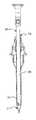
- FIGS. 1A and 1Billustrate side views of a trocar system including a cannula with associated valve housing, and an obturator with a blunt tip extending through the working channel of the cannula to facilitate placement across the abdominal wall;
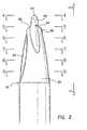
- FIG. 2is a side elevation view of the blunt tip of the obturator of the invention
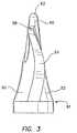
- FIG. 3is a side elevation view of the blunt tip taken along line 3 - 3 of FIG. 2 ;
- FIG. 4is an end view taken along line 4 - 4 of FIG. 2 ;
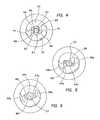
- FIG. 5is a radial cross-section view taken along line 5 - 5 of FIG. 2 ;
- FIG. 6is a radial cross-section view taken along line 6 - 6 of FIG. 2 ;
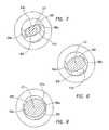
- FIG. 7is a radial cross-section view taken along line 7 - 7 of FIG. 2 ;
- FIG. 8is a radial cross-section view taken along line 8 - 8 of FIG. 2 ;
- FIG. 9is a radial cross-section view taken along line 9 - 9 of FIG. 2 ;
- FIG. 10is a schematic view illustrating each of the FIGS. 4-9 super-imposed to facilitate an understanding of the blunt tip and its twisted configuration
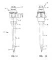
- FIG. 11illustrates a side view of a bladeless obturator of the invention having a tip formed as a blunt tapered shape
- FIG. 12illustrates a side view of a bladeless obturator of the invention having a tip formed as a pyramidal shape
- FIG. 13illustrates a side view of a bladeless obturator of the invention having a fully radiused tip
- FIGS. 14 and 15illustrate a side view and a cross-section view, respectively, of the trocar system of FIGS. 1A and 1B and further illustrating the insertion of a laparoscope;
- FIG. 16illustrates a side view of a bladeless obturator of the invention having a bulbous tip
- FIG. 17illustrates a side view of a bladeless obturator of the invention having a tip with a cutout section
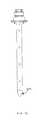
- FIG. 18illustrates a side view of a bladeless obturator of the invention having a shaft with a cutout section
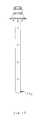
- FIG. 19illustrates a side view of a bladeless obturator of the invention and a cover for the cutout section of the shaft of FIG. 18 ;
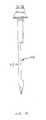
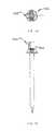
- FIGS. 20 and 21illustrate side views of a bladeless obturator of the invention having a laparoscope lock
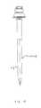
- FIGS. 22 and 23illustrate side views of a bladeless obturator of the invention including a cap with pistol-grip handle;
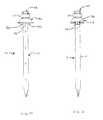
- FIGS. 24 and 25illustrate the locking mechanism between the bladeless obturator and the trocar seal of the invention
- FIGS. 26 and 27illustrate the release mechanism between the bladeless obturator and the trocar seal of the invention
- FIG. 28illustrates a top view of a laparoscope lock of the invention comprising a multiple-finger collet
- FIG. 29illustrates an optical instrument having a transparent bladeless tip of the invention
- FIGS. 30 and 31illustrate a top view and a side view, respectively, of a laparoscope lock of the invention comprising a camming member;
- FIGS. 32 and 33illustrate a top view and a side view, respectively, of a laparoscope lock of the invention comprising a clamping member
- FIGS. 34 and 35illustrate a top view and a side view, respectively, of a laparoscope lock of the invention comprising a locking collar;
- FIGS. 36 and 37illustrate a top view and a side view, respectively, of a laparoscope lock of the invention comprising a locking nut and thread.
- a trocar systemis illustrated in FIG. 1 and is designated by reference numeral 10 .
- This systemincludes a cannula 12 , defining a working channel 14 , and a valve housing 16 .
- the system 10also includes an obturator 18 having a shaft 21 extending along an axis 23 .
- a handle 25is disposed at a proximal end of the shaft 21 while a blunt tip 27 is disposed at a distal end of the shaft 21 .
- the shaft 21 of the obturator 18is sized and configured for disposition within the working channel 14 of the cannula 12 .
- the obturator 18can be placed across a body wall such as the abdominal wall to provide the cannula 12 with access across the wall and into a body cavity, such as the peritoneal or abdominal cavity.
- the blunt tip 27serves to direct the obturator 18 through the abdominal wall and the peritoneum, and can be removed with the obturator 18 once the cannula 12 is operatively disposed with the working channel 14 extending into the abdominal cavity.
- the diameter of the shaft 21can range from about 3 mm to about 20 mm and is designed to fit within a trocar seal and the cannula 12 .
- the tip 27is provided with a blunt tip configuration.
- the blunt tip 27 of the inventiontakes into account the anatomical configuration of the abdominal wall with an improved structural design and method of insertion.
- the abdominal walltypically includes a skin layer and a series of muscle layers, in addition to fat and fascia.
- the muscle layersare each defined by muscle fibers that extend generally parallel to each other in a direction that is different for each of the layers. For example, fibers of a first muscle layer and a second muscle layer may extend in directions that are generally 90 degrees off of each other.
- Such a structuremay be separated or divaricated by an obturator having a blunt tip.
- the blunt tipmay also include a twisted rectangular configuration to facilitate movement between the muscle fibers and layers. That is, the blunt tip is capable of being moved generally parallel to and between the fibers associated with a particular muscle layer.
- the fibers of the muscle layersmay be oriented at different angles to each other such that proper alignment of the tip 27 for separation of one layer may not necessarily result in proper alignment for separation of the next layer.
- the obturator 18has a blunt tip 27 to direct the obturator 18 through the different layers and a rectangular configuration that is twisted slightly so that separation of a first layer begins to rotate the distal end of the blunt tip 27 into proper orientation for separation of the next layer.
- the twisted configuration of the blunt tip 27also causes the blunt tip 27 to function, for example, with the mechanical advantage of a screw thread.
- an exemplary method of placementrequires that the user grip the handle 25 of the obturator 18 and twist it about the axis 23 .
- This twisting motion in combination with the screw configuration of the blunt tip 27converts radial movement into forward movement along the axis 23 .
- the userapplies both a forwardly directed force as well as a radial force to move the trocar system 10 in a forward direction.
- the blunt tip 27comprises generally of eight surfaces: two opposing surfaces 50 and 52 , separated by two side surfaces 54 and 56 , two end surfaces 58 and 59 , a generally tapered surface 60 formed in surfaces 50 and 52 around axis 23 and extending beyond end surfaces 58 and 59 , and a blunt surface 62 .
- the surfaces 50 and 52 , side surfaces 54 and 56 , and tapered surface 60generally define the cross-section of the blunt tip 27 from blunt surface 62 to proximal end 61 .
- This configurationcan best be appreciated with reference to the cross-section views of FIGS. 4-9 .
- the distal end of the blunt tip 27is shown with a circle 64 having the smallest circular area and a rectangle 63 having the greatest length-to-width ratio.
- the rectangle 63has a twisted, S-shaped configuration at end surfaces 58 and 59 .
- the circle 64becomes larger and the rectangle 63 becomes less twisted, and the width increases relative to the length of the rectangle 63 .
- the spiral nature of the blunt tip 27is also apparent as the circle 64 and rectangle 63 move counterclockwise around the axis 23 . This is perhaps best appreciated in a comparison of the circle 64 , the rectangle 63 and the side surfaces 54 and 56 in FIG. 6 relative to that in FIG. 5 .
- the circle 64begins to expand with increasing circular area and the rectangle 63 begins to widen with a reduction in the ratio of length to width.
- the long sides 63 ′ of the rectangle 63also tend to become more arcuate as they approach a more rounded configuration most apparent in FIGS. 8 and 9 . That is, the circle 64 and the rounded rectangle 63 become more circular with progressive proximal positions. Furthermore, the circle 64 expands at a lesser rate than the rectangle 63 , which eventually absorbs the circle 64 as shown in FIGS. 8 and 9 . In these figures, it will also be apparent that the rotation of the rectangle 63 reaches a most counterclockwise position and then begins to move clockwise. This is best illustrated in FIGS. 7-9 . This back and forth rotation results from the configuration of the side surfaces 54 and 56 , which in general are U-shaped as best illustrated in FIGS. 2 and 3 .
- the ratio of the length to width of the rectangle 63is dependent on the configuration of the side surfaces 54 and 56 , which define the short sides of the rectangle 63 as well as the configuration of the surfaces 50 and 52 , which define the long sides of the rectangle 63 .
- the side surfaces 54 and 56are most narrow at the end surfaces 58 and 59 .
- the side surfaces 54 and 56extend proximally, they reach a maximum width near the point of the most counterclockwise rotation, shown generally in FIG. 8 , and then reduce in width as they approach the proximal end 61 .
- the surfaces 50 and 52transition from a generally flat configuration at the end surfaces 58 and 59 to a generally rounded configuration at the proximal end 61 .
- the circle 64is further designated with a lower case letter a, b or c, respectively; similarly, the rectangle 63 and the side surfaces 54 and 56 are further designated with a lower case letter a, b, c, d or e, respectively, in FIGS. 5-9 .
- the circles 64 , 64 a - 64 c , the rectangles 63 , 63 a - 63 e and the side surfaces 54 , 54 a - 54 e and 56 , 56 a - 56 eare superimposed on the axis 23 to show their relative sizes, shapes and angular orientations.
- the tip 27With a generally tapered configuration at the distal end and a rectangular configuration at a distal portion of the tip, the tip 27 appears much like a flathead screwdriver having a blunt tip. More particularly, the tip 27 includes a tapered structure extending outward from the end surfaces 58 and 59 that serves to direct the obturator 18 through the tissue fibers.
- the lengths of the end surfaces 58 and 59may be aligned parallel with the fibers of each muscle layer.
- a simple back and forth twisting motion of the blunt tip 27tends to separate the fibers along natural lines of separation, opening the muscle layer to accept the larger diameter of the cannula 12 .
- the tapered and twisted configuration of the blunt tip 27directs and turns the rectangle 63 more into a parallel alignment with fibers in the next layer.
- the blunt tip 27 and the twisting or dithering motionfacilitates an easy separation of the fibers requiring a significantly reduced insertion force.
- the inventionfacilitates a unique method of separating tissue and can be applied to any object with a blunt tip and generally flat sides.
- the device of the inventioncan be operated by rotating in alternating clockwise and counterclockwise directions while applying a downward force. When rotating in alternating directions, the tissue is moved apart and a larger opening is created for a profile of greater cross-sectional area to follow. This process continues safely as the device enters the peritoneal cavity and moves to its operative position.
- the tip of the bladeless obturator 18can be formed as a generally tapered shape 27 a with a blunt distal end as illustrated in FIG. 11 , as a pyramidal shape 27 b with a blunt distal end and blunt edges as illustrated in FIG. 12 , and as a fully radiused tip 27 c for insertion through flaccid tissue or an existing body orifice such as the urethra as illustrated in FIG. 13 .
- the blunt tip 27can be formed from a translucent or a transparent material.
- the blunt tip 27can be formed from a plastic material or a glass material.
- the shaft 21 and the tip 27are formed from a transparent polycarbonate material.
- the bladeless obturator 18 of the inventionis designed to accommodate the insertion of a conventional laparoscope 30 .
- the shaft 21 of the bladeless obturator 18is hollow to allow for the insertion of the laparoscope 30 at an opening 32 .
- the shaft 21is sized and configured to allow the laparoscope 30 to slide within proximity of the tip 27 thus providing a viewing area through the tip 27 .
- An endoscopic video camera(not shown) is typically connected to the laparoscope 30 and this combination is connected to a video monitor.
- the conventional laparoscope 30By enabling the positioning of the conventional laparoscope 30 within the tip 27 of the bladeless obturator 18 , it is possible to visually observe body tissue as it is being separated by the trocar system 10 . Visualization of body tissue as it is being separated by the trocar system 10 allows a surgeon to monitor the advancement of the trocar system 10 and to avoid traumatizing vessels or organs. For example, during a laparoscopic cholecystectomy, a trocar is usually placed through the umbilicus of the patient. The placement of this trocar is typically performed in a blind fashion in that the surgeon cannot see where the tip of the trocar is as it is advanced through the abdominal wall and into the abdominal cavity of the patient.
- the tip 27may be generally hollow or it may be substantially solid to receive the distal end of the laparoscope 30 .
- the tip 27may be a solid tip.
- the tip 27may further comprise at least one portion that is marked differently from the rest of the tip to serve as an indicator, for example, of depth as the tip 27 is being inserted into the body tissue.
- the at least one portionmay be opaque or marked with a different color from the rest of the tip 27 .
- the shaft 21 and the tip 27 of the bladeless obturator 18can accommodate a laparoscope with a non-angled lens, also known as a 0° laparoscope.
- the shaft 21 and the tip 27can also accommodate a laparoscope with an angled lens such as a 30° laparoscope.
- the tip 27is designed such that when either a 0° laparoscope or a 30° laparoscope is inserted therein, the lens of the laparoscope extends beyond a distal edge 36 of the cannula 12 thereby providing a clear and unobstructed view through the tip 27 .
- the tip 27further includes a ledge 39 that properly engages either the 0° laparoscope or the 30° laparoscope.
- the bladeless obturator of the present inventionprovides a clear unobstructed view of body tissue through either a 0° or a 30° laparoscope, therefore obviating the need for a hospital to carry the additional inventory required to provide two laparoscopes for each laparoscopic surgical procedure, and obviating the need for a hospital to clean and sterilize a second laparoscope for each laparoscopic surgical procedure, and obviating the need to transfer the endoscopic video equipment from one laparoscope to the other laparoscope during each laparoscopic surgical procedure.
- the shaft 21may include a tip with a bulbous section 27 d to better accommodate the distal end of the angled lens laparoscope. By adding the bulbous section 27 d , the distal end of the angled lens laparoscope would be closer to the tip of the obturator thereby improving visualization.
- the bladeless obturatorcan include integral fiber optic light fiber elements and an integral imaging element within the shaft and the tip of the obturator.
- the bladeless obturator with integral imaging meanscan be formed of reusable or disposable materials.
- the bladeless obturator 18can be constructed as a single component or as multiple components such as the shaft 21 and the tip 27 . If the obturator 18 is constructed as a single component, then it can be formed from either disposable or reusable materials. If the obturator 18 is constructed as two or more components, then each component can be formed from either disposable or reusable materials as desired for a particular configuration. In one aspect, the obturator 18 is constructed from a single reusable material such as metal (e.g., stainless steel) or an autoclavable polymer to facilitate re-sterilization. In another aspect, the obturator 18 is formed from a transparent steam sterilizable reusable plastic material such as polyphenylsulfone or polyetherimide. The blunt tip 27 can also be coated or otherwise constructed from a soft elastomeric material. In such a case, the material can be a solid elastomer or composite elastomer/polymer.
- the shaft 21can be formed so as to be partially or fully flexible.
- the obturator 18can be inserted through a passageway containing one or more curves of virtually any shape. A partially or fully flexed obturator 18 can then be used with a flexible cannula 12 allowing greater access to an associated body cavity.
- the obturator 18can include a separately molded tip 27 and a molded or extruded shaft 21 with the two components, as explained above, comprising of the same material or different materials.
- the tip 27can then be attached to the shaft 21 by adhesive bonding, ultrasonic welding, snap-fitting, or with a shrink tube.
- the tip 27can also be overmolded over the shaft 21 to mechanically lock the two components together.
- the tip 27can be formed from a transparent material such as polycarbonate to enable visualization while the shaft 21 can be formed from either an opaque material or a transparent material.
- the shaft 21can also be formed from a metal material.
- the obturator 18can include a disposable tip that is releasably attached to a reusable shaft 21 .
- a new tip 27can be used for each procedure to provide optimal visualization through the tip 27 of the obturator 18 during each procedure.
- a shaft 18 ein accordance with another aspect of the invention including a cutout section 100 e in the tip portion 27 e that enables direct visualization of the body tissue as the tip 27 e separates tissue fibers.
- the shaft 21 ecan include a single or a plurality of cutouts 100 e in the tip 27 e or along the shaft of the obturator.
- a shaft 21 fin accordance with another aspect of the invention having a cutout portion 100 f along the axial axis of the shaft 21 f .
- the shaft 21 fhas a cross-section of about 1 ⁇ 2-circle to about 3 ⁇ 4-circle and the cutout portion 100 f has a cross-section of about 1 ⁇ 2-circle to about 1 ⁇ 4-circle.
- An advantage of this aspect of the inventionis the wall of the shaft 21 f can be a little thicker as a result of the cutout section, which makes injection molding of the shaft easier.
- a cover 102 fthat can be attached over the cutout portion 100 f of the 1 ⁇ 2-circle shaft 21 f as shown in FIG. 18 .
- a polycarbonate coveralso with a 1 ⁇ 2-circle shaped cross-section can be attached to the shaft to form a tubular cross-section.
- An advantage of molding the tubular shaft 21 f in two piecesis increased manufacturability of the shaft 21 f .
- the cover 102 fcan be attached to the shaft 21 f with an adhesive bond, an ultrasonic weld, a snap-fit, or with a shrink tube.
- the obturatorcan be formed from two clam-shell components each including one-half of the shaft and tip configuration along the axial axis of the obturator.
- the two componentscan then be affixed together using an adhesive bond, an ultrasonic weld, an outer shrink tube, or a snap fit.
- another feature of the bladeless obturator 18 of the inventionis it is designed to frictionally lock the laparoscope 30 in place using a laparoscope lock 40 , which can be formed within the handle 25 .
- the laparoscope lock 40prevents the laparoscope 30 from moving axially relative to the shaft 21 of the obturator 18 during handling within the sterile field and during insertion through a body wall but enables the laparoscope 30 to rotate freely relative to the shaft 21 .
- This rotation of the lock 40enables the trocar system 10 to be twisted during insertion into and through the abdominal wall while maintaining the laparoscope 30 in a fixed rotational position that provides for a stable viewing image on the video monitor.
- the conventional obturators with visualization propertiesinclude means for locking the laparoscope in place but these obturators lock the laparoscope both axially and rotationally.
- a drawback of the conventional devicesis the viewing image on the video monitor is unstable if the trocar is twisted during insertion. More specifically, with prior art obturator laparoscope locks, if the trocar is twisted back and forth in a clockwise and counter-clockwise fashion, the laparoscope also moves clockwise and counter-clockwise with the trocar resulting in an oscillating and disorienting viewing image on the video monitor.
- the laparoscope lock 40 of the present inventionimproves visualization and enables a more precise placement of the trocar within the body tissue and across the body wall as compared to obturators of the prior art while preventing inadvertent axial movement of the laparoscope during handling and use.
- the bladeless obturator 18further comprises a cap 42 that can be snap-fitted onto the proximal end of the obturator shaft 21 , after which the laparoscope lock 40 can be snap-fitted onto the end of the cap 42 .
- Both the cap 42 and the lock 40can be formed of a plastic material such as polycarbonate.
- the obturator cap 42can be provided with and without a pistol-grip handle. The handled version of the bladeless obturator provides a pistol-grip to ease insertion of the trocar system as illustrated in FIGS. 22 and 23 .
- the pistol-grip handleis designed to nest into the handle on the trocar seal to prevent excessive flexure of the handle during insertion of the trocar as illustrated in FIG. 23 .
- the handled bladeless obturatorincludes three components comprising of an obturator shaft 21 b , an obturator cap 42 b having a pistol-grip handle 26 b , and a laparoscope lock 40 b , all of which can be injection molded out of polycarbonate.
- the pistol-grip handle 26 bcan be formed with two components frictionally fitted together with, for example, interference pins. The interference pins can be fitted into holes in the handle 26 b to affect a frictional lock between the two components.
- the bladeless obturator 18is designed to releasably attach to a trocar seal 17 via two cantilever snap-fits 70 a , 70 b .
- the snap-fits 70 a , 70 bpassively engage the trocar seal 17 and serve to axially lock the obturator 18 to the trocar seal 17 and cannula 12 ( FIGS. 24 and 25 ).
- the bladeless obturator 18includes axial key members 74 at its proximal end which are designed to mate with axial keyways on the trocar seal 17 .
- the obturator 18As the bladeless obturator 18 is inserted into the trocar seal 17 and cannula 12 , the obturator 18 is rotated slightly to align the axial key members 74 with the axial keyways and then advanced until the snap-fits 70 a , 70 b engage the trocar seal 17 .
- the axial key members 74serve to rotationally lock the obturator 18 to the trocar seal 17 .
- the laparoscope lock 40 ccomprising a multiple-finger collet 80 c comprising a plurality of fingers 82 c .
- the multiple-finger collet 80 chas an inner diameter that is smaller than the outer diameter of the laparoscope.
- the fingers 82 c of the collet 80 cspread open during insertion of the laparoscope providing frictional engagement with the outer diameter of the laparoscope.
- the laparoscope lock 40 cis free to rotate on an obturator cap 42 c , and allows the laparoscope to freely rotate relative to the shaft of the bladeless obturator.
- the obturator shaft 21 of the bladeless obturator 18can be configured with a barb 76 at its proximal end.
- the barb 76is vertically slotted to enable the shaft 21 to flex during assembly.
- the obturator shaft 21may also include a plurality of keys (not shown) near its proximal end.
- the obturator cap 42is configured to axially slide over the barb 76 on the obturator shaft 21 to affect a one-way snap-fit lock between the two components. This snap-fit prevents the removal of the obturator cap 42 from the obturator shaft 21 .
- the obturator cap 42may further include keyways (not shown) that engage the keys on the obturator shaft 21 to rotationally index the components together.
- the obturator cap 42may further include a second barb (not shown) at its proximal end.
- the laparoscope lock 40may include a plurality of tabs (not shown) that are designed to spread and axially slide over the second barb on the obturator cap 42 to affect a one-way snap-fit lock between the obturator cap 42 and the laparoscope lock 40 . This snap-fit prevents the axial removal of the laparoscope lock 40 from the obturator cap 42 .
- the laparoscope lock 40is free to rotate relative to the obturator cap 42 .
- FIG. 29there is shown another aspect of the invention of a laparoscope 30 a having a tip 33 a configured similar to that of the tip 27 of the bladeless obturator 18 described above, the tip 33 a being adapted to snap-fit or frictionally engage the end of the laparoscope 30 a .
- the combination of the tip 33 a and the laparoscope 30 aserve to form an optical obturator having a blunt tip.
- the bladeless tip 33 acan then be removed from the laparoscope 30 a .
- the bladeless tip 33 acan be formed from either a disposable or reusable transparent material.
- the bladeless tip 33 acan be temporarily or permanently affixed to the scope 30 a by any of the known methods of attaching the two components together as explained above.
- a laparoscope lock 40 din accordance with another embodiment of the invention including an active lock comprising a camming member 43 d .
- the laparascopewould first be inserted into the shaft of the obturator and then the lock 40 d would be activated to lock the laparoscope in an axial position relative to the shaft.
- the lock 40 dcan either rotate freely to enable the laparoscope to rotate freely relative to the shaft or the lock 40 d can be rotationally fixed to prevent the laparoscope from rotating relative to the shaft.
- a lock 40 ecan include an active lock comprising a clamping member 45 e .
- the laparascopewould first be inserted into the shaft of the obturator and then the lock would be activated to lock the laparoscope in an axial position relative to the shaft.
- the lock 40 ecan either rotate freely to enable the laparoscope to rotate freely relative to the shaft or the lock 40 e can be rotationally fixed to prevent the laparoscope from rotating relative to the shaft.
- a lock 40 fin accordance with another embodiment of the invention including an active lock comprising a locking collar 46 positioned eccentrically with respect to the axis of the obturator so that as the locking collar 46 is turned, a frictional engagement with the laparoscope is affected.
- the laparoscopewould first be inserted into the locking collar 46 and the shaft of the obturator, the locking collar 46 can then be turned to frictionally engage the laparoscope.
- the laparoscope lock 40 fcan either rotate freely to enable the laparoscope to rotate freely relative to the shaft or the laparoscope lock 40 f can be rotationally fixed to prevent the laparoscope from rotating relative to the shaft.
- a laparoscope lock 40 gincluding an active lock comprising of a locking nut 48 and a thread.
- the threaded portion of the lock 40 ghas flexible elements similar to those on a collet.
- the laparoscopewould first be inserted into the threaded portion of the lock 40 g and the nut then rotated clockwise to collapse the flexible elements to frictionally engage the laparoscope. To release the laparoscope, the nut is rotated counter-clockwise.
- the laparoscope lockcan include a lock that includes an elastomeric element.
- the addition of the elastomeric elementcan enhance the frictional engagement with the laparoscope.
- An example of such an elastomeric elementis a silicone O-ring sized with an inside diameter smaller than the outside diameter of the laparoscope.
- the laparoscope lockcan either rotate freely to enable the laparoscope to rotate freely relative to the shaft or the laparoscope lock can be rotationally fixed to prevent the laparoscope from rotating relative to the shaft.
- the obturator 18can also be used as an insufflation needle having a passageway and valve to administer carbon dioxide or other insufflation gas to the peritoneal cavity.
- the obturator 18can also be used with an insufflation needle cannula in which case removal of the obturator 18 upon entry would allow for rapid insufflation of the peritoneal cavity.
- the bladeless obturatorcan be formed with a 2-3 mm outer diameter and with a small thru-hole at its distal end.
- the bladeless obturatorcan be used in conjunction with a miniaturized laparoscope to provide initial access into a hollow body cavity. Once access is obtained, the laparoscope can be removed from the bladeless obturator and an insufflation gas such as carbon dioxide can be dispensed through the obturator into the hollow body cavity.
- the bladeless obturatorcan also include holes in the tip portion to enhance the flow of insufflation gases though the obturator.
- the bladeless obturatorcan be formed with a 2-3 mm outer diameter and used in conjunction with a miniaturized laparoscope to provide initial access into a hollow body cavity. After access is obtained, the bladeless obturator can be removed from the trocar cannula and an insufflation gas such as carbon dioxide can be dispensed though the cannula and into the hollow body cavity.
- an insufflation gassuch as carbon dioxide
Landscapes
- Health & Medical Sciences (AREA)
- Surgery (AREA)
- Life Sciences & Earth Sciences (AREA)
- Medical Informatics (AREA)
- Animal Behavior & Ethology (AREA)
- Engineering & Computer Science (AREA)
- Biomedical Technology (AREA)
- Heart & Thoracic Surgery (AREA)
- Pathology (AREA)
- Molecular Biology (AREA)
- Nuclear Medicine, Radiotherapy & Molecular Imaging (AREA)
- General Health & Medical Sciences (AREA)
- Public Health (AREA)
- Veterinary Medicine (AREA)
- Oral & Maxillofacial Surgery (AREA)
- Gastroenterology & Hepatology (AREA)
- Surgical Instruments (AREA)
- Endoscopes (AREA)
Abstract
Description
Claims (13)
Priority Applications (5)
| Application Number | Priority Date | Filing Date | Title |
|---|---|---|---|
| US13/085,194US8267952B2 (en) | 2001-09-24 | 2011-04-12 | Bladeless optical obturator |
| US13/565,972US8608769B2 (en) | 2001-09-24 | 2012-08-03 | Bladeless optical obturator |
| US14/081,080US8940009B2 (en) | 2001-09-24 | 2013-11-15 | Bladeless optical obturator |
| US14/572,134US9655643B2 (en) | 2001-09-24 | 2014-12-16 | Bladeless optical obturator |
| US15/488,968US10568658B2 (en) | 2001-09-24 | 2017-04-17 | Bladeless optical obturator |
Applications Claiming Priority (6)
| Application Number | Priority Date | Filing Date | Title |
|---|---|---|---|
| US32461301P | 2001-09-24 | 2001-09-24 | |
| US10/489,403US7686823B2 (en) | 2001-09-24 | 2002-03-04 | Bladeless obturator |
| PCT/US2002/006759WO2003026512A1 (en) | 2001-09-24 | 2002-03-04 | Bladeless obturator |
| US50839003P | 2003-10-03 | 2003-10-03 | |
| US10/956,167US7947058B2 (en) | 2001-09-24 | 2004-10-01 | Bladeless optical obturator |
| US13/085,194US8267952B2 (en) | 2001-09-24 | 2011-04-12 | Bladeless optical obturator |
Related Parent Applications (1)
| Application Number | Title | Priority Date | Filing Date |
|---|---|---|---|
| US10/956,167ContinuationUS7947058B2 (en) | 2001-09-24 | 2004-10-01 | Bladeless optical obturator |
Related Child Applications (1)
| Application Number | Title | Priority Date | Filing Date |
|---|---|---|---|
| US13/565,972ContinuationUS8608769B2 (en) | 2001-09-24 | 2012-08-03 | Bladeless optical obturator |
Publications (2)
| Publication Number | Publication Date |
|---|---|
| US20110190592A1 US20110190592A1 (en) | 2011-08-04 |
| US8267952B2true US8267952B2 (en) | 2012-09-18 |
Family
ID=34421732
Family Applications (6)
| Application Number | Title | Priority Date | Filing Date |
|---|---|---|---|
| US10/956,167Active2027-01-11US7947058B2 (en) | 2001-09-24 | 2004-10-01 | Bladeless optical obturator |
| US13/085,194Expired - LifetimeUS8267952B2 (en) | 2001-09-24 | 2011-04-12 | Bladeless optical obturator |
| US13/565,972Expired - LifetimeUS8608769B2 (en) | 2001-09-24 | 2012-08-03 | Bladeless optical obturator |
| US14/081,080Expired - LifetimeUS8940009B2 (en) | 2001-09-24 | 2013-11-15 | Bladeless optical obturator |
| US14/572,134Expired - Fee RelatedUS9655643B2 (en) | 2001-09-24 | 2014-12-16 | Bladeless optical obturator |
| US15/488,968Expired - LifetimeUS10568658B2 (en) | 2001-09-24 | 2017-04-17 | Bladeless optical obturator |
Family Applications Before (1)
| Application Number | Title | Priority Date | Filing Date |
|---|---|---|---|
| US10/956,167Active2027-01-11US7947058B2 (en) | 2001-09-24 | 2004-10-01 | Bladeless optical obturator |
Family Applications After (4)
| Application Number | Title | Priority Date | Filing Date |
|---|---|---|---|
| US13/565,972Expired - LifetimeUS8608769B2 (en) | 2001-09-24 | 2012-08-03 | Bladeless optical obturator |
| US14/081,080Expired - LifetimeUS8940009B2 (en) | 2001-09-24 | 2013-11-15 | Bladeless optical obturator |
| US14/572,134Expired - Fee RelatedUS9655643B2 (en) | 2001-09-24 | 2014-12-16 | Bladeless optical obturator |
| US15/488,968Expired - LifetimeUS10568658B2 (en) | 2001-09-24 | 2017-04-17 | Bladeless optical obturator |
Country Status (6)
| Country | Link |
|---|---|
| US (6) | US7947058B2 (en) |
| EP (9) | EP2545862B1 (en) |
| JP (1) | JP2007516737A (en) |
| AU (4) | AU2004277429B2 (en) |
| CA (1) | CA2540682A1 (en) |
| WO (1) | WO2005032348A2 (en) |
Cited By (18)
| Publication number | Priority date | Publication date | Assignee | Title |
|---|---|---|---|---|
| US8608769B2 (en) | 2001-09-24 | 2013-12-17 | Applied Medical Resources Corporation | Bladeless optical obturator |
| US9254125B2 (en) | 2001-09-24 | 2016-02-09 | Applied Medical Resources Corporation | Bladeless obturator |
| US9314266B2 (en) | 2008-09-29 | 2016-04-19 | Applied Medical Resources Corporation | First-entry trocar system |
| US9492062B2 (en) | 2006-10-06 | 2016-11-15 | Applied Medical Resources Corporation | Visual insufflation port |
| US9545248B2 (en) | 2002-05-16 | 2017-01-17 | Applied Medical Resources Corporation | Blunt tip obturator |
| US9693802B2 (en) | 2012-06-06 | 2017-07-04 | Covidien Lp | Obturator tip with insufflation pathway |
| US10022149B2 (en) | 2012-09-28 | 2018-07-17 | Covidien Lp | Optical trocar visualization system and apparatus |
| US10226589B2 (en) | 2003-10-03 | 2019-03-12 | Applied Medical Resources Corporation | Insufflating optical surgical instrument |
| US11051851B2 (en) | 2017-08-04 | 2021-07-06 | The Brigham And Women's Hospital, Inc. | Veress-type needles with illuminated guidance and safety features |
| US11357542B2 (en) | 2019-06-21 | 2022-06-14 | Covidien Lp | Valve assembly and retainer for surgical access assembly |
| USD956219S1 (en) | 2020-07-10 | 2022-06-28 | Covidien Lp | Port apparatus |
| US11382662B2 (en) | 2017-08-04 | 2022-07-12 | The Brigham And Women's Hospital, Inc. | Trocars and veress-type needles with illuminated guidance and safety features |
| USD963851S1 (en) | 2020-07-10 | 2022-09-13 | Covidien Lp | Port apparatus |
| US11446058B2 (en) | 2020-03-27 | 2022-09-20 | Covidien Lp | Fixture device for folding a seal member |
| US11541218B2 (en) | 2020-03-20 | 2023-01-03 | Covidien Lp | Seal assembly for a surgical access assembly and method of manufacturing the same |
| US11642153B2 (en) | 2020-03-19 | 2023-05-09 | Covidien Lp | Instrument seal for surgical access assembly |
| US11717321B2 (en) | 2020-04-24 | 2023-08-08 | Covidien Lp | Access assembly with retention mechanism |
| US11812991B2 (en) | 2019-10-18 | 2023-11-14 | Covidien Lp | Seal assemblies for surgical access assemblies |
Families Citing this family (137)
| Publication number | Priority date | Publication date | Assignee | Title |
|---|---|---|---|---|
| DE69937466T2 (en)* | 1998-12-01 | 2008-11-13 | Atropos Ltd., Bray | Laparoscopic sealed access device |
| US7559893B2 (en) | 1998-12-01 | 2009-07-14 | Atropos Limited | Wound retractor device |
| US7998068B2 (en) | 1998-12-01 | 2011-08-16 | Atropos Limited | Instrument access device |
| US6254534B1 (en) | 1999-10-14 | 2001-07-03 | Atropos Limited | Retractor |
| US20050192483A1 (en)* | 1998-12-01 | 2005-09-01 | Frank Bonadio | Device |
| US7537564B2 (en) | 1998-12-01 | 2009-05-26 | Atropos Limited | Wound retractor device |
| CN100512766C (en)* | 1998-12-01 | 2009-07-15 | 阿特波斯有限公司 | A surgical device for retracting and/or sealing an incision |
| US7540839B2 (en)* | 1999-10-14 | 2009-06-02 | Atropos Limited | Wound retractor |
| AU2002224519A1 (en)* | 2000-07-21 | 2002-02-05 | Atropos Limited | A surgical instrument |
| JP5190169B2 (en) | 2000-10-19 | 2013-04-24 | アプライド メディカル リソーシーズ コーポレイション | Surgical access instruments and methods |
| EP2422829B1 (en) | 2001-08-14 | 2013-03-06 | Applied Medical Resources Corporation | Surgical access sealing apparatus |
| US6958037B2 (en) | 2001-10-20 | 2005-10-25 | Applied Medical Resources Corporation | Wound retraction apparatus and method |
| EP2343032B1 (en) | 2002-06-05 | 2012-05-09 | Applied Medical Resources Corporation | Wound retractor |
| US9271753B2 (en) | 2002-08-08 | 2016-03-01 | Atropos Limited | Surgical device |
| DE60314464T2 (en)* | 2002-09-19 | 2008-02-14 | Atropos Ltd., Bray | SURGICAL WOUND RETRACTOR |
| DE60315188T2 (en)* | 2002-12-16 | 2008-04-03 | Atropos Ltd., Bray | SURGICAL DEVICE |
| US20050020884A1 (en) | 2003-02-25 | 2005-01-27 | Hart Charles C. | Surgical access system |
| CA2533204A1 (en) | 2003-08-06 | 2005-02-17 | Applied Medical Resources Corporation | Surgical device with tack-free gel and method of manufacture |
| US7163510B2 (en) | 2003-09-17 | 2007-01-16 | Applied Medical Resources Corporation | Surgical instrument access device |
| WO2005034766A2 (en)* | 2003-10-15 | 2005-04-21 | Atropos Limited | A surgical sealing device |
| US20060161050A1 (en)* | 2003-10-15 | 2006-07-20 | John Butler | A surgical sealing device |
| US7297141B2 (en)* | 2004-01-20 | 2007-11-20 | Ethicon Endo-Surgery, Inc. | Method for accessing an operative space |
| US8007477B2 (en) | 2004-03-22 | 2011-08-30 | Applied Medical Resources Corporation | Surgical access port and method of using same |
| US9638770B2 (en)* | 2004-05-21 | 2017-05-02 | Devicor Medical Products, Inc. | MRI biopsy apparatus incorporating an imageable penetrating portion |
| US9770261B2 (en)* | 2004-10-28 | 2017-09-26 | Nico Corporation | Surgical access assembly and method of using same |
| US9161820B2 (en) | 2004-10-28 | 2015-10-20 | Nico Corporation | Surgical access assembly and method of using same |
| US9186175B2 (en) | 2004-10-28 | 2015-11-17 | Nico Corporation | Surgical access assembly and method of using same |
| US9216015B2 (en) | 2004-10-28 | 2015-12-22 | Vycor Medical, Inc. | Apparatus and methods for performing brain surgery |
| US7824327B2 (en) | 2005-04-12 | 2010-11-02 | Tyco Healthcare Group Llp | Optical trocar with scope holding assembly |
| US20060287583A1 (en) | 2005-06-17 | 2006-12-21 | Pool Cover Corporation | Surgical access instruments for use with delicate tissues |
| JP2009501045A (en) | 2005-07-15 | 2009-01-15 | アトロポス・リミテッド | Wound retractor |
| US7794644B2 (en)* | 2005-10-05 | 2010-09-14 | Applied Medical Resources Corporation | Thin-walled optical obturator |
| AU2006304141B2 (en) | 2005-10-14 | 2012-07-05 | Applied Medical Resources Corporation | Gel cap for wound retractor |
| EP1933733A2 (en) | 2005-10-14 | 2008-06-25 | Applied Medical Resources Corporation | Surgical access port |
| DE102006015690A1 (en)* | 2006-03-27 | 2007-10-11 | Aesculap Ag & Co. Kg | Surgical sealing element, surgical seal and surgical sealing system |
| AU2013203912B2 (en)* | 2006-10-06 | 2014-09-25 | Applied Medical Resources Corporation | Visual insufflation obturator |
| AU2016259433B2 (en)* | 2006-10-06 | 2018-05-17 | Applied Medical Resources Corporation | Visual Insufflation Obturator |
| ES2279733B1 (en)* | 2006-11-27 | 2008-08-16 | Rudolf Morgenstern Lopez | DEVICE FOR ELIMINATION OF FABRIC IN ENDOSCOPIC OPERATIONS. |
| KR100828135B1 (en)* | 2006-12-13 | 2008-05-08 | 이은규 | Biotissue exfoliator for endoscope |
| AU2007334420B2 (en)* | 2006-12-15 | 2013-03-14 | Covidien Lp | Trocar assembly with obturator design |
| EP2101658A4 (en)* | 2006-12-20 | 2013-07-03 | Covidien Lp | Surgical visual obturator |
| AU2008219028B2 (en) | 2007-02-21 | 2014-02-13 | Covidien Lp | Obturator tips |
| EP2120675A4 (en)* | 2007-02-28 | 2013-03-27 | Covidien Lp | Surgical optical access apparatus |
| AU2008239409B2 (en)* | 2007-04-11 | 2013-09-19 | Covidien Lp | Visualized entry trocar with moving blade |
| US8202290B2 (en)* | 2007-04-17 | 2012-06-19 | Tyco Healthcare Group Lp | Visual obturator with handle |
| AU2008243046B2 (en)* | 2007-04-18 | 2013-06-06 | Covidien Lp | Trocar assembly with obturator dissector |
| EP2146644A4 (en) | 2007-05-11 | 2012-07-18 | Applied Med Resources | Surgical retractor |
| WO2008141291A1 (en) | 2007-05-11 | 2008-11-20 | Applied Medical Resources Corporation | Surgical retractor with gel pad |
| US8657740B2 (en) | 2007-06-05 | 2014-02-25 | Atropos Limited | Instrument access device |
| WO2008149332A1 (en) | 2007-06-05 | 2008-12-11 | Atropos Limited | An instrument access device |
| US8192353B2 (en)* | 2007-10-05 | 2012-06-05 | Tyco Healthcare Group Lp | Visual obturator |
| AU2008229774B2 (en)* | 2007-10-05 | 2013-05-16 | Covidien Lp | Two-mode bladeless trocar assembly |
| US8282663B2 (en) | 2007-10-05 | 2012-10-09 | Tyco Healthcare Group Lp | Bladeless obturator for use in a surgical trocar assembly |
| US8262673B2 (en)* | 2007-10-19 | 2012-09-11 | Daniel Larkin | Amniotomy device and assembly |
| US8257364B2 (en)* | 2007-10-19 | 2012-09-04 | Daniel Larkin | Amniotomy device and assembly |
| CA2711116C (en) | 2008-01-22 | 2017-08-29 | Applied Medical Resources Corporation | Surgical instrument access device |
| EP2851020B1 (en)* | 2008-01-25 | 2016-01-20 | Applied Medical Resources Corporation | Insufflating access system |
| JP5153892B2 (en)* | 2008-02-07 | 2013-02-27 | カーディアック ペースメイカーズ, インコーポレイテッド | Wireless tissue electrical stimulation |
| DE102008033374A1 (en) | 2008-07-09 | 2010-01-14 | Aesculap Ag | Surgical protection device for a surgical sealing element and surgical sealing system |
| DE102008033375A1 (en) | 2008-07-09 | 2010-01-14 | Aesculap Ag | Surgical sealing element holder for holding a surgical sealing element and surgical sealing system |
| CN102112163A (en)* | 2008-07-28 | 2011-06-29 | 脊柱诊察公司 | Penetrating member with direct visualization |
| AU2015201956B2 (en)* | 2008-09-29 | 2017-04-13 | Applied Medical Resources Corporation | First-entry trocar system |
| CA2739910C (en) | 2008-10-13 | 2017-06-06 | Applied Medical Resources Corporation | Single port access system |
| US8375955B2 (en) | 2009-02-06 | 2013-02-19 | Atropos Limited | Surgical procedure |
| US10849644B2 (en) | 2009-03-09 | 2020-12-01 | A.M. Surgical, Inc. | Surgical device |
| WO2011033495A1 (en) | 2009-09-17 | 2011-03-24 | Atropos Limited | An instrument access device |
| US20110082338A1 (en)* | 2009-10-01 | 2011-04-07 | Tyco Healthcare Group Lp | Port fixation with varying thread pitch |
| US8979883B2 (en) | 2009-12-17 | 2015-03-17 | Covidien Lp | Obturator tip |
| US9226774B2 (en)* | 2009-12-17 | 2016-01-05 | Covidien Lp | Visual obturator with tip openings |
| WO2011087462A1 (en)* | 2010-01-14 | 2011-07-21 | Sunton Wongsiri | The surgical visual field enhancer apparatus and its method of use |
| US20110196206A1 (en)* | 2010-02-05 | 2011-08-11 | Tyco Healthcare Group Lp | Port fixation with varying thread diameter |
| US20110196205A1 (en)* | 2010-02-05 | 2011-08-11 | Tyco Healthcare Group Lp | Surgical portal locking system |
| US9386915B2 (en)* | 2010-07-30 | 2016-07-12 | Nilesh R. Vasan | Disposable, self-contained laryngoscope and method of using same |
| US9289114B2 (en) | 2010-07-30 | 2016-03-22 | Nilesh R. Vasan | Disposable, self-contained laryngoscope and method of using same |
| US8961552B2 (en) | 2010-09-21 | 2015-02-24 | Covidien Lp | Bladeless obturators and bladeless obturator members |
| USD655005S1 (en)* | 2010-09-21 | 2012-02-28 | Tyco Healthcare Group Lp | Bladeless obturator member |
| USD656233S1 (en) | 2010-09-21 | 2012-03-20 | Tyco Healthcare Group Lp | Bladeless obturator member |
| USD654168S1 (en)* | 2010-09-21 | 2012-02-14 | Tyco Healthcare Group Lp | Bladeless obturator member |
| JP6396657B2 (en) | 2010-10-01 | 2018-09-26 | アプライド メディカル リソーシーズ コーポレイション | Natural orifice surgery system |
| US9289115B2 (en) | 2010-10-01 | 2016-03-22 | Applied Medical Resources Corporation | Natural orifice surgery system |
| US8821526B2 (en) | 2010-11-11 | 2014-09-02 | Specialtycare, Inc. | Trocar |
| US9101315B2 (en) | 2010-11-11 | 2015-08-11 | Specialty Care, Inc. | Cannula system |
| KR20140018324A (en) | 2011-05-02 | 2014-02-12 | 어플라이드 메디컬 리소시스 코포레이션 | Low-profile surgical universal access port |
| US8758236B2 (en) | 2011-05-10 | 2014-06-24 | Applied Medical Resources Corporation | Wound retractor |
| GB2492987A (en) | 2011-07-19 | 2013-01-23 | Surgical Innovations Ltd | Optical trocar assembly |
| ES2769810T3 (en)* | 2011-10-18 | 2020-06-29 | Covidien Lp | Optical trocar system |
| CN102499737B (en)* | 2011-11-01 | 2014-06-18 | 东莞麦可龙医疗科技有限公司 | Manufacturing method of visual puncture outfit for disposable laparoscope and puncture outfit implementing same |
| US9186173B2 (en) | 2012-04-27 | 2015-11-17 | Specialty Care, Inc. | Optical obturator system |
| US20130338694A1 (en)* | 2012-06-18 | 2013-12-19 | Covidien Lp | Optical obturator assembly |
| US9402532B2 (en) | 2012-06-26 | 2016-08-02 | Covidien Lp | Optical obturator |
| CA2894544A1 (en) | 2012-12-27 | 2014-07-03 | Covidien Lp | Two-shot molded optical obturator |
| US20140235946A1 (en)* | 2013-02-21 | 2014-08-21 | Covidien Lp | Optical obturator visualization system |
| US9271752B2 (en)* | 2013-03-13 | 2016-03-01 | Swan Valley Medical Incorporated | Method and apparatus for placing a cannula in a bladder |
| US9308020B2 (en) | 2013-03-14 | 2016-04-12 | Cook Medical Technologies Llc | Tri-fluted vascular access needle |
| BR112015022987A2 (en)* | 2013-03-15 | 2017-07-18 | Olive Medical Corp | integrated prism trocar visualization for use with angled endoscope |
| JP2016512725A (en) | 2013-03-15 | 2016-05-09 | アプライド メディカル リソーシーズ コーポレイション | Mechanical gel surgical access instrument |
| US10198966B2 (en)* | 2013-07-24 | 2019-02-05 | Applied Medical Resources Corporation | Advanced first entry model for surgical simulation |
| DE112014004020B4 (en) | 2013-09-03 | 2023-12-14 | Fujifilm Corporation | Endoscopic surgical device and overtube |
| WO2015033909A1 (en) | 2013-09-03 | 2015-03-12 | 富士フイルム株式会社 | Endoscopic surgical device and outer sleeve |
| DE112014004014B4 (en) | 2013-09-03 | 2023-12-14 | Fujifilm Corporation | Endoscopic surgical device and overtube |
| JP6068654B2 (en) | 2013-09-03 | 2017-01-25 | 富士フイルム株式会社 | Endoscopic surgical apparatus and mantle tube |
| USD743549S1 (en)* | 2013-10-27 | 2015-11-17 | MIS Implants Technologies Ltd. | Dental drill |
| EP3142541A4 (en) | 2014-05-13 | 2017-04-26 | Vycor Medical, Inc. | Guidance system mounts for surgical introducers |
| EP3169510B1 (en) | 2014-07-18 | 2018-10-03 | Applied Medical Resources Corporation | Method for manufacturing gels having permanent tack free coatings |
| KR20240172766A (en) | 2014-08-15 | 2024-12-10 | 어플라이드 메디컬 리소시스 코포레이션 | Natural orifice surgery system |
| WO2016085930A2 (en) | 2014-11-25 | 2016-06-02 | Applied Medical Resources Corporation | Circumferential wound retraction with support and guidance structures |
| US10368908B2 (en) | 2015-09-15 | 2019-08-06 | Applied Medical Resources Corporation | Surgical robotic access system |
| WO2017062850A2 (en) | 2015-10-07 | 2017-04-13 | Applied Medical Resources Corporation | Wound retractor with multi-segment outer ring |
| US10327809B2 (en) | 2016-02-29 | 2019-06-25 | Covidien Lp | Clip collar advanced fixation |
| CN105935308B (en)* | 2016-06-27 | 2019-02-05 | 江苏风和医疗器材股份有限公司 | Puncture core tip and puncture core and puncture outfit with it |
| CN105935309A (en)* | 2016-06-27 | 2016-09-14 | 江苏风和医疗器材有限公司 | Puncture core tip, puncture core with the same and puncture device |
| CN105935307B (en)* | 2016-06-27 | 2021-08-06 | 江苏风和医疗器材股份有限公司 | Puncture core tip and puncture core and puncture device with same |
| KR101712611B1 (en)* | 2016-08-05 | 2017-03-06 | 김기성 | Laparoscopic port site opening and closing apparatus |
| KR102486092B1 (en) | 2016-08-17 | 2023-01-06 | 리바운드 세라퓨틱스 코포레이션 | Cannula with Proximally Mounted Camera |
| AU2017324450B2 (en) | 2016-09-12 | 2022-09-29 | Applied Medical Resources Corporation | Surgical robotic access system for irregularly shaped robotic actuators and associated robotic surgical instruments |
| WO2018080487A1 (en)* | 2016-10-26 | 2018-05-03 | A.M. Surgical, Inc. | Surgical device |
| US12178469B2 (en) | 2016-11-07 | 2024-12-31 | Vycor Medical Inc. | Surgical introducer with guidance system receptacle |
| US10543016B2 (en) | 2016-11-07 | 2020-01-28 | Vycor Medical, Inc. | Surgical introducer with guidance system receptacle |
| US10376258B2 (en) | 2016-11-07 | 2019-08-13 | Vycor Medical, Inc. | Surgical introducer with guidance system receptacle |
| CN106510809B (en)* | 2016-12-09 | 2023-05-26 | 成都五义医疗科技有限公司 | Improved knife-free visual puncture needle |
| US11103126B2 (en) | 2017-05-03 | 2021-08-31 | Lsi Solutions, Inc. | Surgical equipment holder |
| US11864958B2 (en) | 2017-05-03 | 2024-01-09 | Lsi Solutions, Inc. | Surgical equipment holder |
| US12102295B2 (en)* | 2017-09-18 | 2024-10-01 | Periwinkle Technologies Pvt. Ltd. | Digital device facilitating body cavity screening and diagnosis |
| US10722111B2 (en) | 2018-03-13 | 2020-07-28 | Covidien Lp | Optical trocar assembly |
| USD876625S1 (en) | 2018-08-07 | 2020-02-25 | Adroit Surgical, Llc | Laryngoscope |
| JP2022508311A (en)* | 2018-08-09 | 2022-01-19 | オプティカル スパイン | Translucent illuminated endoscope probe |
| US10736659B2 (en) | 2018-10-23 | 2020-08-11 | Covidien Lp | Optical trocar assembly |
| CN109907800A (en)* | 2019-01-08 | 2019-06-21 | 罗和古 | A kind of visualization microtrauma puncture diagnosing and treating apparatus |
| CA3130085A1 (en) | 2019-02-22 | 2020-08-27 | Rebound Therapeutics Corporation | Cannula and obturator with a transparent tip with an opaque component |
| US11491006B2 (en) | 2019-04-10 | 2022-11-08 | Neovasc Tiara Inc. | Prosthetic valve with natural blood flow |
| CA3142277A1 (en)* | 2019-05-31 | 2020-12-03 | Nico Corporation | Adapter for a surgical access device |
| US11439429B2 (en) | 2019-07-11 | 2022-09-13 | New View Surgical | Cannula assembly with deployable camera |
| US11957522B2 (en) | 2019-08-05 | 2024-04-16 | Lsi Solutions, Inc. | Dock for surgical equipment holder |
| WO2021080944A1 (en) | 2019-10-21 | 2021-04-29 | New View Surgical Inc. | Thermal control of imaging system |
| WO2021161228A1 (en)* | 2020-02-14 | 2021-08-19 | Fisher & Paykel Healthcare Limited | Obturator for cannula with internal features |
| EP4243722A4 (en) | 2020-11-11 | 2024-11-13 | New View Surgical, Inc. | MULTI-CAMERA IMAGING SYSTEM |
| WO2024191719A1 (en)* | 2023-03-10 | 2024-09-19 | New View Surgical | Cannula assembly for enhancing critical anatomy visualization during a surgical procedure |
Citations (94)
| Publication number | Priority date | Publication date | Assignee | Title |
|---|---|---|---|---|
| US207932A (en) | 1878-09-10 | Improvement in surgical dilators | ||
| US1147408A (en) | 1915-02-08 | 1915-07-20 | Charles Edmund Kells | Trocar. |
| DE365049C (en) | 1922-12-07 | Albrecht Meyenberg Dr | Tube speculum for women | |
| US1727495A (en) | 1929-09-10 | Beinhold h | ||
| US2102274A (en) | 1934-06-29 | 1937-12-14 | Louise D Larimore | Microscope for pathological research |
| US2699770A (en) | 1951-05-11 | 1955-01-18 | Centre Nat Rech Scient | Endoscope |
| US2932294A (en) | 1954-10-13 | 1960-04-12 | Centre Nat Rech Scient | Lighting devices for endoscopes |
| US3021834A (en) | 1954-03-11 | 1962-02-20 | Sheldon Edward Emanuel | Endoscopes |
| US3042022A (en) | 1959-05-25 | 1962-07-03 | Bausch & Lomb | Illumination means for diagnostic instrument |
| FR1370580A (en) | 1962-12-04 | 1964-08-28 | Centre Nat Rech Scient | Contact endoscope |
| US3224320A (en) | 1959-05-05 | 1965-12-21 | Slagteriernes Forskningsinst | Apparatus for determination of the distribution of meat and fat in slaughtered animals or parts thereof |
| US3417745A (en) | 1963-08-23 | 1968-12-24 | Sheldon Edward Emanuel | Fiber endoscope provided with focusing means and electroluminescent means |
| US3437747A (en) | 1964-03-24 | 1969-04-08 | Sheldon Edward E | Devices for inspection using fiberoptic members |
| US3459189A (en) | 1965-07-28 | 1969-08-05 | Brunswick Corp | Trocar catheter |
| US3556085A (en) | 1968-02-26 | 1971-01-19 | Olympus Optical Co | Optical viewing instrument |
| DE1616107B1 (en) | 1968-02-26 | 1971-04-08 | Olympus Optical Co | Microscope for introducing and observing body cavities and an optical instrument with such a microscope |
| US3613684A (en) | 1969-09-19 | 1971-10-19 | David S Sheridan | Trocar catheters |
| US3653338A (en) | 1970-09-17 | 1972-04-04 | Flambeau Plastics Corp | Hollow polyethylene rolling pin |
| DE2218901A1 (en) | 1972-04-19 | 1973-10-31 | Storz Karl Fa | TROCAR FOR INSERTING SURGICAL INSTRUMENTS INTO BODY CAVES |
| US3821956A (en) | 1973-08-14 | 1974-07-02 | D Gordhamer | Bovine teat dilator and medicament dispenser |
| US3870036A (en) | 1972-05-01 | 1975-03-11 | Bio Analytical Labor Inc | Improved speculum barrel member |
| US3961621A (en) | 1974-02-06 | 1976-06-08 | Akademiet For De Tekniske Videnskaber, Svejsecentralen | Surgical tool for taking biological samples |
| US3994287A (en) | 1974-07-01 | 1976-11-30 | Centre De Recherche Industrielle Du Quebec | Trocar |
| DE2538758A1 (en) | 1975-08-30 | 1977-03-10 | Eberhard Dr Med Regenbogen | Rectoscope obturator with transparent bolt - is coupled to annular end piece over thin parallel connecting rods |
| US4028987A (en) | 1973-07-18 | 1977-06-14 | Illinois Tool Works Inc. | Self-drilling screws |
| US4112932A (en) | 1977-02-24 | 1978-09-12 | Chiulli Robert D | Laparoscopic cannula |
| DE2929233A1 (en) | 1978-07-19 | 1980-01-31 | Medtronic Inc | DEVICE FOR FORMING A TISSUE TUNNEL AND / OR FOR POSITIONING A PIPE IN BODY TISSUE |
| US4191191A (en) | 1978-02-13 | 1980-03-04 | Auburn Robert M | Laproscopic trocar |
| US4222375A (en) | 1978-03-10 | 1980-09-16 | Miguel Martinez | In vivo illumination system utilizing a cannula with a conical opening allowing a snap-fit with a conical lens and an aperture for flow of fluids and utilizing a housing with a spherical lens for focusing light onto fiber optics |
| DE2922239A1 (en) | 1979-05-31 | 1980-12-04 | Olympus Optical Co | Vaccination needle penetration sensor - uses reflected light passing through optical fibres to phototransistor to produce visual or audible indication w.r.t. penetration depth |
| US4248214A (en) | 1979-05-22 | 1981-02-03 | Robert S. Kish | Illuminated urethral catheter |
| US4254762A (en) | 1979-10-23 | 1981-03-10 | Inbae Yoon | Safety endoscope system |
| US4269192A (en) | 1977-12-02 | 1981-05-26 | Olympus Optical Co., Ltd. | Stabbing apparatus for diagnosis of living body |
| US4285618A (en) | 1979-10-12 | 1981-08-25 | Shanley Stephen E Jr | Rotary milling cutter |
| US4299230A (en) | 1979-05-09 | 1981-11-10 | Olympus Optical Co., Ltd. | Stabbing apparatus for diagnosis of living body |
| US4311138A (en) | 1980-03-10 | 1982-01-19 | Sugarman Edward D | Illuminated hypodermic needle |
| US4319563A (en) | 1977-12-02 | 1982-03-16 | Olympus Optical Co., Ltd. | Endoscope with a smoothly curved distal end face |
| SU942730A1 (en) | 1980-07-11 | 1982-07-15 | Московский научно-исследовательский институт туберкулеза | Trochar |
| US4356826A (en) | 1979-05-09 | 1982-11-02 | Olympus Optical Co., Ltd. | Stabbing apparatus for diagnosis of living body |
| US4498902A (en) | 1982-11-13 | 1985-02-12 | Purdue Research Foundation | Catheter guide |
| EP0135364A2 (en) | 1983-08-24 | 1985-03-27 | Endotherapeutics Corporation | Trocar assembly |
| US4535773A (en) | 1982-03-26 | 1985-08-20 | Inbae Yoon | Safety puncturing instrument and method |
| US4537593A (en) | 1983-06-06 | 1985-08-27 | Becton, Dickinson And Co. | Self-venting, non-coring needle assembly |
| US4567882A (en) | 1982-12-06 | 1986-02-04 | Vanderbilt University | Method for locating the illuminated tip of an endotracheal tube |
| SU1328658A1 (en) | 1986-02-04 | 1987-08-07 | Ленинградское Отделение Всесоюзного Государственного Научно-Исследовательского И Проектно-Изыскательского Института "Атомтеплоэлектропроект" | Centrifugal nozzle |
| SU1329769A1 (en) | 1985-02-13 | 1987-08-15 | Львовский государственный медицинский институт | Rectoscope |
| EP0312787A1 (en) | 1987-10-21 | 1989-04-26 | Richard Wolf GmbH | Endoscopic instrument set |
| EP0347140A1 (en) | 1988-06-13 | 1989-12-20 | MacAnally, Richard B. | Dual view endoscope |
| US4895431A (en) | 1986-11-13 | 1990-01-23 | Olympus Optical Co., Ltd. | Method of processing endoscopic images |
| US4901142A (en) | 1987-03-23 | 1990-02-13 | Olympus Optical Co., Ltd. | Video scope system |
| EP0369937A1 (en) | 1988-11-18 | 1990-05-23 | Effner Biomet GmbH | Endoscope, in particular an arthroscope |
| EP0369936A1 (en) | 1988-11-18 | 1990-05-23 | Effner Biomet GmbH | Endoscope |
| US4959067A (en) | 1983-11-21 | 1990-09-25 | Joseph J. Berke | Manual surgical separator structure and method |
| US4972827A (en) | 1989-02-06 | 1990-11-27 | Fuji Photo Optical Co., Ltd. | Guide device for percutaneous insertion of endoscope |
| DE4020956A1 (en) | 1989-06-30 | 1991-01-10 | Jaraiz Ricardo Fernandez Blanc | Needle for puncturing spinal column - has tubular body with sliding insert and both parts having conical tips |
| US5057082A (en) | 1988-11-04 | 1991-10-15 | Plastic Injectors, Inc. | Trocar assembly |
| US5066288A (en) | 1988-07-06 | 1991-11-19 | Ethicon, Inc. | Safety trocar |
| US5098388A (en) | 1991-05-02 | 1992-03-24 | Richard Kulkashi | Veress needle assembly |
| US5104388A (en) | 1990-05-08 | 1992-04-14 | Fbk International Corporation | Membrane splittable tubing |
| DE4133073A1 (en) | 1990-10-11 | 1992-04-16 | Effner Gmbh | Trocar for producing access for surgery under endoscopic control - has pointed tip at one end of shaft and optical system with objective in vicinity to tip |
| DE4035146A1 (en) | 1990-11-06 | 1992-05-07 | Riek Siegfried | INSTRUMENT FOR PENETRATING BODY TISSUE |
| US5147376A (en) | 1990-05-04 | 1992-09-15 | Francesco Pianetti | Trocar needle laparoscopy with a threaded truncated cone bit |
| US5159920A (en) | 1990-06-18 | 1992-11-03 | Mentor Corporation | Scope and stent system |
| US5163941A (en) | 1991-05-07 | 1992-11-17 | California Medical Products | Intubation device |
| DE4116648A1 (en) | 1991-05-22 | 1992-11-26 | Helmut Dipl Ing Wurster | Self-cutting trocar insertable in sleeve for penetrating abdominal wall - has manual or motor driven cutting tool so hat power which is normally not used for inserting trocar is considerably reduced and insertion can be controlled |
| US5217441A (en) | 1989-08-15 | 1993-06-08 | United States Surgical Corporation | Trocar guide tube positioning device |
| US5246425A (en) | 1992-09-21 | 1993-09-21 | Daniel Hunsberger | Trocar and cannula assembly |
| US5250068A (en) | 1990-11-30 | 1993-10-05 | Yakuouji Shinkiyu Chiryouin | Optical transmission type acupuncture needle |
| US5256149A (en) | 1992-02-14 | 1993-10-26 | Ethicon, Inc. | Trocar having transparent cannula and method of using |
| US5269316A (en) | 1991-08-16 | 1993-12-14 | Spitalny Hans Henning | Surgical instrument |
| US5279567A (en) | 1992-07-02 | 1994-01-18 | Conmed Corporation | Trocar and tube with pressure signal |
| US5290276A (en) | 1992-02-06 | 1994-03-01 | Sewell Jr Frank | Rotatable laparoscopic puncturing instrument |
| US5441041A (en) | 1993-09-13 | 1995-08-15 | United States Surgical Corporation | Optical trocar |
| US5540711A (en)* | 1992-06-02 | 1996-07-30 | General Surgical Innovations, Inc. | Apparatus and method for developing an anatomic space for laparoscopic procedures with laparoscopic visualization |
| US5562695A (en) | 1995-01-10 | 1996-10-08 | Obenchain; Theodore G. | Nerve deflecting conduit needle and method |
| US5569292A (en) | 1995-02-01 | 1996-10-29 | Ethicon Endo-Surgery, Inc. | Surgical penetration instrument with transparent blades and tip cover |
| US5591192A (en) | 1995-02-01 | 1997-01-07 | Ethicon Endo-Surgery, Inc. | Surgical penetration instrument including an imaging element |
| US5662673A (en) | 1995-04-05 | 1997-09-02 | Kieturakis; Maciej J. | Surgical trocar and method for placing a trocar sleeve in a body wall |
| US5676611A (en) | 1996-11-18 | 1997-10-14 | Elliot A. Rudell | Foraminous shell foam football |
| WO1997040758A1 (en) | 1996-04-25 | 1997-11-06 | Karl Storz Gmbh & Co. | Trocar spike with a point |
| US5685820A (en) | 1990-11-06 | 1997-11-11 | Partomed Medizintechnik Gmbh | Instrument for the penetration of body tissue |
| US5720761A (en) | 1993-11-16 | 1998-02-24 | Worldwide Optical Trocar Licensing Corp. | Visually directed trocar and method |
| US5738628A (en) | 1995-03-24 | 1998-04-14 | Ethicon Endo-Surgery, Inc. | Surgical dissector and method for its use |
| US5759185A (en) | 1994-10-24 | 1998-06-02 | Smith & Nephew, Inc. | Surgical instrument |
| US5792112A (en) | 1995-10-20 | 1998-08-11 | Applied Medical Resources Corporation | Trocar with electrical discharge path |
| US5797944A (en) | 1992-11-12 | 1998-08-25 | Ethicon Endo-Surgery, Inc. | Visualization trocar |
| US5817061A (en) | 1997-05-16 | 1998-10-06 | Ethicon Endo-Surgery, Inc. | Trocar assembly |
| US5836957A (en) | 1994-12-22 | 1998-11-17 | Devices For Vascular Intervention, Inc. | Large volume atherectomy device |
| US5871474A (en) | 1995-05-19 | 1999-02-16 | General Surgical Innovations, Inc. | Screw-type skin seal with inflatable membrane |
| US5893865A (en) | 1997-09-23 | 1999-04-13 | Baxter Research Medical, Inc. | Apparatus and method for improved aortic incision |
| US6228059B1 (en) | 1999-06-16 | 2001-05-08 | Denis C. Astarita | Endoscopic instrument locks |
| US20020133188A1 (en) | 2001-03-15 | 2002-09-19 | O'heeron Peter T. | Trocar |
| US20020183775A1 (en) | 2001-06-01 | 2002-12-05 | Mark Tsonton | Trocar with reinforced obturator shaft |
| US6508759B1 (en) | 1993-10-08 | 2003-01-21 | Heartport, Inc. | Stereoscopic percutaneous visualization system |
Family Cites Families (264)
| Publication number | Priority date | Publication date | Assignee | Title |
|---|---|---|---|---|
| US396754A (en) | 1889-01-29 | Catheter | ||
| US184573A (en) | 1876-11-21 | Improvement in gas-cocks | ||
| US224513A (en) | 1880-02-10 | btjrdon | ||
| US764322A (en) | 1903-08-17 | 1904-07-05 | Eimer & Amend | Stop-cock. |
| GB186005A (en) | 1922-01-26 | 1922-09-21 | Louis Marie Clement Charnaux | Improvements in medical catheters, bougies, and the like |
| US1672258A (en) | 1926-10-23 | 1928-06-05 | Creamery Package Mfg Co | Valve |
| US1845727A (en) | 1930-10-04 | 1932-02-16 | George H Slaughter | Trocar |
| US2024069A (en) | 1931-05-04 | 1935-12-10 | John H Sharp | Bolt |
| US2189343A (en) | 1939-02-21 | 1940-02-06 | William A Fritz | Closure for collapsible tubes |
| US2301338A (en) | 1941-02-04 | 1942-11-10 | Us Rubber Co | Apparatus for making tubing |
| US2434594A (en) | 1944-10-06 | 1948-01-13 | Western Electric Co | Molding apparatus |
| US2441143A (en) | 1946-02-28 | 1948-05-11 | James H Gracey | Broach |
| US2646701A (en) | 1949-12-27 | 1953-07-28 | Peter A Letien | Stepped edge cutting tool |
| US2764148A (en) | 1950-07-11 | 1956-09-25 | Sheldon Edward Emannel | Endoscope means for the internal examination of the human body |
| DE1616107U (en) | 1950-09-27 | 1950-11-16 | Andreas Amon | SPINDLE WINCH ASSEMBLY LIFT. |
| US2764149A (en) | 1951-05-23 | 1956-09-25 | Sheldon Edward Emanuel | Electrical device for the examination of the interior of the human body |
| BE524021A (en) | 1951-10-12 | |||
| US2877368A (en) | 1954-03-11 | 1959-03-10 | Sheldon Edward Emanuel | Device for conducting images |
| US3033226A (en) | 1957-08-26 | 1962-05-08 | Valentine E Macy Jr | Valve |
| US3005468A (en) | 1958-08-13 | 1961-10-24 | Hulsey | Rotary sleeve valves |
| US3385553A (en) | 1961-07-29 | 1968-05-28 | Bernhard Braun | Mold for producing plastic cannulae for continuous intravenous infusion |
| US3277922A (en) | 1964-05-19 | 1966-10-11 | North American Aviation Inc | Flow control device |
| DE7107645U (en) | 1971-03-02 | 1971-05-27 | Storz K | ENDOSCOPE IN PARTICULAR CYSTOSCOPE |
| US3817251A (en) | 1972-10-04 | 1974-06-18 | H Hasson | Laparoscope cannula |
| US3971385A (en) | 1974-09-09 | 1976-07-27 | Sherwood Medical Industries Inc. | Medical tube with cuff |
| US4126291A (en) | 1974-10-18 | 1978-11-21 | California Injection Molding Co., Inc. | Injection mold for elongated, hollow articles |
| US3994301A (en) | 1975-04-14 | 1976-11-30 | S & S Medical Products Co., Inc. | Submammary dissector |
| US4168882A (en) | 1975-04-30 | 1979-09-25 | The Secretary Of State For Social Services In Her Britannic Majesty's Government Of The United Kingdom Of Great Britain And Northern Ireland | Optical systems |
| US4150929A (en) | 1977-06-22 | 1979-04-24 | B & H Tool Company, Inc. | Ribbon cable extrusion apparatus |
| US4180068A (en) | 1978-04-13 | 1979-12-25 | Motion Control, Incorporated | Bi-directional flow catheter with retractable trocar/valve structure |
| US4274771A (en) | 1979-06-28 | 1981-06-23 | G. N. Tool Inc. | Boring reamer with end mill cutters |
| US4386179A (en) | 1980-05-07 | 1983-05-31 | Medical Research Associates, Ltd. | Hydrocarbon block copolymer with dispersed polysiloxane |
| DE3174393D1 (en) | 1980-08-04 | 1986-05-22 | Bon F Del | Self-closing valve-and-lid assembly |
| US4414966A (en) | 1981-04-09 | 1983-11-15 | Ace Orthopedic Manufacturing, Inc. | Fixation pin |
| US4436519A (en) | 1981-05-28 | 1984-03-13 | Argon Medical Corp. | Removable hemostasis valve |
| US4956143A (en) | 1981-09-16 | 1990-09-11 | Taut, Inc. | Method and apparatus for the multi-unit production of thin-walled tubular products utilizing an injection molding technique |
| US4536075A (en) | 1981-10-22 | 1985-08-20 | Tetras S.A. | Brush toning means for electrophotographic copier apparatus |
| US4803999A (en) | 1981-11-16 | 1989-02-14 | Liegner Kenneth B | Catheter system |
| US4429856A (en) | 1981-12-18 | 1984-02-07 | Mallinckrodt, Inc. | Inflation valve |
| GB2124970B (en) | 1982-08-03 | 1985-11-27 | Chloride Group Plc | Injection mould assembly |
| US4750877A (en) | 1983-05-23 | 1988-06-14 | Taut, Inc. | Injection molding of a thin-walled elongated tubular product such as a catheter |
| US4524805A (en) | 1983-07-08 | 1985-06-25 | Hoffman Allan C | Normally closed duckbill valve and method of manufacture |
| US4535808A (en) | 1983-07-08 | 1985-08-20 | Dicken Manufacturing Company | Check valve |
| JPS60179033A (en)* | 1984-02-28 | 1985-09-12 | 雪印乳業株式会社 | Laparoscope |
| CH671150A5 (en) | 1986-10-13 | 1989-08-15 | Jaquet Orthopedie | |
| US4779613A (en) | 1986-03-13 | 1988-10-25 | Olympus Optical Co., Ltd. | Endoscope with means for preventing an observing optical system from being fogged |
| US4813400A (en) | 1986-08-08 | 1989-03-21 | Olympus Optical Co., Ltd. | Optical fiber assembly for an endoscope |
| US4762130A (en) | 1987-01-15 | 1988-08-09 | Thomas J. Fogarty | Catheter with corkscrew-like balloon |
| US5030210A (en) | 1988-02-08 | 1991-07-09 | Becton, Dickinson And Company | Catheter valve assembly |
| US4869717A (en) | 1988-04-25 | 1989-09-26 | Adair Edwin Lloyd | Gas insufflation needle with instrument port |
| US4850393A (en) | 1988-08-01 | 1989-07-25 | Rockland Form-A-Plastic, Inc. | All-plastic check valve |
| US5221163A (en) | 1988-10-31 | 1993-06-22 | Gn Tool Co., Ltd. | Nicked cutting tool |
| US5041100A (en) | 1989-04-28 | 1991-08-20 | Cordis Corporation | Catheter and hydrophilic, friction-reducing coating thereon |
| JPH0362828A (en) | 1989-07-30 | 1991-03-18 | Victor Co Of Japan Ltd | Coloring method for polycarbonate resin molded products for optical components |
| US5017057A (en) | 1989-09-05 | 1991-05-21 | Ronald J. Harms | Apparatus for drilling a circularly curved bore |
| US5098379A (en) | 1990-01-10 | 1992-03-24 | Rochester Medical Corporation | Catheter having lubricated outer sleeve and methods for making and using same |
| US5207656A (en) | 1990-04-19 | 1993-05-04 | Cordis Corporation | Medical instrument valve having foam partition member |
| US5104316A (en) | 1990-04-19 | 1992-04-14 | Mcspadden John T | Endodontic instrument |
| US5884639A (en) | 1996-03-08 | 1999-03-23 | Applied Elastomerics, Inc. | Crystal gels with improved properties |
| US5114407A (en) | 1990-08-30 | 1992-05-19 | Ethicon, Inc. | Safety mechanism for trocar |
| US5160790A (en) | 1990-11-01 | 1992-11-03 | C. R. Bard, Inc. | Lubricious hydrogel coatings |
| AU648135B2 (en) | 1991-01-15 | 1994-04-14 | Ethicon Inc. | Knife for surgical trocar |
| US5178186A (en) | 1991-03-14 | 1993-01-12 | Levasseur Joseph E | Axial two-way valve-stopcock combination |
| US5144942A (en) | 1991-03-21 | 1992-09-08 | United States Surgical Corporation | Endoscopic instrumentation kit and package therefor |
| US5922351A (en) | 1991-03-27 | 1999-07-13 | Bayer Corporation | Lubricants for use in tabletting |
| US5591186A (en) | 1991-05-22 | 1997-01-07 | Wurster; Helmut | Self-cutting trocar |
| US5370134A (en)* | 1991-05-29 | 1994-12-06 | Orgin Medsystems, Inc. | Method and apparatus for body structure manipulation and dissection |
| US5186972A (en) | 1991-06-06 | 1993-02-16 | Becton, Dickinson And Company | Method for lubricating articles |
| US5104389A (en) | 1991-06-27 | 1992-04-14 | Cordis Corporation | Medical instrument valve with foam partition member having vapor permeable skin |
| US5288290A (en) | 1991-09-25 | 1994-02-22 | Alcon Surgical, Inc. | Multi-ported valve assembly |
| US5240397A (en) | 1991-10-01 | 1993-08-31 | Biomedical Polymers, Inc. | Injection molding mechanism for forming a monolithic tubular pipette |
| US5197955A (en) | 1991-10-18 | 1993-03-30 | Ethicon, Inc. | Universal seal for trocar assembly |
| DE69228257T2 (en) | 1991-11-06 | 1999-07-08 | Inbae M.D. Phoenix Yoon, Md. | HOLDER FOR SURGICAL INSTRUMENTS |
| EP0548612A1 (en) | 1991-12-20 | 1993-06-30 | Becton, Dickinson and Company | One-piece injection molded needle bore occlusion device |
| MX9301163A (en) | 1992-03-05 | 1994-07-29 | Brain Archibald Ian Jeremy | LARINGEA MASK AND METHOD FOR ITS MANUFACTURE. |
| US5707362A (en)* | 1992-04-15 | 1998-01-13 | Yoon; Inbae | Penetrating instrument having an expandable anchoring portion for triggering protrusion of a safety member and/or retraction of a penetrating member |
| US5258003A (en) | 1992-06-01 | 1993-11-02 | Conmed Corporation | Method and apparatus for induction of pneumoperitoneum |
| US5407427A (en) | 1992-06-16 | 1995-04-18 | Loma Linda University Medical Center | Trocar facilitator for endoscopic surgery |
| US5443484A (en) | 1992-06-16 | 1995-08-22 | Loma Linda University Medical Center | Trocar and method for endoscopic surgery |
| US5405328A (en) | 1992-06-17 | 1995-04-11 | Minnesota Mining And Manufacturing Company | Trocar with replaceable obturator |
| US5300033A (en) | 1992-07-09 | 1994-04-05 | Unisurge, Inc. | Introducer assembly and valve construction for use therein |
| US5382260A (en) | 1992-10-30 | 1995-01-17 | Interventional Therapeutics Corp. | Embolization device and apparatus including an introducer cartridge and method for delivering the same |
| US5334150A (en) | 1992-11-17 | 1994-08-02 | Kaali Steven G | Visually directed trocar for laparoscopic surgical procedures and method of using same |
| US5372588A (en) | 1992-11-24 | 1994-12-13 | Farley; Kevin | Trocar having blunt tip |
| US5881909A (en) | 1993-02-01 | 1999-03-16 | Maytag Corporation | Plastic washing machine basket |
| US5407433A (en) | 1993-02-10 | 1995-04-18 | Origin Medsystems, Inc. | Gas-tight seal accommodating surgical instruments with a wide range of diameters |
| US6346074B1 (en)* | 1993-02-22 | 2002-02-12 | Heartport, Inc. | Devices for less invasive intracardiac interventions |
| US5387197A (en) | 1993-02-25 | 1995-02-07 | Ethicon, Inc. | Trocar safety shield locking mechanism |
| US5389077A (en) | 1993-03-03 | 1995-02-14 | Uresil Corporation | Minimally invasive body cavity penetrating instruments |
| BE1006811A6 (en) | 1993-03-31 | 1994-12-13 | Hourlay Pierre | Atraumatic dissector with a stationary distal tip and foam (spoon shaped)for videoscopic and endoscopic surgery |
| US5391153A (en) | 1993-04-09 | 1995-02-21 | Habley Medical Technology Corporation | Trocar with linear movement seal |
| US5531715A (en) | 1993-05-12 | 1996-07-02 | Target Therapeutics, Inc. | Lubricious catheters |
| US5573545A (en) | 1993-06-24 | 1996-11-12 | Yoon; Inbae | Safety penetrating instrument with safety member and cannula moving during penetration and triggered cannula and/or safety member protrusion |
| US5454791A (en) | 1993-09-07 | 1995-10-03 | United States Surgical Corporation | Trocar with tissue penetration pressure indicator |
| WO1995007053A1 (en) | 1993-09-07 | 1995-03-16 | Invamed, Inc. | Safety shielded, reusable trocar |
| US5467762A (en) | 1993-09-13 | 1995-11-21 | United States Surgical Corporation | Optical trocar |
| US5370624A (en) | 1993-09-14 | 1994-12-06 | Becton Dickinson And Company | Catheter with deactivatable side port |
| US5392766A (en) | 1993-10-06 | 1995-02-28 | Innerdyne Medical, Inc. | System and method for cleaning viewing scope lenses |
| US5374253A (en) | 1993-10-12 | 1994-12-20 | Burns, Sr.; Charles N. | Medical instrument with automatic shut-off valve |
| US5609562A (en) | 1993-11-16 | 1997-03-11 | Worldwide Optical Trocar Licensing Corporation | Visually directed trocar and method |
| US5366446A (en)* | 1993-11-17 | 1994-11-22 | Unisurge, Inc. | Introducer assembly |
| US5785693A (en) | 1993-11-26 | 1998-07-28 | Haining; Michael L. | Medical connector |
| DE4402467A1 (en) | 1994-01-28 | 1995-08-03 | Wolf Gmbh Richard | Insufflation device |
| US5538509A (en) | 1994-01-31 | 1996-07-23 | Richard-Allan Medical Industries, Inc. | Trocar assembly |
| US5480410A (en) | 1994-03-14 | 1996-01-02 | Advanced Surgical, Inc. | Extracorporeal pneumoperitoneum access bubble |
| US6168355B1 (en) | 1994-05-06 | 2001-01-02 | Lon J. Wardell | End-mill tool with multiple cutting edges |
| US5478329A (en) | 1994-05-06 | 1995-12-26 | Ternamian; Artin M. | Trocarless rotational entry cannula |
| AU2471295A (en) | 1994-05-06 | 1995-11-29 | Lon J. Wardell | End mill having high and low helical flutes |
| CA2149290C (en)* | 1994-05-26 | 2006-07-18 | Carl T. Urban | Optical trocar |
| JPH07331051A (en) | 1994-05-31 | 1995-12-19 | Nippon G Ii Plast Kk | Flame-retardant polycarbonate-based resin composition |
| WO1996001132A1 (en) | 1994-07-01 | 1996-01-18 | Northgate Technologies Incorporated | High flow insufflation instrument for laparoscopic surgery |
| US5658306A (en)* | 1994-07-01 | 1997-08-19 | Archimedes Surgical, Inc. | Method for making additional incisions in laparoscopic surgery |
| US5542845A (en) | 1994-08-11 | 1996-08-06 | A.C. Hoffman Engineering, Inc. | Dental syringe safety sheath with modified duckbill valve |
| JP3463705B2 (en) | 1994-10-27 | 2003-11-05 | 三菱瓦斯化学株式会社 | Production method of colored polycarbonate resin molding material |
| US5593402A (en) | 1994-11-14 | 1997-01-14 | Biosearch Medical Products Inc. | Laparoscopic device having a detachable distal tip |
| US5613954A (en) | 1994-11-21 | 1997-03-25 | Stryker Corporation | Laparoscopic surgical Y-tube cannula |
| US5603720A (en) | 1995-01-27 | 1997-02-18 | Kieturakis; Maciej J. | Surgical method for use with transluminal dilation catheter |
| US5569291A (en)* | 1995-02-01 | 1996-10-29 | Ethicon Endo-Surgery, Inc. | Surgical penetration and dissection instrument |
| AU4763296A (en) | 1995-02-03 | 1996-08-21 | Inbae Yoon | Cannula with distal end valve |
| US5814044A (en) | 1995-02-10 | 1998-09-29 | Enable Medical Corporation | Apparatus and method for morselating and removing tissue from a patient |
| DE29503750U1 (en)* | 1995-03-04 | 1995-04-27 | B. Braun Melsungen Ag, 34212 Melsungen | Fixing device |
| US5622462A (en) | 1995-04-11 | 1997-04-22 | Credo Tool Company | Twist drill bit |
| US5980549A (en) | 1995-07-13 | 1999-11-09 | Origin Medsystems, Inc. | Tissue separation cannula with dissection probe and method |
| AT824U1 (en) | 1995-08-23 | 1996-06-25 | Golser Karl Dr | WORKING CANNULAS FOR ARTHROSCOPY |
| US5720730A (en) | 1995-09-01 | 1998-02-24 | Blake, Iii; Joseph W. | Lubricated trocar valve |
| US5662615A (en) | 1995-09-01 | 1997-09-02 | Blake, Iii; Joseph W. | Valve and valve cartridge for trocar |
| US6068637A (en) | 1995-10-03 | 2000-05-30 | Cedar Sinai Medical Center | Method and devices for performing vascular anastomosis |
| US5957888A (en) | 1995-10-10 | 1999-09-28 | United States Surgical Corporation | Surgical cannula having a variable length |
| US5609604A (en) | 1995-10-16 | 1997-03-11 | Ethicon Endo-Surgery, Inc. | Trocar with improved blade attachment |
| US5743881A (en) | 1995-11-03 | 1998-04-28 | Aptec Medical Corporation | Laparoscopic surgical instrument and method of using same |
| DE19541041A1 (en) | 1995-11-03 | 1997-05-07 | Guenter Schaller | Operating instrument for introduction of medical instruments into human body |
| DE29521431U1 (en) | 1995-12-18 | 1997-04-30 | Bachmann, Karl-Heinz, 78667 Villingendorf | Medical needle |
| DE19547246C1 (en) | 1995-12-18 | 1997-03-20 | Riek Siegfried | Medicinal needle containing spring-loaded guard |
| DE19547772A1 (en) | 1995-12-20 | 1997-06-26 | Fraunhofer Ges Forschung | Abdominal wall lifting device for performing endoscopic examinations and surgical operations |
| US5695462A (en) | 1996-01-18 | 1997-12-09 | Conmed Corporation | Gas insufflation needle apparatus and method of use |
| US5891013A (en) | 1996-02-07 | 1999-04-06 | Pinotage, Llc | System for single-puncture endoscopic surgery |
| CA2170841C (en) | 1996-03-01 | 2005-10-25 | Lubomyr I. Kuzmak | Finger-like laparoscopic blunt dissector device |
| US5817062A (en) | 1996-03-12 | 1998-10-06 | Heartport, Inc. | Trocar |
| US5814026A (en) | 1996-03-19 | 1998-09-29 | Yoon; Inbae | Endoscopic portal having a universal seal and methods for introducing instruments therethrough |
| GB9610460D0 (en) | 1996-05-18 | 1996-07-24 | Redmond Anthony D | Surgical devices for use in installation of thoracic drainage |
| EP0906135B1 (en) | 1996-05-20 | 2004-12-29 | Medtronic Percusurge, Inc. | Low profile catheter valve |
| US5842971A (en) | 1996-05-22 | 1998-12-01 | Yoon; Inbae | Optical endoscopic portals and methods of using the same to establish passages through cavity walls |
| US6007544A (en) | 1996-06-14 | 1999-12-28 | Beth Israel Deaconess Medical Center | Catheter apparatus having an improved shape-memory alloy cuff and inflatable on-demand balloon for creating a bypass graft in-vivo |
| US6468228B1 (en) | 1996-06-18 | 2002-10-22 | Vance Products Incorporated | Surgical tissue morcellator |
| US5741234A (en) | 1996-07-16 | 1998-04-21 | Aboul-Hosn; Walid Nagib | Anatomical cavity access sealing condit |
| DE19631963C2 (en) | 1996-08-08 | 2000-03-09 | Mann & Hummel Filter | Injection mold |
| TW375522B (en)* | 1996-10-24 | 1999-12-01 | Danek Medical Inc | Devices for percutaneous surgery under direct visualization and through an elongated cannula |
| US5882348A (en) | 1997-02-03 | 1999-03-16 | Sorenson Critical Care, Inc. | Valved manifold |
| US5984941A (en) | 1997-02-13 | 1999-11-16 | Endoscopic Concepts, Inc. | Trocar |
| US5968060A (en) | 1997-02-28 | 1999-10-19 | Ethicon Endo-Surgery, Inc. | Ultrasonic interlock and method of using the same |
| JP3413355B2 (en) | 1997-03-31 | 2003-06-03 | 日本たばこ産業株式会社 | Automatic analysis system |
| US5865809A (en)* | 1997-04-29 | 1999-02-02 | Stephen P. Moenning | Apparatus and method for securing a cannula of a trocar assembly to a body of a patient |
| DE19718086C2 (en) | 1997-04-29 | 2001-07-05 | Florian Krug | Trocar as an access instrument for minimally invasive surgery |
| US6656160B1 (en) | 1997-04-29 | 2003-12-02 | Applied Medical Resources Corporation | Insufflation needle apparatus |
| CH692484A5 (en) | 1997-05-15 | 2002-07-15 | Jean Claude Rouiller | rotary drilling tool. |
| US5779697A (en) | 1997-05-28 | 1998-07-14 | Linvatec Corporation | Arthroscopic cannula with fluid seals |
| US5913818A (en) | 1997-06-02 | 1999-06-22 | General Surgical Innovations, Inc. | Vascular retractor |
| JPH119722A (en) | 1997-06-27 | 1999-01-19 | Bridgestone Sports Co Ltd | Golf ball injection mold |
| DE69824728T2 (en) | 1997-07-14 | 2005-08-04 | Applied Medical Resources Corp., Rancho Santa Margarita | PNEUMATIC TISSUE SECTOR WITH PRESSURE RELIEF SYSTEM |
| US6092551A (en) | 1998-05-19 | 2000-07-25 | Chesebrough-Pond's Usa Co., Division Of Conopco, Inc. | Duckbill valve |
| US5924452A (en) | 1997-09-08 | 1999-07-20 | Baxter International Inc. | Valve assembly |
| US5904699A (en) | 1997-09-19 | 1999-05-18 | Ethicon Endo-Surgery, Inc. | Trocar for penetration and skin incision |
| US6096026A (en) | 1997-09-22 | 2000-08-01 | Jlj Medical Devices, International, Llc | Surgical instruments for minimally invasive surgical procedures |
| US6019776A (en) | 1997-10-14 | 2000-02-01 | Parallax Medical, Inc. | Precision depth guided instruments for use in vertebroplasty |
| DE19819432C2 (en) | 1998-04-30 | 2000-10-12 | Storz Karl Gmbh & Co Kg | Handpiece for a medical device for suction and rinsing |
| EP1079724A1 (en) | 1998-05-13 | 2001-03-07 | Inbae Yoon | Penetrating endoscope and endoscopic surgical instrument with cmos image sensor and display |
| WO2000018606A1 (en) | 1998-09-30 | 2000-04-06 | Ygg Pty Limited | Seat ventilation device |
| US6030406A (en) | 1998-10-05 | 2000-02-29 | Origin Medsystems, Inc. | Method and apparatus for tissue dissection |
| US6270484B1 (en) | 1999-02-17 | 2001-08-07 | Inbae Yoon | Safety penetrating instrument with expandible portion and method of penetrating anatomical cavity |
| IL128989A0 (en) | 1999-03-15 | 2000-02-17 | Popov Sergey | Safety trocar assembly |
| AU4910800A (en) | 1999-05-28 | 2000-12-18 | Novo Nordisk A/S | Method and system for the production of a plastic needle |
| US20040230155A1 (en) | 1999-06-22 | 2004-11-18 | Erblan Surgical Inc. | Insufflator and method of use |
| US6450992B1 (en)* | 1999-07-02 | 2002-09-17 | Smith & Nephew, Inc. | Cannula interface |
| WO2001001847A1 (en)* | 1999-07-06 | 2001-01-11 | Inbae Yoon | Penetrating endoscope and endoscopic surgical instrument with cmos image sensor and display |
| IES990659A2 (en) | 1999-07-30 | 2001-02-21 | Gaya Ltd | A surgical device |
| US6206823B1 (en)* | 1999-08-02 | 2001-03-27 | Ethicon Endo-Surgery, Inc. | Surgical instrument and method for endoscopic tissue dissection |
| US6053194A (en) | 1999-09-10 | 2000-04-25 | S. C. Johnson & Son, Inc. | Duckbilled check valves and methods of making and using same |
| JP2001137253A (en) | 1999-11-12 | 2001-05-22 | Olympus Optical Co Ltd | Trocar |
| DE10006651A1 (en) | 2000-02-15 | 2001-08-16 | Bayer Ag | Thermoplastic composition for pearly-lustre products, e.g. decorative panelling or glazing, contains pigment with a transparent core coated with three layers of metal oxide with high, low and high refractive indices respectively |
| US6328720B1 (en) | 2000-02-18 | 2001-12-11 | Zevex, Inc. | Low-profile enterostomy device |
| US6302873B1 (en) | 2000-02-23 | 2001-10-16 | Stephen P. Moenning | Minimally invasive medical apparatus for dispensing a biologically active compound and an associated medical procedure for dispensing a biologically active compound |
| US6579298B1 (en) | 2000-02-29 | 2003-06-17 | Scimed Life Systems, Inc. | Method and apparatus for treating vein graft lesions |
| US6319266B1 (en) | 2000-03-16 | 2001-11-20 | United States Surgical Corporation | Trocar system and method of use |
| US20050283122A1 (en) | 2000-04-03 | 2005-12-22 | Greg Nordgren | Slit valves bridging between the tip and distal side wall of catheter tubes and methods |
| US7056294B2 (en) | 2000-04-13 | 2006-06-06 | Ev3 Sunnyvale, Inc | Method and apparatus for accessing the left atrial appendage |
| US6884253B1 (en) | 2000-05-16 | 2005-04-26 | Taut, Inc. | Penetrating tip for trocar assembly |
| US6478806B2 (en) | 2000-05-16 | 2002-11-12 | Taut, Inc. | Penetrating tip for trocar assembly |
| AUPQ941000A0 (en) | 2000-08-14 | 2000-09-07 | Cooper, Michael | An endoscopic surgical device |
| JP5190169B2 (en) | 2000-10-19 | 2013-04-24 | アプライド メディカル リソーシーズ コーポレイション | Surgical access instruments and methods |
| BR0115087B1 (en) | 2000-11-01 | 2011-12-27 | Method of making a radioactive limb for use in brachytherapy. | |
| US6942671B1 (en)* | 2000-11-06 | 2005-09-13 | Tyco Healthcare Group Lp | Surgical sealing apparatus |
| US6520939B2 (en) | 2001-02-13 | 2003-02-18 | Scimed Life Systems, Inc. | Hemostasis valve |
| JP4113781B2 (en) | 2001-03-26 | 2008-07-09 | バイエル アクチェンゲゼルシャフト | Melt polymerized polycarbonate with outstanding "shear fluidization characteristics" |
| US6905489B2 (en) | 2001-04-24 | 2005-06-14 | Northgate Technologies, Inc. | Laparoscopic insertion device |
| US6814713B2 (en) | 2001-04-25 | 2004-11-09 | A-Med Systems, Inc. | Systems for performing minimally invasive cardiac medical procedures |
| US7037303B2 (en) | 2001-07-06 | 2006-05-02 | Opticon Medical, Inc. | Urinary flow control valve |
| EP2422829B1 (en) | 2001-08-14 | 2013-03-06 | Applied Medical Resources Corporation | Surgical access sealing apparatus |
| US7344519B2 (en) | 2001-08-31 | 2008-03-18 | Conmed Corporation | Trocar system |
| JP4287273B2 (en) | 2001-09-24 | 2009-07-01 | アプライド メディカル リソーシーズ コーポレイション | Bladeless obturator |
| TW494812U (en) | 2001-09-27 | 2002-07-11 | Zen Wu Zheng Sun Tool Co Ltd | Structure of carver |
| US6939296B2 (en) | 2001-10-17 | 2005-09-06 | Applied Medical Resources Corp. | Laparoscopic illumination apparatus and method |
| JP2005505371A (en) | 2001-10-17 | 2005-02-24 | アプライド メディカル リソーシーズ コーポレイション | Laparoscopic illumination apparatus and method |
| US6830578B2 (en) | 2001-11-26 | 2004-12-14 | Neosurg Technologies, Inc. | Trocar |
| US6462111B1 (en) | 2001-12-10 | 2002-10-08 | General Electric Company | Translucent flame retardant polycarbonate compositions |
| US7008979B2 (en) | 2002-04-30 | 2006-03-07 | Hydromer, Inc. | Coating composition for multiple hydrophilic applications |
| US6764107B1 (en) | 2002-05-08 | 2004-07-20 | Hassan Obahi | Self-sealing pre-assembled endfitting/coupling for corrugated tubing |
| WO2003096879A2 (en) | 2002-05-16 | 2003-11-27 | Applied Medical Resources Corporation | Cone tip obturator |
| US7105009B2 (en) | 2002-10-16 | 2006-09-12 | Applied Medical Resources Corporation | Access device maintenance apparatus and method |
| US7056329B2 (en) | 2002-10-23 | 2006-06-06 | Intellimed Surgical Solutions, Llc | Laparoscopic direct vision dissecting port |
| US20040093000A1 (en) | 2002-10-23 | 2004-05-13 | Stephen Kerr | Direct vision port site dissector |
| DE60325879D1 (en) | 2002-11-08 | 2009-03-05 | Tyco Healthcare | SELF-CLOSING CANNULA |
| US7390317B2 (en) | 2002-12-02 | 2008-06-24 | Applied Medical Resources Corporation | Universal access seal |
| AU2003295672B2 (en) | 2002-12-10 | 2008-05-22 | Johnson Polymer, Llc | High flow engineering theremoplastic compositions and products made therefrom |
| US7070586B2 (en) | 2003-01-17 | 2006-07-04 | Applied Medical Resources Corporation | Surgical access apparatus and method |
| US6887194B2 (en) | 2003-01-17 | 2005-05-03 | Applied Medical Resources Corporation | Surgical access apparatus and method |
| AU2004213006B2 (en) | 2003-02-18 | 2010-11-04 | Hampar Karageozian | Methods and devices for draining fluids and lowering intraocular pressure |
| US9486241B2 (en) | 2003-03-21 | 2016-11-08 | Ethicon Endo-Surgery, Llc | Trocar seal assembly |
| US7182752B2 (en) | 2003-04-08 | 2007-02-27 | Surgiquest, Incorporated | Continuous gas flow trocar assembly |
| WO2004093699A1 (en) | 2003-04-22 | 2004-11-04 | Patrick Leahy | A device for use in surgery |
| US20040230217A1 (en) | 2003-05-15 | 2004-11-18 | O'heeron Peter T. | Offset trocar piercing tip |
| CA2533204A1 (en) | 2003-08-06 | 2005-02-17 | Applied Medical Resources Corporation | Surgical device with tack-free gel and method of manufacture |
| US20050033237A1 (en) | 2003-08-08 | 2005-02-10 | James Fentress | Catheter assemblies and injection molding processes and equipment for making the same |
| DE602004018342D1 (en) | 2003-08-26 | 2009-01-22 | Zimmer Spine Inc | ACCESS SYSTEMS FOR MINIMALLY INVASIVE SURGERY |
| US7163510B2 (en) | 2003-09-17 | 2007-01-16 | Applied Medical Resources Corporation | Surgical instrument access device |
| JP2007506527A (en) | 2003-09-24 | 2007-03-22 | アプライド メディカル リソーシーズ コーポレイション | Anti-inversion trocar seal |
| EP2545862B1 (en) | 2003-10-03 | 2015-09-30 | Applied Medical Resources Corporation | Bladeless optical obturator with a lock for an optical instrument |
| US20050149094A1 (en) | 2003-10-31 | 2005-07-07 | Olympus Corporation | Trocar |
| US7125411B2 (en) | 2003-11-14 | 2006-10-24 | Guanche Carlos A | Cannula delivery and support system |
| US20050113533A1 (en) | 2003-11-25 | 2005-05-26 | General Electric Company | High flow misible polycarbonate polyester composition |
| US20050149096A1 (en) | 2003-12-23 | 2005-07-07 | Hilal Said S. | Catheter with conduit traversing tip |
| US7585290B2 (en) | 2004-01-20 | 2009-09-08 | Ethicon Endo-Surgery, Inc. | Medical device for providing access |
| US8007477B2 (en) | 2004-03-22 | 2011-08-30 | Applied Medical Resources Corporation | Surgical access port and method of using same |
| US8292853B2 (en) | 2004-03-24 | 2012-10-23 | Applied Medical Resources Corporation | Self-sealing cannula having integrated seals |
| US7357709B2 (en) | 2004-04-12 | 2008-04-15 | Gore Enterprise Holdings | Metal vent |
| US20060041270A1 (en) | 2004-05-07 | 2006-02-23 | Jay Lenker | Medical access sheath |
| EP2545870B1 (en) | 2004-06-29 | 2015-11-04 | Applied Medical Resources Corporation | Insufflating optical surgical instrument |
| JP4922164B2 (en) | 2004-07-21 | 2012-04-25 | タイコ ヘルスケア グループ リミテッド パートナーシップ | Introducer assembly with pendant seal |
| US7419496B2 (en) | 2004-08-03 | 2008-09-02 | Staudner Rupert A | Trocar with retractable cutting surface |
| US8241251B2 (en) | 2004-08-25 | 2012-08-14 | Tyco Healthcare Group Lp | Gel seal for a surgical trocar apparatus |
| US7370709B2 (en) | 2004-09-02 | 2008-05-13 | Halliburton Energy Services, Inc. | Subterranean magnetic field protective shield |
| US7329233B2 (en) | 2004-10-05 | 2008-02-12 | Tyco Healthcare Group Lp | Surgical system for laparoscopic surgery |
| US7921874B2 (en) | 2004-11-12 | 2011-04-12 | Cook Medical Technologies Llc | Flow variation valve assembly |
| US7811253B2 (en) | 2004-12-09 | 2010-10-12 | Applied Medical Resources Corporation | Insufflation gas warmer and humidifier |
| US7470230B2 (en) | 2005-03-31 | 2008-12-30 | Tyco Healthcare Group Lp | Optical obturator |
| US7591802B2 (en) | 2005-04-29 | 2009-09-22 | Applied Medical Resources Corporation | Seal housing having anti-inversion features |
| US7794644B2 (en) | 2005-10-05 | 2010-09-14 | Applied Medical Resources Corporation | Thin-walled optical obturator |
| EP1933733A2 (en) | 2005-10-14 | 2008-06-25 | Applied Medical Resources Corporation | Surgical access port |
| WO2007053798A2 (en) | 2005-10-14 | 2007-05-10 | Applied Medical Resources Corporation | Surgical devices, systems and methods thereof having gel materials, gel coatings, or gel lubricants |
| WO2007093957A2 (en) | 2006-02-17 | 2007-08-23 | Roesch Theodor Gerhard | A cannula with a deployable external thread |
| US8147453B2 (en) | 2006-03-13 | 2012-04-03 | Applied Medical Resources Corporation | Balloon trocar |
| US20090281500A1 (en) | 2006-04-19 | 2009-11-12 | Acosta Pablo G | Devices, system and methods for minimally invasive abdominal surgical procedures |
| GB2441501A (en) | 2006-09-07 | 2008-03-12 | Gyrus Medical Ltd | Surgical instrument with sealing mechanism to retain pressurised gas |
| US20080086093A1 (en) | 2006-09-18 | 2008-04-10 | Steppe Dennis L | Automatic stop cock valve |
| WO2008045316A2 (en) | 2006-10-06 | 2008-04-17 | Surgiquest, Incorporated | Visualization trocar |
| AU2007303069B2 (en) | 2006-10-06 | 2013-03-21 | Applied Medical Resources Corporation | Visual insufflation port |
| US8028395B2 (en) | 2006-10-06 | 2011-10-04 | Applied Medical Resources Corporation | Method for manufacturing high flow insufflation needle stylet |
| EP2101662B1 (en) | 2006-12-18 | 2018-07-11 | SurgiQuest, Incorporated | System for surgical insufflation and gas recirculation |
| US7967791B2 (en) | 2007-07-23 | 2011-06-28 | Ethicon Endo-Surgery, Inc. | Surgical access device |
| US8282663B2 (en) | 2007-10-05 | 2012-10-09 | Tyco Healthcare Group Lp | Bladeless obturator for use in a surgical trocar assembly |
| CA2711116C (en) | 2008-01-22 | 2017-08-29 | Applied Medical Resources Corporation | Surgical instrument access device |
| US8075530B2 (en) | 2008-03-20 | 2011-12-13 | Applied Medical Resources Corporation | Instrument seal with inverting shroud |
| US7967074B2 (en) | 2008-07-29 | 2011-06-28 | Baker Hughes Incorporated | Electric wireline insert safety valve |
| US9078697B2 (en) | 2009-03-18 | 2015-07-14 | Covidien Lp | Surgical portal apparatus including movable housing |
| US8206357B2 (en) | 2009-03-26 | 2012-06-26 | Tyco Healthcare Group Lp | Articulating surgical portal apparatus with spring |
- 2004
- 2004-10-01EPEP12186720.4Apatent/EP2545862B1/ennot_activeExpired - Lifetime
- 2004-10-01EPEP12186723.8Apatent/EP2545865B1/ennot_activeExpired - Lifetime
- 2004-10-01WOPCT/US2004/032346patent/WO2005032348A2/enactiveApplication Filing
- 2004-10-01AUAU2004277429Apatent/AU2004277429B2/ennot_activeExpired
- 2004-10-01EPEP12186722.0Apatent/EP2545864B1/ennot_activeExpired - Lifetime
- 2004-10-01EPEP12186721.2Apatent/EP2545863B1/ennot_activeExpired - Lifetime
- 2004-10-01CACA002540682Apatent/CA2540682A1/ennot_activeAbandoned
- 2004-10-01EPEP15163037.3Apatent/EP2921121B1/ennot_activeExpired - Lifetime
- 2004-10-01EPEP20120186712patent/EP2543329B1/ennot_activeExpired - Lifetime
- 2004-10-01USUS10/956,167patent/US7947058B2/enactiveActive
- 2004-10-01EPEP04793965.7Apatent/EP1670349B9/ennot_activeExpired - Lifetime
- 2004-10-01EPEP20120186716patent/EP2545860B1/ennot_activeExpired - Lifetime
- 2004-10-01JPJP2006534139Apatent/JP2007516737A/ennot_activeAbandoned
- 2004-10-01EPEP20120186717patent/EP2545861B1/ennot_activeExpired - Lifetime
- 2011
- 2011-03-22AUAU2011201289Apatent/AU2011201289B2/ennot_activeExpired
- 2011-04-12USUS13/085,194patent/US8267952B2/ennot_activeExpired - Lifetime
- 2012
- 2012-08-03USUS13/565,972patent/US8608769B2/ennot_activeExpired - Lifetime
- 2013
- 2013-11-12AUAU2013257411Apatent/AU2013257411B2/ennot_activeExpired
- 2013-11-15USUS14/081,080patent/US8940009B2/ennot_activeExpired - Lifetime
- 2014
- 2014-12-16USUS14/572,134patent/US9655643B2/ennot_activeExpired - Fee Related
- 2016
- 2016-01-21AUAU2016200342Apatent/AU2016200342B2/ennot_activeExpired
- 2017
- 2017-04-17USUS15/488,968patent/US10568658B2/ennot_activeExpired - Lifetime
Patent Citations (101)
| Publication number | Priority date | Publication date | Assignee | Title |
|---|---|---|---|---|
| DE365049C (en) | 1922-12-07 | Albrecht Meyenberg Dr | Tube speculum for women | |
| US1727495A (en) | 1929-09-10 | Beinhold h | ||
| US207932A (en) | 1878-09-10 | Improvement in surgical dilators | ||
| US1147408A (en) | 1915-02-08 | 1915-07-20 | Charles Edmund Kells | Trocar. |
| US2102274A (en) | 1934-06-29 | 1937-12-14 | Louise D Larimore | Microscope for pathological research |
| US2699770A (en) | 1951-05-11 | 1955-01-18 | Centre Nat Rech Scient | Endoscope |
| US3279460A (en) | 1954-03-11 | 1966-10-18 | Sheldon Edward Emanuel | Endoscopes |
| US3021834A (en) | 1954-03-11 | 1962-02-20 | Sheldon Edward Emanuel | Endoscopes |
| US2932294A (en) | 1954-10-13 | 1960-04-12 | Centre Nat Rech Scient | Lighting devices for endoscopes |
| US3224320A (en) | 1959-05-05 | 1965-12-21 | Slagteriernes Forskningsinst | Apparatus for determination of the distribution of meat and fat in slaughtered animals or parts thereof |
| US3042022A (en) | 1959-05-25 | 1962-07-03 | Bausch & Lomb | Illumination means for diagnostic instrument |
| US3357433A (en) | 1962-12-04 | 1967-12-12 | Centre Nat Rech Scient | Endoscope for illumination and observation of contacting distal regions |
| FR1370580A (en) | 1962-12-04 | 1964-08-28 | Centre Nat Rech Scient | Contact endoscope |
| US3417745A (en) | 1963-08-23 | 1968-12-24 | Sheldon Edward Emanuel | Fiber endoscope provided with focusing means and electroluminescent means |
| US3437747A (en) | 1964-03-24 | 1969-04-08 | Sheldon Edward E | Devices for inspection using fiberoptic members |
| US3459189A (en) | 1965-07-28 | 1969-08-05 | Brunswick Corp | Trocar catheter |
| US3556085A (en) | 1968-02-26 | 1971-01-19 | Olympus Optical Co | Optical viewing instrument |
| DE1616107B1 (en) | 1968-02-26 | 1971-04-08 | Olympus Optical Co | Microscope for introducing and observing body cavities and an optical instrument with such a microscope |
| US3613684A (en) | 1969-09-19 | 1971-10-19 | David S Sheridan | Trocar catheters |
| US3653338A (en) | 1970-09-17 | 1972-04-04 | Flambeau Plastics Corp | Hollow polyethylene rolling pin |
| DE2218901A1 (en) | 1972-04-19 | 1973-10-31 | Storz Karl Fa | TROCAR FOR INSERTING SURGICAL INSTRUMENTS INTO BODY CAVES |
| US3870036A (en) | 1972-05-01 | 1975-03-11 | Bio Analytical Labor Inc | Improved speculum barrel member |
| US4028987A (en) | 1973-07-18 | 1977-06-14 | Illinois Tool Works Inc. | Self-drilling screws |
| US3821956A (en) | 1973-08-14 | 1974-07-02 | D Gordhamer | Bovine teat dilator and medicament dispenser |
| US3961621A (en) | 1974-02-06 | 1976-06-08 | Akademiet For De Tekniske Videnskaber, Svejsecentralen | Surgical tool for taking biological samples |
| US3994287A (en) | 1974-07-01 | 1976-11-30 | Centre De Recherche Industrielle Du Quebec | Trocar |
| DE2538758A1 (en) | 1975-08-30 | 1977-03-10 | Eberhard Dr Med Regenbogen | Rectoscope obturator with transparent bolt - is coupled to annular end piece over thin parallel connecting rods |
| US4112932A (en) | 1977-02-24 | 1978-09-12 | Chiulli Robert D | Laparoscopic cannula |
| US4269192A (en) | 1977-12-02 | 1981-05-26 | Olympus Optical Co., Ltd. | Stabbing apparatus for diagnosis of living body |
| US4319563A (en) | 1977-12-02 | 1982-03-16 | Olympus Optical Co., Ltd. | Endoscope with a smoothly curved distal end face |
| US4191191A (en) | 1978-02-13 | 1980-03-04 | Auburn Robert M | Laproscopic trocar |
| US4222375A (en) | 1978-03-10 | 1980-09-16 | Miguel Martinez | In vivo illumination system utilizing a cannula with a conical opening allowing a snap-fit with a conical lens and an aperture for flow of fluids and utilizing a housing with a spherical lens for focusing light onto fiber optics |
| DE2929233A1 (en) | 1978-07-19 | 1980-01-31 | Medtronic Inc | DEVICE FOR FORMING A TISSUE TUNNEL AND / OR FOR POSITIONING A PIPE IN BODY TISSUE |
| US4299230A (en) | 1979-05-09 | 1981-11-10 | Olympus Optical Co., Ltd. | Stabbing apparatus for diagnosis of living body |
| US4356826A (en) | 1979-05-09 | 1982-11-02 | Olympus Optical Co., Ltd. | Stabbing apparatus for diagnosis of living body |
| US4248214A (en) | 1979-05-22 | 1981-02-03 | Robert S. Kish | Illuminated urethral catheter |
| DE2922239A1 (en) | 1979-05-31 | 1980-12-04 | Olympus Optical Co | Vaccination needle penetration sensor - uses reflected light passing through optical fibres to phototransistor to produce visual or audible indication w.r.t. penetration depth |
| US4285618A (en) | 1979-10-12 | 1981-08-25 | Shanley Stephen E Jr | Rotary milling cutter |
| US4254762A (en) | 1979-10-23 | 1981-03-10 | Inbae Yoon | Safety endoscope system |
| US4311138A (en) | 1980-03-10 | 1982-01-19 | Sugarman Edward D | Illuminated hypodermic needle |
| SU942730A1 (en) | 1980-07-11 | 1982-07-15 | Московский научно-исследовательский институт туберкулеза | Trochar |
| US4535773A (en) | 1982-03-26 | 1985-08-20 | Inbae Yoon | Safety puncturing instrument and method |
| US4498902A (en) | 1982-11-13 | 1985-02-12 | Purdue Research Foundation | Catheter guide |
| US4567882A (en) | 1982-12-06 | 1986-02-04 | Vanderbilt University | Method for locating the illuminated tip of an endotracheal tube |
| US4537593A (en) | 1983-06-06 | 1985-08-27 | Becton, Dickinson And Co. | Self-venting, non-coring needle assembly |
| EP0135364A2 (en) | 1983-08-24 | 1985-03-27 | Endotherapeutics Corporation | Trocar assembly |
| US4601710A (en) | 1983-08-24 | 1986-07-22 | Endotherapeutics Corporation | Trocar assembly |
| US4601710B1 (en) | 1983-08-24 | 1998-05-05 | United States Surgical Corp | Trocar assembly |
| US4959067A (en) | 1983-11-21 | 1990-09-25 | Joseph J. Berke | Manual surgical separator structure and method |
| SU1329769A1 (en) | 1985-02-13 | 1987-08-15 | Львовский государственный медицинский институт | Rectoscope |
| SU1328658A1 (en) | 1986-02-04 | 1987-08-07 | Ленинградское Отделение Всесоюзного Государственного Научно-Исследовательского И Проектно-Изыскательского Института "Атомтеплоэлектропроект" | Centrifugal nozzle |
| US4895431A (en) | 1986-11-13 | 1990-01-23 | Olympus Optical Co., Ltd. | Method of processing endoscopic images |
| US4901142A (en) | 1987-03-23 | 1990-02-13 | Olympus Optical Co., Ltd. | Video scope system |
| EP0312787A1 (en) | 1987-10-21 | 1989-04-26 | Richard Wolf GmbH | Endoscopic instrument set |
| EP0347140A1 (en) | 1988-06-13 | 1989-12-20 | MacAnally, Richard B. | Dual view endoscope |
| US5066288A (en) | 1988-07-06 | 1991-11-19 | Ethicon, Inc. | Safety trocar |
| US5057082A (en) | 1988-11-04 | 1991-10-15 | Plastic Injectors, Inc. | Trocar assembly |
| EP0369937A1 (en) | 1988-11-18 | 1990-05-23 | Effner Biomet GmbH | Endoscope, in particular an arthroscope |
| EP0369936A1 (en) | 1988-11-18 | 1990-05-23 | Effner Biomet GmbH | Endoscope |
| US4972827A (en) | 1989-02-06 | 1990-11-27 | Fuji Photo Optical Co., Ltd. | Guide device for percutaneous insertion of endoscope |
| DE4020956A1 (en) | 1989-06-30 | 1991-01-10 | Jaraiz Ricardo Fernandez Blanc | Needle for puncturing spinal column - has tubular body with sliding insert and both parts having conical tips |
| US5217441A (en) | 1989-08-15 | 1993-06-08 | United States Surgical Corporation | Trocar guide tube positioning device |
| US5147376A (en) | 1990-05-04 | 1992-09-15 | Francesco Pianetti | Trocar needle laparoscopy with a threaded truncated cone bit |
| US5104388A (en) | 1990-05-08 | 1992-04-14 | Fbk International Corporation | Membrane splittable tubing |
| US5159920A (en) | 1990-06-18 | 1992-11-03 | Mentor Corporation | Scope and stent system |
| DE4133073A1 (en) | 1990-10-11 | 1992-04-16 | Effner Gmbh | Trocar for producing access for surgery under endoscopic control - has pointed tip at one end of shaft and optical system with objective in vicinity to tip |
| US5431151A (en) | 1990-11-06 | 1995-07-11 | Partomed Medizintechnik Gmbh | Instrument for the penetration of body tissue |
| DE4035146A1 (en) | 1990-11-06 | 1992-05-07 | Riek Siegfried | INSTRUMENT FOR PENETRATING BODY TISSUE |
| US6007481A (en) | 1990-11-06 | 1999-12-28 | Riek; Siegfried | Instrument for the penetration of body tissue with cutting and viewing of body structure |
| US5685820A (en) | 1990-11-06 | 1997-11-11 | Partomed Medizintechnik Gmbh | Instrument for the penetration of body tissue |
| US5271380A (en) | 1990-11-06 | 1993-12-21 | Siegfried Riek | Penetration instrument |
| US5250068A (en) | 1990-11-30 | 1993-10-05 | Yakuouji Shinkiyu Chiryouin | Optical transmission type acupuncture needle |
| US5098388A (en) | 1991-05-02 | 1992-03-24 | Richard Kulkashi | Veress needle assembly |
| US5163941A (en) | 1991-05-07 | 1992-11-17 | California Medical Products | Intubation device |
| DE4116648A1 (en) | 1991-05-22 | 1992-11-26 | Helmut Dipl Ing Wurster | Self-cutting trocar insertable in sleeve for penetrating abdominal wall - has manual or motor driven cutting tool so hat power which is normally not used for inserting trocar is considerably reduced and insertion can be controlled |
| US5269316A (en) | 1991-08-16 | 1993-12-14 | Spitalny Hans Henning | Surgical instrument |
| US5290276A (en) | 1992-02-06 | 1994-03-01 | Sewell Jr Frank | Rotatable laparoscopic puncturing instrument |
| US5256149A (en) | 1992-02-14 | 1993-10-26 | Ethicon, Inc. | Trocar having transparent cannula and method of using |
| US5540711A (en)* | 1992-06-02 | 1996-07-30 | General Surgical Innovations, Inc. | Apparatus and method for developing an anatomic space for laparoscopic procedures with laparoscopic visualization |
| US5279567A (en) | 1992-07-02 | 1994-01-18 | Conmed Corporation | Trocar and tube with pressure signal |
| US5246425A (en) | 1992-09-21 | 1993-09-21 | Daniel Hunsberger | Trocar and cannula assembly |
| US5797944A (en) | 1992-11-12 | 1998-08-25 | Ethicon Endo-Surgery, Inc. | Visualization trocar |
| US5441041A (en) | 1993-09-13 | 1995-08-15 | United States Surgical Corporation | Optical trocar |
| US6508759B1 (en) | 1993-10-08 | 2003-01-21 | Heartport, Inc. | Stereoscopic percutaneous visualization system |
| US5720761A (en) | 1993-11-16 | 1998-02-24 | Worldwide Optical Trocar Licensing Corp. | Visually directed trocar and method |
| US5759185A (en) | 1994-10-24 | 1998-06-02 | Smith & Nephew, Inc. | Surgical instrument |
| US5836957A (en) | 1994-12-22 | 1998-11-17 | Devices For Vascular Intervention, Inc. | Large volume atherectomy device |
| US5562695A (en) | 1995-01-10 | 1996-10-08 | Obenchain; Theodore G. | Nerve deflecting conduit needle and method |
| US5591192A (en) | 1995-02-01 | 1997-01-07 | Ethicon Endo-Surgery, Inc. | Surgical penetration instrument including an imaging element |
| US5569292A (en) | 1995-02-01 | 1996-10-29 | Ethicon Endo-Surgery, Inc. | Surgical penetration instrument with transparent blades and tip cover |
| US5738628A (en) | 1995-03-24 | 1998-04-14 | Ethicon Endo-Surgery, Inc. | Surgical dissector and method for its use |
| US5662673A (en) | 1995-04-05 | 1997-09-02 | Kieturakis; Maciej J. | Surgical trocar and method for placing a trocar sleeve in a body wall |
| US5871474A (en) | 1995-05-19 | 1999-02-16 | General Surgical Innovations, Inc. | Screw-type skin seal with inflatable membrane |
| US5792112A (en) | 1995-10-20 | 1998-08-11 | Applied Medical Resources Corporation | Trocar with electrical discharge path |
| WO1997040758A1 (en) | 1996-04-25 | 1997-11-06 | Karl Storz Gmbh & Co. | Trocar spike with a point |
| US5676611A (en) | 1996-11-18 | 1997-10-14 | Elliot A. Rudell | Foraminous shell foam football |
| US5817061A (en) | 1997-05-16 | 1998-10-06 | Ethicon Endo-Surgery, Inc. | Trocar assembly |
| US5893865A (en) | 1997-09-23 | 1999-04-13 | Baxter Research Medical, Inc. | Apparatus and method for improved aortic incision |
| US6228059B1 (en) | 1999-06-16 | 2001-05-08 | Denis C. Astarita | Endoscopic instrument locks |
| US20020133188A1 (en) | 2001-03-15 | 2002-09-19 | O'heeron Peter T. | Trocar |
| US20020183775A1 (en) | 2001-06-01 | 2002-12-05 | Mark Tsonton | Trocar with reinforced obturator shaft |
Non-Patent Citations (10)
| Title |
|---|
| Co Pending U.S. Appl. No. 10/805,864, filed Mar. 22, 2004; Title: Surgical Access Port and Method. |
| Co-Pending U.S. Appl. No. 10/346,846, filed Jan. 17, 2003; Title: Surgical Access Apparatus and Method. |
| Co-Pending U.S. Appl. No. 10/489,403, filed Mar. 11, 2004; Title: Bladeless Obturator. |
| Co-Pending U.S. Appl. No. 10/514,313, filed Nov. 12, 2004; Title: Blunt Tip Obturator. |
| Co-Pending U.S. Appl. No. 11/170,567, filed Jun. 29, 2005; Title: Insufflating Optical Surgical Instrument. |
| Co-Pending U.S. Appl. No. 11/868,883, filed Oct. 8, 2007; Title: Visual Insufflation Port. |
| European Patent Office, Supplementary European Search Report, for European Patent Application No. EP 04 79 3965, dated Apr. 16, 2010. |
| International Searching Authority, International Search Report and Written Opinion for International Application No. PCT/US04/32346, mailed May 20, 2008. |
| The International Bureau of WIPO, International Preliminary Report on Patentability for International Application No. PCT/US04/032346, dated Feb. 24, 2009. |
| U.S. Appl. No. 10/745,262, filed Dec. 23, 2003; Title: Catheter With Conduit Traversing Tip. |
Cited By (38)
| Publication number | Priority date | Publication date | Assignee | Title |
|---|---|---|---|---|
| US8940009B2 (en) | 2001-09-24 | 2015-01-27 | Applied Medical Resources Corporation | Bladeless optical obturator |
| US9254125B2 (en) | 2001-09-24 | 2016-02-09 | Applied Medical Resources Corporation | Bladeless obturator |
| US8608769B2 (en) | 2001-09-24 | 2013-12-17 | Applied Medical Resources Corporation | Bladeless optical obturator |
| US9655643B2 (en) | 2001-09-24 | 2017-05-23 | Applied Medical Resources Corporation | Bladeless optical obturator |
| US10568658B2 (en) | 2001-09-24 | 2020-02-25 | Applied Medical Resources Corporation | Bladeless optical obturator |
| US11207098B2 (en) | 2002-05-16 | 2021-12-28 | Applied Medical Resources Corporation | Blunt tip obturator |
| US9545248B2 (en) | 2002-05-16 | 2017-01-17 | Applied Medical Resources Corporation | Blunt tip obturator |
| US10368906B2 (en) | 2002-05-16 | 2019-08-06 | Applied Medical Resources Corporation | Blunt tip obturator |
| US10226589B2 (en) | 2003-10-03 | 2019-03-12 | Applied Medical Resources Corporation | Insufflating optical surgical instrument |
| US10918814B2 (en) | 2003-10-03 | 2021-02-16 | Applied Medical Resources Corporation | Insufflating optical surgical instrument |
| US9492062B2 (en) | 2006-10-06 | 2016-11-15 | Applied Medical Resources Corporation | Visual insufflation port |
| US11123105B2 (en) | 2006-10-06 | 2021-09-21 | Applied Medical Resources Corporation | Visual insufflation port |
| US10022150B2 (en) | 2008-09-29 | 2018-07-17 | Applied Medical Resources Corporation | First-entry trocar system |
| US11723689B2 (en) | 2008-09-29 | 2023-08-15 | Applied Medical Resources Corporation | First-entry trocar system |
| US10856906B2 (en) | 2008-09-29 | 2020-12-08 | Applied Medical Resources Corporation | First-entry trocar system |
| US9358040B2 (en) | 2008-09-29 | 2016-06-07 | Applied Medical Resources Corporation | First-entry trocar system |
| US9314266B2 (en) | 2008-09-29 | 2016-04-19 | Applied Medical Resources Corporation | First-entry trocar system |
| US10420586B2 (en) | 2012-06-06 | 2019-09-24 | Covidien Lp | Obturator tip with insufflation pathway |
| US9693802B2 (en) | 2012-06-06 | 2017-07-04 | Covidien Lp | Obturator tip with insufflation pathway |
| US11147587B2 (en) | 2012-06-06 | 2021-10-19 | Covidien Lp | Obturator tip with insufflation pathway |
| US11529169B2 (en) | 2012-09-28 | 2022-12-20 | Covidien Lp | Optical trocar visualization system and apparatus |
| US10588662B2 (en) | 2012-09-28 | 2020-03-17 | Covidien Lp | Optical trocar visualization system and apparatus |
| US10022149B2 (en) | 2012-09-28 | 2018-07-17 | Covidien Lp | Optical trocar visualization system and apparatus |
| US11382662B2 (en) | 2017-08-04 | 2022-07-12 | The Brigham And Women's Hospital, Inc. | Trocars and veress-type needles with illuminated guidance and safety features |
| US12114892B2 (en) | 2017-08-04 | 2024-10-15 | The Brigham And Women's Hospital, Inc. | Trocars and Veress-type needles with illuminated guidance and safety features |
| US11051851B2 (en) | 2017-08-04 | 2021-07-06 | The Brigham And Women's Hospital, Inc. | Veress-type needles with illuminated guidance and safety features |
| US11357542B2 (en) | 2019-06-21 | 2022-06-14 | Covidien Lp | Valve assembly and retainer for surgical access assembly |
| US12127762B2 (en) | 2019-06-21 | 2024-10-29 | Covidien, LP | Valve assembly and retainer for surgical access assembly |
| US11812991B2 (en) | 2019-10-18 | 2023-11-14 | Covidien Lp | Seal assemblies for surgical access assemblies |
| US12127763B2 (en) | 2020-03-19 | 2024-10-29 | Covidien Lp | Instrument seal for surgical access assembly |
| US11642153B2 (en) | 2020-03-19 | 2023-05-09 | Covidien Lp | Instrument seal for surgical access assembly |
| US11541218B2 (en) | 2020-03-20 | 2023-01-03 | Covidien Lp | Seal assembly for a surgical access assembly and method of manufacturing the same |
| US11446058B2 (en) | 2020-03-27 | 2022-09-20 | Covidien Lp | Fixture device for folding a seal member |
| US12064141B2 (en) | 2020-03-27 | 2024-08-20 | Covidien Lp | Fixture device for folding a seal member |
| US11717321B2 (en) | 2020-04-24 | 2023-08-08 | Covidien Lp | Access assembly with retention mechanism |
| USD963851S1 (en) | 2020-07-10 | 2022-09-13 | Covidien Lp | Port apparatus |
| USD1035870S1 (en) | 2020-07-10 | 2024-07-16 | Covidien Lp | Port apparatus |
| USD956219S1 (en) | 2020-07-10 | 2022-06-28 | Covidien Lp | Port apparatus |
Also Published As
Similar Documents
| Publication | Publication Date | Title |
|---|---|---|
| US10568658B2 (en) | Bladeless optical obturator | |
| US10159402B2 (en) | Optical trocar with scope holding assembly | |
| EP1738701A1 (en) | Beveled access apparatus with locking ribs elements |
Legal Events
| Date | Code | Title | Description |
|---|---|---|---|
| AS | Assignment | Owner name:APPLIED MEDICAL RESOURCES CORPORATION, CALIFORNIA Free format text:ASSIGNMENT OF ASSIGNORS INTEREST;ASSIGNORS:KAHLE, HENRY;STROKOSZ, ARKADIUSZ A.;MCGINLEY, KIMBALL B.;AND OTHERS;SIGNING DATES FROM 20040930 TO 20041023;REEL/FRAME:026119/0793 | |
| AS | Assignment | Owner name:CITIBANK, N.A., TEXAS Free format text:SECURITY AGREEMENT;ASSIGNOR:APPLIED MEDICAL RESOURCES CORPORATION;REEL/FRAME:028115/0276 Effective date:20120417 | |
| STCF | Information on status: patent grant | Free format text:PATENTED CASE | |
| FPAY | Fee payment | Year of fee payment:4 | |
| AS | Assignment | Owner name:JPMORGAN CHASE BANK, N.A., AS ADMINISTRATIVE AGENT, ILLINOIS Free format text:SECURITY INTEREST;ASSIGNOR:APPLIED MEDICAL RESOURCES CORPORATION;REEL/FRAME:042669/0725 Effective date:20170531 Owner name:JPMORGAN CHASE BANK, N.A., AS ADMINISTRATIVE AGENT Free format text:SECURITY INTEREST;ASSIGNOR:APPLIED MEDICAL RESOURCES CORPORATION;REEL/FRAME:042669/0725 Effective date:20170531 | |
| MAFP | Maintenance fee payment | Free format text:PAYMENT OF MAINTENANCE FEE, 8TH YEAR, LARGE ENTITY (ORIGINAL EVENT CODE: M1552); ENTITY STATUS OF PATENT OWNER: LARGE ENTITY Year of fee payment:8 | |
| AS | Assignment | Owner name:CITIBANK, N.A., TEXAS Free format text:SECURITY INTEREST;ASSIGNOR:APPLIED MEDICAL RESOURCES CORPORATION;REEL/FRAME:056683/0001 Effective date:20210625 | |
| AS | Assignment | Owner name:APPLIED MEDICAL RESOURCES CORPORATION, CALIFORNIA Free format text:RELEASE BY SECURED PARTY;ASSIGNOR:JPMORGAN CHASE BANK, N.A.;REEL/FRAME:056751/0169 Effective date:20210625 | |
| AS | Assignment | Owner name:BMO BANK N.A., AS ADMINISTRATIVE AGENT, CALIFORNIA Free format text:SECURITY INTEREST;ASSIGNOR:APPLIED MEDICAL RESOURCES CORPORATION;REEL/FRAME:066702/0123 Effective date:20240227 | |
| AS | Assignment | Owner name:APPLIED MEDICAL RESOURCES CORPORATION, CALIFORNIA Free format text:RELEASE BY SECURED PARTY;ASSIGNOR:CITIBANK N.A., AS ADMINISTRATIVE AGENT;REEL/FRAME:066796/0262 Effective date:20240129 Owner name:APPLIED MEDICAL RESOURCES CORPORATION, CALIFORNIA Free format text:RELEASE BY SECURED PARTY;ASSIGNOR:CITIBANK N.A., AS ADMINISTRATIVE AGENT;REEL/FRAME:066795/0595 Effective date:20240129 | |
| MAFP | Maintenance fee payment | Free format text:PAYMENT OF MAINTENANCE FEE, 12TH YEAR, LARGE ENTITY (ORIGINAL EVENT CODE: M1553); ENTITY STATUS OF PATENT OWNER: LARGE ENTITY Year of fee payment:12 |