US8267908B2 - Delivery tube, system, and method for storing liquid from a tissue site - Google Patents
Delivery tube, system, and method for storing liquid from a tissue siteDownload PDFInfo
- Publication number
- US8267908B2 US8267908B2US12/275,417US27541708AUS8267908B2US 8267908 B2US8267908 B2US 8267908B2US 27541708 AUS27541708 AUS 27541708AUS 8267908 B2US8267908 B2US 8267908B2
- Authority
- US
- United States
- Prior art keywords
- reduced pressure
- tissue site
- lumen
- delivery tube
- recesses
- Prior art date
- Legal status (The legal status is an assumption and is not a legal conclusion. Google has not performed a legal analysis and makes no representation as to the accuracy of the status listed.)
- Active, expires
Links
Images


Classifications
- A—HUMAN NECESSITIES
- A61—MEDICAL OR VETERINARY SCIENCE; HYGIENE
- A61M—DEVICES FOR INTRODUCING MEDIA INTO, OR ONTO, THE BODY; DEVICES FOR TRANSDUCING BODY MEDIA OR FOR TAKING MEDIA FROM THE BODY; DEVICES FOR PRODUCING OR ENDING SLEEP OR STUPOR
- A61M25/00—Catheters; Hollow probes
- A61M25/0021—Catheters; Hollow probes characterised by the form of the tubing
- A61M25/0023—Catheters; Hollow probes characterised by the form of the tubing by the form of the lumen, e.g. cross-section, variable diameter
- A61M25/0026—Multi-lumen catheters with stationary elements
- A61M25/003—Multi-lumen catheters with stationary elements characterized by features relating to least one lumen located at the distal part of the catheter, e.g. filters, plugs or valves
- A—HUMAN NECESSITIES
- A61—MEDICAL OR VETERINARY SCIENCE; HYGIENE
- A61M—DEVICES FOR INTRODUCING MEDIA INTO, OR ONTO, THE BODY; DEVICES FOR TRANSDUCING BODY MEDIA OR FOR TAKING MEDIA FROM THE BODY; DEVICES FOR PRODUCING OR ENDING SLEEP OR STUPOR
- A61M1/00—Suction or pumping devices for medical purposes; Devices for carrying-off, for treatment of, or for carrying-over, body-liquids; Drainage systems
- A—HUMAN NECESSITIES
- A61—MEDICAL OR VETERINARY SCIENCE; HYGIENE
- A61F—FILTERS IMPLANTABLE INTO BLOOD VESSELS; PROSTHESES; DEVICES PROVIDING PATENCY TO, OR PREVENTING COLLAPSING OF, TUBULAR STRUCTURES OF THE BODY, e.g. STENTS; ORTHOPAEDIC, NURSING OR CONTRACEPTIVE DEVICES; FOMENTATION; TREATMENT OR PROTECTION OF EYES OR EARS; BANDAGES, DRESSINGS OR ABSORBENT PADS; FIRST-AID KITS
- A61F13/00—Bandages or dressings; Absorbent pads
- A61F13/02—Adhesive bandages or dressings
- A—HUMAN NECESSITIES
- A61—MEDICAL OR VETERINARY SCIENCE; HYGIENE
- A61M—DEVICES FOR INTRODUCING MEDIA INTO, OR ONTO, THE BODY; DEVICES FOR TRANSDUCING BODY MEDIA OR FOR TAKING MEDIA FROM THE BODY; DEVICES FOR PRODUCING OR ENDING SLEEP OR STUPOR
- A61M1/00—Suction or pumping devices for medical purposes; Devices for carrying-off, for treatment of, or for carrying-over, body-liquids; Drainage systems
- A61M1/90—Negative pressure wound therapy devices, i.e. devices for applying suction to a wound to promote healing, e.g. including a vacuum dressing
- A61M1/91—Suction aspects of the dressing
- A61M1/915—Constructional details of the pressure distribution manifold
- A—HUMAN NECESSITIES
- A61—MEDICAL OR VETERINARY SCIENCE; HYGIENE
- A61M—DEVICES FOR INTRODUCING MEDIA INTO, OR ONTO, THE BODY; DEVICES FOR TRANSDUCING BODY MEDIA OR FOR TAKING MEDIA FROM THE BODY; DEVICES FOR PRODUCING OR ENDING SLEEP OR STUPOR
- A61M25/00—Catheters; Hollow probes
- A61M25/01—Introducing, guiding, advancing, emplacing or holding catheters
- A61M25/02—Holding devices, e.g. on the body
- A—HUMAN NECESSITIES
- A61—MEDICAL OR VETERINARY SCIENCE; HYGIENE
- A61M—DEVICES FOR INTRODUCING MEDIA INTO, OR ONTO, THE BODY; DEVICES FOR TRANSDUCING BODY MEDIA OR FOR TAKING MEDIA FROM THE BODY; DEVICES FOR PRODUCING OR ENDING SLEEP OR STUPOR
- A61M27/00—Drainage appliance for wounds or the like, i.e. wound drains, implanted drains
- A—HUMAN NECESSITIES
- A61—MEDICAL OR VETERINARY SCIENCE; HYGIENE
- A61M—DEVICES FOR INTRODUCING MEDIA INTO, OR ONTO, THE BODY; DEVICES FOR TRANSDUCING BODY MEDIA OR FOR TAKING MEDIA FROM THE BODY; DEVICES FOR PRODUCING OR ENDING SLEEP OR STUPOR
- A61M1/00—Suction or pumping devices for medical purposes; Devices for carrying-off, for treatment of, or for carrying-over, body-liquids; Drainage systems
- A61M1/90—Negative pressure wound therapy devices, i.e. devices for applying suction to a wound to promote healing, e.g. including a vacuum dressing
- A61M1/94—Negative pressure wound therapy devices, i.e. devices for applying suction to a wound to promote healing, e.g. including a vacuum dressing with gas supply means
- A—HUMAN NECESSITIES
- A61—MEDICAL OR VETERINARY SCIENCE; HYGIENE
- A61M—DEVICES FOR INTRODUCING MEDIA INTO, OR ONTO, THE BODY; DEVICES FOR TRANSDUCING BODY MEDIA OR FOR TAKING MEDIA FROM THE BODY; DEVICES FOR PRODUCING OR ENDING SLEEP OR STUPOR
- A61M1/00—Suction or pumping devices for medical purposes; Devices for carrying-off, for treatment of, or for carrying-over, body-liquids; Drainage systems
- A61M1/90—Negative pressure wound therapy devices, i.e. devices for applying suction to a wound to promote healing, e.g. including a vacuum dressing
- A61M1/98—Containers specifically adapted for negative pressure wound therapy
- A61M1/982—Containers specifically adapted for negative pressure wound therapy with means for detecting level of collected exudate
- A—HUMAN NECESSITIES
- A61—MEDICAL OR VETERINARY SCIENCE; HYGIENE
- A61M—DEVICES FOR INTRODUCING MEDIA INTO, OR ONTO, THE BODY; DEVICES FOR TRANSDUCING BODY MEDIA OR FOR TAKING MEDIA FROM THE BODY; DEVICES FOR PRODUCING OR ENDING SLEEP OR STUPOR
- A61M25/00—Catheters; Hollow probes
- A61M25/0021—Catheters; Hollow probes characterised by the form of the tubing
- A61M25/0023—Catheters; Hollow probes characterised by the form of the tubing by the form of the lumen, e.g. cross-section, variable diameter
- A61M25/0026—Multi-lumen catheters with stationary elements
- A61M2025/0034—Multi-lumen catheters with stationary elements characterized by elements which are assembled, connected or fused, e.g. splittable tubes, outer sheaths creating lumina or separate cores
- A—HUMAN NECESSITIES
- A61—MEDICAL OR VETERINARY SCIENCE; HYGIENE
- A61M—DEVICES FOR INTRODUCING MEDIA INTO, OR ONTO, THE BODY; DEVICES FOR TRANSDUCING BODY MEDIA OR FOR TAKING MEDIA FROM THE BODY; DEVICES FOR PRODUCING OR ENDING SLEEP OR STUPOR
- A61M25/00—Catheters; Hollow probes
- A61M25/0021—Catheters; Hollow probes characterised by the form of the tubing
- A61M25/0023—Catheters; Hollow probes characterised by the form of the tubing by the form of the lumen, e.g. cross-section, variable diameter
- A61M25/0026—Multi-lumen catheters with stationary elements
- A61M2025/0036—Multi-lumen catheters with stationary elements with more than four lumina
- A—HUMAN NECESSITIES
- A61—MEDICAL OR VETERINARY SCIENCE; HYGIENE
- A61M—DEVICES FOR INTRODUCING MEDIA INTO, OR ONTO, THE BODY; DEVICES FOR TRANSDUCING BODY MEDIA OR FOR TAKING MEDIA FROM THE BODY; DEVICES FOR PRODUCING OR ENDING SLEEP OR STUPOR
- A61M25/00—Catheters; Hollow probes
- A61M25/01—Introducing, guiding, advancing, emplacing or holding catheters
- A61M25/02—Holding devices, e.g. on the body
- A61M2025/0246—Holding devices, e.g. on the body fixed on the skin having a cover for covering the holding means
- A—HUMAN NECESSITIES
- A61—MEDICAL OR VETERINARY SCIENCE; HYGIENE
- A61M—DEVICES FOR INTRODUCING MEDIA INTO, OR ONTO, THE BODY; DEVICES FOR TRANSDUCING BODY MEDIA OR FOR TAKING MEDIA FROM THE BODY; DEVICES FOR PRODUCING OR ENDING SLEEP OR STUPOR
- A61M25/00—Catheters; Hollow probes
- A61M25/0021—Catheters; Hollow probes characterised by the form of the tubing
- A61M25/0023—Catheters; Hollow probes characterised by the form of the tubing by the form of the lumen, e.g. cross-section, variable diameter
- A61M25/0026—Multi-lumen catheters with stationary elements
- A61M25/0032—Multi-lumen catheters with stationary elements characterized by at least one unconventionally shaped lumen, e.g. polygons, ellipsoids, wedges or shapes comprising concave and convex parts
- Y—GENERAL TAGGING OF NEW TECHNOLOGICAL DEVELOPMENTS; GENERAL TAGGING OF CROSS-SECTIONAL TECHNOLOGIES SPANNING OVER SEVERAL SECTIONS OF THE IPC; TECHNICAL SUBJECTS COVERED BY FORMER USPC CROSS-REFERENCE ART COLLECTIONS [XRACs] AND DIGESTS
- Y10—TECHNICAL SUBJECTS COVERED BY FORMER USPC
- Y10T—TECHNICAL SUBJECTS COVERED BY FORMER US CLASSIFICATION
- Y10T29/00—Metal working
- Y10T29/49—Method of mechanical manufacture
- Y10T29/49826—Assembling or joining
Definitions
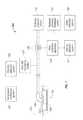
- reduced pressure source 110may include a pump that is driven by a chemical reaction.
- a tablet, solution, spray, or other delivery mechanismmay be delivered to the pump and used to initiate the chemical reaction.
- the heat generated by the chemical reactionmay be used to drive the pump to produce the reduced pressure.
- a pressurized gas cylindersuch as a CO 2 cylinder is used to drive a pump to produce the reduced pressure.
- reduced pressure source 110may be a battery-driven pump.
- the pumpuses low amounts of power and is capable of operating for an extended period of time on a single charge of the battery.
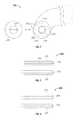
- Absorbent core 1325may be able to move within lumen 1410 .
- absorbent core 1325may be able to move in the directions indicated by multi-directional arrows 1345 .
- the movement of absorbent core 1325such as when delivery tube 1300 is being flexed, may facilitate the movement of liquid between recesses, and may also facilitate the transmission of reduced pressure.
Landscapes
- Health & Medical Sciences (AREA)
- Life Sciences & Earth Sciences (AREA)
- Heart & Thoracic Surgery (AREA)
- Animal Behavior & Ethology (AREA)
- Veterinary Medicine (AREA)
- Public Health (AREA)
- Engineering & Computer Science (AREA)
- Biomedical Technology (AREA)
- General Health & Medical Sciences (AREA)
- Anesthesiology (AREA)
- Hematology (AREA)
- Vascular Medicine (AREA)
- Pulmonology (AREA)
- Biophysics (AREA)
- Otolaryngology (AREA)
- Media Introduction/Drainage Providing Device (AREA)
- External Artificial Organs (AREA)
- Materials For Medical Uses (AREA)
- Surgical Instruments (AREA)
- Absorbent Articles And Supports Therefor (AREA)
- Agricultural Chemicals And Associated Chemicals (AREA)
Abstract
Description
Claims (19)
Priority Applications (13)
| Application Number | Priority Date | Filing Date | Title |
|---|---|---|---|
| US12/275,417US8267908B2 (en) | 2007-02-09 | 2008-11-21 | Delivery tube, system, and method for storing liquid from a tissue site |
| RU2011116450/14ARU2011116450A (en) | 2008-11-21 | 2009-11-18 | DELIVERY TUBE, SYSTEM AND METHOD FOR STORING LIQUID FROM A FABRIC AREA |
| PCT/US2009/064972WO2010059712A2 (en) | 2008-11-21 | 2009-11-18 | Delivery tube, system, and method for storing liquid from a tissue site |
| BRPI0916144ABRPI0916144A2 (en) | 2008-11-21 | 2009-11-18 | system for storing liquid from a tissue site, apparatus for storing liquid from a tissue site, method for storing liquid from a tissue site and method of manufacturing an application tube for storing liquid from a tissue site '' |
| AU2009316703AAU2009316703B2 (en) | 2008-11-21 | 2009-11-18 | Delivery tube, system, and method for storing liquid from a tissue site |
| KR1020117014087AKR101185995B1 (en) | 2008-11-21 | 2009-11-18 | Delivery tube, system, and method for storing liquid from a tissue site |
| EP09828160.3AEP2346561B1 (en) | 2008-11-21 | 2009-11-18 | Delivery tube, system, and method for storing liquid from a tissue site |
| CA2743645ACA2743645C (en) | 2008-11-21 | 2009-11-18 | Delivery tube, system, and method for storing liquid from a tissue site |
| CN201410067301.6ACN103877669B (en) | 2008-11-21 | 2009-11-18 | For storing the dispatch tube of the liquid from tissue site, system and method |
| JP2011537579AJP5939610B2 (en) | 2008-11-21 | 2009-11-18 | Delivery tube, system and method for retaining liquid from a tissue site |
| MX2011005290AMX2011005290A (en) | 2008-11-21 | 2009-11-18 | Delivery tube, system, and method for storing liquid from a tissue site. |
| CN200980145640.9ACN102215897B (en) | 2008-11-21 | 2009-11-18 | Delivery tube, system and method for storing liquid from a tissue site |
| JP2014246851AJP6096166B2 (en) | 2008-11-21 | 2014-12-05 | Delivery tube, system and method for retaining liquid from a tissue site |
Applications Claiming Priority (3)
| Application Number | Priority Date | Filing Date | Title |
|---|---|---|---|
| US90041507P | 2007-02-09 | 2007-02-09 | |
| US12/069,363US8057449B2 (en) | 2007-02-09 | 2008-02-08 | Apparatus and method for administering reduced pressure treatment to a tissue site |
| US12/275,417US8267908B2 (en) | 2007-02-09 | 2008-11-21 | Delivery tube, system, and method for storing liquid from a tissue site |
Related Parent Applications (1)
| Application Number | Title | Priority Date | Filing Date |
|---|---|---|---|
| US12/069,363Continuation-In-PartUS8057449B2 (en) | 2007-02-09 | 2008-02-08 | Apparatus and method for administering reduced pressure treatment to a tissue site |
Publications (2)
| Publication Number | Publication Date |
|---|---|
| US20090124988A1 US20090124988A1 (en) | 2009-05-14 |
| US8267908B2true US8267908B2 (en) | 2012-09-18 |
Family
ID=42198785
Family Applications (1)
| Application Number | Title | Priority Date | Filing Date |
|---|---|---|---|
| US12/275,417Active2029-09-08US8267908B2 (en) | 2007-02-09 | 2008-11-21 | Delivery tube, system, and method for storing liquid from a tissue site |
Country Status (11)
| Country | Link |
|---|---|
| US (1) | US8267908B2 (en) |
| EP (1) | EP2346561B1 (en) |
| JP (2) | JP5939610B2 (en) |
| KR (1) | KR101185995B1 (en) |
| CN (2) | CN102215897B (en) |
| AU (1) | AU2009316703B2 (en) |
| BR (1) | BRPI0916144A2 (en) |
| CA (1) | CA2743645C (en) |
| MX (1) | MX2011005290A (en) |
| RU (1) | RU2011116450A (en) |
| WO (1) | WO2010059712A2 (en) |
Cited By (29)
| Publication number | Priority date | Publication date | Assignee | Title |
|---|---|---|---|---|
| US20130085414A1 (en)* | 2011-09-30 | 2013-04-04 | Olympus Medical Systems Corporation | Method of taking out liquid present inside subject therefrom |
| US8986269B2 (en) | 2010-11-11 | 2015-03-24 | Ulcerx Medical Inc. | Wound leakage vacuum collection device |
| US9033942B2 (en) | 2008-03-07 | 2015-05-19 | Smith & Nephew, Inc. | Wound dressing port and associated wound dressing |
| US9446178B2 (en) | 2003-10-28 | 2016-09-20 | Smith & Nephew Plc | Wound cleansing apparatus in-situ |
| US9844473B2 (en) | 2002-10-28 | 2017-12-19 | Smith & Nephew Plc | Apparatus for aspirating, irrigating and cleansing wounds |
| USD806256S1 (en) | 2012-05-23 | 2017-12-26 | Smith & Nephew Plc | Medical dressing |
| US9889241B2 (en) | 2009-06-01 | 2018-02-13 | Smith & Nephew, Inc. | System for providing continual drainage in negative pressure wound therapy |
| US9962474B2 (en) | 2007-11-21 | 2018-05-08 | Smith & Nephew Plc | Vacuum assisted wound dressing |
| USRE46825E1 (en) | 2009-01-20 | 2018-05-08 | Smith & Nephew, Inc. | Method and apparatus for bridging from a dressing in negative pressure wound therapy |
| US10016545B2 (en) | 2008-07-21 | 2018-07-10 | Smith & Nephew, Inc. | Thin film wound dressing |
| US10076449B2 (en) | 2012-08-01 | 2018-09-18 | Smith & Nephew Plc | Wound dressing and method of treatment |
| US10130526B2 (en) | 2006-09-28 | 2018-11-20 | Smith & Nephew, Inc. | Portable wound therapy system |
| US10159604B2 (en) | 2010-04-27 | 2018-12-25 | Smith & Nephew Plc | Wound dressing and method of use |
| US10188555B2 (en) | 2008-03-13 | 2019-01-29 | Smith & Nephew, Inc. | Shear resistant wound dressing for use in vacuum wound therapy |
| US10201644B2 (en) | 2005-09-07 | 2019-02-12 | Smith & Nephew, Inc. | Self contained wound dressing with micropump |
| US10231875B2 (en) | 2007-11-21 | 2019-03-19 | Smith & Nephew Plc | Wound dressing |
| US10391212B2 (en) | 2006-05-11 | 2019-08-27 | Smith & Nephew, Inc. | Device and method for wound therapy |
| US10406037B2 (en) | 2009-12-22 | 2019-09-10 | Smith & Nephew, Inc. | Apparatuses and methods for negative pressure wound therapy |
| US10537706B2 (en) | 2012-02-28 | 2020-01-21 | Sumitomo Bakelite Co., Ltd. | Method for manufacturing medical instrument, and medical instrument |
| US10561769B2 (en) | 2007-12-06 | 2020-02-18 | Smith & Nephew Plc | Apparatus for topical negative pressure therapy |
| US10667955B2 (en) | 2012-08-01 | 2020-06-02 | Smith & Nephew Plc | Wound dressing and method of treatment |
| US10675392B2 (en) | 2007-12-06 | 2020-06-09 | Smith & Nephew Plc | Wound management |
| USRE48282E1 (en) | 2010-10-15 | 2020-10-27 | Smith & Nephew Plc | Medical dressing |
| US11253399B2 (en) | 2007-12-06 | 2022-02-22 | Smith & Nephew Plc | Wound filling apparatuses and methods |
| USRE49227E1 (en) | 2010-10-15 | 2022-10-04 | Smith & Nephew Plc | Medical dressing |
| US11607346B2 (en) | 2017-11-01 | 2023-03-21 | Smith & Nephew Plc | Dressing for negative pressure wound therapy with filter |
| US11819386B2 (en) | 2018-07-12 | 2023-11-21 | T.J.Smith And Nephew, Limited | Apparatuses and methods for negative pressure wound therapy |
| US12016993B2 (en) | 2020-01-15 | 2024-06-25 | T.J.Smith And Nephew, Limited | Fluidic connectors for negative pressure wound therapy |
| US12102512B2 (en) | 2007-12-06 | 2024-10-01 | Smith & Nephew Plc | Wound filling apparatuses and methods |
Families Citing this family (65)
| Publication number | Priority date | Publication date | Assignee | Title |
|---|---|---|---|---|
| US7846141B2 (en) | 2002-09-03 | 2010-12-07 | Bluesky Medical Group Incorporated | Reduced pressure treatment system |
| US11298453B2 (en) | 2003-10-28 | 2022-04-12 | Smith & Nephew Plc | Apparatus and method for wound cleansing with actives |
| US8062272B2 (en) | 2004-05-21 | 2011-11-22 | Bluesky Medical Group Incorporated | Flexible reduced pressure treatment appliance |
| US7909805B2 (en) | 2004-04-05 | 2011-03-22 | Bluesky Medical Group Incorporated | Flexible reduced pressure treatment appliance |
| US10058642B2 (en) | 2004-04-05 | 2018-08-28 | Bluesky Medical Group Incorporated | Reduced pressure treatment system |
| GB0508531D0 (en) | 2005-04-27 | 2005-06-01 | Smith & Nephew | Sai with ultrasound |
| CA2619925A1 (en) | 2005-09-07 | 2007-03-15 | Tyco Healthcare Group Lp | Wound dressing with vacuum reservoir |
| WO2009067711A2 (en) | 2007-11-21 | 2009-05-28 | T.J. Smith & Nephew, Limited | Suction device and dressing |
| EP2214612B1 (en) | 2007-11-21 | 2019-05-01 | Smith & Nephew PLC | Wound dressing |
| GB2455962A (en) | 2007-12-24 | 2009-07-01 | Ethicon Inc | Reinforced adhesive backing sheet, for plaster |
| AU2009221772B2 (en) | 2008-03-05 | 2015-01-22 | Solventum Intellectual Properties Company | Dressing and method for applying reduced pressure to and collecting and storing fluid from a tissue site |
| JP5122658B2 (en)* | 2008-03-13 | 2013-01-16 | ケーシーアイ ライセンシング インコーポレイテッド | System and method for applying reduced pressure |
| ES2658263T3 (en) | 2008-08-08 | 2018-03-09 | Smith & Nephew, Inc. | Continuous fiber wound dressing |
| US20100324516A1 (en) | 2009-06-18 | 2010-12-23 | Tyco Healthcare Group Lp | Apparatus for Vacuum Bridging and/or Exudate Collection |
| US8529526B2 (en) | 2009-10-20 | 2013-09-10 | Kci Licensing, Inc. | Dressing reduced-pressure indicators, systems, and methods |
| US8814842B2 (en) | 2010-03-16 | 2014-08-26 | Kci Licensing, Inc. | Delivery-and-fluid-storage bridges for use with reduced-pressure systems |
| US8604265B2 (en)* | 2010-04-16 | 2013-12-10 | Kci Licensing, Inc. | Dressings and methods for treating a tissue site on a patient |
| USRE48117E1 (en) | 2010-05-07 | 2020-07-28 | Smith & Nephew, Inc. | Apparatuses and methods for negative pressure wound therapy |
| RU2016111981A (en) | 2010-12-22 | 2018-11-27 | Смит Энд Нефью, Инк. | DEVICE AND METHOD FOR TREATING RAS WITH NEGATIVE PRESSURE |
| USD714433S1 (en) | 2010-12-22 | 2014-09-30 | Smith & Nephew, Inc. | Suction adapter |
| GB2488749A (en) | 2011-01-31 | 2012-09-12 | Systagenix Wound Man Ip Co Bv | Laminated silicone coated wound dressing |
| GB201106491D0 (en) | 2011-04-15 | 2011-06-01 | Systagenix Wound Man Ip Co Bv | Patterened silicone coating |
| EP2776084B1 (en)* | 2011-11-11 | 2015-10-28 | KCI Licensing, Inc. | Reduced-pressure, tunnel-wound dressings, systems, and methods |
| DE102011055782A1 (en)* | 2011-11-28 | 2013-05-29 | Birgit Riesinger | WOUND CARE DEVICE FOR TREATING WOUNDS USING ATMOSPHERIC UNDERPRESSURE |
| CN103987348B (en) | 2011-12-16 | 2016-05-11 | 凯希特许有限公司 | Releasable Medical Drapes |
| US10940047B2 (en) | 2011-12-16 | 2021-03-09 | Kci Licensing, Inc. | Sealing systems and methods employing a hybrid switchable drape |
| AU2013344686B2 (en) | 2012-11-16 | 2018-06-21 | Solventum Intellectual Properties Company | Medical drape with pattern adhesive layers and method of manufacturing same |
| US20140275864A1 (en)* | 2013-03-15 | 2014-09-18 | Hydrofera, Llc | Polyurethane dressing and method for making same |
| GB201222770D0 (en) | 2012-12-18 | 2013-01-30 | Systagenix Wound Man Ip Co Bv | Wound dressing with adhesive margin |
| EP2968012B1 (en) | 2013-03-14 | 2017-04-26 | KCI Licensing, Inc. | Absorbent dressing with hybrid drape |
| US10010658B2 (en) | 2013-05-10 | 2018-07-03 | Smith & Nephew Plc | Fluidic connector for irrigation and aspiration of wounds |
| US9486603B2 (en) | 2013-06-20 | 2016-11-08 | Philip J. Dye | Intermittent urinary catheter |
| US9878125B2 (en) | 2013-06-20 | 2018-01-30 | Zcath Llc | Intermittent urinary catheter |
| US9289575B2 (en) | 2013-06-20 | 2016-03-22 | Philip J. Dye | Catheter |
| EP3038667B1 (en) | 2013-08-26 | 2019-10-09 | KCI Licensing, Inc. | Dressing interface with moisture controlling feature and sealing function |
| US10946124B2 (en) | 2013-10-28 | 2021-03-16 | Kci Licensing, Inc. | Hybrid sealing tape |
| US9956120B2 (en) | 2013-10-30 | 2018-05-01 | Kci Licensing, Inc. | Dressing with sealing and retention interface |
| EP3062751B1 (en) | 2013-10-30 | 2017-08-09 | KCI Licensing, Inc. | Condensate absorbing and dissipating system |
| EP3527237B1 (en)* | 2013-10-30 | 2020-09-09 | KCI Licensing, Inc. | Absorbent conduit and system |
| AU2014342903B2 (en) | 2013-10-30 | 2018-09-20 | Solventum Intellectual Properties Company | Dressing with differentially sized perforations |
| US10052416B2 (en)* | 2014-01-07 | 2018-08-21 | Mayo Foundation For Medical Education And Research | Enterocutaneous fistula treatment |
| EP3110379B1 (en) | 2014-02-28 | 2019-04-03 | KCI Licensing, Inc. | Hybrid drape having a gel-coated perforated mesh |
| US11026844B2 (en) | 2014-03-03 | 2021-06-08 | Kci Licensing, Inc. | Low profile flexible pressure transmission conduit |
| WO2015168681A1 (en) | 2014-05-02 | 2015-11-05 | Kci Licensing, Inc. | Fluid storage devices, systems, and methods |
| US11026847B2 (en) | 2014-06-02 | 2021-06-08 | Zdzislaw Harry Piotrowski | Systems and methods for wound healing |
| US10022274B1 (en)* | 2014-06-02 | 2018-07-17 | Zdzislaw Harry Piotrowski | Systems and methods for wound healing |
| JP6640748B2 (en) | 2014-06-05 | 2020-02-05 | ケーシーアイ ライセンシング インコーポレイテッド | Dressing with fluid acquisition and dispensing features |
| WO2016025859A2 (en) | 2014-08-14 | 2016-02-18 | Soneter, Inc. | Devices and system for channeling and automatic monitoring of fluid flow in fluid distribution systems |
| AU2015301406B2 (en) | 2014-08-14 | 2020-07-16 | Reliance Worldwide Corporation | Methods and apparatus for fluid flow monitoring and leak detection |
| WO2016069890A1 (en)* | 2014-10-29 | 2016-05-06 | Shakam LLC | Negative pressure wound therapy dressing and drainage apparatus and system |
| WO2016100098A1 (en) | 2014-12-17 | 2016-06-23 | Kci Licensing, Inc. | Dressing with offloading capability |
| EP3574877B1 (en) | 2015-05-08 | 2022-08-17 | 3M Innovative Properties Company | Low-acuity dressing with integral pump |
| US10076594B2 (en) | 2015-05-18 | 2018-09-18 | Smith & Nephew Plc | Fluidic connector for negative pressure wound therapy |
| EP3741335B1 (en) | 2015-09-01 | 2023-05-24 | KCI Licensing, Inc. | Dressing with increased apposition force |
| EP3349807B1 (en) | 2015-09-17 | 2021-02-24 | 3M Innovative Properties Company | Hybrid silicone and acrylic adhesive cover for use with wound treatment |
| KR102545969B1 (en)* | 2016-10-26 | 2023-06-20 | 나이키 이노베이트 씨.브이. | Article of footwear |
| CN107569314A (en)* | 2017-10-24 | 2018-01-12 | 南京医创星信息技术有限公司 | A kind of artificial anus bag of Auto-drainage exhaust |
| IT201700120992A1 (en)* | 2017-10-25 | 2019-04-25 | S2Medical Ab | APPARATUS FOR NEGATIVE PRESSURE THERAPY FOR WOUNDS. |
| GB201820927D0 (en) | 2018-12-21 | 2019-02-06 | Smith & Nephew | Wound therapy systems and methods with supercapacitors |
| EP4017551B1 (en)* | 2019-08-20 | 2024-12-18 | Solventum Intellectual Properties Company | System and method to clear conduits of fluids after instillation to a wound |
| EP4559504A3 (en)* | 2020-04-06 | 2025-08-13 | Edwards Lifesciences Corporation | Prosthetic heart valve delivery apparatus |
| KR102470836B1 (en)* | 2020-11-10 | 2022-11-25 | 경기대학교 산학협력단 | Artificial intelligence based continuous process control device, method of predicting quality and improving yield using the same |
| CN112915310A (en)* | 2021-01-26 | 2021-06-08 | 浙江清华柔性电子技术研究院 | In-vivo implantable peristaltic pump, peristaltic pump controller and body fluid transfer system |
| WO2022164958A1 (en)* | 2021-01-28 | 2022-08-04 | The Board Of Trustees Of The University Of Illinois | Medical device-related pressure injury prevention pressure-indicating material |
| DE102022133931A1 (en)* | 2022-12-19 | 2024-06-20 | Paul Hartmann Ag | Connection device for the vacuum-tight fluidic connection of a negative pressure wound dressing with a negative pressure source, negative pressure wound therapy kit and negative pressure wound therapy system |
Citations (230)
| Publication number | Priority date | Publication date | Assignee | Title |
|---|---|---|---|---|
| US1355846A (en) | 1920-02-06 | 1920-10-19 | David A Rannells | Medical appliance |
| US2547758A (en) | 1949-01-05 | 1951-04-03 | Wilmer B Keeling | Instrument for treating the male urethra |
| US2632443A (en) | 1949-04-18 | 1953-03-24 | Eleanor P Lesher | Surgical dressing |
| GB692578A (en) | 1949-09-13 | 1953-06-10 | Minnesota Mining & Mfg | Improvements in or relating to drape sheets for surgical use |
| US2682873A (en) | 1952-07-30 | 1954-07-06 | Johnson & Johnson | General purpose protective dressing |
| US2910763A (en) | 1955-08-17 | 1959-11-03 | Du Pont | Felt-like products |
| US2969057A (en) | 1957-11-04 | 1961-01-24 | Brady Co W H | Nematodic swab |
| US3066672A (en) | 1960-09-27 | 1962-12-04 | Jr William H Crosby | Method and apparatus for serial sampling of intestinal juice |
| US3367332A (en) | 1965-08-27 | 1968-02-06 | Gen Electric | Product and process for establishing a sterile area of skin |
| US3376868A (en) | 1964-06-04 | 1968-04-09 | Howe Sound Co | Surgical evacuator device |
| US3382867A (en) | 1965-03-22 | 1968-05-14 | Ruby L. Reaves | Body portion developing device with combined vacuum and vibrating means |
| US3520300A (en) | 1967-03-15 | 1970-07-14 | Amp Inc | Surgical sponge and suction device |
| US3568675A (en) | 1968-08-30 | 1971-03-09 | Clyde B Harvey | Fistula and penetrating wound dressing |
| US3648692A (en) | 1970-12-07 | 1972-03-14 | Parke Davis & Co | Medical-surgical dressing for burns and the like |
| US3682180A (en) | 1970-06-08 | 1972-08-08 | Coilform Co Inc | Drain clip for surgical drain |
| US3742952A (en) | 1971-04-28 | 1973-07-03 | Alpha Ind Inc | Surgical suction pump assembly |
| US3774611A (en) | 1972-06-08 | 1973-11-27 | J Tussey | Stabilized contamination free surgical evacuator |
| US3779243A (en) | 1971-10-15 | 1973-12-18 | J Tussey | Contamination free surgical evacuator |
| US3823716A (en) | 1972-08-14 | 1974-07-16 | Simpla Plastics | Urinary drainage devices |
| US3826254A (en) | 1973-02-26 | 1974-07-30 | Verco Ind | Needle or catheter retaining appliance |
| US3875941A (en) | 1974-04-03 | 1975-04-08 | Medical Dynamics Inc | System for evacuating fluids from the body |
| US3957054A (en)* | 1973-09-26 | 1976-05-18 | Mcfarlane Richard H | Surgical drainage tube |
| DE2640413A1 (en) | 1976-09-08 | 1978-03-09 | Wolf Gmbh Richard | CATHETER MONITORING DEVICE |
| US4080970A (en) | 1976-11-17 | 1978-03-28 | Miller Thomas J | Post-operative combination dressing and internal drain tube with external shield and tube connector |
| US4096853A (en) | 1975-06-21 | 1978-06-27 | Hoechst Aktiengesellschaft | Device for the introduction of contrast medium into an anus praeter |
| US4139004A (en) | 1977-02-17 | 1979-02-13 | Gonzalez Jr Harry | Bandage apparatus for treating burns |
| US4141361A (en) | 1970-02-09 | 1979-02-27 | Snyder Manufacturing Co., Incorporated | Evacuator |
| US4165748A (en) | 1977-11-07 | 1979-08-28 | Johnson Melissa C | Catheter tube holder |
| US4184510A (en) | 1977-03-15 | 1980-01-22 | Fibra-Sonics, Inc. | Valued device for controlling vacuum in surgery |
| US4233969A (en) | 1976-11-11 | 1980-11-18 | Lock Peter M | Wound dressing materials |
| US4245630A (en) | 1976-10-08 | 1981-01-20 | T. J. Smith & Nephew, Ltd. | Tearable composite strip of materials |
| US4250882A (en) | 1979-01-26 | 1981-02-17 | Medical Dynamics, Inc. | Wound drainage device |
| US4256109A (en) | 1978-07-10 | 1981-03-17 | Nichols Robert L | Shut off valve for medical suction apparatus |
| US4261363A (en) | 1979-11-09 | 1981-04-14 | C. R. Bard, Inc. | Retention clips for body fluid drains |
| US4275721A (en) | 1978-11-28 | 1981-06-30 | Landstingens Inkopscentral Lic, Ekonomisk Forening | Vein catheter bandage |
| US4284079A (en) | 1979-06-28 | 1981-08-18 | Adair Edwin Lloyd | Method for applying a male incontinence device |
| US4297995A (en) | 1980-06-03 | 1981-11-03 | Key Pharmaceuticals, Inc. | Bandage containing attachment post |
| US4329743A (en) | 1979-04-27 | 1982-05-18 | College Of Medicine And Dentistry Of New Jersey | Bio-absorbable composite tissue scaffold |
| US4333468A (en) | 1980-08-18 | 1982-06-08 | Geist Robert W | Mesentery tube holder apparatus |
| US4373519A (en) | 1981-06-26 | 1983-02-15 | Minnesota Mining And Manufacturing Company | Composite wound dressing |
| US4382441A (en) | 1978-12-06 | 1983-05-10 | Svedman Paul | Device for treating tissues, for example skin |
| JPS5895841U (en) | 1981-12-21 | 1983-06-29 | 住友ベークライト株式会社 | Medical body fluid drain tube |
| US4392853A (en) | 1981-03-16 | 1983-07-12 | Rudolph Muto | Sterile assembly for protecting and fastening an indwelling device |
| US4392858A (en) | 1981-07-16 | 1983-07-12 | Sherwood Medical Company | Wound drainage device |
| US4419097A (en) | 1981-07-31 | 1983-12-06 | Rexar Industries, Inc. | Attachment for catheter tube |
| EP0100148A1 (en) | 1982-07-06 | 1984-02-08 | Dow Corning Limited | Medical-surgical dressing and a process for the production thereof |
| US4433973A (en) | 1982-01-12 | 1984-02-28 | Bioresearch Inc. | Reusable tube connector assembly |
| US4465485A (en) | 1981-03-06 | 1984-08-14 | Becton, Dickinson And Company | Suction canister with unitary shut-off valve and filter features |
| EP0117632A2 (en) | 1983-01-27 | 1984-09-05 | Johnson & Johnson Products Inc. | Adhesive film dressing |
| US4475909A (en) | 1982-05-06 | 1984-10-09 | Eisenberg Melvin I | Male urinary device and method for applying the device |
| US4480638A (en) | 1980-03-11 | 1984-11-06 | Eduard Schmid | Cushion for holding an element of grafted skin |
| US4523920A (en) | 1983-12-05 | 1985-06-18 | Sil-Fab Corporation | Surgical suction drain |
| US4525374A (en) | 1984-02-27 | 1985-06-25 | Manresa, Inc. | Treating hydrophobic filters to render them hydrophilic |
| US4525166A (en) | 1981-11-21 | 1985-06-25 | Intermedicat Gmbh | Rolled flexible medical suction drainage device |
| US4529402A (en) | 1980-07-08 | 1985-07-16 | Snyder Laboratories, Inc. | Closed wound suction evacuator with rotary valve |
| US4540412A (en) | 1983-07-14 | 1985-09-10 | The Kendall Company | Device for moist heat therapy |
| US4543100A (en) | 1983-11-01 | 1985-09-24 | Brodsky Stuart A | Catheter and drain tube retainer |
| US4548202A (en) | 1983-06-20 | 1985-10-22 | Ethicon, Inc. | Mesh tissue fasteners |
| US4551139A (en) | 1982-02-08 | 1985-11-05 | Marion Laboratories, Inc. | Method and apparatus for burn wound treatment |
| EP0161865A2 (en) | 1984-05-03 | 1985-11-21 | Smith and Nephew Associated Companies p.l.c. | Adhesive wound dressing |
| US4569348A (en) | 1980-02-22 | 1986-02-11 | Velcro Usa Inc. | Catheter tube holder strap |
| US4573965A (en) | 1984-02-13 | 1986-03-04 | Superior Plastic Products Corp. | Device for draining wounds |
| US4579555A (en) | 1983-12-05 | 1986-04-01 | Sil-Fab Corporation | Surgical gravity drain having aligned longitudinally extending capillary drainage channels |
| US4605399A (en) | 1984-12-04 | 1986-08-12 | Complex, Inc. | Transdermal infusion device |
| US4608041A (en) | 1981-10-14 | 1986-08-26 | Frese Nielsen | Device for treatment of wounds in body tissue of patients by exposure to jets of gas |
| US4640688A (en) | 1985-08-23 | 1987-02-03 | Mentor Corporation | Urine collection catheter |
| US4642093A (en) | 1984-02-08 | 1987-02-10 | Haerle Anton | Aspirator for withdrawal of secretions from wounds |
| US4643719A (en) | 1984-07-19 | 1987-02-17 | Garth Geoffrey C | Manually operable aspirator |
| US4655754A (en) | 1984-11-09 | 1987-04-07 | Stryker Corporation | Vacuum wound drainage system and lipids baffle therefor |
| US4664652A (en) | 1985-02-07 | 1987-05-12 | Snyder Laboratories, Inc. | Wound evacuator |
| US4664662A (en) | 1984-08-02 | 1987-05-12 | Smith And Nephew Associated Companies Plc | Wound dressing |
| US4710165A (en) | 1985-09-16 | 1987-12-01 | Mcneil Charles B | Wearable, variable rate suction/collection device |
| US4733659A (en) | 1986-01-17 | 1988-03-29 | Seton Company | Foam bandage |
| GB2195255A (en) | 1986-09-30 | 1988-04-07 | Vacutec Uk Limited | Method and apparatus for vacuum treatment of an epidermal surface |
| US4743232A (en) | 1986-10-06 | 1988-05-10 | The Clinipad Corporation | Package assembly for plastic film bandage |
| GB2197789A (en) | 1986-11-28 | 1988-06-02 | Smiths Industries Plc | Anti-foaming disinfectants used in surgical suction apparatus |
| US4758220A (en) | 1985-09-26 | 1988-07-19 | Alcon Laboratories, Inc. | Surgical cassette proximity sensing and latching apparatus |
| US4787888A (en) | 1987-06-01 | 1988-11-29 | University Of Connecticut | Disposable piezoelectric polymer bandage for percutaneous delivery of drugs and method for such percutaneous delivery (a) |
| US4826494A (en) | 1984-11-09 | 1989-05-02 | Stryker Corporation | Vacuum wound drainage system |
| US4838883A (en) | 1986-03-07 | 1989-06-13 | Nissho Corporation | Urine-collecting device |
| US4840187A (en) | 1986-09-11 | 1989-06-20 | Bard Limited | Sheath applicator |
| US4863449A (en) | 1987-07-06 | 1989-09-05 | Hollister Incorporated | Adhesive-lined elastic condom cathether |
| US4872450A (en) | 1984-08-17 | 1989-10-10 | Austad Eric D | Wound dressing and method of forming same |
| US4878901A (en) | 1986-10-10 | 1989-11-07 | Sachse Hans Ernst | Condom catheter, a urethral catheter for the prevention of ascending infections |
| GB2220357A (en) | 1988-05-28 | 1990-01-10 | Smiths Industries Plc | Medico-surgical containers |
| US4897081A (en) | 1984-05-25 | 1990-01-30 | Thermedics Inc. | Percutaneous access device |
| US4906240A (en) | 1988-02-01 | 1990-03-06 | Matrix Medica, Inc. | Adhesive-faced porous absorbent sheet and method of making same |
| US4906233A (en) | 1986-05-29 | 1990-03-06 | Terumo Kabushiki Kaisha | Method of securing a catheter body to a human skin surface |
| US4919654A (en) | 1988-08-03 | 1990-04-24 | Kalt Medical Corporation | IV clamp with membrane |
| CA2005436A1 (en) | 1988-12-13 | 1990-06-13 | Glenda G. Kalt | Transparent tracheostomy tube dressing |
| US4941882A (en) | 1987-03-14 | 1990-07-17 | Smith And Nephew Associated Companies, P.L.C. | Adhesive dressing for retaining a cannula on the skin |
| US4953565A (en) | 1986-11-26 | 1990-09-04 | Shunro Tachibana | Endermic application kits for external medicines |
| US4969880A (en) | 1989-04-03 | 1990-11-13 | Zamierowski David S | Wound dressing and treatment method |
| US4981474A (en) | 1988-02-16 | 1991-01-01 | Baxter Travenol Laboratories, Inc. | Body fluid drainage device |
| US4985019A (en) | 1988-03-11 | 1991-01-15 | Michelson Gary K | X-ray marker |
| GB2235877A (en) | 1989-09-18 | 1991-03-20 | Antonio Talluri | Closed wound suction apparatus |
| US5013300A (en) | 1989-03-09 | 1991-05-07 | Williams James D | Apparatus for suction lipectomy surgery |
| US5019059A (en) | 1986-12-15 | 1991-05-28 | Uresil Corporation | Apparatus and method for collecting body fluids |
| US5034006A (en) | 1987-06-22 | 1991-07-23 | Takeda Chemical Industries, Ltd. | Suction equipment for medical operation |
| US5037397A (en) | 1985-05-03 | 1991-08-06 | Medical Distributors, Inc. | Universal clamp |
| US5086170A (en) | 1989-01-16 | 1992-02-04 | Roussel Uclaf | Process for the preparation of azabicyclo compounds |
| US5092858A (en) | 1990-03-20 | 1992-03-03 | Becton, Dickinson And Company | Liquid gelling agent distributor device |
| US5100396A (en) | 1989-04-03 | 1992-03-31 | Zamierowski David S | Fluidic connection system and method |
| US5100395A (en) | 1989-10-06 | 1992-03-31 | Lior Rosenberg | Fluid drain for wounds |
| US5102404A (en) | 1986-12-15 | 1992-04-07 | Uresil Corporation | Apparatus and method for collecting body fluids |
| US5108364A (en) | 1989-02-16 | 1992-04-28 | Sumitomo Bakelte Company Limited | Monitoring catheter for medical use |
| US5112323A (en) | 1990-02-08 | 1992-05-12 | Snyder Laboratories, Inc. | Wound evacuator |
| US5116310A (en) | 1990-07-30 | 1992-05-26 | Helix Medical, Inc. | Multiple lumen wound drain with bypass openings |
| US5134994A (en) | 1990-02-12 | 1992-08-04 | Say Sam L | Field aspirator in a soft pack with externally mounted container |
| US5149331A (en) | 1991-05-03 | 1992-09-22 | Ariel Ferdman | Method and device for wound closure |
| US5167613A (en) | 1992-03-23 | 1992-12-01 | The Kendall Company | Composite vented wound dressing |
| US5176663A (en) | 1987-12-02 | 1993-01-05 | Pal Svedman | Dressing having pad with compressibility limiting elements |
| US5215522A (en) | 1984-07-23 | 1993-06-01 | Ballard Medical Products | Single use medical aspirating device and method |
| US5232453A (en) | 1989-07-14 | 1993-08-03 | E. R. Squibb & Sons, Inc. | Catheter holder |
| US5259399A (en) | 1992-03-02 | 1993-11-09 | Alan Brown | Device and method of causing weight loss using removable variable volume intragastric bladder |
| US5261893A (en) | 1989-04-03 | 1993-11-16 | Zamierowski David S | Fastening system and method |
| US5266071A (en) | 1986-03-28 | 1993-11-30 | Nancy W. Elftman | Method for using percutaneous accessport |
| US5278100A (en) | 1991-11-08 | 1994-01-11 | Micron Technology, Inc. | Chemical vapor deposition technique for depositing titanium silicide on semiconductor wafers |
| US5279550A (en) | 1991-12-19 | 1994-01-18 | Gish Biomedical, Inc. | Orthopedic autotransfusion system |
| US5298015A (en) | 1989-07-11 | 1994-03-29 | Nippon Zeon Co., Ltd. | Wound dressing having a porous structure |
| US5342376A (en) | 1993-05-03 | 1994-08-30 | Dermagraphics, Inc. | Inserting device for a barbed tissue connector |
| US5342329A (en) | 1991-10-11 | 1994-08-30 | Inmed Ltda. | Portable disposable device for post-surgical suction |
| US5344415A (en) | 1993-06-15 | 1994-09-06 | Deroyal Industries, Inc. | Sterile system for dressing vascular access site |
| DE4306478A1 (en) | 1993-03-02 | 1994-09-08 | Wolfgang Dr Wagner | Drainage device, in particular pleural drainage device, and drainage method |
| US5358494A (en) | 1989-07-11 | 1994-10-25 | Svedman Paul | Irrigation dressing |
| US5405322A (en) | 1993-08-12 | 1995-04-11 | Boston Scientific Corporation | Method for treating aneurysms with a thermal source |
| US5437622A (en) | 1992-04-29 | 1995-08-01 | Laboratoire Hydrex (Sa) | Transparent adhesive dressing with reinforced starter cuts |
| US5437651A (en) | 1993-09-01 | 1995-08-01 | Research Medical, Inc. | Medical suction apparatus |
| DE29504378U1 (en) | 1995-03-15 | 1995-09-14 | MTG Medizinisch, technische Gerätebau GmbH, 66299 Friedrichsthal | Electronically controlled low-vacuum pump for chest and wound drainage |
| US5470316A (en) | 1993-09-07 | 1995-11-28 | United States Surgical Corporation | Body tissue penetrating device having a vacuum indicator |
| US5527293A (en) | 1989-04-03 | 1996-06-18 | Kinetic Concepts, Inc. | Fastening system and method |
| US5549584A (en) | 1994-02-14 | 1996-08-27 | The Kendall Company | Apparatus for removing fluid from a wound |
| US5549579A (en) | 1992-11-20 | 1996-08-27 | Specialty Silicone Fabricators | Unitary drain and method for making |
| US5556375A (en) | 1994-06-16 | 1996-09-17 | Hercules Incorporated | Wound dressing having a fenestrated base layer |
| US5569184A (en) | 1992-04-29 | 1996-10-29 | Cardiovascular Dynamics, Inc. | Delivery and balloon dilatation catheter and method of using |
| US5607388A (en) | 1994-06-16 | 1997-03-04 | Hercules Incorporated | Multi-purpose wound dressing |
| US5636643A (en) | 1991-11-14 | 1997-06-10 | Wake Forest University | Wound treatment employing reduced pressure |
| US5643589A (en) | 1992-12-04 | 1997-07-01 | Chalmers; Susanna Elizabeth | Desiccant formulated for treating wounds or lesions |
| US5645081A (en) | 1991-11-14 | 1997-07-08 | Wake Forest University | Method of treating tissue damage and apparatus for same |
| US5676634A (en) | 1994-03-30 | 1997-10-14 | Khouri Biomedical Research, Inc. | Method and apparatus for soft tissue enlargement with balanced force appliance |
| US5713874A (en) | 1995-08-01 | 1998-02-03 | Kind-R-Ject Company, Llc | Camouflaged injection needle |
| US5735833A (en) | 1996-12-11 | 1998-04-07 | Bristol-Myers Squibb Co. | Lavage tip |
| US5762640A (en) | 1995-05-31 | 1998-06-09 | Nec Corporation | Effusion fluid sucking device |
| US5820581A (en) | 1994-08-19 | 1998-10-13 | Lifenet Research Foundation | Process for cleaning large bone grafts and bone grafts produced thereby |
| JPH11501837A (en) | 1995-03-16 | 1999-02-16 | オリジン・メドシステムズ・インク | Inflation device to separate tissue layers |
| US5914264A (en) | 1994-12-30 | 1999-06-22 | Reconstructive Technologies | Apparatus for growing vertebrate skin in vitro |
| GB2333965A (en) | 1997-09-12 | 1999-08-11 | Kci Medical Ltd | Surgical drape |
| US5941859A (en) | 1997-03-17 | 1999-08-24 | Lerman; Benjamin S. | Wound irrigation shield with fluid scavenging |
| US5980503A (en) | 1996-04-08 | 1999-11-09 | Guidant Corporation | Endoscopic cardioplegia infusion cannula and method of use |
| US5984942A (en) | 1997-04-02 | 1999-11-16 | Femrx, Inc. | Methods and systems for reducing tissue adhesion |
| US6042537A (en) | 1997-08-13 | 2000-03-28 | Kaiser; Daniel | Method and apparatus for tissue enlargement |
| US6071267A (en) | 1998-02-06 | 2000-06-06 | Kinetic Concepts, Inc. | Medical patient fluid management interface system and method |
| US6080243A (en) | 1998-06-18 | 2000-06-27 | 3M Innovative Properties Company | Fluid guide device having an open structure surface for attachement to a fluid transport source |
| US6135116A (en) | 1997-07-28 | 2000-10-24 | Kci Licensing, Inc. | Therapeutic method for treating ulcers |
| US6142982A (en) | 1995-11-14 | 2000-11-07 | Kci Medical Limited | Portable wound treatment apparatus |
| US6174306B1 (en) | 1995-05-13 | 2001-01-16 | Wim Fleischmann | Device for vacuum-sealing an injury |
| US6241747B1 (en) | 1993-05-03 | 2001-06-05 | Quill Medical, Inc. | Barbed Bodily tissue connector |
| US6287316B1 (en) | 1999-03-26 | 2001-09-11 | Ethicon, Inc. | Knitted surgical mesh |
| JP2001252349A (en) | 2000-03-09 | 2001-09-18 | Sachiko Yanagida | Tube for drainage |
| US6394948B1 (en) | 1995-09-20 | 2002-05-28 | Medtronic, Inc. | Method and apparatus for temporarily immobilizing a local area of tissue |
| US20020065494A1 (en) | 2000-11-29 | 2002-05-30 | Lockwood Jeffrey S. | Vacuum therapy and cleansing dressing for wounds |
| US6398767B1 (en) | 1997-05-27 | 2002-06-04 | Wilhelm Fleischmann | Process and device for application of active substances to a wound surface area |
| US20020077661A1 (en) | 2000-12-20 | 2002-06-20 | Vahid Saadat | Multi-barbed device for retaining tissue in apposition and methods of use |
| US20020115951A1 (en) | 2001-02-22 | 2002-08-22 | Core Products International, Inc. | Ankle brace providing upper and lower ankle adjustment |
| US20020120185A1 (en) | 2000-05-26 | 2002-08-29 | Kci Licensing, Inc. | System for combined transcutaneous blood gas monitoring and vacuum assisted wound closure |
| US6458109B1 (en) | 1998-08-07 | 2002-10-01 | Hill-Rom Services, Inc. | Wound treatment apparatus |
| US20020143286A1 (en) | 2001-03-05 | 2002-10-03 | Kci Licensing, Inc. | Vacuum assisted wound treatment apparatus and infection identification system and method |
| US20020161346A1 (en) | 2000-11-29 | 2002-10-31 | Lockwood Jeffrey S. | Vacuum therapy and cleansing dressing for wounds |
| US6478789B1 (en) | 1999-11-15 | 2002-11-12 | Allegiance Corporation | Wound drain with portals to enable uniform suction |
| US6488643B1 (en) | 1998-10-08 | 2002-12-03 | Kci Licensing, Inc. | Wound healing foot wrap |
| US6493568B1 (en) | 1994-07-19 | 2002-12-10 | Kci Licensing, Inc. | Patient interface system |
| AU755496B2 (en) | 1997-09-12 | 2002-12-12 | Kci Licensing, Inc. | Surgical drape and suction head for wound treatment |
| US20020198503A1 (en) | 2000-11-29 | 2002-12-26 | Risk James R. | Wound treatment apparatus |
| US20020198504A1 (en) | 2000-11-29 | 2002-12-26 | Risk James R. | Wound treatment apparatus |
| US6500112B1 (en) | 1994-03-30 | 2002-12-31 | Brava, Llc | Vacuum dome with supporting rim and rim cushion |
| US20030014022A1 (en) | 2001-07-12 | 2003-01-16 | Lockwood Jeffrey S. | Control of vacuum level rate of change |
| US20030057070A1 (en) | 2001-09-07 | 2003-03-27 | Shih-Chieh Wang | Power switch apparatus |
| US6551280B1 (en) | 2000-06-30 | 2003-04-22 | Embro Corporation | Therapeutic device and system |
| US20030088209A1 (en) | 2000-02-16 | 2003-05-08 | Jessica Chiu | Multi-lumen extrusion tubing |
| US6572594B2 (en) | 1999-08-18 | 2003-06-03 | R.S. Medical Equipment Llc | Skin treatment using neuromuscular stimulation and a treatment gas containing medicine |
| US6626891B2 (en) | 1997-07-03 | 2003-09-30 | Polymedics N.V. | Drainage system to be used with an open wound, an element which is used thereby for placing a drainage tube or hose, and a method of using said drainage system |
| US20030187367A1 (en) | 2002-03-22 | 2003-10-02 | Odland Rick Mathew | System for treating tissue swelling |
| TW558444B (en) | 2001-10-11 | 2003-10-21 | Hill Rom Services Inc | Waste container for negative pressure therapy |
| US6641553B1 (en) | 1999-06-02 | 2003-11-04 | Boston Scientific Corporation | Devices and methods for delivering a drug |
| US6641575B1 (en) | 1999-01-26 | 2003-11-04 | Neal M. Lonky | Surgical vacuum instrument for retracting, extracting, and manipulating tissue |
| US6648862B2 (en)* | 2001-11-20 | 2003-11-18 | Spheric Products, Ltd. | Personally portable vacuum desiccator |
| US20030216672A1 (en) | 2002-05-15 | 2003-11-20 | The Research Foundation Of State University Of New York | System and method for healing skin injuries |
| US6656149B2 (en) | 2000-04-13 | 2003-12-02 | Leland L. Ladd | Expansible medical suction canister |
| US20030225441A1 (en) | 2000-06-08 | 2003-12-04 | Kci Licensing, Inc. | Localized liquid therapy and thermotherapy device |
| US6660484B2 (en) | 1992-11-13 | 2003-12-09 | Regents Of The University Of California | Colorimetric glycopolythiophene biosensors |
| US20040006319A1 (en) | 1999-04-09 | 2004-01-08 | Lina Cesar Z. | Wound therapy device |
| US6682506B1 (en) | 1998-12-22 | 2004-01-27 | Francis Navarro | Device for maintaining at least a tube |
| US20040039406A1 (en) | 1998-06-01 | 2004-02-26 | Jessen Jonh W. | Method and apparatus for placing and maintaining a percutaneous tube into a body cavity |
| US20040064132A1 (en) | 2002-09-16 | 2004-04-01 | Boehringer John R. | Device for treating a wound |
| US20040093026A1 (en) | 2002-11-07 | 2004-05-13 | Rolf Weidenhagen | Endoscopic wound care treatment system and method |
| US6755796B2 (en) | 1999-02-07 | 2004-06-29 | Medispec Ltd. | Pressure-pulse therapy apparatus |
| US6755807B2 (en) | 1999-11-29 | 2004-06-29 | Hill-Rom Services, Inc. | Wound treatment apparatus |
| US6758836B2 (en) | 2002-02-07 | 2004-07-06 | C. R. Bard, Inc. | Split tip dialysis catheter |
| US20050004534A1 (en) | 2001-12-26 | 2005-01-06 | Lockwood Jeffery S | Vented vacuum bandage and method |
| US6840960B2 (en) | 2002-09-27 | 2005-01-11 | Stephen K. Bubb | Porous implant system and treatment method |
| US20050065484A1 (en) | 2003-09-10 | 2005-03-24 | Watson Richard L. | Wound healing apparatus with bioabsorbable material and suction tubes |
| US20050070858A1 (en) | 2002-04-10 | 2005-03-31 | Lockwood Jeffrey S | Access openings in vacuum bandage |
| US20050137539A1 (en) | 2002-09-13 | 2005-06-23 | Biggie John J. | Closed wound drainage system |
| US20050148913A1 (en) | 2004-01-02 | 2005-07-07 | Weston Richard S. | Reduced pressure wound treatment appliance |
| US20050171467A1 (en) | 2004-01-30 | 2005-08-04 | Jaime Landman | Multiple function surgical device |
| US20050203483A1 (en) | 1999-07-02 | 2005-09-15 | Pulmonx | Methods, systems, and kits for lung volume reduction |
| JP2005528167A (en) | 2002-06-03 | 2005-09-22 | ウェイク フォーレスト ユニバーシティ ヘルス サイエンシーズ | Directed tissue growth using reduced pressure |
| US20050245906A1 (en) | 2004-04-21 | 2005-11-03 | Exploramed Nc1, Inc. | Implantable device and methods for delivering drugs and other substances to treat sinusitis and other disorders |
| WO2005105180A1 (en) | 2004-04-28 | 2005-11-10 | Smith & Nephew, Plc | Apparatus for aspirating, irrigating and/or cleansing of wounds |
| US20050261642A1 (en) | 2004-05-21 | 2005-11-24 | Weston Richard S | Flexible reduced pressure treatment appliance |
| US20050261643A1 (en) | 2002-09-13 | 2005-11-24 | Farhad Bybordi | Closed wound drainage system |
| US7004915B2 (en) | 2001-08-24 | 2006-02-28 | Kci Licensing, Inc. | Negative pressure assisted tissue treatment system |
| US7070584B2 (en) | 2001-02-20 | 2006-07-04 | Kci Licensing, Inc. | Biocompatible wound dressing |
| US20060271019A1 (en) | 2004-10-15 | 2006-11-30 | The Regents Of The University Of California | Drainage system |
| US20070021698A1 (en) | 1997-05-27 | 2007-01-25 | Kci Licensing, Inc. | Process and device for application of active substances to a wound surface |
| WO2007019038A2 (en) | 2005-08-08 | 2007-02-15 | Innovative Therapies, Inc. | Wound irrigation device pressure monitoring and control system |
| US20070078366A1 (en) | 2005-09-07 | 2007-04-05 | Kurt Haggstrom | Self contained wound dressing with micropump |
| US20070118096A1 (en) | 2005-11-21 | 2007-05-24 | Smith Joshua D | Wound care system |
| WO2007133618A2 (en) | 2006-05-11 | 2007-11-22 | Iasis Medical, Llc | Device and method for wound therapy |
| US7344512B2 (en) | 2002-03-15 | 2008-03-18 | Sun Medical Technology Research Corporation | Protector and blood pump system |
| US7396339B2 (en) | 2004-04-30 | 2008-07-08 | The First Years Inc. | Pumping breast milk |
| JP4129536B2 (en) | 2000-02-24 | 2008-08-06 | ヴェネテック インターナショナル,インコーポレイテッド | Highly compatible catheter anchoring system |
| US20080275409A1 (en) | 2007-05-01 | 2008-11-06 | The Brigham And Women's Hospital, Inc. | Wound healing device |
| US20090216170A1 (en) | 2008-02-27 | 2009-08-27 | Timothy Mark Robinson | System and method for healing a wound at a tissue site |
| US20090227969A1 (en) | 2008-03-05 | 2009-09-10 | Jonathan Paul Jaeb | Dressing and method for applying reduced pressure to and collecting and storing fluid from a tissue site |
| WO2009126102A1 (en) | 2008-04-09 | 2009-10-15 | Mölnlycke Health Care Ab | A device for treatment of wounds and a method for manufacturing of wound pads |
| US7699823B2 (en)* | 2005-09-07 | 2010-04-20 | Tyco Healthcare Group Lp | Wound dressing with vacuum reservoir |
| US7824384B2 (en) | 2004-08-10 | 2010-11-02 | Kci Licensing, Inc. | Chest tube drainage system |
| US7976533B2 (en) | 2003-12-22 | 2011-07-12 | Medela Holding Ag | Drainage apparatus and method |
| US8057449B2 (en) | 2007-02-09 | 2011-11-15 | Kci Licensing Inc. | Apparatus and method for administering reduced pressure treatment to a tissue site |
Family Cites Families (15)
| Publication number | Priority date | Publication date | Assignee | Title |
|---|---|---|---|---|
| US494182A (en)* | 1893-03-28 | Device for communicating motion | ||
| US664886A (en)* | 1900-02-08 | 1901-01-01 | George D Mcmillan | Ship-bell clock. |
| GB191109561A (en)* | 1910-04-20 | 1911-10-05 | Carl Hocke | Improved Surgical Apparatus for Drying Wounds or the like. |
| US3589356A (en)* | 1969-09-04 | 1971-06-29 | Daniel Silverman | Method for everting and extraverting flexible tubing into a body cavity |
| US5358492A (en)* | 1991-05-02 | 1994-10-25 | Feibus Miriam H | Woven surgical drain and method of making |
| US5242428A (en)* | 1991-10-04 | 1993-09-07 | Aubrey Palestrant | Apparatus for wetting hydrophilic-coated guide wires and catheters |
| SE500395C2 (en) | 1992-10-16 | 1994-06-20 | Humanteknik Ab | Moisture absorbing device |
| JPH10234848A (en)* | 1996-12-24 | 1998-09-08 | Sumitomo Bakelite Co Ltd | Medical drain tube |
| JP2002210020A (en)* | 2000-12-26 | 2002-07-30 | Med Europe Srl | Attraction drainage code |
| US7047638B2 (en) | 2002-07-24 | 2006-05-23 | Formfactor, Inc | Method of making microelectronic spring contact array |
| BRPI0410351A (en)* | 2003-05-12 | 2006-07-04 | I Flow Corp | catheter for uniform distribution of medication |
| US7942866B2 (en) | 2003-08-28 | 2011-05-17 | Boehringer Technologies, L.P. | Device for treating a wound |
| EP1905465B2 (en) | 2006-09-28 | 2013-11-27 | Smith & Nephew, Inc. | Portable wound therapy system |
| CA2674997C (en) | 2007-02-09 | 2012-08-14 | Kci Licensing, Inc. | A breathable interface system for topical reduced pressure |
| SE531259C2 (en) | 2007-06-27 | 2009-02-03 | Moelnlycke Health Care Ab | Device for treating reduced pressure ulcers |
- 2008
- 2008-11-21USUS12/275,417patent/US8267908B2/enactiveActive
- 2009
- 2009-11-18RURU2011116450/14Apatent/RU2011116450A/ennot_activeApplication Discontinuation
- 2009-11-18KRKR1020117014087Apatent/KR101185995B1/ennot_activeExpired - Fee Related
- 2009-11-18AUAU2009316703Apatent/AU2009316703B2/enactiveActive
- 2009-11-18CACA2743645Apatent/CA2743645C/enactiveActive
- 2009-11-18MXMX2011005290Apatent/MX2011005290A/ennot_activeApplication Discontinuation
- 2009-11-18CNCN200980145640.9Apatent/CN102215897B/enactiveActive
- 2009-11-18WOPCT/US2009/064972patent/WO2010059712A2/enactiveApplication Filing
- 2009-11-18CNCN201410067301.6Apatent/CN103877669B/enactiveActive
- 2009-11-18EPEP09828160.3Apatent/EP2346561B1/ennot_activeRevoked
- 2009-11-18BRBRPI0916144Apatent/BRPI0916144A2/ennot_activeIP Right Cessation
- 2009-11-18JPJP2011537579Apatent/JP5939610B2/enactiveActive
- 2014
- 2014-12-05JPJP2014246851Apatent/JP6096166B2/enactiveActive
Patent Citations (253)
| Publication number | Priority date | Publication date | Assignee | Title |
|---|---|---|---|---|
| US1355846A (en) | 1920-02-06 | 1920-10-19 | David A Rannells | Medical appliance |
| US2547758A (en) | 1949-01-05 | 1951-04-03 | Wilmer B Keeling | Instrument for treating the male urethra |
| US2632443A (en) | 1949-04-18 | 1953-03-24 | Eleanor P Lesher | Surgical dressing |
| GB692578A (en) | 1949-09-13 | 1953-06-10 | Minnesota Mining & Mfg | Improvements in or relating to drape sheets for surgical use |
| US2682873A (en) | 1952-07-30 | 1954-07-06 | Johnson & Johnson | General purpose protective dressing |
| US2910763A (en) | 1955-08-17 | 1959-11-03 | Du Pont | Felt-like products |
| US2969057A (en) | 1957-11-04 | 1961-01-24 | Brady Co W H | Nematodic swab |
| US3066672A (en) | 1960-09-27 | 1962-12-04 | Jr William H Crosby | Method and apparatus for serial sampling of intestinal juice |
| US3376868A (en) | 1964-06-04 | 1968-04-09 | Howe Sound Co | Surgical evacuator device |
| US3382867A (en) | 1965-03-22 | 1968-05-14 | Ruby L. Reaves | Body portion developing device with combined vacuum and vibrating means |
| US3367332A (en) | 1965-08-27 | 1968-02-06 | Gen Electric | Product and process for establishing a sterile area of skin |
| US3520300A (en) | 1967-03-15 | 1970-07-14 | Amp Inc | Surgical sponge and suction device |
| US3568675A (en) | 1968-08-30 | 1971-03-09 | Clyde B Harvey | Fistula and penetrating wound dressing |
| US4141361A (en) | 1970-02-09 | 1979-02-27 | Snyder Manufacturing Co., Incorporated | Evacuator |
| US3682180A (en) | 1970-06-08 | 1972-08-08 | Coilform Co Inc | Drain clip for surgical drain |
| US3648692A (en) | 1970-12-07 | 1972-03-14 | Parke Davis & Co | Medical-surgical dressing for burns and the like |
| US3742952A (en) | 1971-04-28 | 1973-07-03 | Alpha Ind Inc | Surgical suction pump assembly |
| US3779243A (en) | 1971-10-15 | 1973-12-18 | J Tussey | Contamination free surgical evacuator |
| US3774611A (en) | 1972-06-08 | 1973-11-27 | J Tussey | Stabilized contamination free surgical evacuator |
| US3823716A (en) | 1972-08-14 | 1974-07-16 | Simpla Plastics | Urinary drainage devices |
| US3826254A (en) | 1973-02-26 | 1974-07-30 | Verco Ind | Needle or catheter retaining appliance |
| US3957054A (en)* | 1973-09-26 | 1976-05-18 | Mcfarlane Richard H | Surgical drainage tube |
| US3875941A (en) | 1974-04-03 | 1975-04-08 | Medical Dynamics Inc | System for evacuating fluids from the body |
| US4096853A (en) | 1975-06-21 | 1978-06-27 | Hoechst Aktiengesellschaft | Device for the introduction of contrast medium into an anus praeter |
| DE2640413A1 (en) | 1976-09-08 | 1978-03-09 | Wolf Gmbh Richard | CATHETER MONITORING DEVICE |
| US4245630A (en) | 1976-10-08 | 1981-01-20 | T. J. Smith & Nephew, Ltd. | Tearable composite strip of materials |
| US4233969A (en) | 1976-11-11 | 1980-11-18 | Lock Peter M | Wound dressing materials |
| US4080970A (en) | 1976-11-17 | 1978-03-28 | Miller Thomas J | Post-operative combination dressing and internal drain tube with external shield and tube connector |
| US4139004A (en) | 1977-02-17 | 1979-02-13 | Gonzalez Jr Harry | Bandage apparatus for treating burns |
| US4184510A (en) | 1977-03-15 | 1980-01-22 | Fibra-Sonics, Inc. | Valued device for controlling vacuum in surgery |
| US4165748A (en) | 1977-11-07 | 1979-08-28 | Johnson Melissa C | Catheter tube holder |
| US4256109A (en) | 1978-07-10 | 1981-03-17 | Nichols Robert L | Shut off valve for medical suction apparatus |
| US4275721A (en) | 1978-11-28 | 1981-06-30 | Landstingens Inkopscentral Lic, Ekonomisk Forening | Vein catheter bandage |
| US4382441A (en) | 1978-12-06 | 1983-05-10 | Svedman Paul | Device for treating tissues, for example skin |
| US4250882A (en) | 1979-01-26 | 1981-02-17 | Medical Dynamics, Inc. | Wound drainage device |
| US4329743A (en) | 1979-04-27 | 1982-05-18 | College Of Medicine And Dentistry Of New Jersey | Bio-absorbable composite tissue scaffold |
| US4284079A (en) | 1979-06-28 | 1981-08-18 | Adair Edwin Lloyd | Method for applying a male incontinence device |
| US4261363A (en) | 1979-11-09 | 1981-04-14 | C. R. Bard, Inc. | Retention clips for body fluid drains |
| US4569348A (en) | 1980-02-22 | 1986-02-11 | Velcro Usa Inc. | Catheter tube holder strap |
| US4480638A (en) | 1980-03-11 | 1984-11-06 | Eduard Schmid | Cushion for holding an element of grafted skin |
| US4297995A (en) | 1980-06-03 | 1981-11-03 | Key Pharmaceuticals, Inc. | Bandage containing attachment post |
| US4529402A (en) | 1980-07-08 | 1985-07-16 | Snyder Laboratories, Inc. | Closed wound suction evacuator with rotary valve |
| US4333468A (en) | 1980-08-18 | 1982-06-08 | Geist Robert W | Mesentery tube holder apparatus |
| US4465485A (en) | 1981-03-06 | 1984-08-14 | Becton, Dickinson And Company | Suction canister with unitary shut-off valve and filter features |
| US4392853A (en) | 1981-03-16 | 1983-07-12 | Rudolph Muto | Sterile assembly for protecting and fastening an indwelling device |
| US4373519A (en) | 1981-06-26 | 1983-02-15 | Minnesota Mining And Manufacturing Company | Composite wound dressing |
| US4392858A (en) | 1981-07-16 | 1983-07-12 | Sherwood Medical Company | Wound drainage device |
| US4419097A (en) | 1981-07-31 | 1983-12-06 | Rexar Industries, Inc. | Attachment for catheter tube |
| US4608041A (en) | 1981-10-14 | 1986-08-26 | Frese Nielsen | Device for treatment of wounds in body tissue of patients by exposure to jets of gas |
| US4525166A (en) | 1981-11-21 | 1985-06-25 | Intermedicat Gmbh | Rolled flexible medical suction drainage device |
| JPS5895841U (en) | 1981-12-21 | 1983-06-29 | 住友ベークライト株式会社 | Medical body fluid drain tube |
| US4433973A (en) | 1982-01-12 | 1984-02-28 | Bioresearch Inc. | Reusable tube connector assembly |
| US4551139A (en) | 1982-02-08 | 1985-11-05 | Marion Laboratories, Inc. | Method and apparatus for burn wound treatment |
| US4475909A (en) | 1982-05-06 | 1984-10-09 | Eisenberg Melvin I | Male urinary device and method for applying the device |
| EP0100148A1 (en) | 1982-07-06 | 1984-02-08 | Dow Corning Limited | Medical-surgical dressing and a process for the production thereof |
| EP0117632A2 (en) | 1983-01-27 | 1984-09-05 | Johnson & Johnson Products Inc. | Adhesive film dressing |
| US4548202A (en) | 1983-06-20 | 1985-10-22 | Ethicon, Inc. | Mesh tissue fasteners |
| US4540412A (en) | 1983-07-14 | 1985-09-10 | The Kendall Company | Device for moist heat therapy |
| US4543100A (en) | 1983-11-01 | 1985-09-24 | Brodsky Stuart A | Catheter and drain tube retainer |
| US4523920A (en) | 1983-12-05 | 1985-06-18 | Sil-Fab Corporation | Surgical suction drain |
| US4579555A (en) | 1983-12-05 | 1986-04-01 | Sil-Fab Corporation | Surgical gravity drain having aligned longitudinally extending capillary drainage channels |
| US4642093A (en) | 1984-02-08 | 1987-02-10 | Haerle Anton | Aspirator for withdrawal of secretions from wounds |
| US4573965A (en) | 1984-02-13 | 1986-03-04 | Superior Plastic Products Corp. | Device for draining wounds |
| US4525374A (en) | 1984-02-27 | 1985-06-25 | Manresa, Inc. | Treating hydrophobic filters to render them hydrophilic |
| EP0161865A2 (en) | 1984-05-03 | 1985-11-21 | Smith and Nephew Associated Companies p.l.c. | Adhesive wound dressing |
| US4897081A (en) | 1984-05-25 | 1990-01-30 | Thermedics Inc. | Percutaneous access device |
| US4643719A (en) | 1984-07-19 | 1987-02-17 | Garth Geoffrey C | Manually operable aspirator |
| US5215522A (en) | 1984-07-23 | 1993-06-01 | Ballard Medical Products | Single use medical aspirating device and method |
| US4664662A (en) | 1984-08-02 | 1987-05-12 | Smith And Nephew Associated Companies Plc | Wound dressing |
| US4872450A (en) | 1984-08-17 | 1989-10-10 | Austad Eric D | Wound dressing and method of forming same |
| US4655754A (en) | 1984-11-09 | 1987-04-07 | Stryker Corporation | Vacuum wound drainage system and lipids baffle therefor |
| US4826494A (en) | 1984-11-09 | 1989-05-02 | Stryker Corporation | Vacuum wound drainage system |
| US4605399A (en) | 1984-12-04 | 1986-08-12 | Complex, Inc. | Transdermal infusion device |
| US4664652A (en) | 1985-02-07 | 1987-05-12 | Snyder Laboratories, Inc. | Wound evacuator |
| US5037397A (en) | 1985-05-03 | 1991-08-06 | Medical Distributors, Inc. | Universal clamp |
| US4640688A (en) | 1985-08-23 | 1987-02-03 | Mentor Corporation | Urine collection catheter |
| US4710165A (en) | 1985-09-16 | 1987-12-01 | Mcneil Charles B | Wearable, variable rate suction/collection device |
| US4758220A (en) | 1985-09-26 | 1988-07-19 | Alcon Laboratories, Inc. | Surgical cassette proximity sensing and latching apparatus |
| US4733659A (en) | 1986-01-17 | 1988-03-29 | Seton Company | Foam bandage |
| US4838883A (en) | 1986-03-07 | 1989-06-13 | Nissho Corporation | Urine-collecting device |
| US5266071A (en) | 1986-03-28 | 1993-11-30 | Nancy W. Elftman | Method for using percutaneous accessport |
| US4906233A (en) | 1986-05-29 | 1990-03-06 | Terumo Kabushiki Kaisha | Method of securing a catheter body to a human skin surface |
| US4840187A (en) | 1986-09-11 | 1989-06-20 | Bard Limited | Sheath applicator |
| GB2195255A (en) | 1986-09-30 | 1988-04-07 | Vacutec Uk Limited | Method and apparatus for vacuum treatment of an epidermal surface |
| US4743232A (en) | 1986-10-06 | 1988-05-10 | The Clinipad Corporation | Package assembly for plastic film bandage |
| US4878901A (en) | 1986-10-10 | 1989-11-07 | Sachse Hans Ernst | Condom catheter, a urethral catheter for the prevention of ascending infections |
| US4953565A (en) | 1986-11-26 | 1990-09-04 | Shunro Tachibana | Endermic application kits for external medicines |
| GB2197789A (en) | 1986-11-28 | 1988-06-02 | Smiths Industries Plc | Anti-foaming disinfectants used in surgical suction apparatus |
| US5102404A (en) | 1986-12-15 | 1992-04-07 | Uresil Corporation | Apparatus and method for collecting body fluids |
| US5019059A (en) | 1986-12-15 | 1991-05-28 | Uresil Corporation | Apparatus and method for collecting body fluids |
| US4941882A (en) | 1987-03-14 | 1990-07-17 | Smith And Nephew Associated Companies, P.L.C. | Adhesive dressing for retaining a cannula on the skin |
| US4787888A (en) | 1987-06-01 | 1988-11-29 | University Of Connecticut | Disposable piezoelectric polymer bandage for percutaneous delivery of drugs and method for such percutaneous delivery (a) |
| US5034006A (en) | 1987-06-22 | 1991-07-23 | Takeda Chemical Industries, Ltd. | Suction equipment for medical operation |
| US4863449A (en) | 1987-07-06 | 1989-09-05 | Hollister Incorporated | Adhesive-lined elastic condom cathether |
| US5176663A (en) | 1987-12-02 | 1993-01-05 | Pal Svedman | Dressing having pad with compressibility limiting elements |
| US4906240A (en) | 1988-02-01 | 1990-03-06 | Matrix Medica, Inc. | Adhesive-faced porous absorbent sheet and method of making same |
| US4981474A (en) | 1988-02-16 | 1991-01-01 | Baxter Travenol Laboratories, Inc. | Body fluid drainage device |
| US4985019A (en) | 1988-03-11 | 1991-01-15 | Michelson Gary K | X-ray marker |
| EP0358302A2 (en) | 1988-05-28 | 1990-03-14 | Smiths Industries Public Limited Company | Medico-surgical suction container |
| GB2220357A (en) | 1988-05-28 | 1990-01-10 | Smiths Industries Plc | Medico-surgical containers |
| US4919654A (en) | 1988-08-03 | 1990-04-24 | Kalt Medical Corporation | IV clamp with membrane |
| CA2005436A1 (en) | 1988-12-13 | 1990-06-13 | Glenda G. Kalt | Transparent tracheostomy tube dressing |
| US5086170A (en) | 1989-01-16 | 1992-02-04 | Roussel Uclaf | Process for the preparation of azabicyclo compounds |
| US5108364A (en) | 1989-02-16 | 1992-04-28 | Sumitomo Bakelte Company Limited | Monitoring catheter for medical use |
| US5013300A (en) | 1989-03-09 | 1991-05-07 | Williams James D | Apparatus for suction lipectomy surgery |
| US5100396A (en) | 1989-04-03 | 1992-03-31 | Zamierowski David S | Fluidic connection system and method |
| US5261893A (en) | 1989-04-03 | 1993-11-16 | Zamierowski David S | Fastening system and method |
| US5527293A (en) | 1989-04-03 | 1996-06-18 | Kinetic Concepts, Inc. | Fastening system and method |
| US4969880A (en) | 1989-04-03 | 1990-11-13 | Zamierowski David S | Wound dressing and treatment method |
| US5298015A (en) | 1989-07-11 | 1994-03-29 | Nippon Zeon Co., Ltd. | Wound dressing having a porous structure |
| US5358494A (en) | 1989-07-11 | 1994-10-25 | Svedman Paul | Irrigation dressing |
| US5232453A (en) | 1989-07-14 | 1993-08-03 | E. R. Squibb & Sons, Inc. | Catheter holder |
| GB2235877A (en) | 1989-09-18 | 1991-03-20 | Antonio Talluri | Closed wound suction apparatus |
| US5100395A (en) | 1989-10-06 | 1992-03-31 | Lior Rosenberg | Fluid drain for wounds |
| US5112323A (en) | 1990-02-08 | 1992-05-12 | Snyder Laboratories, Inc. | Wound evacuator |
| US5134994A (en) | 1990-02-12 | 1992-08-04 | Say Sam L | Field aspirator in a soft pack with externally mounted container |
| US5092858A (en) | 1990-03-20 | 1992-03-03 | Becton, Dickinson And Company | Liquid gelling agent distributor device |
| US5116310A (en) | 1990-07-30 | 1992-05-26 | Helix Medical, Inc. | Multiple lumen wound drain with bypass openings |
| US5149331A (en) | 1991-05-03 | 1992-09-22 | Ariel Ferdman | Method and device for wound closure |
| US5342329A (en) | 1991-10-11 | 1994-08-30 | Inmed Ltda. | Portable disposable device for post-surgical suction |
| US5278100A (en) | 1991-11-08 | 1994-01-11 | Micron Technology, Inc. | Chemical vapor deposition technique for depositing titanium silicide on semiconductor wafers |
| US5645081A (en) | 1991-11-14 | 1997-07-08 | Wake Forest University | Method of treating tissue damage and apparatus for same |
| US5636643A (en) | 1991-11-14 | 1997-06-10 | Wake Forest University | Wound treatment employing reduced pressure |
| US5279550A (en) | 1991-12-19 | 1994-01-18 | Gish Biomedical, Inc. | Orthopedic autotransfusion system |
| US5259399A (en) | 1992-03-02 | 1993-11-09 | Alan Brown | Device and method of causing weight loss using removable variable volume intragastric bladder |
| US5167613A (en) | 1992-03-23 | 1992-12-01 | The Kendall Company | Composite vented wound dressing |
| US5437622A (en) | 1992-04-29 | 1995-08-01 | Laboratoire Hydrex (Sa) | Transparent adhesive dressing with reinforced starter cuts |
| US5569184A (en) | 1992-04-29 | 1996-10-29 | Cardiovascular Dynamics, Inc. | Delivery and balloon dilatation catheter and method of using |
| US6660484B2 (en) | 1992-11-13 | 2003-12-09 | Regents Of The University Of California | Colorimetric glycopolythiophene biosensors |
| US5549579A (en) | 1992-11-20 | 1996-08-27 | Specialty Silicone Fabricators | Unitary drain and method for making |
| US5643589A (en) | 1992-12-04 | 1997-07-01 | Chalmers; Susanna Elizabeth | Desiccant formulated for treating wounds or lesions |
| DE4306478A1 (en) | 1993-03-02 | 1994-09-08 | Wolfgang Dr Wagner | Drainage device, in particular pleural drainage device, and drainage method |
| US5738656A (en) | 1993-03-02 | 1998-04-14 | Wagner; Wolfgang | Drainage apparatus and method of use |
| US6241747B1 (en) | 1993-05-03 | 2001-06-05 | Quill Medical, Inc. | Barbed Bodily tissue connector |
| US5342376A (en) | 1993-05-03 | 1994-08-30 | Dermagraphics, Inc. | Inserting device for a barbed tissue connector |
| US5344415A (en) | 1993-06-15 | 1994-09-06 | Deroyal Industries, Inc. | Sterile system for dressing vascular access site |
| US5405322A (en) | 1993-08-12 | 1995-04-11 | Boston Scientific Corporation | Method for treating aneurysms with a thermal source |
| US5437651A (en) | 1993-09-01 | 1995-08-01 | Research Medical, Inc. | Medical suction apparatus |
| US5470316A (en) | 1993-09-07 | 1995-11-28 | United States Surgical Corporation | Body tissue penetrating device having a vacuum indicator |
| US5549584A (en) | 1994-02-14 | 1996-08-27 | The Kendall Company | Apparatus for removing fluid from a wound |
| US6500112B1 (en) | 1994-03-30 | 2002-12-31 | Brava, Llc | Vacuum dome with supporting rim and rim cushion |
| US5676634A (en) | 1994-03-30 | 1997-10-14 | Khouri Biomedical Research, Inc. | Method and apparatus for soft tissue enlargement with balanced force appliance |
| US5607388A (en) | 1994-06-16 | 1997-03-04 | Hercules Incorporated | Multi-purpose wound dressing |
| US5556375A (en) | 1994-06-16 | 1996-09-17 | Hercules Incorporated | Wound dressing having a fenestrated base layer |
| US6493568B1 (en) | 1994-07-19 | 2002-12-10 | Kci Licensing, Inc. | Patient interface system |
| US5820581A (en) | 1994-08-19 | 1998-10-13 | Lifenet Research Foundation | Process for cleaning large bone grafts and bone grafts produced thereby |
| US5914264A (en) | 1994-12-30 | 1999-06-22 | Reconstructive Technologies | Apparatus for growing vertebrate skin in vitro |
| DE29504378U1 (en) | 1995-03-15 | 1995-09-14 | MTG Medizinisch, technische Gerätebau GmbH, 66299 Friedrichsthal | Electronically controlled low-vacuum pump for chest and wound drainage |
| JPH11501837A (en) | 1995-03-16 | 1999-02-16 | オリジン・メドシステムズ・インク | Inflation device to separate tissue layers |
| US6174306B1 (en) | 1995-05-13 | 2001-01-16 | Wim Fleischmann | Device for vacuum-sealing an injury |
| US5762640A (en) | 1995-05-31 | 1998-06-09 | Nec Corporation | Effusion fluid sucking device |
| US5713874A (en) | 1995-08-01 | 1998-02-03 | Kind-R-Ject Company, Llc | Camouflaged injection needle |
| US6394948B1 (en) | 1995-09-20 | 2002-05-28 | Medtronic, Inc. | Method and apparatus for temporarily immobilizing a local area of tissue |
| US6142982A (en) | 1995-11-14 | 2000-11-07 | Kci Medical Limited | Portable wound treatment apparatus |
| US5980503A (en) | 1996-04-08 | 1999-11-09 | Guidant Corporation | Endoscopic cardioplegia infusion cannula and method of use |
| US5735833A (en) | 1996-12-11 | 1998-04-07 | Bristol-Myers Squibb Co. | Lavage tip |
| US5941859A (en) | 1997-03-17 | 1999-08-24 | Lerman; Benjamin S. | Wound irrigation shield with fluid scavenging |
| US5984942A (en) | 1997-04-02 | 1999-11-16 | Femrx, Inc. | Methods and systems for reducing tissue adhesion |
| US7077832B2 (en) | 1997-05-27 | 2006-07-18 | Kci Licensing, Inc. | Process and device for application of active substances to a wound surface |
| US6398767B1 (en) | 1997-05-27 | 2002-06-04 | Wilhelm Fleischmann | Process and device for application of active substances to a wound surface area |
| US20070021698A1 (en) | 1997-05-27 | 2007-01-25 | Kci Licensing, Inc. | Process and device for application of active substances to a wound surface |
| US6626891B2 (en) | 1997-07-03 | 2003-09-30 | Polymedics N.V. | Drainage system to be used with an open wound, an element which is used thereby for placing a drainage tube or hose, and a method of using said drainage system |
| US6135116A (en) | 1997-07-28 | 2000-10-24 | Kci Licensing, Inc. | Therapeutic method for treating ulcers |
| US6042537A (en) | 1997-08-13 | 2000-03-28 | Kaiser; Daniel | Method and apparatus for tissue enlargement |
| GB2329127B (en) | 1997-09-12 | 2000-08-16 | Kci Medical Ltd | Surgical drape and suction head for wound treatment |
| US6553998B2 (en) | 1997-09-12 | 2003-04-29 | Kci Licensing, Inc. | Surgical drape and suction head for wound treatment |
| US6345623B1 (en) | 1997-09-12 | 2002-02-12 | Keith Patrick Heaton | Surgical drape and suction head for wound treatment |
| AU745271B2 (en) | 1997-09-12 | 2002-03-14 | Kci Licensing, Inc. | Surgical drape and suction head for wound treatment |
| US6814079B2 (en) | 1997-09-12 | 2004-11-09 | Kci Licensing, Inc. | Surgical drape and suction head for wound treatment |
| EP1018967B1 (en) | 1997-09-12 | 2004-08-18 | KCI Licensing, Inc. | Suction head for wound treatment and combination with a surgical drape |
| AU755496B2 (en) | 1997-09-12 | 2002-12-12 | Kci Licensing, Inc. | Surgical drape and suction head for wound treatment |
| GB2333965A (en) | 1997-09-12 | 1999-08-11 | Kci Medical Ltd | Surgical drape |
| US6071267A (en) | 1998-02-06 | 2000-06-06 | Kinetic Concepts, Inc. | Medical patient fluid management interface system and method |
| US20040039406A1 (en) | 1998-06-01 | 2004-02-26 | Jessen Jonh W. | Method and apparatus for placing and maintaining a percutaneous tube into a body cavity |
| US6080243A (en) | 1998-06-18 | 2000-06-27 | 3M Innovative Properties Company | Fluid guide device having an open structure surface for attachement to a fluid transport source |
| US6458109B1 (en) | 1998-08-07 | 2002-10-01 | Hill-Rom Services, Inc. | Wound treatment apparatus |
| US7276051B1 (en) | 1998-08-07 | 2007-10-02 | Hill-Rom Services, Inc. | Wound treatment apparatus |
| US6488643B1 (en) | 1998-10-08 | 2002-12-03 | Kci Licensing, Inc. | Wound healing foot wrap |
| US6682506B1 (en) | 1998-12-22 | 2004-01-27 | Francis Navarro | Device for maintaining at least a tube |
| US6641575B1 (en) | 1999-01-26 | 2003-11-04 | Neal M. Lonky | Surgical vacuum instrument for retracting, extracting, and manipulating tissue |
| US6755796B2 (en) | 1999-02-07 | 2004-06-29 | Medispec Ltd. | Pressure-pulse therapy apparatus |
| US6287316B1 (en) | 1999-03-26 | 2001-09-11 | Ethicon, Inc. | Knitted surgical mesh |
| US20040006319A1 (en) | 1999-04-09 | 2004-01-08 | Lina Cesar Z. | Wound therapy device |
| US6695823B1 (en) | 1999-04-09 | 2004-02-24 | Kci Licensing, Inc. | Wound therapy device |
| US6641553B1 (en) | 1999-06-02 | 2003-11-04 | Boston Scientific Corporation | Devices and methods for delivering a drug |
| US20050203483A1 (en) | 1999-07-02 | 2005-09-15 | Pulmonx | Methods, systems, and kits for lung volume reduction |
| US6572594B2 (en) | 1999-08-18 | 2003-06-03 | R.S. Medical Equipment Llc | Skin treatment using neuromuscular stimulation and a treatment gas containing medicine |
| US6478789B1 (en) | 1999-11-15 | 2002-11-12 | Allegiance Corporation | Wound drain with portals to enable uniform suction |
| US6800074B2 (en) | 1999-11-29 | 2004-10-05 | Hill-Rom Services, Inc. | Wound treatment apparatus |
| US6755807B2 (en) | 1999-11-29 | 2004-06-29 | Hill-Rom Services, Inc. | Wound treatment apparatus |
| US20030088209A1 (en) | 2000-02-16 | 2003-05-08 | Jessica Chiu | Multi-lumen extrusion tubing |
| JP4129536B2 (en) | 2000-02-24 | 2008-08-06 | ヴェネテック インターナショナル,インコーポレイテッド | Highly compatible catheter anchoring system |
| JP2001252349A (en) | 2000-03-09 | 2001-09-18 | Sachiko Yanagida | Tube for drainage |
| US6656149B2 (en) | 2000-04-13 | 2003-12-02 | Leland L. Ladd | Expansible medical suction canister |
| US20020120185A1 (en) | 2000-05-26 | 2002-08-29 | Kci Licensing, Inc. | System for combined transcutaneous blood gas monitoring and vacuum assisted wound closure |
| US20030225441A1 (en) | 2000-06-08 | 2003-12-04 | Kci Licensing, Inc. | Localized liquid therapy and thermotherapy device |
| US6551280B1 (en) | 2000-06-30 | 2003-04-22 | Embro Corporation | Therapeutic device and system |
| US20020065494A1 (en) | 2000-11-29 | 2002-05-30 | Lockwood Jeffrey S. | Vacuum therapy and cleansing dressing for wounds |
| US20020198504A1 (en) | 2000-11-29 | 2002-12-26 | Risk James R. | Wound treatment apparatus |
| US20020161346A1 (en) | 2000-11-29 | 2002-10-31 | Lockwood Jeffrey S. | Vacuum therapy and cleansing dressing for wounds |
| US20040064111A1 (en) | 2000-11-29 | 2004-04-01 | Lockwood Jeffrey S. | Vacuum therapy and cleansing dressing for wounds |
| US6685681B2 (en) | 2000-11-29 | 2004-02-03 | Hill-Rom Services, Inc. | Vacuum therapy and cleansing dressing for wounds |
| US6855135B2 (en) | 2000-11-29 | 2005-02-15 | Hill-Rom Services, Inc. | Vacuum therapy and cleansing dressing for wounds |
| US6752794B2 (en) | 2000-11-29 | 2004-06-22 | Hill-Rom Services, Inc. | Vacuum therapy and cleansing dressing for wounds |
| US20050131327A1 (en) | 2000-11-29 | 2005-06-16 | Lockwood Jeffrey S. | Vacuum therapy and cleansing dressing for wounds |
| US20020198503A1 (en) | 2000-11-29 | 2002-12-26 | Risk James R. | Wound treatment apparatus |
| US6824533B2 (en) | 2000-11-29 | 2004-11-30 | Hill-Rom Services, Inc. | Wound treatment apparatus |
| US20020077661A1 (en) | 2000-12-20 | 2002-06-20 | Vahid Saadat | Multi-barbed device for retaining tissue in apposition and methods of use |
| US7070584B2 (en) | 2001-02-20 | 2006-07-04 | Kci Licensing, Inc. | Biocompatible wound dressing |
| US20020115951A1 (en) | 2001-02-22 | 2002-08-22 | Core Products International, Inc. | Ankle brace providing upper and lower ankle adjustment |
| US20020143286A1 (en) | 2001-03-05 | 2002-10-03 | Kci Licensing, Inc. | Vacuum assisted wound treatment apparatus and infection identification system and method |
| US20030014022A1 (en) | 2001-07-12 | 2003-01-16 | Lockwood Jeffrey S. | Control of vacuum level rate of change |
| US7022113B2 (en) | 2001-07-12 | 2006-04-04 | Hill-Rom Services, Inc. | Control of vacuum level rate of change |
| US20060149170A1 (en) | 2001-08-24 | 2006-07-06 | Kci Licensing, Inc. | Negative pressure assisted tissue treatment system |
| US7004915B2 (en) | 2001-08-24 | 2006-02-28 | Kci Licensing, Inc. | Negative pressure assisted tissue treatment system |
| US20030057070A1 (en) | 2001-09-07 | 2003-03-27 | Shih-Chieh Wang | Power switch apparatus |
| TW558444B (en) | 2001-10-11 | 2003-10-21 | Hill Rom Services Inc | Waste container for negative pressure therapy |
| US6648862B2 (en)* | 2001-11-20 | 2003-11-18 | Spheric Products, Ltd. | Personally portable vacuum desiccator |
| US20050004534A1 (en) | 2001-12-26 | 2005-01-06 | Lockwood Jeffery S | Vented vacuum bandage and method |
| US7195624B2 (en) | 2001-12-26 | 2007-03-27 | Hill-Rom Services, Inc. | Vented vacuum bandage with irrigation for wound healing and method |
| US6758836B2 (en) | 2002-02-07 | 2004-07-06 | C. R. Bard, Inc. | Split tip dialysis catheter |
| US7344512B2 (en) | 2002-03-15 | 2008-03-18 | Sun Medical Technology Research Corporation | Protector and blood pump system |
| US20030187367A1 (en) | 2002-03-22 | 2003-10-02 | Odland Rick Mathew | System for treating tissue swelling |
| US20050070858A1 (en) | 2002-04-10 | 2005-03-31 | Lockwood Jeffrey S | Access openings in vacuum bandage |
| US20030216672A1 (en) | 2002-05-15 | 2003-11-20 | The Research Foundation Of State University Of New York | System and method for healing skin injuries |
| JP2005528167A (en) | 2002-06-03 | 2005-09-22 | ウェイク フォーレスト ユニバーシティ ヘルス サイエンシーズ | Directed tissue growth using reduced pressure |
| US20050137539A1 (en) | 2002-09-13 | 2005-06-23 | Biggie John J. | Closed wound drainage system |
| US20050261643A1 (en) | 2002-09-13 | 2005-11-24 | Farhad Bybordi | Closed wound drainage system |
| US6979324B2 (en) | 2002-09-13 | 2005-12-27 | Neogen Technologies, Inc. | Closed wound drainage system |
| US20040064132A1 (en) | 2002-09-16 | 2004-04-01 | Boehringer John R. | Device for treating a wound |
| US6840960B2 (en) | 2002-09-27 | 2005-01-11 | Stephen K. Bubb | Porous implant system and treatment method |
| US20040093026A1 (en) | 2002-11-07 | 2004-05-13 | Rolf Weidenhagen | Endoscopic wound care treatment system and method |
| US20050065484A1 (en) | 2003-09-10 | 2005-03-24 | Watson Richard L. | Wound healing apparatus with bioabsorbable material and suction tubes |
| US7976533B2 (en) | 2003-12-22 | 2011-07-12 | Medela Holding Ag | Drainage apparatus and method |
| US20050148913A1 (en) | 2004-01-02 | 2005-07-07 | Weston Richard S. | Reduced pressure wound treatment appliance |
| US7128735B2 (en) | 2004-01-02 | 2006-10-31 | Richard Scott Weston | Reduced pressure wound treatment appliance |
| US20050171467A1 (en) | 2004-01-30 | 2005-08-04 | Jaime Landman | Multiple function surgical device |
| US20050245906A1 (en) | 2004-04-21 | 2005-11-03 | Exploramed Nc1, Inc. | Implantable device and methods for delivering drugs and other substances to treat sinusitis and other disorders |
| WO2005105180A1 (en) | 2004-04-28 | 2005-11-10 | Smith & Nephew, Plc | Apparatus for aspirating, irrigating and/or cleansing of wounds |
| US7396339B2 (en) | 2004-04-30 | 2008-07-08 | The First Years Inc. | Pumping breast milk |
| US20050261642A1 (en) | 2004-05-21 | 2005-11-24 | Weston Richard S | Flexible reduced pressure treatment appliance |
| US7824384B2 (en) | 2004-08-10 | 2010-11-02 | Kci Licensing, Inc. | Chest tube drainage system |
| US20060271019A1 (en) | 2004-10-15 | 2006-11-30 | The Regents Of The University Of California | Drainage system |
| WO2007019038A2 (en) | 2005-08-08 | 2007-02-15 | Innovative Therapies, Inc. | Wound irrigation device pressure monitoring and control system |
| US7699823B2 (en)* | 2005-09-07 | 2010-04-20 | Tyco Healthcare Group Lp | Wound dressing with vacuum reservoir |
| US20070078366A1 (en) | 2005-09-07 | 2007-04-05 | Kurt Haggstrom | Self contained wound dressing with micropump |
| US20070118096A1 (en) | 2005-11-21 | 2007-05-24 | Smith Joshua D | Wound care system |
| WO2007133618A2 (en) | 2006-05-11 | 2007-11-22 | Iasis Medical, Llc | Device and method for wound therapy |
| US8057449B2 (en) | 2007-02-09 | 2011-11-15 | Kci Licensing Inc. | Apparatus and method for administering reduced pressure treatment to a tissue site |
| US20080275409A1 (en) | 2007-05-01 | 2008-11-06 | The Brigham And Women's Hospital, Inc. | Wound healing device |
| US20090216170A1 (en) | 2008-02-27 | 2009-08-27 | Timothy Mark Robinson | System and method for healing a wound at a tissue site |
| US20090227969A1 (en) | 2008-03-05 | 2009-09-10 | Jonathan Paul Jaeb | Dressing and method for applying reduced pressure to and collecting and storing fluid from a tissue site |
| WO2009126102A1 (en) | 2008-04-09 | 2009-10-15 | Mölnlycke Health Care Ab | A device for treatment of wounds and a method for manufacturing of wound pads |
Non-Patent Citations (103)
| Title |
|---|
| A.A. Safronov, Dissertation Abstract, Vacuum Therapy of Trophic Ulcers of the Lower Leg with Simultaneous Autoplasty of the Skin (Central Scientific Research Institute of Traumatology and Orthopedics, Moscow, U.S.S.R. 1967) (copy and certified translation). |
| Advisory Action date mailed Nov. 10, 2010 for U.S. Appl. No. 11/807,834. |
| Advisory Action dated Jul. 26, 2007 in U.S. Appl. No. 11/200,837. |
| Arnljots, Björn et al.: "Irrigation Treatment in Split-Thickness Skin Grafting of Intractable Leg Ulcers", Scand J. Plast Reconstr. Surg., No. 19, 1985, pp. 211-213. |
| C. Daniel Medical, Inc.; All Silicone Jackson Pratt(r) Style Flat Drain; www.cdanielmedical.com; Mar. 2007, 2 pgs. |
| C. Daniel Medical, Inc.; All Silicone Jackson Pratt(r) Style Round Drain; www.cdanielmedical.com Mar. 2007, 2 pgs. |
| C.E. Tennants, "The Use of Hypermia in the Postoperative Treatment of Lesions of the Extremities and Thorax," Journal of the American Medical Association 64 (1915), pp. 1548-1549. |
| Chariker, Mark E., M.D., et al; "Effective Management of incisional and cutaneous fistulae with closed suction wound drainage"; Contemporary Surgery, vol. 34, Jun. 1989, pp. 59-63. |
| Chinn, Steven D. et al.: "Closed Wound Suction Drainage", The Journal of Foot Surgery, vol. 24, No. 1, 1985, pp. 76-81. |
| D.E. Tribble, An Improved Sump Drain-Irrigation Device of Simple Construction, Archives of Surgery 105 (1972) pp. 511-513. |
| Dattilo, Philip P., Jr., et al; "Medical Textiles: Application of an Absorbable Barbed Bi-directional Surgical Suture"; Journal of Textile and Apparel, Technology and Management, vol. 2, Issue 2, Spring 2002, pp. 1-5. |
| Davydov, Yu. A., et al; "Bacteriological and Cytological Assessment of Vacuum Therapy for Purulent Wounds"; Vestnik Khirurgi, Oct. 1988, pp. 48-52, and 8 page English translation thereof. |
| Davydov, Yu. A., et al; "Concepts for the Clinical-Biological Management of the Wound Process in the Treatment of Purulent Wounds by Means of Vacuum Therapy"; Vestnik Khirurgi, Jul. 7, 1980, pp. 132-136, and 8 page English translation thereof. |
| Davydov, Yu. A., et al; "Vacuum Therapy in the Treatment of Purulent Lactation Mastitis"; Vestnik Khirurgi, May 14, 1986, pp. 66-70, and 9 page English translation thereof. |
| Decision on Petition for Express Abandonment date and Notice of Abandonment date mailed May 3, 2010 in U.S. Appl. No. 12/540,934. |
| Egnell Minor, Instruction Book, First Edition, 300 7502, Feb. 1975, pp. 24. |
| Egnell Minor: Addition to the Users Manual Concerning Overflow Protection-Concerns all Egnell Pumps, Feb. 3, 1983, pp. 2. |
| Express Abandonment filed Apr. 22, 2010 in U.S. Appl. No. 12/540,934. |
| Express Abandonment filed Nov. 29, 2011 for U.S. Appl. No. 11/724,072. |
| F.E. Johnson, "An Improved Technique for Skin Graft Placement Using a Suction Drain," Surgery, Gynecology, and Obstetrics 159 (1984), pp. 584-585. |
| Final Office Action date mailed Aug. 1, 2011 for U.S. App. No. 11/724,072. |
| Final Office Action date mailed Aug. 31, 2010 for U.S. Appl. No. 11/807,834. |
| Final Office Action date mailed Dec. 7, 2010 for U.S. Appl. No. 12/069,363. |
| Final Office Action dated Apr. 27, 2007 in U.S. Appl. No. 11/200,837. |
| Final Office Action dated Jul. 9, 2008 in U.S. Appl. No. 11/200,837. |
| Final Office Action dated Nov. 14, 2008 in U.S. Appl. No. 11/200,837. |
| Final Rejection date mailed Oct. 2, 2009 in U.S. Appl. No. 11/807,834. |
| G. {hacek over (Z)}ivadinovic, V. ukic, {hacek over (Z)}. Maksimovic, . Radak, and P. Pe{hacek over (s)}ka, "Vacuum Therapy in the Treatment of Peripheral Blood Vessels," Timok Medical Journal 11 (1986), pp. 161-164 (copy and certified translation). |
| G. {hacek over (Z)}ivadinović, V. ukić, {hacek over (Z)}. Maksimović, . Radak, and P. Pe{hacek over (s)}ka, "Vacuum Therapy in the Treatment of Peripheral Blood Vessels," Timok Medical Journal 11 (1986), pp. 161-164 (copy and certified translation). |
| George V. Letsou, MD., et al; "Stimulation of Adenylate Cyclase Activity in Cultured Endothelial Cells Subjected to Cyclic Stretch"; Journal of Cardiovascular Surgery, 31, 1990, pp. 634-639. |
| International Search Report and Written Opinion date mailed Jun. 28, 2010 for PCT Application No. PCT/US2009/064972. |
| International Search Report and Written Opinion date mailed May 6, 2010; PCT International Application No. PCT/US2009/061439. |
| International Search Report for PCT International Application PCT/GB95/01983; Nov. 23, 1995. |
| Interview Summary date mailed Jun. 11, 2010 for U.S. Appl. No. 11/807,834. |
| Interview Summary date mailed May 17, 2011 for U.S. Appl. No. 11/807,834. |
| Interview Summary date mailed May 2, 2011 for U.S. Appl. No. 11/724,072. |
| Interview Summary date mailed Oct. 4, 2010 for U.S. Appl. No. 12/069,363. |
| James H. Blackburn, II, MD, et al; "Negative-Pressure Dressings as a Bolster for Skin Grafts"; Annals of Plastic Surgery, vol. 40, No. 5, May 1998, pp. 453-457. |
| John Masters; "Reliable, Inexpensive and Simple Suction Dressings"; Letter to the Editor, British Journal of Plastic Surgery, 1998, vol. 51 (3), p. 267; Elsevier Science/The British Association of Plastic Surgeons, UK. |
| K.F. Jeter, T.E. Tintle, and M. Chariker, Managing Draining Wounds and Fistulae: "New and Established Methods," Chronic Wound Care, edited by D. Krasner (Health Management Publications, Inc., King of Prussia, PA 1990), pp. 240-246. |
| Kostyuchenok, B.M., et al; "Vacuum Treatment in the Surgical Management of Purulent Wounds"; Vestnik Khirurgi, Sep. 1986, pp. 18-21 and 6 page English translation thereof. |
| Louis C. Argenta, MD and Michael J. Morykwas, PhD; "Vacuum-Assisted Closure: A New Method for Wound Control and Treatment: Clinical Experience"; Annals of Plastic Surgery, vol. 38, No. 6, Jun. 1997; pp. 563-576. |
| M. Schein, R. Saadia, J.R. Jamieson, and G.A.G. Decker, "The 'Sandwich Technique' in the Management of the Open Abdomen," British Journal of Surgery 73 (1986), pp. 369-370. |
| M.J. Morykwas, L.C. Argenta, E.I. Shelton-Brown, and W. McGuirt, "Vacuum-Assisted Closure: A New Method for Wound Control and Treatment: Animal Studies and Basic Foundation," Annals of Plastic Surgery 38 (1997), pp. 553-562 (Morykwas I). |
| Marc G. Jeschke, MD, et al: "Development of New Reconstructive Techniques: Use of Integra in Combination with Fibrin Glue and Negative-Pressure Therapy for Reconstruction of Acute and Chronic Wounds"; Plastic and Reconstructive Surgery, Feb. 2004, vol. 113, No. 2, pp. 525-530. |
| N.A. Bagautdinov, "Variant of External Vacuum Aspiration in the Treatment of Purulent Diseases of the Soft Tissues," Current Problems in Modern Clinical Surgery: Interdepartmental Collection, edited by V. Ye Volkov et al. (Chuvashia State University, Cheboksary, U.S.S.R. 1986);pp. 94-96 (copy and certified translation). |
| Non-Final Office Action date mailed Feb. 11, 2011 for U.S. Appl. No. 12/069,363. |
| Non-Final Office Action date mailed Feb. 14, 2011 for U.S. Appl. No. 11/724,072. |
| Non-Final Office Action date mailed Feb. 18, 2011 for U.S. Appl. No. 11/807,834. |
| Non-Final Office Action date mailed Jul. 9, 2009 in U.S. Appl. No. 11/200,837. |
| Non-Final Office Action date mailed Jul. 9, 2010 for U.S. Appl. No. 12/069,363. |
| Non-Final Office Action date mailed Jun. 18, 2009 in U.S. Appl. No. 11/807,834. |
| Non-Final Office Action date mailed Jun. 30, 2011 for U.S. Appl. No. 11/807,834. |
| Non-Final Office Action date mailed Oct. 4, 2011 for U.S. Appl. No. 11/717,893. |
| Non-Final Office Action dated Jan. 16, 2008 in U.S. Appl. No. 11/200,837. |
| Non-Final Office Action dated Sep. 27, 2006 in U.S. Appl. No. 11/200,837. |
| Non-Final Rejection date mailed Mar. 11, 2010 in U.S. Appl. No. 11/807,834. |
| Notice of Allowance and Notice of Allowability date mailed Jan. 14, 2010 in U.S. Appl. No. 11/200,837. |
| Notice of Allowance date mailed Jul. 1, 2011 for U.S. Appl. No. 12/069,363. |
| Notice of Allowance date mailed Jun. 16, 2010 for U.S. Appl. No. 11/200,837. |
| NPD 1000 Negative Pressure Wound Therapy System, Kalypto Medical, pp. 1-4. |
| Orringer, Jay, et al; "Management of Wounds in Patients with Complex Enterocutaneous Fistulas"; Surgery, Gynecology & Obstetrics, Jul. 1987, vol. 165, pp. 79-80. |
| PCT International Examination and Search Report, PCT International Application PCT/GB96/02802; Jan. 15, 1998 & Apr. 29, 1997. |
| PCT International Search Report for PCT International Application PCT/GB98/02713; Jan. 8, 1999. |
| PCT Written Opinion, PCT International Application PCT/GB96/02802; Sep. 3, 1997. |
| PCT Written Opinion; PCT International Application PCT/GB98/02713; Jun. 8, 1999. |
| RCE/Amendment filed Apr. 7, 2010 in U.S. Appl. No. 11/200,837. |
| RCE/Amendment filed Jan. 27, 2010 in U.S. Appl. No. 11/807,834. |
| RCE/Response filed Nov. 24, 2010 for U.S. Appl. No. 11/807,834. |
| Request for Continued Examination filed Oct. 29, 2007 in U.S. Appl. No. 11/200,837. |
| Response filed Apr. 21, 2011 for U.S. Appl. No. 12/069,363. |
| Response filed Apr. 3, 2009 to Restriction Requirement dated Mar. 5, 2009 in U.S. Appl. No. 11/200,837. |
| Response filed Aug. 12, 2011 for U.S. Appl. No. 11/717,893. |
| Response filed Aug. 19, 2009 to Non-Final Action dated Jun. 18, 2009 in U.S. Appl. No. 11/807,834. |
| Response filed Jan. 28, 2011 for U.S. Appl. No. 12/069,363. |
| Response filed Jan. 29, 2007 to Non-Final Office Action dated Sep. 27, 2006 in U.S. Appl. No. 11/200,837. |
| Response filed Jun. 14, 2010 for U.S. Appl. No. 11/807,834. |
| Response filed Jun. 26, 2007 to Final Office Action dated Apr. 27, 2007 in U.S. Appl. No. 11/200 837. |
| Response filed Mar. 27, 2008 to Non-Final Office Action dated Jan. 16, 2008 in U.S. Appl. No. 11/200,837. |
| Response filed May 12, 2011 for U.S. Appl. No. 11/724,072. |
| Response filed May 16, 2011 for U.S. Appl. No. 11/807,834. |
| Response filed Nov. 8, 2010 for U.S. Appl. No. 11/724,072. |
| Response filed Oct. 26, 2010 for U.S. Appl. No. 11/807,834. |
| Response filed Sep. 17, 2009 to Non-Final Action dated Jul. 9, 2009 in U.S. Appl. No. 11/200,837. |
| Response filed Sep. 24, 2010 for U.S. Appl. No. 12/069,363. |
| Response filed Sep. 8, 2008 to Final Office Action dated Jul. 9, 2008 in U.S. Appl. No. 11/200,837. |
| Response to Restriction Requirement mailed May 4, 2010 in U.S. Appl. No. 12/069,363. |
| Restriction Requirement date mailed Apr. 13, 2010 in U.S. Appl. No. 12/069,363. |
| Restriction Requirement date mailed Jul. 25, 2011 for U.S. Appl. No. 11/717,893. |
| Restriction Requirement date mailed Mar. 5, 2009 in U.S. Appl. No. 11/200,837. |
| Restriction Requirement date mailed Oct. 7, 2010 for U.S. Appl. No. 11/724,072. |
| S.E. Greer, et al "The Use of Subatmospheric Pressure Dressing Therapy to Close Lyrnphocutaneous Fistulas of the Groin" British Journal of Plastic Surgery (2000), 53, pp. 484-487. |
| Selections from W. Meyer and V. Schmieden, Bier's Hyperemic Treatment in Surgery, Medicine, and the Specialties: A Manual of Its Practical Application, (W.B. Saunders Co., Philadelphia, PA 1909), pp. 17-25, 44-64, 90-96, 167-170, and 210-211. |
| Supplemental Response filed Feb. 27, 2009 to Final Office Action date mailed Nov. 14, 2008 in U.S. Appl. No. 11/200,837. |
| Susan Mendez-Eastmen, RN; "When Wounds Won't Heal" RN Jan. 1998, vol. 61 (1); Medical Economics Company, Inc., Montvale, NJ, USA; pp. 20-24. |
| Svedman, P. et al.: "A Dressing System Providing Fluid Supply and Suction Drainage Used for Continuous or Intermittent Irrigation", Annals of Plastic Surgery, vol. 17, No. 2, Aug. 1986, pp. 125-133. |
| Svedman, P.: "A Dressing Allowing Continuous Treatment of a Biosurface", IRCS Medical Science: Biomedical Technology, Clinical Medicine, Surgery and Transplantation, vol. 7, 1979, p. 221. |
| Svedman, P.: "Irrigation Treatment of Leg Ulcers", The Lancet, Sep. 3, 1983, pp. 532-534. |
| V.A. Kuznetsov & N.a. Bagautdinov, "Vacuum and Vacuum-Sorption Treatment of Open Septic Wounds," in II All-Union Conference on Wounds and Wound Infections: Presentation Abstracts, edited by B.M. Kostyuchenok et al. (Moscow, U.S.S.R. Oct. 28-29, 1986) pp. 91-92 ("Bagautdinov II"). |
| V.A. Solovev et al., Guidelines, The Method of Treatment of Immature External Fistulas in the Upper Gastrointestinal Tract, editor-in-chief Prov. V.I. Parahonyak (S.M. Kirov Gorky State Medical Institute, Gorky, U.S.S.R. 1987) ("Solovev Guidelines"). |
| V.A. Solovev, Dissertation Abstract, Treatment and Prevention of Suture Failures after Gastric Resection (S.M. Kirov Gorky State Medical Institute, Gorky, U.S.S.R. 1988) ("Solovev Abstract"). |
| V.A.C.® Therapy Clinical Guidelines: A Reference Source for Clinicians (Jul. 2007). |
| Yusupov. Yu. N., et al; "Active Wound Drainage", Vestnik Khirurgi, vol. 138, Issue 4, 1987, and 7 page English translation thereof. |
Cited By (76)
| Publication number | Priority date | Publication date | Assignee | Title |
|---|---|---|---|---|
| US10842678B2 (en) | 2002-10-28 | 2020-11-24 | Smith & Nephew Plc | Apparatus for aspirating, irrigating and cleansing wounds |
| US9844473B2 (en) | 2002-10-28 | 2017-12-19 | Smith & Nephew Plc | Apparatus for aspirating, irrigating and cleansing wounds |
| US10278869B2 (en) | 2002-10-28 | 2019-05-07 | Smith & Nephew Plc | Apparatus for aspirating, irrigating and cleansing wounds |
| US9446178B2 (en) | 2003-10-28 | 2016-09-20 | Smith & Nephew Plc | Wound cleansing apparatus in-situ |
| US9452248B2 (en) | 2003-10-28 | 2016-09-27 | Smith & Nephew Plc | Wound cleansing apparatus in-situ |
| US10201644B2 (en) | 2005-09-07 | 2019-02-12 | Smith & Nephew, Inc. | Self contained wound dressing with micropump |
| US11278658B2 (en) | 2005-09-07 | 2022-03-22 | Smith & Nephew, Inc. | Self contained wound dressing with micropump |
| US11737925B2 (en) | 2005-09-07 | 2023-08-29 | Smith & Nephew, Inc. | Self contained wound dressing with micropump |
| US10744242B2 (en) | 2006-05-11 | 2020-08-18 | Smith & Nephew, Inc. | Device and method for wound therapy |
| US11813394B2 (en) | 2006-05-11 | 2023-11-14 | Smith & Nephew, Inc. | Device and method for wound therapy |
| US10391212B2 (en) | 2006-05-11 | 2019-08-27 | Smith & Nephew, Inc. | Device and method for wound therapy |
| US12128169B2 (en) | 2006-05-11 | 2024-10-29 | Smith & Nephew, Inc. | Device and method for wound therapy |
| US11517656B2 (en) | 2006-05-11 | 2022-12-06 | Smith & Nephew, Inc. | Device and method for wound therapy |
| US10130526B2 (en) | 2006-09-28 | 2018-11-20 | Smith & Nephew, Inc. | Portable wound therapy system |
| US11141325B2 (en) | 2006-09-28 | 2021-10-12 | Smith & Nephew, Inc. | Portable wound therapy system |
| US12115302B2 (en) | 2006-09-28 | 2024-10-15 | Smith & Nephew, Inc. | Portable wound therapy system |
| US10231875B2 (en) | 2007-11-21 | 2019-03-19 | Smith & Nephew Plc | Wound dressing |
| US11974902B2 (en) | 2007-11-21 | 2024-05-07 | Smith & Nephew Plc | Vacuum assisted wound dressing |
| US11045598B2 (en) | 2007-11-21 | 2021-06-29 | Smith & Nephew Plc | Vacuum assisted wound dressing |
| US12285318B1 (en) | 2007-11-21 | 2025-04-29 | Smith & Nephew Plc | Vacuum assisted wound dressing |
| US10744041B2 (en) | 2007-11-21 | 2020-08-18 | Smith & Nephew Plc | Wound dressing |
| US11364151B2 (en) | 2007-11-21 | 2022-06-21 | Smith & Nephew Plc | Wound dressing |
| US9962474B2 (en) | 2007-11-21 | 2018-05-08 | Smith & Nephew Plc | Vacuum assisted wound dressing |
| US10555839B2 (en) | 2007-11-21 | 2020-02-11 | Smith & Nephew Plc | Wound dressing |
| US11701266B2 (en) | 2007-11-21 | 2023-07-18 | Smith & Nephew Plc | Vacuum assisted wound dressing |
| US11351064B2 (en) | 2007-11-21 | 2022-06-07 | Smith & Nephew Plc | Wound dressing |
| US12064579B2 (en) | 2007-12-06 | 2024-08-20 | Smith & Nephew Plc | Apparatus for topical negative pressure therapy |
| US12102512B2 (en) | 2007-12-06 | 2024-10-01 | Smith & Nephew Plc | Wound filling apparatuses and methods |
| US11253399B2 (en) | 2007-12-06 | 2022-02-22 | Smith & Nephew Plc | Wound filling apparatuses and methods |
| US10561769B2 (en) | 2007-12-06 | 2020-02-18 | Smith & Nephew Plc | Apparatus for topical negative pressure therapy |
| US11717655B2 (en) | 2007-12-06 | 2023-08-08 | Smith & Nephew Plc | Apparatus for topical negative pressure therapy |
| US10675392B2 (en) | 2007-12-06 | 2020-06-09 | Smith & Nephew Plc | Wound management |
| US11433176B2 (en) | 2007-12-06 | 2022-09-06 | Smith & Nephew Plc | Apparatus for topical negative pressure therapy |
| US9033942B2 (en) | 2008-03-07 | 2015-05-19 | Smith & Nephew, Inc. | Wound dressing port and associated wound dressing |
| US9956329B2 (en) | 2008-03-07 | 2018-05-01 | Smith & Nephew, Inc. | Wound dressing port and associated wound dressing |
| US10188555B2 (en) | 2008-03-13 | 2019-01-29 | Smith & Nephew, Inc. | Shear resistant wound dressing for use in vacuum wound therapy |
| US11523943B2 (en) | 2008-03-13 | 2022-12-13 | Smith & Nephew, Inc. | Shear resistant wound dressing for use in vacuum wound therapy |
| US12295814B2 (en) | 2008-03-13 | 2025-05-13 | Smith & Nephew, Inc. | Shear resistant wound dressing for use in vacuum wound therapy |
| US10016545B2 (en) | 2008-07-21 | 2018-07-10 | Smith & Nephew, Inc. | Thin film wound dressing |
| USRE46825E1 (en) | 2009-01-20 | 2018-05-08 | Smith & Nephew, Inc. | Method and apparatus for bridging from a dressing in negative pressure wound therapy |
| US10828404B2 (en) | 2009-06-01 | 2020-11-10 | Smith & Nephew, Inc. | System for providing continual drainage in negative pressure wound therapy |
| US11992601B2 (en) | 2009-06-01 | 2024-05-28 | Smith & Nephew, Inc. | System for providing continual drainage in negative pressure wound therapy |
| US9889241B2 (en) | 2009-06-01 | 2018-02-13 | Smith & Nephew, Inc. | System for providing continual drainage in negative pressure wound therapy |
| US10406037B2 (en) | 2009-12-22 | 2019-09-10 | Smith & Nephew, Inc. | Apparatuses and methods for negative pressure wound therapy |
| US11058588B2 (en) | 2009-12-22 | 2021-07-13 | Smith & Nephew, Inc. | Apparatuses and methods for negative pressure wound therapy |
| US12082996B2 (en) | 2009-12-22 | 2024-09-10 | Smith & Nephew, Inc. | Apparatuses and methods for negative pressure wound therapy |
| US11058587B2 (en) | 2010-04-27 | 2021-07-13 | Smith & Nephew Plc | Wound dressing and method of use |
| US12414878B2 (en) | 2010-04-27 | 2025-09-16 | Smith & Nephew Plc | Wound dressing and method of use |
| US12419788B2 (en) | 2010-04-27 | 2025-09-23 | Smith & Nephew Plc | Wound dressing and method of use |
| US12419789B2 (en) | 2010-04-27 | 2025-09-23 | Smith & Nephew Plc | Wound dressing and method of use |
| US11090195B2 (en) | 2010-04-27 | 2021-08-17 | Smith & Nephew Plc | Wound dressing and method of use |
| US10159604B2 (en) | 2010-04-27 | 2018-12-25 | Smith & Nephew Plc | Wound dressing and method of use |
| US12414877B2 (en) | 2010-04-27 | 2025-09-16 | Smith & Nephew Plc | Wound dressing and method of use |
| USRE49227E1 (en) | 2010-10-15 | 2022-10-04 | Smith & Nephew Plc | Medical dressing |
| USRE48282E1 (en) | 2010-10-15 | 2020-10-27 | Smith & Nephew Plc | Medical dressing |
| US8986269B2 (en) | 2010-11-11 | 2015-03-24 | Ulcerx Medical Inc. | Wound leakage vacuum collection device |
| US20130085414A1 (en)* | 2011-09-30 | 2013-04-04 | Olympus Medical Systems Corporation | Method of taking out liquid present inside subject therefrom |
| US8801630B2 (en)* | 2011-09-30 | 2014-08-12 | Olympus Medical Systems Corp. | Method of taking out liquid present inside subject therefrom |
| US10537706B2 (en) | 2012-02-28 | 2020-01-21 | Sumitomo Bakelite Co., Ltd. | Method for manufacturing medical instrument, and medical instrument |
| US10507141B2 (en) | 2012-05-23 | 2019-12-17 | Smith & Nephew Plc | Apparatuses and methods for negative pressure wound therapy |
| USD866756S1 (en) | 2012-05-23 | 2019-11-12 | Smith & Nephew Plc | Flexible port used to connect a wound dressing to a source of negative pressure |
| USD806242S1 (en) | 2012-05-23 | 2017-12-26 | Smith & Nephew Plc | Flexible port used to connect a wound dressing to a source of negative pressure |
| US11590029B2 (en) | 2012-05-23 | 2023-02-28 | Smith & Nephew Plc | Apparatuses and methods for negative pressure wound therapy |
| USD806256S1 (en) | 2012-05-23 | 2017-12-26 | Smith & Nephew Plc | Medical dressing |
| USD820990S1 (en) | 2012-05-23 | 2018-06-19 | Smith & Nephew Plc | Medical dressing |
| USD806243S1 (en) | 2012-05-23 | 2017-12-26 | Smith & Nephew Plc | Flexible port used to connect a wound dressing to a source of negative pressure |
| US10667955B2 (en) | 2012-08-01 | 2020-06-02 | Smith & Nephew Plc | Wound dressing and method of treatment |
| US10076449B2 (en) | 2012-08-01 | 2018-09-18 | Smith & Nephew Plc | Wound dressing and method of treatment |
| US11864981B2 (en) | 2012-08-01 | 2024-01-09 | Smith & Nephew Plc | Wound dressing and method of treatment |
| US11801338B2 (en) | 2012-08-01 | 2023-10-31 | Smith & Nephew Plc | Wound dressing and method of treatment |
| USD914887S1 (en) | 2012-08-01 | 2021-03-30 | Smith & Nephew Plc | Wound dressing |
| US12171643B2 (en) | 2017-11-01 | 2024-12-24 | Smith & Nephew Plc | Dressing for negative pressure wound therapy with filter |
| US11607346B2 (en) | 2017-11-01 | 2023-03-21 | Smith & Nephew Plc | Dressing for negative pressure wound therapy with filter |
| US12226290B2 (en) | 2018-07-12 | 2025-02-18 | T.J.Smith And Nephew, Limited | Apparatuses and methods for negative pressure wound therapy |
| US11819386B2 (en) | 2018-07-12 | 2023-11-21 | T.J.Smith And Nephew, Limited | Apparatuses and methods for negative pressure wound therapy |
| US12016993B2 (en) | 2020-01-15 | 2024-06-25 | T.J.Smith And Nephew, Limited | Fluidic connectors for negative pressure wound therapy |
Also Published As
| Publication number | Publication date |
|---|---|
| JP2012509709A (en) | 2012-04-26 |
| CN103877669A (en) | 2014-06-25 |
| JP6096166B2 (en) | 2017-03-15 |
| RU2011116450A (en) | 2012-12-27 |
| EP2346561B1 (en) | 2020-01-08 |
| MX2011005290A (en) | 2011-06-01 |
| CN102215897A (en) | 2011-10-12 |
| EP2346561A2 (en) | 2011-07-27 |
| EP2346561A4 (en) | 2012-05-23 |
| US20090124988A1 (en) | 2009-05-14 |
| CA2743645A1 (en) | 2010-05-27 |
| JP5939610B2 (en) | 2016-06-22 |
| KR101185995B1 (en) | 2012-09-26 |
| AU2009316703A1 (en) | 2010-05-27 |
| BRPI0916144A2 (en) | 2015-11-03 |
| KR20110086860A (en) | 2011-08-01 |
| WO2010059712A3 (en) | 2010-08-26 |
| JP2015061663A (en) | 2015-04-02 |
| CN103877669B (en) | 2018-05-18 |
| CA2743645C (en) | 2017-10-10 |
| AU2009316703B2 (en) | 2013-12-05 |
| WO2010059712A2 (en) | 2010-05-27 |
| CN102215897B (en) | 2014-03-12 |
Similar Documents
| Publication | Publication Date | Title |
|---|---|---|
| US8267908B2 (en) | Delivery tube, system, and method for storing liquid from a tissue site | |
| US9925316B2 (en) | Apparatus and method for administering reduced pressure treatment to a tissue site | |
| AU2015201860B2 (en) | Apparatus and method for administering reduced pressure treatment to a tissue site | |
| AU2012202494B2 (en) | Apparatus and method for administering reduced pressure treatment to a tissue site | |
| HK1137157B (en) | Apparatus and method for administering reduced pressure treatment to a tissue site |
Legal Events
| Date | Code | Title | Description |
|---|---|---|---|
| AS | Assignment | Owner name:KCI LICENSING, INC., TEXAS Free format text:ASSIGNMENT OF ASSIGNORS INTEREST;ASSIGNOR:COULTHARD, RICHARD DANIEL JOHN;REEL/FRAME:022112/0091 Effective date:20090108 | |
| AS | Assignment | Owner name:KCI LICENSING, INC., TEXAS Free format text:ASSIGNMENT OF ASSIGNORS INTEREST;ASSIGNORS:LOCKE, CHRISTOPHER BRIAN;ROBINSON, TIMOTHY MARK;TOUT, AIDAN MARCUS;SIGNING DATES FROM 20110112 TO 20110113;REEL/FRAME:025737/0460 | |
| STCF | Information on status: patent grant | Free format text:PATENTED CASE | |
| FEPP | Fee payment procedure | Free format text:PAYOR NUMBER ASSIGNED (ORIGINAL EVENT CODE: ASPN); ENTITY STATUS OF PATENT OWNER: LARGE ENTITY | |
| CC | Certificate of correction | ||
| FPAY | Fee payment | Year of fee payment:4 | |
| AS | Assignment | Owner name:WILMINGTON TRUST, NATIONAL ASSOCIATION, AS COLLATERAL AGENT, MINNESOTA Free format text:SECOND LIEN SECURITY AGREEMENT;ASSIGNORS:KCI USA, INC.;LIFECELL CORPORATION;KCI LICENSING, INC.;REEL/FRAME:040098/0268 Effective date:20160920 Owner name:WILMINGTON TRUST, NATIONAL ASSOCIATION, AS COLLATE Free format text:SECOND LIEN SECURITY AGREEMENT;ASSIGNORS:KCI USA, INC.;LIFECELL CORPORATION;KCI LICENSING, INC.;REEL/FRAME:040098/0268 Effective date:20160920 | |
| AS | Assignment | Owner name:WILMINGTON TRUST, NATIONAL ASSOCIATION, AS COLLATERAL AGENT, MINNESOTA Free format text:LIMITED THIRD LIEN INTELLECTUAL PROPERTY SECURITY AGREEMENT;ASSIGNORS:KCI USA, INC.;LIFECELL CORPORATION;KCI LICENSING, INC.;REEL/FRAME:040291/0237 Effective date:20161006 Owner name:WILMINGTON TRUST, NATIONAL ASSOCIATION, AS COLLATE Free format text:LIMITED THIRD LIEN INTELLECTUAL PROPERTY SECURITY AGREEMENT;ASSIGNORS:KCI USA, INC.;LIFECELL CORPORATION;KCI LICENSING, INC.;REEL/FRAME:040291/0237 Effective date:20161006 | |
| AS | Assignment | Owner name:KCI USA, INC., TEXAS Free format text:RELEASE OF SECURITY INTEREST REEL/FRAME 040098/0268;ASSIGNOR:WILMINGTON TRUST;REEL/FRAME:041666/0320 Effective date:20170203 | |
| AS | Assignment | Owner name:KCI LICENSING, INC., TEXAS Free format text:RELEASE OF SECURITY INTEREST IN PATENTS;ASSIGNOR:WILMINGTON TRUST, NATIONAL ASSOCIATION;REEL/FRAME:050966/0547 Effective date:20191011 Owner name:KCI USA, INC., TEXAS Free format text:RELEASE OF SECURITY INTEREST IN PATENTS;ASSIGNOR:WILMINGTON TRUST, NATIONAL ASSOCIATION;REEL/FRAME:050966/0547 Effective date:20191011 | |
| MAFP | Maintenance fee payment | Free format text:PAYMENT OF MAINTENANCE FEE, 8TH YEAR, LARGE ENTITY (ORIGINAL EVENT CODE: M1552); ENTITY STATUS OF PATENT OWNER: LARGE ENTITY Year of fee payment:8 | |
| AS | Assignment | Owner name:3M INNOVATIVE PROPERTIES COMPANY, MINNESOTA Free format text:ASSIGNMENT OF ASSIGNORS INTEREST;ASSIGNOR:KCI LICENSING, INC.;REEL/FRAME:064790/0085 Effective date:20230830 | |
| AS | Assignment | Owner name:SOLVENTUM INTELLECTUAL PROPERTIES COMPANY, MINNESOTA Free format text:ASSIGNMENT OF ASSIGNORS INTEREST;ASSIGNOR:3M INNOVATIVE PROPERTIES COMPANY;REEL/FRAME:066443/0513 Effective date:20240201 | |
| MAFP | Maintenance fee payment | Free format text:PAYMENT OF MAINTENANCE FEE, 12TH YEAR, LARGE ENTITY (ORIGINAL EVENT CODE: M1553); ENTITY STATUS OF PATENT OWNER: LARGE ENTITY Year of fee payment:12 |