US8267872B2 - Steerable guide wire with torsionally stable tip - Google Patents
Steerable guide wire with torsionally stable tipDownload PDFInfo
- Publication number
- US8267872B2 US8267872B2US11/176,485US17648505AUS8267872B2US 8267872 B2US8267872 B2US 8267872B2US 17648505 AUS17648505 AUS 17648505AUS 8267872 B2US8267872 B2US 8267872B2
- Authority
- US
- United States
- Prior art keywords
- guide wire
- filament bundle
- filament
- wire
- core wire
- Prior art date
- Legal status (The legal status is an assumption and is not a legal conclusion. Google has not performed a legal analysis and makes no representation as to the accuracy of the status listed.)
- Expired - Fee Related, expires
Links
- 239000000463materialSubstances0.000claimsdescription18
- 238000005452bendingMethods0.000claimsdescription3
- 210000005166vasculatureAnatomy0.000abstractdescription8
- 229910001220stainless steelInorganic materials0.000description8
- 239000010935stainless steelSubstances0.000description7
- 238000000034methodMethods0.000description6
- 208000031481Pathologic ConstrictionDiseases0.000description5
- 238000000227grindingMethods0.000description5
- 208000037804stenosisDiseases0.000description5
- 230000036262stenosisEffects0.000description5
- BASFCYQUMIYNBI-UHFFFAOYSA-NplatinumChemical compound[Pt]BASFCYQUMIYNBI-UHFFFAOYSA-N0.000description4
- 230000002792vascularEffects0.000description4
- 230000000414obstructive effectEffects0.000description3
- 229920000642polymerPolymers0.000description3
- 239000007787solidSubstances0.000description3
- 239000010963304 stainless steelSubstances0.000description2
- 229910000619316 stainless steelInorganic materials0.000description2
- -1MP35NInorganic materials0.000description2
- 229910000589SAE 304 stainless steelInorganic materials0.000description2
- 239000004699Ultra-high molecular weight polyethyleneSubstances0.000description2
- 238000004026adhesive bondingMethods0.000description2
- 210000003484anatomyAnatomy0.000description2
- TZCXTZWJZNENPQ-UHFFFAOYSA-Lbarium sulfateChemical compound[Ba+2].[O-]S([O-])(=O)=OTZCXTZWJZNENPQ-UHFFFAOYSA-L0.000description2
- 238000005219brazingMethods0.000description2
- 238000000576coating methodMethods0.000description2
- 210000004351coronary vesselAnatomy0.000description2
- 229910000701elgiloys (Co-Cr-Ni Alloy)Inorganic materials0.000description2
- 238000004519manufacturing processMethods0.000description2
- 229910001000nickel titaniumInorganic materials0.000description2
- HLXZNVUGXRDIFK-UHFFFAOYSA-Nnickel titaniumChemical compound[Ti].[Ti].[Ti].[Ti].[Ti].[Ti].[Ti].[Ti].[Ti].[Ti].[Ti].[Ni].[Ni].[Ni].[Ni].[Ni].[Ni].[Ni].[Ni].[Ni].[Ni].[Ni].[Ni].[Ni].[Ni]HLXZNVUGXRDIFK-UHFFFAOYSA-N0.000description2
- 229910052697platinumInorganic materials0.000description2
- 239000004810polytetrafluoroethyleneSubstances0.000description2
- 229920001343polytetrafluoroethylenePolymers0.000description2
- 238000005476solderingMethods0.000description2
- 229920000785ultra high molecular weight polyethylenePolymers0.000description2
- 238000003466weldingMethods0.000description2
- 229910000014Bismuth subcarbonateInorganic materials0.000description1
- 239000004677NylonSubstances0.000description1
- 239000000853adhesiveSubstances0.000description1
- 230000001070adhesive effectEffects0.000description1
- 238000002399angioplastyMethods0.000description1
- MGLUJXPJRXTKJM-UHFFFAOYSA-Lbismuth subcarbonateChemical compoundO=[Bi]OC(=O)O[Bi]=OMGLUJXPJRXTKJM-UHFFFAOYSA-L0.000description1
- 229940036358bismuth subcarbonateDrugs0.000description1
- 210000001627cerebral arteryAnatomy0.000description1
- 238000003486chemical etchingMethods0.000description1
- 230000001010compromised effectEffects0.000description1
- 238000010276constructionMethods0.000description1
- 210000001105femoral arteryAnatomy0.000description1
- PCHJSUWPFVWCPO-UHFFFAOYSA-NgoldChemical compound[Au]PCHJSUWPFVWCPO-UHFFFAOYSA-N0.000description1
- 229910052737goldInorganic materials0.000description1
- 239000010931goldSubstances0.000description1
- 230000002209hydrophobic effectEffects0.000description1
- 238000002513implantationMethods0.000description1
- 229910052741iridiumInorganic materials0.000description1
- GKOZUEZYRPOHIO-UHFFFAOYSA-Niridium atomChemical compound[Ir]GKOZUEZYRPOHIO-UHFFFAOYSA-N0.000description1
- 238000012986modificationMethods0.000description1
- 230000004048modificationEffects0.000description1
- 229920001778nylonPolymers0.000description1
- 230000037361pathwayEffects0.000description1
- 230000002093peripheral effectEffects0.000description1
- 229920000728polyesterPolymers0.000description1
- 238000005096rolling processMethods0.000description1
- 229910000679solderInorganic materials0.000description1
- 238000001228spectrumMethods0.000description1
Images


Classifications
- A—HUMAN NECESSITIES
- A61—MEDICAL OR VETERINARY SCIENCE; HYGIENE
- A61M—DEVICES FOR INTRODUCING MEDIA INTO, OR ONTO, THE BODY; DEVICES FOR TRANSDUCING BODY MEDIA OR FOR TAKING MEDIA FROM THE BODY; DEVICES FOR PRODUCING OR ENDING SLEEP OR STUPOR
- A61M25/00—Catheters; Hollow probes
- A61M25/01—Introducing, guiding, advancing, emplacing or holding catheters
- A61M25/09—Guide wires
- A61M25/09016—Guide wires with mandrils
- A61M25/09025—Guide wires with mandrils with sliding mandrils
- A—HUMAN NECESSITIES
- A61—MEDICAL OR VETERINARY SCIENCE; HYGIENE
- A61M—DEVICES FOR INTRODUCING MEDIA INTO, OR ONTO, THE BODY; DEVICES FOR TRANSDUCING BODY MEDIA OR FOR TAKING MEDIA FROM THE BODY; DEVICES FOR PRODUCING OR ENDING SLEEP OR STUPOR
- A61M25/00—Catheters; Hollow probes
- A61M25/01—Introducing, guiding, advancing, emplacing or holding catheters
- A61M25/09—Guide wires
- A61M2025/09058—Basic structures of guide wires
- A61M2025/09083—Basic structures of guide wires having a coil around a core
- A—HUMAN NECESSITIES
- A61—MEDICAL OR VETERINARY SCIENCE; HYGIENE
- A61M—DEVICES FOR INTRODUCING MEDIA INTO, OR ONTO, THE BODY; DEVICES FOR TRANSDUCING BODY MEDIA OR FOR TAKING MEDIA FROM THE BODY; DEVICES FOR PRODUCING OR ENDING SLEEP OR STUPOR
- A61M25/00—Catheters; Hollow probes
- A61M25/01—Introducing, guiding, advancing, emplacing or holding catheters
- A61M25/09—Guide wires
- A61M2025/09175—Guide wires having specific characteristics at the distal tip
- A—HUMAN NECESSITIES
- A61—MEDICAL OR VETERINARY SCIENCE; HYGIENE
- A61M—DEVICES FOR INTRODUCING MEDIA INTO, OR ONTO, THE BODY; DEVICES FOR TRANSDUCING BODY MEDIA OR FOR TAKING MEDIA FROM THE BODY; DEVICES FOR PRODUCING OR ENDING SLEEP OR STUPOR
- A61M25/00—Catheters; Hollow probes
- A61M25/01—Introducing, guiding, advancing, emplacing or holding catheters
- A61M25/0105—Steering means as part of the catheter or advancing means; Markers for positioning
- A61M25/0133—Tip steering devices
Definitions
- the field of the inventiongenerally relates to guide wires. More particularly, the field of the invention relates to steerable guide wires used to access a site, of interest inside a body lumen from a remote position located outside the body.
- obstructive plaquee.g., stenosis
- angioplastywith or without stents
- FIG. 5illustrates the tip of a coronary guide wire accessing a coronary vessel with an obstructive plaque.
- an interventional devicesuch as a stent delivery balloon catheter (not shown) is advanced over the guide wire and through the stenosis.
- Steerabilityis an important performance characteristic for a steerable guide wire.
- Steerabilitygenerally refers to the ability to controllably rotate the distal tip of the guide wire to “point” the tip in the desired direction during the advancement procedure.
- Steerable guide wirestypically have a “J” bend (for example, as seen in FIG. 5 ) imparted to the tip, either by the operator prior to the introduction into the body, or by the manufacturer. The ability to controllably orient this “J” bend allows the guide wire to be navigated into different branches of vessels and across the stenosis.
- the ideal or optimum controllability of the tip of the guide wireis referred to as “1:1 torque response.” This term refers to the ability of the tip to rotate exactly in step with rotation of the proximal end of the guide wire. For example, if the proximal end of the guide wire is rotated through 90 degrees, the tip will ideally rotate through 90 degrees—hence a 1:1 response.
- tensile strength/integrityAnother important characteristic of a steerable guide wire is its tensile strength/integrity. This term generally refers to the guide wire's ability to withstand tensile forces applied to it without breaking. For example, the tips of guide wires occasionally get lodged in the stenosis or elsewhere in the vasculature, and when this happens it is important to be able to dislodge the tip by pulling on the proximal end of the guide wire.
- the design of prior art steerable guide wireshas thus involved balance or trade-off between optimizing flexibility and steerability while at the same time maintaining tensile integrity.
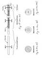
- FIGS. 1A-1Dillustrates a typical construction of a prior art steerable guide wire, such as those commonly used in coronary interventions.
- the guide wiregenerally includes three portions, a proximal portion, a mid-portion, and a distal tip portion.
- There are two main components in steerable guide wiresa core wire that extends from a proximal end to a distal end, and a coil which extends over the mid-portion and tip portion of the guide wire.
- Lubricious coatingssuch as PTFE and/or hydrophilic or hydrophobic materials may also be present over some or all portions of the guide wire.
- the core wire component of the guide wireis typically fabricated of high tensile strength stainless steel wire, however other materials are also used, such as NITINOL, MP35N, or ELGILOY.
- the guide wireis relatively stiff in the proximal portion and becomes increasingly more flexible towards the distal end.
- the proximal portionis typically of the original wire diameter (e.g., 0.014 inches for a coronary guide wire).
- the mid-portionis made more flexible by grinding down the diameter of the core wire to one or more smaller dimensions (e.g., 0.005 to 0.010 inches).
- the distal tip portion of the guide wireis made even more flexible by further grinding of the core wire to a smaller dimension (e.g., 0.002 to 0.003 inches). While grinding the core wire to these smaller diameters does impart flexibility to the core wire, it is typically still not flexible enough for the tip portion to be atraumatic to the vasculature. Therefore the dimension of the core wire in the tip region is reduced even further by stamping or rolling the round wire into a flat ribbon configuration.
- the ribbon structureis illustrated in FIGS. 2A and 2B , as well as Section C-C in FIG. 1D . As seen in FIGS. 1D , 2 A, and 2 B, the ribbon is formed integrally with the core wire. However, in an alternative method of manufacture, it is also known to attach a separately formed piece of ribbon to a distal end of the mid portion of the core wire.
- the high degree of flexibility achieved by the ribbon configurationcould theoretically be accomplished by grinding the core wire to a round dimension that gives the equivalent stiffness of the ribbon.
- the cross-sectional area of such a round wirewould be substantially less than the cross-sectional area of the ribbon configuration. Therefore the tensile integrity of the core wire would be significantly lowered.
- the dimensions of the ribbon structure of the tip portionis approximately 0.001 by 0.003 inches.
- Such dimensions in a high tensile strength stainless steel core wireyield a tip portion with a high degree of flexibility and a tensile strength of approximately 0.9 lbs, which is close to the minimum acceptable tensile strength integrity for the tip portion of the guide wire.
- the prior art guide wire described abovehas a tip portion with good flexibility and acceptable tensile integrity, it does have compromised steerability as a result of the ribbon structure in the tip portion.
- the ribbon portionis typically about 2 cm in length. Any time the tip portion is positioned in a tortuous region of the vasculature (such as illustrated in FIG. 5 ), the ribbon will naturally bend only in the direction perpendicular to the ribbon's widest dimension (e.g., out of the plane of the page as shown in FIG. 2B ). For a ribbon structure, there are thus only two stable bending directions 180 degrees apart from each other.
- the tipwill resist rotating. Torque or energy will be stored in the ribbon in the form of a twist in the proximal region of the ribbon, as well as in the core wire extending proximally from the ribbon. Continued rotation of the proximal end of the guide wire will cause enough torque to build up such that the tip portion will suddenly rotate or “whip” to its next stable orientation. This orientation is 180 degrees from the previous orientation. Therefore, the ability to rotate the tip to orientations between 0 and 180 degrees is hampered. Similarly, if the guide wire is further rotated, the tip portion will again resist rotating until enough torque is built up and then the tip will suddenly rotate an addition 180 degrees.
- a steerable guide wirethat exhibits controllable steering of the tip even in anatomically challenging vasculature.
- Such a steerable guide wireshould have excellent steerability, tip flexibility, as well as tensile integrity.
- a guide wirethat is able to be rotated at the proximal end without any “whipping” of the distal tip.
- the present inventionprovides for a steerable guide wire that dramatically improves steerability without compromising tensile integrity or flexibility.
- a steerable guide wirein one aspect of the invention, includes a core wire having a proximal end and a distal end.
- a multi-filament bundleis affixed to the distal end of the core wire.
- An outer coilsurrounds at least a portion of the core wire and the multi-filament bundle.
- a proximal end of the multi-filament bundleis secured to a distal end of the coil.
- a guide wirein another aspect of the invention, includes a proximal portion including a core wire and a distal portion that includes a multi-filament bundle coupled to the distal end of the core wire.
- a guide wirein yet another aspect of the invention, includes a core wire having a proximal end and a distal end and a multi-filament bundle disposed at the distal end of the core wire, the multi-filament bundle including a plurality of filaments that are twisted in a common direction.
- a coilsurrounds at least a portion of the core wire and the multi-filament bundle.
- the multi-filament bundleincludes a central filament and a plurality of outer filaments.
- the multi-filament bundleincludes a central filament surrounded by a plurality of filament bundles. Each bundle includes a plurality of individual filaments.
- the multi-filament bundlemay be made of a central filament formed from a first material and a plurality of outer filaments formed from a second material.
- the central filamentmay be formed from a radiopaque material.
- FIG. 1Ais a side view of a guide wire according to the prior art.
- FIG. 1Afurther includes partial cross-sectional views illustrating the core wire portion under the outer coil.
- FIG. 1Bis a cross-sectional view of the proximal shaft portion of the guide wire taken along the line A-A of FIG. 1A .
- FIG. 1Cis a cross-sectional view of the mid-shaft portion of the guide wire taken along the line B-B of FIG. 1A .
- FIG. 1Dis a cross-sectional view of the distal tip portion of the guide wire taken along the line C-C of FIG. 1A .
- FIG. 2Ais a magnified side view of the dashed region of FIG. 1A .
- FIG. 2Bis a magnified top view of the dashed region of FIG. 1A .
- the top viewis generally perpendicular to the view shown in FIG. 2A .
- FIG. 2Billustrates the width of the ribbon structure according to the prior art.
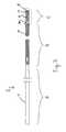
- FIG. 3illustrates side a view of a guide wire according to one aspect of the invention.
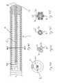
- FIG. 4Aillustrates a magnified view of the distal tip portion of a guide wire according to one aspect of the invention.
- FIG. 4Billustrates a cross-sectional view of the distal tip portion of the guide wire taken along the line D-D in FIG. 4A according to one embodiment of the invention.
- FIG. 4Cillustrates a cross-sectional view of the distal tip portion of the guide wire taken along the line D-D in FIG. 4A according to another embodiment of the invention.
- FIG. 4Dillustrates a cross-sectional view of the distal tip portion of the guide wire taken along the line D-D in FIG. 4A according to another embodiment of the invention.
- FIG. 4Eillustrates a cross-sectional view of the distal tip portion of the guide wire taken along the line D-D in FIG. 4A according to another embodiment of the invention.
- FIG. 5illustrates a guide wire according to the present invention being advanced in a side branch of a vessel.
- FIG. 6illustrates a magnified view of the distal tip portion of a guide wire according to another aspect of the invention.
- FIG. 3illustrates a guide wire 2 according to one preferred aspect of the invention.
- the guide wire 2generally includes a proximal portion A, a mid portion B, and a distal tip portion C.
- the guide wire 2includes a solid core wire 4 that traverses the proximal and mid portions A, B and terminates in or near the distal tip portion C.
- the diameter of the core wire 4is reduced in the mid portion B of guide wire 2 to increase its flexibility.
- the distal end 4 a of the core wire 4is coupled to a multi-filament bundle 6 .
- the multi-filament bundle 6projects distally from the distal end 4 a of the core wire 4 and terminates in a distal tip portion 8 .
- the guide wire 2further includes a coil 10 that is wrapped or wound around a portion of the exterior of the core wire 4 and multi-filament bundle 6 .
- the coil 10begins in the mid portion B of the guide wire 2 and terminates at the distal tip 8 .
- the distal tip 8may include an end cap 12 such as a weld, braze, solder, adhesive, or the like to secure the distal most end of the multi-filament bundle 6 .
- the proximal and mid portions A, B of the guide wire 2may be formed of any material suitable for guide wires including, but not limited to, 304 stainless steel, 316 stainless steel, NITINOL, MP35N, or ELGILOY. Fabrication of the proximal and mid portions A, B of the guide wire 2 may make use of methods and techniques such as centerless grinding and/or chemical etching.
- the outer coil 10may be formed of stainless steel or other suitable materials. In one aspect of the invention, the entire outer coil 10 or one or more sections thereof can incorporate radiopaque materials such as platinum/iridium, gold, or the like.
- a polymer jacketpreferably loaded with radiopaque material such as barium sulfate or bismuth subcarbonate may be secured over all or portions of the core wire 4 and multi-filament bundle 6 .
- the guide wire 2may include one or more lubricious coatings (not shown) that are applied to the guide wire 2 or portions thereof.
- the core wire 4terminates at or near the distal end of the mid portion B of the guide wire 2 .
- a multi-filament bundle 6is attached or otherwise mechanically connected to the distal end of the core wire 4 .
- the multi-filament bundle 6is shown as a distinct assembly from the core wire 4 .
- the multi-filament bundle 6extends to the distal tip portion 8 of the guide wire 2 .
- the multi-filament bundle 6includes a plurality of individual filaments 6 a that are arranged in a bundle, for example, as shown in FIG. 4A .
- the multi-filament bundle 6may be formed of two or more individual wire filaments of high tensile strength material such as 304 stainless steel or 316 stainless steel or other suitable materials.
- the multi-filament bundle 6may include stranded wire cable formed of seven wire filaments 6 a as depicted in FIG. 4B .
- FIG. 4Ashows a proximal end portion of the multi-filament bundle 6 extending proximal of a distal end surface of the core wire 4 .
- the multi-filament bundle 6may be formed from three filaments 6 a (e.g., wire filaments) as is depicted in FIG. 4C .
- a stranded wire cable comprising three or seven wire filaments 6 a of the same diametermay be preferred as it is generally more structurally stable than stranded wire bundles of other numbers of wire filaments.
- the present guide wire 2contemplates using a multi-filament bundle 6 of any number of filaments 6 a greater than two.
- the multi-filament bundle 6may be formed from a multi-filament inner core surrounded by a plurality of outer filaments.
- the multi-filament bundle 6includes a seven filament 6 a stranded wire cable of high tensile strength stainless steel.
- the length of the multi-filament bundle 6is preferably between 1 and 4 cm and most preferably about 2 cm although other lengths are also contemplated by the scope of the present invention.
- the filaments 6 aare preferably about 0.0005 inch to 0.0015 inch diameter and most preferably about 0.0008 to 0.0010 inch diameter.
- FIGS. 4A and 4Billustrate multi-filament bundle 6 in the form of a stranded wire bundle that is arranged with a central filament 6 a surrounded by six outer filaments 6 a all twisted in a common direction.
- the multi-filament bundle 6is formed from three filaments 6 a as is depicted in FIG. 4C .
- the wire filaments 6 aare preferably somewhat larger in diameter.
- FIG. 4Dillustrates a further embodiment wherein the central filament 6 a is of a different dimension (i.e., diameter) than the outer filaments 6 a ′.
- the multi-filament bundle 6includes one or more filament bundles 6 b .
- a central filament 6 ais surrounded by six filament bundles 6 b .
- Each filament bundle 6 bis formed from a plurality of filaments 6 a.
- each of the multi-filament bundle 6 arrangements depicted abovecan be tailored to have particular characteristics regarding flexibility, tensile strength, torsional stiffness, and tip formability (e.g., the ability to form a “J” bend such as that shown in FIG. 5 ).
- the arrangements depictedmay incorporate one or more filaments 6 a that are formed from different materials or have different properties than the other filament(s).
- the central filament 6 amay be fabricated of a radiopaque material such as platinum, while the outer filaments may be constructed of high tensile strength stainless steel.
- the central filament 6 acould be fabricated of a more ductile material such as annealed or low tensile strength stainless steel and the outer filaments 6 a ′ of high tensile strength stainless steel. This particular configuration would allow for the tip portion C to be highly formable yet retain high tensile strength due to the high tensile strength of the outer filaments 6 a′.
- the configuration depicted in FIGS. 4D and 4Emay utilize high strength polymeric materials for one or more of the filaments 6 a or filament bundles 6 b .
- the central filament 6 acould be formed of stainless steel and the outer filament bundles could be formed of a high strength polymer such as polyester, nylon, PTFE, or UHMWPE (Ultra High Molecular Weight Poly Ethylene) such as SPECTRA.
- the polymer bundles 6 bcould be twisted around the central filament 6 a or, alternatively, they could be arranged in a braided configuration around central filament 6 a.
- FIGS. 4B and 4Dcould have the outer filaments 6 a ′ arranged as a braid (as shown in FIG. 6 ).
- one or more of the outer filaments 6 a ′could be wound in a direction opposite that of the other outer filaments 6 a ′ (e.g., counter-wound filaments).
- the outer filaments 6 aare in a braided configuration, there may be no central filament 6 a as is shown in FIG. 6 .
- the multi-filament bundle 6is rotationally stable, i.e., it does not have a preferred bending direction as does the prior art ribbon configuration. Therefore, if multi-filament bundle 6 is placed in a tortuous anatomy such as that depicted in FIG. 5 , the guide wire 2 will permit the distal tip 8 of the guide wire 2 to be oriented in any direction in a controllable fashion.
- the distal tip 8 of the guide wire 2will advantageously have a 1:1 response or a substantially 1:1 torque response.
- the guide wire 2eliminates the “whipping” motion that heretofore accompanied guide wires that utilized a ribbon structure at the distal tip.
- the attachment of multi-filament bundle 6 to the distal end 4 a of the core wire 4can be accomplished by any suitable means such as soldering, brazing, welding, or adhesive bonding.
- the distal end of the multi-filament bundle 6can be attached to the distal end of the outer coil 10 by suitable means including soldering, brazing, welding, or adhesive bonding.
- the multi-filament bundle 6is more flexible than a solid structure of equivalent diameter, yet retains approximately the same tensile strength as a solid structure of the same equivalent diameter. This characteristic advantageously allows for a multi-filament bundle 6 to have both high flexibility and high tensile strength.
- the multi-filament bundle 6is rotationally stable. Consequently, a guide wire 2 making use of the multi-filament bundle 6 in the distal tip portion C can be highly flexible, have high tensile integrity, and be highly steerable, even in tortuous vasculature.
- the distal tip 8 portion of the guide wire 2has substantially uniform stiffness in all radial directions.
Landscapes
- Health & Medical Sciences (AREA)
- Life Sciences & Earth Sciences (AREA)
- Biophysics (AREA)
- Pulmonology (AREA)
- Engineering & Computer Science (AREA)
- Anesthesiology (AREA)
- Biomedical Technology (AREA)
- Heart & Thoracic Surgery (AREA)
- Hematology (AREA)
- Animal Behavior & Ethology (AREA)
- General Health & Medical Sciences (AREA)
- Public Health (AREA)
- Veterinary Medicine (AREA)
- Media Introduction/Drainage Providing Device (AREA)
Abstract
Description
Claims (5)
Priority Applications (3)
| Application Number | Priority Date | Filing Date | Title |
|---|---|---|---|
| US11/176,485US8267872B2 (en) | 2005-07-07 | 2005-07-07 | Steerable guide wire with torsionally stable tip |
| US11/652,234US20070185415A1 (en) | 2005-07-07 | 2007-01-10 | Steerable guide wire with torsionally stable tip |
| US12/484,910US8353850B2 (en) | 2005-07-07 | 2009-06-15 | Steerable guide wire with torsionally stable tip |
Applications Claiming Priority (1)
| Application Number | Priority Date | Filing Date | Title |
|---|---|---|---|
| US11/176,485US8267872B2 (en) | 2005-07-07 | 2005-07-07 | Steerable guide wire with torsionally stable tip |
Related Child Applications (1)
| Application Number | Title | Priority Date | Filing Date |
|---|---|---|---|
| US11/652,234Continuation-In-PartUS20070185415A1 (en) | 2005-07-07 | 2007-01-10 | Steerable guide wire with torsionally stable tip |
Publications (2)
| Publication Number | Publication Date |
|---|---|
| US20070010762A1 US20070010762A1 (en) | 2007-01-11 |
| US8267872B2true US8267872B2 (en) | 2012-09-18 |
Family
ID=37619154
Family Applications (1)
| Application Number | Title | Priority Date | Filing Date |
|---|---|---|---|
| US11/176,485Expired - Fee RelatedUS8267872B2 (en) | 2005-07-07 | 2005-07-07 | Steerable guide wire with torsionally stable tip |
Country Status (1)
| Country | Link |
|---|---|
| US (1) | US8267872B2 (en) |
Cited By (8)
| Publication number | Priority date | Publication date | Assignee | Title |
|---|---|---|---|---|
| US20120179141A1 (en)* | 2009-06-16 | 2012-07-12 | Asahi Intecc Co., Ltd. | Medical guidewire |
| US20120197159A1 (en)* | 2011-01-28 | 2012-08-02 | Asahi Intecc Co., Ltd. | Guidewire |
| US20130006149A1 (en)* | 2011-06-29 | 2013-01-03 | Abbott Cardiovascular Systems | Guide Wire Device Including a Solderable Linear Elastic Nickel-Titanium Distal End Section and Methods Of Preparation Therefor |
| US10682497B2 (en) | 2013-12-20 | 2020-06-16 | Microvention, Inc. | Steerable guidewire system |
| US10763653B2 (en)* | 2018-04-04 | 2020-09-01 | Yazaki Corporation | Branch circuit body and electric wire branching method |
| US11779477B2 (en) | 2010-11-17 | 2023-10-10 | Abbott Cardiovascular Systems, Inc. | Radiopaque intraluminal stents |
| US12017012B2 (en)* | 2019-02-05 | 2024-06-25 | Bard Access Systems, Inc. | Apparatus and methods to modulate stylet stiffness profile |
| US12151049B2 (en) | 2019-10-14 | 2024-11-26 | Abbott Cardiovascular Systems, Inc. | Methods for manufacturing radiopaque intraluminal stents comprising cobalt-based alloys with supersaturated tungsten content |
Families Citing this family (22)
| Publication number | Priority date | Publication date | Assignee | Title |
|---|---|---|---|---|
| US7951091B2 (en)* | 2003-07-31 | 2011-05-31 | Tyco Healthcare Group Lp | Guide wire with stranded tip |
| US8414633B2 (en)* | 2005-07-21 | 2013-04-09 | Cook Medical Technologies Llc | Stent delivery system with a retention wire |
| JP2008161491A (en)* | 2006-12-28 | 2008-07-17 | Asahi Intecc Co Ltd | Medical guidewire |
| US20080294145A1 (en)* | 2007-05-25 | 2008-11-27 | Galt Medical Corporation | Catheter hub with flushable lumen and guidewire |
| JP5067845B2 (en)* | 2007-06-22 | 2012-11-07 | 朝日インテック株式会社 | Medical guidewire |
| US9061117B2 (en) | 2011-04-08 | 2015-06-23 | John R. Roberts | Catheter systems and methods of use |
| US9061088B2 (en)* | 2012-02-02 | 2015-06-23 | Abbott Cardiovascular Systems, Inc. | Guide wire core wire made from a substantially titanium-free alloy for enhanced guide wire steering response |
| DE102012010687B4 (en)* | 2012-05-30 | 2021-08-19 | ADMEDES GmbH | A method for producing a body implant, an assembly comprising a guide wire and a body implant, and a medical instrument |
| US9636485B2 (en) | 2013-01-17 | 2017-05-02 | Abbott Cardiovascular Systems, Inc. | Methods for counteracting rebounding effects during solid state resistance welding of dissimilar materials |
| US20140261407A1 (en) | 2013-03-14 | 2014-09-18 | Patient Centered Medical Incorporated | Aspiration catheters, systems, and methods |
| KR102308478B1 (en)* | 2013-03-15 | 2021-10-07 | 페이션트 센터드 메디칼 인코포레이티드 | Aspiration catheters, systems, and methods |
| JP5976983B1 (en) | 2013-07-01 | 2016-08-24 | ズーリック・メディカル・コーポレイションZurich Medical Corporation | Apparatus and method for intravascular measurement |
| US10835183B2 (en)* | 2013-07-01 | 2020-11-17 | Zurich Medical Corporation | Apparatus and method for intravascular measurements |
| JP2015137428A (en)* | 2014-01-20 | 2015-07-30 | 朝日インテック株式会社 | Twisted wire and guide wire using the same |
| JP2015159865A (en)* | 2014-02-26 | 2015-09-07 | 朝日インテック株式会社 | Guide wire |
| JP6482766B2 (en)* | 2014-03-19 | 2019-03-13 | 朝日インテック株式会社 | Guide wire |
| JP2015208362A (en)* | 2014-04-24 | 2015-11-24 | 朝日インテック株式会社 | Guide wire |
| US11090465B2 (en)* | 2014-08-21 | 2021-08-17 | Boston Scientific Scimed, Inc. | Medical device with support member |
| JP6348455B2 (en)* | 2015-06-03 | 2018-06-27 | 株式会社ハイレックスコーポレーション | Guide wire |
| AU2016282495B2 (en)* | 2015-06-23 | 2021-04-08 | Zurich Medical Corporation | Apparatus and method for intravascular measurements |
| JP2017070803A (en)* | 2016-12-15 | 2017-04-13 | 朝日インテック株式会社 | Guide wire |
| KR20200024287A (en)* | 2017-07-19 | 2020-03-06 | 아사히 인텍크 가부시키가이샤 | Guide wire |
Citations (58)
| Publication number | Priority date | Publication date | Assignee | Title |
|---|---|---|---|---|
| US3612058A (en)* | 1968-04-17 | 1971-10-12 | Electro Catheter Corp | Catheter stylets |
| US4579127A (en)* | 1983-08-02 | 1986-04-01 | Intermedicat Gmbh | Mandrel for hose type catheters and body probes |
| US4682607A (en) | 1985-12-02 | 1987-07-28 | Vlv Associates | Wire guide |
| US4763647A (en) | 1987-01-06 | 1988-08-16 | C. R. Bard, Inc. | Dual coil steerable guidewire |
| US4867173A (en)* | 1986-06-30 | 1989-09-19 | Meadox Surgimed A/S | Steerable guidewire |
| US4932419A (en)* | 1988-03-21 | 1990-06-12 | Boston Scientific Corporation | Multi-filar, cross-wound coil for medical devices |
| US4967753A (en)* | 1987-04-10 | 1990-11-06 | Cardiometrics, Inc. | Apparatus, system and method for measuring spatial average velocity and/or volumetric flow of blood in a vessel |
| US5007434A (en) | 1989-02-07 | 1991-04-16 | Advanced Cardiovascular Systems, Inc. | Catheter tip attitude controlling guide wire |
| US5063935A (en) | 1989-04-27 | 1991-11-12 | C. R. Bard, Inc. | Catheter guidewire with varying radiopacity |
| US5144959A (en) | 1989-08-15 | 1992-09-08 | C. R. Bard, Inc. | Catheter guidewire with varying radiopacity |
| US5203772A (en)* | 1989-01-09 | 1993-04-20 | Pilot Cardiovascular Systems, Inc. | Steerable medical device |
| US5228453A (en) | 1991-05-07 | 1993-07-20 | Target Therapeutics, Inc. | Catheter guide wire |
| US5299580A (en) | 1992-10-09 | 1994-04-05 | Scimed Life Systems, Inc. | Guidewire with safety ribbon with substantially axially symmetric flexibility |
| US5377690A (en)* | 1993-02-09 | 1995-01-03 | C. R. Bard, Inc. | Guidewire with round forming wire |
| US5379779A (en)* | 1993-08-16 | 1995-01-10 | Boston Scientific Corporation | Zebra exchange guidewire |
| US5542434A (en)* | 1994-10-28 | 1996-08-06 | Intelliwire Inc. | Guide wire with deflectable tip and method |
| US5769796A (en) | 1993-05-11 | 1998-06-23 | Target Therapeutics, Inc. | Super-elastic composite guidewire |
| US5772609A (en) | 1993-05-11 | 1998-06-30 | Target Therapeutics, Inc. | Guidewire with variable flexibility due to polymeric coatings |
| US5827201A (en) | 1996-07-26 | 1998-10-27 | Target Therapeutics, Inc. | Micro-braided guidewire |
| US5833631A (en) | 1996-06-28 | 1998-11-10 | Target Therapeutics, Inc. | Fiber tip guidewire |
| US5902254A (en) | 1996-07-29 | 1999-05-11 | The Nemours Foundation | Cathether guidewire |
| US5938623A (en) | 1994-10-28 | 1999-08-17 | Intella Interventional Systems | Guide wire with adjustable stiffness |
| US5951496A (en) | 1996-05-03 | 1999-09-14 | Schneider (Europe) Gmbh | Guide wire and method of producing a guide wire |
| US6017319A (en) | 1996-05-24 | 2000-01-25 | Precision Vascular Systems, Inc. | Hybrid tubular guide wire for catheters |
| US6019736A (en) | 1995-11-06 | 2000-02-01 | Francisco J. Avellanet | Guidewire for catheter |
| US6139510A (en) | 1994-05-11 | 2000-10-31 | Target Therapeutics Inc. | Super elastic alloy guidewire |
| US6159165A (en) | 1997-12-05 | 2000-12-12 | Micrus Corporation | Three dimensional spherical micro-coils manufactured from radiopaque nickel-titanium microstrand |
| US6168570B1 (en)* | 1997-12-05 | 2001-01-02 | Micrus Corporation | Micro-strand cable with enhanced radiopacity |
| US6183420B1 (en) | 1997-06-20 | 2001-02-06 | Medtronic Ave, Inc. | Variable stiffness angioplasty guide wire |
| US6190353B1 (en) | 1995-10-13 | 2001-02-20 | Transvascular, Inc. | Methods and apparatus for bypassing arterial obstructions and/or performing other transvascular procedures |
| US6344029B1 (en) | 1999-06-30 | 2002-02-05 | Advanced Cardiovascular Systems, Inc. | Catheter with enhanced flexibility |
| US6383146B1 (en) | 1999-03-29 | 2002-05-07 | Cook Incorporated | Guidewire |
| US6428489B1 (en) | 1995-12-07 | 2002-08-06 | Precision Vascular Systems, Inc. | Guidewire system |
| US6440088B1 (en) | 1996-05-24 | 2002-08-27 | Precision Vascular Systems, Inc. | Hybrid catheter guide wire apparatus and method |
| US6488637B1 (en)* | 1996-04-30 | 2002-12-03 | Target Therapeutics, Inc. | Composite endovascular guidewire |
| US20030069521A1 (en) | 2001-10-05 | 2003-04-10 | Brian Reynolds | Composite guidewire |
| US6579246B2 (en) | 1999-12-22 | 2003-06-17 | Sarcos, Lc | Coronary guidewire system |
| US6579278B1 (en) | 2000-05-05 | 2003-06-17 | Scimed Life Systems, Inc. | Bi-directional steerable catheter with asymmetric fulcrum |
| US20030181827A1 (en) | 2002-03-22 | 2003-09-25 | Hikmat Hojeibane | Guidewire with deflectable tip |
| US20030181828A1 (en) | 2002-01-28 | 2003-09-25 | Katsuharu Fujimoto | Guide wire |
| US6669652B2 (en) | 2000-12-21 | 2003-12-30 | Advanced Cardiovascular Systems, Inc. | Guidewire with tapered distal coil |
| US6679853B1 (en) | 1998-06-17 | 2004-01-20 | Advanced Cardiovascular Systems, Inc. | Composite radiopaque intracorporeal product |
| US20040039304A1 (en) | 2002-08-23 | 2004-02-26 | Connors John J. | Wire guide |
| US6706055B2 (en)* | 2001-04-03 | 2004-03-16 | Medtronic Ave Inc. | Guidewire apparatus for temporary distal embolic protection |
| US20040054301A1 (en) | 2002-09-18 | 2004-03-18 | Scimed Life Systems, Inc. | Flexible composite guidewire for intravascular catheter |
| US20040102719A1 (en) | 2002-11-22 | 2004-05-27 | Velocimed, L.L.C. | Guide wire control catheters for crossing occlusions and related methods of use |
| US20040111044A1 (en)* | 2002-07-25 | 2004-06-10 | Precision Vascular Systems, Inc. | Medical device for navigation through anatomy and method of making same |
| US20040143265A1 (en) | 2002-10-30 | 2004-07-22 | Landry Michael E. | Spinal stabilization systems and methods using minimally invasive surgical procedures |
| US20040193073A1 (en) | 2003-03-31 | 2004-09-30 | Demello Richard M. | Composite guidewire with a linear elastic distal portion |
| US20040260206A1 (en) | 2003-03-18 | 2004-12-23 | Terumo Kabushiki Kaisha | Guide wire and method of manufacturing the guide wire |
| US20050027212A1 (en) | 2003-07-31 | 2005-02-03 | Segner Garland L. | Guide wire with stranded tip |
| US20050038359A1 (en) | 2003-07-17 | 2005-02-17 | Terumo Kabushiki Kaisha | Guide wire |
| WO2005027212A1 (en) | 2003-09-10 | 2005-03-24 | Hamamatsu Photonics K.K. | Semiconductor substrate cutting method |
| US20050080356A1 (en) | 2003-10-14 | 2005-04-14 | Steven Dapolito | Steerable distal protection guidewire and methods of use |
| WO2005092422A1 (en) | 2004-03-26 | 2005-10-06 | Brivant Research & Development Limited | A guide wire for use in re-canalising a vascular occlusion in a human or animal subject |
| US6955657B1 (en)* | 2001-12-31 | 2005-10-18 | Advanced Cardiovascular Systems, Inc. | Intra-ventricular substance delivery catheter system |
| US20060064036A1 (en) | 2004-09-21 | 2006-03-23 | Cook Incorporated | Variable flexibility wire guide |
| US7618379B2 (en) | 2001-10-05 | 2009-11-17 | Boston Scientific Scimed, Inc. | Composite guidewire |
Family Cites Families (1)
| Publication number | Priority date | Publication date | Assignee | Title |
|---|---|---|---|---|
| US6312058B1 (en)* | 1999-04-13 | 2001-11-06 | Raymond L. Lupyrypa | Centering the rim of a wheel on its supporting hub |
- 2005
- 2005-07-07USUS11/176,485patent/US8267872B2/ennot_activeExpired - Fee Related
Patent Citations (59)
| Publication number | Priority date | Publication date | Assignee | Title |
|---|---|---|---|---|
| US3612058A (en)* | 1968-04-17 | 1971-10-12 | Electro Catheter Corp | Catheter stylets |
| US4579127A (en)* | 1983-08-02 | 1986-04-01 | Intermedicat Gmbh | Mandrel for hose type catheters and body probes |
| US4682607A (en) | 1985-12-02 | 1987-07-28 | Vlv Associates | Wire guide |
| US4867173A (en)* | 1986-06-30 | 1989-09-19 | Meadox Surgimed A/S | Steerable guidewire |
| US4763647A (en) | 1987-01-06 | 1988-08-16 | C. R. Bard, Inc. | Dual coil steerable guidewire |
| US4967753A (en)* | 1987-04-10 | 1990-11-06 | Cardiometrics, Inc. | Apparatus, system and method for measuring spatial average velocity and/or volumetric flow of blood in a vessel |
| US4932419A (en)* | 1988-03-21 | 1990-06-12 | Boston Scientific Corporation | Multi-filar, cross-wound coil for medical devices |
| US5203772A (en)* | 1989-01-09 | 1993-04-20 | Pilot Cardiovascular Systems, Inc. | Steerable medical device |
| US5007434A (en) | 1989-02-07 | 1991-04-16 | Advanced Cardiovascular Systems, Inc. | Catheter tip attitude controlling guide wire |
| US5063935A (en) | 1989-04-27 | 1991-11-12 | C. R. Bard, Inc. | Catheter guidewire with varying radiopacity |
| US5144959A (en) | 1989-08-15 | 1992-09-08 | C. R. Bard, Inc. | Catheter guidewire with varying radiopacity |
| US5228453A (en) | 1991-05-07 | 1993-07-20 | Target Therapeutics, Inc. | Catheter guide wire |
| US5299580A (en) | 1992-10-09 | 1994-04-05 | Scimed Life Systems, Inc. | Guidewire with safety ribbon with substantially axially symmetric flexibility |
| US5377690A (en)* | 1993-02-09 | 1995-01-03 | C. R. Bard, Inc. | Guidewire with round forming wire |
| US5769796A (en) | 1993-05-11 | 1998-06-23 | Target Therapeutics, Inc. | Super-elastic composite guidewire |
| US5772609A (en) | 1993-05-11 | 1998-06-30 | Target Therapeutics, Inc. | Guidewire with variable flexibility due to polymeric coatings |
| US5379779A (en)* | 1993-08-16 | 1995-01-10 | Boston Scientific Corporation | Zebra exchange guidewire |
| US6139510A (en) | 1994-05-11 | 2000-10-31 | Target Therapeutics Inc. | Super elastic alloy guidewire |
| US5938623A (en) | 1994-10-28 | 1999-08-17 | Intella Interventional Systems | Guide wire with adjustable stiffness |
| US5542434A (en)* | 1994-10-28 | 1996-08-06 | Intelliwire Inc. | Guide wire with deflectable tip and method |
| US6190353B1 (en) | 1995-10-13 | 2001-02-20 | Transvascular, Inc. | Methods and apparatus for bypassing arterial obstructions and/or performing other transvascular procedures |
| US6019736A (en) | 1995-11-06 | 2000-02-01 | Francisco J. Avellanet | Guidewire for catheter |
| US6428489B1 (en) | 1995-12-07 | 2002-08-06 | Precision Vascular Systems, Inc. | Guidewire system |
| US6488637B1 (en)* | 1996-04-30 | 2002-12-03 | Target Therapeutics, Inc. | Composite endovascular guidewire |
| US5951496A (en) | 1996-05-03 | 1999-09-14 | Schneider (Europe) Gmbh | Guide wire and method of producing a guide wire |
| US6017319A (en) | 1996-05-24 | 2000-01-25 | Precision Vascular Systems, Inc. | Hybrid tubular guide wire for catheters |
| US6440088B1 (en) | 1996-05-24 | 2002-08-27 | Precision Vascular Systems, Inc. | Hybrid catheter guide wire apparatus and method |
| US5833631A (en) | 1996-06-28 | 1998-11-10 | Target Therapeutics, Inc. | Fiber tip guidewire |
| US5827201A (en) | 1996-07-26 | 1998-10-27 | Target Therapeutics, Inc. | Micro-braided guidewire |
| US5902254A (en) | 1996-07-29 | 1999-05-11 | The Nemours Foundation | Cathether guidewire |
| US6183420B1 (en) | 1997-06-20 | 2001-02-06 | Medtronic Ave, Inc. | Variable stiffness angioplasty guide wire |
| US6168570B1 (en)* | 1997-12-05 | 2001-01-02 | Micrus Corporation | Micro-strand cable with enhanced radiopacity |
| US6159165A (en) | 1997-12-05 | 2000-12-12 | Micrus Corporation | Three dimensional spherical micro-coils manufactured from radiopaque nickel-titanium microstrand |
| US6679853B1 (en) | 1998-06-17 | 2004-01-20 | Advanced Cardiovascular Systems, Inc. | Composite radiopaque intracorporeal product |
| US6383146B1 (en) | 1999-03-29 | 2002-05-07 | Cook Incorporated | Guidewire |
| US6344029B1 (en) | 1999-06-30 | 2002-02-05 | Advanced Cardiovascular Systems, Inc. | Catheter with enhanced flexibility |
| US6579246B2 (en) | 1999-12-22 | 2003-06-17 | Sarcos, Lc | Coronary guidewire system |
| US6579278B1 (en) | 2000-05-05 | 2003-06-17 | Scimed Life Systems, Inc. | Bi-directional steerable catheter with asymmetric fulcrum |
| US6669652B2 (en) | 2000-12-21 | 2003-12-30 | Advanced Cardiovascular Systems, Inc. | Guidewire with tapered distal coil |
| US6706055B2 (en)* | 2001-04-03 | 2004-03-16 | Medtronic Ave Inc. | Guidewire apparatus for temporary distal embolic protection |
| US20030069521A1 (en) | 2001-10-05 | 2003-04-10 | Brian Reynolds | Composite guidewire |
| US7618379B2 (en) | 2001-10-05 | 2009-11-17 | Boston Scientific Scimed, Inc. | Composite guidewire |
| US6955657B1 (en)* | 2001-12-31 | 2005-10-18 | Advanced Cardiovascular Systems, Inc. | Intra-ventricular substance delivery catheter system |
| US20030181828A1 (en) | 2002-01-28 | 2003-09-25 | Katsuharu Fujimoto | Guide wire |
| US20030181827A1 (en) | 2002-03-22 | 2003-09-25 | Hikmat Hojeibane | Guidewire with deflectable tip |
| US20040111044A1 (en)* | 2002-07-25 | 2004-06-10 | Precision Vascular Systems, Inc. | Medical device for navigation through anatomy and method of making same |
| US20040039304A1 (en) | 2002-08-23 | 2004-02-26 | Connors John J. | Wire guide |
| US20040054301A1 (en) | 2002-09-18 | 2004-03-18 | Scimed Life Systems, Inc. | Flexible composite guidewire for intravascular catheter |
| US20040143265A1 (en) | 2002-10-30 | 2004-07-22 | Landry Michael E. | Spinal stabilization systems and methods using minimally invasive surgical procedures |
| US20040102719A1 (en) | 2002-11-22 | 2004-05-27 | Velocimed, L.L.C. | Guide wire control catheters for crossing occlusions and related methods of use |
| US20040260206A1 (en) | 2003-03-18 | 2004-12-23 | Terumo Kabushiki Kaisha | Guide wire and method of manufacturing the guide wire |
| US20040193073A1 (en) | 2003-03-31 | 2004-09-30 | Demello Richard M. | Composite guidewire with a linear elastic distal portion |
| US20050038359A1 (en) | 2003-07-17 | 2005-02-17 | Terumo Kabushiki Kaisha | Guide wire |
| US20050027212A1 (en) | 2003-07-31 | 2005-02-03 | Segner Garland L. | Guide wire with stranded tip |
| WO2005016433A2 (en) | 2003-07-31 | 2005-02-24 | Ev3 Inc. | Guide wire with stranded tip |
| WO2005027212A1 (en) | 2003-09-10 | 2005-03-24 | Hamamatsu Photonics K.K. | Semiconductor substrate cutting method |
| US20050080356A1 (en) | 2003-10-14 | 2005-04-14 | Steven Dapolito | Steerable distal protection guidewire and methods of use |
| WO2005092422A1 (en) | 2004-03-26 | 2005-10-06 | Brivant Research & Development Limited | A guide wire for use in re-canalising a vascular occlusion in a human or animal subject |
| US20060064036A1 (en) | 2004-09-21 | 2006-03-23 | Cook Incorporated | Variable flexibility wire guide |
Cited By (15)
| Publication number | Priority date | Publication date | Assignee | Title |
|---|---|---|---|---|
| US9017268B2 (en)* | 2009-06-16 | 2015-04-28 | Asahi Intecc Co., Ltd. | Medical guidewire |
| US20120179141A1 (en)* | 2009-06-16 | 2012-07-12 | Asahi Intecc Co., Ltd. | Medical guidewire |
| US8956310B2 (en) | 2009-06-16 | 2015-02-17 | Asahi Intecc Co., Ltd. | Medical guidewire |
| US8961434B2 (en) | 2009-06-16 | 2015-02-24 | Asahi Intecc Co., Ltd. | Medical guidewire |
| US12150872B2 (en) | 2010-11-17 | 2024-11-26 | Abbott Cardiovascular Systems, Inc. | Radiopaque intraluminal stents |
| US11779477B2 (en) | 2010-11-17 | 2023-10-10 | Abbott Cardiovascular Systems, Inc. | Radiopaque intraluminal stents |
| US8758269B2 (en)* | 2011-01-28 | 2014-06-24 | Asahi Intecc Co., Ltd. | Guidewire |
| US20120197159A1 (en)* | 2011-01-28 | 2012-08-02 | Asahi Intecc Co., Ltd. | Guidewire |
| US9724494B2 (en)* | 2011-06-29 | 2017-08-08 | Abbott Cardiovascular Systems, Inc. | Guide wire device including a solderable linear elastic nickel-titanium distal end section and methods of preparation therefor |
| US20130006149A1 (en)* | 2011-06-29 | 2013-01-03 | Abbott Cardiovascular Systems | Guide Wire Device Including a Solderable Linear Elastic Nickel-Titanium Distal End Section and Methods Of Preparation Therefor |
| US11806488B2 (en) | 2011-06-29 | 2023-11-07 | Abbott Cardiovascular Systems, Inc. | Medical device including a solderable linear elastic nickel-titanium distal end section and methods of preparation therefor |
| US10682497B2 (en) | 2013-12-20 | 2020-06-16 | Microvention, Inc. | Steerable guidewire system |
| US10763653B2 (en)* | 2018-04-04 | 2020-09-01 | Yazaki Corporation | Branch circuit body and electric wire branching method |
| US12017012B2 (en)* | 2019-02-05 | 2024-06-25 | Bard Access Systems, Inc. | Apparatus and methods to modulate stylet stiffness profile |
| US12151049B2 (en) | 2019-10-14 | 2024-11-26 | Abbott Cardiovascular Systems, Inc. | Methods for manufacturing radiopaque intraluminal stents comprising cobalt-based alloys with supersaturated tungsten content |
Also Published As
| Publication number | Publication date |
|---|---|
| US20070010762A1 (en) | 2007-01-11 |
Similar Documents
| Publication | Publication Date | Title |
|---|---|---|
| US8267872B2 (en) | Steerable guide wire with torsionally stable tip | |
| US8353850B2 (en) | Steerable guide wire with torsionally stable tip | |
| US9737689B2 (en) | Guide wire with stranded tip | |
| EP1040843B1 (en) | A guidewire | |
| US6607496B1 (en) | Steerable stylet with enhanced torsional transfer strength | |
| CA2331000C (en) | High performance coil wire | |
| US6383146B1 (en) | Guidewire | |
| US8388572B2 (en) | Steerable catheter system | |
| US8257279B2 (en) | Medical device for navigation through anatomy and method of making same | |
| US20170087340A1 (en) | Guidewire With Torque Transmission Element | |
| US20020082524A1 (en) | Guidewire with tapered distal coil | |
| CN115414571A (en) | Guidewire device with shapeable polymer tip | |
| KR20220144804A (en) | Guide wire with an enlarged, micromachined distal portion | |
| US20100094258A1 (en) | Catheter | |
| WO1998018516A1 (en) | Vascular guidewire with axisymmetric steering and spring forming elements | |
| WO2008085167A1 (en) | Steerable guide wire with torsionally stable tip | |
| US20250186738A1 (en) | Medical devices with radiopaque coils | |
| KR20240146061A (en) | Guide wire device with core alignment mechanism |
Legal Events
| Date | Code | Title | Description |
|---|---|---|---|
| AS | Assignment | Owner name:INCUBEX, L.L.C., MINNESOTA Free format text:ASSIGNMENT OF ASSIGNORS INTEREST;ASSIGNORS:RESSEMANN, THOMAS V.;KEITH, PETER T.;REEL/FRAME:016534/0307 Effective date:20050907 | |
| AS | Assignment | Owner name:ST. JUDE MEDICAL, CARDIOLOGY DIVISION, INC., MINNE Free format text:ASSIGNMENT OF ASSIGNORS INTEREST;ASSIGNOR:INCUBEX, L.L.C.;REEL/FRAME:017618/0787 Effective date:20060313 | |
| ZAAA | Notice of allowance and fees due | Free format text:ORIGINAL CODE: NOA | |
| ZAAB | Notice of allowance mailed | Free format text:ORIGINAL CODE: MN/=. | |
| ZAAA | Notice of allowance and fees due | Free format text:ORIGINAL CODE: NOA | |
| STCF | Information on status: patent grant | Free format text:PATENTED CASE | |
| FPAY | Fee payment | Year of fee payment:4 | |
| MAFP | Maintenance fee payment | Free format text:PAYMENT OF MAINTENANCE FEE, 8TH YEAR, LARGE ENTITY (ORIGINAL EVENT CODE: M1552); ENTITY STATUS OF PATENT OWNER: LARGE ENTITY Year of fee payment:8 | |
| FEPP | Fee payment procedure | Free format text:MAINTENANCE FEE REMINDER MAILED (ORIGINAL EVENT CODE: REM.); ENTITY STATUS OF PATENT OWNER: LARGE ENTITY | |
| LAPS | Lapse for failure to pay maintenance fees | Free format text:PATENT EXPIRED FOR FAILURE TO PAY MAINTENANCE FEES (ORIGINAL EVENT CODE: EXP.); ENTITY STATUS OF PATENT OWNER: LARGE ENTITY | |
| STCH | Information on status: patent discontinuation | Free format text:PATENT EXPIRED DUE TO NONPAYMENT OF MAINTENANCE FEES UNDER 37 CFR 1.362 | |
| FP | Lapsed due to failure to pay maintenance fee | Effective date:20240918 |