US8266911B2 - Premixing device for low emission combustion process - Google Patents
Premixing device for low emission combustion processDownload PDFInfo
- Publication number
- US8266911B2 US8266911B2US11/273,212US27321205AUS8266911B2US 8266911 B2US8266911 B2US 8266911B2US 27321205 AUS27321205 AUS 27321205AUS 8266911 B2US8266911 B2US 8266911B2
- Authority
- US
- United States
- Prior art keywords
- fuel
- premixing device
- air
- combustor
- premixing
- Prior art date
- Legal status (The legal status is an assumption and is not a legal conclusion. Google has not performed a legal analysis and makes no representation as to the accuracy of the status listed.)
- Expired - Fee Related, expires
Links
- 238000002485combustion reactionMethods0.000titleclaimsdescription44
- 239000000446fuelSubstances0.000claimsabstractdescription201
- 238000002156mixingMethods0.000claimsabstractdescription57
- 239000003570airSubstances0.000claimsdescription112
- 239000007789gasSubstances0.000claimsdescription45
- 238000000034methodMethods0.000claimsdescription33
- VNWKTOKETHGBQD-UHFFFAOYSA-NmethaneChemical compoundCVNWKTOKETHGBQD-UHFFFAOYSA-N0.000claimsdescription26
- 230000000694effectsEffects0.000claimsdescription21
- 239000000203mixtureSubstances0.000claimsdescription21
- 239000007800oxidant agentSubstances0.000claimsdescription21
- UFHFLCQGNIYNRP-UHFFFAOYSA-NHydrogenChemical compound[H][H]UFHFLCQGNIYNRP-UHFFFAOYSA-N0.000claimsdescription20
- 239000001257hydrogenSubstances0.000claimsdescription20
- 229910052739hydrogenInorganic materials0.000claimsdescription20
- QVGXLLKOCUKJST-UHFFFAOYSA-Natomic oxygenChemical compound[O]QVGXLLKOCUKJST-UHFFFAOYSA-N0.000claimsdescription15
- 239000001301oxygenSubstances0.000claimsdescription15
- 229910052760oxygenInorganic materials0.000claimsdescription15
- 239000003345natural gasSubstances0.000claimsdescription13
- 238000011144upstream manufacturingMethods0.000claimsdescription10
- UGFAIRIUMAVXCW-UHFFFAOYSA-NCarbon monoxideChemical compound[O+]#[C-]UGFAIRIUMAVXCW-UHFFFAOYSA-N0.000claimsdescription7
- 229910002091carbon monoxideInorganic materials0.000claimsdescription7
- 239000012080ambient airSubstances0.000claimsdescription5
- 238000004891communicationMethods0.000claimsdescription5
- 239000003344environmental pollutantSubstances0.000claimsdescription4
- 150000002431hydrogenChemical class0.000claimsdescription4
- 238000002347injectionMethods0.000claimsdescription4
- 239000007924injectionSubstances0.000claimsdescription4
- 231100000719pollutantToxicity0.000claimsdescription4
- 230000006641stabilisationEffects0.000claimsdescription2
- 238000011105stabilizationMethods0.000claimsdescription2
- 230000008878couplingEffects0.000claims1
- 238000010168coupling processMethods0.000claims1
- 238000005859coupling reactionMethods0.000claims1
- 230000001939inductive effectEffects0.000claims1
- 239000001307heliumSubstances0.000description9
- 229910052734heliumInorganic materials0.000description9
- SWQJXJOGLNCZEY-UHFFFAOYSA-Nhelium atomChemical compound[He]SWQJXJOGLNCZEY-UHFFFAOYSA-N0.000description9
- 239000007788liquidSubstances0.000description6
- 230000015572biosynthetic processEffects0.000description5
- IJGRMHOSHXDMSA-UHFFFAOYSA-NAtomic nitrogenChemical compoundN#NIJGRMHOSHXDMSA-UHFFFAOYSA-N0.000description4
- CURLTUGMZLYLDI-UHFFFAOYSA-NCarbon dioxideChemical compoundO=C=OCURLTUGMZLYLDI-UHFFFAOYSA-N0.000description4
- 230000002708enhancing effectEffects0.000description4
- 239000012530fluidSubstances0.000description4
- 238000012545processingMethods0.000description4
- 238000000926separation methodMethods0.000description4
- 206010016754FlashbackDiseases0.000description3
- 238000006243chemical reactionMethods0.000description3
- 238000004401flow injection analysisMethods0.000description3
- 229930195733hydrocarbonNatural products0.000description3
- 150000002430hydrocarbonsChemical class0.000description3
- 230000009467reductionEffects0.000description3
- 238000012360testing methodMethods0.000description3
- 230000008901benefitEffects0.000description2
- 229910002092carbon dioxideInorganic materials0.000description2
- 239000001569carbon dioxideSubstances0.000description2
- 238000009792diffusion processMethods0.000description2
- 238000010438heat treatmentMethods0.000description2
- 238000012986modificationMethods0.000description2
- 230000004048modificationEffects0.000description2
- 229910052757nitrogenInorganic materials0.000description2
- 230000010355oscillationEffects0.000description2
- 230000008569processEffects0.000description2
- 239000000523sampleSubstances0.000description2
- 238000004088simulationMethods0.000description2
- 238000003786synthesis reactionMethods0.000description2
- -1biogasChemical compound0.000description1
- 238000006555catalytic reactionMethods0.000description1
- 230000008859changeEffects0.000description1
- 230000006835compressionEffects0.000description1
- 238000007906compressionMethods0.000description1
- 238000005336crackingMethods0.000description1
- 230000001066destructive effectEffects0.000description1
- 238000010790dilutionMethods0.000description1
- 239000012895dilutionSubstances0.000description1
- 239000002803fossil fuelSubstances0.000description1
- 238000002309gasificationMethods0.000description1
- 238000004519manufacturing processMethods0.000description1
- 238000005259measurementMethods0.000description1
- 230000007246mechanismEffects0.000description1
- 238000010248power generationMethods0.000description1
- 230000001737promoting effectEffects0.000description1
- 238000013341scale-upMethods0.000description1
- 230000000087stabilizing effectEffects0.000description1
- 238000012546transferMethods0.000description1
Images


Classifications
- F—MECHANICAL ENGINEERING; LIGHTING; HEATING; WEAPONS; BLASTING
- F23—COMBUSTION APPARATUS; COMBUSTION PROCESSES
- F23R—GENERATING COMBUSTION PRODUCTS OF HIGH PRESSURE OR HIGH VELOCITY, e.g. GAS-TURBINE COMBUSTION CHAMBERS
- F23R3/00—Continuous combustion chambers using liquid or gaseous fuel
- F23R3/28—Continuous combustion chambers using liquid or gaseous fuel characterised by the fuel supply
- F23R3/286—Continuous combustion chambers using liquid or gaseous fuel characterised by the fuel supply having fuel-air premixing devices
Definitions
- the inventionrelates generally to combustors, and more particularly to a premixing device for application in low emission combustion processes.
- combustorsare known and are in use.
- can type, can-annular or annular combustorsare employed in aeroderivative gas turbines for applications such as power generation, marine propulsion, gas compression, cogeneration, offshore platform power and so forth.
- the combustors for the gas turbinesare designed to minimize emissions such as NO x and carbon dioxide emissions.
- the reduction in emissions from the combustorsis achieved through premixed flames.
- the fuel and airare mixed prior to combustion and the mixing is achieved by employing cross-flow injection of fuel and subsequent dissipation and diffusion of the fuel in the air flow.
- fuel jetsare positioned between vanes of a swirler or on the surface of the vane airfoils.
- this cross-flow injection of fuelgenerates islands of high and low concentrations of fuel-to-air ratios within the combustor, thereby resulting in substantially high emissions.
- cross-flow injectionresults in fluctuations and modulations in the combustion processes due to the fluctuations in the fuel pressure and the pressure oscillations in the combustor that may result in destructive dynamics within the combustion process.
- a premixing deviceincludes an air inlet configured to introduce compressed air into a mixing chamber of the premixing device and a fuel plenum configured to provide a fuel to the mixing chamber via a circumferential slot and over a pre-determined profile adjacent the fuel plenum, wherein the pre-determined profile facilitates attachment of the fuel to the profile to form a fuel boundary layer and to entrain incoming air through the fuel boundary layer to facilitate mixing of fuel and air in the mixing chamber.
- a low emission combustorin another embodiment, includes a combustor housing defining a combustion area and a premixing devices coupled to the combustor.
- the premixing deviceincludes an air inlet to introduce air inside the premixing device, a fuel plenum configured to provide a fuel to the premixing device via a circumferential slot and at least one surface of the premixing device having a pre-determined profile, wherein the profile is configured to facilitate attachment of the fuel to the profile to form a boundary layer and to entrain incoming air from the air inlet to promote the mixing of air and fuel.
- a method for premixing a fuel and oxidizer in a combustion systemincludes drawing the oxidizer inside a premixing device through an oxidizer inlet and injecting the fuel into the premixing device through a circumferential slot. The method also includes deflecting the injected fuel towards a pre-determined profile within the premixing device to form a fuel boundary layer and entraining the oxidizer through the fuel boundary layer to facilitate mixing of the fuel and oxidizer to form a fuel-air mixture.
- FIG. 1is a diagrammatical illustration of a gas turbine having combustor with a premixing device in accordance with aspects of the present technique
- FIG. 2is a diagrammatical illustration of an exemplary configuration of a low emission combustor employed in the gas turbine of FIG. 1 in accordance with aspects of the present technique;
- FIG. 3is a diagrammatical illustration of another exemplary configuration of the low emission combustor employed in the gas turbine of FIG. 1 in accordance with aspects of the present technique;
- FIG. 4is a diagrammatical illustration of an exemplary configuration of the premixing device employed in the combustors of FIGS. 2 and 3 in accordance with aspects of the present technique;
- FIG. 5is a diagrammatical illustration of another exemplary configuration of the premixing device employed in the combustors of FIGS. 2 and 3 in accordance with aspects of the present technique;
- FIG. 6is a cross-sectional view of an exemplary configuration of the premixing device employed in the combustor of FIG. 1 in accordance with aspects of the present technique;
- FIG. 7is a diagrammatical illustration of flow profiles of air and fuel within the premixing device of FIG. 2 in accordance with aspects of the present technique
- FIG. 8is a diagrammatical illustration of the formation of fuel boundary layer adjacent a profile in the premixing device of FIG. 2 based upon a Coanda effect in accordance with aspects of the present technique
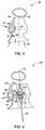
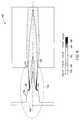
- FIG. 9represents exemplary computational fluid dynamics (CFD) simulation results illustrating premixing capability of a hydrogen premixing device having a Coanda profile in accordance with aspects of the present technique
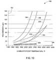
- FIG. 10is a graphical representation of exemplary test results for NOx emissions from combustor of FIG. 1 and for existing combustors employing pure hydrogen as fuel and air as oxidizer in accordance with aspects of the present technique;
- FIG. 11represents exemplary results 210 illustrating degree of premixedness of the premixing device with helium doping using atmospheric air.
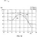
- FIG. 12is a graphical representation of the exemplary results of FIG. 11 in accordance with aspects of the present technique.
- FIG. 1a gas turbine 10 having a low emission combustor 12 is illustrated.
- the gas turbine 10includes a compressor 14 configured to compress ambient air.
- the combustor 12is in flow communication with the compressor 14 and is configured to receive compressed air from the compressor 14 and to combust a fuel stream to generate a combustor exit gas stream.
- the combustor 12includes a can combustor. In an alternate embodiment, the combustor 12 includes a can-annular combustor or a purely annular combustor.
- the gas turbine 10includes a turbine 16 located downstream of the combustor 12 . The turbine 16 is configured to expand the combustor exit gas stream to drive an external load. In the illustrated embodiment, the compressor 14 is driven by the power generated by the turbine 16 via a shaft 18 .
- the combustor 12includes a combustor housing 20 defining a combustion area.
- the combustor 12includes a premixing device for mixing compressed air and fuel stream prior to combustion in the combustion area.
- the premixing deviceemploys a Coanda effect to enhance the mixing efficiency of the device that will be described below with reference to FIGS. 2-5 .
- the term “Coanda effect”refers to the tendency of a stream of fluid to attach itself to a nearby surface and to remain attached even when the surface curves away from the original direction of fluid motion.
- FIG. 2is a diagrammatical illustration of an exemplary configuration of the low emission combustor 22 employed in the gas turbine 10 of FIG. 1 .
- the combustor 22comprises a can combustor.
- the combustor 22includes a combustor casing 24 and a combustor liner 26 disposed within the combustor casing 24 .
- the combustor 22includes a dome plate 28 and a heat shield 30 configured to reduce temperature of the combustor walls.
- the combustor 22includes a plurality of premixing devices 32 for premixing the air and fuel prior to combustion.
- the plurality of premixing devices 32may be arranged to achieve staged fuel introduction within the combustor 22 for applications employing fuels such as hydrogen.
- the premixing device 32receives an airflow 34 and is premixed with the fuel from a fuel plenum. Subsequently, the air-fuel mixture is combusted in the combustor 22 , as represented by reference numeral 36 .
- FIG. 3is a diagrammatical illustration of another exemplary configuration 40 of the low emission combustor employed in the gas turbine 10 of FIG. 1 .
- the combustor 40comprises an annular combustor.
- the combustion area within the combustor 40is defined by the combustor inner and outer casing as represented by reference numeral 42 and 44 , respectively.
- the combustor 40typically includes inner and outer combustor liners 46 and 48 and a dome plate 50 disposed within the combustor 40 .
- the combustor 40includes inner and outer heat shields 52 and 54 disposed adjacent to the inner and outer combustor liners 46 and 48 and a diffuser section 56 for directing an air flow 58 inside the combustion area.
- the combustor 40also includes a plurality of premixing devices 60 disposed upstream of the combustion area.
- a respective premixing device 60receives fuel from a fuel plenum via fuel lines 62 and 64 , which fuel is directed to flow over a pre-determined profile inside the premixing device 60 for enhancing the mixing efficiency of the premixing device 60 and entraining air using the Coanda effect.
- the fuel from the fuel lines 62 and 64is mixed with the incoming air flow 58 to form a fuel-air mixture for combustion 66 .
- the introduction of fuelalters the air splits within the combustor 40 .
- the dilution airis substantially reduced and the combustion air split increases within the combustor 40 due to change in pressure on account of the Coanda effect.
- the details of the premixing device 60 with the pre-determined profilewill be described in detail below with reference to FIGS. 4 and 5 .
- FIG. 4is a diagrammatical illustration of an exemplary configuration 70 of the premixing device employed in the combustors of FIGS. 2 and 3 .
- the premixing device 70includes a fuel line 72 for directing the fuel inside a fuel plenum of the premixing device 70 .
- the air inlet nozzle profile of the premixing device 70 and the air inletare represented by reference numerals 74 and 76 .
- the premixing device 70includes a nozzle outlet 78 , a diffuser wall 80 and a throat area 82 .
- the premixing device 70receives the fuel from a fuel plenum 84 and the fuel is directed to flow over a pre-determined profile 86 or over a set of slots or orifices through a fuel outlet annulus 88 . Subsequently, the fuel is mixed with incoming air from the air inlet 76 to form a fuel-air mixture.
- FIG. 5is a diagrammatical illustration of another exemplary configuration of the premixing device 90 employed in the combustors of FIGS. 2 and 3 , for substantially larger air flows and fuel staging capabilities.
- the premixing device 90includes a dual-mixing configuration nozzle that facilitates wall and center mixing.
- the premixing device 90includes fuel inlet lines 92 and 94 and fuel plenums 96 and 98 to independently provide the fuel for wall and center mixing.
- the diffuser wall and the center bodyare represented by reference numerals 100 and 102 respectively.
- the fuel from the fuel plenums 96 and 98is directed to flow over pre-determined profiles 104 and 106 via the fuel outlets 108 and 110 .
- the premixing device 90receives an airflow along the centerline 112 of the device 90 and facilitates mixing of the air and fuel within the device 90 .
- the pre-determined profilemay be designed to facilitate the mixing within the premixing device based on the Coanda effect that will be described in greater detail below.
- the embodiment illustrated aboveis particularly utilized if the number of premixing devices 90 is required to be reduced in the combustor 40 and the size of the devices 90 is increased for obtaining scale-up of the system.
- the fuel center bodyis employed to maintain the desired degree of premixing with the larger scale system.
- the center bodymay or may not be movable along the axial direction.
- this configurationalso allows staging by independently operating a desired number of premixing devices 90 in the combustor 40 with either center body or the wall fuel supply.
- this configurationfacilitates improved turndown, substantially lower emissions and combustion dynamics.
- FIG. 6is a cross-sectional view of an exemplary configuration 120 of the premixing device employed in the combustor 12 of FIG. 1 .
- the premixing device 120includes an air inlet 122 configured to introduce compressed air into a mixing chamber 124 of the premixing device 120 .
- the premixing device 120includes a fuel plenum 126 configured to provide a fuel to the mixing chamber 124 via a circumferential slot 128 .
- the fuel introduced via the circumferential slot 128is deflected over a pre-determined profile 130 as represented by reference numeral 132 .
- the premixing device 120has an annular configuration and the fuel is introduced radially in and across the pre-determined profile 130 .
- the geometry and dimensions of the pre-determined profile 130may be selected/optimized based upon a desired premixing efficiency and the operational conditions including factors such as, but not limited to, fuel pressure, fuel temperature, temperature of incoming air, and fuel injection velocity.
- fuelinclude natural gas, high hydrogen gas, hydrogen, biogas, carbon monoxide and syngas.
- the pre-determined profile 130facilitates attachment of the introduced fuel to the profile 130 to form a fuel boundary layer based upon the Coanda effect. Additionally, the fuel boundary layer formed adjacent the pre-determined profile 130 facilitates air entrainment thereby enhancing the mixing efficiency of the premixing device 120 within the mixing chamber 124 .
- the incoming airis introduced in the premixing device 120 via the air inlet 122 .
- the flow of airmay be introduced through a plurality of air inlets that are disposed upstream or downstream of the circumferential slot 128 to facilitate mixing of the air and fuel within the mixing chamber 124 .
- the fuelmay be injected at multiple locations through a plurality of slots along the length of the premixing device 120 .
- the premixing device 120may include a swirler (not shown) disposed upstream of the device 120 for providing a swirl movement in the air introduced in the mixing chamber 124 .
- a swirler(not shown) is disposed at the fuel inlet gap for introducing swirling movement to the fuel flow across the pre-determined profile 130 .
- the air swirleris placed at the same axial level and co-axial with the premixing device 120 , at the outlet plane from the premixing device 120 .
- the premixing device 120also includes a diffuser 134 having a straight or divergent profile for directing the fuel-air mixture formed in the mixing chamber 124 to the combustion section via an outlet 136 .
- the angle for the diffuser 134is in a range of about +/ ⁇ 0 degrees to about 25 degrees.
- the degree of premixing of the premixing device 120is controlled by a plurality of factors such as, but not limited to, the fuel type, geometry of the pre-determined profile 130 , degree of pre-swirl of the air, size of the circumferential slot 128 , fuel pressure, fuel temperature, temperature of incoming air, length and angle of diffuser 134 and fuel injection velocity.
- the fuel temperatureis in a range of about 0° F. to about 500° F. and the temperature of the incoming air is in the range of about 100° F. to about 1300° F.
- the premixing of fuel and air within the mixing chamber 124is described below with reference to FIGS. 7 and 8 .
- FIG. 7is a diagrammatical illustration of flow profiles 140 of air and fuel within the premixing device 120 of FIG. 6 .
- a fuel 142is directed inside the premixing device 120 (see FIG. 6 ) and over a pre-determined profile 144 .
- a pump 146may be employed to boost the fuel pressure of fuel 142 from the fuel plenum 126 (see FIG. 6 ).
- the fuel 142is introduced into the premixing device 120 at a substantially high velocity.
- the pre-determined profile 144facilitates attachment of the fuel with the profile 46 to form a fuel boundary layer 148 .
- the geometry and the dimensions of the profile 144are optimized to achieve a desired premixing efficiency.
- a flow of incoming air 150is entrained by the fuel boundary layer 148 to form a shear layer 152 with the fuel boundary layer 148 for promoting the mixing of the incoming air 150 and fuel 142 .
- the fuel 142is supplied at a pressure relatively higher than the pressure of the incoming air 150 .
- the fuel pressureis about 1% to about 25% greater than the pressure of the incoming air 150 .
- the mixing of the air 150 and fuel 142is enhanced due to the separation of the fuel boundary layer 148 downstream of the location of its introduction due to a negative pressure gradient.
- the shear layer 152 formed by the detachment and mixing of the boundary layer 148 with the entrained air 150facilitates formation of a rapid and uniform mixture within the premixing device 120 .
- the emerging mixed flow from the premixing device 120is flow stabilized using an external moderate swirler disposed downstream of the premixing device 120 .
- the fuel 142may be introduced with a swirled movement across the profile 144 .
- the Coanda effect generated within the premixing device 120facilitates a relatively high degree of premixing prior to combustion thereby substantially reducing pollutant emissions from a combustion system.
- the ability of the fuel to attach to the profile 144 due to the Coanda effect and subsequent air entrainmentresults in a relatively high premixing efficiency of the premixing device 120 before combustion 154 .
- the attachment of fuel 142 to the profile 144 due to the Coanda effect in the premixing device 120will be described in detail below with reference to FIG. 8 .
- FIG. 8is a diagrammatical illustration of the formation of fuel boundary layer adjacent the profile 144 in the premixing device of FIG. 7 based upon the Coanda effect.
- the fuel flow 142attaches to the profile 144 and remains attached even when the surface of the profile 144 curves away from the initial fuel flow direction. More specifically, as the fuel flow 142 accelerates to balance the momentum transfer there is a pressure difference across the flow, which deflects the fuel flow 142 closer to the surface of the profile 144 . As will be appreciated by one skilled in the art as the fuel 142 moves across the profile 144 , a certain amount of skin friction occurs between the fuel flow 142 and the profile 144 .
- This resistance to the flow 142deflects the fuel 142 towards the profile 144 thereby causing it to stick to the profile 144 .
- the fuel boundary layer 148 formed by this mechanismentrains incoming airflow 150 to form a shear layer 152 with the fuel boundary layer 148 to promote mixing of the airflow 150 and fuel 142 .
- injection of fuel through a circumferential slot and across a profile designed to facilitate Coanda effectgenerates a driving force that drives an oxidizer, such as air to accelerate.
- the shear layer 152 formed by the detachment and mixing of the fuel boundary layer 148 with the entrained air 150results in a uniform mixture.
- FIG. 9represents exemplary computational fluid dynamics (CFD) simulation results 162 for a hydrogen premixing device 164 having a Coanda profile.
- the hydrogen premixing device 164receives air from an air inlet 166 and the fuel is introduced into the device from a fuel inlet 168 and over a pre-determined profile 170 .
- the mixing of the incoming air and hydrogenis achieved in a mixing zone 172 and the fuel-air mixture is released via a nozzle outlet 174 .
- the test results for mixture fraction in the mixing zone 172 and a lean flame region 176are represented by reference numerals 178 - 186 .
- the term “mixture fraction”refers to the volumetric amount of hydrogen in the air.
- the premixing device having a Coanda profilepromotes the mixing of hydrogen and air prior to combustion. Further, inside the downstream tube the rich zones are substantially eliminated due to the enhanced premixing. In addition, hydrogen sticks to the walls of the premixing device 164 and the stoichiometry there does not allow a flame to exist there thereby enabling reduced temperatures adjacent to the walls of the premixing device 164 . In particular, the negative pressure gradient of the fuel-air mixture within the premixing device 164 substantially prevents the attachment of the fuel adjacent to the walls of the premixing device 164 .
- FIG. 10is a graphical representation of exemplary test results 190 for NOx emissions from combustor of FIG. 1 and for existing combustors employing pure hydrogen as fuel and air as oxidizer.
- the ordinate axis 192represents the NO x emissions measured in parts per million (ppm) and the abscissa axis 194 represents combustor exit temperature measured in ° F.
- the emissions from existing combustorsare represented by profiles 196 - 204 .
- 206represents emission profile from the combustor having the premixing device as described above.
- emissions 206 from the combustor employing the premixing device based upon the Coanda effectare substantially lower than the emissions 196 - 204 from existing combustors.
- the premixing device described abovefacilitates enhanced premixing of the fuel and air prior to combustion thereby substantially reducing the emissions.
- FIG. 11represents exemplary results 210 illustrating degree of non-reacting gases premixedness of the premixing device with helium supplied as fuel and using atmospheric air entrained in the mixer.
- reference numerals 212 and 214represent results for helium supply pressures of about 9 psig and 15 psig at about 0.4 inches above the exit of the premixing device.
- reference numeral 216indicates the time of measurement
- 218indicates the percentage traverse (i.e., the position of probe in percentage of the diameter size, with 50% being the centerline and 100% the wall of the mixer). It should be noted that the percentage traverse is measured along the diameter of the premixing device at about 0.4 inches above the exit of the premixing device.
- reference numerals 220 and 222indicate the measured percentage of helium and oxygen respectively and reference numeral 224 represents the measured percentage of carbon monoxide along with nitrogen in the mixture.
- a mass spectrometeris employed to simultaneously measure the percentage of helium, oxygen, carbon monoxide and nitrogen from a sample of the mixture extracted at various traverse positions.
- the exemplary results 210 of the premixing device for the helium plenum (or supply) pressure levels 9 psig and 15 psigare further illustrated as a graphical representation 230 in FIG. 12 .
- the ordinate axis 232is indicative of the helium concentration and therefore degree of premixedness and the abscissa axis 234 represents distance from the centerline of the premixing device.
- a profile 236represents the helium concentration in the mixture and therefore degree of premixedness for the doping level of 9 psig and a profile 238 represents the helium volumetric concentration in the mixture and therefore degree of premixedness for the doping level of 15 psig.
- the profiles 236 and 238are substantially uniform thus indicating a high degree of premixedness due to the entrainment of atmospheric air within the premixing device via the Coanda effect described above.
- a gas to liquid systemincludes an air separation unit, a gas processing unit and a combustor.
- the air separation unitseparates oxygen from air and the gas processing unit prepares natural gas for conversion in the combustor.
- the oxygen from the air separation unit and the natural gas from the gas processing unitare directed to the combustor where the natural gas and the oxygen are reacted at an elevated temperature and pressure to produce a synthesis gas.
- the premixing deviceis coupled to the combustor to facilitate the premixing of oxygen and the natural gas prior to reaction in the combustor.
- At least one surface of the premixing devicehas a pre-determined profile, wherein the pre-determined profile deflects the oxygen to facilitate attachment of the oxygen to the profile to form a boundary layer, and wherein the boundary layer entrains incoming natural gas to enable the mixing of the natural gas and oxygen at very high fuel to oxygen equivalence ratios (e.g. about 3.5 up to about 4 and beyond) to maximize syngas production yield while minimizing residence time.
- steammay be added to the oxygen or the fuel to enhance the process efficiency.
- the synthesis gasis then quenched and introduced into a Fischer-Tropsh processing unit, where through catalysis, the hydrogen gas and carbon monoxide are recombined into long-chain liquid hydrocarbons. Finally, the liquid hydrocarbons are converted and fractionated into products in a cracking unit.
- the premixing devicebased on the Coanda effect facilitates rapid premixing of the natural gas and oxygen and a substantially short residence time in the gas to liquid system.
- the various aspects of the method described hereinabovehave utility in different applications such as combustors employed in gas turbines and heating devices such as furnaces. Furthermore, the technique described here enhances the premixing of fuel and air prior to combustion thereby substantially reducing emissions and enhancing the efficiency of systems like gas turbines, internal combustion engines and appliance gas burners.
- the premixing techniquecan be employed for different fuels such as, but not limited to, gaseous fossil fuels of high and low volumetric heating values including natural gas, hydrocarbons, carbon monoxide, hydrogen, biogas and syngas.
- the premixing devicemay be employed in fuel flexible combustors for integrated gasification combined cycle (IGCC) for reducing pollutant emissions.
- IGCCintegrated gasification combined cycle
- the premixing devicemay be employed in gas range appliances.
- the premixing deviceis employed in aircraft engine hydrogen combustors and other gas turbine combustors for aero-derivatives and heavy-duty machines.
- the premixing device describedmay facilitate substantial reduction in emissions for systems that employ fuel types ranging from low British Thermal Unit (BTU) to high hydrogen and pure hydrogen Wobbe indices.
- the premixing devicemay be utilized to facilitate partial mixing of streams such as oxy-fuel that will be particularly useful for carbon dioxide free cycles and exhaust gas recirculation.
- the premixing techniquebased upon the Coanda effect described above enables enhanced premixing and flame stabilization in a combustor. Further, the present technique enables reduction of emissions, particularly NOx emissions from such combustors thereby facilitating the operation of the gas turbine in an environmentally friendly manner. In certain embodiments, this technique facilitates minimization of pressure drop across the combustors, more particularly in hydrogen combustors. In addition, the enhanced premixing achieved through the Coanda effect facilitates enhanced turndown, flashback resistance and increased flameout margin for the combustors.
- the fuel boundary layer to the walls via the Coanda effectresults in substantially higher level of fuel concentration at the wall including at the outlet plane of the premixing device.
- the turndownbenefits from the presence of the higher concentration of fuel at the wall thereby stabilizing the flame.
- the absence of a flammable mixture next to the wall and the presence of 100% fuel at the wallsdetermine the absence of the flame in that region, thereby facilitating enhanced flashback resistance.
- the flameis kept away from the walls thus facilitating better turndown thereby allowing for operation on natural gas and air as low as having an equivalence ratio of about 0.2. Additionally, the flameout margin is significantly improved as compared to existing systems.
- this systemmay be used with a variety of fuels thus providing fuel flexibility.
- the systemmay employ either NG or H2, for instance, as the fuel.
- the fuel flexibility of such systemeliminates the need of hardware changes or complicated architectures with different fuel ports required for different fuels.
- the premixing device described abovemay be employed with a variety of fuels thus providing fuel flexibility of the system.
- the technique described abovemay be employed in the existing can or can-annular combustors to reduce emissions and any dynamic oscillations and modulation within the combustors.
- the illustrated devicemay be employed as a pilot in operating existing combustors.
Landscapes
- Engineering & Computer Science (AREA)
- Chemical & Material Sciences (AREA)
- Combustion & Propulsion (AREA)
- Mechanical Engineering (AREA)
- General Engineering & Computer Science (AREA)
Abstract
Description
Claims (30)
Priority Applications (1)
| Application Number | Priority Date | Filing Date | Title |
|---|---|---|---|
| US11/273,212US8266911B2 (en) | 2005-11-14 | 2005-11-14 | Premixing device for low emission combustion process |
Applications Claiming Priority (1)
| Application Number | Priority Date | Filing Date | Title |
|---|---|---|---|
| US11/273,212US8266911B2 (en) | 2005-11-14 | 2005-11-14 | Premixing device for low emission combustion process |
Publications (2)
| Publication Number | Publication Date |
|---|---|
| US20070107436A1 US20070107436A1 (en) | 2007-05-17 |
| US8266911B2true US8266911B2 (en) | 2012-09-18 |
Family
ID=38039338
Family Applications (1)
| Application Number | Title | Priority Date | Filing Date |
|---|---|---|---|
| US11/273,212Expired - Fee RelatedUS8266911B2 (en) | 2005-11-14 | 2005-11-14 | Premixing device for low emission combustion process |
Country Status (1)
| Country | Link |
|---|---|
| US (1) | US8266911B2 (en) |
Cited By (19)
| Publication number | Priority date | Publication date | Assignee | Title |
|---|---|---|---|---|
| US20130048098A1 (en)* | 2005-12-15 | 2013-02-28 | Gulfstream Aerospace Corporation | Supersonic aircraft jet engine installation |
| CN105402772A (en)* | 2015-12-07 | 2016-03-16 | 北京航空航天大学 | Pneumatic steady flame center staged combustor |
| US9677513B2 (en) | 2014-07-08 | 2017-06-13 | David L. Wilson | Mechanically induced vacuum driven delivery system providing pre-vaporized fuel to an internal combustion engine |
| US9976522B2 (en) | 2016-04-15 | 2018-05-22 | Solar Turbines Incorporated | Fuel injector for combustion engine and staged fuel delivery method |
| US10234142B2 (en) | 2016-04-15 | 2019-03-19 | Solar Turbines Incorporated | Fuel delivery methods in combustion engine using wide range of gaseous fuels |
| US10247155B2 (en) | 2016-04-15 | 2019-04-02 | Solar Turbines Incorporated | Fuel injector and fuel system for combustion engine |
| US20200378597A1 (en)* | 2016-06-03 | 2020-12-03 | BSH Hausgeräte GmbH | Gas burner and domestic cooking appliance |
| US11835235B1 (en) | 2023-02-02 | 2023-12-05 | Pratt & Whitney Canada Corp. | Combustor with helix air and fuel mixing passage |
| US11867392B1 (en) | 2023-02-02 | 2024-01-09 | Pratt & Whitney Canada Corp. | Combustor with tangential fuel and air flow |
| US11867400B1 (en) | 2023-02-02 | 2024-01-09 | Pratt & Whitney Canada Corp. | Combustor with fuel plenum with mixing passages having baffles |
| US11873993B1 (en) | 2023-02-02 | 2024-01-16 | Pratt & Whitney Canada Corp. | Combustor for gas turbine engine with central fuel injection ports |
| US12060997B1 (en) | 2023-02-02 | 2024-08-13 | Pratt & Whitney Canada Corp. | Combustor with distributed air and fuel mixing |
| US12111056B2 (en) | 2023-02-02 | 2024-10-08 | Pratt & Whitney Canada Corp. | Combustor with central fuel injection and downstream air mixing |
| US12259135B2 (en) | 2023-02-02 | 2025-03-25 | Pratt & Whitney Canada Corp. | Combustor with fuel and air mixing plenum |
| US12331932B2 (en) | 2022-01-31 | 2025-06-17 | General Electric Company | Turbine engine fuel mixer |
| US12339005B2 (en) | 2023-02-02 | 2025-06-24 | Rtx Corporation | Hydrogen fuel distributor |
| US12339006B1 (en) | 2023-12-22 | 2025-06-24 | General Electric Company | Turbine engine having a combustion section with a fuel nozzle assembly |
| US12359813B2 (en) | 2021-12-29 | 2025-07-15 | General Electric Company | Engine fuel nozzle and swirler |
| US12442331B2 (en) | 2023-02-02 | 2025-10-14 | Pratt & Whitney Canada Corp. | High shear fuel distributor |
Families Citing this family (8)
| Publication number | Priority date | Publication date | Assignee | Title |
|---|---|---|---|---|
| DE102005003984A1 (en)* | 2005-01-28 | 2006-08-03 | Aixtron Ag | Gas inlet element for a chemical vapor deposition (CVD) reactor useful in CVD reactors with base outlets for introduction of process gas via edge side access holes and mixing chamber upstream of access holes for homogenizing gas composition |
| US7874157B2 (en)* | 2008-06-05 | 2011-01-25 | General Electric Company | Coanda pilot nozzle for low emission combustors |
| US8176739B2 (en)* | 2008-07-17 | 2012-05-15 | General Electric Company | Coanda injection system for axially staged low emission combustors |
| US8763400B2 (en)* | 2009-08-04 | 2014-07-01 | General Electric Company | Aerodynamic pylon fuel injector system for combustors |
| US8863525B2 (en) | 2011-01-03 | 2014-10-21 | General Electric Company | Combustor with fuel staggering for flame holding mitigation |
| US20130081407A1 (en)* | 2011-10-04 | 2013-04-04 | David J. Wiebe | Aero-derivative gas turbine engine with an advanced transition duct combustion assembly |
| KR101889542B1 (en)* | 2017-04-18 | 2018-08-17 | 두산중공업 주식회사 | Combustor Nozzle Assembly And Gas Turbine Having The Same |
| CN111156509A (en)* | 2020-03-09 | 2020-05-15 | 江苏方格热能科技有限公司 | Self-preheating high-speed gasification combustion device and combustion method for fuel non-reversing heat accumulating type combustion system |
Citations (45)
| Publication number | Priority date | Publication date | Assignee | Title |
|---|---|---|---|---|
| US2948117A (en)* | 1956-10-01 | 1960-08-09 | Gen Electric | Afterburner flameholder |
| US3143401A (en)* | 1961-08-17 | 1964-08-04 | Gen Electric | Supersonic fuel injector |
| US3631675A (en) | 1969-09-11 | 1972-01-04 | Gen Electric | Combustor primary air control |
| US3695820A (en)* | 1969-04-19 | 1972-10-03 | Ivor Hawkes | Gas burners |
| US3740945A (en)* | 1969-02-27 | 1973-06-26 | Thiokol Chemical Corp | Injector for rocket motors using high viscosity fuel |
| US3744242A (en) | 1972-01-25 | 1973-07-10 | Gen Motors Corp | Recirculating combustor |
| US3792582A (en)* | 1970-10-26 | 1974-02-19 | United Aircraft Corp | Combustion chamber for dissimilar fluids in swirling flow relationship |
| US3826083A (en) | 1973-07-16 | 1974-07-30 | Gen Motors Corp | Recirculating combustion apparatus jet pump |
| US3876362A (en) | 1973-04-23 | 1975-04-08 | Yasuo Hirose | Method of combustion |
| US3915622A (en)* | 1973-09-18 | 1975-10-28 | British Petroleum Co | Flare |
| US3947216A (en)* | 1973-11-07 | 1976-03-30 | Institutul Pentru Creatie Stiintifica Si Tehnica | Burner for liquid fuels |
| US3954382A (en)* | 1974-04-08 | 1976-05-04 | Yasuo Hirose | Combustion apparatus and method |
| US4037991A (en)* | 1973-07-26 | 1977-07-26 | The Plessey Company Limited | Fluid-flow assisting devices |
| US4073613A (en)* | 1974-06-25 | 1978-02-14 | The British Petroleum Company Limited | Flarestack Coanda burners with self-adjusting slot at pressure outlet |
| US4125361A (en)* | 1975-11-12 | 1978-11-14 | The British Petroleum Company Limited | Baffle |
| US4199934A (en)* | 1975-07-24 | 1980-04-29 | Daimler-Benz Aktiengesellschaft | Combustion chamber, especially for gas turbines |
| US4332547A (en)* | 1979-10-01 | 1982-06-01 | Macdonald Jr James D | Thrust augmenter ejector combustion device |
| US4336017A (en)* | 1977-01-28 | 1982-06-22 | The British Petroleum Company Limited | Flare with inwardly directed Coanda nozzle |
| US5085039A (en) | 1989-12-07 | 1992-02-04 | Sundstrand Corporation | Coanda phenomena combustor for a turbine engine |
| US5251447A (en)* | 1992-10-01 | 1993-10-12 | General Electric Company | Air fuel mixer for gas turbine combustor |
| US5274995A (en)* | 1992-04-27 | 1994-01-04 | General Electric Company | Apparatus and method for atomizing water in a combustor dome assembly |
| US5351477A (en)* | 1993-12-21 | 1994-10-04 | General Electric Company | Dual fuel mixer for gas turbine combustor |
| US5658358A (en)* | 1993-04-08 | 1997-08-19 | Abb Management Ag | Fuel supply system for combustion chamber |
| US5680766A (en)* | 1996-01-02 | 1997-10-28 | General Electric Company | Dual fuel mixer for gas turbine combustor |
| US5778676A (en)* | 1996-01-02 | 1998-07-14 | General Electric Company | Dual fuel mixer for gas turbine combustor |
| US5816049A (en)* | 1997-01-02 | 1998-10-06 | General Electric Company | Dual fuel mixer for gas turbine combustor |
| US5865024A (en)* | 1997-01-14 | 1999-02-02 | General Electric Company | Dual fuel mixer for gas turbine combustor |
| US6050096A (en)* | 1995-09-25 | 2000-04-18 | European Gas Turbines Ltd. | Fuel injector arrangement for a combustion apparatus |
| US6122917A (en)* | 1997-06-25 | 2000-09-26 | Alstom Gas Turbines Limited | High efficiency heat transfer structure |
| US6301900B1 (en)* | 1998-09-17 | 2001-10-16 | Mitsubishi Heavy Industries, Ltd. | Gas turbine combustor with fuel and air swirler |
| US6343927B1 (en)* | 1999-07-23 | 2002-02-05 | Alstom (Switzerland) Ltd | Method for active suppression of hydrodynamic instabilities in a combustion system and a combustion system for carrying out the method |
| US6389798B1 (en)* | 1997-12-18 | 2002-05-21 | Qinetiq Limited | Combustor flow controller for gas turbine |
| US6418726B1 (en)* | 2001-05-31 | 2002-07-16 | General Electric Company | Method and apparatus for controlling combustor emissions |
| US7175423B1 (en)* | 2000-10-26 | 2007-02-13 | Bloom Engineering Company, Inc. | Air staged low-NOx burner |
| US7237384B2 (en)* | 2005-01-26 | 2007-07-03 | Peter Stuttaford | Counter swirl shear mixer |
| US20080078182A1 (en)* | 2006-09-29 | 2008-04-03 | Andrei Tristan Evulet | Premixing device, gas turbines comprising the premixing device, and methods of use |
| US20080104961A1 (en)* | 2006-11-08 | 2008-05-08 | Ronald Scott Bunker | Method and apparatus for enhanced mixing in premixing devices |
| US20080110173A1 (en)* | 2006-11-10 | 2008-05-15 | Ronald Scott Bunker | High expansion fuel injection slot jet and method for enhancing mixing in premixing devices |
| US20080134685A1 (en)* | 2006-12-07 | 2008-06-12 | Ronald Scott Bunker | Gas turbine guide vanes with tandem airfoils and fuel injection and method of use |
| US20080163627A1 (en)* | 2007-01-10 | 2008-07-10 | Ahmed Mostafa Elkady | Fuel-flexible triple-counter-rotating swirler and method of use |
| US7434401B2 (en)* | 2003-08-05 | 2008-10-14 | Japan Aerospace Exploration Agency | Fuel/air premixer for gas turbine combustor |
| US20080315042A1 (en)* | 2007-06-20 | 2008-12-25 | General Electric Company | Thrust generator for a propulsion system |
| US7506496B2 (en)* | 2004-09-23 | 2009-03-24 | Snecma | Effervescent aerodynamic system for injecting an air/fuel mixture into a turbomachine combustion chamber |
| US20090100837A1 (en)* | 2007-10-18 | 2009-04-23 | Ralf Sebastian Von Der Bank | Lean premix burner for a gas-turbine engine |
| US20090314000A1 (en)* | 2008-06-05 | 2009-12-24 | General Electric Company | Coanda pilot nozzle for low emission combustors |
- 2005
- 2005-11-14USUS11/273,212patent/US8266911B2/ennot_activeExpired - Fee Related
Patent Citations (45)
| Publication number | Priority date | Publication date | Assignee | Title |
|---|---|---|---|---|
| US2948117A (en)* | 1956-10-01 | 1960-08-09 | Gen Electric | Afterburner flameholder |
| US3143401A (en)* | 1961-08-17 | 1964-08-04 | Gen Electric | Supersonic fuel injector |
| US3740945A (en)* | 1969-02-27 | 1973-06-26 | Thiokol Chemical Corp | Injector for rocket motors using high viscosity fuel |
| US3695820A (en)* | 1969-04-19 | 1972-10-03 | Ivor Hawkes | Gas burners |
| US3631675A (en) | 1969-09-11 | 1972-01-04 | Gen Electric | Combustor primary air control |
| US3792582A (en)* | 1970-10-26 | 1974-02-19 | United Aircraft Corp | Combustion chamber for dissimilar fluids in swirling flow relationship |
| US3744242A (en) | 1972-01-25 | 1973-07-10 | Gen Motors Corp | Recirculating combustor |
| US3876362A (en) | 1973-04-23 | 1975-04-08 | Yasuo Hirose | Method of combustion |
| US3826083A (en) | 1973-07-16 | 1974-07-30 | Gen Motors Corp | Recirculating combustion apparatus jet pump |
| US4037991A (en)* | 1973-07-26 | 1977-07-26 | The Plessey Company Limited | Fluid-flow assisting devices |
| US3915622A (en)* | 1973-09-18 | 1975-10-28 | British Petroleum Co | Flare |
| US3947216A (en)* | 1973-11-07 | 1976-03-30 | Institutul Pentru Creatie Stiintifica Si Tehnica | Burner for liquid fuels |
| US3954382A (en)* | 1974-04-08 | 1976-05-04 | Yasuo Hirose | Combustion apparatus and method |
| US4073613A (en)* | 1974-06-25 | 1978-02-14 | The British Petroleum Company Limited | Flarestack Coanda burners with self-adjusting slot at pressure outlet |
| US4199934A (en)* | 1975-07-24 | 1980-04-29 | Daimler-Benz Aktiengesellschaft | Combustion chamber, especially for gas turbines |
| US4125361A (en)* | 1975-11-12 | 1978-11-14 | The British Petroleum Company Limited | Baffle |
| US4336017A (en)* | 1977-01-28 | 1982-06-22 | The British Petroleum Company Limited | Flare with inwardly directed Coanda nozzle |
| US4332547A (en)* | 1979-10-01 | 1982-06-01 | Macdonald Jr James D | Thrust augmenter ejector combustion device |
| US5085039A (en) | 1989-12-07 | 1992-02-04 | Sundstrand Corporation | Coanda phenomena combustor for a turbine engine |
| US5274995A (en)* | 1992-04-27 | 1994-01-04 | General Electric Company | Apparatus and method for atomizing water in a combustor dome assembly |
| US5251447A (en)* | 1992-10-01 | 1993-10-12 | General Electric Company | Air fuel mixer for gas turbine combustor |
| US5658358A (en)* | 1993-04-08 | 1997-08-19 | Abb Management Ag | Fuel supply system for combustion chamber |
| US5351477A (en)* | 1993-12-21 | 1994-10-04 | General Electric Company | Dual fuel mixer for gas turbine combustor |
| US6050096A (en)* | 1995-09-25 | 2000-04-18 | European Gas Turbines Ltd. | Fuel injector arrangement for a combustion apparatus |
| US5680766A (en)* | 1996-01-02 | 1997-10-28 | General Electric Company | Dual fuel mixer for gas turbine combustor |
| US5778676A (en)* | 1996-01-02 | 1998-07-14 | General Electric Company | Dual fuel mixer for gas turbine combustor |
| US5816049A (en)* | 1997-01-02 | 1998-10-06 | General Electric Company | Dual fuel mixer for gas turbine combustor |
| US5865024A (en)* | 1997-01-14 | 1999-02-02 | General Electric Company | Dual fuel mixer for gas turbine combustor |
| US6122917A (en)* | 1997-06-25 | 2000-09-26 | Alstom Gas Turbines Limited | High efficiency heat transfer structure |
| US6389798B1 (en)* | 1997-12-18 | 2002-05-21 | Qinetiq Limited | Combustor flow controller for gas turbine |
| US6301900B1 (en)* | 1998-09-17 | 2001-10-16 | Mitsubishi Heavy Industries, Ltd. | Gas turbine combustor with fuel and air swirler |
| US6343927B1 (en)* | 1999-07-23 | 2002-02-05 | Alstom (Switzerland) Ltd | Method for active suppression of hydrodynamic instabilities in a combustion system and a combustion system for carrying out the method |
| US7175423B1 (en)* | 2000-10-26 | 2007-02-13 | Bloom Engineering Company, Inc. | Air staged low-NOx burner |
| US6418726B1 (en)* | 2001-05-31 | 2002-07-16 | General Electric Company | Method and apparatus for controlling combustor emissions |
| US7434401B2 (en)* | 2003-08-05 | 2008-10-14 | Japan Aerospace Exploration Agency | Fuel/air premixer for gas turbine combustor |
| US7506496B2 (en)* | 2004-09-23 | 2009-03-24 | Snecma | Effervescent aerodynamic system for injecting an air/fuel mixture into a turbomachine combustion chamber |
| US7237384B2 (en)* | 2005-01-26 | 2007-07-03 | Peter Stuttaford | Counter swirl shear mixer |
| US20080078182A1 (en)* | 2006-09-29 | 2008-04-03 | Andrei Tristan Evulet | Premixing device, gas turbines comprising the premixing device, and methods of use |
| US20080104961A1 (en)* | 2006-11-08 | 2008-05-08 | Ronald Scott Bunker | Method and apparatus for enhanced mixing in premixing devices |
| US20080110173A1 (en)* | 2006-11-10 | 2008-05-15 | Ronald Scott Bunker | High expansion fuel injection slot jet and method for enhancing mixing in premixing devices |
| US20080134685A1 (en)* | 2006-12-07 | 2008-06-12 | Ronald Scott Bunker | Gas turbine guide vanes with tandem airfoils and fuel injection and method of use |
| US20080163627A1 (en)* | 2007-01-10 | 2008-07-10 | Ahmed Mostafa Elkady | Fuel-flexible triple-counter-rotating swirler and method of use |
| US20080315042A1 (en)* | 2007-06-20 | 2008-12-25 | General Electric Company | Thrust generator for a propulsion system |
| US20090100837A1 (en)* | 2007-10-18 | 2009-04-23 | Ralf Sebastian Von Der Bank | Lean premix burner for a gas-turbine engine |
| US20090314000A1 (en)* | 2008-06-05 | 2009-12-24 | General Electric Company | Coanda pilot nozzle for low emission combustors |
Cited By (22)
| Publication number | Priority date | Publication date | Assignee | Title |
|---|---|---|---|---|
| US9334801B2 (en)* | 2005-12-15 | 2016-05-10 | Gulfstream Aerospace Corporation | Supersonic aircraft jet engine installation |
| US9482155B2 (en) | 2005-12-15 | 2016-11-01 | Gulfstream Aerospace Corporation | Isentropic compression inlet for supersonic aircraft |
| US20130048098A1 (en)* | 2005-12-15 | 2013-02-28 | Gulfstream Aerospace Corporation | Supersonic aircraft jet engine installation |
| US9677513B2 (en) | 2014-07-08 | 2017-06-13 | David L. Wilson | Mechanically induced vacuum driven delivery system providing pre-vaporized fuel to an internal combustion engine |
| CN105402772A (en)* | 2015-12-07 | 2016-03-16 | 北京航空航天大学 | Pneumatic steady flame center staged combustor |
| US9976522B2 (en) | 2016-04-15 | 2018-05-22 | Solar Turbines Incorporated | Fuel injector for combustion engine and staged fuel delivery method |
| US10234142B2 (en) | 2016-04-15 | 2019-03-19 | Solar Turbines Incorporated | Fuel delivery methods in combustion engine using wide range of gaseous fuels |
| US10247155B2 (en) | 2016-04-15 | 2019-04-02 | Solar Turbines Incorporated | Fuel injector and fuel system for combustion engine |
| US20200378597A1 (en)* | 2016-06-03 | 2020-12-03 | BSH Hausgeräte GmbH | Gas burner and domestic cooking appliance |
| US11543122B2 (en)* | 2016-06-03 | 2023-01-03 | BSH Hausgeräte GmbH | Gas burner and domestic cooking appliance |
| US12359813B2 (en) | 2021-12-29 | 2025-07-15 | General Electric Company | Engine fuel nozzle and swirler |
| US12331932B2 (en) | 2022-01-31 | 2025-06-17 | General Electric Company | Turbine engine fuel mixer |
| US11835235B1 (en) | 2023-02-02 | 2023-12-05 | Pratt & Whitney Canada Corp. | Combustor with helix air and fuel mixing passage |
| US11873993B1 (en) | 2023-02-02 | 2024-01-16 | Pratt & Whitney Canada Corp. | Combustor for gas turbine engine with central fuel injection ports |
| US12060997B1 (en) | 2023-02-02 | 2024-08-13 | Pratt & Whitney Canada Corp. | Combustor with distributed air and fuel mixing |
| US12111056B2 (en) | 2023-02-02 | 2024-10-08 | Pratt & Whitney Canada Corp. | Combustor with central fuel injection and downstream air mixing |
| US12259135B2 (en) | 2023-02-02 | 2025-03-25 | Pratt & Whitney Canada Corp. | Combustor with fuel and air mixing plenum |
| US11867400B1 (en) | 2023-02-02 | 2024-01-09 | Pratt & Whitney Canada Corp. | Combustor with fuel plenum with mixing passages having baffles |
| US12339005B2 (en) | 2023-02-02 | 2025-06-24 | Rtx Corporation | Hydrogen fuel distributor |
| US11867392B1 (en) | 2023-02-02 | 2024-01-09 | Pratt & Whitney Canada Corp. | Combustor with tangential fuel and air flow |
| US12442331B2 (en) | 2023-02-02 | 2025-10-14 | Pratt & Whitney Canada Corp. | High shear fuel distributor |
| US12339006B1 (en) | 2023-12-22 | 2025-06-24 | General Electric Company | Turbine engine having a combustion section with a fuel nozzle assembly |
Also Published As
| Publication number | Publication date |
|---|---|
| US20070107436A1 (en) | 2007-05-17 |
Similar Documents
| Publication | Publication Date | Title |
|---|---|---|
| US8266911B2 (en) | Premixing device for low emission combustion process | |
| US7832212B2 (en) | High expansion fuel injection slot jet and method for enhancing mixing in premixing devices | |
| US8176739B2 (en) | Coanda injection system for axially staged low emission combustors | |
| US7874157B2 (en) | Coanda pilot nozzle for low emission combustors | |
| US8099960B2 (en) | Triple counter rotating swirler and method of use | |
| CN112088277B (en) | System and method for improving combustion stability in a gas turbine | |
| US20080163627A1 (en) | Fuel-flexible triple-counter-rotating swirler and method of use | |
| US20080104961A1 (en) | Method and apparatus for enhanced mixing in premixing devices | |
| US20100095649A1 (en) | Staged combustion systems and methods | |
| US20100089066A1 (en) | Cool flame combustion | |
| JP2011027395A (en) | Gas turbine premixing system | |
| US20080295521A1 (en) | Method and apparatus for assembling turbine engines | |
| EP3220050A1 (en) | Burner for a gas turbine | |
| Snyder et al. | Emission and performance of a lean-premixed gas fuel injection system for aeroderivative gas turbine engines | |
| Asai et al. | Multiple-injection dry low-NOx combustor for hydrogen-rich syngas fuel: testing and evaluation of performance in an IGCC pilot plant |
Legal Events
| Date | Code | Title | Description |
|---|---|---|---|
| AS | Assignment | Owner name:GENERAL ELECTRIC COMPANY,NEW YORK Free format text:ASSIGNMENT OF ASSIGNORS INTEREST;ASSIGNOR:EVULET, ANDREI TRISTAN;REEL/FRAME:017237/0437 Effective date:20051114 Owner name:GENERAL ELECTRIC COMPANY, NEW YORK Free format text:ASSIGNMENT OF ASSIGNORS INTEREST;ASSIGNOR:EVULET, ANDREI TRISTAN;REEL/FRAME:017237/0437 Effective date:20051114 | |
| FEPP | Fee payment procedure | Free format text:PAYOR NUMBER ASSIGNED (ORIGINAL EVENT CODE: ASPN); ENTITY STATUS OF PATENT OWNER: LARGE ENTITY | |
| ZAAA | Notice of allowance and fees due | Free format text:ORIGINAL CODE: NOA | |
| ZAAB | Notice of allowance mailed | Free format text:ORIGINAL CODE: MN/=. | |
| ZAAA | Notice of allowance and fees due | Free format text:ORIGINAL CODE: NOA | |
| STCF | Information on status: patent grant | Free format text:PATENTED CASE | |
| FPAY | Fee payment | Year of fee payment:4 | |
| MAFP | Maintenance fee payment | Free format text:PAYMENT OF MAINTENANCE FEE, 8TH YEAR, LARGE ENTITY (ORIGINAL EVENT CODE: M1552); ENTITY STATUS OF PATENT OWNER: LARGE ENTITY Year of fee payment:8 | |
| FEPP | Fee payment procedure | Free format text:MAINTENANCE FEE REMINDER MAILED (ORIGINAL EVENT CODE: REM.); ENTITY STATUS OF PATENT OWNER: LARGE ENTITY | |
| LAPS | Lapse for failure to pay maintenance fees | Free format text:PATENT EXPIRED FOR FAILURE TO PAY MAINTENANCE FEES (ORIGINAL EVENT CODE: EXP.); ENTITY STATUS OF PATENT OWNER: LARGE ENTITY | |
| STCH | Information on status: patent discontinuation | Free format text:PATENT EXPIRED DUE TO NONPAYMENT OF MAINTENANCE FEES UNDER 37 CFR 1.362 | |
| FP | Lapsed due to failure to pay maintenance fee | Effective date:20240918 |