US8265817B2 - Inertial measurement with an imaging sensor and a digitized map - Google Patents
Inertial measurement with an imaging sensor and a digitized mapDownload PDFInfo
- Publication number
- US8265817B2 US8265817B2US12/216,758US21675808AUS8265817B2US 8265817 B2US8265817 B2US 8265817B2US 21675808 AUS21675808 AUS 21675808AUS 8265817 B2US8265817 B2US 8265817B2
- Authority
- US
- United States
- Prior art keywords
- features
- attitude
- scene
- image data
- map
- Prior art date
- Legal status (The legal status is an assumption and is not a legal conclusion. Google has not performed a legal analysis and makes no representation as to the accuracy of the status listed.)
- Expired - Fee Related, expires
Links
Images


Classifications
- G—PHYSICS
- G01—MEASURING; TESTING
- G01C—MEASURING DISTANCES, LEVELS OR BEARINGS; SURVEYING; NAVIGATION; GYROSCOPIC INSTRUMENTS; PHOTOGRAMMETRY OR VIDEOGRAMMETRY
- G01C21/00—Navigation; Navigational instruments not provided for in groups G01C1/00 - G01C19/00
- G01C21/005—Navigation; Navigational instruments not provided for in groups G01C1/00 - G01C19/00 with correlation of navigation data from several sources, e.g. map or contour matching
- F—MECHANICAL ENGINEERING; LIGHTING; HEATING; WEAPONS; BLASTING
- F41—WEAPONS
- F41G—WEAPON SIGHTS; AIMING
- F41G7/00—Direction control systems for self-propelled missiles
- F41G7/34—Direction control systems for self-propelled missiles based on predetermined target position data
- G—PHYSICS
- G01—MEASURING; TESTING
- G01S—RADIO DIRECTION-FINDING; RADIO NAVIGATION; DETERMINING DISTANCE OR VELOCITY BY USE OF RADIO WAVES; LOCATING OR PRESENCE-DETECTING BY USE OF THE REFLECTION OR RERADIATION OF RADIO WAVES; ANALOGOUS ARRANGEMENTS USING OTHER WAVES
- G01S17/00—Systems using the reflection or reradiation of electromagnetic waves other than radio waves, e.g. lidar systems
- G01S17/87—Combinations of systems using electromagnetic waves other than radio waves
- G01S17/875—Combinations of systems using electromagnetic waves other than radio waves for determining attitude
- G—PHYSICS
- G01—MEASURING; TESTING
- G01S—RADIO DIRECTION-FINDING; RADIO NAVIGATION; DETERMINING DISTANCE OR VELOCITY BY USE OF RADIO WAVES; LOCATING OR PRESENCE-DETECTING BY USE OF THE REFLECTION OR RERADIATION OF RADIO WAVES; ANALOGOUS ARRANGEMENTS USING OTHER WAVES
- G01S5/00—Position-fixing by co-ordinating two or more direction or position line determinations; Position-fixing by co-ordinating two or more distance determinations
- G01S5/16—Position-fixing by co-ordinating two or more direction or position line determinations; Position-fixing by co-ordinating two or more distance determinations using electromagnetic waves other than radio waves
- G01S5/163—Determination of attitude
- G—PHYSICS
- G05—CONTROLLING; REGULATING
- G05D—SYSTEMS FOR CONTROLLING OR REGULATING NON-ELECTRIC VARIABLES
- G05D1/00—Control of position, course, altitude or attitude of land, water, air or space vehicles, e.g. using automatic pilots
- G05D1/10—Simultaneous control of position or course in three dimensions
- G05D1/101—Simultaneous control of position or course in three dimensions specially adapted for aircraft
- G05D1/106—Change initiated in response to external conditions, e.g. avoidance of elevated terrain or of no-fly zones
- G—PHYSICS
- G05—CONTROLLING; REGULATING
- G05D—SYSTEMS FOR CONTROLLING OR REGULATING NON-ELECTRIC VARIABLES
- G05D1/00—Control of position, course, altitude or attitude of land, water, air or space vehicles, e.g. using automatic pilots
- G05D1/40—Control within particular dimensions
- G05D1/49—Control of attitude, i.e. control of roll, pitch or yaw
- G—PHYSICS
- G06—COMPUTING OR CALCULATING; COUNTING
- G06T—IMAGE DATA PROCESSING OR GENERATION, IN GENERAL
- G06T7/00—Image analysis
- G06T7/70—Determining position or orientation of objects or cameras
- G06T7/73—Determining position or orientation of objects or cameras using feature-based methods
- G06T7/75—Determining position or orientation of objects or cameras using feature-based methods involving models
- G—PHYSICS
- G01—MEASURING; TESTING
- G01S—RADIO DIRECTION-FINDING; RADIO NAVIGATION; DETERMINING DISTANCE OR VELOCITY BY USE OF RADIO WAVES; LOCATING OR PRESENCE-DETECTING BY USE OF THE REFLECTION OR RERADIATION OF RADIO WAVES; ANALOGOUS ARRANGEMENTS USING OTHER WAVES
- G01S13/00—Systems using the reflection or reradiation of radio waves, e.g. radar systems; Analogous systems using reflection or reradiation of waves whose nature or wavelength is irrelevant or unspecified
- G01S13/87—Combinations of radar systems, e.g. primary radar and secondary radar
- G01S13/876—Combination of several spaced transponders or reflectors of known location for determining the position of a receiver
- G—PHYSICS
- G05—CONTROLLING; REGULATING
- G05D—SYSTEMS FOR CONTROLLING OR REGULATING NON-ELECTRIC VARIABLES
- G05D2109/00—Types of controlled vehicles
- G05D2109/20—Aircraft, e.g. drones
- G—PHYSICS
- G06—COMPUTING OR CALCULATING; COUNTING
- G06T—IMAGE DATA PROCESSING OR GENERATION, IN GENERAL
- G06T2207/00—Indexing scheme for image analysis or image enhancement
- G06T2207/10—Image acquisition modality
- G06T2207/10032—Satellite or aerial image; Remote sensing
- G—PHYSICS
- G06—COMPUTING OR CALCULATING; COUNTING
- G06T—IMAGE DATA PROCESSING OR GENERATION, IN GENERAL
- G06T2207/00—Indexing scheme for image analysis or image enhancement
- G06T2207/30—Subject of image; Context of image processing
- G06T2207/30248—Vehicle exterior or interior
- G06T2207/30252—Vehicle exterior; Vicinity of vehicle
Definitions
- the present inventionrelates in general to the analysis of image data, and more particularly, to a system and method for determining vehicle attitude and position from image data detected by sensors in a vehicle.
- Inertial measurement unitsgenerally make up a large portion of the cost of vehicles equipped with one. They provide inertial referenced velocity and attitude changes to a suite of navigation maintenance algorithms that 1) integrate them into evolving position and velocity estimates for vehicle guidance and 2) calculate pitch, yaw, and roll attitude and rate estimates for autonomous flight control.
- a typical IMUmechanizes three orthogonal accelerometers and gyros.
- the advantage of an IMUis that it provides data from a purely internal frame of reference, requiring measurements only from its internal instrumentation and, therefore, rendering itself immune to jamming and deception.
- the disadvantages of IMUsare 1) their cost and 2) their inherent instrument drift, which manifests itself as an accumulating error in position, velocity, and attitude.
- GPSis a potential alternative, but it does not provide the attitude and attitude rate information required for flight control.
- the present inventionseeks to satisfy navigation requirements and provide attitude data essential for robust vehicle flight control while addressing the issues of cost and instrument drift common to typical IMU systems. It presents an apparatus and method of position, velocity, and attitude measurement that does not require 1) gyros and accelerometers, or 2) the subsequent algorithms to integrate their outputs into a meaningful navigation solution. Instead the invention allows for navigation and attitude estimation based on scene flow information collected as a vehicle traverses diverse patches of mapped terrain.
- An embodiment of the present inventionis a navigation and attitude maintenance system consisting of an imaging sensor, a terrain map, and a unit for image processing and analysis.
- an imaging sensora variety of sensors may be used, including infra-red, millimeter-wave, active or passive radio-frequency, or visible-spectrum imaging.
- a requirement of any sensor used in any embodiment of the inventionis that it measures angle coordinates relative to itself. The angle coordinates may be extracted and analyzed in either the spatial or frequency domain.
- the sensorimages the area that the moving object, which may be an aircraft, a land vehicle, or an aquatic vehicle, is passing through.
- the unitselects at least three points of reference from a captured image and matches these to points on a terrain map, validating them against a known terrestrial location.
- the systemdetermines, based on their location in the image plane, the location and orientation of the moving object the system is installed in.
- Attitudemay be done on an entirely self-contained basis with only relative reference data and a built-in terrain map.
- Attitude datais derived from the absolute location of objects relative to the image plane. This absolute location is derived by extracting an earth-relative line of sight (LOS) angle based on the differences between object locations in the image plane and their locations in a reference map.
- LOSearth-relative line of sight
- the systemcontinues to capture images, it tracks the movement of the matched reference points in the imaging plane and calculates a new location or orientation based on the relative changes in the position of the selected reference points.
- the systemalso continues to acquire new reference points and, when used for navigation, match them against the relevant sections of a terrain map or validate them against updated GPS position data as the moving object continues on its path or trajectory.
- the systemmay be loaded with as few or as many terrain maps as necessary, and may be instructed to identify certain specific features in a scene to better allow it to confirm its location.
- the systemmay be used strictly for “dead reckoning” attitude control or as a primary or a secondary navigation system and may be used for a broad range of applications including detailed reconnaissance where certain features and landscape elements in an area are known, but a more detailed survey of the area is desired.
- the systemmay employ active or passive sensors, and may utilize a plurality of sensors.
- the systemmay also allow for a user to identify specific features for matching against a terrain map or discard automatically selected features from further consideration.
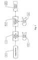
- FIG. 1is a block diagram of an embodiment of the inventive system
- FIG. 2shows the computational elements of an embodiment of the inventive system and their inter-relationship
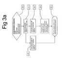
- FIG. 3 ais an algorithmic representation of an embodiment of a navigation system according to the present invention.
- FIG. 3 bis an algorithmic representation of an embodiment of the feature selection portion of the present invention.
- FIG. 3 cis an algorithmic representation of an embodiment of the attitude computation portion of the present invention.
- FIG. 4shows vehicle and ground line of sight computations that may be used to determine relative vehicle position and attitude in an embodiment of the present invention.
- FIG. 5shows a complete logic data flow diagram of an IMU replacement system for computing both location and attitude of a vehicle according to the present invention.
- the present inventioncomprises a method and apparatus for terrain map based navigation and attitude maintenance using: 1) a sensor capable of measuring the angle of a detected entity with respect to the sensor's boresight reference, and 2) a computation system to process the sensor data.
- FIG. 1illustrates an embodiment of the present invention intended for attitude calculation and terrain map-based navigation.
- the imaging element 101may consist of a passive sensor such as a visible-spectrum imaging device, a longwave or mid-wave infra-red detector, a millimeter-wave detector, a passive RF detector, or any other passive sensor capable of measuring the angle of a detected entity with respect to the sensor's boresight reference.
- the imaging element 101may also consist of an active sensor such as RADAR or SONAR.
- the angle data acquired by the imaging element 101may be extracted and analyzed in either the spatial or frequency domain.
- image dataafter image data is acquired, it is passed to an image processing section 111 that selects at least three features from the image data provided by the imaging element 101 .
- the image processing center 111also identifies and tracks features identified and selected in previous frames of image data. If there are still at least three previously identified viable features present in the current frame of image data, the image processing center 111 may not be required to identify and select new features from the image, although more features may be used to reduce error.
- a viable featureis one that meets predetermined detection and selection criteria.
- a viable featuremay be one that is greater than a certain distance away from the edge of the image data, indicating that it will be detected again in a subsequent image frame.
- the certain distance from the edge of the image datais a configurable parameter that may be defined by external input or dynamically adjusted based on the current velocity of the object.
- an embodiment of the system used in a guided missilemay discard features moving away from the center of its field of view (FOV) as non-viable as soon as they are midway between the FOV center and an image edge.
- An embodiment of the system intended for use in a UAVmay wait until a feature is 75% of the way between the FOV center and an image edge before discarding it as non-viable and selecting a new feature to track on.
- viable featuresmay be anything within the FOV. Even the corner of a building or half of a large boulder, split by the edge of the FOV, could be used as a feature for correlation between the image and the map in some embodiments.
- the image processing center 111also selects an appropriate terrain map 141 from a bank of terrain maps 141 and matches the identified features from the image data against features in the terrain map 141 .
- Other embodiments of the inventionmay utilize only internally-loaded terrain maps if the system is being used strictly for relative attitude control and relative position information, and not for any absolute position or orientation data.
- the identified features, along with any relevant terrain map,are next sent to a location and navigation center 121 in this embodiment of the invention.
- the location and navigation center 121performs the actual calculations required to determine attitude, heading, velocity, and position from the acquired image data and any associated location data.
- Location data 151 from prior location calculationsis stored and used to facilitate calculation and track relative changes in attitude and position.
- Alternative embodiments of the inventionmay not require stored location data 151 , especially in instances where the system is being used strictly for attitude measurement and control.
- An example of thisis an embodiment where the system receives GPS data to establish ownship position.
- the location and navigation center 121passes the position and attitude calculations to a guidance system 131 which makes appropriate decisions about course and attitude correction based on the determined position and attitude of the vehicle.
- FIG. 2shows a computer system running an application that processes image data to provide estimated attitude and position data.
- the imaging element 101is an input device 2130 with an interface 2120 to image processing and navigation calculation application programs 2050 and their associated program data 2040 , which are stored in system memory 2020 and operated on by the microprocessor 2070 .
- the application programs 2160 and any associated program data 2170such as terrain maps 141 and location data 151 may be stored in a hard drive 2150 when not in use.
- the system 2010provides relevant attitude and position (depending on the embodiment) data to an output device 2090 such as a guidance system 131 through an output interface 2080 .
- inventive systemmay be implemented purely in hardware, having separate microprocessors 2070 running specialized application programs 2050 for each function of the system.
- inventive systemmay have a hardware configuration conducive to multiple types of navigation, attitude control, and position detection, with the particular algorithms to be used residing on removable media 2110 or other external data sources, and only being loaded into the system prior to use.
- the hardware configurationmay also use FPGAs, ASICs, or other methods to implement the various algorithms.
- the image processing 111 and location and navigation 121 centers in FIG. 1work together to execute an embodiment of an Image Navigation Algorithm, as depicted in FIG. 3 a .
- the algorithmaccepts incoming image data collected by the imaging element 101 as input 301 . Additional input may comprise reference location and velocity information, depending on the specific uses an embodiment of the system is tailored to.
- This embodiment of the algorithmfirst selects and identifies features in the incoming frame of image data 311 . After at least three viable features are identified and correlated with the map, the next steps in this embodiment of the image navigation algorithm 301 are to calculate a vehicle position 321 and attitude 341 with respect to the identified features. These tasks are both accomplished by calculating the line-of-sight angles between the vehicle body and the identified features, and also the line-of-sight angles between the various features with respect to one-another.
- Alternative embodiments of an image navigation algorithm 301may have additional inputs of a reference attitude, or may not have reference location and reference velocity input data.
- the calculation of the position 321may be a relative position or an absolute position.
- the algorithmmay execute a comparison step 331 to compare the current position with a prior position.
- Absolute positionmay omit this step in embodiments that employ a technology such as GPS for absolute location data.
- the new position and heading 351may only be based on a calculated attitude, with the position data being provided by a separate system.
- the output of such alternative embodimentsmay be a calculated attitude and possible course corrections based thereon.
- FIG. 3 bshows an embodiment of the feature identification portion of the present invention.
- Featuresare selected from a frame of image data captured by an imaging sensor in the vehicle.
- Featuresare selected from the pixel space of a given image frame 311 - 1 based on a pre-programmed or dynamically determined set of criteria.
- Different embodiments of the present inventionmay employ different feature selection criteria based on the intended function of the vehicle containing a system according to the present invention and also based on the route and terrain such a vehicle is expected to traverse.
- Embodiments intended for high-speed aerial movement over urban areasfor example, may have a feature selection bias towards buildings and street intersections located towards the front of the image plane relative to the vehicle.
- an embodiment of a system according to the present inventiontransforms the selected feature locations within the image plane into object space angular coordinates 311 - 2 that provide vehicle-relative line-of-sight angle information.
- Alternate embodiments of the present inventionmay employ additional features, or may use a composite image plane composed of input from multiple vehicles to simultaneously provide earth-relative and vehicle-relative attitude information across multiple vehicles equipped with a networked or distributed embodiment of the inventive system.
- An embodiment of the inventive systemalso correlates the selected features from the image plane to features in an image or image chip of a terrain map 311 - 3 .
- Alternative embodiments of the present inventionmay omit this step and instead generate purely relative attitude calculations based on the movement of selected features across image frames over time.
- Yet further alternative embodiments of the present inventionmay have terrain maps at multiple angles, enabling the inventive system to select a map whose angle of imaging most closely matches the selected features in the image data. Such an embodiment may reduce downstream attitude and position calculation operations.
- FIG. 3 cshows an embodiment of the attitude calculation portion of the present invention.
- Features correlated from the electro-optical imaging data gathered by the vehicle to an internal terrain mapare transformed into object-space angular coordinates relative to the terrain map 341 - 1 . These coordinates provide earth-relative line-of-sight angle information for the correlated features
- the terrain map angular coordinatesare then compared against the image data angular coordinates generated during the feature identification process 311 - 2 to compute the horizontal, vertical, and arc-length differences between the two coordinate sets 341 - 2 .
- These differencesare line-of-sight angle differences that enable the determination of variations in viewing angle in the earth-relative and vehicle-relative coordinate sets, and therefore a determination of vehicle attitude relative to earth.
- the vertical differencesrelate to pitch
- the horizontalrelate to roll
- the arc-length to yawBased on these difference values for each selected feature, an earth-relative vehicle attitude may be computed 341 - 3 .
- Embodiments of the present inventionmay store terrain maps internally, in other hardware located in the vehicle, or may communicate with a remote station to request map data or transmit image data for processing and attitude computation.
- velocity and accelerationare calculated based on differences in position over time 331 . After an absolute or relative position is calculated 321 , this information is stored and compared to subsequent position determinations over known time periods to establish velocity and acceleration vectors 331 . The combined position, velocity, acceleration, and attitude data is then provided to a guidance system 351 or similar device.
- Alternative embodiments of the present inventionmay omit velocity and acceleration calculations or calculate these values by alternative methods or means.
- Alternative embodiments of the present inventionmay replace a guidance system with a targeting, tracking, imaging, or range-finding system.
- Yet other alternative embodiments of the present inventionmay replace the feature detection, selection, and terrain map comparison aspects with ground beacons that have broadcast either relative or absolute position information to a vehicle for attitude, position, and/or velocity determinations.
- an electro-optical imaging systemmay be replaced with active or passive beacon search and detection systems.
- FIG. 4illustrates vehicle-centric and ground-centric angle and line-of-sight diagrams for identified features, shown here as survey points, with respect to the vehicle (b).
- Each survey pointcorresponds to an object space angular coordinate set derived from an identified feature in an image plane.
- An identified featuresuch as survey point 1 1001 has three relative spatial coordinates with respect to the vehicle (b).
- the vehicleis assumed to have three orientation vectors in space, ⁇ yb 1002 , ⁇ zb 1003 , ⁇ xb 1004 .
- the line of sight (LOS) 1006 angles to a survey point 1005 , ⁇ y and ⁇ x with respect to the x-direction orientation vector of the vehicle 1004can be translated to the angles ⁇ and ⁇ in the ground frame of reference (R) through the body attitude of the vehicle by using the yaw ⁇ , the pitch ⁇ , and the roll ⁇ Euler angles, but these Euler angle values are unknown prior to calculation.
- the relative line-of-sight coordinates of a survey point with respect to the other survey points from a ground reference frameare determined by comparing their locations in the image frame (the center of the image frame is taken to be a center point for calculation purposes), and the angles between other survey points.
- he relative ground reference LOS coordinates of survey point 1 1001 with respect to survey point 2 1104are determined by comparing their relative locations in the image frame and comparing the angles ⁇ between survey point 2 1104 and the vehicle line of sight to the survey point 1105 and ⁇ between survey point 2 1104 and the x vector on the ground 1101 .
- the ground-reference (R) line of sight (LOS) 1105 that is determined by angles ⁇ and ⁇can be reconstructed for any survey point in the ground reference frame (R) by using a known relative survey point location 1104 and an unknown vehicle position comprised of three coordinates (an x coordinate, a y coordinate, and a z coordinate).
- attitude informationis coupled with feature-tracking information whereby the survey points selected for attitude determination are also matched and tracked against features in a terrain map to ascertain the location and movement rate of the vehicle.
- This combination of attitude and location informationis then sent on to a navigation unit that compares the location and attitude of the vehicle against the expected location and attitude and against any target or destination or flight-path information and makes course corrections as necessary.
- the inventionapplies prevalent techniques of image processing for feature extraction and matching, so a discussion of this aspect of the invention is omitted with the understanding that such techniques are widely known and used in the field of image-based navigation.
- Embodiments of the inventionmay also rely on fixed beacons for location determination.
- RADAR, Infra-red, or visually discernible beaconsmay be positioned along a vehicle's path of travel, and the vehicle may be equipped with some form of range-finding capability or a map containing known beacon locations and positions. Based on this information, the system may discern location data without requiring further image analysis.
- a system that carries out attitude and position estimates according to the process described aboveis illustrated in FIG. 5 .
- a system package of this typemay consist of three passive sensors ( 5030 , 5040 , 5050 ) that measure a line-of-sight (LOS) angle to a ground spot with respect to the sensor mount.
- the sensorsare arranged so that their individual pointing directions ( 1002 , 1003 , 1004 ) are not co-planar.
- Passive sensors suitable for an embodiment of such a systeminclude passive RADAR systems that determine range and direction from an active emitter, passive IR systems that look for ‘hotspot’ beacons, and imaging systems (any type, including visual) whose output is correlated to either previously captured image data or a stored map image chip to establish the direction to the center of an area.
- the embodiment shown in FIG. 5is capable of calculating either attitude only, or attitude and position. Discussing the absolute attitude calculation in an embodiment of the present invention employing passive visual-spectrum imaging sensors; at each imaging time, a ground point 5100 of known location is selected for each passive device from a database 5060 by matching 5115 the video image captured by the sensor to a map or map portion stored in the database. Embodiments of the system may use a range of matching and searching techniques to accomplish this matching, and the limitations on how this matching is accomplished are imposed only by available memory and processing power. Once a map or map portion is selected for each ground point 5100 , the combined surveyed coordinates 5080 and an image chip of the site containing all three ground points 5070 are extracted from the database.
- This image chip 5070is then correlated against each sensor's output video 5090 to extract the LOS angles from the sensor to the ground point 5100 .
- An embodiment of the LOS angle extraction processmay comprise running a correlation of the image to the map to the terrain map using affine transforms (shifts, zoom, roll, flip, and shear) to minimize error.
- An alternative embodiment of this processmay implement the correlation in the frequency domain by multiplying the Fourier transform of the image by the Fourier transform of the map while monitoring the peak as shift, zoom, roll, flip, and shear are varied in either the image or map.
- Yet another alternativemay include correlation after perspective projection.
- Still further alternative embodimentsmay employ holograms and other methods to accomplish angle LOS extraction.
- each sensor's LOS anglesare then converted to earth-relative angles with a position/attitude extract function 5110 , using the best estimate of vehicle attitude 5010 .
- the anglesare converted, they are compared to the earth-relative angles as computed using the appropriate site survey coordinates and the best estimate of the vehicle position 5020 .
- the measurement residual for each siteis processed through a Kalman filter that reckons corrections to the current vehicle position and attitude estimates and their rates.
- the horizontal, vertical, and arc-length differences between the extracted earth relative and calculated map-oriented angles of the survey pointscorrespond to the roll, pitch, and yaw orientations of the sensors relative to earth.
- the attitude extraction function to determine the earth-relative LOS of a sensoris defined by the following equations.
- the LOS unit vector(expressed in the detector coordinate frame) to a particular survey point (i) is computed as a function of the LOS angles ( ⁇ y i and ⁇ z i ) measured relative to the detector:
- x s i ris the geolocation of a surveyed site tracked by the i th sensor
- ⁇ circumflex over (x) ⁇ ris the current estimate of the ship's position.
- An embodiment of a Kalman filterthat reckons corrections in the current vehicle position ( ⁇ circumflex over (x) ⁇ r ) and attitude (C b r ) estimates, based on the residual differences between the two sets of computed Euler angles ( ⁇ circumflex over ( ⁇ ) ⁇ i ( ⁇ circumflex over (x) ⁇ r ) and ⁇ circumflex over ( ⁇ ) ⁇ i (C b r )), may be accomplished using the following set of equations.
- the linear relationship between the residuals and the uncertainties in the position and attitude estimatesis defined by the measurement mapping matrix:
- H ⁇ ( C b r , x ⁇ r )( H 1 ⁇ ( C b r , x ⁇ r ) H 2 ⁇ ( C b r , x ⁇ r ) H 3 ⁇ ( C b r , x ⁇ r ) )
- H i ⁇ ( C b r , x ⁇ r )( F ⁇ ( u ⁇ i r ⁇ ( C b r ) ) ⁇ G ⁇ ( u ⁇ i r ⁇ ( x ⁇ r ) )
- F ⁇ ( u ⁇ i r ⁇ ( C b r ) )( f T ⁇ ( u ⁇ i r ⁇ ( C b r ) ) ⁇ f ⁇ ( u ⁇ i r ⁇ ( C b r ) ) ) - 1 ⁇ f T ⁇ ( u ⁇
- KP ⁇ H T ( C b r , ⁇ circumflex over (x) ⁇ r ) ⁇ [ H ( C b r , ⁇ circumflex over (x) ⁇ r ) ⁇ P ⁇ H T ( C b r , ⁇ circumflex over (x) ⁇ r )+ R] ⁇ 1
- Pis the (6 ⁇ 6) error covariance matrix that represents, statistically, how well the filter thinks it has estimated the states and how correlated it believes the various state errors are with each other.
- Ris the (3 ⁇ 3) measurement noise covariance matrix that defines the fidelity of the three angle measurements and the interrelationship between them.
- the LOS calculationsare done with respect to the signal emitters, eliminating the need for image chips and image correlation.
Landscapes
- Engineering & Computer Science (AREA)
- Physics & Mathematics (AREA)
- Radar, Positioning & Navigation (AREA)
- Remote Sensing (AREA)
- General Physics & Mathematics (AREA)
- Electromagnetism (AREA)
- Automation & Control Theory (AREA)
- Computer Networks & Wireless Communication (AREA)
- Chemical & Material Sciences (AREA)
- Combustion & Propulsion (AREA)
- General Engineering & Computer Science (AREA)
- Aviation & Aerospace Engineering (AREA)
- Computer Vision & Pattern Recognition (AREA)
- Theoretical Computer Science (AREA)
- Navigation (AREA)
Abstract
Description
This is then coordinatized in the navigation reference frame, given the detector to body direction cosine matrix for sensor I (Cd
Next, this same unit LOS unit vector (expressed in the navigation reference frame) is computed using the best estimate of ownship position and knowledge of the survey point geolocation. This is defined by the following equations:
Where
Note that, in these equations,
is the skew symmetric matrix equivalent to the vector (ûir) in a cross product sense.
K=P·HT(Cbr,{circumflex over (x)}r)·[H(Cbr,{circumflex over (x)}r)·P·HT(Cbr,{circumflex over (x)}r)+R]−1
Where P is the (6×6) error covariance matrix that represents, statistically, how well the filter thinks it has estimated the states and how correlated it believes the various state errors are with each other. In addition, R is the (3×3) measurement noise covariance matrix that defines the fidelity of the three angle measurements and the interrelationship between them. The corrections to the states are then computed via the equation:
At this point the corrections are applied to the position estimate via the relationship:
And to the direction cosine matrix estimate through the equations:
Finally, the filter estimation error covariance matrix is updated, reflecting the fidelity of the measurements and their applicability in enhancing the quality of the position and attitude estimates,
S=(I−K·H(Cbr,{circumflex over (x)}r))·P·(I−K·H(Cbr,{circumflex over (x)}r))T+K·R·KT
And then propagated forward in time, accounting for the random growth in uncertainty pertinent to the dynamics model,
P=S+Q·Δt
Claims (26)
Priority Applications (6)
| Application Number | Priority Date | Filing Date | Title |
|---|---|---|---|
| US12/216,758US8265817B2 (en) | 2008-07-10 | 2008-07-10 | Inertial measurement with an imaging sensor and a digitized map |
| SG200904132-8ASG158793A1 (en) | 2008-07-10 | 2009-06-15 | Inertial measurement with an imaging sensor and a digitized map |
| EP09162968.3AEP2144038A3 (en) | 2008-07-10 | 2009-06-17 | Inertial measurement using an imaging sensor and a digitized map |
| CA2670310ACA2670310C (en) | 2008-07-10 | 2009-06-26 | Inertial measurement with an imaging sensor and a digitized map |
| KR1020090059967AKR101193638B1 (en) | 2008-07-10 | 2009-07-01 | Inertial measurement with an imaging sensor and a digitized map |
| US13/593,402US8515611B2 (en) | 2008-07-10 | 2012-08-23 | Inertial measurement with an imaging sensor and a digitized map |
Applications Claiming Priority (1)
| Application Number | Priority Date | Filing Date | Title |
|---|---|---|---|
| US12/216,758US8265817B2 (en) | 2008-07-10 | 2008-07-10 | Inertial measurement with an imaging sensor and a digitized map |
Related Child Applications (1)
| Application Number | Title | Priority Date | Filing Date |
|---|---|---|---|
| US13/593,402DivisionUS8515611B2 (en) | 2008-07-10 | 2012-08-23 | Inertial measurement with an imaging sensor and a digitized map |
Publications (2)
| Publication Number | Publication Date |
|---|---|
| US20100010741A1 US20100010741A1 (en) | 2010-01-14 |
| US8265817B2true US8265817B2 (en) | 2012-09-11 |
Family
ID=41202537
Family Applications (2)
| Application Number | Title | Priority Date | Filing Date |
|---|---|---|---|
| US12/216,758Expired - Fee RelatedUS8265817B2 (en) | 2008-07-10 | 2008-07-10 | Inertial measurement with an imaging sensor and a digitized map |
| US13/593,402Expired - Fee RelatedUS8515611B2 (en) | 2008-07-10 | 2012-08-23 | Inertial measurement with an imaging sensor and a digitized map |
Family Applications After (1)
| Application Number | Title | Priority Date | Filing Date |
|---|---|---|---|
| US13/593,402Expired - Fee RelatedUS8515611B2 (en) | 2008-07-10 | 2012-08-23 | Inertial measurement with an imaging sensor and a digitized map |
Country Status (5)
| Country | Link |
|---|---|
| US (2) | US8265817B2 (en) |
| EP (1) | EP2144038A3 (en) |
| KR (1) | KR101193638B1 (en) |
| CA (1) | CA2670310C (en) |
| SG (1) | SG158793A1 (en) |
Cited By (13)
| Publication number | Priority date | Publication date | Assignee | Title |
|---|---|---|---|---|
| US20120320195A1 (en)* | 2008-07-10 | 2012-12-20 | Tener Gene D | Inertial measurement with an imaging sensor and a digitized map |
| US20130166137A1 (en)* | 2011-12-23 | 2013-06-27 | Samsung Electronics Co., Ltd. | Mobile apparatus and localization method thereof |
| US20140371952A1 (en)* | 2013-06-14 | 2014-12-18 | Kabushiki Kaisha Topcon | Flying Vehicle Guiding System And Flying Vehicle Guiding Method |
| US20150073704A1 (en)* | 2012-09-07 | 2015-03-12 | Mando Corporation | Apparatus and method for calculating distance between vehicles |
| US20160040999A1 (en)* | 2014-03-26 | 2016-02-11 | Trip Routing Technologies, Llc. | Selected driver notification of transitory roadtrip events |
| US9409656B2 (en) | 2013-02-28 | 2016-08-09 | Kabushiki Kaisha Topcon | Aerial photographing system |
| US9528834B2 (en) | 2013-11-01 | 2016-12-27 | Intelligent Technologies International, Inc. | Mapping techniques using probe vehicles |
| US9733082B2 (en) | 2014-11-12 | 2017-08-15 | Kabushiki Kaisha Topcon | Tilt detecting system and tilt detecting method |
| US9773420B2 (en) | 2014-01-31 | 2017-09-26 | Kabushiki Kaisha Topcon | Measuring system |
| US9958268B2 (en) | 2013-10-31 | 2018-05-01 | Kabushiki Kaisha Topcon | Three-dimensional measuring method and surveying system |
| US11543257B2 (en) | 2019-11-12 | 2023-01-03 | Samsung Electronics Co., Ltd. | Navigation apparatus and operation method of navigation apparatus |
| US20230115712A1 (en)* | 2021-10-07 | 2023-04-13 | L3Harris Technologies, Inc. | Estimation of Target Location and Sensor Misalignment Angles |
| US20250035436A1 (en)* | 2023-07-27 | 2025-01-30 | Aptiv Technologies Limited | NLS Using a Bounded Linear Initial Search Space and a Fixed Grid with Pre-Calculated Variables |
Families Citing this family (33)
| Publication number | Priority date | Publication date | Assignee | Title |
|---|---|---|---|---|
| WO2011120141A1 (en)* | 2010-03-31 | 2011-10-06 | Ambercore Software Inc. | Dynamic network adjustment for rigorous integration of passive and active imaging observations into trajectory determination |
| US8833695B2 (en)* | 2011-10-17 | 2014-09-16 | Eaton Corporation | Aircraft hydraulic air bleed valve system |
| US8979021B2 (en)* | 2011-10-17 | 2015-03-17 | Easton Corporation | Hydraulic air bleed valve system |
| CN102706330B (en)* | 2012-05-29 | 2013-11-27 | 中国科学院长春光学精密机械与物理研究所 | The Method of Shooting the Special-shaped Strip Target on the Ground with the Space Camera |
| GB201218963D0 (en) | 2012-10-22 | 2012-12-05 | Bcb Int Ltd | Micro unmanned aerial vehicle and method of control therefor |
| FR2998363B1 (en)* | 2012-11-19 | 2015-01-02 | Inria Inst Nat Rech Informatique & Automatique | METHOD FOR DETERMINING, IN A 3D FIXED REFERENTIAL, THE LOCATION OF A MOVING GEAR, ASSOCIATED DEVICE AND COMPUTER PROGRAM |
| US9082008B2 (en)* | 2012-12-03 | 2015-07-14 | Honeywell International Inc. | System and methods for feature selection and matching |
| US11039108B2 (en)* | 2013-03-15 | 2021-06-15 | James Carey | Video identification and analytical recognition system |
| US9903719B2 (en)* | 2013-09-03 | 2018-02-27 | Litel Instruments | System and method for advanced navigation |
| US9383209B2 (en)* | 2013-09-23 | 2016-07-05 | Texas Instruments Incorporated | Undocking and re-docking mobile device inertial measurement unit from vehicle |
| US10250821B2 (en)* | 2013-11-27 | 2019-04-02 | Honeywell International Inc. | Generating a three-dimensional model of an industrial plant using an unmanned aerial vehicle |
| US9360321B2 (en) | 2014-04-14 | 2016-06-07 | Vricon Systems Aktiebolag | Navigation based on at least one sensor and a three dimensional map |
| US9483842B2 (en) | 2014-04-14 | 2016-11-01 | Vricon Systems Aktiebolag | Navigation based on at least one sensor and a three dimensional map |
| JP6320542B2 (en) | 2015-05-23 | 2018-05-09 | エスゼット ディージェイアイ テクノロジー カンパニー リミテッドSz Dji Technology Co.,Ltd | Method, system, and program for estimating one or more external parameters for a movable object having a plurality of sensors having an initial configuration |
| CN106170676B (en)* | 2015-07-14 | 2018-10-09 | 深圳市大疆创新科技有限公司 | Method, equipment and the system of movement for determining mobile platform |
| US9862488B2 (en) | 2015-08-28 | 2018-01-09 | Mcafee, Llc | Location verification and secure no-fly logic for unmanned aerial vehicles |
| US10401235B2 (en)* | 2015-09-11 | 2019-09-03 | Qualcomm Incorporated | Thermal sensor placement for hotspot interpolation |
| CN105676865B (en)* | 2016-04-12 | 2018-11-16 | 北京博瑞云飞科技发展有限公司 | Method for tracking target, device and system |
| US20180089539A1 (en)* | 2016-09-23 | 2018-03-29 | DunAn Precision, Inc. | Eye-in-hand Visual Inertial Measurement Unit |
| DE102017210050B3 (en)* | 2017-06-14 | 2018-12-06 | Elektrobit Automotive Gmbh | Method for determining a position |
| CN110020394B (en)* | 2017-08-01 | 2023-07-18 | 广州极飞科技股份有限公司 | Method and device for data processing |
| US10685229B2 (en) | 2017-12-21 | 2020-06-16 | Wing Aviation Llc | Image based localization for unmanned aerial vehicles, and associated systems and methods |
| US10757358B1 (en)* | 2019-06-05 | 2020-08-25 | Primesensor Technology Inc. | Photographing device having two output interfaces |
| CN110360999B (en) | 2018-03-26 | 2021-08-27 | 京东方科技集团股份有限公司 | Indoor positioning method, indoor positioning system, and computer readable medium |
| CN108731672B (en)* | 2018-05-30 | 2022-03-11 | 中国矿业大学 | Shearer attitude detection system and method based on binocular vision and inertial navigation |
| KR102169701B1 (en)* | 2019-02-26 | 2020-10-26 | 경기과학기술대학교 산학협력단 | System for colleting marine waste |
| IL265818A (en)* | 2019-04-02 | 2020-10-28 | Ception Tech Ltd | System and method for determining location and orientation of an object in a space |
| CN112050806B (en)* | 2019-06-06 | 2022-08-30 | 北京魔门塔科技有限公司 | Positioning method and device for moving vehicle |
| CN111936946A (en)* | 2019-09-10 | 2020-11-13 | 北京航迹科技有限公司 | Positioning system and method |
| EP3851870B1 (en)* | 2020-01-14 | 2025-08-27 | Aptiv Technologies AG | Method for determining position data and/or motion data of a vehicle |
| CN111402254B (en)* | 2020-04-03 | 2023-05-16 | 杭州华卓信息科技有限公司 | CT image lung nodule high-performance automatic detection method and device |
| US20220075378A1 (en)* | 2020-06-23 | 2022-03-10 | California Institute Of Technology | Aircraft-based visual-inertial odometry with range measurement for drift reduction |
| ES2886582A1 (en)* | 2021-06-03 | 2021-12-20 | Ostirion S L U | PROCEDURE AND SPEED AND POSITION DETECTION EQUIPMENT OF A RAILROAD VEHICLE (Machine-translation by Google Translate, not legally binding) |
Citations (12)
| Publication number | Priority date | Publication date | Assignee | Title |
|---|---|---|---|---|
| US4802757A (en)* | 1986-03-17 | 1989-02-07 | Geospectra Corporation | System for determining the attitude of a moving imaging sensor platform or the like |
| US4988189A (en)* | 1981-10-08 | 1991-01-29 | Westinghouse Electric Corp. | Passive ranging system especially for use with an electro-optical imaging system |
| US5257209A (en)* | 1990-06-26 | 1993-10-26 | Texas Instruments Incorporated | Optical flow computation for moving sensors |
| US5682332A (en)* | 1993-09-10 | 1997-10-28 | Criticom Corporation | Vision imaging devices and methods exploiting position and attitude |
| US5852792A (en)* | 1996-10-03 | 1998-12-22 | Lockheed Martin Corporation | Spacecraft boresight calibration filter |
| US5893043A (en) | 1995-08-30 | 1999-04-06 | Daimler-Benz Ag | Process and arrangement for determining the position of at least one point of a track-guided vehicle |
| US5912643A (en)* | 1997-05-29 | 1999-06-15 | Lockheed Corporation | Passive navigation system |
| US6768465B2 (en)* | 2001-09-06 | 2004-07-27 | Lockheed Martin Corporation | Low probability of intercept (LPI) millimeter wave beacon |
| US20050060069A1 (en)* | 1997-10-22 | 2005-03-17 | Breed David S. | Method and system for controlling a vehicle |
| US20080195304A1 (en)* | 2007-02-12 | 2008-08-14 | Honeywell International Inc. | Sensor fusion for navigation |
| US20080195316A1 (en)* | 2007-02-12 | 2008-08-14 | Honeywell International Inc. | System and method for motion estimation using vision sensors |
| EP2112630A1 (en) | 2008-04-22 | 2009-10-28 | Honeywell International Inc. | Method and system for real-time visual odometry |
Family Cites Families (3)
| Publication number | Priority date | Publication date | Assignee | Title |
|---|---|---|---|---|
| EP1065519B1 (en)* | 1996-05-14 | 2003-04-16 | Honeywell International Inc. | Autonomous landing guidance system |
| US5783825A (en)* | 1996-08-22 | 1998-07-21 | Lockheed Martin Corporation | Method and apparatus for correcting infrared search and track system error |
| US8265817B2 (en)* | 2008-07-10 | 2012-09-11 | Lockheed Martin Corporation | Inertial measurement with an imaging sensor and a digitized map |
- 2008
- 2008-07-10USUS12/216,758patent/US8265817B2/ennot_activeExpired - Fee Related
- 2009
- 2009-06-15SGSG200904132-8Apatent/SG158793A1/enunknown
- 2009-06-17EPEP09162968.3Apatent/EP2144038A3/ennot_activeWithdrawn
- 2009-06-26CACA2670310Apatent/CA2670310C/enactiveActive
- 2009-07-01KRKR1020090059967Apatent/KR101193638B1/ennot_activeExpired - Fee Related
- 2012
- 2012-08-23USUS13/593,402patent/US8515611B2/ennot_activeExpired - Fee Related
Patent Citations (13)
| Publication number | Priority date | Publication date | Assignee | Title |
|---|---|---|---|---|
| US4988189A (en)* | 1981-10-08 | 1991-01-29 | Westinghouse Electric Corp. | Passive ranging system especially for use with an electro-optical imaging system |
| US4802757A (en)* | 1986-03-17 | 1989-02-07 | Geospectra Corporation | System for determining the attitude of a moving imaging sensor platform or the like |
| US5257209A (en)* | 1990-06-26 | 1993-10-26 | Texas Instruments Incorporated | Optical flow computation for moving sensors |
| US5682332A (en)* | 1993-09-10 | 1997-10-28 | Criticom Corporation | Vision imaging devices and methods exploiting position and attitude |
| US5893043A (en) | 1995-08-30 | 1999-04-06 | Daimler-Benz Ag | Process and arrangement for determining the position of at least one point of a track-guided vehicle |
| US5852792A (en)* | 1996-10-03 | 1998-12-22 | Lockheed Martin Corporation | Spacecraft boresight calibration filter |
| US5912643A (en)* | 1997-05-29 | 1999-06-15 | Lockheed Corporation | Passive navigation system |
| US6014103A (en)* | 1997-05-29 | 2000-01-11 | Lockheed Martin Corporation | Passive navigation system |
| US20050060069A1 (en)* | 1997-10-22 | 2005-03-17 | Breed David S. | Method and system for controlling a vehicle |
| US6768465B2 (en)* | 2001-09-06 | 2004-07-27 | Lockheed Martin Corporation | Low probability of intercept (LPI) millimeter wave beacon |
| US20080195304A1 (en)* | 2007-02-12 | 2008-08-14 | Honeywell International Inc. | Sensor fusion for navigation |
| US20080195316A1 (en)* | 2007-02-12 | 2008-08-14 | Honeywell International Inc. | System and method for motion estimation using vision sensors |
| EP2112630A1 (en) | 2008-04-22 | 2009-10-28 | Honeywell International Inc. | Method and system for real-time visual odometry |
Non-Patent Citations (2)
| Title |
|---|
| Broatch et al., An Integrated Navigation System Manager Using Federated Kalman Filtering, IEEE, 1991, pp. 422-426.* |
| Korean Office Action dated Jun. 16, 2011 with English Translation. |
Cited By (19)
| Publication number | Priority date | Publication date | Assignee | Title |
|---|---|---|---|---|
| US8515611B2 (en)* | 2008-07-10 | 2013-08-20 | Lockheed Martin Corporation | Inertial measurement with an imaging sensor and a digitized map |
| US20120320195A1 (en)* | 2008-07-10 | 2012-12-20 | Tener Gene D | Inertial measurement with an imaging sensor and a digitized map |
| US20130166137A1 (en)* | 2011-12-23 | 2013-06-27 | Samsung Electronics Co., Ltd. | Mobile apparatus and localization method thereof |
| US9563528B2 (en)* | 2011-12-23 | 2017-02-07 | Samsung Electronics Co., Ltd. | Mobile apparatus and localization method thereof |
| US9651386B2 (en)* | 2012-09-07 | 2017-05-16 | Mando Corporation | Apparatus and method for calculating distance between vehicles |
| US20150073704A1 (en)* | 2012-09-07 | 2015-03-12 | Mando Corporation | Apparatus and method for calculating distance between vehicles |
| US9409656B2 (en) | 2013-02-28 | 2016-08-09 | Kabushiki Kaisha Topcon | Aerial photographing system |
| US20140371952A1 (en)* | 2013-06-14 | 2014-12-18 | Kabushiki Kaisha Topcon | Flying Vehicle Guiding System And Flying Vehicle Guiding Method |
| US9073637B2 (en)* | 2013-06-14 | 2015-07-07 | Kabushiki Kaisha Topcon | Flying vehicle guiding system and flying vehicle guiding method |
| US9958268B2 (en) | 2013-10-31 | 2018-05-01 | Kabushiki Kaisha Topcon | Three-dimensional measuring method and surveying system |
| US9528834B2 (en) | 2013-11-01 | 2016-12-27 | Intelligent Technologies International, Inc. | Mapping techniques using probe vehicles |
| US9773420B2 (en) | 2014-01-31 | 2017-09-26 | Kabushiki Kaisha Topcon | Measuring system |
| US9677903B2 (en)* | 2014-03-26 | 2017-06-13 | Trip Routing Technologies, Llc. | Selected driver notification of transitory roadtrip events |
| US20160040999A1 (en)* | 2014-03-26 | 2016-02-11 | Trip Routing Technologies, Llc. | Selected driver notification of transitory roadtrip events |
| US9733082B2 (en) | 2014-11-12 | 2017-08-15 | Kabushiki Kaisha Topcon | Tilt detecting system and tilt detecting method |
| US11543257B2 (en) | 2019-11-12 | 2023-01-03 | Samsung Electronics Co., Ltd. | Navigation apparatus and operation method of navigation apparatus |
| US12055406B2 (en) | 2019-11-12 | 2024-08-06 | Samsung Electronics Co., Ltd. | Navigation apparatus and operation method of navigation apparatus |
| US20230115712A1 (en)* | 2021-10-07 | 2023-04-13 | L3Harris Technologies, Inc. | Estimation of Target Location and Sensor Misalignment Angles |
| US20250035436A1 (en)* | 2023-07-27 | 2025-01-30 | Aptiv Technologies Limited | NLS Using a Bounded Linear Initial Search Space and a Fixed Grid with Pre-Calculated Variables |
Also Published As
| Publication number | Publication date |
|---|---|
| KR101193638B1 (en) | 2012-10-24 |
| US8515611B2 (en) | 2013-08-20 |
| US20120320195A1 (en) | 2012-12-20 |
| SG158793A1 (en) | 2010-02-26 |
| KR20100007726A (en) | 2010-01-22 |
| EP2144038A2 (en) | 2010-01-13 |
| CA2670310C (en) | 2014-06-17 |
| EP2144038A3 (en) | 2014-11-26 |
| US20100010741A1 (en) | 2010-01-14 |
| CA2670310A1 (en) | 2010-01-10 |
Similar Documents
| Publication | Publication Date | Title |
|---|---|---|
| US8265817B2 (en) | Inertial measurement with an imaging sensor and a digitized map | |
| US10274958B2 (en) | Method for vision-aided navigation for unmanned vehicles | |
| US11237005B2 (en) | Method and arrangement for sourcing of location information, generating and updating maps representing the location | |
| US10962625B2 (en) | Celestial positioning system and method | |
| US8260036B2 (en) | Object detection using cooperative sensors and video triangulation | |
| Johnson et al. | Overview of terrain relative navigation approaches for precise lunar landing | |
| JP6694395B2 (en) | Method and system for determining position relative to a digital map | |
| US6489922B1 (en) | Passive/ranging/tracking processing method for collision avoidance guidance and control | |
| Maier et al. | Improved GPS sensor model for mobile robots in urban terrain | |
| US7395156B2 (en) | System and method for geo-registration with global positioning and inertial navigation | |
| US7792330B1 (en) | System and method for determining range in response to image data | |
| US12146746B2 (en) | Information processing device, control method, program and storage medium | |
| US20220113139A1 (en) | Object recognition device, object recognition method and program | |
| Vora et al. | Aerial imagery based lidar localization for autonomous vehicles | |
| Stich | Geo-pointing and threat location techniques for airborne border surveillance | |
| WO2020033068A2 (en) | Celestial positioning system and method | |
| US20220406197A1 (en) | Method and system for planning vehicle trajectories by enhancing en route navigation performance | |
| Afia et al. | A GNSS/IMU/WSS/VSLAM hybridization using an extended kalman filter | |
| Abdallah et al. | A benchmark for outdoor vision SLAM systems | |
| Kim et al. | Improving the efficiency of visual navigation of an unmanned aerial vehicle by choosing the most informative route | |
| US12241744B2 (en) | Geolocation system and method | |
| Kis et al. | High precision GPS positioning with multiple receivers using carrier phase technique and sensor fusion | |
| US20070127012A1 (en) | Rate-based range and geolocation | |
| Yakar et al. | An Assessment of the Use of Visual Odometry in Localization | |
| RU2542720C1 (en) | Method for navigation of moving objects |
Legal Events
| Date | Code | Title | Description |
|---|---|---|---|
| AS | Assignment | Owner name:LOCKHEED MARTIN MISSILES AND FIRE CONTROL, FLORIDA Free format text:ASSIGNMENT OF ASSIGNORS INTEREST;ASSIGNORS:TENER, GENE D.;HAWKINS, ANDREW H.;BOVANKOVICH, MARK A.;AND OTHERS;REEL/FRAME:021284/0687;SIGNING DATES FROM 20080626 TO 20080702 Owner name:LOCKHEED MARTIN MISSILES AND FIRE CONTROL, FLORIDA Free format text:ASSIGNMENT OF ASSIGNORS INTEREST;ASSIGNORS:TENER, GENE D.;HAWKINS, ANDREW H.;BOVANKOVICH, MARK A.;AND OTHERS;SIGNING DATES FROM 20080626 TO 20080702;REEL/FRAME:021284/0687 | |
| AS | Assignment | Owner name:LOCKHEED MARTIN CORPORATION, MARYLAND Free format text:CORRECTIVE ASSIGNMENT TO CORRECT THE RECEIVING PARTY, PREIVOUSLY RECORDED AT REEL 021284 FRAME 0687;ASSIGNORS:TENER, GENE D.;HAWKINS, ANDREW H.;BOVANKOVICH, MARK A.;AND OTHERS;REEL/FRAME:023387/0502;SIGNING DATES FROM 20091009 TO 20091015 Owner name:LOCKHEED MARTIN CORPORATION, MARYLAND Free format text:CORRECTIVE ASSIGNMENT TO CORRECT THE RECEIVING PARTY, PREIVOUSLY RECORDED AT REEL 021284 FRAME 0687;ASSIGNORS:TENER, GENE D.;HAWKINS, ANDREW H.;BOVANKOVICH, MARK A.;AND OTHERS;SIGNING DATES FROM 20091009 TO 20091015;REEL/FRAME:023387/0502 | |
| ZAAA | Notice of allowance and fees due | Free format text:ORIGINAL CODE: NOA | |
| ZAAB | Notice of allowance mailed | Free format text:ORIGINAL CODE: MN/=. | |
| STCF | Information on status: patent grant | Free format text:PATENTED CASE | |
| FPAY | Fee payment | Year of fee payment:4 | |
| MAFP | Maintenance fee payment | Free format text:PAYMENT OF MAINTENANCE FEE, 8TH YEAR, LARGE ENTITY (ORIGINAL EVENT CODE: M1552); ENTITY STATUS OF PATENT OWNER: LARGE ENTITY Year of fee payment:8 | |
| FEPP | Fee payment procedure | Free format text:MAINTENANCE FEE REMINDER MAILED (ORIGINAL EVENT CODE: REM.); ENTITY STATUS OF PATENT OWNER: LARGE ENTITY | |
| LAPS | Lapse for failure to pay maintenance fees | Free format text:PATENT EXPIRED FOR FAILURE TO PAY MAINTENANCE FEES (ORIGINAL EVENT CODE: EXP.); ENTITY STATUS OF PATENT OWNER: LARGE ENTITY | |
| STCH | Information on status: patent discontinuation | Free format text:PATENT EXPIRED DUE TO NONPAYMENT OF MAINTENANCE FEES UNDER 37 CFR 1.362 | |
| FP | Lapsed due to failure to pay maintenance fee | Effective date:20240911 |