US8265794B2 - Knowledge based valve control method - Google Patents
Knowledge based valve control methodDownload PDFInfo
- Publication number
- US8265794B2 US8265794B2US12/236,680US23668008AUS8265794B2US 8265794 B2US8265794 B2US 8265794B2US 23668008 AUS23668008 AUS 23668008AUS 8265794 B2US8265794 B2US 8265794B2
- Authority
- US
- United States
- Prior art keywords
- valve
- signature
- open
- operating
- baseline signature
- Prior art date
- Legal status (The legal status is an assumption and is not a legal conclusion. Google has not performed a legal analysis and makes no representation as to the accuracy of the status listed.)
- Expired - Fee Related, expires
Links
- 238000000034methodMethods0.000titleclaimsabstractdescription78
- 238000005096rolling processMethods0.000claimsdescription3
- 238000012544monitoring processMethods0.000abstractdescription3
- 230000001960triggered effectEffects0.000abstractdescription3
- 230000007423decreaseEffects0.000description7
- 238000005070samplingMethods0.000description5
- 230000015556catabolic processEffects0.000description3
- 238000006731degradation reactionMethods0.000description3
- 230000000694effectsEffects0.000description3
- VNWKTOKETHGBQD-UHFFFAOYSA-NmethaneChemical compoundCVNWKTOKETHGBQD-UHFFFAOYSA-N0.000description2
- 238000012545processingMethods0.000description2
- 238000012360testing methodMethods0.000description2
- 230000004075alterationEffects0.000description1
- 235000013361beverageNutrition0.000description1
- 238000013480data collectionMethods0.000description1
- 230000003247decreasing effectEffects0.000description1
- 230000001419dependent effectEffects0.000description1
- 230000007613environmental effectEffects0.000description1
- 230000006870functionEffects0.000description1
- 238000009434installationMethods0.000description1
- 238000012423maintenanceMethods0.000description1
- 238000004519manufacturing processMethods0.000description1
- 238000012986modificationMethods0.000description1
- 230000004048modificationEffects0.000description1
- 239000003345natural gasSubstances0.000description1
- 238000004540process dynamicMethods0.000description1
- 238000004513sizingMethods0.000description1
- 239000000126substanceSubstances0.000description1
- 230000000007visual effectEffects0.000description1
Images


Classifications
- F—MECHANICAL ENGINEERING; LIGHTING; HEATING; WEAPONS; BLASTING
- F16—ENGINEERING ELEMENTS AND UNITS; GENERAL MEASURES FOR PRODUCING AND MAINTAINING EFFECTIVE FUNCTIONING OF MACHINES OR INSTALLATIONS; THERMAL INSULATION IN GENERAL
- F16K—VALVES; TAPS; COCKS; ACTUATING-FLOATS; DEVICES FOR VENTING OR AERATING
- F16K37/00—Special means in or on valves or other cut-off apparatus for indicating or recording operation thereof, or for enabling an alarm to be given
- F16K37/0075—For recording or indicating the functioning of a valve in combination with test equipment
- F16K37/0083—For recording or indicating the functioning of a valve in combination with test equipment by measuring valve parameters
- F—MECHANICAL ENGINEERING; LIGHTING; HEATING; WEAPONS; BLASTING
- F16—ENGINEERING ELEMENTS AND UNITS; GENERAL MEASURES FOR PRODUCING AND MAINTAINING EFFECTIVE FUNCTIONING OF MACHINES OR INSTALLATIONS; THERMAL INSULATION IN GENERAL
- F16K—VALVES; TAPS; COCKS; ACTUATING-FLOATS; DEVICES FOR VENTING OR AERATING
- F16K37/00—Special means in or on valves or other cut-off apparatus for indicating or recording operation thereof, or for enabling an alarm to be given
- F16K37/0075—For recording or indicating the functioning of a valve in combination with test equipment
- F16K37/0091—For recording or indicating the functioning of a valve in combination with test equipment by measuring fluid parameters
- Y—GENERAL TAGGING OF NEW TECHNOLOGICAL DEVELOPMENTS; GENERAL TAGGING OF CROSS-SECTIONAL TECHNOLOGIES SPANNING OVER SEVERAL SECTIONS OF THE IPC; TECHNICAL SUBJECTS COVERED BY FORMER USPC CROSS-REFERENCE ART COLLECTIONS [XRACs] AND DIGESTS
- Y10—TECHNICAL SUBJECTS COVERED BY FORMER USPC
- Y10T—TECHNICAL SUBJECTS COVERED BY FORMER US CLASSIFICATION
- Y10T137/00—Fluid handling
- Y10T137/0318—Processes
- Y10T137/0324—With control of flow by a condition or characteristic of a fluid
Definitions
- the present inventionrelates generally to valve controllers. More particularly, the present invention relates to a method associated with a valve controller configured to capture dynamic process conditions for monitoring, diagnosing and maintaining a valve assembly through knowledge-based valve performance criteria.
- a valve packageis installed within a process line to control process flow in industrial applications such as oil and natural gas processing, food and beverage production, and chemical and pharmaceutical processing.
- a valve packageincludes a process valve, actuator for opening/closing the valve and a controller configured to control the opening, closing and position of the valve.
- the valve controllermay further have the capability to monitor valve operation and signal an error message if a failure condition occurs.
- the controllerinitiates the actuator to open or close the valve.
- a number of different types of actuatorsmay be used to open/close particular types of valves. For example, a linear actuator may be used to open/close a diaphragm valve; a rotary actuator may be used to open/close a butterfly or ball valve.
- valve packageis first tested on the bench (i.e. not installed within a process line) to ensure that the valve opens and closes based on signals supplied to the controller and the actuator is sized appropriately for the valve.
- a reference profileis developed based on this testing to determine how long it takes the valve to open/close and under what operating conditions (supply pressure, exhaust pressure, etc.). Because the valve package is first tested outside an actual process line, particular operating characteristics are not considered when determining these reference profiles. In addition, this out of line testing does not indicate if the valve and actuator are appropriate for a particular process application. For example, if the process flows in a high pressure environment, the actuator may require torque T 1 to open and close the valve having size S 1 .
- Exemplary embodiments of the present inventionare directed to a method associated with a valve controller configured to capture dynamic process conditions.
- a knowledge based control methodis associated with a valve package having a process valve, an actuator and a controller.
- the methodincludes obtaining a baseline signature corresponding to at least one operating characteristic value of the valve as the valve moves from an open position to a closed position and from a closed position to an open position in-line as process media is flowing through the valve.
- the baseline signatureis stored in a memory.
- An operating signatureis obtained corresponding to values associated with said baseline signature each time the valve moves from either an open position to a closed position or from a closed position to an open position in-line as process media is flowing through the valve.
- the operating signatureis compared to the baseline signature. A determination is made if one or more of the values associated with the operating signature is within an acceptable tolerance deviation from the baseline signature. If the one or more values of the operating signature falls outside of the acceptable tolerance deviation, an alarm notification is triggered.
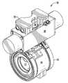
- FIG. 1is an exemplary embodiment of a valve package.
- FIG. 2is a baseline signature of the operation of a valve package.
- FIG. 3is a baseline signature of the operation of a valve package taken in-line with process flow in accordance with the present invention.
- a valve package 10typically includes a process valve 15 , actuator 20 and controller 25 .
- Process valve 15is installed along the longitudinal axis within a process pipeline (not shown) to allow, restrict or prevent process media flowing through the valve.
- Valve 15includes a housing 16 through which a flow passage 17 is disposed to allow process media to flow through the valve.
- Actuator 20is mounted on valve 15 and is typically pneumatically actuated, but may also be electric or hydraulic.
- Actuator 20includes an output shaft that is connected to the valve stem. The output shaft either rotates or lifts upward (depending on the valve type) to provide the necessary torque to turn or lift the valve stem to open or close the valve.
- Controller 25is usually mounted on the actuator and is configured to control the actuator based on various input signals. Controller 25 may also include a visual indicator 26 to display the position of valve 15 .
- the time it takes the valve to open and closewill depend on the type and size of the valve, the torque rating of the actuator, the process media flowing through the valve and the desired operating parameters. These dynamics of the valve package may be different when installed with process flowing through the system as compared to a standard or “bench” signature of the valve package.
- a valve 15 having a particular sizemay be configured with an actuator 20 appropriate for opening and closing the subject valve.
- the torque required from actuator 20 to open valve 15 with no process flowingmay be less than that required when process is flowing through the valve.
- an open and close signatureillustrating the time and pressure required to open and/or close valve 15 may be different in-line vs. out of line (or on a bench).
- FIG. 2illustrates an exemplary baseline signature of pressure vs. time for a valve package not installed within a process line.
- the profileincludes torque differential profile T, supply pressure profile S, valve position profile P, and exhaust profile E.
- Supply pressureis the amount of pressure supplied to the actuator.
- Exhaust pressureis the amount of pressure exiting the actuator.
- Positionindicates whether the valve is open, closed or somewhere in between as well as the time it takes to reach such a position.
- Differential pressureis the pressure to and from the actuator and provides information about the peak torque values. Peak torque relates to the amount of torque required when breaking the seal of the valve from its seat when opening the valve and when sufficiently engaging the seat of the valve when the valve is to be closed.
- the torque profile associated with a valve packageindicates that the valve is sized correctly if the profile falls within a predetermined safety margin.
- the torque profileidentifies the shear values associated with the particular valve and actuator shaft. For example, if the torque thrust associated with a particular torque profile is too high, this may indicate that the valve seal is corroding which may cause the shaft to stall during operation. If the torque is low or decreasing, this may indicate that the actuator is too large for the application imparting too much torque on the valve shaft which may eventually cause the shaft to snap.
- a baselineis used as a reference to compare operation of the valve assembly to determine degradation of the assembly within a process system.
- the valve position profile Pillustrates that the valve is in a closed position at time t c and begins to open (based on a received command to the controller) at about 0.255 sec.
- torque Tbegins to build as the valve is removed from its seat referred to as the peak torque T p which, in this example, is about 17 psi (g).
- the open supply pressure profile Sdecreases slightly at time t T at around 75 psi (g) when the valve breaks away from its seat. Once the valve seal is broken from the seat, the torque required to continue moving the valve to a full open position drops at around 0.795 sec and continues relatively constant until the valve is fully open at time t o (about 2.28 sec).
- the torquebuilds again as the valve remains in its open position at pressure T open .
- the exhaustis at its highest when the valve is commanded to open but is still in its closed position and decreases during the opening process as most of the supply pressure is used to increase the torque to open the valve.
- the exhaust profile Edecreases again as the valve reaches its open position at time t o .
- the torque overhead indicated by reference T OHrepresents the additional torque available from the actuator associated with this particular valve package which is a combination of the size of the valve vs. the size of the actuator when a baseline is taken on the bench.
- FIG. 3illustrates an exemplary baseline signature associated with a valve package in accordance with the present invention.
- the baseline signaturerepresents the operation of the valve package shown in FIG. 2 , but after the package is installed in-line with process flowing through the valve.
- the valve position profile Pillustrates that the valve is in a closed position at time t c and begins to open (based on a received command to the controller) at about 0.255 sec.
- the differential torque profile Tindicates that the torque begins to build as the valve opens from about 0.255 sec to about 1.3 sec t T .
- the valveis removed from its seat at the peak torque T p at about 48 psi (g).
- the open supply pressure profile Sdecreases slightly at time t T at around 85 psi (g) when the valve breaks away from its seat.
- the torque required to continue moving the valve to a full open positiondrops at around 1.335 sec and continues relatively constant until the valve is fully open at time t o (about 2.55 sec).
- the torquebuilds again as the valve remains in its open position at pressure T open .
- the exhaustis at its highest when the valve is commanded to open but is still in its closed position and decreases during the opening process as most of the supply pressure is used to increase the torque to open the valve.
- the exhaust profile Edecreases again as the valve reaches its open position at time t o .
- the differences between the baseline signature taken from a valve package out of line ( FIG. 2 ) and the baseline signature taken from a valve package taken in-line ( FIG. 3 )can be seen, for example, by the differences in peak torque T p (17 psi (g) vs. 48 psi (g)) and the time it takes for the valve to reach its fully open position t o (2.28 sec vs. 2.55 sec).
- the torque overhead T OHis also less in-line ( FIG. 3 ) than the torque overhead T OH from the baseline in FIG. 2 . In other words, it took a greater amount of torque to break the valve away from its seat when measured in-line vs. when the baseline was taken on the bench.
- a signatureis created which is compared to the dynamic baseline signature to determine if the valve package is within known operating tolerances.
- the number of operating signatures stored in memorymay vary by application. For example, operating signatures may be stored in memory based on a first in first out process depending on the type of application and memory size. However, if a particular operating signature triggers an alarm, that signature is locked in memory with a date and time stamp and treated by the user accordingly.
- the peak torque value T pwhich in this case is approximately half the maximum pressure, is also used to identify operational variations for alarm purposes.
- a usermay select a deviation zone around T p referenced as area A in FIG. 3 to determine acceptable parameters during valve operation.
- a hysteresis profilemay be created around deviation zone A which is used as a basis to trigger alarm activity.
- alarmsmay be triggered when the differential pressure changes outside of area A to indicate degradation of the valve package. For example, if the pressure required to break the seal when opening the valve increases outside deviation zone A, an alarm may sound alerting the user to possible operation failure. If the pressure required to break the seal when opening the valve decreases which falls outside deviation zone A, an alarm may sound alerting the user to possible operation failure.
- the percent deviation from T pis user defined and based on the type of valve employed and process media used.
- a dynamic baseline signaturemay be developed after N operating valve cycles. This may be done to capture process dynamics in-line after a defined Break-In period (cycle count) for a new valve assembly. A rolling average of the supply pressure taken from installation through the N th cycle is used to determine the Nominal Supply Pressure. Any alarms referenced above may be prohibited from triggering until after the Nth cycle to accommodate changes in operating characteristics of the valve package within the process environment during Break-In.
- a baseline signature associated with a valve package taken in-linea more accurate reference signature is captured. This leads to better monitoring of the valve package which avoids unnecessary maintenance costs and process interruptions.
- operation signaturesmay be used as a diagnostic tool to determine valve and actuator sizing and operation degradation.
- Both the baseline and operating signatures for each of the parametersare determined by a particular data scan rate in order to provide a graphical representation of the operation of the valve.
- a valve V 1undergoes a stroke from closed to an open position, it may take time t 1 to complete the stroke. This time t 1 is dependent on a number of variables including the size of valve V 1 , the size of the actuator and the process media flowing through. However, a smaller valve V 2 and actuator package may take time t 2 to complete a full stroke where t 1 >t 2 .
- the scan rate for valve V 2must be greater than the scan rate for valve V 1 because valve V 2 takes less time to complete a stroke.
- the method in accordance with the present inventionutilizes a look-up table to determine the sampling rates for a particular valve package based on the time it takes for the valve to complete a stroke during calibration. This is done while the valve is in-line. For example, if it takes 10 sec for a valve to open, the sampling rate for data collection may be every 50 msec. In addition, the sampling rate may be different where it takes the valve different times to open vs. close. Thus, one sampling rate may be associated with an open stroke and a different sampling rate may be associated with a close stroke for the same valve. In this manner, a method is utilized to capture dynamic reference characteristics of a valve package in-line with process flowing through the valve.
Landscapes
- Engineering & Computer Science (AREA)
- General Engineering & Computer Science (AREA)
- Mechanical Engineering (AREA)
- Indication Of The Valve Opening Or Closing Status (AREA)
Abstract
Description
Claims (20)
Priority Applications (1)
| Application Number | Priority Date | Filing Date | Title |
|---|---|---|---|
| US12/236,680US8265794B2 (en) | 2007-10-01 | 2008-09-24 | Knowledge based valve control method |
Applications Claiming Priority (2)
| Application Number | Priority Date | Filing Date | Title |
|---|---|---|---|
| US97662507P | 2007-10-01 | 2007-10-01 | |
| US12/236,680US8265794B2 (en) | 2007-10-01 | 2008-09-24 | Knowledge based valve control method |
Publications (2)
| Publication Number | Publication Date |
|---|---|
| US20090088906A1 US20090088906A1 (en) | 2009-04-02 |
| US8265794B2true US8265794B2 (en) | 2012-09-11 |
Family
ID=40509291
Family Applications (1)
| Application Number | Title | Priority Date | Filing Date |
|---|---|---|---|
| US12/236,680Expired - Fee RelatedUS8265794B2 (en) | 2007-10-01 | 2008-09-24 | Knowledge based valve control method |
Country Status (5)
| Country | Link |
|---|---|
| US (1) | US8265794B2 (en) |
| EP (1) | EP2193347B1 (en) |
| CN (1) | CN101815932B (en) |
| BR (1) | BRPI0817912A2 (en) |
| WO (1) | WO2009045848A1 (en) |
Cited By (17)
| Publication number | Priority date | Publication date | Assignee | Title |
|---|---|---|---|---|
| US20130291971A1 (en)* | 2012-05-04 | 2013-11-07 | General Electric Company | Custody transfer system and method for gas fuel |
| US20140069508A1 (en)* | 2012-09-07 | 2014-03-13 | Leo Minervini | Virtual Limit Switch |
| US9074770B2 (en) | 2011-12-15 | 2015-07-07 | Honeywell International Inc. | Gas valve with electronic valve proving system |
| US9557059B2 (en) | 2011-12-15 | 2017-01-31 | Honeywell International Inc | Gas valve with communication link |
| US9645584B2 (en) | 2014-09-17 | 2017-05-09 | Honeywell International Inc. | Gas valve with electronic health monitoring |
| US9657946B2 (en) | 2012-09-15 | 2017-05-23 | Honeywell International Inc. | Burner control system |
| US9683674B2 (en) | 2013-10-29 | 2017-06-20 | Honeywell Technologies Sarl | Regulating device |
| US9835265B2 (en) | 2011-12-15 | 2017-12-05 | Honeywell International Inc. | Valve with actuator diagnostics |
| US9846440B2 (en) | 2011-12-15 | 2017-12-19 | Honeywell International Inc. | Valve controller configured to estimate fuel comsumption |
| US9851103B2 (en) | 2011-12-15 | 2017-12-26 | Honeywell International Inc. | Gas valve with overpressure diagnostics |
| US9995486B2 (en) | 2011-12-15 | 2018-06-12 | Honeywell International Inc. | Gas valve with high/low gas pressure detection |
| US10422531B2 (en) | 2012-09-15 | 2019-09-24 | Honeywell International Inc. | System and approach for controlling a combustion chamber |
| US10503181B2 (en) | 2016-01-13 | 2019-12-10 | Honeywell International Inc. | Pressure regulator |
| US20190383422A1 (en)* | 2018-06-19 | 2019-12-19 | Samson Aktiengesellschaft | Detecting inadequate valve seat integrity of a control valve |
| US10564062B2 (en) | 2016-10-19 | 2020-02-18 | Honeywell International Inc. | Human-machine interface for gas valve |
| US10697815B2 (en) | 2018-06-09 | 2020-06-30 | Honeywell International Inc. | System and methods for mitigating condensation in a sensor module |
| US11073281B2 (en) | 2017-12-29 | 2021-07-27 | Honeywell International Inc. | Closed-loop programming and control of a combustion appliance |
Families Citing this family (11)
| Publication number | Priority date | Publication date | Assignee | Title |
|---|---|---|---|---|
| US8467907B2 (en)* | 2009-01-17 | 2013-06-18 | Certus Process Solutions | Automated valve with self-contained valve actuator system |
| GB2480423A (en)* | 2010-03-15 | 2011-11-23 | Jena Rotary Technolgy Ltd | Valve system |
| US8839680B2 (en)* | 2012-09-19 | 2014-09-23 | Fisher Controls International Llc | Methods and apparatus for estimating a condition of a seal of a rotary valve |
| TWI611127B (en)* | 2013-07-15 | 2018-01-11 | Jdv Control Valves Co Ltd | Intelligent valve control method |
| US9303785B2 (en) | 2013-08-02 | 2016-04-05 | Jdv Control Valves Co., Ltd | Method for controlling valve apparatus |
| RU2673031C1 (en)* | 2013-11-12 | 2018-11-21 | АБ Сомас Вентилер | Ball member for a valve assembly, ball valve assembly having a ball member and method for controlling the temperature of a ball member |
| DE102015210208A1 (en)* | 2015-06-02 | 2016-12-08 | Gemü Gebr. Müller Apparatebau Gmbh & Co. Kommanditgesellschaft | Method for determining a state variable of a valve diaphragm of an electronically controlled and motor-driven diaphragm valve, and diaphragm valve system |
| EP3592989B1 (en) | 2017-03-07 | 2022-01-12 | Asco, L.P. | A device and method for anticipating failure in a solenoid valve for a manifold assembly |
| US10711907B2 (en)* | 2017-11-07 | 2020-07-14 | Black Diamond Engineering, Inc. | Line replaceable control valve positioner/controller system |
| RU2686257C1 (en)* | 2018-04-27 | 2019-04-24 | Ационерное общество "РОТЕК" (АО "РОТЕК") | Method and system for remote identification and prediction of development of emerging defects of objects |
| TWI672461B (en)* | 2018-08-01 | 2019-09-21 | 光旴科技股份有限公司 | Full port ball valve maintenance warning device |
Citations (62)
| Publication number | Priority date | Publication date | Assignee | Title |
|---|---|---|---|---|
| US4037598A (en)* | 1974-08-12 | 1977-07-26 | Ivac Corporation | Method and apparatus for fluid flow control |
| US4417312A (en)* | 1981-06-08 | 1983-11-22 | Worcester Controls Corporation | Electronic controller for valve actuators |
| US4590576A (en)* | 1984-07-26 | 1986-05-20 | Mark Controls Corporation | Control system for flow control valves |
| US4879662A (en)* | 1988-03-11 | 1989-11-07 | Sundstrand Corporation | Fluid flow self calibration scheme |
| US4896101A (en)* | 1986-12-03 | 1990-01-23 | Cobb Harold R W | Method for monitoring, recording, and evaluating valve operating trends |
| US5124934A (en)* | 1989-03-03 | 1992-06-23 | Inax Corporation | Constant feed water device |
| US5142483A (en)* | 1990-04-24 | 1992-08-25 | Caltechnix Corporation | Pressure regulating system for positive shut-off pressure controller |
| US5518015A (en)* | 1994-09-30 | 1996-05-21 | Gas Research Institute | Automatic calibrating electrically controlled diaphragm valve actuators and methods for their calibration |
| US5995909A (en)* | 1995-05-05 | 1999-11-30 | Nordson Corporation | Method of compensating for changes in flow characteristics of a dispensed fluid |
| US6047220A (en)* | 1996-12-31 | 2000-04-04 | Rosemount Inc. | Device in a process system for validating a control signal from a field device |
| US6260004B1 (en)* | 1997-12-31 | 2001-07-10 | Innovation Management Group, Inc. | Method and apparatus for diagnosing a pump system |
| US6272401B1 (en)* | 1997-07-23 | 2001-08-07 | Dresser Industries, Inc. | Valve positioner system |
| US20010035512A1 (en)* | 2000-04-07 | 2001-11-01 | Messer Jeffrey M. | Environmentally friendly electro-pneumatic positioner |
| US6356811B1 (en)* | 1998-10-13 | 2002-03-12 | Honeywell Measurex Devron Inc. | Control system for pneumatic actuators |
| US6370448B1 (en)* | 1997-10-13 | 2002-04-09 | Rosemount Inc. | Communication technique for field devices in industrial processes |
| US20020198668A1 (en)* | 2001-04-24 | 2002-12-26 | Lull John M. | System and method for a mass flow controller |
| US6519938B1 (en)* | 1998-12-22 | 2003-02-18 | Coltec Industries Inc. | Recording and controlling pneumatic profiles |
| US6564824B2 (en)* | 2001-04-13 | 2003-05-20 | Flowmatrix, Inc. | Mass flow meter systems and methods |
| US6655408B2 (en)* | 2001-06-13 | 2003-12-02 | Applied Materials, Inc. | Tunable ramp rate circuit for a mass flow controller |
| US6725167B2 (en)* | 2002-01-16 | 2004-04-20 | Fisher Controls International Llc | Flow measurement module and method |
| US6745107B1 (en)* | 2000-06-30 | 2004-06-01 | Honeywell Inc. | System and method for non-invasive diagnostic testing of control valves |
| US20040204794A1 (en)* | 2001-12-28 | 2004-10-14 | Tadahiro Ohmi | Advance pressure type flow control device |
| US6810308B2 (en)* | 2002-06-24 | 2004-10-26 | Mks Instruments, Inc. | Apparatus and method for mass flow controller with network access to diagnostics |
| US6810906B2 (en)* | 2002-07-30 | 2004-11-02 | Mitsubishi Heavy Industries, Ltd. | Flow control device |
| US6820631B2 (en)* | 2001-11-23 | 2004-11-23 | Siemens Aktiengesellschaft | Method for the continuous control of a position of a control valve |
| US20050059926A1 (en)* | 2003-09-16 | 2005-03-17 | Therafuse, Inc. | Compensating liquid delivery system and method |
| US6895287B2 (en)* | 2002-05-21 | 2005-05-17 | Yamatake Corporation | Control method and control apparatus |
| US6917858B2 (en)* | 2003-08-29 | 2005-07-12 | Dresser, Inc. | Fluid regulation |
| US20050182525A1 (en)* | 2004-02-13 | 2005-08-18 | Marc Laverdiere | System and method of controlling fluid flow |
| US20050182524A1 (en)* | 2004-02-12 | 2005-08-18 | Brodeur Craig L. | System and method for flow monitoring and control |
| US7004191B2 (en)* | 2002-06-24 | 2006-02-28 | Mks Instruments, Inc. | Apparatus and method for mass flow controller with embedded web server |
| US7018800B2 (en)* | 2003-08-07 | 2006-03-28 | Rosemount Inc. | Process device with quiescent current diagnostics |
| US7069944B2 (en)* | 2003-02-24 | 2006-07-04 | Smc Corporation | Flow rate control device |
| US7089086B2 (en)* | 2003-02-14 | 2006-08-08 | Dresser, Inc. | Method, system and storage medium for performing online valve diagnostics |
| US7111614B1 (en)* | 2005-08-29 | 2006-09-26 | Caterpillar Inc. | Single fluid injector with rate shaping capability |
| US20060272710A1 (en) | 2004-04-05 | 2006-12-07 | Westlock Controls Corporation | Device and method for pneumatic valve control |
| US20070016333A1 (en)* | 2005-07-12 | 2007-01-18 | Edwards Grant B | Method and apparatus for controlling the valve position of a variable orifice flow meter |
| US20070068225A1 (en)* | 2005-09-29 | 2007-03-29 | Brown Gregory C | Leak detector for process valve |
| US7264017B2 (en)* | 2005-05-12 | 2007-09-04 | Honeywell International, Inc. | Dual-actuator aircraft environmental control system valve |
| US7272512B2 (en)* | 2003-03-26 | 2007-09-18 | Celerity, Inc. | Flow sensor signal conversion |
| US20070225870A1 (en)* | 2006-03-21 | 2007-09-27 | Mks Instruments, Inc. | Pressure control system with optimized performance |
| US20070262029A1 (en)* | 2006-01-09 | 2007-11-15 | Takashi Yoshida | Actuated pressure control valve assembly and method |
| US20080004836A1 (en)* | 2006-06-30 | 2008-01-03 | Fisher Controls International | Computerized evaluation of valve signature graphs |
| US20080009978A1 (en)* | 2006-07-05 | 2008-01-10 | Smirnov Alexei V | Multi-mode control algorithm |
| US20080091306A1 (en)* | 2002-06-24 | 2008-04-17 | Mks Instruments, Inc. | Apparatus and method for pressure fluctuation insensitive mass flow control |
| US20080140260A1 (en)* | 2006-12-07 | 2008-06-12 | Junhua Ding | Controller gain scheduling for mass flow controllers |
| US20080154436A1 (en)* | 2006-12-21 | 2008-06-26 | Abb Patent Gmbh | Control device for a pneumatically operated actuator |
| US7403826B2 (en)* | 2004-12-01 | 2008-07-22 | Canadian Space Agency | Method and system for torque/force control of hydraulic actuators |
| US20080264498A1 (en)* | 2005-11-22 | 2008-10-30 | Norgren, Inc. | Valve with Sensor |
| US20080294293A1 (en)* | 2004-08-31 | 2008-11-27 | Asahi Organic Chemicals Industry Co., Ltd. | Fluid Controller |
| US7512460B2 (en)* | 2006-02-27 | 2009-03-31 | Cnh America Llc | Valve calibration routine |
| US7539560B2 (en)* | 2007-01-05 | 2009-05-26 | Dresser, Inc. | Control valve and positioner diagnostics |
| US7559197B2 (en)* | 2005-08-31 | 2009-07-14 | Caterpillar Inc. | Combiner valve control system and method |
| US20090312876A1 (en)* | 2006-10-03 | 2009-12-17 | Horiba Stec, Co., Ltd. | Mass flow controller |
| US20090326719A1 (en)* | 2005-09-01 | 2009-12-31 | Fujikin Incorporated | Method for detecting abnormality in fluid supply line using fluid control apparatus with pressure sensor |
| US7720574B1 (en)* | 2001-06-20 | 2010-05-18 | Curtis Roys | Fluid flow monitor and control system |
| US7740024B2 (en)* | 2004-02-12 | 2010-06-22 | Entegris, Inc. | System and method for flow monitoring and control |
| US7918238B2 (en)* | 2004-06-21 | 2011-04-05 | Hitachi Metals, Ltd. | Flow controller and its regulation method |
| US7925385B2 (en)* | 2006-03-08 | 2011-04-12 | Itt Manufacturing Enterprises, Inc | Method for optimizing valve position and pump speed in a PID control valve system without the use of external signals |
| US8062257B2 (en)* | 1998-10-29 | 2011-11-22 | Medtronic Minimed, Inc. | Method and apparatus for detecting occlusions in an ambulatory infusion pump |
| US8082946B2 (en)* | 2002-07-19 | 2011-12-27 | Entegris, Inc. | Liquid flow controller and precision dispense apparatus and system |
| US8112182B2 (en)* | 2004-02-03 | 2012-02-07 | Hitachi Metals, Ltd. | Mass flow rate-controlling apparatus |
Family Cites Families (3)
| Publication number | Priority date | Publication date | Assignee | Title |
|---|---|---|---|---|
| US5687098A (en)* | 1995-10-30 | 1997-11-11 | Fisher Controls International, Inc. | Device data acquisition |
| CN1187438A (en)* | 1996-12-23 | 1998-07-15 | 西屋气刹车公司 | Electro-pneumatic valve control |
| CN101133271B (en)* | 2005-03-01 | 2010-05-26 | 藤仓橡胶工业株式会社 | Normally closed valve with micro-flow regulating device |
- 2008
- 2008-09-24USUS12/236,680patent/US8265794B2/ennot_activeExpired - Fee Related
- 2008-09-25BRBRPI0817912patent/BRPI0817912A2/ennot_activeApplication Discontinuation
- 2008-09-25CNCN200880109991XApatent/CN101815932B/ennot_activeExpired - Fee Related
- 2008-09-25WOPCT/US2008/077676patent/WO2009045848A1/enactiveApplication Filing
- 2008-09-25EPEP08834913.9Apatent/EP2193347B1/ennot_activeNot-in-force
Patent Citations (86)
| Publication number | Priority date | Publication date | Assignee | Title |
|---|---|---|---|---|
| US4037598A (en)* | 1974-08-12 | 1977-07-26 | Ivac Corporation | Method and apparatus for fluid flow control |
| US4417312A (en)* | 1981-06-08 | 1983-11-22 | Worcester Controls Corporation | Electronic controller for valve actuators |
| US4590576A (en)* | 1984-07-26 | 1986-05-20 | Mark Controls Corporation | Control system for flow control valves |
| US4896101A (en)* | 1986-12-03 | 1990-01-23 | Cobb Harold R W | Method for monitoring, recording, and evaluating valve operating trends |
| US4879662A (en)* | 1988-03-11 | 1989-11-07 | Sundstrand Corporation | Fluid flow self calibration scheme |
| US5124934A (en)* | 1989-03-03 | 1992-06-23 | Inax Corporation | Constant feed water device |
| US5142483A (en)* | 1990-04-24 | 1992-08-25 | Caltechnix Corporation | Pressure regulating system for positive shut-off pressure controller |
| US5518015A (en)* | 1994-09-30 | 1996-05-21 | Gas Research Institute | Automatic calibrating electrically controlled diaphragm valve actuators and methods for their calibration |
| US5711507A (en)* | 1994-09-30 | 1998-01-27 | Gas Research Institute | Automatic calibrating electrically controlled diaphragm valve actuators and methods for their calibration |
| US5995909A (en)* | 1995-05-05 | 1999-11-30 | Nordson Corporation | Method of compensating for changes in flow characteristics of a dispensed fluid |
| US6047220A (en)* | 1996-12-31 | 2000-04-04 | Rosemount Inc. | Device in a process system for validating a control signal from a field device |
| US6272401B1 (en)* | 1997-07-23 | 2001-08-07 | Dresser Industries, Inc. | Valve positioner system |
| US20010037159A1 (en)* | 1997-07-23 | 2001-11-01 | Henry Boger | Valve positioner system |
| US20010037670A1 (en) | 1997-07-23 | 2001-11-08 | Henry Boger | Valve positioner system |
| US6370448B1 (en)* | 1997-10-13 | 2002-04-09 | Rosemount Inc. | Communication technique for field devices in industrial processes |
| US6260004B1 (en)* | 1997-12-31 | 2001-07-10 | Innovation Management Group, Inc. | Method and apparatus for diagnosing a pump system |
| US6356811B1 (en)* | 1998-10-13 | 2002-03-12 | Honeywell Measurex Devron Inc. | Control system for pneumatic actuators |
| US8062257B2 (en)* | 1998-10-29 | 2011-11-22 | Medtronic Minimed, Inc. | Method and apparatus for detecting occlusions in an ambulatory infusion pump |
| US6519938B1 (en)* | 1998-12-22 | 2003-02-18 | Coltec Industries Inc. | Recording and controlling pneumatic profiles |
| US20010035512A1 (en)* | 2000-04-07 | 2001-11-01 | Messer Jeffrey M. | Environmentally friendly electro-pneumatic positioner |
| US6745107B1 (en)* | 2000-06-30 | 2004-06-01 | Honeywell Inc. | System and method for non-invasive diagnostic testing of control valves |
| US6564824B2 (en)* | 2001-04-13 | 2003-05-20 | Flowmatrix, Inc. | Mass flow meter systems and methods |
| US6564825B2 (en)* | 2001-04-13 | 2003-05-20 | Flowmatrix, Inc. | Mass flow meter systems and methods |
| US7114511B2 (en)* | 2001-04-24 | 2006-10-03 | Celerity Group, Inc. | System and method for a mass flow controller |
| US6962164B2 (en)* | 2001-04-24 | 2005-11-08 | Celerity Group, Inc. | System and method for a mass flow controller |
| US7231931B2 (en)* | 2001-04-24 | 2007-06-19 | Celerity, Inc. | System and method for a mass flow controller |
| US7380564B2 (en)* | 2001-04-24 | 2008-06-03 | Celerity, Inc. | System and method for a mass flow controller |
| US20020198668A1 (en)* | 2001-04-24 | 2002-12-26 | Lull John M. | System and method for a mass flow controller |
| US6655408B2 (en)* | 2001-06-13 | 2003-12-02 | Applied Materials, Inc. | Tunable ramp rate circuit for a mass flow controller |
| US7720574B1 (en)* | 2001-06-20 | 2010-05-18 | Curtis Roys | Fluid flow monitor and control system |
| US6820631B2 (en)* | 2001-11-23 | 2004-11-23 | Siemens Aktiengesellschaft | Method for the continuous control of a position of a control valve |
| US20040204794A1 (en)* | 2001-12-28 | 2004-10-14 | Tadahiro Ohmi | Advance pressure type flow control device |
| US6725167B2 (en)* | 2002-01-16 | 2004-04-20 | Fisher Controls International Llc | Flow measurement module and method |
| US6895287B2 (en)* | 2002-05-21 | 2005-05-17 | Yamatake Corporation | Control method and control apparatus |
| US20080091306A1 (en)* | 2002-06-24 | 2008-04-17 | Mks Instruments, Inc. | Apparatus and method for pressure fluctuation insensitive mass flow control |
| US20100324743A1 (en)* | 2002-06-24 | 2010-12-23 | Mks Instruments, Inc. | Apparatus and method for pressure fluctuation insensitive mass flow control |
| US7004191B2 (en)* | 2002-06-24 | 2006-02-28 | Mks Instruments, Inc. | Apparatus and method for mass flow controller with embedded web server |
| US8150553B2 (en)* | 2002-06-24 | 2012-04-03 | Mks Instruments, Inc. | Apparatus and method for pressure fluctuation insensitive mass flow control |
| US7809473B2 (en)* | 2002-06-24 | 2010-10-05 | Mks Instruments, Inc. | Apparatus and method for pressure fluctuation insensitive mass flow control |
| US6810308B2 (en)* | 2002-06-24 | 2004-10-26 | Mks Instruments, Inc. | Apparatus and method for mass flow controller with network access to diagnostics |
| US8082946B2 (en)* | 2002-07-19 | 2011-12-27 | Entegris, Inc. | Liquid flow controller and precision dispense apparatus and system |
| US6810906B2 (en)* | 2002-07-30 | 2004-11-02 | Mitsubishi Heavy Industries, Ltd. | Flow control device |
| US7089086B2 (en)* | 2003-02-14 | 2006-08-08 | Dresser, Inc. | Method, system and storage medium for performing online valve diagnostics |
| US7069944B2 (en)* | 2003-02-24 | 2006-07-04 | Smc Corporation | Flow rate control device |
| US7272512B2 (en)* | 2003-03-26 | 2007-09-18 | Celerity, Inc. | Flow sensor signal conversion |
| US7018800B2 (en)* | 2003-08-07 | 2006-03-28 | Rosemount Inc. | Process device with quiescent current diagnostics |
| US6917858B2 (en)* | 2003-08-29 | 2005-07-12 | Dresser, Inc. | Fluid regulation |
| US20050059926A1 (en)* | 2003-09-16 | 2005-03-17 | Therafuse, Inc. | Compensating liquid delivery system and method |
| US8112182B2 (en)* | 2004-02-03 | 2012-02-07 | Hitachi Metals, Ltd. | Mass flow rate-controlling apparatus |
| US7740024B2 (en)* | 2004-02-12 | 2010-06-22 | Entegris, Inc. | System and method for flow monitoring and control |
| US20060052904A1 (en)* | 2004-02-12 | 2006-03-09 | Brodeur Craig L | System and method for flow monitoring and control |
| US6973375B2 (en)* | 2004-02-12 | 2005-12-06 | Mykrolis Corporation | System and method for flow monitoring and control |
| US8015995B2 (en)* | 2004-02-12 | 2011-09-13 | Entegris, Inc. | System and method for flow monitoring and control |
| US20050182524A1 (en)* | 2004-02-12 | 2005-08-18 | Brodeur Craig L. | System and method for flow monitoring and control |
| US20050182525A1 (en)* | 2004-02-13 | 2005-08-18 | Marc Laverdiere | System and method of controlling fluid flow |
| US7317971B2 (en)* | 2004-02-13 | 2008-01-08 | Entegris, Inc. | System for controlling fluid flow based on a valve break point |
| US8082066B2 (en)* | 2004-02-13 | 2011-12-20 | Entegris, Inc. | System for controlling valve fluid flow based on rate of change of close rate acceleration |
| US20060276935A1 (en)* | 2004-02-13 | 2006-12-07 | Marc Laverdiere | System for controlling fluid flow |
| US20060272710A1 (en) | 2004-04-05 | 2006-12-07 | Westlock Controls Corporation | Device and method for pneumatic valve control |
| US7918238B2 (en)* | 2004-06-21 | 2011-04-05 | Hitachi Metals, Ltd. | Flow controller and its regulation method |
| US20080294293A1 (en)* | 2004-08-31 | 2008-11-27 | Asahi Organic Chemicals Industry Co., Ltd. | Fluid Controller |
| US7403826B2 (en)* | 2004-12-01 | 2008-07-22 | Canadian Space Agency | Method and system for torque/force control of hydraulic actuators |
| US7264017B2 (en)* | 2005-05-12 | 2007-09-04 | Honeywell International, Inc. | Dual-actuator aircraft environmental control system valve |
| US20070016333A1 (en)* | 2005-07-12 | 2007-01-18 | Edwards Grant B | Method and apparatus for controlling the valve position of a variable orifice flow meter |
| US7111614B1 (en)* | 2005-08-29 | 2006-09-26 | Caterpillar Inc. | Single fluid injector with rate shaping capability |
| US7559197B2 (en)* | 2005-08-31 | 2009-07-14 | Caterpillar Inc. | Combiner valve control system and method |
| US7945414B2 (en)* | 2005-09-01 | 2011-05-17 | Fujikin Incorporated | Method for detecting abnormality in fluid supply line using fluid control apparatus with pressure sensor |
| US20090326719A1 (en)* | 2005-09-01 | 2009-12-31 | Fujikin Incorporated | Method for detecting abnormality in fluid supply line using fluid control apparatus with pressure sensor |
| US7940189B2 (en)* | 2005-09-29 | 2011-05-10 | Rosemount Inc. | Leak detector for process valve |
| US20070068225A1 (en)* | 2005-09-29 | 2007-03-29 | Brown Gregory C | Leak detector for process valve |
| US20090303057A1 (en)* | 2005-09-29 | 2009-12-10 | Brown Gregory C | Leak detector for process valve |
| US20080264498A1 (en)* | 2005-11-22 | 2008-10-30 | Norgren, Inc. | Valve with Sensor |
| US20070262029A1 (en)* | 2006-01-09 | 2007-11-15 | Takashi Yoshida | Actuated pressure control valve assembly and method |
| US7512460B2 (en)* | 2006-02-27 | 2009-03-31 | Cnh America Llc | Valve calibration routine |
| US7925385B2 (en)* | 2006-03-08 | 2011-04-12 | Itt Manufacturing Enterprises, Inc | Method for optimizing valve position and pump speed in a PID control valve system without the use of external signals |
| US20070225870A1 (en)* | 2006-03-21 | 2007-09-27 | Mks Instruments, Inc. | Pressure control system with optimized performance |
| US20080004836A1 (en)* | 2006-06-30 | 2008-01-03 | Fisher Controls International | Computerized evaluation of valve signature graphs |
| US20080009978A1 (en)* | 2006-07-05 | 2008-01-10 | Smirnov Alexei V | Multi-mode control algorithm |
| US20090312876A1 (en)* | 2006-10-03 | 2009-12-17 | Horiba Stec, Co., Ltd. | Mass flow controller |
| US7881829B2 (en)* | 2006-10-03 | 2011-02-01 | Horiba Stec Co., Ltd. | Mass flow controller |
| US20080140260A1 (en)* | 2006-12-07 | 2008-06-12 | Junhua Ding | Controller gain scheduling for mass flow controllers |
| US8079383B2 (en)* | 2006-12-07 | 2011-12-20 | Mks Instruments, Inc. | Controller gain scheduling for mass flow controllers |
| US20080154436A1 (en)* | 2006-12-21 | 2008-06-26 | Abb Patent Gmbh | Control device for a pneumatically operated actuator |
| US7925386B2 (en)* | 2006-12-21 | 2011-04-12 | Abb Ag | Control device for a pneumatically operated actuator |
| US7890216B2 (en)* | 2007-01-05 | 2011-02-15 | Dresser, Inc. | Control valve and positioner diagnostics |
| US7539560B2 (en)* | 2007-01-05 | 2009-05-26 | Dresser, Inc. | Control valve and positioner diagnostics |
Non-Patent Citations (4)
| Title |
|---|
| Atmanand, M.A. and Konnur, M.S., "A Novel Method of Using a Control Valve for Measurement and Control of Flow", Dec. 1999, IEEE Transactions on Instrumentation and Measurement, vol. 48, No. 6.* |
| Poley, R., "DSP Control of Electro-Hydraulic Servo Actuators", Jan. 2005, Texas Instruments, Application Report-SPRAA76.* |
| Poley, R., "DSP Control of Electro-Hydraulic Servo Actuators", Jan. 2005, Texas Instruments, Application Report—SPRAA76.* |
| Wu, D., Burton, R., Schoenau, G. and Bitner, D., "Analysis of a Pressure-Compensated Flow Control Valve", Mar. 2007, Journal of Dynamic Systems, Measurement and Control, vol. 129.* |
Cited By (25)
| Publication number | Priority date | Publication date | Assignee | Title |
|---|---|---|---|---|
| US9835265B2 (en) | 2011-12-15 | 2017-12-05 | Honeywell International Inc. | Valve with actuator diagnostics |
| US10851993B2 (en) | 2011-12-15 | 2020-12-01 | Honeywell International Inc. | Gas valve with overpressure diagnostics |
| US9074770B2 (en) | 2011-12-15 | 2015-07-07 | Honeywell International Inc. | Gas valve with electronic valve proving system |
| US9995486B2 (en) | 2011-12-15 | 2018-06-12 | Honeywell International Inc. | Gas valve with high/low gas pressure detection |
| US10697632B2 (en) | 2011-12-15 | 2020-06-30 | Honeywell International Inc. | Gas valve with communication link |
| US9557059B2 (en) | 2011-12-15 | 2017-01-31 | Honeywell International Inc | Gas valve with communication link |
| US9851103B2 (en) | 2011-12-15 | 2017-12-26 | Honeywell International Inc. | Gas valve with overpressure diagnostics |
| US9846440B2 (en) | 2011-12-15 | 2017-12-19 | Honeywell International Inc. | Valve controller configured to estimate fuel comsumption |
| US9175810B2 (en)* | 2012-05-04 | 2015-11-03 | General Electric Company | Custody transfer system and method for gas fuel |
| US20130291971A1 (en)* | 2012-05-04 | 2013-11-07 | General Electric Company | Custody transfer system and method for gas fuel |
| US9133959B2 (en)* | 2012-09-07 | 2015-09-15 | Pentair Flow Services Ag | Virtual limit switch |
| US20140069508A1 (en)* | 2012-09-07 | 2014-03-13 | Leo Minervini | Virtual Limit Switch |
| US9657946B2 (en) | 2012-09-15 | 2017-05-23 | Honeywell International Inc. | Burner control system |
| US11421875B2 (en) | 2012-09-15 | 2022-08-23 | Honeywell International Inc. | Burner control system |
| US10422531B2 (en) | 2012-09-15 | 2019-09-24 | Honeywell International Inc. | System and approach for controlling a combustion chamber |
| US9683674B2 (en) | 2013-10-29 | 2017-06-20 | Honeywell Technologies Sarl | Regulating device |
| US10215291B2 (en) | 2013-10-29 | 2019-02-26 | Honeywell International Inc. | Regulating device |
| US9645584B2 (en) | 2014-09-17 | 2017-05-09 | Honeywell International Inc. | Gas valve with electronic health monitoring |
| US10203049B2 (en) | 2014-09-17 | 2019-02-12 | Honeywell International Inc. | Gas valve with electronic health monitoring |
| US10503181B2 (en) | 2016-01-13 | 2019-12-10 | Honeywell International Inc. | Pressure regulator |
| US10564062B2 (en) | 2016-10-19 | 2020-02-18 | Honeywell International Inc. | Human-machine interface for gas valve |
| US11073281B2 (en) | 2017-12-29 | 2021-07-27 | Honeywell International Inc. | Closed-loop programming and control of a combustion appliance |
| US10697815B2 (en) | 2018-06-09 | 2020-06-30 | Honeywell International Inc. | System and methods for mitigating condensation in a sensor module |
| US20190383422A1 (en)* | 2018-06-19 | 2019-12-19 | Samson Aktiengesellschaft | Detecting inadequate valve seat integrity of a control valve |
| US10851912B2 (en)* | 2018-06-19 | 2020-12-01 | Samson Aktiengesellschaft | Detecting inadequate valve seat integrity of a control valve |
Also Published As
| Publication number | Publication date |
|---|---|
| EP2193347B1 (en) | 2018-04-25 |
| WO2009045848A1 (en) | 2009-04-09 |
| EP2193347A4 (en) | 2011-11-30 |
| EP2193347A1 (en) | 2010-06-09 |
| BRPI0817912A2 (en) | 2015-04-07 |
| CN101815932A (en) | 2010-08-25 |
| US20090088906A1 (en) | 2009-04-02 |
| CN101815932B (en) | 2013-09-18 |
Similar Documents
| Publication | Publication Date | Title |
|---|---|---|
| US8265794B2 (en) | Knowledge based valve control method | |
| EP2843281B1 (en) | Diagnostic method for detecting control valve component failure | |
| US6382226B1 (en) | Method for detecting broken valve stem | |
| US7584643B2 (en) | Method for testing the functionality of an actuator, especially of an actuator of a safety valve | |
| US7539560B2 (en) | Control valve and positioner diagnostics | |
| KR101915638B1 (en) | Multi-channel valve control and self-diagnosis system | |
| KR20190012325A (en) | Intelligent control valve with safety function based on self-diagnosis function and control valve management system using it | |
| JPH11315955A (en) | Maintenance monitor system for steam turbine valve | |
| US20210254750A1 (en) | Diagnosis of possible causes of changes in a control valve | |
| KR102802553B1 (en) | Self Diagnostics Smart Remote Positioner | |
| Kiesbauer et al. | SAMSON | |
| Li et al. | A review of recent valve health monitoring and diagnosis methods |
Legal Events
| Date | Code | Title | Description |
|---|---|---|---|
| AS | Assignment | Owner name:WESTLOCK CONTROLS CORPORATION, NEW JERSEY Free format text:ASSIGNMENT OF ASSIGNORS INTEREST;ASSIGNORS:MINERVINI, LEO;MROZINSKI, DANIEL W.;REEL/FRAME:021578/0473 Effective date:20080923 | |
| STCF | Information on status: patent grant | Free format text:PATENTED CASE | |
| FPAY | Fee payment | Year of fee payment:4 | |
| AS | Assignment | Owner name:PENTAIR FLOW CONTROL AG, SWITZERLAND Free format text:ASSIGNMENT OF ASSIGNORS INTEREST;ASSIGNOR:WESTLOCK CONTROLS CORPORATION;REEL/FRAME:040512/0711 Effective date:20150329 | |
| AS | Assignment | Owner name:WESTLOCK CONTROLS CORPORATION, NEW JERSEY Free format text:ASSIGNMENT OF ASSIGNORS INTEREST;ASSIGNOR:PENTAIR FLOW CONTROL AG;REEL/FRAME:045317/0009 Effective date:20170428 | |
| FEPP | Fee payment procedure | Free format text:MAINTENANCE FEE REMINDER MAILED (ORIGINAL EVENT CODE: REM.); ENTITY STATUS OF PATENT OWNER: LARGE ENTITY | |
| LAPS | Lapse for failure to pay maintenance fees | Free format text:PATENT EXPIRED FOR FAILURE TO PAY MAINTENANCE FEES (ORIGINAL EVENT CODE: EXP.); ENTITY STATUS OF PATENT OWNER: LARGE ENTITY | |
| STCH | Information on status: patent discontinuation | Free format text:PATENT EXPIRED DUE TO NONPAYMENT OF MAINTENANCE FEES UNDER 37 CFR 1.362 | |
| FP | Lapsed due to failure to pay maintenance fee | Effective date:20200911 |