US8265728B2 - Automated method and system for the evaluation of disease and registration accuracy in the subtraction of temporally sequential medical images - Google Patents
Automated method and system for the evaluation of disease and registration accuracy in the subtraction of temporally sequential medical imagesDownload PDFInfo
- Publication number
- US8265728B2 US8265728B2US10/721,827US72182703AUS8265728B2US 8265728 B2US8265728 B2US 8265728B2US 72182703 AUS72182703 AUS 72182703AUS 8265728 B2US8265728 B2US 8265728B2
- Authority
- US
- United States
- Prior art keywords
- image
- subtraction
- images
- gray
- energy
- Prior art date
- Legal status (The legal status is an assumption and is not a legal conclusion. Google has not performed a legal analysis and makes no representation as to the accuracy of the status listed.)
- Expired - Fee Related, expires
Links
Images


Classifications
- A—HUMAN NECESSITIES
- A61—MEDICAL OR VETERINARY SCIENCE; HYGIENE
- A61B—DIAGNOSIS; SURGERY; IDENTIFICATION
- A61B6/00—Apparatus or devices for radiation diagnosis; Apparatus or devices for radiation diagnosis combined with radiation therapy equipment
- A61B6/48—Diagnostic techniques
- A61B6/482—Diagnostic techniques involving multiple energy imaging
- A—HUMAN NECESSITIES
- A61—MEDICAL OR VETERINARY SCIENCE; HYGIENE
- A61B—DIAGNOSIS; SURGERY; IDENTIFICATION
- A61B6/00—Apparatus or devices for radiation diagnosis; Apparatus or devices for radiation diagnosis combined with radiation therapy equipment
- A61B6/46—Arrangements for interfacing with the operator or the patient
- A61B6/461—Displaying means of special interest
- A61B6/463—Displaying means of special interest characterised by displaying multiple images or images and diagnostic data on one display
- G—PHYSICS
- G06—COMPUTING OR CALCULATING; COUNTING
- G06T—IMAGE DATA PROCESSING OR GENERATION, IN GENERAL
- G06T5/00—Image enhancement or restoration
- G06T5/50—Image enhancement or restoration using two or more images, e.g. averaging or subtraction
- G—PHYSICS
- G06—COMPUTING OR CALCULATING; COUNTING
- G06T—IMAGE DATA PROCESSING OR GENERATION, IN GENERAL
- G06T7/00—Image analysis
- G06T7/0002—Inspection of images, e.g. flaw detection
- G06T7/0012—Biomedical image inspection
- G—PHYSICS
- G06—COMPUTING OR CALCULATING; COUNTING
- G06T—IMAGE DATA PROCESSING OR GENERATION, IN GENERAL
- G06T7/00—Image analysis
- G06T7/30—Determination of transform parameters for the alignment of images, i.e. image registration
- G—PHYSICS
- G06—COMPUTING OR CALCULATING; COUNTING
- G06T—IMAGE DATA PROCESSING OR GENERATION, IN GENERAL
- G06T2207/00—Indexing scheme for image analysis or image enhancement
- G06T2207/30—Subject of image; Context of image processing
- G06T2207/30004—Biomedical image processing
- G06T2207/30061—Lung
Definitions
- a method, system, and computer program product for computer aided detection (CAD) of disease with a reduced false positive rateA method, system, and computer program product for computer aided detection (CAD) of disease with a reduced false positive rate.
- CADcomputer aided detection
- the present inventionalso generally relates to computerized techniques for automated analysis of digital images, for example, as disclosed in one or more of U.S. Pat. Nos. 4,839,807; 4,841,555; 4,851,984; 4,875,165; 4,907,156; 4,918,534; 5,072,384; 5,133,020; 5,150,292; 5,224,177; 5,289,374; 5,319,549; 5,343,390; 5,359,513; 5,452,367; 5,463,548; 5,537,485; 5,598,481; 5,622,171; 5,638,458; 5,657,362; 5,666,434; 5,668,888; 5,740,268; 5,832,103; 5,873,824; 5,881,124; 5,931,780; 5,974,165; 5,982,915; 5,984,870; 5,987,345; 6,011,862; 6,058,322; 6,067,373; 6,075,878
- Radiologistsroutinely compare multiple chest radiographs acquired from the same patient over time to facilitate a more complete understanding of changes in anatomy and pathology. Some of these comparisons are merely visual. Some involve comparing CAD results from a first image with CAD results from a later image, e.g., as taught by Roehrig et al. (PCT Publication WO 00/25255), the contents of which are incorporated herein by reference. Some comparisons involve the generation of temporally sequential images which are registered to construct a “temporal subtraction image.” This latter technique has proven to be a powerful technique for enhanced visualization of either subtle pathology or small changes in size of more obvious lesions, for example in radiographic chest images (1-14).
- Temporal subtraction imagesare not disease specific. Whereas most applications of computers as a diagnostic aid in radiology have been developed for a specific pathology such as lung nodules or emphysema, temporal subtraction images enhance a radiologist's ability to visualize a wide spectrum of disease. The only requirement is that changes in the size, shape, or density of the disease, as projected in the image plane, exist between the two studies. In conventional systems, once created as a visualization tool, the temporal subtraction image is displayed for radiologist interpretation. A radiologist might have adequate experience interpreting temporal subtraction images, or might feel burdened by the need to review an additional image during a demanding clinical schedule.
- CADcomputer-aided diagnostic
- temporal subtraction imagesare constructed from two initial images.
- the radiologic record of many patientswill contain a number of images from which multiple pairwise combinations may be used to construct a sequence of temporal subtraction images. Notable differences may be observed in such a sequence.
- One pairfor example, may best depict the pathologic change of interest.
- the quality of image registrationmay not be consistent across all pairs of temporal subtraction images.
- the clinical utility of certain temporal subtraction imagesmay be limited.
- Misregistration artifacts in temporal subtraction imagestypically appear as spatially correlated pairings of dark and bright regions. This relationship is used to evaluate a temporal subtraction image for severity of misregistration and to assist with the differentiation between misregistration and pathologic change.
- misregistrationmay be identified by the computer and may, if desired, be suppressed to improve the visual quality of any specific temporal subtraction image.
- this inventioncomprises an automated method to select the “best” combination of radiographs for application of a temporal subtraction technique.
- Ozaki et al.U.S. Patent Appl. No. 2002/0102014
- these conventional methodsdo not automatically identify a best fit pair based on registration parameters, thus requiring a radiologist to look at all subtraction images rather than the best images.
- a patienthas more than two temporally sequential radiographic images in their electronic image file, multiple pair-wise combinations of images may be used to construct a sequence of temporal subtraction images.
- temporal subtraction imageswill be of equivalent clinical utility. Some combinations might demonstrate pathologic change better than others, and some combinations may demonstrate less desirable registration accuracy.
- the methods of this inventionmay be used to identify temporal subtraction images that demonstrate registration accuracy that exceed some predetermined level, while suppressing from radiologists' view those that would contribute very little to the radiologists' decision-making process.
- the output of the computer-aided diagnosis techniquesmay or may not be incorporated in the displayed images.
- “Best”may indicate the most accurately registered pair of images that results from the temporal subtraction technique, or “best” may indicate the pair of images that, when temporally subtracted, demonstrates the most extensive change in the spatial extent or opacity of disease.
- the “best” temporal subtraction image or imagesmay be displayed with or without automatically identified CAD derived symbols and information. The automated identification of the “best” temporal subtraction image or images generated from the current image and a sequence of previous images, both in terms of registration accuracy and demonstration of pathologic change, would advance the clinical utility of temporal subtraction images.
- energy subtraction techniquesmay be used to identify medical conditions of interest.
- Energy subtraction techniques(15-28) exploit the differential attenuation of x-ray photons exhibited by soft-tissue and bony structures at different x-ray energies.
- temporal subtractionwhich may be performed retrospectively on existing images and requires no alteration to the manner in which the radiographic images are acquired, energy subtraction requires dedicated hardware (now commercially available) to capture a “low-energy image” and a “high-energy image” of the patient during the same radiographic examination.
- One configuration through which these low- and high-energy images may be acquiredrequires a single x-ray exposure of the patient; the fluence of x-ray photons transmitted through the patient (i.e., those photons that are not attenuated within the patient) is then recorded with two stacked detectors.
- x-ray tubesgenerate x-ray beams with a continuous spectrum of energies (the maximum energy of this spectrum is specified by the kVp selected during the examination).
- the second detectorWhen the x-ray beam transmitted through the patient arrives at the first detector, some fraction of these x-ray photons is absorbed by the detector to record an image, while the remaining photons arrive at the second detector to record a second image. Due to the differential attenuation of x-ray photons in the first detector, the energy spectrum of x-ray photons that arrive at the second detector is shifted toward higher energies relative to the spectrum of x-ray photons that arrive at the first detector. Accordingly, the second detector records information regarding the attenuation of higher energy x-ray photons in the patient, while the first detector records information regarding the attenuation of lower energy x-ray photons in the patient.
- the high energy and low energy imagesmay be captured during a single exposure.
- the high-energy and low-energy imagesare then mathematically combined via techniques more complicated than mere subtraction to create a pair of images: a “soft tissue image” ( FIG. 6( b )) predominantly depicting structures with attenuation close to that of water and a “bone image” ( FIG. 6( c )) predominantly depicting structures with attenuation close to that of calcium.
- a “soft tissue image”FIG. 6( b )
- a “bone image”FIG. 6( c )
- a dual-energy imaging devicecaptures a low-energy image and a high-energy image during a single imaging study, usually during a single exposure of the patient.
- the “energy-subtraction process”then mathematically manipulates the gray levels of the low- and high-energy images to generate a soft-tissue image, a bone image, and a standard image. Note that only the gray levels are manipulated—the spatial positioning need not be altered since the low- and high-energy images are theoretically spatially aligned to begin with. Of these five images produced, only the soft-tissue, bone, and standard images are provided for further analysis.
- Energy subtractionserves a two-fold role in the evaluation of radiographs (e.g., chest radiographs used for lung cancer).
- radiographse.g., chest radiographs used for lung cancer.
- subtle lung nodules and bonemay appear superimposed when projected in two dimensions; the soft-tissue image generated through the energy subtraction process, with bone effectively removed, has the potential to improve radiologists' sensitivity for the detection of such nodules.
- calcified nodulesmay be differentiated from non-calcified nodules, since only calcified nodules will appear on the bone image. Accordingly, energy subtraction images may obviate the need for follow-up computed tomography (CT) scans in some situations. Also, as taught in Kido et al. (Eur. Jour. of Radiology 44 (2002) 198-204), these energy subtraction images may then be subjected to computer-aided diagnosis.
- CTcomputed tomography
- the low- and high-energy images acquired during dual-energy imagingalso may be combined to construct a standard radiographic image of the chest ( FIG. 6( a )) (although typically the low-energy image is used directly as the standard radiographic image) so that a patient with a temporal sequence of n dual-energy imaging studies will have a total of 3n images (a standard radiographic image, a soft tissue image, and a bone image for each study).
- An object of the present inventionis a method for detection of pathological changes characterized by good initial detection of pathological regions while simultaneously maintaining a minimum number of false-positives.
- the present inventionis directed to a method, system, and computer program product for performing computer aided diagnosis on temporal subtraction images of lung regions.
- a mode of a gray-level histogramis identified, and a gray-level threshold is established at a predefined fraction of this modal value. All pixels with gray levels below this threshold that lie within the lung regions of the temporal subtraction image remain “on,” while all other pixels are set to zero. Area and circularity requirements are imposed on remaining regions to eliminate false-positive regions. Areas of pathologic change identified in this manner may be presented as outlines in the subtraction image or as highlighted regions in the original radiographic image so that, in effect, temporal subtraction becomes a “background” process for computer-aided diagnosis.
- the present inventionis also directed to method, apparatus, and computer program product for performing temporal subtraction on energy subtraction images, with or without subsequent computer aided diagnosis, of lung regions.
- FIGS. 1( a )- 1 ( c )show chest images, where FIG. 1( a ) is a chest image of a patient acquired two-and-one-half years prior to the image in FIG. 1( b ) and FIG. 1( c ) is a temporal subtraction image demonstrating the interval development of primary lung cancers bilaterally, as subsequently confirmed by CT;
- FIG. 2shows a lung mask region of a temporal subtraction image, where subsequent image analysis is performed within the region of the subtraction image spatially defined by the lung mask;
- FIG. 3( a ) and 3 ( b )are lung mask regions of temporal subtraction images, where FIG. 3( a ) indicates pathological change and FIG. 3( b ) indicates no pathological change, and FIG. 3( c ) is a graph showing differences in gray-scale for pathological and non-pathological change;
- FIG. 4is a temporal subtraction image overlaid with automated pathologic change detection results according to an embodiment of the present invention superimposed (white contour);
- FIG. 5is a original current image from which the temporal subtraction image in FIG. 4 was derived, where the original current image is overlaid with automated pathologic change detection results according to another embodiment of the present invention superimposed (white image);
- FIGS. 6( a )- 6 ( c )are images constructed from a conventional dual-energy study, where FIG. 6( a ) is a standard radiographic image, FIG. 6( b ) is a soft-tissue image, and FIG. 6( c ) is a bone image;
- FIG. 7( a )is a dual-energy soft-tissue image that corresponds to the standard radiographic image of FIG. 1( b ), while FIG. 7( b ) is a soft-tissue temporal subtraction image constructed from dual-energy soft-tissue images that correspond to the standard radiographic images of FIGS. 1( a ) and 1 ( b ) according to an embodiment of the present invention;
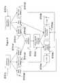
- FIG. 8is a flow chart of one embodiment of the present invention.
- FIG. 9is a flow chart of another embodiment of the present invention.
- Local spatial displacement vectorsare then computed for regions within the lung fields of the previous radiographic image, which is then “warped” to maximize the cross-correlation of the spatially shifted regions of the previous image and regions within the current image.
- the two images registered in this mannerare then combined such that the gray level of a pixel in the fixed current image is subtracted from the gray level of the corresponding pixel of the warped previous image.
- the resultis a “temporal subtraction” image in which dark pixels represent regions that appear more radiographically dense in the current image relative to the corresponding region in the previous image, bright pixels represent regions that appear less radiographically dense in the current image relative to the corresponding region in the previous image, and medium-gray pixels represent regions that exhibit no change between the images. Examples of the conventional approach are shown in FIGS. 1( a )- 1 ( c ).
- the “lung mask”provides an important component of the temporal subtraction process. Since subtraction images are intended to enhance the visualization of lung pathology, the temporal subtraction technique seeks to maximize the correlation among pixels within the lungs. Accordingly, a region that encompasses both lungs in the current image (the image to which the previous image will be registered and warped) is automatically identified during construction of the subtraction image. This region, known as the “lung mask,” will also encompass both lungs in the temporal subtraction image, since no coordinate transform is performed between the current image and the subtraction image ( FIG. 2 ). In the present invention, subsequent image analysis is performed within the region of the subtraction image spatially defined by the lung mask.
- the gray-level histogram constructed from pixels within the lung-mask region of a subtraction imageprovides important information about the content of the subtraction image.
- all pixels in the resulting subtraction imagewould contain the same gray level; a gray-level histogram represented by a delta function would result.
- the histogramwould be represented by a narrow Gaussian curve with a small full-width at half maximum (FWHM).
- FIGS. 3( a ) and 3 ( b )are lung mask images of a temporal subtraction image demonstrating pathologic change, and a temporal subtraction image without pathologic change, respectively.
- FIG. 3( c )is chart showing differences between the respective pathologic ( 302 ) and non-pathologic ( 301 ) gray-level histograms.
- the shape and position of the gray-level histogram obtained from the temporal subtraction imageare used to identify pathologic change between the two constituent images and to indicate a temporal subtraction image that reflects poor image registration.
- Histogram shapemay be quantified by attributes such as the full-width at half maximum (FWHM), skew, kurtosis, or the standard deviation of a Gaussian function fitted to the histogram.
- Histogram positionmay be quantified by attributes such as histogram mean, median, or mode.
- the CAD techniques that can be applied to the temporal subtraction imageare those described in U.S. Pat. Nos. 4,907,156, 5,452,367, 5,598,481, 5,638,458, 5,790,690 and 6,138,045, the entire contents of each which are incorporated herein by reference.
- the lung maskis convolved with a spatial smoothing filter to reduce noise.
- the gray-level histogramis then constructed from this pre-processed lung mask image.
- Statistics of this histograme.g., mode, mean, skew, and kurtosis
- a gray-level thresholdis established based on these histogram statistics. Since temporal subtraction images represent regions of progressive pathologic change as areas with lower gray levels (i.e., darker) than the average gray level of the image (although the opposite would hold for the progression of certain diseases such as emphysema), all lung mask pixels with gray levels less than this threshold remain “on,” while all other pixels are set to zero. Regions of contiguous “on” pixels are identified, and a region-growing technique is applied to spatially dilate the extent of each region.
- morphologic and gray-level featurese.g., area, circularity, mean gray level, and gray-level texture measures
- morphologic and gray-level featurese.g., area, circularity, mean gray level, and gray-level texture measures
- areas of pathologic change identified in this mannermay be presented as outlines (e.g., 401 in FIG. 4 ) in the subtraction image or as highlighted regions in the original radiographic image so that, in effect, temporal subtraction becomes a “background” process for computer-aided diagnosis.
- This techniqueis applicable not only to information derived from temporal subtraction images (including temporal subtraction images obtained from dual-energy studies), but, more broadly, the output of other CAD techniques may be represented in this manner.
- the methodinvolves superposition of the subtraction image, suitably processed by windowing and global filtering, as a transparent layer on the original image(s). This can result in a more “natural” appearance, while amplifying new abnormalities.
- An alternative approachrequires the identification (presumably through an automated or semi-automated CAD method) of an abnormal region.
- the CAD outputis then displayed within the original radiographic image through an enhancement of the pixels that spatially correspond to the identified abnormal region.
- Such enhancementinvolves application of a multiplicative factor, f(f>1.0), to the original gray-level values of these pixels.
- Alternative methods of enhancingmay also be used, including addition of a constant value to the original gray-level values of these pixels.
- the resultcan also be overlaid on a current original image ( FIG. 5 ) to provide a more natural radiographic appearance in which abnormalities maintain their internal contrast and relative structural gray-level information but appear, in general, more dense, thus reducing their subtlety.
- Modifications toward the periphery of the region ( 501 )may be made so that the enhanced region appears to blend with the background in a more continuous manner.
- the “false-positive” regionsare valuable for the assessment of registration accuracy. Histogram statistics may be used to identify varying degrees of misregistration due to the widening of the gray-level distribution, as previously described. The morphology and spatial distribution of false-positive regions also reflect registration accuracy, since regions of misregistration typically appear as alternating linear bands of dark and bright pixels (caused by rib misregistration, for example). Through a combination of pathologic change detection and registration accuracy assessment, the specific temporal subtraction images that may prove most clinically valuable are identified automatically.
- temporal subtraction imagemay be enhanced through an automated process that suppresses (through, for example, a median filtering process) the misregistered pixels.
- the approach described aboveconsiders the entire lung mask region.
- the lung mask regionmay be divided into multiple regions (for example, a quadrant-based approach that separately considers the upper and lower portions of the two lungs). The complete process is then applied independently within each region. This analysis allows for assessment of localized pathologic change and localized registration accuracy.
- the methodbegins with obtaining a temporal subtraction image (S 601 ).
- This temporal subtraction imageis than subjected to a lung mask to extract a lung mask region (S 602 ).
- the extracted lung mask regionis then subjected to spatial smoothing (S 603 ).
- the spatially smoothed datais then used to construct a gray level histogram (S 604 ).
- Histogram statisticsare then computed (S 605 ). These histogram statistics are used to determine registration accuracy (S 699 ) as well as to select gray level threshold information (S 605 ). From the gray level threshold information, a binary image is constructed (S 606 ).
- Geometric featuresinclude (but are not limited to) mean gray level, gray-level standard deviation, median gray level, and texture measures such as first moment of the power spectrum—all of these may be computed in the temporal subtraction image space as well as in the space of the two constituent original images.
- Morphologic featuresinclude (but are not limited to) eccentricity, compactness, circularity, area, fractal dimension, and orientation of principal axes.
- the values of these featuresare input to a rule-based scheme (or an automated classifier such as linear discriminant analysis or an artificial neural network) to distinguish between regions that represent pathologic change and those that represent misregistration.
- the extracted geometric and gray level featuresare then compared with the previously derived registration accuracy data so as to distinguish regions with pathological change from regions with misregistration artifacts (S 609 ).
- the regions with indications of pathologic changeare then super imposed as a CAD output onto the temporal subtraction image or on the original image (S 610 ).
- features to be extractedinclude area and circularity where regions smaller than a predefined minimum area or with circularity less than a predefined minimum were excluded as misregistration artifact. In other embodiments, other features may be extracted.
- the previously described temporal subtraction techniquemay be applied to images obtained from the energy subtraction process to further the clinical potential of both temporal and energy subtraction.
- temporal subtractionmay be applied to the standard radiographic images obtained from dual-energy imaging as described previously.
- the standard radiographic image from the current studyis held fixed as a template for image registration, while the standard radiographic image from the previous study is transformed through (1) rigid body rotation and translation based on a global alignment criterion, and (2) local spatial displacements that maximize the cross-correlation of the spatially shifted regions of the previous image and regions within the current image, and the two images registered in this manner are then combined such that the gray level of a pixel in the fixed current image is subtracted from the gray level of the corresponding pixel of the warped previous image.
- This processmay then be applied to the corresponding soft-tissue images (or to the corresponding bone images) for temporally sequential energy-subtraction studies.
- Application of the temporal subtraction technique directly to the soft-tissue (or bone images)generally may not produce temporal subtraction images with acceptable registration accuracy, since the soft-tissue image and the bone image each contain less anatomic information than the standard radiographic image. Both the rigid body transformations and the local spatial displacements of the temporal subtraction process make use of the anatomic information of two images to achieve proper image registration prior to subtraction.
- the temporal subtraction of soft-tissue or bone imagesmay be achieved based on the registration parameters obtained during the temporal subtraction of the standard radiographic image. Since the standard, soft-tissue, and bone images from a particular dual-energy study are intrinsically spatially aligned, registration parameters obtained for the temporal subtraction of the standard radiographic images from two temporally sequential dual-energy studies are applied directly (1) to the soft-tissue images obtained from the same pair of dual-energy studies to obtain a “soft-tissue temporal subtraction image” ( FIGS. 5( a )- 5 ( b )) and (2) to the bone images obtained from the same pair of dual-energy studies to obtain a “bone temporal subtraction image.”
- shift vectorscan also be obtained from the other images. Once the shift vectors are obtained based on the standard images obtained from temporally spaced dual-energy imaging studies, these shift vectors are applied to the soft-tissue images to produce a ‘warped’ soft-tissue image. Then the “warped” soft-tissue image will be subtracted from the other soft-tissue image to obtain a soft-tissue temporal subtraction image (again, “bone” may replace every occurrence of “soft-tissue” to describe the construction of a bone temporal subtraction image).
- the automated techniques for the identification of pathologic change in temporal subtraction imagesmay be applied.
- examples of these automated techniquesinclude those described in U.S. Pat. No. 5,987,345.
- the concepts described previouslyare used to identify pathologic change in the soft-tissue temporal subtraction and the bone temporal subtraction images.
- Dual energy imagesare obtained at separate times (S 701 A, S 701 B). Each dual energy acquisition results in a standard image (S 701 A 1 , S 701 B 1 ), a soft tissue image (S 701 A 3 , S 701 B 3 ), and a bone image (S 701 A 2 , S 701 B 2 ).
- the standard images obtained from the two dual energy acquisition stepsare then subjected to temporal subtraction (S 702 ), from which temporal subtraction parameters are obtained (S 703 ). These temporal subtraction parameters are then used in a corresponding soft tissue temporal subtraction (S 704 A) and/or a bone temporal subtraction (S 704 B) process.
- the soft tissue temporal subtraction(S 704 A) is exercised against the soft tissue images obtained from the two dual energy acquisitions (S 701 A 3 , S 701 B 3 ).
- the bone temporal subtraction process(S 704 B) is exercised against the bone images obtained from the two dual energy acquisitions (S 701 A 2 , S 701 B 2 ).
- the soft tissue temporal subtraction data and/or bone temporal subtraction dataare then subjected to corresponding computer-aided diagnosis (S 705 A, S 705 B) according to the method shown in FIG. 8 .
- the present inventionconveniently may be implemented using a conventional general purpose computer or micro-processor programmed according to the teachings of the present invention, as will be apparent to those skilled in the computer art.
- Appropriate softwaremay readily be prepared by programmers of ordinary skill based on the teachings of the present disclosure, as will be apparent to those skilled in the software art.
- a computer 900may implement the methods of the present invention, wherein the computer housing houses a motherboard which contains a CPU, memory (e.g., DRAM, ROM, EPROM, EEPROM, SRAM, SDRAM, and Flash RAM), and other optional special purpose logic devices (e.g., ASICS) or configurable logic devices (e.g., GAL and reprogrammable FPGA).
- the computeralso includes plural input devices, (e.g., keyboard and mouse), and a display card for controlling a monitor.
- the computermay include a floppy disk drive; other removable media devices (e.g.
- the computermay also include a compact disc reader, a compact disc reader/writer unit, or a compact disc jukebox, which may be connected to the same device bus or to another device bus.
- Examples of computer readable media associated with the present inventioninclude compact discs, hard disks, floppy disks, tape, magneto-optical disks, PROMs (e.g., EPROM, EEPROM, Flash EPROM), DRAM, SRAM, SDRAM, etc.
- PROMse.g., EPROM, EEPROM, Flash EPROM
- DRAMDRAM
- SRAMSRAM
- SDRAMSecure Digital Random Access Memory
- the present inventionincludes software for controlling both the hardware of the computer and for enabling the computer to interact with a human user.
- Such softwaremay include, but is not limited to, device drivers, operating systems and user applications, such as development tools.
- Computer program products of the present inventioninclude any computer readable medium which stores computer program instructions (e.g., computer code devices) which when executed by a computer causes the computer to perform the method of the present invention.
- the computer code devices of the present inventionmay be any interpretable or executable code mechanism, including but not limited to, scripts, interpreters, dynamic link libraries, Java classes, and complete executable programs. Moreover, parts of the processing of the present invention may be distributed (e.g., between (1) multiple CPUs or (2) at least one CPU and at least one configurable logic device) for better performance, reliability, and/or cost. For example, an outline or image may be selected on a first computer and sent to a second computer for remote diagnosis.
- the present inventionmay also be complemented with addition filtering techniques and tools to account for nodule contrast, degree of irregularity, texture features, etc.
- the inventionmay also be implemented by the preparation of application specific integrated circuits or by interconnecting an appropriate network of conventional component circuits, as will be readily apparent to those skilled in the art.
- the source of image data to the present inventionmay be any appropriate image acquisition device such as an X-ray machine, ultrasound machine, CT apparatus, and MRI apparatus. Further, the acquired data may be digitized if not already in digital form.
- the source of image data being obtained and processedmay be a memory storing data produced by an image acquisition device, and the memory may be local or remote, in which case a data communication network, such as PACS (Picture Archiving Computer System), may be used to access the image data for processing according to the present invention.
- PACSPicture Archiving Computer System
- the inventionmay be practiced otherwise than as specifically described herein.
- the previously described methods, devices, and computer program productsmay be adapted for use against organs other than lungs (e.g., liver, heart, brain, breast, etc.).
- the pathologic changes to be identifiedmay be cancerous or non-cancerous.
- the previously described methods, devices, and computer program productsmay be adapted for use with X-ray, CT, sonography, MRI, and other non-invasive examination technologies.
Landscapes
- Engineering & Computer Science (AREA)
- Health & Medical Sciences (AREA)
- Life Sciences & Earth Sciences (AREA)
- Physics & Mathematics (AREA)
- Medical Informatics (AREA)
- General Health & Medical Sciences (AREA)
- Radiology & Medical Imaging (AREA)
- General Physics & Mathematics (AREA)
- Theoretical Computer Science (AREA)
- Nuclear Medicine, Radiotherapy & Molecular Imaging (AREA)
- Optics & Photonics (AREA)
- Animal Behavior & Ethology (AREA)
- Biophysics (AREA)
- Biomedical Technology (AREA)
- Heart & Thoracic Surgery (AREA)
- Molecular Biology (AREA)
- Surgery (AREA)
- Pathology (AREA)
- High Energy & Nuclear Physics (AREA)
- Public Health (AREA)
- Veterinary Medicine (AREA)
- Computer Vision & Pattern Recognition (AREA)
- Human Computer Interaction (AREA)
- Quality & Reliability (AREA)
- Apparatus For Radiation Diagnosis (AREA)
Abstract
Description
- 1. Kinsey H, Vannelli B D, Fontana R S, et al.: Application of digital image change detection to diagnosis and follow-up of cancer involving the lungs.Proc SPIE70: 99-112, 1975.
- 2. Kano A, Doi K, MacMahon H, Hassell D D, Giger M L: Digital image subtraction of temporally subtracted chest images for detection of interval change.Med Phys21: 453-461, 1994.
- 3. Sasaki Y, Katsuragawa S, Ishikawa I, MacMahon H, Doi K: Usefulness of temporally subtracted images in the detection of lung nodules in digital chest radiographs.Radiology201:400, 1996.
- 4. Difazio M C, MacMahon H, Xu X W, Tsai P, Shiraishi J, Artnato S G Doi K: Digital chest radiography: Effect of temporal subtraction images on detection accuracy.Radiology202: 447-452, 1997.
- 5. Sasaki Y, Katsuragawa S, MacMahon H, Doi K: Application of temporally subtracted images with mobile computed radiography system in screening chest radiographs.Proc CARpp. 21-24, 1998
- 6. Katsuragawa S, Sasaki Y, MacMahon H, Ishida T, Doi K: Application of temporal subtraction to screening chest radiographs with a mobile computed radiography system.
Proc 1stInternational Workshop on Computed-Aided Diagnosis, pp. 51-56, 1998. - 7. Ishida T, Ashizawa K, Engelmann R, Katsuragawa S, MacMahon H, Doi K: Application of temporal subtraction for detection of interval changes in chest radiographs: Improvement of subtraction image using automated initial image matching.Journal of Digital Imaging12: 77-86, 1999.
- 8. Ishida T, Katsuragawa S, Nakamura K, MacMahon H, Doi K: Iterative image warping technique for temporal subtraction of sequential chest radiographs to detect interval change.Med Phys26: 1320-1329, 1999.
- 9. Katsuragawa S, Tagashira H, Li Q, MacMahon H, Doi K: Comparison of the quality of temporal subtraction images obtained with manual and automated methods of digital chest radiography.Journal of Digital Imaging12: 166-172, 1999.
- 10. Nakata H, Nakamura T, Uozumi H, Watanabe T, Aoki, et al.: Clinical usefulness of temporal subtraction on digital chest radiographs.CARS2000 pp. 793-797, 2000.
- 11. Uozumi T, Nakamura K, Watanabe H, Nakata H, Katsuragawa S, Doi K: ROC analysis of detection of metastatic pulmonary nodules on digital chest radiographs with temporal subtraction.Academic Radiology8: 871-878, 2001.
- 12. Tsubamoto M, Johkoh T, Kozuka T, Tomiyama N, Hamada S, Honda O, Mihara N, Koyama M, Maeda M, Nakamura H, Fujiwara K: Temporal subtraction for the detection of hazy pulmonary opacities on chest radiography.AJR179: 467-471, 2002.
- 13. Kakeda S, Nakamura K, Kamada K, Watanabe H, Nakata H, Katsuragawa S, Doi K: Improved detection of lung nodules by using a temporal subtraction technique.Radiology224: 145-151, 2002.
- 14. Johkoh T, Kozuka T, Tomiyama N, Hamada S, Honda O, Mihara N, Koyama M, Tsubamoto M, Maeda M, Nakamura H, Saki H, Fujiwara K: Temporal subtraction for detection of solitary pulmonary nodules on chest radiographs: evaluation of a commercially available computer-aided diagnosis system.Radiology223: 806-811, 2002.
- 15. Kido S, Kuriyama K, Kuroda C, Nakamura H, Ito W, Shimura K, Kato H: Detection of simulated pulmonary nodules by single-exposure dual-energy computed radiography of the chest: effect of a computer-aided diagnosis system (Part 2).European Journal of Radiology44(3):205-9, 2002.
- 16. Kido S, Nakamura H, Ito W, Shimura K, Kato H: Computerized detection of pulmonary nodules by single-exposure dual-energy computed radiography of the chest (part 1).European Journal of Radiology44(3):198-204, 2002.
- 17. Kido S, Kuriyama K, Hosomi N, Inoue E, Kuroda C, Horai T: Low-cost soft-copy display accuracy in the detection of pulmonary nodules by single-exposure dual-energy subtraction: comparison with hard-copy viewing.Journal of Digital Imaging13(1):33-7, 2000.
- 18. Kimme-Smith C, Davis D L, McNitt-Gray M, Goldin J, Hart E, Batra P, Johnson T D: Computed radiography dual energy subtraction: performance evaluation when detecting low-contrast lung nodules in an anthropomorphic phantom.Journal of Digital Imaging12(1):29-33, 1999.
- 19. Kamimura R, Takashima T: Clinical application of single dual-energy subtraction technique with digital storage-phosphor radiography.Journal of Digital Imaging8(1 Suppl 1):21-4, 1995.
- 20. Kido S, Ikezoe J, Naito H, Arisawa J, Tamura S, Kozuka T, Ito W, Shimura K, Kato H: Clinical evaluation of pulmonary nodules with single-exposure dual-energy subtraction chest radiography with an iterative noise-reduction algorithm.Radiology194(2):407-12, 1995.
- 21. Kido S, Ikezoe J, Naito H, Tamura S, Kozuka T, Ito W, Shimura K, Kato H: Single-exposure dual-energy chest images with computed radiography. Evaluation with simulated pulmonary nodules.Investigative Radiology28(6):482-7, 1993.
- 22. Ito W, Shimura K, Nakajima N, Ishida M, Kato H: Improvement of detection in computed radiography by new single-exposure dual-energy subtraction.Journal of Digital Imaging6(1):42-7, 1993.
- 23. Katoh T: Theoretical analysis of image formation process in quantitative dual-energy subtraction in a single exposure.Nippon Igaku Hoshasen Gakkai Zasshi—Nippon Acta Radiologica49(9):1152-67, 1989.
- 24. Ho J T, Kruger R A, Sorenson J A: Comparison of dual and single exposure techniques in dual-energy chest radiography.Medical Physics16(2):202-8, 1989.
- 25. Ishigaki T, Sakuma S, Ikeda M: One-shot dual-energy subtraction chest imaging with computed radiography: clinical evaluation of film images.Radiology168(1):67-72, 1988.
- 26. Takashima T: Single exposure energy subtraction chest radiography in the diagnosis of pulmonary cancer.Nippon Igaku Hoshasen Gakkai Zasshi—Nippon Acta Radiologica47(3):455-64, 1987.
- 27. Ishigaki T, Sakuma S, Horikawa Y, Ikeda M, Yamaguchi, H: One-shot dual-energy subtraction imaging.Radiology161(1):271-3, 1986.
- 28. Fraser R G, Barnes G T, Hickey N, Luna R, Katzenstein A, Alexander B, McElvein R, Zorn G, Sabbagh E, Robinson C A Jr.: Potential value of digital radiography. Preliminary observations on the use of dual-energy subtraction in the evaluation of pulmonary nodules.Chest89(4 Suppl):249S-252S, 1986.
Claims (23)
Priority Applications (2)
| Application Number | Priority Date | Filing Date | Title |
|---|---|---|---|
| US10/721,827US8265728B2 (en) | 2003-11-26 | 2003-11-26 | Automated method and system for the evaluation of disease and registration accuracy in the subtraction of temporally sequential medical images |
| PCT/US2004/032782WO2005057335A2 (en) | 2003-11-26 | 2004-11-04 | Subtraction of temporally sequential medical images |
Applications Claiming Priority (1)
| Application Number | Priority Date | Filing Date | Title |
|---|---|---|---|
| US10/721,827US8265728B2 (en) | 2003-11-26 | 2003-11-26 | Automated method and system for the evaluation of disease and registration accuracy in the subtraction of temporally sequential medical images |
Publications (2)
| Publication Number | Publication Date |
|---|---|
| US20050111718A1 US20050111718A1 (en) | 2005-05-26 |
| US8265728B2true US8265728B2 (en) | 2012-09-11 |
Family
ID=34591893
Family Applications (1)
| Application Number | Title | Priority Date | Filing Date |
|---|---|---|---|
| US10/721,827Expired - Fee RelatedUS8265728B2 (en) | 2003-11-26 | 2003-11-26 | Automated method and system for the evaluation of disease and registration accuracy in the subtraction of temporally sequential medical images |
Country Status (2)
| Country | Link |
|---|---|
| US (1) | US8265728B2 (en) |
| WO (1) | WO2005057335A2 (en) |
Cited By (10)
| Publication number | Priority date | Publication date | Assignee | Title |
|---|---|---|---|---|
| US20110235887A1 (en)* | 2010-03-25 | 2011-09-29 | Siemens Aktiengesellschaft | Computer-Aided Evaluation Of An Image Dataset |
| US9092691B1 (en) | 2014-07-18 | 2015-07-28 | Median Technologies | System for computing quantitative biomarkers of texture features in tomographic images |
| CN104997561A (en)* | 2014-04-17 | 2015-10-28 | 西门子公司 | Automatic identification of a potential pleural effusion |
| US20160180526A1 (en)* | 2014-12-22 | 2016-06-23 | Canon Kabushiki Kaisha | Image processing apparatus, image processing method, image processing system, and non-transitory computer-readable storage medium |
| US9642572B2 (en) | 2009-02-02 | 2017-05-09 | Joint Vue, LLC | Motion Tracking system with inertial-based sensing units |
| US20190038918A1 (en)* | 2017-08-01 | 2019-02-07 | Varex Imaging Corporation | Dual-layer detector for soft tissue motion tracking |
| US10512451B2 (en) | 2010-08-02 | 2019-12-24 | Jointvue, Llc | Method and apparatus for three dimensional reconstruction of a joint using ultrasound |
| US10517568B2 (en) | 2011-08-12 | 2019-12-31 | Jointvue, Llc | 3-D ultrasound imaging device and methods |
| US11123040B2 (en) | 2011-10-14 | 2021-09-21 | Jointvue, Llc | Real-time 3-D ultrasound reconstruction of knee and its implications for patient specific implants and 3-D joint injections |
| US11284849B2 (en)* | 2015-04-13 | 2022-03-29 | Case Western Reserve University | Dual energy x-ray coronary calcium grading |
Families Citing this family (56)
| Publication number | Priority date | Publication date | Assignee | Title |
|---|---|---|---|---|
| US8064660B2 (en)* | 2004-02-27 | 2011-11-22 | National University Of Singapore | Method and system for detection of bone fractures |
| JP2007105352A (en)* | 2005-10-17 | 2007-04-26 | Fujifilm Corp | Differential image display device, differential image display method and program thereof |
| US7769216B2 (en) | 2005-12-29 | 2010-08-03 | Hologic, Inc. | Facilitating comparison of medical images |
| US7620227B2 (en)* | 2005-12-29 | 2009-11-17 | General Electric Co. | Computer-aided detection system utilizing temporal analysis as a precursor to spatial analysis |
| WO2007095330A2 (en) | 2006-02-15 | 2007-08-23 | Hologic Inc | Breast biopsy and needle localization using tomosynthesis systems |
| US7680303B2 (en)* | 2006-09-11 | 2010-03-16 | Mitsubishi Electric Research Laboratories, Inc. | Image registration using joint spatial gradient maximization |
| DE602007002693D1 (en)* | 2007-02-09 | 2009-11-19 | Agfa Gevaert | Visual highlighting of interval changes using a time subtraction technique |
| EP1956552B1 (en)* | 2007-02-09 | 2011-06-08 | Agfa-Gevaert | Visual enhancement of interval changes using a temporal subtraction technique |
| EP1956553B1 (en)* | 2007-02-09 | 2009-08-19 | Agfa-Gevaert | Visual enhancement of interval changes using a temporal subtraction technique. |
| EP2225679A1 (en)* | 2007-12-18 | 2010-09-08 | Koninklijke Philips Electronics N.V. | Consistency metric based image registration |
| WO2010085898A1 (en)* | 2009-02-02 | 2010-08-05 | Calgary Scientific Inc. | Image data transmission from gpu to system memory |
| US10699469B2 (en) | 2009-02-03 | 2020-06-30 | Calgary Scientific Inc. | Configurable depth-of-field raycaster for medical imaging |
| US9082191B2 (en)* | 2009-09-25 | 2015-07-14 | Calgary Scientific Inc. | Level set segmentation of volume data |
| ES2862525T3 (en) | 2009-10-08 | 2021-10-07 | Hologic Inc | Needle Breast Biopsy System and Method of Use |
| JP5564385B2 (en)* | 2010-09-29 | 2014-07-30 | 富士フイルム株式会社 | Radiographic imaging apparatus, radiographic imaging method and program |
| CA2854992C (en)* | 2010-11-24 | 2021-05-04 | Blackford Analysis Limited | Process and apparatus for data registration |
| US20120133600A1 (en) | 2010-11-26 | 2012-05-31 | Hologic, Inc. | User interface for medical image review workstation |
| DE102011004120B4 (en)* | 2011-02-15 | 2017-04-06 | Siemens Healthcare Gmbh | Method, image data record processing device, X-ray system and computer program for the correction of image data of an examination object |
| JP6057922B2 (en) | 2011-03-08 | 2017-01-11 | ホロジック, インコーポレイテッドHologic, Inc. | System and method for dual energy and / or contrast enhanced breast imaging for screening, diagnosis and biopsy |
| WO2013001344A2 (en) | 2011-06-29 | 2013-01-03 | Calgary Scientific Inc. | Method for cataloguing and accessing digital cinema frame content |
| EP2782505B1 (en) | 2011-11-27 | 2020-04-22 | Hologic, Inc. | System and method for generating a 2d image using mammography and/or tomosynthesis image data |
| JP6240097B2 (en) | 2012-02-13 | 2017-11-29 | ホロジック インコーポレイティッド | How to navigate a tomosynthesis stack using composite image data |
| US20130342577A1 (en)* | 2012-06-20 | 2013-12-26 | Carestream Health, Inc. | Image synthesis for diagnostic review |
| CN105451657A (en) | 2013-03-15 | 2016-03-30 | 霍罗吉克公司 | System and method for navigating tomosynthesis stack including automatic focusing |
| US10092358B2 (en) | 2013-03-15 | 2018-10-09 | Hologic, Inc. | Tomosynthesis-guided biopsy apparatus and method |
| EP3060132B1 (en)* | 2013-10-24 | 2019-12-04 | Hologic, Inc. | System and method for navigating x-ray guided breast biopsy |
| JP6506769B2 (en) | 2014-02-28 | 2019-04-24 | ホロジック, インコーポレイテッドHologic, Inc. | System and method for generating and displaying tomosynthesis image slabs |
| GB2536274B (en)* | 2015-03-12 | 2019-10-16 | Mirada Medical Ltd | Method and apparatus for assessing image registration |
| CN106611411B (en)* | 2015-10-19 | 2020-06-26 | 上海联影医疗科技有限公司 | Method for segmenting ribs in medical image and medical image processing device |
| US9710911B2 (en)* | 2015-11-30 | 2017-07-18 | Raytheon Company | System and method for generating a background reference image from a series of images to facilitate moving object identification |
| US9536054B1 (en) | 2016-01-07 | 2017-01-03 | ClearView Diagnostics Inc. | Method and means of CAD system personalization to provide a confidence level indicator for CAD system recommendations |
| US10339650B2 (en) | 2016-01-07 | 2019-07-02 | Koios Medical, Inc. | Method and means of CAD system personalization to reduce intraoperator and interoperator variation |
| AT16426U1 (en)* | 2016-03-02 | 2019-08-15 | Mathias Zirm Dr | Remote diagnostic support method |
| US10346982B2 (en) | 2016-08-22 | 2019-07-09 | Koios Medical, Inc. | Method and system of computer-aided detection using multiple images from different views of a region of interest to improve detection accuracy |
| EP3533027B1 (en)* | 2016-10-28 | 2021-04-14 | Koninklijke Philips N.V. | Automatic ct detection and visualization of active bleeding and blood extravasation |
| CN110621233B (en) | 2017-03-30 | 2023-12-12 | 豪洛捷公司 | Method for processing breast tissue image data |
| EP3600047A1 (en) | 2017-03-30 | 2020-02-05 | Hologic, Inc. | System and method for hierarchical multi-level feature image synthesis and representation |
| EP3600052A1 (en) | 2017-03-30 | 2020-02-05 | Hologic, Inc. | System and method for targeted object enhancement to generate synthetic breast tissue images |
| US10242446B2 (en)* | 2017-05-10 | 2019-03-26 | Konica Minolta, Inc. | Image processing apparatus and computer-readable recording medium |
| CN107194918B (en)* | 2017-05-16 | 2020-11-17 | 北京大学 | Data analysis method and device |
| WO2018236565A1 (en) | 2017-06-20 | 2018-12-27 | Hologic, Inc. | METHOD AND SYSTEM FOR MEDICAL IMAGING WITH DYNAMIC SELF-LEARNING |
| US11382601B2 (en)* | 2018-03-01 | 2022-07-12 | Fujifilm Sonosite, Inc. | Method and apparatus for annotating ultrasound examinations |
| EP3787520B1 (en) | 2018-05-04 | 2024-09-25 | Hologic, Inc. | Biopsy needle visualization |
| US12121304B2 (en) | 2018-05-04 | 2024-10-22 | Hologic, Inc. | Introducer and localization wire visualization |
| WO2020068851A1 (en) | 2018-09-24 | 2020-04-02 | Hologic, Inc. | Breast mapping and abnormality localization |
| US10957038B2 (en) | 2019-02-04 | 2021-03-23 | International Business Machines Corporation | Machine learning to determine clinical change from prior images |
| US11883206B2 (en) | 2019-07-29 | 2024-01-30 | Hologic, Inc. | Personalized breast imaging system |
| EP4439580A3 (en) | 2019-09-27 | 2024-12-25 | Hologic, Inc. | Ai system for predicting reading time and reading complexity for reviewing 2d/3d breast images |
| US11481038B2 (en) | 2020-03-27 | 2022-10-25 | Hologic, Inc. | Gesture recognition in controlling medical hardware or software |
| CN112288639A (en)* | 2020-07-20 | 2021-01-29 | 深圳市智影医疗科技有限公司 | Image contrast subtraction method, device, terminal device and storage medium |
| JP7679193B2 (en)* | 2020-11-20 | 2025-05-19 | キヤノン株式会社 | CONTROL DEVICE, RADIATION IMAGING SYSTEM, CONTROL METHOD, AND PROGRAM |
| CN113181639B (en)* | 2021-04-28 | 2024-06-04 | 网易(杭州)网络有限公司 | Graphic processing method and device in game |
| US12254586B2 (en) | 2021-10-25 | 2025-03-18 | Hologic, Inc. | Auto-focus tool for multimodality image review |
| JP7737288B2 (en)* | 2021-11-02 | 2025-09-10 | 富士フイルム株式会社 | Radiation image processing device, method and program |
| WO2023097279A1 (en) | 2021-11-29 | 2023-06-01 | Hologic, Inc. | Systems and methods for correlating objects of interest |
| CN118644536B (en)* | 2024-08-19 | 2024-10-15 | 长春中医药大学 | Soft tissue injury image data processing method for orthopedics |
Citations (23)
| Publication number | Priority date | Publication date | Assignee | Title |
|---|---|---|---|---|
| US4482918A (en) | 1982-04-26 | 1984-11-13 | General Electric Company | Method and apparatus for X-ray image subtraction |
| US4907156A (en)* | 1987-06-30 | 1990-03-06 | University Of Chicago | Method and system for enhancement and detection of abnormal anatomic regions in a digital image |
| US5570430A (en)* | 1994-05-31 | 1996-10-29 | University Of Washington | Method for determining the contour of an in vivo organ using multiple image frames of the organ |
| US5931780A (en)* | 1993-11-29 | 1999-08-03 | Arch Development Corporation | Method and system for the computerized radiographic analysis of bone |
| US5987345A (en) | 1996-11-29 | 1999-11-16 | Arch Development Corporation | Method and system for displaying medical images |
| WO2000025255A1 (en) | 1998-10-26 | 2000-05-04 | R2 Technology, Inc. | Method and system for computer-aided lesion detection using information from multiple images |
| US6240201B1 (en) | 1998-07-24 | 2001-05-29 | Arch Development Corporation | Computerized detection of lung nodules using energy-subtracted soft-tissue and standard chest images |
| US6282307B1 (en)* | 1998-02-23 | 2001-08-28 | Arch Development Corporation | Method and system for the automated delineation of lung regions and costophrenic angles in chest radiographs |
| US20020090126A1 (en)* | 2000-11-20 | 2002-07-11 | Fuji Photo Film Co., Ltd. | Method and apparatus for detecting anomalous shadows |
| US20020102014A1 (en) | 2001-01-31 | 2002-08-01 | Osamu Ozaki | Method and system for automatically producing a temporally processed image |
| US20030147497A1 (en)* | 2002-01-28 | 2003-08-07 | Avinash Gopal B. | Robust and efficient decomposition algorithm for digital x-ray de imaging |
| US20030152258A1 (en)* | 2002-01-28 | 2003-08-14 | Jabri Kadri N. | Automatic selection of the log-subtraction decomposition parameters for dual energy chest radiography |
| US20030215119A1 (en)* | 2002-05-15 | 2003-11-20 | Renuka Uppaluri | Computer aided diagnosis from multiple energy images |
| US6661873B2 (en)* | 2002-01-28 | 2003-12-09 | Ge Medical Systems Global Technology Company, Llc | Motion artifacts reduction algorithm for two-exposure dual-energy radiography |
| US6690761B2 (en)* | 2000-10-11 | 2004-02-10 | Imaging Therapeutics, Inc. | Methods and devices for analysis of X-ray images |
| US20040105527A1 (en)* | 2002-11-22 | 2004-06-03 | Matthieu Ferrant | Methods and apparatus for the classification of nodules |
| US6771736B2 (en) | 2002-07-25 | 2004-08-03 | Ge Medical Systems Global Technology Company, Llc | Method for displaying temporal changes in spatially matched images |
| US6782137B1 (en) | 1999-11-24 | 2004-08-24 | General Electric Company | Digital image display improvement system and method |
| US20040225218A1 (en)* | 2003-05-06 | 2004-11-11 | Siemens Medical Solutions Usa, Inc. | Identifying clinical markers in spatial compounding ultrasound imaging |
| US20040252873A1 (en)* | 2003-06-13 | 2004-12-16 | Ge Medical Systems Global Technology Company, Llc | Analysis of temporal change using dual or multi-energy decomposition images |
| US6956373B1 (en)* | 2002-01-02 | 2005-10-18 | Hugh Keith Brown | Opposed orthogonal fusion system and method for generating color segmented MRI voxel matrices |
| US7282723B2 (en)* | 2002-07-09 | 2007-10-16 | Medispectra, Inc. | Methods and apparatus for processing spectral data for use in tissue characterization |
| US7403646B2 (en)* | 2002-10-24 | 2008-07-22 | Canon Kabushiki Kaisha | Image processing apparatus, image processing method, program, and recording medium for generating a difference image from a first radiographic image and second radiographic image |
- 2003
- 2003-11-26USUS10/721,827patent/US8265728B2/ennot_activeExpired - Fee Related
- 2004
- 2004-11-04WOPCT/US2004/032782patent/WO2005057335A2/enactiveApplication Filing
Patent Citations (27)
| Publication number | Priority date | Publication date | Assignee | Title |
|---|---|---|---|---|
| US4482918A (en) | 1982-04-26 | 1984-11-13 | General Electric Company | Method and apparatus for X-ray image subtraction |
| US4907156A (en)* | 1987-06-30 | 1990-03-06 | University Of Chicago | Method and system for enhancement and detection of abnormal anatomic regions in a digital image |
| US5931780A (en)* | 1993-11-29 | 1999-08-03 | Arch Development Corporation | Method and system for the computerized radiographic analysis of bone |
| US6205348B1 (en)* | 1993-11-29 | 2001-03-20 | Arch Development Corporation | Method and system for the computerized radiographic analysis of bone |
| US5570430A (en)* | 1994-05-31 | 1996-10-29 | University Of Washington | Method for determining the contour of an in vivo organ using multiple image frames of the organ |
| US5987345A (en) | 1996-11-29 | 1999-11-16 | Arch Development Corporation | Method and system for displaying medical images |
| US6282307B1 (en)* | 1998-02-23 | 2001-08-28 | Arch Development Corporation | Method and system for the automated delineation of lung regions and costophrenic angles in chest radiographs |
| US6240201B1 (en) | 1998-07-24 | 2001-05-29 | Arch Development Corporation | Computerized detection of lung nodules using energy-subtracted soft-tissue and standard chest images |
| WO2000025255A1 (en) | 1998-10-26 | 2000-05-04 | R2 Technology, Inc. | Method and system for computer-aided lesion detection using information from multiple images |
| US6782137B1 (en) | 1999-11-24 | 2004-08-24 | General Electric Company | Digital image display improvement system and method |
| US6690761B2 (en)* | 2000-10-11 | 2004-02-10 | Imaging Therapeutics, Inc. | Methods and devices for analysis of X-ray images |
| US7120225B2 (en)* | 2000-10-11 | 2006-10-10 | Imaging Therapeutics, Inc. | Methods and devices for analysis of x-ray images |
| US6811310B2 (en)* | 2000-10-11 | 2004-11-02 | Imaging Therapeutics, Inc. | Methods and devices for analysis of X-ray images |
| US20020090126A1 (en)* | 2000-11-20 | 2002-07-11 | Fuji Photo Film Co., Ltd. | Method and apparatus for detecting anomalous shadows |
| US20020102014A1 (en) | 2001-01-31 | 2002-08-01 | Osamu Ozaki | Method and system for automatically producing a temporally processed image |
| US6956373B1 (en)* | 2002-01-02 | 2005-10-18 | Hugh Keith Brown | Opposed orthogonal fusion system and method for generating color segmented MRI voxel matrices |
| US6661873B2 (en)* | 2002-01-28 | 2003-12-09 | Ge Medical Systems Global Technology Company, Llc | Motion artifacts reduction algorithm for two-exposure dual-energy radiography |
| US20030152258A1 (en)* | 2002-01-28 | 2003-08-14 | Jabri Kadri N. | Automatic selection of the log-subtraction decomposition parameters for dual energy chest radiography |
| US20030147497A1 (en)* | 2002-01-28 | 2003-08-07 | Avinash Gopal B. | Robust and efficient decomposition algorithm for digital x-ray de imaging |
| US20030215119A1 (en)* | 2002-05-15 | 2003-11-20 | Renuka Uppaluri | Computer aided diagnosis from multiple energy images |
| US7263214B2 (en)* | 2002-05-15 | 2007-08-28 | Ge Medical Systems Global Technology Company Llc | Computer aided diagnosis from multiple energy images |
| US7282723B2 (en)* | 2002-07-09 | 2007-10-16 | Medispectra, Inc. | Methods and apparatus for processing spectral data for use in tissue characterization |
| US6771736B2 (en) | 2002-07-25 | 2004-08-03 | Ge Medical Systems Global Technology Company, Llc | Method for displaying temporal changes in spatially matched images |
| US7403646B2 (en)* | 2002-10-24 | 2008-07-22 | Canon Kabushiki Kaisha | Image processing apparatus, image processing method, program, and recording medium for generating a difference image from a first radiographic image and second radiographic image |
| US20040105527A1 (en)* | 2002-11-22 | 2004-06-03 | Matthieu Ferrant | Methods and apparatus for the classification of nodules |
| US20040225218A1 (en)* | 2003-05-06 | 2004-11-11 | Siemens Medical Solutions Usa, Inc. | Identifying clinical markers in spatial compounding ultrasound imaging |
| US20040252873A1 (en)* | 2003-06-13 | 2004-12-16 | Ge Medical Systems Global Technology Company, Llc | Analysis of temporal change using dual or multi-energy decomposition images |
Non-Patent Citations (4)
| Title |
|---|
| Michael S. Van Lysel, M.S. et al., Work in Progress: Hybrid Temporal-Energy Subtraction in Digital Fluoroscopy; Radiology 147: 869-874, Jun. 1983. |
| Shigeru Sanada, et al.; Temporal Subtraction Technique for detection of Subtle Anomalies on Temporally Sequential Bone-subtracted Chest Radiographs by Energy Subtraction.; Jpn. J. Radiol. Technol. vol. 56 No. 3.: Mar. 2000. |
| Shoji Kido, et al., Detection of simulated pulmonary nodules by single-exposure dual-energy computed radiography of the chest: effect of a computer-aided diagnosis system (Part 2); PII: S0720-048 (02) 00269-3; European Journal of Radiology (EJR) 44 (2002) 205-209. |
| Shoji Kido, et al.; Computerized detection of pulmonary nodules by single-exposure dual-energy computed radiography of the chest (part 1); PII: S0720-048X (02) 00268-1, European Journal of Radiology (EJR) 44 (2002) 198-204. |
Cited By (18)
| Publication number | Priority date | Publication date | Assignee | Title |
|---|---|---|---|---|
| US9642572B2 (en) | 2009-02-02 | 2017-05-09 | Joint Vue, LLC | Motion Tracking system with inertial-based sensing units |
| US11342071B2 (en) | 2009-02-02 | 2022-05-24 | Jointvue, Llc | Noninvasive diagnostic system |
| US11004561B2 (en) | 2009-02-02 | 2021-05-11 | Jointvue Llc | Motion tracking system with inertial-based sensing units |
| US9545238B2 (en)* | 2010-03-25 | 2017-01-17 | Siemens Aktiengesellschaft | Computer-aided evaluation of an image dataset |
| US20110235887A1 (en)* | 2010-03-25 | 2011-09-29 | Siemens Aktiengesellschaft | Computer-Aided Evaluation Of An Image Dataset |
| US10512451B2 (en) | 2010-08-02 | 2019-12-24 | Jointvue, Llc | Method and apparatus for three dimensional reconstruction of a joint using ultrasound |
| US10517568B2 (en) | 2011-08-12 | 2019-12-31 | Jointvue, Llc | 3-D ultrasound imaging device and methods |
| US11529119B2 (en) | 2011-10-14 | 2022-12-20 | Jointvue, Llc | Real-time 3-D ultrasound reconstruction of knee and its implications for patient specific implants and 3-D joint injections |
| US11123040B2 (en) | 2011-10-14 | 2021-09-21 | Jointvue, Llc | Real-time 3-D ultrasound reconstruction of knee and its implications for patient specific implants and 3-D joint injections |
| CN104997561B (en)* | 2014-04-17 | 2018-02-02 | 西门子公司 | The automatic identification of potential pleura sepage |
| US10548555B2 (en) | 2014-04-17 | 2020-02-04 | Siemens Aktiengesellschaft | Automatic identification of a potential pleural effusion |
| CN104997561A (en)* | 2014-04-17 | 2015-10-28 | 西门子公司 | Automatic identification of a potential pleural effusion |
| US9092691B1 (en) | 2014-07-18 | 2015-07-28 | Median Technologies | System for computing quantitative biomarkers of texture features in tomographic images |
| US20160180526A1 (en)* | 2014-12-22 | 2016-06-23 | Canon Kabushiki Kaisha | Image processing apparatus, image processing method, image processing system, and non-transitory computer-readable storage medium |
| US10692198B2 (en)* | 2014-12-22 | 2020-06-23 | Canon Kabushiki Kaisha | Image processing apparatus, image processing method, image processing system, and non-transitory computer-readable storage medium for presenting three-dimensional images |
| US11284849B2 (en)* | 2015-04-13 | 2022-03-29 | Case Western Reserve University | Dual energy x-ray coronary calcium grading |
| US20190038918A1 (en)* | 2017-08-01 | 2019-02-07 | Varex Imaging Corporation | Dual-layer detector for soft tissue motion tracking |
| US11000701B2 (en)* | 2017-08-01 | 2021-05-11 | Varex Imaging Corporation | Dual-layer detector for soft tissue motion tracking |
Also Published As
| Publication number | Publication date |
|---|---|
| WO2005057335A3 (en) | 2006-07-13 |
| US20050111718A1 (en) | 2005-05-26 |
| WO2005057335A2 (en) | 2005-06-23 |
Similar Documents
| Publication | Publication Date | Title |
|---|---|---|
| US8265728B2 (en) | Automated method and system for the evaluation of disease and registration accuracy in the subtraction of temporally sequential medical images | |
| US11284849B2 (en) | Dual energy x-ray coronary calcium grading | |
| Giger et al. | Image processing and computer-aided diagnosis | |
| Giger et al. | Anniversary paper: history and status of CAD and quantitative image analysis: the role of medical physics and AAPM | |
| Li et al. | High-resolution chest x-ray bone suppression using unpaired CT structural priors | |
| Banik et al. | Detection of architectural distortion in prior mammograms | |
| Reeves et al. | Computer-aided diagnosis for lung cancer | |
| US20080025592A1 (en) | System and Method for Detection of Breast Masses and Calcifications Using the Tomosynthesis Projection and Reconstructed Images | |
| US20070052700A1 (en) | System and method for 3D CAD using projection images | |
| EP1947606A1 (en) | Medical image processing apparatus and medical image processing method | |
| JP2002369079A (en) | Method for improving illness diagnosis by using contrast emphasis presentation | |
| JP2002521896A (en) | Computerized lung nodule detection by energy difference method using soft tissue chest image and standard chest image | |
| US20050084178A1 (en) | Radiological image processing based on different views of temporal images | |
| JP2008080121A (en) | Method and system for identifying regions in an image | |
| Hogeweg et al. | Suppression of translucent elongated structures: applications in chest radiography | |
| US11058383B2 (en) | Apparatus for the detection of opacities in X-ray images | |
| Sogancioglu et al. | Nodule detection and generation on chest x-rays: Node21 challenge | |
| Chang et al. | Pulmonary micronodule detection from 3D chest CT | |
| Wen et al. | Enhanced coronary calcium visualization and detection from dual energy chest x-rays with sliding organ registration | |
| US20050002548A1 (en) | Automatic detection of growing nodules | |
| Chi et al. | Stenosis detection and quantification on cardiac CTCA using panoramic MIP of coronary arteries | |
| Van Velzen et al. | Generative models for reproducible coronary calcium scoring | |
| JP5048233B2 (en) | Method and system for anatomical shape detection in a CAD system | |
| Armato III et al. | Temporal subtraction of dual‐energy chest radiographs | |
| Delogu et al. | Preprocessing methods for nodule detection in lung CT |
Legal Events
| Date | Code | Title | Description |
|---|---|---|---|
| AS | Assignment | Owner name:CHICAGO, UNIVERSITY OF, ILLINOIS Free format text:ASSIGNMENT OF ASSIGNORS INTEREST;ASSIGNORS:MACMAHON, HEBER;ARMATO, SAMUEL G., III;REEL/FRAME:015263/0987 Effective date:20040114 | |
| AS | Assignment | Owner name:NATIONAL INSTITUTES OF HEALTH (NIH), U.S. DEPT. OF Free format text:EXECUTIVE ORDER 9424, CONFIRMATORY LICENSE;ASSIGNOR:UNIVERSITY OF CHICAGO;REEL/FRAME:021320/0086 Effective date:20051206 | |
| AS | Assignment | Owner name:NATIONAL INSTITUTES OF HEALTH (NIH), U.S. DEPT. OF Free format text:CONFIRMATORY LICENSE;ASSIGNOR:UNIVERSITY OF CHICAGO;REEL/FRAME:024792/0530 Effective date:20051206 | |
| STCF | Information on status: patent grant | Free format text:PATENTED CASE | |
| FPAY | Fee payment | Year of fee payment:4 | |
| FEPP | Fee payment procedure | Free format text:MAINTENANCE FEE REMINDER MAILED (ORIGINAL EVENT CODE: REM.); ENTITY STATUS OF PATENT OWNER: SMALL ENTITY | |
| LAPS | Lapse for failure to pay maintenance fees | Free format text:PATENT EXPIRED FOR FAILURE TO PAY MAINTENANCE FEES (ORIGINAL EVENT CODE: EXP.); ENTITY STATUS OF PATENT OWNER: SMALL ENTITY | |
| STCH | Information on status: patent discontinuation | Free format text:PATENT EXPIRED DUE TO NONPAYMENT OF MAINTENANCE FEES UNDER 37 CFR 1.362 | |
| FP | Lapsed due to failure to pay maintenance fee | Effective date:20200911 |