US8265545B2 - Wireless environment method and apparatus - Google Patents
Wireless environment method and apparatusDownload PDFInfo
- Publication number
- US8265545B2 US8265545B2US13/101,841US201113101841AUS8265545B2US 8265545 B2US8265545 B2US 8265545B2US 201113101841 AUS201113101841 AUS 201113101841AUS 8265545 B2US8265545 B2US 8265545B2
- Authority
- US
- United States
- Prior art keywords
- digital audio
- user interface
- digital
- program information
- program
- Prior art date
- Legal status (The legal status is an assumption and is not a legal conclusion. Google has not performed a legal analysis and makes no representation as to the accuracy of the status listed.)
- Expired - Fee Related
Links
Images


Classifications
- G—PHYSICS
- G06—COMPUTING OR CALCULATING; COUNTING
- G06F—ELECTRIC DIGITAL DATA PROCESSING
- G06F3/00—Input arrangements for transferring data to be processed into a form capable of being handled by the computer; Output arrangements for transferring data from processing unit to output unit, e.g. interface arrangements
- G06F3/16—Sound input; Sound output
- G06F3/165—Management of the audio stream, e.g. setting of volume, audio stream path
- H—ELECTRICITY
- H04—ELECTRIC COMMUNICATION TECHNIQUE
- H04N—PICTORIAL COMMUNICATION, e.g. TELEVISION
- H04N7/00—Television systems
- H04N7/10—Adaptations for transmission by electrical cable
- G—PHYSICS
- G05—CONTROLLING; REGULATING
- G05B—CONTROL OR REGULATING SYSTEMS IN GENERAL; FUNCTIONAL ELEMENTS OF SUCH SYSTEMS; MONITORING OR TESTING ARRANGEMENTS FOR SUCH SYSTEMS OR ELEMENTS
- G05B15/00—Systems controlled by a computer
- G05B15/02—Systems controlled by a computer electric
- G—PHYSICS
- G06—COMPUTING OR CALCULATING; COUNTING
- G06F—ELECTRIC DIGITAL DATA PROCESSING
- G06F16/00—Information retrieval; Database structures therefor; File system structures therefor
- G06F16/60—Information retrieval; Database structures therefor; File system structures therefor of audio data
- G06F16/63—Querying
- G—PHYSICS
- G06—COMPUTING OR CALCULATING; COUNTING
- G06F—ELECTRIC DIGITAL DATA PROCESSING
- G06F16/00—Information retrieval; Database structures therefor; File system structures therefor
- G06F16/60—Information retrieval; Database structures therefor; File system structures therefor of audio data
- G06F16/68—Retrieval characterised by using metadata, e.g. metadata not derived from the content or metadata generated manually
- G—PHYSICS
- G06—COMPUTING OR CALCULATING; COUNTING
- G06F—ELECTRIC DIGITAL DATA PROCESSING
- G06F3/00—Input arrangements for transferring data to be processed into a form capable of being handled by the computer; Output arrangements for transferring data from processing unit to output unit, e.g. interface arrangements
- G06F3/01—Input arrangements or combined input and output arrangements for interaction between user and computer
- G06F3/03—Arrangements for converting the position or the displacement of a member into a coded form
- G06F3/033—Pointing devices displaced or positioned by the user, e.g. mice, trackballs, pens or joysticks; Accessories therefor
- G06F3/0354—Pointing devices displaced or positioned by the user, e.g. mice, trackballs, pens or joysticks; Accessories therefor with detection of 2D relative movements between the device, or an operating part thereof, and a plane or surface, e.g. 2D mice, trackballs, pens or pucks
- G06F3/03547—Touch pads, in which fingers can move on a surface
- G—PHYSICS
- G06—COMPUTING OR CALCULATING; COUNTING
- G06F—ELECTRIC DIGITAL DATA PROCESSING
- G06F3/00—Input arrangements for transferring data to be processed into a form capable of being handled by the computer; Output arrangements for transferring data from processing unit to output unit, e.g. interface arrangements
- G06F3/01—Input arrangements or combined input and output arrangements for interaction between user and computer
- G06F3/03—Arrangements for converting the position or the displacement of a member into a coded form
- G06F3/041—Digitisers, e.g. for touch screens or touch pads, characterised by the transducing means
- G—PHYSICS
- G06—COMPUTING OR CALCULATING; COUNTING
- G06F—ELECTRIC DIGITAL DATA PROCESSING
- G06F3/00—Input arrangements for transferring data to be processed into a form capable of being handled by the computer; Output arrangements for transferring data from processing unit to output unit, e.g. interface arrangements
- G06F3/01—Input arrangements or combined input and output arrangements for interaction between user and computer
- G06F3/048—Interaction techniques based on graphical user interfaces [GUI]
- G06F3/0484—Interaction techniques based on graphical user interfaces [GUI] for the control of specific functions or operations, e.g. selecting or manipulating an object, an image or a displayed text element, setting a parameter value or selecting a range
- G06F3/04842—Selection of displayed objects or displayed text elements
- G—PHYSICS
- G06—COMPUTING OR CALCULATING; COUNTING
- G06F—ELECTRIC DIGITAL DATA PROCESSING
- G06F3/00—Input arrangements for transferring data to be processed into a form capable of being handled by the computer; Output arrangements for transferring data from processing unit to output unit, e.g. interface arrangements
- G06F3/01—Input arrangements or combined input and output arrangements for interaction between user and computer
- G06F3/048—Interaction techniques based on graphical user interfaces [GUI]
- G06F3/0484—Interaction techniques based on graphical user interfaces [GUI] for the control of specific functions or operations, e.g. selecting or manipulating an object, an image or a displayed text element, setting a parameter value or selecting a range
- G06F3/04847—Interaction techniques to control parameter settings, e.g. interaction with sliders or dials
- G—PHYSICS
- G06—COMPUTING OR CALCULATING; COUNTING
- G06Q—INFORMATION AND COMMUNICATION TECHNOLOGY [ICT] SPECIALLY ADAPTED FOR ADMINISTRATIVE, COMMERCIAL, FINANCIAL, MANAGERIAL OR SUPERVISORY PURPOSES; SYSTEMS OR METHODS SPECIALLY ADAPTED FOR ADMINISTRATIVE, COMMERCIAL, FINANCIAL, MANAGERIAL OR SUPERVISORY PURPOSES, NOT OTHERWISE PROVIDED FOR
- G06Q20/00—Payment architectures, schemes or protocols
- G06Q20/08—Payment architectures
- G06Q20/12—Payment architectures specially adapted for electronic shopping systems
- G06Q20/123—Shopping for digital content
- G—PHYSICS
- G06—COMPUTING OR CALCULATING; COUNTING
- G06Q—INFORMATION AND COMMUNICATION TECHNOLOGY [ICT] SPECIALLY ADAPTED FOR ADMINISTRATIVE, COMMERCIAL, FINANCIAL, MANAGERIAL OR SUPERVISORY PURPOSES; SYSTEMS OR METHODS SPECIALLY ADAPTED FOR ADMINISTRATIVE, COMMERCIAL, FINANCIAL, MANAGERIAL OR SUPERVISORY PURPOSES, NOT OTHERWISE PROVIDED FOR
- G06Q30/00—Commerce
- G06Q30/02—Marketing; Price estimation or determination; Fundraising
- G06Q30/0201—Market modelling; Market analysis; Collecting market data
- G06Q30/0203—Market surveys; Market polls
- H—ELECTRICITY
- H04—ELECTRIC COMMUNICATION TECHNIQUE
- H04H—BROADCAST COMMUNICATION
- H04H20/00—Arrangements for broadcast or for distribution combined with broadcast
- H04H20/02—Arrangements for relaying broadcast information
- H04H20/08—Arrangements for relaying broadcast information among terminal devices
- H—ELECTRICITY
- H04—ELECTRIC COMMUNICATION TECHNIQUE
- H04H—BROADCAST COMMUNICATION
- H04H20/00—Arrangements for broadcast or for distribution combined with broadcast
- H04H20/28—Arrangements for simultaneous broadcast of plural pieces of information
- H—ELECTRICITY
- H04—ELECTRIC COMMUNICATION TECHNIQUE
- H04H—BROADCAST COMMUNICATION
- H04H20/00—Arrangements for broadcast or for distribution combined with broadcast
- H04H20/28—Arrangements for simultaneous broadcast of plural pieces of information
- H04H20/30—Arrangements for simultaneous broadcast of plural pieces of information by a single channel
- H—ELECTRICITY
- H04—ELECTRIC COMMUNICATION TECHNIQUE
- H04H—BROADCAST COMMUNICATION
- H04H20/00—Arrangements for broadcast or for distribution combined with broadcast
- H04H20/53—Arrangements specially adapted for specific applications, e.g. for traffic information or for mobile receivers
- H04H20/61—Arrangements specially adapted for specific applications, e.g. for traffic information or for mobile receivers for local area broadcast, e.g. instore broadcast
- H—ELECTRICITY
- H04—ELECTRIC COMMUNICATION TECHNIQUE
- H04H—BROADCAST COMMUNICATION
- H04H60/00—Arrangements for broadcast applications with a direct linking to broadcast information or broadcast space-time; Broadcast-related systems
- H04H60/76—Arrangements characterised by transmission systems other than for broadcast, e.g. the Internet
- H04H60/78—Arrangements characterised by transmission systems other than for broadcast, e.g. the Internet characterised by source locations or destination locations
- H04H60/80—Arrangements characterised by transmission systems other than for broadcast, e.g. the Internet characterised by source locations or destination locations characterised by transmission among terminal devices
- H—ELECTRICITY
- H04—ELECTRIC COMMUNICATION TECHNIQUE
- H04H—BROADCAST COMMUNICATION
- H04H60/00—Arrangements for broadcast applications with a direct linking to broadcast information or broadcast space-time; Broadcast-related systems
- H04H60/76—Arrangements characterised by transmission systems other than for broadcast, e.g. the Internet
- H04H60/81—Arrangements characterised by transmission systems other than for broadcast, e.g. the Internet characterised by the transmission system itself
- H04H60/90—Wireless transmission systems
- H04H60/92—Wireless transmission systems for local area
- H—ELECTRICITY
- H04—ELECTRIC COMMUNICATION TECHNIQUE
- H04N—PICTORIAL COMMUNICATION, e.g. TELEVISION
- H04N21/00—Selective content distribution, e.g. interactive television or video on demand [VOD]
- H04N21/40—Client devices specifically adapted for the reception of or interaction with content, e.g. set-top-box [STB]; Operations thereof
- H04N21/41—Structure of client; Structure of client peripherals
- H04N21/4104—Peripherals receiving signals from specially adapted client devices
- H04N21/4126—The peripheral being portable, e.g. PDAs or mobile phones
- H04N21/41265—The peripheral being portable, e.g. PDAs or mobile phones having a remote control device for bidirectional communication between the remote control device and client device
- H—ELECTRICITY
- H04—ELECTRIC COMMUNICATION TECHNIQUE
- H04N—PICTORIAL COMMUNICATION, e.g. TELEVISION
- H04N21/00—Selective content distribution, e.g. interactive television or video on demand [VOD]
- H04N21/80—Generation or processing of content or additional data by content creator independently of the distribution process; Content per se
- H04N21/81—Monomedia components thereof
- H04N21/8106—Monomedia components thereof involving special audio data, e.g. different tracks for different languages
- H04N21/8113—Monomedia components thereof involving special audio data, e.g. different tracks for different languages comprising music, e.g. song in MP3 format
- H—ELECTRICITY
- H04—ELECTRIC COMMUNICATION TECHNIQUE
- H04H—BROADCAST COMMUNICATION
- H04H20/00—Arrangements for broadcast or for distribution combined with broadcast
- H04H20/65—Arrangements characterised by transmission systems for broadcast
- H04H20/76—Wired systems
- H04H20/77—Wired systems using carrier waves
- H04H20/78—CATV [Community Antenna Television] systems
- H04H20/79—CATV [Community Antenna Television] systems using downlink of the CATV systems, e.g. audio broadcast via CATV network
- H—ELECTRICITY
- H04—ELECTRIC COMMUNICATION TECHNIQUE
- H04H—BROADCAST COMMUNICATION
- H04H60/00—Arrangements for broadcast applications with a direct linking to broadcast information or broadcast space-time; Broadcast-related systems
- H04H60/09—Arrangements for device control with a direct linkage to broadcast information or to broadcast space-time; Arrangements for control of broadcast-related services
- H04H60/14—Arrangements for conditional access to broadcast information or to broadcast-related services
- H04H60/23—Arrangements for conditional access to broadcast information or to broadcast-related services using cryptography, e.g. encryption, authentication, key distribution
Definitions
- the cable television industrydeveloped and refined a process of audio signal compression in the mid-1980's. The process allows for extra space on coaxial cable wire by electronically compressing audio signals between the video bandwidths that carry the television signal.
- audio signal compression technologyspawned an industry that has come to be known as “digital music.” Digital music is developed by cable conglomerates and is sold to subscribers along with their cable television service. This audio music signal is produced at one location by using multiple compact disc players playing continuous music in a variety of formats then sent via satellite to local cable companies.
- the audio music serviceis also currently available as a premium service via direct broadcast satellite (DBS), but other methods, such as fiber optics, telephone systems, microwaves, or Internet enabled technologies for example, could also deliver the signal.
- DBSdirect broadcast satellite
- the local multisystem operators(cable and DBS companies sell the service to subscribers who pay a monthly fee for a headunit or “tuner”) compress the signal, then sell the service to subscribers.
- This unitdecompresses the audio signal, then converts it into an analog signal which can be heard through the television audio source or be used in conjunction with a home stereo component system.
- the usercan choose from multiple channels using an infrared remote control or with tuner controls located on the headunit.
- tuner controlslocated on the headunit.
- With the Digital Music Express productincluding song title, artist, album, and record label can be viewed on an LCD (liquid crystal display) window located on the infrared remote that operates the tuner as described in U.S. Pat. No. 5,445,570.
- the problem with the current productis that it is not versatile. It can only interface with an existing stereo component or loudspeaker system. Subscribers are also bound to a single choice of music located in the room where the converter/tuner box is located. Because the cable music service is not available in the convenience of technology such as a portable disc player, a portable bookshelf stereo, a portable radio/tape player, or more popular mediums for listening to electronic music, it will never be as attractive as it could be to the consumers who would most appreciate its advantages.
- the Borchardt systemconverts an audio signal into a F.M. signal, transmits the F.M. signal over A.C. power lines, and reconverts the F.M. signal into an audio signal which is outputted at the source.
- the problem with such a deviceis that it has limited function. Only one signal is sent from the transmitter to the receiver. The receiver must be a stationary device with auxiliary inputs to accommodate the transmitted signal. And, the listener must return to the signal source to change the input.
- RF Linkmarkets a similar product, Wavecom Jr., that transmits audio and video signals on a gigahertz frequency, but is subject to the same limitations of the Borchardt system.
- Pat. No. 5,491,839 entitled “System For Short Range Transmission Of A Plurality Of Signals Simultaneously Over The Air Using High Frequency Carriers” to Schotzdiscloses a system for transmitting analog or digital signals.
- three electrical input signalsbe comprised of conventional audio sources, such as a compact disk, or tape deck, but not digital audio or program information to a plurality of receiver/tuners that allow a listener to interact with the music service.
- the object of the presentto provide a wireless local transmitter and digital receiver/tuner system for transmitting and receiving digital audio and corresponding program information that will overcome the limitations of conventional methods of transmitting and receiving digital audio and corresponding program information.
- FIG. 1is a schematic representation of the overall transmitter and receiver/tuner system configured in accordance with this invention
- FIG. 2is a block diagram of the transmitter of the system
- FIG. 2 ais a block diagram of the transmitter synchronizing circuit.
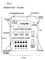
- FIG. 3is an example of a top plan view of one variation of the receiver/tuner units constructed in accordance with the preferred embodiments of the present invention.
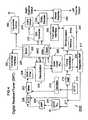
- FIG. 4is a block diagram of the receiver/tuner of the system.
- the problems of providing digital audio and display of corresponding program information associated with a digital music serviceare solved by the principles of the present invention.
- the present inventionensures that a listener will continue to enjoy the advantages of digital audio, while also enabling portable reception of the service within a localized setting.
- the inventionprovides a means for the user to participate in music surveys, store desired program information, and purchase of music via electronic accounts, by combing a wireless receiver/tuner unit that communicates with and controls a first controlled device, such as a digital audio and program information transmitter unit.
- a system constructed in accordance with the present inventionis comprised of two primary components, a transmitter and at least one receiver/tuner.
- the transmitterserves as an addressable controller that includes input means, encoders/decoders associated with the system, demultiplexer, service codes, converter means, carrier signal producing means, combining means, and antenna means.
- the convertercontains a digital to RF (radio frequency) converter module, demodulator, addressable control interface logic, subscriber interface logic, and decryptor.
- the input meansis arranged for receiving a multiplexed serial digital data audio/program information stream that includes a plurality of the digital audio, program information, and national subscriber information signals from said multiplexed serial stream.
- the carrier signal producing meansis arranged for providing at least a first group of carrier signals, with that group comprising a set of different carrier signals.
- Each of the carrier signals of the groupis preselected and is different from the others of the group, and is at a frequency of at least 900 mHz.
- the modulating meansis coupled to the input means for modulating the carrier signals of the first group with respective ones of the plurality of input signals to produce a plurality of modulated carrier signals.
- the serial streamis modulated using multiphase or multilevel amplitude or frequency modulation of the carrier in the F.M. broadcast band.
- the means for combiningis coupled to the modulating means for combing the modulated carrier signals into a combined signal and for providing the combined signal to the antenna means.
- the antenna meansradiates the combined signal over the air.
- the receiver/tuneris a device consisting of subcomponents including a microprocessor, addressable controller interface logic, RF to digital converter, signal amplifier, tuning synthesizer, subscriber interface logic, LCD display, demodulator, local oscillator, keypad interface, and output amplifier.
- the receiver meansis arranged for receiving the combined signal and for demodulating a selected one of the carrier signals in the group so that the input signal is extracted therefrom for reproduction by transducer means coupled to the receiver means.
- the transmitter meansprovides plural groups of different carrier signals comprising plural carrier signals which are different from the other signals in that group and from the carrier signals in the other groups and are of a frequency of at least 900 mHz.
- First user-selectable meansare provided in the transmitter means and in the receiver means to select a desired group of carrier frequencies for system operation.
- Second user-selectable meansare provided in the receiver means to enable the user to select a desired carrier frequency of the selected group to be demodulated so that they can hear the digital audio and view the program information signal extracted therefrom by such demodulation.
- the multiple groups of carrier frequencies availableenables a selection of a group of carrier frequencies which are different from those which may be used by another like system operation within the operating range of the system to ensure that there will be no interference by that other system.
- a delivery system 10such as coaxial cable, satellite, the Internet, microwave, and etc., outputs a serial digital audio/program information stream 22 that contains digital audio, program information, and national subscriber information.
- the transmitter 100receives the said serial digital data stream 22 and demultiplexes, decrypts, and decodes the digital audio and program information signal.
- the digital audio signal and program informationare converted to a digital RF carrier frequencies and broadcasted to a plurality of second devices, preferably at least one receiver/tuner unit 200 , more fully described with respect of FIGS. 3-4 , that outputs the selected audio electronically and displays the corresponding program information of the audio track currently listened to by the subscriber.
- FIG. 2is a block diagram of the preferred digital music transmitter (DMT) 100 .
- the serial digital data stream 22is passed via an established system of digital data distribution 10 , for example, multisystem operators coaxial cable or direct broadcast satellite, and is received by the transmitter input terminal 105 .
- the transmitter input terminal 105preferably includes phase-lock loop (PLL) circuitry.
- PLLphase-lock loop
- the signalis amplified by an amplifier 110 and filtered by a SAW filter 115 before being demodulated by a demodulator 120 .
- the demodulator 120converts the selected digital frequency to demodulation intermediate frequency (IF).
- IFdemodulation intermediate frequency
- the output of the demodulator 120is quadrature partial response (QpR) demodulated to produce a 5.6 Mbps data stream containing 150 stereo pairs of digital audio data to an applications specific integrated circuit (ASIC) 130 .
- the demodulator 120provides data to a data clock recovery PLL 125 .
- the data clock recovery PLL 125contains a 33.8688 mHz crystal 122 (about 33.9 mHz) for timing purposes.
- the ASIC 130provides demultiplexing, decrypting, and decoding operations upon the 5.6 Mbps data stream input by the demodulator 120 to the microprocessor 140 .
- the ASIC 130separates the 5.6 Mbps data stream to a select one of 150 stereo pairs of digital audio signals.
- the selected stereo pairis decrypted and separated to provide digital audio signal and a program information signal.
- the digital audio signalis then decoded according to a variety of known techniques.
- the ASIC 130inputs the digital audio signals, provided at a sampling rate of 44.1 kilohertz (KHz), to a digital RF converter 150 .
- the audio signalsare provided to a F.M. stereo encoder and loudness processor 152 , and then to F.M. band exciter 154 .
- the output of the exciter 154is amplified by a high power amplifier 156 and broadcast over the airwaves by an antenna 160 as digital F.M. in the F.M. broadcast for reception by a digital F.M. receiver 201 , such as disclosed in FIG. 3
- a clock signal generated internal to the ASIC 130is utilized as a carrier signal to switch the output of the DRT 200 ON or OFF at a frequency of 44.1 KHz.
- the 44.1 KHz clock from an ASIC Clock generator 130 amay be utilized to generate a carrier signal for RF signals sent by the DRT transmitter 160 .
- the ASIC Clock signal provided by the ASIC clock 130 ais derived from the about 33.9 mHz signal provided to the ASIC 130 by the data clock PLL 125 .
- the DRT 200operates to control selected function of the transmitter as well as the program information transmitted by the DRT transmitter 160 associated with the DMT 100 .
- the ASIC Clock signal provided by the ASIC clock 130is derived from the about 33.9 mHz signal provided to the ASIC 150 by the data clock PLL 125 . Specifically, the ASIC Clock signal is derived by dividing the 33.9 mHz signal by three (3) to provide a second clock signal having a frequency of 11.3 mHz, and by then dividing the 11.3 mHz signal to the preferred fixed first frequency for the 44.1 kHz ASIC Clock signal.
- the 11.3 mHz clock signalis utilized as a clock signal selected operations conducted by the ASIC 130 .
- the ASIC 130contains a synchronizing circuit 132 which is utilized to provide clock synchronized program information signals to the DRT 200 .
- the synchronizing circuit 132operated to provide two separate timing alignment functions. First, the synchronizing circuit 132 aligns the program information signal provided by the microprocessor to the 11.3 mHz clock signal. Second, the synchronizing circuit 132 aligns the 44.1 KHz ASIC Clock signal to the 11.3 mHz clock
- the synchronizing circuit 132includes a first synchronizing element 133 , an, edge detector 134 , and second synchronized element 135 , and gate 136 .
- the microprocessor 140provides program information signals in the form of a serial data signal formatted in the appropriate display information protocol to the first synchronizing element 133 .
- the microprocessor 140outputs the program information signals to the first synchronizing element 133 at a predefined data rate, preferably 4900 baud.
- the 11.3 mHz clock signalis provided as another input to the first synchronized element 133 .
- the first synchronizing element 133aligns the rising edge of the program information signals to the 11.3 mHz clock signal to provide an output signal synchronized with the 11.3 mHz clock.
- the second synchronizing element 135accepts the synchronized output signal of the first synchronizing element 133 and produces a gate signal when the output signal of the edge detector 134 enables the second synchronizing element 135 .
- the gate signal produced by the second synchronizing element 135 and the ASIC clock signal of 44.1 kHzare provided as inputs to an AND gate 136 . Accordingly, the integral number of cycles of the ASIC clock signal output by the AND gate 136 is effectively determined by the pulse width or pulse duration of the gate signal output by the second synchronizing element 135 .
- the output of the ASIC 130is a carrier-modulated program information signal, produced by an on/off keying technique, and is provided from the synchronizing circuit 130 on line 137 to the DRT transmitter 160 .
- the carrier-modulated program information signalwhen formatted with appropriate start bits, stop bits, and other formatting information described below, comprises a display information signal that is ultimately display as alphanumeric characters on the display of the DRT 200 .
- the DRT transmitter 160is responsive to the carrier-modulated program information signal provided on line 137 .
- the microprocessor 140initiates a transmission of a program information signal by the DMT 100 .
- the ASIC 130outputs the synchronized program information signal at the rate defined by the first frequency (44.1 KHz) to the DRT transmitter 160 .
- the DRT receiver 170includes a demodulator 172 and RF diode 174 .
- the RE diode 174is located between an input of the demodulator 172 and the ground.
- the RF diode 174detects a command signal from the DRT 200 .
- the RF diode 174outputs a detected signal to the demodulator 172 .
- the demodulator 172demodulates and filters the detected RF signal and provides an output voltage signal to the receiver input terminal of the microprocessor 140 on line 173 .
- the demodulator 172provided the specific functions preamplification, bandpass filtering, and detection of the detected RF signal provided by the RF diode 174 .
- FIG. 4is a block diagram of the preferred digital receiver/tuner (DRT) unit 200 .
- the preferred DRT unitsinclude a display for the control of the digital music transmitter (DMT) 100 .
- the top surface of the DRT 200includes an alphanumeric character display and a matrix of contact switches forming a keypad. Each contact switch of the keypad is covered by a push button or key that includes a label which defines the function or instruction initiated when the user presses the push button.
- selected areas of the tip surface of the DRT unitinclude labels or other indicia that further designate the function or instruction associated with the key or push button.
- the usercan control the functions of the DMT 100 in a manner similar to the use of currently popular wireless transmitter/receiver units that control the functions of consumer products, such as cordless telephones or local audio signal transmitter.
- the DMT 100remains in a dormant mode with a transmitted passive signal that responds to a selected command function from the DRT unit 200 .
- the usercan initiate or terminate transmission of the digital audio and program information from the DMT 100 by pressing a selected key.
- Each of the buttons or key of the keypadis labeled to indicate the function associated with the key.
- a usercan select one of the available digital audio and program information channels transmitted by the DMT 100 for the listening pleasure of the subscriber.
- the keys labeled TUNE (up arrow) and TUNE (down arrow)may be used by the listener to increment or decrement the digital audio and program information channels transmitted by the DMT 100 .
- a volume up (VOL up arrow) and a volume down (VOL down arrow) keyscan be utilized to control the volume level provided by the DMT 100 .
- An ON/OFF key with a power indicator lightmay be utilized by the listener to either power on or off the DRT 200 and DMT 100 signal transmission.
- a MUTE keyis useful for eliminating the audible portion of the program provided by the DMT 100 .
- control function related to the control of the DMT 100 by the DRT unit 200include control functions associated with the keys ENTER/NEXT. PRESET and MODE. By pressing the ENTER/NEXT key, the user initiates a command function that may be associated with the various functions of the DRT unit 200 .
- the PRESET keypermits the user to store a favorite digital audio channel for future operations by the DRT unit 200 .
- the MODE functionchanges the message field on the LCD viewscreen according to selected function by the user, for example viewing or storing program information for a current music selection, participating in music surveys, or purchase of music via electronic account.
- the listenercan also review the program information associated with a current program by inputting an information request for transmission to the DMT 100 .
- the userBy pressing the VIEW key, the user initiates the transmission of an information request by the DRT unit 200 to the DMT 100 .
- the DMTprocesses the information request and initiates a search for program information associated with the current program. If the program information is not found by the DMT within a predetermined timer period, typically about five seconds, the DMT 100 will respond to the transmitted information request by transmitting an error message to the DRT unit 200 . If the search by the DMT 100 is successful, the DMT 100 will respond to the transmitted information request by transmitting the program information to the DRT unit 200 .
- a typical program messageincludes information concerning the composer, the track title, the artist, the album associated with the track title, and custom information concerning the current performance.
- the preferred DRT unit 200includes a processor 240 , preferably a microcomputer or microcontroller, having on-board mask programmed memory, such as a read only memory (ROM) 240 a .
- the memory 205 acomprises plurality of memory locations for storing parameters associated with different control signal protocols (in particular, for storing a plurality of parameters associated with different control protocols for different controllable devices).
- the preferred DRT unit 200further includes a RF receiver 201 , demodulator 218 , an applications specific integrated circuit ASIC 230 , digital/audio converter 270 , transmitter 260 , a data clock recovery PLL 225 , front panel interface 250 , stereo output amplifier 280 .
- the output of the demodulator 218is quadrature partial response (QpR) demodulated to produce a 5.6 Mbps data stream containing 150 stereo pair of digital audio data to the ASIC 230 .
- the demodulatorprovides data to a data clock recovery PLL 225 .
- the data clock recovery PLL 225contains a 33.8688 mHz crystal 122 (about 33.9 mHz) for timing purposes.
- the DMT 100 control signal protocolsare stored in the ROM 240 a .
- the control protocolincludes the properly formatted codes associated with control functions for the DMT 100 .
- the ASIC 230provides demultiplexing, decrypting, and decoding operations upon the 5.6 Mbps data stream input by the demodulator 218 to the microprocessor 170 .
- the ASIC 230separates the 5.6 Mbps data stream to a select one of 150 stereo pairs of digital audio signals. The selected stereo pair is decrypted and separated to provide a program information signal and a digital audio signal. The digital audio signal is then decoded according to a variety of known techniques.
- the ASIC 230inputs the digital audio and program information signals, provided at a sampling rate of 44.1 kHz, to a digital/audio converter 270 , transmitter control 260 , and microprocessor memory 240 a .
- the demultiplexed control and channel data separated out from the data steam by the ASIC 230are provided to a microprocessor 240 which controls the overall operation of the DRT unit 200 .
- a clock signal generated internal to the ASIC 230is utilized as a carrier signal to switch the output of the DRT 200 ON or OFF at a frequency of 44.1 KHz.
- the 44.1 KHz clock from an ASIC Clock generator 230 amay be utilized to generate a carrier signal for RF signals sent by the DRT transmitter 160 .
- the ASIC Clock signal provided by the ASIC clock 230 ais derived from the about 33.9 mHz signal provided to the ASIC 230 by the data clock PLL 225 .
- the DRT 200operates to control selected functions of the DMT 100 as well as the program information transmitted by the DRT transmitter 260 associated with the DMT 100 . Referring to FIG.
- the ASIC Clock signal provided by the ASIC clock 230 ais similar in function and purpose to that of the aforementioned ASIC clock 130 a .
- the 11.3 mHz clock signalis utilized as a clock signal selected operations conducted by the ASIC 230 .
- digital audio and program information carrier signalsare received by the receiver antenna 201 from the DMT transmitter 160 .
- the received signalis provided to a double tuned tracking filter (DTTF) with PLL circuitry, from there to an amplifier 203 , on to a single tuned tracking filter (STTF) 205 , a mixer 207 , and SAW filter 209 , and into a demodulator 218 , according to known techniques.
- DTTFdouble tuned tracking filter
- STTFsingle tuned tracking filter
- SAW filter 209single tuned tracking filter
- the channel selection processis under control of a tuning synthesizer 220 , integrating amplifier 217 , STTF 215 , and amplifier 212 , interconnected as shown and impressing an appropriate signal on a line 211 to the DTTF 201 , STTF 205 , and oscillator 210 to effect channel selection, according to known techniques.
- the program information signal from the ASIC 230is sent to the microprocessor 240 where it may be displayed on the front panel interface 250 .
- the ASIC 230also sends the program information signal to the transmitter interface 255 and transmitter control 260 for transmission to the DMT 100 .
- Channel selectionis provided by the infrared receiver and/or front panel interface 250 , which information is passed on by the microprocessor 240 to the tuning synthesizer 220 .
- the ASIC 230inputs the digital audio and program information signals, provided at a sampling rate of 44.1 kHz to a digital/audio converter 270 .
- the output of the D/A 270 deviceis provided as a data stream over a bus to a logic circuit 274 with separates the dates stream into control bits and channel indication (tag bits) and encrypted digital audio bits (demultiplexing functions) and decrypts the digitized audio data into a suitable form for a Dolby decoder 278 .
- the audio datais decrypted into three serial streams per audio channel consisting of basic delta modulation parameters for “left” and “right” channels.
- the output of the Dolby decoder 278is provided as “left” and “right” audio channels to a stereo amplifier 280 , and to stereo outputs for use with standard audio components.
- the present inventionovercomes the disadvantages of the prior art and achieves the objects and advantages of the invention recited above. Accordingly, the invention improves existing methods of providing digital music by making the service more convenient and accessible to subscribers through wireless transmission of music to remotely located devices. Greater recognition among subscribers is gained by similarities of the preferred embodiments to more popular consumer electronic music devices. And, digital music is made more versatile with improved methods of subscriber interaction with the service.
- the above description of the inventionis intended to be illustrative and not limiting. Various changes or modifications in the embodiments described may occur to those skilled in the art and these can be made without departing from the spirit or the scope of the invention.
Landscapes
- Engineering & Computer Science (AREA)
- Theoretical Computer Science (AREA)
- General Engineering & Computer Science (AREA)
- Physics & Mathematics (AREA)
- General Physics & Mathematics (AREA)
- Signal Processing (AREA)
- Business, Economics & Management (AREA)
- Multimedia (AREA)
- Accounting & Taxation (AREA)
- Human Computer Interaction (AREA)
- Strategic Management (AREA)
- Finance (AREA)
- Data Mining & Analysis (AREA)
- Development Economics (AREA)
- Databases & Information Systems (AREA)
- General Business, Economics & Management (AREA)
- Entrepreneurship & Innovation (AREA)
- Library & Information Science (AREA)
- Game Theory and Decision Science (AREA)
- Economics (AREA)
- Marketing (AREA)
- Computer Networks & Wireless Communication (AREA)
- Health & Medical Sciences (AREA)
- Audiology, Speech & Language Pathology (AREA)
- General Health & Medical Sciences (AREA)
- Automation & Control Theory (AREA)
- Circuits Of Receivers In General (AREA)
- Transmitters (AREA)
Abstract
Description
Claims (20)
Priority Applications (4)
| Application Number | Priority Date | Filing Date | Title |
|---|---|---|---|
| US13/101,841US8265545B2 (en) | 1996-07-15 | 2011-05-05 | Wireless environment method and apparatus |
| US13/507,835US20140214188A1 (en) | 1996-07-15 | 2012-07-31 | Method and apparatus for wireless digital radio |
| US14/490,407US20150004900A1 (en) | 1996-07-15 | 2014-09-18 | Method and apparatus for wireless digital radio |
| US14/603,114US20150169281A1 (en) | 1996-07-15 | 2015-01-22 | Method and apparatus for wireless digital radio |
Applications Claiming Priority (6)
| Application Number | Priority Date | Filing Date | Title |
|---|---|---|---|
| US2172196P | 1996-07-15 | 1996-07-15 | |
| US08/886,951US6212359B1 (en) | 1996-07-15 | 1997-07-02 | Wireless Transceiver System For Digital Music |
| US09/798,331US6757913B2 (en) | 1996-07-15 | 2001-03-01 | Wireless music and data transceiver system |
| US10/878,731US7502604B2 (en) | 1996-07-15 | 2004-06-28 | Wireless environment method and apparatus |
| US12/363,593US7962090B2 (en) | 1996-07-15 | 2009-01-30 | Method and apparatus for satellite digital audio |
| US13/101,841US8265545B2 (en) | 1996-07-15 | 2011-05-05 | Wireless environment method and apparatus |
Related Parent Applications (1)
| Application Number | Title | Priority Date | Filing Date |
|---|---|---|---|
| US12/363,593ContinuationUS7962090B2 (en) | 1996-07-15 | 2009-01-30 | Method and apparatus for satellite digital audio |
Related Child Applications (1)
| Application Number | Title | Priority Date | Filing Date |
|---|---|---|---|
| US13/507,835ContinuationUS20140214188A1 (en) | 1996-07-15 | 2012-07-31 | Method and apparatus for wireless digital radio |
Publications (2)
| Publication Number | Publication Date |
|---|---|
| US20110257774A1 US20110257774A1 (en) | 2011-10-20 |
| US8265545B2true US8265545B2 (en) | 2012-09-11 |
Family
ID=25173133
Family Applications (7)
| Application Number | Title | Priority Date | Filing Date |
|---|---|---|---|
| US09/798,331Expired - LifetimeUS6757913B2 (en) | 1996-07-15 | 2001-03-01 | Wireless music and data transceiver system |
| US10/878,731Expired - Fee RelatedUS7502604B2 (en) | 1996-07-15 | 2004-06-28 | Wireless environment method and apparatus |
| US12/363,593Expired - Fee RelatedUS7962090B2 (en) | 1996-07-15 | 2009-01-30 | Method and apparatus for satellite digital audio |
| US13/101,841Expired - Fee RelatedUS8265545B2 (en) | 1996-07-15 | 2011-05-05 | Wireless environment method and apparatus |
| US13/507,835AbandonedUS20140214188A1 (en) | 1996-07-15 | 2012-07-31 | Method and apparatus for wireless digital radio |
| US14/490,407AbandonedUS20150004900A1 (en) | 1996-07-15 | 2014-09-18 | Method and apparatus for wireless digital radio |
| US14/603,114AbandonedUS20150169281A1 (en) | 1996-07-15 | 2015-01-22 | Method and apparatus for wireless digital radio |
Family Applications Before (3)
| Application Number | Title | Priority Date | Filing Date |
|---|---|---|---|
| US09/798,331Expired - LifetimeUS6757913B2 (en) | 1996-07-15 | 2001-03-01 | Wireless music and data transceiver system |
| US10/878,731Expired - Fee RelatedUS7502604B2 (en) | 1996-07-15 | 2004-06-28 | Wireless environment method and apparatus |
| US12/363,593Expired - Fee RelatedUS7962090B2 (en) | 1996-07-15 | 2009-01-30 | Method and apparatus for satellite digital audio |
Family Applications After (3)
| Application Number | Title | Priority Date | Filing Date |
|---|---|---|---|
| US13/507,835AbandonedUS20140214188A1 (en) | 1996-07-15 | 2012-07-31 | Method and apparatus for wireless digital radio |
| US14/490,407AbandonedUS20150004900A1 (en) | 1996-07-15 | 2014-09-18 | Method and apparatus for wireless digital radio |
| US14/603,114AbandonedUS20150169281A1 (en) | 1996-07-15 | 2015-01-22 | Method and apparatus for wireless digital radio |
Country Status (8)
| Country | Link |
|---|---|
| US (7) | US6757913B2 (en) |
| EP (1) | EP1410539A1 (en) |
| JP (1) | JP2004532541A (en) |
| KR (1) | KR20030093225A (en) |
| BR (1) | BR0207801A (en) |
| CA (1) | CA2440034A1 (en) |
| MX (1) | MXPA03007906A (en) |
| WO (1) | WO2002071664A1 (en) |
Cited By (1)
| Publication number | Priority date | Publication date | Assignee | Title |
|---|---|---|---|---|
| US20140214188A1 (en)* | 1996-07-15 | 2014-07-31 | Gregory Knox | Method and apparatus for wireless digital radio |
Families Citing this family (68)
| Publication number | Priority date | Publication date | Assignee | Title |
|---|---|---|---|---|
| US8516132B2 (en) | 1997-06-19 | 2013-08-20 | Mymail, Ltd. | Method of accessing a selected network |
| US6571290B2 (en) | 1997-06-19 | 2003-05-27 | Mymail, Inc. | Method and apparatus for providing fungible intercourse over a network |
| WO1999025082A1 (en)* | 1997-11-11 | 1999-05-20 | Sony Corporation | Transmitter and transmitting method, information editor and editing method, receiver and receiving method, information storage and storing method, and broadcasting system |
| AU8567798A (en) | 1998-06-19 | 2000-01-05 | Netsafe, Inc. | Method and apparatus for providing connections over a network |
| US6600908B1 (en) | 1999-02-04 | 2003-07-29 | Hark C. Chan | Method and system for broadcasting and receiving audio information and associated audio indexes |
| US20020104095A1 (en)* | 2000-10-06 | 2002-08-01 | Loc Nguyen | On-remote-control email and other service indicator methods, systems, and devices |
| US20020157115A1 (en)* | 2001-04-24 | 2002-10-24 | Koninklijke Philips Electronics N.V. | Wireless communication point of deployment module for use in digital cable compliant devices |
| US7512380B2 (en)* | 2001-08-17 | 2009-03-31 | Intel Corporation | Apparatus and methods for finding and using available transmission frequencies |
| US7558326B1 (en)* | 2001-09-12 | 2009-07-07 | Silicon Image, Inc. | Method and apparatus for sending auxiliary data on a TMDS-like link |
| FI114368B (en)* | 2002-03-12 | 2004-09-30 | Jutel Oy | Procedure and server for sending an audio message |
| US8549574B2 (en) | 2002-12-10 | 2013-10-01 | Ol2, Inc. | Method of combining linear content and interactive content compressed together as streaming interactive video |
| US20040117442A1 (en)* | 2002-12-10 | 2004-06-17 | Thielen Kurt R. | Handheld portable wireless digital content player |
| US9446305B2 (en) | 2002-12-10 | 2016-09-20 | Sony Interactive Entertainment America Llc | System and method for improving the graphics performance of hosted applications |
| US9108107B2 (en) | 2002-12-10 | 2015-08-18 | Sony Computer Entertainment America Llc | Hosting and broadcasting virtual events using streaming interactive video |
| US7493078B2 (en)* | 2002-12-10 | 2009-02-17 | Onlive, Inc. | Antenna assembly for satellite and wireless services |
| US7558525B2 (en) | 2002-12-10 | 2009-07-07 | Onlive, Inc. | Mass storage repository for a wireless network |
| US9077991B2 (en) | 2002-12-10 | 2015-07-07 | Sony Computer Entertainment America Llc | System and method for utilizing forward error correction with video compression |
| US7684752B2 (en)* | 2002-12-10 | 2010-03-23 | Onlive, Inc. | Wireless network providing distributed video / data services |
| US8964830B2 (en) | 2002-12-10 | 2015-02-24 | Ol2, Inc. | System and method for multi-stream video compression using multiple encoding formats |
| US9314691B2 (en) | 2002-12-10 | 2016-04-19 | Sony Computer Entertainment America Llc | System and method for compressing video frames or portions thereof based on feedback information from a client device |
| US9061207B2 (en) | 2002-12-10 | 2015-06-23 | Sony Computer Entertainment America Llc | Temporary decoder apparatus and method |
| US7849491B2 (en) | 2002-12-10 | 2010-12-07 | Onlive, Inc. | Apparatus and method for wireless video gaming |
| US9192859B2 (en) | 2002-12-10 | 2015-11-24 | Sony Computer Entertainment America Llc | System and method for compressing video based on latency measurements and other feedback |
| US20040110468A1 (en)* | 2002-12-10 | 2004-06-10 | Perlman Stephen G. | Wireless network with presentation and media layers for broadcast satellite and cable services |
| US8526490B2 (en) | 2002-12-10 | 2013-09-03 | Ol2, Inc. | System and method for video compression using feedback including data related to the successful receipt of video content |
| US20090118019A1 (en) | 2002-12-10 | 2009-05-07 | Onlive, Inc. | System for streaming databases serving real-time applications used through streaming interactive video |
| US10201760B2 (en) | 2002-12-10 | 2019-02-12 | Sony Interactive Entertainment America Llc | System and method for compressing video based on detected intraframe motion |
| US9138644B2 (en) | 2002-12-10 | 2015-09-22 | Sony Computer Entertainment America Llc | System and method for accelerated machine switching |
| US8711923B2 (en) | 2002-12-10 | 2014-04-29 | Ol2, Inc. | System and method for selecting a video encoding format based on feedback data |
| US8366552B2 (en) | 2002-12-10 | 2013-02-05 | Ol2, Inc. | System and method for multi-stream video compression |
| US7590084B2 (en)* | 2003-02-14 | 2009-09-15 | Onlive, Inc. | Self-configuring, adaptive, three-dimensional, wireless network |
| US7593361B2 (en)* | 2003-02-14 | 2009-09-22 | Onlive, Inc. | Method of operation for a three-dimensional, wireless network |
| US7215660B2 (en) | 2003-02-14 | 2007-05-08 | Rearden Llc | Single transceiver architecture for a wireless network |
| US7046999B2 (en)* | 2003-05-30 | 2006-05-16 | Nasaco Electronics (Hong Kong) Ltd. | Half-duplex wireless audio communication system |
| US8615157B1 (en) | 2003-11-17 | 2013-12-24 | David C. Isaacson | System and method for on-demand storage of randomly selected data |
| US8588582B2 (en)* | 2003-11-17 | 2013-11-19 | Diana Lynn Fitzgerald | System and method for on-demand storage of randomly selected data |
| US20050159125A1 (en)* | 2004-01-16 | 2005-07-21 | Luca Lodolo | One or more openly visible indicators that display wireless network signal strength |
| CN1328653C (en)* | 2004-03-19 | 2007-07-25 | 郦东 | Method and system of hand writing input on portable terminal |
| US8797926B2 (en) | 2004-06-04 | 2014-08-05 | Apple Inc. | Networked media station |
| US20070110074A1 (en)* | 2004-06-04 | 2007-05-17 | Bob Bradley | System and Method for Synchronizing Media Presentation at Multiple Recipients |
| US10972536B2 (en) | 2004-06-04 | 2021-04-06 | Apple Inc. | System and method for synchronizing media presentation at multiple recipients |
| US8443038B2 (en) | 2004-06-04 | 2013-05-14 | Apple Inc. | Network media device |
| US20060160486A1 (en)* | 2005-01-14 | 2006-07-20 | Xm Satellite Radio, Inc. | Method and system for converting streaming digital data to FM modulated data |
| KR100735233B1 (en)* | 2005-02-25 | 2007-07-03 | 삼성전자주식회사 | Personal Broadcasting Service Provision System |
| US9507919B2 (en)* | 2005-04-22 | 2016-11-29 | Microsoft Technology Licensing, Llc | Rights management system for streamed multimedia content |
| US7684566B2 (en) | 2005-05-27 | 2010-03-23 | Microsoft Corporation | Encryption scheme for streamed multimedia content protected by rights management system |
| US7848736B2 (en)* | 2006-01-18 | 2010-12-07 | Sms.Ac, Inc. | Package billing for micro-transactions |
| US20070028271A1 (en)* | 2005-07-26 | 2007-02-01 | Samsung Electronics Co., Ltd. | Apparatus for receiving digital multimedia broadcasting and method for outputting audio using the same |
| US8321690B2 (en)* | 2005-08-11 | 2012-11-27 | Microsoft Corporation | Protecting digital media of various content types |
| US8311048B2 (en)* | 2008-05-09 | 2012-11-13 | Roundbox, Inc. | Datacasting system with intermittent listener capability |
| JP2008005304A (en)* | 2006-06-23 | 2008-01-10 | Toshiba Corp | Copyright protection system, copyright protection device and video processing device |
| US8041292B2 (en) | 2006-12-04 | 2011-10-18 | Ibiquity Digital Corporation | Network radio receiver |
| US8409006B2 (en) | 2007-09-28 | 2013-04-02 | Activision Publishing, Inc. | Handheld device wireless music streaming for gameplay |
| US9168457B2 (en) | 2010-09-14 | 2015-10-27 | Sony Computer Entertainment America Llc | System and method for retaining system state |
| US8477960B2 (en)* | 2009-06-04 | 2013-07-02 | Wavrydr, L.L.C. | System for allowing selective listening on multiple televisions |
| US9432442B2 (en)* | 2009-10-02 | 2016-08-30 | Ncomputing Inc. | System and method for a graphics terminal multiplier |
| WO2011132398A1 (en)* | 2010-04-20 | 2011-10-27 | パナソニック株式会社 | Input/output switching device and input/output switching method |
| KR101087082B1 (en) | 2011-05-02 | 2011-11-25 | 제이엠씨엔지니어링 주식회사 | Wireless speaker and wireless speaker system |
| US9294158B2 (en)* | 2012-08-07 | 2016-03-22 | Broadcom Corporation | Broadcast audio service |
| CN104901009A (en)* | 2015-04-29 | 2015-09-09 | 成都中兢伟奇科技有限责任公司 | Digital terminal antenna box supporting multiple satellite televisions |
| US11297369B2 (en) | 2018-03-30 | 2022-04-05 | Apple Inc. | Remotely controlling playback devices |
| US10783929B2 (en) | 2018-03-30 | 2020-09-22 | Apple Inc. | Managing playback groups |
| US10993274B2 (en) | 2018-03-30 | 2021-04-27 | Apple Inc. | Pairing devices by proxy |
| GB201805628D0 (en) | 2018-04-05 | 2018-05-23 | Qatar Found Education Science & Community Dev | Method and system for data specific transceiver design for efficient ioT devices |
| US10614857B2 (en) | 2018-07-02 | 2020-04-07 | Apple Inc. | Calibrating media playback channels for synchronized presentation |
| US11604824B2 (en)* | 2019-11-25 | 2023-03-14 | Mohammed Mizan Rahman | System and method of managing user engagement with a musical playlist |
| JP7436280B2 (en)* | 2020-05-11 | 2024-02-21 | ローランド株式会社 | Performance program and performance device |
| US20250132908A1 (en)* | 2023-10-20 | 2025-04-24 | Dell Products L.P. | Secure communication in edge clusters using audio communications |
Citations (2)
| Publication number | Priority date | Publication date | Assignee | Title |
|---|---|---|---|---|
| US6212359B1 (en)* | 1996-07-15 | 2001-04-03 | Gregory D. Knox | Wireless Transceiver System For Digital Music |
| US6757913B2 (en)* | 1996-07-15 | 2004-06-29 | Gregory D. Knox | Wireless music and data transceiver system |
Family Cites Families (135)
| Publication number | Priority date | Publication date | Assignee | Title |
|---|---|---|---|---|
| US4541091A (en) | 1982-06-11 | 1985-09-10 | Hitachi, Ltd. | Code error detection and correction method and apparatus |
| US4591929A (en) | 1984-07-13 | 1986-05-27 | Newsom Harley M | Interactive learning programming and like control circuitry |
| US4758903A (en) | 1984-11-22 | 1988-07-19 | Hitachi, Ltd. | Apparatus for recording and reproducing video signal and digital signal other than video signal |
| US4684898A (en) | 1985-05-15 | 1987-08-04 | Signetics Corporation | Temperature and process variation compensation for a delta demodulation decoder |
| US5195092A (en) | 1987-08-04 | 1993-03-16 | Telaction Corporation | Interactive multimedia presentation & communication system |
| DE3744075A1 (en) | 1987-12-24 | 1989-07-13 | Licentia Gmbh | METHOD FOR EQUALIZING DISPERSIVE, LINEAR OR APPROXIMATELY LINEAR CHANNELS FOR TRANSMITTING DIGITAL SIGNALS, AND ARRANGEMENT FOR CARRYING OUT THE METHOD |
| US4881241A (en) | 1988-02-24 | 1989-11-14 | Centre National D'etudes Des Telecommunications | Method and installation for digital communication, particularly between and toward moving vehicles |
| US4905094A (en) | 1988-06-30 | 1990-02-27 | Telaction Corporation | System for audio/video presentation |
| US5191576A (en) | 1988-11-18 | 1993-03-02 | L'Etat Francais and Telediffusion de France S.A. | Method for broadcasting of digital data, notably for radio broadcasting at high throughput rate towards mobile receivers, with time frequency interlacing and analog synchronization |
| EP0389689B1 (en) | 1989-03-28 | 1997-06-04 | POLYGRAM MANUFACTURING & DISTRIBUTION CENTRES GMBH | Method for transmitting a transmission signal and a transmitting device and a receiving device for use in the method |
| EP0394976B1 (en) | 1989-04-27 | 1995-11-29 | Matsushita Electric Industrial Co., Ltd. | Data companding method and data compressor/expander |
| NL9000338A (en) | 1989-06-02 | 1991-01-02 | Koninkl Philips Electronics Nv | DIGITAL TRANSMISSION SYSTEM, TRANSMITTER AND RECEIVER FOR USE IN THE TRANSMISSION SYSTEM AND RECORD CARRIED OUT WITH THE TRANSMITTER IN THE FORM OF A RECORDING DEVICE. |
| US5592352A (en) | 1989-06-26 | 1997-01-07 | U.S. Philips Corporation | System for recording/reproducing signals on/from a magnetic tape in a cassette |
| US5185800A (en) | 1989-10-13 | 1993-02-09 | Centre National D'etudes Des Telecommunications | Bit allocation device for transformed digital audio broadcasting signals with adaptive quantization based on psychoauditive criterion |
| US5051822A (en) | 1989-10-19 | 1991-09-24 | Interactive Television Systems, Inc. | Telephone access video game distribution center |
| NL9001203A (en) | 1989-12-18 | 1991-07-16 | Philips Nv | SYSTEM FOR RECORDING / DISPLAYING SIGNALS ON TAPES CONTAINED IN CASSETTES. |
| NL9000039A (en) | 1990-01-08 | 1991-08-01 | Philips Nv | DIGITAL TRANSMISSION SYSTEM, TRANSMITTER AND RECEIVER FOR USE IN THE TRANSMISSION SYSTEM AND RECORD CARRIED OUT WITH THE TRANSMITTER IN THE FORM OF A RECORDING DEVICE. |
| US5179576A (en) | 1990-04-12 | 1993-01-12 | Hopkins John W | Digital audio broadcasting system |
| US5303393A (en)* | 1990-11-06 | 1994-04-12 | Radio Satellite Corporation | Integrated radio satellite response system and method |
| US5455823A (en) | 1990-11-06 | 1995-10-03 | Radio Satellite Corporation | Integrated communications terminal |
| US5291289A (en) | 1990-11-16 | 1994-03-01 | North American Philips Corporation | Method and apparatus for transmission and reception of a digital television signal using multicarrier modulation |
| US5282028A (en)* | 1990-11-27 | 1994-01-25 | Scientific-Atlanta, Inc. | Remote control for digital music terminal with synchronized communications |
| US5262858A (en) | 1990-12-05 | 1993-11-16 | Deutsche Itt Industries Gmbh | Method of converting the clock rate of a digitized signal |
| FR2670969B1 (en) | 1990-12-19 | 1993-04-16 | France Etat | TIME-FREQUENCY DISTRIBUTION DATA TRANSMISSION SYSTEM, WITH CHANNEL STRUCTURING. |
| US5132992A (en) | 1991-01-07 | 1992-07-21 | Paul Yurt | Audio and video transmission and receiving system |
| DE4102408A1 (en) | 1991-01-28 | 1992-08-06 | Grundig Emv | PROCESS FOR TRANSMITTER OR REGIONAL IDENTIFIER IN SAME-WAVE NETWORKS |
| US5408686A (en)* | 1991-02-19 | 1995-04-18 | Mankovitz; Roy J. | Apparatus and methods for music and lyrics broadcasting |
| US5278844A (en) | 1991-04-11 | 1994-01-11 | Usa Digital Radio | Method and apparatus for digital audio broadcasting and reception |
| US5315583A (en) | 1991-04-11 | 1994-05-24 | Usa Digital Radio | Method and apparatus for digital audio broadcasting and reception |
| DE4111855C2 (en) | 1991-04-11 | 1994-10-20 | Inst Rundfunktechnik Gmbh | Method for the radio transmission of a digitally coded data stream |
| US5278826A (en) | 1991-04-11 | 1994-01-11 | Usa Digital Radio | Method and apparatus for digital audio broadcasting and reception |
| US5333155A (en)* | 1991-04-25 | 1994-07-26 | Rohde & Schwarz Gmbh & Co. Kg | Method and system for transmitting digital audio signals from recording studios to the various master stations of a broadcasting network |
| FR2678437B1 (en) | 1991-06-28 | 1994-01-28 | France Telecom | MIXED ANTENNA FOR RECEIVING SIGNALS TRANSMITTED SIMULTANEOUSLY BY SATELLITE AND EARTH STATIONS, PARTICULARLY FOR RECEIVING DIGITAL SOUND BROADCASTING SIGNALS. |
| US5184347A (en)* | 1991-07-09 | 1993-02-02 | At&T Bell Laboratories | Adaptive synchronization arrangement |
| JP2973675B2 (en) | 1991-07-22 | 1999-11-08 | 日本電気株式会社 | Encoding / decoding system and apparatus suitable for variable rate transmission |
| DE4125606A1 (en) | 1991-08-02 | 1993-02-04 | Rohde & Schwarz | METHOD FOR TRANSMITTING DIGITAL HDTV SIGNALS |
| US5491839A (en)* | 1991-08-21 | 1996-02-13 | L. S. Research, Inc. | System for short range transmission of a plurality of signals simultaneously over the air using high frequency carriers |
| FR2680924B1 (en) | 1991-09-03 | 1997-06-06 | France Telecom | FILTERING METHOD SUITABLE FOR A SIGNAL TRANSFORMED INTO SUB-BANDS, AND CORRESPONDING FILTERING DEVICE. |
| US5247347A (en) | 1991-09-27 | 1993-09-21 | Bell Atlantic Network Services, Inc. | Pstn architecture for video-on-demand services |
| US5367638A (en) | 1991-12-23 | 1994-11-22 | U.S. Philips Corporation | Digital data processing circuit with control of data flow by control of the supply voltage |
| FR2686751B1 (en) | 1992-01-24 | 1997-03-28 | France Telecom | MAXIMUM LIKE-DECODING METHOD WITH SUB-SAMPLE DECODING MESH, AND CORRESPONDING DECODING DEVICE. |
| JP2904986B2 (en) | 1992-01-31 | 1999-06-14 | 日本放送協会 | Orthogonal frequency division multiplex digital signal transmitter and receiver |
| DE69331166T2 (en) | 1992-02-03 | 2002-08-22 | Koninklijke Philips Electronics N.V., Eindhoven | Transmission of digital broadband signals |
| US5684918A (en) | 1992-02-07 | 1997-11-04 | Abecassis; Max | System for integrating video and communications |
| US5610653A (en) | 1992-02-07 | 1997-03-11 | Abecassis; Max | Method and system for automatically tracking a zoomed video image |
| FR2687520B1 (en) | 1992-02-14 | 1994-05-06 | France Telecom | METHOD FOR IMPLANTING THE INFRASTRUCTURE OF A CELLULAR COMMUNICATION NETWORK. |
| US5539773A (en) | 1992-02-17 | 1996-07-23 | Thomson Consumer Electronics S.A. | Method and apparatus for ghost cancelling and/or equalizing |
| US5345599A (en) | 1992-02-21 | 1994-09-06 | The Board Of Trustees Of The Leland Stanford Junior University | Increasing capacity in wireless broadcast systems using distributed transmission/directional reception (DTDR) |
| DE4209544A1 (en) | 1992-03-24 | 1993-09-30 | Inst Rundfunktechnik Gmbh | Method for transmitting or storing digitized, multi-channel audio signals |
| US5282222A (en) | 1992-03-31 | 1994-01-25 | Michel Fattouche | Method and apparatus for multiple access between transceivers in wireless communications using OFDM spread spectrum |
| FR2690029B1 (en) | 1992-04-08 | 1995-03-31 | France Telecom | Method for transmitting digital paging data, and corresponding paging receiver. |
| US5703795A (en)* | 1992-06-22 | 1997-12-30 | Mankovitz; Roy J. | Apparatus and methods for accessing information relating to radio and television programs |
| DE4222623C2 (en) | 1992-07-10 | 1996-07-11 | Inst Rundfunktechnik Gmbh | Process for the transmission or storage of digitized sound signals |
| EP0584882A1 (en) | 1992-08-28 | 1994-03-02 | Philips Electronics Uk Limited | Loop antenna |
| US5359626A (en)* | 1992-09-02 | 1994-10-25 | Motorola, Inc. | Serial interface bus system for transmitting and receiving digital audio information |
| GB9218874D0 (en) | 1992-09-07 | 1992-10-21 | British Broadcasting Corp | Improvements relating to the transmission of frequency division multiplex signals |
| DE4306590A1 (en) | 1992-09-21 | 1994-03-24 | Rohde & Schwarz | Digital broadcast network system |
| DE4234015A1 (en) | 1992-10-09 | 1994-04-14 | Thomson Brandt Gmbh | Method and device for reproducing an audio signal |
| US5689245A (en) | 1992-10-19 | 1997-11-18 | Radio Satellite Corporation | Integrated communications terminal |
| US5425050A (en) | 1992-10-23 | 1995-06-13 | Massachusetts Institute Of Technology | Television transmission system using spread spectrum and orthogonal frequency-division multiplex |
| DE69312221T2 (en) | 1992-11-02 | 1997-10-30 | Matsushita Electric Ind Co Ltd | Channel selector for digitally modulated signals |
| DE4237692C1 (en) | 1992-11-07 | 1994-03-03 | Grundig Emv | Receiver for a digital broadcast signal |
| ES2159540T3 (en) | 1993-02-08 | 2001-10-16 | Koninkl Philips Electronics Nv | RECEIVER, WITH MULTIPLEXOR OF ORTOGONAL FREQUENCY DIVISION, WITH COMPENSATION FOR DIFFERENTIAL DELAYS. |
| US5905947A (en)* | 1993-03-04 | 1999-05-18 | Telefonaktiebolaget Lm Ericsson | Electronic audio system capable of communicating data signals over wireless networks |
| EP0616453B1 (en) | 1993-03-17 | 2000-05-31 | Koninklijke Philips Electronics N.V. | Receiver for differentially encoded PSK signals |
| US5577266A (en)* | 1993-04-08 | 1996-11-19 | Digital D.J. Inc. | Broadcast system with associated data capabilities |
| FR2704703B1 (en) | 1993-04-28 | 1995-06-30 | Gemplus Card Int | APPARATUS FOR EXPLOITING ELECTRIC SIGNALS. |
| DE4319315A1 (en) | 1993-06-11 | 1994-12-15 | Sel Alcatel Ag | Optical transmitter for the common transmission of analog signals and digital QAM signals |
| DE4319769C1 (en) | 1993-06-15 | 1994-07-14 | Grundig Emv | Method and arrangement for setting the local oscillators of a receiver in a multi-channel transmission system |
| SG43996A1 (en) | 1993-06-22 | 1997-11-14 | Thomson Brandt Gmbh | Method for obtaining a multi-channel decoder matrix |
| US5463641A (en) | 1993-07-16 | 1995-10-31 | At&T Ipm Corp. | Tailored error protection |
| US5509033A (en) | 1993-07-29 | 1996-04-16 | Chen; Xiao H. | Quadrature overlapping modulation system |
| US5808224A (en)* | 1993-09-03 | 1998-09-15 | Yamaha Corporation | Portable downloader connectable to karaoke player through wireless communication channel |
| US5585866A (en) | 1993-09-09 | 1996-12-17 | Miller; Larry | Electronic television program guide schedule system and method including virtual channels |
| US5583763A (en) | 1993-09-09 | 1996-12-10 | Mni Interactive | Method and apparatus for recommending selections based on preferences in a multi-user system |
| US5450456A (en) | 1993-11-12 | 1995-09-12 | Daimler Benz Ag | Method and arrangement for measuring the carrier frequency deviation in a multi-channel transmission system |
| JPH08512165A (en) | 1993-11-24 | 1996-12-17 | フィリップス エレクトロニクス ネムローゼ フェンノートシャップ | Combination device of recording mechanism and signal source selection mechanism |
| US5592626A (en) | 1994-02-07 | 1997-01-07 | The Regents Of The University Of California | System and method for selecting cache server based on transmission and storage factors for efficient delivery of multimedia information in a hierarchical network of servers |
| US5583994A (en) | 1994-02-07 | 1996-12-10 | Regents Of The University Of California | System for efficient delivery of multimedia information using hierarchical network of servers selectively caching program for a selected time period |
| JP3360399B2 (en) | 1994-02-28 | 2002-12-24 | ソニー株式会社 | Digital audio broadcasting receiver |
| US5574453A (en) | 1994-03-03 | 1996-11-12 | Sony Corporation | Digital audio recording apparatus |
| US5483549A (en) | 1994-03-04 | 1996-01-09 | Stanford Telecommunications, Inc. | Receiver having for charge-coupled-device based receiver signal processing |
| JP3139909B2 (en) | 1994-03-15 | 2001-03-05 | 株式会社東芝 | Hierarchical orthogonal frequency multiplexing transmission system and transmitting / receiving apparatus |
| DE4413451A1 (en)* | 1994-04-18 | 1995-12-14 | Rolf Brugger | Device for the distribution of music information in digital form |
| EP0679000A1 (en) | 1994-04-22 | 1995-10-25 | Koninklijke Philips Electronics N.V. | Soft quantisation |
| US5587928A (en) | 1994-05-13 | 1996-12-24 | Vivo Software, Inc. | Computer teleconferencing method and apparatus |
| US5577066A (en) | 1994-05-13 | 1996-11-19 | Stanford Telecommunications, Inc. | Charge-coupled-device based data-in-voice modem |
| US5635979A (en) | 1994-05-27 | 1997-06-03 | Bell Atlantic | Dynamically programmable digital entertainment terminal using downloaded software to control broadband data operations |
| US5541638A (en) | 1994-06-28 | 1996-07-30 | At&T Corp. | User programmable entertainment method and apparatus |
| US5539635A (en)* | 1994-07-19 | 1996-07-23 | Larson, Jr.; Ernest J. | Radio station program identifier and distribution system |
| US5572442A (en) | 1994-07-21 | 1996-11-05 | Information Highway Media Corporation | System for distributing subscription and on-demand audio programming |
| US5621728A (en) | 1994-09-12 | 1997-04-15 | Bell Atlantic Network Services, Inc. | Level 1 gateway controlling broadband communications for video dial tone networks |
| US5682325A (en) | 1994-09-12 | 1997-10-28 | Bell Atlantic Network Services, Inc. | Level 1 gateway for video tone networks |
| US5673292A (en) | 1994-10-07 | 1997-09-30 | Northrop Grumman Corporation | AM-PSK system for broadcasting a composite analog and digital signal using adaptive M-ary PSK modulation |
| US5565931A (en) | 1994-10-31 | 1996-10-15 | Vivo Software. Inc. | Method and apparatus for applying gamma predistortion to a color image signal |
| WO1996019876A1 (en) | 1994-12-20 | 1996-06-27 | Dolby Laboratories Licensing Corporation | Method and apparatus for applying waveform prediction to subbands of a perceptual coding system |
| CN1063901C (en) | 1994-12-23 | 2001-03-28 | 皇家菲利浦电子有限公司 | Television receiver with acoustic surface wave filter |
| US5581576A (en)* | 1995-01-12 | 1996-12-03 | International Business Machines Corp. | Radio information broadcasting and receiving system |
| US5559830A (en) | 1995-01-23 | 1996-09-24 | Xetron Corp. | Equalization system for AM compatible digital receiver |
| US5606576A (en) | 1995-01-23 | 1997-02-25 | Northrop Grumman Corporation | Adaptive mode control system for AM compatible digital broadcast |
| US5583863A (en) | 1995-01-31 | 1996-12-10 | Bell Atlantic Network Services, Inc. | Full service network using asynchronous transfer mode multiplexing |
| US5701389A (en) | 1995-01-31 | 1997-12-23 | Lucent Technologies, Inc. | Window switching based on interblock and intrablock frequency band energy |
| US5625745A (en) | 1995-01-31 | 1997-04-29 | Lucent Technologies Inc. | Noise imaging protection for multi-channel audio signals |
| US5627836A (en) | 1995-01-31 | 1997-05-06 | Bell Atlantic Network Services, Inc. | VPI/VCI administration |
| US5696905A (en) | 1995-03-20 | 1997-12-09 | International Business Machines Corporation | System and method for providing merchant information and establishing links to merchants while presenting a movie |
| US5553221A (en) | 1995-03-20 | 1996-09-03 | International Business Machine Corporation | System and method for enabling the creation of personalized movie presentations and personalized movie collections |
| US5596705A (en) | 1995-03-20 | 1997-01-21 | International Business Machines Corporation | System and method for linking and presenting movies with their underlying source information |
| US5684799A (en) | 1995-03-28 | 1997-11-04 | Bell Atlantic Network Services, Inc. | Full service network having distributed architecture |
| US5544161A (en) | 1995-03-28 | 1996-08-06 | Bell Atlantic Network Services, Inc. | ATM packet demultiplexer for use in full service network having distributed architecture |
| US5583864A (en) | 1995-03-28 | 1996-12-10 | Bell Atlantic Network Services, Inc. | Level 1 gateway for video dial tone networks |
| US5677905A (en) | 1995-03-28 | 1997-10-14 | Bell Atlantic Network Services, Inc. | Access subnetwork controller for video dial tone networks |
| JPH08274646A (en) | 1995-03-31 | 1996-10-18 | Sony Corp | Digital signal processing method and device therefor |
| US5708961A (en)* | 1995-05-01 | 1998-01-13 | Bell Atlantic Network Services, Inc. | Wireless on-premises video distribution using digital multiplexing |
| US5630204A (en) | 1995-05-01 | 1997-05-13 | Bell Atlantic Network Services, Inc. | Customer premise wireless distribution of broad band signals and two-way communication of control signals over power lines |
| US5613191A (en) | 1995-05-01 | 1997-03-18 | Bell Atlantic Network Services, Inc. | Customer premise wireless distribution of audio-video, control signals and voice using CDMA |
| US5650994A (en) | 1995-05-16 | 1997-07-22 | Bell Atlantic Network Services, Inc. | Operation support system for service creation and network provisioning for video dial tone networks |
| US5841979A (en)* | 1995-05-25 | 1998-11-24 | Information Highway Media Corp. | Enhanced delivery of audio data |
| US5793964A (en)* | 1995-06-07 | 1998-08-11 | International Business Machines Corporation | Web browser system |
| US6064420A (en)* | 1995-06-15 | 2000-05-16 | Intel Corporation | Simulating two way connectivity for one way data streams for multiple parties |
| US5774798A (en)* | 1995-07-14 | 1998-06-30 | Seiko Communications Systems, Inc. | Low power data receiver combined with audio receiver |
| US5680325A (en) | 1995-08-24 | 1997-10-21 | Bell Atlantic Network Services, Inc. | Network capacity creation for video dial tone network |
| US5633896A (en) | 1996-02-21 | 1997-05-27 | Usa Digital Radio Partners, L.P. | AM compatible digital waveform demodulation using a dual FFT |
| US5918213A (en)* | 1995-12-22 | 1999-06-29 | Mci Communications Corporation | System and method for automated remote previewing and purchasing of music, video, software, and other multimedia products |
| US5793416A (en)* | 1995-12-29 | 1998-08-11 | Lsi Logic Corporation | Wireless system for the communication of audio, video and data signals over a narrow bandwidth |
| US5703954A (en) | 1996-02-20 | 1997-12-30 | Usa Digital Radio Partners, L.P. | Method and apparatus for improving the quality of AM compatible digital broadcast system signals in the presence of distortion |
| US5777997A (en)* | 1996-03-07 | 1998-07-07 | Hughes Electronics Corporation | Method and system for transmitting audio-associated text information in a multiplexed transmission stream |
| US5991737A (en)* | 1996-03-11 | 1999-11-23 | Connexus Corporation | Automated consumer response to publicly broadcast information |
| US5635924A (en) | 1996-03-29 | 1997-06-03 | Loral Aerospace Corp. | Travel route information monitor |
| US5857156A (en)* | 1996-04-24 | 1999-01-05 | Anderson; John R. | Personal intercommunication purchase and fulfillment system |
| US5802460A (en)* | 1996-07-22 | 1998-09-01 | Sony Corporation | Telephone handset with remote controller for transferring information to a wireless messaging device |
| SE510860C2 (en)* | 1996-12-09 | 1999-06-28 | Telia Ab | Systems, apparatus and method for integrating a microwave system with a millimeter wave system |
| US6014569A (en)* | 1997-03-05 | 2000-01-11 | At&T Corp. | Mobile interactive radio |
| JP3889885B2 (en)* | 1998-02-27 | 2007-03-07 | シャープ株式会社 | Millimeter-wave transmitter, millimeter-wave receiver, millimeter-wave transmission / reception system, and electronic device |
| JP4048632B2 (en)* | 1999-01-22 | 2008-02-20 | ソニー株式会社 | Digital audio broadcast receiver |
| US6448485B1 (en)* | 2001-03-16 | 2002-09-10 | Intel Corporation | Method and system for embedding audio titles |
- 2001
- 2001-03-01USUS09/798,331patent/US6757913B2/ennot_activeExpired - Lifetime
- 2002
- 2002-02-28WOPCT/US2002/006386patent/WO2002071664A1/enactiveApplication Filing
- 2002-02-28KRKR10-2003-7011503Apatent/KR20030093225A/ennot_activeCeased
- 2002-02-28JPJP2002570454Apatent/JP2004532541A/enactivePending
- 2002-02-28BRBR0207801-5Apatent/BR0207801A/ennot_activeIP Right Cessation
- 2002-02-28MXMXPA03007906Apatent/MXPA03007906A/enactiveIP Right Grant
- 2002-02-28CACA002440034Apatent/CA2440034A1/ennot_activeAbandoned
- 2002-02-28EPEP02748382Apatent/EP1410539A1/ennot_activeWithdrawn
- 2004
- 2004-06-28USUS10/878,731patent/US7502604B2/ennot_activeExpired - Fee Related
- 2009
- 2009-01-30USUS12/363,593patent/US7962090B2/ennot_activeExpired - Fee Related
- 2011
- 2011-05-05USUS13/101,841patent/US8265545B2/ennot_activeExpired - Fee Related
- 2012
- 2012-07-31USUS13/507,835patent/US20140214188A1/ennot_activeAbandoned
- 2014
- 2014-09-18USUS14/490,407patent/US20150004900A1/ennot_activeAbandoned
- 2015
- 2015-01-22USUS14/603,114patent/US20150169281A1/ennot_activeAbandoned
Patent Citations (4)
| Publication number | Priority date | Publication date | Assignee | Title |
|---|---|---|---|---|
| US6212359B1 (en)* | 1996-07-15 | 2001-04-03 | Gregory D. Knox | Wireless Transceiver System For Digital Music |
| US6757913B2 (en)* | 1996-07-15 | 2004-06-29 | Gregory D. Knox | Wireless music and data transceiver system |
| US7502604B2 (en) | 1996-07-15 | 2009-03-10 | Dima Wireless, Llc | Wireless environment method and apparatus |
| US7962090B2 (en) | 1996-07-15 | 2011-06-14 | DIMA Communications LLC | Method and apparatus for satellite digital audio |
Cited By (2)
| Publication number | Priority date | Publication date | Assignee | Title |
|---|---|---|---|---|
| US20140214188A1 (en)* | 1996-07-15 | 2014-07-31 | Gregory Knox | Method and apparatus for wireless digital radio |
| US20150169281A1 (en)* | 1996-07-15 | 2015-06-18 | Dima Communications Inc. | Method and apparatus for wireless digital radio |
Also Published As
| Publication number | Publication date |
|---|---|
| US7502604B2 (en) | 2009-03-10 |
| US20140214188A1 (en) | 2014-07-31 |
| US6757913B2 (en) | 2004-06-29 |
| EP1410539A1 (en) | 2004-04-21 |
| MXPA03007906A (en) | 2004-10-15 |
| US20110257774A1 (en) | 2011-10-20 |
| JP2004532541A (en) | 2004-10-21 |
| WO2002071664A1 (en) | 2002-09-12 |
| BR0207801A (en) | 2004-10-19 |
| US20070242157A1 (en) | 2007-10-18 |
| CA2440034A1 (en) | 2002-09-12 |
| US20150169281A1 (en) | 2015-06-18 |
| US20010009570A1 (en) | 2001-07-26 |
| KR20030093225A (en) | 2003-12-06 |
| US20150004900A1 (en) | 2015-01-01 |
| US20090181620A1 (en) | 2009-07-16 |
| US7962090B2 (en) | 2011-06-14 |
Similar Documents
| Publication | Publication Date | Title |
|---|---|---|
| US8265545B2 (en) | Wireless environment method and apparatus | |
| US6212359B1 (en) | Wireless Transceiver System For Digital Music | |
| US6330334B1 (en) | Method and system for information dissemination using television signals | |
| US5590195A (en) | Information dissemination using various transmission modes | |
| US5526284A (en) | Apparatus and methods for music and lyrics broadcasting | |
| US5675575A (en) | Method and apparatus for communicating different types of data in a data stream | |
| AU674944B2 (en) | Radio receiver for information dissemination using subcarrier | |
| WO1995028044A1 (en) | A method and system for digital audio information broadcasting comprising data compression, encryption and speech synthesizing | |
| WO2004028117A3 (en) | Method and apparatus for navigating, previewing and selecting broadband channels via a receiving user interface | |
| EP0673568A1 (en) | Apparatus and methods for music and lyrics broadcasting | |
| EP0613606B1 (en) | Remote control unit for communicating program data signals | |
| JP2000201117A (en) | Broadcast program receiving device and its method | |
| JP2975003B2 (en) | Long-time playback radio video cassette recorder system and its operation method |
Legal Events
| Date | Code | Title | Description |
|---|---|---|---|
| AS | Assignment | Owner name:DIMA COMMUNICATIONS INC., CALIFORNIA Free format text:ASSIGNMENT OF ASSIGNORS INTEREST;ASSIGNOR:KNOX, GREGORY D.;REEL/FRAME:026542/0084 Effective date:20110630 | |
| STCF | Information on status: patent grant | Free format text:PATENTED CASE | |
| AS | Assignment | Owner name:DIGITAL STREAM IP, LLC, TEXAS Free format text:ASSIGNMENT OF ASSIGNORS INTEREST;ASSIGNOR:DIMA WIRELESS, LLC;REEL/FRAME:036837/0148 Effective date:20150923 Owner name:DIMA WIRELESS, LLC, TEXAS Free format text:ASSIGNMENT OF ASSIGNORS INTEREST;ASSIGNOR:DIMA COMMUNICATIONS, INC.;REEL/FRAME:036837/0091 Effective date:20150922 | |
| FPAY | Fee payment | Year of fee payment:4 | |
| IPR | Aia trial proceeding filed before the patent and appeal board: inter partes review | Free format text:TRIAL NO: IPR2017-00834 Opponent name:MERCEDES-BENZ USA, LLC,DAIMLER NORTH AMERICA CORPO Effective date:20170201 | |
| FEPP | Fee payment procedure | Free format text:MAINTENANCE FEE REMINDER MAILED (ORIGINAL EVENT CODE: REM.); ENTITY STATUS OF PATENT OWNER: SMALL ENTITY | |
| LAPS | Lapse for failure to pay maintenance fees | Free format text:PATENT EXPIRED FOR FAILURE TO PAY MAINTENANCE FEES (ORIGINAL EVENT CODE: EXP.); ENTITY STATUS OF PATENT OWNER: SMALL ENTITY | |
| STCH | Information on status: patent discontinuation | Free format text:PATENT EXPIRED DUE TO NONPAYMENT OF MAINTENANCE FEES UNDER 37 CFR 1.362 | |
| FP | Lapsed due to failure to pay maintenance fee | Effective date:20200911 |