US8265447B2 - Modular fiber optic enclosure with external cable spool - Google Patents
Modular fiber optic enclosure with external cable spoolDownload PDFInfo
- Publication number
- US8265447B2 US8265447B2US12/560,181US56018109AUS8265447B2US 8265447 B2US8265447 B2US 8265447B2US 56018109 AUS56018109 AUS 56018109AUS 8265447 B2US8265447 B2US 8265447B2
- Authority
- US
- United States
- Prior art keywords
- cable
- fiber optic
- main body
- enclosure
- face
- Prior art date
- Legal status (The legal status is an assumption and is not a legal conclusion. Google has not performed a legal analysis and makes no representation as to the accuracy of the status listed.)
- Expired - Fee Related, expires
Links
Images


Classifications
- G—PHYSICS
- G02—OPTICS
- G02B—OPTICAL ELEMENTS, SYSTEMS OR APPARATUS
- G02B6/00—Light guides; Structural details of arrangements comprising light guides and other optical elements, e.g. couplings
- G02B6/44—Mechanical structures for providing tensile strength and external protection for fibres, e.g. optical transmission cables
- G02B6/4439—Auxiliary devices
- G02B6/444—Systems or boxes with surplus lengths
- G02B6/4441—Boxes
- G—PHYSICS
- G02—OPTICS
- G02B—OPTICAL ELEMENTS, SYSTEMS OR APPARATUS
- G02B6/00—Light guides; Structural details of arrangements comprising light guides and other optical elements, e.g. couplings
- G02B6/44—Mechanical structures for providing tensile strength and external protection for fibres, e.g. optical transmission cables
- G02B6/4439—Auxiliary devices
- G02B6/4457—Bobbins; Reels
Definitions
- fiber optic networksare being extended in more and more areas.
- fiber optic enclosuresare used to provide a subscriber access point to the fiber optic network.
- These fiber optic enclosuresare connected to the fiber optic network through subscriber cables connected to a network hub.
- the length of subscriber cable needed between the fiber optic enclosure and the network hubvaries depending upon the location of the fiber optic enclosure with respect to the network hub.
- the fiber optic enclosureincludes an enclosure that is adapted to optically connect incoming fibers to outgoing fibers.
- a cable spoolis connected to an exterior of the enclosure.
- a cable having the incoming fibersis disposed about the cable spool.
- the cable spoolincludes a strain relief post about which the cable is wrapped.
- a fiber optic enclosureincluding a housing and a cable spool assembly.
- the housingincludes a main body and a cover mounted to the main body. The cover and the main body cooperatively define an interior region.
- the cable spool assemblyis connected to an exterior of the housing.
- the cable spool assemblyincludes a drum portion and a strain relief post.
- a fiber optic enclosureincluding a housing and a cable spool mounting assembly connected to an exterior of the housing.
- the housingincludes a main body and a cover mounted to the main body. The cover and the main body cooperatively defining an interior region.
- the cable spool mounting assemblyincluding a cable spool assembly and a mounting plate.
- the cable spool assemblyincludes an enclosure mount and a flange.
- the enclosure mountincludes a first face and an oppositely disposed second face.
- the first faceincludes a drum portion that extends outwardly from the first face.
- the second faceincludes a strain relief post.
- the second faceis adapted to receive the housing.
- the flangeis engaged with the drum portion.
- the mounting plateincludes a spindle. The spindle is engaged to the drum portion of the cable spool assembly.
- the cable spool assemblyis adapted to selectively rotate about the spindle.
- a fiber optic enclosureincluding a housing, a cable spool mounting assembly connected to an exterior of the housing, and a fiber optic cable.
- the housingincludes a main body, a cover mounted to the main body, and a plurality of adapters. The cover and the main body cooperatively defining an interior region. The plurality of adapters is disposed in the interior region.
- the cable spool mounting assemblyincluding a cable spool assembly and a mounting plate.
- the cable spool assemblyincludes an enclosure mount and a flange.
- the enclosure mountincludes a first face and an oppositely disposed second face.
- the first faceincludes a drum portion that extends outwardly from the first face.
- the second faceis adapted to receive the housing.
- the second faceincludes a strain relief post.
- the flangeis engaged with the drum portion.
- the mounting plateincludes a spindle.
- the spindleis engaged to the drum portion of the cable spool assembly.
- the cable spool assemblyis adapted to selectively rotate about the spindle.
- the fiber optic cableis wrapped about the drum portion of the cable spool assembly.
- the fiber optic cableincludes an end portion that is wrapped around the strain relief post before entering the interior region.
- FIG. 1is a perspective view of a fiber optic enclosure having features that are examples of aspects in accordance with the principles of the present disclosure.
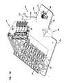
- FIG. 2is perspective view of the fiber optic enclosure of FIG. 1 with a cover in an open position.
- FIG. 3is perspective view of a main body of the fiber optic enclosure of FIG. 1 .
- FIG. 4is a fragmentary perspective view of the main body of FIG. 3 .
- FIG. 5is perspective view of the main body of FIG. 3
- FIG. 6is a fragmentary perspective view of the main body of FIG. 5 .
- FIG. 7is a perspective view of the fiber optic enclosure of FIG. 2 .
- FIG. 8is a perspective view of the fiber optic enclosure of FIG. 2 .
- FIG. 9is perspective view of the main body of the fiber optic enclosure of FIG. 1 .
- FIG. 10is a perspective view of a termination tray suitable for use in the fiber optic enclosure of FIG. 1 .
- FIG. 11is a perspective view of an alternate embodiment of an adapter module suitable for use with the termination tray of FIG. 10 .
- FIG. 12is a perspective view of the adapter module of FIG. 11 .
- FIG. 13is a perspective view of a bend radius protector suitable for use in the fiber optic enclosure of FIG. 1 .
- FIG. 14is a perspective view of the main body of FIG. 9 with the bend radius protector removed.
- FIG. 15is a fragmentary perspective view of the main body of FIG. 14 .
- FIG. 16is a perspective view of a grommet suitable for use with the fiber optic enclosure of FIG. 1 .
- FIG. 17is a perspective view of an alternate embodiment of a grommet suitable for use with the fiber optic enclosure of FIG. 1 .
- FIG. 18is a perspective view of the grommet of FIG. 17 .
- FIG. 19is a perspective view of a cable spool mounting assembly suitable for use with the fiber optic enclosure of FIG. 1 .
- FIG. 20is an exploded perspective view of the cable spool mounting assembly of FIG. 19 .
- FIG. 21is a perspective view of a drum portion of the cable spool mounting assembly of FIG. 19 .
- FIG. 22is a schematic representation of a cable routing scheme.
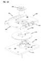
- FIG. 23is an exploded perspective view of an alternate embodiment of a cable spool mounting assembly suitable for use with the fiber optic enclosure of FIG. 1 .
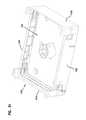
- FIG. 24is a perspective view of a mounting plate suitable for use with the cable spool mounting assembly of FIG. 23 .
- FIG. 25is a perspective view of a cable spool assembly suitable for use with the cable spool mounting assembly of FIG. 23 .
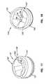
- FIG. 26is a side view of the cable spool assembly of FIG. 25 .
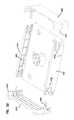
- FIG. 27is an exploded perspective view of the cable spool assembly of FIG. 25 .
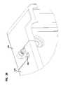
- FIG. 28is a perspective view of an enclosure mount of the cable spool assembly of FIG. 25 .
- FIG. 29is a perspective view of an enclosure mount of the cable spool assembly of FIG. 25 .
- FIG. 30is a perspective view of a strain relief insert suitable for use with the cable spool assembly of FIG. 25 .
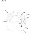
- FIG. 31is an alternate embodiment of a shroud suitable for use with the fiber optic enclosure of FIG. 1 .
- FIG. 32is an exploded perspective view of the shroud of FIG. 31 .
- FIG. 33is a perspective view of an alternate embodiment of a shroud suitable for use with the fiber optic enclosure of FIG. 1 .
- FIG. 34is an exploded perspective view of the shroud of FIG. 33 .
- FIG. 35is a perspective view of the shroud of FIG. 33 .
- FIG. 36is an enlarged fragmentary view of the shroud of FIG. 35 .
- FIG. 37is a perspective view of an adapter suitable for use with the fiber optic enclosure of FIG. 1 .
- FIG. 38is a perspective view of the adapter of FIG. 37 .
- FIG. 39is a perspective view of the adapter of FIG. 37 .
- FIG. 40is a perspective view of a modular fiber optic enclosure.
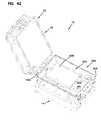
- FIGS. 41-43are perspective views of the modular fiber optic enclosure of FIG. 40 with the main body in an open position.
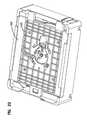
- FIGS. 44-46are perspective views of an alternate embodiment of a main body suitable for use with the fiber optic enclosure of FIG. 1 .
- the fiber optic enclosure 10includes a housing, generally designated 12 , and a cable spool mounting assembly, generally designated 14 .
- the fiber optic enclosure 10provides an enclosure from which lengths of subscriber cable can be dispensed following the mounting of the fiber optic enclosure 10 to a mounting location.
- the subscriber cableis dispensed from the fiber optic enclosure 10 by pulling on an end of the cable.
- the fiber optic enclosure 10rotates about an axis relative to a stationary mounting plate of the fiber optic enclosure. In the event that there is a residual length of subscriber cable that was not dispensed, the fiber optic enclosure can store this residual length.
- the housing 12is molded from a plastic material.
- the housing 12includes a main body, generally designated 16 , having a first sidewall 18 and an oppositely disposed second sidewall 20 .
- the housing 12further includes a cover 22 that is pivotally engaged to the main body 16 .
- the cover 22is pivotally engaged with the main body 16 by a hinge 24 disposed on the first sidewall 18 .
- the hinge 24allows the cover 22 to selectively pivot between a closed position (shown in FIG. 1 ) and an open position (shown in FIG. 2 ).
- a plurality of latches 26is disposed on the second sidewall 20 of the main body 16 .
- the plurality of latches 26is adapted to secure the cover 22 in the closed position.
- Each of the plurality of latches 26includes a latching member 28 that is adapted to receive a portion of an exterior edge portion 30 on the cover 22 and to secure the cover 22 to the main body 16 .
- the main body 16further includes a base wall 58 , a first wall 60 and an opposite second wall 62 .
- the first and second walls 60 and 62extend outwardly from the base wall 58 between the first and second sidewalls 18 , 20 .
- the base wall 58 , the first and second walls 60 and 62 and the first and second sidewalls 18 , 20cooperatively define an interior region 64 .
- the first wall 60includes a punch out 66 .
- the punch out 66defines an area of weakness 68 that allows for the selective removal of the punch out 66 .
- the first wall 60defines a cable opening 70 through which a telecommunications cable can enter the interior region 64 of the main body 16 of the housing 12 .
- the first wall 60further includes a break out 72 that extends from the cable opening 70 through an edge 74 of the first wall 60 . With the break out 72 removed, the cable opening 70 extends through the edge 74 of the main body 16 thereby allowing for a telecommunications cable to be laterally inserted into the interior region 64 rather than having to be inserted axially through the cable opening 70 .
- a channel 76is formed from protrusions 78 from the base wall 58 in the interior region 64 of the main body 16 .
- This channel 76is adapted to hold a retaining wall in place near the cable opening 40 so that a compressible material can be retained adjacent to the cable opening 70 in order to provide a seal about the telecommunications cable entering the interior region 64 .
- a termination tray 80is disposed in the interior region 64 of the main body 16 .
- the termination tray 80includes a first surface 82 and an oppositely disposed second surface 84 .
- the termination tray 80is in engagement with the base wall 58 of the main body 16 .
- the termination tray 80is in snap-fit engagement with the base wall 58 of the main body 16 .
- a plurality of snap-fit latches 85extend outwardly from the second surface 84 of the termination tray 80 and are adapted for engagement with corresponding latches extending outwardly from the base wall 58 of the main body 16 .
- the first surface 82 of the termination tray 80includes a plurality of adapter mounts 86 (best shown in FIG. 10 ).
- the adapter mounts 86are adapted to receive sliding adapter modules 87 in snap-fit engagement. Similar sliding adapter modules have been described in commonly owned U.S. Pat. Nos. 5,497,444; 5,717,810; 6,591,051 and U.S. Pat. Pub. No. 2007/0025675, the disclosures of which are hereby incorporated by reference in their entirety.
- Each of the sliding adapter modules 87defines a plurality of slots 88 .
- each of the sliding adapter modules 87includes 4 slots 88 .
- the plurality of slots 88is adapted to receive a plurality of adapters 89 .
- the plurality of adapters 89is disposed in a linear array in the plurality of sliding adapter modules 87 .
- An opening of each of the slots 88has a width and a height. In the depicted embodiment of FIG. 10 , the width of the opening of the slot 88 is greater than the height of the opening of the slot 88 .
- the sliding adapter module 87 ′includes a plurality of slots 88 ′.
- the sliding adapter module 87 ′includes two slots 88 ′.
- An opening of each of the plurality of slots 88 ′has a width and a height. In the depicted embodiment of FIG. 11 , the height of the opening of the slot 88 ′ is greater than the width of the opening of the slot 88 ′.
- the first surface 82 of the termination tray 80further includes a fan-out mount 90 (best shown in FIG. 12 ).
- the fan-out mount 90is disposed adjacent to the adapter mounts 86 .
- the fan-out mount 90is adapted to receive at least one fan-out 92 on the termination tray 80 in snap-fit engagement.
- the fan-out mount 80is adapted to retain four fan-outs 92 .
- the first surface 92 of the termination tray 80further includes a cable management area 94 .
- the cable management area 94includes a plurality of bend radius protectors 96 and a cable clamp 98 .
- the bend radius protectors 96extend outwardly from the first surface 82 of the termination tray 80 .
- the bend radius protectors 96are integral protrusions from the first surface 82 of the termination tray 80 .
- the bend radius protectors 96include a radius portion 100 and an extension portion 102 .
- the radius portion 100extends outwardly from the first surface 82 in a generally perpendicular direction.
- the extension portion 102is adapted to retain cable around the bend radius protectors 96 .
- the extension portion 102extends outwardly from the radius portion 100 in a direction that is generally parallel with the first surface 82 of the termination tray 80 .
- the cable clamp 98 of the termination tray 80is adapted to retain a cable on the termination tray 80 . This is potentially advantageous as it prevents the connectorized ends of the cable from becoming dislocated from the sliding adapter modules 87 in the event that tension is applied to the cable.
- the termination tray 80is molded from a plastic material.
- the snap-fit latches, the adapter mounts 86 , the fan-out mount 90 and the bend radius protectors 96are integral with the termination tray 80 .
- the snap-fit engagement features of the termination tray 80are potentially advantageous as these features reduce the number of screws required to attach the corresponding components to the termination tray 80 .
- the bend radius protector 110is generally cylindrical in shape and includes a first axial end 112 and an opposite second axial end 114 .
- the bend radius protector 110defines a central opening 116 that extends through the first and second axial ends 112 , 114 .
- the bend radius protector 110further includes an outer surface 118 .
- the outer surface 118defines a groove 120 having a generally concave shape.
- the first axial end 112 of the bend radius protector 110is adapted to engage a cable entry opening 122 (shown in FIGS. 14 and 15 ) in the base wall 58 of the main body 16 .
- the cable entry opening 122is adapted to provide access into the interior region 64 of the main body 16 for cable 123 (shown in FIGS. 14 and 15 ) from the cable spool mounting assembly 14 .
- the central opening 116 of the bend radius protector 110tapers outwardly at the second axial end 114 to prevent any damage to the cable as it passes from the cable entry opening 122 into the interior region 64 .
- a grommet 124is adapted for disposition in the cable entry opening 122 of the base wall 58 .
- the grommet 124is adapted to provide sealing engagement between the cable from the cable spool mounting assembly 14 and the cable entry opening 122 .
- the grommet 124includes an outer circumferential surface 125 and an end surface 126 .
- the outer circumferential surface 125defines a retention groove 127 .
- the retention groove 127is adapted to receive the base wall 58 of the main body 16 surrounding the cable entry opening 122 .
- the grommet 124defines a plurality of thru-holes 128 that extends longitudinally through the grommet 124 and through the end surface 126 .
- a slot 129extends from the outer circumferential surface 125 of the grommet 124 to the thru-hole 128 .
- the slot 129is defined by a first side 130 a and an oppositely disposed second side 130 b .
- the slot 129allows for the cable 123 from the cable spool mounting assembly 14 to be inserted longitudinally into the grommet 124 .
- the first and second sides 130 a , 130 bare pressed together thereby closing the slot 129 .
- the grommet 124 ′includes an outer circumferential surface 125 ′ and an end surface 126 ′.
- the outer circumferential surface 125 ′defines a retention groove 127 ′.
- the retention groove 127 ′is adapted to receive the base wall 58 of the main body 16 surrounding the cable entry opening 122 .
- the grommet 124 ′defines a plurality of thru-holes 128 ′ that extends longitudinally through the grommet 124 ′ and through the end surface 126 ′.
- a slot 129 ′extends from the outer circumferential surface 125 ′ of the grommet 124 ′ to the thru-hole 128 ′.
- the slot 129 ′is defined by a first side 130 a ′ and an oppositely disposed second side 130 b ′.
- the end surface 126 ′ of the grommet 124 ′includes a central portion 131 ′ and an outer edge portion 132 ′.
- the central portion 131 ′is recessed from the outer edge portion 132 ′.
- a portion of the end surface 126 ′ disposed between the central portion 131 ′ and the outer edge portion 132 ′is arcuate in shape.
- the arcuate shape of the portion of the end surface 126 ′ between the central portion 131 ′ and the outer edge portion 132 ′is adapted to prevent any damage to the cable as it passes from the cable entry opening 122 into the interior region 64 .
- the cable spool mounting assembly 14includes a mounting plate 140 , a cable spool assembly 142 and an enclosure mount 144 .
- the mounting plate 140is generally plate shaped and includes a first surface 146 and an opposite second surface 148 .
- the mounting plate 140is adapted for stationary mounting to a mounting location (e.g., a wall, a pole, etc.).
- the first surface 146is adapted to engage the cable spool assembly 142 .
- the first surface 146engages the cable spool assembly 142 so that the cable spool assembly 142 can rotate about a rotating axis 150 .
- the second surface 148is adapted to engage the mounting location.
- a plurality of thru-mounts 152is disposed through the mounting plate 140 . These thru-mounts 152 are adapted to receive fasteners (e.g., screws, bolts, etc.) for engagement with the mounting location.
- the cable spool assembly 142includes an end 154 and a drum portion 158 that is disposed between the end 154 and the enclosure mount 144 .
- the drum portion 158is adapted for coiling or wrapping cable 123 .
- the end 154 of the cable spool assembly 142is adapted for rotational engagement with the mounting plate 140 .
- a bearingis disposed between the end 154 and the mounting plate 140 .
- a bearing suitable for usehas been described in U.S. patent application Ser. No. 12/113,786, the disclosure of which is hereby incorporated by reference in its entirety.
- the end 154includes an end plate 160 and a spindle 162 that extends outwardly from the center of the end plate 160 .
- the end plate 160is generally circular in shape.
- the end plate 160includes a plurality of flats 164 that are oppositely dispose about the circumference of the end plate 160 .
- the end plate 160defines a plurality of notches 166 that extend through the end plate 160 and that are arranged about a first axial end 168 of the spindle 162 . In the subject embodiment, there are four notches 166 equally spaced about the first axial end 168 of the spindle 162 .
- the spindle 162is integral with the end 154 of the cable spool assembly 142 .
- the spindle 162includes the first axial end 168 and an oppositely disposed second axial end 170 .
- the second axial end 170includes a plurality of resilient latches 172 that are adapted for snap-fit engagement with the drum portion 158 .
- the drum portion 158is generally cylindrical in shape and includes an outer surface 174 about which the cable 123 is coiled.
- the drum portion 158further includes a first end portion 176 and an oppositely disposed second end portion 178 .
- the drum portion 158defines a central bore 180 that extends through the drum portion 158 .
- the central bore 180is adapted to receive the spindle 162 of the end 154 .
- the first and second end portions 176 , 178include a plurality of resilient catches 182 .
- the resilient catches 182 of the first end portion 176are adapted for engagement in the notches 166 of the end 154 while the resilient catches 182 of the second end portion 178 are adapted for engagement with notches 184 in the enclosure mount 144 .
- the second end portion 178 of the drum portion 158defines passage 186 .
- the passage 186provides a path from the outer surface 174 to the central bore 180 .
- the passage 186is adapted to provide a path through which an end of the cable 123 that is wrapped around the drum portion 158 can pass for access to the main body 16 .
- Each of a first wall 188 and an oppositely disposed second wall 190 of the passage 186include a radius portion 192 that is adapted to prevent damage to the cable 123 resulting from bending.
- the enclosure mount 144includes a first face 200 and an opposite second face 202 .
- the first face 200is adapted for engagement with the drum portion 158 .
- the second face 202is adapted for engagement with the main body 16 .
- the second face 202includes a strain relief post 204 .
- the strain relief post 204is disposed between the drum portion 158 of the cable spool assembly 142 and the interior region 64 of the housing 12 .
- the strain relief post 204is a generally cylindrical shaped protrusion that extends outwardly from the second face 202 .
- the strain relief post 204is recessed so that the strain relief post 204 does not interfere with the main body 16 when the main body 16 is engaged with the cable spool mounting assembly 14 .
- the strain relief post 204includes an outer surface 206 about which the cable 123 is wrapped. In the subject embodiment, the cable 123 is wrapped about the strain relief post 204 at least once.
- the second face 202further defines a cable guide 208 .
- the cable guide 208is a recessed groove that generally extends from the strain relief post 204 to a location adapted for alignment with the cable entry opening 122 of the base wall 58 .
- the second face 202further defines a retention channel 210 .
- the retention channel 210is adapted to receive the base wall 58 of the main body 16 and retain the base wall 58 in engagement with the enclosure mount 144 .
- the cable spool assembly 142 and the enclosure mount 144are engaged so that the cable spool assembly 142 and the enclosure mount 144 unitarily rotate.
- the cable spool assembly 142is rotationally engaged with the mounting plate 140
- the cable spool assembly 142 and the main body 16selectively rotate in unison about the rotating axis 150 of the mounting plate 140 when the main body 16 is engaged in the enclosure mount 144 .
- the selective rotation of the cable spool assembly 142 and the main body 16 about the rotating axis 150dispenses subscriber cable 123 that is coiled or wrapped about the drum portion 158 of the cable spool assembly 142 .
- This arrangementallows the fiber optic enclosure 10 to be mounted to a mounting location with one end of the subscriber cable 123 in connected engagement with the sliding adapter modules 87 in the interior region 64 of the main body 16 yet still allow for cable 123 to be dispensed from the fiber optic enclosure 10 without disrupting the connection between the fibers of the cable 123 and the adapters 89 .
- the cable 123 in the interior region 64 of the main body 16is protected against over rotation of the cable spool assembly 142 and the main body 16 relative to the mounting plate 140 .
- the mounting plate 140rigidly mounted to a mounting location, if the cable spool assembly 142 and the main body 16 are rotated relative to the mounting plate 140 and the full length of cable 123 is dispensed during the rotation, the tension in the cable 123 will cause the cable spool assembly 142 and the main body 16 to quickly stop. If the strain relief post 204 was not used, this quick stop could result in dislocation of the fibers of the cable 123 from the adapters 89 in the interior region of the main body 16 .
- the use of the strain relief post 204prevents tension from being applied to the cable 123 between the strain relief post 204 and the adapters 89 .
- the cable spool mounting assembly 300includes a mounting plate 302 and a cable spool assembly 304 .
- the mounting plate 302is generally plate shaped and includes a first surface 308 and an oppositely disposed second surface 310 .
- the mounting plate 302is adapted for stationary mounting to a mounting location (e.g., a wall, a pole, etc.).
- the first surface 308is adapted to engage the cable spool assembly 304 while the second surface 310 is adapted to engage the mounting location.
- the first surface 308includes a spindle 312 that extends outwardly from the first surface 308 .
- the spindle 312is centrally disposed on the mounting plate 302 and is adapted to engage the cable spool assembly 304 so that the cable spool assembly 304 can rotate about a rotating axis 314 .
- the spindle 312includes a first axial end 316 and an oppositely disposed second axial end 318 .
- the first axial end 316is engaged to the first surface 308 .
- the first axial end 314is integral with the first surface 308 .
- the first axial end 316 and the first surface 308are monolithic.
- the mounting plate 302defines a plurality of thru-mounts 320 .
- the mounting plate 302defines six thru-mounts 320 .
- the plurality of thru-mounts 320extend through the first and second surfaces 308 , 310 of the mounting plate 302 .
- the plurality of thru-mounts 320is adapted to receive fasteners (e.g., screws, bolts, etc.) for engagement with the mounting location.
- the cable spool assembly 304includes an enclosure mount assembly 322 and a flange 324 .
- the enclosure mount assembly 322includes an enclosure mount 326 and a strain relief post 328 .
- the enclosure mount 326includes a first face 330 and an opposite second face 332 .
- the first face 330includes a drum portion 334 that is centrally disposed on the first face 330 .
- the drum portion 334 and the first face 330are integral.
- the drum portion 334extends outwardly from the first face 330 in a direction that is generally perpendicular to the first face 330 .
- the drum portion 334includes an outer circumference 336 , about which the cable 123 is coiled or wrapped.
- the drum portion 334further includes a first end portion 338 , which is in connected engagement with the first face 330 of the enclosure mount 326 , and an oppositely disposed second end portion 340 .
- the drum portion 334defines a central longitudinal bore 342 , which extends longitudinally through the center of the drum portion 334 .
- the central longitudinal bore 342extends through the first and second end portions 338 , 340 of the drum portion 334 and the first and second faces 330 , 332 .
- the central longitudinal bore 342defines an opening 344 at the second end portion 340 of the drum portion 334 .
- the central longitudinal bore 342is adapted to receive the spindle 312 of the mounting plate 302 through the opening 344 in the second end portion 340 .
- an inner diameter of the central longitudinal bore 342is slightly larger than an outer diameter of the spindle 312 so that the enclosure mount 326 can rotate about the rotating axis 314 .
- the second face 332is adapted for engagement with the main body 16 .
- the second face 332defines a central recess 350 .
- the central recess 350is adapted to receive a strain relief insert 352 .
- the second face 332further defines a cable guide 354 .
- the cable guide 354provides a cable pathway to the main body 16 of the housing 12 .
- the cable guide 354is adapted to route cable from the strain relief insert 352 to the central entry opening 122 of the main body 16 .
- the cable guide 354is a recessed groove that generally extends from the central recess 350 to an outer periphery portion 356 of the enclosure mount 326 . In the depicted embodiment of FIGS. 25 , 27 and 28 , the cable guide 354 extends through a side wall 358 of the enclosure mount 326 . The cable guide 354 is positioned so that a portion of the cable guide 354 is aligned with the cable entry opening 122 of the main body 16 .
- the enclosure mount 326includes a plurality of retention tabs 360 that extends outwardly from sidewalls 362 of the cable guide 354 .
- the retention tabs 360are adapted to retain the cable 123 in the cable guide 354 .
- the enclosure mount 326includes a first side projection 364 a and an oppositely disposed second side projection 364 b .
- the first and second side projections 364 a , 364 bextend outwardly from the second face 332 .
- the first and second side projections 364 a , 364 bextend outwardly from the second face 332 in a direction that is generally perpendicular to the second face 332 .
- the first side projection 364 aincludes a first retention edge 366 a that extends outwardly from the first side projection 364 a .
- the second side projection 364 bincludes a second retention edge 366 b that extends outwardly from the second side projection 364 b.
- the second face 332 , the first side projection 364 a and the first retention edge 366 acooperatively define a first retention channel 368 while the second face 332 , the second side projection 364 b and the second retention edge 366 b cooperatively define a second retention channel.
- the first and second retention channels 368are adapted to receive the base wall 58 of the main body 16 and retain the base wall 58 of the main body 16 in engagement with the enclosure mount 326 .
- Each of the first and second retention channels 368includes a first end 370 a and an oppositely disposed second end 370 b.
- the second face 332further includes a plurality of resilient latches 372 .
- Each of the resilient latches 372includes a free end portion 374 that extends outwardly from the second face 332 .
- the free end portions 374 of the resilient latches 372are adapted to engage the base wall 58 of the main body 16 .
- outer periphery portions of the base wall 58are inserted into the first ends 370 a of the first and second retention channels 366 a , 366 b .
- the main body 16is then pushed toward the enclosure mount 326 so that the outer periphery portions of the main body 16 are disposed in the first and second retention channels 368 .
- the resilient latches 372engage the base wall 58 of the main body 16 .
- the enclosure mount 326defines a cable opening 375 that extends through the first and second faces 330 , 332 .
- the cable opening 375is offset from the drum portion 334 .
- the cable opening 375is adapted to provide a path through which the cable 123 can pass from the drum portion 334 through the enclosure mount 326 to the second face 332 of the enclosure mount 332 .
- the strain relief insert 352is shown.
- the strain relief insert 352is adapted for engagement with the enclosure mount 326 .
- the strain relief insert 352is disposed in the cable recess 350 so that the strain relief insert 352 does not interfere with the main body 16 when the main body 16 is engaged with the cable spool mounting assembly 300 .
- the strain relief insert 352includes a first surface 376 and an oppositely disposed second surface 378 .
- the first surface 376 of the strain relief insert 352includes the strain relief post 328 .
- the strain relief post 328is a generally cylindrical shaped protrusion that extends outwardly from the first surface 376 of the strain relief insert 352 .
- the strain relief post 328includes an outer surface 380 about which the cable 123 is wrapped. In the subject embodiment, the cable 123 is wrapped about the strain relief post 328 at least once.
- the strain relief post 328further includes a plurality of retention projections 382 that extends outwardly from the outer surface 380 at an end 384 of the strain relief post 378 .
- the first surface 376 of the strain relief insert 352includes a cable path 385 .
- the cable path 385is adapted to route the cable 123 from the cable opening 375 defined by the enclosure mount 326 , around the strain relief post 328 and to the cable guide 354 .
- the cable path 385is defined by a cable guide wall 386 that extends outwardly from the first surface 376 of the strain relief insert 352 .
- the cable guide wall 386includes a plurality of bend radius protectors 387 at a cable entrance location, which is disposed adjacent to the cable opening 375 in the enclosure mount 326 , to the cable path 385 .
- the second surface 378 of the strain relief insert 352includes a plurality of resilient latches 388 that extend outwardly from the second surface 378 .
- Each of the resilient latches 388extends in a direction that is generally perpendicular to the second surface 378 .
- the resilient latches 388are adapted for engagement with the drum portion 334 of the enclosure mount 326 .
- the resilient latches 388are adapted for snap-fit engagement with the enclosure mount 326 .
- the flange 324is generally circular in shape and includes a first surface 390 and an oppositely disposed second surface 392 .
- the first surface 390includes a plurality of latches 394 that extend outwardly from the first surface 390 .
- the first surface 390includes four latches 394 .
- the plurality of latches 394extend outwardly from the first surface 390 in a direction that is generally perpendicular to the first surface 390 .
- the plurality of latches 394is adapted to engage the drum portion 334 of the enclosure mount 326 so that the flange 324 is disposed at the second end portion 340 of the drum portion 334 .
- the flange 324defines an opening 396 that extends through the first and second surfaces 390 , 392 of the flange 324 .
- the flange 324further defines a slot 398 that extends from an outer edge 399 of the flange 324 to the opening 396 .
- the shroud 400is adapted to retain the position of the cable spool assembly 142 , 304 relative to the housing 12 .
- the shroud 400includes a first member 402 and a second member 404 .
- the first and second members 402 , 404 of the shroud 400are adapted to engage the sides of the mounting plate 140 , 302 and to engage the main body 16 of the housing 12 .
- the first member 402includes a plurality of resilient latches 406 while the second member 404 includes a plurality of notches 408 .
- the resilient latches 406are adapted for snap-fit engagement with the plurality of notches 408 .
- Each of the first and second members 402 , 404 of the shroud 400defines a channel 410 that is adapted to receive an outer edge of the mounting plate 140 .
- the first and second members 402 , 404 of the shroud 400have a height that is greater than the height of the drum portion 158 of the cable spool assembly 142 so that the main body 16 can be prevented from rotating relative to the mounting plate 140 when the shroud 400 is engaged.
- the shroud 420include a first side member 422 , an opposite second side member 424 , a third side member 426 and an opposite fourth side member 428 .
- the first and second side members 422 , 424are adapted to engage the longitudinal sides of the mounting plate 140 and the main body 16 while the third and fourth side members 426 , 428 are adapted to engage the sides of the mounting plate 140 and the main body 16 that are adjacent to the longitudinal sides.
- first and second side members 422 , 424are adapted for snap-fit engagement with the third and fourth side members 426 , 428 .
- the third and fourth side members 426 , 428include latches 430 that are adapted to engage notches 432 defined by the first and second side members 422 , 424 .
- the third and fourth side members 426 , 428further include corner projections 434 .
- the corner projections 434are adapted to engage a portion of the corners of the enclosure mount 326 .
- the shroud 440includes a first side member 442 and an oppositely disposed second side member 444 .
- the first and second side members 442 , 444are generally U-shaped.
- Each of the first and second side members 442 , 444includes a main wall 446 , a first wall 448 and a second wall 450 .
- the main wall 446includes a first end 452 and an oppositely disposed second end 454 .
- the first wall 448extends outwardly from the main wall 446 at the first end 452 while the second wall 450 extends outwardly from the main wall 446 at the second end 454 .
- the first wall 448is longer than the second wall 450 .
- Each of the first walls 448 of the first and second side members 442 , 444includes a resilient latch 456 .
- the resilient latch 456 of the first wall 448 of the first side member 442is adapted for engagement with a notch 458 defined by the second wall 450 of the second side member 444 while the resilient latch 456 of the first wall 448 of the second side member 444 is adapted for engagement with the notch 458 defined by the second wall 450 of the first side member 442 .
- the first wall 448defines a release groove 460 that is adjacent to the resilient latch 456 .
- the release groove 460provides a location at which a tool can be inserted to separate the first and second side members 442 , 444 .
- the cable adapter 470is configured for snap-fit engagement with the shroud 400 .
- the cable adapter 470is generally cylindrical in shape and includes a first axial end portion 472 and an opposite second axial end portion 474 .
- the cable adapter 470defines a bore 476 that extends through the first and second axial end portions 472 , 474 .
- the first axial end portion 472includes a plurality of resilient latches 478 that extend outwardly from the first axial end portion 472 in an axial direction.
- the resilient latches 478are adapted for engagement with notches 480 (shown in FIG. 32 ) disposed in the shroud 400 , 420 , 440 and/or the main body 16 .
- the second axial end portion 474includes a plurality of resilient latches 482 .
- Each of the resilient latches 482includes a free end 484 that extends inwardly into the bore 476 of the cable adapter 470 .
- the resilient latches 482are adapted to engage cable conduit.
- the fiber optic enclosure 10is shown with a splice module 500 .
- the fiber optic enclosure 10is modular.
- the main body 16can be removed from the enclosure mount 114 and engaged with the splice module 500 .
- the main body 16is pivotally engaged with the splice module 500 by a hinge 502 .
- the hinge 502allows the main body 16 to selectively pivot relative to the splice module 500 between a closed position (shown in FIG. 40 ) and an open position (shown in FIGS. 41-43 ).
- a plurality of latches 504is adapted to secure the main body 16 in the closed position relative to the splice module.
- the splice module 500defines an interior 506 .
- a splice tray 508is disposed in the interior 506 of the splice module 500 .
- the splice tray 508is engaged with a splice tray holder 510 .
- the splice tray 508is in snap-fit engagement with the splice tray holder 510 .
- the splice tray holder 510is in snap-fit engagement with the splice module 500 .
- the housing 612includes a main body 616 and a cover 622 pivotally engaged with the main body 616 .
- the main body 616 and the cover 622cooperatively define an interior region 664 .
- a bulkhead 670is disposed in the interior region 664 .
- the bulkhead 670is mounted to a termination tray 680 .
- the termination tray 680is in engagement with the main body 616 .
- the bulkhead 670includes a plurality of adapters 682 mounted to the bulkhead 670 .
- the adapters 682include a first end 684 and an opposite second end 686 . Each of the first and second ends 684 , 686 is adapted to receive a connectorized end of a fiber optic cable.
Landscapes
- Physics & Mathematics (AREA)
- General Physics & Mathematics (AREA)
- Optics & Photonics (AREA)
- Light Guides In General And Applications Therefor (AREA)
- Storage Of Web-Like Or Filamentary Materials (AREA)
Abstract
Description
Claims (21)
Priority Applications (1)
| Application Number | Priority Date | Filing Date | Title |
|---|---|---|---|
| US12/560,181US8265447B2 (en) | 2008-09-16 | 2009-09-15 | Modular fiber optic enclosure with external cable spool |
Applications Claiming Priority (2)
| Application Number | Priority Date | Filing Date | Title |
|---|---|---|---|
| US9753608P | 2008-09-16 | 2008-09-16 | |
| US12/560,181US8265447B2 (en) | 2008-09-16 | 2009-09-15 | Modular fiber optic enclosure with external cable spool |
Publications (2)
| Publication Number | Publication Date |
|---|---|
| US20100074587A1 US20100074587A1 (en) | 2010-03-25 |
| US8265447B2true US8265447B2 (en) | 2012-09-11 |
Family
ID=42037774
Family Applications (1)
| Application Number | Title | Priority Date | Filing Date |
|---|---|---|---|
| US12/560,181Expired - Fee RelatedUS8265447B2 (en) | 2008-09-16 | 2009-09-15 | Modular fiber optic enclosure with external cable spool |
Country Status (5)
| Country | Link |
|---|---|
| US (1) | US8265447B2 (en) |
| AU (1) | AU2009293407A1 (en) |
| CA (1) | CA2737530A1 (en) |
| MX (1) | MX2011002822A (en) |
| WO (1) | WO2010033535A2 (en) |
Cited By (31)
| Publication number | Priority date | Publication date | Assignee | Title |
|---|---|---|---|---|
| US20110222829A1 (en)* | 2010-03-11 | 2011-09-15 | Todd Loeffelholz | Fiber optic enclosure with internal cable spool assembly |
| US20120063735A1 (en)* | 2008-12-31 | 2012-03-15 | Opterna Am, Inc. | Fiber Distribution Terminals |
| US20120093473A1 (en)* | 2010-10-19 | 2012-04-19 | Terry Dean Cox | Transition box for multiple dwelling unit fiber optic distribution network |
| US8494334B2 (en)* | 2007-09-05 | 2013-07-23 | Adc Telecommunications, Inc. | Fiber optic enclosure with tear-away spool |
| US20130209052A1 (en)* | 2012-02-13 | 2013-08-15 | Opterna Am, Inc. | Adapter Retaining Systems |
| US8792767B2 (en) | 2010-04-16 | 2014-07-29 | Ccs Technology, Inc. | Distribution device |
| US8798427B2 (en) | 2007-09-05 | 2014-08-05 | Corning Cable Systems Llc | Fiber optic terminal assembly |
| US8879882B2 (en) | 2008-10-27 | 2014-11-04 | Corning Cable Systems Llc | Variably configurable and modular local convergence point |
| US8909019B2 (en) | 2012-10-11 | 2014-12-09 | Ccs Technology, Inc. | System comprising a plurality of distribution devices and distribution device |
| US20150093088A1 (en)* | 2013-09-30 | 2015-04-02 | Optema Technology Limited | Fiber Optic Terminal Assemblies |
| US9004778B2 (en) | 2012-06-29 | 2015-04-14 | Corning Cable Systems Llc | Indexable optical fiber connectors and optical fiber connector arrays |
| US9049500B2 (en) | 2012-08-31 | 2015-06-02 | Corning Cable Systems Llc | Fiber optic terminals, systems, and methods for network service management |
| US9057860B2 (en) | 2007-05-07 | 2015-06-16 | Adc Telecommunications, Inc. | Fiber optic enclosure with external cable spool |
| US9078287B2 (en) | 2010-04-14 | 2015-07-07 | Adc Telecommunications, Inc. | Fiber to the antenna |
| US9188760B2 (en) | 2011-12-22 | 2015-11-17 | Adc Telecommunications, Inc. | Mini rapid delivery spool |
| US9219546B2 (en) | 2011-12-12 | 2015-12-22 | Corning Optical Communications LLC | Extremely high frequency (EHF) distributed antenna systems, and related components and methods |
| US9223106B2 (en) | 2011-06-24 | 2015-12-29 | Commscope Technologies Llc | Fiber termination enclosure with modular plate assemblies |
| US9261663B2 (en) | 2010-06-18 | 2016-02-16 | Adc Communications (Shanghai) Co., Ltd. | Fiber optic distribution terminal and method of deploying fiber distribution cable |
| US9323020B2 (en) | 2008-10-09 | 2016-04-26 | Corning Cable Systems (Shanghai) Co. Ltd | Fiber optic terminal having adapter panel supporting both input and output fibers from an optical splitter |
| US9494757B2 (en)* | 2012-02-29 | 2016-11-15 | Commscope Technologies Llc | Fiber optic cable packaging arrangement |
| US9547144B2 (en) | 2010-03-16 | 2017-01-17 | Corning Optical Communications LLC | Fiber optic distribution network for multiple dwelling units |
| US9594217B2 (en) | 2012-08-07 | 2017-03-14 | Adc Telecommunications (Shanghai) Distribution Co., Ltd. | Fiber optic splicing assembly |
| US9664871B1 (en)* | 2015-11-19 | 2017-05-30 | Corning Optical Communications LLC | Fiber optic drawer tray having rotatable spool for deployment of fiber optic cable, and related components, systems, and methods |
| US9684142B2 (en) | 2012-11-07 | 2017-06-20 | CommScope Connectivity Belgium BVBA | Rapid distribution terminal |
| US9703063B2 (en) | 2012-11-07 | 2017-07-11 | CommScope Connectivity Belgium BVBA | Cable over-length storage system |
| US20170199344A1 (en)* | 2007-08-06 | 2017-07-13 | Commscope Technologies Llc | Fiber optic enclosure with internal cable spool |
| US9835814B2 (en) | 2013-11-06 | 2017-12-05 | Adc Czech Republic S.R.O. | Fiber termination point with overlength storage |
| US10110307B2 (en) | 2012-03-02 | 2018-10-23 | Corning Optical Communications LLC | Optical network units (ONUs) for high bandwidth connectivity, and related components and methods |
| US10330880B2 (en) | 2015-07-23 | 2019-06-25 | Commscope Technologies Llc | Cable spool re-orientation device for a wall box |
| US10788641B2 (en) | 2016-02-12 | 2020-09-29 | Ppc Broadband, Inc. | Cable spool and storage |
| US20240159984A1 (en)* | 2022-11-14 | 2024-05-16 | Jiangsu SUMEC Electromechanical Co., Ltd. | Optical cable assembly and optical cable testing method |
Families Citing this family (42)
| Publication number | Priority date | Publication date | Assignee | Title |
|---|---|---|---|---|
| US8452148B2 (en) | 2008-08-29 | 2013-05-28 | Corning Cable Systems Llc | Independently translatable modules and fiber optic equipment trays in fiber optic equipment |
| US8184938B2 (en) | 2008-08-29 | 2012-05-22 | Corning Cable Systems Llc | Rear-installable fiber optic modules and equipment |
| US11294136B2 (en) | 2008-08-29 | 2022-04-05 | Corning Optical Communications LLC | High density and bandwidth fiber optic apparatuses and related equipment and methods |
| EP2221932B1 (en) | 2009-02-24 | 2011-11-16 | CCS Technology Inc. | Holding device for a cable or an assembly for use with a cable |
| US8699838B2 (en) | 2009-05-14 | 2014-04-15 | Ccs Technology, Inc. | Fiber optic furcation module |
| US8538226B2 (en) | 2009-05-21 | 2013-09-17 | Corning Cable Systems Llc | Fiber optic equipment guides and rails configured with stopping position(s), and related equipment and methods |
| US9075216B2 (en) | 2009-05-21 | 2015-07-07 | Corning Cable Systems Llc | Fiber optic housings configured to accommodate fiber optic modules/cassettes and fiber optic panels, and related components and methods |
| US8712206B2 (en) | 2009-06-19 | 2014-04-29 | Corning Cable Systems Llc | High-density fiber optic modules and module housings and related equipment |
| WO2010148325A1 (en) | 2009-06-19 | 2010-12-23 | Corning Cable Systems Llc | High fiber optic cable packing density apparatus |
| EP2443497B1 (en) | 2009-06-19 | 2020-03-04 | Corning Cable Systems LLC | High density and bandwidth fiber optic apparatus |
| US8428419B2 (en)* | 2009-09-23 | 2013-04-23 | Adc Telecommunications, Inc. | Fiber distribution hub with internal cable spool |
| US8625950B2 (en) | 2009-12-18 | 2014-01-07 | Corning Cable Systems Llc | Rotary locking apparatus for fiber optic equipment trays and related methods |
| US8992099B2 (en) | 2010-02-04 | 2015-03-31 | Corning Cable Systems Llc | Optical interface cards, assemblies, and related methods, suited for installation and use in antenna system equipment |
| US8913866B2 (en) | 2010-03-26 | 2014-12-16 | Corning Cable Systems Llc | Movable adapter panel |
| CA2796221C (en) | 2010-04-16 | 2018-02-13 | Ccs Technology, Inc. | Sealing and strain relief device for data cables |
| EP2381284B1 (en) | 2010-04-23 | 2014-12-31 | CCS Technology Inc. | Under floor fiber optic distribution device |
| US9075217B2 (en) | 2010-04-30 | 2015-07-07 | Corning Cable Systems Llc | Apparatuses and related components and methods for expanding capacity of fiber optic housings |
| US9519118B2 (en) | 2010-04-30 | 2016-12-13 | Corning Optical Communications LLC | Removable fiber management sections for fiber optic housings, and related components and methods |
| US8660397B2 (en) | 2010-04-30 | 2014-02-25 | Corning Cable Systems Llc | Multi-layer module |
| US8705926B2 (en) | 2010-04-30 | 2014-04-22 | Corning Optical Communications LLC | Fiber optic housings having a removable top, and related components and methods |
| US9632270B2 (en) | 2010-04-30 | 2017-04-25 | Corning Optical Communications LLC | Fiber optic housings configured for tool-less assembly, and related components and methods |
| US9720195B2 (en) | 2010-04-30 | 2017-08-01 | Corning Optical Communications LLC | Apparatuses and related components and methods for attachment and release of fiber optic housings to and from an equipment rack |
| US8879881B2 (en) | 2010-04-30 | 2014-11-04 | Corning Cable Systems Llc | Rotatable routing guide and assembly |
| CN110174737A (en) | 2010-06-23 | 2019-08-27 | Adc电信公司 | Telecommunication assembly |
| US8718436B2 (en) | 2010-08-30 | 2014-05-06 | Corning Cable Systems Llc | Methods, apparatuses for providing secure fiber optic connections |
| US9279951B2 (en) | 2010-10-27 | 2016-03-08 | Corning Cable Systems Llc | Fiber optic module for limited space applications having a partially sealed module sub-assembly |
| US8662760B2 (en) | 2010-10-29 | 2014-03-04 | Corning Cable Systems Llc | Fiber optic connector employing optical fiber guide member |
| US9116324B2 (en) | 2010-10-29 | 2015-08-25 | Corning Cable Systems Llc | Stacked fiber optic modules and fiber optic equipment configured to support stacked fiber optic modules |
| CA2819235C (en) | 2010-11-30 | 2018-01-16 | Corning Cable Systems Llc | Fiber device holder and strain relief device |
| US8622481B2 (en) | 2011-01-25 | 2014-01-07 | Joy Mm Delaware, Inc. | Fiber optic cable protection in a mining system |
| WO2012106510A2 (en) | 2011-02-02 | 2012-08-09 | Corning Cable Systems Llc | Dense fiber optic connector assemblies and related connectors and cables suitable for establishing optical connections for optical backplanes in equipment racks |
| US9008485B2 (en) | 2011-05-09 | 2015-04-14 | Corning Cable Systems Llc | Attachment mechanisms employed to attach a rear housing section to a fiber optic housing, and related assemblies and methods |
| AU2012275598A1 (en) | 2011-06-30 | 2014-01-16 | Corning Optical Communications LLC | Fiber optic equipment assemblies employing non-U-width-sized housings and related methods |
| AU2011205016A1 (en)* | 2011-07-27 | 2013-02-14 | Tyco Electronics Services Gmbh | Surface-mountable enclosure |
| US8953924B2 (en) | 2011-09-02 | 2015-02-10 | Corning Cable Systems Llc | Removable strain relief brackets for securing fiber optic cables and/or optical fibers to fiber optic equipment, and related assemblies and methods |
| US9038832B2 (en) | 2011-11-30 | 2015-05-26 | Corning Cable Systems Llc | Adapter panel support assembly |
| US9250409B2 (en) | 2012-07-02 | 2016-02-02 | Corning Cable Systems Llc | Fiber-optic-module trays and drawers for fiber-optic equipment |
| ES2551077T3 (en) | 2012-10-26 | 2015-11-16 | Ccs Technology, Inc. | Fiber optic management unit and fiber optic distribution device |
| ES1141660Y (en) | 2012-12-19 | 2015-10-14 | Tyco Electronics Raychem Bvba | Distribution device with incrementally added dividers |
| US8985862B2 (en) | 2013-02-28 | 2015-03-24 | Corning Cable Systems Llc | High-density multi-fiber adapter housings |
| CN206147157U (en)* | 2016-11-15 | 2017-05-03 | 浙江超前通信设备有限公司 | Optical Splice Closure |
| EP4305482A4 (en)* | 2021-03-12 | 2025-01-22 | CommScope Technologies LLC | FIBER OPTIC ADMINISTRATION FILE |
Citations (125)
| Publication number | Priority date | Publication date | Assignee | Title |
|---|---|---|---|---|
| US1276825A (en) | 1916-07-21 | 1918-08-27 | David Swope | Automatic take-up attachment for portable-telephone conductors. |
| US1442999A (en) | 1921-03-03 | 1923-01-23 | Boyle Rudolph Boardman | Automatic reel for electric devices |
| US1446410A (en) | 1922-03-31 | 1923-02-20 | Bennett Sandy Boyd | Winding reel |
| US1474580A (en) | 1923-02-19 | 1923-11-20 | George L Clark | Electric-wiring machine |
| USRE20995E (en) | 1939-02-07 | beasley | ||
| US2434363A (en) | 1946-04-27 | 1948-01-13 | Frank J Lenox | Spool |
| US2502496A (en) | 1944-09-30 | 1950-04-04 | George D Wickman | Equalizer for ground conductors |
| US2521226A (en) | 1946-09-07 | 1950-09-05 | Hugo F Keller | Electric cord reel |
| US2727703A (en) | 1952-11-15 | 1955-12-20 | Robert N Bonnett | Insert for coreless roll of wire |
| US3091433A (en) | 1961-10-02 | 1963-05-28 | Black & Decker Mfg Co | Vacuum-actuated apparatus and method for drawing lines through a pipe or conduit |
| US3131729A (en) | 1959-12-04 | 1964-05-05 | Sulzer Ag | Weft thread supply system for looms for weaving |
| US3657491A (en) | 1970-05-28 | 1972-04-18 | Illinois Tool Works | Cord reel |
| US3667417A (en) | 1970-04-24 | 1972-06-06 | Us Navy | Messenger buoy recovery device |
| US3920308A (en) | 1974-04-01 | 1975-11-18 | Harry C Murray | Ready stored power cord |
| US3940086A (en) | 1973-11-23 | 1976-02-24 | Stoquelet Michel R A | Reel for a cable |
| US4053118A (en) | 1976-05-21 | 1977-10-11 | Swing-Shift Mfg. Co. | Reversible reel unit |
| US4081258A (en) | 1976-05-12 | 1978-03-28 | International Telephone And Telegraph Corporation | Method for using on line optic fiber loss monitor |
| US4282954A (en) | 1980-02-11 | 1981-08-11 | Hill John O | Rewinder device |
| US4384688A (en) | 1981-05-26 | 1983-05-24 | Warren F. B. Lindsley | Self-storing cord and hose reel assemblies |
| FR2566997A1 (en) | 1984-07-03 | 1986-01-10 | Reden Karl | Fishing line reel with external spool |
| US4587801A (en) | 1984-05-30 | 1986-05-13 | Societe Anonyme De Telecommunications | System for rotationally slaving an optical fiber feeding and dispensing device in a cabling line |
| US4635875A (en) | 1984-01-19 | 1987-01-13 | Apple Merrill K | Cable pulling device |
| US4657140A (en) | 1985-12-18 | 1987-04-14 | The United States Of America As Represented By The Secretary Of The Air Force | Fiber optic cable storage device |
| US4666237A (en) | 1983-01-27 | 1987-05-19 | British Telecommunications Public Limited Company | Optical fibre terminations and methods of and apparatus for making optical fibre terminations |
| US4669705A (en) | 1984-09-07 | 1987-06-02 | Langston Ralph C | Apparatus for pulling long runs of fiber optic cable |
| US4767073A (en) | 1984-09-10 | 1988-08-30 | Malzacher Fred H | Cable spooling system |
| US4846343A (en) | 1988-04-11 | 1989-07-11 | Amp Incorporated | Packaging for coiled fiber optic cable assemblies |
| US4869437A (en) | 1987-07-16 | 1989-09-26 | Sms Schloemann-Siemag Aktiengesellschaft | Wire coiling apparatus with a recovery device for a coiled wire reel |
| US4880182A (en) | 1988-03-25 | 1989-11-14 | Stanley Gelfman | Cable reel |
| US4883337A (en) | 1988-08-29 | 1989-11-28 | The Charles Stark Draper Laboratory, Inc. | Low strain optical fiber coil |
| US4913369A (en) | 1989-06-02 | 1990-04-03 | Welch Allyn, Inc. | Reel for borescope insertion tube |
| US4938432A (en) | 1989-04-12 | 1990-07-03 | Cooper Industries, Inc. | Cable spool with integral end storage flange |
| US4940859A (en) | 1989-07-24 | 1990-07-10 | Daniel Peterson | Telephone cord take-up reel assembly |
| US4939798A (en) | 1988-10-17 | 1990-07-10 | Last Harry J | Leading edge and track slider system for an automatic swimming pool cover |
| US5013121A (en) | 1989-06-29 | 1991-05-07 | Anton Mark A | Optical fiber storage container |
| US5016554A (en) | 1990-03-29 | 1991-05-21 | Romar Technologies, Inc. | Line storage reel for boat fenders, respectively, boat fenders equipped with line storage reels |
| US5066256A (en) | 1989-02-17 | 1991-11-19 | Ward Sr Robert B | Buoy and releasing system for ships in distress |
| US5074863A (en) | 1990-10-12 | 1991-12-24 | Dines Lenna V | Disposable retractable surgical instrument |
| US5109467A (en) | 1991-02-27 | 1992-04-28 | Keptel, Inc. | Interconnect cabinet for optical fibers |
| JPH04323605A (en)* | 1991-04-23 | 1992-11-12 | Sumitomo Electric Ind Ltd | light rotary drum |
| US5169969A (en) | 1990-06-07 | 1992-12-08 | Akzo Nv | Process for forming mixed bimetal alkoxide-carboxylate composition and novel compositions thereof |
| US5185843A (en) | 1992-01-28 | 1993-02-09 | At&T Bell Laboratories | Restoration kit for communications cable |
| US5265815A (en) | 1992-06-17 | 1993-11-30 | The United States Of America As Represented By The Secretary Of The Army | Multi-cable storage and retrieval device |
| US5280861A (en) | 1992-11-25 | 1994-01-25 | Lippert Pintlepin Mfg. Inc. | Spool assembly for pintle |
| DE4226368A1 (en) | 1992-08-09 | 1994-02-10 | Suhner Elektronik Gmbh | Transmission path for systems equipped with fiber optic cables |
| US5323479A (en) | 1993-06-17 | 1994-06-21 | Porta Systems Corp. | Package for fiber optic cable |
| US5335874A (en) | 1992-11-20 | 1994-08-09 | Siecor Corporation | Connectorized optical fiber cable reel |
| US5388781A (en) | 1991-01-30 | 1995-02-14 | Sauber; Charles J. | Cable pulling and reeling apparatus having anti-spill device and method |
| US5394466A (en) | 1993-02-16 | 1995-02-28 | Keptel, Inc. | Combination telephone network interface and cable television apparatus and cable television module |
| US5494446A (en) | 1994-01-05 | 1996-02-27 | Delucia; Eugene | Receptacle mounted, retractable, extension cord |
| US5519275A (en) | 1994-03-18 | 1996-05-21 | Coleman Powermate, Inc. | Electric machine with a transformer having a rotating component |
| US5520346A (en) | 1992-12-10 | 1996-05-28 | The United States Of America As Represented By The Secretary Of The Navy | Reel payout system |
| US5522561A (en) | 1992-06-03 | 1996-06-04 | The United States Of America As Represented By The Secretary Of The Navy | Fiber optic cable payout system |
| US5529186A (en) | 1994-12-09 | 1996-06-25 | At&T Corp. | Boxed pay-out reel for optic fiber cable or wire or the like, with smooth pay-out, high-impact and cable end holding features |
| US5544836A (en) | 1994-06-03 | 1996-08-13 | Lloyds International Trust | Extensible and self-retractable cable device |
| US5551545A (en) | 1994-03-18 | 1996-09-03 | Gelfman; Stanley | Automatic deployment and retrieval tethering system |
| JPH0968616A (en)* | 1995-09-01 | 1997-03-11 | Fujitsu Ltd | Optical fiber storage device |
| US5638481A (en) | 1995-09-26 | 1997-06-10 | Lucent Technologies Inc. | Flush mounted outlet |
| US5703990A (en) | 1996-03-14 | 1997-12-30 | Lucent Technologies Inc. | Apparatus for housing a linearized optical fiber amplifier |
| US5709347A (en) | 1995-07-24 | 1998-01-20 | Alcatel Kabel Ag & Co | Device for electromagnetically braking and clutching a spool |
| US5717810A (en) | 1994-01-21 | 1998-02-10 | Adc Telecommunications, Inc. | High-density fiber distribution frame |
| US5718397A (en) | 1996-12-23 | 1998-02-17 | Sonoco Products Company, Inc. | Reel having concentric flange supports |
| US5749148A (en) | 1993-12-22 | 1998-05-12 | The Toro Company | Filament trimmer head |
| US5773757A (en) | 1996-08-12 | 1998-06-30 | Pembroke Properties, Inc. | Retractable electrical power cord apparatus |
| US5787219A (en) | 1996-03-20 | 1998-07-28 | Siemens Aktiengesellschaft | Cable closure |
| US5915062A (en) | 1997-07-01 | 1999-06-22 | Lucent Technologies Inc. | Low loss optical fiber reel |
| US5915640A (en) | 1996-02-14 | 1999-06-29 | Innoessentials International B.V. | Reel for storing surplus cable |
| US5987203A (en) | 1997-10-09 | 1999-11-16 | Lucent Technologies Inc. | Distribution module for optical couplings |
| US5992787A (en) | 1997-02-06 | 1999-11-30 | Burke; Donald D. | Cord reel and storage device |
| US6087587A (en) | 1998-05-08 | 2000-07-11 | Gonzalez; Sean | Electrical outlet box with extendable connector |
| US6215938B1 (en) | 1998-09-21 | 2001-04-10 | Adc Telecommunications, Inc. | Fiber optic cabinet and tray |
| US6220413B1 (en) | 1999-10-19 | 2001-04-24 | Siecor Operations, Llc | Retractable cable reel |
| EP1107031A1 (en) | 1999-12-07 | 2001-06-13 | Molex Incorporated | Alignment system for mating connectors |
| US6315598B1 (en) | 2000-02-01 | 2001-11-13 | Adc Telecommunications, Inc. | Outlet box with cable management spool |
| US20010048044A1 (en) | 2000-05-30 | 2001-12-06 | Sumitomo Wiring Systems, Ltd. | Cable reel structure |
| US20020023814A1 (en) | 2000-02-29 | 2002-02-28 | Andrew Poutiatine | Daul retractable cord device with sliding electrical connector |
| US6361360B1 (en)* | 2000-09-26 | 2002-03-26 | Agilent Technologies, Inc. | Expandable strain relief for flexible cable-like members |
| US6385381B1 (en) | 1999-09-21 | 2002-05-07 | Lucent Technologies Inc. | Fiber optic interconnection combination closure |
| US20020164121A1 (en) | 2001-03-15 | 2002-11-07 | 3M Innovative Properties Company | Wide-bandwidth chirped fiber bragg gratings with low delay ripple amplitude |
| US20020171002A1 (en) | 2001-05-21 | 2002-11-21 | Lake Restoration, Inc. | Retractable fence having a line dispenser |
| US6496641B1 (en) | 1999-08-12 | 2002-12-17 | Bellsouth Intellectual Property Corporation | Fiber optic interface device |
| US6503097B2 (en) | 2000-11-20 | 2003-01-07 | Francis Archambault | Electrical outlet cord support |
| US6511009B1 (en) | 2000-06-09 | 2003-01-28 | Cisco Technology, Inc. | Fiber optic cable spool |
| JP2003029053A (en)* | 2001-07-17 | 2003-01-29 | Sumitomo Electric Ind Ltd | Connection box with reel and cable laying method using the same |
| US6522826B2 (en) | 2001-05-11 | 2003-02-18 | Fibersense Technology Corporation | System and method of winding a fog coil |
| US20030037480A1 (en) | 2001-08-22 | 2003-02-27 | Davis Scott B. | Method and apparatus for dispensing filament such as tippet fishing line |
| JP2003114339A (en) | 2001-10-04 | 2003-04-18 | Mitsubishi Electric Corp | Fiber take-up storage reel and fiber take-up storage method |
| US6616080B1 (en) | 1999-04-28 | 2003-09-09 | Speculative Product Design, Inc. | Retractable cord device |
| US6625374B2 (en) | 2001-03-07 | 2003-09-23 | Adc Telecommunications, Inc. | Cable storage spool |
| US6640041B2 (en) | 2001-11-20 | 2003-10-28 | Toyokuni Electric Cable Co., Ltd. | Device for winding optical fiber cable |
| US6661961B1 (en) | 2000-11-01 | 2003-12-09 | Tyco Electronics Corporation | Fiber low profile network interface device |
| US6669129B1 (en) | 2001-08-31 | 2003-12-30 | Stocker Yale, Inc. | Fiber optic cable winding tool |
| US6721484B1 (en) | 2002-09-27 | 2004-04-13 | Corning Cable Systems Llc | Fiber optic network interface device |
| US20040170369A1 (en) | 2003-02-28 | 2004-09-02 | Pons Sean M. | Retractable optical fiber assembly |
| US20040244430A1 (en) | 2003-06-05 | 2004-12-09 | Sheehy James J. | Yarn feeding system |
| US6926449B1 (en) | 2004-02-23 | 2005-08-09 | Corning Cable Systems Llc | Connector port for network interface device |
| US6933441B2 (en) | 2003-11-14 | 2005-08-23 | Denise E. Fuller | Fiber optic cable enclosure |
| US6937725B2 (en) | 2001-12-07 | 2005-08-30 | Sheng Hsin Liao | Short wire length wire-winding box |
| JP2005249858A (en) | 2004-03-01 | 2005-09-15 | Oki Electric Ind Co Ltd | Cable support |
| US6948680B2 (en) | 2002-06-18 | 2005-09-27 | Andrew Corporation | Device and method for storing electric cable and electric cable components |
| US20050213920A1 (en) | 2004-02-20 | 2005-09-29 | Matsushita Electric Works, Ltd. | Wiring device for optical fiber |
| US20050247136A1 (en) | 2004-05-07 | 2005-11-10 | Cross Joseph A | Wireline extensometer |
| US20050258411A1 (en) | 2002-07-09 | 2005-11-24 | Markus Zeitler | Appliance for introducing flex into a cable sheath for the subsequent introduction of an electric cable |
| US6997410B1 (en) | 2004-09-08 | 2006-02-14 | Kui-Hsien Huang | Positioning device for a reel |
| US7000863B2 (en) | 2003-09-29 | 2006-02-21 | Lucent Technologies Inc. | Method and apparatus for operational low-stress optical fiber storage |
| US7011538B2 (en) | 2004-06-02 | 2006-03-14 | Elementech International Co., Ltd. | Dual input charger with cable storing mechanism |
| US7017721B1 (en) | 2004-09-29 | 2006-03-28 | Plantronics, Inc. | Cable winding device with clocked keycap and revolving electrical switch |
| US7044278B2 (en) | 2003-08-01 | 2006-05-16 | Timothy Wayne Cleveland | Cord reel adapting device and method |
| US20060163403A1 (en) | 2005-01-04 | 2006-07-27 | Dickson Richard M | Spincast fishing reel with top-mounted quick-change line spool |
| US20060183362A1 (en) | 2006-04-07 | 2006-08-17 | Julian Mullaney | Coiled cable products and methods of forming the same |
| US20060210230A1 (en) | 2005-03-16 | 2006-09-21 | Fiber Optic Cable Storage, Inc. | Fiber optic storing and dispensing apparatus |
| US7220144B1 (en) | 2000-02-01 | 2007-05-22 | Adc Telecommunications, Inc. | Multimedia outlet box |
| US7315681B2 (en) | 2004-08-09 | 2008-01-01 | Anthony Kewitsch | Fiber optic rotary coupling and devices |
| US20080037945A1 (en) | 2006-08-09 | 2008-02-14 | Jeff Gniadek | Cable payout systems and methods |
| US20080035778A1 (en) | 2006-08-14 | 2008-02-14 | Alpha Security Products, Inc. | Swivel recoiler |
| US7346253B2 (en) | 2003-12-24 | 2008-03-18 | Corning Cable Systems Llc | Fiber optic drop cable slack storage receptacle |
| US7364108B2 (en) | 2004-05-14 | 2008-04-29 | Mu-Joong Kim | Connection structure and reel |
| US7369739B2 (en) | 2005-08-08 | 2008-05-06 | Fiber Optic Protection Systems, Inc. | Fiber optic cable protective apparatus |
| US7400814B1 (en) | 2007-01-13 | 2008-07-15 | Furukawa Electric North America, Inc. | Wall-mountable optical fiber and cable management apparatus |
| US20080315030A1 (en) | 2007-06-22 | 2008-12-25 | Furukawa Electric North America, Inc. | Fiber optic rapid spooling tool |
| US20090060441A1 (en) | 2007-09-05 | 2009-03-05 | Kowalczyk Scott C | Fiber optic enclosure with tear-away spool |
| US7546018B2 (en) | 2007-01-13 | 2009-06-09 | Ofs Fitel, Llc | Fiber optic cabling for multi-dwelling unit (MDU) and commercial building deployments |
| US7548679B2 (en) | 2006-10-26 | 2009-06-16 | Sumitomo Electric Industries, Ltd. | Container for accommodating optical fiber coil and optical fiber module having the container |
| US20090317047A1 (en)* | 2008-06-19 | 2009-12-24 | Adc Telecommunications, Inc. | Methods and systems for distributing fiber optic telecommunications services to local area |
| US7715679B2 (en) | 2007-05-07 | 2010-05-11 | Adc Telecommunications, Inc. | Fiber optic enclosure with external cable spool |
- 2009
- 2009-09-15USUS12/560,181patent/US8265447B2/ennot_activeExpired - Fee Related
- 2009-09-16AUAU2009293407Apatent/AU2009293407A1/ennot_activeAbandoned
- 2009-09-16WOPCT/US2009/057077patent/WO2010033535A2/enactiveApplication Filing
- 2009-09-16MXMX2011002822Apatent/MX2011002822A/ennot_activeApplication Discontinuation
- 2009-09-16CACA2737530Apatent/CA2737530A1/ennot_activeAbandoned
Patent Citations (132)
| Publication number | Priority date | Publication date | Assignee | Title |
|---|---|---|---|---|
| USRE20995E (en) | 1939-02-07 | beasley | ||
| US1276825A (en) | 1916-07-21 | 1918-08-27 | David Swope | Automatic take-up attachment for portable-telephone conductors. |
| US1442999A (en) | 1921-03-03 | 1923-01-23 | Boyle Rudolph Boardman | Automatic reel for electric devices |
| US1446410A (en) | 1922-03-31 | 1923-02-20 | Bennett Sandy Boyd | Winding reel |
| US1474580A (en) | 1923-02-19 | 1923-11-20 | George L Clark | Electric-wiring machine |
| US2502496A (en) | 1944-09-30 | 1950-04-04 | George D Wickman | Equalizer for ground conductors |
| US2434363A (en) | 1946-04-27 | 1948-01-13 | Frank J Lenox | Spool |
| US2521226A (en) | 1946-09-07 | 1950-09-05 | Hugo F Keller | Electric cord reel |
| US2727703A (en) | 1952-11-15 | 1955-12-20 | Robert N Bonnett | Insert for coreless roll of wire |
| US3131729A (en) | 1959-12-04 | 1964-05-05 | Sulzer Ag | Weft thread supply system for looms for weaving |
| US3091433A (en) | 1961-10-02 | 1963-05-28 | Black & Decker Mfg Co | Vacuum-actuated apparatus and method for drawing lines through a pipe or conduit |
| US3667417A (en) | 1970-04-24 | 1972-06-06 | Us Navy | Messenger buoy recovery device |
| US3657491A (en) | 1970-05-28 | 1972-04-18 | Illinois Tool Works | Cord reel |
| US3940086A (en) | 1973-11-23 | 1976-02-24 | Stoquelet Michel R A | Reel for a cable |
| US3920308A (en) | 1974-04-01 | 1975-11-18 | Harry C Murray | Ready stored power cord |
| US4081258A (en) | 1976-05-12 | 1978-03-28 | International Telephone And Telegraph Corporation | Method for using on line optic fiber loss monitor |
| US4053118A (en) | 1976-05-21 | 1977-10-11 | Swing-Shift Mfg. Co. | Reversible reel unit |
| US4282954A (en) | 1980-02-11 | 1981-08-11 | Hill John O | Rewinder device |
| US4384688A (en) | 1981-05-26 | 1983-05-24 | Warren F. B. Lindsley | Self-storing cord and hose reel assemblies |
| US4666237A (en) | 1983-01-27 | 1987-05-19 | British Telecommunications Public Limited Company | Optical fibre terminations and methods of and apparatus for making optical fibre terminations |
| US4635875A (en) | 1984-01-19 | 1987-01-13 | Apple Merrill K | Cable pulling device |
| US4587801A (en) | 1984-05-30 | 1986-05-13 | Societe Anonyme De Telecommunications | System for rotationally slaving an optical fiber feeding and dispensing device in a cabling line |
| FR2566997A1 (en) | 1984-07-03 | 1986-01-10 | Reden Karl | Fishing line reel with external spool |
| US4669705A (en) | 1984-09-07 | 1987-06-02 | Langston Ralph C | Apparatus for pulling long runs of fiber optic cable |
| US4767073A (en) | 1984-09-10 | 1988-08-30 | Malzacher Fred H | Cable spooling system |
| US4657140A (en) | 1985-12-18 | 1987-04-14 | The United States Of America As Represented By The Secretary Of The Air Force | Fiber optic cable storage device |
| US4869437A (en) | 1987-07-16 | 1989-09-26 | Sms Schloemann-Siemag Aktiengesellschaft | Wire coiling apparatus with a recovery device for a coiled wire reel |
| US4880182A (en) | 1988-03-25 | 1989-11-14 | Stanley Gelfman | Cable reel |
| US4846343A (en) | 1988-04-11 | 1989-07-11 | Amp Incorporated | Packaging for coiled fiber optic cable assemblies |
| US4883337A (en) | 1988-08-29 | 1989-11-28 | The Charles Stark Draper Laboratory, Inc. | Low strain optical fiber coil |
| US4939798A (en) | 1988-10-17 | 1990-07-10 | Last Harry J | Leading edge and track slider system for an automatic swimming pool cover |
| US5066256A (en) | 1989-02-17 | 1991-11-19 | Ward Sr Robert B | Buoy and releasing system for ships in distress |
| US4938432A (en) | 1989-04-12 | 1990-07-03 | Cooper Industries, Inc. | Cable spool with integral end storage flange |
| US4913369A (en) | 1989-06-02 | 1990-04-03 | Welch Allyn, Inc. | Reel for borescope insertion tube |
| US5013121A (en) | 1989-06-29 | 1991-05-07 | Anton Mark A | Optical fiber storage container |
| US4940859A (en) | 1989-07-24 | 1990-07-10 | Daniel Peterson | Telephone cord take-up reel assembly |
| US5016554A (en) | 1990-03-29 | 1991-05-21 | Romar Technologies, Inc. | Line storage reel for boat fenders, respectively, boat fenders equipped with line storage reels |
| US5169969A (en) | 1990-06-07 | 1992-12-08 | Akzo Nv | Process for forming mixed bimetal alkoxide-carboxylate composition and novel compositions thereof |
| US5074863A (en) | 1990-10-12 | 1991-12-24 | Dines Lenna V | Disposable retractable surgical instrument |
| US5388781A (en) | 1991-01-30 | 1995-02-14 | Sauber; Charles J. | Cable pulling and reeling apparatus having anti-spill device and method |
| US5109467A (en) | 1991-02-27 | 1992-04-28 | Keptel, Inc. | Interconnect cabinet for optical fibers |
| JPH04323605A (en)* | 1991-04-23 | 1992-11-12 | Sumitomo Electric Ind Ltd | light rotary drum |
| US5185843A (en) | 1992-01-28 | 1993-02-09 | At&T Bell Laboratories | Restoration kit for communications cable |
| US5522561A (en) | 1992-06-03 | 1996-06-04 | The United States Of America As Represented By The Secretary Of The Navy | Fiber optic cable payout system |
| US5265815A (en) | 1992-06-17 | 1993-11-30 | The United States Of America As Represented By The Secretary Of The Army | Multi-cable storage and retrieval device |
| DE4226368A1 (en) | 1992-08-09 | 1994-02-10 | Suhner Elektronik Gmbh | Transmission path for systems equipped with fiber optic cables |
| US5335874A (en) | 1992-11-20 | 1994-08-09 | Siecor Corporation | Connectorized optical fiber cable reel |
| US5280861A (en) | 1992-11-25 | 1994-01-25 | Lippert Pintlepin Mfg. Inc. | Spool assembly for pintle |
| US5520346A (en) | 1992-12-10 | 1996-05-28 | The United States Of America As Represented By The Secretary Of The Navy | Reel payout system |
| US5394466A (en) | 1993-02-16 | 1995-02-28 | Keptel, Inc. | Combination telephone network interface and cable television apparatus and cable television module |
| US5323479A (en) | 1993-06-17 | 1994-06-21 | Porta Systems Corp. | Package for fiber optic cable |
| US5749148A (en) | 1993-12-22 | 1998-05-12 | The Toro Company | Filament trimmer head |
| US5494446A (en) | 1994-01-05 | 1996-02-27 | Delucia; Eugene | Receptacle mounted, retractable, extension cord |
| US5717810A (en) | 1994-01-21 | 1998-02-10 | Adc Telecommunications, Inc. | High-density fiber distribution frame |
| US5551545A (en) | 1994-03-18 | 1996-09-03 | Gelfman; Stanley | Automatic deployment and retrieval tethering system |
| US5519275A (en) | 1994-03-18 | 1996-05-21 | Coleman Powermate, Inc. | Electric machine with a transformer having a rotating component |
| US5544836A (en) | 1994-06-03 | 1996-08-13 | Lloyds International Trust | Extensible and self-retractable cable device |
| US5529186A (en) | 1994-12-09 | 1996-06-25 | At&T Corp. | Boxed pay-out reel for optic fiber cable or wire or the like, with smooth pay-out, high-impact and cable end holding features |
| US5709347A (en) | 1995-07-24 | 1998-01-20 | Alcatel Kabel Ag & Co | Device for electromagnetically braking and clutching a spool |
| JPH0968616A (en)* | 1995-09-01 | 1997-03-11 | Fujitsu Ltd | Optical fiber storage device |
| US5638481A (en) | 1995-09-26 | 1997-06-10 | Lucent Technologies Inc. | Flush mounted outlet |
| US5915640A (en) | 1996-02-14 | 1999-06-29 | Innoessentials International B.V. | Reel for storing surplus cable |
| US5703990A (en) | 1996-03-14 | 1997-12-30 | Lucent Technologies Inc. | Apparatus for housing a linearized optical fiber amplifier |
| US5787219A (en) | 1996-03-20 | 1998-07-28 | Siemens Aktiengesellschaft | Cable closure |
| US5773757A (en) | 1996-08-12 | 1998-06-30 | Pembroke Properties, Inc. | Retractable electrical power cord apparatus |
| US5718397A (en) | 1996-12-23 | 1998-02-17 | Sonoco Products Company, Inc. | Reel having concentric flange supports |
| US5992787A (en) | 1997-02-06 | 1999-11-30 | Burke; Donald D. | Cord reel and storage device |
| US5915062A (en) | 1997-07-01 | 1999-06-22 | Lucent Technologies Inc. | Low loss optical fiber reel |
| US5987203A (en) | 1997-10-09 | 1999-11-16 | Lucent Technologies Inc. | Distribution module for optical couplings |
| US6087587A (en) | 1998-05-08 | 2000-07-11 | Gonzalez; Sean | Electrical outlet box with extendable connector |
| US6215938B1 (en) | 1998-09-21 | 2001-04-10 | Adc Telecommunications, Inc. | Fiber optic cabinet and tray |
| US6480660B1 (en) | 1998-09-21 | 2002-11-12 | Adc Telecommunications, Inc. | Fiber optic cabinet and tray |
| US6616080B1 (en) | 1999-04-28 | 2003-09-09 | Speculative Product Design, Inc. | Retractable cord device |
| US6496641B1 (en) | 1999-08-12 | 2002-12-17 | Bellsouth Intellectual Property Corporation | Fiber optic interface device |
| US6385381B1 (en) | 1999-09-21 | 2002-05-07 | Lucent Technologies Inc. | Fiber optic interconnection combination closure |
| US6220413B1 (en) | 1999-10-19 | 2001-04-24 | Siecor Operations, Llc | Retractable cable reel |
| EP1107031A1 (en) | 1999-12-07 | 2001-06-13 | Molex Incorporated | Alignment system for mating connectors |
| US6315598B1 (en) | 2000-02-01 | 2001-11-13 | Adc Telecommunications, Inc. | Outlet box with cable management spool |
| US7220144B1 (en) | 2000-02-01 | 2007-05-22 | Adc Telecommunications, Inc. | Multimedia outlet box |
| US20020023814A1 (en) | 2000-02-29 | 2002-02-28 | Andrew Poutiatine | Daul retractable cord device with sliding electrical connector |
| US20010048044A1 (en) | 2000-05-30 | 2001-12-06 | Sumitomo Wiring Systems, Ltd. | Cable reel structure |
| US6494396B2 (en) | 2000-05-30 | 2002-12-17 | Sumitomo Wiring Systems, Ltd. | Cable reel structure |
| US6511009B1 (en) | 2000-06-09 | 2003-01-28 | Cisco Technology, Inc. | Fiber optic cable spool |
| US6361360B1 (en)* | 2000-09-26 | 2002-03-26 | Agilent Technologies, Inc. | Expandable strain relief for flexible cable-like members |
| US6661961B1 (en) | 2000-11-01 | 2003-12-09 | Tyco Electronics Corporation | Fiber low profile network interface device |
| US6503097B2 (en) | 2000-11-20 | 2003-01-07 | Francis Archambault | Electrical outlet cord support |
| US6625374B2 (en) | 2001-03-07 | 2003-09-23 | Adc Telecommunications, Inc. | Cable storage spool |
| US20020164121A1 (en) | 2001-03-15 | 2002-11-07 | 3M Innovative Properties Company | Wide-bandwidth chirped fiber bragg gratings with low delay ripple amplitude |
| US6522826B2 (en) | 2001-05-11 | 2003-02-18 | Fibersense Technology Corporation | System and method of winding a fog coil |
| US20020171002A1 (en) | 2001-05-21 | 2002-11-21 | Lake Restoration, Inc. | Retractable fence having a line dispenser |
| JP2003029053A (en)* | 2001-07-17 | 2003-01-29 | Sumitomo Electric Ind Ltd | Connection box with reel and cable laying method using the same |
| US20030037480A1 (en) | 2001-08-22 | 2003-02-27 | Davis Scott B. | Method and apparatus for dispensing filament such as tippet fishing line |
| US6669129B1 (en) | 2001-08-31 | 2003-12-30 | Stocker Yale, Inc. | Fiber optic cable winding tool |
| JP2003114339A (en) | 2001-10-04 | 2003-04-18 | Mitsubishi Electric Corp | Fiber take-up storage reel and fiber take-up storage method |
| US6640041B2 (en) | 2001-11-20 | 2003-10-28 | Toyokuni Electric Cable Co., Ltd. | Device for winding optical fiber cable |
| US6937725B2 (en) | 2001-12-07 | 2005-08-30 | Sheng Hsin Liao | Short wire length wire-winding box |
| US6948680B2 (en) | 2002-06-18 | 2005-09-27 | Andrew Corporation | Device and method for storing electric cable and electric cable components |
| US20050258411A1 (en) | 2002-07-09 | 2005-11-24 | Markus Zeitler | Appliance for introducing flex into a cable sheath for the subsequent introduction of an electric cable |
| US6721484B1 (en) | 2002-09-27 | 2004-04-13 | Corning Cable Systems Llc | Fiber optic network interface device |
| US6915058B2 (en) | 2003-02-28 | 2005-07-05 | Corning Cable Systems Llc | Retractable optical fiber assembly |
| US20040170369A1 (en) | 2003-02-28 | 2004-09-02 | Pons Sean M. | Retractable optical fiber assembly |
| US20040244430A1 (en) | 2003-06-05 | 2004-12-09 | Sheehy James J. | Yarn feeding system |
| US6834517B1 (en) | 2003-06-05 | 2004-12-28 | Precision Products Co. Inc. | Yarn feeding system |
| US7044278B2 (en) | 2003-08-01 | 2006-05-16 | Timothy Wayne Cleveland | Cord reel adapting device and method |
| US7000863B2 (en) | 2003-09-29 | 2006-02-21 | Lucent Technologies Inc. | Method and apparatus for operational low-stress optical fiber storage |
| US6933441B2 (en) | 2003-11-14 | 2005-08-23 | Denise E. Fuller | Fiber optic cable enclosure |
| US7346253B2 (en) | 2003-12-24 | 2008-03-18 | Corning Cable Systems Llc | Fiber optic drop cable slack storage receptacle |
| US20050213920A1 (en) | 2004-02-20 | 2005-09-29 | Matsushita Electric Works, Ltd. | Wiring device for optical fiber |
| US7016590B2 (en) | 2004-02-20 | 2006-03-21 | Matsushita Electric Works, Ltd. | Wiring device for optical fiber |
| US6926449B1 (en) | 2004-02-23 | 2005-08-09 | Corning Cable Systems Llc | Connector port for network interface device |
| JP2005249858A (en) | 2004-03-01 | 2005-09-15 | Oki Electric Ind Co Ltd | Cable support |
| US20050247136A1 (en) | 2004-05-07 | 2005-11-10 | Cross Joseph A | Wireline extensometer |
| US7364108B2 (en) | 2004-05-14 | 2008-04-29 | Mu-Joong Kim | Connection structure and reel |
| US7011538B2 (en) | 2004-06-02 | 2006-03-14 | Elementech International Co., Ltd. | Dual input charger with cable storing mechanism |
| US7315681B2 (en) | 2004-08-09 | 2008-01-01 | Anthony Kewitsch | Fiber optic rotary coupling and devices |
| US6997410B1 (en) | 2004-09-08 | 2006-02-14 | Kui-Hsien Huang | Positioning device for a reel |
| US7017721B1 (en) | 2004-09-29 | 2006-03-28 | Plantronics, Inc. | Cable winding device with clocked keycap and revolving electrical switch |
| US20060163403A1 (en) | 2005-01-04 | 2006-07-27 | Dickson Richard M | Spincast fishing reel with top-mounted quick-change line spool |
| US7266283B2 (en) | 2005-03-16 | 2007-09-04 | Fiber Optic Cable Storage, Inc. | Fiber optic storing and dispensing apparatus |
| US20060210230A1 (en) | 2005-03-16 | 2006-09-21 | Fiber Optic Cable Storage, Inc. | Fiber optic storing and dispensing apparatus |
| US7369739B2 (en) | 2005-08-08 | 2008-05-06 | Fiber Optic Protection Systems, Inc. | Fiber optic cable protective apparatus |
| US20060183362A1 (en) | 2006-04-07 | 2006-08-17 | Julian Mullaney | Coiled cable products and methods of forming the same |
| US20080037945A1 (en) | 2006-08-09 | 2008-02-14 | Jeff Gniadek | Cable payout systems and methods |
| US20080035778A1 (en) | 2006-08-14 | 2008-02-14 | Alpha Security Products, Inc. | Swivel recoiler |
| US7548679B2 (en) | 2006-10-26 | 2009-06-16 | Sumitomo Electric Industries, Ltd. | Container for accommodating optical fiber coil and optical fiber module having the container |
| US7400814B1 (en) | 2007-01-13 | 2008-07-15 | Furukawa Electric North America, Inc. | Wall-mountable optical fiber and cable management apparatus |
| US7522806B2 (en) | 2007-01-13 | 2009-04-21 | Ofs Fitel, Llc | Fiber optic cable distribution box |
| US7546018B2 (en) | 2007-01-13 | 2009-06-09 | Ofs Fitel, Llc | Fiber optic cabling for multi-dwelling unit (MDU) and commercial building deployments |
| US7715679B2 (en) | 2007-05-07 | 2010-05-11 | Adc Telecommunications, Inc. | Fiber optic enclosure with external cable spool |
| US20080315030A1 (en) | 2007-06-22 | 2008-12-25 | Furukawa Electric North America, Inc. | Fiber optic rapid spooling tool |
| US20090060441A1 (en) | 2007-09-05 | 2009-03-05 | Kowalczyk Scott C | Fiber optic enclosure with tear-away spool |
| US20090317047A1 (en)* | 2008-06-19 | 2009-12-24 | Adc Telecommunications, Inc. | Methods and systems for distributing fiber optic telecommunications services to local area |
Non-Patent Citations (24)
| Title |
|---|
| "V-Linx(TM) EZ-Spool Combiner", Furukawa Electric North America, Copyright © 2007. |
| "V-Linx(TM) EZ-Spool Terminal", Furukawa Electric North America, Copyright © 2007. |
| "V-Linx™ EZ-Spool Combiner", Furukawa Electric North America, Copyright © 2007. |
| "V-Linx™ EZ-Spool Terminal", Furukawa Electric North America, Copyright © 2007. |
| 7 Inch Modules, ADC Telecommunications, Inc, © 1998, "7 Inch Connector Module with IFC", pp. 127. |
| Description of Admitted Prior Art, 30 pages. |
| F3DF Modules, ADC Telecommunications, Inc. © 1995, "Individual 12-Pack Assemblies", pp. 90. |
| Fiber Cable Management Products, Third Edition, ADC Telecommunications, Inc., © 1995, 1998. |
| Fiber Distribution Frame, Pre-Terminated Rear Load Connector Module, Installation Instructions, ADC Telecommunications, Inc., © 2000. |
| Fiber Main Distribution Frame (FMDF), Fiber Terminal Block, Installation Instructions, ADC Telecommunications, Inc., © 2001. |
| Fiber Panel Products, Second Edition, ADC Telecommunications, Inc., © 1994, 1996. |
| Fiber Panel Products-Cable Management Tray Panels, ADC Telecommunications, Inc., © 1994, 1996 "72 Fiber Distribution Module (FDM) with Intrafacility Fiber Cable", pp. 56. |
| FL2000 Products, ADC Telecommunications, Inc., © 1994, 1996, "Rack Mount Panel with Intrafacility Fiber Cable", pp. 16. |
| FL2000 Products, ADC Telecommunications, Inc., © 1994, 1996. |
| FL2000 Products-Preconfigured Panels, ADC Telecommunications, Inc., © 2000 "Rack or Cabinet Mount Termination Panel with Multifiber Cable", pp. 13. |
| IFC Style Frame Modules, ADC Telecommunications, Inc., © 1995, "Connector Module Equipped with IFC", pp. 27. |
| International Search Report and Written Opinion cited in International Application No. PCT/US2008/062764 mailed Aug. 8, 2008. |
| International Search Report and Written Opinion cited in International Application No. PCT/US2008/072218 mailed Mar. 18, 2009. |
| International Search Report and Written Opinion cited in International Application No. PCT/US2008/075196 mailed Nov. 18, 2008. |
| International Search Report and Written Opinion cited in International Application No. PCT/US2009/057077 mailed May 13, 2010. |
| Next Generation Frame (NGF), Product Family Ordering Guide, ADC Telecommunications, Inc., © 1996, 1999, 2000, "Fiber Termination Blocks (FTB) Preterminated", pp. 8. |
| Next Generation Frame (NGF), Product Family Ordering Guide, ADC Telecommunications, Inc., © 1996, 1999, 2000. |
| Next Generation Frames-Fiber Termination Blocks, ADC Telecommunication, Inc., © 1998, "Fiber Termination Blocks (FTB) Preterminated" pp. 6. |
| Value-Added Module System, ADC Telecommunications, Inc., © 1993, 1994, 1998, "12-Pack Module Assemblies", pp. 30-31. |
Cited By (83)
| Publication number | Priority date | Publication date | Assignee | Title |
|---|---|---|---|---|
| US10627592B2 (en) | 2007-05-07 | 2020-04-21 | Commscope Technologies Llc | Fiber optic assembly with cable spool |
| US11009671B2 (en) | 2007-05-07 | 2021-05-18 | Commscope Technologies Llc | Fiber optic assembly with cable storage arrangement |
| US9057860B2 (en) | 2007-05-07 | 2015-06-16 | Adc Telecommunications, Inc. | Fiber optic enclosure with external cable spool |
| US10788642B2 (en) | 2007-05-07 | 2020-09-29 | Commscope Technologies Llc | Fiber optic assembly with cable storage arrangement |
| US12235506B2 (en) | 2007-05-07 | 2025-02-25 | Commscope Technologies Llc | Fiber optic enclosure with external cable spool |
| US12253734B2 (en) | 2007-08-06 | 2025-03-18 | Commscope Technologies Llc | Fiber optic enclosure with internal cable spool |
| US20170199344A1 (en)* | 2007-08-06 | 2017-07-13 | Commscope Technologies Llc | Fiber optic enclosure with internal cable spool |
| US10996418B2 (en) | 2007-08-06 | 2021-05-04 | Commscope Technologies Llc | Connecting subscribers to a fiber optic network using a cable spool |
| US10895705B2 (en) | 2007-08-06 | 2021-01-19 | Commscope Technologies Llc | Fiber optic enclosure with internal cable spool |
| US10606015B2 (en) | 2007-08-06 | 2020-03-31 | Commscope Technologies Llc | Fiber optic payout assembly including cable spool |
| US10996417B2 (en)* | 2007-08-06 | 2021-05-04 | Commscope Technologies Llc | Fiber optic enclosure with internal cable spool and movable cover |
| US12019301B2 (en) | 2007-08-06 | 2024-06-25 | Commscope Technologies Llc | Fiber optic enclosure with internal cable spool |
| US10495836B2 (en) | 2007-08-06 | 2019-12-03 | Commscope Technologies Llc | Fiber optic payout assembly including cable spool |
| US11573390B2 (en) | 2007-08-06 | 2023-02-07 | Commscope Technologies Llc | Fiber optic enclosure with internal cable spool |
| US10606017B2 (en) | 2007-08-06 | 2020-03-31 | Commscope Technologies Llc | Fiber optic payout assembly including cable spool |
| US20180143389A1 (en)* | 2007-08-06 | 2018-05-24 | Commscope Technologies Llc | Fiber optic enclosure with internal cable spool |
| US10712518B2 (en)* | 2007-08-06 | 2020-07-14 | Commscope Technologies Llc | Fiber optic enclosure with lockable internal cable spool |
| US8798427B2 (en) | 2007-09-05 | 2014-08-05 | Corning Cable Systems Llc | Fiber optic terminal assembly |
| US8494334B2 (en)* | 2007-09-05 | 2013-07-23 | Adc Telecommunications, Inc. | Fiber optic enclosure with tear-away spool |
| US8774588B2 (en) | 2007-09-05 | 2014-07-08 | Adc Telecommunications, Inc. | Fiber optic enclosure with tear-away spool |
| US9563032B2 (en) | 2007-09-05 | 2017-02-07 | Commscope Technologies Llc | Fiber optic enclosure with tear-away spool |
| US9229185B2 (en) | 2007-09-05 | 2016-01-05 | Commscope Technologies Llc | Fiber optic enclosure with tear-away spool |
| US9323020B2 (en) | 2008-10-09 | 2016-04-26 | Corning Cable Systems (Shanghai) Co. Ltd | Fiber optic terminal having adapter panel supporting both input and output fibers from an optical splitter |
| US8879882B2 (en) | 2008-10-27 | 2014-11-04 | Corning Cable Systems Llc | Variably configurable and modular local convergence point |
| US8903215B2 (en)* | 2008-12-31 | 2014-12-02 | Opterna Technology Limited | Enclosure-less fiber optic terminals |
| US20120063735A1 (en)* | 2008-12-31 | 2012-03-15 | Opterna Am, Inc. | Fiber Distribution Terminals |
| US9417417B2 (en) | 2010-03-11 | 2016-08-16 | Commscope Technologies Llc | Fiber optic enclosure with internal cable spool assembly |
| US20110222829A1 (en)* | 2010-03-11 | 2011-09-15 | Todd Loeffelholz | Fiber optic enclosure with internal cable spool assembly |
| US9063316B2 (en) | 2010-03-11 | 2015-06-23 | Adc Telecommunications, Inc. | Fiber optic enclosure with internal cable spool assembly |
| US9658420B2 (en) | 2010-03-11 | 2017-05-23 | Commscope Technologies Llc | Fiber optic enclosure with internal cable spool assembly |
| US9547144B2 (en) | 2010-03-16 | 2017-01-17 | Corning Optical Communications LLC | Fiber optic distribution network for multiple dwelling units |
| US10736179B2 (en) | 2010-04-14 | 2020-08-04 | Commscope Technologies Llc | Fiber to the antenna |
| US9888524B2 (en) | 2010-04-14 | 2018-02-06 | Commscope Technologies Llc | Fiber to the antenna |
| US9553669B2 (en) | 2010-04-14 | 2017-01-24 | Commscope Technologies Llc | Fiber to the antenna |
| US9078287B2 (en) | 2010-04-14 | 2015-07-07 | Adc Telecommunications, Inc. | Fiber to the antenna |
| US11259364B2 (en) | 2010-04-14 | 2022-02-22 | Commscope Technologies Llc | Fiber to the antenna |
| US11736192B2 (en) | 2010-04-14 | 2023-08-22 | Commscope Technologies Llc | Fiber to the antenna |
| US10292206B2 (en) | 2010-04-14 | 2019-05-14 | Commscope Technologies Llc | Fiber to the antenna |
| US8792767B2 (en) | 2010-04-16 | 2014-07-29 | Ccs Technology, Inc. | Distribution device |
| US9563031B2 (en) | 2010-06-18 | 2017-02-07 | Adc Telecommunications (Shanghai) Distribution Co., Ltd. | Fiber optic enclosure with internal cable spool |
| US9261663B2 (en) | 2010-06-18 | 2016-02-16 | Adc Communications (Shanghai) Co., Ltd. | Fiber optic distribution terminal and method of deploying fiber distribution cable |
| US9547145B2 (en) | 2010-10-19 | 2017-01-17 | Corning Optical Communications LLC | Local convergence point for multiple dwelling unit fiber optic distribution network |
| US9720197B2 (en)* | 2010-10-19 | 2017-08-01 | Corning Optical Communications LLC | Transition box for multiple dwelling unit fiber optic distribution network |
| US20120093473A1 (en)* | 2010-10-19 | 2012-04-19 | Terry Dean Cox | Transition box for multiple dwelling unit fiber optic distribution network |
| US9223106B2 (en) | 2011-06-24 | 2015-12-29 | Commscope Technologies Llc | Fiber termination enclosure with modular plate assemblies |
| US10935744B2 (en) | 2011-06-24 | 2021-03-02 | Commscope Technologies Llc | Fiber termination enclosure with modular plate assemblies |
| US11988883B2 (en) | 2011-06-24 | 2024-05-21 | Commscope Technologies Llc | Fiber termination enclosure with modular plate assemblies |
| US11327262B2 (en) | 2011-06-24 | 2022-05-10 | Commscope Technologies Llc | Fiber termination enclosure with modular plate assemblies |
| US9678293B2 (en) | 2011-06-24 | 2017-06-13 | Commscope Technologies Llc | Fiber termination enclosure with modular plate assemblies |
| US10502916B2 (en) | 2011-06-24 | 2019-12-10 | Commscope Technologies Llc | Fiber termination enclosure with modular plate assemblies |
| US11624884B2 (en) | 2011-06-24 | 2023-04-11 | Commscope Technologies Llc | Fiber termination enclosure with modular plate assemblies |
| US9423584B2 (en) | 2011-06-24 | 2016-08-23 | Commscope Technologies Llc | Fiber termination enclosure with modular plate assemblies |
| US10371914B2 (en) | 2011-06-24 | 2019-08-06 | Commscope Technologies Llc | Fiber termination enclosure with modular plate assemblies |
| US10401584B2 (en) | 2011-06-24 | 2019-09-03 | Commscope Technologies Llc | Fiber termination enclosure with modular plate assemblies |
| US9219546B2 (en) | 2011-12-12 | 2015-12-22 | Corning Optical Communications LLC | Extremely high frequency (EHF) distributed antenna systems, and related components and methods |
| US10110305B2 (en) | 2011-12-12 | 2018-10-23 | Corning Optical Communications LLC | Extremely high frequency (EHF) distributed antenna systems, and related components and methods |
| US9800339B2 (en) | 2011-12-12 | 2017-10-24 | Corning Optical Communications LLC | Extremely high frequency (EHF) distributed antenna systems, and related components and methods |
| US9602209B2 (en) | 2011-12-12 | 2017-03-21 | Corning Optical Communications LLC | Extremely high frequency (EHF) distributed antenna systems, and related components and methods |
| US9188760B2 (en) | 2011-12-22 | 2015-11-17 | Adc Telecommunications, Inc. | Mini rapid delivery spool |
| US9523834B2 (en) | 2011-12-22 | 2016-12-20 | Commscope Technologies Llc | Fiber optic enclosure |
| US20130209052A1 (en)* | 2012-02-13 | 2013-08-15 | Opterna Am, Inc. | Adapter Retaining Systems |
| US8886005B2 (en)* | 2012-02-13 | 2014-11-11 | Opterna Technology Limited | Adapter retaining systems |
| US10663685B2 (en) | 2012-02-29 | 2020-05-26 | Commscope Technologies Llc | Fiber optic cable packaging arrangement |
| US9494757B2 (en)* | 2012-02-29 | 2016-11-15 | Commscope Technologies Llc | Fiber optic cable packaging arrangement |
| US9791655B2 (en) | 2012-02-29 | 2017-10-17 | Commscope Technologies Llc | Fiber optic cable packaging arrangement |
| US10078193B2 (en) | 2012-02-29 | 2018-09-18 | Commscope Technologies Llc | Fiber optic cable packaging arrangement |
| US10110307B2 (en) | 2012-03-02 | 2018-10-23 | Corning Optical Communications LLC | Optical network units (ONUs) for high bandwidth connectivity, and related components and methods |
| US9004778B2 (en) | 2012-06-29 | 2015-04-14 | Corning Cable Systems Llc | Indexable optical fiber connectors and optical fiber connector arrays |
| US9594217B2 (en) | 2012-08-07 | 2017-03-14 | Adc Telecommunications (Shanghai) Distribution Co., Ltd. | Fiber optic splicing assembly |
| US9049500B2 (en) | 2012-08-31 | 2015-06-02 | Corning Cable Systems Llc | Fiber optic terminals, systems, and methods for network service management |
| US8909019B2 (en) | 2012-10-11 | 2014-12-09 | Ccs Technology, Inc. | System comprising a plurality of distribution devices and distribution device |
| US9703063B2 (en) | 2012-11-07 | 2017-07-11 | CommScope Connectivity Belgium BVBA | Cable over-length storage system |
| US9684142B2 (en) | 2012-11-07 | 2017-06-20 | CommScope Connectivity Belgium BVBA | Rapid distribution terminal |
| US20150093088A1 (en)* | 2013-09-30 | 2015-04-02 | Optema Technology Limited | Fiber Optic Terminal Assemblies |
| US9835814B2 (en) | 2013-11-06 | 2017-12-05 | Adc Czech Republic S.R.O. | Fiber termination point with overlength storage |
| US11231557B2 (en) | 2015-07-23 | 2022-01-25 | Commscope Technologies Llc | Cable spool re-orientation device for a wall box |
| US10712517B2 (en) | 2015-07-23 | 2020-07-14 | Commscope Technologies Llc | Cable spool re-orientation device for a wall box |
| US10330880B2 (en) | 2015-07-23 | 2019-06-25 | Commscope Technologies Llc | Cable spool re-orientation device for a wall box |
| US9664871B1 (en)* | 2015-11-19 | 2017-05-30 | Corning Optical Communications LLC | Fiber optic drawer tray having rotatable spool for deployment of fiber optic cable, and related components, systems, and methods |
| US11237349B2 (en) | 2016-02-12 | 2022-02-01 | Ppc Broadband, Inc. | Cable spool and storage |
| US10788641B2 (en) | 2016-02-12 | 2020-09-29 | Ppc Broadband, Inc. | Cable spool and storage |
| US11835780B2 (en) | 2016-02-12 | 2023-12-05 | Ppc Broadband, Inc. | Cable spool and storage |
| US20240159984A1 (en)* | 2022-11-14 | 2024-05-16 | Jiangsu SUMEC Electromechanical Co., Ltd. | Optical cable assembly and optical cable testing method |
Also Published As
| Publication number | Publication date |
|---|---|
| WO2010033535A2 (en) | 2010-03-25 |
| US20100074587A1 (en) | 2010-03-25 |
| CA2737530A1 (en) | 2010-03-25 |
| MX2011002822A (en) | 2011-07-20 |
| WO2010033535A3 (en) | 2010-07-15 |
| AU2009293407A2 (en) | 2011-05-12 |
| AU2009293407A1 (en) | 2010-03-25 |
Similar Documents
| Publication | Publication Date | Title |
|---|---|---|
| US8265447B2 (en) | Modular fiber optic enclosure with external cable spool | |
| US12253734B2 (en) | Fiber optic enclosure with internal cable spool | |
| EP2583128B1 (en) | Fiber optic distribution terminal | |
| US7333706B2 (en) | Enclosure and organizer for telecommunication lines and splices | |
| US20110217017A1 (en) | Sealing enclosure | |
| AU2015205930B2 (en) | Fiber optic enclosure with internal cable spool | |
| AU2013242866B2 (en) | Fiber optic enclosure with internal cable spool |
Legal Events
| Date | Code | Title | Description |
|---|---|---|---|
| AS | Assignment | Owner name:ADC TELECOMMUNICATIONS, INC., MINNESOTA Free format text:ASSIGNMENT OF ASSIGNORS INTEREST;ASSIGNORS:LOEFFELHOLZ, TODD;LEI, HAI BIN;WANG, HUA LI;AND OTHERS;SIGNING DATES FROM 20091120 TO 20091123;REEL/FRAME:024743/0312 | |
| STCF | Information on status: patent grant | Free format text:PATENTED CASE | |
| AS | Assignment | Owner name:TYCO ELECTRONICS SERVICES GMBH, SWITZERLAND Free format text:ASSIGNMENT OF ASSIGNORS INTEREST;ASSIGNOR:ADC TELECOMMUNICATIONS, INC.;REEL/FRAME:036060/0174 Effective date:20110930 | |
| AS | Assignment | Owner name:COMMSCOPE EMEA LIMITED, IRELAND Free format text:ASSIGNMENT OF ASSIGNORS INTEREST;ASSIGNOR:TYCO ELECTRONICS SERVICES GMBH;REEL/FRAME:036956/0001 Effective date:20150828 | |
| AS | Assignment | Owner name:COMMSCOPE TECHNOLOGIES LLC, NORTH CAROLINA Free format text:ASSIGNMENT OF ASSIGNORS INTEREST;ASSIGNOR:COMMSCOPE EMEA LIMITED;REEL/FRAME:037012/0001 Effective date:20150828 | |
| AS | Assignment | Owner name:JPMORGAN CHASE BANK, N.A., AS COLLATERAL AGENT, ILLINOIS Free format text:PATENT SECURITY AGREEMENT (TERM);ASSIGNOR:COMMSCOPE TECHNOLOGIES LLC;REEL/FRAME:037513/0709 Effective date:20151220 Owner name:JPMORGAN CHASE BANK, N.A., AS COLLATERAL AGENT, ILLINOIS Free format text:PATENT SECURITY AGREEMENT (ABL);ASSIGNOR:COMMSCOPE TECHNOLOGIES LLC;REEL/FRAME:037514/0196 Effective date:20151220 Owner name:JPMORGAN CHASE BANK, N.A., AS COLLATERAL AGENT, IL Free format text:PATENT SECURITY AGREEMENT (TERM);ASSIGNOR:COMMSCOPE TECHNOLOGIES LLC;REEL/FRAME:037513/0709 Effective date:20151220 Owner name:JPMORGAN CHASE BANK, N.A., AS COLLATERAL AGENT, IL Free format text:PATENT SECURITY AGREEMENT (ABL);ASSIGNOR:COMMSCOPE TECHNOLOGIES LLC;REEL/FRAME:037514/0196 Effective date:20151220 | |
| FPAY | Fee payment | Year of fee payment:4 | |
| AS | Assignment | Owner name:COMMSCOPE TECHNOLOGIES LLC, NORTH CAROLINA Free format text:RELEASE BY SECURED PARTY;ASSIGNOR:JPMORGAN CHASE BANK, N.A.;REEL/FRAME:048840/0001 Effective date:20190404 Owner name:ALLEN TELECOM LLC, ILLINOIS Free format text:RELEASE BY SECURED PARTY;ASSIGNOR:JPMORGAN CHASE BANK, N.A.;REEL/FRAME:048840/0001 Effective date:20190404 Owner name:REDWOOD SYSTEMS, INC., NORTH CAROLINA Free format text:RELEASE BY SECURED PARTY;ASSIGNOR:JPMORGAN CHASE BANK, N.A.;REEL/FRAME:048840/0001 Effective date:20190404 Owner name:COMMSCOPE, INC. OF NORTH CAROLINA, NORTH CAROLINA Free format text:RELEASE BY SECURED PARTY;ASSIGNOR:JPMORGAN CHASE BANK, N.A.;REEL/FRAME:048840/0001 Effective date:20190404 Owner name:ANDREW LLC, NORTH CAROLINA Free format text:RELEASE BY SECURED PARTY;ASSIGNOR:JPMORGAN CHASE BANK, N.A.;REEL/FRAME:048840/0001 Effective date:20190404 Owner name:COMMSCOPE, INC. OF NORTH CAROLINA, NORTH CAROLINA Free format text:RELEASE BY SECURED PARTY;ASSIGNOR:JPMORGAN CHASE BANK, N.A.;REEL/FRAME:049260/0001 Effective date:20190404 Owner name:REDWOOD SYSTEMS, INC., NORTH CAROLINA Free format text:RELEASE BY SECURED PARTY;ASSIGNOR:JPMORGAN CHASE BANK, N.A.;REEL/FRAME:049260/0001 Effective date:20190404 Owner name:ALLEN TELECOM LLC, ILLINOIS Free format text:RELEASE BY SECURED PARTY;ASSIGNOR:JPMORGAN CHASE BANK, N.A.;REEL/FRAME:049260/0001 Effective date:20190404 Owner name:ANDREW LLC, NORTH CAROLINA Free format text:RELEASE BY SECURED PARTY;ASSIGNOR:JPMORGAN CHASE BANK, N.A.;REEL/FRAME:049260/0001 Effective date:20190404 Owner name:COMMSCOPE TECHNOLOGIES LLC, NORTH CAROLINA Free format text:RELEASE BY SECURED PARTY;ASSIGNOR:JPMORGAN CHASE BANK, N.A.;REEL/FRAME:049260/0001 Effective date:20190404 | |
| AS | Assignment | Owner name:JPMORGAN CHASE BANK, N.A., NEW YORK Free format text:ABL SECURITY AGREEMENT;ASSIGNORS:COMMSCOPE, INC. OF NORTH CAROLINA;COMMSCOPE TECHNOLOGIES LLC;ARRIS ENTERPRISES LLC;AND OTHERS;REEL/FRAME:049892/0396 Effective date:20190404 Owner name:JPMORGAN CHASE BANK, N.A., NEW YORK Free format text:TERM LOAN SECURITY AGREEMENT;ASSIGNORS:COMMSCOPE, INC. OF NORTH CAROLINA;COMMSCOPE TECHNOLOGIES LLC;ARRIS ENTERPRISES LLC;AND OTHERS;REEL/FRAME:049905/0504 Effective date:20190404 Owner name:WILMINGTON TRUST, NATIONAL ASSOCIATION, AS COLLATE Free format text:PATENT SECURITY AGREEMENT;ASSIGNOR:COMMSCOPE TECHNOLOGIES LLC;REEL/FRAME:049892/0051 Effective date:20190404 Owner name:WILMINGTON TRUST, NATIONAL ASSOCIATION, AS COLLATERAL AGENT, CONNECTICUT Free format text:PATENT SECURITY AGREEMENT;ASSIGNOR:COMMSCOPE TECHNOLOGIES LLC;REEL/FRAME:049892/0051 Effective date:20190404 | |
| FEPP | Fee payment procedure | Free format text:MAINTENANCE FEE REMINDER MAILED (ORIGINAL EVENT CODE: REM.); ENTITY STATUS OF PATENT OWNER: LARGE ENTITY | |
| LAPS | Lapse for failure to pay maintenance fees | Free format text:PATENT EXPIRED FOR FAILURE TO PAY MAINTENANCE FEES (ORIGINAL EVENT CODE: EXP.); ENTITY STATUS OF PATENT OWNER: LARGE ENTITY | |
| STCH | Information on status: patent discontinuation | Free format text:PATENT EXPIRED DUE TO NONPAYMENT OF MAINTENANCE FEES UNDER 37 CFR 1.362 | |
| FP | Lapsed due to failure to pay maintenance fee | Effective date:20200911 | |
| AS | Assignment | Owner name:RUCKUS WIRELESS, LLC (F/K/A RUCKUS WIRELESS, INC.), NORTH CAROLINA Free format text:RELEASE OF SECURITY INTEREST AT REEL/FRAME 049905/0504;ASSIGNOR:JPMORGAN CHASE BANK, N.A., AS COLLATERAL AGENT;REEL/FRAME:071477/0255 Effective date:20241217 Owner name:COMMSCOPE TECHNOLOGIES LLC, NORTH CAROLINA Free format text:RELEASE OF SECURITY INTEREST AT REEL/FRAME 049905/0504;ASSIGNOR:JPMORGAN CHASE BANK, N.A., AS COLLATERAL AGENT;REEL/FRAME:071477/0255 Effective date:20241217 Owner name:COMMSCOPE, INC. OF NORTH CAROLINA, NORTH CAROLINA Free format text:RELEASE OF SECURITY INTEREST AT REEL/FRAME 049905/0504;ASSIGNOR:JPMORGAN CHASE BANK, N.A., AS COLLATERAL AGENT;REEL/FRAME:071477/0255 Effective date:20241217 Owner name:ARRIS SOLUTIONS, INC., NORTH CAROLINA Free format text:RELEASE OF SECURITY INTEREST AT REEL/FRAME 049905/0504;ASSIGNOR:JPMORGAN CHASE BANK, N.A., AS COLLATERAL AGENT;REEL/FRAME:071477/0255 Effective date:20241217 Owner name:ARRIS TECHNOLOGY, INC., NORTH CAROLINA Free format text:RELEASE OF SECURITY INTEREST AT REEL/FRAME 049905/0504;ASSIGNOR:JPMORGAN CHASE BANK, N.A., AS COLLATERAL AGENT;REEL/FRAME:071477/0255 Effective date:20241217 Owner name:ARRIS ENTERPRISES LLC (F/K/A ARRIS ENTERPRISES, INC.), NORTH CAROLINA Free format text:RELEASE OF SECURITY INTEREST AT REEL/FRAME 049905/0504;ASSIGNOR:JPMORGAN CHASE BANK, N.A., AS COLLATERAL AGENT;REEL/FRAME:071477/0255 Effective date:20241217 |