US8264342B2 - Method and apparatus to detect transponder tagged objects, for example during medical procedures - Google Patents
Method and apparatus to detect transponder tagged objects, for example during medical proceduresDownload PDFInfo
- Publication number
- US8264342B2 US8264342B2US12/606,688US60668809AUS8264342B2US 8264342 B2US8264342 B2US 8264342B2US 60668809 AUS60668809 AUS 60668809AUS 8264342 B2US8264342 B2US 8264342B2
- Authority
- US
- United States
- Prior art keywords
- antennas
- interrogation
- noise
- antenna
- patient support
- Prior art date
- Legal status (The legal status is an assumption and is not a legal conclusion. Google has not performed a legal analysis and makes no representation as to the accuracy of the status listed.)
- Active, expires
Links
Images


Classifications
- A—HUMAN NECESSITIES
- A61—MEDICAL OR VETERINARY SCIENCE; HYGIENE
- A61G—TRANSPORT, PERSONAL CONVEYANCES, OR ACCOMMODATION SPECIALLY ADAPTED FOR PATIENTS OR DISABLED PERSONS; OPERATING TABLES OR CHAIRS; CHAIRS FOR DENTISTRY; FUNERAL DEVICES
- A61G13/00—Operating tables; Auxiliary appliances therefor
- A61G13/10—Parts, details or accessories
- A—HUMAN NECESSITIES
- A61—MEDICAL OR VETERINARY SCIENCE; HYGIENE
- A61B—DIAGNOSIS; SURGERY; IDENTIFICATION
- A61B90/00—Instruments, implements or accessories specially adapted for surgery or diagnosis and not covered by any of the groups A61B1/00 - A61B50/00, e.g. for luxation treatment or for protecting wound edges
- A61B90/90—Identification means for patients or instruments, e.g. tags
- A61B90/98—Identification means for patients or instruments, e.g. tags using electromagnetic means, e.g. transponders
- G—PHYSICS
- G06—COMPUTING OR CALCULATING; COUNTING
- G06K—GRAPHICAL DATA READING; PRESENTATION OF DATA; RECORD CARRIERS; HANDLING RECORD CARRIERS
- G06K7/00—Methods or arrangements for sensing record carriers, e.g. for reading patterns
- G06K7/0008—General problems related to the reading of electronic memory record carriers, independent of its reading method, e.g. power transfer
- G—PHYSICS
- G06—COMPUTING OR CALCULATING; COUNTING
- G06K—GRAPHICAL DATA READING; PRESENTATION OF DATA; RECORD CARRIERS; HANDLING RECORD CARRIERS
- G06K7/00—Methods or arrangements for sensing record carriers, e.g. for reading patterns
- G06K7/10—Methods or arrangements for sensing record carriers, e.g. for reading patterns by electromagnetic radiation, e.g. optical sensing; by corpuscular radiation
- G06K7/10009—Methods or arrangements for sensing record carriers, e.g. for reading patterns by electromagnetic radiation, e.g. optical sensing; by corpuscular radiation sensing by radiation using wavelengths larger than 0.1 mm, e.g. radio-waves or microwaves
- G06K7/10019—Methods or arrangements for sensing record carriers, e.g. for reading patterns by electromagnetic radiation, e.g. optical sensing; by corpuscular radiation sensing by radiation using wavelengths larger than 0.1 mm, e.g. radio-waves or microwaves resolving collision on the communication channels between simultaneously or concurrently interrogated record carriers.
- G06K7/10079—Methods or arrangements for sensing record carriers, e.g. for reading patterns by electromagnetic radiation, e.g. optical sensing; by corpuscular radiation sensing by radiation using wavelengths larger than 0.1 mm, e.g. radio-waves or microwaves resolving collision on the communication channels between simultaneously or concurrently interrogated record carriers. the collision being resolved in the spatial domain, e.g. temporary shields for blindfolding the interrogator in specific directions
- G—PHYSICS
- G06—COMPUTING OR CALCULATING; COUNTING
- G06K—GRAPHICAL DATA READING; PRESENTATION OF DATA; RECORD CARRIERS; HANDLING RECORD CARRIERS
- G06K7/00—Methods or arrangements for sensing record carriers, e.g. for reading patterns
- G06K7/10—Methods or arrangements for sensing record carriers, e.g. for reading patterns by electromagnetic radiation, e.g. optical sensing; by corpuscular radiation
- G06K7/10009—Methods or arrangements for sensing record carriers, e.g. for reading patterns by electromagnetic radiation, e.g. optical sensing; by corpuscular radiation sensing by radiation using wavelengths larger than 0.1 mm, e.g. radio-waves or microwaves
- G06K7/10118—Methods or arrangements for sensing record carriers, e.g. for reading patterns by electromagnetic radiation, e.g. optical sensing; by corpuscular radiation sensing by radiation using wavelengths larger than 0.1 mm, e.g. radio-waves or microwaves the sensing being preceded by at least one preliminary step
- G06K7/10128—Methods or arrangements for sensing record carriers, e.g. for reading patterns by electromagnetic radiation, e.g. optical sensing; by corpuscular radiation sensing by radiation using wavelengths larger than 0.1 mm, e.g. radio-waves or microwaves the sensing being preceded by at least one preliminary step the step consisting of detection of the presence of one or more record carriers in the vicinity of the interrogation device
- H—ELECTRICITY
- H01—ELECTRIC ELEMENTS
- H01Q—ANTENNAS, i.e. RADIO AERIALS
- H01Q21/00—Antenna arrays or systems
- H—ELECTRICITY
- H01—ELECTRIC ELEMENTS
- H01Q—ANTENNAS, i.e. RADIO AERIALS
- H01Q5/00—Arrangements for simultaneous operation of antennas on two or more different wavebands, e.g. dual-band or multi-band arrangements
- H—ELECTRICITY
- H01—ELECTRIC ELEMENTS
- H01Q—ANTENNAS, i.e. RADIO AERIALS
- H01Q7/00—Loop antennas with a substantially uniform current distribution around the loop and having a directional radiation pattern in a plane perpendicular to the plane of the loop
- A—HUMAN NECESSITIES
- A61—MEDICAL OR VETERINARY SCIENCE; HYGIENE
- A61G—TRANSPORT, PERSONAL CONVEYANCES, OR ACCOMMODATION SPECIALLY ADAPTED FOR PATIENTS OR DISABLED PERSONS; OPERATING TABLES OR CHAIRS; CHAIRS FOR DENTISTRY; FUNERAL DEVICES
- A61G13/00—Operating tables; Auxiliary appliances therefor
- A61G13/10—Parts, details or accessories
- A61G13/12—Rests specially adapted therefor; Arrangements of patient-supporting surfaces
- A61G13/126—Rests specially adapted therefor; Arrangements of patient-supporting surfaces with specific supporting surface
- A61G13/1265—Rests specially adapted therefor; Arrangements of patient-supporting surfaces with specific supporting surface having inflatable chambers
- A—HUMAN NECESSITIES
- A61—MEDICAL OR VETERINARY SCIENCE; HYGIENE
- A61G—TRANSPORT, PERSONAL CONVEYANCES, OR ACCOMMODATION SPECIALLY ADAPTED FOR PATIENTS OR DISABLED PERSONS; OPERATING TABLES OR CHAIRS; CHAIRS FOR DENTISTRY; FUNERAL DEVICES
- A61G13/00—Operating tables; Auxiliary appliances therefor
- A61G13/10—Parts, details or accessories
- A61G13/12—Rests specially adapted therefor; Arrangements of patient-supporting surfaces
- A61G13/126—Rests specially adapted therefor; Arrangements of patient-supporting surfaces with specific supporting surface
- A61G13/127—Rests specially adapted therefor; Arrangements of patient-supporting surfaces with specific supporting surface having chambers filled with liquid or gel
Definitions
- This disclosuregenerally relates to the detection of the presence or absence of objects tagged with transponders, which may, for example, allow the detection of medical supplies, for instance surgical objects during surgery.
- objects associated with a medical proceduremay take a variety of forms used in medical procedures.
- the objectsmay take the form of instruments, for instance scalpels, scissors, forceps, hemostats, and/or clamps.
- the objectsmay take the form of related accessories and/or disposable objects, for instance sponges, gauzes, and/or absorbent pads.
- Some hospitalshave instituted procedures which include checklists or requiring multiple counts to be performed to track the use and return of objects during surgery. Such a manual approach is inefficient, requiring the time of highly trained personnel, and is prone to error.
- Another approachemploys transponders and a wireless interrogation and detection system.
- the interrogation and detection systemincludes a transmitter that emits pulsed wideband wireless signals (e.g., radio or microwave frequency) and a detector for detecting wireless signals returned by the transponders in response to the emitted pulsed wideband signals.
- pulsed wideband wireless signalse.g., radio or microwave frequency
- detector for detecting wireless signals returned by the transponders in response to the emitted pulsed wideband signalse.g., radio or microwave frequency
- Such an automated systemmay advantageously increase accuracy while reducing the amount of time required of highly trained and highly compensated personnel. Examples of such an approach are discussed in U.S. Pat. No. 6,026,818, issued Feb. 22, 2000, and U.S. Patent Publication No. US 2004/0250819, published Dec. 16, 2004.
- An apparatus to detect transponder tagged objects which are used in performing medical proceduresmay be summarized as including a plurality of antennas, at least some of the antennas spaced at intervals along at least a portion of a length of a patient support structure that is sized to support a patient; and a control system communicatively coupled to the antennas and configured to successively transmit an interrogation signal via respective ones of at least two of the antennas and to monitor at least the other ones of the antennas for a response to the interrogation signal in a period following the transmission of the interrogation signal and preceding a transmission of another interrogation signal.
- the plurality of antennasmay include at least three antennas and each of the antennas may include a respective antenna coils, a portion a projected area of each successive one of the antenna coils along the portion of the length of the patient support structure overlapping a portion of a projected area of at least one neighboring one of the antenna coils.
- the plurality of antennasmay include at least six antennas.
- the control systemmay be configured to successively transmit an interrogation signal from all of the antennas in the plurality of antennas, one at a time, and to monitor all of the antennas in the plurality of antennas for a response to each of the interrogation signals.
- the control systemmay be configured to successively transmit an interrogation signal from all of the antennas in the plurality of antennas, one at a time, and to monitor all of the antennas in the plurality of antennas for a response to each of the interrogation signals except the antenna from which a most recent interrogation signal was transmitted.
- the control systemmay be configured to monitor a level of noise, successively transmit an interrogation signal from each the antennas, one at a time, and to monitor all of the antennas for a response to the interrogation signal, determine which of the antennas receives a strongest one of the responses to the interrogation signal, determine a noise estimation based on the monitored level of noise, and subtract the noise estimation from the strongest one of the responses to distinguish a signal portion of the response signal from a noise portion of the response signal.
- the control systemmay be configured to determine the noise estimation as an average based on the monitored level of noise on all antennas except the antenna that received the strongest one of the responses to the interrogation signals.
- the control systemmay be configured to measure a level of ambient noise detected via a plurality of the antennas during a noise detection portion of a cycle, the noise detection portion temporally spaced from any preceding interrogation portions of the cycle such that transponders, if any, are not responding to any electromagnetic interrogation signals transmitted during any preceding interrogation portions of the cycle; determine a set of noise cancellation factors for each of a number of antenna channels; determine a sample averaging time for sampling noise based on the measured level of ambient noise; determine a sample averaging time for sampling responses to interrogation signals based on the measured level of ambient noise; average noise corrected samples of noise sampled for the determined noise sample averaging time during the noise detection portion of the cycle; transmit a number of electromagnetic interrogation signals via one of the antennas during an interrogation portion of the cycle that follows the noise detection portion; average noise corrected samples of responses sampled for the determined signal averaging time during the interrogation portion of the cycle in a period while no electromagnetic interrogations signals are being transmitted by any of the
- the control systemmay be further configured to iterate through each of the antennas if averaged noise corrected samples of responses to interrogations signals does not satisfy the at least one transponder detection threshold.
- the control systemmay be further configured provide a notification of detection of a transponder if the averaged noise corrected samples of responses to interrogations signals does satisfies the at least one transponder detection threshold an N th time, where N is greater than 1.
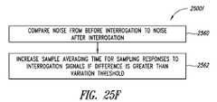
- the control systemmay be further configured to compare at least one noise level measured from before a first interrogation portion of the cycle a noise level measured after the first interrogation portion of the cycle; and increase the sample averaging time for sampling responses to interrogation signals if a result of the comparison indicates a variation in excess of a variation threshold.
- the control systemmay be further configured to determine the set of noise cancellation factors for each of the number of antenna channels by, for each respective antenna channel averaging the measured levels of ambient noise received on all the antenna channels other than the respective antenna channel for which the noise cancellation factor is being determined.
- the antennasmay be radiolucent, and may further include the patient support structure selected from the group consisting of: an operating table, a patient bed, a mattress, a pad and a sheet.
- a method to detect transponder tagged objects which are used during medical proceduresmay be summarized as including for each of at least three antennas spaced at intervals along at least a portion of a length of a patient support structure, successively transmitting a number of interrogation signals via respective ones of the antennas; and monitoring at least the other ones of the antennas for a response to the interrogation signals in a period following the transmission of the interrogation signal and before transmitting another number of interrogation signals via a next one of the antennas.
- Successively transmitting a number of interrogation signals via respective ones of the antennasmay include transmitting the interrogation signals from all of the antennas, one at a time, and monitoring at least the other ones of the antennas for a response to the interrogation signals may include monitoring all of the antennas in the plurality of antennas for a response to each of the interrogation signals.
- Successively transmitting a number of interrogation signals via respective ones of the antennasmay include transmitting the interrogation signals from all of the antennas in the plurality of antennas, one at a time, and monitoring at least the other ones of the antenna for a response to the interrogation signals may include monitoring all of the antennas except the antenna from which a most recent interrogation signal was transmitted for a response to the most recent interrogation signal.
- the methodmay further include measuring a level of ambient noise detected via a plurality of the antennas during a noise detection portion of a cycle, the noise detection portion temporally spaced from any preceding interrogation portions of the cycle such that transponders, if any, are not responding to any electromagnetic interrogation signals transmitted during any preceding interrogation portions of the cycle; determining a set of noise cancellation factors for each of a number of antenna channels; determining a sample averaging time for sampling noise based on the measured level of ambient noise; determining a sample averaging time for sampling responses to interrogation signals based on the measured level of ambient noise; averaging noise corrected samples of noise sampled for the determined noise sample averaging time during the noise detection portion of the cycle; and wherein successively transmitting a number of interrogation signals via respective ones of the antennas includes transmitting the number of electromagnetic interrogation signals via one of the antennas during an interrogation portion of the cycle that follows the noise detection portion; and monitoring at least the other ones of the antennas for a response to the
- the methodmay further include comparing averaged noise corrected samples of responses to the interrogation signals to at least one transponder detection threshold; and iterating through each of the antennas if averaged noise corrected samples of responses to interrogations signals does not satisfy the at least one transponder detection threshold.
- the methodmay further include providing a notification of detection of a transponder if the averaged noise corrected samples of responses to interrogations signals does satisfies the at least one transponder detection threshold an N th time, where N is greater than 1.
- the methodmay further include comparing at least one noise level measured from before a first interrogation portion of the cycle a noise level measured after the first interrogation portion of the cycle; and increasing the sample averaging time for sampling responses to interrogation signals if a result of the comparison indicates a variation in excess of a variation threshold.
- Determining the set of noise cancellation factors for each of the number of antenna channelsmay include, for each respective antenna channel averaging the measured levels of ambient noise received on all the antenna channels other than the respective antenna channel for which the noise cancellation factor is being determined.
- Successively transmitting a number of interrogation signalsmay include successively transmitting the interrogations signals at a number of different frequencies at a number of different times.
- An apparatus to detect transponder tagged objects which are used in performing medical proceduresmay be summarized as including a patient support structure that is sized to support a patient; and at least three antennas positioned along at least a portion of a length of the patient support structure, each of the antennas positioned along the length of the patient support structure radiolucent to X-ray frequency electromagnetic energy, and each of the antennas having a respective range, the ranges of the antennas in each neighboring pair of antennas at least partially overlapping.
- the patient support structuremay be elongated having a longitudinal axis and the antennas are coil antennas, at least some of the coil antennas arranged successively along the longitudinal axis.
- a portion of each successive one of the antenna coilsmay be arranged successively along the longitudinal axis of the surgical table with a projected area that overlaps a portion of a projected area of at least one neighboring one of the antenna coils.
- the patient support structuremay have at least one X-ray film receiving receptacle and the antennas are positioned between a patient support surface of the patient support structure and the at least one X-ray film receiving receptacle.
- the antennasmay each include a respective stripe-line aluminum coil having a number of windings, each stripe-line aluminum coil has a thickness that is not greater than 200 microns. Each stripe-line aluminum coil may have a thickness that is not greater than 100 microns.
- the antennasmay be carried by the patient support structure on, in or under a patient support surface, and may further include at least one pad that overlies at least one of the antennas.
- the apparatusmay further include a control system communicatively coupled to the antennas and configured to successively transmit an interrogation signal via respective ones of the antennas and to monitor at least the other ones of the antennas for a response to the interrogation signal in a period following the transmission of the interrogation signal and preceding a transmission of another interrogation signal.
- a control systemcommunicatively coupled to the antennas and configured to successively transmit an interrogation signal via respective ones of the antennas and to monitor at least the other ones of the antennas for a response to the interrogation signal in a period following the transmission of the interrogation signal and preceding a transmission of another interrogation signal.
- the apparatusmay further include a pedestal that supports the patient support structure, wherein the control system is at least partially housed in the pedestal.
- the apparatusmay further include at least one antenna port carried by the patient support structure, the at least one antenna port communicatively coupled to at least one of the antennas and communicatively coupleable to the control system.
- the apparatusmay further include at least one visual indicator carried by the patient support structure, the at least one visual indicator communicatively coupled to the control system and operable thereby to produce visual indications indicative of responses to the interrogation signals; and at least one user switch carried by the patient support structure, the at least one switch communicatively coupled to the control system and operable thereby to control at least one aspect of an operation of the control system.
- the patient support structuremay be at least one of a pad or a mattress that carries the antennas on at least one of an exterior or an interior thereof, and the at least one of the pad or the mattress may include at least one communications interface to provide selectively decoupleable communicative coupling with at least some of the antennas.
- the at least one of the pad or the mattressmay have a compliant inner portion and an outer cover that at least partially surrounds the compliant inner portion and which is impervious to bodily fluids, the compliant inner portion and the outer cover including radiolucent materials that can withstand multiple sterilization cycles.
- the patient support structuremay be a sheet that carries the antennas on at least one of an exterior or an interior thereof, the sheet including at least one communications interface that provides communicative coupling with at least some of the antennas.
- the apparatusmay further include a number of sensors carried by the patient support structure, the sensors responsive to a respective force exerted by a respective portion of the patient. Each of the sensors may be communicatively coupled to provide a signal indicative of the respective force exerted by the respective portion of the patient.
- the apparatusmay further include a gel carried by the patient support structure at least at a number of locations that correspond to a number of defined locations of the patient when the patient is supported by the patient support structure.
- a systemmay be summarized as including a transponder tag coupled to a medical supply item, the transponder tag configured to wirelessly receive electromagnetic energy in the form of a number of interrogation signals and to emit a response to the interrogation signal by radiating electromagnetic energy; an array of antennas located in a medical procedure environment in which medical procedures are performed; and a controller communicatively coupled to the array of antennas and configured to perform a transponder detection cycle that includes a number of noise detection portions and a number of interrogation portions temporally spaced from the noise detection portions, during which the controller: monitors at least two of the antennas of the array of antennas for an ambient noise in the medical procedure environment during the noise detection portions of the transponder detection cycle, the noise detection portions spaced sufficiently from the interrogation portions that the transponder is not emitting a response detectable by the controller to any previous interrogation signals; emits a number of interrogation signals from each of at least two of the antennas of the array of antennas, successively, during a number of transmission
- the controllermay monitor at least two antennas for any responses to the interrogation signals during a number of detection periods of the interrogation portions of the transponder detection cycle by monitoring all antennas of the antenna array.
- the controllermay monitor at least two antennas for any responses to the interrogation signals during a number of detection periods of the interrogation portions of the transponder detection cycle by monitoring all antennas of the antenna array except the antenna that emitted a most recent one of the interrogation signals.
- the controllermay be further configured to determine a respective noise estimation for each antenna and to compensate any responses received via the antenna using the respective noise estimation.
- the controllermay be further configured to determine a respective noise estimation for each antenna based on noise monitored on a number of the antennas of the antenna array other than the antenna for which the noise estimation is being determined and to compensate any responses received via one of the antennas using the respective noise estimation for the antenna.
- the antennas of the antenna arraymay be physically coupled to a light fixture positioned above a patient support structure.
- the antennas of the antenna arraymay be physically coupled to the patient support structure.
- the antennas of the antenna arraymay be physically coupled to a curtain adjacent to the patient support structure.
- the systemmay further include a hand held wand antenna communicatively coupled to the controller to emit an number of interrogation signals and to monitor for a number of responses to interrogation signals.
- An apparatusmay be summarized as including at least one electrically insulative substrate; and a first plurality of antennas distributed along at least a portion of the at least one insulative substrate, each antenna comprising at least one coil with a plurality of windings and composed of a plurality of segments electrically coupled in series to one another, the segments of each antenna carried on at least two different layers and electrically connected through at least one via, the segments on a first layer laterally spaced apart from one another with respect to a longitudinal axis of the coils to form gaps between successively adjacent ones the segments on the first layer, and the segments on at least a second layer laterally spaced apart from one another to form gaps between successively adjacent ones of the segments on the second layer, the segments on the second layer located directly below the gaps formed between the successively adjacent ones of the segments on the first layer.
- the segmentsmay have a width and the gaps may have a width approximately equal to the width of the segments such that any attenuation of electromagnetic radiation by the segments may be approximately constant in an area enclosed between an outer perimeter and an inner perimeter of each of the antennas.
- Each antennamay include two coils, a first coil composed of segments on the first layer and the second coil composed of segments on the second layer, and a single electrical connection that electrically connects a distal end of the first coil to a distal end of the second coil through the at least one via.
- the apparatusmay further include a controller communicatively coupled to the antennas and configured to drive the antennas to emit a number of electromagnetic interrogation signals to provide energy to a transponder, the controller being further configured to monitor at least some of the antennas for any electromagnetic responses from the transponder to the interrogation signals.
- a controllercommunicatively coupled to the antennas and configured to drive the antennas to emit a number of electromagnetic interrogation signals to provide energy to a transponder, the controller being further configured to monitor at least some of the antennas for any electromagnetic responses from the transponder to the interrogation signals.
- the apparatusmay further include a hand held wand antenna communicatively coupled to the controller to emit a number of interrogation signals and to monitor for a number of responses to interrogation signals.
- a hand held wand antennacommunicatively coupled to the controller to emit a number of interrogation signals and to monitor for a number of responses to interrogation signals.
- Theremay be from six to eight antennas in the first plurality of antennas.
- the first plurality of antennasmay be arranged in a substantially non-overlapping configuration.
- the apparatusmay further include a second plurality of antennas spaced longitudinally from the first plurality of antennas and which overlap at least some of the antennas of the first plurality of antennas. There may be from six to eight antennas in the first plurality of antennas and from two to four antennas in the second plurality of antennas.
- the at least one electrically insulative substratemay be part of a patient support structure.
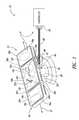
- FIG. 1is a schematic diagram showing an environment in which a medical procedure is performed, for example a surgical environment including a table, bed or other structure to carry or support at least a portion of a patient, that includes a plurality of antennas, and a controller communicatively coupled to the antennas an interrogation and detection system to detect an object tagged with a transponder in a patient, according to one illustrated embodiment.
- a surgical environmentincluding a table, bed or other structure to carry or support at least a portion of a patient, that includes a plurality of antennas, and a controller communicatively coupled to the antennas an interrogation and detection system to detect an object tagged with a transponder in a patient, according to one illustrated embodiment.
- FIG. 2a top plan view of the table, bed or other structure of FIG. 1 showing the plurality of antennas, according to one illustrated embodiment.
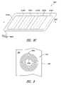
- FIG. 3is a top plan view of the table, bed or other structure of FIG. 1 showing approximate ranges of each of the antennas of FIG. 2 .
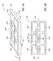
- FIG. 4is a top plan view of a patient support structure showing a number of antennas on a patient support surface and a number of antennas on an opposed surface, according to another illustrated embodiment.
- FIG. 5Ais a side elevational view of the patient support structure of FIG. 4 .
- FIG. 5Bis a cross-sectional view of the patient support structure of FIG. 4 taken along section line 6 of FIG. 4 .
- FIG. 6Ais a top plan view of a support structure showing a number of antennas on a patient support surface and a number of antennas on an opposed surface, according to yet another illustrated embodiment.
- FIG. 6Bis a cross-sectional view of the patient support structure of FIG. 6A taken along section line 7 of FIG. 6A .
- FIG. 6Cis a partial isometric view of the patient support structure of FIGS. 6A and 6B , enlarged to illustrated electrically conductive paths or traces of the antennas.
- FIG. 7is a cross-sectional view of a patient support structure having recesses in which the antennas are received, according to another illustrated embodiment.
- FIG. 8Ais a top plan view of a patient support structure in the form of a bed or an operating table showing a number of antennas arranged in a non-overlapping relationship, according to another illustrated embodiment.
- FIG. 8Bis a top plan view of a patient support structure in the form of a mattress or pad showing a number of antennas arranged in a non-overlapping relationship, according to another illustrated embodiment.
- FIG. 8Cis a top plan view of a patient support structure in the form of a sheet showing a number of antennas arranged in a non-overlapping relationship, according to another illustrated embodiment.
- FIG. 9is an enlarged top plan view of an antenna according to one illustrated embodiment, where the antenna is formed from multiple coils of a conductive material that is radiolucent.
- FIG. 10Ais an enlarged top plan view of an antenna according to one illustrated embodiment, wherein the antenna is formed of a top coil of conductive material and a bottom coil of conductive material.
- FIG. 10Bis an enlarged top plan view of the top coil of the antenna FIG. 10A .
- FIG. 10Dis an enlarged top plan view of the bottom coil of the antenna FIG. 10A .
- FIG. 10Dis a cross-sectional view of a portion of a patient support structure carrying the top and bottom coils of the antenna of FIG. 10A , according to one illustrated embodiment.
- FIG. 10Eis a cross-sectional view of a patient support structure with a plurality of antennas, according to another illustrated embodiment.
- FIG. 10Fis a top plan view of a patient support structure comprising a plurality of antennas, according to still another illustrated embodiment.
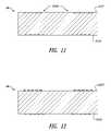
- FIG. 11is a cross-sectional view of a portion of a patient support structure with an antenna carried in opposed surfaces thereof, according to yet still another illustrated embodiment.
- FIG. 12is a cross-sectional view of a portion of a patient support structure an antenna of FIG. 10A carried on opposed surfaced thereof, according to even another illustrated embodiment.
- FIG. 13Ais a schematic diagram showing a surgical table with a plurality of antennas and a controller positioned in a pedestal of the surgical table, according to another illustrated embodiment.
- FIG. 13Bis a schematic diagram showing a bed such as a patient bed used in an environment where medical procedures are preformed, the bed including a plurality of antennas and a controller positioned on a frame of the bed, according to another illustrated embodiment.
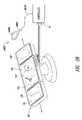
- FIG. 14Ais a side elevational view of an overhead light fixture for use in a medical procedure and a light shade with several antennas supported by the light fixture, according to one embodiment in which the light shade is shown in a retracted position or configuration of FIG. 10A .
- FIG. 14Bis a side elevational view of the light fixture and a light shade in which the light shade is shown in an extended position or configuration.
- FIG. 14Cis a side elevational view of a light fixture for use in a medical procedure and a light shade with several antennas according to another illustrated embodiment.
- FIG. 15Ais an isometric view of a track and a curtain or drape containing several antennas, according to one illustrated embodiment.
- FIG. 15Bis a side elevational view of a sheet containing several antennas and configured to be hung from a support according to one embodiment.
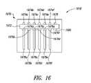
- FIG. 16is a schematic diagram of a controller, according to one illustrated embodiment, including a motherboard and a plurality of plug-in boards, one for each of the antennas.
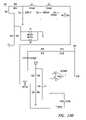
- FIG. 17is a schematic diagram of a portion of a control system of the interrogation and detection system, according to one illustrated embodiment.
- FIG. 18is a schematic diagram of a software configuration of the interrogation and detection system, according to one illustrated embodiment.
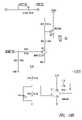
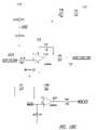
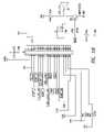
- FIGS. 19A-19Iare an electrical schematic diagram of the interrogation and detection system including a control circuit and antenna, according to one illustrated embodiment.
- FIG. 20is a timing diagram illustrating a method of frequency hopping, according to one illustrated embodiment.
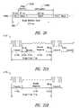
- FIG. 21Ais a timing diagram illustrating pulsed timing, according to one illustrated embodiment.
- FIG. 21Bis a timing diagram illustrating pulsed timing, according to another illustrated embodiment.
- FIG. 22is a timing diagram showing activation of a pair of transistors of the control circuit in a push-pull configuration to drive the antenna, according to one illustrated embodiment.
- FIG. 23Ais a flow diagram of a method of operating an interrogation and detection system, according to one illustrated embodiment.
- FIG. 23Bis a flow diagram of a method of monitoring all antennas for a response to an interrogation signal, according to one illustrated embodiment.
- FIG. 23Cis a flow diagram of a method of monitoring all antennas except a transmitting antenna for a response to an interrogation signal, according to one illustrated embodiment.
- FIG. 24Ais a high level flow diagram of a method of operating an interrogation and detection system to detect transponders, according to one illustrated embodiment.
- FIG. 24Bis a low level flow diagram of a method of operating an interrogation and detection system to sample noise and responses and to adjust sampling times and perform noise correction, according to one illustrated embodiment, the method useful with the method of FIG. 24A .
- FIG. 24Cis a flow diagram of a method of operating an interrogation and detection system to determine whether a transponder has been detected, according to one illustrated embodiment, the method useful with the method of FIG. 24A .
- FIGS. 25A-25Fare flow diagrams of methods of operating an interrogation and detection system by measuring and/or compensating for noise, according to various illustrated embodiments, the methods useful with the method of FIG. 24A .
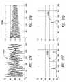
- FIG. 26Ais a graph showing a measured or sampled response versus time without noise cancellation where a noise source is present but no transponder is present, according to one illustrated embodiment.
- FIG. 26Bis a graph showing a measured or sampled response versus time with noise cancellation where a noise source is present but not transponder is present, according to one illustrated embodiment.
- FIG. 26Cis a graph showing a measured or sampled response versus frequency without noise cancellation where a noise source is present but no transponder is present, according to one illustrated embodiment.
- FIG. 26Dis a graph showing a measured or sampled response versus frequency with noise cancellation where a noise source is present but not transponder is present, according to one illustrated embodiment.
- FIG. 27Ais a graph showing a measured or sampled response versus time without noise cancellation where a noise source and a transponder are present, according to one illustrated embodiment.
- FIG. 27Bis a graph showing a measured or sampled response versus time with noise cancellation where a noise source and a transponder are present, according to one illustrated embodiment.
- FIG. 27Cis a graph showing a measured or sampled response versus frequency without noise cancellation where a noise source and a transponder are present, according to one illustrated embodiment.
- FIG. 27Dis a graph showing a measured or sampled response versus frequency with noise cancellation where a noise source and a transponder are present, according to one illustrated embodiment.
- FIG. 28is an isometric view of a surgical environment including an operating table that carries a plurality of antennas, a hand held wand antenna, and a controller according to one illustrated embodiment.
- antennase.g., six antennas. Successive ones of the antennas may be used to transmit an interrogation signal, while two or more antennas are monitored for a response to the interrogation signal.
- Suchmay provide significant advantages over more conventional methods, for example motion based methods that employ motion (e.g., sweeping) of an antenna (e.g., wand) over a patient. For instance, this allows the transmit and receive paths to the transponder to be different from one another (e.g., transmit path is from a first antenna to a transponder, while the receive path is from the transponder to a second antenna).
- the path length to the transpondermay be shortened in many configurations, thus improving the signal. For instance, when using a single antenna to both transmit an interrogation signal and to receive a response to the interrogation signal, the power of the received signal is equal to about the 6 th root of the input power. However, when using multiple antennas to transmit and receive over the same area, interrogation path length in one direction may be shorter. Another advantage is that all scan time is averaged, allowing a longer noise time averaging (e.g., 10 seconds) as opposed to motion based scanning, where integration time may be limited (e.g., about 0.25 seconds per sample).
- a representative value of noise samples measured over a plurality of antennasmay be employed to determine noise to be removed from noise plus signals received at one of the antennas, thereby advantageously lowering a noise floor and/or increasing range or performance.
- the various disclosed embodimentsmay provide significantly better performance.
- FIGS. 1 and 2show a medical procedure environment 10 in which medical procedures are performed, for example a surgical environment in which surgeries are performed, a patient room in which child birth deliveries or other medical procedures are performed or a physician's office, etc.
- the medical procedure environment 10includes a table (e.g., surgical table), bed, or other structure 12 which can carry a patient or portion thereof and an interrogation and detection system 14 .
- the interrogation and detection system 14includes a plurality of antennas 16 a - 16 f (collectively 16 , shown in broken line in FIG. 1 to indicate that such are hidden in that view) which are carried by the patient support surface 12 .
- the interrogation and detection system 14also includes a controller 18 communicatively coupleable to the antennas 16 by one or more wired or wireless communication paths, for example coaxial cable 20 . As discussed in detail below, the interrogation and detection system 14 is operable to ascertain the presence or absence of objects 22 a , 22 b (collectively 22 ) tagged with transponders 24 a , 24 b (collectively 24 ), which may be in or on a patient (not shown).
- the table, bed or other structure 12may include a patient support structure 26 and a pedestal or base 28 which supports the patient support structure 26 .
- the patient support structure 26should have dimensions sufficient to support at least a portion of a patient during a medical procedure, for instance during surgery, child birth, etc. Hence, the patient support structure 26 may have a length of six feet or more and a width of two feet or more.
- the patient support structure 26may have two or more articulated sections 26 a - 26 c , as illustrated in FIG. 1 or 2 , or may be a unarticulated or unitary structure as illustrated in FIGS. 4 , 7 and 9 .
- Hinges 30 a , 30 b (collectively 30 ) or other coupling structuresmay couple the articulated sections 26 a - 26 c .
- the hinges 30may, for example, be located along a longitudinal axis 32 of the patient support structure 26 at locations that would approximate the anticipated position of a between a patient's legs and torso and between the patient's
- the patient support structure 26is preferably made of a rigid material and is preferably radiolucent.
- Various radiolucent materialsmay be employed, for instance carbon fiber or radiolucent plastics.
- the patient support structure 26may be molded from plastics such as an acrylic or a phenolic resin (e.g., commercially available under the trademark SPAULDITE®).
- the patient support structure 26may include a frame.
- the framemay be made of a metal which may not be radiolucent. In such embodiments, the frame preferably makes up a small percentage of the total area of the patient support structure 26 .
- the patient support structure 26may be capable of withstanding multiple cycles of sterilization (e.g., chemical, heat, radiation, etc.).
- sterilizatione.g., chemical, heat, radiation, etc.
- a large variety of surgical tables, patient beds and other structures capable of carrying a patient or a portion of a patientare commercially available. Many of these commercially available structures include electric motors and electronics. Typically, there is no or minimum regulation of non-ionizing electromagnetic radiation generated by such electric motors and electronics. Hence, many environments 10 in which medical procedures are performed tend to be electromagnetically noisy environments.
- the table, bed or other structure 12may include one or more mattresses or pads 34 a - 34 c (collectively 34 ), and/or may include one or more sheets (not shown in FIG. 1 for sake of clarity of illustration).
- the mattresses or pads 34 and/or sheetsmay overlie the antennas 16 .
- the mattresses or pads 34may take a variety of forms, and may be disposable, or may be capable of withstanding multiple cycles of sterilization (e.g., chemical, heat, radiation, etc.).
- the mattresses or pads 34are preferably radiolucent.
- the mattresses or pads 34may take a conventional form, for example cotton, open cell or a closed cell foam rubber, with or without an appropriate cover.
- the mattresses or pads 34may include one or more bladders (e.g., dual layer urethane envelope) to receive a fluid (e.g., air, water, etc.) to selectively inflate one or more portions of the mattresses or pads 34 , and/or to control a temperature of one or more portions of the mattresses or pads 34 .
- the fluidshould be radiolucent.
- the mattresses or pads 34may include a cushioning gel or polymer material (e.g., polymer foam). Such may alleviate pressure points, reducing the formation of sores or ulcers, particularly during long medical procedures.
- the cushioning gel or polymer materialshould be radiolucent.
- the cushioning layermay include recesses or voids formed at locations selected to accommodate a patient's anatomy.
- the mattresses or pads 34may be detachably secured to the patient support structure 26 via various fasteners, for instance ties, or hook and loop fastener commonly available under the trademark VELCRO®.
- the pedestal or base 28may be fixed, or may be moveable.
- the pedestal or base 28may include one or more actuators (e.g., motors, pumps, hydraulics, etc.) and/or drive mechanisms (e.g., gears, mechanical couplings) or linkages (not shown) that allow a position and/or orientation of the patient support structure 26 to be adjusted.
- the pedestal or base 28may telescope to allow the patient support structure 26 to be mechanically raised and lowered.
- the pedestal or base 28may allow the patient support structure 26 to be mechanically tilted or rotated about an axis that is perpendicular to a patient support surface 37 of the patient support structure 26 .
- portions of one or more of the antennas 16may overlap.
- the antennasare coil antennas, each formed of one or more coils
- a portion of an area enclosed by an outermost coil of each antenna 16may overlap a portion of an area enclosed by an outermost coil of a neighboring antenna 16 .
- the area enclosed or enclosed areamay be an area enclosed by a normal or perpendicular projection of a perimeter defined the outermost coil of the respective antenna 16 .
- neighboring antennas 16may be electrically insulated from one another by one or more electrically insulating layers or substrates.
- successively adjacent antennas 16may be carried one opposite surfaces (e.g., opposed outer surfaces, or multiple inner surfaces, or one or more outer and inner surfaces) of a single substrate.
- the antennasmay advantageously be radiolucent, for example being formed of a radiolucent material (e.g., substantially transparent to X-ray or Gamma ray radiation) or a material that at a thickness employed is substantially radiolucent.
- a radiolucent materiale.g., substantially transparent to X-ray or Gamma ray radiation
- a material that at a thickness employedis substantially radiolucent.
- an electrically conductive trace of aluminumhaving a thickness of 200 microns or less sufficiently passes X-rays to be considered radiolucent. More preferably, an aluminum trace having a thickness of 30 microns sufficiently passes X-rays such that even a stack or overlapping portions of three coils (combined thickness under 100 microns) to be radiolucent.
- An antennamay be considered radiolucent if it is not detectable by an radiologist in an X-ray produced via 10 kV to 120 kV X-ray machine, or preferably a 40 KV X-ray machine in conjunction with a standard 12 inch X-ray image intensifier.
- An antennamay be considered radiolucent if a coil includes thirty turns or windings and is not detectable by an radiologist in an X-ray.
- the patient support structure 26may include one or more film receiving receptacles 29 (only one called out in FIG. 1 ).
- the film receiving receptacles 29may be spaced relatively below a patient support surface 37 of the patient support structure 26 .
- the film receiving receptacles 29are sized, dimensioned and/or positioned to receive film, for example X-ray film.
- the film receiving receptacles 29my be sized and/or dimensioned to receive a film tray or other film holder (not illustrated) which holds the film.
- radiolucent materialssuch advantageously allows a patient X-ray images or other radiological images of the patient to be produced, generated or made, while the patient is supported by the patient support structure 26 .
- the term radiolucentmeans substantially transmissive to energy in the X-ray portion of the electromagnetic spectrum, that is passing sufficient X-ray energy to produce an X-ray image at standard power levels and standard conditions employed in conventional medical imaging.
- the table(e.g., surgical table), bed or other structure 12 may include an interrogation and detection system interface 36 .
- the interrogation and detection system interface 36may include one or more communications ports 38 that allow communicative coupling to be selectively or detachably made between the antennas 16 and the controller 18 .
- Such communications ports 38may, for example, take the form of coaxial connectors, or other communications connectors.
- Interrogation and detection system interface 36may include one or more output devices to provide indications to a user.
- the interrogation and detection system interface 36may include one or more visual indicators 40 (only one called out in FIGS. 1 and 2 ) to provide indications of a presence and/or an absence of an object.
- Suchmay also provide a visual indication that is indicative of a status of a scanning operation by the interrogation and detection system 14 , for instance scanning started, scanning completed, and/or occurrence of an error condition.
- the visual indicators 40may take a variety of forms, for example light sources of one or more colors. Light sources may include incandescent lights, light emitting diodes (LEDs), organic light emitting diodes (OLEDs), and/or liquid crystal displays (LCDs).
- the interrogation and detection system interface 36may include one or more aural indicators 42 to provide aural indications of a presence and/or an absence of an object and/or a status of a scan operation or occurrence of an error condition.
- the aural indicator 42may, for example, take the form of one or more speakers.
- the interrogation and detection system interface 36may include one or more switches 44 that allow input to be provided to the controller 18 . Switches 44 may, for example, allow a user to turn ON the interrogation and detection system 14 , start a scan operation, stop a scan operation, adjust a sensitivity of the scanning, adjust one or more frequencies, select or adjust an output type (e.g., type of visual alert, type of aural alert) or level (e.g., brightness, sound level or volume, etc.).
- an output typee.g., type of visual alert, type of aural alert
- levele.g., brightness, sound level or volume, etc.
- the objects 22may take a variety of forms, for example instruments, accessories and/or disposable objects useful in performing medical procedures, for example surgical procedures, child birth delivery procedures, and/or other medically related procedures.
- some objects 16 amay take the form of scalpels, scissors, forceps, hemostats, and/or clamps.
- some objects 22 bmay take the form of sponges (e.g., surgical sponges), gauze and/or padding.
- the objects 22are tagged, carrying, attached or otherwise coupled to a respective transponder 24 .
- Some embodiments of the interrogation and detection system 14 disclosed hereinare particularly suited to operate with transponders 26 which are not accurately tuned to a chosen or selected resonant frequency. Consequently, the transponders 24 do not require high manufacturing tolerances or expensive materials, and thus may be inexpensive to manufacture.
- Transponders 24may include a miniature ferrite rod with a conductive coil wrapped about an exterior surface thereof to form an inductor (L), and a capacitor (C) coupled to the conductive coil to form a series LC circuit.
- the conductive coilmay, for example, take the form of a spiral wound conductive wire with an electrically insulative sheath or sleeve.
- the transponder 24may include an encapsulation that encapsulates the ferrite rod, conductive coil, and capacitor.
- the encapsulantmay be a bio-inert plastic, that protects the ferrite rod, conductive coil and/or capacitor from pressure and/or from fluids, for example bodily fluids.
- the ferrite rodmay include a passage sized to receive a physical coupler, for example a bonding tie or string.
- the bonding tie or stringmay take the form of an elastomeric x-ray opaque flexible elongated member, that may be used to attach the transponder 24 to various types of objects 22 , for example surgical sponges.
- the transponder 24may have a length of about 8 millimeters and a diameter of about 2 millimeters. Employing such small dimensions ensures that the transponder 24 does not impede deformation of objects 16 such as sponges.
- the transponder 24may include an optional diode (not shown), to protect against over-voltage occurrences caused by other electronic instruments.
- the transponders 24may be attached to hemostats, scissors, certain forms of forceps, and the like. In some embodiments, the transponders 24 may be coupled to the object 22 by way of a clamp or holder. In some embodiments, the transponders 24 may be retained within a cavity of the holder. In some embodiments, the holder may be fashioned of a durable deformable material, such as surgical grade polymer, which may be deformed to clamp securely onto the finger or thumbhole of an instrument. In other embodiments, the transponders 24 may be attached to objects 22 by way of pouches fashioned of sheet material (e.g., surgical fabric) surrounding the transponder 24 . The transponder 24 is retained within the pouch, and in some embodiments the pouch may be sewn or otherwise sealed.
- a durable deformable materialsuch as surgical grade polymer
- the medical provider 12may use the switches 44 to cause a scan of the patient 18 , for instance jut before closing during surgery, in order to detect the presence or absence of the transponder 26 , and hence an object 16 .
- FIG. 3shows approximate ranges R 1 -R 6 for the six antennas 16 of the embodiment of FIGS. 1 and 2 .
- FIG. 3is illustrative and does not necessarily represent actual ranges.
- the illustrated ranges R 1 -R 6(collectively R) show that the ranges R 1 -R 6 are typically larger than the area of the antennas 16 .
- Ranges R 1 -R 6may be affected by a variety of factors, including the power of the interrogation signal, distance between the transponders 24 and the antennas 16 , and/or the sensitivity and/or impedance matching between the transponders 24 and interrogation and detection system 14 .
- Many of the ranges R 1 -R 5overlap neighboring ranges R 1 -R 5 , although in this illustrated embodiment one range R 6 does not overlap any other range R 1 -R 5 . In other embodiments, all ranges overlap. Alternatively, none of the ranges may overlap.
- Other arrangements of antennas 16 and/or ranges Rare of course possible.
- FIGS. 4 , 5 A and 5 Bshow a patient support structure 626 , according to another illustrated embodiment.
- the patient support structure 626may, for example, be part of a table, for instance a surgical table, part of a bed or another structure designed to carry a patient or portion of a patient.
- the patient support structure 626is a non-articulated, single piece or unitary structure. While illustrated as a single, unitary construction, the patient support structure 626 may be formed of two or more sections, which may or may not be articulated.
- the patient support structure 626is formed as a substrate 650 having a patient support surface 637 and an opposed surface 652 that is opposed from the patient support surface 637 .
- the substrate 650may be formed of one or more layers.
- the substrate 650may be a composite material.
- the substrate 650may, for example, be formed as a resin impregnated carbon fiber structure, which may advantageously omit any metal or ferrous metal structural elements. Alternatively, the substrate 650 may minimize the use of any metal or ferrous metal structural elements and locate any metal or ferrous metal structural elements at the peripheries of the substrate 650 .
- a first set of antennas 616 a , 616 c , 616 e , 616 gare positioned on the patient support surface 637
- a second set of antennas 616 b , 616 d , 616 fare positioned on the opposed surface 652 .
- Suchallows neighboring ones of the antennas (collectively 616 ), or portions thereof, to overlap, while electrically insulating each antenna 616 from one another.
- one or more of the antennas 616could be carried on one or more inner layers of the patient support structure 650 where the patient support structure 650 is formed of two or more layers, for instance as a laminate structure.
- FIGS. 6A-6Cshow a patient support structure 626 and antennas 616 a - 616 h (collectively 616 ), according to another illustrated embodiment, wherein individual ones of the electrically conductive paths or traces of the antennas 616 are visible.
- the patient support structure 626may, for example, be part of a table, for instance a surgical table, part of a bed (e.g., patient or hospital bed) or another structure designed to carry a patient or portion of a patient on which a medical procedure may be performed.
- the patient support structure 626is a non-articulated, single piece or unitary structure. While illustrated as a single, unitary construction, the patient support structure 626 may be formed of two or more sections, which may or may not be articulated.
- the patient support structure 626is formed as a substrate 650 having a patient support surface 637 and an opposed surface 652 that is opposed from the patient support surface 637 .
- the substrate 650may be formed of one or more layers.
- the substrate 650may be a composite material.
- the substrate 650may, for example, be formed as a resin impregnated carbon fiber structure, which may advantageously omit any metal or ferrous metal structural elements. Alternatively, the substrate 650 may minimize the use of any metal or ferrous metal structural elements and locate any metal or ferrous metal structural elements at the peripheries of the substrate 650 .
- the patient support structure 626carries antennas 616 thereon and/or therein. As best illustrated in FIGS. 6A and 6B , the antennas can be treated as two sets. A first set of antennas 616 a - 616 f arranged generally adjacent one another in an array of two rows on either side of a longitudinal axis 630 and three columns spaced along the longitudinal axis 630 . These antennas 616 a - 616 f do not overlap with one another. These antennas 616 a - 616 f substantially extend the full length and width of the patient support structure 628 .
- these antennas 616 a - 616 fmay be spaced inwardly from a perimeter of the patient support structure, for example where the range of the antennas 616 a - 616 f sufficiently covers the area of the patient support structure 626 .
- a second set of antennas 616 g , 616 hare arranged generally adjacent one another in an array of one row and two columns. These antennas 616 g , 616 h do not overlap with one another, however these antennas 616 g , 616 h overlap the antennas 616 a - 616 f of the first set when viewed from above the patient support structure 626 .
- These antennas 616 g , 616 henhance the overall coverage of the entire area of the patient support structure 626 and volume spaced generally there above.
- one or more of the antennas 616could be carried on a lower outer surface 652 and/or on one or more inner layers of the patient support structure 626 , for instance where the patient support structure 626 is a laminate structure.
- FIG. 6Cshows one embodiment of the antennas 616 , which may allow relatively simple and low cost manufacturing, and which prevents the antennas 616 from electrically shorting one another.
- each antennamay be formed as electrically conductive paths or traces on one or more layers of an electrically non-conductive or insulative substrate, for instance a flexible substrate of circuit board material (e.g. FR4, Kapton).
- the electrically conductive path or tracemay form a coil pattern, hence a coil antenna with multiple windings, as illustrated in FIG. 6C .
- Portions of the electrically conductive path on one end or half of the substratemay be electrically coupled to respective portions of the electrically conductive path on the other end or half of the substrate via electrically conductive material received in a via that extends through a portion or all of the substrate.
- the electrically conductive pathsappear to terminate at a centerline 647 of each antenna, the electrically conductive paths are in fact electrically coupled to adjacent portions across the centerline 647 by way of respective vias.
- the electrically conductive pathmay have change in direction (e.g., 45 degree turn), such that the electrically conductive path spirals inwardly (or outwardly) with each half turn or half winding.
- an electrically non-conductive or electrically insulative materialmay overlie the electrically conductive path on a lower surface or side and/or an upper surface or side of the substrate, to provide electrical insulation between overlying substrates.
- FIG. 7shows a patient support structure 726 , according to another illustrated embodiment.
- the patient support structure 726is formed as a substrate 750 having a patient support surface 737 and an opposed surface 752 that is opposed from the patient support surface 737 .
- the substrate 750may be formed of one or more layers.
- the substrate 750may be a composite material.
- the substrate 750may, for example, be formed as a resin impregnated carbon fiber structure, which may advantageously omit any metal or ferrous metal structural elements.
- the substrate 750may minimize the use of any metal or ferrous metal structural elements and locate any metal or ferrous metal structural elements at the peripheries of the substrate 750 . While illustrated as a single, unitary construction, the patient support structure 726 may be formed of two or more sections, which may or may not be articulated.
- a first set of antennas 716 a , 716 c , 716 e , 716 gare positioned in respective recesses formed in the patient support surface 737
- a second set of antennas 716 b , 716 d , 716 fare positioned in respective recesses formed in the opposed surface 752 .
- Suchallows neighboring ones of the antennas (collectively 716 ) to overlap, while electrically insulating each antenna 716 from one another.
- Suchalso advantageously spaced the antennas 716 of the first and second sets closer together with respect to one another, which may produce more consistent results or performance between the various antennas 716 .
- While illustrated as being carried on outer surfaces of the patient support structure 750one or more of the antennas 716 could be carried on one or more inner layers of the patient support structure 750 where the patient support structure 750 is formed of two or more layers, for instance as a laminate structure.
- FIG. 8Ashows a patient support structure 826 A, according to another illustrated embodiment.
- the patient support structure 826 Ais a non-articulated, single piece or unitary structure. While illustrated as a single, unitary construction, the patient support structure 826 A may be formed of two or more sections, which may or may not be articulated. The patient support structure 826 A may be formed of a variety of materials, for example, the materials of the above described embodiments.
- the patient support structure 826 Acarries a set of antennas 816 Aa- 816 Af (collectively 816 A), which are positioned along a longitudinal axis 830 of the patient support structure 826 A. While illustrated as positioned in non-overlapping fashioned, in some embodiments the antennas 816 A may be positioned in overlapping fashion. While five antennas 816 B are illustrated, the patient support structure 826 A may include a greater or lesser number of antennas 816 A. Consequently, the antennas 816 A may all be carried on the same outer surface (e.g., patient support surface) or inner surface or layer. Thus, may advantageously provide more consistent results or performance between the respective antennas 816 , and/or may simply manufacturing and/or maintenance.
- FIG. 8Bshows a patient support structure, according to another illustrated embodiment.
- the patient support structuretakes the form of a mattress or pad 826 B which may, for example, be used on a table or bed when performing a medical procedure. While illustrated as an articulated structure with two joints or hinges 830 Ba, 830 Bb (collectively 830 B), the mattress or pad 826 B may be formed of a unitary, single piece non-articulated structure.
- the mattress or pad 826 Bmay be reusable, and hence should be capable of withstanding repeated sterilization procedures (e.g., heat, chemical, radiation, etc.). Alternatively, the mattress or pad 826 B may be disposable after a single use.
- the mattress or pad 826 Bmay be formed of a variety of materials, for example, the materials of the above described embodiments of mattresses or pads.
- the mattress or pad 826 Bmay include an outer layer or cover 892 B and an interior 890 B (visible through broken portion of outer layer 892 B).
- the outer layer or cover 892 Bprovides environmental protection to the interior 890 B.
- the interior 890 Bmay, for example, take the form of a conformable interior, which may be made of any variety of materials. Suitable material may, for example, include cotton or a foam material such as a closed or an open cell foam rubber or LATEX®. Alternatively, the conformable interior may take the form of a fluid (e.g., a liquid or a gas).
- the outer layer or cover 892 Bmay be made of cotton, nylon, rayon or other natural or synthetic materials.
- the outer layer or cover 892 Bmay, for example, be impervious to liquids.
- the outer layer or cover 892 Bmay include one or more layers of a rubber, LATEX®, polyvinyl chloride, plastic or other material that is impervious to fluids, for example bodily fluids.
- the mattress or pad 826 Bcarries a set of antennas 816 Ba- 816 Be (collectively 816 B), which are positioned along a longitudinal axis 832 B of the mattress or pad 826 B. While illustrated as positioned in overlapping fashioned, in some embodiments the antennas 816 B may be positioned in non-overlapping fashion. While five antennas 816 B are illustrated, the mattress or pad 826 B may include a greater or lesser number of antennas 816 B. For example, the mattress or pad 826 B may have antennas 816 arranged in a similar fashion to that illustrated in FIGS. 6A-6C .
- the antennas 816 Bmay on opposite sides of a layer on or in the mattress or pad 826 B, or on two or more different layers on or in the mattress or pad 826 B.
- the layer or layersmay be an outer surface (e.g., patient support surface) or an inner surface or layer.
- the mattress or pad 826 Bincludes an interface, such as a connector 894 B, to allow the antennas 816 B to be communicatively coupled to the controller 18 ( FIG. 1 ).
- FIG. 8Cshows a patient support structure, according to another illustrated embodiment.
- the patient support structuretakes the form of a sheet 826 C.
- the sheet 826 Cmay, for example, be used on, over, or in conjunction with a table, bed, frame or other structure during a medical procedure.
- the sheet 826 Cmay be formed of a unitary, single piece of material or a cloth, for example a fabric.
- the clothmay, for example, be woven, knitted, felted, pressed, etc.
- the sheet 826 Cmay be reusable, and hence should be capable of withstanding repeated sterilization procedures (e.g., heat, chemical, radiation, etc.).
- the sheet 826 Cmay be disposable after a single use.
- the sheet 826 Cmay be absorbent or may be impermeable to fluids, for example bodily fluids.
- the sheet 826 Cmay be formed of a variety of materials, for example, cotton, nylon, rayon, or other natural or synthetic fibers.
- the sheet 826 Cmay include one or more layers of a rubber, LATEX®, polyvinyl chloride, plastic or other material that is impervious to fluids, for example bodily fluids.
- the sheet 826 Ccarries a set of antennas 816 Ca- 816 Ce (collectively 816 C), which are positioned along a longitudinal axis 832 C of the sheet 826 C. While illustrated as positioned in overlapping fashioned, in some embodiments the antennas 816 C may be positioned in non-overlapping fashion. While six antennas 816 C are illustrated, the sheet 826 C may include a greater or lesser number of antennas 816 C. For example, the antennas 816 may be arranged on the sheet 826 in an identical or similar fashion as illustrated in FIGS. 6A-6C . The antennas 816 C may be on opposite sides of the sheet 826 C, or on two or more different layers of the sheet 826 C.
- the layer or layersmay be an outer surface (e.g., patient support surface) or an inner surface or layer.
- the sheet 826 Cincludes an interface, such as a connector 894 C, to allow the antennas 816 C to be communicatively coupled to the controller 18 ( FIG. 1 ).
- FIG. 9shows an antenna 916 , according to one illustrated embodiment.
- the antenna 916may, for example, be suitable for use in any of the previously described embodiments.
- the antenna 916may, for example, take the form of an annulus or air-coil formed of coils of conductive material.
- the conductive materialmay, for example, take the form of wire or may take the form of a conductive trace printed or otherwise deposited on an inner layer or an outer surface 952 of a substrate 950 .
- the antenna 916includes ten turns evenly spaced between an inner diameter of about 11 inches and an outer diameter of about 14 inches.
- the antenna 916acts as an inductor. While being formed of a conductive material, the antenna 916 is preferably formed of a radiolucent material.
- the antenna 916may be formed as a thin (e.g., thickness, width) strip line aluminum antenna.
- the antenna 816includes a pair of terminals 854 a , 854 b that provide electrical coupling to the controller 18 ( FIG. 1 ), for example via the ports 38 of interrogation and detection system interface 36 ( FIGS. 1 and 2 ) and the coaxial cable 20 .
- FIGS. 10A-10Cillustrate a coil antenna 1016 according to one embodiment.
- the coil antenna 1016comprises a top coil 1017 (illustrated in isolation in FIG. 10B ) and a bottom coil 1019 (illustrated in isolation in FIG. 100 ).
- the top and bottom coils 1017 , 1019are carried by the patient support surface 26 , the top coil 1017 carried on one layer 1021 a and positioned relatively above the bottom coil 1019 carried on another layer 1021 b .
- the top coil 1017is electrically coupled to the bottom coil 1019 , for example, by a plug of electrically conductive material 1015 in a via.
- the via connecting the top coil 1017 to the bottom coil 1019may comprise a vertical connector of the same material as the coils 1017 , 1019 .
- any suitable conductormay be used to connect the top coil to the bottom coil at the via point.
- the individual windings of the two coilsare also offset from each other laterally along two perpendicular axes in a horizontal plane (i.e., the plane of the drawing sheet FIG. 10A ) that is perpendicular to the longitudinal axis.
- the layers 1021 a , 1021 bmay be opposed outer surfaces of an electrically insulative substrate, one or more inner surfaces of the electrically insulative substrate, or a combination thereof.
- the electrically insulative substratemay be a unitary part of the patient support surface, integral part of the patient support surface or attach or carried by the patient support surface.
- FIG. 10Dshows the coil antenna 1016 carried by a patient support structure 26 , according to one illustrated embodiment.
- Top coil 1017is positioned relatively above the bottom coil 1019 in an interior of the patient support structure 26 .
- the bottom coil 1019is offset from the top coil 1017 vertically along a longitudinal axis 1018 as well as laterally in a horizontal plane which is perpendicular to the longitudinal axis 1018 .
- the individual windings 1021 of the top coil 1017are spaced apart leaving gaps between each winding 1021 .
- the individual windings 1023 of the bottom coil 1019are spaced directly below the gaps between the windings 1021 of the top coil 1017 .
- the windings 1021 , 1023are thus spread in such a way to provide a more even distribution of radiolucence.
- FIG. 10Dillustrates an embodiment in which the windings 1023 are spaced directly below the gaps between windings 1021 without overlapping the windings 1021 in a lateral direction in the horizontal plane. In other embodiments the windings 1023 may instead slightly overlap the windings 1021 . In some embodiments the windings 1021 , 1023 may cross over each other although such crossings may have an adverse effect on radio transparency. Many other configurations of the coils 1017 , 1019 and the windings 1021 , 1023 will be apparent to those of skill in the art and fall within the scope of this disclosure.
- FIG. 10DThe configuration of windings illustrated in FIG. 10D are given only by way of example and do not limit the scope of the disclosure.
- the patient support structure 26 and antenna 1016are not drawn to scale. Relative heights, widths, and separations of the patient support structure 26 and antenna coils 1017 , 1019 may be different in practice than what is shown in FIG. 10D .
- This designmay minimize interference with radiological imagery sources (e.g., X-rays, CAT scans, MRIs) which may be employed while a patient is on the patient support structure 26 .
- Radiological imagingis commonly employed while patients are on the patient support structure 26 , for example during surgery. This may, for example, be performed by positioning an X-ray machine above the patient support structure 26 and positioning an X-ray sensitive film below the patient support structure 26 .
- An X-ray imageis formed by exposing the film to the X-rays through the patient and patient support structure 26 . Any object or material that absorbs or reflects X-rays more than its surroundings will cause an area of contrast in the developed X-ray image.
- portions of the patient support 26 structure that absorb more or less than other portions of the patient support structure 26will appear as a high level of contrast in the developed X-ray image. This can make it difficult to interpret the X-ray image. For this reason it may be beneficial to spread the coils of an antenna, even where nominally radio transparent to reduce the contrast which the antenna may otherwise cause in an X-ray image.
- a coil antenna with many windings which are stacked or layered are above othersmay produce a relatively high contrast and appear in an X-ray image even if a single layer of coil is nominally radio transparent.
- a coil whose windings are spread apart, spread laterally from one another,may also produce relatively large changes in contrast, even where nominally radio transparent.
- the windings of the coilsare positioned to be in adjacent non-overlapping relationship to one another when viewed along the longitudinal axis 1018 .
- Suchcreates an area having a very uniform distribution of antenna material, and hence a very uniform radiological attenuation distribution across that area.
- Suchadvantageously may cause any attenuation to be uniform, reducing the antenna's effect on the radiological image.
- FIGS. 10E and 10Fshow a patient support structure 26 according to one embodiment.
- the patient support structurecarries six antennas 1016 a - 1016 f .
- Each of the antennas 1016 a - 1016 fmay be similar or identical in form to the antenna 1016 illustrated in FIG. 10A-10D .
- the antennas 1016 a - 1016 fare positioned to provide little or no gap between antennas in the lateral directions of the horizontal plane of the patient support surface 26 , while not overlapping. As described above, this configuration may help to reduce areas of sharp contrast in radiological images.
- FIG. 10Eshows the antennas 1016 a - 1016 f embedded within the patient support structure 26 .
- the antennas 1016 a - 1016 fmay not actually be visible from a top view of the support structure 26 .
- FIG. 10Fshows the antennas 1016 a - 1016 f from the top view to illustrate the relative positions of the antennas 1016 a - 1016 f .
- the number and configuration of coils, as well as the number and configuration of the winding forming those coils, shown in FIG. 10Fis not meant to be limiting. In practice there may be a greater or lesser number of coils and/or a greater or lesser number of windings. In practice, the windings are typically not independent loops, but are illustrated as such in FIG. 10F for ease of illustration.
- FIG. 11shows a patient support structure carrying an antenna 1116 , according to another illustrated embodiment.
- the antenna 1116comprises a top coil 1117 and a bottom coil 1119 as previously described.
- the top coil 1117comprises windings 1121
- the bottom coilcomprises windings 1123 .
- the windings 1121 , 1123are laterally offset from each other in two perpendicular directions in a horizontal plane that is perpendicular to a longitudinal axis of the antenna 1116 .
- the top coil 1117is formed adjacent to and below a top surface 1137 of the support structure 26 , for example in a channel or recess formed in the top section 1137 .
- the bottom coil 1119is formed above and adjacent to a bottom surface 1152 of the support structure 26 , for example, in a channel or recess formed in the bottom section 1152 .
- FIG. 12illustrates a patient support structure that carries an antenna 1126 , according to yet another illustrated embodiment.
- the antenna 1216comprises a top coil 1217 and a bottom coil 1219 .
- the top coil 1217comprises windings 1221
- the bottom coilcomprises windings 1223 .
- the windings 1221 , 1223are laterally offset from each other in a horizontal plane that is perpendicular to a longitudinal axis of the antenna 1216 .
- the top coil 1217is carried directly on a top surface 1237 of the support structure 26 .
- the bottom coil 1219is carried directly on a bottom surface 1252 of the support structure 26 .
- the top and/or bottom coils 1217 , 1219may be adhered or otherwise physically coupled to the respective surfaces 1237 , 1252 .
- the relative dimensions of the features shown in FIG. 12may not be accurate.
- the antenna windings 1221 , 1223may not, in practice, protrude from the surfaces 1237 , 1252 to the same extent as illustrated.
- Many other configurations for the antennasare possible and the preceding embodiments are given only by way of non-limiting example.
- FIG. 13Ashows a surgical environment 1310 that includes a surgical table 1312 and an interrogation and detection system 1314 , according to another illustrated embodiment.
- the embodiment of FIG. 13Ais similar in some respects to one or more of the previously described embodiments, hence only significant differences in structure and operation will be discussed.
- the surgical table 1310may include a patient support structure 1326 and a pedestal or base 1328 .
- the patient support structure 1326may be a laminate structure having multiple layers.
- the patient support structure 1326may be a shell type structure or housing having an open interior.
- the patient support structure 1326may be a solid structure, for example a roto-molded structure.
- the plurality of antennas 1316 a - 1316 f (collectively 1316 ) of the interrogation and detection system 1314are carried by the surgical table 1312 , for example carried by inner layers of the patient support structure 1326 or positioned in an interior of a shell or housing forming the patient support structure 1326 . While illustrated as being in overlapping relationship, in some embodiments the antennas 1316 may not overlap.
- the controller 1318 of the interrogation and detection system 1314may be positioned in the pedestal or base 1328 , for example in an interior 1330 of the pedestal or base 1328 .
- One or more wired or wireless communication pathsmay communicatively couple the controller 1318 to the antennas 1316 and/or to an interrogation and detection system interface 1336 , for example coaxial cable 1320 .
- the interrogation and detection system 1314may receive power for a variety of sources, for example from a wall outlet or receptacle via a conventional power cord and plug 1332 .
- the antennas of the interrogation and detection system 14are not limited to being implemented in a patient support structure 26 .
- Previous embodimentshave, by way of example, described various ways of implementing antennas within a patient support structure. These embodiments have been given purely by way of example and are not intended to be limiting. Those of skill in the art will recognize that the antennas may be implemented in many configurations throughout the environment in which medical procedures are performed.
- FIG. 13Bshows an environment in which medical procedures are performed 1340 that includes a bed (e.g., patient bed) 1342 and an interrogation and detection system 1344 , according to another illustrated embodiment.
- the embodiment of FIG. 13Bis similar in some respects to one or more of the previously described embodiments, hence only significant differences in structure and operation will be discussed.
- the environment 1310may for example, take the form of a hospital room, clinic room, or examination room of a medical practitioner's office.
- the bed 1342may include a patient support structure 1346 and a frame or base 1348 .
- the patient support structure 1346may support one or more mattresses, for example a segmented mattress 1347 .
- the frame 1348may be made of plastic, metal, composite, reinforced composited, and/or roto-molded materials. Various commercially available designs of frames for patient beds are suitable.
- the frame 1348may include a set of wheels 1350 (only one called out in FIG. 13B ) allowing the bed 1342 to be easily moved.
- the frame 1348may include one or more rails 1352 , which may, or may not, be removable or which may, or may not, fold down.
- the bed 1342may include one or more electric motors 1354 (only one called out in FIG. 13B ) and linkages 1356 (only one called out in FIG. 13B ) which are selectively actuated to move or articulate portions of the bed 1342 or mattress 1346 . Other mechanisms may be used to move portions of the mattress 1346 .
- Commercially available patient or hospital beds 1342typically include one or more pieces of electrical or electronic equipment (e.g., electric motors 1354 ) which are sources of radio noise which may interfere with the interrogation and detection system 1344 . Such equipment typically produce very consistent or periodic (i.e., non-random) noise.
- Some embodiments of the interrogation and detection system 1344 discussed hereinemploy various techniques to address such non-random noise.
- the interrogation and detection system 1344includes a plurality of antennas 1366 a - 1366 f (collectively 1366 ) of the interrogation and detection system 1344 are carried by the patient support structure 1346 , mattress 1347 or frame 1348 .
- the antennas 1366may be carried by inner layers of the mattress 1347 or positioned in an interior of a shell or housing forming the patient support structure 1346 . While illustrated as being in non-overlapping relationship, in some embodiments the antennas 1366 may overlap.
- a controller 1368 of the interrogation and detection system 1344may be carried by the frame or base 1348 .
- One or more wired or wireless communication pathsmay communicatively couple the controller 1368 to the antennas 1366 and/or to an interrogation and detection system interface, for example coaxial cable 1370 .
- the interrogation and detection system 1314may receive power for a variety of sources, for example from a wall outlet or receptacle via a conventional power cord and plug (not shown in FIG. 13B ).
- antennasmay form strain sensors as part of a strain gauge.
- the antennasmay be carried by flexible substrate, for instance a flexible printed circuit board such as a polyimide (Kapton®) or polyester (Mylar®) printed circuit board.
- the resistance of the antennavaries as the substrate flexes. The change in resistance may be measured to determine strain, and hence force applied.
- the antennasmay be configured and coupled in groups of fours to form full Wheatstone bridges.
- the antennasmay additionally, or alternatively, be oriented along various axes or dimensions to detect strain in different directions.
- Multiple layers of antennasmay be employed to detect flex in two opposite directions, normal to the plane of the substrate.
- dedicated strain sensors or gaugesmay be employed, which do not function as antennas.
- Sensing strainmay be useful in detecting excessive and/or prolonged pressure asserted between a patient and the patient support surface. Excess and/or prolonged pressure may cause the patient to develop “bed sores” or ulcers. Tracking or monitoring pressure may allow the medical care provider to intervene before the “bed sores” or ulcers occur.
- the control systemmay be configured to provide an warning or alert (e.g., visual, aural and/or tactile) when pressure or strain exceeds some threshold in amplitude and/or time.
- the control systemmay additionally, or alternatively, provide an indication of a position or location on the patient support surface or patient where the excessive pressure is occurring.
- one or more dedicated force sensorsmay be carried by the bed 1342 .
- the sensors 1367may be located at defined locations where portions of a patient typically experience a high pressure or force. Bed sores or ulcers commonly develop at these areas. While, the precise locations may vary dependent on the size of a patient and/or specific position of a patient in the bed, one or more sensors 1367 may be distributed about areas where specific portions (e.g., hips, buttocks) of a patient would typically be located when on the patient support structure.
- FIG. 14Ashows a number of antennas 1416 carried by a lightshade 1432 of a light fixture 1434 used in medical procedures, according to one illustrated embodiment, in which the lightshade is shown in a retracted or undeployed position or configuration.
- the light fixture 1434may house one or more lights to be used during surgery, birth delivery or other medical procedure, including dental procedures.
- the patient laying on a patient support structureis typically illuminated brightly by an overhead light fixture 1434 .
- the light fixture 1434may be situated directly above the operating table or slightly offset as desired.
- the light fixture 1434is also generally positioned as close to the patient as possible without impeding the medical services providers (e.g., surgeons and staff) during the medical procedure (e.g., surgery, birth delivery).
- the proximal overhead positionallows the light fixture 1434 to brightly illuminate the patient.
- the light fixture 1434is positioned so as to reduce or eliminate any shadows on the patient's body during the surgery.
- the proximal overhead position of the light fixture 1434provides an excellent location for the antennas 1416 of an interrogation and detection system.
- the number of antennas 1416 located on the lightshade 1432may be any number suitable for the interrogation process.
- the lightshade 1432may be attached to the light fixture 1434 by extendable and retractable support arms 1436 .
- FIG. 14Aillustrates the lightshade 1432 in a retracted or undeployed position or configuration, raised relative to the light fixture 1434 .
- the support arms 1436may include hinges 1438 or other linkages. The hinges 1436 or other linkages enable the lightshade 1432 to be moved to an extended or deployed position or configuration, lowered relative to the light fixture 1434 and the patient support surface, for example, as illustrated in FIG. 14B .
- the antennas 1416 of the lightshade 1432may be operable in the raised position.
- the antennas 1416may be attached to the light fixture 1434 in a form other than that of a lightshade 1432 .
- FIG. 14Cshows a lightshade 1432 is coupled to the light fixture 1434 without the use of supporting arms 1436 , according to yet another illustrated embodiment.
- the lightshade 1432may be a flexible sheet carrying a number of antennas 1416 .
- the flexible sheetis coupleable to the light fixture 1434 by wrapping the flexible sheet around the light fixture 1434 and securing the flexible sheet thereto.
- the lightshade 1432may be attached to the light fixture 1434 by hooks, hook and loop fastener (Velcro®), clips, or any other suitable fasteners or adhesives. Two ends of the lightshade 1432 may be attached to each other to create an opening sized to securely receive a portion of the light fixture 1434 therein. In this configuration the lightshade 1432 remains on the light fixture by virtue of having a smaller diameter opening than a diameter of the portion of the light fixture.
- the lightshade 1432may alternatively be an integral part of the light.
- the antennas 1416 of the lightshade 1432are communicatively coupled to an interrogation and detection system interface 36 .
- the interrogation and detection system interface 36may be located at any suitable position in the room or in another room.
- the antennas 1416may be connected to the system interface 36 by a wired connection (e.g., wire bundle 1450 ) or a wireless connection.
- the wire bundle 1450may run along a ceiling, wall and/or floor of the operating room to communicatively couple with a controller 18 .
- the light fixture 1434is attached to a mobile support which can be moved about the room or even from one room to another.
- the system interface 36is also attached to the light fixture 1434 .
- the controller 18may be attached to the mobile support of the light fixture 1434 with the antennas 16 directly connected to the controller by 1450 .
- the function and operation of the interrogation and detection system 14 in embodiments in which the antennas 1416 are coupled to a light fixture 1434may be substantially the same as those embodiments in which the antennas 1416 are coupled to the patient support structure 26 .
- FIGS. 14A , 14 Billustrate the antennas 1416 in a particular non-overlapping configuration
- the antennas 1416may be carried by the lampshade 1432 in any suitable configuration.
- the lightshade 1432are unlikely to interfere with radiological imaging.
- the antennas 1416may overlap each other, or may be in a non-overlapping configuration.
- the antennas 1416may be attached to one or both exterior surfaces of the lightshade 1432 .
- the antennas 1416may be formed within the lightshade 1432 , for example, via lamination or weaving.
- the lightshade 1432may be made of any material suitable to not interfere with the function of the antennas 1416 .
- FIG. 15Ashows a drape or curtain 1542 that carries a number of antennas 1516 according to one illustrated embodiment.
- the terms drape and curtainare used interchangeably herein and in the claims.
- the drape or curtain 1542may, for example, be used on, over, or in conjunction with a table, bed, frame or other structure during a medical procedure.
- the drape or curtain 1542may be coupled to a track 1540 which surrounds a patient support structure 26 .
- the track 1540is typically in close proximity to the patient support structure and affords a suitable location for the antennas 1516 of the interrogation and detection system 14 .
- the trackmay be fastened to a ceiling of a room, for example an operating room, patient room or physician's office or examination room.
- a wire bundle 1550may also be attached to the ceiling as the wire bundle runs to the system interface 36 or controller 18 situated elsewhere in the surgical environment.
- the system interface 36 and controller 18may be attached to a wall of the environment or may be in any other suitable location within the environment in which medical procedures are performed.
- the track 1540may be supported by a freestanding structure or structure fixed or coupled to a floor of the room such as a frame.
- the antennas 1516may be carried on either exterior surface of the drape or curtain 1542 or be situated (e.g., laminated) within the drape or curtain 1542 . While FIG. 15A shows the antennas 1516 on two opposing sides of the patient support structure 26 , the antennas 1516 may be positioned on a few or greater number sides of the patient support structure 26 while in use.
- the drape or curtain 1542may be selectively deployed and retracted along the track 1540 during use. For example, the drape or curtain 1542 may be retained in a retracted, undeployed position or configuration during times or periods when scanning or interrogation is not being performed.
- the drape or curtain 1542may be moved to an extended, deployed position or configuration in preparation for scanning or interrogation, for example, just prior to completing the medical procedures (e.g., surgery) and, for example closing the patient. In other embodiments, the drape or curtain 1542 may be retained in the extended or deployed position or configuration throughout the surgical procedure.
- the antennas 1516may be connected to system interface 36 by means of the wire bundle 1550 extending from the curtain 1540 .
- FIG. 15Bshows a sheet 1544 carrying a number of antennas 1516 which sheet 1544 may be quickly hung on a rack or frame 1540 .
- the term sheetis used interchangeably herein and in the claims the terms drape or curtain.
- the term rackis used herein and in the claims interchangeably with the term frame.
- the sheet 1544can be hung from the rack 1540 by connectors 1546 . More than one sheet 1544 may be hung from the rack 1540 on one or more sides of the patient support structure 26 .
- the antennas 1516may be attached on either exterior surface of the sheet 1544 or be situated (e.g., laminated or woven) within the sheet 1544 .
- Connectors 1546may include hooks, clamps, or any other fastener suitable to attach the sheet 1544 to the rack 1540 .
- the antennas 1516may be connected to the system interface 36 by means of a wire bundle 1550 extending from the sheet 1544 .
- FIG. 16shows a controller 1618 , according to one illustrated embodiment.
- the controller 1618may include a housing 1670 .
- the housing 1670may contain a motherboard 1672 with a number of ports or connectors 1674 a - 1674 f (collectively 1674 ) to communicatively couple the motherboard 1672 to respective ones of the antennas (e.g., antennas 16 ).
- the motherboard 1672may also include a number of slot connectors 1676 a - 1676 f (collectively 1676 ) to physically receive respective plug-in boards 1678 a - 1678 f (collectively 1678 ) and communicatively couple the plug-in boards 1678 to the motherboard 1672 .
- Theremay, for example be one plug-in board 1678 for each antenna, each of the antennas 16 and plug-in boards 1678 constituting a separate channel.
- the motherboard 1672may include additional slot connectors, allowing expansion or use with different antenna configurations or different patient support structures (e.g., surgical tables, patient beds).
- the plug-in boards 1678may each carry one or more circuits (e.g., analog and/or digital circuit components) configured to transmit interrogation signals from the respective antenna and to monitor the antenna for responses to the interrogation signals.
- the plug-in boards 1678may implement or carry the circuits disclosed in U.S. patent application Ser. No. 11/759,141 filed Jun. 6, 2007, U.S. Provisional Patent Application Ser. No. 61/056,787 filed May 28, 2008, and U.S. Provisional Patent Application Ser. No. 61/091,667 filed Aug. 25, 2008, with or without change, which patent applications are incorporated herein by reference in its entirety.
- the motherboard 1672may also include one or more ports 1679 to receive control signals, for example from the interrogation and detection system interface 36 , 1336 ( FIG. 1 , FIG. 13A ).
- the motherboard 1672may also include one or more synchronization circuits 1680 configured to control and synchronize the operation of the various plug-in boards 1678 .
- the synchronization circuit 1680may be configured to cause one of the plug-in boards 1678 to transmit an interrogation signal from a first antenna, and cause one or more of the other plug-in boards to monitor for a response by a transponder to the interrogation signal.
- the synchronization circuit 1680may cause the plug-in boards 1678 to have all of the antennas monitor for a response to the interrogation signal.
- the synchronization circuit 1680may cause the plug-in boards 1678 to have all of the antennas other than the antenna that transmitted a most recent interrogation signal monitor for a response. Such may advantageously allow monitoring sooner than would otherwise be possible since such can avoid the need to allow the transmitting antenna to return to a quiescent state after transmitting before monitoring for a response.
- the synchronization circuit 1680may synchronize the plug-in boards 1678 to successively cause the various antennas to transmit, for example starting with an antenna at one end, and successively transmitting from each of the antennas in order along the longitudinal axis 30 ( FIGS. 1 and 2 ).
- the synchronization circuitmay synchronize the plug-in boards 1678 to cause the various antennas to transmit, but not in order along the longitudinal axis 30 .
- the synchronization circuit 1680may synchronize the plug-in boards 1678 to cause the transmission of interrogations signals from a subset of the total set of antennas.
- the various antennasmay be controlled by respective circuits integrated into a signal circuit board.
- the various antennasmay be controlled by a single circuit.
- FIG. 17shows a control system 1700 of a controller of an interrogation and detection system, according to one illustrated embodiment.
- the control system 1700includes a field programmable gate array (FPGA) board 1702 , one or more analog boards 1704 , and a display board 1706 , communicatively coupled to one another.
- the analog board(s) 1704may take the form of one or more plug-in boards 1678 , as discussed in reference to FIG. 16 . Hence, there may be a respective analog board 1704 for each of the antennas 16 ( FIGS. 1 and 2 ).
- the FPGA boardincludes an FPGA 1708 , configuration jumpers 1710 , RS-232 drivers 1712 , oscillator 1714 , random access memory (RAM) 1716 , flash memory 1718 , and voltage monitoring (VMON) analog-to-digital converter (ADC) 1720 .
- FPGA 1708configuration jumpers 1710 , RS-232 drivers 1712 , oscillator 1714 , random access memory (RAM) 1716 , flash memory 1718 , and voltage monitoring (VMON) analog-to-digital converter (ADC) 1720 .
- the FPGA 108may take the form of a Xilinx Spartan 3 FPGA, which runs FPGA and application software. As explained below, on power up, the FPGA reads the configuration information and application software program from the flash memory 1718 .
- the configuration jumpers 1710are used to select the application software configuration.
- the RS-232 drivers 1712are used to allow the application software to communicate using serial RS-232 data for factory test and diagnostics.
- the oscillator 1714sets the clock frequency for the operation of the FPGA 1708 .
- the oscillator 1714may, for example, take the form of 40 MHz oscillator, although other frequencies are possible.
- the RAM 1716is connected to the FPGA 1708 and is available for use by the application software.
- the application softwareuses this memory space for storage of both the executable program and program data.
- the RAM 1716may, for example, have a capacity of 1 MB.
- the flash memory 1718contains both the FPGA configuration data and the binary application program. On power up the FPGA 1708 reads the flash memory to configure the FPGA 1708 and to copy the application program binary data from the flash memory 1718 to the RAM 1702 .
- the voltage monitor ADC 1720is connected to the FPGA 1708 and controlled by the application software to monitor a power supply and regulated voltage forms in controller electronics.
- the analog board 1704includes transmit control circuits 1722 , capacitor selection circuits 1724 , an antenna detection circuit 1726 , signal ADC 1728 , audible beeper 1730 and self-test signal 1732 .
- the transmit control circuits 1722 on the analog board 1704are controlled by signals from the FPGA 1708 to generate a transmit waveform. These signals are denominated as LO_FET_ON and HI_FET_ON, which control the transmit or drive transistors Q 1 , Q 2 ( FIG. 18A ) along with a signal denominated as DUMP_ON which controls a dump TRIAC ( FIG. 18A ).
- Optional capacitor selection circuits 1724 on the analog board 1704are controlled by the signals from the FPGA 1708 to tune the drive circuit to match an inductance of the antenna 16 ( FIGS. 1 and 2 ).
- the antenna detection circuit 1726detects when an antenna 16 ( FIGS. 1 and 2 ) is connected to the controller 20 .
- the output of the antenna detection circuit 1726drives a signal denominated as the LOOP_LEVEL_OUT signal, which is an input to the FPGA 1708 .
- the signal ADC 1728is used to sample the signals received at the antenna 16 from the transponders 24 ( FIG. 1 ).
- the signal ADC 1728may, for example, operate at a 1 MHz sample rate and may have 12-bits of resolution.
- the FPGA board 1702generates the timing and control signals for the signal ADC 1728 , which signal are denominated as ADC_CTRL, CS1, SCLK, SD0.
- the aural indicator (e.g., speaker or beeper) 42( FIGS. 1 and 2 ) can be controlled by the FPGA 1708 to emit sounds to indicate various states, modes or operating conditions to the medical provider.
- the aural indicatore.g., speaker or beeper 42 ( FIGS. 1 and 2 ) can be controlled by the FPGA 1708 to emit sounds to indicate various states, modes or operating conditions to the medical provider.
- the FPGA 1708can cause the generation of the self test signal 1732 on the analog board 1704 at the signal ADC 1728 .
- Self-testingmay be performed at start up, and/or at other times, for example periodically or in response to the occurrence of certain conditions or exceptions.
- the display board 1706includes user interface elements, for example a number of visual indicators (e.g., LEDs, LCDs, etc.) 40 ( FIGS. 1 and 2 ).
- the FPGA board 1702can control the visual indicators 40 on the display board 1706 .
- the display board 1706also includes a user selectable activation switch 44 , denominated as front panel button 1736 .
- the front panel button 1736is connected to the display board 1706 which allow the FPGA 1708 to monitor when the front panel button 1736 is activated (e.g., pressed).
- FIG. 18shows a software configuration 1800 of the interrogation and detection system 14 , according to one illustrated embodiment.
- the softwaremay include application software 1802 that is responsible for operating the controller 18 ( FIGS. 1 and 2 ).
- the application software 1802controls the timing for generating transmit pulses, processes sampled data to detect transponders 24 ( FIGS. 1 and 2 ), and indicates status to the user with the visual indicators 40 ( FIGS. 1 and 2 ) on the display board 1706 ( FIG. 17 ) and/or via the aural indicator 42 on the analog board 1704 ( FIG. 17 ).
- the application software 1802is stored in the flash memory 1718 ( FIG. 17 ) and transferred into the RAM 1716 by a boot loader 1804 .
- the boot loader 1904is automatically loaded when the FPGA 1708 is configured, and starts execution after a processor core 1806 is reset.
- the boot loader 1804is responsible for transferring the application software 1802 from the flash memory 1718 to the external RAM 1716 .
- the processor platform 1808is configured into the FPGA 1708 ( FIG. 17 ) on power up from the configuration information stored in the flash memory 1718 .
- the processor platform 1808implements a custom microprocessor with a processor core 1806 , peripherals 1810 a - 1810 n , and custom logic 1812 .
- the processor core 1806may take the form of a soft processor core supplied by XILINX under the name MICROBLAZETM, that implements a 32-bit processor including memory cashes and a floating point unit.
- a soft core processoris one that is implemented by interconnected FPGA logic cells instead of by a traditional processor logic.
- the processor core 1806is connected to the internal FPGA peripherals 1810 a - 1810 n using a 32-bit processor bus 1811 called the On-Chip Peripheral Bus.
- the XILINX supplied peripherals for the MICROBLAZETM processor core 1806include external memory interfaces, timers, and general purpose I/O.
- the custom logic 1812 to create the transmit signals, sample the ADC, and accumulate the transponder return signalsis designed as a peripheral to the processor core 1806 .
- the custom logic 1812is the part of the design of the FPGA 1708 .
- Some embodimentsmay substitute a full microprocessor for the soft processor core.
- a microprocessorsuch as the ATOMTM processor, commercially available from Intel Corporation, may be employed in place of the MICROBLAZETM processor core.
- the full microprocessormay be communicatively coupled to multiple analog antenna channels via one or more FPGAs and one or more suitable buses.
- the FPGAmay, for example, act as a co-processor and/or cache.
- a higher bandwidth bus architecturemay be employed.
- a PCI ExpressTM or PCIeTM bus architecturemay be employed, rather than an ISA bus architecture.
- Suitable FPGAsmay include those from ATMEL Corporation.
- Such FPGAsmay advantageously have built in PCIe bus architecture, allowing easy integration. This approach may enable more I/O ports, such as USB ports, may provide more or better video options, and may provide faster data rates from the analog antenna channels that otherwise possible using the ISA bus architecture and soft processor core approach.
- FIGS. 19A-19Ishow a control circuit 1900 according to one illustrated embodiment.
- the control circuit 1900is used to drive the antenna 16 ( FIGS. 1 and 2 ) to excite or interrogate transponders 24 ( FIGS. 1 and 2 ), and to detect and process signals received by the antenna 16 from the transponders 24 .
- there may be a respective control circuit 1900 for each of the antennas 16or a single control circuit may be configured to control multiple antennas.
- the control circuit 1900includes a transmitter circuit 1902 formed by a pair of drive transistors (e.g., field effect transistors) Q 1 , Q 2 operated in a push-pull configuration between a high voltage rail (e.g., 24 V) and a low voltage rail (e.g., GND).
- the drive transistors Q 1 , Q 2are responsive to respective drive signals DRIVE_HI, DRIVE_LO, which are applied to the gates of the respective drive transistors Q 1 , Q 2 .
- the drive transistors Q 1 , Q 2are coupled to the antenna 16 by a non-switched capacitor C 8 and the coaxial cable 20 .
- the antenna 16 and capacitor C 8as well as capacitance provided by the coaxial cable 20 , form an LC circuit.
- control circuit 1900may also include a dynamic tuning circuit 1904 .
- the dynamic tuning circuit 1904selectively adjusts the capacitance of the LC circuit.
- the dynamic tuning circuit 1904includes a number of switched capacitors C 33 -C 36 and relays U 9 , U 10 .
- the relays U 9 , U 10are operated to selectively couple the switched capacitors C 33 -C 36 in series with the non-switched capacitor C 8 , thereby adjusting the LC characteristics of the LC circuit, and allowing fine tuning of the LC circuit around center frequencies or center channels of a number of wide band frequency bands, as described in more detail below.
- FIG. 20illustrates a detection cycle 2000 that employs an approach that optimizes signal to noise ratio (SNR), according to one illustrated embodiment. Such may, for example, advantageously increase range or increase sensitivity at a given range.
- SNRsignal to noise ratio
- One embodimentis optimized based on having an overall detection cycle that performs well for transponders with resonant frequencies from approximately 136 KHz to approximately 154 KHz, and which has a pulse timing that is consistent with hardware limitations.
- An optimal SNRmay be achieved by, for example, transmitting a single wideband frequency pulse.
- the application software 1802( FIG. 18 ) implements the detection cycle 2000 using transmission or interrogation in a frequency band centered around a center channel or frequency.
- the application software 1802sequences through a non-measurement portion (i.e., gap) 2000 a , and two distinct measurement portions, denominated as a noise detection portion 2000 b and an interrogation or signal detection portion 2000 c , each detection cycle 2000 .
- the detection cycle 2000may, for example, be approximately 275 milliseconds
- the gap portionmay be approximately 10 milliseconds
- the noise portionapproximately 37 milliseconds
- the interrogation or signal portionapproximately 228 milliseconds.
- the noise detection portion 2000 bwhich may, for example be a first measurement portion of each detection cycle 2000 , ambient or background noise is measured or sampled, providing a value indicative of a level of ambient or background noise for the particular environment.
- the noise measurements or samplesare taken or captured at a time sufficiently after excitement of the transponders 24 ( FIG. 1 ) by the interrogation signal emitted by the transmitter such that the transponders 24 are substantially not resonating or responding to any previous excitation by interrogation signals.
- a number N of measurements or samplesare taken during the noise detection or first measurement portion 2000 b.
- the interrogation portion 2000 cwhich may, for example take the form of the second measurement portion of each detection cycle 2000 .
- responses by transponders 24are measured or sampled.
- the response measurements or samplesare taken with the transmitter transmitting or at a time sufficiently close to excitement of the transponders 24 by the interrogation signal emitted by the transmitter such that the transponders 24 are still substantially resonating or responding to the interrogation signal.
- a number M of measurements or samplesare taken during the interrogation or second measurement portion 2000 c.
- the interrogation portion 2000 cis illustrated as one contiguous or continuous portion 2000 c , in some embodiments the interrogation portion 2000 c may take the form of two or more separate portions or intervals. Each of the portions 2000 c may employ the same transmit frequency band, for example centered around 145 KHz. Other center channels or frequencies may for example be 136 KHz, 139 KHz, 142 KHz, 145 KHz, 148 KHz, 151 KHZ and/or 154 KHz, or any other frequency suitable for exciting the transponder to resonate. Some embodiments may employ frequency hopping, for example transmitting a different center channel or frequency for each of a plurality of interrogation portions 2000 c of each detection cycle 2000 . Such is discussed further in U.S. provisional patent application Ser. No. 60/892,208, filed Feb. 28, 2007 and U.S. non-provisional application Ser. No. 11/743,104, filed May 1, 2007.
- the gap portion 2000 amay provide time for the response of the transponders 24 to the interrogation signal to decay sufficiently to allow measurement of noise.
- Some embodimentsmay arrange the gap 2000 a , the noise detection portion 2000 b and/or the interrogation portion 2000 c , or parts thereof, in a different order.
- the time to accumulate the noise sample or value indicative of a noise levelmay, for example, be approximately 37 milliseconds, and the time to accumulate the transponder signal measurement approximately 228 milliseconds. Along with a gap 2000 a of approximately 10 milliseconds between the signal and noise portions, the time for a single detection cycle 2000 would be approximately 275 milliseconds.
- the transmitteris OFF during the noise measurement portion 2010 b of each detection cycle to measure ambient noise, and the signal measurement portion 2010 c is taken with the transmitter transmitting a wideband interrogation signal about the particular center channel or frequency.
- the noise samplesmay be accumulated and a highest one or more of multiple samples or measurements over one or more detection cycles selected or used to prevent unwarranted fluctuations.
- the response signals from the transponder 26may be accumulated and/or averaged or integrated over one detection cycle or over multiple detection cycles.
- the number N of noise measurements or samples and/or the number M of response measurements or samplesmay be selected to achieve a desired ratio of N to M, in order to achieve or maintain a desired signal to noise ratio. For example, obtaining 200 noise measurements or samples and 800 response measurements or samples each detection cycle results in an SNR of approximately 2 (e.g., the square root of the 800 divided by 200). While an SNR as low as 1.1:1 may be sufficient in some embodiments, an SNR approaching 2:1 ensures sufficient differentiation to eliminate or reduce the possibility of false positives to an acceptable level for the particular applications envisioned herein. Any known hardware and software accumulators, summer, integrators and/or other hardware or software may be suitable.
- FIG. 21Aillustrates pulse timing, according to one illustrated embodiment.
- the custom logic in the FPGA 1708( FIG. 17 ) generates the timing and control signals for each pulse 2110 .
- the logic of the FPGA 1708drives the drive transistor control lines to generate the transmit signal.
- the FPGA logiccontrols the frequency of the transmit signal.
- the logic of the FPGA 1708drives the gate of the dump TRIAC T 1 to quickly drain the transmit energy from the antenna 21 in order to allow detection of the response signal form the transponder 24 , if any.
- a recovery portion 2110 c of the pulse 2110allows receiver filters and amplifiers to recover from the transmitted pulse before detecting the response signal from the transponder 24 , if any.
- the FPGA 1708controls the signal ADC 1728 to sample the response signal from the transponder 24 , if any.
- the signal ADC 1728may, for example, sample at a 1 MHz sample rate with a 12-bit resolution.
- a dither portion 2110 e of the pulse 2110has a random variable length of time, and may, for example be generated by a pseudo-noise (PN) sequence generator. Adding a random length of time between pulses de-correlates the response signal received from the transponder 24 from constant frequency sources of interference, if any.
- PNpseudo-noise
- the custom logic of the FPGA 1708( FIG. 17 ) accumulates the received signals from, for example 800 pulses.
- FIG. 21Billustrates pulse timing, according to one illustrated embodiment.
- the pulse timingis similar in some respects to that illustrated in FIG. 21A , hence similar or identical structures, acts or features are identified using the same reference numbers. Only significant differences between the two are discussed below.
- the embodiment of FIG. 21Bmay advantageously eliminate the dump portion 2110 b of the pulse 2110 . Such may be omitted, for example, where the antenna 21 that transmitted the most recent interrogation signal is not being used to monitor for a response to the interrogation signal. Such may advantageously allow monitoring for the response to occur sooner than would otherwise be possible if the dump portion 2110 b were needed.
- the embodiment of FIG. 21Bmay advantageously eliminate the recovery portion 2110 c of the pulse 2110 . Such may be omitted, for example, where the antenna 16 that transmitted the most recent interrogation signal is not being used to monitor for a response to the interrogation signal. Such may advantageously allow monitoring for the response to occur sooner than would otherwise be possible if the recovery portion 2110 c were needed.
- Removal of the dump portion 2110 b and/or recovery portion 2110 cmay allow for a more favorable sampling rate or better resolution or may allow a longer noise detection portion, which may significantly enhance performance.
- FIG. 22shows signal timing for driving the drive transistors Q 1 , Q 2 ( FIG. 19A ), according to one illustrated embodiment.
- the custom logic in the FPGA 1708( FIG. 17 ) generates the signals 2220 a , 2220 b to drive the drive transistors Q 1 , Q 2 ( FIG. 19A ) during the transmit portion 2110 a ( FIG. 21 ) of the pulse 2110 .
- a transmit (TX) period valueis used by the logic of the FPGA 1708 to set the transmit frequency.
- the low transistor (e.g., Low FET) Q 2turns ON at the beginning of the transmit period.
- the Low FET off valuecontrols when the low transistor (e.g., Low FET) Q 2 is turned OFF.
- the low transistor Q 2is turned OFF before the high transistor (e.g., High FET) Q 1 is turned ON to avoid a short circuit through the transistors Q 1 , Q 2 .
- the High FET on valuecontrols when the high transistor (e.g., High FET) Q 1 is turned ON.
- the High FET Off valuecontrols when the high transistor Q 1 is turned OFF.
- the high transistoris turned OFF before the low transistor Q 2 is turned ON to avoid a short circuit through the transistors Q 1 , Q 2 .
- the transmit periodshould be set to 6.9 ⁇ sec.
- a suitable duration that both the low and high transistors Q 1 , Q 2 are OFFmay be set to 400 nsec.
- the ADCconverts the signal received from the transponder 24 , if any, from analog to digital. Such conversion may, for example, be performed at a sampling rate of 1 MHz with a 12-bit data resolution.
- the sampled ADC datais then accumulated together or integrated, for example over 800 measurements or samples, to compute the total summed response signal received from the transponder 24 , if any.
- the accumulated or integrated received signalmay be match filtered with both in-phase and quadrature reference signals to determine the signal magnitude.
- the received receive signalis matched filtered with a plurality of reference signals, for example with the seven reference signals, for instance as shown in Table 1 below.
- Some embodiments,may employ match filtering before accumulating or integrating the received signal.
- the maximum value for the matched filters(e.g., seven matched filters) with active transmit is compared with an adjusted detection threshold. If the maximum value is greater than the detection threshold, then a response signal from a transponder 26 is considered as having been detected, and appropriate action is taken.
- Noise faultsmay be detected as well as antenna transmit voltage faults.
- Noise faultsmay be detected when the matched filter output during the noise detection portion is greater than a noise fault threshold (e.g., a threshold magnitude 2.7 mV over a threshold time, e.g., 7 seconds or threshold magnitude 7 mV over a time threshold of 7 seconds).
- Antenna transmit voltage faultsmay be detected when the antenna transmit voltage drops below an antenna voltage fault threshold (e.g., 270 V Peak-to-Peak ).
- Two environmental faults in a rowsuch as the above, may trigger an Environmental Error Mode, while two normal measurements in a row may return to a normal Scan Mode. Faults in general are discussed in more detail below.
- the interrogation and detection systemmay employ a fast Fourier transform approach in lieu of match filtering.
- FIG. 23Ashows a method 2300 of operating the interrogation and detection system 14 , according to one illustrated embodiment.
- the method 2300starts at 2302 .
- the method 2300may start on application of power to the interrogation and detection system 12 or in response to activation of a switch by a user such as a clinician, surgeon
- the interrogation and detection system 14may enter a Power-Up mode.
- the Power UP mode 502may, for example, in response to the application of power to the controller 18 and turning ON the switch on the controller 18 .
- a Power indicatore.g., LED
- the software 1800may perform software initialization, built in tests, and an audio/visual test. If a fault is detected, the software 1800 may progress to a System Fault Mode.
- the software 1800may turn a System Ready indicator (e.g., LED green), and enter an antenna Detection Mode.
- a System Ready indicatore.g., LED green
- the software 1800may cause an indication of the detection of a system fault by blinking a System Ready indicator (e.g., LED) yellow, and/or issuing a sequence of rapid beeps or other sounds.
- the corrective action for the System Fault Modemay be to cycle power to reinitiate the Power Up mode. Continued failure indicates a failed controller 18 .
- the software 1800checks for antennas 16 connected to the controller 18 .
- the Antenna Detection Modemay be indicated by turning the System Ready indicator (e.g., LED) green and turning the Antenna Ready indicator (e.g., LED) OFF. If no antenna 16 is detected, the software 1800 remains in the Antenna Detection Mode. If one or more antennas 16 are detected, the software 1800 makes note of the total number of antennas and progresses to the Antenna Initialization Mode.
- the software 1800may turn the Antenna Ready indicator (e.g., LED) yellow and optionally check for the presence of a respective fuse coupled to antennas 16 . If a fuse is found, the software 1800 may attempt to blow the fuse and verify that the fuse was correctly blown. After the fuse is blown the software 1800 may verify that respective antenna 16 is operating within tolerances. The software 1800 may indicate that the antenna 16 is ready by turning the Antenna Ready indicator green. The software 1800 may also start a timer which will allow the antenna 16 to be disconnected and reconnected to the controller for a period to time (e.g., 5 hours) after the fuse is blown.
- a timerwhich will allow the antenna 16 to be disconnected and reconnected to the controller for a period to time (e.g., 5 hours) after the fuse is blown.
- the controller 18may determine the adjustments or fine tuning to be made about the center frequencies or channels during Antenna Initialization Mode.
- the controller 18may determine the particular frequency in each of the frequency bands that elicits the response with the highest voltage.
- the controller 18may determine such be varying the capacitance of the LC circuit using the switched capacitors C 33 -C 36 during the Antenna Initialization Mode.
- the particular combination of switched capacitors C 33 -C 36 which achieved the response with the highest voltagemay then be automatically employed during the Scan Mode (discussed below) to adjust or fine tune about the center frequency or channel in each broad band of transmission.
- Other approaches to determining the fine tuningmay be employed.
- the software 1800If the software 1800 does not successfully complete the Antenna Initialization Mode, the software 1800 enters an Invalid Antenna Mode. If the software 1800 successfully completes the Antenna Initialization Mode, the software 1800 progresses to the Scan Mode to automatically start scanning. In the Invalid Antenna Mode, the software 1800 may blink the Antenna Ready indicator yellow and issues a slow beep pattern.
- the Invalid Antenna Modemay be entered in response to any of the following conditions: 1) the antenna 16 connected to the controller 18 is out of tolerance; 2) the controller 18 is unable to blow the fuse of the antenna 16 ; 3 ) the antenna 16 does not have a fuse and more than the set time period has past (e.g., 5 hours) since a fuse was blown; 4) the antenna 16 does not have a fuse and the controller 18 has been restarted; 5) the antenna 16 has been connected to the controller 18 for more than the set time period (e.g., 5 hours); 6) the antenna 16 is detuned due to close proximity to metal.
- the corrective action for the Invalid Antenna Modeis to remove the invalid antenna 16 and attach a new antenna 16 to the controller 18 that contains a fuse or to reconnect the antenna 16 while holding it in the air at least 2 feet away from large metallic objects.
- the software 1800enters the Scan Mode when the antennas 16 are ready and the operator presses a Start/Stop button.
- the software 1800may issue a short three beep pattern via the speaker or beeper when entering the Scan Mode to identify the entry to the user.
- the software 1800may continuously or periodically perform the following functions: 1) look for response signals from transponders 24 ; 2) monitor the noise level; 3) insure the antennas 16 are connected and operating correctly; and 4) blink the appropriate indicator in a circular pattern.
- the interrogation and monitoring for responsemay be performed using a detection cycle, such as that set out in FIGS. 21A , 21 B and the description related to those Figures. While, not specifically set out in FIG. 18 , such may also include optimization of signal to noise ratio, such as set out in FIG. 20 and the description related thereto.
- a timerstarts.
- the timerallows a limit to be set on the amount of time spent scanning for a transponder 24 (i.e., scan maximum time interval).
- a countercould be employed to set a limit of the number of iterations that the antennas 16 are successively employed to transmit interrogation signals.
- an antenna counter iis set, for example set to 1.
- the antenna counterallows the method 2300 to successively iterate through each of a number N of antennas 16 to transmit the interrogation signal.
- the number N of antennas 16may have been determined during the Antenna Detection Mode.
- an interrogation signalis transmitted from an i th antenna 16 .
- the FPGA 1708FIG. 17
- the interrogation signalmay advantageously take the form of an unmodulated interrogation signal, for example in the radio or microwave portions of the electromagnetic spectrum.
- one or more antennas 16are monitored for a response to the interrogation signal.
- a number of the plug-in boardsmay monitor the respective antenna coupled thereto for the response to the interrogation signal.
- all of the antennas 16may be monitored to a response to the interrogation signal.
- all except the antenna 16 that transmitted the most recent interrogation signali.e., i th antenna
- some subset of all of the antennas 16may be monitored for a response to the interrogation signal.
- the responsemay advantageously take the form of an unmodulated response signal, for example in the radio or microwave portions of the electromagnetic spectrum.
- the FPGA 1708may poll or otherwise monitor each of a number of plug-in or analog boards to determine if a response signal was detected via any of the antennas coupled to those plug-in or analog boards. If a response to the interrogation signal was received, a suitable indication is provided at 2314 , and the method 2300 terminates at 2316 . For example, when an appropriate response signal from a transponder 24 is detected while in Scan Mode, the software 1800 may turn ON an amber DETECT indicator (e.g., LEDs) and/or provide an audible alarm.
- an amber DETECT indicatore.g., LEDs
- the alarmmay, for example, beep a continuous solid tone as long as the transponder is detected, with a minimum of beep duration of, for instance 0.5 second. If a response to the interrogation signal was not received, it is determined whether there are additional antennas to transmit the interrogation signal from at 2318 .
- antennas 16may be operated to transmit an interrogation signal in an order of appearance along a longitudinal axis of the patient support surface or may be operated in any other order. Also as previously noted, all or some lesser number of antennas may be employed to transmit the interrogation signal in any single pass or iteration through the set or subset of antennas 16 .
- a time limiti.e., scan maximum time interval
- the method 2300terminates at 2316 . If the time limit has not been exceeded, the counter is reset at 2306 . This allows multiple passes through the use of each antenna in a set or subset of antennas 16 as the interrogating antenna 16 .
- the software 1800may issue a short three beep pattern and return to the Antenna Ready Mode.
- the software 1800If the software 1800 detects that one of the antennas 16 is disconnected while in the Scan Mode, the software 1800 enters the Scan Fault Mode. In the Scan Fault Mode, the software 1800 may issue a sequence of rapid beeps and blink ON and OFF the amber DETECT indicator. The Scan Fault Mode can be cleared by pushing the Start/Stop button. The software 1800 will automatically clear the scan fault mode after 10 beeps.
- the software 1800may progress to the Environment Error Mode.
- the software 1800may issue or produce an appropriate indication.
- the software 1800may cause the production of a sequence of slow beeps and the blinking ON and OFF the green circle indicator.
- the corrective action for the Environment Error Modeis to reposition the antenna with respect to any large metal objects or sources of electrical interference.
- the software 1800may automatically stop the scan if the environment error condition lasts for more than a set time or number of beeps (e.g., 5 beeps).
- FIG. 23Bshows a method 2310 b of monitoring all antennas for a response to an interrogation signal, according to one illustrated embodiment.
- an interrogation and detection systemmonitors all antennas 16 for a response to the interrogation signal.
- FIG. 23Cshows a method 2310 c of monitoring all antennas except a transmitting antenna for a response to an interrogation signal, according to one illustrated embodiment.
- an interrogation and detection systemmonitors all antennas 16 for a response to the interrogation signal, except the antenna 16 the transmitted the most recent interrogation signal.
- FIG. 24Ashows a method of operating an interrogation and detection system to detect transponders 2400 a , according to one illustrated embodiment.
- the method 2400 astarts at 2401 .
- the method 2400 amay start when the interrogation of detection system is turned ON, or when power is supplied, or in response to a call from a procedure or function.
- an antenna counter Iis set, allowing the method 2400 a to iterate through one or more antennas (n) of the interrogation and detection system.
- the interrogation and detection systemiterates through the antennas by transmitting interrogations signals successively from each of a number of the antennas, typically one antenna at a time, and monitoring or listening for response signals on one or more of the antennas.
- the interrogation and detection systemmeasures averaged noise and averaged signals.
- the interrogation and detection systemprocesses the averaged noise and averaged signal, and at 2405 determines whether a transponder (i.e., return or response signal from transponder) has been detected.
- the interrogation and detection systemrequires more than one (e.g., two) successive detections of the transponder to conclude that the signal detected indicates the presence of a transponder. Such prevents against false positive determinations.
- the interrogation and detection systemagain measures averaged noise and averaged signals.
- the interrogation and detection systemagain processes the averaged noise and averaged signal and at 2408 determines whether a transponder (i.e., return or response signal from transponder) has been detected.
- the interrogation and detection systemprovides notification at 2409 .
- Notificationmay, for example, include sending an electrical or optical signal and/or producing a visual, aural or tactile alert to a user (e.g., medical service provider). If the interrogation and detection system determines that a transponder has not be detected at either 2405 , 2407 , control passes to 2410 .
- the interrogation and detection systemdetermines whether there are further antennas to iterate through. If so, the antenna counter is iterated, and control returns to 2403 . If not, the method 2400 a , may terminate at 2412 . Alternatively, the method 2400 a may return to 2402 and continuously repeat as long as power is supplied to the interrogation and detection system.
- FIG. 24Bshows a method of operating an interrogation and detection system to sample noise and responses and to adjust sampling times and perform noise correction 2400 b , according to one illustrated embodiment, the method useful with the method of FIG. 24A .
- the method 2400 bstarts at 2420 .
- the method 2400 bmay start in response to a call from a procedure that implements the method 2400 a .
- the method 2400 bmay, for example, be employed in measuring averaged noise and averaged signal 2403 ( FIG. 24A ).
- a transmitter of the interrogation and detection systemis OFF (i.e., not transmitting interrogation signals) or is turned OFF if not already OFF. This starts a noise detection portion of a transponder detection cycle.
- ambient noise received by the antennasis sampled. For example, ambient noise detected by all of the antennas may be sampled by the interrogation and detection system.
- the interrogation and detection systemdetermines noise cancellation factors for each antenna.
- the interrogation and detection systemmay employ a variety of approaches for determining the noise cancellation factors, for example computing a noise cancellation factor for each antenna based on ambient noise detected on all of the other antennas except the antenna for which the respective noise cancellation factor is being computed.
- the interrogation and detection systemdetermines a sample averaging time for sampling nose based on the measured ambient noise level.
- the interrogation and detection systemdetermines a sample response averaging time based on the measured ambient noise level.
- the sample averaging timesdetermine how long samples of noise or response will be averaged in determining noise or response measurements or levels.
- Such dynamic determination of sample averaging timesallows the interrogation and detection system to accommodate a changing noise environment. For example when a piece of equipment is introduced or removed from the environment or a piece of equipment turns ON or OFF, or otherwise changes amount or frequency distribution of noise it generates in the environment.
- the interrogation and detection systemmay obtain adjust the noise floor to increase range in real time or almost real time in response to the actual noise in the environment.
- the interrogation and detection systemaverages noise corrected noise samples for the noise sample averaging time.
- the noise sample averaging timemay be determined dynamically.
- the noise samplesmay be corrected, for example, using the determined nose cancellation factors.
- the interrogation and detection systemtransmits interrogation signal(s) from one of the antennas.
- the interrogation and detection systemmy iterate through the antennas one at a time, for example using an antenna counter I.
- the interrogation and detection systemaverages noise corrected responses for the response averaging time.
- the response sample averaging timemay be determined dynamically.
- the response samplesmay be corrected, for example, using the determined nose cancellation factors. It is noted that as received, the response signals typically contain a mix of signal and noise, hence is generally referred to herein as responses. After noise correction, the result is theoretically pure signal. In practice there may be some still be some amount of noise remaining, however the signal will typically dominate the noise after noise correction.
- the method 2400 bmay terminate at 2429 , for example until called again by the procedure that implements 2400 a ( FIG. 24A ) to transmit interrogation signals from a next antenna.
- FIG. 24Cshows a method of operating an interrogation and detection system to determine whether a transponder has been detected 2400 c , according to one illustrated embodiment, the method useful with the method of FIG. 24A .
- the method 2400 cstarts at 2440 .
- the method 2400 cmay start in response to a call from a procedure that implement the method 2400 a ( FIG. 24A ).
- the method 2400 cmay, for example, be employed in processing transponder detection 2404 ( FIG. 24A ).
- FIGS. 25A-25Eare flow diagrams of methods of operating an interrogation and detection system by measuring and/or compensating for noise, according to various illustrated embodiments, the methods useful with the method of FIG. 24A .
- the interrogation and detection systemtransforms the averaged noise and response samples from a time domain to a frequency domain.
- the interrogation and detection systemmay, for example, perform fast Fourier transforms on the averaged samples.
- the interrogation and detection systemmay find a peak of response fast Fourier transformed spectrum data.
- the interrogation and detection systemdetermines an amplitude threshold based on the averaged noise level.
- the interrogation and detection systemdetermines whether the response amplitude is equal or exceeds the determined amplitude threshold. If so, control passes to 2445 . If not, control passes to 2448 where a signal may optionally be produced indicative of no tag being detected.
- the interrogation and detection systemdetermines whether the signal is in appropriate frequency range. While the frequency range is illustrated as being between 137 KHz and 165 KHz, inclusive, other frequency ranges may be employed depending on the specific structure and frequency of the transponders. The disclosed embodiments are particular suited for use with low Q transponders in which the response frequencies of various transponders are not closely controlled, advantageously allowing large manufacturing tolerances to reduce cost. If the signal is in the appropriate frequency range, control passes to 2446 , otherwise control goes to 2448 .
- the interrogation and detection systemdetermines the Q value of the response. For example, the interrogation and detection system may compute the slope of the received signal decay at a number of windows (e.g., 5 windows).
- the interrogation and detection systemdetermines if the determined Q value is greater than or equal to a threshold Q value (e.g., 35). While the threshold Q value is illustrated as being 35, other Q values may be employed depending on the Q value(s) of the specific transponders. If the tag response Q value below the Q value threshold, the interrogation and detection system determines that a transponder has been detected at 2450 . If the tag response Q value is equal or above the Q value threshold, the interrogation and detection system determines that a tag has not been detected 2448 .
- a threshold Q valuee.g. 35
- the method 2400 cmay terminate at 2449 , for example until called again by the procedure that implements the method 2400 a ( FIG. 24A ).
- FIG. 25Ashows a method 2500 a of measuring or sampling responses, according to one illustrated embodiment.
- the interrogation and detection systemmeasures or samples response on all antennas or antenna channels.
- FIG. 25Bshows a method 2500 b of determining noise estimates, according to one illustrated embodiment.
- the interrogation and detection systemdetermines noise estimates based on measures or samples from all antennas or antenna channels other than the respective antenna or antenna channel for which the noise estimate will provide the compensation factors.
- FIG. 25Cshows a method 2500 c of determining noise estimates, according to one illustrated embodiment.
- the interrogation and detection systemdetermines an average noise estimate based on averaging of measures or samples from all antennas or antenna channels other than the respective antenna or antenna channel for which the noise estimate will provide the compensation factors.
- FIG. 25Dshows a method 2500 d of determining noise estimates, according to one illustrated embodiment.
- the interrogation and detection systemdetermines an average noise estimate based on averaging of measures or samples from all antennas or antenna channels other than the respective antenna or antenna channel for which the noise estimate will provide the compensation factors.
- the averagingincludes averaging of noise detection portions which occur both before and after an interrogation portion of a transponder detection cycle. Such allows the interrogation and detection system to essentially determine whether the noise is consistent, periodic, or non-random.
- FIG. 25Eshows a method 2500 e of determining noise estimates, according to one illustrated embodiment.
- the interrogation and detection systemdetermines an average noise estimate by determining a decomposed least squares average of noise measurements or samples. While a decomposed least squares approach is illustrated, a wide variety of other approaches may be employed (e.g., Bayesian averaging).
- FIG. 25Fshows a method 2500 f of determining noise estimates, according to one illustrated embodiment.
- the interrogation and detection systemcompares noise measured from before an interrogation portion of the transponder detection to noise measured after the interrogation portion of the transponder detection cycle.
- a difference between the noise measurementsmay represent variation in noise.
- the interrogation and detection systemmay increase the sample averaging time for sampling responses to interrogation signals if a determined difference (i.e., variation in noise) is greater than a variation threshold. Such may allow the interrogation and detection system to accommodate different noise sources, such as those that produce periodic or non-random versus those that produce random noise.
- FIG. 26Ashows a measured or sampled response 2600 a , according to one illustrated embodiment.
- the response 2600 a in the time domainwas measured in an environment which contained a noise source (e.g., fluoroscope) but no transponder.
- the response 2600 ahas not be subjected to noise cancellation or adjustment.
- the amplitude (Y-axis)is in mV, while the time (X-axis) is in ⁇ s.
- FIG. 26Bshows a measured or sampled response 2600 b , according to one illustrated embodiment.
- the response 2600 bis the response 2600 a having been subjected to noise cancellation or adjustment. Most of the peaks have noticeably been diminished.
- FIG. 26Cshows a measured or sampled response 2600 c , according to one illustrated embodiment.
- the response 2600 cis the response 2600 a after a fast Fourier transformation to the frequency domain.
- the amplitude (Y-axis)is in mV, while the time (X-axis) is in frequency. There are three distinctive peaks of noise.
- FIG. 26Dshows a measured or sampled response 2600 d , according to one illustrated embodiment.
- the response 2600 dis the noise cancelled response 2600 b after a fast Fourier transformation to the frequency domain.
- the peakshave been noticeable diminished, indicating that almost all noise has been removed by the noise cancelation.
- FIG. 27Ashows a sampled or measured response 2700 a , according to one illustrated embodiment.
- the response 2700 a in the time domainwas measured in an environment which contained a noise source (e.g., fluoroscope) and a transponder.
- the response 2700 ahas not be subjected to noise cancellation or adjustment.
- the amplitude (Y-axis)is in mV, while the time (X-axis) is in ⁇ s.
- FIG. 27Bshows a measured or sampled response 2700 b , according to one illustrated embodiment.
- the response 2700 bis the response 2700 a after being subjected to noise cancellation. While many the peaks (associated with noise) have noticeably been diminished, other distinctive peaks remain.
- FIG. 27Cshows a measured or sampled response 2700 c , according to one illustrated embodiment.
- the response 2700 cis the response 2700 a after a fast Fourier transformation to the frequency domain.
- the amplitude (Y-axis)is in mV, while the time (X-axis) is in frequency. There are three distinctive peaks.
- FIG. 27Dshows a measured or sampled response 2700 d , according to one illustrated embodiment.
- the response 2700 dis the noise cancelled response 2700 b after a fast Fourier transformation to the frequency domain. Two of the three peaks have been noticeable diminished, indicating that almost all noise has been removed by the noise cancelation, and leaving a single distinctive peak at the resonant frequency of the transponder.
- the above described embodimentsmay improve a detection range versus noise performance over other more conventional approaches.
- the embodiment of the present disclosuremay be capable of achieving far superior performance, having greater detection range in even mildly noisy environments. Such is particularly advantageous in environments such as operating theaters, and substantially helps reduce false readings (e.g., false positives, false negatives). Thus, such may provide the level of performance demanded by hospitals and doctors.
- the interrogation and detection systemperforms a number of acts or operations.
- the interrogation and detection systemreceives unmodulated electromagnetic signals during a noise detection portion of the detection cycle.
- the interrogation and detection systemdetermines a noise value indicative of a noise level that corresponds to a highest one of a number N of samples or measurements of the unmodulated electromagnetic signals received during the noise detection portion of the detection cycle, where the number N is greater than one.
- the interrogation and detection systemmay determine a noise value indicative of a noise level based at least in part on the unmodulated electromagnetic signals received during the noise detection portion of the detection cycle by setting the noise value based on the highest one of six samples or measurements of the unmodulated electromagnetic signal received during the noise detection portion of the detection cycle.
- the interrogation and detection systemadjusts a signal detection threshold based at least in part on the determined noise value of at least one of the detection cycles.
- the interrogation and detection systemmay adjust the signal detection threshold by adjusting the signal detection threshold based at least in part on a first number of determined noise values indicative of a noise level during at least one noise detection portion that occurred before the receive response portion of a first one of the detection cycles and a second number of determined noise values indicative of a noise level during at least one noise detection portion that occurred after the receive response portion of the first one of the detection cycles.
- the interrogation and detection systemmay adjust the signal detection threshold based at least in part on the determined noise value of at least one of the detection cycles by adjusting the signal detection threshold to be approximately twice an average of at least one of the first and the second number of determined noise values.
- the interrogation and detection systemmay, for example, adjust the signal detection threshold based at least in part on the determined noise value of at least one of the detection cycles by adjusting the signal detection threshold to be approximately twice a greatest one of at least one of the first and the second number of determined noise values.
- the interrogation and detection systememits at least one electromagnetic interrogation signal during a transmit portion of the detection cycle.
- the interrogation and detection systemreceives unmodulated electromagnetic signals during a receive response portion of the detection cycle that follows the transmit portion of the detection cycle.
- the interrogation and detection systemdetermines the presence or absence of a transponder based at least in part on a number M of samples or measurements of the unmodulated electromagnetic signals received during the detection cycle and the adjusted signal detection threshold, where the number M is greater than one.
- a ratio of N:Mmay be at least equal to 4.
- Nmay be equal to about 200 and M may be equal to about 800.
- the interrogation and detection systemmay determine the presence or absence of a transponder by comparing a maximum value of a plurality of matched filter outputs with the adjusted signal threshold.
- the interrogation and detection systemdetermines if an output of at least one matched filter during the noise detection portion of the detection cycle exceeds a noise fault threshold indicative of a noise fault. Such may be employed to prevent extraneous objects (e.g., metal table, EKG leads, etc.) from producing a positive result. For example, the interrogation and detection system may determine if the output of the at least one matched filter during the noise detection portion of the detection cycle exceeds the noise fault threshold for a defined period of time. The interrogation and detection system may then terminate the detection cycle in response to the output of the at least one matched filter exceeding the noise fault threshold for the defined period of time.
- a noise fault thresholdindicative of a noise fault.
- the interrogation and detection systemmay convert the received signal(s) from the time domain to the frequency domain spectrum. Such may be employed, for example in lieu of the match filtering.
- the interrogation and detection systemmay, for example, perform a Fourier transform, for instance a fast Fourier transform such as a 256 point fast Fourier transform. Suitable algorithms and/or sets of software code for performing such are available or can be written.
- the interrogation and detection systemmay search the frequency domain spectrum to determine the object with the strongest resonance in a defined frequency band. For example, the interrogation and detection system may search the frequency domain spectrum from about 120 KHz to about 175 KHz.
- An amplitude of the resonant objectmay be computed as the sum of the resonant power plus and minus 2 fast Fourier transform bins from the peak resonance frequency. This approach may provide a more accurate measurement of power than simply using the peak value.
- the frequency of the resonant objectmay be computed using an interpolation approach. This approach may provide a more accurate determination of resonant frequency than simply using the fast Fourier bin number.
- the interrogation and detection systemmay determine the presence or absence of a transponder based at least in part on a frequency of the unmodulated electromagnetic signals received during the detection cycle being within a defined frequency range. The defined frequency range may extend from about 137 KHz to about 160 KHz.
- the interrogation and detection systemmay ignore any unmodulated electromagnetic signals received during a recovery portion (if any) of the detection cycle that precedes the receive response portion of the detection cycle. Such may be useful in preventing false positives (i.e., tag detections) from being triggered by the transmission of the interrogation or excitement signals.
- the interrogation and detection systemmay determine a Q value (i.e., Quality factor) of the resonant object from a signal decay slope for the received unmodulated electromagnetic signal(s) returned by the resonant object. For example, the interrogation and detection system may determine a Q value of the unmodulated electromagnetic signals received during the detection cycle being at least equal to a threshold Q value.
- the threshold Q valuemay, for example, be 35.
- the interrogation and detection systemmay, for example, use multiple windows, for instance five (5) window positions may provide suitable results.
- the interrogation and detection systemmay determine the presence or absence of a transponder based at least in part on a Q value of the unmodulated electromagnetic signal(s) received during the detection cycle.
- the interrogation and detection systemmay preferably employ the Q value determination in conjunction with determination based on the frequency and on the determination based on the adjusted signal detection threshold.
- the tag detectionmay advantageously be based on the received unmodulated electromagnetic signal(s) satisfying all three conditions: 1) measured amplitude is above a threshold, which may be an adjustable threshold, 2) measured frequency is between a lower limit and an upper limit, and 3) measured Q value is above a minimum Q threshold. Interference, for example from RFID tags or EKG cables, are rejected when any of the following three conditions are satisfied: a) measured frequency is below the lower frequency limit, b) measured frequency is above the upper frequency limit, or c) measured Q value is below the threshold Q value.
- a thresholdwhich may be an adjustable threshold
- measured frequencyis between a lower limit and an upper limit
- measured Q valueis above a minimum Q threshold.
- the interrogation and detection system herein describedmay further implement a handheld wand 2802 as illustrated in FIG. 28 .
- Wand 2802comprises a loop antenna 2806 , a handle 2808 , and a cord 2810 .
- the wand 2802may be configured to interface with the interrogation and detection system.
- the wand 2802may be connected to the controller 18 by means of the chord 2810 .
- the wand 2802may be waved over the patient on the patient support structure 26 while emitting an interrogation signal to excite any transponder 24 which may be in or near the patient.
- the antennas 16 a - 16 fmay then all be used to detect a signal from the transponder as previously described.
- the controller 18controls the wand 2802 .
- the wand 2802emits an interrogation signal and monitors for a response from a transponder 24 .
- the wand 2802operates independent of the antennas 16 and the controller 18 .
- the wand 2802is wirelessly operated.
- the wand 2802only detects a transponder and does not emit an interrogation signal.
- the wand 2802may be implemented in a form other than a loop antenna. The illustrated embodiments are given only by way of non-limiting example.
- signal bearing mediainclude, but are not limited to, the following: recordable type media such as floppy disks, hard disk drives, CD ROMs, digital tape, and computer memory.
Landscapes
- Health & Medical Sciences (AREA)
- Engineering & Computer Science (AREA)
- Physics & Mathematics (AREA)
- General Health & Medical Sciences (AREA)
- Life Sciences & Earth Sciences (AREA)
- Toxicology (AREA)
- Surgery (AREA)
- Theoretical Computer Science (AREA)
- General Physics & Mathematics (AREA)
- Computer Vision & Pattern Recognition (AREA)
- Artificial Intelligence (AREA)
- Electromagnetism (AREA)
- Veterinary Medicine (AREA)
- Public Health (AREA)
- Animal Behavior & Ethology (AREA)
- Biomedical Technology (AREA)
- Oral & Maxillofacial Surgery (AREA)
- Nuclear Medicine, Radiotherapy & Molecular Imaging (AREA)
- Molecular Biology (AREA)
- Medical Informatics (AREA)
- Heart & Thoracic Surgery (AREA)
- Pathology (AREA)
- Computer Networks & Wireless Communication (AREA)
- Measuring And Recording Apparatus For Diagnosis (AREA)
- Invalid Beds And Related Equipment (AREA)
Abstract
Description
| TABLE 1 |
| Match Frequency |
| 136 KHz |
| 139 KHz |
| 142 KHz |
| 145 KHz |
| 148 KHz |
| 151 KHz |
| 154 KHz |
Claims (45)
Priority Applications (5)
| Application Number | Priority Date | Filing Date | Title |
|---|---|---|---|
| US12/606,688US8264342B2 (en) | 2008-10-28 | 2009-10-27 | Method and apparatus to detect transponder tagged objects, for example during medical procedures |
| US13/462,734US8878668B2 (en) | 2008-10-28 | 2012-05-02 | Method and apparatus to detect transponder tagged objects, for example during medical procedures |
| US13/462,732US9050235B2 (en) | 2008-10-28 | 2012-05-02 | Method and apparatus to detect transponder tagged objects, for example during medical procedures |
| US14/531,932US9730850B2 (en) | 2008-10-28 | 2014-11-03 | Method and apparatus to detect transponder tagged objects, for example during medical procedures |
| US15/677,562US10369067B2 (en) | 2008-10-28 | 2017-08-15 | Method and apparatus to detect transponder tagged objects, for example during medical procedures |
Applications Claiming Priority (4)
| Application Number | Priority Date | Filing Date | Title |
|---|---|---|---|
| US10910408P | 2008-10-28 | 2008-10-28 | |
| US22244309P | 2009-07-01 | 2009-07-01 | |
| US24270409P | 2009-09-15 | 2009-09-15 | |
| US12/606,688US8264342B2 (en) | 2008-10-28 | 2009-10-27 | Method and apparatus to detect transponder tagged objects, for example during medical procedures |
Related Child Applications (2)
| Application Number | Title | Priority Date | Filing Date |
|---|---|---|---|
| US13/462,734ContinuationUS8878668B2 (en) | 2008-10-28 | 2012-05-02 | Method and apparatus to detect transponder tagged objects, for example during medical procedures |
| US13/462,732DivisionUS9050235B2 (en) | 2008-10-28 | 2012-05-02 | Method and apparatus to detect transponder tagged objects, for example during medical procedures |
Publications (2)
| Publication Number | Publication Date |
|---|---|
| US20100109848A1 US20100109848A1 (en) | 2010-05-06 |
| US8264342B2true US8264342B2 (en) | 2012-09-11 |
Family
ID=41527711
Family Applications (5)
| Application Number | Title | Priority Date | Filing Date |
|---|---|---|---|
| US12/606,688Active2030-11-19US8264342B2 (en) | 2008-10-28 | 2009-10-27 | Method and apparatus to detect transponder tagged objects, for example during medical procedures |
| US13/462,734ActiveUS8878668B2 (en) | 2008-10-28 | 2012-05-02 | Method and apparatus to detect transponder tagged objects, for example during medical procedures |
| US13/462,732Active2030-12-04US9050235B2 (en) | 2008-10-28 | 2012-05-02 | Method and apparatus to detect transponder tagged objects, for example during medical procedures |
| US14/531,932Active2030-09-17US9730850B2 (en) | 2008-10-28 | 2014-11-03 | Method and apparatus to detect transponder tagged objects, for example during medical procedures |
| US15/677,562ActiveUS10369067B2 (en) | 2008-10-28 | 2017-08-15 | Method and apparatus to detect transponder tagged objects, for example during medical procedures |
Family Applications After (4)
| Application Number | Title | Priority Date | Filing Date |
|---|---|---|---|
| US13/462,734ActiveUS8878668B2 (en) | 2008-10-28 | 2012-05-02 | Method and apparatus to detect transponder tagged objects, for example during medical procedures |
| US13/462,732Active2030-12-04US9050235B2 (en) | 2008-10-28 | 2012-05-02 | Method and apparatus to detect transponder tagged objects, for example during medical procedures |
| US14/531,932Active2030-09-17US9730850B2 (en) | 2008-10-28 | 2014-11-03 | Method and apparatus to detect transponder tagged objects, for example during medical procedures |
| US15/677,562ActiveUS10369067B2 (en) | 2008-10-28 | 2017-08-15 | Method and apparatus to detect transponder tagged objects, for example during medical procedures |
Country Status (1)
| Country | Link |
|---|---|
| US (5) | US8264342B2 (en) |
Cited By (9)
| Publication number | Priority date | Publication date | Assignee | Title |
|---|---|---|---|---|
| US20130016021A1 (en)* | 2011-03-17 | 2013-01-17 | Blair William A | Mat based antenna system to detect transponder tagged objects, for example during medical procedures |
| US8699947B2 (en)* | 2010-09-03 | 2014-04-15 | Sony Corporation | Method for determining the relative position of devices |
| US20160166173A9 (en)* | 2012-11-16 | 2016-06-16 | Integrated Medical Technologies, Inc. | Device For The Detection Of Metallic Surgical Articles And Harmonic And RFID Tagging Markers |
| US20160294040A1 (en)* | 2015-04-06 | 2016-10-06 | Covidien Lp | Mat based antenna and heater system, for use during medical procedures |
| US9801566B2 (en) | 2007-02-19 | 2017-10-31 | Medtronic Navigation, Inc. | Automatic identification of instruments used with a surgical navigation system |
| WO2017219015A1 (en) | 2016-06-17 | 2017-12-21 | Megadyne Medical Products, Inc. | Electrosurgical return electrode and rfid system |
| US9901503B2 (en) | 2008-03-13 | 2018-02-27 | Optimedica Corporation | Mobile patient bed |
| US10722323B2 (en) | 2009-11-23 | 2020-07-28 | Covidien Lp | Method and apparatus to account for transponder tagged objects used during medical procedures |
| US11287397B2 (en)* | 2017-02-15 | 2022-03-29 | Université Claude Bernard Lyon 1 | Gaseous detector of elementary particles |
Families Citing this family (60)
| Publication number | Priority date | Publication date | Assignee | Title |
|---|---|---|---|---|
| WO2008106552A1 (en) | 2007-02-28 | 2008-09-04 | Rf Surgical Systems, Inc. | Method, apparatus and article for detection of transponder tagged objects, for example during surgery |
| WO2009151946A2 (en) | 2008-05-27 | 2009-12-17 | Rf Surgical Systems, Inc. | Multi-modal transponder and method and apparatus to detect same |
| US8726911B2 (en) | 2008-10-28 | 2014-05-20 | Rf Surgical Systems, Inc. | Wirelessly detectable objects for use in medical procedures and methods of making same |
| US8264342B2 (en) | 2008-10-28 | 2012-09-11 | RF Surgical Systems, Inc | Method and apparatus to detect transponder tagged objects, for example during medical procedures |
| US20100137704A1 (en)* | 2008-12-02 | 2010-06-03 | Surgivision, Inc. | Medical mats with electrical paths and methods for using the same |
| DE102009021232B4 (en)* | 2009-05-14 | 2017-04-27 | Siemens Healthcare Gmbh | Patient couch, method for a patient couch and imaging medical device |
| US9792408B2 (en) | 2009-07-02 | 2017-10-17 | Covidien Lp | Method and apparatus to detect transponder tagged objects and to communicate with medical telemetry devices, for example during medical procedures |
| US9514336B2 (en)* | 2009-12-17 | 2016-12-06 | Symbol Technologies, Llc | Method and system for adaptive operation of a power amplifier of a radio frequency identification (RFID) reader device |
| US20130150685A1 (en)* | 2010-08-23 | 2013-06-13 | Landy Aaron Toth | System and method for monitoring a surgical site |
| US10228001B2 (en) | 2010-09-22 | 2019-03-12 | Hubbell Incorporated | Transmission line measuring device and method for connectivity |
| US9697724B2 (en) | 2010-09-22 | 2017-07-04 | Hubbell Incorporated | Transmission line measuring device and method for connectivity and monitoring |
| HK1146571A2 (en)* | 2010-12-31 | 2011-06-17 | OSCL Corporation Limited | Rfid system and method for detecting medical articles |
| US10368796B2 (en) | 2011-07-22 | 2019-08-06 | Tc13-Pressure Applications Llc | Systems and methods for monitoring and providing therapeutic support for a user |
| US9277829B2 (en) | 2011-07-22 | 2016-03-08 | TC13—Pressure Applications LLC | Systems and methods for monitoring and providing therapeutic support for a user |
| DE102011055362A1 (en)* | 2011-11-15 | 2013-05-16 | Dewert Antriebs- Und Systemtechnik Gmbh | Arrangement with an electromotive furniture drive and a data device; A method for establishing a communication connection between the electromotive furniture drive and the data device; and a corresponding furniture drive |
| CA2876842A1 (en)* | 2012-06-18 | 2013-12-27 | Master Lock Company | Rfid detection system |
| US20140081659A1 (en) | 2012-09-17 | 2014-03-20 | Depuy Orthopaedics, Inc. | Systems and methods for surgical and interventional planning, support, post-operative follow-up, and functional recovery tracking |
| US9347817B2 (en) | 2013-03-15 | 2016-05-24 | Surgitrac Corporation | Surgical object and comprehensive fluid monitoring system having capability of mobile monitoring and having highly sensitive and reliable detection of objects being placed in a container |
| US8963025B2 (en) | 2013-03-15 | 2015-02-24 | Surgitrac Corporation | Surgical object and fluid monitoring system having highly sensitive and reliable detection of objects being placed in a container |
| US8704178B1 (en) | 2013-03-15 | 2014-04-22 | Surgitrac Corporation | Container for surgical object and fluid monitoring system |
| US8692140B1 (en) | 2013-03-15 | 2014-04-08 | Surgitrac Corporation | Surgical object and fluid monitoring system having highly sensitive and reliable detection of objects being placed in a container |
| WO2015061671A1 (en) | 2013-10-24 | 2015-04-30 | Rf Surgical Systems, Inc. | Surgical sponge distribution systems and methods |
| WO2015068069A1 (en) | 2013-11-06 | 2015-05-14 | Mediguide Ltd. | Magnetic field generator with minimal image occlusion and minimal impact on dimensions in c-arm x-ray environments |
| US9514341B2 (en) | 2014-03-31 | 2016-12-06 | Covidien Lp | Method, apparatus and article for detection of transponder tagged objects, for example during surgery |
| AU2014389461B2 (en) | 2014-03-31 | 2019-04-18 | Covidien Lp | Hand-held spherical antenna system to detect transponder tagged objects, for example during surgery |
| GB2531701B (en)* | 2014-10-15 | 2021-03-03 | Spa Track Medical Ltd | Surgical instrument RFID tag reading apparatus and method, and surgical instrument tracking system |
| CN107205793B (en) | 2015-01-21 | 2021-09-14 | 柯惠Lp公司 | Detectable sponge for use in medical procedures and methods of making, packaging and accounting thereof |
| WO2016118755A1 (en) | 2015-01-21 | 2016-07-28 | Covidien Lp | Sterilizable wirelessly detectable objects for use in medical procedures and methods of making same |
| AU2016200113B2 (en) | 2015-01-21 | 2019-10-31 | Covidien Lp | Wirelessly detectable objects for use in medical procedures and methods of making same |
| USD775331S1 (en) | 2015-03-02 | 2016-12-27 | Covidien Lp | Hand-held antenna system |
| US9690963B2 (en) | 2015-03-02 | 2017-06-27 | Covidien Lp | Hand-held dual spherical antenna system |
| CN105098364B (en)* | 2015-09-09 | 2018-02-06 | 深圳市信维通信股份有限公司 | NFC antenna structure based on metal rear shell |
| US9987097B2 (en)* | 2015-10-02 | 2018-06-05 | Elucent Medical, Inc. | Signal tag detection components, devices, and systems |
| AU2015246162A1 (en)* | 2015-10-23 | 2017-05-11 | Monash University | Millimetre-wave image-based chipless RFID system |
| ES2833957T3 (en) | 2016-03-25 | 2021-06-16 | Microtek Medical Inc | Medical weighing systems |
| US10447392B2 (en) | 2016-07-01 | 2019-10-15 | Elwha Llc | Massively multi-user MIMO using space time holography |
| AU2017297297A1 (en) | 2016-07-11 | 2018-11-29 | Covidien Lp | Method and apparatus to account for transponder tagged objects used during clinical procedures, employing a Trocar |
| JP2019527093A (en) | 2016-07-11 | 2019-09-26 | コヴィディエン リミテッド パートナーシップ | Method and apparatus for confirming the location of transponder tagged objects used during clinical procedures, including, for example, count-in and / or count-out and presence detection |
| JP6983217B2 (en) | 2016-07-11 | 2021-12-17 | コヴィディエン リミテッド パートナーシップ | Methods and devices for locating transponder-tagged objects used during clinical procedures using shielded containers |
| US10770178B2 (en) | 2016-07-11 | 2020-09-08 | Covidien Lp | Method and apparatus to account for transponder tagged objects used during clinical procedures employing a shielded receptacle with antenna |
| TWI624995B (en)* | 2016-09-09 | 2018-05-21 | Read Tag Tech Corp | Long-range radio frequency anti-metal identification tag |
| JP6931393B2 (en)* | 2016-11-21 | 2021-09-01 | セント・ジュード・メディカル・インターナショナル・ホールディング・エスエーアールエルSt. Jude Medical International Holding S.a,r.l. | Perspective transparent magnetic field generator |
| JP6816285B2 (en)* | 2016-12-13 | 2021-01-20 | セント・ジュード・メディカル・インターナショナル・ホールディング・エスエーアールエルSt. Jude Medical International Holding S.a,r.l. | Multi-layer flat coil magnetic transmitter |
| US10283135B2 (en)* | 2016-12-22 | 2019-05-07 | Microsoft Technology Licensing, Llc | Touchscreen tapping noise suppression |
| US10928614B2 (en) | 2017-01-11 | 2021-02-23 | Searete Llc | Diffractive concentrator structures |
| US10425837B2 (en) | 2017-10-02 | 2019-09-24 | The Invention Science Fund I, Llc | Time reversal beamforming techniques with metamaterial antennas |
| US10833381B2 (en) | 2017-11-08 | 2020-11-10 | The Invention Science Fund I Llc | Metamaterial phase shifters |
| US10716641B2 (en) | 2018-03-27 | 2020-07-21 | Covidien Lp | Method and apparatus to account for transponder tagged objects used during clinical procedures, employing a trocar |
| US10849713B2 (en) | 2018-03-27 | 2020-12-01 | Covidien Lp | Method and apparatus to account for transponder tagged objects used during clinical procedures, employing a trocar |
| US20200000548A1 (en) | 2018-07-02 | 2020-01-02 | Covidien Lp | Method and apparatus related to fabricated wireless transponder devices to be used in medical procedures |
| DE102018211185A1 (en)* | 2018-07-06 | 2020-01-09 | Neuroloop GmbH | Device for the transcutaneous localization of an intracorporeal, subcutaneously located medical implant |
| US10784920B2 (en) | 2018-10-04 | 2020-09-22 | Covidien Lp | Wirelessly detectable object that emits a variable-frequency response signal, and method and system for detecting and locating same |
| EP3662860A1 (en)* | 2018-12-06 | 2020-06-10 | Medical Intelligence Medizin-Technik GmbH | Apparatus and method for real-time object monitoring |
| US10862543B2 (en)* | 2019-01-17 | 2020-12-08 | Capital One Services, Llc | Apparatus and method for wireless communication with improved reliability |
| US10938115B2 (en) | 2019-03-21 | 2021-03-02 | Elwha, Llc | Resonance-frequency diverse metamaterials and metasurfaces |
| CN111135005A (en)* | 2019-11-22 | 2020-05-12 | 内蒙古民族大学附属医院 | Special inspection device of pediatrics |
| US20210228313A1 (en)* | 2020-01-28 | 2021-07-29 | Covidien Lp | Method and apparatus to account for transponder tagged objects during clinical procedures, employing operative site surgical drape with integrated antenna |
| US12419799B1 (en)* | 2020-10-29 | 2025-09-23 | Infinitus Medical Technologies Llc | Pressure monitoring post used for anterior hip arthroplasty and arthroscopy |
| CN117716682A (en) | 2021-06-24 | 2024-03-15 | 阿韦瓦软件有限责任公司 | Operating productivity software systems, servers and methods |
| WO2023168332A1 (en)* | 2022-03-02 | 2023-09-07 | Radwave Technologies Inc. | Electromagnetic field generator for electromagnetic tracking |
Citations (261)
| Publication number | Priority date | Publication date | Assignee | Title |
|---|---|---|---|---|
| US2740405A (en) | 1948-08-04 | 1956-04-03 | Howard C Riordan | Surgical sponge with radioactive tracer |
| US3422816A (en) | 1964-12-09 | 1969-01-21 | Johnson & Johnson | Surgical dressing |
| US3587583A (en) | 1969-07-07 | 1971-06-28 | Irving Melbourne Greenberg | Surgical sponge with magnetized means |
| US4034297A (en) | 1976-01-13 | 1977-07-05 | General Electric Company | Circuit for disabling a radio transmitter which is continuously operated longer than a predetermined time |
| US4114601A (en) | 1976-08-09 | 1978-09-19 | Micro Tec Instrumentation, Inc. | Medical and surgical implement detection system |
| US4193405A (en) | 1976-08-09 | 1980-03-18 | Micro Tec Instrumentation Inc. | Detectable medical and surgical implements |
| US4422548A (en) | 1982-01-18 | 1983-12-27 | Ritmed Limited | Surgical sponge counter and blood loss determination system |
| US4477256A (en) | 1982-02-11 | 1984-10-16 | Win Hirsch | Surgical sponge |
| US4540398A (en) | 1983-03-29 | 1985-09-10 | Johnson & Johnson Products, Inc. | Knitted surgical swabs |
| US4626251A (en) | 1985-02-22 | 1986-12-02 | Albert Shen | Surgical sponge |
| US4636208A (en) | 1984-10-05 | 1987-01-13 | Ewald Rath | Surgical sponge |
| US4639253A (en) | 1984-04-30 | 1987-01-27 | Johnson & Johnson Products, Inc. | Nonwoven surgical sponge with X-ray detectable element |
| US4645499A (en) | 1983-08-22 | 1987-02-24 | The Kendall Company | Surgical sponge |
| US4658818A (en) | 1985-04-12 | 1987-04-21 | Miller Jr George E | Apparatus for tagging and detecting surgical implements |
| US4681111A (en) | 1985-04-05 | 1987-07-21 | Siemens-Pacesetter, Inc. | Analog and digital telemetry system for an implantable device |
| US4704109A (en) | 1983-08-22 | 1987-11-03 | The Kendall Company | Surgical sponge |
| US4718897A (en) | 1985-09-18 | 1988-01-12 | Chicopee | Nonwoven surgical sponge with x-ray detectable element |
| US4788730A (en)* | 1987-12-02 | 1988-12-06 | Bexton Robert A | Gel-filled, variably-adjustable cushioning system for supporting a person |
| US4893118A (en) | 1986-11-25 | 1990-01-09 | Societe Fontaine | Device for identification by proximity |
| US4917694A (en) | 1982-05-19 | 1990-04-17 | The Kendall Company | Surgical sponge |
| US4935019A (en) | 1986-12-22 | 1990-06-19 | Johnson & Johnson Medical, Inc. | Radiopaque polymeric composition |
| US4938901A (en) | 1986-12-02 | 1990-07-03 | Firma Carl Freudenberg | Process of making a surgical sponge containing an x-ray contrast agent |
| US4992675A (en) | 1989-03-30 | 1991-02-12 | Motorola, Inc. | Adaptive threshold control circuit |
| US5031642A (en) | 1989-04-06 | 1991-07-16 | Nosek Bettie L | Integrator - collector for surgical/medical procedures |
| US5041103A (en) | 1983-08-22 | 1991-08-20 | The Kendall Company | Surgical sponge and method of making |
| US5045080A (en) | 1986-12-22 | 1991-09-03 | Johnson & Johnson Medical, Inc. | Surgical fabric with printed X-ray marker |
| US5049219A (en) | 1990-03-06 | 1991-09-17 | Deroyal Industries, Inc. | Method and apparatus for manufacturing surgical sponges |
| US5057095A (en) | 1989-11-16 | 1991-10-15 | Fabian Carl E | Surgical implement detector utilizing a resonant marker |
| US5105829A (en) | 1989-11-16 | 1992-04-21 | Fabian Carl E | Surgical implement detector utilizing capacitive coupling |
| US5107862A (en) | 1991-05-06 | 1992-04-28 | Fabian Carl E | Surgical implement detector utilizing a powered marker |
| US5112325A (en) | 1989-02-17 | 1992-05-12 | Deroyal Industries, Inc. | Surgical sponge with plurality of radiopaque monofilaments |
| US5181021A (en) | 1991-01-14 | 1993-01-19 | Eastman Kodak Co. | Responder target for theft detection apparatus |
| US5188126A (en) | 1989-11-16 | 1993-02-23 | Fabian Carl E | Surgical implement detector utilizing capacitive coupling |
| US5190059A (en) | 1989-11-16 | 1993-03-02 | Fabian Carl E | Surgical implement detector utilizing a powered marker |
| US5203767A (en) | 1991-01-08 | 1993-04-20 | Cloyd David W | Laparoscopic surgical gauze and the like |
| US5235326A (en) | 1991-08-15 | 1993-08-10 | Avid Corporation | Multi-mode identification system |
| US5258742A (en) | 1991-03-14 | 1993-11-02 | Jose Soldevila Domingo | Gauze counter apparatus for surgical use |
| US5329944A (en) | 1989-11-16 | 1994-07-19 | Fabian Carl E | Surgical implement detector utilizing an acoustic marker |
| US5353011A (en) | 1993-01-04 | 1994-10-04 | Checkpoint Systems, Inc. | Electronic article security system with digital signal processing and increased detection range |
| USD353343S (en) | 1992-03-17 | 1994-12-13 | Indala Corporation | Identification transponder tag for fabric-type articles |
| US5446447A (en) | 1994-02-16 | 1995-08-29 | Motorola, Inc. | RF tagging system including RF tags with variable frequency resonant circuits |
| US5450622A (en) | 1991-07-23 | 1995-09-12 | Ericsson Inc. | Method and apparatus for providing a very fast acting noise squelch control system for an RF radio receiver |
| US5456718A (en) | 1992-11-17 | 1995-10-10 | Szymaitis; Dennis W. | Apparatus for detecting surgical objects within the human body |
| US5482036A (en) | 1991-03-07 | 1996-01-09 | Masimo Corporation | Signal processing apparatus and method |
| US5575781A (en) | 1995-10-05 | 1996-11-19 | Deroyal Industries, Inc. | Absorbent article useful in medical applications |
| US5629498A (en) | 1995-01-18 | 1997-05-13 | Richard A. Pollock | Intraoperative tracking devices and processes |
| US5650596A (en) | 1994-08-05 | 1997-07-22 | Surgical Resources, L.L.C. | Automatic surgical sponge counter and blood loss determination system |
| US5664582A (en) | 1992-11-17 | 1997-09-09 | Szymaitis; Dennis W. | Method for detecting, distinguishing and counting objects |
| US5725517A (en) | 1995-10-05 | 1998-03-10 | Deroyal Industries, Inc. | Absorbent woven article including radiopaque element woven therein and anchored at the ends thereof |
| US5792128A (en) | 1995-10-05 | 1998-08-11 | Deroyal Industries, Inc. | Absorbent article having a radiopaque element embedded in a side edge thereof and method for making same |
| US5923001A (en) | 1994-08-05 | 1999-07-13 | Surgical Resources, L.L.C. | Automatic surgical sponge counter and blood loss determination system |
| US5928151A (en) | 1997-08-22 | 1999-07-27 | Acuson Corporation | Ultrasonic system and method for harmonic imaging in three dimensions |
| US5931824A (en) | 1996-09-04 | 1999-08-03 | Stewart; William W. | Identification and accountability system for surgical sponges |
| US5963132A (en) | 1996-10-11 | 1999-10-05 | Avid Indentification Systems, Inc. | Encapsulated implantable transponder |
| US6026818A (en) | 1998-03-02 | 2000-02-22 | Blair Port Ltd. | Tag and detection device |
| US6075797A (en) | 1997-10-17 | 2000-06-13 | 3Com Corporation | Method and system for detecting mobility of a wireless-capable modem to minimize data transfer rate renegotiations |
| US6073284A (en) | 1997-11-07 | 2000-06-13 | Hill-Rom, Inc. | Surgical table |
| US6093869A (en) | 1998-06-29 | 2000-07-25 | The Procter & Gamble Company | Disposable article having a responsive system including a feedback control loop |
| US6172608B1 (en) | 1996-06-19 | 2001-01-09 | Integrated Silicon Design Pty. Ltd. | Enhanced range transponder system |
| US6201469B1 (en) | 1999-02-12 | 2001-03-13 | Sensormatic Electronics Corporation | Wireless synchronization of pulsed magnetic EAS systems |
| US6211666B1 (en) | 1996-02-27 | 2001-04-03 | Biosense, Inc. | Object location system and method using field actuation sequences having different field strengths |
| US6215437B1 (en) | 1998-10-13 | 2001-04-10 | Texas Instruments Incorporated | Procedure for reading the data stored in a transponder and a transponder system for the execution of the procedure |
| US6223137B1 (en) | 1999-03-25 | 2001-04-24 | The University Of Tennessee Research Corporation | Method for marking, tracking, and managing hospital instruments |
| US6232878B1 (en) | 1999-05-20 | 2001-05-15 | Checkpoint Systems, Inc. | Resonant circuit detection, measurement and deactivation system employing a numerically controlled oscillator |
| US6270460B1 (en) | 1999-06-24 | 2001-08-07 | Acuson Corporation | Apparatus and method to limit the life span of a diagnostic medical ultrasound probe |
| US6295671B1 (en) | 1998-03-06 | 2001-10-02 | Ohio Medical Instrument Company, Inc. | Medical surgical table including interchangeable orthopedic attachment and scanning table |
| US20010030610A1 (en) | 2000-02-08 | 2001-10-18 | Rochelle James M. | Wireless boundary proximity determining and animal containment system and method |
| US6317027B1 (en) | 1999-01-12 | 2001-11-13 | Randy Watkins | Auto-tunning scanning proximity reader |
| US20020011932A1 (en) | 1998-06-02 | 2002-01-31 | Rf Code, Inc. | Object identification system with adaptive transceivers and methods of operation |
| US6349234B2 (en) | 1998-06-12 | 2002-02-19 | Intermedics Inc. | Implantable device with optical telemetry |
| US6353406B1 (en) | 1996-10-17 | 2002-03-05 | R.F. Technologies, Inc. | Dual mode tracking system |
| US20020032435A1 (en) | 2000-06-20 | 2002-03-14 | Levin Bruce H. | Tracking surgical implements with integrated circuits |
| US6366206B1 (en) | 1999-06-02 | 2002-04-02 | Ball Semiconductor, Inc. | Method and apparatus for attaching tags to medical and non-medical devices |
| US6378149B1 (en) | 1999-01-25 | 2002-04-30 | Steris Inc | Radiolucent split-leg accessory for a surgical table |
| US6384296B1 (en) | 1998-06-29 | 2002-05-07 | The Procter & Gamble Company | Disposable article having a responsive system including an electrical actuator |
| US6401283B2 (en) | 1996-08-02 | 2002-06-11 | Hill-Rom Services, Inc. | Surface pad system for a surgical table |
| US6401722B1 (en) | 1998-06-12 | 2002-06-11 | Calypso Medical Technologies, Inc. | Method for stabilizing and removing tissue |
| US20020070863A1 (en) | 1999-03-16 | 2002-06-13 | Brooking Timothy John | Tagging system and method |
| US20020143320A1 (en) | 2001-03-30 | 2002-10-03 | Levin Bruce H. | Tracking medical products with integrated circuits |
| US20020165587A1 (en) | 1999-10-01 | 2002-11-07 | Cardiac Pacemakers, Inc. | Method and apparatus for adjusting the sensing threshold of a cardiac rhythm management device |
| US20020188259A1 (en) | 2001-05-21 | 2002-12-12 | Scott Laboratories, Inc. | Smart supplies, components and capital equipment |
| US20030004411A1 (en) | 1999-03-11 | 2003-01-02 | Assaf Govari | Invasive medical device with position sensing and display |
| US20030052788A1 (en) | 2001-09-19 | 2003-03-20 | Kevin Kwong-Tai Chung | Medical assistance and tracking system and method employing smart tags |
| US6557752B1 (en) | 1996-06-12 | 2003-05-06 | Q-International, Inc. | Smart card for recording identification, and operational, service and maintenance transactions |
| US6566997B1 (en) | 1999-12-03 | 2003-05-20 | Hid Corporation | Interference control method for RFID systems |
| US20030105394A1 (en) | 2001-12-03 | 2003-06-05 | Fabian Carl R. | Portable surgical implement detector |
| US6578219B1 (en) | 1999-05-26 | 2003-06-17 | Kci Licensing, Inc. | Mattress overlay for operating room table |
| US20030111592A1 (en) | 1999-08-26 | 2003-06-19 | Ammar Al-Ali | Systems and methods for indicating an amount of use of a sensor |
| US6588661B2 (en) | 2001-03-23 | 2003-07-08 | Em Microelectronic-Marin Sa | System and method for wireless communication between several transceivers, arranged respectively in several delimited spaces, and portable electronic units |
| US6599448B1 (en) | 2000-05-10 | 2003-07-29 | Hydromer, Inc. | Radio-opaque polymeric compositions |
| US6620187B2 (en) | 1999-01-04 | 2003-09-16 | Medivance Incorporated | Patient temperature control system with make-up fluid supply |
| US20030175473A1 (en) | 2002-03-14 | 2003-09-18 | Timothy Gillum | Surgical table pad with fluid waste channel |
| US6633226B1 (en) | 1997-08-18 | 2003-10-14 | X-Cyte, Inc. | Frequency hopping spread spectrum passive acoustic wave identification device |
| US6632216B2 (en) | 1999-12-21 | 2003-10-14 | Phaeton Research Ltd. | Ingestible device |
| US6641039B2 (en) | 2002-03-21 | 2003-11-04 | Alcon, Inc. | Surgical procedure identification system |
| US6648905B2 (en) | 2002-02-27 | 2003-11-18 | Medivance Incorporated | Enhanced medical thermal energy exchange pad |
| US6650240B2 (en) | 2002-01-18 | 2003-11-18 | Techtalion Limited | Apparatus and method for tracking articles during travel |
| US6653607B2 (en) | 2000-06-14 | 2003-11-25 | American Healthcare Products, Inc. | Heating pad systems, such as for patient warming applications |
| US6660027B2 (en) | 2001-10-11 | 2003-12-09 | Medivance Incorporated | Patient temperature control system with fluid preconditioning |
| US6669715B2 (en) | 2002-02-27 | 2003-12-30 | Medivance Incorporated | Medical thermal energy exchange pad |
| US20040008123A1 (en) | 2002-07-15 | 2004-01-15 | Battelle Memorial Institute | System and method for tracking medical devices |
| US20040030373A1 (en) | 2002-08-08 | 2004-02-12 | Bruce Ellingboe | Patient temperature control system connector apparatus |
| US20040030372A1 (en) | 2002-08-08 | 2004-02-12 | Bruce Ellingboe | Patient temperature control system |
| US6692518B2 (en) | 2002-02-27 | 2004-02-17 | Medivance Incorporated | Patient temperature control system |
| US6696954B2 (en) | 2000-10-16 | 2004-02-24 | Amerasia International Technology, Inc. | Antenna array for smart RFID tags |
| US6699267B2 (en) | 2001-10-11 | 2004-03-02 | Medivance Incorporated | Patient temperature control system with fluid temperature response |
| US6722783B2 (en)* | 2001-12-31 | 2004-04-20 | Ronnie W. Jackson, Sr. | X-ray chair |
| US6734795B2 (en) | 2000-08-14 | 2004-05-11 | William Raymond Price | Location of lost dentures using RF transponders |
| US6744378B1 (en) | 2000-09-01 | 2004-06-01 | Traffic Monitoring Services, Inc. | Roadway sensor with improved insulated signal carrying wires |
| US6753783B2 (en)* | 2001-03-30 | 2004-06-22 | Augmentech, Inc. | Patient positioning monitoring apparatus and method of use thereof |
| US20040129279A1 (en) | 2002-11-26 | 2004-07-08 | Fabian Carl E. | Miniature magnetomechanical tag for detecting surgical sponges and implements |
| US20040137844A1 (en) | 2002-09-02 | 2004-07-15 | Em Microelectronic - Marin Sa | Adjustment of the detection, transmission and/or reception parameters of an RFID reader as a function of ambient electromagnetic noise |
| US20040138554A1 (en) | 2002-12-30 | 2004-07-15 | Dimmer Steven C. | Implantable marker with a leadless signal transmitter compatible for use in magnetic resonance devices |
| US6777623B2 (en) | 2002-04-17 | 2004-08-17 | M. Daniel Ballard | System and method of tracking surgical sponges |
| US6786405B2 (en) | 2002-02-28 | 2004-09-07 | Curt Wiedenhoefer | Tissue and implant product supply system and method |
| US6799063B2 (en) | 2002-02-27 | 2004-09-28 | Medivance Incorporated | Temperature control pads with integral electrodes |
| WO2004086997A1 (en) | 2003-03-27 | 2004-10-14 | Blair William A | Apparatus and method for detecting objects using tags and wideband detection device |
| US6812842B2 (en) | 2001-12-20 | 2004-11-02 | Calypso Medical Technologies, Inc. | System for excitation of a leadless miniature marker |
| US6812824B1 (en) | 1996-10-17 | 2004-11-02 | Rf Technologies, Inc. | Method and apparatus combining a tracking system and a wireless communication system |
| US6814889B1 (en) | 1998-12-04 | 2004-11-09 | Inditherm Plc | Conductive materials |
| US6822570B2 (en) | 2001-12-20 | 2004-11-23 | Calypso Medical Technologies, Inc. | System for spatially adjustable excitation of leadless miniature marker |
| US6832398B2 (en) | 1997-11-07 | 2004-12-21 | Hill-Rom Services, Inc. | Surgical table |
| US6838990B2 (en) | 2001-12-20 | 2005-01-04 | Calypso Medical Technologies, Inc. | System for excitation leadless miniature marker |
| USD502419S1 (en) | 2003-04-04 | 2005-03-01 | Alpha Security Products, Inc. | Theft deterrent device |
| US6909366B1 (en) | 1998-03-04 | 2005-06-21 | Trolley Scan (Proprietary) Limited | Multi-dimensional electronic identification of articles |
| US20050154293A1 (en) | 2003-12-24 | 2005-07-14 | Margo Gisselberg | Implantable marker with wireless signal transmitter |
| US20050154336A1 (en) | 1999-04-30 | 2005-07-14 | Kloecker Richard J. | Segmented pneumatic pad for regulating pressure upon parts of the body during usage |
| US6918144B2 (en) | 2003-04-04 | 2005-07-19 | Michael Friedman | Self-heating portable massage table |
| US6933469B2 (en) | 2000-06-14 | 2005-08-23 | American Healthcare Products, Inc. | Personal warming systems and apparatuses for use in hospitals and other settings, and associated methods of manufacture and use |
| US20050212673A1 (en) | 2004-03-24 | 2005-09-29 | Forster Ian J | System and method for selectively reading RFID devices |
| US20050249036A1 (en) | 2002-09-20 | 2005-11-10 | Qinetiq Limited | Underwater location apparatus |
| US20050247794A1 (en) | 2004-03-26 | 2005-11-10 | Jones Robert L | Identification document having intrusion resistance |
| US6967309B2 (en) | 2000-06-14 | 2005-11-22 | American Healthcare Products, Inc. | Personal warming systems and apparatuses for use in hospitals and other settings, and associated methods of manufacture and use |
| US20050267550A1 (en)* | 2004-05-28 | 2005-12-01 | Medtronic Minimed, Inc. | System and method for medical communication device and communication protocol for same |
| US6974935B2 (en) | 1998-12-04 | 2005-12-13 | Inditherm Plc | Electrical connection |
| US6977504B2 (en) | 2003-12-31 | 2005-12-20 | Calypso Medical Technologies, Inc. | Receiver used in marker localization sensing system using coherent detection |
| EP1612554A1 (en) | 2004-06-29 | 2006-01-04 | Lifescan, Inc. | A method of preventing reuse of a test strip |
| US20060010607A1 (en) | 2002-10-23 | 2006-01-19 | Tcam Technologies, Inc. | Smart Decubitus Mat |
| US6988284B2 (en) | 2001-01-13 | 2006-01-24 | Eschmann Holdings Limited | Surgical tables |
| US6998541B2 (en) | 1994-08-05 | 2006-02-14 | Clearcount Medical Solutions, Inc. | Automatic surgical sponge counter and blood loss determination system |
| US20060052851A1 (en) | 2004-09-08 | 2006-03-09 | Anderson Thomas P | Inflatable convective pad for surgery |
| US20060055537A1 (en) | 2004-09-15 | 2006-03-16 | Radarfind Corporation | Methods, identification tags and computer program products for automated location and monitoring of mobile devices |
| US7019650B2 (en) | 2003-03-03 | 2006-03-28 | Caducys, L.L.C. | Interrogator and interrogation system employing the same |
| US7020917B1 (en) | 2001-03-12 | 2006-04-04 | Steris Corporation | Radiolucent surgical table with low shadow accessory interface profile |
| US7026924B2 (en) | 2001-03-08 | 2006-04-11 | Em Microelectronic - Marin Sa | System for detecting individuals or objects passing through an entrance-exit of a defined space |
| US7026927B2 (en) | 2003-12-31 | 2006-04-11 | Calypso Medical Technologies, Inc. | Receiver used in marker localization sensing system and having dithering in excitation pulses |
| US20060084934A1 (en) | 2004-10-18 | 2006-04-20 | Milton Frank | Transponder assembly and method for making same |
| US20060106368A1 (en) | 2004-11-15 | 2006-05-18 | Smart Technologies, Llc | Smart Surgical Device Operating System With Radio Frequency Identification |
| US20060109086A1 (en) | 2002-08-28 | 2006-05-25 | Koninklijke Philips Electronics N.V. | Method of inventorying transponders by means of a communication station |
| WO2006060781A1 (en) | 2004-12-02 | 2006-06-08 | Smith & Nephew, Inc. | Radio frequency identification for medical devices |
| USD526586S1 (en) | 2005-01-18 | 2006-08-15 | Mccaghren Patrick M | Locator device |
| US20060187044A1 (en) | 2005-02-10 | 2006-08-24 | Carl E.Fabian | Surgical implement detector |
| US7098793B2 (en) | 2000-10-11 | 2006-08-29 | Avante International Technology, Inc. | Tracking system and method employing plural smart tags |
| US7098866B2 (en) | 2002-10-31 | 2006-08-29 | Em Microelectonics-Marin Sa | Reader or transmitter and/or receiver comprising a shielded antenna |
| US20060212102A1 (en) | 2005-03-16 | 2006-09-21 | Smiths Medical Asd, Inc. | System for automatically inflating temperature regulated blankets and a blanket for coupling to the system |
| US7118029B2 (en) | 2004-08-27 | 2006-10-10 | Sdgi Holdings, Inc. | Smart instrument tray RFID reader |
| US20060232407A1 (en) | 2005-04-14 | 2006-10-19 | Ballard Marlin D | Radio frequency detectable assemblies and detectable surgical articles comprising same |
| US20060235488A1 (en) | 2005-04-18 | 2006-10-19 | Sdgi Holdings, Inc. | Systems and methods for RFID-based medical implant identification |
| US20060241399A1 (en) | 2005-02-10 | 2006-10-26 | Fabian Carl E | Multiplex system for the detection of surgical implements within the wound cavity |
| US20060241396A1 (en) | 2005-02-10 | 2006-10-26 | Fabian Carl E | Multi-modal detection of surgical sponges and implements |
| US20060244652A1 (en) | 2005-04-28 | 2006-11-02 | Sdgi Holdings, Inc. | Method and apparatus for surgical instrument identification |
| US20060244597A1 (en) | 2005-04-28 | 2006-11-02 | Sdgi Holdings, Inc. | Surgical instrument tray RFID tag |
| US20060243720A1 (en) | 2005-04-27 | 2006-11-02 | Drager Medical Ag & Co., Kg | System for keeping a patient warm during the perioperative period |
| US7135978B2 (en) | 2001-09-14 | 2006-11-14 | Calypso Medical Technologies, Inc. | Miniature resonating marker assembly |
| US7135973B2 (en) | 2004-02-13 | 2006-11-14 | Avery Dennison Corporation | Tamper monitoring article, system and method |
| US7142118B2 (en) | 2004-06-22 | 2006-11-28 | Sri/Surgical Express, Inc. | Management and distribution of surgical supplies within an RFID enabled network |
| US20060270933A1 (en) | 2005-05-25 | 2006-11-30 | Benson Randall J | Apparatus and method for tagging and detecting surgical implements |
| US20060271134A1 (en) | 2005-05-27 | 2006-11-30 | Smiths Medical Asd, Inc. | Restrictor regulated air flow blanket, system utilizing such blanket and method therefor |
| US20060276864A1 (en) | 2005-06-03 | 2006-12-07 | Alsius Corporation | Systems and methods for sensing patient temperature in temperature management system |
| US7158754B2 (en) | 2003-07-01 | 2007-01-02 | Ge Medical Systems Global Technology Company, Llc | Electromagnetic tracking system and method using a single-coil transmitter |
| USD534448S1 (en) | 2005-11-30 | 2007-01-02 | Rsa Security Inc. | Authentication device |
| US20070004994A1 (en) | 2005-06-30 | 2007-01-04 | Jason Sherman | Apparatus, system, and method for transcutaneously transferring energy |
| US20070005141A1 (en) | 2005-06-30 | 2007-01-04 | Jason Sherman | Apparatus, system, and method for transcutaneously transferring energy |
| US7160258B2 (en) | 2001-06-26 | 2007-01-09 | Entrack, Inc. | Capsule and method for treating or diagnosing the intestinal tract |
| US7159832B2 (en) | 2000-10-30 | 2007-01-09 | Steris Inc. | Surgical table top and accessory clamp used thereon |
| US7183927B2 (en) | 2003-11-24 | 2007-02-27 | B&G Plastics, Inc. | Electronic article surveillance marker assembly |
| US7183914B2 (en) | 2005-02-28 | 2007-02-27 | B & G Plastics, Inc. | Hang tag with swivel attachment |
| US20070109099A1 (en) | 2002-05-16 | 2007-05-17 | Ruth Raphaeli | Method and system for distance determination of rf tags |
| US20070125392A1 (en) | 2005-12-01 | 2007-06-07 | Sdgi Holdings, Inc. | Systems and methods of accounting for surgical instruments and disposables |
| US20070152823A1 (en) | 2005-12-28 | 2007-07-05 | Edwin Hirahara | Tracking radio frequency indentification tags |
| US7245893B1 (en) | 2001-09-25 | 2007-07-17 | Atheros Communications, Inc. | Method and system for noise floor calibration and receive signal strength detection |
| US7256695B2 (en) | 2002-09-23 | 2007-08-14 | Microstrain, Inc. | Remotely powered and remotely interrogated wireless digital sensor telemetry system |
| US7268684B2 (en) | 2004-12-08 | 2007-09-11 | Sdgi Holdings, Inc. | Workstation RFID reader for surgical instruments and surgical instrument trays and methods of using same |
| US20070209957A1 (en) | 2006-03-09 | 2007-09-13 | Sdgi Holdings, Inc. | Packaging system for medical devices |
| US20070219516A1 (en) | 2006-03-14 | 2007-09-20 | Tyco Healthcare Group Lp | X-ray detectable element for association with surgical absorbent substrates and method of making |
| US20070238982A1 (en)* | 2006-03-29 | 2007-10-11 | Caylor Edward J Iii | System and method for monitoring kinematic motion of a patient |
| US20070239289A1 (en) | 2006-04-11 | 2007-10-11 | Sdgi Holdings, Inc. | System and software for processing containers having tools with associated transmitters |
| US20070244470A1 (en) | 2006-04-17 | 2007-10-18 | Sdgi Holdings, Inc. | Method and apparatus for embedding a transmitter into a tool, and a system for monitoring the tool |
| US20070244532A1 (en) | 2006-04-12 | 2007-10-18 | Smiths Medical Asd, Inc. | Underbody thermal blanket |
| US20070265690A1 (en) | 2006-05-12 | 2007-11-15 | Yoav Lichtenstein | Position tracking of passive resonance-based transponders |
| US20070270660A1 (en)* | 2006-03-29 | 2007-11-22 | Caylor Edward J Iii | System and method for determining a location of an orthopaedic medical device |
| USD557421S1 (en) | 2006-09-13 | 2007-12-11 | Clearcount Medical Solutions, Inc. | Medical cart |
| US7307530B2 (en) | 2005-02-10 | 2007-12-11 | Fabian Carl E | Surgical implement detector utilizing a radio-frequency identification marker |
| US20070285249A1 (en) | 2006-06-06 | 2007-12-13 | Rf Surgical Systems, Inc. | Method, apparatus and article for detection of transponder tagged objects, for example during surgery |
| US7319396B2 (en) | 2004-08-16 | 2008-01-15 | Abr, Llc | RFID transducer alignment system |
| US7319397B2 (en) | 2004-08-26 | 2008-01-15 | Avante International Technology, Inc. | RFID device for object monitoring, locating, and tracking |
| US7325723B2 (en) | 2001-05-14 | 2008-02-05 | Em Microelectronic-Marin Sa | System and method for detecting persons or objects in definite areas provided each with at least an entrance |
| US7333013B2 (en) | 2004-05-07 | 2008-02-19 | Berger J Lee | Medical implant device with RFID tag and method of identification of device |
| US20080051746A1 (en) | 2006-08-23 | 2008-02-28 | Jane Shen-Gunther | Surgical sponge incorporating rfid technology and method of use |
| US7342497B2 (en) | 2004-08-26 | 2008-03-11 | Avante International Technology, Inc | Object monitoring, locating, and tracking system employing RFID devices |
| US20080082092A1 (en) | 2006-09-28 | 2008-04-03 | Sherwood Services Ag | Temperature sensing return electrode pad |
| US7362228B2 (en) | 2005-04-28 | 2008-04-22 | Warsaw Orthepedic, Inc. | Smart instrument tray RFID reader |
| USD568186S1 (en) | 2007-03-12 | 2008-05-06 | Rf Surgical Systems, Inc. | Transponder housing |
| US20080119757A1 (en) | 2006-11-21 | 2008-05-22 | Suzanne Winter | Temperature management system with wireless patient temperature sensor |
| US20080126122A1 (en)* | 2006-11-28 | 2008-05-29 | General Electric Company | Smart bed system and apparatus |
| US20080132860A1 (en) | 2006-12-01 | 2008-06-05 | William Smith | Apparatus, system and method for detecting surgical sponges in surgical patients and surgical drapes |
| US20080161891A1 (en) | 2006-12-28 | 2008-07-03 | Smiths Medical Asd, Inc. | Tube blanket |
| US7397364B2 (en) | 2003-11-11 | 2008-07-08 | Biosense Webster, Inc. | Digital wireless position sensor |
| US7399899B2 (en) | 2003-08-28 | 2008-07-15 | Fabian Carl E | Attachment of electronic tags to surgical sponges and implements |
| US7408168B1 (en) | 2007-04-20 | 2008-08-05 | General Electric Company | Systems, methods and apparatus for adaptive cancellation of induced row noise in X-ray detector |
| US20080204245A1 (en) | 2007-02-28 | 2008-08-28 | Blair William A | Method, apparatus and article for detection of transponder tagged objects, for example during surgery |
| US7423535B2 (en) | 2004-08-26 | 2008-09-09 | Avante International Technology, Inc. | Object monitoring, locating, and tracking method employing RFID devices |
| WO2008112709A1 (en) | 2007-03-12 | 2008-09-18 | Rf Surgical Systems, Inc. | Transponder housing and device to mark implements |
| US20080228248A1 (en) | 2007-03-16 | 2008-09-18 | Bahman Guyuron | Thermal therapy system |
| US20080237341A1 (en) | 2006-09-13 | 2008-10-02 | Clearcount Medical Solutions, Inc. | Apparatus and methods for monitoring objects in a surgical field |
| US20080243404A1 (en) | 2007-03-27 | 2008-10-02 | Electro Industries/Gauge Tech. | Averaging in an Intelligent Electronic Device |
| US20080244830A1 (en) | 2005-10-31 | 2008-10-09 | Woodlark Circle, Inc. | Inflatable Mattress and Method for Positioning a Patient |
| US20080249524A1 (en) | 2007-04-03 | 2008-10-09 | Tyco Healthcare Group Lp | System and method for providing even heat distribution and cooling return pads |
| US20080249521A1 (en) | 2007-04-03 | 2008-10-09 | Tyco Healthcare Group Lp | System and method for providing even heat distribution and cooling return pads |
| US20080249520A1 (en) | 2007-04-03 | 2008-10-09 | Tyco Healthcare Group Lp | System and method for providing even heat distribution and cooling return pads |
| US7446646B2 (en) | 2003-06-30 | 2008-11-04 | Nokia Corporation | System and method for supporting multiple reader-tag configurations using multi-mode radio frequency tag |
| US20080272913A1 (en) | 2007-05-01 | 2008-11-06 | Barnes Bruce E | Method, apparatus and article for detection of transponder tagged objects, for example during surgery |
| WO2008133634A1 (en) | 2007-05-01 | 2008-11-06 | Rf Surgical Systems, Inc. | Method and apparatus for detection of transponder tagged objects |
| US7449614B2 (en) | 2006-08-29 | 2008-11-11 | Kimberly-Clark Worldwide, Inc. | Absorbent articles including a monitoring system powered by ambient energy |
| US20080281190A1 (en) | 2006-01-25 | 2008-11-13 | Health Beacons, Inc. | Surgical procedures |
| US20080296373A1 (en) | 2006-11-24 | 2008-12-04 | Mems-Id Pty Ltd | Tagging methods and apparatus |
| US7465847B2 (en) | 2003-08-29 | 2008-12-16 | Fabian Carl E | Radiopaque marker for a surgical sponge |
| US20090000614A1 (en) | 2007-06-29 | 2009-01-01 | Carrano Aaron W | Inflatable pad for medical system |
| US7474222B2 (en) | 2003-05-06 | 2009-01-06 | Xiao Hui Yang | Disposable, single use security tag |
| US20090014518A1 (en) | 2005-10-11 | 2009-01-15 | Patient Safety Technologies, Inc. | Systems and methods for counting surgical implements |
| US7480950B2 (en) | 2004-12-28 | 2009-01-27 | Steve Feher | Convective cushion with positive coefficient of resistance heating mode |
| US7492257B2 (en) | 2004-11-22 | 2009-02-17 | Warsaw Orthopedic, Inc. | Systems and methods for processing surgical instrument tray shipping totes |
| US7492263B2 (en) | 2004-12-22 | 2009-02-17 | Checkpoint Systems, Inc. | Bottle security device |
| US7508308B2 (en) | 2000-10-16 | 2009-03-24 | Avante International Technology, Inc. | Tracking apparatus and method, as for an exhibition |
| US7513425B2 (en) | 2000-10-11 | 2009-04-07 | Avante International Technology, Inc. | Article tracking system and method |
| US20090110022A1 (en) | 2007-10-29 | 2009-04-30 | Smiths Medical Asd, Inc. | Thermistor circuit calibration |
| US20090132008A1 (en)* | 2005-06-03 | 2009-05-21 | Tomas Snitting | Medical apparatus and system |
| CN101460096A (en) | 2006-06-06 | 2009-06-17 | Rf外科系统公司 | Method, device and article for detecting transponder tagged objects, e.g. in surgery |
| US20090228082A1 (en) | 2008-03-07 | 2009-09-10 | Smiths Medical Asd, Inc. | Patient heat transfer device |
| US20090248120A1 (en) | 2008-03-31 | 2009-10-01 | Smiths Medical Asd, Inc. | Underbody convective blanket and method for manufacturing thereof |
| US20090315681A1 (en) | 2008-05-27 | 2009-12-24 | Blair William A | Multi-modal transponder and method and apparatus to detect same |
| US20100033309A1 (en) | 2008-08-06 | 2010-02-11 | Blair William A | Transponder device to mark implements, such as surgical implements, and method of manufacturing and using same |
| US7663076B2 (en) | 2003-07-12 | 2010-02-16 | Inditherm Plc | Conductive materials |
| US20100057170A1 (en) | 2008-09-04 | 2010-03-04 | Smiths Medical Asd, Inc. | Full view access upper underbody blanket |
| US20100108079A1 (en) | 2008-10-28 | 2010-05-06 | Blair William A | Wirelessly detectable objects for use in medical procedures and methods of making same |
| US20100137704A1 (en) | 2008-12-02 | 2010-06-03 | Surgivision, Inc. | Medical mats with electrical paths and methods for using the same |
| US7769422B2 (en)* | 2006-09-29 | 2010-08-03 | Depuy Products, Inc. | Apparatus and method for monitoring the position of an orthopaedic prosthesis |
| US20100198320A1 (en) | 2009-01-30 | 2010-08-05 | Smiths Medical Asd, Inc. | Lateral access blanket |
| US20100204763A1 (en) | 2005-09-29 | 2010-08-12 | Hot Dog International Llc | Temperature sensor assemblies for electric warming blankets |
| US20100211139A1 (en) | 2009-02-18 | 2010-08-19 | Smiths Medical Asd, Inc. | Combination underbody and overbody blanket |
| US20100211138A1 (en) | 2009-02-13 | 2010-08-19 | Smiths Medical Asd, Inc. | Full body split access blanket |
| US20100211141A1 (en) | 2009-02-18 | 2010-08-19 | Smiths Medical Asd, Inc. | Multi-access blanket |
| US20100241073A1 (en) | 2009-03-17 | 2010-09-23 | Smiths Medical Asd, Inc. | Heat exchanger connector assembly |
| US7855656B2 (en)* | 2007-04-20 | 2010-12-21 | Siemens Aktiengesellschaft | Method for monitoring movement with a medical installation and associated medical installation |
| US20100324433A1 (en) | 2007-02-08 | 2010-12-23 | Acist Medical Systems, Inc. | Medical procedure mat and draping system |
| US20110004276A1 (en) | 2009-07-02 | 2011-01-06 | Blair William A | Method and apparatus to detect transponder tagged objects and to communicate with medical telemetry devices, for example during medical procedures |
| US7876097B2 (en)* | 2007-11-09 | 2011-01-25 | Siemens Aktiengesellschaft | Local coil arrangement with magnetic field sensor and magnetic resonance system with such a local coil arrangement |
| US20110056017A1 (en) | 2009-09-04 | 2011-03-10 | Stryker Corporation | Patient transfer device |
| US7909861B2 (en) | 2005-10-14 | 2011-03-22 | Thermotek, Inc. | Critical care thermal therapy method and system |
| US20110181394A1 (en) | 2009-11-23 | 2011-07-28 | William Blair | Method and apparatus to account for transponder tagged objects used during medical procedures |
| US8111162B2 (en) | 2008-05-28 | 2012-02-07 | Rf Surgical Systems, Inc. | Method, apparatus and article for detection of transponder tagged objects, for example during surgery |
Family Cites Families (186)
| Publication number | Priority date | Publication date | Assignee | Title |
|---|---|---|---|---|
| US3031864A (en) | 1959-06-30 | 1962-05-01 | Freundich Clarence | Earring |
| US3717876A (en) | 1971-04-23 | 1973-02-20 | Volkers Res Corp | Ferrite antenna coupled to radio frequency currents in vehicle body |
| US3783282A (en) | 1971-06-07 | 1974-01-01 | R Hoppenstein | Stereoscopic radiography techniques and apparatus |
| US3941132A (en) | 1974-11-27 | 1976-03-02 | Arlene Lenaghan | Interconnected surgical sponges |
| US3984695A (en) | 1975-01-06 | 1976-10-05 | Medi-Ray, Inc. | Radiation guard apparatus |
| US4355317A (en) | 1980-11-24 | 1982-10-19 | Georgia Tech Research Institute | Dish antenna and method for making |
| USD272943S (en) | 1981-06-22 | 1984-03-06 | Stone Robert D | Electrode for biomedical signals |
| CH666606A5 (en) | 1984-11-01 | 1988-08-15 | Pekka Johannes Dr Med Nyberg | DEVICE FOR THE LOCATION OF A metal objects IN HUMAN OR ANIMAL BODY. |
| US4603074A (en) | 1985-05-22 | 1986-07-29 | Gencorp Inc. | Vinyl chloride polymer laminate |
| US4966595A (en) | 1988-09-06 | 1990-10-30 | Medical Action Industries, Inc. | Surgical sponge assembly |
| US4995067A (en)* | 1989-10-05 | 1991-02-19 | The United States Of America As Represented By The Secretary Of The Air Force | Surgical and x-ray operation table extension |
| US4991585A (en) | 1990-03-13 | 1991-02-12 | Mmtc, Inc. | Non-invasive respiration and/or heartbeat monitor or the like |
| USD330872S (en) | 1990-09-19 | 1992-11-10 | Mary Jane S. Ball | Earring |
| US5131103A (en) | 1990-12-18 | 1992-07-21 | Thomas Jimmy W | Integrated back support and bed apparatus and method |
| US5237165A (en)* | 1991-04-05 | 1993-08-17 | Tingley Iii Loyal H | Multi-turn coil structures and methods of winding same |
| US5231273A (en) | 1991-04-09 | 1993-07-27 | Comtec Industries | Inventory management system |
| US5281941A (en) | 1991-08-14 | 1994-01-25 | Elliot Bernstein | Coil form and coil for antenna coils, or the like |
| GB2262862B (en) | 1991-12-23 | 1996-05-22 | Motorola Israel Ltd | Method and apparatus for contending for access to a communication channel |
| AU115933S (en) | 1992-01-07 | 1992-12-11 | Diamant Applications Soc Anonyme | Ring |
| US5224593A (en) | 1992-01-13 | 1993-07-06 | Allergan, Inc. | Lens shipper/lens case |
| US5491415A (en)* | 1992-03-05 | 1996-02-13 | Picker International, Inc. | Magnetic resonance scanner with improved packaging for circuitry within the magnetic field |
| DE4232827B4 (en)* | 1992-09-30 | 2004-08-05 | Siemens Ag | Circularly polarized local antenna arrangement for a magnetic resonance imaging device |
| US5437653A (en) | 1993-05-12 | 1995-08-01 | Kimberly-Clark Corporation | Absorbent article having two coapertured layers and a method of making the article |
| US5425382A (en) | 1993-09-14 | 1995-06-20 | University Of Washington | Apparatus and method for locating a medical tube in the body of a patient |
| US5557279A (en) | 1993-09-28 | 1996-09-17 | Texas Instruments Incorporated | Unitarily-tuned transponder/shield assembly |
| USD359705S (en) | 1994-02-01 | 1995-06-27 | Ball M J Suzie | Condom earring |
| EP0704928A3 (en)* | 1994-09-30 | 1998-08-05 | HID Corporation | RF transponder system with parallel resonant interrogation and series resonant response |
| USD385037S (en) | 1994-10-17 | 1997-10-14 | Medicotest A/S | Electrode |
| USD378614S (en) | 1994-10-17 | 1997-03-25 | Medicotest A/S | Electrode |
| US5678569A (en) | 1995-02-22 | 1997-10-21 | Chew; Stephen Yee Kang | Surgical sponge and needle electronic display and counter |
| US5767816A (en) | 1995-02-22 | 1998-06-16 | Minnesota Mining And Manufacturing Company | Ferrite core marker |
| US6933331B2 (en) | 1998-05-22 | 2005-08-23 | Nanoproducts Corporation | Nanotechnology for drug delivery, contrast agents and biomedical implants |
| US6276033B1 (en) | 1997-05-05 | 2001-08-21 | Lenscrafters, Inc. | Security tag housing |
| US7403213B1 (en)* | 1997-06-04 | 2008-07-22 | Texas Instruments Incorporated | Boundary dispersion for artifact mitigation |
| US5969613A (en) | 1997-08-11 | 1999-10-19 | Alpha Enterprises, Inc. | Electronic article surveillance security device |
| EP0967568B1 (en)* | 1998-06-23 | 2006-08-30 | Meto International GmbH | Identification element |
| USD418773S (en) | 1998-07-10 | 2000-01-11 | Toshihiko Saito | Combined gem and coil spring support for toes |
| USD423673S (en) | 1998-09-01 | 2000-04-25 | Medicotest A/S | Electrode for medical use |
| USD412135S (en) | 1998-09-24 | 1999-07-20 | Toshihiko Saito | Combined double gems and coil spring for fingers |
| US6669663B1 (en) | 1999-04-30 | 2003-12-30 | Medtronic, Inc. | Closed loop medicament pump |
| US6441741B1 (en) | 1999-05-17 | 2002-08-27 | Avid Identification Systems, Inc. | Overmolded transponder |
| US6287253B1 (en)* | 1999-06-25 | 2001-09-11 | Sabolich Research & Development | Pressure ulcer condition sensing and monitoring |
| USD429337S (en) | 1999-10-21 | 2000-08-08 | Sanfilippo Robert M | Electrode |
| US6354493B1 (en) | 1999-12-23 | 2002-03-12 | Sensormatic Electronics Corporation | System and method for finding a specific RFID tagged article located in a plurality of RFID tagged articles |
| US6811113B1 (en) | 2000-03-10 | 2004-11-02 | Sky Calypso, Inc. | Internet linked environmental data collection system and method |
| US7378975B1 (en)* | 2000-06-09 | 2008-05-27 | Bed-Check Corporation | Method and apparatus for mitigating the risk of pressure sores |
| US7184290B1 (en) | 2000-06-28 | 2007-02-27 | Marvell International Ltd. | Logic process DRAM |
| USD471281S1 (en) | 2000-07-10 | 2003-03-04 | Cardiodynamics International Corporation | Electrode for use on a living subject |
| EP2130511A1 (en) | 2000-11-17 | 2009-12-09 | Calypso Medical, Inc | System for locating and defining a target location within a human body |
| JP4784794B2 (en)* | 2001-01-26 | 2011-10-05 | ソニー株式会社 | Electronic equipment |
| US7787958B2 (en)* | 2001-04-13 | 2010-08-31 | Greatbatch Ltd. | RFID detection and identification system for implantable medical lead systems |
| USD457634S1 (en) | 2001-04-26 | 2002-05-21 | Kimberly-Clark Worldwide, Inc. | Medical electrode |
| USD456907S1 (en) | 2001-07-17 | 2002-05-07 | Robert Michael Sanfilippo | Medical electrode |
| US6550240B2 (en)* | 2001-09-14 | 2003-04-22 | Ford Global Technologies, Inc. | Lean engine control with multiple catalysts |
| WO2003025944A1 (en) | 2001-09-18 | 2003-03-27 | Kilopass Technologies, Inc. | Semiconductor memory cell and memory array using a breakdown phenomena in an ultra-thin dielectric |
| US6798693B2 (en) | 2001-09-18 | 2004-09-28 | Kilopass Technologies, Inc. | Semiconductor memory cell and memory array using a breakdown phenomena in an ultra-thin dielectric |
| US6700151B2 (en) | 2001-10-17 | 2004-03-02 | Kilopass Technologies, Inc. | Reprogrammable non-volatile memory using a breakdown phenomena in an ultra-thin dielectric |
| US6766960B2 (en) | 2001-10-17 | 2004-07-27 | Kilopass Technologies, Inc. | Smart card having memory using a breakdown phenomena in an ultra-thin dielectric |
| US6951305B2 (en)* | 2001-11-21 | 2005-10-04 | Goliath Solutions, Llc. | Advertising compliance monitoring system |
| US6654629B2 (en) | 2002-01-23 | 2003-11-25 | Valentino Montegrande | Implantable biomarker and method of use |
| JP3815337B2 (en)* | 2002-01-28 | 2006-08-30 | 株式会社デンソーウェーブ | Non-contact IC card |
| GB0205188D0 (en) | 2002-03-06 | 2002-04-17 | Imp College Innovations Ltd | Detection system |
| US20050203470A1 (en) | 2002-04-17 | 2005-09-15 | Ballard Marlin D. | Radiographically detectable object assemblies and surgical articles comprising same |
| US6777757B2 (en) | 2002-04-26 | 2004-08-17 | Kilopass Technologies, Inc. | High density semiconductor memory cell and memory array using a single transistor |
| US6940751B2 (en) | 2002-04-26 | 2005-09-06 | Kilopass Technologies, Inc. | High density semiconductor memory cell and memory array using a single transistor and having variable gate oxide breakdown |
| US6992925B2 (en) | 2002-04-26 | 2006-01-31 | Kilopass Technologies, Inc. | High density semiconductor memory cell and memory array using a single transistor and having counter-doped poly and buried diffusion wordline |
| US6898116B2 (en) | 2002-04-26 | 2005-05-24 | Kilopass Technologies, Inc. | High density semiconductor memory cell and memory array using a single transistor having a buried N+ connection |
| US6650143B1 (en) | 2002-07-08 | 2003-11-18 | Kilopass Technologies, Inc. | Field programmable gate array based upon transistor gate oxide breakdown |
| DE10244173B4 (en)* | 2002-09-23 | 2005-11-03 | Siemens Ag | Antenna arrangement for a magnetic resonance apparatus, magnetic resonance antenna system, magnetic resonance apparatus and method for coupling two antenna groups |
| US7031209B2 (en) | 2002-09-26 | 2006-04-18 | Kilopass Technology, Inc. | Methods and circuits for testing programmability of a semiconductor memory cell and memory array using a breakdown phenomenon in an ultra-thin dielectric |
| US7009399B2 (en) | 2002-10-09 | 2006-03-07 | Deepsea Power & Light | Omnidirectional sonde and line locator |
| JP4409442B2 (en) | 2002-12-12 | 2010-02-03 | アールストロム ウィンザーロック エルエルシー | Low cost non-woven fabric laminate that has high wet peelability and improved barrier properties and can be sterilized with ethylene oxide |
| US8937575B2 (en) | 2009-07-31 | 2015-01-20 | Nantero Inc. | Microstrip antenna elements and arrays comprising a shaped nanotube fabric layer and integrated two terminal nanotube select devices |
| US7071791B1 (en) | 2003-01-30 | 2006-07-04 | The United States Of America As Represented By The Secretary Of The Army | Automatic antenna-switching apparatus and system |
| US7671744B2 (en) | 2003-03-03 | 2010-03-02 | Veroscan, Inc. | Interrogator and interrogation system employing the same |
| US8174366B2 (en)* | 2003-03-03 | 2012-05-08 | Veroscan, Inc. | Interrogator and interrogation system employing the same |
| US7541933B2 (en) | 2003-03-03 | 2009-06-02 | Veroscan, Inc. | Interrogator and interrogation system employing the same |
| JP4871121B2 (en) | 2003-03-07 | 2012-02-08 | コーニンクレッカ フィリップス エレクトロニクス エヌ ヴィ | Apparatus and method for locating an instrument in a body |
| JP4303993B2 (en) | 2003-04-02 | 2009-07-29 | 三菱樹脂株式会社 | Injection molded body |
| US6791891B1 (en) | 2003-04-02 | 2004-09-14 | Kilopass Technologies, Inc. | Method of testing the thin oxide of a semiconductor memory cell that uses breakdown voltage |
| NL1023144C2 (en) | 2003-04-10 | 2004-10-13 | Goyarts B V | Washable underpad and method for manufacturing such a underpad. |
| USD511384S1 (en) | 2003-04-15 | 2005-11-08 | Masatoshi Masuda | Skin care pad |
| USD511004S1 (en) | 2003-04-15 | 2005-10-25 | Masatoshi Masuda | Skin care pad |
| EP1668741A2 (en) | 2003-05-09 | 2006-06-14 | MeadWestvaco Corporation | Apparatus for and method of using a close-proximity antenna |
| US6903656B1 (en) | 2003-05-27 | 2005-06-07 | Applied Wireless Identifications Group, Inc. | RFID reader with multiple antenna selection and automated antenna matching |
| JP4360859B2 (en) | 2003-05-29 | 2009-11-11 | 株式会社日立製作所 | Electronics |
| US7037336B2 (en) | 2003-06-16 | 2006-05-02 | Brian Ward | Macular and scleral support surgical device for ocular restraint in progressive high myopia |
| EP2474272B1 (en) | 2003-06-17 | 2020-11-04 | Covidien LP | Surgical stapling device |
| USD495055S1 (en) | 2003-09-10 | 2004-08-24 | Koninklijke Philips Electronics N.V. | Electrode for use on a living subject |
| DE10357193A1 (en) | 2003-12-08 | 2005-07-07 | Schreiner Group Gmbh & Co. Kg | Textile label and method for its production |
| FR2864354B1 (en)* | 2003-12-17 | 2006-03-24 | Commissariat Energie Atomique | ROTATING FIELD PLANAR ANTENNA HAVING A CENTRAL LOOP AND EXCENTRATED LOOPS, AND RADIO FREQUENCY IDENTIFICATION SYSTEM |
| US6972986B2 (en) | 2004-02-03 | 2005-12-06 | Kilopass Technologies, Inc. | Combination field programmable gate array allowing dynamic reprogrammability and non-votatile programmability based upon transistor gate oxide breakdown |
| WO2005086072A1 (en) | 2004-03-03 | 2005-09-15 | Caducys, L.L.C. | Interrogator and interrogation system employing the same |
| GB2411997B (en) | 2004-03-10 | 2007-08-29 | Advanced Analysis And Integrat | Methods and apparatus for product authentication |
| USD536673S1 (en) | 2004-08-16 | 2007-02-13 | Koninklijke Philips Electronics N.V. | Electrode |
| US7644016B2 (en) | 2004-08-25 | 2010-01-05 | Warsaw Orthopedic, Inc. | Automated pass-through surgical instrument tray reader |
| ITRN20040042A1 (en) | 2004-08-31 | 2004-11-30 | Alessandro Galdenzi | SURGICAL GAUZE WITH IDENTIFICATION MATRIX |
| JP2006094903A (en)* | 2004-09-28 | 2006-04-13 | Pentax Corp | Pressure detection mat and pressure ulcer prevention system |
| US7227469B2 (en) | 2004-11-22 | 2007-06-05 | Sdgi Holdings, Inc. | Surgical instrument tray shipping tote identification system and methods of using same |
| US7492261B2 (en) | 2004-11-22 | 2009-02-17 | Warsaw Orthopedic, Inc. | Control system for an RFID-based system for assembling and verifying outbound surgical equipment corresponding to a particular surgery |
| US7319398B2 (en) | 2004-12-15 | 2008-01-15 | Innerspace Corporation | Reconfigurable and replaceable RFID antenna network |
| US20060163350A1 (en) | 2005-01-11 | 2006-07-27 | Melton Michael N | Managing RFID tags using an RFID-enabled cart |
| US7658196B2 (en) | 2005-02-24 | 2010-02-09 | Ethicon Endo-Surgery, Inc. | System and method for determining implanted device orientation |
| EP2412306B1 (en) | 2005-03-09 | 2017-08-30 | DELTA, Dansk Elektronik, Lys & Akustik | A three-dimensional adhesive device having a microelectronic system embedded therein |
| WO2006115374A1 (en) | 2005-04-25 | 2006-11-02 | Lg Electronics Inc. | Reader control system |
| GB2426407B (en)* | 2005-05-19 | 2010-01-06 | Roke Manor Research | Transceiver antannae arrangement |
| US7622014B2 (en) | 2005-07-01 | 2009-11-24 | Reebok International Ltd. | Method for manufacturing inflatable footwear or bladders for use in inflatable articles |
| USD558352S1 (en) | 2005-07-11 | 2007-12-25 | Robert Michael Sanfilippo | Multi-snap medical electrode with separate dual back connections |
| CN2865741Y (en) | 2005-07-14 | 2007-02-07 | 天津市赛远保健品有限公司 | Power-saving heating magnetic therapeutic bedding |
| US20070035383A1 (en) | 2005-08-09 | 2007-02-15 | Roemerman Steven D | Radio frequency identification interrogation systems and methods of operating the same |
| US20070038233A1 (en) | 2005-08-11 | 2007-02-15 | Medical Device Concepts Llc | Surgical clips, systems and methods thereof |
| USD590342S1 (en) | 2005-08-17 | 2009-04-14 | Ambu, Inc. | Ground electrode |
| WO2007024348A2 (en) | 2005-08-19 | 2007-03-01 | Thingmagic, Inc. | Dynamically reconfigurable antennas for rfid label encoders/readers |
| US7569014B2 (en) | 2005-09-07 | 2009-08-04 | West Coast Surgical, Llc | Connector for a surgical retractor |
| US8188839B2 (en) | 2005-09-29 | 2012-05-29 | Symbol Technologies, Inc. | Truncation, compression, and encryption of RFID tag communications |
| US20070075176A1 (en) | 2005-10-05 | 2007-04-05 | Koch Cellulose, Llc | Article, apparatus and method for attachment of a roll of web material to a treated core |
| US8545416B1 (en) | 2005-11-04 | 2013-10-01 | Cleveland Medical Devices Inc. | Integrated diagnostic and therapeutic system and method for improving treatment of subject with complex and central sleep apnea |
| WO2007058619A1 (en)* | 2005-11-19 | 2007-05-24 | Agency For Science, Technology And Research | Antenna for radio frequency identification system |
| DE102005055842A1 (en) | 2005-11-23 | 2007-05-24 | Alpha-Fit Gmbh | Pressure sensor for incorporation in clinical test socks or stockings incorporates pressure-sensitive threads or ribbons |
| USD557423S1 (en) | 2005-12-22 | 2007-12-11 | Yu-Yu Chen | Heart rate sensor device embedded contact |
| US20070160494A1 (en) | 2006-01-06 | 2007-07-12 | Sands Daniel L | Autoclave system using rfid tags on a case and/or instruments |
| US7269047B1 (en) | 2006-03-06 | 2007-09-11 | Kilopass Technology, Inc. | Memory transistor gate oxide stress release and improved reliability |
| USD558882S1 (en) | 2006-03-14 | 2008-01-01 | Unomedical Limited | Biomedical electrode for attachment to skin |
| US7557710B2 (en) | 2006-03-17 | 2009-07-07 | Med Wave, Llc | System for tracking surgical items in an operating room environment |
| US8063746B2 (en) | 2006-03-31 | 2011-11-22 | Assa Abloy Ab | Transponder detector for an RFID system generating a progression of detection signals |
| US20070247318A1 (en) | 2006-04-11 | 2007-10-25 | Medical D-Tect-Or Llc | Retained Foreign Object Detection System |
| US8323189B2 (en) | 2006-05-12 | 2012-12-04 | Bao Tran | Health monitoring appliance |
| JP4891659B2 (en) | 2006-06-02 | 2012-03-07 | 日東電工株式会社 | Dicing adhesive sheet |
| WO2008002273A1 (en) | 2006-06-27 | 2008-01-03 | Tcm Rfid Pte Ltd | Rfid antenna system for a storage shelf |
| US7558255B2 (en) | 2006-07-13 | 2009-07-07 | Alcatel-Lucent Usa Inc. | Method of switching modes of uplink transmission in a wireless communication system |
| JP4206109B2 (en) | 2006-07-31 | 2009-01-07 | 東芝テック株式会社 | Wireless tag reader |
| US20080030303A1 (en) | 2006-08-04 | 2008-02-07 | Myles Kobren | Surgical pad accounting system and method |
| US20080058637A1 (en) | 2006-08-14 | 2008-03-06 | Fischell Robert E | Means and method for marking tissue in a human subject |
| US20080086771A1 (en) | 2006-10-04 | 2008-04-10 | Kang Li | Apparatus, system, and method for authenticating users of digital communication devices |
| US7589634B2 (en) | 2007-01-22 | 2009-09-15 | Med-Track Partners Llc | Auxiliary antenna array for system for detecting foreign objects in a surgical patient |
| US8072310B1 (en)* | 2007-06-05 | 2011-12-06 | Pulsed Indigo Inc. | System for detecting and measuring parameters of passive transponders |
| USD567949S1 (en) | 2007-06-25 | 2008-04-29 | Vioptix, Inc. | Sensor pad |
| US20090121965A1 (en) | 2007-11-13 | 2009-05-14 | Atmel Corporation | Spherical antenna |
| DE102008061418A1 (en) | 2007-12-12 | 2009-06-18 | Erbe Elektromedizin Gmbh | Apparatus for contactless communication and use of a memory device |
| EP2232414A4 (en) | 2007-12-19 | 2011-05-04 | Linda Seah | Contact-less and dual interface inlays and methods for producing the same |
| MX2010007414A (en) | 2008-01-04 | 2011-02-23 | Raytheon Sarcos Llc | Non-invasive method and device for measuring cardiac output. |
| US20090267765A1 (en) | 2008-04-29 | 2009-10-29 | Jack Greene | Rfid to prevent reprocessing |
| USD598110S1 (en) | 2008-05-16 | 2009-08-11 | Heartscape Technologies, Inc. | Electrode patch |
| US9168104B2 (en) | 2008-06-23 | 2015-10-27 | John Richard Dein | Intra-operative system for identifying and tracking surgical sharp objects, instruments, and sponges |
| USD598114S1 (en) | 2008-08-13 | 2009-08-11 | Neurometrix, Inc. | Bioelectrode |
| US20100057167A1 (en) | 2008-09-02 | 2010-03-04 | Xander Evers | System and Method for the Interrogation of Implantable Medical Devices |
| US8056819B2 (en)* | 2008-10-14 | 2011-11-15 | Hong Kong Applied Science And Technology Research Institute Co., Ltd. | Miniature and multi-band RF coil design |
| US8264342B2 (en) | 2008-10-28 | 2012-09-11 | RF Surgical Systems, Inc | Method and apparatus to detect transponder tagged objects, for example during medical procedures |
| US20100179822A1 (en) | 2009-01-14 | 2010-07-15 | Reppas Soterios I | System, Method and Device for Tracking Surgical Sponges |
| US8193938B2 (en) | 2009-02-12 | 2012-06-05 | Haldor Advanced Technologies Ltd. | Apparatus for identifying and tracking multiple tools and disposables |
| US8872662B2 (en) | 2009-02-12 | 2014-10-28 | Haldor Advanced Technologies Ltd. | Antenna, apparatus and method for identifying and tracking multiple items |
| US8325047B2 (en) | 2009-04-08 | 2012-12-04 | Sabic Innovative Plastics Ip B.V. | Encapsulated RFID tags and methods of making same |
| US8535246B2 (en)* | 2009-04-16 | 2013-09-17 | Dm Systems, Inc. | System and method of reducing risk and/or severity of pressure ulcers |
| US20110063078A1 (en) | 2009-09-14 | 2011-03-17 | Toshiba Tec Kabushiki Kaisha | Communication system, operation confirmation processing method and operation confirmation processing program for communication system |
| US8371448B1 (en) | 2009-10-01 | 2013-02-12 | Brian K. Reaux | Storage system for medical waste materials |
| US9119667B2 (en) | 2010-05-12 | 2015-09-01 | Haldor Advanced Technologies L.T.D. | Device and method for attaching a tag to a tool |
| US8797820B2 (en) | 2010-06-08 | 2014-08-05 | Chengdu Kiloway Electronics Inc. | Soft breakdown mode, low voltage, low power antifuse-based non-volatile memory cell |
| US8259518B2 (en) | 2010-06-08 | 2012-09-04 | Sichuan Kiloway Electronics Inc. | Low voltage and low power memory cell based on nano current voltage divider controlled low voltage sense MOSFET |
| US8780660B2 (en) | 2010-06-08 | 2014-07-15 | Chengdu Kiloway Electronics Inc. | Spurious induced charge cleanup for one time programmable (OTP) memory |
| US8994358B2 (en) | 2010-06-10 | 2015-03-31 | Stryker Combo L.L.C. | Method and apparatus for automating the counting of sharps using RFID tags |
| US20120031547A1 (en) | 2010-08-09 | 2012-02-09 | HALDOR Advanced Technologies L.T.D | Apparatus and method for attaching an rf tag to a sponge item |
| US9289943B2 (en) | 2010-08-09 | 2016-03-22 | HALDOR Advanced Technologies L.T.D | Apparatus and method for attaching an RF tag to a sponge item |
| EP2457601B1 (en) | 2010-11-08 | 2015-07-22 | Biotronik AG | Marker composite and medical implant comprising an x-ray marker |
| US9041479B2 (en) | 2010-12-06 | 2015-05-26 | Stryker Combo, L.L.C. | Systems and methods for providing modulation of switchmode RF power amplifiers |
| WO2012125916A2 (en) | 2011-03-16 | 2012-09-20 | Augustine Temperature Management, Llc | Heated under-body warming system |
| US8934587B2 (en) | 2011-07-21 | 2015-01-13 | Daniel Weber | Selective-sampling receiver |
| DE102011082778B3 (en)* | 2011-09-15 | 2012-11-22 | Siemens Aktiengesellschaft | Magnetic resonance coil i.e. local coil, for use in magnetic resonance device for transmitting magnetic resonance signals, has hollow space filled with filling material whose dielectric constant is smaller than constant of carrier material |
| US20130088354A1 (en) | 2011-10-07 | 2013-04-11 | Jackson Thomas | System, Method and Device for Tracking Surgical Sponges |
| US9317795B2 (en)* | 2011-11-02 | 2016-04-19 | Avery Dennison Corporation | Array of RFID tags with sensing capability |
| US8477076B1 (en) | 2012-01-25 | 2013-07-02 | Clearcount Medical Solutions, Inc. | Antenna coupler mechanism |
| US8477077B1 (en) | 2012-01-25 | 2013-07-02 | Clearcount Medical Solutions, Inc. | Antenna coupler mechanism systems and methods |
| US20140243770A1 (en) | 2013-02-27 | 2014-08-28 | Patient Safety Technologies, Inc. | Surgical sponge having radiopaque element and method of manufacture |
| US9480415B2 (en) | 2013-04-26 | 2016-11-01 | Medtronic Navigation, Inc. | Electromagnetic coil apparatuses for surgical navigation and corresponding methods |
| WO2015061671A1 (en) | 2013-10-24 | 2015-04-30 | Rf Surgical Systems, Inc. | Surgical sponge distribution systems and methods |
| WO2015120308A1 (en) | 2014-02-06 | 2015-08-13 | Augustine Biomedical And Design, Llc | System, apparatus and methods for counting and detecting surgical sponges |
| US9514341B2 (en) | 2014-03-31 | 2016-12-06 | Covidien Lp | Method, apparatus and article for detection of transponder tagged objects, for example during surgery |
| US9280738B2 (en) | 2014-05-04 | 2016-03-08 | Haldor Advanced Technologies Ltd | Identification tag and attachment |
| US9370401B2 (en) | 2014-05-12 | 2016-06-21 | Philip W. Sayles | Millimeter-sized recognition signal badge and identification system for accurately discerning and sorting among similar kinds, shapes, and sizes of surgical instruments |
| US10002269B2 (en) | 2014-09-04 | 2018-06-19 | Haldor Advanced Technologies Ltd | Mobile handheld antenna for reading tags |
| US9507981B2 (en) | 2014-12-09 | 2016-11-29 | Haldor Advanced Technologies Ltd | Association of processed items with process logs |
| US10187742B2 (en) | 2015-01-19 | 2019-01-22 | Haldor Advanced Technologies Ltd | System and method for tracking and monitoring surgical tools |
| AU2016200113B2 (en) | 2015-01-21 | 2019-10-31 | Covidien Lp | Wirelessly detectable objects for use in medical procedures and methods of making same |
| WO2016118755A1 (en) | 2015-01-21 | 2016-07-28 | Covidien Lp | Sterilizable wirelessly detectable objects for use in medical procedures and methods of making same |
| AU2016200173B2 (en) | 2015-01-21 | 2019-10-31 | Covidien Lp | Wirelessly detectable objects for use in medical procedures and methods of making same |
| US9690963B2 (en) | 2015-03-02 | 2017-06-27 | Covidien Lp | Hand-held dual spherical antenna system |
| US10193209B2 (en) | 2015-04-06 | 2019-01-29 | Covidien Lp | Mat based antenna and heater system, for use during medical procedures |
- 2009
- 2009-10-27USUS12/606,688patent/US8264342B2/enactiveActive
- 2012
- 2012-05-02USUS13/462,734patent/US8878668B2/enactiveActive
- 2012-05-02USUS13/462,732patent/US9050235B2/enactiveActive
- 2014
- 2014-11-03USUS14/531,932patent/US9730850B2/enactiveActive
- 2017
- 2017-08-15USUS15/677,562patent/US10369067B2/enactiveActive
Patent Citations (298)
| Publication number | Priority date | Publication date | Assignee | Title |
|---|---|---|---|---|
| US2740405A (en) | 1948-08-04 | 1956-04-03 | Howard C Riordan | Surgical sponge with radioactive tracer |
| US3422816A (en) | 1964-12-09 | 1969-01-21 | Johnson & Johnson | Surgical dressing |
| US3587583A (en) | 1969-07-07 | 1971-06-28 | Irving Melbourne Greenberg | Surgical sponge with magnetized means |
| US4034297A (en) | 1976-01-13 | 1977-07-05 | General Electric Company | Circuit for disabling a radio transmitter which is continuously operated longer than a predetermined time |
| US4114601A (en) | 1976-08-09 | 1978-09-19 | Micro Tec Instrumentation, Inc. | Medical and surgical implement detection system |
| US4193405A (en) | 1976-08-09 | 1980-03-18 | Micro Tec Instrumentation Inc. | Detectable medical and surgical implements |
| US4422548A (en) | 1982-01-18 | 1983-12-27 | Ritmed Limited | Surgical sponge counter and blood loss determination system |
| US4477256A (en) | 1982-02-11 | 1984-10-16 | Win Hirsch | Surgical sponge |
| US4917694A (en) | 1982-05-19 | 1990-04-17 | The Kendall Company | Surgical sponge |
| US4540398A (en) | 1983-03-29 | 1985-09-10 | Johnson & Johnson Products, Inc. | Knitted surgical swabs |
| US4645499A (en) | 1983-08-22 | 1987-02-24 | The Kendall Company | Surgical sponge |
| US5041103A (en) | 1983-08-22 | 1991-08-20 | The Kendall Company | Surgical sponge and method of making |
| US4704109A (en) | 1983-08-22 | 1987-11-03 | The Kendall Company | Surgical sponge |
| US4639253A (en) | 1984-04-30 | 1987-01-27 | Johnson & Johnson Products, Inc. | Nonwoven surgical sponge with X-ray detectable element |
| US4636208A (en) | 1984-10-05 | 1987-01-13 | Ewald Rath | Surgical sponge |
| US4626251A (en) | 1985-02-22 | 1986-12-02 | Albert Shen | Surgical sponge |
| US4681111A (en) | 1985-04-05 | 1987-07-21 | Siemens-Pacesetter, Inc. | Analog and digital telemetry system for an implantable device |
| US4658818A (en) | 1985-04-12 | 1987-04-21 | Miller Jr George E | Apparatus for tagging and detecting surgical implements |
| US4718897A (en) | 1985-09-18 | 1988-01-12 | Chicopee | Nonwoven surgical sponge with x-ray detectable element |
| US4893118A (en) | 1986-11-25 | 1990-01-09 | Societe Fontaine | Device for identification by proximity |
| US4938901A (en) | 1986-12-02 | 1990-07-03 | Firma Carl Freudenberg | Process of making a surgical sponge containing an x-ray contrast agent |
| US4935019A (en) | 1986-12-22 | 1990-06-19 | Johnson & Johnson Medical, Inc. | Radiopaque polymeric composition |
| US5045080A (en) | 1986-12-22 | 1991-09-03 | Johnson & Johnson Medical, Inc. | Surgical fabric with printed X-ray marker |
| US4788730A (en)* | 1987-12-02 | 1988-12-06 | Bexton Robert A | Gel-filled, variably-adjustable cushioning system for supporting a person |
| US5112325A (en) | 1989-02-17 | 1992-05-12 | Deroyal Industries, Inc. | Surgical sponge with plurality of radiopaque monofilaments |
| US4992675A (en) | 1989-03-30 | 1991-02-12 | Motorola, Inc. | Adaptive threshold control circuit |
| US5031642A (en) | 1989-04-06 | 1991-07-16 | Nosek Bettie L | Integrator - collector for surgical/medical procedures |
| US5190059A (en) | 1989-11-16 | 1993-03-02 | Fabian Carl E | Surgical implement detector utilizing a powered marker |
| US5057095A (en) | 1989-11-16 | 1991-10-15 | Fabian Carl E | Surgical implement detector utilizing a resonant marker |
| US5105829A (en) | 1989-11-16 | 1992-04-21 | Fabian Carl E | Surgical implement detector utilizing capacitive coupling |
| US5329944A (en) | 1989-11-16 | 1994-07-19 | Fabian Carl E | Surgical implement detector utilizing an acoustic marker |
| US5188126A (en) | 1989-11-16 | 1993-02-23 | Fabian Carl E | Surgical implement detector utilizing capacitive coupling |
| US5049219A (en) | 1990-03-06 | 1991-09-17 | Deroyal Industries, Inc. | Method and apparatus for manufacturing surgical sponges |
| US5203767A (en) | 1991-01-08 | 1993-04-20 | Cloyd David W | Laparoscopic surgical gauze and the like |
| US5181021A (en) | 1991-01-14 | 1993-01-19 | Eastman Kodak Co. | Responder target for theft detection apparatus |
| US5482036A (en) | 1991-03-07 | 1996-01-09 | Masimo Corporation | Signal processing apparatus and method |
| US5258742A (en) | 1991-03-14 | 1993-11-02 | Jose Soldevila Domingo | Gauze counter apparatus for surgical use |
| US5107862A (en) | 1991-05-06 | 1992-04-28 | Fabian Carl E | Surgical implement detector utilizing a powered marker |
| US5450622A (en) | 1991-07-23 | 1995-09-12 | Ericsson Inc. | Method and apparatus for providing a very fast acting noise squelch control system for an RF radio receiver |
| US5235326A (en) | 1991-08-15 | 1993-08-10 | Avid Corporation | Multi-mode identification system |
| USD353343S (en) | 1992-03-17 | 1994-12-13 | Indala Corporation | Identification transponder tag for fabric-type articles |
| US5456718A (en) | 1992-11-17 | 1995-10-10 | Szymaitis; Dennis W. | Apparatus for detecting surgical objects within the human body |
| US5664582A (en) | 1992-11-17 | 1997-09-09 | Szymaitis; Dennis W. | Method for detecting, distinguishing and counting objects |
| US5353011A (en) | 1993-01-04 | 1994-10-04 | Checkpoint Systems, Inc. | Electronic article security system with digital signal processing and increased detection range |
| US5446447A (en) | 1994-02-16 | 1995-08-29 | Motorola, Inc. | RF tagging system including RF tags with variable frequency resonant circuits |
| US5650596A (en) | 1994-08-05 | 1997-07-22 | Surgical Resources, L.L.C. | Automatic surgical sponge counter and blood loss determination system |
| US5923001A (en) | 1994-08-05 | 1999-07-13 | Surgical Resources, L.L.C. | Automatic surgical sponge counter and blood loss determination system |
| US6998541B2 (en) | 1994-08-05 | 2006-02-14 | Clearcount Medical Solutions, Inc. | Automatic surgical sponge counter and blood loss determination system |
| US5629498A (en) | 1995-01-18 | 1997-05-13 | Richard A. Pollock | Intraoperative tracking devices and processes |
| US5575781A (en) | 1995-10-05 | 1996-11-19 | Deroyal Industries, Inc. | Absorbent article useful in medical applications |
| US5792128A (en) | 1995-10-05 | 1998-08-11 | Deroyal Industries, Inc. | Absorbent article having a radiopaque element embedded in a side edge thereof and method for making same |
| US5725517A (en) | 1995-10-05 | 1998-03-10 | Deroyal Industries, Inc. | Absorbent woven article including radiopaque element woven therein and anchored at the ends thereof |
| US6211666B1 (en) | 1996-02-27 | 2001-04-03 | Biosense, Inc. | Object location system and method using field actuation sequences having different field strengths |
| US6557752B1 (en) | 1996-06-12 | 2003-05-06 | Q-International, Inc. | Smart card for recording identification, and operational, service and maintenance transactions |
| US6172608B1 (en) | 1996-06-19 | 2001-01-09 | Integrated Silicon Design Pty. Ltd. | Enhanced range transponder system |
| US6912749B2 (en) | 1996-08-02 | 2005-07-05 | Hill-Rom Services, Inc. | Surface pad system for a surgical table |
| US6401283B2 (en) | 1996-08-02 | 2002-06-11 | Hill-Rom Services, Inc. | Surface pad system for a surgical table |
| US5931824A (en) | 1996-09-04 | 1999-08-03 | Stewart; William W. | Identification and accountability system for surgical sponges |
| US5963132A (en) | 1996-10-11 | 1999-10-05 | Avid Indentification Systems, Inc. | Encapsulated implantable transponder |
| US6353406B1 (en) | 1996-10-17 | 2002-03-05 | R.F. Technologies, Inc. | Dual mode tracking system |
| US6812824B1 (en) | 1996-10-17 | 2004-11-02 | Rf Technologies, Inc. | Method and apparatus combining a tracking system and a wireless communication system |
| US6633226B1 (en) | 1997-08-18 | 2003-10-14 | X-Cyte, Inc. | Frequency hopping spread spectrum passive acoustic wave identification device |
| US5928151A (en) | 1997-08-22 | 1999-07-27 | Acuson Corporation | Ultrasonic system and method for harmonic imaging in three dimensions |
| US6075797A (en) | 1997-10-17 | 2000-06-13 | 3Com Corporation | Method and system for detecting mobility of a wireless-capable modem to minimize data transfer rate renegotiations |
| US6073284A (en) | 1997-11-07 | 2000-06-13 | Hill-Rom, Inc. | Surgical table |
| US6832398B2 (en) | 1997-11-07 | 2004-12-21 | Hill-Rom Services, Inc. | Surgical table |
| US6026818A (en) | 1998-03-02 | 2000-02-22 | Blair Port Ltd. | Tag and detection device |
| US6909366B1 (en) | 1998-03-04 | 2005-06-21 | Trolley Scan (Proprietary) Limited | Multi-dimensional electronic identification of articles |
| US6295671B1 (en) | 1998-03-06 | 2001-10-02 | Ohio Medical Instrument Company, Inc. | Medical surgical table including interchangeable orthopedic attachment and scanning table |
| US20020011932A1 (en) | 1998-06-02 | 2002-01-31 | Rf Code, Inc. | Object identification system with adaptive transceivers and methods of operation |
| US6401722B1 (en) | 1998-06-12 | 2002-06-11 | Calypso Medical Technologies, Inc. | Method for stabilizing and removing tissue |
| US6349234B2 (en) | 1998-06-12 | 2002-02-19 | Intermedics Inc. | Implantable device with optical telemetry |
| US6384296B1 (en) | 1998-06-29 | 2002-05-07 | The Procter & Gamble Company | Disposable article having a responsive system including an electrical actuator |
| US6093869A (en) | 1998-06-29 | 2000-07-25 | The Procter & Gamble Company | Disposable article having a responsive system including a feedback control loop |
| US6215437B1 (en) | 1998-10-13 | 2001-04-10 | Texas Instruments Incorporated | Procedure for reading the data stored in a transponder and a transponder system for the execution of the procedure |
| US6974935B2 (en) | 1998-12-04 | 2005-12-13 | Inditherm Plc | Electrical connection |
| US6814889B1 (en) | 1998-12-04 | 2004-11-09 | Inditherm Plc | Conductive materials |
| US6645232B2 (en) | 1999-01-04 | 2003-11-11 | Medivance Incorporated | Patient temperature control system with fluid pressure maintenance |
| US6620187B2 (en) | 1999-01-04 | 2003-09-16 | Medivance Incorporated | Patient temperature control system with make-up fluid supply |
| US6317027B1 (en) | 1999-01-12 | 2001-11-13 | Randy Watkins | Auto-tunning scanning proximity reader |
| US6378149B1 (en) | 1999-01-25 | 2002-04-30 | Steris Inc | Radiolucent split-leg accessory for a surgical table |
| US6201469B1 (en) | 1999-02-12 | 2001-03-13 | Sensormatic Electronics Corporation | Wireless synchronization of pulsed magnetic EAS systems |
| US20030004411A1 (en) | 1999-03-11 | 2003-01-02 | Assaf Govari | Invasive medical device with position sensing and display |
| US20020070863A1 (en) | 1999-03-16 | 2002-06-13 | Brooking Timothy John | Tagging system and method |
| US6223137B1 (en) | 1999-03-25 | 2001-04-24 | The University Of Tennessee Research Corporation | Method for marking, tracking, and managing hospital instruments |
| US20050154336A1 (en) | 1999-04-30 | 2005-07-14 | Kloecker Richard J. | Segmented pneumatic pad for regulating pressure upon parts of the body during usage |
| US6359562B2 (en) | 1999-05-20 | 2002-03-19 | Checkpoint Systems, Inc. | Resonant circuit detection measurement and deactivation system employing a numerically controlled oscillator |
| US6232878B1 (en) | 1999-05-20 | 2001-05-15 | Checkpoint Systems, Inc. | Resonant circuit detection, measurement and deactivation system employing a numerically controlled oscillator |
| US6578219B1 (en) | 1999-05-26 | 2003-06-17 | Kci Licensing, Inc. | Mattress overlay for operating room table |
| US6366206B1 (en) | 1999-06-02 | 2002-04-02 | Ball Semiconductor, Inc. | Method and apparatus for attaching tags to medical and non-medical devices |
| US6270460B1 (en) | 1999-06-24 | 2001-08-07 | Acuson Corporation | Apparatus and method to limit the life span of a diagnostic medical ultrasound probe |
| US20030111592A1 (en) | 1999-08-26 | 2003-06-19 | Ammar Al-Ali | Systems and methods for indicating an amount of use of a sensor |
| US6861639B2 (en) | 1999-08-26 | 2005-03-01 | Masimo Corporation | Systems and methods for indicating an amount of use of a sensor |
| US20020165587A1 (en) | 1999-10-01 | 2002-11-07 | Cardiac Pacemakers, Inc. | Method and apparatus for adjusting the sensing threshold of a cardiac rhythm management device |
| US6566997B1 (en) | 1999-12-03 | 2003-05-20 | Hid Corporation | Interference control method for RFID systems |
| US6632216B2 (en) | 1999-12-21 | 2003-10-14 | Phaeton Research Ltd. | Ingestible device |
| US20010030610A1 (en) | 2000-02-08 | 2001-10-18 | Rochelle James M. | Wireless boundary proximity determining and animal containment system and method |
| US6879300B2 (en) | 2000-02-08 | 2005-04-12 | Cms Partners, Inc. | Wireless boundary proximity determining and animal containment system and method |
| US6599448B1 (en) | 2000-05-10 | 2003-07-29 | Hydromer, Inc. | Radio-opaque polymeric compositions |
| US6924467B2 (en) | 2000-06-14 | 2005-08-02 | American Healthcare Products, Inc. | Heating pad systems, such as for patient warming applications |
| US6933469B2 (en) | 2000-06-14 | 2005-08-23 | American Healthcare Products, Inc. | Personal warming systems and apparatuses for use in hospitals and other settings, and associated methods of manufacture and use |
| US6653607B2 (en) | 2000-06-14 | 2003-11-25 | American Healthcare Products, Inc. | Heating pad systems, such as for patient warming applications |
| US6967309B2 (en) | 2000-06-14 | 2005-11-22 | American Healthcare Products, Inc. | Personal warming systems and apparatuses for use in hospitals and other settings, and associated methods of manufacture and use |
| US7196289B2 (en) | 2000-06-14 | 2007-03-27 | American Healthcare Products, Inc. | Personal warming systems and apparatuses for use in hospitals and other settings, and associated methods of manufacture and use |
| US7176419B2 (en) | 2000-06-14 | 2007-02-13 | American Healthcare Products, Inc. | Heating pad systems, such as for patient warming applications |
| US20020032435A1 (en) | 2000-06-20 | 2002-03-14 | Levin Bruce H. | Tracking surgical implements with integrated circuits |
| US6734795B2 (en) | 2000-08-14 | 2004-05-11 | William Raymond Price | Location of lost dentures using RF transponders |
| US6744378B1 (en) | 2000-09-01 | 2004-06-01 | Traffic Monitoring Services, Inc. | Roadway sensor with improved insulated signal carrying wires |
| US7513425B2 (en) | 2000-10-11 | 2009-04-07 | Avante International Technology, Inc. | Article tracking system and method |
| US7098793B2 (en) | 2000-10-11 | 2006-08-29 | Avante International Technology, Inc. | Tracking system and method employing plural smart tags |
| US6696954B2 (en) | 2000-10-16 | 2004-02-24 | Amerasia International Technology, Inc. | Antenna array for smart RFID tags |
| US7508308B2 (en) | 2000-10-16 | 2009-03-24 | Avante International Technology, Inc. | Tracking apparatus and method, as for an exhibition |
| US7159832B2 (en) | 2000-10-30 | 2007-01-09 | Steris Inc. | Surgical table top and accessory clamp used thereon |
| US6988284B2 (en) | 2001-01-13 | 2006-01-24 | Eschmann Holdings Limited | Surgical tables |
| US7026924B2 (en) | 2001-03-08 | 2006-04-11 | Em Microelectronic - Marin Sa | System for detecting individuals or objects passing through an entrance-exit of a defined space |
| US7020917B1 (en) | 2001-03-12 | 2006-04-04 | Steris Corporation | Radiolucent surgical table with low shadow accessory interface profile |
| US6588661B2 (en) | 2001-03-23 | 2003-07-08 | Em Microelectronic-Marin Sa | System and method for wireless communication between several transceivers, arranged respectively in several delimited spaces, and portable electronic units |
| US20080231452A1 (en) | 2001-03-30 | 2008-09-25 | Bruce Levin | Tracking surgical implements with integrated circuits |
| US6861954B2 (en) | 2001-03-30 | 2005-03-01 | Bruce H. Levin | Tracking medical products with integrated circuits |
| US20050131397A1 (en) | 2001-03-30 | 2005-06-16 | Levin Bruce H. | Tracking surgical implements with integrated circuits |
| US6774800B2 (en)* | 2001-03-30 | 2004-08-10 | Augmentech, Inc. | Patient incontinence monitoring apparatus and method of use thereof |
| US6753783B2 (en)* | 2001-03-30 | 2004-06-22 | Augmentech, Inc. | Patient positioning monitoring apparatus and method of use thereof |
| US20020143320A1 (en) | 2001-03-30 | 2002-10-03 | Levin Bruce H. | Tracking medical products with integrated circuits |
| US7256696B2 (en) | 2001-03-30 | 2007-08-14 | Bruce Levin | Tracking surgical implements with integrated circuits |
| US20080007411A1 (en) | 2001-03-30 | 2008-01-10 | Levin Bruce H | Tracking surgical implements with integrated circuits |
| US7325723B2 (en) | 2001-05-14 | 2008-02-05 | Em Microelectronic-Marin Sa | System and method for detecting persons or objects in definite areas provided each with at least an entrance |
| US7299981B2 (en) | 2001-05-21 | 2007-11-27 | Scott Laboratories, Inc. | Smart supplies, components and capital equipment |
| US20020188259A1 (en) | 2001-05-21 | 2002-12-12 | Scott Laboratories, Inc. | Smart supplies, components and capital equipment |
| US7160258B2 (en) | 2001-06-26 | 2007-01-09 | Entrack, Inc. | Capsule and method for treating or diagnosing the intestinal tract |
| US7135978B2 (en) | 2001-09-14 | 2006-11-14 | Calypso Medical Technologies, Inc. | Miniature resonating marker assembly |
| US20030052788A1 (en) | 2001-09-19 | 2003-03-20 | Kevin Kwong-Tai Chung | Medical assistance and tracking system and method employing smart tags |
| US7382255B2 (en) | 2001-09-19 | 2008-06-03 | Avante International Technology, Inc. | Medical assistance and tracking method employing smart tags |
| US20050110640A1 (en) | 2001-09-19 | 2005-05-26 | Chung Kevin K. | Medical assistance and tracking method employing smart tags |
| US7158030B2 (en) | 2001-09-19 | 2007-01-02 | Avante International Technology | Medical assistance and tracking system and method employing smart tags |
| US7245893B1 (en) | 2001-09-25 | 2007-07-17 | Atheros Communications, Inc. | Method and system for noise floor calibration and receive signal strength detection |
| US6699267B2 (en) | 2001-10-11 | 2004-03-02 | Medivance Incorporated | Patient temperature control system with fluid temperature response |
| US6660027B2 (en) | 2001-10-11 | 2003-12-09 | Medivance Incorporated | Patient temperature control system with fluid preconditioning |
| US20030105394A1 (en) | 2001-12-03 | 2003-06-05 | Fabian Carl R. | Portable surgical implement detector |
| US6838990B2 (en) | 2001-12-20 | 2005-01-04 | Calypso Medical Technologies, Inc. | System for excitation leadless miniature marker |
| US7176798B2 (en) | 2001-12-20 | 2007-02-13 | Calypso Medical Technologies, Inc. | System for spatially adjustable excitation of leadless miniature marker |
| US6812842B2 (en) | 2001-12-20 | 2004-11-02 | Calypso Medical Technologies, Inc. | System for excitation of a leadless miniature marker |
| US6822570B2 (en) | 2001-12-20 | 2004-11-23 | Calypso Medical Technologies, Inc. | System for spatially adjustable excitation of leadless miniature marker |
| US6722783B2 (en)* | 2001-12-31 | 2004-04-20 | Ronnie W. Jackson, Sr. | X-ray chair |
| US6650240B2 (en) | 2002-01-18 | 2003-11-18 | Techtalion Limited | Apparatus and method for tracking articles during travel |
| US6692518B2 (en) | 2002-02-27 | 2004-02-17 | Medivance Incorporated | Patient temperature control system |
| US6648905B2 (en) | 2002-02-27 | 2003-11-18 | Medivance Incorporated | Enhanced medical thermal energy exchange pad |
| US6799063B2 (en) | 2002-02-27 | 2004-09-28 | Medivance Incorporated | Temperature control pads with integral electrodes |
| US6669715B2 (en) | 2002-02-27 | 2003-12-30 | Medivance Incorporated | Medical thermal energy exchange pad |
| US6786405B2 (en) | 2002-02-28 | 2004-09-07 | Curt Wiedenhoefer | Tissue and implant product supply system and method |
| US20030175473A1 (en) | 2002-03-14 | 2003-09-18 | Timothy Gillum | Surgical table pad with fluid waste channel |
| US6648223B2 (en) | 2002-03-21 | 2003-11-18 | Alcon, Inc. | Surgical system |
| US6641039B2 (en) | 2002-03-21 | 2003-11-04 | Alcon, Inc. | Surgical procedure identification system |
| US6777623B2 (en) | 2002-04-17 | 2004-08-17 | M. Daniel Ballard | System and method of tracking surgical sponges |
| US7001366B2 (en) | 2002-04-17 | 2006-02-21 | Ballard M Daniel | Radiologically trackable surgical sponges |
| US20070109099A1 (en) | 2002-05-16 | 2007-05-17 | Ruth Raphaeli | Method and system for distance determination of rf tags |
| AU2003249257A1 (en) | 2002-07-15 | 2004-02-02 | Battelle Memorial Institute | System for tracking medical devices |
| US20040008123A1 (en) | 2002-07-15 | 2004-01-15 | Battelle Memorial Institute | System and method for tracking medical devices |
| WO2004008387A1 (en) | 2002-07-15 | 2004-01-22 | Battelle Memorial Institute | System for tracking medical devices |
| US20040030373A1 (en) | 2002-08-08 | 2004-02-12 | Bruce Ellingboe | Patient temperature control system connector apparatus |
| US20040030372A1 (en) | 2002-08-08 | 2004-02-12 | Bruce Ellingboe | Patient temperature control system |
| US20060109086A1 (en) | 2002-08-28 | 2006-05-25 | Koninklijke Philips Electronics N.V. | Method of inventorying transponders by means of a communication station |
| US7142815B2 (en) | 2002-09-02 | 2006-11-28 | Em Microelectronics-Marin Sa | Adjustment of the detection, transmission and/or reception parameters of an RFID reader as a function of ambient electromagnetic noise |
| US20040137844A1 (en) | 2002-09-02 | 2004-07-15 | Em Microelectronic - Marin Sa | Adjustment of the detection, transmission and/or reception parameters of an RFID reader as a function of ambient electromagnetic noise |
| US20050249036A1 (en) | 2002-09-20 | 2005-11-10 | Qinetiq Limited | Underwater location apparatus |
| US7256695B2 (en) | 2002-09-23 | 2007-08-14 | Microstrain, Inc. | Remotely powered and remotely interrogated wireless digital sensor telemetry system |
| US20060010607A1 (en) | 2002-10-23 | 2006-01-19 | Tcam Technologies, Inc. | Smart Decubitus Mat |
| US7098866B2 (en) | 2002-10-31 | 2006-08-29 | Em Microelectonics-Marin Sa | Reader or transmitter and/or receiver comprising a shielded antenna |
| US20040129279A1 (en) | 2002-11-26 | 2004-07-08 | Fabian Carl E. | Miniature magnetomechanical tag for detecting surgical sponges and implements |
| US7464713B2 (en) | 2002-11-26 | 2008-12-16 | Fabian Carl E | Miniature magnetomechanical tag for detecting surgical sponges and implements |
| US20080021308A1 (en) | 2002-12-30 | 2008-01-24 | Calypso Medical Technologies, Inc. | Implantable Marker with a Leadless Signal Transmitter Compatible for Use in Magnetic Resonance Devices |
| US20040138554A1 (en) | 2002-12-30 | 2004-07-15 | Dimmer Steven C. | Implantable marker with a leadless signal transmitter compatible for use in magnetic resonance devices |
| US7019650B2 (en) | 2003-03-03 | 2006-03-28 | Caducys, L.L.C. | Interrogator and interrogation system employing the same |
| US20060202827A1 (en) | 2003-03-03 | 2006-09-14 | Volpi John P | Interrogator and interrogation system employing the same |
| WO2004086997A1 (en) | 2003-03-27 | 2004-10-14 | Blair William A | Apparatus and method for detecting objects using tags and wideband detection device |
| US20040250819A1 (en) | 2003-03-27 | 2004-12-16 | Blair William A. | Apparatus and method for detecting objects using tags and wideband detection device |
| USD502419S1 (en) | 2003-04-04 | 2005-03-01 | Alpha Security Products, Inc. | Theft deterrent device |
| US6918144B2 (en) | 2003-04-04 | 2005-07-19 | Michael Friedman | Self-heating portable massage table |
| US7474222B2 (en) | 2003-05-06 | 2009-01-06 | Xiao Hui Yang | Disposable, single use security tag |
| US7446646B2 (en) | 2003-06-30 | 2008-11-04 | Nokia Corporation | System and method for supporting multiple reader-tag configurations using multi-mode radio frequency tag |
| US7158754B2 (en) | 2003-07-01 | 2007-01-02 | Ge Medical Systems Global Technology Company, Llc | Electromagnetic tracking system and method using a single-coil transmitter |
| US7663076B2 (en) | 2003-07-12 | 2010-02-16 | Inditherm Plc | Conductive materials |
| US7399899B2 (en) | 2003-08-28 | 2008-07-15 | Fabian Carl E | Attachment of electronic tags to surgical sponges and implements |
| US7465847B2 (en) | 2003-08-29 | 2008-12-16 | Fabian Carl E | Radiopaque marker for a surgical sponge |
| US7397364B2 (en) | 2003-11-11 | 2008-07-08 | Biosense Webster, Inc. | Digital wireless position sensor |
| US7183927B2 (en) | 2003-11-24 | 2007-02-27 | B&G Plastics, Inc. | Electronic article surveillance marker assembly |
| US20050154293A1 (en) | 2003-12-24 | 2005-07-14 | Margo Gisselberg | Implantable marker with wireless signal transmitter |
| US6977504B2 (en) | 2003-12-31 | 2005-12-20 | Calypso Medical Technologies, Inc. | Receiver used in marker localization sensing system using coherent detection |
| US7026927B2 (en) | 2003-12-31 | 2006-04-11 | Calypso Medical Technologies, Inc. | Receiver used in marker localization sensing system and having dithering in excitation pulses |
| US7135973B2 (en) | 2004-02-13 | 2006-11-14 | Avery Dennison Corporation | Tamper monitoring article, system and method |
| US20050212673A1 (en) | 2004-03-24 | 2005-09-29 | Forster Ian J | System and method for selectively reading RFID devices |
| US20050247794A1 (en) | 2004-03-26 | 2005-11-10 | Jones Robert L | Identification document having intrusion resistance |
| US7333013B2 (en) | 2004-05-07 | 2008-02-19 | Berger J Lee | Medical implant device with RFID tag and method of identification of device |
| US20050267550A1 (en)* | 2004-05-28 | 2005-12-01 | Medtronic Minimed, Inc. | System and method for medical communication device and communication protocol for same |
| US7142118B2 (en) | 2004-06-22 | 2006-11-28 | Sri/Surgical Express, Inc. | Management and distribution of surgical supplies within an RFID enabled network |
| EP1612554A1 (en) | 2004-06-29 | 2006-01-04 | Lifescan, Inc. | A method of preventing reuse of a test strip |
| US7319396B2 (en) | 2004-08-16 | 2008-01-15 | Abr, Llc | RFID transducer alignment system |
| US7342497B2 (en) | 2004-08-26 | 2008-03-11 | Avante International Technology, Inc | Object monitoring, locating, and tracking system employing RFID devices |
| US7319397B2 (en) | 2004-08-26 | 2008-01-15 | Avante International Technology, Inc. | RFID device for object monitoring, locating, and tracking |
| US7423535B2 (en) | 2004-08-26 | 2008-09-09 | Avante International Technology, Inc. | Object monitoring, locating, and tracking method employing RFID devices |
| US7118029B2 (en) | 2004-08-27 | 2006-10-10 | Sdgi Holdings, Inc. | Smart instrument tray RFID reader |
| US20110098794A1 (en) | 2004-09-08 | 2011-04-28 | Arizant Healthcare Inc. | Inflatable convective pad for surgery |
| US20060052851A1 (en) | 2004-09-08 | 2006-03-09 | Anderson Thomas P | Inflatable convective pad for surgery |
| US20060055537A1 (en) | 2004-09-15 | 2006-03-16 | Radarfind Corporation | Methods, identification tags and computer program products for automated location and monitoring of mobile devices |
| US20070216062A1 (en) | 2004-10-18 | 2007-09-20 | Milton Frank | Transponder assembly and method for making same |
| US20060084934A1 (en) | 2004-10-18 | 2006-04-20 | Milton Frank | Transponder assembly and method for making same |
| US20060106368A1 (en) | 2004-11-15 | 2006-05-18 | Smart Technologies, Llc | Smart Surgical Device Operating System With Radio Frequency Identification |
| US7492257B2 (en) | 2004-11-22 | 2009-02-17 | Warsaw Orthopedic, Inc. | Systems and methods for processing surgical instrument tray shipping totes |
| WO2006060781A1 (en) | 2004-12-02 | 2006-06-08 | Smith & Nephew, Inc. | Radio frequency identification for medical devices |
| US7268684B2 (en) | 2004-12-08 | 2007-09-11 | Sdgi Holdings, Inc. | Workstation RFID reader for surgical instruments and surgical instrument trays and methods of using same |
| US7492263B2 (en) | 2004-12-22 | 2009-02-17 | Checkpoint Systems, Inc. | Bottle security device |
| US7480950B2 (en) | 2004-12-28 | 2009-01-27 | Steve Feher | Convective cushion with positive coefficient of resistance heating mode |
| USD526586S1 (en) | 2005-01-18 | 2006-08-15 | Mccaghren Patrick M | Locator device |
| US20060187044A1 (en) | 2005-02-10 | 2006-08-24 | Carl E.Fabian | Surgical implement detector |
| US20060241399A1 (en) | 2005-02-10 | 2006-10-26 | Fabian Carl E | Multiplex system for the detection of surgical implements within the wound cavity |
| US20060241396A1 (en) | 2005-02-10 | 2006-10-26 | Fabian Carl E | Multi-modal detection of surgical sponges and implements |
| US7420468B2 (en) | 2005-02-10 | 2008-09-02 | Fabian Carl E | Surgical implement detector |
| US7307530B2 (en) | 2005-02-10 | 2007-12-11 | Fabian Carl E | Surgical implement detector utilizing a radio-frequency identification marker |
| US7183914B2 (en) | 2005-02-28 | 2007-02-27 | B & G Plastics, Inc. | Hang tag with swivel attachment |
| US20060212102A1 (en) | 2005-03-16 | 2006-09-21 | Smiths Medical Asd, Inc. | System for automatically inflating temperature regulated blankets and a blanket for coupling to the system |
| US20060232407A1 (en) | 2005-04-14 | 2006-10-19 | Ballard Marlin D | Radio frequency detectable assemblies and detectable surgical articles comprising same |
| US20060235488A1 (en) | 2005-04-18 | 2006-10-19 | Sdgi Holdings, Inc. | Systems and methods for RFID-based medical implant identification |
| US20060243720A1 (en) | 2005-04-27 | 2006-11-02 | Drager Medical Ag & Co., Kg | System for keeping a patient warm during the perioperative period |
| US7362228B2 (en) | 2005-04-28 | 2008-04-22 | Warsaw Orthepedic, Inc. | Smart instrument tray RFID reader |
| US20060244597A1 (en) | 2005-04-28 | 2006-11-02 | Sdgi Holdings, Inc. | Surgical instrument tray RFID tag |
| US20060244652A1 (en) | 2005-04-28 | 2006-11-02 | Sdgi Holdings, Inc. | Method and apparatus for surgical instrument identification |
| US20060270933A1 (en) | 2005-05-25 | 2006-11-30 | Benson Randall J | Apparatus and method for tagging and detecting surgical implements |
| US20060271134A1 (en) | 2005-05-27 | 2006-11-30 | Smiths Medical Asd, Inc. | Restrictor regulated air flow blanket, system utilizing such blanket and method therefor |
| US20060276864A1 (en) | 2005-06-03 | 2006-12-07 | Alsius Corporation | Systems and methods for sensing patient temperature in temperature management system |
| US20090132008A1 (en)* | 2005-06-03 | 2009-05-21 | Tomas Snitting | Medical apparatus and system |
| US20070005141A1 (en) | 2005-06-30 | 2007-01-04 | Jason Sherman | Apparatus, system, and method for transcutaneously transferring energy |
| US20070004994A1 (en) | 2005-06-30 | 2007-01-04 | Jason Sherman | Apparatus, system, and method for transcutaneously transferring energy |
| US7937789B2 (en) | 2005-09-13 | 2011-05-10 | Steve Feher | Convective cushion for bedding or seating |
| US20100204763A1 (en) | 2005-09-29 | 2010-08-12 | Hot Dog International Llc | Temperature sensor assemblies for electric warming blankets |
| US20090014518A1 (en) | 2005-10-11 | 2009-01-15 | Patient Safety Technologies, Inc. | Systems and methods for counting surgical implements |
| US7909861B2 (en) | 2005-10-14 | 2011-03-22 | Thermotek, Inc. | Critical care thermal therapy method and system |
| US20080244830A1 (en) | 2005-10-31 | 2008-10-09 | Woodlark Circle, Inc. | Inflatable Mattress and Method for Positioning a Patient |
| USD534448S1 (en) | 2005-11-30 | 2007-01-02 | Rsa Security Inc. | Authentication device |
| US20070125392A1 (en) | 2005-12-01 | 2007-06-07 | Sdgi Holdings, Inc. | Systems and methods of accounting for surgical instruments and disposables |
| US20070152823A1 (en) | 2005-12-28 | 2007-07-05 | Edwin Hirahara | Tracking radio frequency indentification tags |
| US20080281190A1 (en) | 2006-01-25 | 2008-11-13 | Health Beacons, Inc. | Surgical procedures |
| US20070209957A1 (en) | 2006-03-09 | 2007-09-13 | Sdgi Holdings, Inc. | Packaging system for medical devices |
| US20070219516A1 (en) | 2006-03-14 | 2007-09-20 | Tyco Healthcare Group Lp | X-ray detectable element for association with surgical absorbent substrates and method of making |
| US20070238982A1 (en)* | 2006-03-29 | 2007-10-11 | Caylor Edward J Iii | System and method for monitoring kinematic motion of a patient |
| US20070270660A1 (en)* | 2006-03-29 | 2007-11-22 | Caylor Edward J Iii | System and method for determining a location of an orthopaedic medical device |
| US20070239289A1 (en) | 2006-04-11 | 2007-10-11 | Sdgi Holdings, Inc. | System and software for processing containers having tools with associated transmitters |
| US20070244532A1 (en) | 2006-04-12 | 2007-10-18 | Smiths Medical Asd, Inc. | Underbody thermal blanket |
| US20070244470A1 (en) | 2006-04-17 | 2007-10-18 | Sdgi Holdings, Inc. | Method and apparatus for embedding a transmitter into a tool, and a system for monitoring the tool |
| US20070265690A1 (en) | 2006-05-12 | 2007-11-15 | Yoav Lichtenstein | Position tracking of passive resonance-based transponders |
| US20070285249A1 (en) | 2006-06-06 | 2007-12-13 | Rf Surgical Systems, Inc. | Method, apparatus and article for detection of transponder tagged objects, for example during surgery |
| JP2009539478A (en) | 2006-06-06 | 2009-11-19 | アールエフ・サージカル・システムズ・インコーポレーテッド | Method, apparatus and article for detecting an object labeled by a trussponder during surgery |
| CN101460096A (en) | 2006-06-06 | 2009-06-17 | Rf外科系统公司 | Method, device and article for detecting transponder tagged objects, e.g. in surgery |
| US20080051746A1 (en) | 2006-08-23 | 2008-02-28 | Jane Shen-Gunther | Surgical sponge incorporating rfid technology and method of use |
| US7449614B2 (en) | 2006-08-29 | 2008-11-11 | Kimberly-Clark Worldwide, Inc. | Absorbent articles including a monitoring system powered by ambient energy |
| US20080237341A1 (en) | 2006-09-13 | 2008-10-02 | Clearcount Medical Solutions, Inc. | Apparatus and methods for monitoring objects in a surgical field |
| USD557421S1 (en) | 2006-09-13 | 2007-12-11 | Clearcount Medical Solutions, Inc. | Medical cart |
| US20080082092A1 (en) | 2006-09-28 | 2008-04-03 | Sherwood Services Ag | Temperature sensing return electrode pad |
| US7769422B2 (en)* | 2006-09-29 | 2010-08-03 | Depuy Products, Inc. | Apparatus and method for monitoring the position of an orthopaedic prosthesis |
| US20080119757A1 (en) | 2006-11-21 | 2008-05-22 | Suzanne Winter | Temperature management system with wireless patient temperature sensor |
| US20080296373A1 (en) | 2006-11-24 | 2008-12-04 | Mems-Id Pty Ltd | Tagging methods and apparatus |
| US20080126122A1 (en)* | 2006-11-28 | 2008-05-29 | General Electric Company | Smart bed system and apparatus |
| US20080132860A1 (en) | 2006-12-01 | 2008-06-05 | William Smith | Apparatus, system and method for detecting surgical sponges in surgical patients and surgical drapes |
| US20080161891A1 (en) | 2006-12-28 | 2008-07-03 | Smiths Medical Asd, Inc. | Tube blanket |
| US20100324433A1 (en) | 2007-02-08 | 2010-12-23 | Acist Medical Systems, Inc. | Medical procedure mat and draping system |
| US20080204245A1 (en) | 2007-02-28 | 2008-08-28 | Blair William A | Method, apparatus and article for detection of transponder tagged objects, for example during surgery |
| WO2008106552A1 (en) | 2007-02-28 | 2008-09-04 | Rf Surgical Systems, Inc. | Method, apparatus and article for detection of transponder tagged objects, for example during surgery |
| EP2087850A2 (en) | 2007-03-12 | 2009-08-12 | Rf Surgical Systems, Inc. | Transponder housing and device to mark implements |
| USD568186S1 (en) | 2007-03-12 | 2008-05-06 | Rf Surgical Systems, Inc. | Transponder housing |
| US7898420B2 (en) | 2007-03-12 | 2011-03-01 | Rf Surgical Systems, Inc. | Transponder housing and device to mark implements, such as surgical implements, and method of using same |
| WO2008112709A1 (en) | 2007-03-12 | 2008-09-18 | Rf Surgical Systems, Inc. | Transponder housing and device to mark implements |
| US20080228248A1 (en) | 2007-03-16 | 2008-09-18 | Bahman Guyuron | Thermal therapy system |
| US20080243404A1 (en) | 2007-03-27 | 2008-10-02 | Electro Industries/Gauge Tech. | Averaging in an Intelligent Electronic Device |
| US20080249524A1 (en) | 2007-04-03 | 2008-10-09 | Tyco Healthcare Group Lp | System and method for providing even heat distribution and cooling return pads |
| US20080249521A1 (en) | 2007-04-03 | 2008-10-09 | Tyco Healthcare Group Lp | System and method for providing even heat distribution and cooling return pads |
| US20080249520A1 (en) | 2007-04-03 | 2008-10-09 | Tyco Healthcare Group Lp | System and method for providing even heat distribution and cooling return pads |
| US7855656B2 (en)* | 2007-04-20 | 2010-12-21 | Siemens Aktiengesellschaft | Method for monitoring movement with a medical installation and associated medical installation |
| US7408168B1 (en) | 2007-04-20 | 2008-08-05 | General Electric Company | Systems, methods and apparatus for adaptive cancellation of induced row noise in X-ray detector |
| WO2008133634A1 (en) | 2007-05-01 | 2008-11-06 | Rf Surgical Systems, Inc. | Method and apparatus for detection of transponder tagged objects |
| US20080272913A1 (en) | 2007-05-01 | 2008-11-06 | Barnes Bruce E | Method, apparatus and article for detection of transponder tagged objects, for example during surgery |
| US7696877B2 (en)* | 2007-05-01 | 2010-04-13 | Rf Surgical Systems, Inc. | Method, apparatus and article for detection of transponder tagged objects, for example during surgery |
| US20090000614A1 (en) | 2007-06-29 | 2009-01-01 | Carrano Aaron W | Inflatable pad for medical system |
| US20090110022A1 (en) | 2007-10-29 | 2009-04-30 | Smiths Medical Asd, Inc. | Thermistor circuit calibration |
| US7876097B2 (en)* | 2007-11-09 | 2011-01-25 | Siemens Aktiengesellschaft | Local coil arrangement with magnetic field sensor and magnetic resonance system with such a local coil arrangement |
| US20090228082A1 (en) | 2008-03-07 | 2009-09-10 | Smiths Medical Asd, Inc. | Patient heat transfer device |
| US20090248120A1 (en) | 2008-03-31 | 2009-10-01 | Smiths Medical Asd, Inc. | Underbody convective blanket and method for manufacturing thereof |
| US20090315681A1 (en) | 2008-05-27 | 2009-12-24 | Blair William A | Multi-modal transponder and method and apparatus to detect same |
| US8111162B2 (en) | 2008-05-28 | 2012-02-07 | Rf Surgical Systems, Inc. | Method, apparatus and article for detection of transponder tagged objects, for example during surgery |
| US20100033309A1 (en) | 2008-08-06 | 2010-02-11 | Blair William A | Transponder device to mark implements, such as surgical implements, and method of manufacturing and using same |
| US20100057170A1 (en) | 2008-09-04 | 2010-03-04 | Smiths Medical Asd, Inc. | Full view access upper underbody blanket |
| US20100108079A1 (en) | 2008-10-28 | 2010-05-06 | Blair William A | Wirelessly detectable objects for use in medical procedures and methods of making same |
| US20100137704A1 (en) | 2008-12-02 | 2010-06-03 | Surgivision, Inc. | Medical mats with electrical paths and methods for using the same |
| US20100198320A1 (en) | 2009-01-30 | 2010-08-05 | Smiths Medical Asd, Inc. | Lateral access blanket |
| US20100211138A1 (en) | 2009-02-13 | 2010-08-19 | Smiths Medical Asd, Inc. | Full body split access blanket |
| US20100211139A1 (en) | 2009-02-18 | 2010-08-19 | Smiths Medical Asd, Inc. | Combination underbody and overbody blanket |
| US20100211141A1 (en) | 2009-02-18 | 2010-08-19 | Smiths Medical Asd, Inc. | Multi-access blanket |
| US20100241073A1 (en) | 2009-03-17 | 2010-09-23 | Smiths Medical Asd, Inc. | Heat exchanger connector assembly |
| US20110004276A1 (en) | 2009-07-02 | 2011-01-06 | Blair William A | Method and apparatus to detect transponder tagged objects and to communicate with medical telemetry devices, for example during medical procedures |
| US20110056017A1 (en) | 2009-09-04 | 2011-03-10 | Stryker Corporation | Patient transfer device |
| US20110181394A1 (en) | 2009-11-23 | 2011-07-28 | William Blair | Method and apparatus to account for transponder tagged objects used during medical procedures |
Non-Patent Citations (30)
| Title |
|---|
| Barnes et al., "Design for a FET based 1 MHz, 10kV Pulse Generator," Pulsed Power Conference, Digest of Technical Papers, Tenth IEEE International, 2:1335-1340, 1995. |
| Barnes et al., "Method, Apparatus and Article for Detection of Transponder Tagged Objects, for Example During Surgery," U.S. Appl. No. 61/056,787, filed May 28, 2008, 60 pages. |
| Barnes et al., "Method, Apparatus and Article for Detection of Transponder Tagged Objects, for Example During Surgery," U.S. Appl. No. 61/091,667, filed Aug. 25, 2008, 76 pages. |
| Blair et al., "Improved Apparatus and Method for Detecting Objects Using Tags and Wideband Detection Device," U.S. Appl. No. 60/811,376, filed Jun. 6, 2006, 16 pages. |
| Blair et al., "Mat Based Antenna System to Detect Transponder Tagged Objects, for Example During Medical Procedures," U.S. Appl. No. 13/422,192, filed Mar. 16, 2012, 38 pages. |
| Blair et al., "Mat Based Antenna System to Detect Transponder Tagged Objects, for Example During Medical Procedures," U.S. Appl. No. 61/453,846, filed Mar. 17, 2011, 38 pages. |
| Blair et al., "Method and Apparatus to Detect Transponder Tagged Objects and to Communicate with Medical Telemetry Devices, for Example During Medical Procedures," U.S. Appl. No. 61/242,699, filed Sep. 15, 2009, 158 pages. |
| Blair et al., "Method and Apparatus to Detect Transponder Tagged Objects and to Communicate with Medical Telemetry Devices, for Example During Surgery," U.S. Appl. No. 61/222,847, filed Jul. 2, 2009, 122 pages. |
| Blair et al., "Method, Apparatus and Article for Detection of Transponder Tagged Objects, for Example During Surgery," U.S. Appl. No. 60/892,208, filed Feb. 28, 2007, 50 pages. |
| Blair et al., "Tag and Detection Device," U.S. Appl. No. 60/458,222, filed Mar. 27, 2003, 23 pages. |
| Blair et al., "Transponder Housing and Device to Mark Implements, Such as Surgical Implements, and Method of Using Same," U.S. Appl. No. 60/894,435, filed Mar. 12, 2007, 30 pages. |
| Blair, "Apparatus, Method, and Article for Detection and Identification of Multi-Mode Integral Transponder Tagged Objects," U.S. Appl. No. 61/056,229, filed May 27, 2008, 38 pages. |
| Blair, "Detectable Surgical Objects and Methods of Making Same," U.S. Appl. No. 61/109,142, filed Oct. 28, 2008, 47 pages. |
| Blair, "Method and Apparatus to Account for Transponder Tagged Objects Used During Medical Procedures," U.S. Appl. No. 61/263,726, filed Nov. 23, 2009, 78 pages. |
| Blair, "Multi-Modal Transponder and Method and Apparatus to Detect Same," U.S. Appl. No. 61/102,749, filed Oct. 3, 2008, 48 pages. |
| Blair, "Radio Opaque Device with Resonant Nanostructures," U.S. Appl. No. 61/163,813, filed Mar. 26, 2009, 47 pages. |
| Blair, "Transponder Device to Mark Implements, Such as Surgical Implements, and Method of Manufacturing and Using Same," U.S. Appl. No. 61/086,727, filed Aug. 6, 2008, 30 pages. |
| Blair, "Transponder Device to Mark Implements, Such as Surgical Implements, and Method of Manufacturing and Using Same," U.S. Appl. No. 61/220,452, filed Jun. 25, 2009, 46 pages. |
| Blair, "Transponder Device to Mark Implements, Such as Surgical Implements, and Method of Manufacturing and Using Same," U.S. Appl. No. 61/224,323, filed Jul. 9, 2009, 57 pages. |
| Clearcount Medical Solutions, "The SmartSponge System," Downloaded from http://clearcount.com on Oct. 20, 2009, 7 pages. |
| Inditherm, Inditherm Medical, URL=http://www.inditherm.com/default.asp?chapterid=4&langid=1, download date Jun. 9, 2011. |
| Inditherm, Patient Warming-Technology, URL=http://www.inditherm.com/default.asp?ContentID=70, download date Jun. 9, 2011. |
| Inditherm, Patient Warming—Technology, URL=http://www.inditherm.com/default.asp?ContentID=70, download date Jun. 9, 2011. |
| Inditherm, SpeedHeat-Features and Benefits, URL=http://www.inditherm.com/default.asp?contentid=75, download date Jun. 9, 2011. |
| Inditherm, SpeedHeat—Features and Benefits, URL=http://www.inditherm.com/default.asp?contentid=75, download date Jun. 9, 2011. |
| Inditherm, Therapeutic Heating (SpeedHeat), URL=http://www.inditherm.com/default.asp?contentid=74, download date Jun. 9, 2011. |
| International Search Report, mailed Jan. 4, 2010, for PCT/US2009/045312, 3 pages. |
| Macario et al., "Initial Clinical Evaluation of a Handheld Device for Detecting Retained Surgical Gauze Sponges Using Radiofrequency Identification Technology," Arch Surg 141:659-662, Jul. 2006. |
| William A. Blair, "Transponder Housing," U.S. Design Appl. No. 29/322,539, filed Aug. 6, 2008, 6 pages. |
| Written Opinion, mailed Jan. 4, 2010, for PCT/US2009/045312, 3 pages. |
Cited By (12)
| Publication number | Priority date | Publication date | Assignee | Title |
|---|---|---|---|---|
| US9801566B2 (en) | 2007-02-19 | 2017-10-31 | Medtronic Navigation, Inc. | Automatic identification of instruments used with a surgical navigation system |
| US9901503B2 (en) | 2008-03-13 | 2018-02-27 | Optimedica Corporation | Mobile patient bed |
| US10426685B2 (en) | 2008-03-13 | 2019-10-01 | Optimedica Corporation | Mobile patient bed |
| US10722323B2 (en) | 2009-11-23 | 2020-07-28 | Covidien Lp | Method and apparatus to account for transponder tagged objects used during medical procedures |
| US8699947B2 (en)* | 2010-09-03 | 2014-04-15 | Sony Corporation | Method for determining the relative position of devices |
| US20130016021A1 (en)* | 2011-03-17 | 2013-01-17 | Blair William A | Mat based antenna system to detect transponder tagged objects, for example during medical procedures |
| US9136597B2 (en)* | 2011-03-17 | 2015-09-15 | Rf Surgical Systems, Inc. | Mat based antenna system to detect transponder tagged objects, for example during medical procedures |
| US20160166173A9 (en)* | 2012-11-16 | 2016-06-16 | Integrated Medical Technologies, Inc. | Device For The Detection Of Metallic Surgical Articles And Harmonic And RFID Tagging Markers |
| US20160294040A1 (en)* | 2015-04-06 | 2016-10-06 | Covidien Lp | Mat based antenna and heater system, for use during medical procedures |
| US10193209B2 (en)* | 2015-04-06 | 2019-01-29 | Covidien Lp | Mat based antenna and heater system, for use during medical procedures |
| WO2017219015A1 (en) | 2016-06-17 | 2017-12-21 | Megadyne Medical Products, Inc. | Electrosurgical return electrode and rfid system |
| US11287397B2 (en)* | 2017-02-15 | 2022-03-29 | Université Claude Bernard Lyon 1 | Gaseous detector of elementary particles |
Also Published As
| Publication number | Publication date |
|---|---|
| US9730850B2 (en) | 2017-08-15 |
| US20170348172A1 (en) | 2017-12-07 |
| US20120212328A1 (en) | 2012-08-23 |
| US10369067B2 (en) | 2019-08-06 |
| US8878668B2 (en) | 2014-11-04 |
| US20150054625A1 (en) | 2015-02-26 |
| US20120212329A1 (en) | 2012-08-23 |
| US9050235B2 (en) | 2015-06-09 |
| US20100109848A1 (en) | 2010-05-06 |
Similar Documents
| Publication | Publication Date | Title |
|---|---|---|
| US10369067B2 (en) | Method and apparatus to detect transponder tagged objects, for example during medical procedures | |
| US9792408B2 (en) | Method and apparatus to detect transponder tagged objects and to communicate with medical telemetry devices, for example during medical procedures | |
| US20190314113A1 (en) | Method and apparatus to account for transponder tagged objects used during medical procedures | |
| US9814540B2 (en) | Method, apparatus and article for detection of transponder tagged objects, for example during surgery | |
| US9136597B2 (en) | Mat based antenna system to detect transponder tagged objects, for example during medical procedures | |
| US20240138955A1 (en) | Method and apparatus to account for transponder tagged objects used during clinical procedures, employing a trocar | |
| US20220208362A1 (en) | Method and apparatus to account for transponder tagged objects used during clinical procedures employing a shielded receptacle with antenna | |
| US9690963B2 (en) | Hand-held dual spherical antenna system | |
| US10709521B2 (en) | Method and apparatus to account for transponder tagged objects used during clinical procedures, employing a shielded receptacle | |
| US11238973B2 (en) | Hand-held spherical antenna system to detect transponder tagged objects, for example during surgery | |
| US10835348B2 (en) | Method and apparatus to account for transponder tagged objects used during clinical procedures, for example including count in and/or count out and presence detection | |
| US20090322485A1 (en) | Method, apparatus and article for detection of transponder tagged objects, for example during surgery |
Legal Events
| Date | Code | Title | Description |
|---|---|---|---|
| AS | Assignment | Owner name:RF SURGICAL SYSTEMS, INC.,WASHINGTON Free format text:ASSIGNMENT OF ASSIGNORS INTEREST;ASSIGNORS:BLAIR, WILLIAM A.;BARNES, BRUCE E.;POIRIER, DAVID A.;REEL/FRAME:023777/0315 Effective date:20100112 Owner name:RF SURGICAL SYSTEMS, INC., WASHINGTON Free format text:ASSIGNMENT OF ASSIGNORS INTEREST;ASSIGNORS:BLAIR, WILLIAM A.;BARNES, BRUCE E.;POIRIER, DAVID A.;REEL/FRAME:023777/0315 Effective date:20100112 | |
| STCF | Information on status: patent grant | Free format text:PATENTED CASE | |
| FEPP | Fee payment procedure | Free format text:PAT HOLDER NO LONGER CLAIMS SMALL ENTITY STATUS, ENTITY STATUS SET TO UNDISCOUNTED (ORIGINAL EVENT CODE: STOL); ENTITY STATUS OF PATENT OWNER: LARGE ENTITY | |
| AS | Assignment | Owner name:COVIDIEN LP, MASSACHUSETTS Free format text:ASSIGNMENT OF ASSIGNORS INTEREST;ASSIGNOR:RF SURGICAL SYSTEMS LLC;REEL/FRAME:037442/0445 Effective date:20151112 Owner name:RF SURGICAL SYSTEMS LLC, MINNESOTA Free format text:CHANGE OF NAME;ASSIGNOR:RF SURGICAL SYSTEMS, INC;REEL/FRAME:037470/0961 Effective date:20151112 | |
| FPAY | Fee payment | Year of fee payment:4 | |
| MAFP | Maintenance fee payment | Free format text:PAYMENT OF MAINTENANCE FEE, 8TH YEAR, LARGE ENTITY (ORIGINAL EVENT CODE: M1552); ENTITY STATUS OF PATENT OWNER: LARGE ENTITY Year of fee payment:8 | |
| MAFP | Maintenance fee payment | Free format text:PAYMENT OF MAINTENANCE FEE, 12TH YEAR, LARGE ENTITY (ORIGINAL EVENT CODE: M1553); ENTITY STATUS OF PATENT OWNER: LARGE ENTITY Year of fee payment:12 |