US8264237B2 - Application of wideband sampling for arc detection with a probabilistic model for quantitatively measuring arc events - Google Patents
Application of wideband sampling for arc detection with a probabilistic model for quantitatively measuring arc eventsDownload PDFInfo
- Publication number
- US8264237B2 US8264237B2US12/031,171US3117108AUS8264237B2US 8264237 B2US8264237 B2US 8264237B2US 3117108 AUS3117108 AUS 3117108AUS 8264237 B2US8264237 B2US 8264237B2
- Authority
- US
- United States
- Prior art keywords
- arc
- signals
- module
- detection system
- arc detection
- Prior art date
- Legal status (The legal status is an assumption and is not a legal conclusion. Google has not performed a legal analysis and makes no representation as to the accuracy of the status listed.)
- Active, expires
Links
Images


Classifications
- H—ELECTRICITY
- H01—ELECTRIC ELEMENTS
- H01J—ELECTRIC DISCHARGE TUBES OR DISCHARGE LAMPS
- H01J37/00—Discharge tubes with provision for introducing objects or material to be exposed to the discharge, e.g. for the purpose of examination or processing thereof
- H01J37/32—Gas-filled discharge tubes
- H01J37/32009—Arrangements for generation of plasma specially adapted for examination or treatment of objects, e.g. plasma sources
- H01J37/32082—Radio frequency generated discharge
- H01J37/32174—Circuits specially adapted for controlling the RF discharge
- H—ELECTRICITY
- H01—ELECTRIC ELEMENTS
- H01J—ELECTRIC DISCHARGE TUBES OR DISCHARGE LAMPS
- H01J37/00—Discharge tubes with provision for introducing objects or material to be exposed to the discharge, e.g. for the purpose of examination or processing thereof
- H01J37/32—Gas-filled discharge tubes
- H01J37/32917—Plasma diagnostics
- H01J37/32935—Monitoring and controlling tubes by information coming from the object and/or discharge
Definitions
- the present disclosurerelates to detecting arcs in a radio frequency (RF) plasma generation system.
- RFradio frequency
- Plasma chamberscan be used for performing various processes such as chemical vapor deposition, sputter deposition and plasma-enhanced etching processes used in manufacturing an electronic work piece such as a semiconductor device or flat panel display.
- a plasma dischargeis sustained by coupling RF or DC power from an electrical power source to the plasma. The coupling is accomplished typically by connecting the power source to an electrode within the chamber or to an antenna or magnetic coil within or adjacent to the chamber.
- the conditions within a plasma chambergenerally change during the progression of the manufacturing process being performed within the chamber, and such changes sometimes cause electrical arcing within the chamber. If any electrical arcing occurs between the plasma and the work piece being manufactured, or between the plasma any of the chamber components, damage may occur to the work piece or the chamber components.
- An arc detection system for a plasma generation systemincludes a radio frequency (RF) sensor that generates first and second signals based on respective electrical properties of (RF) power that is in communication with a plasma chamber.
- a correlation modulegenerates an arc detect signal based on the first and second signals. The arc detect signal indicates whether an arc is occurring in the plasma chamber and is employed to vary an aspect of the RF power to extinguish the arc.
- RFradio frequency
- a subtraction modulesubtracts signal levels from respective ones of the first and second signals.
- a window moduleapplies a window function to the first and second signals.
- a probabilistic modulecomputes a probability of an arc event based on the arc detect signal.
- the probabilistic moduleemploys a Baum-Welch algorithm to calculate a probabilistic model of the arc event.
- the probabilistic moduleemploys a Viterbi algorithm to compute the probability of the arc event.
- the correlation modulereceives an enable signal that selectively enables generating the arc detect signal.
- An analog-to-digital (A/D) conversion moduledigitizes the first and second signals.
- the RF sensorcan be a voltage/current (V/I) sensor wherein the first and second signals represent a voltage and current, respectively, of the RF power.
- the RF sensorcan be a directional coupler wherein the first and second signals represent the forward power and reflected power, respectively, of the RF power.
- An arc detection method for a plasma generation systemincludes generating first and second signals based on respective electrical properties of (RF) power that is in communication with a plasma chamber and generating an arc detect signal based on the first and second signals.
- the arc detect signalindicates whether an arc is occurring in the plasma chamber.
- the methodincludes employing the arc detect signal to vary an aspect of the RF power to extinguish the arc.
- the methodincludes subtracting signal levels from respective ones of the first and second signals.
- the methodincludes selecting periods of the first and second signals for communicating to the correlation module.
- the methodincludes computing a probability of an arc event based on the arc detect signal.
- the computing stepfurther comprises employing a Baum-Welch algorithm to calculate a probabilistic model of the arc event.
- the computing stepfurther comprises employing a Viterbi algorithm to compute the probability of the arc event.
- the methodincludes receiving an enable signal that selectively enables generating the arc detect signal.
- the methodincludes digitizing the first and second signals.
- An arc detection system for a plasma generation systemincludes a radio frequency (RF) sensor that generates first and second signals based on a respective electric properties RF power that is in communication with a plasma chamber.
- An analog-to-digital (A/D) conversion modulegenerates digital data based on the first and second signals.
- a subtraction modulesubtracts values from the digital data.
- a window moduleapplies a window function to the digital data.
- a correlation modulecorrelates the first and second signals as they are represented in the windowed digital data and generates an arc detect signal based on the correlation. The arc detect signal indicates whether an arc is occurring in the plasma chamber.
- a probabilistic modulecomputes a probability of an arc event based on the arc detect signal.
- the probabilistic moduleemploys a Baum-Welch algorithm to calculate a probabilistic model of the arc event.
- the probabilistic moduleemploys a Viterbi algorithm to compute the probability of the arc event.
- the correlation modulereceives an enable signal that selectively enables generating the arc detect signal.
- the RF sensorcan be a voltage/current (V/I) sensor wherein the first and second signals represent a voltage and a current, respectively, of the RF power.
- the RF sensorcan be a directional coupler wherein the first and second signals represent a forward power and a reflected power, respectively, of the RF power.
- FIG. 1is a functional block diagram of a radio frequency (RF) plasma generation system
- FIG. 2is a functional block diagram of an analysis module
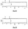
- FIGS. 3A and 3Bare respective waveforms of normalized RF voltage and current signals
- FIG. 4is a graph of an autocorrelation function of the RF voltage signal of FIG. 3A ;
- FIG. 5is a graph of an autocorrelation function of the RF current signal of FIG. 3B ;
- FIG. 6is a graph of cross correlation of the RF voltage and current signals of FIGS. 3A and 3B ;
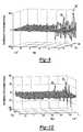
- FIG. 9is a graph of a first difference of the autocorrelation function for the voltage signal of FIG. 3A ;
- FIG. 10is a graph of a first difference of the autocorrelation function for the current signal of FIG. 3B
- FIG. 11is a graph of normalized output for cross correlation of the voltage and current signals
- FIGS. 12A and 12Bare respective waveforms of a normalized voltage signal and normalized current signal of an arc having brief duration when compared to a sample interval;
- FIG. 14is a Markov chain describing the arc process.
- modulerefers to an Application Specific Integrated Circuit (ASIC), an electronic circuit, a processor (shared, dedicated, or group) and memory that execute one or more software or firmware programs, a combinational logic circuit, and/or other suitable components that provide the described functionality.
- ASICApplication Specific Integrated Circuit
- processorshared, dedicated, or group
- memorythat execute one or more software or firmware programs, a combinational logic circuit, and/or other suitable components that provide the described functionality.
- RF plasma generator system 10includes an RF generator 12 that generates RF power for a plasma chamber 18 .
- An RF sensor 16generates first and second signals that represent respective electrical properties of the RF power.
- RF sensor 16may be implemented with a voltage/current (V/I) sensor or a directional coupler. When RF sensor 16 is implemented with the V/I sensor the first and second signals represent voltage and current of the RF power, respectively. When the RF sensor 16 is implemented with the directional coupler the first and second signals represent forward and reverse power of the RF power, respectively.
- V/Ivoltage/current
- the first and second signalsrepresent forward and reverse power of the RF power, respectively.
- An impedance matching network 14matches an output impedance of RF generator 12 to an input impedance of plasma chamber 18 .
- Impedance matching network 14is shown connected downstream of RF sensor 16 , however it should be appreciated that it may also be connected upstream of RF sensor 16 , i.e. between the RF sensor 16 and plasma chamber 18 .
- An analog to digital (A/D) module 20converts the first and second signals from RF sensor 16 to respective digital signals.
- the digital signalsare communicated to an analysis module 22 .
- Analysis module 22employs a correlation function to detect arcs in plasma chamber 18 based on the first and second signals. The arc detection method is described below in more detail.
- Analysis module 22generates an arc detect signal based on an outcome of the arc detect method.
- the arc detect signalis communicated to a control module 24 and a probabilistic module 36 and indicates whether an arc is occurring in plasma chamber 18 .
- Control module 24generates control signals 26 that control the RF power output of RF generator 12 .
- Control module 24also receives the arc detect signal and the data from the first and second signals via analysis module 22 .
- Control module 24generates an output based on the data and the arc detect signal. The output controls RF generator 12 such that the plasma is generated as desired and any arc detected in the plasma is extinguished in response to the arc detect signal.
- RF generator 12 and/or control module 24generates an enable signal 28 and communicates it to analysis module 22 .
- Enable signal 28is employed when RF generator 12 initiates plasma in plasma chamber 18 . While the plasma is initiating, the voltage and current of the RF power fluctuate. Enable signal 28 holds off or disables analysis module 22 such as to prevent it from misinterpreting the fluctuations as arcs.
- analysis module 22may detect whether the plasma is initiating and obviate a need for enable signal 28 . Analysis module 22 may determine whether plasma is initiating by monitoring the voltage and current of the RF power. When the voltage and current transition from zero to non-zero, then analysis module 22 may hold off generating the arc detect signal until after the voltage and current stabilize at non-zero values.
- a probabilistic module 36may be employed to process the arc detect signal in accordance with a method that is described below.
- Probabilistic module 36uses the arc detect signal to compute a probabilistic model and to predict a probability of an arc event.
- the modelis computed using a Baum-Welch algorithm and the probability of an arc event is computed using a Viterbi algorithm.
- Probabilistic module 36may be an off-line process that generates the model after data is collected.
- the resulting probabilistic modelbecomes a quantitative indicator that determines whether variations to process parameters associated with the semiconductor manufacturing process yield a decreased likelihood of arcs of various durations.
- Analysis module 22includes a subtraction module 30 , a window module 32 , and a correlation module 34 .
- Subtraction module 30subtracts a DC offset from the digital signals that are generated by A/D module 20 .
- Window module 32applies a window function to the digital data from subtraction module 30 .
- Correlation module 34cross correlates the windowed data in accordance with a method that is described below.
- correlation module 34Operation of correlation module 34 will now be described in more detail.
- the wideband, high speed digital data from A/D module 20provides valuable information of the spectral content of the RF power present on the RF transmission line between RF generator 12 and plasma chamber 18 .
- Spatial information contained in these signalsrepresents transitory behavior of systems connected to the RF transmission line.
- Arc detectioncan be achieved by coupling the spatial information with computation of a correlation function within correlation module 34 .
- Probabilistic module 36implements a probabilistic framework to bolster arc detection and provide a quantitative measure to demonstrate process improvement by the reduction of the likelihood of an arc event.
- Arc eventscan be characterized by rapid and abrupt transients that result from a discharge between the RF generated plasma and an electrode of plasma chamber 18 .
- the arc eventsmay damage devices being fabricated during a semiconductor manufacturing process.
- Other arc eventsare characterized by a discharge from the plasma to a sidewall of plasma chamber 18 and/or discharges within the plasma occurring from the build-up of polymer structures within the plasma.
- the polymerization of negative ionsmay also be referred to as dust particles.
- a sheath of the plasma for continuously powered plasmaretains negative ions. After a period of time, these negative ions build up and polymerize to form contaminating particles.
- the transient resulting from the dischargecauses perturbations on the electromagnetic signals represented by the information from A/D module 20 .
- Correlation module 34implements a discrete-time auto correlation function
- nis an index of the digital sample
- ⁇is a lag or delay in the function.
- Two additional properties of Eq. (1)are leveraged for the purpose of arc detection.
- the first propertyis that Eq. (1) contains a measure of the rate of change of the voltage and current.
- the second propertyis the function is periodic if the voltage and current signals contain periodic components.
- the correlationis performed on a windowed version of the digital signal containing N discrete time samples comprising M periods of the fundamental RF signal. Window module 32 applies the windowing function to the digital samples.
- the frequency of the RF poweris referred to as the fundamental signal.
- the fundamental signalis selected as the lowest frequency in the lowest frequency band of operation.
- the procedure to compute a spectral estimation of the signalcommences with subtraction module 30 subtracting a mean ⁇ x from the discrete-time signal x from A/D module 20 .
- x _ ⁇ [ n ]x ⁇ [ n ] - ⁇ x ⁇ ⁇ n ( 3 )
- the autocorrelation function for xis derived from r a [T] and scaled element by element of the autocorrelation function for the window function r w [T].
- FIGS. 3A and 3Bplots of normalized samples acquired at a rate of 100 MSPS are shown.
- FIG. 3Ashows a voltage envelope 50 and
- FIG. 3Bshows current envelope 60 .
- An arc eventoccurs at approximately 150 ⁇ S, which is indicated at arrow 52 and ends approximately 23 ⁇ S later as indicated at arrow 54 .
- the transient behavioris detectable in the voltage and current signals.
- the autocorrelation functionis computed for the voltage and currents signals using a Hanning window of length N.
- the autocorrelation for the voltage signalis shown in FIG. 4 .
- FIG. 5shows the autocorrelation function for the current signal. Since the voltage and current signals contains the periodic component for the fundamental frequency (13.56 MHz in this case, however it should be appreciated that other frequencies may be used) the corresponding correlation functions are also periodic. Lags of ⁇ also indicate periodic harmonic components emitted from the plasma.
- the autocorrelation functionsproduce an abrupt change that coincides with the initial appearance of the arc event.
- FIG. 6shows cross correlation function r vi [T]; also produces a periodic function with a visually detectable arc event.
- the arc detection methodshould be invariant to different plasma load impedance and power levels.
- the cross correlation function of the voltage and current signalsprovides immunity to a broader range of signals over an entire Smith Chart.
- the arc eventis apparent between times 52 and 56 (see FIG. 6 ) and detectable from the cross correlation function.
- Nextis a description of how the function can be used for an arc event detector.
- Analysis module 22should keep false positive arc detections to a minimum.
- analysis module 22includes probabilistic module 36 .
- Probabilistic module 36implements a probabilistic framework that assigns likelihood to the number of arc events detected. False positive could be attributed to normally occurring transients and instabilities arising from a change in power levels or even more abrupt, the ignition of the plasma.
- the solution to the latteris employ enable signal 28 to engage arc detection when the plasma is in a steady state. This is important in applications like pulsing, where the plasma state following transition periods could otherwise be mistakenly detected as an arc event.
- Correlation module 34implements a first difference of the correlation function with respect to the j th correlation function, r vi j -r vi j-1 .
- first difference of the autocorrelation functions for the voltage ( FIG. 9 ) and current signals ( FIG. 10 )prominent ridges are detectable for instances in time to detect the commencement and extinguishment of the arc event.
- FIG. 11shows a plot of the normalized output for the cross correlation of the voltage and current. In this plot, the duration of the arc even is palpable with the duration time indicated.
- FIGS. 12A and 12Bshow voltage envelope 50 and FIG. 12B shows current envelope 60 .
- the arcis shown as descending spike at 70 .
- the arc detection using the cross correlation function for voltage and currentis shown at FIG. 13 .
- a first-order Markov chainis shown that describes the probabilistic framework for a procedure to analyze the transitions of an arc event.
- a trellisis created that spans a duration. The duration could equate to the length of time for a process step, the entire process, or greater.
- the Markov chainincludes three states: no arc (S 0 ), arc event detected (S 1 ), and arc event occurring (S 2 ). Probabilities are also presented to describe the transition probabilities P mn from state m to state n. From the two examples used to describe our approach, we can ascertain how this model reflects the detection of varying durations of arcs. In the first example of FIGS. 3A and 3B the arc event lasted approximately 23 uS. For that case, the Markov chain would start at state S 0 and transition to S 1 when the arc event was detected at time 52 . Since that example had an arc event that remained active, the transition from S 1 to S 2 would be indicative of this scenario.
- the eloquence of using this frameworkis it provides the capability to determine the likelihood of an arc event from which the system engineer can use this information to adjust the process parameters and quantitatively determine the resulting improvement.
- the decoding of this sequence, using observations from the arc detector,is accomplished by using the Viterbi algorithm. This algorithm produces the probability of the observed sequence from
- the state transition probabilitiescan also be computed. As adjustments are made and the process is run, the observable information is collected. Using this information with a post-process algorithm, the transition probabilities can be computed and compared to the state transition probabilities prior to the adjustments. These probabilities are computed using an expectation maximization algorithm.
- the expectation maximization algorithmis an iterative algorithm used to maximize the model parameters based on the observed data. There are two steps to the expectation maximization algorithm. In the first step, the probabilities are marginalized given the current model. For the first iteration, initial conditions are applied to the model. During the second iteration the model parameters are optimized. This procedure iterates over these two steps until convergence of the model parameters is achieved. The procedure is described by the pseudo-code of Table 1.
- analysis module 22may be implemented in the analog domain.
- A/D module 20may be eliminated (see FIG. 1 ) and analysis module 22 receives analog first and second signals from RF sensor 16 .
- subtraction module 30 , window module 32 , the window function, and correlation module 34are also implemented in the analog domain.
Landscapes
- Physics & Mathematics (AREA)
- Engineering & Computer Science (AREA)
- Plasma & Fusion (AREA)
- Chemical & Material Sciences (AREA)
- Analytical Chemistry (AREA)
- Plasma Technology (AREA)
- Drying Of Semiconductors (AREA)
Abstract
Description
a[n]=w[n](x[n]−μx)∀n (4)
where w represents the vector of unobservable states in our model It should be appreciated that no limitation is placed on including other observable information such as RF and other process affecting parameters.
| TABLE 1 | |||
| 1.) | Initialize model parameters and obtain | ||
| 2.) | Until Convergence | ||
| a. | Compute the estimated transition | ||
| probabilities α(j) | |||
| b. | Compute the estimated state probabilities | ||
| β(j) | |||
| c. | Update α(j+1) := α(j) | ||
| d. | Update β (j+1) := β (j) | ||
| 3.) | End | ||
Claims (25)
Priority Applications (12)
| Application Number | Priority Date | Filing Date | Title |
|---|---|---|---|
| US12/031,171US8264237B2 (en) | 2008-02-14 | 2008-02-14 | Application of wideband sampling for arc detection with a probabilistic model for quantitatively measuring arc events |
| US12/175,867US8289029B2 (en) | 2008-02-14 | 2008-07-18 | Application of wideband sampling for arc detection with a probabilistic model for quantitatively measuring arc events |
| PCT/US2008/083347WO2009102358A1 (en) | 2008-02-14 | 2008-11-13 | Application of wideband sampling for arc detection with a probabilistic model for quantitatively measuring arc events |
| JP2010546746AJP5583603B2 (en) | 2008-02-14 | 2008-11-13 | Arc detection system and method |
| GB1009777.2AGB2468430B (en) | 2008-02-14 | 2008-11-13 | Application of wideband sampling for arc detection with a probabilistic model for quantitatively measuring arc events |
| DE112008003705.1TDE112008003705B4 (en) | 2008-02-14 | 2008-11-13 | Applying broadband scanning to arc detection with a probabilistic model to quantitatively measure arc events |
| KR1020107013838AKR101430165B1 (en) | 2008-02-14 | 2008-11-13 | Application of wideband sampling for arc detection with a probabilistic model for quantitatively measuring arc events |
| GB1219888.3AGB2493122B (en) | 2008-02-14 | 2008-11-13 | Application of wideband sampling for arc detection with a probabilistic model for quantitatively measuring arc events |
| CN2008801144154ACN101843178B (en) | 2008-02-14 | 2008-11-13 | Broadband Sampling Applications for Arc Detection Using Probabilistic Models for Quantitative Measurement of Arc Events |
| TW097146458ATWI496513B (en) | 2008-02-14 | 2008-11-28 | Arc detecting device for plasma generating system and detecting method thereof |
| US12/727,715US8334700B2 (en) | 2008-02-14 | 2010-03-19 | Arc detection |
| US13/648,317US8581597B2 (en) | 2008-02-14 | 2012-10-10 | Application of wideband sampling for arc detection with a probabilistic model for quantitatively measuring arc events |
Applications Claiming Priority (1)
| Application Number | Priority Date | Filing Date | Title |
|---|---|---|---|
| US12/031,171US8264237B2 (en) | 2008-02-14 | 2008-02-14 | Application of wideband sampling for arc detection with a probabilistic model for quantitatively measuring arc events |
Related Child Applications (1)
| Application Number | Title | Priority Date | Filing Date |
|---|---|---|---|
| US12/175,867Continuation-In-PartUS8289029B2 (en) | 2008-02-14 | 2008-07-18 | Application of wideband sampling for arc detection with a probabilistic model for quantitatively measuring arc events |
Publications (2)
| Publication Number | Publication Date |
|---|---|
| US20090206822A1 US20090206822A1 (en) | 2009-08-20 |
| US8264237B2true US8264237B2 (en) | 2012-09-11 |
Family
ID=40954508
Family Applications (1)
| Application Number | Title | Priority Date | Filing Date |
|---|---|---|---|
| US12/031,171Active2029-11-05US8264237B2 (en) | 2008-02-14 | 2008-02-14 | Application of wideband sampling for arc detection with a probabilistic model for quantitatively measuring arc events |
Country Status (1)
| Country | Link |
|---|---|
| US (1) | US8264237B2 (en) |
Cited By (6)
| Publication number | Priority date | Publication date | Assignee | Title |
|---|---|---|---|---|
| US20110057662A1 (en)* | 2008-04-21 | 2011-03-10 | Thomas Eriksson | Arc Detector And Associated Method For Detecting Undesired Arcs |
| US9147555B2 (en) | 2010-07-20 | 2015-09-29 | Trumpf Huettinger Gmbh + Co. Kg | Arc extinction arrangement and method for extinguishing arcs |
| US20170287684A1 (en)* | 2014-12-19 | 2017-10-05 | Trumpf Huettinger Sp. Z O. O. | Detecting an arc occuring during supplying power to a plasma process |
| EP3792955A1 (en) | 2019-09-10 | 2021-03-17 | Comet AG | Rf power generator with analogue and digital detectors |
| US11536755B2 (en) | 2020-05-29 | 2022-12-27 | Mks Instruments, Inc. | System and method for arc detection using a bias RF generator signal |
| US12148601B2 (en) | 2019-09-23 | 2024-11-19 | Trumpf Huettinger Sp. Z O. O. | Method of plasma processing a substrate in a plasma chamber and plasma processing system |
Families Citing this family (3)
| Publication number | Priority date | Publication date | Assignee | Title |
|---|---|---|---|---|
| US8044594B2 (en)* | 2008-07-31 | 2011-10-25 | Advanced Energy Industries, Inc. | Power supply ignition system and method |
| JP7417963B2 (en) | 2020-08-26 | 2024-01-19 | パナソニックIpマネジメント株式会社 | Arc detection device, arc detection system, arc detection method, and program |
| CN116371164A (en)* | 2023-05-12 | 2023-07-04 | 安徽臻环生态科技有限公司 | Low-temperature plasma waste gas treatment system and method |
Citations (24)
| Publication number | Priority date | Publication date | Assignee | Title |
|---|---|---|---|---|
| US3020529A (en) | 1959-12-21 | 1962-02-06 | Collins Radio Co | Reflected power alarm for a variable power output antenna system |
| US3519927A (en) | 1968-09-05 | 1970-07-07 | Us Air Force | Scanning analyzer for determining characteristics of an ionized plasma |
| US4588952A (en) | 1982-12-16 | 1986-05-13 | Japan Atomic Energy Research Institute | Arc discharge abnormality detecting system |
| JPH0831806A (en) | 1994-07-20 | 1996-02-02 | Hitachi Ltd | Plasma processing device |
| JPH08277468A (en) | 1995-04-04 | 1996-10-22 | Ulvac Japan Ltd | Dc power source of vacuum device |
| US5810963A (en) | 1995-09-28 | 1998-09-22 | Kabushiki Kaisha Toshiba | Plasma processing apparatus and method |
| US6124758A (en) | 1998-08-19 | 2000-09-26 | Harris Corporation | RF power amplifier control system |
| US20030046013A1 (en)* | 1998-02-27 | 2003-03-06 | Gerrish Kevin S. | Voltage current sensor with high matching directivity |
| US20030063420A1 (en) | 2001-09-28 | 2003-04-03 | Eaton Corporation | Method and apparatus for detecting and suppressing a parallel ARC fault |
| US20030205460A1 (en)* | 2002-04-12 | 2003-11-06 | Buda Paul R. | Apparatus and method for arc detection |
| US6718272B1 (en) | 2000-11-01 | 2004-04-06 | Eni Technology Inc. | Fast transient protection for RF plasma generator |
| US6902646B2 (en) | 2003-08-14 | 2005-06-07 | Advanced Energy Industries, Inc. | Sensor array for measuring plasma characteristics in plasma processing environments |
| WO2005074661A2 (en) | 2004-02-02 | 2005-08-18 | Inficon, Inc. | Rf sensor clamp assembly |
| US6954077B2 (en) | 2002-01-31 | 2005-10-11 | Tokyo Electron Limited | Apparatus and method for improving microwave coupling to a resonant cavity |
| US20060025820A1 (en)* | 2004-07-27 | 2006-02-02 | The Cleveland Clinic Foundation | Integrated system and method for MRI-safe implantable devices |
| US20060049831A1 (en)* | 2004-09-04 | 2006-03-09 | Applied Materials, Inc. | Detection and suppression of electrical arcing |
| US20060252283A1 (en) | 2003-08-07 | 2006-11-09 | Hitachi Kokusai Electric Inc. | Substrate processing apparatus and sustrate processing method |
| US20060259259A1 (en) | 2005-05-02 | 2006-11-16 | Mks Instruments, Inc. | Versatile semiconductor manufacturing controller with statistically repeatable response times |
| US7199327B2 (en) | 2002-06-28 | 2007-04-03 | Tokyo Electron Limited | Method and system for arc suppression in a plasma processing system |
| JP2007149596A (en) | 2005-11-30 | 2007-06-14 | Daihen Corp | Arc detector of plasma treatment system |
| US7301286B2 (en) | 2001-10-22 | 2007-11-27 | Shibaura Mechatronics Corporation | Method of detecting an arc in a glow-discharge device and apparatus for controlling a high-frequency arc discharge |
| US7305311B2 (en) | 2005-04-22 | 2007-12-04 | Advanced Energy Industries, Inc. | Arc detection and handling in radio frequency power applications |
| US7570028B2 (en) | 2007-04-26 | 2009-08-04 | Advanced Energy Industries, Inc. | Method and apparatus for modifying interactions between an electrical generator and a nonlinear load |
| US7728602B2 (en)* | 2007-02-16 | 2010-06-01 | Mks Instruments, Inc. | Harmonic derived arc detector |
- 2008
- 2008-02-14USUS12/031,171patent/US8264237B2/enactiveActive
Patent Citations (28)
| Publication number | Priority date | Publication date | Assignee | Title |
|---|---|---|---|---|
| US3020529A (en) | 1959-12-21 | 1962-02-06 | Collins Radio Co | Reflected power alarm for a variable power output antenna system |
| US3519927A (en) | 1968-09-05 | 1970-07-07 | Us Air Force | Scanning analyzer for determining characteristics of an ionized plasma |
| US4588952A (en) | 1982-12-16 | 1986-05-13 | Japan Atomic Energy Research Institute | Arc discharge abnormality detecting system |
| JPH0831806A (en) | 1994-07-20 | 1996-02-02 | Hitachi Ltd | Plasma processing device |
| JPH08277468A (en) | 1995-04-04 | 1996-10-22 | Ulvac Japan Ltd | Dc power source of vacuum device |
| US5810963A (en) | 1995-09-28 | 1998-09-22 | Kabushiki Kaisha Toshiba | Plasma processing apparatus and method |
| US20030046013A1 (en)* | 1998-02-27 | 2003-03-06 | Gerrish Kevin S. | Voltage current sensor with high matching directivity |
| US6124758A (en) | 1998-08-19 | 2000-09-26 | Harris Corporation | RF power amplifier control system |
| US6718272B1 (en) | 2000-11-01 | 2004-04-06 | Eni Technology Inc. | Fast transient protection for RF plasma generator |
| US20030063420A1 (en) | 2001-09-28 | 2003-04-03 | Eaton Corporation | Method and apparatus for detecting and suppressing a parallel ARC fault |
| US7301286B2 (en) | 2001-10-22 | 2007-11-27 | Shibaura Mechatronics Corporation | Method of detecting an arc in a glow-discharge device and apparatus for controlling a high-frequency arc discharge |
| US6954077B2 (en) | 2002-01-31 | 2005-10-11 | Tokyo Electron Limited | Apparatus and method for improving microwave coupling to a resonant cavity |
| US20030205460A1 (en)* | 2002-04-12 | 2003-11-06 | Buda Paul R. | Apparatus and method for arc detection |
| US7199327B2 (en) | 2002-06-28 | 2007-04-03 | Tokyo Electron Limited | Method and system for arc suppression in a plasma processing system |
| US7767053B2 (en) | 2003-08-07 | 2010-08-03 | Hitachi Kokusai Electric Inc. | Substrate processing apparatus and substrate processing method |
| US20060252283A1 (en) | 2003-08-07 | 2006-11-09 | Hitachi Kokusai Electric Inc. | Substrate processing apparatus and sustrate processing method |
| US6902646B2 (en) | 2003-08-14 | 2005-06-07 | Advanced Energy Industries, Inc. | Sensor array for measuring plasma characteristics in plasma processing environments |
| WO2005074661A3 (en) | 2004-02-02 | 2005-10-20 | Inficon Inc | Rf sensor clamp assembly |
| WO2005074661A2 (en) | 2004-02-02 | 2005-08-18 | Inficon, Inc. | Rf sensor clamp assembly |
| US20060025820A1 (en)* | 2004-07-27 | 2006-02-02 | The Cleveland Clinic Foundation | Integrated system and method for MRI-safe implantable devices |
| US20060049831A1 (en)* | 2004-09-04 | 2006-03-09 | Applied Materials, Inc. | Detection and suppression of electrical arcing |
| US7292045B2 (en) | 2004-09-04 | 2007-11-06 | Applied Materials, Inc. | Detection and suppression of electrical arcing |
| US7514936B2 (en) | 2004-09-04 | 2009-04-07 | Applied Materials, Inc. | Detection and suppression of electrical arcing |
| US7305311B2 (en) | 2005-04-22 | 2007-12-04 | Advanced Energy Industries, Inc. | Arc detection and handling in radio frequency power applications |
| US20060259259A1 (en) | 2005-05-02 | 2006-11-16 | Mks Instruments, Inc. | Versatile semiconductor manufacturing controller with statistically repeatable response times |
| JP2007149596A (en) | 2005-11-30 | 2007-06-14 | Daihen Corp | Arc detector of plasma treatment system |
| US7728602B2 (en)* | 2007-02-16 | 2010-06-01 | Mks Instruments, Inc. | Harmonic derived arc detector |
| US7570028B2 (en) | 2007-04-26 | 2009-08-04 | Advanced Energy Industries, Inc. | Method and apparatus for modifying interactions between an electrical generator and a nonlinear load |
Non-Patent Citations (1)
| Title |
|---|
| International Search Report for International Patent Application No. PCT/US2008/083347 dated Jul. 2, 2009. |
Cited By (11)
| Publication number | Priority date | Publication date | Assignee | Title |
|---|---|---|---|---|
| US20110057662A1 (en)* | 2008-04-21 | 2011-03-10 | Thomas Eriksson | Arc Detector And Associated Method For Detecting Undesired Arcs |
| US8508233B2 (en)* | 2008-04-21 | 2013-08-13 | Abb Research Ltd. | Arc detector and associated method for detecting undesired arcs |
| US9147555B2 (en) | 2010-07-20 | 2015-09-29 | Trumpf Huettinger Gmbh + Co. Kg | Arc extinction arrangement and method for extinguishing arcs |
| US20170287684A1 (en)* | 2014-12-19 | 2017-10-05 | Trumpf Huettinger Sp. Z O. O. | Detecting an arc occuring during supplying power to a plasma process |
| US10431437B2 (en)* | 2014-12-19 | 2019-10-01 | Trumpf Huettinger Sp. Z O. O. | Detecting an arc occuring during supplying power to a plasma process |
| EP3792955A1 (en) | 2019-09-10 | 2021-03-17 | Comet AG | Rf power generator with analogue and digital detectors |
| EP3907753A1 (en) | 2019-09-10 | 2021-11-10 | Comet AG | Rf power generator with analogue and digital detectors and method of operating such a power geberator |
| US11705314B2 (en) | 2019-09-10 | 2023-07-18 | Comet Ag | RF power generator with analogue and digital detectors |
| US12424425B2 (en) | 2019-09-10 | 2025-09-23 | Comet Ag | RF power generator with analogue and digital detectors |
| US12148601B2 (en) | 2019-09-23 | 2024-11-19 | Trumpf Huettinger Sp. Z O. O. | Method of plasma processing a substrate in a plasma chamber and plasma processing system |
| US11536755B2 (en) | 2020-05-29 | 2022-12-27 | Mks Instruments, Inc. | System and method for arc detection using a bias RF generator signal |
Also Published As
| Publication number | Publication date |
|---|---|
| US20090206822A1 (en) | 2009-08-20 |
Similar Documents
| Publication | Publication Date | Title |
|---|---|---|
| US8289029B2 (en) | Application of wideband sampling for arc detection with a probabilistic model for quantitatively measuring arc events | |
| US8334700B2 (en) | Arc detection | |
| US8264237B2 (en) | Application of wideband sampling for arc detection with a probabilistic model for quantitatively measuring arc events | |
| US9745660B2 (en) | Method for controlling a plasma chamber | |
| EP3254295B1 (en) | Arc treatment device and method therefor | |
| TWI555447B (en) | System and methods of bimodal automatic power and frequency tuning of rf generators | |
| JP6622311B2 (en) | Method for detecting arc generated during power supply of plasma process and plasma power source | |
| US10008371B2 (en) | Determining a value of a variable on an RF transmission model | |
| KR102265231B1 (en) | Plasma processing apparatus | |
| CN105389289B (en) | System, method and apparatus for monitoring operation of a radio frequency generator using optical data | |
| CN103681194A (en) | Edge ramping | |
| KR20090007394A (en) | Control of Plasma Treatment Using Parameters Derived Through Use of Planar Ion Flux Probing Apparatus | |
| CN114446752A (en) | Detection method and detection device for electric arc of plasma processing chamber | |
| EP1854306B1 (en) | Tunable filter for tone detection | |
| KR20140098477A (en) | method for anticipating plasma micro arcing and plasma process management method of the production equipment used the same | |
| KR20150069549A (en) | Rf impedance model based fault detection | |
| WO2005098091A2 (en) | A method of plasma etch endpoint detection using a v-i probe diagnostics | |
| Koh et al. | Principal component analysis of plasma harmonics in end-point detection of photoresist stripping | |
| CN109243955B (en) | Plasma glow starting state monitoring method and monitoring device and semiconductor processing equipment | |
| KR102803167B1 (en) | Rf generator system and its operating method | |
| KR101162178B1 (en) | A Signal Process Method for improving S/N of Ion Cyclotron Resonance Mass Spectrometer | |
| JP2002033310A (en) | Plasma processing equipment | |
| KR20210148545A (en) | Arcing forecasting and monitoring system through ground vlotage monitoring of plasma process equipment | |
| CN118866736A (en) | Radio frequency power monitoring method, semiconductor process chamber and equipment |
Legal Events
| Date | Code | Title | Description |
|---|---|---|---|
| AS | Assignment | Owner name:MKS INSTRUMENTS, INC., MASSACHUSETTS Free format text:ASSIGNMENT OF ASSIGNORS INTEREST;ASSIGNOR:COUMOU, DAVID J.;REEL/FRAME:020689/0862 Effective date:20080304 | |
| STCF | Information on status: patent grant | Free format text:PATENTED CASE | |
| FPAY | Fee payment | Year of fee payment:4 | |
| AS | Assignment | Owner name:DEUTSCHE BANK AG NEW YORK BRANCH, NEW YORK Free format text:SECURITY AGREEMENT;ASSIGNORS:MKS INSTRUMENTS, INC.;NEWPORT CORPORATION;REEL/FRAME:038663/0265 Effective date:20160429 Owner name:BARCLAYS BANK PLC, NEW YORK Free format text:SECURITY AGREEMENT;ASSIGNORS:MKS INSTRUMENTS, INC.;NEWPORT CORPORATION;REEL/FRAME:038663/0139 Effective date:20160429 | |
| AS | Assignment | Owner name:BARCLAYS BANK PLC, AS COLLATERAL AGENT, NEW YORK Free format text:PATENT SECURITY AGREEMENT (ABL);ASSIGNORS:ELECTRO SCIENTIFIC INDUSTRIES, INC.;MKS INSTRUMENTS, INC.;NEWPORT CORPORATION;REEL/FRAME:048211/0312 Effective date:20190201 Owner name:MKS INSTRUMENTS, INC., MASSACHUSETTS Free format text:RELEASE BY SECURED PARTY;ASSIGNOR:DEUTSCHE BANK AG NEW YORK BRANCH;REEL/FRAME:048226/0095 Effective date:20190201 Owner name:NEWPORT CORPORATION, CALIFORNIA Free format text:RELEASE BY SECURED PARTY;ASSIGNOR:DEUTSCHE BANK AG NEW YORK BRANCH;REEL/FRAME:048226/0095 Effective date:20190201 | |
| MAFP | Maintenance fee payment | Free format text:PAYMENT OF MAINTENANCE FEE, 8TH YEAR, LARGE ENTITY (ORIGINAL EVENT CODE: M1552); ENTITY STATUS OF PATENT OWNER: LARGE ENTITY Year of fee payment:8 | |
| CC | Certificate of correction | ||
| AS | Assignment | Owner name:BARCLAYS BANK PLC, AS COLLATERAL AGENT, NEW YORK Free format text:CORRECTIVE ASSIGNMENT TO CORRECT THE REMOVE U.S. PATENT NO.7,919,646 PREVIOUSLY RECORDED ON REEL 048211 FRAME 0312. ASSIGNOR(S) HEREBY CONFIRMS THE PATENT SECURITY AGREEMENT (ABL);ASSIGNORS:ELECTRO SCIENTIFIC INDUSTRIES, INC.;MKS INSTRUMENTS, INC.;NEWPORT CORPORATION;REEL/FRAME:055668/0687 Effective date:20190201 | |
| AS | Assignment | Owner name:JPMORGAN CHASE BANK, N.A., AS COLLATERAL AGENT, ILLINOIS Free format text:SECURITY INTEREST;ASSIGNORS:MKS INSTRUMENTS, INC.;NEWPORT CORPORATION;ELECTRO SCIENTIFIC INDUSTRIES, INC.;REEL/FRAME:061572/0069 Effective date:20220817 | |
| AS | Assignment | Owner name:ELECTRO SCIENTIFIC INDUSTRIES, INC., OREGON Free format text:RELEASE BY SECURED PARTY;ASSIGNOR:BARCLAYS BANK PLC;REEL/FRAME:063009/0001 Effective date:20220817 Owner name:NEWPORT CORPORATION, MASSACHUSETTS Free format text:RELEASE BY SECURED PARTY;ASSIGNOR:BARCLAYS BANK PLC;REEL/FRAME:063009/0001 Effective date:20220817 Owner name:MKS INSTRUMENTS, INC., MASSACHUSETTS Free format text:RELEASE BY SECURED PARTY;ASSIGNOR:BARCLAYS BANK PLC;REEL/FRAME:063009/0001 Effective date:20220817 Owner name:ELECTRO SCIENTIFIC INDUSTRIES, INC., OREGON Free format text:RELEASE BY SECURED PARTY;ASSIGNOR:BARCLAYS BANK PLC;REEL/FRAME:062739/0001 Effective date:20220817 Owner name:NEWPORT CORPORATION, MASSACHUSETTS Free format text:RELEASE BY SECURED PARTY;ASSIGNOR:BARCLAYS BANK PLC;REEL/FRAME:062739/0001 Effective date:20220817 Owner name:MKS INSTRUMENTS, INC., MASSACHUSETTS Free format text:RELEASE BY SECURED PARTY;ASSIGNOR:BARCLAYS BANK PLC;REEL/FRAME:062739/0001 Effective date:20220817 | |
| MAFP | Maintenance fee payment | Free format text:PAYMENT OF MAINTENANCE FEE, 12TH YEAR, LARGE ENTITY (ORIGINAL EVENT CODE: M1553); ENTITY STATUS OF PATENT OWNER: LARGE ENTITY Year of fee payment:12 |