US8262720B2 - Prosthesis comprising dual tapered stent - Google Patents
Prosthesis comprising dual tapered stentDownload PDFInfo
- Publication number
- US8262720B2 US8262720B2US11/001,813US181304AUS8262720B2US 8262720 B2US8262720 B2US 8262720B2US 181304 AUS181304 AUS 181304AUS 8262720 B2US8262720 B2US 8262720B2
- Authority
- US
- United States
- Prior art keywords
- stent
- prosthesis
- diameter
- intermediate section
- graft material
- Prior art date
- Legal status (The legal status is an assumption and is not a legal conclusion. Google has not performed a legal analysis and makes no representation as to the accuracy of the status listed.)
- Expired - Fee Related, expires
Links
Images

Classifications
- A—HUMAN NECESSITIES
- A61—MEDICAL OR VETERINARY SCIENCE; HYGIENE
- A61F—FILTERS IMPLANTABLE INTO BLOOD VESSELS; PROSTHESES; DEVICES PROVIDING PATENCY TO, OR PREVENTING COLLAPSING OF, TUBULAR STRUCTURES OF THE BODY, e.g. STENTS; ORTHOPAEDIC, NURSING OR CONTRACEPTIVE DEVICES; FOMENTATION; TREATMENT OR PROTECTION OF EYES OR EARS; BANDAGES, DRESSINGS OR ABSORBENT PADS; FIRST-AID KITS
- A61F2/00—Filters implantable into blood vessels; Prostheses, i.e. artificial substitutes or replacements for parts of the body; Appliances for connecting them with the body; Devices providing patency to, or preventing collapsing of, tubular structures of the body, e.g. stents
- A61F2/02—Prostheses implantable into the body
- A61F2/04—Hollow or tubular parts of organs, e.g. bladders, tracheae, bronchi or bile ducts
- A61F2/06—Blood vessels
- A61F2/07—Stent-grafts
- A—HUMAN NECESSITIES
- A61—MEDICAL OR VETERINARY SCIENCE; HYGIENE
- A61F—FILTERS IMPLANTABLE INTO BLOOD VESSELS; PROSTHESES; DEVICES PROVIDING PATENCY TO, OR PREVENTING COLLAPSING OF, TUBULAR STRUCTURES OF THE BODY, e.g. STENTS; ORTHOPAEDIC, NURSING OR CONTRACEPTIVE DEVICES; FOMENTATION; TREATMENT OR PROTECTION OF EYES OR EARS; BANDAGES, DRESSINGS OR ABSORBENT PADS; FIRST-AID KITS
- A61F2/00—Filters implantable into blood vessels; Prostheses, i.e. artificial substitutes or replacements for parts of the body; Appliances for connecting them with the body; Devices providing patency to, or preventing collapsing of, tubular structures of the body, e.g. stents
- A61F2/82—Devices providing patency to, or preventing collapsing of, tubular structures of the body, e.g. stents
- A61F2/86—Stents in a form characterised by the wire-like elements; Stents in the form characterised by a net-like or mesh-like structure
- A61F2/90—Stents in a form characterised by the wire-like elements; Stents in the form characterised by a net-like or mesh-like structure characterised by a net-like or mesh-like structure
- A61F2/91—Stents in a form characterised by the wire-like elements; Stents in the form characterised by a net-like or mesh-like structure characterised by a net-like or mesh-like structure made from perforated sheets or tubes, e.g. perforated by laser cuts or etched holes
- A61F2/915—Stents in a form characterised by the wire-like elements; Stents in the form characterised by a net-like or mesh-like structure characterised by a net-like or mesh-like structure made from perforated sheets or tubes, e.g. perforated by laser cuts or etched holes with bands having a meander structure, adjacent bands being connected to each other
- A—HUMAN NECESSITIES
- A61—MEDICAL OR VETERINARY SCIENCE; HYGIENE
- A61F—FILTERS IMPLANTABLE INTO BLOOD VESSELS; PROSTHESES; DEVICES PROVIDING PATENCY TO, OR PREVENTING COLLAPSING OF, TUBULAR STRUCTURES OF THE BODY, e.g. STENTS; ORTHOPAEDIC, NURSING OR CONTRACEPTIVE DEVICES; FOMENTATION; TREATMENT OR PROTECTION OF EYES OR EARS; BANDAGES, DRESSINGS OR ABSORBENT PADS; FIRST-AID KITS
- A61F2/00—Filters implantable into blood vessels; Prostheses, i.e. artificial substitutes or replacements for parts of the body; Appliances for connecting them with the body; Devices providing patency to, or preventing collapsing of, tubular structures of the body, e.g. stents
- A61F2/02—Prostheses implantable into the body
- A61F2/04—Hollow or tubular parts of organs, e.g. bladders, tracheae, bronchi or bile ducts
- A61F2/06—Blood vessels
- A61F2002/065—Y-shaped blood vessels
- A61F2002/067—Y-shaped blood vessels modular
- A—HUMAN NECESSITIES
- A61—MEDICAL OR VETERINARY SCIENCE; HYGIENE
- A61F—FILTERS IMPLANTABLE INTO BLOOD VESSELS; PROSTHESES; DEVICES PROVIDING PATENCY TO, OR PREVENTING COLLAPSING OF, TUBULAR STRUCTURES OF THE BODY, e.g. STENTS; ORTHOPAEDIC, NURSING OR CONTRACEPTIVE DEVICES; FOMENTATION; TREATMENT OR PROTECTION OF EYES OR EARS; BANDAGES, DRESSINGS OR ABSORBENT PADS; FIRST-AID KITS
- A61F2/00—Filters implantable into blood vessels; Prostheses, i.e. artificial substitutes or replacements for parts of the body; Appliances for connecting them with the body; Devices providing patency to, or preventing collapsing of, tubular structures of the body, e.g. stents
- A61F2/02—Prostheses implantable into the body
- A61F2/04—Hollow or tubular parts of organs, e.g. bladders, tracheae, bronchi or bile ducts
- A61F2/06—Blood vessels
- A61F2/07—Stent-grafts
- A61F2002/075—Stent-grafts the stent being loosely attached to the graft material, e.g. by stitching
- A—HUMAN NECESSITIES
- A61—MEDICAL OR VETERINARY SCIENCE; HYGIENE
- A61F—FILTERS IMPLANTABLE INTO BLOOD VESSELS; PROSTHESES; DEVICES PROVIDING PATENCY TO, OR PREVENTING COLLAPSING OF, TUBULAR STRUCTURES OF THE BODY, e.g. STENTS; ORTHOPAEDIC, NURSING OR CONTRACEPTIVE DEVICES; FOMENTATION; TREATMENT OR PROTECTION OF EYES OR EARS; BANDAGES, DRESSINGS OR ABSORBENT PADS; FIRST-AID KITS
- A61F2230/00—Geometry of prostheses classified in groups A61F2/00 - A61F2/26 or A61F2/82 or A61F9/00 or A61F11/00 or subgroups thereof
- A61F2230/0002—Two-dimensional shapes, e.g. cross-sections
- A61F2230/0028—Shapes in the form of latin or greek characters
- A61F2230/0054—V-shaped
- A—HUMAN NECESSITIES
- A61—MEDICAL OR VETERINARY SCIENCE; HYGIENE
- A61F—FILTERS IMPLANTABLE INTO BLOOD VESSELS; PROSTHESES; DEVICES PROVIDING PATENCY TO, OR PREVENTING COLLAPSING OF, TUBULAR STRUCTURES OF THE BODY, e.g. STENTS; ORTHOPAEDIC, NURSING OR CONTRACEPTIVE DEVICES; FOMENTATION; TREATMENT OR PROTECTION OF EYES OR EARS; BANDAGES, DRESSINGS OR ABSORBENT PADS; FIRST-AID KITS
- A61F2250/00—Special features of prostheses classified in groups A61F2/00 - A61F2/26 or A61F2/82 or A61F9/00 or A61F11/00 or subgroups thereof
- A61F2250/0014—Special features of prostheses classified in groups A61F2/00 - A61F2/26 or A61F2/82 or A61F9/00 or A61F11/00 or subgroups thereof having different values of a given property or geometrical feature, e.g. mechanical property or material property, at different locations within the same prosthesis
- A61F2250/0018—Special features of prostheses classified in groups A61F2/00 - A61F2/26 or A61F2/82 or A61F9/00 or A61F11/00 or subgroups thereof having different values of a given property or geometrical feature, e.g. mechanical property or material property, at different locations within the same prosthesis differing in elasticity, stiffness or compressibility
- A—HUMAN NECESSITIES
- A61—MEDICAL OR VETERINARY SCIENCE; HYGIENE
- A61F—FILTERS IMPLANTABLE INTO BLOOD VESSELS; PROSTHESES; DEVICES PROVIDING PATENCY TO, OR PREVENTING COLLAPSING OF, TUBULAR STRUCTURES OF THE BODY, e.g. STENTS; ORTHOPAEDIC, NURSING OR CONTRACEPTIVE DEVICES; FOMENTATION; TREATMENT OR PROTECTION OF EYES OR EARS; BANDAGES, DRESSINGS OR ABSORBENT PADS; FIRST-AID KITS
- A61F2250/00—Special features of prostheses classified in groups A61F2/00 - A61F2/26 or A61F2/82 or A61F9/00 or A61F11/00 or subgroups thereof
- A61F2250/0014—Special features of prostheses classified in groups A61F2/00 - A61F2/26 or A61F2/82 or A61F9/00 or A61F11/00 or subgroups thereof having different values of a given property or geometrical feature, e.g. mechanical property or material property, at different locations within the same prosthesis
- A61F2250/0039—Special features of prostheses classified in groups A61F2/00 - A61F2/26 or A61F2/82 or A61F9/00 or A61F11/00 or subgroups thereof having different values of a given property or geometrical feature, e.g. mechanical property or material property, at different locations within the same prosthesis differing in diameter
Definitions
- the present inventionrelates to devices and methods for repairing aneurysms. More particularly, the present invention relates to a prosthesis comprising a dual tapered stent.
- An endoprosthesis or stent-graftis commonly used as a tubular structure left inside the lumen of a duct to relieve an obstruction.
- endoprosthesesare inserted into the lumen in a non-expanded form and are then expanded autonomously or with the aid of a second device in situ.
- the endoprosthesismay be self-expanding, or expansion may occur through the use of a catheter mounted angioplasty balloon, in order to shear and disrupt the obstructions associated with the wall components of the vessel and to obtain an enlarged lumen.
- restenosismay occur as a result of elastic recoil of the stenotic lesion.
- the endoprosthesisshould preferably be of a somewhat rigid design to provide reinforcement support and may be required to be of considerable length in order to extend over a lengthy diseased area. It is difficult to resolve this need for rigidity with the need of having a flexible endoprosthesis which is readily implanted by inserting it through a sometimes tortuous curving path as is often encountered in a percutaneous insertion technique typically used for implantation of endoprosthesis. This is further complicated by the fact that the endoprosthesis must be readily expandable upon implantation to provide support structure.
- stent designs for use in endoprostheseshave been reported, these designs have suffered from a number of limitations. These include restrictions on the dimensions and flexibility of the stent.
- a stent having rigid ends and a flexible median partis typically formed of multiple parts and is not continuously flexible along the longitudinal axis.
- Other stentsexist that are longitudinally flexible but consist of a plurality of cylindrical elements connected by flexible members.
- This designhas at least one important disadvantage. For example, according to this design, protruding edges occur when the stent is flexed around a curve raising the possibility of inadvertent retention of the stent on plaque deposited on arterial walls. This may cause the stent or plaque to embolize or move out of position and further cause damage to the interior lining of healthy vessels.
- the flexible prosthesis of the present inventionovercomes the limitations of the devices and methods as briefly described above.
- the present inventionis directed to a prosthesis comprising a stent having a first end and a second end with an intermediate section therebetween.
- the first and second endseach include an anchor, wherein at least one anchor has a diameter that is larger than the diameter of the intermediate section.
- the prosthesisalso comprises graft material engaging at least a portion of the stent.
- the stentis comprised of shape memory material and the intermediate section is flexible.
- the diameter of the first end and the diameter of the second end of the stentis preferably between about 15 mm and about 25 mm.
- the diameter of the intermediate section of the stentis preferably between about 8 mm and about 12 mm.
- the first end of the stentis configured to attach to another device within a lumen such as a prosthesis, stent, or stent gasket, and the second end of the stent is configured to be anchored within the interior wall of a lumen.
- the prosthesiscomprises a stent having a first end and a second end with an intermediate section disposed therebetween.
- the first end and the second endeach include a means for sealing the respective end to a structure.
- the first and/or second endeach has a diameter that is larger than the diameter of the intermediate section.
- the prosthesisalso comprises graft material engaging at least a portion of the stent.
- the first end of the stentis configured to form a seal with another device within a lumen, such as a prosthesis, stent, or stent gasket, and the second end is configured to form a seal with the interior wall of the lumen.
- the present inventionis also related to a method for repairing an abdominal aortic aneurysm comprising delivering a prosthesis within an interior wall of a lumen.
- the prosthesiscomprises a stent having a first end and a second end with an intermediate section therebetween.
- the first and/or second ends of the stenteach have a diameter larger than the diameter of the intermediate section of the stent.
- the prosthesisalso comprises graft material engaging at least a portion of the stent.
- the stentis comprised of shape memory material. Furthermore, the first end of the stent is attached to another device within the lumen, and the second end of the stent is anchored within the interior wall of the lumen.
- the prosthesismay provide a conduit for fluid flow to the iliac artery.
- FIGUREshows an illustrative embodiment of the invention from which these and other of the objectives, novel features and advantages will be readily apparent.
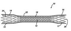
- FIG. 1is a side view of a prosthesis in accordance with the present invention.
- aortic aneurysmrefers to any failure of a conduit, such as an aortic wall, typically characterized by an undesirable dilation of a portion of the artery, vessel malformation, or an occlusion.
- the methods and structures of the present inventionmay be used to treat, repair, replace, or bypass any blood vessel (e.g., artery, vein, capillary); any fluid carrying vessel (e.g., lymphatic vessels); any organ or portion thereof that includes a blood or fluid vessel; or any junction between blood vessels, between fluid vessels, and between organs and blood vessels.
- An exemplary use of methods and structures of the present inventionis to repair an aortic aneurysm, and the use of such term is not intended to limit the use of the methods or structures of the present invention to repair or replace other conduit failures.
- the structures and methods of the present inventionmay also be utilized in the thoracic aorta, and may be used to repair thoracic aneurysms or thoracic dissecting aneurysms. Accordingly, use of the term “aortic aneurysm” is intended to relate to and include other aneurysms, including but not limited to both abdominal aortic aneurysms and thoracic aneurysms.
- fluid pathwayrefers to any in vivo structure through which a biological fluid passes.
- a preferred fluid pathwayis an artery.
- Fluid pathwaysinclude, but are not limited to channels formed by an artery a vein, a capillary, lymph nodes and channels, and arteries, veins, and capillaries within an organ or organelle.
- fluid or biological fluidrefers to any fluid produced by an animal, including a human.
- exemplary biological fluidsinclude, but are not limited to blood, oxygenated blood, de-oxygenated blood, gastric fluids, amniotic fluid, spinal fluid, and lymph.
- the preferred fluidis blood or oxygenated blood.
- adapted for communication, communicating, or similar termsrefer to any means, structures, or methods for establishing operational association between two elements of the system.
- engaging, adapted to engage, or similar termsrefer to means, structures, or methods for contacting a first component, structure, or portion thereof with a second component, structure, or portion thereof.
- Exemplary structuresare shown in the Figure.
- all of these terms and phrasesrefer to at least one structure in or on a first component configured to engage a complementary structure in or on a second component, and the use of these inter-engaging features to link a first component with a second component.
- the engagement or communicationmay be matingly for example, permanent and/or releasably, for example, temporary.
- communication or engagementmay be fluid tight, substantially fluid tight, or fluid tight to an extent so as to not substantially compromise the intended function of the structure.
- a connectormay be adapted to receive or connect to a complementary connector on another graft or prosthesis.
- connectorrefers to any structure used to form a joint or to join itself to another component or portion thereof.
- These connectors or connectionsestablish a fluid flow path through various elements of the apparatus, assembly, or system.
- the methods or structuresare intended to establish at least one fluid flow path through a vessel, conduit, organ, or portions thereof.
- Typical connectionsinclude but are not limited to mating connections, such as Luer-type, screw-type, friction-type, or connectors that are bonded together.
- distalis used in accordance with its ordinary dictionary definition, i.e., referring to a position farthest from the beginning; in human anatomy, this term is commonly equivalent to caudal or inferior.
- Proximalis used in accordance with its ordinary dictionary definition, i.e., referring to a position nearest the beginning; in human anatomy, this term is commonly equivalent to cranial or superior.
- distal and proximalare intended to convey opposite ends or portions of a device, channel, element, or structure.
- distalwill typically refer to a downstream location in the fluid flow path, and proximal will typically refer to an upstream location, unless otherwise specifically noted.
- the apparatuses and methods of the present inventionmay be used in the treatment of aortic aneurysms, preferably an abdominal aortic aneurysm, among other uses noted below.
- aortic aneurysmspreferably an abdominal aortic aneurysm
- a better understanding of the present device and its use in treating aortic aneurysmswill be achieved by reading the following description in conjunction with the following incorporated references.
- a prosthesis 10comprising a stent 12 defining an interior space or lumen having an open first end 14 comprising an anchor 15 , and an open second end 16 comprising an anchor 17 , with an intermediate section 18 therebetween.
- the diameter of the first end 14 and the diameter of the second end 16 of the stent 12are larger than the diameter of the intermediate section 18 .
- only one of the two endsmay have a larger diameter.
- the diameter of the first end 14 and the diameter of the second end 16are each between about 15 mm and about 25 mm.
- the diameter of the intermediate section 18 of the stent 12is preferably between about 8 mm and about 12 mm.
- the stent 12may be comprised of any material suitable for functioning in vivo and which allows for a variation in diameter along the length of the stent.
- the stent 12is comprised of shape memory material.
- the shape memory materialmay be comprised of various materials including, but not limited to shape memory metals or metal alloys.
- the shape memory materialis comprised of a Nickel Titanium alloy (Nitinol).
- the stent material and prosthesis 10are expandable or collapsible, i.e., moveable from a first closed position to a second open position, or vice versa.
- the stent 12 and prosthesis 10 of the present inventionmay also be self-expandable.
- the stent 12may comprise an expandable lattice or network of interconnected struts.
- the latticeis fabricated, e.g., laser cut, from an integral tube of material. It is preferred that the stent 12 structure be continuous and extend the full length of the stent, rather than consist of a series of individual support structures attached via sutures or some other mechanism to graft material. It is also preferred that the intermediate section 18 of the stent 12 be comprised of periodically joined, substantially zig-zag shaped struts in order to increase flexibility of the intermediate section.
- the first end 14 and the second end 16 of the stent 12are each preferably comprised of substantially diamond shaped struts to increase radial strength and anchor stability of the ends.
- the design of the stent 12 and prosthesis 10 of the present inventioncombines the necessity of large diameter ends 14 and 16 for anchoring and/or sealing means within a lumen, with the advantage of a reduced diameter body or intermediate section 18 .
- the first and second ends 14 and 16 of the stent 12may be strong and stiff to provide a sufficient anchor and seal within a lumen.
- the intermediate section 18 of the stent 12has a reduced diameter which provides strength and flexibility to the stent and prosthesis 10 , allowing them to be contoured with ease and conform to accommodate varying anatomy.
- the intermediate section 18 of the stentprovides an uncompromised conduit for flow within a lumen without kinking.
- the stent 12 of the present inventionforms a support or lattice structure suitable for supporting a graft material 22 .
- the stent 12 of the present inventionmaintains lumen patency in the prosthesis 10 while maintaining flexibility and kink resistance by using a design having two ends 14 and 16 which taper to a reduced diameter body or intermediate section 18 .
- the stent 12defines a channel through which a fluid, such as blood, may flow.
- the prosthesis 10 of the present inventionmay be used to repair an abdominal aortic aneurysm by delivering the prosthesis within the interior wall of a lumen.
- the stent 12including the first end 14 , second end 16 and intermediate section 18 , is preferably covered with a continuous graft material 22 which also varies in diameter along its length, whereby the ends of the graft material have a larger diameter than the intermediate section of the graft material, as illustrated in FIG. 1 .
- the stent 12may be designed to match the diameter of the expanded graft material 22 . Alternately, the stent 12 may be designed to be larger than the expanded graft material 22 , in which case the graft material 22 will constrain the stent 12 and dictate the diameter of the stent 12 and prosthesis 10 .
- the graft material 22may be made from any number of materials known to those having skill in the art, including but not limited to woven polyester, Dacron®, Teflon®, polyurethane, porous polyurethane, silicon, polyethylene terephthlate, expaned polytetrafluoroethylene (ePTFE) and blends of various materials.
- a biodegradable, or degradable materialsuch as albumin, or a collagen.
- a graft material 22 that is biodegradablewould erode or dissolve over time; however it is believed that a layer of endothelium may grow as the graft material erodes. It is further believed that these new layers of endothelium may provide a new, fluid impervious lining within the aneurysm.
- all of the foregoing materialsbe porous to allow for an intimal layer to form a biofusion structure or matrix.
- the graft material 22may be variously configured, preferably to achieve predetermined mechanical properties.
- the graft material 22may incorporate a single or multiple weaving and/or pleating patterns, or may be pleated or unpleated.
- the graft 22may be configured into a plain weave, a satin weave, include longitudinal pleats, interrupted pleats, annular or helical pleats, radially oriented pleats, or combinations thereof.
- the graft material 22may be knitted or braided.
- the pleatsmay be continuous or discontinuous.
- the pleatsmay be oriented longitudinally, circumferentially, or combinations thereof.
- the graft material 22may be impervious or substantially impervious to the flow of blood, or may be porous.
- a graft material 22is impervious if it prevents blood from passing through the graft material on contact with blood or after the graft material is saturated with blood.
- Choice of the flow characteristics of a graft material 22are well known to those skilled in the art, and are tied in part to the intended function of the prosthesis 10 or portion of the prosthesis.
- the foregoing graft material 22may be knitted or woven, and may be warp or weft knitted. If the graft material 22 is warp knitted, it may be provided with a velour, or towel like surface; which is believed to speed the formation of blood clots, thereby promoting the integration of a prosthesis 10 or prosthesis component into the surrounding cellular structure.
- a graft material 22that limits or eliminates the amount of blood that passes between the graft material and the arterial wall, to provide a catheter-delivered graft or prosthesis 10 that extends through a longer portion of an artery, to improve the anchoring and/or mechanisms between two prostheses, to improve the anchoring and/or sealing mechanism between the prosthesis 10 and the arterial wall or an interluminal cavity within an artery, and to improve the fluid dynamic and performance characteristics of the implanted prosthesis.
- the stent 12may be attached to the graft material 22 by any number of attachment means or methods known to those skilled in the art, including friction (if placed inside the graft); adhesives, such as polyurethane glue; a plurality of conventional sutures of polyvinylidene fluoride, polypropylene, Dacron®, or any other suitable material; ultrasonic welding; mechanical interference fit; loops; folds; sutures; and staples.
- the stent 12may also comprise attachment members 24 . These attachment members 24 may be positioned at various locations around the stent 12 so that staples or sutures may be easily attached to the stent 12 for securing the graft material 22 thereto. These attachment members 24 would contain holes or eyelets for the staples or suturer.
- the attachment members 24may also serve a dual purpose. In addition to connection points, the members 24 may also serve as radiopaque markers for facilitating prosthesis 10 placement. Alternately, they may just serve as markers.
- the stent 12may be attached to the interior suface or exterior surface of the graft material 22 by any of the attachment means or methods described above.
- the first end 14 of the stent 12is typically the proximal or cranial end of the stent, and the second end 16 of the stent is typically the caudal or distal end.
- the first end 14 and second end 16 of the stent 12may each be anchored within a lumen by anchoring the respective end directly to the interior wall of the lumen, or by attaching the first end 14 and/or second end 16 to another device within the lumen, such as to another stent, prosthesis or stent gasket.
- the cranial end 14 of the stent 12is attached to and anchored within a stent gasket, or other prosthesis and the caudal end 16 is anchored directly to the interior wall of a lumen.
- the caudal end 16 of the stent 12may be anchored within an iliac artery, for example, wherein the prosthesis 10 provides a closed conduit for blood flow from the stent gasket to the iliac artery.
- the first end 14 and second end 16when expanded, may each form a seal to a structure, e.g., to another stent, to a prosthesis, to a stent gasket, or to the interior wall of a lumen such as an iliac artery, as described above.
- the stent 12may also comprise one or more recapture legs 26 that extend from at least one of the two ends.
- the recapture legs 26may comprise any suitable design that allows for the deployment device to recapture the deployed stent 12 .
Landscapes
- Health & Medical Sciences (AREA)
- Gastroenterology & Hepatology (AREA)
- Pulmonology (AREA)
- Cardiology (AREA)
- Oral & Maxillofacial Surgery (AREA)
- Transplantation (AREA)
- Engineering & Computer Science (AREA)
- Biomedical Technology (AREA)
- Heart & Thoracic Surgery (AREA)
- Vascular Medicine (AREA)
- Life Sciences & Earth Sciences (AREA)
- Animal Behavior & Ethology (AREA)
- General Health & Medical Sciences (AREA)
- Public Health (AREA)
- Veterinary Medicine (AREA)
- Prostheses (AREA)
- Media Introduction/Drainage Providing Device (AREA)
Abstract
Description
Claims (6)
Priority Applications (4)
| Application Number | Priority Date | Filing Date | Title |
|---|---|---|---|
| US11/001,813US8262720B2 (en) | 2004-12-02 | 2004-12-02 | Prosthesis comprising dual tapered stent |
| EP05257247AEP1666003A1 (en) | 2004-12-02 | 2005-11-24 | Prosthesis comprising a stent with a tapered central portion |
| JP2005348226AJP5197919B2 (en) | 2004-12-02 | 2005-12-01 | Prosthetic device including double tapered stent |
| CA2528717ACA2528717C (en) | 2004-12-02 | 2005-12-01 | Prosthesis comprising dual tapered stent |
Applications Claiming Priority (1)
| Application Number | Priority Date | Filing Date | Title |
|---|---|---|---|
| US11/001,813US8262720B2 (en) | 2004-12-02 | 2004-12-02 | Prosthesis comprising dual tapered stent |
Publications (2)
| Publication Number | Publication Date |
|---|---|
| US20060122685A1 US20060122685A1 (en) | 2006-06-08 |
| US8262720B2true US8262720B2 (en) | 2012-09-11 |
Family
ID=35851434
Family Applications (1)
| Application Number | Title | Priority Date | Filing Date |
|---|---|---|---|
| US11/001,813Expired - Fee RelatedUS8262720B2 (en) | 2004-12-02 | 2004-12-02 | Prosthesis comprising dual tapered stent |
Country Status (4)
| Country | Link |
|---|---|
| US (1) | US8262720B2 (en) |
| EP (1) | EP1666003A1 (en) |
| JP (1) | JP5197919B2 (en) |
| CA (1) | CA2528717C (en) |
Cited By (5)
| Publication number | Priority date | Publication date | Assignee | Title |
|---|---|---|---|---|
| US8771341B2 (en) | 2011-11-04 | 2014-07-08 | Reverse Medical Corporation | Protuberant aneurysm bridging device and method of use |
| US9402712B2 (en) | 2011-05-11 | 2016-08-02 | Covidien Lp | Vascular remodeling device |
| US9763815B2 (en) | 2011-11-04 | 2017-09-19 | Covidien Lp | Protuberant aneurysm bridging device deployment method |
| US9895217B2 (en) | 2007-06-13 | 2018-02-20 | Cook Medical Technologies Llc | Stent attachment for endovascular aneurysm repair |
| US11648138B2 (en) | 2018-02-20 | 2023-05-16 | Abbott Cardiovascular System Inc. | Catheter with tapered compliant balloon and tapered stent |
Families Citing this family (69)
| Publication number | Priority date | Publication date | Assignee | Title |
|---|---|---|---|---|
| US20070265563A1 (en)* | 2006-05-11 | 2007-11-15 | Heuser Richard R | Device for treating chronic total occlusion |
| US8425549B2 (en) | 2002-07-23 | 2013-04-23 | Reverse Medical Corporation | Systems and methods for removing obstructive matter from body lumens and treating vascular defects |
| US7166088B2 (en)* | 2003-01-27 | 2007-01-23 | Heuser Richard R | Catheter introducer system |
| US20070050013A1 (en)* | 2005-09-01 | 2007-03-01 | Jeffrey M. Gross | Venous valve prosthesis and method of fabrication |
| US7670369B2 (en)* | 2005-10-13 | 2010-03-02 | Cook Incorporated | Endoluminal prosthesis |
| US20070106375A1 (en)* | 2005-11-07 | 2007-05-10 | Carlos Vonderwalde | Bifurcated stent assembly |
| US8062321B2 (en)* | 2006-01-25 | 2011-11-22 | Pq Bypass, Inc. | Catheter system for connecting adjacent blood vessels |
| US20070203515A1 (en)* | 2006-01-25 | 2007-08-30 | Heuser Richard R | Catheter system for connecting adjacent blood vessels |
| GB0621048D0 (en)* | 2006-10-23 | 2006-11-29 | Anson Medical Ltd | Helical stent graft |
| DE102007019058A1 (en)* | 2007-04-23 | 2008-10-30 | Stengel, Max, Dr.Dr. | Vascular implant for the treatment of an aneurysm |
| WO2009003049A2 (en) | 2007-06-25 | 2008-12-31 | Micro Vention, Inc. | Self-expanding prosthesis |
| US8926680B2 (en) | 2007-11-12 | 2015-01-06 | Covidien Lp | Aneurysm neck bridging processes with revascularization systems methods and products thereby |
| US8585713B2 (en) | 2007-10-17 | 2013-11-19 | Covidien Lp | Expandable tip assembly for thrombus management |
| US9220522B2 (en) | 2007-10-17 | 2015-12-29 | Covidien Lp | Embolus removal systems with baskets |
| US8088140B2 (en) | 2008-05-19 | 2012-01-03 | Mindframe, Inc. | Blood flow restorative and embolus removal methods |
| US8066757B2 (en) | 2007-10-17 | 2011-11-29 | Mindframe, Inc. | Blood flow restoration and thrombus management methods |
| US9198687B2 (en) | 2007-10-17 | 2015-12-01 | Covidien Lp | Acute stroke revascularization/recanalization systems processes and products thereby |
| US10123803B2 (en) | 2007-10-17 | 2018-11-13 | Covidien Lp | Methods of managing neurovascular obstructions |
| US11337714B2 (en) | 2007-10-17 | 2022-05-24 | Covidien Lp | Restoring blood flow and clot removal during acute ischemic stroke |
| JP5457373B2 (en) | 2008-02-22 | 2014-04-02 | コヴィディエン リミテッド パートナーシップ | Device for blood flow recovery |
| CN101977650A (en) | 2008-04-11 | 2011-02-16 | 曼德弗雷姆公司 | Monorail neural microcatheter for delivery of medical device for treatment of stroke, methods and products thereof |
| US20140081415A1 (en)* | 2010-12-07 | 2014-03-20 | The Brigham And Women's Hospital, Inc. | Microvascular anastomotic coupler and methods of using same |
| US9867725B2 (en) | 2010-12-13 | 2018-01-16 | Microvention, Inc. | Stent |
| WO2012087301A1 (en)* | 2010-12-21 | 2012-06-28 | Microvention, Inc. | Stent |
| US20120179238A1 (en)* | 2011-01-10 | 2012-07-12 | Peritec Biosciences, Ltd. | Stent having variable stiffness |
| US10166128B2 (en) | 2011-01-14 | 2019-01-01 | W. L. Gore & Associates. Inc. | Lattice |
| US9839540B2 (en) | 2011-01-14 | 2017-12-12 | W. L. Gore & Associates, Inc. | Stent |
| WO2012151088A1 (en)* | 2011-05-02 | 2012-11-08 | Cook Medical Technologies Llc | Biodegradable, bioabsorbable stent anchors |
| EP2707077B1 (en) | 2011-05-11 | 2017-10-04 | Microvention, Inc. | Device for occluding a lumen |
| US10213329B2 (en) | 2011-08-12 | 2019-02-26 | W. L. Gore & Associates, Inc. | Evertable sheath devices, systems, and methods |
| JP2013135794A (en)* | 2011-12-28 | 2013-07-11 | Asahi Intecc Co Ltd | Flow diverter stent |
| US9107770B2 (en) | 2012-02-14 | 2015-08-18 | W. L. Gore & Associates, Inc. | Endoprosthesis with varying compressibility and methods of use |
| US9283072B2 (en) | 2012-07-25 | 2016-03-15 | W. L. Gore & Associates, Inc. | Everting transcatheter valve and methods |
| US10376360B2 (en) | 2012-07-27 | 2019-08-13 | W. L. Gore & Associates, Inc. | Multi-frame prosthetic valve apparatus and methods |
| US9931193B2 (en) | 2012-11-13 | 2018-04-03 | W. L. Gore & Associates, Inc. | Elastic stent graft |
| US9144492B2 (en) | 2012-12-19 | 2015-09-29 | W. L. Gore & Associates, Inc. | Truncated leaflet for prosthetic heart valves, preformed valve |
| US9968443B2 (en) | 2012-12-19 | 2018-05-15 | W. L. Gore & Associates, Inc. | Vertical coaptation zone in a planar portion of prosthetic heart valve leaflet |
| US9101469B2 (en) | 2012-12-19 | 2015-08-11 | W. L. Gore & Associates, Inc. | Prosthetic heart valve with leaflet shelving |
| US9737398B2 (en) | 2012-12-19 | 2017-08-22 | W. L. Gore & Associates, Inc. | Prosthetic valves, frames and leaflets and methods thereof |
| US10321986B2 (en) | 2012-12-19 | 2019-06-18 | W. L. Gore & Associates, Inc. | Multi-frame prosthetic heart valve |
| US10966820B2 (en) | 2012-12-19 | 2021-04-06 | W. L. Gore & Associates, Inc. | Geometric control of bending character in prosthetic heart valve leaflets |
| US9907641B2 (en) | 2014-01-10 | 2018-03-06 | W. L. Gore & Associates, Inc. | Implantable intraluminal device |
| US9763819B1 (en) | 2013-03-05 | 2017-09-19 | W. L. Gore & Associates, Inc. | Tapered sleeve |
| JP2016512751A (en)* | 2013-03-14 | 2016-05-09 | パルマズ サイエンティフィック, インコーポレイテッドPalmaz Scientific, Inc. | Integrated medical device, method for manufacturing the same, and method for using the same |
| CN105517508B (en)* | 2013-07-22 | 2018-05-22 | 阿特利姆医疗公司 | Implants having expandable regions and methods of making and using same |
| EP3065674A4 (en) | 2013-11-08 | 2017-11-22 | Palmaz Scientific, Inc. | Monolithic medical devices and methods of use |
| US10842918B2 (en) | 2013-12-05 | 2020-11-24 | W.L. Gore & Associates, Inc. | Length extensible implantable device and methods for making such devices |
| US10966850B2 (en) | 2014-03-06 | 2021-04-06 | W. L. Gore & Associates, Inc. | Implantable medical device constraint and deployment apparatus |
| US9827094B2 (en) | 2014-09-15 | 2017-11-28 | W. L. Gore & Associates, Inc. | Prosthetic heart valve with retention elements |
| JP6458165B2 (en)* | 2015-11-18 | 2019-01-23 | 株式会社パイオラックスメディカルデバイス | Stent |
| EP4233806A3 (en) | 2016-04-21 | 2023-09-06 | W. L. Gore & Associates, Inc. | Diametrically adjustable endoprostheses |
| JP7223703B2 (en)* | 2017-03-06 | 2023-02-16 | ディヴェルト・アクチェンゲゼルシャフト | Multi-layered endoluminal prosthesis assembly and manufacturing method |
| WO2019055577A1 (en) | 2017-09-12 | 2019-03-21 | W. L. Gore & Associates, Inc. | Leaflet frame attachment for prosthetic valves |
| CN111163728B (en) | 2017-09-27 | 2022-04-29 | W.L.戈尔及同仁股份有限公司 | Prosthetic valve with mechanically coupled leaflets |
| CN111132636B (en) | 2017-09-27 | 2022-04-08 | W.L.戈尔及同仁股份有限公司 | Prosthetic valve with expandable frame and related systems and methods |
| CN111194190A (en) | 2017-10-09 | 2020-05-22 | W.L.戈尔及同仁股份有限公司 | Matched support covering piece |
| EP3694450B1 (en) | 2017-10-11 | 2023-08-02 | W. L. Gore & Associates, Inc. | Implantable medical device constraint and deployment apparatus |
| US11090153B2 (en) | 2017-10-13 | 2021-08-17 | W. L. Gore & Associates, Inc. | Telescoping prosthetic valve and delivery system |
| CN111295158A (en) | 2017-10-31 | 2020-06-16 | W.L.戈尔及同仁股份有限公司 | Medical valve and valve leaflet for promoting tissue ingrowth |
| EP3703618A1 (en) | 2017-10-31 | 2020-09-09 | W. L. Gore & Associates, Inc. | Prosthetic heart valve |
| JP7072062B2 (en) | 2017-10-31 | 2022-05-19 | ダブリュ.エル.ゴア アンド アソシエイツ,インコーポレイティド | Transcatheter placement system and related methods |
| GB201718299D0 (en) | 2017-11-03 | 2017-12-20 | Ab Wasstand Dev | Stents |
| CN108836566A (en)* | 2018-04-23 | 2018-11-20 | 北京大学 | A kind of New-support improving dog bone effect |
| US11497601B2 (en) | 2019-03-01 | 2022-11-15 | W. L. Gore & Associates, Inc. | Telescoping prosthetic valve with retention element |
| US20220287818A1 (en)* | 2021-03-15 | 2022-09-15 | The Corporation Of Mercer University | Stents and methods of making and using the same |
| USD987826S1 (en) | 2021-03-15 | 2023-05-30 | The Corporation Of Mercer University | Patmas weave stent |
| USD987080S1 (en) | 2021-09-16 | 2023-05-23 | The Corporation Of Mercer University | Patmas lantern stent |
| CN116098749A (en)* | 2022-10-31 | 2023-05-12 | 上海微创医疗器械(集团)有限公司 | Vascular stent |
| DE102023119308A1 (en)* | 2023-07-21 | 2025-01-23 | Acandis Gmbh | Medical Implant |
Citations (21)
| Publication number | Priority date | Publication date | Assignee | Title |
|---|---|---|---|---|
| US4733665A (en)* | 1985-11-07 | 1988-03-29 | Expandable Grafts Partnership | Expandable intraluminal graft, and method and apparatus for implanting an expandable intraluminal graft |
| US5102417A (en)* | 1985-11-07 | 1992-04-07 | Expandable Grafts Partnership | Expandable intraluminal graft, and method and apparatus for implanting an expandable intraluminal graft |
| US5395390A (en)* | 1992-05-01 | 1995-03-07 | The Beth Israel Hospital Association | Metal wire stent |
| US5449373A (en)* | 1994-03-17 | 1995-09-12 | Medinol Ltd. | Articulated stent |
| US5690667A (en)* | 1996-09-26 | 1997-11-25 | Target Therapeutics | Vasoocclusion coil having a polymer tip |
| US5800514A (en) | 1996-05-24 | 1998-09-01 | Meadox Medicals, Inc. | Shaped woven tubular soft-tissue prostheses and methods of manufacturing |
| EP0938879A2 (en) | 1998-02-25 | 1999-09-01 | Medtronic Ave, Inc. | Stent-graft assembly and method of manufacture |
| US6053941A (en)* | 1994-05-26 | 2000-04-25 | Angiomed Gmbh & Co. Medizintechnik Kg | Stent with an end of greater diameter than its main body |
| EP0686379B1 (en) | 1994-06-08 | 2000-08-09 | Cardiovascular Concepts, Inc. | Vascular graft |
| US6110198A (en)* | 1995-10-03 | 2000-08-29 | Medtronic Inc. | Method for deploying cuff prostheses |
| EP1044663A2 (en) | 1999-04-14 | 2000-10-18 | Marco Pasquinucci | Intrahepatic endoprosthesis |
| US6241762B1 (en)* | 1998-03-30 | 2001-06-05 | Conor Medsystems, Inc. | Expandable medical device with ductile hinges |
| US6273910B1 (en)* | 1999-03-11 | 2001-08-14 | Advanced Cardiovascular Systems, Inc. | Stent with varying strut geometry |
| US20020147492A1 (en)* | 1998-03-04 | 2002-10-10 | Shokoohi Mehrdad M. | Endoluminal vascular prosthesis |
| US20020156523A1 (en)* | 1994-08-31 | 2002-10-24 | Lilip Lau | Exterior supported self-expanding stent-graft |
| US6485509B2 (en)* | 1998-03-04 | 2002-11-26 | Scimed Life Systems, Inc. | Stent having variable properties and method of its use |
| US20030040803A1 (en) | 2001-08-23 | 2003-02-27 | Rioux Robert F. | Maintaining an open passageway through a body lumen |
| US6533810B2 (en)* | 1995-11-27 | 2003-03-18 | Schneider (Europe) Ag | Conical stent |
| US6579314B1 (en)* | 1995-03-10 | 2003-06-17 | C.R. Bard, Inc. | Covered stent with encapsulated ends |
| US6592615B1 (en) | 1995-02-24 | 2003-07-15 | Endovascular Technologies, Inc. | Graft with multiple channels |
| US20040082990A1 (en) | 2002-08-23 | 2004-04-29 | William A. Cook Australia Pty. Ltd. | Composite prosthesis |
- 2004
- 2004-12-02USUS11/001,813patent/US8262720B2/ennot_activeExpired - Fee Related
- 2005
- 2005-11-24EPEP05257247Apatent/EP1666003A1/ennot_activeWithdrawn
- 2005-12-01CACA2528717Apatent/CA2528717C/enactiveActive
- 2005-12-01JPJP2005348226Apatent/JP5197919B2/ennot_activeExpired - Fee Related
Patent Citations (26)
| Publication number | Priority date | Publication date | Assignee | Title |
|---|---|---|---|---|
| US4733665A (en)* | 1985-11-07 | 1988-03-29 | Expandable Grafts Partnership | Expandable intraluminal graft, and method and apparatus for implanting an expandable intraluminal graft |
| US5102417A (en)* | 1985-11-07 | 1992-04-07 | Expandable Grafts Partnership | Expandable intraluminal graft, and method and apparatus for implanting an expandable intraluminal graft |
| US4733665B1 (en)* | 1985-11-07 | 1994-01-11 | Expandable Grafts Partnership | Expandable intraluminal graft,and method and apparatus for implanting an expandable intraluminal graft |
| US4733665C2 (en)* | 1985-11-07 | 2002-01-29 | Expandable Grafts Partnership | Expandable intraluminal graft and method and apparatus for implanting an expandable intraluminal graft |
| US5395390A (en)* | 1992-05-01 | 1995-03-07 | The Beth Israel Hospital Association | Metal wire stent |
| US5449373A (en)* | 1994-03-17 | 1995-09-12 | Medinol Ltd. | Articulated stent |
| US6053941A (en)* | 1994-05-26 | 2000-04-25 | Angiomed Gmbh & Co. Medizintechnik Kg | Stent with an end of greater diameter than its main body |
| EP0686379B1 (en) | 1994-06-08 | 2000-08-09 | Cardiovascular Concepts, Inc. | Vascular graft |
| US20020156523A1 (en)* | 1994-08-31 | 2002-10-24 | Lilip Lau | Exterior supported self-expanding stent-graft |
| US6592615B1 (en) | 1995-02-24 | 2003-07-15 | Endovascular Technologies, Inc. | Graft with multiple channels |
| US6579314B1 (en)* | 1995-03-10 | 2003-06-17 | C.R. Bard, Inc. | Covered stent with encapsulated ends |
| US6110198A (en)* | 1995-10-03 | 2000-08-29 | Medtronic Inc. | Method for deploying cuff prostheses |
| US6533810B2 (en)* | 1995-11-27 | 2003-03-18 | Schneider (Europe) Ag | Conical stent |
| US5800514A (en) | 1996-05-24 | 1998-09-01 | Meadox Medicals, Inc. | Shaped woven tubular soft-tissue prostheses and methods of manufacturing |
| US6596023B1 (en)* | 1996-05-24 | 2003-07-22 | Meadox Medicals, Inc. | Shaped woven tubular soft-tissue prostheses and method of manufacturing the same |
| US5690667A (en)* | 1996-09-26 | 1997-11-25 | Target Therapeutics | Vasoocclusion coil having a polymer tip |
| EP0938879A3 (en) | 1998-02-25 | 2000-11-08 | Medtronic Ave, Inc. | Stent-graft assembly and method of manufacture |
| EP0938879A2 (en) | 1998-02-25 | 1999-09-01 | Medtronic Ave, Inc. | Stent-graft assembly and method of manufacture |
| US20020147492A1 (en)* | 1998-03-04 | 2002-10-10 | Shokoohi Mehrdad M. | Endoluminal vascular prosthesis |
| US6485509B2 (en)* | 1998-03-04 | 2002-11-26 | Scimed Life Systems, Inc. | Stent having variable properties and method of its use |
| US6241762B1 (en)* | 1998-03-30 | 2001-06-05 | Conor Medsystems, Inc. | Expandable medical device with ductile hinges |
| US6273910B1 (en)* | 1999-03-11 | 2001-08-14 | Advanced Cardiovascular Systems, Inc. | Stent with varying strut geometry |
| EP1044663A3 (en) | 1999-04-14 | 2001-03-14 | Marco Pasquinucci | Intrahepatic endoprosthesis |
| EP1044663A2 (en) | 1999-04-14 | 2000-10-18 | Marco Pasquinucci | Intrahepatic endoprosthesis |
| US20030040803A1 (en) | 2001-08-23 | 2003-02-27 | Rioux Robert F. | Maintaining an open passageway through a body lumen |
| US20040082990A1 (en) | 2002-08-23 | 2004-04-29 | William A. Cook Australia Pty. Ltd. | Composite prosthesis |
Non-Patent Citations (5)
| Title |
|---|
| European Exam Report dated Dec. 28, 2011 in corresponding European Patent Application No. 05257247.6. |
| European Search Report EP 05257247.6 dated Mar. 31, 2006. |
| International Office Action for related Application No. CA 2,528,717 dated Feb. 5, 2010. |
| International Office Action for related Application No. CA 2,528,717 dated Jun. 22, 2009. |
| International Office Action for related Application No. EP 05 257 247.6 dated Dec. 18, 2009. |
Cited By (11)
| Publication number | Priority date | Publication date | Assignee | Title |
|---|---|---|---|---|
| US9895217B2 (en) | 2007-06-13 | 2018-02-20 | Cook Medical Technologies Llc | Stent attachment for endovascular aneurysm repair |
| US9402712B2 (en) | 2011-05-11 | 2016-08-02 | Covidien Lp | Vascular remodeling device |
| US10123804B2 (en) | 2011-05-11 | 2018-11-13 | Covidien Lp | Vascular remodeling device |
| US11045204B2 (en) | 2011-05-11 | 2021-06-29 | Covidien Lp | Vascular remodeling device |
| US8771341B2 (en) | 2011-11-04 | 2014-07-08 | Reverse Medical Corporation | Protuberant aneurysm bridging device and method of use |
| US8808361B2 (en)* | 2011-11-04 | 2014-08-19 | Reverse Medical Corporation | Protuberant aneurysm bridging device and method of use |
| US9241815B2 (en)* | 2011-11-04 | 2016-01-26 | Covidien Lp | Protuberant aneurysm bridging device and method of use |
| US9763815B2 (en) | 2011-11-04 | 2017-09-19 | Covidien Lp | Protuberant aneurysm bridging device deployment method |
| US10624772B2 (en) | 2011-11-04 | 2020-04-21 | Covidien Lp | Protuberant aneurysm bridging device deployment method |
| US11406519B2 (en) | 2011-11-04 | 2022-08-09 | Covidien Lp | Protuberant aneurysm bridging device deployment method |
| US11648138B2 (en) | 2018-02-20 | 2023-05-16 | Abbott Cardiovascular System Inc. | Catheter with tapered compliant balloon and tapered stent |
Also Published As
| Publication number | Publication date |
|---|---|
| CA2528717C (en) | 2011-02-08 |
| EP1666003A1 (en) | 2006-06-07 |
| CA2528717A1 (en) | 2006-06-02 |
| JP2006158968A (en) | 2006-06-22 |
| US20060122685A1 (en) | 2006-06-08 |
| JP5197919B2 (en) | 2013-05-15 |
Similar Documents
| Publication | Publication Date | Title |
|---|---|---|
| US8262720B2 (en) | Prosthesis comprising dual tapered stent | |
| JP4284366B2 (en) | Prosthesis system and method sized and configured for receiving and holding fasteners | |
| EP1356786B1 (en) | Endoluminal prosthetic assembly | |
| US7314483B2 (en) | Stent graft with branch leg | |
| JP5188756B2 (en) | Abdominal aortic aneurysm treatment device with aneurysm sac access port | |
| JP4397594B2 (en) | Prostheses and systems for the treatment of thoracic aneurysms | |
| AU2002320657B2 (en) | Sealing prosthesis | |
| EP1356785B1 (en) | Bifurcated endoluminal prosthetic assembly | |
| US20030130724A1 (en) | Supra-renal anchoring prosthesis | |
| CA2415734A1 (en) | Modular aneurysm repair system | |
| WO2004002370A1 (en) | Thoracic aortic aneurysm stent graft | |
| JP2003230577A (en) | Supra-renal prosthesis and renal artery bypass | |
| EP1523288A1 (en) | Graft inside stent | |
| EP1800620B1 (en) | prosthesis comprising a coiled stent | |
| AU2016210717B1 (en) | An endograft for treating branched vessels | |
| EP3278767B1 (en) | An endograft for treating branched vessels | |
| US20140277368A1 (en) | Prosthesis comprising a coiled stent and method of use thereof |
Legal Events
| Date | Code | Title | Description |
|---|---|---|---|
| AS | Assignment | Owner name:NITINOL DEVELOPMENT CORPORATION, CALIFORNIA Free format text:ASSIGNMENT OF ASSIGNORS INTEREST;ASSIGNORS:BONSIGNORE, CRAIG;DUERIG, TOM;MAST, GREGORY;REEL/FRAME:015967/0434;SIGNING DATES FROM 20050308 TO 20050309 Owner name:NITINOL DEVELOPMENT CORPORATION, CALIFORNIA Free format text:ASSIGNMENT OF ASSIGNORS INTEREST;ASSIGNORS:BONSIGNORE, CRAIG;DUERIG, TOM;MAST, GREGORY;SIGNING DATES FROM 20050308 TO 20050309;REEL/FRAME:015967/0434 | |
| ZAAA | Notice of allowance and fees due | Free format text:ORIGINAL CODE: NOA | |
| ZAAB | Notice of allowance mailed | Free format text:ORIGINAL CODE: MN/=. | |
| ZAAA | Notice of allowance and fees due | Free format text:ORIGINAL CODE: NOA | |
| ZAAB | Notice of allowance mailed | Free format text:ORIGINAL CODE: MN/=. | |
| STCF | Information on status: patent grant | Free format text:PATENTED CASE | |
| AS | Assignment | Owner name:CORDIS CORPORATION, CALIFORNIA Free format text:MERGER;ASSIGNOR:NITINOL DEVELOPMENT CORPORATION;REEL/FRAME:033269/0649 Effective date:20131210 | |
| FPAY | Fee payment | Year of fee payment:4 | |
| AS | Assignment | Owner name:CARDINAL HEALTH SWITZERLAND 515 GMBH, SWITZERLAND Free format text:ASSIGNMENT OF ASSIGNORS INTEREST;ASSIGNOR:CORDIS CORPORATION;REEL/FRAME:042126/0259 Effective date:20170329 | |
| MAFP | Maintenance fee payment | Free format text:PAYMENT OF MAINTENANCE FEE, 8TH YEAR, LARGE ENTITY (ORIGINAL EVENT CODE: M1552); ENTITY STATUS OF PATENT OWNER: LARGE ENTITY Year of fee payment:8 | |
| FEPP | Fee payment procedure | Free format text:MAINTENANCE FEE REMINDER MAILED (ORIGINAL EVENT CODE: REM.); ENTITY STATUS OF PATENT OWNER: LARGE ENTITY | |
| LAPS | Lapse for failure to pay maintenance fees | Free format text:PATENT EXPIRED FOR FAILURE TO PAY MAINTENANCE FEES (ORIGINAL EVENT CODE: EXP.); ENTITY STATUS OF PATENT OWNER: LARGE ENTITY | |
| STCH | Information on status: patent discontinuation | Free format text:PATENT EXPIRED DUE TO NONPAYMENT OF MAINTENANCE FEES UNDER 37 CFR 1.362 | |
| FP | Lapsed due to failure to pay maintenance fee | Effective date:20240911 |