US8262679B2 - Clip advancer - Google Patents
Clip advancerDownload PDFInfo
- Publication number
- US8262679B2 US8262679B2US12/576,736US57673609AUS8262679B2US 8262679 B2US8262679 B2US 8262679B2US 57673609 AUS57673609 AUS 57673609AUS 8262679 B2US8262679 B2US 8262679B2
- Authority
- US
- United States
- Prior art keywords
- clip
- distal
- advancer
- surgical clip
- jaws
- Prior art date
- Legal status (The legal status is an assumption and is not a legal conclusion. Google has not performed a legal analysis and makes no representation as to the accuracy of the status listed.)
- Active, expires
Links
Images


Classifications
- A—HUMAN NECESSITIES
- A61—MEDICAL OR VETERINARY SCIENCE; HYGIENE
- A61B—DIAGNOSIS; SURGERY; IDENTIFICATION
- A61B17/00—Surgical instruments, devices or methods
- A61B17/12—Surgical instruments, devices or methods for ligaturing or otherwise compressing tubular parts of the body, e.g. blood vessels or umbilical cord
- A61B17/128—Surgical instruments, devices or methods for ligaturing or otherwise compressing tubular parts of the body, e.g. blood vessels or umbilical cord for applying or removing clamps or clips
- A61B17/1285—Surgical instruments, devices or methods for ligaturing or otherwise compressing tubular parts of the body, e.g. blood vessels or umbilical cord for applying or removing clamps or clips for minimally invasive surgery
- A—HUMAN NECESSITIES
- A61—MEDICAL OR VETERINARY SCIENCE; HYGIENE
- A61B—DIAGNOSIS; SURGERY; IDENTIFICATION
- A61B17/00—Surgical instruments, devices or methods
- A61B17/28—Surgical forceps
- A61B17/29—Forceps for use in minimally invasive surgery
- A61B17/2909—Handles
- A—HUMAN NECESSITIES
- A61—MEDICAL OR VETERINARY SCIENCE; HYGIENE
- A61B—DIAGNOSIS; SURGERY; IDENTIFICATION
- A61B90/00—Instruments, implements or accessories specially adapted for surgery or diagnosis and not covered by any of the groups A61B1/00 - A61B50/00, e.g. for luxation treatment or for protecting wound edges
- A61B90/08—Accessories or related features not otherwise provided for
- A61B2090/0807—Indication means
- A61B2090/0811—Indication means for the position of a particular part of an instrument with respect to the rest of the instrument, e.g. position of the anvil of a stapling instrument
Definitions
- the present inventionrelates broadly to surgical devices, and in particular to methods and devices for applying surgical clips to ducts, vessels, shunts, etc.
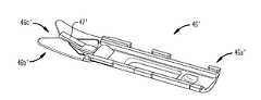
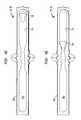
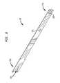
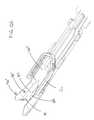
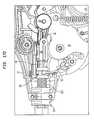
- FIG. 1Ais a side view of one exemplary embodiment of a surgical clip applier
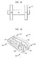
- FIG. 5Ais a side perspective view of an advancer that is configured to couple to a distal end of the feed bar shown in FIG. 4A ;
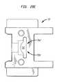
- FIG. 6Dis a cross-sectional view of the clip advancing assembly shown in FIG. 6C , showing the feed bar returned to the initial, proximal position, shown in FIG. 6A , while the feeder shoe and clip supply remain in the advanced position shown in FIG. 6C ;
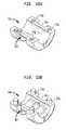
- FIG. 11Bis a top perspective view of another embodiment of a tissue stop having a ramp formed thereon for guiding a clip into the jaws and stabilizing the clip during clip formation;
- FIG. 11Fis another perspective view of the tissue stop of FIG. 11E ;
- FIG. 12Eis a perspective view of the advancer of FIG. 5C in a proximal position on the tissue stop of FIG. 11E ;
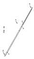
- FIG. 16is a top perspective view of a flexible link that forms part of a clip advancing assembly of the surgical clip applier shown in FIG. 1A ;
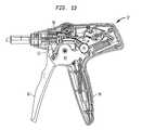
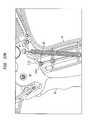
- FIG. 22Bis a side, partially cross-sectional view of a portion of the handle of the surgical clip applier shown in FIG. 22A , showing the anti-backup mechanism in a partially actuated position;
- FIG. 22Cis a side, partially cross-sectional view of a portion of the handle of the surgical clip applier shown in FIG. 22B , showing the anti-backup mechanism in a fully actuated position;
- the clip track 30can be configured to seat about twenty clips that are pre-disposed within the clip track 30 during manufacturing.
- shape, size, and configuration of the clip track 30can vary depending on the shape, size, and configuration of clips, or other closure devices such as staples, adapted to be received therein.
- a variety of other techniquescan be used, instead of a clip track 30 , to retain a clip supply with the elongate shaft 18 .
- the proximal end 38 a of the feed bar 38can include a feature to prevent compression of the opposed sides of the proximal end 28 a of the jaw retainer shaft 28 ( FIGS. 2A and 2B ) during use of the device to prevent accidental disengagement of the teeth 31 from the outer tube 24 .
- the proximal end 38 a of the feed bar 38can include a protrusion 39 formed thereon that is adapted to extend into the opening 29 formed in the proximal end 28 a of the jaw retainer shaft 28 .
- the feed bar 38can also include a feature to control the amount of movement of the feed bar 38 relative to the clip track 30 . Such a configuration will ensure that the feeder shoe 34 is advanced a predetermined distance each time the trigger 16 is actuated, thereby advancing only a single clip into the jaws 20 . While a variety of techniques can be used to control the distal of movement of the feed bar 38 , in an exemplary embodiment the feed bar 38 can include a protrusion 86 formed thereon that is adapted to be slidably received within a corresponding slot 88 ( FIG. 2B ) formed in the jaw retainer shaft 28 . The length of the slot 88 is effective to limit movement of the protrusion 86 therein, thus limiting movement of the feed bar 38 .
- a distal-facing surface 41 of the clip-pusher member 90 ′′can have a height H, measured in a superior/inferior direction, that is greater than a height (as measured in the same direction) of an apex of a clip pushed by the clip-pusher member 90 ′′, as will be described in more detail below.
- the increased heightcan result from a distal biasing surface 43 formed on an inferior surface of the tip 90 ′′ and located adjacent to the distal end 90 d ′′ of the tip 90 ′′.
- the distal biasing surface 43can be in the form of a ramped portion or a surface feature. As further shown in FIGS.
- FIGS. 6A-6Gillustrate the clip advancing assembly in use, and in particular FIGS. 6A-6D illustrate movement of the feed bar 38 within the clip track 30 to advance the feeder shoe 34 and clip supply 36 , and FIGS. 6E-6F illustrate movement of the advancer 40 to advance a distal-most clip into the jaws 20 .
- the components in the housing 12 that are used to actuate the clip advancing assemblywill be discussed in more detail below.
- the detents 84 in the feed barare labeled sequentially as 84 1 , 84 2 , etc.
- the openings 30 c in the clip track 30are labeled sequentially as 30 c 1 , 30 c 2 , etc.
- a series of clips 36labeled sequentially as 36 1 , 36 2 , . . . 36 x with 36 x being the distal-most clip, are positioned within the clip track 30 distal of the feeder shoe 34 .
- the distal portion 20 b of the jaws 20can be adapted to receive a clip therebetween, and thus the distal portion 20 b can include first and second opposed jaw members 96 a, 96 b that are movable relative to one another.
- the jaw members 96 a, 96 bare biased to an open position, and a force is required to move the jaw members 96 a, 96 b toward one another.
- the jaw members 96 a, 96 bcan each include a groove (only one groove 97 is shown) formed therein on opposed inner surfaces thereof for receiving the legs of a clip in alignment with the jaw members 96 a, 96 b.
- FIG. 8illustrates an exemplary cam 42 for slidably mating to and engaging the jaw members 96 , 96 b.
- the cam 42can have a variety of configurations, but in the illustrated embodiment it includes a proximal end 42 a that is adapted to mate to a push rod 44 , discussed in more detail below, and a distal end 42 b that is adapted to engage the jaw members 96 a, 96 b.
- a variety of techniquescan be used to mate the cam 42 to the push rod 44 , but in the illustrated exemplary embodiment the cam 42 includes a female or keyed cut-out 100 formed therein and adapted to receive a male or key member 102 formed on the distal end 44 b of the push rod 44 .
- the male member 102is shown in more detail in FIG. 9 , which illustrates the push rod 44 .
- the male member 102has a shape that corresponds to the shape of the cut-out 100 to allow the two members 42 , 44 to mate.
- the cam 42 and the push rod 44can optionally be integrally formed with one another.
- the proximal end 44 a of the push rod 44can be adapted to mate to a closure link assembly, discussed in more detail below, for moving the push rod 44 and the cam 42 relative to the jaws 20 .
- the surgical clip applier 10can also include a tissue stop 46 for facilitating positioning of the tissue at the surgical site within jaws 20 .
- FIG. 11Ashows one exemplary embodiment of a tissue stop 46 having proximal end and distal ends 46 a, 46 b.
- the proximal end 46 acan be adapted to mate to a distal end of the clip track 30 for positioning the tissue stop 46 adjacent to the jaws 20 .
- the tissue stop 46can be integrally formed with the clip track 30 , or it can be adapted to mate to or be integrally formed with a variety of other components of the shaft 18 .
- the distal end 46 b of the tissue stop 46can have a shape that is adapted to seat a vessel, duct, shunt, etc.
- the tissue stop, or other components of the devicecan also optionally include features to support and stabilize a clip during clip formation.
- the clipWhen a clip is being formed between the jaws, the clip can pivot and become misaligned.
- the terminal end of each leg of the clipwill be moved toward one another.
- the jawswill only engage a bend portion on each leg, thus allowing the terminal ends of the legs and the apex of the clip to swing out of alignment with the jaws, i.e., to pivot vertically relative to the jaws. Further closure of the jaws can thus result in a malformed clip.
- the devicecan include features to align and guide the clip into the jaws, and to prevent the clip from pivoting or otherwise becoming misaligned during clip formation.
- FIG. 11Aillustrates a central tang 47 formed at a mid-portion of the distal end 46 b of the tissue stop 46 for maintaining a clip in alignment with the tip of the advancer assembly 40 .
- the central tang 47can allow the apex of a clip to ride therealong thus preventing the clip from becoming misaligned relative to the advancer assembly 40 that is pushing the clip in a distal direction.
- the tissue stop 46can have a variety of other configurations, and it can include a variety of other features to facilitate advancement of a clip therealong.
- FIG. 12Aillustrates the tissue stop 46 in use.
- the tissue stop 46is positioned just inferior to the jaws 20 and at a location that allows a vessel, duct, shunt etc. to be received between the jaws 20 .
- a surgical clip 36is positioned between the jaws 20 such that the bight portion 36 a of the clip 36 is aligned with the tissue stop 46 . This will allow the legs 36 b of the clip 36 to be fully positioned around the vessel, duct, shunt, or other target site.
- the clipwhen the clip is pushed into the jaws 20 , the clip must reorient itself to accommodate the angle of the jaws 20 .
- This reorientationcan cause an apex of the clip to drop vertically or rotate downward (in an inferior direction) relative to the opposed legs of the clip. This drop may prevent the clip from being positioned properly within the jaws 20 .
- the apex of the clipmay drop below a distal end of the clip-pusher member such that the clip-pusher member bypasses the clip and moves over top of its apex. The clip-pusher member would then be unable to properly position the clip within the jaws 20 .
- the distal-facing surface 41is able to maintain contact with the apex of the clip C at all times and is therefore able to position the clip C properly within the jaws 20 .
- the distal-facing surface 41can also maintain contact with the apex of the clip C at all times during forming of the clip C between the jaws 20 to ensure that the clip C does not move proximally.
- the distal-facing surface 41moves proximal to the apex of the clip C 1 .
- the proximal biasing surface 45contacts the proximal ramp 53 and begins to move up the proximal ramp 53 . Since the superior surface 47 of the distal tip 90 ′′ is no longer in contact with the inferior surface of the clip C 1 , when the proximal biasing surface 45 travels up the proximal ramp 53 , the distal tip 90 ′′ deflects back up in a superior direction such that it is of a substantially even height with the apex of the clip C 1 once again, as shown most clearly in FIG. 12E .
- exemplary featuresinclude an anti-backup mechanism for controlling movement of the trigger 16 , an overload mechanism for preventing overload of the force applied to the jaws 20 by the clip forming assembly, and a clip quantity indicator for indicating a quantity of clips remaining in the device 10 .
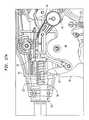
- FIG. 19An exemplary embodiment of a closure link 56 is shown in more detail in FIG. 19 , and as shown it has opposed arms 126 a, 126 b that are spaced a distance apart from one another.
- Each arm 126 a, 126 bincludes a proximal end 128 a, 128 b that is adapted to engage the central shaft 54 a of the closure link roller 54 , and a distal end 130 a, 130 b that is adapted to mate to a closure coupler 58 for coupling the closure link roller 54 and closure link 56 to the push rod 44 .
- the ridges 59 a ′, 59 b ′will prevent the cantilevered beam from deflecting, thereby preventing the load of the spring or cantilevered beam from transferring from the terminal ends inward.
- a person skilled in the artwill appreciate that the particular location, quantity, and size of the ridges 59 a ′, 59 b ′ can vary depending on the configuration of the preloaded joint, as well as the forces necessary to prevent clip fallout during closure.
- the cam 42is advanced over the jaws 20 to close the jaws 20 and crimp the clip positioned therebetween.
- the trigger 16can optionally be partially closed to only partially close the jaws 20 and thus partially crimp a clip disposed therebetween. Exemplary techniques for facilitating selective full and partial closure of the clip will be discussed in more detail below.
- the trigger 16can be released thereby allowing spring 120 to pull the trigger insert 48 back to its initial position, and allowing spring 122 to force the feed bar coupler 50 and feed bar 38 back to the proximal position.
- the closure link roller 54is moved back to its initial position as well, thereby pulling the closure link 56 , closure coupler 58 , and push bar 44 proximally.
- the opening in the housingallows the closure link roller of the clip forming assembly to roll against the profile link.
- the closure link rollerapplies a force to the profile link.
- the resistance of the overload springwill, however, maintain the profile link in a substantially fixed position unless the force applied by the closure link roller increases to a force that is greater than the resistance, e.g., a threshold force. This can be caused by, for example, a foreign object positioned between the jaws 20 or when the jaws 20 are fully closed with the clip and vessel, duct, shunt, etc. therebetween.
- the amount of force required to actuate the overload mechanismcan be greater than and can increase relative to the amount of force required to close the jaws 20
- the forceis preferably only slightly greater than the force required to close the jaws 20 to prevent deformation or other damage to the jaws 20 .
- the resistancecan be adjusted based on the force necessary to close the jaws 20 .
- the surgical clip applier 10can be used to apply a partially or fully closed clip to a surgical site, such as a vessel, duct, shunt, etc.
- a surgical sitesuch as a vessel, duct, shunt, etc.
- a small incisionis made in the patient's body to provide access to a surgical site.
- a cannula or access portis typically used to define a working channel extending from the skin incision to the surgical site.
- a surgical clipcan thus be used to crimp the vessel or to secure the shunt to the vessel.
Landscapes
- Health & Medical Sciences (AREA)
- Surgery (AREA)
- Life Sciences & Earth Sciences (AREA)
- Heart & Thoracic Surgery (AREA)
- Nuclear Medicine, Radiotherapy & Molecular Imaging (AREA)
- Vascular Medicine (AREA)
- Engineering & Computer Science (AREA)
- Biomedical Technology (AREA)
- Reproductive Health (AREA)
- Medical Informatics (AREA)
- Molecular Biology (AREA)
- Animal Behavior & Ethology (AREA)
- General Health & Medical Sciences (AREA)
- Public Health (AREA)
- Veterinary Medicine (AREA)
- Surgical Instruments (AREA)
Abstract
Description
Claims (20)
Priority Applications (17)
| Application Number | Priority Date | Filing Date | Title |
|---|---|---|---|
| US12/576,736US8262679B2 (en) | 2009-10-09 | 2009-10-09 | Clip advancer |
| US12/628,662US8267945B2 (en) | 2009-10-09 | 2009-12-01 | Clip advancer with lockout mechanism |
| CA2777212ACA2777212C (en) | 2009-10-09 | 2010-10-04 | Improved clip advancer |
| EP10765904.7AEP2485659B9 (en) | 2009-10-09 | 2010-10-04 | Clip advancer with lockout mechanism |
| CN201080056061.XACN102781344B (en) | 2009-10-09 | 2010-10-04 | Gripper pusher with locking mechanism |
| BR112012008261ABR112012008261B1 (en) | 2009-10-09 | 2010-10-04 | surgical clip applicator |
| CN201080055707.2ACN102647948B (en) | 2009-10-09 | 2010-10-04 | Improved clip advancer |
| CA2777040ACA2777040C (en) | 2009-10-09 | 2010-10-04 | Clip advancer with lockout mechanism |
| PCT/US2010/051314WO2011044039A1 (en) | 2009-10-09 | 2010-10-04 | Clip advancer with lockout mechanism |
| AU2010303722AAU2010303722B2 (en) | 2009-10-09 | 2010-10-04 | Improved clip advancer |
| EP10765903.9AEP2485658B1 (en) | 2009-10-09 | 2010-10-04 | Improved clip advancer |
| RU2012118651/14ARU2549990C2 (en) | 2009-10-09 | 2010-10-04 | Clip feed unit with locking mechanism |
| RU2012118670/14ARU2597771C2 (en) | 2009-10-09 | 2010-10-04 | Improved clip advancer |
| PCT/US2010/051305WO2011044035A2 (en) | 2009-10-09 | 2010-10-04 | Improved clip advancer |
| BR112012008264-7ABR112012008264B1 (en) | 2009-10-09 | 2010-10-04 | SURGICAL CLIP APPLICATOR AND METHOD FOR ADVANCING A CLIP INTO OPPOSITE JAWS OF A CLIP APPLICATOR |
| AU2010303726AAU2010303726B2 (en) | 2009-10-09 | 2010-10-04 | Clip advancer with lockout mechanism |
| US13/111,378US8496673B2 (en) | 2009-10-09 | 2011-05-19 | Clip advancer with lockout mechanism |
Applications Claiming Priority (1)
| Application Number | Priority Date | Filing Date | Title |
|---|---|---|---|
| US12/576,736US8262679B2 (en) | 2009-10-09 | 2009-10-09 | Clip advancer |
Related Child Applications (1)
| Application Number | Title | Priority Date | Filing Date |
|---|---|---|---|
| US12/628,662Continuation-In-PartUS8267945B2 (en) | 2009-10-09 | 2009-12-01 | Clip advancer with lockout mechanism |
Publications (2)
| Publication Number | Publication Date |
|---|---|
| US20110087241A1 US20110087241A1 (en) | 2011-04-14 |
| US8262679B2true US8262679B2 (en) | 2012-09-11 |
Family
ID=43256587
Family Applications (1)
| Application Number | Title | Priority Date | Filing Date |
|---|---|---|---|
| US12/576,736Active2030-09-15US8262679B2 (en) | 2009-10-09 | 2009-10-09 | Clip advancer |
Country Status (8)
| Country | Link |
|---|---|
| US (1) | US8262679B2 (en) |
| EP (1) | EP2485658B1 (en) |
| CN (1) | CN102647948B (en) |
| AU (1) | AU2010303722B2 (en) |
| BR (1) | BR112012008264B1 (en) |
| CA (1) | CA2777212C (en) |
| RU (1) | RU2597771C2 (en) |
| WO (1) | WO2011044035A2 (en) |
Cited By (115)
| Publication number | Priority date | Publication date | Assignee | Title |
|---|---|---|---|---|
| US20080027465A1 (en)* | 2005-04-14 | 2008-01-31 | Ethicon Endo-Surgery, Inc. | Surgical clip applier methods |
| US8496673B2 (en) | 2009-10-09 | 2013-07-30 | Ethicon Endo-Surgery, Inc. | Clip advancer with lockout mechanism |
| US8523882B2 (en) | 2005-04-14 | 2013-09-03 | Ethicon Endo-Surgery, Inc. | Clip advancer mechanism with alignment features |
| US8734469B2 (en) | 2009-10-13 | 2014-05-27 | Covidien Lp | Suture clip applier |
| US8747423B2 (en) | 2007-03-26 | 2014-06-10 | Covidien Lp | Endoscopic surgical clip applier |
| US8821516B2 (en) | 2005-04-14 | 2014-09-02 | Ethicon Endo-Surgery, Inc. | Clip applier with migrational resistance features |
| US8845659B2 (en) | 2010-02-25 | 2014-09-30 | Covidien Lp | Articulating endoscopic surgical clip applier |
| US8894665B2 (en) | 2008-08-29 | 2014-11-25 | Covidien Lp | Endoscopic surgical clip applier |
| US8915930B2 (en) | 2005-04-14 | 2014-12-23 | Ethicon Endo-Surgery, Inc. | Force limiting mechanism for medical instrument |
| US8920438B2 (en) | 2004-10-08 | 2014-12-30 | Covidien Lp | Apparatus for applying surgical clips |
| US8961542B2 (en) | 2010-07-28 | 2015-02-24 | Covidien Lp | Articulating clip applier cartridge |
| US8968337B2 (en) | 2010-07-28 | 2015-03-03 | Covidien Lp | Articulating clip applier |
| US9011464B2 (en) | 2010-11-02 | 2015-04-21 | Covidien Lp | Self-centering clip and jaw |
| US9011465B2 (en) | 2004-10-08 | 2015-04-21 | Covidien Lp | Endoscopic surgical clip applier |
| US9113892B2 (en) | 2013-01-08 | 2015-08-25 | Covidien Lp | Surgical clip applier |
| US9186153B2 (en) | 2011-01-31 | 2015-11-17 | Covidien Lp | Locking cam driver and jaw assembly for clip applier |
| US9186136B2 (en) | 2009-12-09 | 2015-11-17 | Covidien Lp | Surgical clip applier |
| US9220508B2 (en) | 2013-09-06 | 2015-12-29 | Ethicon Endo-Surgery, Inc. | Surgical clip applier with articulation section |
| US9271737B2 (en) | 2011-09-15 | 2016-03-01 | Teleflex Medical Incorporated | Automatic surgical ligation clip applier |
| US9358015B2 (en) | 2008-08-29 | 2016-06-07 | Covidien Lp | Endoscopic surgical clip applier with wedge plate |
| US9364216B2 (en) | 2011-12-29 | 2016-06-14 | Covidien Lp | Surgical clip applier with integrated clip counter |
| US9364239B2 (en) | 2011-12-19 | 2016-06-14 | Covidien Lp | Jaw closure mechanism for a surgical clip applier |
| US9370400B2 (en) | 2011-10-19 | 2016-06-21 | Ethicon Endo-Surgery, Inc. | Clip applier adapted for use with a surgical robot |
| US9408610B2 (en) | 2012-05-04 | 2016-08-09 | Covidien Lp | Surgical clip applier with dissector |
| US9414844B2 (en) | 2008-08-25 | 2016-08-16 | Covidien Lp | Surgical clip appliers |
| US9439654B2 (en) | 2008-08-29 | 2016-09-13 | Covidien Lp | Endoscopic surgical clip applier |
| US9480477B2 (en) | 2006-10-17 | 2016-11-01 | Covidien Lp | Apparatus for applying surgical clips |
| US9498227B2 (en) | 2007-04-11 | 2016-11-22 | Covidien Lp | Surgical clip applier |
| US9526501B2 (en) | 2009-12-15 | 2016-12-27 | Covidien Lp | Surgical clip applier |
| US9532787B2 (en) | 2012-05-31 | 2017-01-03 | Covidien Lp | Endoscopic clip applier |
| US9597089B2 (en) | 2010-03-10 | 2017-03-21 | Conmed Corporation | Surgical clips for laparoscopic procedures |
| US9750500B2 (en) | 2013-01-18 | 2017-09-05 | Covidien Lp | Surgical clip applier |
| US9763668B2 (en) | 2004-10-08 | 2017-09-19 | Covidien Lp | Endoscopic surgical clip applier |
| US9775624B2 (en) | 2013-08-27 | 2017-10-03 | Covidien Lp | Surgical clip applier |
| US9775623B2 (en) | 2011-04-29 | 2017-10-03 | Covidien Lp | Surgical clip applier including clip relief feature |
| US9931124B2 (en) | 2015-01-07 | 2018-04-03 | Covidien Lp | Reposable clip applier |
| US9968362B2 (en) | 2013-01-08 | 2018-05-15 | Covidien Lp | Surgical clip applier |
| US9968363B2 (en) | 2014-10-20 | 2018-05-15 | Joseph W. Blake, III | Multi-clip applier |
| US10098641B1 (en) | 2014-08-21 | 2018-10-16 | Joseph W Blake, III | Jaws and cams for clip applying instruments |
| US10159491B2 (en) | 2015-03-10 | 2018-12-25 | Covidien Lp | Endoscopic reposable surgical clip applier |
| US10201353B2 (en) | 2017-02-03 | 2019-02-12 | Pavel Menn | Ligation clip |
| US10292712B2 (en) | 2015-01-28 | 2019-05-21 | Covidien Lp | Surgical clip applier with integrated cutter |
| US10307166B2 (en) | 2011-09-15 | 2019-06-04 | Teleflex Medical Incorporated | Manual surgical ligation clip applier |
| US10390831B2 (en) | 2015-11-10 | 2019-08-27 | Covidien Lp | Endoscopic reposable surgical clip applier |
| US10405862B2 (en) | 2016-04-21 | 2019-09-10 | Applied Medical Resources Corporation | Laparoscopic clip applier |
| US10426489B2 (en) | 2016-11-01 | 2019-10-01 | Covidien Lp | Endoscopic reposable surgical clip applier |
| US10492795B2 (en) | 2016-11-01 | 2019-12-03 | Covidien Lp | Endoscopic surgical clip applier |
| US10548602B2 (en) | 2017-02-23 | 2020-02-04 | Covidien Lp | Endoscopic surgical clip applier |
| US10582931B2 (en) | 2016-02-24 | 2020-03-10 | Covidien Lp | Endoscopic reposable surgical clip applier |
| US10603038B2 (en) | 2017-02-22 | 2020-03-31 | Covidien Lp | Surgical clip applier including inserts for jaw assembly |
| US10610236B2 (en) | 2016-11-01 | 2020-04-07 | Covidien Lp | Endoscopic reposable surgical clip applier |
| US10639032B2 (en) | 2017-06-30 | 2020-05-05 | Covidien Lp | Endoscopic surgical clip applier including counter assembly |
| US10639044B2 (en) | 2016-10-31 | 2020-05-05 | Covidien Lp | Ligation clip module and clip applier |
| US10653429B2 (en) | 2017-09-13 | 2020-05-19 | Covidien Lp | Endoscopic surgical clip applier |
| US10660723B2 (en) | 2017-06-30 | 2020-05-26 | Covidien Lp | Endoscopic reposable surgical clip applier |
| US10660651B2 (en) | 2016-10-31 | 2020-05-26 | Covidien Lp | Endoscopic reposable surgical clip applier |
| US10660725B2 (en) | 2017-02-14 | 2020-05-26 | Covidien Lp | Endoscopic surgical clip applier including counter assembly |
| US10675043B2 (en) | 2017-05-04 | 2020-06-09 | Covidien Lp | Reposable multi-fire surgical clip applier |
| US10675112B2 (en) | 2017-08-07 | 2020-06-09 | Covidien Lp | Endoscopic surgical clip applier including counter assembly |
| EP3673837A2 (en) | 2018-12-31 | 2020-07-01 | Ethicon LLC | Multi-piece jaw assembly for surgical clip applier |
| US10702278B2 (en) | 2014-12-02 | 2020-07-07 | Covidien Lp | Laparoscopic surgical ligation clip applier |
| US10702280B2 (en) | 2015-11-10 | 2020-07-07 | Covidien Lp | Endoscopic reposable surgical clip applier |
| US10702279B2 (en) | 2015-11-03 | 2020-07-07 | Covidien Lp | Endoscopic surgical clip applier |
| US10709455B2 (en) | 2017-02-02 | 2020-07-14 | Covidien Lp | Endoscopic surgical clip applier |
| US10722236B2 (en) | 2017-12-12 | 2020-07-28 | Covidien Lp | Endoscopic reposable surgical clip applier |
| US10722235B2 (en) | 2017-05-11 | 2020-07-28 | Covidien Lp | Spring-release surgical clip |
| US10743887B2 (en) | 2017-12-13 | 2020-08-18 | Covidien Lp | Reposable multi-fire surgical clip applier |
| US10758245B2 (en) | 2017-09-13 | 2020-09-01 | Covidien Lp | Clip counting mechanism for surgical clip applier |
| US10758244B2 (en) | 2017-02-06 | 2020-09-01 | Covidien Lp | Endoscopic surgical clip applier |
| US10765431B2 (en) | 2016-01-18 | 2020-09-08 | Covidien Lp | Endoscopic surgical clip applier |
| US10779838B1 (en) | 2013-11-13 | 2020-09-22 | Joseph W Blake, III | Instrument for serially applying clips to a surgical site |
| US10786263B2 (en) | 2017-08-15 | 2020-09-29 | Covidien Lp | Endoscopic reposable surgical clip applier |
| US10786262B2 (en) | 2017-08-09 | 2020-09-29 | Covidien Lp | Endoscopic reposable surgical clip applier |
| US10786273B2 (en) | 2018-07-13 | 2020-09-29 | Covidien Lp | Rotation knob assemblies for handle assemblies |
| US10806463B2 (en) | 2011-11-21 | 2020-10-20 | Covidien Lp | Surgical clip applier |
| US10806464B2 (en) | 2016-08-11 | 2020-10-20 | Covidien Lp | Endoscopic surgical clip applier and clip applying systems |
| US10828036B2 (en) | 2017-11-03 | 2020-11-10 | Covidien Lp | Endoscopic surgical clip applier and handle assemblies for use therewith |
| US10835341B2 (en) | 2017-09-12 | 2020-11-17 | Covidien Lp | Endoscopic surgical clip applier and handle assemblies for use therewith |
| US10835260B2 (en) | 2017-09-13 | 2020-11-17 | Covidien Lp | Endoscopic surgical clip applier and handle assemblies for use therewith |
| US10849630B2 (en) | 2017-12-13 | 2020-12-01 | Covidien Lp | Reposable multi-fire surgical clip applier |
| US10863992B2 (en) | 2017-08-08 | 2020-12-15 | Covidien Lp | Endoscopic surgical clip applier |
| US10905425B2 (en) | 2015-11-10 | 2021-02-02 | Covidien Lp | Endoscopic reposable surgical clip applier |
| US10932793B2 (en) | 2016-01-11 | 2021-03-02 | Covidien Lp | Endoscopic reposable surgical clip applier |
| US10932791B2 (en) | 2017-11-03 | 2021-03-02 | Covidien Lp | Reposable multi-fire surgical clip applier |
| US10932790B2 (en) | 2017-08-08 | 2021-03-02 | Covidien Lp | Geared actuation mechanism and surgical clip applier including the same |
| US10945734B2 (en) | 2017-11-03 | 2021-03-16 | Covidien Lp | Rotation knob assemblies and surgical instruments including the same |
| US10959737B2 (en) | 2017-12-13 | 2021-03-30 | Covidien Lp | Reposable multi-fire surgical clip applier |
| US10993721B2 (en) | 2018-04-25 | 2021-05-04 | Covidien Lp | Surgical clip applier |
| US11051827B2 (en) | 2018-01-16 | 2021-07-06 | Covidien Lp | Endoscopic surgical instrument and handle assemblies for use therewith |
| US11051809B2 (en) | 2018-12-31 | 2021-07-06 | Cilag Gmbh International | Cartridge receiving jaw for surgical stapler and associated method of manufacture with MIM |
| US11051828B2 (en) | 2018-08-13 | 2021-07-06 | Covidien Lp | Rotation knob assemblies and surgical instruments including same |
| US11058432B2 (en) | 2015-01-15 | 2021-07-13 | Covidien Lp | Endoscopic reposable surgical clip applier |
| US11071553B2 (en) | 2016-08-25 | 2021-07-27 | Covidien Lp | Endoscopic surgical clip applier and clip applying systems |
| US11103245B2 (en) | 2018-12-31 | 2021-08-31 | Cilag Gmbh International | Knife for surgical stapler and associated method of manufacture with MIM and hip |
| US11116514B2 (en) | 2017-02-06 | 2021-09-14 | Covidien Lp | Surgical clip applier with user feedback feature |
| US11116513B2 (en) | 2017-11-03 | 2021-09-14 | Covidien Lp | Modular surgical clip cartridge |
| US11134941B2 (en) | 2018-12-31 | 2021-10-05 | Cilag Gmbh International | Cartridge receiving jaw for surgical stapler and associated method of manufacture with stamping |
| US11147566B2 (en) | 2018-10-01 | 2021-10-19 | Covidien Lp | Endoscopic surgical clip applier |
| US11219463B2 (en) | 2018-08-13 | 2022-01-11 | Covidien Lp | Bilateral spring for surgical instruments and surgical instruments including the same |
| US11246601B2 (en) | 2018-08-13 | 2022-02-15 | Covidien Lp | Elongated assemblies for surgical clip appliers and surgical clip appliers incorporating the same |
| US11259804B2 (en) | 2018-12-31 | 2022-03-01 | Cilag Gmbh International | Frame for surgical stapler and associated method of manufacture with stamping |
| US11278267B2 (en) | 2018-08-13 | 2022-03-22 | Covidien Lp | Latch assemblies and surgical instruments including the same |
| US11291450B2 (en) | 2018-12-31 | 2022-04-05 | Cilag Gmbh International | Anvil for circular surgical stapler and associated method of manufacture with MIM |
| US11344316B2 (en) | 2018-08-13 | 2022-05-31 | Covidien Lp | Elongated assemblies for surgical clip appliers and surgical clip appliers incorporating the same |
| US11376015B2 (en) | 2017-11-03 | 2022-07-05 | Covidien Lp | Endoscopic surgical clip applier and handle assemblies for use therewith |
| US11510682B2 (en) | 2008-08-25 | 2022-11-29 | Covidien Lp | Surgical clip applier and method of assembly |
| US11524398B2 (en) | 2019-03-19 | 2022-12-13 | Covidien Lp | Gear drive mechanisms for surgical instruments |
| US11583291B2 (en) | 2017-02-23 | 2023-02-21 | Covidien Lp | Endoscopic surgical clip applier |
| US11607217B2 (en) | 2018-12-31 | 2023-03-21 | Cilag Gmbh International | Surgical stapler shaft formed of segments of different materials |
| US11723669B2 (en) | 2020-01-08 | 2023-08-15 | Covidien Lp | Clip applier with clip cartridge interface |
| US11779340B2 (en) | 2020-01-02 | 2023-10-10 | Covidien Lp | Ligation clip loading device |
| US11992218B2 (en) | 2021-10-18 | 2024-05-28 | Cilag Gmbh International | Metal injection molded anvil for circular surgical stapler |
| US12114866B2 (en) | 2020-03-26 | 2024-10-15 | Covidien Lp | Interoperative clip loading device |
| US12336716B2 (en) | 2022-08-05 | 2025-06-24 | Megaflex Surgical Corporation | Surgical clip applier |
| US12419648B2 (en) | 2022-09-26 | 2025-09-23 | Covidien Lp | Two-part fasteners for surgical clip appliers and surgical clip appliers for deploying the same |
Families Citing this family (21)
| Publication number | Priority date | Publication date | Assignee | Title |
|---|---|---|---|---|
| US7261724B2 (en) | 2005-04-14 | 2007-08-28 | Ethicon Endo-Surgery, Inc. | Surgical clip advancement mechanism |
| US7686820B2 (en) | 2005-04-14 | 2010-03-30 | Ethicon Endo-Surgery, Inc. | Surgical clip applier ratchet mechanism |
| US8038686B2 (en)* | 2005-04-14 | 2011-10-18 | Ethicon Endo-Surgery, Inc. | Clip applier configured to prevent clip fallout |
| US8262679B2 (en) | 2009-10-09 | 2012-09-11 | Ethicon Endo-Surgery, Inc. | Clip advancer |
| US9017347B2 (en) | 2011-12-22 | 2015-04-28 | Edwards Lifesciences Corporation | Suture clip deployment devices |
| US10016193B2 (en) | 2013-11-18 | 2018-07-10 | Edwards Lifesciences Ag | Multiple-firing crimp device and methods for using and manufacturing same |
| US9498202B2 (en) | 2012-07-10 | 2016-11-22 | Edwards Lifesciences Corporation | Suture securement devices |
| WO2015006739A1 (en) | 2013-07-11 | 2015-01-15 | Edwards Lifesciences Corporation | Knotless suture fastener installation system |
| WO2015183749A1 (en) | 2014-05-30 | 2015-12-03 | Edwards Lifesciences Corporation | Systems for securing sutures |
| EP3229703B1 (en) | 2014-12-10 | 2024-08-28 | Edwards Lifesciences AG | Multiple-firing securing device |
| CN104490446B (en)* | 2014-12-12 | 2017-01-25 | 浙江微度医疗器械有限公司 | Clip applier capable of continuously releasing hemostatic clips |
| WO2016105511A1 (en) | 2014-12-24 | 2016-06-30 | Edwards Lifesciences Corporation | Suture clip deployment devices |
| US10470759B2 (en) | 2015-03-16 | 2019-11-12 | Edwards Lifesciences Corporation | Suture securement devices |
| CN106344101A (en)* | 2015-07-07 | 2017-01-25 | 北京天钥医疗器械有限公司 | Clip applier for medical use and the safety device thereof |
| US10939905B2 (en) | 2016-08-26 | 2021-03-09 | Edwards Lifesciences Corporation | Suture clips, deployment devices therefor, and methods of use |
| US10863980B2 (en) | 2016-12-28 | 2020-12-15 | Edwards Lifesciences Corporation | Suture fastener having spaced-apart layers |
| US10959732B2 (en) | 2017-08-10 | 2021-03-30 | Ethicon Llc | Jaw for clip applier |
| US10675031B2 (en) | 2017-08-10 | 2020-06-09 | Ethicon Llc | Clip retention for surgical clip applier |
| WO2021252817A1 (en)* | 2020-06-10 | 2021-12-16 | The Regents Of The University Of California | Endoscopic stapler and staple remover |
| WO2023028913A1 (en)* | 2021-09-01 | 2023-03-09 | Covidien Lp | Audible feedback for curved stapling device |
| TWI780019B (en)* | 2022-05-06 | 2022-10-01 | 台灣先進手術醫療器材股份有限公司 | A surgical clip applier with locking structure |
Citations (224)
| Publication number | Priority date | Publication date | Assignee | Title |
|---|---|---|---|---|
| FR900376A (en) | 1943-12-04 | 1945-06-27 | Universal tractor for small farms | |
| US2968041A (en) | 1958-09-25 | 1961-01-17 | John F Skold | Applicator for surgical clamps |
| DE1993372U (en) | 1965-10-18 | 1968-09-05 | Richard Lietz | MOTOR VEHICLE REVIEW MIRROR. |
| US3459029A (en) | 1967-02-28 | 1969-08-05 | Buchanan Electric Products Cor | Adjustable crimping tool |
| US4038987A (en) | 1974-02-08 | 1977-08-02 | Olympus Optical Co., Ltd. | Forceps device for endoscope |
| US4064881A (en) | 1975-06-06 | 1977-12-27 | Rocket Of London Limited | Surgical clip applicator |
| US4080820A (en) | 1976-09-02 | 1978-03-28 | Walter Kidde & Company, Inc. | In-line crimping tool |
| US4152920A (en) | 1977-10-17 | 1979-05-08 | United States Surgical Corporation | System for applying surgical clips |
| US4188953A (en) | 1977-08-05 | 1980-02-19 | Charles H. Klieman, M.D. | Hemostatic clip |
| US4242902A (en) | 1978-05-11 | 1981-01-06 | United States Surgical Corporation | Surgical clip applicator |
| US4296751A (en) | 1979-08-02 | 1981-10-27 | Blake Joseph W Iii | Surgical device |
| US4298072A (en) | 1979-08-31 | 1981-11-03 | Senco Products, Inc. | Control arrangement for electro-mechanical tool |
| US4372316A (en) | 1979-08-02 | 1983-02-08 | Blake Joseph W Iii | Surgical device |
| US4408603A (en) | 1980-10-24 | 1983-10-11 | Blake Joseph W Iii | Surgical device |
| US4448193A (en) | 1982-02-26 | 1984-05-15 | Ethicon, Inc. | Surgical clip applier with circular clip magazine |
| US4449530A (en) | 1981-07-15 | 1984-05-22 | Ethicon, Inc. | Hemostatic clips and method of manufacture |
| US4452376A (en) | 1977-08-05 | 1984-06-05 | Charles H. Klieman | Hemostatic clip applicator |
| US4513746A (en) | 1981-10-09 | 1985-04-30 | United States Surgical Corp. | Instrument for applying plastic-like surgical fastening devices |
| US4522207A (en) | 1981-02-06 | 1985-06-11 | Charles H. Klieman | Spring activated hemostatic clip applicator |
| US4532925A (en) | 1979-08-02 | 1985-08-06 | Joseph W. Blake, III | Ligator device |
| US4556058A (en) | 1983-08-17 | 1985-12-03 | United States Surgical Corporation | Apparatus for ligation and division with fixed jaws |
| US4557263A (en) | 1984-01-23 | 1985-12-10 | United States Surgical Corporation | Apparatus for applying surgical clips |
| US4576165A (en) | 1984-01-23 | 1986-03-18 | United States Surgical Corporation | Surgical ligation and cutting device with safety means |
| US4588580A (en) | 1984-07-23 | 1986-05-13 | Alza Corporation | Transdermal administration of fentanyl and device therefor |
| US4590937A (en) | 1985-01-07 | 1986-05-27 | American Cyanamid Company | Nonmetallic surgical clip |
| DE3490145C2 (en) | 1983-03-30 | 1986-08-07 | United States Surgical Corp., Norwalk, Conn. | Instrument for tying and severing an organic tissue structure |
| DE3152411C2 (en) | 1980-10-03 | 1986-08-21 | United States Surgical Corp., Norwalk, Conn. | Surgical instrument for ligating and severing tissue in the body |
| US4611595A (en) | 1977-08-05 | 1986-09-16 | Charles H. Klieman | Spring activated hemostatic clip applicator |
| US4616650A (en) | 1984-07-27 | 1986-10-14 | United States Surgical Corporation | Apparatus for applying surgical clips |
| US4651737A (en) | 1984-10-15 | 1987-03-24 | American Cyanamid Company | Nonmetallic surgical clip |
| US4662374A (en) | 1979-08-02 | 1987-05-05 | American Hospital Supply Corp. | Ligator device |
| US4674504A (en) | 1982-10-06 | 1987-06-23 | Klieman Charles H | Spring activated hemostatic clip applicator |
| US4676504A (en) | 1986-01-21 | 1987-06-30 | Ponza Larry J | Tennis and baseball dispensing apparatus |
| US4702274A (en) | 1986-06-17 | 1987-10-27 | Martinson Manufacturing Company, Inc. | Quick disconnect for sewage system |
| US4712549A (en) | 1985-07-01 | 1987-12-15 | Edward Weck & Co. | Automatic hemostatic clip applier |
| US4741336A (en) | 1984-07-16 | 1988-05-03 | Ethicon, Inc. | Shaped staples and slotted receivers (case VII) |
| US4799481A (en) | 1987-04-08 | 1989-01-24 | Ethicon, Inc. | Surgical hemostatic clips |
| US4834096A (en) | 1987-10-26 | 1989-05-30 | Edward Weck Incorporated | Plastic ligating clips |
| US4844066A (en) | 1987-04-06 | 1989-07-04 | Richard-Allan Medical Industries, Inc. | Surgical clip |
| US4850355A (en) | 1987-04-06 | 1989-07-25 | Richard-Allan Medical Industries, Inc. | Hemostatic clip applicator for applying multiple hemostatic clips |
| SU1560125A1 (en) | 1988-07-29 | 1990-04-30 | Челябинский государственный медицинский институт | Microsurgical fixative |
| US4976722A (en) | 1989-05-22 | 1990-12-11 | Ethicon, Inc. | Surgical hemostatic clips |
| US4979950A (en) | 1987-04-08 | 1990-12-25 | Ethicon, Inc. | Surgical hemostatic clips |
| US5009661A (en) | 1989-04-24 | 1991-04-23 | Michelson Gary K | Protective mechanism for surgical rongeurs |
| US5012666A (en) | 1989-07-24 | 1991-05-07 | Chen Ching Wen | Crimp tool with adjustable jaw |
| US5030226A (en) | 1988-01-15 | 1991-07-09 | United States Surgical Corporation | Surgical clip applicator |
| US5047038A (en) | 1985-07-01 | 1991-09-10 | Edward Weck Incorporated | Automatic hemostatic clip applier |
| US5049152A (en) | 1989-03-07 | 1991-09-17 | Richard-Allan Medical Industries | Hemostatic clip applicator |
| US5062846A (en) | 1989-03-28 | 1991-11-05 | Edward Weck Incorporated | Penetrating plastic ligating clip |
| DE4015562A1 (en) | 1990-05-15 | 1991-11-21 | Storz Karl | Fitting clips around blood vessels - involves tubular extension to jaws to hold required number of clips |
| US5084057A (en) | 1989-07-18 | 1992-01-28 | United States Surgical Corporation | Apparatus and method for applying surgical clips in laparoscopic or endoscopic procedures |
| US5086901A (en) | 1991-02-14 | 1992-02-11 | Applied Robotics, Inc. | Robot overload detection device |
| US5100420A (en) | 1989-07-18 | 1992-03-31 | United States Surgical Corporation | Apparatus and method for applying surgical clips in laparoscopic or endoscopic procedures |
| US5100416A (en) | 1989-10-17 | 1992-03-31 | Edward Weck Incorporated | Ligating clip applying instrument |
| US5104395A (en) | 1989-07-03 | 1992-04-14 | Edward Weck Incorporated | Automatic hemostatic clip applicator |
| US5112343A (en) | 1991-04-05 | 1992-05-12 | Edward Weck Incorporated | Endoscopic clip appliers |
| US5116349A (en) | 1990-05-23 | 1992-05-26 | United States Surgical Corporation | Surgical fastener apparatus |
| US5127730A (en) | 1990-08-10 | 1992-07-07 | Regents Of The University Of Minnesota | Multi-color laser scanning confocal imaging system |
| US5129885A (en) | 1990-02-13 | 1992-07-14 | United States Surgical Corporation | Safety device for trocars and surgical instruments therefor |
| EP0500353A1 (en) | 1991-02-20 | 1992-08-26 | Edward Weck Inc. | Hemostatic clip applier |
| US5156609A (en) | 1989-12-26 | 1992-10-20 | Nakao Naomi L | Endoscopic stapling device and method |
| EP0510826A1 (en) | 1991-04-04 | 1992-10-28 | Ethicon, Inc. | Endoscopic multiple ligating clip applier |
| US5163945A (en) | 1991-10-18 | 1992-11-17 | Ethicon, Inc. | Surgical clip applier |
| US5171247A (en) | 1991-04-04 | 1992-12-15 | Ethicon, Inc. | Endoscopic multiple ligating clip applier with rotating shaft |
| US5190203A (en) | 1990-10-05 | 1993-03-02 | United States Surgical Corporation | Controlled closure mechanism |
| US5192288A (en) | 1992-05-26 | 1993-03-09 | Origin Medsystems, Inc. | Surgical clip applier |
| US5197970A (en) | 1988-01-15 | 1993-03-30 | United States Surgical Corporation | Surgical clip applicator |
| US5201746A (en) | 1991-10-16 | 1993-04-13 | United States Surgical Corporation | Surgical hemostatic clip |
| US5222961A (en) | 1989-12-26 | 1993-06-29 | Naomi Nakao | Endoscopic stapling device and related staple |
| US5232450A (en) | 1990-02-13 | 1993-08-03 | United States Surgical Corporation | Safety device for trocars and surgical instruments thereof |
| US5246450A (en) | 1992-03-10 | 1993-09-21 | Edward Weck Incorporated | High capacity medical clip feeding and dispensing mechanism |
| DE4303544A1 (en) | 1992-02-07 | 1993-09-23 | Storz Karl Gmbh & Co | Surgical instrument for applying clips to surgical incision - has reloading magazine which holds clips in sterile environment |
| US5269792A (en) | 1992-05-26 | 1993-12-14 | Origin Medsystems, Inc. | Surgical clip |
| US5270171A (en) | 1987-03-06 | 1993-12-14 | Boris Cercek | Cancer-associated SCM-recognition factor, preparation and method of use |
| US5282807A (en) | 1990-11-05 | 1994-02-01 | Knoepfler Dennis J | Automatic stapler for laparoscopic procedure with selective cutter, nontraumatic jaws and suction irrigator |
| US5286255A (en) | 1991-07-29 | 1994-02-15 | Linvatec Corporation | Surgical forceps |
| US5300081A (en) | 1992-10-09 | 1994-04-05 | United States Surgical Corporation | Surgical clip applier having clip advancement control |
| US5306149A (en) | 1991-07-15 | 1994-04-26 | Institut Straumann Ag | Implant for attaching a substitute tooth or the like to a jaw |
| US5336232A (en) | 1991-03-14 | 1994-08-09 | United States Surgical Corporation | Approximating apparatus for surgical jaw structure and method of using the same |
| US5354304A (en) | 1992-10-13 | 1994-10-11 | American Cyanamid Co. | Modular ligation clip applicator |
| US5358506A (en) | 1991-03-14 | 1994-10-25 | United States Surgical Corporation | Approximating apparatus for surgical jaw structure |
| US5366458A (en) | 1990-12-13 | 1994-11-22 | United States Surgical Corporation | Latchless surgical clip |
| US5382254A (en) | 1989-07-18 | 1995-01-17 | United States Surgical Corporation | Actuating handle for surgical instruments |
| US5382255A (en) | 1993-01-08 | 1995-01-17 | United States Surgical Corporation | Apparatus and method for assembly of surgical instruments |
| US5383881A (en) | 1989-07-18 | 1995-01-24 | United States Surgical Corporation | Safety device for use with endoscopic instrumentation |
| US5383880A (en) | 1992-01-17 | 1995-01-24 | Ethicon, Inc. | Endoscopic surgical system with sensing means |
| US5403326A (en) | 1993-02-01 | 1995-04-04 | The Regents Of The University Of California | Method for performing a gastric wrap of the esophagus for use in the treatment of esophageal reflux |
| US5403327A (en) | 1992-12-31 | 1995-04-04 | Pilling Weck Incorporated | Surgical clip applier |
| US5409498A (en) | 1992-11-05 | 1995-04-25 | Ethicon, Inc. | Rotatable articulating endoscopic fastening instrument |
| US5431668A (en) | 1993-04-29 | 1995-07-11 | Ethicon, Inc. | Ligating clip applier |
| US5431669A (en) | 1993-07-16 | 1995-07-11 | Origin Medsystems, Inc. | Surgical clip applier with distal hook |
| US5431667A (en) | 1992-05-26 | 1995-07-11 | Origin Medsystems, Inc. | Gas-sealed instruments for use in laparoscopic surgery |
| US5433721A (en) | 1992-01-17 | 1995-07-18 | Ethicon, Inc. | Endoscopic instrument having a torsionally stiff drive shaft for applying fasteners to tissue |
| US5434081A (en) | 1990-11-16 | 1995-07-18 | Toa Medical Electronics | Method of classifying leukocytes by flow cytometry |
| US5439156A (en) | 1992-02-07 | 1995-08-08 | Ethicon, Inc. | Surgical anastomosis stapling instrument with flexible support shaft and anvil adjusting mechanism |
| EP0671148A2 (en) | 1994-02-10 | 1995-09-13 | Pilling Weck Incorporated | Endoscopic apparatus for forming surgical clips |
| EP0674876A2 (en) | 1994-03-30 | 1995-10-04 | Ethicon Endo-Surgery, Inc. | Surgical stapling instrument |
| US5468250A (en) | 1993-04-01 | 1995-11-21 | Ethicon, Inc. | Endoscopic mechanism with friction maintaining handle |
| US5470007A (en) | 1994-05-02 | 1995-11-28 | Minnesota Mining And Manufacturing Company | Laparoscopic stapler with overload sensor and interlock |
| US5484451A (en) | 1992-05-08 | 1996-01-16 | Ethicon, Inc. | Endoscopic surgical instrument and staples for applying purse string sutures |
| US5484095A (en) | 1992-03-31 | 1996-01-16 | United States Surgical Corporation | Apparatus for endoscopically applying staples individually to body tissue |
| US5496333A (en) | 1993-10-20 | 1996-03-05 | Applied Medical Resources Corporation | Laparoscopic surgical clamp |
| US5497933A (en) | 1991-10-18 | 1996-03-12 | United States Surgical Corporation | Apparatus and method for applying surgical staples to attach an object to body tissue |
| US5499998A (en) | 1993-09-14 | 1996-03-19 | Microsurge, Inc. | Endoscoptic surgical instrument with guided jaws and ratchet control |
| WO1996008203A1 (en) | 1994-09-16 | 1996-03-21 | United States Surgical Corporation | Ligating clip advance |
| US5501693A (en) | 1994-07-06 | 1996-03-26 | United States Surgical Corporation | Surgical hemostatic clip |
| US5509920A (en) | 1993-04-16 | 1996-04-23 | United States Surgical Corporation | Surgical hemostatic clip |
| US5527319A (en) | 1992-02-13 | 1996-06-18 | United States Surgical Corporation | Surgical fastener applying instrument for ligating and dividing tissue |
| US5562694A (en) | 1994-10-11 | 1996-10-08 | Lasersurge, Inc. | Morcellator |
| US5575206A (en) | 1995-10-25 | 1996-11-19 | Elexon Ltd. | Screen printing apparatus with pallet registration |
| US5575806A (en) | 1995-03-10 | 1996-11-19 | Nakao; Naomi | Biopsy forceps with tissue ejection means |
| US5582615A (en) | 1995-10-30 | 1996-12-10 | Pilling Weck, Incorporated | Handle for surgical clip applicator systems |
| US5582617A (en) | 1993-07-21 | 1996-12-10 | Charles H. Klieman | Surgical instrument for endoscopic and general surgery |
| US5591178A (en) | 1992-10-09 | 1997-01-07 | United States Surgical Corporation | Surgical clip applier |
| US5601224A (en) | 1992-10-09 | 1997-02-11 | Ethicon, Inc. | Surgical instrument |
| US5601573A (en) | 1994-03-02 | 1997-02-11 | Ethicon Endo-Surgery, Inc. | Sterile occlusion fasteners and instruments and method for their placement |
| US5605272A (en) | 1996-03-12 | 1997-02-25 | Ethicon Endo-Surgery, Inc. | Trigger mechanism for surgical instruments |
| DE19534320C1 (en) | 1995-09-15 | 1997-02-27 | Aesculap Ag | Instrument fitting and removing surgical clips |
| US5607273A (en) | 1995-11-06 | 1997-03-04 | Vsi Corporation | Printed circuit board wedge section retainer |
| US5607436A (en) | 1993-10-08 | 1997-03-04 | United States Surgical Corporation | Apparatus for applying surgical clips |
| DE19537299A1 (en) | 1995-10-06 | 1997-04-10 | Busse Design Ulm Gmbh | Applicator for surgical clips |
| DE19643073A1 (en) | 1995-10-18 | 1997-04-24 | Hermann Schilling | Medical instrument for ligation of vessels by clips |
| US5625592A (en) | 1995-11-20 | 1997-04-29 | Fujitsu Limited | Method and circuit for shortcircuiting data transfer lines and semiconductor memory device having the circuit |
| US5624452A (en) | 1995-04-07 | 1997-04-29 | Ethicon Endo-Surgery, Inc. | Hemostatic surgical cutting or stapling instrument |
| US5626586A (en) | 1994-05-05 | 1997-05-06 | Wilo-Medizintechnik Lothar Wilberg Gmbh | Pistols for setting surgical clamps |
| US5643291A (en) | 1994-09-29 | 1997-07-01 | United States Surgical Corporation | Surgical clip applicator |
| US5673841A (en) | 1994-12-19 | 1997-10-07 | Ethicon Endo-Surgery, Inc. | Surgical instrument |
| US5681330A (en) | 1994-03-02 | 1997-10-28 | Ethicon Endo-Surgery, Inc. | Sterile occlusion fasteners and instrument and method for their placement |
| US5697543A (en) | 1996-03-12 | 1997-12-16 | Ethicon Endo-Surgery, Inc. | Linear stapler with improved firing stroke |
| US5700271A (en) | 1995-10-20 | 1997-12-23 | United States Surgical Corporation | Apparatus for applying surgical clips |
| US5700270A (en) | 1995-10-20 | 1997-12-23 | United States Surgical Corporation | Surgical clip applier |
| US5706824A (en) | 1996-05-20 | 1998-01-13 | Symbiosis Corporation | Endoscopic biopsy forceps instrument having a constant force spring biasing the jaws closed |
| US5713911A (en) | 1996-10-03 | 1998-02-03 | United States Surgical Corporation | Surgical clip |
| US5720756A (en) | 1992-10-09 | 1998-02-24 | United States Surgical Corporation | Surgical clip applier |
| US5725538A (en) | 1992-10-09 | 1998-03-10 | United States Surgical Corporation | Surgical clip applier |
| EP0832605A1 (en) | 1996-09-30 | 1998-04-01 | Ethicon Endo-Surgery | Articulation assembly for surgical instruments |
| EP0834286A1 (en) | 1996-10-03 | 1998-04-08 | United States Surgical Corporation | Apparatus for applying surgical clips |
| DE19647354A1 (en) | 1996-11-15 | 1998-05-20 | Tontarra Medizintechnik Gmbh | Surgical instrument for applying blood vessel clamps or clips |
| US5772673A (en) | 1996-03-07 | 1998-06-30 | United States Surgical Corporation | Apparatus for applying surgical clips |
| US5776147A (en) | 1993-10-20 | 1998-07-07 | Applied Medical Resources Corporation | Laparoscopic surgical clamp |
| US5792165A (en) | 1993-07-21 | 1998-08-11 | Charles H. Klieman | Endoscopic instrument with detachable end effector |
| US5792149A (en) | 1996-10-03 | 1998-08-11 | United States Surgical Corporation | Clamp applicator |
| US5830221A (en) | 1996-09-20 | 1998-11-03 | United States Surgical Corporation | Coil fastener applier |
| US5833881A (en) | 1995-05-31 | 1998-11-10 | Betzdearborn Inc. | Composition for inhibiting deposits in the calcination of fluxed iron ore pellets |
| US5833695A (en) | 1994-07-13 | 1998-11-10 | Yoon; Inbae | Surgical stapling system and method of applying staples from multiple staple cartridges |
| US5843101A (en) | 1997-05-02 | 1998-12-01 | Fry; William R. | Disposable clip for temporary vessel occulsion |
| US5843097A (en) | 1996-02-03 | 1998-12-01 | Aesculap Ag | Surgical applicator |
| US5849019A (en) | 1995-03-09 | 1998-12-15 | Yoon; Inbae | Multifunctional spring clips and cartridges and applications therefor |
| US5868761A (en) | 1992-10-09 | 1999-02-09 | United States Surgical Corporation | Surgical clip applier |
| US5869435A (en) | 1994-03-10 | 1999-02-09 | The Trustees Of Princeton University | Compositions for fracturing subterranean formations |
| US5868759A (en) | 1997-10-10 | 1999-02-09 | United States Surgical Corporation | Surgical clip applier |
| US5895394A (en) | 1996-09-24 | 1999-04-20 | Aesculap Ag & Co. Kg | Surgical Applicator for U-shaped clips |
| US5902312A (en) | 1995-07-03 | 1999-05-11 | Frater; Dirk A. | System for mounting bolster material on tissue staplers |
| US5904693A (en) | 1993-04-27 | 1999-05-18 | American Cyanamid Company | Automatic laparoscopic ligation clip applicator |
| US5928251A (en) | 1997-09-18 | 1999-07-27 | United States Surgical Corporation | Occlusion clamp and occlusion clamp applicator |
| US5941439A (en) | 1997-05-14 | 1999-08-24 | Mitek Surgical Products, Inc. | Applicator and method for deploying a surgical fastener in tissue |
| US5972003A (en) | 1997-10-01 | 1999-10-26 | Sherwood Services Ag | Single-free ligation clip module |
| US5993465A (en) | 1993-08-25 | 1999-11-30 | Apollo Camera, Llc | Method of ligating a vessel or duct |
| US6059799A (en) | 1998-06-25 | 2000-05-09 | United States Surgical Corporation | Apparatus for applying surgical clips |
| US6063097A (en) | 1994-06-03 | 2000-05-16 | Gunze Limited | Supporting element for staple region |
| US6066145A (en) | 1998-03-26 | 2000-05-23 | Wurster; Helmut | Multi-ligator device that generates a signal when a ligation ring is released |
| USRE36720E (en) | 1990-12-13 | 2000-05-30 | United States Surgical Corporation | Apparatus and method for applying latchless surgical clips |
| WO2000042922A1 (en) | 1999-01-25 | 2000-07-27 | Applied Medical Resources Corporation | Modular ligating apparatus and method |
| US6096058A (en) | 1997-07-22 | 2000-08-01 | Karl Storz Gmbh & Co. Kg | Surgical instrument with an apparatus for limiting the transfer of a force |
| US6139555A (en) | 1996-04-19 | 2000-10-31 | Applied Medical Resources Corporation | Grasping clip applier |
| US6152920A (en) | 1997-10-10 | 2000-11-28 | Ep Technologies, Inc. | Surgical method and apparatus for positioning a diagnostic or therapeutic element within the body |
| DE19933672A1 (en) | 1999-07-17 | 2001-02-08 | Aesculap Ag & Co Kg | Surgical implement for clip placement comprises connectors joining transfer elements in working position plus proximal end grip as clip loader. |
| US6217590B1 (en) | 1999-01-22 | 2001-04-17 | Scion International, Inc. | Surgical instrument for applying multiple staples and cutting blood vessels and organic structures and method therefor |
| US6228097B1 (en) | 1999-01-22 | 2001-05-08 | Scion International, Inc. | Surgical instrument for clipping and cutting blood vessels and organic structures |
| US6241740B1 (en) | 1998-04-09 | 2001-06-05 | Origin Medsystems, Inc. | System and method of use for ligating and cutting tissue |
| US6277131B1 (en) | 2000-02-15 | 2001-08-21 | Microline, Inc | Ladder-type medical clip feeding mechanism |
| US6306149B1 (en) | 2000-02-15 | 2001-10-23 | Microline, Inc. | Medical clip device with cyclical pusher mechanism |
| US6423079B1 (en) | 2000-03-07 | 2002-07-23 | Blake, Iii Joseph W | Repeating multi-clip applier |
| US20020099388A1 (en) | 1999-07-23 | 2002-07-25 | Aesculap Ag & Co. Kg | Instrument for placing surgical clips |
| US6440144B1 (en) | 2000-04-19 | 2002-08-27 | Karl Storz Gmbh & Co. Kg | Medical instrument having a lockable force transmitting element |
| US20020123767A1 (en) | 2001-03-02 | 2002-09-05 | Richard Wolf Gmbh | Surgical forceps |
| US20020128668A1 (en) | 2001-02-28 | 2002-09-12 | Emmanuel Manetakis | Medical clip applier safety arrangement |
| US20020138086A1 (en) | 2000-12-06 | 2002-09-26 | Robert Sixto | Surgical clips particularly useful in the endoluminal treatment of gastroesophageal reflux disease (GERD) |
| US6458142B1 (en) | 1999-10-05 | 2002-10-01 | Ethicon Endo-Surgery, Inc. | Force limiting mechanism for an ultrasonic surgical instrument |
| US6462345B1 (en) | 1998-07-04 | 2002-10-08 | Carl Zeiss Jena Gmbh | Process and arrangement for confocal microscopy |
| US20020177863A1 (en) | 2001-05-24 | 2002-11-28 | Mandel Stanley R. | Surface treated ligating clip |
| US20020198541A1 (en) | 2001-06-25 | 2002-12-26 | Smith Kevin W. | Flexible surgical clip applier |
| US6507400B1 (en) | 1999-02-27 | 2003-01-14 | Mwi, Inc. | Optical system for multi-part differential particle discrimination and an apparatus using the same |
| US20030014060A1 (en) | 2001-07-13 | 2003-01-16 | Don Wilson | Endoscopic clip applier and method |
| US20030023249A1 (en) | 2000-02-15 | 2003-01-30 | Emmanuel Manetakis | Multiplier extension arrangement |
| US20030040756A1 (en) | 2001-08-24 | 2003-02-27 | Field Stephen James | Medico-surgical devices |
| US20030040759A1 (en) | 2001-08-21 | 2003-02-27 | De Guillebon Henri | Medical clip applying device |
| US6533157B1 (en) | 2000-02-22 | 2003-03-18 | Power Medical Interventions, Inc. | Tissue stapling attachment for use with an electromechanical driver device |
| US6537289B1 (en) | 1999-11-29 | 2003-03-25 | General Surgical Innovations, Inc. | Blood vessel clip applicator |
| US20030065358A1 (en) | 2001-08-06 | 2003-04-03 | Frecker Mary I. | Multifunctional tool and method for minimally invasive surgery |
| US6544271B1 (en) | 2000-07-18 | 2003-04-08 | Scimed Life Systems, Inc. | Device for full-thickness resectioning of an organ |
| US20030069474A1 (en) | 2001-10-05 | 2003-04-10 | Couvillon Lucien Alfred | Robotic endoscope |
| US6549275B1 (en) | 2000-08-02 | 2003-04-15 | Honeywell International Inc. | Optical detection system for flow cytometry |
| US6548796B1 (en) | 1999-06-23 | 2003-04-15 | Regents Of The University Of Minnesota | Confocal macroscope |
| US6548142B1 (en) | 1999-02-18 | 2003-04-15 | Corning Incorporated | Silica glass honeycomb structure from silica soot extrusion |
| US6569171B2 (en) | 2001-02-28 | 2003-05-27 | Microline, Inc. | Safety locking mechanism for a medical clip device |
| US6589792B1 (en) | 1998-02-27 | 2003-07-08 | Dakocytomation Denmark A/S | Method and apparatus for flow cytometry |
| US20030135224A1 (en) | 2002-01-17 | 2003-07-17 | Blake Joseph W. | Repeating multi-clip applier |
| US6597438B1 (en) | 2000-08-02 | 2003-07-22 | Honeywell International Inc. | Portable flow cytometry |
| US6610073B1 (en) | 1999-10-19 | 2003-08-26 | Scion International, Inc. | Surgical clip, clip applicator and method therefor |
| US20030191478A1 (en) | 2001-06-25 | 2003-10-09 | Inscope Development, Llc | Surgical tool having a distal ratchet mechanism |
| US6646742B1 (en) | 2000-02-19 | 2003-11-11 | Mwi, Inc. | Optical device and method for multi-angle laser light scatter |
| JP2004500190A (en) | 2000-02-04 | 2004-01-08 | コンメド コーポレイション | Surgical clip application device |
| US6687052B1 (en) | 1999-01-22 | 2004-02-03 | Isis Innovation Limited | Confocal microscopy apparatus and method |
| US6727071B1 (en) | 1997-02-27 | 2004-04-27 | Cellomics, Inc. | System for cell-based screening |
| US20040087979A1 (en) | 2002-03-25 | 2004-05-06 | Field Frederic P. | Surgical suturing instrument and method of use |
| US20040097970A1 (en) | 2002-11-19 | 2004-05-20 | Hughett J. David | Automated-feed surgical clip applier and related methods |
| US20040097971A1 (en) | 2002-11-19 | 2004-05-20 | Hughett J. David | Automated-feed surgical clip applier and related methods |
| WO2004050971A2 (en) | 2002-11-29 | 2004-06-17 | Liddicoat John R | Apparatus and method for manipulating tissue |
| US20040167545A1 (en) | 2000-08-18 | 2004-08-26 | Sadler Kenneth George | Applicator for surgical clips |
| EP1522264A1 (en) | 2003-07-09 | 2005-04-13 | Ethicon Endo-Surgery, Inc. | Surgical stapling instrument incorporating a tapered firing bar for increased flexibility around the articulation joint |
| US20060235440A1 (en) | 2005-04-14 | 2006-10-19 | Ethicon Endo-Surgery, Inc. | Surgical clip applier ratchet mechanism |
| US20060235437A1 (en) | 2005-04-14 | 2006-10-19 | Ethicon Endo-Surgery, Inc. | Surgical clip applier methods |
| US20060235441A1 (en) | 2005-04-14 | 2006-10-19 | Ethicon Endo-Surgery, Inc. | Surgical Clip Advancement and Alignment Mechanism |
| US20060235444A1 (en) | 2005-04-14 | 2006-10-19 | Ethicon Endo-Surgery, Inc. | Clip advancer mechanism with alignment features |
| US20060235443A1 (en) | 2005-04-14 | 2006-10-19 | Ethicon Endo-Surgery, Inc. | Clip applier configured to prevent clip fallout |
| US20060235438A1 (en) | 2005-04-14 | 2006-10-19 | Ethicon Endo-Surgery, Inc. | Force limiting mechanism for medical instrument |
| US20060235439A1 (en) | 2005-04-14 | 2006-10-19 | Ethicon Endo-Surgery, Inc. | Surgical clip advancement mechanism |
| EP1537883B1 (en) | 2003-12-05 | 2008-04-23 | DePuy Mitek, Inc. | Implants comprising viable tissue for repairing a tissue injury or defect |
| US7731641B1 (en) | 2009-01-22 | 2010-06-08 | Paul Chen | Adjustable dumbbell |
| US7740641B2 (en) | 2005-04-14 | 2010-06-22 | Ethicon Endo-Surgery, Inc. | Clip applier with migrational resistance features |
| US20110087241A1 (en) | 2009-10-09 | 2011-04-14 | Ethicon Endo-Surgery, Inc. | Clip Advancer |
| US20110087243A1 (en) | 2009-10-09 | 2011-04-14 | Ethicon Endo-Surgery, Inc. | Clip advancer with lockout mechanism |
| US20110144440A1 (en) | 2009-12-11 | 2011-06-16 | Ethicon Endo-Surgery, Inc. | Methods and devices for accessing a body cavity |
Family Cites Families (4)
| Publication number | Priority date | Publication date | Assignee | Title |
|---|---|---|---|---|
| CA1182709A (en)* | 1981-09-03 | 1985-02-19 | Kent R. Struble | Stapler |
| US4653737A (en)* | 1986-01-15 | 1987-03-31 | Haskins L Arthur | Food trimming and preparation device |
| US5317590A (en)* | 1992-09-28 | 1994-05-31 | General Electric Company | Positioning, compression and storage device for a modular face-pumped laser |
| WO1996015377A1 (en)* | 1994-11-16 | 1996-05-23 | Soubeiran Arnaud Andre | Device for mutually moving two bodies |
- 2009
- 2009-10-09USUS12/576,736patent/US8262679B2/enactiveActive
- 2010
- 2010-10-04CNCN201080055707.2Apatent/CN102647948B/enactiveActive
- 2010-10-04AUAU2010303722Apatent/AU2010303722B2/ennot_activeCeased
- 2010-10-04CACA2777212Apatent/CA2777212C/ennot_activeExpired - Fee Related
- 2010-10-04WOPCT/US2010/051305patent/WO2011044035A2/enactiveApplication Filing
- 2010-10-04RURU2012118670/14Apatent/RU2597771C2/ennot_activeIP Right Cessation
- 2010-10-04BRBR112012008264-7Apatent/BR112012008264B1/enactiveIP Right Grant
- 2010-10-04EPEP10765903.9Apatent/EP2485658B1/enactiveActive
Patent Citations (290)
| Publication number | Priority date | Publication date | Assignee | Title |
|---|---|---|---|---|
| FR900376A (en) | 1943-12-04 | 1945-06-27 | Universal tractor for small farms | |
| US2968041A (en) | 1958-09-25 | 1961-01-17 | John F Skold | Applicator for surgical clamps |
| DE1993372U (en) | 1965-10-18 | 1968-09-05 | Richard Lietz | MOTOR VEHICLE REVIEW MIRROR. |
| US3459029A (en) | 1967-02-28 | 1969-08-05 | Buchanan Electric Products Cor | Adjustable crimping tool |
| US4038987A (en) | 1974-02-08 | 1977-08-02 | Olympus Optical Co., Ltd. | Forceps device for endoscope |
| US4064881A (en) | 1975-06-06 | 1977-12-27 | Rocket Of London Limited | Surgical clip applicator |
| US4080820A (en) | 1976-09-02 | 1978-03-28 | Walter Kidde & Company, Inc. | In-line crimping tool |
| US4452376A (en) | 1977-08-05 | 1984-06-05 | Charles H. Klieman | Hemostatic clip applicator |
| US4188953A (en) | 1977-08-05 | 1980-02-19 | Charles H. Klieman, M.D. | Hemostatic clip |
| US4611595A (en) | 1977-08-05 | 1986-09-16 | Charles H. Klieman | Spring activated hemostatic clip applicator |
| US4152920A (en) | 1977-10-17 | 1979-05-08 | United States Surgical Corporation | System for applying surgical clips |
| US4242902A (en) | 1978-05-11 | 1981-01-06 | United States Surgical Corporation | Surgical clip applicator |
| US4372316A (en) | 1979-08-02 | 1983-02-08 | Blake Joseph W Iii | Surgical device |
| US4532925A (en) | 1979-08-02 | 1985-08-06 | Joseph W. Blake, III | Ligator device |
| US4296751A (en) | 1979-08-02 | 1981-10-27 | Blake Joseph W Iii | Surgical device |
| US4662374A (en) | 1979-08-02 | 1987-05-05 | American Hospital Supply Corp. | Ligator device |
| US4298072A (en) | 1979-08-31 | 1981-11-03 | Senco Products, Inc. | Control arrangement for electro-mechanical tool |
| DE3152411C2 (en) | 1980-10-03 | 1986-08-21 | United States Surgical Corp., Norwalk, Conn. | Surgical instrument for ligating and severing tissue in the body |
| US4408603A (en) | 1980-10-24 | 1983-10-11 | Blake Joseph W Iii | Surgical device |
| US4522207A (en) | 1981-02-06 | 1985-06-11 | Charles H. Klieman | Spring activated hemostatic clip applicator |
| US4449530A (en) | 1981-07-15 | 1984-05-22 | Ethicon, Inc. | Hemostatic clips and method of manufacture |
| US4513746A (en) | 1981-10-09 | 1985-04-30 | United States Surgical Corp. | Instrument for applying plastic-like surgical fastening devices |
| US4448193A (en) | 1982-02-26 | 1984-05-15 | Ethicon, Inc. | Surgical clip applier with circular clip magazine |
| US4674504A (en) | 1982-10-06 | 1987-06-23 | Klieman Charles H | Spring activated hemostatic clip applicator |
| DE3490145C2 (en) | 1983-03-30 | 1986-08-07 | United States Surgical Corp., Norwalk, Conn. | Instrument for tying and severing an organic tissue structure |
| US4556058A (en) | 1983-08-17 | 1985-12-03 | United States Surgical Corporation | Apparatus for ligation and division with fixed jaws |
| US4576165A (en) | 1984-01-23 | 1986-03-18 | United States Surgical Corporation | Surgical ligation and cutting device with safety means |
| US4557263A (en) | 1984-01-23 | 1985-12-10 | United States Surgical Corporation | Apparatus for applying surgical clips |
| US4741336A (en) | 1984-07-16 | 1988-05-03 | Ethicon, Inc. | Shaped staples and slotted receivers (case VII) |
| US4588580A (en) | 1984-07-23 | 1986-05-13 | Alza Corporation | Transdermal administration of fentanyl and device therefor |
| US4588580B2 (en) | 1984-07-23 | 1999-02-16 | Alaz Corp | Transdermal administration of fentanyl and device therefor |
| US4588580B1 (en) | 1984-07-23 | 1989-01-03 | ||
| US4616650A (en) | 1984-07-27 | 1986-10-14 | United States Surgical Corporation | Apparatus for applying surgical clips |
| US4651737A (en) | 1984-10-15 | 1987-03-24 | American Cyanamid Company | Nonmetallic surgical clip |
| US4590937A (en) | 1985-01-07 | 1986-05-27 | American Cyanamid Company | Nonmetallic surgical clip |
| US5047038A (en) | 1985-07-01 | 1991-09-10 | Edward Weck Incorporated | Automatic hemostatic clip applier |
| US4712549A (en) | 1985-07-01 | 1987-12-15 | Edward Weck & Co. | Automatic hemostatic clip applier |
| US4676504A (en) | 1986-01-21 | 1987-06-30 | Ponza Larry J | Tennis and baseball dispensing apparatus |
| US4702274A (en) | 1986-06-17 | 1987-10-27 | Martinson Manufacturing Company, Inc. | Quick disconnect for sewage system |
| US5270171A (en) | 1987-03-06 | 1993-12-14 | Boris Cercek | Cancer-associated SCM-recognition factor, preparation and method of use |
| US4844066A (en) | 1987-04-06 | 1989-07-04 | Richard-Allan Medical Industries, Inc. | Surgical clip |
| US4850355A (en) | 1987-04-06 | 1989-07-25 | Richard-Allan Medical Industries, Inc. | Hemostatic clip applicator for applying multiple hemostatic clips |
| US4799481A (en) | 1987-04-08 | 1989-01-24 | Ethicon, Inc. | Surgical hemostatic clips |
| US4979950A (en) | 1987-04-08 | 1990-12-25 | Ethicon, Inc. | Surgical hemostatic clips |
| US4834096A (en) | 1987-10-26 | 1989-05-30 | Edward Weck Incorporated | Plastic ligating clips |
| US5030226A (en) | 1988-01-15 | 1991-07-09 | United States Surgical Corporation | Surgical clip applicator |
| US5197970A (en) | 1988-01-15 | 1993-03-30 | United States Surgical Corporation | Surgical clip applicator |
| US5527318A (en) | 1988-01-15 | 1996-06-18 | United States Surgical Corportion | Surgical clip advancing system |
| US5514149A (en) | 1988-01-15 | 1996-05-07 | United States Surgical Corporation | Surgical clip applicator |
| SU1560125A1 (en) | 1988-07-29 | 1990-04-30 | Челябинский государственный медицинский институт | Microsurgical fixative |
| US5049152A (en) | 1989-03-07 | 1991-09-17 | Richard-Allan Medical Industries | Hemostatic clip applicator |
| US5062846A (en) | 1989-03-28 | 1991-11-05 | Edward Weck Incorporated | Penetrating plastic ligating clip |
| US5009661A (en) | 1989-04-24 | 1991-04-23 | Michelson Gary K | Protective mechanism for surgical rongeurs |
| US4976722A (en) | 1989-05-22 | 1990-12-11 | Ethicon, Inc. | Surgical hemostatic clips |
| US5104395A (en) | 1989-07-03 | 1992-04-14 | Edward Weck Incorporated | Automatic hemostatic clip applicator |
| US5084057A (en) | 1989-07-18 | 1992-01-28 | United States Surgical Corporation | Apparatus and method for applying surgical clips in laparoscopic or endoscopic procedures |
| US5645551A (en) | 1989-07-18 | 1997-07-08 | United States Surgical Corporation | Apparatus and method for applying surgical clips |
| US5383881A (en) | 1989-07-18 | 1995-01-24 | United States Surgical Corporation | Safety device for use with endoscopic instrumentation |
| US5100420A (en) | 1989-07-18 | 1992-03-31 | United States Surgical Corporation | Apparatus and method for applying surgical clips in laparoscopic or endoscopic procedures |
| US5423835A (en) | 1989-07-18 | 1995-06-13 | United States Surgical Corp | Apparatus and method for applying surgical clips in laparosopic or endoscopic procedures |
| US5382254A (en) | 1989-07-18 | 1995-01-17 | United States Surgical Corporation | Actuating handle for surgical instruments |
| US5012666A (en) | 1989-07-24 | 1991-05-07 | Chen Ching Wen | Crimp tool with adjustable jaw |
| US5100416A (en) | 1989-10-17 | 1992-03-31 | Edward Weck Incorporated | Ligating clip applying instrument |
| US5222961A (en) | 1989-12-26 | 1993-06-29 | Naomi Nakao | Endoscopic stapling device and related staple |
| US5156609A (en) | 1989-12-26 | 1992-10-20 | Nakao Naomi L | Endoscopic stapling device and method |
| US5129885A (en) | 1990-02-13 | 1992-07-14 | United States Surgical Corporation | Safety device for trocars and surgical instruments therefor |
| US5232450A (en) | 1990-02-13 | 1993-08-03 | United States Surgical Corporation | Safety device for trocars and surgical instruments thereof |
| DE4015562A1 (en) | 1990-05-15 | 1991-11-21 | Storz Karl | Fitting clips around blood vessels - involves tubular extension to jaws to hold required number of clips |
| US5116349A (en) | 1990-05-23 | 1992-05-26 | United States Surgical Corporation | Surgical fastener apparatus |
| US5127730A (en) | 1990-08-10 | 1992-07-07 | Regents Of The University Of Minnesota | Multi-color laser scanning confocal imaging system |
| US5190203A (en) | 1990-10-05 | 1993-03-02 | United States Surgical Corporation | Controlled closure mechanism |
| US5282807A (en) | 1990-11-05 | 1994-02-01 | Knoepfler Dennis J | Automatic stapler for laparoscopic procedure with selective cutter, nontraumatic jaws and suction irrigator |
| US5434081A (en) | 1990-11-16 | 1995-07-18 | Toa Medical Electronics | Method of classifying leukocytes by flow cytometry |
| USRE36720E (en) | 1990-12-13 | 2000-05-30 | United States Surgical Corporation | Apparatus and method for applying latchless surgical clips |
| US5395381A (en) | 1990-12-13 | 1995-03-07 | United States Surgical Corporation | Apparatus and method for applying latchless surgical clips |
| US5474732A (en) | 1990-12-13 | 1995-12-12 | United States Surgical Corporation | Forming latchless surgical clip and fixture for use therein |
| US5366458A (en) | 1990-12-13 | 1994-11-22 | United States Surgical Corporation | Latchless surgical clip |
| US5086901A (en) | 1991-02-14 | 1992-02-11 | Applied Robotics, Inc. | Robot overload detection device |
| EP0500353A1 (en) | 1991-02-20 | 1992-08-26 | Edward Weck Inc. | Hemostatic clip applier |
| US5336232A (en) | 1991-03-14 | 1994-08-09 | United States Surgical Corporation | Approximating apparatus for surgical jaw structure and method of using the same |
| US5358506A (en) | 1991-03-14 | 1994-10-25 | United States Surgical Corporation | Approximating apparatus for surgical jaw structure |
| EP0510826A1 (en) | 1991-04-04 | 1992-10-28 | Ethicon, Inc. | Endoscopic multiple ligating clip applier |
| EP0510826B1 (en) | 1991-04-04 | 1996-12-04 | Ethicon, Inc. | Endoscopic multiple ligating clip applier |
| USRE35525E (en) | 1991-04-04 | 1997-06-03 | Ethicon Endo-Surgery, Inc. | Endoscopic multiple ligating clip applier |
| US5171247A (en) | 1991-04-04 | 1992-12-15 | Ethicon, Inc. | Endoscopic multiple ligating clip applier with rotating shaft |
| US5171249A (en) | 1991-04-04 | 1992-12-15 | Ethicon, Inc. | Endoscopic multiple ligating clip applier |
| US5112343A (en) | 1991-04-05 | 1992-05-12 | Edward Weck Incorporated | Endoscopic clip appliers |
| US5306149A (en) | 1991-07-15 | 1994-04-26 | Institut Straumann Ag | Implant for attaching a substitute tooth or the like to a jaw |
| US5286255A (en) | 1991-07-29 | 1994-02-15 | Linvatec Corporation | Surgical forceps |
| US5201746A (en) | 1991-10-16 | 1993-04-13 | United States Surgical Corporation | Surgical hemostatic clip |
| US5163945A (en) | 1991-10-18 | 1992-11-17 | Ethicon, Inc. | Surgical clip applier |
| US5497933A (en) | 1991-10-18 | 1996-03-12 | United States Surgical Corporation | Apparatus and method for applying surgical staples to attach an object to body tissue |
| US5383880A (en) | 1992-01-17 | 1995-01-24 | Ethicon, Inc. | Endoscopic surgical system with sensing means |
| US5433721A (en) | 1992-01-17 | 1995-07-18 | Ethicon, Inc. | Endoscopic instrument having a torsionally stiff drive shaft for applying fasteners to tissue |
| US5667517A (en) | 1992-01-17 | 1997-09-16 | Ethicon, Inc. | Endoscopic surgical system with sensing means |
| DE4303544A1 (en) | 1992-02-07 | 1993-09-23 | Storz Karl Gmbh & Co | Surgical instrument for applying clips to surgical incision - has reloading magazine which holds clips in sterile environment |
| US5439156A (en) | 1992-02-07 | 1995-08-08 | Ethicon, Inc. | Surgical anastomosis stapling instrument with flexible support shaft and anvil adjusting mechanism |
| US5527319A (en) | 1992-02-13 | 1996-06-18 | United States Surgical Corporation | Surgical fastener applying instrument for ligating and dividing tissue |
| US5246450A (en) | 1992-03-10 | 1993-09-21 | Edward Weck Incorporated | High capacity medical clip feeding and dispensing mechanism |
| US5484095A (en) | 1992-03-31 | 1996-01-16 | United States Surgical Corporation | Apparatus for endoscopically applying staples individually to body tissue |
| US5484451A (en) | 1992-05-08 | 1996-01-16 | Ethicon, Inc. | Endoscopic surgical instrument and staples for applying purse string sutures |
| US5269792A (en) | 1992-05-26 | 1993-12-14 | Origin Medsystems, Inc. | Surgical clip |
| US5282808A (en) | 1992-05-26 | 1994-02-01 | Origin Medsystems, Inc. | Closure prevention apparatus for surgical clip applier |
| US5618291A (en) | 1992-05-26 | 1997-04-08 | Origin Medsystems, Inc. | Gas-sealed instruments for use in laparoscopic surgery |
| US5192288A (en) | 1992-05-26 | 1993-03-09 | Origin Medsystems, Inc. | Surgical clip applier |
| US5431667A (en) | 1992-05-26 | 1995-07-11 | Origin Medsystems, Inc. | Gas-sealed instruments for use in laparoscopic surgery |
| US5547474A (en) | 1992-05-26 | 1996-08-20 | Origin Medsystems, Incorporated | Surgical clip closure apparatus with safety stop |
| US5601224A (en) | 1992-10-09 | 1997-02-11 | Ethicon, Inc. | Surgical instrument |
| US5725537A (en) | 1992-10-09 | 1998-03-10 | United States Surgical Corporation | Method of performing a vessel anastomosis using a surgical clip applier |
| US5300081A (en) | 1992-10-09 | 1994-04-05 | United States Surgical Corporation | Surgical clip applier having clip advancement control |
| US5591178A (en) | 1992-10-09 | 1997-01-07 | United States Surgical Corporation | Surgical clip applier |
| US5725538A (en) | 1992-10-09 | 1998-03-10 | United States Surgical Corporation | Surgical clip applier |
| US5720756A (en) | 1992-10-09 | 1998-02-24 | United States Surgical Corporation | Surgical clip applier |
| US5868761A (en) | 1992-10-09 | 1999-02-09 | United States Surgical Corporation | Surgical clip applier |
| US5354304A (en) | 1992-10-13 | 1994-10-11 | American Cyanamid Co. | Modular ligation clip applicator |
| US5409498A (en) | 1992-11-05 | 1995-04-25 | Ethicon, Inc. | Rotatable articulating endoscopic fastening instrument |
| US5634930A (en) | 1992-12-31 | 1997-06-03 | Pilling Weck Incorporated | clip applicator system |
| US5403327A (en) | 1992-12-31 | 1995-04-04 | Pilling Weck Incorporated | Surgical clip applier |
| US5382255A (en) | 1993-01-08 | 1995-01-17 | United States Surgical Corporation | Apparatus and method for assembly of surgical instruments |
| US5403326A (en) | 1993-02-01 | 1995-04-04 | The Regents Of The University Of California | Method for performing a gastric wrap of the esophagus for use in the treatment of esophageal reflux |
| US5468250A (en) | 1993-04-01 | 1995-11-21 | Ethicon, Inc. | Endoscopic mechanism with friction maintaining handle |
| US5509920A (en) | 1993-04-16 | 1996-04-23 | United States Surgical Corporation | Surgical hemostatic clip |
| US5904693A (en) | 1993-04-27 | 1999-05-18 | American Cyanamid Company | Automatic laparoscopic ligation clip applicator |
| US5431668A (en) | 1993-04-29 | 1995-07-11 | Ethicon, Inc. | Ligating clip applier |
| US5431669A (en) | 1993-07-16 | 1995-07-11 | Origin Medsystems, Inc. | Surgical clip applier with distal hook |
| US5792165A (en) | 1993-07-21 | 1998-08-11 | Charles H. Klieman | Endoscopic instrument with detachable end effector |
| US5582617A (en) | 1993-07-21 | 1996-12-10 | Charles H. Klieman | Surgical instrument for endoscopic and general surgery |
| US20040097972A1 (en) | 1993-08-25 | 2004-05-20 | Surgicon, Inc. | Surgical ligation clip and method for use thereof |
| US5993465A (en) | 1993-08-25 | 1999-11-30 | Apollo Camera, Llc | Method of ligating a vessel or duct |
| US5499998A (en) | 1993-09-14 | 1996-03-19 | Microsurge, Inc. | Endoscoptic surgical instrument with guided jaws and ratchet control |
| US5607436A (en) | 1993-10-08 | 1997-03-04 | United States Surgical Corporation | Apparatus for applying surgical clips |
| US5755726A (en) | 1993-10-08 | 1998-05-26 | United States Surgical Corporation | Apparatus for applying surgical clips |
| US5792150A (en) | 1993-10-08 | 1998-08-11 | United States Surgical Corporation | Apparatus for applying surgical clips with improved jaw and closure mechanisms |
| US5496333A (en) | 1993-10-20 | 1996-03-05 | Applied Medical Resources Corporation | Laparoscopic surgical clamp |
| US5749881A (en) | 1993-10-20 | 1998-05-12 | Applied Medical Resources | Laparoscopic surgical clamp |
| US5776147A (en) | 1993-10-20 | 1998-07-07 | Applied Medical Resources Corporation | Laparoscopic surgical clamp |
| EP0671148A2 (en) | 1994-02-10 | 1995-09-13 | Pilling Weck Incorporated | Endoscopic apparatus for forming surgical clips |
| US5527320A (en) | 1994-02-10 | 1996-06-18 | Pilling Weck Inc. | Surgical clip applying instrument |
| US5601573A (en) | 1994-03-02 | 1997-02-11 | Ethicon Endo-Surgery, Inc. | Sterile occlusion fasteners and instruments and method for their placement |
| EP0681810B1 (en) | 1994-03-02 | 2002-11-20 | Ethicon Endo-Surgery, Inc. | Sterile surgical clip |
| US5681330A (en) | 1994-03-02 | 1997-10-28 | Ethicon Endo-Surgery, Inc. | Sterile occlusion fasteners and instrument and method for their placement |
| US5869435A (en) | 1994-03-10 | 1999-02-09 | The Trustees Of Princeton University | Compositions for fracturing subterranean formations |
| US5580067A (en) | 1994-03-30 | 1996-12-03 | Ethicon Endo Surgery | Handle actuator for surgical instrument having flexible cable |
| EP0674876A2 (en) | 1994-03-30 | 1995-10-04 | Ethicon Endo-Surgery, Inc. | Surgical stapling instrument |
| US5855311A (en) | 1994-03-30 | 1999-01-05 | Ethicon Endo-Surgery | Reloadable surgical instrument |
| US5547117A (en) | 1994-03-30 | 1996-08-20 | Ethicon Endo-Surgery | Handle actuator for surgical instrument having clamp lock and emergency release |
| US5794834A (en) | 1994-03-30 | 1998-08-18 | Ethicon Endo-Surgery | Surgical stapling instrument with remotely articulated stapling head assembly on rotatable support shaft |
| US5470007A (en) | 1994-05-02 | 1995-11-28 | Minnesota Mining And Manufacturing Company | Laparoscopic stapler with overload sensor and interlock |
| US5630539A (en) | 1994-05-02 | 1997-05-20 | United States Surgical Corporation | Laparoscopic stapler with overload sensor and interlock |
| US5626586A (en) | 1994-05-05 | 1997-05-06 | Wilo-Medizintechnik Lothar Wilberg Gmbh | Pistols for setting surgical clamps |
| US6063097A (en) | 1994-06-03 | 2000-05-16 | Gunze Limited | Supporting element for staple region |
| US5501693A (en) | 1994-07-06 | 1996-03-26 | United States Surgical Corporation | Surgical hemostatic clip |
| US5833695A (en) | 1994-07-13 | 1998-11-10 | Yoon; Inbae | Surgical stapling system and method of applying staples from multiple staple cartridges |
| US5626585A (en) | 1994-09-16 | 1997-05-06 | United States Surgical Corporation | Ligating clip advance |
| WO1996008203A1 (en) | 1994-09-16 | 1996-03-21 | United States Surgical Corporation | Ligating clip advance |
| EP0704190B1 (en) | 1994-09-29 | 2002-12-18 | United States Surgical Corporation | Surgical clip applicator |
| US5643291A (en) | 1994-09-29 | 1997-07-01 | United States Surgical Corporation | Surgical clip applicator |
| US5695502A (en) | 1994-09-29 | 1997-12-09 | United States Surgical Corporation | Surgical clip applicator |
| US5562694A (en) | 1994-10-11 | 1996-10-08 | Lasersurge, Inc. | Morcellator |
| US5673841A (en) | 1994-12-19 | 1997-10-07 | Ethicon Endo-Surgery, Inc. | Surgical instrument |
| US5849019A (en) | 1995-03-09 | 1998-12-15 | Yoon; Inbae | Multifunctional spring clips and cartridges and applications therefor |
| US5575806A (en) | 1995-03-10 | 1996-11-19 | Nakao; Naomi | Biopsy forceps with tissue ejection means |
| US5624452A (en) | 1995-04-07 | 1997-04-29 | Ethicon Endo-Surgery, Inc. | Hemostatic surgical cutting or stapling instrument |
| US5833881A (en) | 1995-05-31 | 1998-11-10 | Betzdearborn Inc. | Composition for inhibiting deposits in the calcination of fluxed iron ore pellets |
| US5902312A (en) | 1995-07-03 | 1999-05-11 | Frater; Dirk A. | System for mounting bolster material on tissue staplers |
| DE19534320C1 (en) | 1995-09-15 | 1997-02-27 | Aesculap Ag | Instrument fitting and removing surgical clips |
| DE19537299A1 (en) | 1995-10-06 | 1997-04-10 | Busse Design Ulm Gmbh | Applicator for surgical clips |
| DE19643073A1 (en) | 1995-10-18 | 1997-04-24 | Hermann Schilling | Medical instrument for ligation of vessels by clips |
| EP0769274B1 (en) | 1995-10-20 | 2003-03-05 | United States Surgical Corporation | Apparatus for applying surgical clips |
| US5700271A (en) | 1995-10-20 | 1997-12-23 | United States Surgical Corporation | Apparatus for applying surgical clips |
| US5938667A (en) | 1995-10-20 | 1999-08-17 | United States Surgical Corporation | Surgical clip applier |
| EP1317906A1 (en) | 1995-10-20 | 2003-06-11 | United States Surgical Corporation | Surgical clip applier |
| US5700270A (en) | 1995-10-20 | 1997-12-23 | United States Surgical Corporation | Surgical clip applier |
| US5575206A (en) | 1995-10-25 | 1996-11-19 | Elexon Ltd. | Screen printing apparatus with pallet registration |
| US5582615A (en) | 1995-10-30 | 1996-12-10 | Pilling Weck, Incorporated | Handle for surgical clip applicator systems |
| US5607273A (en) | 1995-11-06 | 1997-03-04 | Vsi Corporation | Printed circuit board wedge section retainer |
| US5625592A (en) | 1995-11-20 | 1997-04-29 | Fujitsu Limited | Method and circuit for shortcircuiting data transfer lines and semiconductor memory device having the circuit |
| US5843097A (en) | 1996-02-03 | 1998-12-01 | Aesculap Ag | Surgical applicator |
| US5772673A (en) | 1996-03-07 | 1998-06-30 | United States Surgical Corporation | Apparatus for applying surgical clips |
| US5697543A (en) | 1996-03-12 | 1997-12-16 | Ethicon Endo-Surgery, Inc. | Linear stapler with improved firing stroke |
| US5605272A (en) | 1996-03-12 | 1997-02-25 | Ethicon Endo-Surgery, Inc. | Trigger mechanism for surgical instruments |
| US6139555A (en) | 1996-04-19 | 2000-10-31 | Applied Medical Resources Corporation | Grasping clip applier |
| US5706824A (en) | 1996-05-20 | 1998-01-13 | Symbiosis Corporation | Endoscopic biopsy forceps instrument having a constant force spring biasing the jaws closed |
| US5830221A (en) | 1996-09-20 | 1998-11-03 | United States Surgical Corporation | Coil fastener applier |
| US5895394A (en) | 1996-09-24 | 1999-04-20 | Aesculap Ag & Co. Kg | Surgical Applicator for U-shaped clips |
| EP0832605A1 (en) | 1996-09-30 | 1998-04-01 | Ethicon Endo-Surgery | Articulation assembly for surgical instruments |
| EP1405601A1 (en) | 1996-10-03 | 2004-04-07 | United States Surgical Corporation | Apparatus for applying surgical clips |
| US5833696A (en) | 1996-10-03 | 1998-11-10 | United States Surgical Corporation | Apparatus for applying surgical clips |
| US5713911A (en) | 1996-10-03 | 1998-02-03 | United States Surgical Corporation | Surgical clip |
| US5792149A (en) | 1996-10-03 | 1998-08-11 | United States Surgical Corporation | Clamp applicator |
| EP0834286A1 (en) | 1996-10-03 | 1998-04-08 | United States Surgical Corporation | Apparatus for applying surgical clips |
| DE19647354A1 (en) | 1996-11-15 | 1998-05-20 | Tontarra Medizintechnik Gmbh | Surgical instrument for applying blood vessel clamps or clips |
| US6727071B1 (en) | 1997-02-27 | 2004-04-27 | Cellomics, Inc. | System for cell-based screening |
| US5843101A (en) | 1997-05-02 | 1998-12-01 | Fry; William R. | Disposable clip for temporary vessel occulsion |
| US5941439A (en) | 1997-05-14 | 1999-08-24 | Mitek Surgical Products, Inc. | Applicator and method for deploying a surgical fastener in tissue |
| US6096058A (en) | 1997-07-22 | 2000-08-01 | Karl Storz Gmbh & Co. Kg | Surgical instrument with an apparatus for limiting the transfer of a force |
| US5928251A (en) | 1997-09-18 | 1999-07-27 | United States Surgical Corporation | Occlusion clamp and occlusion clamp applicator |
| US5972003A (en) | 1997-10-01 | 1999-10-26 | Sherwood Services Ag | Single-free ligation clip module |
| US6152920A (en) | 1997-10-10 | 2000-11-28 | Ep Technologies, Inc. | Surgical method and apparatus for positioning a diagnostic or therapeutic element within the body |
| US5868759A (en) | 1997-10-10 | 1999-02-09 | United States Surgical Corporation | Surgical clip applier |
| US6589792B1 (en) | 1998-02-27 | 2003-07-08 | Dakocytomation Denmark A/S | Method and apparatus for flow cytometry |
| US6066145A (en) | 1998-03-26 | 2000-05-23 | Wurster; Helmut | Multi-ligator device that generates a signal when a ligation ring is released |
| US6241740B1 (en) | 1998-04-09 | 2001-06-05 | Origin Medsystems, Inc. | System and method of use for ligating and cutting tissue |
| US6059799A (en) | 1998-06-25 | 2000-05-09 | United States Surgical Corporation | Apparatus for applying surgical clips |
| US6462345B1 (en) | 1998-07-04 | 2002-10-08 | Carl Zeiss Jena Gmbh | Process and arrangement for confocal microscopy |
| US6306150B1 (en) | 1999-01-22 | 2001-10-23 | Scion International, Inc. | Surgical clips for surgical instrument for stapling and cutting blood vessels and organic structures |
| US6687052B1 (en) | 1999-01-22 | 2004-02-03 | Isis Innovation Limited | Confocal microscopy apparatus and method |
| US6228097B1 (en) | 1999-01-22 | 2001-05-08 | Scion International, Inc. | Surgical instrument for clipping and cutting blood vessels and organic structures |
| US6460749B1 (en) | 1999-01-22 | 2002-10-08 | Scion International, Inc. | Surgical instrument for stapling and cutting blood vessels and organic structures |
| US6217590B1 (en) | 1999-01-22 | 2001-04-17 | Scion International, Inc. | Surgical instrument for applying multiple staples and cutting blood vessels and organic structures and method therefor |
| WO2000042922A1 (en) | 1999-01-25 | 2000-07-27 | Applied Medical Resources Corporation | Modular ligating apparatus and method |
| JP2002535030A (en) | 1999-01-25 | 2002-10-22 | アプライド メディカル リソーシーズ コーポレイション | Modular ligating apparatus and method |
| US6548142B1 (en) | 1999-02-18 | 2003-04-15 | Corning Incorporated | Silica glass honeycomb structure from silica soot extrusion |
| US6507400B1 (en) | 1999-02-27 | 2003-01-14 | Mwi, Inc. | Optical system for multi-part differential particle discrimination and an apparatus using the same |
| US6548796B1 (en) | 1999-06-23 | 2003-04-15 | Regents Of The University Of Minnesota | Confocal macroscope |
| DE19933672A1 (en) | 1999-07-17 | 2001-02-08 | Aesculap Ag & Co Kg | Surgical implement for clip placement comprises connectors joining transfer elements in working position plus proximal end grip as clip loader. |
| US20020099388A1 (en) | 1999-07-23 | 2002-07-25 | Aesculap Ag & Co. Kg | Instrument for placing surgical clips |
| US6458142B1 (en) | 1999-10-05 | 2002-10-01 | Ethicon Endo-Surgery, Inc. | Force limiting mechanism for an ultrasonic surgical instrument |
| US6610073B1 (en) | 1999-10-19 | 2003-08-26 | Scion International, Inc. | Surgical clip, clip applicator and method therefor |
| US6537289B1 (en) | 1999-11-29 | 2003-03-25 | General Surgical Innovations, Inc. | Blood vessel clip applicator |
| US20040153107A1 (en) | 1999-11-29 | 2004-08-05 | Helmut Kayan | Blood vessel clip and applicator |
| US6673083B1 (en) | 1999-11-29 | 2004-01-06 | General Surgical Innovations, Inc. | Method for blood vessel clip application |
| US6695854B1 (en) | 1999-11-29 | 2004-02-24 | General Surgical Innovations, Inc. | Blood vessel clip and applicator |
| JP2004500190A (en) | 2000-02-04 | 2004-01-08 | コンメド コーポレイション | Surgical clip application device |
| US6277131B1 (en) | 2000-02-15 | 2001-08-21 | Microline, Inc | Ladder-type medical clip feeding mechanism |
| US20030023249A1 (en) | 2000-02-15 | 2003-01-30 | Emmanuel Manetakis | Multiplier extension arrangement |
| US6306149B1 (en) | 2000-02-15 | 2001-10-23 | Microline, Inc. | Medical clip device with cyclical pusher mechanism |
| US6646742B1 (en) | 2000-02-19 | 2003-11-11 | Mwi, Inc. | Optical device and method for multi-angle laser light scatter |
| US6533157B1 (en) | 2000-02-22 | 2003-03-18 | Power Medical Interventions, Inc. | Tissue stapling attachment for use with an electromechanical driver device |
| US6423079B1 (en) | 2000-03-07 | 2002-07-23 | Blake, Iii Joseph W | Repeating multi-clip applier |
| US6440144B1 (en) | 2000-04-19 | 2002-08-27 | Karl Storz Gmbh & Co. Kg | Medical instrument having a lockable force transmitting element |
| US6544271B1 (en) | 2000-07-18 | 2003-04-08 | Scimed Life Systems, Inc. | Device for full-thickness resectioning of an organ |
| US6549275B1 (en) | 2000-08-02 | 2003-04-15 | Honeywell International Inc. | Optical detection system for flow cytometry |
| US6597438B1 (en) | 2000-08-02 | 2003-07-22 | Honeywell International Inc. | Portable flow cytometry |
| US20040167545A1 (en) | 2000-08-18 | 2004-08-26 | Sadler Kenneth George | Applicator for surgical clips |
| US20020138086A1 (en) | 2000-12-06 | 2002-09-26 | Robert Sixto | Surgical clips particularly useful in the endoluminal treatment of gastroesophageal reflux disease (GERD) |
| US6569171B2 (en) | 2001-02-28 | 2003-05-27 | Microline, Inc. | Safety locking mechanism for a medical clip device |
| US20020128668A1 (en) | 2001-02-28 | 2002-09-12 | Emmanuel Manetakis | Medical clip applier safety arrangement |
| US20020123767A1 (en) | 2001-03-02 | 2002-09-05 | Richard Wolf Gmbh | Surgical forceps |
| US6752823B2 (en) | 2001-03-02 | 2004-06-22 | Richard Wolf Gmbh | Surgical forceps |
| US20020177863A1 (en) | 2001-05-24 | 2002-11-28 | Mandel Stanley R. | Surface treated ligating clip |
| US20020198541A1 (en) | 2001-06-25 | 2002-12-26 | Smith Kevin W. | Flexible surgical clip applier |
| US20030191478A1 (en) | 2001-06-25 | 2003-10-09 | Inscope Development, Llc | Surgical tool having a distal ratchet mechanism |
| US20030014060A1 (en) | 2001-07-13 | 2003-01-16 | Don Wilson | Endoscopic clip applier and method |
| JP2004535236A (en) | 2001-07-13 | 2004-11-25 | ウェック・クロージャー・システムズ・インコーポレイテッド | Endoscope clip applier and application method |
| US20030065358A1 (en) | 2001-08-06 | 2003-04-03 | Frecker Mary I. | Multifunctional tool and method for minimally invasive surgery |
| US20030040759A1 (en) | 2001-08-21 | 2003-02-27 | De Guillebon Henri | Medical clip applying device |
| US6911033B2 (en) | 2001-08-21 | 2005-06-28 | Microline Pentax Inc. | Medical clip applying device |
| US20030040756A1 (en) | 2001-08-24 | 2003-02-27 | Field Stephen James | Medico-surgical devices |
| US20030069474A1 (en) | 2001-10-05 | 2003-04-10 | Couvillon Lucien Alfred | Robotic endoscope |
| US6869435B2 (en) | 2002-01-17 | 2005-03-22 | Blake, Iii John W | Repeating multi-clip applier |
| US20030135224A1 (en) | 2002-01-17 | 2003-07-17 | Blake Joseph W. | Repeating multi-clip applier |
| US20040087979A1 (en) | 2002-03-25 | 2004-05-06 | Field Frederic P. | Surgical suturing instrument and method of use |
| US20040097970A1 (en) | 2002-11-19 | 2004-05-20 | Hughett J. David | Automated-feed surgical clip applier and related methods |
| US20040097971A1 (en) | 2002-11-19 | 2004-05-20 | Hughett J. David | Automated-feed surgical clip applier and related methods |
| US7211092B2 (en) | 2002-11-19 | 2007-05-01 | Pilling Weck Incorporated | Automated-feed surgical clip applier and related methods |
| US7052504B2 (en) | 2002-11-19 | 2006-05-30 | Teleflex Incorporated | Automated-feed surgical clip applier and related methods |
| WO2004050971A2 (en) | 2002-11-29 | 2004-06-17 | Liddicoat John R | Apparatus and method for manipulating tissue |
| EP1522264A1 (en) | 2003-07-09 | 2005-04-13 | Ethicon Endo-Surgery, Inc. | Surgical stapling instrument incorporating a tapered firing bar for increased flexibility around the articulation joint |
| EP1537883B1 (en) | 2003-12-05 | 2008-04-23 | DePuy Mitek, Inc. | Implants comprising viable tissue for repairing a tissue injury or defect |
| US20080027465A1 (en) | 2005-04-14 | 2008-01-31 | Ethicon Endo-Surgery, Inc. | Surgical clip applier methods |
| US20100249804A1 (en) | 2005-04-14 | 2010-09-30 | Ethicon Endo-Surgery, Inc. | Clip applier with migrational resistance features |
| US20060235443A1 (en) | 2005-04-14 | 2006-10-19 | Ethicon Endo-Surgery, Inc. | Clip applier configured to prevent clip fallout |
| US20060235438A1 (en) | 2005-04-14 | 2006-10-19 | Ethicon Endo-Surgery, Inc. | Force limiting mechanism for medical instrument |
| US20060235439A1 (en) | 2005-04-14 | 2006-10-19 | Ethicon Endo-Surgery, Inc. | Surgical clip advancement mechanism |
| US8075571B2 (en) | 2005-04-14 | 2011-12-13 | Ethicon Endo-Surgery, Inc. | Surgical clip applier methods |
| US20060235440A1 (en) | 2005-04-14 | 2006-10-19 | Ethicon Endo-Surgery, Inc. | Surgical clip applier ratchet mechanism |
| US7261724B2 (en) | 2005-04-14 | 2007-08-28 | Ethicon Endo-Surgery, Inc. | Surgical clip advancement mechanism |
| US7288098B2 (en) | 2005-04-14 | 2007-10-30 | Ethicon Endo-Surgery, Inc. | Force limiting mechanism for medical instrument |
| US7297149B2 (en) | 2005-04-14 | 2007-11-20 | Ethicon Endo-Surgery, Inc. | Surgical clip applier methods |
| US20080004639A1 (en) | 2005-04-14 | 2008-01-03 | Ethicon Endo-Surgery, Inc. | Force limiting mechanism for medical instrument |
| US20080015615A1 (en) | 2005-04-14 | 2008-01-17 | Ethicon Endo-Surgery, Inc. | Surgical clip advancement mechanism |
| US20080027466A1 (en) | 2005-04-14 | 2008-01-31 | Ethicon Endo-Surgery, Inc. | Surgical clip applier methods |
| US20060235437A1 (en) | 2005-04-14 | 2006-10-19 | Ethicon Endo-Surgery, Inc. | Surgical clip applier methods |
| US20060235444A1 (en) | 2005-04-14 | 2006-10-19 | Ethicon Endo-Surgery, Inc. | Clip advancer mechanism with alignment features |
| US20060235441A1 (en) | 2005-04-14 | 2006-10-19 | Ethicon Endo-Surgery, Inc. | Surgical Clip Advancement and Alignment Mechanism |
| US8038686B2 (en) | 2005-04-14 | 2011-10-18 | Ethicon Endo-Surgery, Inc. | Clip applier configured to prevent clip fallout |
| US20110224696A1 (en) | 2005-04-14 | 2011-09-15 | Ethicon Endo-Surgery, Inc. | Clip applier configured to prevent clip fallout |
| US7740641B2 (en) | 2005-04-14 | 2010-06-22 | Ethicon Endo-Surgery, Inc. | Clip applier with migrational resistance features |
| US20100185215A1 (en) | 2005-04-14 | 2010-07-22 | Ethicon Endo-Surgery, Inc. | Surgical clip applier ratchet mechanism |
| US7686820B2 (en) | 2005-04-14 | 2010-03-30 | Ethicon Endo-Surgery, Inc. | Surgical clip applier ratchet mechanism |
| US20110218553A1 (en) | 2005-04-14 | 2011-09-08 | Ethicon Endo-Surgery, Inc. | Surgical clip applier ratchet mechanism |
| US7731724B2 (en) | 2005-04-14 | 2010-06-08 | Ethicon Endo-Surgery, Inc. | Surgical clip advancement and alignment mechanism |
| US20110218555A1 (en) | 2005-04-14 | 2011-09-08 | Ethicon Endo-Surgery, Inc. | Clip applier with migrational resistance features |
| EP1764045A1 (en) | 2005-09-15 | 2007-03-21 | Ethicon Endo-Surgery, Inc. | Clip applier configured to prevent clip fallout |
| US7731641B1 (en) | 2009-01-22 | 2010-06-08 | Paul Chen | Adjustable dumbbell |
| US20110218556A1 (en) | 2009-10-09 | 2011-09-08 | Ethicon Endo-Surgery, Inc. | Clip advancer with lockout mechanism |
| US20110087241A1 (en) | 2009-10-09 | 2011-04-14 | Ethicon Endo-Surgery, Inc. | Clip Advancer |
| US20110087243A1 (en) | 2009-10-09 | 2011-04-14 | Ethicon Endo-Surgery, Inc. | Clip advancer with lockout mechanism |
| US20110144440A1 (en) | 2009-12-11 | 2011-06-16 | Ethicon Endo-Surgery, Inc. | Methods and devices for accessing a body cavity |
Non-Patent Citations (18)
| Title |
|---|
| Auto Suture Premium Surgiclip Titanium Disposable Automatic Clip Appliers, U.S. Surgical Corporation, Copyright 1988. |
| European Search Report for 06252080.4, dated Dec. 27, 2006 (6 Pages.). |
| European Search Report for 0625479.3, dated Feb. 16, 2009. (8 pages). |
| European Search Report for 06254793.0, dated Oct. 1, 2009. (6 pages). |
| European Search Report for 06254800.3, dated Jan. 15, 2007 (6 Pages). |
| European Search Report for 06254801.1, dated Jan. 17, 2007 (6 Pages). |
| European Search Report for 10179717.3, dated Nov. 19, 2010 (5 Pages). |
| European Search Report for 10179743.9, dated Feb. 7, 2011 (10 Pages). |
| International Search Report for PCT/US 02/21609, dated Nov. 21, 2002 (3 Pages). |
| Japanese Office Action issued Aug. 30, 2011 for Application No. 2006-249658 (3 Pages). |
| Japanese Office Action issued Nov. 29, 2011 for Application No. 2006-111085 (3 Pages). |
| Notice of Opposition filed in EP 1,764,044 on Feb. 4, 2010. |
| Partial European Search Report for 06252083.8, dated Dec. 27, 2006 (4 Pages). |
| Partial European Search Report for 10179741.3, dated Nov. 5, 2010 (6 Pages). |
| Singapore Supplementary Search Report for 0602116-6, dated Feb. 9, 2009. (6 pages). |
| Singapore Written Opinion for 0806148-3, dated Oct. 19, 2009. (5 pages). |
| U.S. Appl. No. 12/576,736, Nguyen et al. |
| U.S. Appl. No. 12/748,959, Huitema et al. |
Cited By (183)
| Publication number | Priority date | Publication date | Assignee | Title |
|---|---|---|---|---|
| US8920438B2 (en) | 2004-10-08 | 2014-12-30 | Covidien Lp | Apparatus for applying surgical clips |
| US9687247B2 (en) | 2004-10-08 | 2017-06-27 | Covidien Lp | Apparatus for applying surgical clips |
| US9763668B2 (en) | 2004-10-08 | 2017-09-19 | Covidien Lp | Endoscopic surgical clip applier |
| US9364240B2 (en) | 2004-10-08 | 2016-06-14 | Covidien Lp | Endoscopic surgical clip applier |
| US9011465B2 (en) | 2004-10-08 | 2015-04-21 | Covidien Lp | Endoscopic surgical clip applier |
| US10349950B2 (en) | 2004-10-08 | 2019-07-16 | Covidien Lp | Apparatus for applying surgical clips |
| US10485538B2 (en) | 2004-10-08 | 2019-11-26 | Covidien Lp | Endoscopic surgical clip applier |
| US9782181B2 (en) | 2005-04-14 | 2017-10-10 | Ethicon Llc | Surgical clip applier methods |
| US10667824B2 (en) | 2005-04-14 | 2020-06-02 | Ethicon Llc | Surgical clip applier methods |
| US10639045B2 (en) | 2005-04-14 | 2020-05-05 | Ethicon Llc | Clip applier with clip follower |
| US8915930B2 (en) | 2005-04-14 | 2014-12-23 | Ethicon Endo-Surgery, Inc. | Force limiting mechanism for medical instrument |
| US8821516B2 (en) | 2005-04-14 | 2014-09-02 | Ethicon Endo-Surgery, Inc. | Clip applier with migrational resistance features |
| US20080027465A1 (en)* | 2005-04-14 | 2008-01-31 | Ethicon Endo-Surgery, Inc. | Surgical clip applier methods |
| US8753356B2 (en) | 2005-04-14 | 2014-06-17 | Ethicon Endo-Surgery, Inc. | Surgical clip applier methods |
| US9717504B2 (en) | 2005-04-14 | 2017-08-01 | Ethicon Llc | Clip applier with migrational resistance features |
| US8523882B2 (en) | 2005-04-14 | 2013-09-03 | Ethicon Endo-Surgery, Inc. | Clip advancer mechanism with alignment features |
| US9480477B2 (en) | 2006-10-17 | 2016-11-01 | Covidien Lp | Apparatus for applying surgical clips |
| US10166027B2 (en) | 2006-10-17 | 2019-01-01 | Covidien Lp | Apparatus for applying surgical clips |
| US8814884B2 (en) | 2007-03-26 | 2014-08-26 | Covidien Lp | Endoscopic surgical clip applier |
| US8747423B2 (en) | 2007-03-26 | 2014-06-10 | Covidien Lp | Endoscopic surgical clip applier |
| US10363045B2 (en) | 2007-03-26 | 2019-07-30 | Covidien Lp | Endoscopic surgical clip applier |
| US9398917B2 (en) | 2007-03-26 | 2016-07-26 | Covidien Lp | Endoscopic surgical clip applier |
| US10258346B2 (en) | 2007-04-11 | 2019-04-16 | Covidien Lp | Surgical clip applier |
| US9498227B2 (en) | 2007-04-11 | 2016-11-22 | Covidien Lp | Surgical clip applier |
| US11510682B2 (en) | 2008-08-25 | 2022-11-29 | Covidien Lp | Surgical clip applier and method of assembly |
| US9414844B2 (en) | 2008-08-25 | 2016-08-16 | Covidien Lp | Surgical clip appliers |
| US10231735B2 (en) | 2008-08-29 | 2019-03-19 | Covidien Lp | Endoscopic surgical clip applier |
| US9113893B2 (en) | 2008-08-29 | 2015-08-25 | Covidien Lp | Endoscopic surgical clip applier with clip retention |
| US11213298B2 (en) | 2008-08-29 | 2022-01-04 | Covidien Lp | Endoscopic surgical clip applier with wedge plate |
| US9089334B2 (en) | 2008-08-29 | 2015-07-28 | Covidien Lp | Endoscopic surgical clip applier with connector plate |
| US10231738B2 (en) | 2008-08-29 | 2019-03-19 | Covidien Lp | Endoscopic surgical clip applier with wedge plate |
| US11806021B2 (en) | 2008-08-29 | 2023-11-07 | Covidien Lp | Endoscopic surgical clip applier with wedge plate |
| US9358011B2 (en) | 2008-08-29 | 2016-06-07 | Covidien Lp | Endoscopic surgical clip applier with connector plate |
| US9439654B2 (en) | 2008-08-29 | 2016-09-13 | Covidien Lp | Endoscopic surgical clip applier |
| US9358015B2 (en) | 2008-08-29 | 2016-06-07 | Covidien Lp | Endoscopic surgical clip applier with wedge plate |
| US10159484B2 (en) | 2008-08-29 | 2018-12-25 | Covidien Lp | Endoscopic surgical clip applier with connector plate |
| US10682135B2 (en) | 2008-08-29 | 2020-06-16 | Covidien Lp | Endoscopic surgical clip applier |
| US8894665B2 (en) | 2008-08-29 | 2014-11-25 | Covidien Lp | Endoscopic surgical clip applier |
| US9545254B2 (en) | 2008-08-29 | 2017-01-17 | Covidien Lp | Endoscopic surgical clip applier with connector plate |
| US8496673B2 (en) | 2009-10-09 | 2013-07-30 | Ethicon Endo-Surgery, Inc. | Clip advancer with lockout mechanism |
| US8734469B2 (en) | 2009-10-13 | 2014-05-27 | Covidien Lp | Suture clip applier |
| US10758234B2 (en) | 2009-12-09 | 2020-09-01 | Covidien Lp | Surgical clip applier |
| US9186136B2 (en) | 2009-12-09 | 2015-11-17 | Covidien Lp | Surgical clip applier |
| US10004502B2 (en) | 2009-12-09 | 2018-06-26 | Covidien Lp | Surgical clip applier |
| US9526501B2 (en) | 2009-12-15 | 2016-12-27 | Covidien Lp | Surgical clip applier |
| US10470765B2 (en) | 2009-12-15 | 2019-11-12 | Covidien Lp | Surgical clip applier |
| US10271854B2 (en) | 2010-02-25 | 2019-04-30 | Covidien Lp | Articulating endoscopic surgical clip applier |
| US9393024B2 (en) | 2010-02-25 | 2016-07-19 | Covidien Lp | Articulating endoscopic surgical clip applier |
| US8845659B2 (en) | 2010-02-25 | 2014-09-30 | Covidien Lp | Articulating endoscopic surgical clip applier |
| US11213299B2 (en) | 2010-02-25 | 2022-01-04 | Covidien Lp | Articulating endoscopic surgical clip applier |
| US11918231B2 (en) | 2010-02-25 | 2024-03-05 | Covidien Lp | Articulating endoscopic surgical clip applier |
| US9597089B2 (en) | 2010-03-10 | 2017-03-21 | Conmed Corporation | Surgical clips for laparoscopic procedures |
| US10702277B2 (en) | 2010-03-10 | 2020-07-07 | Conmed Corporation | Surgical clip for laparoscopic procedures |
| US8961542B2 (en) | 2010-07-28 | 2015-02-24 | Covidien Lp | Articulating clip applier cartridge |
| US10568635B2 (en) | 2010-07-28 | 2020-02-25 | Covidien Lp | Articulating clip applier |
| US8968337B2 (en) | 2010-07-28 | 2015-03-03 | Covidien Lp | Articulating clip applier |
| US9717505B2 (en) | 2010-07-28 | 2017-08-01 | Covidien Lp | Articulating clip applier cartridge |
| US9737310B2 (en) | 2010-07-28 | 2017-08-22 | Covidien Lp | Articulating clip applier |
| US11517322B2 (en) | 2010-07-28 | 2022-12-06 | Covidien Lp | Articulating clip applier |
| US9642627B2 (en) | 2010-11-02 | 2017-05-09 | Covidien Lp | Self-centering clip and jaw |
| US9011464B2 (en) | 2010-11-02 | 2015-04-21 | Covidien Lp | Self-centering clip and jaw |
| US10357250B2 (en) | 2011-01-31 | 2019-07-23 | Covidien Lp | Locking cam driver and jaw assembly for clip applier |
| US9186153B2 (en) | 2011-01-31 | 2015-11-17 | Covidien Lp | Locking cam driver and jaw assembly for clip applier |
| US9775623B2 (en) | 2011-04-29 | 2017-10-03 | Covidien Lp | Surgical clip applier including clip relief feature |
| US9271737B2 (en) | 2011-09-15 | 2016-03-01 | Teleflex Medical Incorporated | Automatic surgical ligation clip applier |
| US10130373B2 (en) | 2011-09-15 | 2018-11-20 | Teleflex Medical Incorporated | Automatic surgical ligation clip applier |
| US10307166B2 (en) | 2011-09-15 | 2019-06-04 | Teleflex Medical Incorporated | Manual surgical ligation clip applier |
| US10039548B2 (en) | 2011-10-19 | 2018-08-07 | Ethicon Llc | Clip applier adapted for use with a surgical robot |
| US9370400B2 (en) | 2011-10-19 | 2016-06-21 | Ethicon Endo-Surgery, Inc. | Clip applier adapted for use with a surgical robot |
| US11191544B2 (en) | 2011-10-19 | 2021-12-07 | Ethicon Endo-Surgery, Inc. | Clip applier adapted for use with a surgical robot |
| US10806463B2 (en) | 2011-11-21 | 2020-10-20 | Covidien Lp | Surgical clip applier |
| US9364239B2 (en) | 2011-12-19 | 2016-06-14 | Covidien Lp | Jaw closure mechanism for a surgical clip applier |
| US9855043B2 (en) | 2011-12-19 | 2018-01-02 | Covidien Lp | Jaw closure mechanism for a surgical clip applier |
| US11278287B2 (en) | 2011-12-29 | 2022-03-22 | Covidien Lp | Surgical clip applier with integrated clip counter |
| US10349936B2 (en) | 2011-12-29 | 2019-07-16 | Covidien Lp | Surgical clip applier with integrated clip counter |
| US9364216B2 (en) | 2011-12-29 | 2016-06-14 | Covidien Lp | Surgical clip applier with integrated clip counter |
| US10660639B2 (en) | 2012-05-04 | 2020-05-26 | Covidien Lp | Surgical clip applier with dissector |
| US9408610B2 (en) | 2012-05-04 | 2016-08-09 | Covidien Lp | Surgical clip applier with dissector |
| US11026696B2 (en) | 2012-05-31 | 2021-06-08 | Covidien Lp | Endoscopic clip applier |
| US10159492B2 (en) | 2012-05-31 | 2018-12-25 | Covidien Lp | Endoscopic clip applier |
| US9532787B2 (en) | 2012-05-31 | 2017-01-03 | Covidien Lp | Endoscopic clip applier |
| US9113892B2 (en) | 2013-01-08 | 2015-08-25 | Covidien Lp | Surgical clip applier |
| US10743886B2 (en) | 2013-01-08 | 2020-08-18 | Covidien Lp | Surgical clip applier |
| US9968362B2 (en) | 2013-01-08 | 2018-05-15 | Covidien Lp | Surgical clip applier |
| US9848886B2 (en) | 2013-01-08 | 2017-12-26 | Covidien Lp | Surgical clip applier |
| US9750500B2 (en) | 2013-01-18 | 2017-09-05 | Covidien Lp | Surgical clip applier |
| US10537329B2 (en) | 2013-01-18 | 2020-01-21 | Covidien Lp | Surgical clip applier |
| US9775624B2 (en) | 2013-08-27 | 2017-10-03 | Covidien Lp | Surgical clip applier |
| US10682146B2 (en) | 2013-08-27 | 2020-06-16 | Covidien Lp | Surgical clip applier |
| US9220508B2 (en) | 2013-09-06 | 2015-12-29 | Ethicon Endo-Surgery, Inc. | Surgical clip applier with articulation section |
| US10016202B2 (en) | 2013-09-06 | 2018-07-10 | Ethicon Llc | Surgical clip applier with articulation section |
| US10779838B1 (en) | 2013-11-13 | 2020-09-22 | Joseph W Blake, III | Instrument for serially applying clips to a surgical site |
| US10098641B1 (en) | 2014-08-21 | 2018-10-16 | Joseph W Blake, III | Jaws and cams for clip applying instruments |
| US9968363B2 (en) | 2014-10-20 | 2018-05-15 | Joseph W. Blake, III | Multi-clip applier |
| US10702278B2 (en) | 2014-12-02 | 2020-07-07 | Covidien Lp | Laparoscopic surgical ligation clip applier |
| US9931124B2 (en) | 2015-01-07 | 2018-04-03 | Covidien Lp | Reposable clip applier |
| US10765435B2 (en) | 2015-01-07 | 2020-09-08 | Covidien Lp | Reposable clip applier |
| US11058432B2 (en) | 2015-01-15 | 2021-07-13 | Covidien Lp | Endoscopic reposable surgical clip applier |
| US10292712B2 (en) | 2015-01-28 | 2019-05-21 | Covidien Lp | Surgical clip applier with integrated cutter |
| US11134956B2 (en) | 2015-01-28 | 2021-10-05 | Covidien Lp | Surgical clip applier with integrated cutter |
| US10828044B2 (en) | 2015-03-10 | 2020-11-10 | Covidien Lp | Endoscopic reposable surgical clip applier |
| US10159491B2 (en) | 2015-03-10 | 2018-12-25 | Covidien Lp | Endoscopic reposable surgical clip applier |
| US10702279B2 (en) | 2015-11-03 | 2020-07-07 | Covidien Lp | Endoscopic surgical clip applier |
| US10390831B2 (en) | 2015-11-10 | 2019-08-27 | Covidien Lp | Endoscopic reposable surgical clip applier |
| US10702280B2 (en) | 2015-11-10 | 2020-07-07 | Covidien Lp | Endoscopic reposable surgical clip applier |
| US10905425B2 (en) | 2015-11-10 | 2021-02-02 | Covidien Lp | Endoscopic reposable surgical clip applier |
| US11298135B2 (en) | 2015-11-10 | 2022-04-12 | Covidien Lp | Endoscopic reposable surgical clip applier |
| US10932793B2 (en) | 2016-01-11 | 2021-03-02 | Covidien Lp | Endoscopic reposable surgical clip applier |
| US10765431B2 (en) | 2016-01-18 | 2020-09-08 | Covidien Lp | Endoscopic surgical clip applier |
| US10582931B2 (en) | 2016-02-24 | 2020-03-10 | Covidien Lp | Endoscopic reposable surgical clip applier |
| US11478252B2 (en) | 2016-02-24 | 2022-10-25 | Covidien Lp | Endoscopic reposable surgical clip applier |
| US10405862B2 (en) | 2016-04-21 | 2019-09-10 | Applied Medical Resources Corporation | Laparoscopic clip applier |
| US10806464B2 (en) | 2016-08-11 | 2020-10-20 | Covidien Lp | Endoscopic surgical clip applier and clip applying systems |
| US11071553B2 (en) | 2016-08-25 | 2021-07-27 | Covidien Lp | Endoscopic surgical clip applier and clip applying systems |
| US10660651B2 (en) | 2016-10-31 | 2020-05-26 | Covidien Lp | Endoscopic reposable surgical clip applier |
| US10639044B2 (en) | 2016-10-31 | 2020-05-05 | Covidien Lp | Ligation clip module and clip applier |
| US10610236B2 (en) | 2016-11-01 | 2020-04-07 | Covidien Lp | Endoscopic reposable surgical clip applier |
| US11399846B2 (en) | 2016-11-01 | 2022-08-02 | Covidien Lp | Endoscopic surgical clip applier |
| US10492795B2 (en) | 2016-11-01 | 2019-12-03 | Covidien Lp | Endoscopic surgical clip applier |
| US10426489B2 (en) | 2016-11-01 | 2019-10-01 | Covidien Lp | Endoscopic reposable surgical clip applier |
| US10709455B2 (en) | 2017-02-02 | 2020-07-14 | Covidien Lp | Endoscopic surgical clip applier |
| US10201353B2 (en) | 2017-02-03 | 2019-02-12 | Pavel Menn | Ligation clip |
| US10758244B2 (en) | 2017-02-06 | 2020-09-01 | Covidien Lp | Endoscopic surgical clip applier |
| US11116514B2 (en) | 2017-02-06 | 2021-09-14 | Covidien Lp | Surgical clip applier with user feedback feature |
| US10660725B2 (en) | 2017-02-14 | 2020-05-26 | Covidien Lp | Endoscopic surgical clip applier including counter assembly |
| US10603038B2 (en) | 2017-02-22 | 2020-03-31 | Covidien Lp | Surgical clip applier including inserts for jaw assembly |
| US10548602B2 (en) | 2017-02-23 | 2020-02-04 | Covidien Lp | Endoscopic surgical clip applier |
| US11583291B2 (en) | 2017-02-23 | 2023-02-21 | Covidien Lp | Endoscopic surgical clip applier |
| US10675043B2 (en) | 2017-05-04 | 2020-06-09 | Covidien Lp | Reposable multi-fire surgical clip applier |
| US11464521B2 (en) | 2017-05-04 | 2022-10-11 | Covidien Lp | Reposable multi-fire surgical clip applier |
| US10722235B2 (en) | 2017-05-11 | 2020-07-28 | Covidien Lp | Spring-release surgical clip |
| US10660723B2 (en) | 2017-06-30 | 2020-05-26 | Covidien Lp | Endoscopic reposable surgical clip applier |
| US10639032B2 (en) | 2017-06-30 | 2020-05-05 | Covidien Lp | Endoscopic surgical clip applier including counter assembly |
| US10675112B2 (en) | 2017-08-07 | 2020-06-09 | Covidien Lp | Endoscopic surgical clip applier including counter assembly |
| US10932790B2 (en) | 2017-08-08 | 2021-03-02 | Covidien Lp | Geared actuation mechanism and surgical clip applier including the same |
| US10863992B2 (en) | 2017-08-08 | 2020-12-15 | Covidien Lp | Endoscopic surgical clip applier |
| US10786262B2 (en) | 2017-08-09 | 2020-09-29 | Covidien Lp | Endoscopic reposable surgical clip applier |
| US10786263B2 (en) | 2017-08-15 | 2020-09-29 | Covidien Lp | Endoscopic reposable surgical clip applier |
| US10835341B2 (en) | 2017-09-12 | 2020-11-17 | Covidien Lp | Endoscopic surgical clip applier and handle assemblies for use therewith |
| US10835260B2 (en) | 2017-09-13 | 2020-11-17 | Covidien Lp | Endoscopic surgical clip applier and handle assemblies for use therewith |
| US10653429B2 (en) | 2017-09-13 | 2020-05-19 | Covidien Lp | Endoscopic surgical clip applier |
| US10758245B2 (en) | 2017-09-13 | 2020-09-01 | Covidien Lp | Clip counting mechanism for surgical clip applier |
| US11116513B2 (en) | 2017-11-03 | 2021-09-14 | Covidien Lp | Modular surgical clip cartridge |
| US10932791B2 (en) | 2017-11-03 | 2021-03-02 | Covidien Lp | Reposable multi-fire surgical clip applier |
| US11376015B2 (en) | 2017-11-03 | 2022-07-05 | Covidien Lp | Endoscopic surgical clip applier and handle assemblies for use therewith |
| US10828036B2 (en) | 2017-11-03 | 2020-11-10 | Covidien Lp | Endoscopic surgical clip applier and handle assemblies for use therewith |
| US10945734B2 (en) | 2017-11-03 | 2021-03-16 | Covidien Lp | Rotation knob assemblies and surgical instruments including the same |
| US10722236B2 (en) | 2017-12-12 | 2020-07-28 | Covidien Lp | Endoscopic reposable surgical clip applier |
| US10743887B2 (en) | 2017-12-13 | 2020-08-18 | Covidien Lp | Reposable multi-fire surgical clip applier |
| US10849630B2 (en) | 2017-12-13 | 2020-12-01 | Covidien Lp | Reposable multi-fire surgical clip applier |
| US10959737B2 (en) | 2017-12-13 | 2021-03-30 | Covidien Lp | Reposable multi-fire surgical clip applier |
| US11051827B2 (en) | 2018-01-16 | 2021-07-06 | Covidien Lp | Endoscopic surgical instrument and handle assemblies for use therewith |
| US10993721B2 (en) | 2018-04-25 | 2021-05-04 | Covidien Lp | Surgical clip applier |
| US10786273B2 (en) | 2018-07-13 | 2020-09-29 | Covidien Lp | Rotation knob assemblies for handle assemblies |
| US11219463B2 (en) | 2018-08-13 | 2022-01-11 | Covidien Lp | Bilateral spring for surgical instruments and surgical instruments including the same |
| US11278267B2 (en) | 2018-08-13 | 2022-03-22 | Covidien Lp | Latch assemblies and surgical instruments including the same |
| US11246601B2 (en) | 2018-08-13 | 2022-02-15 | Covidien Lp | Elongated assemblies for surgical clip appliers and surgical clip appliers incorporating the same |
| US11051828B2 (en) | 2018-08-13 | 2021-07-06 | Covidien Lp | Rotation knob assemblies and surgical instruments including same |
| US11344316B2 (en) | 2018-08-13 | 2022-05-31 | Covidien Lp | Elongated assemblies for surgical clip appliers and surgical clip appliers incorporating the same |
| US11812972B2 (en) | 2018-10-01 | 2023-11-14 | Covidien Lp | Endoscopic surgical clip applier |
| US11147566B2 (en) | 2018-10-01 | 2021-10-19 | Covidien Lp | Endoscopic surgical clip applier |
| US12303137B2 (en) | 2018-10-01 | 2025-05-20 | Covidien Lp | Endoscopic surgical clip applier |
| US11259804B2 (en) | 2018-12-31 | 2022-03-01 | Cilag Gmbh International | Frame for surgical stapler and associated method of manufacture with stamping |
| US11744585B2 (en) | 2018-12-31 | 2023-09-05 | Cilag Gmbh International | Cartridge receiving jaw for surgical stapler and associated method of manufacture with stamping |
| EP3673837A2 (en) | 2018-12-31 | 2020-07-01 | Ethicon LLC | Multi-piece jaw assembly for surgical clip applier |
| US12096934B2 (en) | 2018-12-31 | 2024-09-24 | Cilag Gmbh International | Frame for surgical stapler and associated method of manufacture with stamping |
| US11051809B2 (en) | 2018-12-31 | 2021-07-06 | Cilag Gmbh International | Cartridge receiving jaw for surgical stapler and associated method of manufacture with MIM |
| US11607217B2 (en) | 2018-12-31 | 2023-03-21 | Cilag Gmbh International | Surgical stapler shaft formed of segments of different materials |
| WO2020141399A2 (en) | 2018-12-31 | 2020-07-09 | Ethicon Llc | Multi-piece jaw assembly for surgical clip applier |
| US12295572B2 (en) | 2018-12-31 | 2025-05-13 | Cilag Gmbh International | Knife for surgical stapler and associated method of manufacture with MIM and HIP |
| US12059151B2 (en) | 2018-12-31 | 2024-08-13 | Cilag Gmbh International | Knife for surgical stapler and associated method of manufacture with MIM and HIP |
| US11291450B2 (en) | 2018-12-31 | 2022-04-05 | Cilag Gmbh International | Anvil for circular surgical stapler and associated method of manufacture with MIM |
| US11103245B2 (en) | 2018-12-31 | 2021-08-31 | Cilag Gmbh International | Knife for surgical stapler and associated method of manufacture with MIM and hip |
| US11141777B2 (en) | 2018-12-31 | 2021-10-12 | Cilag Gmbh International | Multi-piece jaw assembly for surgical clip applier |
| US11134941B2 (en) | 2018-12-31 | 2021-10-05 | Cilag Gmbh International | Cartridge receiving jaw for surgical stapler and associated method of manufacture with stamping |
| US12023032B2 (en) | 2018-12-31 | 2024-07-02 | Cilag Gmbh International | Anvil for circular surgical stapler and associated method of manufacture with MIM |
| US11524398B2 (en) | 2019-03-19 | 2022-12-13 | Covidien Lp | Gear drive mechanisms for surgical instruments |
| US11779340B2 (en) | 2020-01-02 | 2023-10-10 | Covidien Lp | Ligation clip loading device |
| US11723669B2 (en) | 2020-01-08 | 2023-08-15 | Covidien Lp | Clip applier with clip cartridge interface |
| US12114866B2 (en) | 2020-03-26 | 2024-10-15 | Covidien Lp | Interoperative clip loading device |
| US11992218B2 (en) | 2021-10-18 | 2024-05-28 | Cilag Gmbh International | Metal injection molded anvil for circular surgical stapler |
| US12336716B2 (en) | 2022-08-05 | 2025-06-24 | Megaflex Surgical Corporation | Surgical clip applier |
| US12419648B2 (en) | 2022-09-26 | 2025-09-23 | Covidien Lp | Two-part fasteners for surgical clip appliers and surgical clip appliers for deploying the same |
Also Published As
| Publication number | Publication date |
|---|---|
| EP2485658A2 (en) | 2012-08-15 |
| CN102647948B (en) | 2015-05-20 |
| RU2012118670A (en) | 2013-11-20 |
| CN102647948A (en) | 2012-08-22 |
| RU2597771C2 (en) | 2016-09-20 |
| EP2485658B1 (en) | 2016-11-23 |
| US20110087241A1 (en) | 2011-04-14 |
| AU2010303722B2 (en) | 2013-10-17 |
| WO2011044035A3 (en) | 2011-06-30 |
| WO2011044035A2 (en) | 2011-04-14 |
| AU2010303722A1 (en) | 2012-05-03 |
| BR112012008264A2 (en) | 2020-08-25 |
| CA2777212A1 (en) | 2011-04-14 |
| CA2777212C (en) | 2018-01-16 |
| BR112012008264B1 (en) | 2021-07-27 |
Similar Documents
| Publication | Publication Date | Title |
|---|---|---|
| US8262679B2 (en) | Clip advancer | |
| US10639045B2 (en) | Clip applier with clip follower | |
| US8496673B2 (en) | Clip advancer with lockout mechanism | |
| US8523882B2 (en) | Clip advancer mechanism with alignment features | |
| US8038686B2 (en) | Clip applier configured to prevent clip fallout | |
| HK1100161B (en) | Clip advancer mechanism with alignment features | |
| HK1100159B (en) | Clip applier configured to prevent clip fallout |
Legal Events
| Date | Code | Title | Description |
|---|---|---|---|
| AS | Assignment | Owner name:ETHICON ENDO-SURGERY, INC., OHIO Free format text:ASSIGNMENT OF ASSIGNORS INTEREST;ASSIGNOR:NGUYEN, ANTHONY T.;REEL/FRAME:023707/0415 Effective date:20091014 | |
| STCF | Information on status: patent grant | Free format text:PATENTED CASE | |
| AS | Assignment | Owner name:ETHICON ENDO-SURGERY, LLC, PUERTO RICO Free format text:ASSIGNMENT OF ASSIGNORS INTEREST;ASSIGNOR:ETHICON ENDO-SURGERY INC.;REEL/FRAME:037219/0612 Effective date:20151106 | |
| FPAY | Fee payment | Year of fee payment:4 | |
| AS | Assignment | Owner name:ETHICON LLC, PUERTO RICO Free format text:CHANGE OF NAME;ASSIGNOR:ETHICON ENDO-SURGERY, LLC;REEL/FRAME:042941/0565 Effective date:20161230 | |
| MAFP | Maintenance fee payment | Free format text:PAYMENT OF MAINTENANCE FEE, 8TH YEAR, LARGE ENTITY (ORIGINAL EVENT CODE: M1552); ENTITY STATUS OF PATENT OWNER: LARGE ENTITY Year of fee payment:8 | |
| AS | Assignment | Owner name:CILAG GMBH INTERNATIONAL, SWITZERLAND Free format text:ASSIGNMENT OF ASSIGNORS INTEREST;ASSIGNOR:ETHICON LLC;REEL/FRAME:056601/0339 Effective date:20210405 | |
| MAFP | Maintenance fee payment | Free format text:PAYMENT OF MAINTENANCE FEE, 12TH YEAR, LARGE ENTITY (ORIGINAL EVENT CODE: M1553); ENTITY STATUS OF PATENT OWNER: LARGE ENTITY Year of fee payment:12 |