US8262644B2 - Disposable front loadable syringe and injector - Google Patents
Disposable front loadable syringe and injectorDownload PDFInfo
- Publication number
- US8262644B2 US8262644B2US12/108,007US10800708AUS8262644B2US 8262644 B2US8262644 B2US 8262644B2US 10800708 AUS10800708 AUS 10800708AUS 8262644 B2US8262644 B2US 8262644B2
- Authority
- US
- United States
- Prior art keywords
- syringe
- connector
- taper
- jacket
- distal end
- Prior art date
- Legal status (The legal status is an assumption and is not a legal conclusion. Google has not performed a legal analysis and makes no representation as to the accuracy of the status listed.)
- Expired - Lifetime, expires
Links
Images


Classifications
- A—HUMAN NECESSITIES
- A61—MEDICAL OR VETERINARY SCIENCE; HYGIENE
- A61M—DEVICES FOR INTRODUCING MEDIA INTO, OR ONTO, THE BODY; DEVICES FOR TRANSDUCING BODY MEDIA OR FOR TAKING MEDIA FROM THE BODY; DEVICES FOR PRODUCING OR ENDING SLEEP OR STUPOR
- A61M5/00—Devices for bringing media into the body in a subcutaneous, intra-vascular or intramuscular way; Accessories therefor, e.g. filling or cleaning devices, arm-rests
- A61M5/14—Infusion devices, e.g. infusing by gravity; Blood infusion; Accessories therefor
- A61M5/142—Pressure infusion, e.g. using pumps
- A61M5/145—Pressure infusion, e.g. using pumps using pressurised reservoirs, e.g. pressurised by means of pistons
- A61M5/1452—Pressure infusion, e.g. using pumps using pressurised reservoirs, e.g. pressurised by means of pistons pressurised by means of pistons
- A61M5/14546—Front-loading type injectors
- A—HUMAN NECESSITIES
- A61—MEDICAL OR VETERINARY SCIENCE; HYGIENE
- A61M—DEVICES FOR INTRODUCING MEDIA INTO, OR ONTO, THE BODY; DEVICES FOR TRANSDUCING BODY MEDIA OR FOR TAKING MEDIA FROM THE BODY; DEVICES FOR PRODUCING OR ENDING SLEEP OR STUPOR
- A61M5/00—Devices for bringing media into the body in a subcutaneous, intra-vascular or intramuscular way; Accessories therefor, e.g. filling or cleaning devices, arm-rests
- A61M5/178—Syringes
- A61M5/31—Details
- A61M5/32—Needles; Details of needles pertaining to their connection with syringe or hub; Accessories for bringing the needle into, or holding the needle on, the body; Devices for protection of needles
- A61M5/34—Constructions for connecting the needle, e.g. to syringe nozzle or needle hub
- A61M5/344—Constructions for connecting the needle, e.g. to syringe nozzle or needle hub using additional parts, e.g. clamping rings or collets
- A—HUMAN NECESSITIES
- A61—MEDICAL OR VETERINARY SCIENCE; HYGIENE
- A61M—DEVICES FOR INTRODUCING MEDIA INTO, OR ONTO, THE BODY; DEVICES FOR TRANSDUCING BODY MEDIA OR FOR TAKING MEDIA FROM THE BODY; DEVICES FOR PRODUCING OR ENDING SLEEP OR STUPOR
- A61M5/00—Devices for bringing media into the body in a subcutaneous, intra-vascular or intramuscular way; Accessories therefor, e.g. filling or cleaning devices, arm-rests
- A61M5/178—Syringes
- A61M5/31—Details
- A61M5/32—Needles; Details of needles pertaining to their connection with syringe or hub; Accessories for bringing the needle into, or holding the needle on, the body; Devices for protection of needles
- A61M5/34—Constructions for connecting the needle, e.g. to syringe nozzle or needle hub
- A61M5/346—Constructions for connecting the needle, e.g. to syringe nozzle or needle hub friction fit
- A—HUMAN NECESSITIES
- A61—MEDICAL OR VETERINARY SCIENCE; HYGIENE
- A61M—DEVICES FOR INTRODUCING MEDIA INTO, OR ONTO, THE BODY; DEVICES FOR TRANSDUCING BODY MEDIA OR FOR TAKING MEDIA FROM THE BODY; DEVICES FOR PRODUCING OR ENDING SLEEP OR STUPOR
- A61M5/00—Devices for bringing media into the body in a subcutaneous, intra-vascular or intramuscular way; Accessories therefor, e.g. filling or cleaning devices, arm-rests
- A61M5/14—Infusion devices, e.g. infusing by gravity; Blood infusion; Accessories therefor
- A61M5/142—Pressure infusion, e.g. using pumps
- A61M5/145—Pressure infusion, e.g. using pumps using pressurised reservoirs, e.g. pressurised by means of pistons
- A61M5/1452—Pressure infusion, e.g. using pumps using pressurised reservoirs, e.g. pressurised by means of pistons pressurised by means of pistons
- A61M5/14546—Front-loading type injectors
- A61M2005/14553—Front-loading type injectors comprising a pressure jacket
- A—HUMAN NECESSITIES
- A61—MEDICAL OR VETERINARY SCIENCE; HYGIENE
- A61M—DEVICES FOR INTRODUCING MEDIA INTO, OR ONTO, THE BODY; DEVICES FOR TRANSDUCING BODY MEDIA OR FOR TAKING MEDIA FROM THE BODY; DEVICES FOR PRODUCING OR ENDING SLEEP OR STUPOR
- A61M5/00—Devices for bringing media into the body in a subcutaneous, intra-vascular or intramuscular way; Accessories therefor, e.g. filling or cleaning devices, arm-rests
- A61M5/178—Syringes
- A61M5/31—Details
- A61M2005/3103—Leak prevention means for distal end of syringes, i.e. syringe end for mounting a needle
- A—HUMAN NECESSITIES
- A61—MEDICAL OR VETERINARY SCIENCE; HYGIENE
- A61M—DEVICES FOR INTRODUCING MEDIA INTO, OR ONTO, THE BODY; DEVICES FOR TRANSDUCING BODY MEDIA OR FOR TAKING MEDIA FROM THE BODY; DEVICES FOR PRODUCING OR ENDING SLEEP OR STUPOR
- A61M5/00—Devices for bringing media into the body in a subcutaneous, intra-vascular or intramuscular way; Accessories therefor, e.g. filling or cleaning devices, arm-rests
- A61M5/14—Infusion devices, e.g. infusing by gravity; Blood infusion; Accessories therefor
- A61M5/142—Pressure infusion, e.g. using pumps
- A61M5/145—Pressure infusion, e.g. using pumps using pressurised reservoirs, e.g. pressurised by means of pistons
- A61M5/1452—Pressure infusion, e.g. using pumps using pressurised reservoirs, e.g. pressurised by means of pistons pressurised by means of pistons
- A61M5/14566—Pressure infusion, e.g. using pumps using pressurised reservoirs, e.g. pressurised by means of pistons pressurised by means of pistons with a replaceable reservoir for receiving a piston rod of the pump
Definitions
- the present inventionrelates to disposable replacement syringes for patient fluid injectors and adapters for a fluid injector to accept the syringe.
- Injectorsare devices that expel fluid, such as contrasting media, from a syringe and through a tube into a patient.
- the injectorsare provided with an injector unit, usually adjustably fixed to a stand or support, having a drive that couples to the plunger of the syringe to drive it forward to expel fluid into the tube, or that may be driven rearward to draw fluid into the syringe to fill it.
- the syringeis a disposable replacement type.
- pressuresare developed in the syringe that range from, for example, 25 psi for some applications to over 1000 to 1200 psi for other applications.
- Syringes that contain fluid under the higher range of pressuresare expensive and therefore can be impractical where the syringes are disposable.
- many injectors for high pressure applicationshave been provided with pressure jackets that are fixed to the injector units and into which the syringes are inserted. The pressure jackets contact the outer surfaces of the syringe to restrain the walls of the syringe against the internal pressures.
- Other syringes for lower pressure usedo not have a pressure jacket.
- the present inventionprovides injectors, syringe interfaces and syringes that address the needs for rapid loading of syringes and the prevention or elimination of fluid leaks between the syringe nozzle and fluid delivery tubing connection, a Luer lock connection.
- the present inventionprovides a syringe for an injector that has at its nozzle end a connection to the fluid delivery tubing that prevents, reduces, or eliminates fluid leaks.
- the syringecan also be oriented in more than one manner on the injector.
- Another objectiveprovides a syringe adapter, interface, or rotatable cam that can be retrofitted to the faceplate of the injectors to engage a notch at the proximal end of the syringe casing (body).
- An objective of the present inventionto provide a method and apparatus by which replaceable syringes can be more efficiently loaded into and unloaded from injectors.
- Another objective of the present inventionis to provide an injector with a replacement syringe and a method of replacing the syringe in the injector that provides a more efficient replacement of the syringes in the injector.
- a further objective of the present inventionis to provide a replaceable syringe and method of syringe replacement with which the replacement of the syringe can be achieved with simple motions by the operator or with rapid operation of injector unit mechanisms.
- An additional objective of the present inventionis to provide a replaceable syringe positive, rapid and reliable engagement of the syringe with locking structure that holds the syringe in the jacket, engagement of the plunger drive and plunger drive coupling, or connection of the injection tube to the outlet of the syringe.
- Another objective of the present inventionis to provide an injector and syringe arrangement that minimizes or eliminates the probability of spillage or leakage from the syringe nozzle flowing into the injector equipment, and otherwise enhancing the ability to maintain sterility and cleanliness of the equipment.
- the front end of the syringeis formed of a separate pressure restraining cap made of material that is separate from the front wall of the syringe and may be reusable.
- a separate pressure restraining capmade of material that is separate from the front wall of the syringe and may be reusable.
- the threadsare engageable in multiple but a limited number of angular positions.
- other keys and key ways carried respectively by the unit and by the syringelimit the angular position in which the syringe may be inserted into the jacket to a unique predetermined angular orientation.
- Replacement of the syringebegins, in the embodiments of the invention, with unlocking the syringe at its front end from the front end of the pressure jacket, by rotating the syringe with respect to the jacket, and by disengaging the plunger drive from the syringe plunger, alternatively by transverse translational or rotational motion, simultaneous with and linked to the motion that disengages the syringe from the jacket.
- the unlocking of the syringe from the jacketoccurs, for example, by loosening mating threads at the front of the syringe and jacket.
- the twisting of the syringe in the jacketis linked to motion that either translates transversely or rotates a coupling on the syringe plunger out of engagement with the plunger drive.
- the syringeis then removed from the jacket through the open front end of the jacket. This removal may take place without retraction of the plunger drive should the drive be advanced in the pressure jacket at the time of disengagement from the plunger coupling.
- the used syringemay also be removed without disconnection of the disposable injection tubing from the nozzle of the syringe.
- the present inventionalso provides a disposable syringe that also provides a tight seal at the syringe nozzle and fluid delivery tubing connection.
- FIG. 1is a perspective view of a form of an injector embodying principles of the present invention.
- FIG. 2is an exploded perspective view of a portion of an embodiment of the injector of FIG. 1 .
- FIG. 3Ais a perspective view of a portion of the injector of FIG. 2 .
- FIG. 3Bis a cross-sectional view of the connector tip of the syringe within a receiving end of fluid delivery tubing.
- FIG. 4Ais a cross-sectional view along lines 4 - 4 of FIG. 3A illustrating a replaceable syringe unlocked from the housing after insertion into the pressure jacket and prior to locking thereto, or after unlocking from the pressure jacket and prior to removal therefrom.
- FIG. 4Bis a perspective view of the notched proximal end of the syringe.
- FIG. 8is an elevational diagrammatic view similar to FIG. 7 illustrating the syringe locking structure in the unlocked position such as in FIGS. 2-4 .
- FIG. 11is a view of a portion of FIG. 10 illustrating the plunger drive longitudinally moving into engagement with the plunger coupling.
- FIG. 1an example of an injector 10 with use of the present invention is illustrated in FIG. 1 .
- the injector 10includes a wheeled base 11 to the top of which is rigidly supported a vertically adjustable upstanding support column 12 .
- a control module platform 13is supported at the top of the column 12 .
- Electrical poweris communicated from a power cord (not shown) through the base 11 and the upstanding support 12 and through a power lead 15 to a control module 16 rigidly supported to the platform 13 .
- the control module 16includes a programmable microprocessor (not shown) to which commands and programming codes are input through a keyboard 17 on the module 16 .
- the module 16is also provided with an operator display 18 to aid in interfacing the input commands and injector status with the operator.
- Attached to the platform 13is an articulating adjustable arm 19 . To the remote end of the arm 19 is adjustably supported the injection module unit 20 .
- an injector position and local control panel 27having a position indicator scale 28 thereon, which displays the position of the injector drive to the operator.
- the panel 27also includes a pair of forward and reverse drive direction control buttons 29 , which are selectively actuatable to activate a drive within the housing 21 in either the forward or reverse directions.
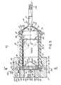
- the syringe and jacket assembly 30includes a hard plastic pressure jacket 31 , which may be of opaque or transparent material, a removable and replaceable disposable syringe 32 , which may be of opaque, transparent or semi-transparent material, and related structure hereinafter described.
- the syringe 32includes a syringe case 50 formed of a single piece of molded plastic material, a pressure cap 51 and a plunger 54 ( FIGS. 3A , 4 A- 5 ).
- the syringe case 50includes a cylindrical syringe body 55 having an open proximate end 56 and a remote end 58 to which is integrally formed a conical front wall 57 .
- the front wall 57is truncated at its forward end, to which is integrally formed an elongated neck 59 extending from the wall 57 at the center thereof.
- the neck 59 of the syringe case 50has an orifice 60 ( FIG.
- the rear end of the cavity 61is further defined by a forward facing conical surface 64 of the plunger 54 .
- the conical surface 64is of a slope which conforms to the slope of the interior of the conical front wall 57 .
- the plunger 54is slidable within the body 55 of the syringe case 50 such that the cavity 61 is of variable volume.
- a tubing connector 200has an internally threaded section 66 configured to mate with thread 63 on the exterior of tubing 65 .
- two or more threadsmay be on the exterior tubing 65 .
- ridges or knurls 215 and 225are best seen in FIG. 3C .
- the ridges or knurls 215 and 225thus achieve two benefits of increasing contact pressure and improving sealing, and reducing friction to make insertion and removal easier.
- the cap 51is generally conical in shape and has an inner rearward surface 75 , which conforms to the front surface of the conical wall 57 of the case 50 of the syringe 32 .
- the rearward conical surface 75 of the cap 51may be bonded to the front surface of the conical wall 57 of the case 50 of the syringe 32 , or it may be formed integrally therewith, molded from the same plastic material as the case 50 of the syringe 32 .
- the cap 51is separate from the syringe body portion 55 and has a pair of holes or detents 76 into which fit a pair of projections 77 extending forward from and formed integrally on the outer surface of the conical wall 57 of the case 50 of the syringe 32 .
- the cooperation of the pins or projections 77 with the holes or detents 76prevent the cap 51 from rotating with respect to the syringe case 50 when the cap 51 is mounted on the syringe 32 .
- the syringe 32includes structure that is configured to lock the syringe 32 to the front end of the jacket 31 by cooperating with mating structure on the jacket 31 .
- the jacket 31has, spaced around the circumference thereof near the remote or front end 35 of the jacket 31 , four equally spaced outwardly projecting thread sections 85 . These thread sections 85 are slightly less than 45° in extension around the circumference of the jacket 31 and are spaced apart with gaps of slightly greater than 45°.
- the cap 51has a cylindrical rim 87 in which are formed four similarly sized and spaced mating thread sections 86 . The thread sections 86 project inwardly toward the jacket 31 when the syringe 32 is positioned in the jacket 31 .
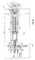
- the jaws 114are in alignment with the coupling 98 on the axes 40 and 41 of the jacket 32 and syringe 32 .
- the jaws 114may be in a retracted position at the center of the opening 39 of the door 25 adjacent to the proximate end 34 of the jacket 31 , and out of engagement with the coupling 96 on the plunger 54 .
- operation of the motor 101rotates the shaft 105 and drives the carriage 108 forwardly to move the jaws 114 toward and into engagement with the coupling 96 on the plunger 54 . This engagement takes place as shown in FIG.
- the coupling 96When a syringe 32 is inserted into the jacket 31 when the plunger 54 is at its rearmost position toward the proximate end 56 of the syringe body 55 , the coupling 96 is in a position adjacent the proximate end 56 of the syringe body 55 and projecting rearwardly therebeyond. When in such a position, engagement between the jaws 114 and the coupling 96 is brought about by translational movement between the position shown in FIG. 4A and that shown in FIG. 5 . In the unlocked or disengaged position shown in FIG.
- the axes 40 and 41 of the jacket 31 and the syringe 32 , respectively, as well as the center of the opening 39 of the door 25lie spaced from and parallel to the axis 112 of the shaft 105 as shown in FIG. 4A .
- the axis 112 of the shaft 105is slightly eccentric relative to the axes 40 and 41 of the jacket 31 and syringe 32 , respectively, as shown in FIG. 5 .
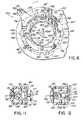
- the ring 127is moved among these three positions by a manually accessible handle 138 in the form of a cylindrical knob 139 rotatably attached to a lever arm 140 formed integrally and extending radially from the ring 127 through a slot 141 in the door 25 ( FIG. 1 ).
- the ring 127is retained in the recess 126 by a pair of screws 143 which thread into countersunk holes 144 at the periphery of the recess 126 in the back of the door 25 .
- These screws 143have enlarged heads 146 , which, when seated in the holes 144 , overlie the edge of the ring 127 , thereby securing it for rotatable movement within the recess 126 .
- the ring 127As shown in FIGS. 2 and 6 , the ring 127 , or rotatable cam, has an inner periphery 149 which is larger than the circumference of the body 55 of the syringe case 50 . Accordingly, when the syringe 32 is inserted in the jacket 31 , the proximate end 56 of the syringe case 50 extends through and is surrounded by the inner periphery 149 of the ring 127 (rotating cam).
- a key, or keyway, engaging structurein one embodiment, is in the form of four projections 251 , 252 , 253 and 254 ( FIGS. 4A , 4 B) provided in the edge of the proximal end 56 of the body 55 of the syringe case 50 . The four projections 251 - 254 are equally spaced.
- tabs or keys 155 , 156 and 157are Formed integrally of the ring 127 and projecting inwardly from the inner periphery 149 thereof.
- the tabs 155 - 157are unequally spaced around inner periphery 149 , such that the tabs or keys 155 , 156 and 157 fit between the respective projections 251 - 254 in the proximate end 56 of the body 55 of the syringe case 50 , so as to rotate the syringe 32 as the mechanism 125 is rotated through actuation of the handle 138 , or alternatively, to rotate the mechanism 125 as the syringe 32 is rotated at its end.
- any one of the spaces between projections 251 - 254may be engaged with the keys or tabs 155 - 157 of ring 127 .
- Thisallows the syringe 32 to be attached to the door 25 and pressure jacket 21 assembly in any one of four orientations as dictated by the four thread sections 85 of the cap 51 .
- the syringemay thus be retrofitted to the faceplates of the injectors described in U.S. Pat. No. 5,300,031; U.S. Pat. No. 5,451,211; and U.S. Pat. No. 5,658,261, incorporated herein in their entirety, since the tabs 155 - 157 in the ring 127 are compatibly positioned as compared to the injectors of these three patents.
- the rotation of the mechanism 125 from the unlocked position to the locked positionrotates the syringe 32 in the jacket 31 and rotates the cap such that its threads move from an unlocked position as shown in FIG. 4A to the locked position of FIG. 5 , to secure the cap to the jacket 31 by the engagement and tightening of the threads 85 and 86 .
- the translational movement of the axes 40 and 41 with respect to the axis 112is achieved by a fixed cylindrical cam follower or pin 150 which projects outwardly from the fixed housing portion 22 behind the ring 127 and into a cam slot 154 formed therein.
- the slot 154is shaped so that the axes 40 and 41 which remain fixed with respect to the ring 127 , along with the door 25 , the jacket 31 , the syringe 32 and all of the structure mutually carried thereby, are moved in relation to the axis 112 of the shaft 105 and the other structure mutually carried by the housing 22 , as the mechanism 125 is rotated.
- These axesmove toward and away from each other in accordance with the shape of the slot 154 determined by the radial distance from the point along the slot 154 where it engages the pin 150 to the axes 40 and 41 .
- the cam slot 154 in the ring 127is shaped such that, when the mechanism 125 is in the locked position as shown, for example, in FIGS. 6 and 7 , the distance between the pin 150 and the axes 40 and 41 is at a minimum and the axis 112 coincides with the axes 40 and 41 .
- FIGS. 5 and 7wherein the coupling 96 is shown positioned between the jaws 114 and in mutual engagement therewith.
- the pin 150is positioned at the open end 160 of the cam surface of the slot 154 so that the door 25 can be rotated upwardly about the hinge pin 26 , as shown in FIG. 9 , to open the space behind the door 25 for access thereto.
- This positionmay be used for cleaning the area behind the door 25 which is sometimes necessary because of possible leakage of fluid from the cavity 61 into the space behind the plunger 54 .
- Thiscan possibly occur because the fluid within the cavity 61 , when being injected by forward advancement of the plunger 54 , may be of relatively high pressure in the range, usually over 200 psi.
- pressuremay typically be in the range of from 25 to 300 psi, while in some injection applications the pressure may range to 1200 psi or higher.
- Leakage rearwardly along the exterior of the neck 59 of the syringe 32can cause fluid to flow between the body portion 55 of the syringe 32 and the jacket 31 .
- the cap 51is caused to fit snugly against the forward surface of the conical portion 57 of the syringe 32 at least sufficiently to restrict the flow of this leaking fluid onto the neck 59 .
- Thisis assisted by the configuration of the cap 51 at the rim 87 thereof so as to divert away from the space between the syringe 32 and jacket 31 fluid which might leak from the nozzle.
- the front of the housing 21has formed thereon a door stop 185 having a slot 186 formed therein for receiving a lug 187 of the door 25 , to restrain the door 25 against forward force exerted by the drive 100 .
- a magnetic sensor 188behind the front of the housing 21 adjacent the stop 185 is a magnetic sensor 188 , which is responsive to the presence of a magnet 189 in the ring 127 . The sensor 188 generates a signal to the control module 16 to activate the drive 100 only when the mechanism 125 is in its locked position.
- the locking structure between the syringe 32 and the pressure jacket 31should provide for retention of the syringe 32 in the jacket 31 against the force of the fluid pressure in the cavity 61 or axial force otherwise exerted on the plunger 54 by the drive 100 .
- This locking of the syringe 32 to the jacket 31is preferably achieved, as shown in FIG. 5 , by structure at or near the forward wall 57 of the syringe case 50 .
Landscapes
- Health & Medical Sciences (AREA)
- Vascular Medicine (AREA)
- Engineering & Computer Science (AREA)
- Anesthesiology (AREA)
- Biomedical Technology (AREA)
- Heart & Thoracic Surgery (AREA)
- Hematology (AREA)
- Life Sciences & Earth Sciences (AREA)
- Animal Behavior & Ethology (AREA)
- General Health & Medical Sciences (AREA)
- Public Health (AREA)
- Veterinary Medicine (AREA)
- Infusion, Injection, And Reservoir Apparatuses (AREA)
Abstract
Description
Claims (11)
Priority Applications (1)
| Application Number | Priority Date | Filing Date | Title |
|---|---|---|---|
| US12/108,007US8262644B2 (en) | 2004-11-17 | 2008-04-23 | Disposable front loadable syringe and injector |
Applications Claiming Priority (2)
| Application Number | Priority Date | Filing Date | Title |
|---|---|---|---|
| US10/990,587US20060106347A1 (en) | 2004-11-17 | 2004-11-17 | Disposable front loadable syringe and injector |
| US12/108,007US8262644B2 (en) | 2004-11-17 | 2008-04-23 | Disposable front loadable syringe and injector |
Related Parent Applications (1)
| Application Number | Title | Priority Date | Filing Date |
|---|---|---|---|
| US10/990,587DivisionUS20060106347A1 (en) | 2004-11-17 | 2004-11-17 | Disposable front loadable syringe and injector |
Publications (2)
| Publication Number | Publication Date |
|---|---|
| US20080208126A1 US20080208126A1 (en) | 2008-08-28 |
| US8262644B2true US8262644B2 (en) | 2012-09-11 |
Family
ID=35985421
Family Applications (4)
| Application Number | Title | Priority Date | Filing Date |
|---|---|---|---|
| US10/990,587AbandonedUS20060106347A1 (en) | 2004-11-17 | 2004-11-17 | Disposable front loadable syringe and injector |
| US11/577,099AbandonedUS20090024027A1 (en) | 2004-11-17 | 2005-11-17 | Tubing connector, front loadable syringe, and injector |
| US12/107,988Active2026-03-19US7998133B2 (en) | 2004-11-17 | 2008-04-23 | Disposable front loadable syringe and injector |
| US12/108,007Expired - LifetimeUS8262644B2 (en) | 2004-11-17 | 2008-04-23 | Disposable front loadable syringe and injector |
Family Applications Before (3)
| Application Number | Title | Priority Date | Filing Date |
|---|---|---|---|
| US10/990,587AbandonedUS20060106347A1 (en) | 2004-11-17 | 2004-11-17 | Disposable front loadable syringe and injector |
| US11/577,099AbandonedUS20090024027A1 (en) | 2004-11-17 | 2005-11-17 | Tubing connector, front loadable syringe, and injector |
| US12/107,988Active2026-03-19US7998133B2 (en) | 2004-11-17 | 2008-04-23 | Disposable front loadable syringe and injector |
Country Status (6)
| Country | Link |
|---|---|
| US (4) | US20060106347A1 (en) |
| EP (1) | EP1827535A2 (en) |
| JP (1) | JP2008520388A (en) |
| CN (1) | CN101068584B (en) |
| CA (1) | CA2587686A1 (en) |
| WO (1) | WO2006055952A2 (en) |
Cited By (7)
| Publication number | Priority date | Publication date | Assignee | Title |
|---|---|---|---|---|
| US9895290B2 (en) | 2013-05-16 | 2018-02-20 | Becton Dickinson and Company Ltd. | Mechanical friction enhancement for threaded connection incorporating opposing barb |
| US9968771B2 (en) | 2013-05-16 | 2018-05-15 | Becton Dickinson and Company Limited | Mechanical friction enhancement for threaded connection incorporating crushable ribs |
| US10098816B2 (en) | 2013-05-16 | 2018-10-16 | Becton Dickinson and Company Ltd. | Mechanical friction enhancement for threaded connection incorporating micro-threads |
| US10286152B2 (en) | 2012-09-28 | 2019-05-14 | Bayer Healthcare Llc | Quick release plunger |
| US10806852B2 (en) | 2014-03-19 | 2020-10-20 | Bayer Healthcare Llc | System for syringe engagement to an injector |
| US11998718B2 (en) | 2020-06-18 | 2024-06-04 | Bayer Healthcare Llc | System and method for syringe plunger engagement with an injector |
| USD1031029S1 (en) | 2003-11-25 | 2024-06-11 | Bayer Healthcare Llc | Syringe plunger |
Families Citing this family (22)
| Publication number | Priority date | Publication date | Assignee | Title |
|---|---|---|---|---|
| USD545967S1 (en)* | 2005-04-13 | 2007-07-03 | Medrad, Inc. | Fluid delivery apparatus |
| US8454560B2 (en)* | 2006-12-05 | 2013-06-04 | Mallinckrodt Llc | Syringe mount for a medical fluid injector |
| EP2158928A2 (en)* | 2007-04-11 | 2010-03-03 | Mallinckrodt Inc. | Universal syringe |
| EP2187996B1 (en)* | 2007-08-13 | 2011-10-12 | Mallinckrodt LLC | Drive ram for medical injectors |
| EP2185882B1 (en)* | 2007-09-13 | 2012-06-13 | Concast Ag | Injector for arc furnace |
| JP2010540089A (en)* | 2007-09-28 | 2010-12-24 | マリンクロッド・インコーポレイテッド | Connecting power head ram and power injector syringe |
| CN101868268B (en)* | 2007-11-20 | 2015-01-07 | 马林克罗特有限公司 | Power injector with ram retraction |
| US9078961B2 (en) | 2007-11-20 | 2015-07-14 | Liebel-Flarsheim Company Llc | Power injector with ram retraction |
| US7967785B2 (en)* | 2008-07-14 | 2011-06-28 | Nipro Healthcare Systems, Llc | Insulin reservoir detection via magnetic switching |
| USD708341S1 (en)* | 2009-04-30 | 2014-07-01 | Fujifilm Corporation | Medical work table |
| EP2456572B1 (en) | 2009-07-24 | 2014-02-26 | BAYER Medical Care Inc. | Multi-fluid medical injector system |
| EP2407103B1 (en)* | 2010-07-14 | 2013-11-27 | General Electric Company | Fluid connection for reducing a fluid volume in the connection |
| US9199033B1 (en) | 2014-10-28 | 2015-12-01 | Bayer Healthcare Llc | Self-orienting syringe and syringe interface |
| US10792418B2 (en) | 2014-10-28 | 2020-10-06 | Bayer Healthcare Llc | Self-orienting pressure jacket and pressure jacket-to-injector interface |
| NO2689315T3 (en) | 2014-10-28 | 2018-04-14 | ||
| WO2016069714A1 (en) | 2014-10-28 | 2016-05-06 | Bayer Healthcare Llc | Self-orienting pressure jacket and pressure jacket-to-injector interface |
| CA3003321C (en)* | 2015-10-28 | 2023-09-26 | Bayer Healthcare Llc | System and method for fluid injector engagement with a pressure jacket and syringe cap |
| WO2017083622A1 (en) | 2015-11-13 | 2017-05-18 | Bayer Healthcare Llc | Nested syringe assembly |
| US20180169326A1 (en)* | 2016-12-20 | 2018-06-21 | Liebel-Flarsheim Company Llc | Tapered front-load power injector syringe |
| CN107137803B (en)* | 2017-06-02 | 2023-04-18 | 南京巨鲨显示科技有限公司 | High-pressure injector needle cylinder rotation fixing device with plunger limiting function and method |
| US11191893B2 (en)* | 2018-01-31 | 2021-12-07 | Bayer Healthcare Llc | System and method for syringe engagement with injector |
| US11369735B2 (en)* | 2019-11-05 | 2022-06-28 | Insulet Corporation | Component positioning of a linear shuttle pump |
Citations (20)
| Publication number | Priority date | Publication date | Assignee | Title |
|---|---|---|---|---|
| US5047021A (en) | 1989-08-29 | 1991-09-10 | Utterberg David S | Male luer lock medical fitting |
| US5071413A (en)* | 1990-06-13 | 1991-12-10 | Utterberg David S | Universal connector |
| US5300031A (en) | 1991-06-07 | 1994-04-05 | Liebel-Flarsheim Company | Apparatus for injecting fluid into animals and disposable front loadable syringe therefor |
| US5383858A (en) | 1992-08-17 | 1995-01-24 | Medrad, Inc. | Front-loading medical injector and syringe for use therewith |
| US5535746A (en) | 1994-03-29 | 1996-07-16 | Sterling Winthrop Inc. | Prefilled syringe for use with power injector |
| US5860962A (en)* | 1997-12-08 | 1999-01-19 | Becton, Dickinson And Company | Shielded cannula for use with an I.V. site |
| US6017330A (en) | 1996-11-12 | 2000-01-25 | Medrad, Inc. | Plunger systems |
| US6027482A (en) | 1994-12-12 | 2000-02-22 | Becton Dickinson And Company | Syringe tip cap |
| US6200289B1 (en) | 1998-04-10 | 2001-03-13 | Milestone Scientific, Inc. | Pressure/force computer controlled drug delivery system and the like |
| US6368307B1 (en) | 1997-07-18 | 2002-04-09 | Liebel-Flarsheim Company | Front-loading power injector and method of loading flanged syringe therein |
| US6402718B1 (en) | 1992-08-17 | 2002-06-11 | Medrad, Inc. | Front-loading medical injector and syringe for use therewith |
| US6432089B1 (en) | 2000-06-21 | 2002-08-13 | Medrad, Inc. | Medical syringe |
| US6527742B1 (en) | 2001-11-14 | 2003-03-04 | Robert C. Malenchek | Safety syringe |
| WO2003095000A1 (en) | 2002-05-07 | 2003-11-20 | Medrad, Inc. | Syringe plungers, injectors, injector systems and methods for use in agitation of multi-component fluids |
| US6652489B2 (en) | 2000-02-07 | 2003-11-25 | Medrad, Inc. | Front-loading medical injector and syringes, syringe interfaces, syringe adapters and syringe plungers for use therewith |
| US20040064041A1 (en) | 2002-05-30 | 2004-04-01 | Lazzaro Frank A. | Front-loading medical injector and syringes, syringe interfaces, syringe adapters and syringe plungers for use therewith |
| US20040143224A1 (en) | 2002-01-07 | 2004-07-22 | Jeffrey Field | Method and apparatus for inhibiting fluid loss from a syringe |
| US20040142224A1 (en) | 2003-01-21 | 2004-07-22 | Abd Elhamid Mahmoud H. | Joining of bipolar plates in proton exchange membrane fuel cell stacks |
| US20050251096A1 (en) | 2004-05-10 | 2005-11-10 | George Armstrong | Syringe assembly with improved cap and luer connector |
| US20060058734A1 (en) | 2004-09-15 | 2006-03-16 | Phillips John C | Self-sealing male Luer connector with molded elastomeric tip |
- 2004
- 2004-11-17USUS10/990,587patent/US20060106347A1/ennot_activeAbandoned
- 2005
- 2005-11-17CACA002587686Apatent/CA2587686A1/ennot_activeAbandoned
- 2005-11-17EPEP05852008Apatent/EP1827535A2/ennot_activeWithdrawn
- 2005-11-17USUS11/577,099patent/US20090024027A1/ennot_activeAbandoned
- 2005-11-17JPJP2007543399Apatent/JP2008520388A/ennot_activeWithdrawn
- 2005-11-17CNCN2005800393230Apatent/CN101068584B/ennot_activeExpired - Fee Related
- 2005-11-17WOPCT/US2005/042313patent/WO2006055952A2/enactiveApplication Filing
- 2008
- 2008-04-23USUS12/107,988patent/US7998133B2/enactiveActive
- 2008-04-23USUS12/108,007patent/US8262644B2/ennot_activeExpired - Lifetime
Patent Citations (30)
| Publication number | Priority date | Publication date | Assignee | Title |
|---|---|---|---|---|
| US5047021A (en) | 1989-08-29 | 1991-09-10 | Utterberg David S | Male luer lock medical fitting |
| US5071413A (en)* | 1990-06-13 | 1991-12-10 | Utterberg David S | Universal connector |
| US5300031A (en) | 1991-06-07 | 1994-04-05 | Liebel-Flarsheim Company | Apparatus for injecting fluid into animals and disposable front loadable syringe therefor |
| US5738659A (en) | 1991-06-07 | 1998-04-14 | Liebel-Flarsheim Company | Method of injecting fluid into animals |
| US5451211A (en)* | 1991-06-07 | 1995-09-19 | Liebel-Flarsheim Company | Disposable front loadable syringe for power injector for injecting fluid into animals |
| US5658261A (en) | 1991-06-07 | 1997-08-19 | Liebel-Flarsheim Company | Disposable front loadable syringe |
| US5383858B1 (en) | 1992-08-17 | 1996-10-29 | Medrad Inc | Front-loading medical injector and syringe for use therewith |
| US5383858A (en) | 1992-08-17 | 1995-01-24 | Medrad, Inc. | Front-loading medical injector and syringe for use therewith |
| US6475192B1 (en) | 1992-08-17 | 2002-11-05 | Medrad, Inc. | System and method for providing information from a syringe to an injector |
| US5997502A (en) | 1992-08-17 | 1999-12-07 | Medrad, Inc. | Front loading medical injector and syringe for use therewith |
| US6402718B1 (en) | 1992-08-17 | 2002-06-11 | Medrad, Inc. | Front-loading medical injector and syringe for use therewith |
| US5535746A (en) | 1994-03-29 | 1996-07-16 | Sterling Winthrop Inc. | Prefilled syringe for use with power injector |
| US6027482A (en) | 1994-12-12 | 2000-02-22 | Becton Dickinson And Company | Syringe tip cap |
| US6017330A (en) | 1996-11-12 | 2000-01-25 | Medrad, Inc. | Plunger systems |
| US6368307B1 (en) | 1997-07-18 | 2002-04-09 | Liebel-Flarsheim Company | Front-loading power injector and method of loading flanged syringe therein |
| US5860962A (en)* | 1997-12-08 | 1999-01-19 | Becton, Dickinson And Company | Shielded cannula for use with an I.V. site |
| US6200289B1 (en) | 1998-04-10 | 2001-03-13 | Milestone Scientific, Inc. | Pressure/force computer controlled drug delivery system and the like |
| US20040133162A1 (en) | 2000-02-07 | 2004-07-08 | Mark Trocki | Front-loading medical injector adapted to releasably engage a syringe regardless of the orientation of the syringe with respect to the injector |
| US20040133161A1 (en) | 2000-02-07 | 2004-07-08 | Mark Trocki | Front-loading syringe adapted to releasably engage a medical injector regardless of the orientation of the syringe with respect to the injector |
| US6652489B2 (en) | 2000-02-07 | 2003-11-25 | Medrad, Inc. | Front-loading medical injector and syringes, syringe interfaces, syringe adapters and syringe plungers for use therewith |
| US20040133153A1 (en) | 2000-02-07 | 2004-07-08 | Mark Trocki | Syringe adapter for use with a medical injector and method for adapting an injector |
| US20040116861A1 (en) | 2000-02-07 | 2004-06-17 | Mark Trocki | Front-loading injector system including a syringe and an injector having a drive piston adapted to connectively engage the syringe plunger |
| US6432089B1 (en) | 2000-06-21 | 2002-08-13 | Medrad, Inc. | Medical syringe |
| US6527742B1 (en) | 2001-11-14 | 2003-03-04 | Robert C. Malenchek | Safety syringe |
| US20040143224A1 (en) | 2002-01-07 | 2004-07-22 | Jeffrey Field | Method and apparatus for inhibiting fluid loss from a syringe |
| WO2003095000A1 (en) | 2002-05-07 | 2003-11-20 | Medrad, Inc. | Syringe plungers, injectors, injector systems and methods for use in agitation of multi-component fluids |
| US20040064041A1 (en) | 2002-05-30 | 2004-04-01 | Lazzaro Frank A. | Front-loading medical injector and syringes, syringe interfaces, syringe adapters and syringe plungers for use therewith |
| US20040142224A1 (en) | 2003-01-21 | 2004-07-22 | Abd Elhamid Mahmoud H. | Joining of bipolar plates in proton exchange membrane fuel cell stacks |
| US20050251096A1 (en) | 2004-05-10 | 2005-11-10 | George Armstrong | Syringe assembly with improved cap and luer connector |
| US20060058734A1 (en) | 2004-09-15 | 2006-03-16 | Phillips John C | Self-sealing male Luer connector with molded elastomeric tip |
Non-Patent Citations (3)
| Title |
|---|
| International Search Report, Corresponding Application No. PCT/US2005/042313, Mailed May 23, 2006. |
| ISO 594-2: "Conical Fittings with a 6% (Luer) Taper for Syringes, Needles and Certain other Medical Equipment-Part 2: Lock Fittings"; May 1, 1991, IDS-594-2, pp. I-II, 1, XP000826443 abstract; Figures 1-2. |
| ISO 594-2: "Conical Fittings with a 6% (Luer) Taper for Syringes, Needles and Certain other Medical Equipment—Part 2: Lock Fittings"; May 1, 1991, IDS-594-2, pp. I-II, 1, XP000826443 abstract; Figures 1-2. |
Cited By (12)
| Publication number | Priority date | Publication date | Assignee | Title |
|---|---|---|---|---|
| USD1031029S1 (en) | 2003-11-25 | 2024-06-11 | Bayer Healthcare Llc | Syringe plunger |
| US10286152B2 (en) | 2012-09-28 | 2019-05-14 | Bayer Healthcare Llc | Quick release plunger |
| US9895290B2 (en) | 2013-05-16 | 2018-02-20 | Becton Dickinson and Company Ltd. | Mechanical friction enhancement for threaded connection incorporating opposing barb |
| US9968771B2 (en) | 2013-05-16 | 2018-05-15 | Becton Dickinson and Company Limited | Mechanical friction enhancement for threaded connection incorporating crushable ribs |
| US10098816B2 (en) | 2013-05-16 | 2018-10-16 | Becton Dickinson and Company Ltd. | Mechanical friction enhancement for threaded connection incorporating micro-threads |
| US10518077B2 (en) | 2013-05-16 | 2019-12-31 | Becton Dickinson and Company Limited | Mechanical friction enhancement for threaded connection incorporating crushable ribs |
| US10898412B2 (en) | 2013-05-16 | 2021-01-26 | Becton Dickinson and Company, Ltd. | Mechanical friction enhancement for threaded connection incorporating micro-threads |
| US11701508B2 (en) | 2013-05-16 | 2023-07-18 | Becton Dickinson and Company Limited | Mechanical friction enhancement for threaded connection incorporating crushable ribs |
| US10806852B2 (en) | 2014-03-19 | 2020-10-20 | Bayer Healthcare Llc | System for syringe engagement to an injector |
| US11103637B2 (en) | 2014-03-19 | 2021-08-31 | Bayer Healthcare Llc | System for syringe engagement to an injector |
| US11383029B2 (en) | 2014-03-19 | 2022-07-12 | Bayer Healthcare Llc | System for syringe engagement to an injector |
| US11998718B2 (en) | 2020-06-18 | 2024-06-04 | Bayer Healthcare Llc | System and method for syringe plunger engagement with an injector |
Also Published As
| Publication number | Publication date |
|---|---|
| CN101068584B (en) | 2010-09-01 |
| US20090024027A1 (en) | 2009-01-22 |
| US20080215007A1 (en) | 2008-09-04 |
| US20080208126A1 (en) | 2008-08-28 |
| WO2006055952A3 (en) | 2006-07-13 |
| US20060106347A1 (en) | 2006-05-18 |
| EP1827535A2 (en) | 2007-09-05 |
| JP2008520388A (en) | 2008-06-19 |
| CN101068584A (en) | 2007-11-07 |
| US7998133B2 (en) | 2011-08-16 |
| WO2006055952A2 (en) | 2006-05-26 |
| CA2587686A1 (en) | 2006-05-26 |
Similar Documents
| Publication | Publication Date | Title |
|---|---|---|
| US8262644B2 (en) | Disposable front loadable syringe and injector | |
| US7081104B2 (en) | Method and apparatus for injecting fluid into animals and disposable front loadable syringe therefor | |
| JP5509232B2 (en) | Universal adapter for syringe plunger | |
| US6716195B2 (en) | Syringe adapters for use with an injector | |
| US6368307B1 (en) | Front-loading power injector and method of loading flanged syringe therein | |
| US20180169326A1 (en) | Tapered front-load power injector syringe |
Legal Events
| Date | Code | Title | Description |
|---|---|---|---|
| AS | Assignment | Owner name:MALLINCKRODT LLC, MISSOURI Free format text:CHANGE OF LEGAL ENTITY;ASSIGNOR:MALLINCKRODT INC.;REEL/FRAME:026754/0001 Effective date:20110623 | |
| STCF | Information on status: patent grant | Free format text:PATENTED CASE | |
| AS | Assignment | Owner name:DEUTSCHE BANK AG NEW YORK BRANCH, NEW YORK Free format text:SECURITY INTEREST;ASSIGNORS:MALLINCKRODT INTERNATIONAL FINANCE S.A.;MALLINCKRODT CB LLC;MALLINCKRODT FINANCE GMBH;AND OTHERS;REEL/FRAME:032480/0001 Effective date:20140319 | |
| AS | Assignment | Owner name:LIEBEL-FLARSHEIM COMPANY, OHIO Free format text:ASSIGNMENT OF ASSIGNORS INTEREST;ASSIGNORS:FAGO, FRANK M.;LEWIS, FRANK M.;REEL/FRAME:032503/0971 Effective date:20041112 Owner name:LIEBEL-FLARSHEIM COMPANY LLC, MISSOURI Free format text:CHANGE OF LEGAL ENTITY;ASSIGNOR:LIEBEL-FLARSHEIM COMPANY;REEL/FRAME:032504/0212 Effective date:20110623 | |
| AS | Assignment | Owner name:LIEBEL-FLARSHEIM COMPANY LLC, OHIO Free format text:RELEASE BY SECURED PARTY;ASSIGNOR:DEUTSCHE BANK AG NEW YORK BRANCH, AS COLLATERAL AGENT;REEL/FRAME:037172/0094 Effective date:20151127 | |
| FPAY | Fee payment | Year of fee payment:4 | |
| MAFP | Maintenance fee payment | Free format text:PAYMENT OF MAINTENANCE FEE, 8TH YEAR, LARGE ENTITY (ORIGINAL EVENT CODE: M1552); ENTITY STATUS OF PATENT OWNER: LARGE ENTITY Year of fee payment:8 | |
| AS | Assignment | Owner name:INO THERAPEUTICS LLC, MISSOURI Free format text:RELEASE OF PATENT SECURITY INTERESTS RECORDED AT REEL 032480, FRAME 0001;ASSIGNOR:DEUTSCHE BANK AG NEW YORK BRANCH, AS COLLATERAL AGENT;REEL/FRAME:065609/0322 Effective date:20231114 Owner name:IKARIA THERAPEUTICS LLC, NEW JERSEY Free format text:RELEASE OF PATENT SECURITY INTERESTS RECORDED AT REEL 032480, FRAME 0001;ASSIGNOR:DEUTSCHE BANK AG NEW YORK BRANCH, AS COLLATERAL AGENT;REEL/FRAME:065609/0322 Effective date:20231114 Owner name:THERAKOS, INC., MISSOURI Free format text:RELEASE OF PATENT SECURITY INTERESTS RECORDED AT REEL 032480, FRAME 0001;ASSIGNOR:DEUTSCHE BANK AG NEW YORK BRANCH, AS COLLATERAL AGENT;REEL/FRAME:065609/0322 Effective date:20231114 Owner name:ST SHARED SERVICES LLC, MISSOURI Free format text:RELEASE OF PATENT SECURITY INTERESTS RECORDED AT REEL 032480, FRAME 0001;ASSIGNOR:DEUTSCHE BANK AG NEW YORK BRANCH, AS COLLATERAL AGENT;REEL/FRAME:065609/0322 Effective date:20231114 Owner name:INFACARE PHARMACEUTICAL CORPORATION, MISSOURI Free format text:RELEASE OF PATENT SECURITY INTERESTS RECORDED AT REEL 032480, FRAME 0001;ASSIGNOR:DEUTSCHE BANK AG NEW YORK BRANCH, AS COLLATERAL AGENT;REEL/FRAME:065609/0322 Effective date:20231114 Owner name:MALLINCKRODT PHARMA IP TRADING UNLIMITED COMPANY (F/K/A MALLINCKRODT PHARMA IP TRADING D.A.C.), IRELAND Free format text:RELEASE OF PATENT SECURITY INTERESTS RECORDED AT REEL 032480, FRAME 0001;ASSIGNOR:DEUTSCHE BANK AG NEW YORK BRANCH, AS COLLATERAL AGENT;REEL/FRAME:065609/0322 Effective date:20231114 Owner name:MALLINCKRODT PHARMACEUTICALS IRELAND LIMITED, IRELAND Free format text:RELEASE OF PATENT SECURITY INTERESTS RECORDED AT REEL 032480, FRAME 0001;ASSIGNOR:DEUTSCHE BANK AG NEW YORK BRANCH, AS COLLATERAL AGENT;REEL/FRAME:065609/0322 Effective date:20231114 Owner name:VTESSE LLC (F/K/A VTESSE INC.), MISSOURI Free format text:RELEASE OF PATENT SECURITY INTERESTS RECORDED AT REEL 032480, FRAME 0001;ASSIGNOR:DEUTSCHE BANK AG NEW YORK BRANCH, AS COLLATERAL AGENT;REEL/FRAME:065609/0322 Effective date:20231114 Owner name:SUCAMPO PHARMA AMERICAS LLC, MISSOURI Free format text:RELEASE OF PATENT SECURITY INTERESTS RECORDED AT REEL 032480, FRAME 0001;ASSIGNOR:DEUTSCHE BANK AG NEW YORK BRANCH, AS COLLATERAL AGENT;REEL/FRAME:065609/0322 Effective date:20231114 Owner name:STRATATECH CORPORATION, WISCONSIN Free format text:RELEASE OF PATENT SECURITY INTERESTS RECORDED AT REEL 032480, FRAME 0001;ASSIGNOR:DEUTSCHE BANK AG NEW YORK BRANCH, AS COLLATERAL AGENT;REEL/FRAME:065609/0322 Effective date:20231114 Owner name:SPECGX LLC, MISSOURI Free format text:RELEASE OF PATENT SECURITY INTERESTS RECORDED AT REEL 032480, FRAME 0001;ASSIGNOR:DEUTSCHE BANK AG NEW YORK BRANCH, AS COLLATERAL AGENT;REEL/FRAME:065609/0322 Effective date:20231114 Owner name:OCERA THERAPEUTICS LLC (F/K/A OCERA THERAPEUTICS, INC.), MISSOURI Free format text:RELEASE OF PATENT SECURITY INTERESTS RECORDED AT REEL 032480, FRAME 0001;ASSIGNOR:DEUTSCHE BANK AG NEW YORK BRANCH, AS COLLATERAL AGENT;REEL/FRAME:065609/0322 Effective date:20231114 Owner name:MALLINCKRODT ARD IP UNLIMITED COMPANY (F/K/A MALLINCKRODT ARD IP LIMITED), IRELAND Free format text:RELEASE OF PATENT SECURITY INTERESTS RECORDED AT REEL 032480, FRAME 0001;ASSIGNOR:DEUTSCHE BANK AG NEW YORK BRANCH, AS COLLATERAL AGENT;REEL/FRAME:065609/0322 Effective date:20231114 Owner name:MALLINCKRODT HOSPITAL PRODUCTS IP UNLIMITED COMPANY (F/K/A MALLINCKRODT HOSPITAL PRODUCTS IP LIMITED), IRELAND Free format text:RELEASE OF PATENT SECURITY INTERESTS RECORDED AT REEL 032480, FRAME 0001;ASSIGNOR:DEUTSCHE BANK AG NEW YORK BRANCH, AS COLLATERAL AGENT;REEL/FRAME:065609/0322 Effective date:20231114 Owner name:MEH, INC., MISSOURI Free format text:RELEASE OF PATENT SECURITY INTERESTS RECORDED AT REEL 032480, FRAME 0001;ASSIGNOR:DEUTSCHE BANK AG NEW YORK BRANCH, AS COLLATERAL AGENT;REEL/FRAME:065609/0322 Effective date:20231114 Owner name:IMC EXPLORATION COMPANY, MISSOURI Free format text:RELEASE OF PATENT SECURITY INTERESTS RECORDED AT REEL 032480, FRAME 0001;ASSIGNOR:DEUTSCHE BANK AG NEW YORK BRANCH, AS COLLATERAL AGENT;REEL/FRAME:065609/0322 Effective date:20231114 Owner name:MALLINCKRODT US HOLDINGS LLC, MISSOURI Free format text:RELEASE OF PATENT SECURITY INTERESTS RECORDED AT REEL 032480, FRAME 0001;ASSIGNOR:DEUTSCHE BANK AG NEW YORK BRANCH, AS COLLATERAL AGENT;REEL/FRAME:065609/0322 Effective date:20231114 Owner name:MALLINCKRODT VETERINARY, INC., MISSOURI Free format text:RELEASE OF PATENT SECURITY INTERESTS RECORDED AT REEL 032480, FRAME 0001;ASSIGNOR:DEUTSCHE BANK AG NEW YORK BRANCH, AS COLLATERAL AGENT;REEL/FRAME:065609/0322 Effective date:20231114 Owner name:MALLINCKRODT BRAND PHARMACEUTICALS LLC (F/K/A MALLINCKRODT BRAND PHARMACEUTICALS, INC.), MISSOURI Free format text:RELEASE OF PATENT SECURITY INTERESTS RECORDED AT REEL 032480, FRAME 0001;ASSIGNOR:DEUTSCHE BANK AG NEW YORK BRANCH, AS COLLATERAL AGENT;REEL/FRAME:065609/0322 Effective date:20231114 Owner name:LIEBEL-FLARSHEIM COMPANY LLC, MISSOURI Free format text:RELEASE OF PATENT SECURITY INTERESTS RECORDED AT REEL 032480, FRAME 0001;ASSIGNOR:DEUTSCHE BANK AG NEW YORK BRANCH, AS COLLATERAL AGENT;REEL/FRAME:065609/0322 Effective date:20231114 Owner name:LAFAYETTE PHARMACEUTICALS LLC, MISSOURI Free format text:RELEASE OF PATENT SECURITY INTERESTS RECORDED AT REEL 032480, FRAME 0001;ASSIGNOR:DEUTSCHE BANK AG NEW YORK BRANCH, AS COLLATERAL AGENT;REEL/FRAME:065609/0322 Effective date:20231114 Owner name:MALLINCKRODT LLC, MISSOURI Free format text:RELEASE OF PATENT SECURITY INTERESTS RECORDED AT REEL 032480, FRAME 0001;ASSIGNOR:DEUTSCHE BANK AG NEW YORK BRANCH, AS COLLATERAL AGENT;REEL/FRAME:065609/0322 Effective date:20231114 Owner name:MALLINCKRODT ENTERPRISES LLC, MISSOURI Free format text:RELEASE OF PATENT SECURITY INTERESTS RECORDED AT REEL 032480, FRAME 0001;ASSIGNOR:DEUTSCHE BANK AG NEW YORK BRANCH, AS COLLATERAL AGENT;REEL/FRAME:065609/0322 Effective date:20231114 Owner name:MALLINCKRODT ENTERPRISES HOLDINGS LLC (F/K/A MALLINCKRODT ENTERPRISES HOLDINGS, INC.), MISSOURI Free format text:RELEASE OF PATENT SECURITY INTERESTS RECORDED AT REEL 032480, FRAME 0001;ASSIGNOR:DEUTSCHE BANK AG NEW YORK BRANCH, AS COLLATERAL AGENT;REEL/FRAME:065609/0322 Effective date:20231114 Owner name:CNS THERAPEUTICS, INC., MISSOURI Free format text:RELEASE OF PATENT SECURITY INTERESTS RECORDED AT REEL 032480, FRAME 0001;ASSIGNOR:DEUTSCHE BANK AG NEW YORK BRANCH, AS COLLATERAL AGENT;REEL/FRAME:065609/0322 Effective date:20231114 Owner name:LUDLOW LLC (F/K/A LUDLOW CORPORATION), MISSOURI Free format text:RELEASE OF PATENT SECURITY INTERESTS RECORDED AT REEL 032480, FRAME 0001;ASSIGNOR:DEUTSCHE BANK AG NEW YORK BRANCH, AS COLLATERAL AGENT;REEL/FRAME:065609/0322 Effective date:20231114 Owner name:MNK 2011 LLC (F/K/A MALLINCKRODT INC.), MISSOURI Free format text:RELEASE OF PATENT SECURITY INTERESTS RECORDED AT REEL 032480, FRAME 0001;ASSIGNOR:DEUTSCHE BANK AG NEW YORK BRANCH, AS COLLATERAL AGENT;REEL/FRAME:065609/0322 Effective date:20231114 Owner name:MALLINCKRODT US POOL LLC, MISSOURI Free format text:RELEASE OF PATENT SECURITY INTERESTS RECORDED AT REEL 032480, FRAME 0001;ASSIGNOR:DEUTSCHE BANK AG NEW YORK BRANCH, AS COLLATERAL AGENT;REEL/FRAME:065609/0322 Effective date:20231114 Owner name:MALLINCKRODT CARRIBEAN, INC., MISSOURI Free format text:RELEASE OF PATENT SECURITY INTERESTS RECORDED AT REEL 032480, FRAME 0001;ASSIGNOR:DEUTSCHE BANK AG NEW YORK BRANCH, AS COLLATERAL AGENT;REEL/FRAME:065609/0322 Effective date:20231114 Owner name:MALLINCKRODT US HOLDINGS LLC (F/K/A MALLINCKRODT US HOLDINGS INC.), MISSOURI Free format text:RELEASE OF PATENT SECURITY INTERESTS RECORDED AT REEL 032480, FRAME 0001;ASSIGNOR:DEUTSCHE BANK AG NEW YORK BRANCH, AS COLLATERAL AGENT;REEL/FRAME:065609/0322 Effective date:20231114 Owner name:MALLINCKRODT FINANCE GMBH, SWITZERLAND Free format text:RELEASE OF PATENT SECURITY INTERESTS RECORDED AT REEL 032480, FRAME 0001;ASSIGNOR:DEUTSCHE BANK AG NEW YORK BRANCH, AS COLLATERAL AGENT;REEL/FRAME:065609/0322 Effective date:20231114 Owner name:MALLINCKRODT CB LLC, MISSOURI Free format text:RELEASE OF PATENT SECURITY INTERESTS RECORDED AT REEL 032480, FRAME 0001;ASSIGNOR:DEUTSCHE BANK AG NEW YORK BRANCH, AS COLLATERAL AGENT;REEL/FRAME:065609/0322 Effective date:20231114 Owner name:MALLINCKRODT INTERNATIONAL FINANCE S.A., LUXEMBOURG Free format text:RELEASE OF PATENT SECURITY INTERESTS RECORDED AT REEL 032480, FRAME 0001;ASSIGNOR:DEUTSCHE BANK AG NEW YORK BRANCH, AS COLLATERAL AGENT;REEL/FRAME:065609/0322 Effective date:20231114 | |
| MAFP | Maintenance fee payment | Free format text:PAYMENT OF MAINTENANCE FEE, 12TH YEAR, LARGE ENTITY (ORIGINAL EVENT CODE: M1553); ENTITY STATUS OF PATENT OWNER: LARGE ENTITY Year of fee payment:12 |