US8262618B2 - System consisting of an insertion head and an inserter - Google Patents
System consisting of an insertion head and an inserterDownload PDFInfo
- Publication number
- US8262618B2 US8262618B2US12/048,591US4859108AUS8262618B2US 8262618 B2US8262618 B2US 8262618B2US 4859108 AUS4859108 AUS 4859108AUS 8262618 B2US8262618 B2US 8262618B2
- Authority
- US
- United States
- Prior art keywords
- inserter
- insertion head
- base
- joint
- activating member
- Prior art date
- Legal status (The legal status is an assumption and is not a legal conclusion. Google has not performed a legal analysis and makes no representation as to the accuracy of the status listed.)
- Expired - Fee Related, expires
Links
Images


Classifications
- A—HUMAN NECESSITIES
- A61—MEDICAL OR VETERINARY SCIENCE; HYGIENE
- A61M—DEVICES FOR INTRODUCING MEDIA INTO, OR ONTO, THE BODY; DEVICES FOR TRANSDUCING BODY MEDIA OR FOR TAKING MEDIA FROM THE BODY; DEVICES FOR PRODUCING OR ENDING SLEEP OR STUPOR
- A61M5/00—Devices for bringing media into the body in a subcutaneous, intra-vascular or intramuscular way; Accessories therefor, e.g. filling or cleaning devices, arm-rests
- A61M5/14—Infusion devices, e.g. infusing by gravity; Blood infusion; Accessories therefor
- A61M5/158—Needles for infusions; Accessories therefor, e.g. for inserting infusion needles, or for holding them on the body
- A—HUMAN NECESSITIES
- A61—MEDICAL OR VETERINARY SCIENCE; HYGIENE
- A61M—DEVICES FOR INTRODUCING MEDIA INTO, OR ONTO, THE BODY; DEVICES FOR TRANSDUCING BODY MEDIA OR FOR TAKING MEDIA FROM THE BODY; DEVICES FOR PRODUCING OR ENDING SLEEP OR STUPOR
- A61M25/00—Catheters; Hollow probes
- A61M25/01—Introducing, guiding, advancing, emplacing or holding catheters
- A61M25/06—Body-piercing guide needles or the like
- A61M25/0612—Devices for protecting the needle; Devices to help insertion of the needle, e.g. wings or holders
- A—HUMAN NECESSITIES
- A61—MEDICAL OR VETERINARY SCIENCE; HYGIENE
- A61M—DEVICES FOR INTRODUCING MEDIA INTO, OR ONTO, THE BODY; DEVICES FOR TRANSDUCING BODY MEDIA OR FOR TAKING MEDIA FROM THE BODY; DEVICES FOR PRODUCING OR ENDING SLEEP OR STUPOR
- A61M5/00—Devices for bringing media into the body in a subcutaneous, intra-vascular or intramuscular way; Accessories therefor, e.g. filling or cleaning devices, arm-rests
- A61M5/14—Infusion devices, e.g. infusing by gravity; Blood infusion; Accessories therefor
- A61M5/158—Needles for infusions; Accessories therefor, e.g. for inserting infusion needles, or for holding them on the body
- A61M2005/1581—Right-angle needle-type devices
- A—HUMAN NECESSITIES
- A61—MEDICAL OR VETERINARY SCIENCE; HYGIENE
- A61M—DEVICES FOR INTRODUCING MEDIA INTO, OR ONTO, THE BODY; DEVICES FOR TRANSDUCING BODY MEDIA OR FOR TAKING MEDIA FROM THE BODY; DEVICES FOR PRODUCING OR ENDING SLEEP OR STUPOR
- A61M5/00—Devices for bringing media into the body in a subcutaneous, intra-vascular or intramuscular way; Accessories therefor, e.g. filling or cleaning devices, arm-rests
- A61M5/14—Infusion devices, e.g. infusing by gravity; Blood infusion; Accessories therefor
- A61M5/158—Needles for infusions; Accessories therefor, e.g. for inserting infusion needles, or for holding them on the body
- A61M2005/1585—Needle inserters
- A—HUMAN NECESSITIES
- A61—MEDICAL OR VETERINARY SCIENCE; HYGIENE
- A61M—DEVICES FOR INTRODUCING MEDIA INTO, OR ONTO, THE BODY; DEVICES FOR TRANSDUCING BODY MEDIA OR FOR TAKING MEDIA FROM THE BODY; DEVICES FOR PRODUCING OR ENDING SLEEP OR STUPOR
- A61M5/00—Devices for bringing media into the body in a subcutaneous, intra-vascular or intramuscular way; Accessories therefor, e.g. filling or cleaning devices, arm-rests
- A61M5/14—Infusion devices, e.g. infusing by gravity; Blood infusion; Accessories therefor
- A61M5/158—Needles for infusions; Accessories therefor, e.g. for inserting infusion needles, or for holding them on the body
- A61M2005/1587—Needles for infusions; Accessories therefor, e.g. for inserting infusion needles, or for holding them on the body suitable for being connected to an infusion line after insertion into a patient
- A—HUMAN NECESSITIES
- A61—MEDICAL OR VETERINARY SCIENCE; HYGIENE
- A61M—DEVICES FOR INTRODUCING MEDIA INTO, OR ONTO, THE BODY; DEVICES FOR TRANSDUCING BODY MEDIA OR FOR TAKING MEDIA FROM THE BODY; DEVICES FOR PRODUCING OR ENDING SLEEP OR STUPOR
- A61M5/00—Devices for bringing media into the body in a subcutaneous, intra-vascular or intramuscular way; Accessories therefor, e.g. filling or cleaning devices, arm-rests
- A61M5/178—Syringes
- A61M5/31—Details
- A61M5/32—Needles; Details of needles pertaining to their connection with syringe or hub; Accessories for bringing the needle into, or holding the needle on, the body; Devices for protection of needles
- A61M5/3205—Apparatus for removing or disposing of used needles or syringes, e.g. containers; Means for protection against accidental injuries from used needles
- A61M5/321—Means for protection against accidental injuries by used needles
- A61M5/3216—Caps placed transversally onto the needle, e.g. pivotally attached to the needle base
Definitions
- the present inventionrelates to devices for the delivery, administration and passage of medicament and other fluids and methods and uses thereof.
- the inventionrelates to a system consisting of an insertion head for medical or pharmaceutical applications and an inserter for automatically positioning the insertion head on an organic tissue, such as human skin.
- the insertion headmay be part of an infusion set for administering a medicine.
- An insertion headis known from DE 198 21 723 C1 which comprises a base including an insertion means which projects on the lower side of the base.
- the insertion meansis formed as a flexible cannula.
- An injection needlestabilizes the insertion means while it is inserted into a patient's tissue.
- a needle protectionis detachably fastened to the base as a protection against pricking injuries. The needle protection is also awkward to remove.
- the insertion means which projects from the lower side, together with the injection needle, and the needle protectionalso considerably enlarge the packaging volume of the insertion head.
- Inserting the insertion means into the tissuecan also evoke emotional barriers in the user. For some users, even the sight of the injection needle arouses aversions. Such users are correspondingly uncertain when positioning the insertion head on the tissue. In order to avoid such aversions and consequent uncertainty in handling, which can cause the insertion head to be incorrectly operated, inserters have been developed with the aid of which the insertion heads can be automatically positioned on the tissue. An example of such an inserter is known from DE 203 20 207 U1.
- the disadvantages mentionedare eliminated by the insertion means being movably mounted by the base.
- the insertion meansassumes a protective position for storage, transport and handling up until being inserted into the tissue. In order to be inserted, it can be moved from the protective position into an insertion position.
- a pivoting mobilityis disclosed as a type of movement.
- the insertion headmay have a compact construction when the insertion means assumes the protective position, and there is no longer any danger of injury in the protective position, however in order to be inserted into the tissue, the insertion means does have to be moved into the insertion position and positioned on the tissue.
- the insertion head and an inserter system of the present inventionincludes insertion head having a base including a lower side or contact area, which can be positioned on the tissue, and an insertion means, which is movably mounted by the base.
- the insertion meansmay be moved relative to the base from a protective position in which at least a free end of the insertion means is short of the lower side of the base, into an insertion position in which the free end protrudes beyond the lower side and can penetrate into the tissue.
- the inserterincludes an inserter casing, a holding means for holding the insertion head in an initial position and a drive. On a lower side, which faces the tissue when the insertion head is positioned, the inserter casing comprises a passage opening for the insertion head.
- the holding meansmay be coupled, e.g., rigidly connected, movably or fixedly to the inserter casing.
- the holding meansmay hold the insertion head in the initial position such that the lower side of the insertion head and the lower side of the inserter casing point in the same direction.
- the driveis arranged such that it can move the insertion head out of the initial position in an advancing direction which points through the opening in the inserter casing.
- the drivemay form the holding means by holding the insertion head during the movement until it is positioned on the tissue or over most of this movement and releasing the insertion head at the end of this movement or after the insertion head has been positioned on the tissue.
- the holding means and the drivemay be separate from each other, and the insertion head may be released at the beginning of its movement out of a holding engagement in which the holding means holds it in the initial position.
- the insertermay include an activating member movable relative to the holding means and operable by the user.
- the activating membermay initiate movement of the insertion means into the insertion position.
- the activating membermay initiate movement of the insertion head in its initial position relative to the inserter casing and in a holding engagement with the holding means, i.e. when it is at rest.
- the insertion headmay be actuated while the drive moves the insertion head in the advancing direction.
- the activating membermay form a trigger of the inserter to trigger the drive to move the insertion head towards the tissue.
- a suitable sequence controllermay control the operation of the inserter such that that the insertion head is activated in a first step, i.e. by transferring the insertion means into the insertion position, and the movement of the insertion head triggered in a subsequent step.
- the activating membermay be responsible for activating the insertion head
- a triggere.g., a triggering button, may be provided on the inserter for triggering.
- the presently described systemthus provides an insertion head with a movable insertion means and automatic positioning of the insertion head on the tissue.
- the activating member and the insertion meansmay be connected or coupled to each other by means of a coupling.
- coupling between the activating member to the insertion meansis a joint having two joint elements in an engagement or brought into an engagement with each other automatically when the insertion head is situated in its initial position, or during its movement.
- the jointmay be a cam joint such that one of the joint elements is a guiding cam and the other is an engaging element which is guided on the guiding cam.
- the activating membermay form one of the joint elements or may cooperate with one or more of the joint elements.
- the jointmay also be arranged as a screw joint or as a toothed engagement between two toothed wheels or between a toothed wheel and a toothed rod. It will be understood that the cam coupling may comprise a variety of configurations and may convert the movement of one joint element into the movement of the other.
- one of the joint elementsmay be moved relative to the other and relative to the inserter casing, in or counter to the advancing direction of the insertion head.
- its guiding camexhibits an inclination with respect to the advancing direction.
- the engaging elementmay be moved transverse to the advancing direction.
- the inclination of the guiding cammay be constant, such that a linear guiding cam is obtained.
- the inclinationmay also be variable and the guiding cam can for example be curved.
- the activating membermay be configured to act on a receiving member of the insertion head movably mounted by the base of the insertion head.
- the receiving membermay coupleed to the insertion means rigidly or in a joint, such that when the receiving member moves relative to the base, the insertion means is moved into the insertion position.
- the activating membermay cooperate with the receiving member via or in the joint.
- a jointmay not be provided and the coupling between the activating member and the receiving member may be a pressing contact such that the receiving member or draws on the receiving member and slaves the receiving member.
- the coupling between the activating member and the insertion meanscomprises a loose, i.e. pressing contact.
- the two members situated in the pressing contactmay each form a contact area for the pressing contact.
- a pressing contactmay simplify the mechanism and facilitates releasing the insertion head and inserting a new insertion head.
- the two contact areas for the pressing contactmay form the interface between the insertion head and the inserter.
- the receiving member of the insertion headforms one of the contact areas.
- the other contact areamay be arranged directly on the activating member or on an effector member via which the activating member acts on the insertion means.
- the joint contained in the coupling between the activating member and the insertion meansmay be provided by the insertion head, for example between the receiving member and the insertion means.
- the jointforms the interface between the insertion head and the inserter, i.e. the inserter and the insertion head each form one of the two joint elements of the joint.
- the jointis provided on the side of the inserter.
- the activating member and an effector membermay form the joint, and in such embodiments, the inserter casing may mount the activating member and the effector member such that they can be moved relative to each other.
- Such an effector membermay form the contact area for the contact, e.g., a pressing contact, at the interface between the inserter and the insertion head.
- a second jointmay also be provided.
- the activating member and the effector membermay optionally form the first joint and the second joint.
- the inserter casingmounts the activating member such that it can be moved back and forth in a first direction and a direction counter to the first direction.
- the inserter casingalso mounts the effector member such that it can be moved back and forth in a second, different direction and a direction counter to the second direction.
- the direction of mobility of the activating member and the direction of mobility of the effector membermay point at right angles to each other. When the activating member moves in the first direction, it acts on the effector member in the first joint.
- the second jointWhen it moves in the counter direction, it acts on the effector member in the second joint. Movement of the effector member with which the effector member acts on the insertion head may be generated in the first joint. In the second joint, the effector member, which is extended when acting on the insertion head, may be moved back into an initial position again.
- the action between the effector member and the insertion headmay be indirect, e.g., via one or more transmission members, or may be directly on the receiving member.
- the second jointmay be a cam joint, such as the cam joints described herein.
- the activating membermay be provided as a casing part and may be moved relative to the inserter casing in or counter to the advancing direction.
- the inserter casingmay guide the activating member in a sliding movement.
- the activating membermay be configured as a bushing.
- the activating membermay be moved back and forth in or counter to the advancing direction.
- the activating membermay be moved in the advancing direction until it abuts in an extended position, and counter to the advancing direction until it abuts in a retracted position.
- the inserter casing and the activating memberform a telescoping casing.
- the activating membermay form the lower side of the inserter, via which the inserter may be placed on the tissue in order to position the insertion head.
- the insertion headmay be conveniently inserted through the open lower side of the inserter and brought into holding engagement with the holding means. Extending the activating member, or conversely, the inserter casing activates the insertion head, i.e. moves the insertion means into the insertion position, where the inserter is lengthened in the advancing direction.
- the insertion meansmay be hidden from view by the activating member or the inserter casing, i.e. the telescope consisting of the inserter casing and the activating member forms a blind.
- the insertion meansmay assume its insertion position where its free end is short of the lower side of the inserter.
- a blockmay be provided such that, in this state, in which the holding means holds the insertion head, the telescoping arrangement between the inserter casing and the activating member cannot be shortened.
- a relative movement between the inserter casing and the activating membermay generate the movement of the insertion means into the insertion position.
- the inventionalso relates to an inserter itself, which may be embodied as explained above.
- the insertion head of DE 10 2004 039 408may form the insertion head of the system in accordance with the invention.
- An activating membermay be configured at least at one end as a rod or narrow plate and may be mounted by the inserter casing such that it may be moved back and forth transverse to the advancing direction, such that the insertion means may move from the protective position into the insertion position.
- the activating membermay be moved between the base and a handle part of the insertion head which may be rigidly coupled to the insertion means in relation to rotational movements.
- the activating member retracting between the base and the handle partraises the handle part, and due to the non-rotational coupling, the insertion means may be moved into the insertion position.
- a spacemay also remain between the base and the handle of the insertion head, into which the activating member can retract transverse to the advancing direction, without raising the handle part.
- the inserter casingmay mount the activating member such that it may also be moved counter to the advancing direction, in addition to its transverse mobility. If the activating member retracted between the base and the handle part is moved counter to the advancing direction, the handle part may pivot along with insertion means into the insertion position. The handle part may form the guiding cam and the activating member may form the engaging element of the cam joint. If the activating member is mounted such that it is movable transverse to the advancing direction, the insertion head may alternatively be activated, i.e. the insertion means transferred into the insertion position, in a first portion of the advancing movement of the insertion head.
- the insertion meansIn the protective position, at least a free end of the insertion means may be short of the lower side of the base. In the protective position, the insertion means may be short of the lower side over its entire length and may be partially or completely shielded and/or hidden from view. In certain embodiments, the insertion means in the protective position may point parallel or substantially parallel to the lower side or contact area of the base. Accordingly, the base may have a flattened designed, e.g., where its height is measured at right angles to the lower side. In the insertion position, the free end may protrude beyond the lower side and may be inserted into the tissue.
- the insertion meansmay be a bend-resistant cannula or needle.
- the insertion meansmay be flexible, at least in the tissue.
- the insertion meansmay, for example, exhibit a bending resistance which is reduced when the insertion means is inserted, due to an interaction between the material of the insertion means and the surrounding tissue.
- the insertion meansmay also be configured to be conventionally flexible, for example as a flexible cannula, and stabilized by a bend-resistant injection means while it is inserted into the tissue.
- the insertion meansadditionally may be elongated in an insertion direction and may be slender.
- the insertion meansmay protrude from the lower side of the casing.
- the casingmay alternatively protrude from one side of the casing and beyond the lower side in order to penetrate into the tissue.
- the insertion meansmay protrude beyond the lower side of the casing by a length adjusted to subcutaneous applications and may protrude directly away from or out of the lower side.
- the insertion meansmay be correspondingly shorter or longer.
- the insertion meansis understood to mean the longitudinal portion which protrudes into the tissue in the application.
- the longitudinal axis of the insertion means and the lower side of the baseenclose an acute angle of less than or around 50°.
- the anglemay be smaller than 30°, such that at the moment of pivoting out, the longitudinal axis or insertion means points parallel or substantially parallel to the lower side or contact area of the base.
- the longitudinal axis of the insertion meansmay intersect the rotational axis. If the longitudinal axis of the insertion means does not intersect the rotational axis, but rather crosses it at a distance, the distance may be smaller than the length of the insertion means. The distance may be up to or half of the penetration depth or length of the insertion means.
- the pivoting angle of the insertion meansmay be 90° ⁇ 10°. In alternative embodiments, however, the pivoting angle may be smaller if the insertion means in the insertion position does not point at rights angles to the lower side of the base but rather at an acute angle, e.g., an angle of 30° or greater. Correspondingly, the pivoting angle in such embodiments may be at least about 30° or any intermediate value between about 30° and about 90°. The pivoting angle, however, may be greater than 90°.
- the insertion headincludes a handle that projects from the base and comprises a first handle component and a second handle component which can be moved relative to the first handle component and the base.
- the movable second handle componentmay be coupled to the insertion means such that moving the second handle component moves the insertion means into the insertion position.
- the handlemay be fitted with a movable handle component, and because of this, the insertion means may be moved by gripping and operating the handle.
- the handlemay form the counter bearing for the movable handle component.
- Such a counter bearingis referred to as the additional handle component.
- the movable handle componentmay, for example, be a push button.
- the additional handle componentmay be a casing from which such a push button protrudes.
- the two handle componentsjointly form the handle, for example as halves of a two-part handle.
- the insertion headincludes a holding structure, e.g., at its handle, which is in holding engagement with a holding means of the inserter.
- the handleincludes a handle component immovably coupled to the base, and a handle component which can be moved relative to the handle component, the unmoving handle component may form the holding structure.
- the holding structuremay be moulded on the handle or on the unmoving handle component, for example in one piece, and may be rigidly coupled to the handle or the unmoving handle component.
- the movable handle componentmay form a receiving member, but is referred to as the movable handle component in the description of the embodiments of the insertion head below.
- the receiving membermay not be a handle component but may serve to couple between an activating member and the insertion means.
- the movable handle componentmay be moved parallel or substantially parallel to the lower side of the base. This may be a linear mobility.
- the second componentmay be attached such that it can pivot.
- the at least one additional handle componentmay be coupled to the base immovably. However, both handle components may be coupled to the base such that they can be moved relative to it.
- a rigid couplingmay be provided, i.e. the movable handle component and the insertion means may be rigidly coupled or moulded in one piece. If, for example, the insertion means can pivot, then a rigid coupling may result if the movable handle component can also be pivoted.
- the insertion head in accordance with the inventionprovides the additional handle component that may serve as a counter bearing for the user, and the force which has to be applied for the pivoting movement does not have to be absorbed by the tissue via the base. Instead, this force may be absorbed by the user holding the additional handle component.
- an inserteris used in accordance to the invention to position the insertion head on the tissue and insert the insertion means, the inserter absorbs the force.
- the movable handle component and the insertion meansmay be coupled via a transmission.
- the mobility of the handle componentmay not correspond to the mobility of the insertion means, but rather the two mobilities may respectively and individually be configured as desired.
- the insertion meansmay be pivoted and the movable handle component may be moved translationally and linearly guided. If the handle component is configured so that it may be pivoted, its pivoting axis may be a different axis to that of the insertion means. While the insertion means may be pivoted about a rotational axis that may be parallel or substantially parallel to the lower side of the base, a pivotable handle component may be pivoted about a rotational axis which is at right angles or substantially at right angles to the lower side.
- a transmissionmay, however, also have the rotational axis of a pivotable handle component spaced away in parallel from the rotational axis of the pivotable insertion means.
- the pivoting angle of the handle componentmay be reduced or increased by means of a transmission and transmitted onto the insertion means.
- a transmission couplingmay comprise a toothed wheel and a toothed rod in a toothed engagement such that the toothed wheel and toothed rod mate with each other when the handle component is moved.
- the toothed rodmay be coupled to the movable handle component such that a movement of the handle component in the longitudinal direction of the toothed rod is transmitted into a rotational movement of the toothed wheel coupled to the insertion means.
- a comparatively short stroke of the movable handle componentmay be transmitted into a rotational movement of the toothed wheel, such as a quarter-turn of the toothed wheel.
- the movable handle componentmay be configured in one piece with the toothed rod.
- the couplingmay also be configured as a guiding cam and engaging member or may comprise such a guiding cam joint.
- the handlemay be detachably coupled to the base according to certain embodiments. Such a coupling may be automatically released when the insertion means is moved into the insertion position when the movable handle component is moved.
- handle or the basemay include an additional movable component which, when operated, releases the coupling to the base.
- the coupling between the handle and the basemay be established by a frictional fit, but may also be based on a positive fit or a combination of a positive fit and a frictional fit.
- the base and the handlemay be fitted with at least one connecting element, such that the base and the handle are in engagement when the connection is in place.
- the movable handle componentmay transfer the insertion means into the insertion position and release the connection by the second handle component moving one of the connecting elements out of engagement against an elasticity force, e.g., by elastically bending the connecting element via a sliding contact.
- the additional handle componentmay be configured as a single piece with the base or may be non-detachably fastened to the base. In such an embodiment, however, the additional handle component may be shortened.
- the insertion means or the free end of the insertion meansmay be accommodated in a receptacle provided by either the base or the handle.
- the basemay form a partial receptacle which is accommodated in the receptacle provided by the handle, providing the handle is coupled to the base when detachable.
- the insertion meansmay be stabilized by means of an injection means in order to prevent the insertion means from buckling when it is inserted into the tissue.
- the injection meansmay be configured as a thin injection needle. Once the insertion means has been inserted into the tissue, the injection means may be removed. Such an injection means may be removed by removing the detachable receptacle, for example using the handle. If the injection means is not yet coupled to the detachable receptacle in the protective position, it may be coupled automatically to the receptacle, or to a part coupled to the receptacle, as it is moved into the insertion position.
- a connecting elementmay be provided on its end facing away from the free end of the insertion means, and the connecting element may pass into a connecting engagement with a connecting counter element coupled to the detachable receptacle, at the same time as the movement into the insertion position is completed or shortly before.
- the connectionmay be a frictional fit, but may also comprise at least a positive fit.
- the connecting element of the injection meansmay form a snapping connection with the connecting counter element. Even a hinge with respect to the direction in which the detachable receptacle is to be removed from the base may be sufficient for a positive-fit connection, and accordingly, an elastic snapping engagement may not be required.
- the insertion headmay be a part of an infusion set for administering insulin, an analgesic or some other medicine which can be administered by infusion, or is provided for such a use.
- the insertion headmay also serve diagnostic purposes.
- the insertion meansmay serve as a support for a sensor for measuring for example the glucose concentration in a body fluid or some other physical and/or biochemical parameter which is or can be relevant to a patient's state of health.
- the insertion headmay also be configured as a perfusion device.
- the insertion headmay form a combination of a device for administering a product and a diagnostic means.
- the insertion meansmay be appropriately configured for supplying a product, which may be a medicine or a rinsing fluid, or for draining a body fluid or just one or more constituents of a body fluid. In such applications, the insertion means forms at least one flow cross-section.
- the insertion meansmay serve to supply and drain substances, also in combination.
- the insertion headmay also serve merely to position a sensor or a part of a sensor, i.e. as a mechanical insertion means.
- the insertion headmay, in addition to mechanically penetrating in, also serve to transmit control signals to the sensor and/or to transmit measurement signals from the sensor.
- itmay possess at least one flow cross-section for transporting substances, i.e. a flow conduit, and at least one signal conduit. The signal conduit may be omitted if the sensor is equipped for wirelessly receiving control signals and/or wirelessly transmitting measurement signals.
- the insertion meansmay also comprise two or more insertion elements which project separately.
- a first insertion elementmay serve to transport substances into the tissue and another, second insertion element can serve to transport substances out of the tissue or merely to penetrate a sensor or a part of a sensor into the tissue.
- insertion portionswhich each comprise a flow portion, it may also be possible to administer different substances using the same insertion head. This may also be realized by an insertion means which forms a number of separate flow cross-sections in a common portion.
- FIG. 1is an insertion head of a first example embodiment, with the insertion means situated in the protective position;
- FIG. 2is the insertion head with the insertion means situated in the insertion position
- FIG. 3is a handle of the insertion head of the first example embodiment
- FIG. 4is a base of the insertion head of the first example embodiment, with the insertion means situated in the insertion position;
- FIG. 5is the handle of FIG. 3 , in a view
- FIG. 6is the base comprising the insertion means of FIG. 4 , in a view;
- FIG. 7is an insertion head of a second example embodiment, with the insertion means situated in the protective position;
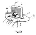
- FIG. 8is the insertion head of the second example embodiment, with the insertion means situated in the insertion position;
- FIG. 9is a handle of the insertion head of the second example embodiment.
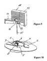
- FIG. 10is a base of the insertion head of the second example embodiment, with the insertion means situated in the insertion position;
- FIG. 11is a system consisting of an insertion head and an inserter of a first example embodiment, before it has been activated;
- FIG. 12is the system of the first example embodiment, after it has been activated
- FIG. 13is a system consisting of an insertion head and an inserter of a second example embodiment, before the insertion head has been activated;
- FIG. 14is the system of the second example embodiment, after it has been activated.
- FIG. 15is the system of the second example embodiment, after the insertion head has been positioned on the surface of a tissue.
- FIG. 1shows an insertion head of a first example embodiment, in a longitudinal section.
- the insertion headcomprises a base comprising an accommodating part or receptacle 1 and a flat part 2 , which are moulded from plastic in one piece.
- the lower side U of the base 1 , 2can be positioned on organic tissue.
- the insertion headalso comprises a two-part handle comprising a first handle component 10 and a second handle component 12 .
- the handle component 10is immovably but detachably coupled to the base.
- the handle component 12is movably held on the handle component 10 and the handle component 12 may be linearly shifted both relative to the handle component 10 and relative to the base 1 , 2 .
- the axis of mobility of the handle component 12points parallel to a lower side U of the base 1 , 2 .
- the direction of mobilityis indicated on the upper side of the handle component 12 by an arrow.
- the base 1 , 2mounts an insertion means 5 such that it can pivot about a rotational axis parallel to the lower side U.
- the insertion means 5is elongated, and in the example embodiment, it is configured as a flexible cannula.
- An injection means 15which protrudes through the insertion means 5 , is configured as a thin needle having a sufficient bending resistance to inject the injection means 15 , together with the surrounding, conforming or nestling insertion means 5 , through the surface of the skin into subcutaneous tissue and so insert the insertion means 5 .
- an adhesive padis attached to the lower side U for fixing the insertion head on the tissue or surface of the skin.
- a joint element 6which forms a shaft of a rotary joint with the rotational axis as the joint axis may provide a pivot for the insertion means 5 and the injection means 15 .
- the base 1 , 2may form another joint element of the rotary joint in the form of a socket or as applicable also an open bearing eye.
- an externally toothed wheel 8is arranged on each of the two sides of the joint element 6 and is non-rotationally coupled to the joint element 6 , for example is moulded in one piece.
- One of the two toothed wheels 8can be seen in FIG. 1 .
- the otheris positioned on the opposite side of the joint element 6 and is hidden by the accommodating part 1 of the base 1 , 2 .
- the injection means 15protrudes through the joint element 6 .
- a supply 7 for a medicinal fluid, for example insulin,is coupled to the joint element 6 .
- the supply 7projects from the joint element 6 , roughly at right angles to the insertion means 5 .
- the joint element 6together with the supply 7 , the toothed wheels 8 , the insertion means 5 and the injection means 15 , forms a unit in relation to the rotational movement of the joint element 6 and the toothed wheels 8 and the pivoting movement of the other components mentioned.
- the movable handle component 12is provided with two toothed rods 18 which are each in toothed engagement with one of the toothed wheels 8 . Of the two toothed rods 18 , only the one co-operating with the hidden toothed wheel is depicted in FIG. 1 . An identical toothed rod 18 co-operates with the toothed wheel 8 depicted in FIG. 1 .
- the handle component 12If the handle component 12 is shifted in the direction indicated by the directional arrow, during which movement the first handle component 10 guides the handle component 12 , the two toothed rods 18 mate with the two toothed wheels 8 , such that the shifting movement of the handle component 12 is transmitted into a rotational movement of the joint element 6 and a pivoting movement of the insertion means 5 , the injection means 15 and the supply 7 .
- the pivoting movementtransfers the insertion means 5 from its protective position, shown in FIG. 1 , into an insertion position.
- the insertion means 5 and the injection means 15point parallel or substantially parallel to the lower side U of the base 1 , 2 .
- the insertion means 5 and the portion of the injection means 15 protruding in the same direction beyond the joint element 6may be accommodated in their common protective position in a hollow space enclosed by the accommodating part or receptacle 1 , except for the lower side U. Having the insertion means 5 situated in the protective position may reduce the chance of injury on the injection means 15 .
- the insertion means 5 and the injection means 15 in the protected positionmay prevent damage due to careless handling.
- the receptacle 1may form a blind, such that the user cannot see the injection means 15 from the upper side of the insertion head, nor from a lateral angle of view.
- An adhesive padwhich may be attached to the lower side, may be provided with a passage slit for the insertion means 5 and the injection means 15 .
- the toothed rods 18are respectively arranged on a lower side, facing the lower side U, of two bend-resistant tongues which protrude in the movement direction from a lateral part of the handle component 12 .
- at least one other tongueprotrudes in the movement direction from the lateral part of the handle component 12 and serves to linearly guide the movable handle component 12 on a guide provided by the handle component 10 .
- the usergrips the handle of the insertion head between his thumb and forefinger.
- the handle components 10 and 12are each provided with a correspondingly shaped lateral indentation.
- the movable handle component 12is pressed up to and against a stopper provided by the first handle component 10 .
- the two toothed rods 18mate with the toothed wheels 8 , such that the translational movement of the handle component 12 is transmitted into a rotational movement of the joint element 6 and thus into a pivoting movement of the insertion means 5 and the injection means 15 .
- the path of the handle component 12 , the diameter of the toothed wheels 8 and the fineness of the toothingsmay be chosen such that a movement of the handle component 12 by a few millimetres, for example 4 or 5 mm, generates a pivoting movement of the insertion means 5 and the injection means 15 by a pivoting angle of at or around 90° into an insertion position in which the insertion means 5 and the injection means 15 protrude, at least roughly at right angles, beyond the lower side U of the base 1 , 2 .
- FIG. 2shows the insertion head with the insertion and injection means 5 , 15 situated in the insertion position.
- the injection means 15has been coupled to the handle 10 , 12 , e.g., to the movable handle component 12 .
- the protective positionFIG. 1
- a connecting element 16is arranged on, e.g., fastened to, an end of the injection means 15 , which is proximal in the insertion position and by which the injection means 15 protrudes beyond the joint element 6 .
- the connecting element 16comprises one or two protruding fins with which it grips behind a connecting counter element of the handle component 12 in relation to the longitudinal direction of the injection means 15 .
- the connecting counter element of the movable handle component 12may be configured as a collar area which may grip the connecting element 16 .
- the userIn order to position the insertion head on the surface of a tissue and insert the insertion means 5 into the tissue, the user holds the insertion head by its handle 10 , 12 and moves it towards the surface of the tissue until the injection means 15 penetrates through the surface of the tissue, e.g., human skin, and penetrates into the skin.
- the conforming or nestling insertion means 5penetrates along with the injection means 15 , until the lower side U of the insertion head is placed on the surface of the tissue and adhesively fixed on the surface of the skin, for example by means of an adhesive pad.
- the injection means 15In order to administer the medicine, the injection means 15 is removed and the supply 7 is coupled to a medicine reservoir, such as a medicine pump, via a connector which co-operates with the supply 7 .
- a medicine reservoirsuch as a medicine pump
- handle 10 , 12is detached from the base 1 , 2 before the supply 7 is coupled to the base.
- the handle components 10 , 12may be detached from the base 1 , 2 .
- the couplingmay be automatically released when the handle component 12 is moved, such that the handle 10 , 12 can be drawn off in the proximal direction, e.g., upwards in FIG. 2 .
- the injection means 15slides through the insertion means 5 and the joint element 6 resulting in the flow cross-section of the insertion means 5 being exposed such that once the injection means 15 has been drawn out, the flow cross-section is also simultaneously fluidly coupled to the supply 7 .
- the insertion headcan be embodied as described for example in DE 198 21 723 C1 and DE 10 2004 039 408.3, which are herein incorporated by reference in their entireties, for any purpose.
- FIGS. 3 and 4show the two parts of the insertion head detached from each other, i.e. the base 1 , 2 comprising the insertion means 5 on the one hand, and the handle 10 , 12 comprising the injection means 15 on the other hand, in a mutually aligned position in which the longitudinal axis of the insertion means 5 and the longitudinal axis of the injection means 15 are flush with each other.
- a cavity 3 in the base 1 , 2is depicted in which the parts are coupled and the handle component 12 is moved, and one of the two toothed rods 18 retracts into the cavity 3 and mates with the toothed wheel 8 arranged in the cavity 3 .
- the cavity 3is slit-shaped.
- a connecting element 19 of the handle 10 , 12is depicted, which when coupled, engages in a positive fit with a connecting counter element of the base 1 , 2 and holds the handle 10 , 12 on the base 1 , 2 and, in combination with contact areas of the handle 10 , 12 and the base 1 , 2 , fixes it relative to the base 1 , 2 .
- the connecting element 19protrudes like a stub from an elastic flap 13 projecting from the handle component 10 in the distal region, in a direction pointing parallel to the lower side U of the base 1 , 2 and, when coupled, into a receptacle of the base 1 , 2 , for example a hole shaped congruently with the connecting element 19 , such that a movement of the handle 10 , 12 in the longitudinal direction of the injection portion 15 is prevented when the connection exists.
- FIGS. 5 and 6again show the parts of the insertion head detached from each other, in a view onto the rear side facing away in FIGS. 1 to 4 .
- the connecting counter element 9 of the base 1 , 2 depicted in FIG. 6which when coupled, i.e. in engagement with the connecting element 19 , holds the handle 10 , 12 on the base 1 , 2 .
- the base 1 , 2 shown individually in FIGS. 4 and 6which is the support for the insertion means 5 and for the parts 6 , 7 and 8 which together with it form a pivoting unit, remains on the surface of the tissue and is in this sense a retained part.
- the handle 10 , 12which then serves as a support for the injection means 15 , is disposed of or as applicable detached from the injection means 15 again and supplied to another application, while the injection means 15 is disposed of.
- the retained part 1 - 9may be flat and worn under the clothes.
- the insertion means 5may be flexible yet stable such that the insertion means is comfortably insertable but stable so that medicine may be reliably supplied.
- the handle 10 , 12may also be used in embodiments of the insertion head in which the insertion means is not inherently flexible like the insertion means 5 , but is rather bend-resistant enough for injecting without being externally stabilized.
- the additional injection means 15may be omitted.
- the handle 10 , 12hands the insertion head and does not support a stabilising injection means 15 .
- An insertion means 5 modified in this waymay be configured as an injection cannula having a hollow cross-section or as an injection needle having a solid cross-section and one or more flow channels at its outer circumference, which becomes more flexible after it has been inserted, due to interaction with the tissue.
- FIGS. 7 to 10show a second example embodiment of an insertion head. Aside from the differences described below, the insertion head of the second example embodiment corresponds to the insertion head of the first example embodiment.
- an adhesive pad which is fastened to the lower side Uis shown, such as could also be attached to the insertion head of the first example embodiment.
- the receptacle 1 and the first handle component 11have been modified as compared to the first example embodiment. Unlike the first example embodiment, the insertion means 5 and the injection means 15 are accommodated in the receptacle 1 , which is provided by the accommodating part, over a short portion.
- the handle component 11forms a receptacle 14 for the insertion means 5 and the injection means 15 .
- the receptacle 1is laterally provided with a cavity 4 , in the form of a slit, which is open towards the lower side U and through which the insertion means 5 and the injection means 15 protrude out of the receptacle 1 in the protective position.
- the receptacle 1is in turn accommodated in the receptacle 14 .
- the receptacle 14is open towards the lower side U, but otherwise encloses the insertion means 5 and the injection means 15 , for example using an opaque material.
- the userIn order to pivot the insertion means 5 and the injection means 15 from the protective position into the insertion position, the user performs the hand movements described in relation to the first example embodiment, i.e. the movable handle component 12 is pressed against the modified handle component 11 .
- the insertion means 5 and the injection means 15 in the cavity 4pivot out of the receptacle 1 and receptacle 14 , into the insertion position.
- FIG. 8shows the insertion head of the second example embodiment, with the insertion means 5 and the injection means 15 situated in the insertion position.
- FIGS. 9 and 10correspond to FIGS. 3 and 4 of the first example embodiment.
- the base 1 , 2may be shortened as compared to the base 1 , 2 of the first example embodiment, because base 1 , 2 does not protect the insertion and injection means 5 , 15 , but rather the handle 11 , 12 serves a protecting function for the insertion means 5 and the injection means 15 in their protective position.
- FIG. 11shows a system of a first example embodiment, consisting of the insertion head of the first example embodiment and an inserter, which serves to position the insertion head on the tissue, such that the user does not have to grip the insertion head between his fingers when positioning it. For example, the user does not hold the insertion head by its handle when the insertion means 5 is transferred into the insertion position. This activation of the insertion head is performed with the aid of the inserter. The user may therefore be securely protected against pricking injuries, and the insertion means 5 and the injection means 15 may be securely protected against damage due to careless handling, i.e. by the inserter.
- the insertercomprises an inserter casing 20 configured as a sleeve part comprising a base and may exhibit the shape of a cup when viewed from the outside.
- the inserter casing 20accommodates a holding means and a drive for the insertion head.
- the holding meanscomprises a holding spring, for example a leaf spring, which holds the insertion head in the initial position shown in FIG. 11 relative to the inserter casing 20 .
- the holding springgrips behind a holding structure 17 , which is arranged on the handle 10 , 12 depicted in FIGS. 1 , 2 , 3 and 5 .
- the holding engagementmay be released, against the restoring elasticity force of the holding spring.
- the drivecomprises an advancing element 22 , which may be arranged in the inserter casing 20 such that it is linearly movable in and counter to an advancing direction V.
- the advancing direction Vcoincides with a central longitudinal axis of the inserter casing 20 .
- the drivealso comprises a force generator 23 which acts on the advancing element 22 in the advancing direction V.
- the force generator 23comprises two pairs of legs 24 which may be coupled via a joint, and the two pairs of legs 24 may be arranged symmetrically with respect to the central longitudinal axis of the inserter casing 20 , i.e. symmetrically with respect to the advancing direction V.
- Each of the pairs of legsis suspended in a rotary joint 25 which is fixed relative to the inserter casing 20 .
- the two legs 24 of each pair of legsmay be rotatably coupled in a free rotary joint 26 .
- the leg 24 facing away from the fixed joint 25may also be coupled to the advancing element 22 in a rotary joint 27 .
- One or more springs(not shown) may tense the leg-joint-advancing element arrangement in the advancing direction V.
- the arrangement of legs 24 and joints 25 , 26 and 27guides the advancing element 22 .
- the inner surface area of the inserter casing 20may guide the advancing element 22 .
- a blocking member 29may also be provided which is in blocking engagement with the inserter casing 20 . The blocking engagement may prevent an advancing movement of the advancing element 22 .
- the blocking member 29may form the blocking engagement with the cladding structure provided by the inserter casing 20 , or equally with another structure which is fixedly coupled to it in relation to the advancing direction V.
- the blocking engagementmay be released by operating a push-button trigger 28 .
- the inserteralso includes an activating member 21 coupled to the inserter casing 20 such that it can move in and counter to the advancing direction V.
- the activating member 21forms a bushing in relation to the inserter casing 20 , such that a two-part telescoping inserter casing comprising casing parts 20 and 21 is obtained.
- the casing part 21shall continue to be referred to as the activating member.
- the activating member 21forms the lower side U 21 of the inserter, via which the inserter may be placed on the surface of the tissue in order to position the insertion head. In the initial position of the insertion head in FIG. 11 , the lower side U 21 of the inserter and the lower side U of the held insertion head each point in the advancing direction V, which may form a surface, e.g., substantially normal surface, for the two lower sides.
- the activating member 21comprises an outer sleeve part and an inner sleeve part which may be coupled on the lower side U 21 and leave an annular gap.
- the inserter casing 20protrudes into the annular gap and guides the activating member 21 in a sliding movement.
- the activating member 21assumes a retracted position relative to the inserter casing 20 , and the inserter exhibits its shortest length as measured in the advancing direction V.
- the insertion headis inserted, i.e. brought into holding engagement with the holding means of the inserter.
- the insertermay also be placed over the insertion head lying on a support.
- the position and geometry of the holding meansmay be chosen such that the holding engagement is automatically established when the inserter is placed on the insertion head.
- the insertion means 5 of the insertion headis situated in its protective position. In this sense, the insertion head may be inactive.
- the inserterincludes means, i.e. the activating member 21 , which when operated can move the insertion means into the insertion position and so activate the insertion head.
- the activating member 21 and the insertion headtogether form a joint, e.g., a cam joint.
- the two joint elements of the jointare a guiding cam 21 a , which forms the activating member 21 , and an engaging element 12 a provided by the movable handle component 12 .
- the movable handle component 12may form an input and/or receiving member of the insertion head. If the activating member 21 is moved in the advancing direction V relative to the inserter casing 20 , the guiding cam 21 a slides over the engaging element 12 a , i.e.
- the handle component 12is moved transverse to the advancing direction V, towards the additional handle component 10 , and the insertion means 5 pivots into the insertion position, as described for the insertion head itself.
- the movable handle component 12forms the engaging element 12 a at its upper end facing away from the base 1 , 2 , e.g., with its outer edge.
- the guiding cam 21 afaces the lower side U 21 of the inserter.
- the inclinationis chosen such that the guiding cam 21 a is inclined, from an end facing away from the lower side U 21 , in the advancing direction V away from the insertion head and/or the insertion means 5 which is pivoted out when activated or from the central longitudinal axis of the inserter.
- the angle of inclinationmay be constant throughout such that the guiding cam 21 a is a slant, i.e. an oblique line or area.
- the usermay be suitable for the user to hold the inserter by the activating member 21 with one hand after the insertion head has been accommodated, for example by gripping around the activating member 21 , and to draw the inserter casing 20 counter to the advancing direction V relative to the held activating member 21 with the other hand.
- Thisis also understood to mean operating the activating member.
- the advancing element 22 and the force generator 23may be moved together with the inserter casing 20 relative to the activating member 21 .
- the insertion head held in the initial positionmay be slaved by the holding means, i.e. it may be moved relative to the activating member 21 , counter to the advancing direction V.
- the engaging element 12 aslides along the guiding cam 21 a .
- the movable handle component 12is moved transverse to the advancing direction V, and the insertion means 5 pivots into the insertion position.
- the insertion headmay be activated at the end of the extending movement which the inserter casing 20 and the activating member 21 perform relative to each other.
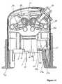
- FIG. 12shows the system consisting of the inserter and the insertion head in its activated state.
- the inserter casing 20 and the activating member 21assume their extended position relative to each other.
- the walls of the inserter casing 20 and the activating member 21surround the activated insertion head up to and beyond the free end of the insertion means 5 and the injection means 15 , i.e. the tip of the injection means 15 is slightly short of the lower side U 21 of the inserter.
- the inserter casing 20 and the activating member 21are blocked relative to each other. Relative movements in or counter to the advancing direction V are not possible in the blocked state. Upon reaching the extended position, the inserter casing 20 and the activating member 21 may be automatically blocked on each other.
- a usermay place the inserter on the surface of the skin.
- the userpresses the trigger 28 .
- the trigger 28acts on the blocking member 29 via a cam joint, for example, via a pair of slants. Due to the action of the trigger 28 , the blocking member 29 may be moved out of its blocking engagement with the inserter casing 20 , such that the advancing element 22 can be moved in the advancing direction V due to the action of the force generator 23 .
- the force generator 23may abruptly accelerate the advancing element 22 , and the advancing element 22 may act on the insertion head like a hammer.
- the holding spring springs out of its holding engagement with the holding structure 17 of the insertion headi.e. the holding engagement is released.
- the acceleration of the advancing element 22 in the advancing direction Vmay be large enough for the pressing contact between the advancing element 22 and the insertion head to be securely maintained, at least until the lower side U of the insertion head is at the same height as the lower side U 21 of the inserter and is thus positioned on the surface of the tissue.
- the injection means 15 and insertion means 5may have penetrated through the surface of the skin and into the tissue.
- the usergrips the handle 10 , 12 and draws it off from the base 1 , 2 , where the injection means 15 may be automatically drawn out of the insertion means 5 and off from the base 1 , 2 .
- the holding engagement between the holding means of the inserter and the holding structure 17 of the insertion headmay be maintained by a modification to the inserter and may not be released by the acceleration of the advancing element 22 , as in the example embodiment described.
- the holding meansmay be coupled fixedly to the advancing element 22 , such that it is slaved in its discharge movement in the advancing direction V.
- the insertermay be fitted with a deflector which, after the inserter has been removed from the tissue and when the inserter casing 20 and the activating member 21 are shifted together, automatically releases the insertion head from the holding engagement.
- a deflectormay also be provided independently of the activating member 21 , and may be separately operated in order to release the holding engagement.
- FIGS. 13-15show a system of a second example embodiment, consisting of an insertion head and an inserter.
- the insertion headmay be any of the insertion heads provided in the example embodiments, or combinations or variants thereof.
- the inserteris modified.
- the components of the inserter of the second example embodiment which in relation to their functionare comparable to the components of the inserter of the first example embodiment are respectively marked with the reference signs of the first example embodiment, raised by the number 10 .
- the statements made with respect to the first example embodimentmay apply to the inserter casing 30 and the activating member 31 , as far as their shape and connection and also their relative mobility are concerned.
- the inserter of the second example embodimentdiffers from the inserter of the first example embodiment with regard to the joint via which the activating member 31 acts on the insertion head, in order to activate it through the drawing-up movement of the inserter casing 30 relative to the activating member 31 .
- the inserteritself forms the joint, i.e. comprising two joint elements 31 a and 41 a , one of which forms the activating member 31 and the other of which forms an effector member 41 .
- the effector member 41may be mounted by the inserter casing 30 such that it may be moved back and forth transverse to the advancing direction V, e.g., at right angles to the advancing direction V.
- the joint 31 a , 41 amay be a cam joint.
- the guiding cam 31 amay correspond to the guiding cam 21 a of the first example embodiment.
- the effector member 41forms the engaging element 41 a which slides along the guiding cam 31 a when the inserter is lengthened and, due to the inclined profile of the guiding cam 31 a , generates a transverse movement of the effector member 41 towards the central longitudinal axis of the inserter when the inserter is drawn up.
- the movement pointing counter to the advancing direction V, which the inserter casing 30 performs relative to the activating member 31 when it is drawn up,is thus converted in the joint 31 a , 41 a into the transverse movement of the effector member 41 .
- joint element or engaging element 41 amay be configured like a guiding cam, but in terms of transmission may be referred to here as the engaging element.
- the engaging element 41 amay alternatively, for example, also be shaped as a cam or burl.
- the engaging element 41 amay equally be referred to as a guiding cam, and in another modification, the joint element 31 a may be configured as a protruding cam or burl.
- the interface via which the inserter activates the insertion headmay be configured as a pressing contact and exists between the effector member 41 and the receiving member or movable handle component 12 of the insertion head.
- This pressing contacte.g., loosely pressing contact, may simplify handling because a joint connection may not need to be established in order to the activate the insertion head. For example, it may be sufficient to accommodate the insertion head in combination with operating the activating member 31 , which, in the example embodiments may be performed by the drawing-up movement.
- the pressing contacti.e. the pressing force exerted by the effector member 41 , acts on the movable handle component 12 parallel to the direction of its mobility relative to the base 1 , 2 .
- FIG. 14shows the system with the insertion head activated.
- the insertion means 5 and the injection means 15have been pivoted into the insertion position, such that their common longitudinal axis points in the advancing direction V.
- the movable handle component 12has released the connection between the handle 10 , 12 and the base 1 , 2 , as described for the insertion head.
- the frictional fit between the insertion means 5 and the injection means 15holds the base 1 , 2 on the handle 10 , 12 in the holding engagement, as in the first example embodiment.
- the blocking engagementin which the blocking member 39 is still situated with the inserter casing 30 or a structure fixedly coupled to the inserter casing 30 , may be released by operating the trigger 38 , and the force generator 33 accelerates the advancing element 32 in the advancing direction V.
- the accelerationmay be abrupt, such that the drive means 32 , 33 of the second example embodiment also acts like a hammer.
- the drive forcemay be generated by two leg springs, each one of which acts on one of the two pairs of legs.
- the legs 24which are fastened via the rotary joints 35 (fixed), 36 and 37 and are coupled via a toothed engagement which may provide a synchronous extending movement of the two pairs of legs.
- the effector member 41id moved from the position shown in FIG. 14 back again into the position shown in FIG. 13 .
- the activating member 31 and the effector member 41form an additional joint 31 b , 41 b , which in the example embodiment is a cam joint.
- the activating member 31forms the guiding cam 31 b for the additional joint, and the effector member 41 forms the engaging element 41 b .
- the guiding cam 31 bmay run parallel or substantially parallel to the guiding cam 31 a .
- the guiding cams 31 a and 31 bmay be provided on the inner sleeve part of the activating member 31 such that the guiding cam 31 a is arranged at the inner area and the guiding cam 31 b is arranged at the outer area of the inner sleeve part.
- the guiding cams 31 a , 31 bmay oppose each other at roughly the same height in terms of the advancing direction V.
- the engaging element 41 bmay also oppose the engaging element 41 a at a distance, such that the inner sleeve part of the activating member 31 may retract and extend between the two engaging elements 41 a and 41 b.
- FIG. 15shows the system of the second example embodiment with the insertion head positioned.
- the inserteris removed from the insertion head.
- the usermay then draw the handle 10 , 12 off from the base 1 , 2 and couples the insertion head to a catheter of an infusion pump.
- the holding meansmay be coupled fixedly to the advancing element 32 and may hold the handle 10 , 12 , and the inserter with the handle 10 , 12 may be removed from the base.
- the holding engagementmay be released, for example by means of an additional deflector, and the handle 10 , 12 may disposed of, with the injection means 10 or on its own.
- the usershifts the inserter casing 30 and the activating member 31 back together into the retracted position, as shown in FIG. 13 with the insertion head retracted.
- the inner sleeve part of the activating member 31moves between the engaging elements 41 a and 41 b of the effector member 41 .
- the additional joint connection between the guiding cam 31 b and the engaging element 41 bmay be established.
- the effector member 41may thus be moved in the joint 31 b , 41 b , into the end position assumed in FIG. 13 , i.e. is moved transversely, e.g., radially, outwards in relation to the central longitudinal axis of the inserter.
- the advancing element 32which is extended due to the action of the spring means 33 in the advancing direction V, opposes an end-facing side of the inner sleeve part facing away from the lower side U 31 of the activating member 31 .
- the advancing movement of the advancing element 32may be stopped by an abutting contact against this end-facing side.
- the activating member 31is geometrically dimensioned such that when the telescope 30 , 31 is in the extended position, the activating member 31 stops the advancing element 32 exactly when the lower side U of the insertion head has reached the height of the lower side U 31 and therefore just contacts the surface of the skin when the inserter is placed on the skin.
- the advancing element 32may be pressed deeper into the inserter casing 30 , against the force of the force generator 33 , due to the abutting contact by the activating member 31 , until the blocking member 39 is in blocking engagement again, as shown by way of example in FIGS. 13 and 14 .
Landscapes
- Health & Medical Sciences (AREA)
- Life Sciences & Earth Sciences (AREA)
- Public Health (AREA)
- Veterinary Medicine (AREA)
- Biomedical Technology (AREA)
- Heart & Thoracic Surgery (AREA)
- Hematology (AREA)
- Engineering & Computer Science (AREA)
- Animal Behavior & Ethology (AREA)
- General Health & Medical Sciences (AREA)
- Anesthesiology (AREA)
- Vascular Medicine (AREA)
- Biophysics (AREA)
- Pulmonology (AREA)
- Infusion, Injection, And Reservoir Apparatuses (AREA)
- Paper (AREA)
- Finger-Pressure Massage (AREA)
- Surgical Instruments (AREA)
- Automatic Assembly (AREA)
- Prostheses (AREA)
Abstract
Description
Claims (35)
Applications Claiming Priority (6)
| Application Number | Priority Date | Filing Date | Title |
|---|---|---|---|
| EP05020156AEP1764126B1 (en) | 2005-09-15 | 2005-09-15 | Injection head with handle |
| EP05020155AEP1764125B1 (en) | 2005-09-15 | 2005-09-15 | System comprising an insertion head and an inserter |
| EP05020157AEP1764122B1 (en) | 2005-09-15 | 2005-09-15 | Injection head with needle protection in the handle |
| EP05020155.7 | 2005-09-15 | ||
| EP05020155 | 2005-09-15 | ||
| PCT/EP2006/008763WO2007031237A1 (en) | 2005-09-15 | 2006-09-08 | System composed of an insertion head and an inserter |
Related Parent Applications (1)
| Application Number | Title | Priority Date | Filing Date |
|---|---|---|---|
| PCT/EP2006/008763ContinuationWO2007031237A1 (en) | 2005-09-15 | 2006-09-08 | System composed of an insertion head and an inserter |
Publications (2)
| Publication Number | Publication Date |
|---|---|
| US20080275407A1 US20080275407A1 (en) | 2008-11-06 |
| US8262618B2true US8262618B2 (en) | 2012-09-11 |
Family
ID=38947715
Family Applications (1)
| Application Number | Title | Priority Date | Filing Date |
|---|---|---|---|
| US12/048,591Expired - Fee RelatedUS8262618B2 (en) | 2005-09-15 | 2008-03-14 | System consisting of an insertion head and an inserter |
Country Status (9)
| Country | Link |
|---|---|
| US (1) | US8262618B2 (en) |
| EP (3) | EP1764126B1 (en) |
| JP (1) | JP4776686B2 (en) |
| CN (1) | CN101309718B (en) |
| AT (3) | ATE524212T1 (en) |
| CA (1) | CA2621639C (en) |
| DE (1) | DE502005011091D1 (en) |
| DK (2) | DK1764125T5 (en) |
| WO (3) | WO2007031126A1 (en) |
Cited By (41)
| Publication number | Priority date | Publication date | Assignee | Title |
|---|---|---|---|---|
| US20110213340A1 (en)* | 2008-05-14 | 2011-09-01 | Howell Glade H | Separatable infusion set with cleanable interface and straight line attachment |
| USD684685S1 (en) | 2012-04-13 | 2013-06-18 | Becton, Dickinson And Company | Infusion device button |
| USD684686S1 (en) | 2012-04-13 | 2013-06-18 | Becton, Dickinson And Company | Infusion device button |
| USD685084S1 (en) | 2012-04-13 | 2013-06-25 | Becton, Dickinson And Company | Infusion device |
| USD685083S1 (en) | 2012-04-13 | 2013-06-25 | Becton, Dickinson And Company | Infusion device |
| USD687141S1 (en) | 2012-04-13 | 2013-07-30 | Becton, Dickinson And Company | Infusion device |
| USD687140S1 (en) | 2012-04-13 | 2013-07-30 | Becton, Dickinson And Company | Infusion device |
| USD687536S1 (en) | 2012-04-13 | 2013-08-06 | Becton, Dickinson And Company | Infusion device |
| USD688784S1 (en) | 2012-04-13 | 2013-08-27 | Becton, Dickinson And Company | Infusion device |
| US20130253431A1 (en)* | 2009-11-26 | 2013-09-26 | Roche Diagnostics International Ag | Externally triggerable cannula assembly |
| US8784383B2 (en) | 2010-11-30 | 2014-07-22 | Becton, Dickinson And Company | Insulin pump dermal infusion set having partially integrated mechanized cannula insertion with disposable activation portion |
| US8795234B2 (en) | 2010-11-30 | 2014-08-05 | Becton, Dickinson And Company | Integrated spring-activated ballistic insertion for drug infusion device |
| US8795230B2 (en) | 2010-11-30 | 2014-08-05 | Becton, Dickinson And Company | Adjustable height needle infusion device |
| US8814831B2 (en) | 2010-11-30 | 2014-08-26 | Becton, Dickinson And Company | Ballistic microneedle infusion device |
| EP2549918B1 (en) | 2010-03-24 | 2016-06-29 | Abbott Diabetes Care, Inc. | Medical device inserters and processes of inserting and using medical devices |
| US9782536B2 (en) | 2009-01-12 | 2017-10-10 | Becton, Dickinson And Company | Infusion set and/or patch pump having at least one of an in-dwelling rigid catheter with flexible features and/or a flexible catheter attachment |
| US9931066B2 (en) | 2011-12-11 | 2018-04-03 | Abbott Diabetes Care Inc. | Analyte sensor devices, connections, and methods |
| US9950109B2 (en) | 2010-11-30 | 2018-04-24 | Becton, Dickinson And Company | Slide-activated angled inserter and cantilevered ballistic insertion for intradermal drug infusion |
| US9993188B2 (en) | 2009-02-03 | 2018-06-12 | Abbott Diabetes Care Inc. | Analyte sensor and apparatus for insertion of the sensor |
| US10213139B2 (en) | 2015-05-14 | 2019-02-26 | Abbott Diabetes Care Inc. | Systems, devices, and methods for assembling an applicator and sensor control device |
| US10674944B2 (en) | 2015-05-14 | 2020-06-09 | Abbott Diabetes Care Inc. | Compact medical device inserters and related systems and methods |
| US10863944B2 (en) | 2017-06-23 | 2020-12-15 | Dexcom, Inc. | Transcutaneous analyte sensors, applicators therefor, and associated methods |
| US10898115B2 (en) | 2015-12-30 | 2021-01-26 | Dexcom, Inc. | Transcutaneous analyte sensor systems and methods |
| USD924406S1 (en) | 2010-02-01 | 2021-07-06 | Abbott Diabetes Care Inc. | Analyte sensor inserter |
| US11071478B2 (en) | 2017-01-23 | 2021-07-27 | Abbott Diabetes Care Inc. | Systems, devices and methods for analyte sensor insertion |
| USD926325S1 (en) | 2018-06-22 | 2021-07-27 | Dexcom, Inc. | Wearable medical monitoring device |
| US11331022B2 (en) | 2017-10-24 | 2022-05-17 | Dexcom, Inc. | Pre-connected analyte sensors |
| US11350862B2 (en) | 2017-10-24 | 2022-06-07 | Dexcom, Inc. | Pre-connected analyte sensors |
| US20220194644A1 (en)* | 2014-02-11 | 2022-06-23 | Dexcom, Inc. | Method of packaging analyte sensors |
| USD961778S1 (en) | 2006-02-28 | 2022-08-23 | Abbott Diabetes Care Inc. | Analyte sensor device |
| USD962446S1 (en) | 2009-08-31 | 2022-08-30 | Abbott Diabetes Care, Inc. | Analyte sensor device |
| US11446434B2 (en) | 2019-02-22 | 2022-09-20 | Deka Products Limited Partnership | Infusion set and inserter assembly systems and methods |
| USD979766S1 (en) | 2005-09-30 | 2023-02-28 | Abbott Diabetes Care Inc. | Analyte sensor device |
| USD982762S1 (en) | 2020-12-21 | 2023-04-04 | Abbott Diabetes Care Inc. | Analyte sensor inserter |
| USD1002852S1 (en) | 2019-06-06 | 2023-10-24 | Abbott Diabetes Care Inc. | Analyte sensor device |
| USD1043976S1 (en) | 2022-08-26 | 2024-09-24 | Deka Products Limited Partnership | Fluid transfer connector |
| USD1057941S1 (en) | 2022-08-26 | 2025-01-14 | Deka Products Limited Partnership | Patient care assembly component |
| US12239463B2 (en) | 2020-08-31 | 2025-03-04 | Abbott Diabetes Care Inc. | Systems, devices, and methods for analyte sensor insertion |
| US12274548B2 (en) | 2006-10-23 | 2025-04-15 | Abbott Diabetes Care Inc. | Sensor insertion devices and methods of use |
| USD1090862S1 (en) | 2022-08-26 | 2025-08-26 | Deka Products Limited Partnership | Adhering assembly for medical devices and the like |
| US12408847B2 (en) | 2018-06-07 | 2025-09-09 | Abbott Diabetes Care Inc. | Focused sterilization and sterilized sub-assemblies for analyte monitoring systems |
Families Citing this family (70)
| Publication number | Priority date | Publication date | Assignee | Title |
|---|---|---|---|---|
| US20190357827A1 (en) | 2003-08-01 | 2019-11-28 | Dexcom, Inc. | Analyte sensor |
| WO2009048462A1 (en) | 2007-10-09 | 2009-04-16 | Dexcom, Inc. | Integrated insulin delivery system with continuous glucose sensor |
| MXPA06010784A (en) | 2004-03-26 | 2006-12-15 | Unomedical As | Injector device for infusion set. |
| US8062250B2 (en) | 2004-08-10 | 2011-11-22 | Unomedical A/S | Cannula device |
| EP1762259B2 (en) | 2005-09-12 | 2025-01-01 | Unomedical A/S | Inserter for an infusion set with a first and second spring units |
| DK1962926T3 (en) | 2005-12-23 | 2009-09-28 | Unomedical As | injection device |
| WO2007098771A2 (en) | 2006-02-28 | 2007-09-07 | Unomedical A/S | Inserter for infusion part and infusion part provided with needle protector |
| CA2653631A1 (en) | 2006-06-07 | 2007-12-13 | Unomedical A/S | Inserter |
| CA2653764A1 (en) | 2006-06-09 | 2007-12-13 | Unomedical A/S | Mounting pad |
| JP2009545341A (en) | 2006-08-02 | 2009-12-24 | ウノメディカル アクティーゼルスカブ | Cannula and delivery device |
| JP2010501211A (en)* | 2006-08-24 | 2010-01-21 | エフ.ホフマン−ラ ロシュ アーゲー | Puncture device for puncturing a puncture head such as an infusion set |
| EP1917990A1 (en) | 2006-10-31 | 2008-05-07 | Unomedical A/S | Infusion set |
| DK1970083T3 (en) | 2007-03-14 | 2017-09-11 | Hoffmann La Roche | Insertion device for an insertion head, especially for an infusion set |
| ATE485858T1 (en)* | 2007-03-14 | 2010-11-15 | Hoffmann La Roche | INSERTION HEAD FOR MEDICAL OR PHARMACEUTICAL APPLICATIONS |
| ATE477011T1 (en) | 2007-03-14 | 2010-08-15 | Hoffmann La Roche | INSERTION DEVICE FOR AN INSERTION HEAD, IN PARTICULAR FOR AN INFUSION SET |
| EP2155311B1 (en) | 2007-06-20 | 2013-01-02 | Unomedical A/S | A method and an apparatus for making a catheter |
| AU2008270327A1 (en) | 2007-07-03 | 2009-01-08 | Unomedical A/S | Inserter having bistable equilibrium states |
| DE602008005153D1 (en) | 2007-07-10 | 2011-04-07 | Unomedical As | INSERT WITH TWO SPRINGS |
| EP2200677A1 (en)* | 2007-09-17 | 2010-06-30 | ICU Medical, Inc. | Insertion devices for infusion devices |
| ATE522240T1 (en) | 2008-02-13 | 2011-09-15 | Unomedical As | SEAL BETWEEN A CANNULAR PART AND A FLUID PATH |
| US9566384B2 (en) | 2008-02-20 | 2017-02-14 | Unomedical A/S | Insertion device with horizontally moving part |
| EP2174680B1 (en) | 2008-10-07 | 2011-10-05 | Roche Diagnostics GmbH | Insertion device |
| AU2009331635A1 (en) | 2008-12-22 | 2011-06-23 | Unomedical A/S | Medical device comprising adhesive pad |
| AU2010277755A1 (en) | 2009-07-30 | 2012-02-02 | Unomedical A/S | Inserter device with horizontal moving part |
| KR20120047896A (en) | 2009-08-07 | 2012-05-14 | 우노메디컬 에이/에스 | Delivery device with sensor and one or more cannulas |
| US10071198B2 (en) | 2012-11-02 | 2018-09-11 | West Pharma. Servicees IL, Ltd. | Adhesive structure for medical device |
| USD810279S1 (en) | 2009-09-15 | 2018-02-13 | Medimop Medical Projects Ltd. | Injector device |
| US8348898B2 (en)* | 2010-01-19 | 2013-01-08 | Medimop Medical Projects Ltd. | Automatic needle for drug pump |
| KR20130018783A (en) | 2010-03-30 | 2013-02-25 | 우노메디컬 에이/에스 | Medical device |
| EP2399623B1 (en)* | 2010-06-21 | 2016-02-17 | F.Hoffmann-La Roche Ag | Device for inserting an insertion member into the tissue of the body of a patient |
| DK2399624T3 (en)* | 2010-06-21 | 2016-01-18 | Hoffmann La Roche | A device for insertion of a soft part of the body tissue of a patient |
| WO2011160244A1 (en)* | 2010-06-21 | 2011-12-29 | F. Hoffmann-La Roche Ag | Device for inserting an insertion member into the tissue of the body of a patient |
| EP2433663A1 (en) | 2010-09-27 | 2012-03-28 | Unomedical A/S | Insertion system |
| EP2436412A1 (en) | 2010-10-04 | 2012-04-04 | Unomedical A/S | A sprinkler cannula |
| EP2697650B1 (en) | 2011-04-15 | 2020-09-30 | Dexcom, Inc. | Advanced analyte sensor calibration and error detection |
| WO2013050277A1 (en) | 2011-10-05 | 2013-04-11 | Unomedical A/S | Inserter for simultaneous insertion of multiple transcutaneous parts |
| EP2583715A1 (en) | 2011-10-19 | 2013-04-24 | Unomedical A/S | Infusion tube system and method for manufacture |
| US9440051B2 (en) | 2011-10-27 | 2016-09-13 | Unomedical A/S | Inserter for a multiplicity of subcutaneous parts |
| US9072827B2 (en) | 2012-03-26 | 2015-07-07 | Medimop Medical Projects Ltd. | Fail safe point protector for needle safety flap |
| IL221634A0 (en) | 2012-08-26 | 2012-12-31 | Medimop Medical Projects Ltd | Universal drug vial adapter |
| DE212014000169U1 (en) | 2013-08-07 | 2016-03-14 | Medimop Medical Projects Ltd. | Fluid transfer devices for use with infusion fluid containers |
| CN105658267B (en)* | 2013-09-05 | 2019-10-25 | 赛诺菲-安万特德国有限公司 | Driving mechanism for needle insertion assembly |
| CH709930A2 (en) | 2014-07-29 | 2016-01-29 | Tecpharma Licensing Ag | Insertion device for an infusion. |
| JP6358724B2 (en) | 2015-01-05 | 2018-07-18 | ウエスト・ファーマ.サービシーズ・イスラエル,リミテッド | Dual vial adapter assembly with easy removable pill adapter to ensure accurate use |
| PL3097933T3 (en) | 2015-05-26 | 2020-03-31 | F. Hoffmann-La Roche Ag | Cartridge and inserter for a medical system |
| CN113181477B (en) | 2015-06-04 | 2023-07-14 | 麦迪麦珀医疗工程有限公司 | Cartridge insertion for drug delivery device |
| WO2017009822A1 (en) | 2015-07-16 | 2017-01-19 | Medimop Medical Projects Ltd | Liquid drug transfer devices for secure telescopic snap fit on injection vials |
| CN115721558A (en) | 2015-11-25 | 2023-03-03 | 西部制药服务以色列有限公司 | Dual vial adapter assembly comprising a drug vial adapter having a self-sealing inlet valve |
| IL245800A0 (en) | 2016-05-24 | 2016-08-31 | West Pharma Services Il Ltd | Dual vial adapter assemblages including identical twin vial adapters |
| IL245803A0 (en) | 2016-05-24 | 2016-08-31 | West Pharma Services Il Ltd | Dual vial adapter assemblages including vented drug vial adapter and vented liquid vial adapter |
| CN109310831B (en) | 2016-06-02 | 2021-11-23 | 西医药服务以色列有限公司 | Three position needle retraction |
| IL246073A0 (en) | 2016-06-06 | 2016-08-31 | West Pharma Services Il Ltd | Fluid transfer devices for use with drug pump cartridge having slidable driving plunger |
| JP7059251B2 (en) | 2016-08-01 | 2022-04-25 | ウェスト ファーマ サービシーズ イスラエル リミテッド | A spring that prevents the door from closing halfway |
| IL247376A0 (en) | 2016-08-21 | 2016-12-29 | Medimop Medical Projects Ltd | Syringe assembly |
| IL249408A0 (en) | 2016-12-06 | 2017-03-30 | Medimop Medical Projects Ltd | Liquid transfer device for use with infusion liquid container and pincers-like hand tool for use therewith for releasing intact drug vial therefrom |
| IL251458A0 (en) | 2017-03-29 | 2017-06-29 | Medimop Medical Projects Ltd | User actuated liquid drug transfer devices for use in ready-to-use (rtu) liquid drug transfer assemblages |
| EP3630226A1 (en) | 2017-05-30 | 2020-04-08 | West Pharma. Services Il, Ltd. | Modular drive train for wearable injector |
| IL254802A0 (en) | 2017-09-29 | 2017-12-31 | Medimop Medical Projects Ltd | Dual vial adapter assemblages with twin vented female vial adapters |
| JP7402799B2 (en) | 2017-12-22 | 2023-12-21 | ウェスト ファーマ サービシーズ イスラエル リミテッド | Syringes available with different cartridge sizes |
| EP3574941A1 (en)* | 2018-05-28 | 2019-12-04 | Sensile Medical AG | Drug delivery device with needle actuation mechanism |
| JP1630477S (en) | 2018-07-06 | 2019-05-07 | ||
| USD923812S1 (en) | 2019-01-16 | 2021-06-29 | West Pharma. Services IL, Ltd. | Medication mixing apparatus |
| JP1648075S (en) | 2019-01-17 | 2019-12-16 | ||
| JP7209849B2 (en) | 2019-01-18 | 2023-01-20 | ウェスト・ファーマ・サービシーズ・アイエル・リミテッド | Liquid transfer device for use with IV bottles |
| US11918542B2 (en) | 2019-01-31 | 2024-03-05 | West Pharma. Services IL, Ltd. | Liquid transfer device |
| JP7284289B2 (en) | 2019-04-09 | 2023-05-30 | ウェスト ファーマ サービシーズ イスラエル リミテッド | Infusion device with integrated syringe |
| KR20240122586A (en) | 2019-04-30 | 2024-08-12 | 웨스트 파마. 서비시즈 일, 리미티드 | Liquid transfer device with dual lumen iv spike |
| WO2021247039A1 (en)* | 2020-06-05 | 2021-12-09 | Garwood Medical Devices, Llc | Subdermal needle electrode apparatus for biofilm infection control |
| USD956958S1 (en) | 2020-07-13 | 2022-07-05 | West Pharma. Services IL, Ltd. | Liquid transfer device |
| IT202200024801A1 (en) | 2022-12-01 | 2024-06-01 | Nuova Ompi S R L Unipersonale | Device for subcutaneous delivery of a drug |
Citations (14)
| Publication number | Priority date | Publication date | Assignee | Title |
|---|---|---|---|---|
| EP0615768A2 (en) | 1993-01-21 | 1994-09-21 | Robert E. Fischell | Device for subcutaneous medication delivery |
| FR2752164A1 (en) | 1996-08-09 | 1998-02-13 | Vygon | Needle to puncture skin e.g. for implanting a chamber under the skin |
| DE19821723A1 (en) | 1998-05-14 | 1999-11-18 | Disetronic Licensing Ag | Catheter head for subcutaneous administration of an active ingredient |
| WO2002002165A2 (en) | 2000-06-30 | 2002-01-10 | Elan Pharma International Limited | Needle device and method of operation thereof |
| WO2002081012A2 (en) | 2001-04-06 | 2002-10-17 | Disetronic Licensing Ag | Infusion set |
| US6579267B2 (en)* | 2001-01-05 | 2003-06-17 | Applied Diabetes Research, Inc. | Pivoting joint infusion assembly |
| DE20320207U1 (en) | 2003-06-12 | 2004-10-14 | Disetronic Licensing Ag | Insertion device for an infusion set comprises a thrust linkage which is constituted so that the forward motion of the set takes place without a sliding contact with the device housing |
| WO2004101071A2 (en) | 2003-05-09 | 2004-11-25 | Medsolve Technologies, L.L.C. | Infusion hub assembly and inserter |
| DE202004017862U1 (en) | 2004-11-17 | 2005-02-24 | Clinico Gmbh | Device for extraction of a flexible puncturing needle from a catheter comprises a carriage which is linearly movable on a slide rail, and is provided with a catch for the protruding end of the puncturing needle |
| US20050080386A1 (en)* | 2002-09-13 | 2005-04-14 | Alan Reid | Needle device having retractable needle providing enhanced safety |
| DE60201121T2 (en) | 2001-12-28 | 2005-05-19 | Cane' S.R.L. | Container for disposable needle |
| WO2005046781A1 (en) | 2003-11-10 | 2005-05-26 | Smiths Medical Md, Inc. | Device and method for insertion of a cannula of an infusion device |
| DE102004039408A1 (en) | 2004-08-13 | 2006-03-02 | Disetronic Licensing Ag | Insertion head for medical or pharmaceutical applications |
| US20070016129A1 (en) | 2003-12-30 | 2007-01-18 | Jurg Liniger | Insertion Device for Infusion Sets |
Family Cites Families (1)
| Publication number | Priority date | Publication date | Assignee | Title |
|---|---|---|---|---|
| US6645611B2 (en) | 2001-02-09 | 2003-11-11 | 3M Innovative Properties Company | Dispensable oil absorbing skin wipes |
- 2005
- 2005-09-15EPEP05020156Apatent/EP1764126B1/ennot_activeExpired - Lifetime
- 2005-09-15EPEP05020157Apatent/EP1764122B1/ennot_activeExpired - Lifetime
- 2005-09-15ATAT05020157Tpatent/ATE524212T1/enactive
- 2005-09-15EPEP05020155Apatent/EP1764125B1/ennot_activeExpired - Lifetime
- 2005-09-15DKDK05020155.7Tpatent/DK1764125T5/enactive
- 2005-09-15DKDK05020157.3Tpatent/DK1764122T3/enactive
- 2005-09-15ATAT05020155Tpatent/ATE500860T1/enactive
- 2005-09-15DEDE502005011091Tpatent/DE502005011091D1/ennot_activeExpired - Lifetime
- 2005-09-15ATAT05020156Tpatent/ATE473778T1/ennot_activeIP Right Cessation
- 2006
- 2006-06-12WOPCT/EP2006/005615patent/WO2007031126A1/enactiveApplication Filing
- 2006-06-12WOPCT/EP2006/005614patent/WO2007031125A1/enactiveApplication Filing
- 2006-09-08WOPCT/EP2006/008763patent/WO2007031237A1/enactiveApplication Filing
- 2006-09-08CNCN2006800425700Apatent/CN101309718B/ennot_activeExpired - Fee Related
- 2006-09-08JPJP2008530391Apatent/JP4776686B2/ennot_activeExpired - Fee Related
- 2006-09-08CACA2621639Apatent/CA2621639C/ennot_activeExpired - Fee Related
- 2008
- 2008-03-14USUS12/048,591patent/US8262618B2/ennot_activeExpired - Fee Related
Patent Citations (15)
| Publication number | Priority date | Publication date | Assignee | Title |
|---|---|---|---|---|
| EP0615768A2 (en) | 1993-01-21 | 1994-09-21 | Robert E. Fischell | Device for subcutaneous medication delivery |
| FR2752164A1 (en) | 1996-08-09 | 1998-02-13 | Vygon | Needle to puncture skin e.g. for implanting a chamber under the skin |
| DE19821723A1 (en) | 1998-05-14 | 1999-11-18 | Disetronic Licensing Ag | Catheter head for subcutaneous administration of an active ingredient |
| WO2002002165A2 (en) | 2000-06-30 | 2002-01-10 | Elan Pharma International Limited | Needle device and method of operation thereof |
| US7530964B2 (en)* | 2000-06-30 | 2009-05-12 | Elan Pharma International Limited | Needle device and method thereof |
| US6579267B2 (en)* | 2001-01-05 | 2003-06-17 | Applied Diabetes Research, Inc. | Pivoting joint infusion assembly |
| WO2002081012A2 (en) | 2001-04-06 | 2002-10-17 | Disetronic Licensing Ag | Infusion set |
| DE60201121T2 (en) | 2001-12-28 | 2005-05-19 | Cane' S.R.L. | Container for disposable needle |
| US20050080386A1 (en)* | 2002-09-13 | 2005-04-14 | Alan Reid | Needle device having retractable needle providing enhanced safety |
| WO2004101071A2 (en) | 2003-05-09 | 2004-11-25 | Medsolve Technologies, L.L.C. | Infusion hub assembly and inserter |
| DE20320207U1 (en) | 2003-06-12 | 2004-10-14 | Disetronic Licensing Ag | Insertion device for an infusion set comprises a thrust linkage which is constituted so that the forward motion of the set takes place without a sliding contact with the device housing |
| WO2005046781A1 (en) | 2003-11-10 | 2005-05-26 | Smiths Medical Md, Inc. | Device and method for insertion of a cannula of an infusion device |
| US20070016129A1 (en) | 2003-12-30 | 2007-01-18 | Jurg Liniger | Insertion Device for Infusion Sets |
| DE102004039408A1 (en) | 2004-08-13 | 2006-03-02 | Disetronic Licensing Ag | Insertion head for medical or pharmaceutical applications |
| DE202004017862U1 (en) | 2004-11-17 | 2005-02-24 | Clinico Gmbh | Device for extraction of a flexible puncturing needle from a catheter comprises a carriage which is linearly movable on a slide rail, and is provided with a catch for the protruding end of the puncturing needle |
Non-Patent Citations (3)
| Title |
|---|
| International Search Report for PCT/EP06/05614. |
| International Search Report for PCT/EP06/05615. |
| International Search Report for PCT/EP06/08763. |
Cited By (117)
| Publication number | Priority date | Publication date | Assignee | Title |
|---|---|---|---|---|
| USD979766S1 (en) | 2005-09-30 | 2023-02-28 | Abbott Diabetes Care Inc. | Analyte sensor device |
| USD961778S1 (en) | 2006-02-28 | 2022-08-23 | Abbott Diabetes Care Inc. | Analyte sensor device |
| US12274548B2 (en) | 2006-10-23 | 2025-04-15 | Abbott Diabetes Care Inc. | Sensor insertion devices and methods of use |
| US20110213340A1 (en)* | 2008-05-14 | 2011-09-01 | Howell Glade H | Separatable infusion set with cleanable interface and straight line attachment |
| US10682462B2 (en) | 2008-05-14 | 2020-06-16 | Becton, Dickinson And Company | Separatable infusion set with cleanable interface and straight line attachment |
| US11013854B2 (en) | 2009-01-12 | 2021-05-25 | Becton, Dickinson And Company | Infusion set and/or patch pump having at least one of an in-dwelling rigid catheter with flexible features and/or a flexible catheter attachment |
| US12350465B2 (en) | 2009-01-12 | 2025-07-08 | Becton, Dickinson And Company | Infusion set and/or patch pump having at least one of an in-dwelling rigid catheter with flexible features and/or a flexible catheter attachment |
| US11839739B2 (en) | 2009-01-12 | 2023-12-12 | Becton, Dickinson And Company | Infusion set and/or patch pump having at least one of an in-dwelling rigid catheter with flexible features and/or a flexible catheter attachment |
| US9782536B2 (en) | 2009-01-12 | 2017-10-10 | Becton, Dickinson And Company | Infusion set and/or patch pump having at least one of an in-dwelling rigid catheter with flexible features and/or a flexible catheter attachment |
| US11213229B2 (en) | 2009-02-03 | 2022-01-04 | Abbott Diabetes Care Inc. | Analyte sensor and apparatus for insertion of the sensor |
| US11006872B2 (en) | 2009-02-03 | 2021-05-18 | Abbott Diabetes Care Inc. | Analyte sensor and apparatus for insertion of the sensor |
| USD955599S1 (en) | 2009-02-03 | 2022-06-21 | Abbott Diabetes Care Inc. | Analyte sensor inserter |
| USD882432S1 (en) | 2009-02-03 | 2020-04-28 | Abbott Diabetes Care Inc. | Analyte sensor on body unit |
| US11202591B2 (en) | 2009-02-03 | 2021-12-21 | Abbott Diabetes Care Inc. | Analyte sensor and apparatus for insertion of the sensor |
| US11166656B2 (en) | 2009-02-03 | 2021-11-09 | Abbott Diabetes Care Inc. | Analyte sensor and apparatus for insertion of the sensor |
| US9993188B2 (en) | 2009-02-03 | 2018-06-12 | Abbott Diabetes Care Inc. | Analyte sensor and apparatus for insertion of the sensor |
| US10786190B2 (en) | 2009-02-03 | 2020-09-29 | Abbott Diabetes Care Inc. | Analyte sensor and apparatus for insertion of the sensor |
| US11006871B2 (en) | 2009-02-03 | 2021-05-18 | Abbott Diabetes Care Inc. | Analyte sensor and apparatus for insertion of the sensor |
| USD957642S1 (en) | 2009-02-03 | 2022-07-12 | Abbott Diabetes Care Inc. | Analyte sensor inserter |
| USD957643S1 (en) | 2009-02-03 | 2022-07-12 | Abbott Diabetes Care Inc. | Analyte sensor device |
| US11006870B2 (en) | 2009-02-03 | 2021-05-18 | Abbott Diabetes Care Inc. | Analyte sensor and apparatus for insertion of the sensor |
| USD962446S1 (en) | 2009-08-31 | 2022-08-30 | Abbott Diabetes Care, Inc. | Analyte sensor device |
| US20130253431A1 (en)* | 2009-11-26 | 2013-09-26 | Roche Diagnostics International Ag | Externally triggerable cannula assembly |
| US9415173B2 (en)* | 2009-11-26 | 2016-08-16 | Roche Diagnostics International Ag | Externally triggerable cannula assembly |
| USD924406S1 (en) | 2010-02-01 | 2021-07-06 | Abbott Diabetes Care Inc. | Analyte sensor inserter |
| EP2549918B2 (en)† | 2010-03-24 | 2023-01-25 | Abbott Diabetes Care, Inc. | Medical device inserters and processes of inserting and using medical devices |
| US9687183B2 (en) | 2010-03-24 | 2017-06-27 | Abbott Diabetes Care Inc. | Medical device inserters and processes of inserting and using medical devices |
| US11064922B1 (en) | 2010-03-24 | 2021-07-20 | Abbott Diabetes Care Inc. | Medical device inserters and processes of inserting and using medical devices |
| US10292632B2 (en) | 2010-03-24 | 2019-05-21 | Abbott Diabetes Care Inc. | Medical device inserters and processes of inserting and using medical devices |
| US10010280B2 (en) | 2010-03-24 | 2018-07-03 | Abbott Diabetes Care Inc. | Medical device inserters and processes of inserting and using medical devices |
| US11058334B1 (en) | 2010-03-24 | 2021-07-13 | Abbott Diabetes Care Inc. | Medical device inserters and processes of inserting and using medical devices |
| USD997362S1 (en) | 2010-03-24 | 2023-08-29 | Abbott Diabetes Care Inc. | Analyte sensor inserter |
| US10772547B1 (en) | 2010-03-24 | 2020-09-15 | Abbott Diabetes Care Inc. | Medical device inserters and processes of inserting and using medical devices |
| EP2549918B1 (en) | 2010-03-24 | 2016-06-29 | Abbott Diabetes Care, Inc. | Medical device inserters and processes of inserting and using medical devices |
| US11000216B2 (en) | 2010-03-24 | 2021-05-11 | Abbott Diabetes Care Inc. | Medical device inserters and processes of inserting and using medical devices |
| US11013440B2 (en) | 2010-03-24 | 2021-05-25 | Abbott Diabetes Care Inc. | Medical device inserters and processes of inserting and using medical devices |
| US10881340B2 (en) | 2010-03-24 | 2021-01-05 | Abbott Diabetes Care Inc. | Medical device inserters and processes of inserting and using medical devices |
| US10881341B1 (en) | 2010-03-24 | 2021-01-05 | Abbott Diabetes Care Inc. | Medical device inserters and processes of inserting and using medical devices |
| USD987830S1 (en) | 2010-03-24 | 2023-05-30 | Abbott Diabetes Care Inc. | Analyte sensor inserter |
| USD948722S1 (en) | 2010-03-24 | 2022-04-12 | Abbott Diabetes Care Inc. | Analyte sensor inserter |
| US10945649B2 (en) | 2010-03-24 | 2021-03-16 | Abbott Diabetes Care Inc. | Medical device inserters and processes of inserting and using medical devices |
| US10952657B2 (en) | 2010-03-24 | 2021-03-23 | Abbott Diabetes Care Inc. | Medical device inserters and processes of inserting and using medical devices |
| US10959654B2 (en) | 2010-03-24 | 2021-03-30 | Abbott Diabetes Care Inc. | Medical device inserters and processes of inserting and using medical devices |
| US11266335B2 (en) | 2010-03-24 | 2022-03-08 | Abbott Diabetes Care Inc. | Medical device inserters and processes of inserting and using medical devices |
| US11246519B2 (en) | 2010-03-24 | 2022-02-15 | Abbott Diabetes Care Inc. | Medical device inserters and processes of inserting and using medical devices |
| US9950109B2 (en) | 2010-11-30 | 2018-04-24 | Becton, Dickinson And Company | Slide-activated angled inserter and cantilevered ballistic insertion for intradermal drug infusion |
| US8795230B2 (en) | 2010-11-30 | 2014-08-05 | Becton, Dickinson And Company | Adjustable height needle infusion device |
| US9878110B2 (en) | 2010-11-30 | 2018-01-30 | Becton, Dickinson And Company | Insulin pump dermal infusion set having partially integrated mechanized cannula insertion with disposable activation portion |
| US9844635B2 (en) | 2010-11-30 | 2017-12-19 | Becton, Dickinson And Company | Adjustable height needle infusion device |
| US8795234B2 (en) | 2010-11-30 | 2014-08-05 | Becton, Dickinson And Company | Integrated spring-activated ballistic insertion for drug infusion device |
| US10828418B2 (en) | 2010-11-30 | 2020-11-10 | Becton, Dickinson And Company | Slide-activated angled inserter and cantilevered ballistic insertion for intradermal drug infusion |
| US9981084B2 (en) | 2010-11-30 | 2018-05-29 | Becton, Dickinson And Company | Integrated spring-activated ballistic insertion for drug delivery |
| US9480792B2 (en) | 2010-11-30 | 2016-11-01 | Becton, Dickinson And Company | Ballistic microneedle infusion device |
| US8814831B2 (en) | 2010-11-30 | 2014-08-26 | Becton, Dickinson And Company | Ballistic microneedle infusion device |
| US8784383B2 (en) | 2010-11-30 | 2014-07-22 | Becton, Dickinson And Company | Insulin pump dermal infusion set having partially integrated mechanized cannula insertion with disposable activation portion |
| US10265483B2 (en) | 2010-11-30 | 2019-04-23 | Becton, Dickinson And Company | Insulin pump dermal infusion set having partially integrated mechanized cannula insertion with disposable activation portion |
| US11051725B2 (en) | 2011-12-11 | 2021-07-06 | Abbott Diabetes Care Inc. | Analyte sensor devices, connections, and methods |
| US9931066B2 (en) | 2011-12-11 | 2018-04-03 | Abbott Diabetes Care Inc. | Analyte sensor devices, connections, and methods |
| USD1036674S1 (en) | 2011-12-11 | 2024-07-23 | Abbott Diabetes Care Inc. | Analyte sensor device |
| USD1051397S1 (en) | 2011-12-11 | 2024-11-12 | Abbott Diabetes Care Inc. | Analyte sensor device |
| USD915602S1 (en) | 2011-12-11 | 2021-04-06 | Abbott Diabetes Care Inc. | Analyte sensor device |
| US11179068B2 (en) | 2011-12-11 | 2021-11-23 | Abbott Diabetes Care Inc. | Analyte sensor devices, connections, and methods |
| US11051724B2 (en) | 2011-12-11 | 2021-07-06 | Abbott Diabetes Care Inc. | Analyte sensor devices, connections, and methods |
| USD915601S1 (en) | 2011-12-11 | 2021-04-06 | Abbott Diabetes Care Inc. | Analyte sensor device |
| USD687141S1 (en) | 2012-04-13 | 2013-07-30 | Becton, Dickinson And Company | Infusion device |
| USD685083S1 (en) | 2012-04-13 | 2013-06-25 | Becton, Dickinson And Company | Infusion device |
| USD688784S1 (en) | 2012-04-13 | 2013-08-27 | Becton, Dickinson And Company | Infusion device |
| USD687140S1 (en) | 2012-04-13 | 2013-07-30 | Becton, Dickinson And Company | Infusion device |
| USD684686S1 (en) | 2012-04-13 | 2013-06-18 | Becton, Dickinson And Company | Infusion device button |
| USD684685S1 (en) | 2012-04-13 | 2013-06-18 | Becton, Dickinson And Company | Infusion device button |
| USD685084S1 (en) | 2012-04-13 | 2013-06-25 | Becton, Dickinson And Company | Infusion device |
| USD687536S1 (en) | 2012-04-13 | 2013-08-06 | Becton, Dickinson And Company | Infusion device |
| US20220194644A1 (en)* | 2014-02-11 | 2022-06-23 | Dexcom, Inc. | Method of packaging analyte sensors |
| US20250091748A1 (en)* | 2014-02-11 | 2025-03-20 | Dexcom, Inc. | Packaging system for analyte sensors |
| US12187480B2 (en)* | 2014-02-11 | 2025-01-07 | Dexcom, Inc. | Method of packaging analyte sensors |
| USD980986S1 (en) | 2015-05-14 | 2023-03-14 | Abbott Diabetes Care Inc. | Analyte sensor inserter |
| US10213139B2 (en) | 2015-05-14 | 2019-02-26 | Abbott Diabetes Care Inc. | Systems, devices, and methods for assembling an applicator and sensor control device |
| US10674944B2 (en) | 2015-05-14 | 2020-06-09 | Abbott Diabetes Care Inc. | Compact medical device inserters and related systems and methods |
| US11642055B2 (en) | 2015-12-30 | 2023-05-09 | Dexcom, Inc. | Transcutaneous analyte sensor systems and methods |
| US11602291B2 (en) | 2015-12-30 | 2023-03-14 | Dexcom, Inc. | Transcutaneous analyte sensor systems and methods |
| US11412966B2 (en) | 2015-12-30 | 2022-08-16 | Dexcom, Inc. | Transcutaneous analyte sensor systems and methods |
| US11375932B2 (en) | 2015-12-30 | 2022-07-05 | Dexcom, Inc. | Transcutaneous analyte sensor systems and methods |
| US12279865B2 (en) | 2015-12-30 | 2025-04-22 | Dexcom, Inc. | Transcutaneous analyte sensor systems and methods |
| US11166657B2 (en) | 2015-12-30 | 2021-11-09 | Dexcom, Inc. | Transcutaneous analyte sensor systems and methods |
| US10898115B2 (en) | 2015-12-30 | 2021-01-26 | Dexcom, Inc. | Transcutaneous analyte sensor systems and methods |
| US11331021B2 (en) | 2015-12-30 | 2022-05-17 | Dexcom, Inc. | Transcutaneous analyte sensor systems and methods |
| US12268496B2 (en) | 2017-01-23 | 2025-04-08 | Abbott Diabetes Care Inc. | Systems, devices and methods for analyte sensor insertion |
| US11071478B2 (en) | 2017-01-23 | 2021-07-27 | Abbott Diabetes Care Inc. | Systems, devices and methods for analyte sensor insertion |
| US11395631B2 (en) | 2017-06-23 | 2022-07-26 | Dexcom, Inc. | Transcutaneous analyte sensors, applicators therefor, and associated methods |
| US10905377B2 (en) | 2017-06-23 | 2021-02-02 | Dexcom, Inc. | Transcutaneous analyte sensors, applicators therefor, and associated methods |
| US11510625B2 (en) | 2017-06-23 | 2022-11-29 | Dexcom, Inc. | Transcutaneous analyte sensors, applicators therefor, and associated methods |
| US11311240B2 (en) | 2017-06-23 | 2022-04-26 | Dexcom, Inc. | Transcutaneous analyte sensors, applicators therefor, and associated methods |
| US11311241B2 (en) | 2017-06-23 | 2022-04-26 | Dexcom, Inc. | Transcutaneous analyte sensors, applicators therefor, and associated methods |
| US11134896B2 (en) | 2017-06-23 | 2021-10-05 | Dexcom, Inc. | Transcutaneous analyte sensors, applicators therefor, and associated methods |
| US11207026B2 (en) | 2017-06-23 | 2021-12-28 | Dexcom, Inc. | Transcutaneous analyte sensors, applicators therefor, and associated methods |
| US10863944B2 (en) | 2017-06-23 | 2020-12-15 | Dexcom, Inc. | Transcutaneous analyte sensors, applicators therefor, and associated methods |
| US11504063B2 (en) | 2017-06-23 | 2022-11-22 | Dexcom, Inc. | Transcutaneous analyte sensors, applicators therefor, and associated methods |
| US11350862B2 (en) | 2017-10-24 | 2022-06-07 | Dexcom, Inc. | Pre-connected analyte sensors |
| US11943876B2 (en) | 2017-10-24 | 2024-03-26 | Dexcom, Inc. | Pre-connected analyte sensors |
| US11706876B2 (en) | 2017-10-24 | 2023-07-18 | Dexcom, Inc. | Pre-connected analyte sensors |
| US12150250B2 (en) | 2017-10-24 | 2024-11-19 | Dexcom, Inc. | Pre-connected analyte sensors |
| US11331022B2 (en) | 2017-10-24 | 2022-05-17 | Dexcom, Inc. | Pre-connected analyte sensors |
| US11382540B2 (en) | 2017-10-24 | 2022-07-12 | Dexcom, Inc. | Pre-connected analyte sensors |
| US12408847B2 (en) | 2018-06-07 | 2025-09-09 | Abbott Diabetes Care Inc. | Focused sterilization and sterilized sub-assemblies for analyte monitoring systems |
| USD1036676S1 (en) | 2018-06-22 | 2024-07-23 | Dexcom, Inc. | Wearable medical monitoring device |
| USD926325S1 (en) | 2018-06-22 | 2021-07-27 | Dexcom, Inc. | Wearable medical monitoring device |
| US12324899B2 (en) | 2019-02-22 | 2025-06-10 | Deka Products Limited Partnership | Infusion set and inserter assembly systems and methods |
| US11446434B2 (en) | 2019-02-22 | 2022-09-20 | Deka Products Limited Partnership | Infusion set and inserter assembly systems and methods |
| USD1057169S1 (en) | 2019-06-06 | 2025-01-07 | Abbott Diabetes Care Inc. | Analyte sensor device |
| USD1002852S1 (en) | 2019-06-06 | 2023-10-24 | Abbott Diabetes Care Inc. | Analyte sensor device |
| US12239463B2 (en) | 2020-08-31 | 2025-03-04 | Abbott Diabetes Care Inc. | Systems, devices, and methods for analyte sensor insertion |
| USD1006235S1 (en) | 2020-12-21 | 2023-11-28 | Abbott Diabetes Care Inc. | Analyte sensor inserter |
| USD999913S1 (en) | 2020-12-21 | 2023-09-26 | Abbott Diabetes Care Inc | Analyte sensor inserter |
| USD982762S1 (en) | 2020-12-21 | 2023-04-04 | Abbott Diabetes Care Inc. | Analyte sensor inserter |
| USD1057941S1 (en) | 2022-08-26 | 2025-01-14 | Deka Products Limited Partnership | Patient care assembly component |
| USD1043976S1 (en) | 2022-08-26 | 2024-09-24 | Deka Products Limited Partnership | Fluid transfer connector |
| USD1090862S1 (en) | 2022-08-26 | 2025-08-26 | Deka Products Limited Partnership | Adhering assembly for medical devices and the like |
Also Published As
| Publication number | Publication date |
|---|---|
| EP1764125A1 (en) | 2007-03-21 |
| JP2009507588A (en) | 2009-02-26 |
| EP1764126A1 (en) | 2007-03-21 |
| CA2621639A1 (en) | 2007-03-22 |
| DE502005011091D1 (en) | 2011-04-21 |
| WO2007031237A1 (en) | 2007-03-22 |
| CN101309718A (en) | 2008-11-19 |
| JP4776686B2 (en) | 2011-09-21 |
| DK1764125T3 (en) | 2011-06-27 |
| WO2007031126A1 (en) | 2007-03-22 |
| ATE500860T1 (en) | 2011-03-15 |
| EP1764122B1 (en) | 2011-09-14 |
| WO2007031125A1 (en) | 2007-03-22 |
| EP1764122A1 (en) | 2007-03-21 |
| EP1764125B1 (en) | 2011-03-09 |
| ATE473778T1 (en) | 2010-07-15 |
| EP1764126B1 (en) | 2010-07-14 |
| CA2621639C (en) | 2011-05-10 |
| DK1764122T3 (en) | 2012-01-09 |
| ATE524212T1 (en) | 2011-09-15 |
| CN101309718B (en) | 2012-07-18 |
| DK1764125T5 (en) | 2011-11-14 |
| US20080275407A1 (en) | 2008-11-06 |
| HK1125870A1 (en) | 2009-08-21 |
Similar Documents
| Publication | Publication Date | Title |
|---|---|---|
| US8262618B2 (en) | System consisting of an insertion head and an inserter | |
| US9095659B2 (en) | Insertion head with a handle | |
| US8535269B2 (en) | Insertion head with a needle protection in its handle | |
| US7850652B2 (en) | Insertion head for medical or pharmaceutical applications | |
| EP1346738B1 (en) | Safety needle device with a dorsal fin | |
| JP4554577B2 (en) | Alignment aid for attaching the needle to the injection device | |
| KR20070114721A (en) | Gateway system | |
| CN102648016A (en) | Intradermal Adapter | |
| JP2011522671A (en) | Fluid flow control device with retractable cannula | |
| WO1994011042A1 (en) | Injector and use of the same | |
| TW202034970A (en) | Syringe with flat indicia display surface | |
| AU2004267899A1 (en) | System for administering an injectable product | |
| US20060149190A1 (en) | Attachment module for an injection device comprising an engagement control for a needle covering element | |
| HK1124270A (en) | Insertion head with handle | |
| HK1125057B (en) | Insertion head for medical or pharmaceutical applications | |
| HK1125870B (en) | System composed of an insertion head and an inserter | |
| HK1128643B (en) | Insertion head with needle protection integrated into the handle | |
| BRPI0714600A2 (en) | cannula and transmission device |
Legal Events
| Date | Code | Title | Description |
|---|---|---|---|
| AS | Assignment | Owner name:DISETRONIC LICENSING AG, SWITZERLAND Free format text:ASSIGNMENT OF ASSIGNORS INTEREST;ASSIGNOR:SCHEURER, SIMON;REEL/FRAME:021271/0233 Effective date:20080625 | |
| AS | Assignment | Owner name:ROCHE DIAGNOSTICS INTERNATIONAL AG, SWITZERLAND Free format text:MERGER;ASSIGNOR:DISETRONIC LICENSING AG;REEL/FRAME:025677/0807 Effective date:20090508 | |
| ZAAA | Notice of allowance and fees due | Free format text:ORIGINAL CODE: NOA | |
| ZAAB | Notice of allowance mailed | Free format text:ORIGINAL CODE: MN/=. | |
| STCF | Information on status: patent grant | Free format text:PATENTED CASE | |
| CC | Certificate of correction | ||
| AS | Assignment | Owner name:ROCHE DIABETES CARE, INC., INDIANA Free format text:ASSIGNMENT OF ASSIGNORS INTEREST;ASSIGNOR:ROCHE DIAGNOSTICS OPERATIONS, INC.;REEL/FRAME:036008/0670 Effective date:20150302 | |
| FPAY | Fee payment | Year of fee payment:4 | |
| MAFP | Maintenance fee payment | Free format text:PAYMENT OF MAINTENANCE FEE, 8TH YEAR, LARGE ENTITY (ORIGINAL EVENT CODE: M1552); ENTITY STATUS OF PATENT OWNER: LARGE ENTITY Year of fee payment:8 | |
| FEPP | Fee payment procedure | Free format text:MAINTENANCE FEE REMINDER MAILED (ORIGINAL EVENT CODE: REM.); ENTITY STATUS OF PATENT OWNER: LARGE ENTITY | |
| LAPS | Lapse for failure to pay maintenance fees | Free format text:PATENT EXPIRED FOR FAILURE TO PAY MAINTENANCE FEES (ORIGINAL EVENT CODE: EXP.); ENTITY STATUS OF PATENT OWNER: LARGE ENTITY | |
| STCH | Information on status: patent discontinuation | Free format text:PATENT EXPIRED DUE TO NONPAYMENT OF MAINTENANCE FEES UNDER 37 CFR 1.362 | |
| FP | Lapsed due to failure to pay maintenance fee | Effective date:20240911 |