US8262569B2 - Surgical access system and method of using the same - Google Patents
Surgical access system and method of using the sameDownload PDFInfo
- Publication number
- US8262569B2 US8262569B2US11/619,214US61921407AUS8262569B2US 8262569 B2US8262569 B2US 8262569B2US 61921407 AUS61921407 AUS 61921407AUS 8262569 B2US8262569 B2US 8262569B2
- Authority
- US
- United States
- Prior art keywords
- rails
- retractor
- sliding member
- base member
- side plate
- Prior art date
- Legal status (The legal status is an assumption and is not a legal conclusion. Google has not performed a legal analysis and makes no representation as to the accuracy of the status listed.)
- Expired - Fee Related, expires
Links
- 238000000034methodMethods0.000titleabstractdescription14
- 230000007246mechanismEffects0.000claimsdescription31
- 238000001356surgical procedureMethods0.000claimsdescription19
- 230000008878couplingEffects0.000claimsdescription4
- 238000010168coupling processMethods0.000claimsdescription4
- 238000005859coupling reactionMethods0.000claimsdescription4
- 210000001519tissueAnatomy0.000description15
- 239000000463materialSubstances0.000description9
- 210000002445nippleAnatomy0.000description9
- 230000008901benefitEffects0.000description8
- 238000003780insertionMethods0.000description6
- 230000037431insertionEffects0.000description6
- 210000003205muscleAnatomy0.000description6
- 230000008569processEffects0.000description5
- 230000007704transitionEffects0.000description4
- 230000000007visual effectEffects0.000description3
- RTAQQCXQSZGOHL-UHFFFAOYSA-NTitaniumChemical compound[Ti]RTAQQCXQSZGOHL-UHFFFAOYSA-N0.000description2
- 239000000853adhesiveSubstances0.000description2
- 230000001070adhesive effectEffects0.000description2
- 210000000988bone and boneAnatomy0.000description2
- 238000010276constructionMethods0.000description2
- 210000004705lumbosacral regionAnatomy0.000description2
- 238000000465mouldingMethods0.000description2
- 229920000642polymerPolymers0.000description2
- 210000003813thumbAnatomy0.000description2
- 239000010936titaniumSubstances0.000description2
- 229910052719titaniumInorganic materials0.000description2
- 238000003466weldingMethods0.000description2
- 208000007623LordosisDiseases0.000description1
- 229910052782aluminiumInorganic materials0.000description1
- XAGFODPZIPBFFR-UHFFFAOYSA-NaluminiumChemical compound[Al]XAGFODPZIPBFFR-UHFFFAOYSA-N0.000description1
- 239000008280bloodSubstances0.000description1
- 210000004369bloodAnatomy0.000description1
- 230000002708enhancing effectEffects0.000description1
- 239000000835fiberSubstances0.000description1
- 238000005286illuminationMethods0.000description1
- 230000006872improvementEffects0.000description1
- 229910052751metalInorganic materials0.000description1
- 239000002184metalSubstances0.000description1
- 238000012978minimally invasive surgical procedureMethods0.000description1
- 238000012986modificationMethods0.000description1
- 230000004048modificationEffects0.000description1
- 230000037361pathwayEffects0.000description1
- 239000004033plasticSubstances0.000description1
- 229920003023plasticPolymers0.000description1
- 230000002035prolonged effectEffects0.000description1
- 238000011084recoveryMethods0.000description1
- 230000037390scarringEffects0.000description1
- 210000004872soft tissueAnatomy0.000description1
- 229910001220stainless steelInorganic materials0.000description1
- 239000010935stainless steelSubstances0.000description1
Images


Classifications
- A—HUMAN NECESSITIES
- A61—MEDICAL OR VETERINARY SCIENCE; HYGIENE
- A61B—DIAGNOSIS; SURGERY; IDENTIFICATION
- A61B17/00—Surgical instruments, devices or methods
- A61B17/02—Surgical instruments, devices or methods for holding wounds open, e.g. retractors; Tractors
- A—HUMAN NECESSITIES
- A61—MEDICAL OR VETERINARY SCIENCE; HYGIENE
- A61B—DIAGNOSIS; SURGERY; IDENTIFICATION
- A61B17/00—Surgical instruments, devices or methods
- A61B17/02—Surgical instruments, devices or methods for holding wounds open, e.g. retractors; Tractors
- A61B17/0293—Surgical instruments, devices or methods for holding wounds open, e.g. retractors; Tractors with ring member to support retractor elements
Definitions
- the present inventiongenerally relates to access systems useful in various surgical procedures, and more particularly to an improved access system useful for minimally invasive surgical procedures.
- an additional retractor or access portmay be inserted through the incision to provide the necessary retraction so as to establish an unencumbered path to the surgical site.
- the retractor or access porteffectively defines a working channel or space and provides visual and instrument access to the surgical site in a minimally invasive manner.
- the retractorincludes a frame having a base member and a pair of generally parallel curved rails extending therefrom.
- the framemay further include a yoke or cross member opposite the base member with the rails extending therebetween.
- the retractorfurther includes a slide coupled to the frame and is capable of moving along the rails between a contracted position and an expanded position.
- a tubular memberis coupled to the frame and includes a first and second blade portion that is inserted through the incision site to form at least a portion of the access path.
- the first blade portionis coupled to the base member and extends therefrom.
- the second blade memberis coupled to the slide and confronts the first blade member.
- the slide carrying the second blade memberis configured to move along the rails to affect the size of the access path.
- one or more side platesmay be attached to the rails to fill the gap.
- the side platesare rotatable with respect to the rails between a first position and an angled position.
- a suitable toolmay be used to rotate the side blades.
- only a finite number of angular positionsare defined.
- the side platesmay also be secured to the rail. For example, in one embodiment, a set screw may be used to secure the side plate to the rail.
- a method of using the retractorincludes inserting a guide wire through an incision site to establish a path to a surgical site spaced therefrom.
- a guide rodis threaded over the guide wire, inserted through the incision site, and advanced toward the surgical site.
- An obturatoris then inserted into the retractor when it is in the contracted condition.
- the obturator and retractorare then collectively threaded over the guide rod, inserted through the incision site, and advanced toward the surgical site.
- the guide wireis removed.
- the guide rodis pulled in a direction away from the surgical site.
- a distal end of the guide rodis configured to engage the distal end of the obturator so that movement of the guide rod pulls both the guide rod and obturator out of the retractor.
- the blade portionsWhen the guide rod and obturator are removed, the blade portions may be moved relative to each other along the rails to retract the opening. A side plate may then be mounted to the retractor in order to fill the gap created between the blade portions.
- the side platesmay be selectively rotated and fixed to the rails in a desired configuration.
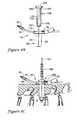
- FIG. 1is a cross-sectional view of a retractor in accordance with an embodiment of the invention used in posterior spine surgery;
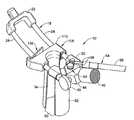
- FIG. 2is a perspective view of the retractor shown in FIG. 1 ;
- FIG. 3is a partial perspective view of the base member and rails of the retractor shown in FIG. 2 ;
- FIG. 4is a partial perspective view of the yoke or cross member and rails of the retractor shown in FIG. 2 ;
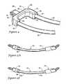
- FIG. 5Ais a side elevation view of a retractor in accordance with one embodiment of the invention and illustrating the curvature of the rails;
- FIG. 5Bis a side elevation view of a retractor in accordance with another embodiment of the invention and illustrating the curvature of the rails;
- FIG. 6is a perspective view similar to FIG. 3 but showing a blade portion coupled to the base portion;
- FIG. 6Ais a top view of the retractor shown in FIG. 2 ;
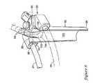
- FIG. 7is a partial perspective view of the slide of the retractor shown in FIG. 2 ;
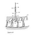
- FIGS. 8A-8Dare sequential illustration depicting the insertion of the retractor of FIG. 2 into the body of a patient;
- FIG. 9is a perspective view of an embodiment of the retractor shown in FIG. 2 but having side plates;
- FIG. 10is a partial cross-sectional view of the retractor shown in FIG. 9 ;
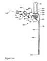
- FIG. 11is a partial cross-sectional view of the retractor similar to FIG. 9 and showing a tool for manipulating the side plate;
- FIG. 12Ais a cross-sectional view showing the coupling of a side plate and a rail in accordance to another embodiment of the invention with the plate in a first position;
- FIG. 12Bis a cross-sectional view similar to FIG. 12A but showing the side plate in an angled position.
- a surgical access systemincludes a retractor 10 that may be used during a surgical procedure to expose and provide visual and instrument access to a surgical site 12 that is spaced from an incision site 14 on a patient 16 .
- the retractor 10may be used for posterior spine surgery wherein certain spinal elements are located at the surgical site 12 and are spaced from an associated incision site 14 along the back of a patient 16 .
- the inventionis not so limited as the retractor 10 may be used in a wide variety of surgical procedures wherein the surgical site is spaced from the incision site and unencumbered access to the surgical site via the incision site is desired.
- FIG. 1is only illustrative and those of ordinary skill in the art will recognize other surgical procedures that will benefit from the present invention.
- the retractor 10may include a frame 18 including a base member 20 , and at least one, and preferably a pair of rails 24 , extending from the base member 20 .
- the framemay further include a yoke or cross member 22 opposite the base member 20 with the rails 24 extending therebetween.
- the frame 18may be positioned outside the body of the patient 16 and at a fixed location adjacent incision site 14 when used during a surgical procedure.
- the base member 20may include a generally U-shaped body 26 having a pair of leg portions 28 , 30 coupled by a connecting portion 32 and defining an inner surface 34 and an outer surface 36 .
- the inner surface 34may be generally arcuate, and in an exemplary embodiment, is generally semi-circular in shape.
- An outer face 38 of each leg portion 28 , 30includes a blind bore 40 for receiving a first end 41 of respective rails 24 .
- the rails 24may be secured to the base member 20 by a suitable fastener (not shown).
- the base member 20may include at least one threaded fastener (e.g., screw) inserted into a corresponding threaded bore (not shown) formed in a bottom surface of base member 20 so as to intersect blind bore 40 .
- the rails 24may further include apertures (not shown) to receive the threaded fasteners to thereby secure the rails 24 to the base member 20 .
- the base member 20may be coupled with the rails 24 through a molding operation, such as an overmolding process. Other processes may also be used as recognized by one of ordinary skill in the art.
- the outer surface 36 of the base member 20includes an outwardly projecting nipple 42 adapted to receive a connecting member 44 of a mounting arm 46 (which may be flexible), which is coupled to a support (e.g., operating table) and permits adjustment of the retractor 10 in relation to the patient 16 .
- the nipple 42may include at least one recess 48 adapted to receive a set screw 49 associated with the connecting member 44 to secure the mounting arm 46 to the nipple 42 .
- the base member 20may be formed of a sufficiently rigid polymer or other suitable materials as recognized by those of ordinary skill in the art. In one embodiment, the material from which base member 20 is formed may be radiolucent.
- a top surface 50 of base member 20may include one or more grooves 52 that extend between the inner and outer surfaces 34 , 36 .
- the grooves 52are adapted to receive a portion of a light assembly 54 associated with the access system and operatively coupled to a power supply (not shown) via a suitable cord 56 so as to illuminate the surgical site 12 through the retractor 10 .
- the light assembly 54may be constructed using fiber optics and a suitable light source.
- the light assembly 54may include an end having at least one, and preferably two light tubes 58 .
- Each of the light tubes 58are J-shaped with a first, relatively straight portion 60 that extends along the groove 52 in top surface 50 and a hook portion 62 that extends downwardly toward the bottom surface of base member 20 and adjacent inner surface 34 .
- the base member 20may further include a locking mechanism 64 that secures the light tubes 58 to the base member 20 .
- the locking mechanism 64includes a threaded thumb screw 66 received in a threaded bore (not shown) in the top surface 50 of base member 20 adjacent groove 52 , and a lock bar 68 received on screw 66 and configured to extend across groove 52 .
- the lock bar 68is free to rotate around screw 66 when in a loosened condition.
- the lock bar 68is positioned over the groove 52 and the thumb screw 66 tightened to prevent rotation of the lock bar 68 with respect to base member 20 .
- the lock bar 68then prevents upward movement of the light tubes 58 away from base member 20 .
- the J-shape of the light tubes 58further prevents any outward movement of the light tubes 58 away from the base member 20 .
- Multiple grooves 52may be provided to give some flexibility to the positioning of light assembly 54 with respect to the surgeon.
- the screw 66may be in a fixed position and allow the lock bar 68 rotate to an interference fit with the light tubes 58 to hold the light tubes 58 in a desired position.
- the cross member 22has a similar construction to base member 20 and includes a generally U-shaped body 70 having a pair of leg portions 72 , 74 coupled by a connecting portion 76 and defining an inner surface 78 and an outer surface 80 .
- An outer face 82 of each leg portion 72 , 74includes a blind bore 84 for receiving a second end 86 of rails 24 .
- the rails 24may be secured to the cross member 22 by a suitable fastener.
- the cross member 22may include at least one threaded fastener (e.g., screw) inserted into a corresponding threaded bore (not shown) formed in a bottom surface of cross member 22 so as to intersect blind bore 84 .
- the rails 24may further include apertures to receive the threaded fasteners to thereby secure the rails 24 to the cross member 22 .
- the yoke member 22may be coupled with the rails 24 through a molding operation, such as an overmolding process.
- Other processesmay also be used as recognized by one of ordinary skill in the art, such as screw attachment, welding, or an adhesive bond.
- the outer surface 80 of the cross member 22may include an outwardly projecting nipple 88 adapted to receive a connecting member 44 of a mounting arm 46 (see FIG. 3 ) which is coupled to a support and permits adjustment of the retractor 1 0 in relation to the patient 1 6 .
- a connecting member 44 of a mounting arm 46see FIG. 3
- Providing nipples on both sides of retractor 1 0provides some flexibility in locating the mounting arm 46 in relation to the surgeon.
- One or both nipples 42 , 88may be used to locate the retractor 10 in relation to the body.
- the nipple 88is constructed in the same manner as nipple 42 and may include at least one recess 48 adapted to receive a set screw 49 associated with the connecting member 44 to secure the mounting arm 46 to the nipple 88 .
- the cross member 22may be formed of a polymeric material, metal, or other suitable materials as recognized by those of ordinary skill in the art. In one embodiment, the material from which cross member 22 is formed may be radiolucent.
- the rails 24 of frame 12are not straight (i.e., lying along a single plane) along at least a portion of their length but rather may be generally curved from the first end 41 to the second end 86 .
- certain benefitsmay be achieved if the curvature of the rails 24 matches or otherwise corresponds to structure, such as bone structure, at the surgical site 12 .
- the curvature of rails 24may be configured to generally match the natural lordosis of the lumbar region of the spine.
- the inventionis not so limited as the curvature of the rails 24 may be configured to generally match the curvature of other regions of the spine or other structures in the body that are the focus of surgical procedures that would benefit from the invention.
- the curvature of the rails 24may be relatively constant (i.e., a portion of a circle with a specified radius of curvature) or may vary from the first end 41 to the second end 86 , depending on the specific application.
- FIG. 5Aillustrates rails 24 that curve in a continuous manner from the first end 41 to the second end 86 .
- the curvature of rails 24may be achieved through discontinuous segments, either straight or curved, that as a whole approximate a curve.
- the rails 24may be curved along at least a portion of their length and generally straight along another portion of their length.
- the rails 24may include a first generally straight, linear section 24 a and a second curved section 24 b coupled thereto that collectively define a curved path along rails 24 .
- the rails 24may have sections with different radii or a continually changing radius.
- the rails 24may be made from a wide range of suitable materials that provide sufficient rigidity to frame 12 , such as for example stainless steel, titanium, aluminum, durable plastics, or other suitable materials known to those of ordinary skill in the art.
- the retractor 10further includes a segmented tubular member 90 coupled to frame 18 and adapted to be inserted into the body of patient 16 through the incision site 14 so as to create an access path to the surgical site 12 within the body.
- the tubular member 90includes blade portions 92 , 94 capable of movement relative to each other along rails 24 to increase the effective opening of the access path. The increase in the effective opening is achieved by splitting and stretching the muscle as opposed to cutting, which provides certain advantages as previously discussed.
- the blades 92 , 94may include a taper at their distal ends that facilitate the insertion of the blades 92 , 94 through the incision and to the surgical site 12 .
- the blades 92 , 94are formed from titanium, durable polymers, and other suitable materials known to those of ordinary skill in the art.
- the blades 92 , 94may be formed from a radiolucent material.
- tubular member 90includes a first blade portion 92 having a proximal end 96 coupled to base member 20 and a distal end 98 extending away from the bottom surface of base member 20 .
- the proximal end 96 of blade portion 92is adapted to be coupled to base member 20 along inner surface 34 .
- the blade portion 92may be generally semi-circular to match the semi-circular shape of the inner surface 34 .
- the blade portion 92may be rigidly secured to base member 20 , such as through welding, fasteners such as screws, adhesives, etc. Those of ordinary skill in the art will recognize a wide range of fasteners or other ways to secure the blade portion 92 to the base member 20 .
- the base member 20 and blade portion 92may also be constructed as a unitary structure.
- the inventionis not limited to rigid securement between the blade portion 92 and the base member 20 .
- the blade portion 92may be removably secured to base member 20 . This would allow, for example, the blade portion 92 to be removed and replaced with another blade portion.
- the other blade portionmay be configured differently for use in a specific application. For instance, depending on the specific application, the length of the blade portion 92 may have to be altered. In this case, the existing blade portion could be removed and another blade portion having a shorter or longer length could be coupled to base portion 20 . Such a features facilitates the use of retractor 1 0 in a wide range of applications.
- the proximal end 96 of blade portion 92may include an outward projecting lip 99 that mates with inner surface 34 so as to form a smooth transition between the top surface 50 of base member 20 and the inner surface 100 of blade portion 92 .
- the proximal end 96 of blade portion 92may also be configured to accommodate the light tubes 58 (shown in phantom) in an improved, unobtrusive manner.
- the proximal end 96 of blade portion 92includes a notch 102 and a recess 104 formed by a tapered wall portion 106 in the wall of blade portion 92 .
- the notch 102is configured so that an upper edge of the tapered wall portion 106 forms a smooth transition with the bottom wall of groove 52 .
- the recess 104is configured to house the hook portion 62 of light tubes 58 that extend along blade portion 92 . In this way, the light tubes 58 are able to provide illumination to the surgical site without projecting into the access path created by the inner surface 100 of blade portion 92 .
- the light assembly 54does not occlude the exposure of the surgical site 12 and the possibility of hitting or catching an instrument on the light assembly 54 is eliminated or significantly reduced.
- the tapered wall portion 106not only forms the recess in which light tubes 58 are housed, but also sufficiently reflects the light generated by light tubes 58 so as to effectively illuminate the surgical site 12 .
- Tubular member 90also includes a second blade portion 94 movable relative to first blade portion 92 ( FIG. 2 ).
- the retractor 10further includes a slide 108 movably coupled to frame 18 .
- the slide 108includes a hub member 110 having a generally U-shaped body 11 2 with a pair of leg portions 114 , 116 coupled by a connecting portion 118 and defining an inner surface 120 and an outer surface 122 .
- the inner surface 120is generally arcuate, and in an exemplary embodiment, is generally semi-circular in shape.
- Each leg portion 114 , 116includes a through bore 124 for receiving rails 24 therethrough and permitting movement of the hub member 110 along rails 24 between a contracted position wherein the hub member 110 is located adjacent base member 20 and an expanded position wherein the hub member 110 is spaced from base member 20 ( FIG. 2 ).
- Each of the through bores 124may include a low-friction bushing 126 that facilitates movement of the hub member 110 along the curved rails 24 .
- the outer surface of the bushing 126is generally cylindrical and therefore is substantially straight in order to match a straight through bore 1 24 in hub member 110 .
- the inner surface of the bushing 126is curved in order to match the curvature of the rails 24 . In this way, the slide 108 moves easily along the rails 24 to facilitate enhanced use of the retractor 10 .
- slide 108further includes second blade portion 94 having a proximal end 128 coupled to hub member 110 and a distal end 130 extending away from the bottom surface of hub member 110 .
- the proximal end 128 of blade portion 94is adapted to be coupled to hub member 110 along inner surface 120 .
- the blade portion 94may be generally semi-circular to match the semi-circular shape of the inner surface 120 .
- the blade portion 94may be rigidly secured to hub member 110 or may be removably attached thereto allowing the blade portion 94 to be changed out as explained above.
- the proximal end 128 of the blade portion 94may include an outwardly projecting lip 132 that mates with inner surface 120 so as to form a smooth transition between the top surface of hub member 110 and the inner surface 134 of blade portion 94 .
- the slide 108may also include grooves in hub member 110 and a notch and recess in blade portion 94 that permits the light assembly 54 to be coupled to the access system 10 via the hub member 110 in the manner described above.
- Slide 108includes a locking mechanism 136 to selectively permit relative movement between the hub member 110 and the rails 24 .
- the hub member 110includes a J-shaped tab 138 positioned outside and adjacent rail 24 and extending away from the outer surface 122 of hub member 110 to define a groove or channel 140 between the tab 138 and outer surface 122 .
- the locking mechanism 136includes a lock bar 142 having a first end 144 a second end 146 , and an aperture 148 therein positioned adjacent first end 144 and adapted to receive rail 24 therethrough.
- the first end 144 of lock bar 142is positioned in channel 140 when the rail 24 passes through aperture 148 and operates as a pivot point about which lock bar 142 may pivot.
- the lock bar 142is pivotable between an open position wherein the rail 24 slides freely through the aperture 148 and a closed or locked position, where engagement between the aperture 148 and the rail 24 prevents relative movement of the hub member 110 relative to rail 24 and thus, locks the slide 108 to the frame 12 .
- the hub member 110may be freely moved along the rails 24 , such as through a manual process, so as to separate the second blade portion 94 from the first blade portion 92 .
- the rail 24is canted with respect to the lock bar 142 so that a portion of the aperture 148 engages with a portion of the rail 24 to prevent any relative movement therebetween.
- the lock bar 142is biased toward the locked position.
- the outer surface 122 of the hub member 110may include a bore 150 adapted to receive a spring 152 that engages the lock bar 142 so as to bias the lock bar 142 toward the locked position.
- the locking mechanism 136as described above may also operate as a one-way lock where moving the slide 108 away from the base member 20 automatically opens the lock bar 142 without the application of an operator's force on the second end 146 of lock bar 142 . When the slide 108 stops moving away from the base member 20 , the locking mechanism 136 automatically locks to the rail 24 and any movement of the slide 108 back toward the base member 20 is prevented.
- an incisionis made, for example in the skin, to form an incision site 14 proximate to an intended surgical site 12 .
- guide wire 154such as a k-wire, is inserted into the incision site 14 , through the tissue, and to the surgical site 12 to establish a pathway from the incision site 14 to the surgical site 12 .
- a guide rod 156is threaded onto the guide wire 154 and through the incision site 14 .
- the guide rod 156may be inserted through the incision site 14 without the use of the guide wire 154 .
- the guide rod 156is configured to create an opening through the tissue between the incision site 14 and the surgical site 12 by splitting and stretching the tissue as opposed to cutting the tissue.
- the guide rod 156includes a generally cylindrical elongated body 158 having a central passage 159 through which the guide wire 154 extends, a proximal end 160 is adapted to be outside the body and a distal end 162 is adapted to be positioned near the surgical site 12 .
- the proximal end 160includes annular ridges 164 to facilitate gripping by a surgeon or other medical professional to work the guide rod 156 through the tissue and toward the surgical site 12 .
- the distal end 162includes an enlarged tip portion 166 whose purpose is explained in more detail below.
- the tip portion 166includes a tapered region 167 to facilitate insertion of the guide rod 156 through the tissue.
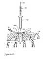
- the obturator 168includes a generally cylindrical elongated body 170 having a central passage 172 through which the guide rod 156 extends, a proximal end 174 adapted to be outside the body, and a distal end 176 adapted to be positioned at or near the surgical site 12 .
- the proximal end 174includes an annular flange 178 extending radially outward from body 170 to define a shoulder 180 .
- the distal end 176 of obturator 168includes a tapered region 182 to facilitate insertion of the obturator 168 through the tissue and to the surgical site 12 .
- the obturator 168is coupled to the frame 12 and tubular member 90 so as to position the retractor 10 within the body during the second insertion step.
- the hub member 110is positioned in its contracted position so as to be adjacent base member 20 .
- the first and second blade portions 92 , 94cooperate to generally form a closed cylindrical tube.
- the inner diameter of the of the tube formed by the inner surfaces 100 , 134 of blade portions 92 , 94is slightly larger than the outer diameter of the elongated body 170 of obturator 168 and thus obturator 168 may be inserted therein.
- the flange 178 on obturator 168is larger than the inner diameter of the cylindrical tube and thus contacts the top surfaces of the base member 20 and hub member 110 along shoulder 180 .
- the distal end 176extends beyond the distal ends 98 , 130 of blade portions 92 , 94 , as shown in FIG. 8C .
- the distal ends 98 , 130 of blade portions 92 , 94are located at, or proximal of, tapered region 182 so as to provide a smooth transition between the increasingly larger components of retractor 10 .
- the obturator 168 and retractor 10are inserted through the incision site 14 using the guide rod 156 as a guide so as to properly locate the retractor 10 within the body of the patient 16 .
- the guide rod 156 and obturator 168may then be removed from the body leaving only the retractor 10 .
- the distal end 176 of obturator 168is proximal of the enlarged tip portion 166 of guide rod 156 . In this way, and as shown in FIG.
- the slide 108may be moved to increase the effective opening at the incision site 14 .
- a pliers-type toolas is known in the art, may be used to move the hub member 110 away from the base member 20 from its contracted position to an expanded position thereby moving the second blade portion 94 relative to the first blade portion 92 to increase the opening at the incision site 14 .
- the retractor 10 in an expanded positionis shown in FIG. 8D . Once in the expanded position, the locking mechanism 136 on the hub member 110 locks the hub member 110 and the second blade portion 94 along rail 24 as explained above.
- the movement of the slide 108 along the curved rails 24provides certain benefits not achieved in some prior art devices.
- the curvature of the railsapproximates the curvature of the spine in, for example, the lumbar region
- the relative distance between the distal end of the second blade portion 94 and the bone structure of the spineis maintained even as the slide 108 is moved along the rails 24 .
- maintaining the spacing between the distal end of the second blade portion 94 and the spineprevents any surrounding tissue from creeping into the access path or working space which would otherwise occlude exposure of the surgical site 12 .
- the curvature of the rails 24provides an additional benefit. Due to the curvature of the rails 24 , as the slide 108 moves along the curved rails 24 , the access path created by first and second blade portions 92 , 94 no longer has straight walls, e.g., a cross dimension spanning from the first blade 92 to the second blade 94 that remains constant from the incision site to the surgical site. Instead, because the second blade portion 94 remains substantially perpendicular to the rail 24 , and rail 24 is curved, the second blade portion 92 becomes angled with respect to the first blade portion 92 so that the cross dimension spanning from the first blade 92 to the second blade 94 progressively increases in a direction from the incision site 14 to the surgical site 12 .
- Such a configurationmaintains a minimized cross dimension between the blades 92 , 94 near the incision site 14 but increases the cross dimension in a direction toward the surgical site 12 .
- the minimal invasiveness of the surgical proceduremay be maintained while enhancing the exposure of the surgical site 12 away from the incision site 14 .
- the diverging configuration of the second blade portion 94 as described above, that results from the curvature of the rails 24also provides a mechanism for preventing the surrounding tissue, which has been displaced by movement of second blade portion 94 , from forcing the retractor 10 away from the surgical site 12 .
- the surrounding tissueimposes a net force on the second blade portion 94 in the direction of the surgical site 12 .
- the surrounding tissueimposes forces that, in essence, maintain the position of the retractor 10 in relation to the surgical site 12 . This then eliminates or reduces any external forces necessary to maintain the position of the retractor 10 within the body.
- the retractor 10may further include side plates 190 , 192 adapted to be mounted to rails 24 to prevent or reduce the encroachment of surrounding tissue into the access path through gaps 184 . As the construction and operation of side plates 190 , 192 are substantially the same, only side plate 190 will be described in detail herein.
- side plate 190includes a generally flat, elongated body 194 having an inner surface 196 adapted to form part of the access path, an outer surface 198 adapted to face the surrounding tissue, a proximal end 200 adapted to be adjacent rail 24 , a distal end 202 adapted to be positioned through the incision site 14 and towards the surgical site 12 , and a pair of side edges 204 extending between the proximal and distal ends 200 , 202 .
- a cross-dimension of the side plate 190may be configured to correspond to the shape of the gap 184 between the two blade portions 92 , 94 when in the expanded position ( FIG. 9 ).
- the cross-dimension of the side plate 190may increase in a direction from the proximal end 200 to the distal end 202 .
- the length of the side plate 190may correspond to the length of the side edges 186 , 188 of blades 92 , 94 .
- the inventionis not so limited as a shorter or longer side plate 190 may be used depending on the specific application.
- the proximal end 200 of side plate 190includes a mounting member 206 for mounting the side plate 190 on rail 24 .
- the mounting member 206has a J-shaped configuration with a top leg 208 coupled to and extending generally perpendicular to body 194 and a down-turned flange 210 coupled to top leg 208 and extending toward distal end 202 .
- the J-shaped mounting member 206defines an engagement region 212 bounded by the body 194 , top leg 208 , and down-turned flange 210 , and adapted to receive the rail 24 therein.
- the outer surface 198 of slide plate 190includes a projecting rib 214 that partially bounds a bearing surface 216 having a shape that corresponds to the shape of a portion of the rail 24 .
- the bearing surface 216may be semi-circular in shape so as to closely receive a portion of the circumference of rail 24 .
- the rib 214also cooperates with down-turned flange 210 to define an opening 218 to engagement region 212 that is larger than the cross dimension (e.g., diameter) of the rail 24 so as to permit the rail 24 to pass into the region 212 and bear against bearing surface 216 .
- the proximal end 200 of side plate 190is positioned between blade portions 92 , 94 when in an expanded position and adjacent rail 24 so that rail 24 passes through the opening 218 and is seated against bearing surface 216 .
- Side plate 190further includes an attachment member that secures the side plate 190 to the rail 24 .
- the attachment memberincludes a set screw 220 for securing the side plate 190 to rail 24 .
- the down-turned flange 210includes an aperture 222 therethrough and aligned along an axis 224 that intersects the bearing surface 216 in the engagement region 212 .
- the aperture 222includes internal threads (not shown).
- the set screw 220includes a proximal end 228 defining a head 230 and a distal end 232 defining a contacting surface 234 .
- Set screw 220further includes external threads (not shown).
- the internal threads of aperture 222cooperate with external threads on screw 220 such that rotation of the screw 220 in a first direction causes the screw 220 to advance along axis 224 , moving contacting surface 234 toward bearing surface 216 . Rotation of the screw 220 in an opposite direction causes the screw to withdraw along axis 224 , moving contacting surface 234 away from bearing surface 216 . In this way, the set screw 220 may be in a release position allowing the rail 24 to pass through opening 218 and to be seated in bearing surface 216 .
- the set screw 220may then be moved to an engaged position by rotating the set screw in the first direction so that the contacting surface 234 contacts the rail 24 and sufficiently compresses the rail 24 between the contacting and bearing surfaces 234 , 216 to prevent relative movement between the side plate 190 and rail 24 .
- a suitable tool 238may be used to rotate the set screw 220 between the release and engaged positions.
- the tool 238may include a connector portion 240 and a handle portion 242 .
- the connector portion 240cooperates with head 230 such that rotation of the tool 238 rotates the set screw 220 .
- the connector portion 240may include one or more ribs (not shown) that engage one or more flats 244 on the head 230 .
- the handle portion 242is configured to be easily grasped by a surgeon or other medical professional for rotating the tool 238 in order to advance or withdraw the set screw 220 .
- the side plate 190is permitted to rotate about the rails 24 illustrated by arrow A when the set screw 220 is not in the engaged position.
- the side plate 190is free to continuously rotate about the rail 24 to effectively define an infinite number of angular positions of side plate 190 relative to rail 24 .
- the side plate 190defines a first position where the edges 186 , 188 of blade portions 92 , 94 and the side edges 204 of the side plate 190 lie in the same plane. This is shown in FIG. 9 and in phantom in FIG. 11 .
- both side plates 190 , 192When both side plates 190 , 192 are in the first position, the side plates 190 , 192 cooperate with blade portions 92 , 94 to define a substantially enclosed circumference along at least a portion of the access path between the proximal and distal ends of the blade portions ( FIG. 9 ).
- the side blades 190 , 192may be rotated on rails 24 to an angled position and then secured to the rails 24 using set screw 220 to maintain the angled position, as illustrated in FIG. 11 .
- the side plates 190 , 192may be rotated outwardly and away from each other such that a cross dimension between the two plates 190 , 192 at the incision site 14 is minimized, while the cross dimension between the two plates 190 , 192 increases in a direction from the incision site 14 to the surgical site 12 to increase the exposure of the surgical site 12 .
- side platesmay be used on just one or both rails 24 .
- tool 238may also be used to rotate the side plates 190 , 192 to their desired angular positions.
- set screw 220may include an attachment member 246 and the tool 238 may also include an attachment member (not shown) that cooperate to provide a secure coupling between the tool 238 and set screw 220 .
- the attachment member 246may be a quick-release type of connection that allows the tool 238 to be removed once the desired angular position is reached.
- the tool 238may be used to both rotate the side plates 190 , 192 about rails 24 , by providing a secure coupling to set screw 220 , and to secure the side plates 190 , 192 to the rails 24 by advancing/withdrawing the set screw 220 as explained above.
- the side plates 190 , 192may be secured in various angular positions in other ways.
- the engagement region 212my include a pair of generally parallel, opposed walls 248 , 250 that cooperate with opposed flats on rails 24 .
- the side plates 190 , 192are in the first position (i.e., aligned with blade portions 92 , 94 ), shown in FIG. 12A , the walls 248 , 250 engage flats 252 on rail 24 and rotation of the side plates 190 , 192 is prevented.
- Flatsmay also be provided on rails 24 to position the plates 190 , 192 in an angled position.
- flats 254may be provided such that engagement of the walls 248 , 250 with flats 254 places the side plates in an angled position.
- only a discrete number of angular positions of the side platesmay be provided in this manner.
- the side platesmay, in essence, substantially close the gaps 184 between the blade portions and prevent or reduce the likelihood of tissue creeping into the access path and occluding the exposure of the surgical site.
- a single side platemay be used or multiple side plates may be positioned on each of the rails 24 .
- a plethora of the side platesmay be provided with each side plate having a different cross dimension to accommodate different size gaps.
- a plethora of side platesmay also be provided with each side plate having a different length.
- the inventionis not limited to the number, size, geometry, etc. of the side plates as those of ordinary skill in the art recognize that the plates may be configured to suit a particular surgical application.
Landscapes
- Health & Medical Sciences (AREA)
- Life Sciences & Earth Sciences (AREA)
- Surgery (AREA)
- Heart & Thoracic Surgery (AREA)
- Engineering & Computer Science (AREA)
- Biomedical Technology (AREA)
- Nuclear Medicine, Radiotherapy & Molecular Imaging (AREA)
- Medical Informatics (AREA)
- Molecular Biology (AREA)
- Animal Behavior & Ethology (AREA)
- General Health & Medical Sciences (AREA)
- Public Health (AREA)
- Veterinary Medicine (AREA)
- Surgical Instruments (AREA)
Abstract
Description
Claims (19)
Priority Applications (3)
| Application Number | Priority Date | Filing Date | Title |
|---|---|---|---|
| US11/619,214US8262569B2 (en) | 2006-07-19 | 2007-01-03 | Surgical access system and method of using the same |
| US11/623,937US7892174B2 (en) | 2006-07-19 | 2007-01-17 | Surgical access system and method of using the same |
| PCT/US2007/067461WO2008011207A2 (en) | 2006-07-19 | 2007-04-26 | Surgical access system and method of using the same |
Applications Claiming Priority (2)
| Application Number | Priority Date | Filing Date | Title |
|---|---|---|---|
| US45866206A | 2006-07-19 | 2006-07-19 | |
| US11/619,214US8262569B2 (en) | 2006-07-19 | 2007-01-03 | Surgical access system and method of using the same |
Related Parent Applications (1)
| Application Number | Title | Priority Date | Filing Date |
|---|---|---|---|
| US45866206AContinuation-In-Part | 2006-07-19 | 2006-07-19 |
Related Child Applications (1)
| Application Number | Title | Priority Date | Filing Date |
|---|---|---|---|
| US11/623,937Continuation-In-PartUS7892174B2 (en) | 2006-07-19 | 2007-01-17 | Surgical access system and method of using the same |
Publications (2)
| Publication Number | Publication Date |
|---|---|
| US20080161650A1 US20080161650A1 (en) | 2008-07-03 |
| US8262569B2true US8262569B2 (en) | 2012-09-11 |
Family
ID=39584964
Family Applications (1)
| Application Number | Title | Priority Date | Filing Date |
|---|---|---|---|
| US11/619,214Expired - Fee RelatedUS8262569B2 (en) | 2006-07-19 | 2007-01-03 | Surgical access system and method of using the same |
Country Status (1)
| Country | Link |
|---|---|
| US (1) | US8262569B2 (en) |
Cited By (7)
| Publication number | Priority date | Publication date | Assignee | Title |
|---|---|---|---|---|
| USD846119S1 (en) | 2017-01-24 | 2019-04-16 | Medtronic Advanced Energy Llc | Lighted surgical retractor base |
| US10736618B2 (en) | 2017-01-24 | 2020-08-11 | Medtronic Advanced Energy Llc | Modular lighted surgical retractor |
| USD956224S1 (en) | 2020-05-12 | 2022-06-28 | Innovasis, Inc. | Surgical retractor |
| USD956225S1 (en) | 2020-05-12 | 2022-06-28 | Innovasis, Inc. | Surgical retractor |
| USD956223S1 (en) | 2020-05-12 | 2022-06-28 | Innovasis, Inc. | Surgical retractor |
| US11432810B2 (en) | 2020-05-12 | 2022-09-06 | Innovasis, Inc. | Systems and methods for surgical retraction |
| US20240350130A1 (en)* | 2023-04-19 | 2024-10-24 | Life Spine, Inc. | Micro Retractor |
Families Citing this family (9)
| Publication number | Priority date | Publication date | Assignee | Title |
|---|---|---|---|---|
| CN102448379B (en) | 2009-04-03 | 2014-11-19 | 米切尔·A·哈登布鲁克 | Surgical retractor system |
| US8956284B2 (en)* | 2011-01-20 | 2015-02-17 | K2M, Inc. | Minimally invasive retractor and posted screw |
| US20120310351A1 (en)* | 2011-06-02 | 2012-12-06 | Farley Daniel K | Lordotic spacer |
| US8795167B2 (en) | 2011-11-15 | 2014-08-05 | Baxano Surgical, Inc. | Spinal therapy lateral approach access instruments |
| FR3012030B1 (en)* | 2013-10-18 | 2015-12-25 | Medicrea International | METHOD FOR REALIZING THE IDEAL CURVATURE OF A ROD OF A VERTEBRAL OSTEOSYNTHESIS EQUIPMENT FOR STRENGTHENING THE VERTEBRAL COLUMN OF A PATIENT |
| US10786328B2 (en)* | 2016-10-26 | 2020-09-29 | Thompson Surgical Instruments, Inc. | Adaptor handle for surgical retractor |
| US11944356B2 (en) | 2019-11-22 | 2024-04-02 | Medos International Sarl | Control member for adjusting access tube position, and related systems and methods |
| US11759193B2 (en)* | 2019-12-20 | 2023-09-19 | Medos International Sarl | Retractor members, and related systems and methods |
| CN115024772B (en)* | 2022-06-14 | 2023-03-10 | 青岛钰仁医疗科技有限公司 | Double-channel spine minimally invasive surgery system, control method and channel tube device |
Citations (76)
| Publication number | Priority date | Publication date | Assignee | Title |
|---|---|---|---|---|
| US402068A (en)* | 1889-04-23 | crannell | ||
| US421814A (en)* | 1890-02-18 | Densmore j | ||
| US1375445A (en)* | 1917-04-02 | 1921-04-19 | Elijah R Crossley | Apparatus for use in surgical operations on the eye |
| US1963173A (en)* | 1933-01-03 | 1934-06-19 | Horace Lauzon | Retractor |
| US2473266A (en)* | 1946-06-12 | 1949-06-14 | David J Wexler | Self-retaining abdominal retractor |
| US2812759A (en)* | 1956-06-21 | 1957-11-12 | Harry R Taylor | Abdominal retractor |
| US3509873A (en)* | 1967-04-24 | 1970-05-05 | Jack B Karlin | Retractor |
| US3572326A (en)* | 1968-05-06 | 1971-03-23 | Medic Made Inc | Chest wall retractor |
| US3724449A (en)* | 1970-10-19 | 1973-04-03 | W Gauthier | Retractor apparatus |
| US4813401A (en)* | 1986-11-26 | 1989-03-21 | Grieshaber Manufacturing Company | Retractor |
| US5088472A (en)* | 1990-04-04 | 1992-02-18 | Mehdi Fakhrai | Retractor |
| US5293863A (en) | 1992-05-08 | 1994-03-15 | Loma Linda University Medical Center | Bladed endoscopic retractor |
| US5299563A (en)* | 1992-07-31 | 1994-04-05 | Seton Joseph Z | Method of using a surgical retractor |
| US5503617A (en)* | 1994-07-19 | 1996-04-02 | Jako; Geza J. | Retractor and method for direct access endoscopic surgery |
| US5520610A (en)* | 1991-05-31 | 1996-05-28 | Giglio; Steven R. | Self retaining retractor |
| US5616117A (en)* | 1995-08-03 | 1997-04-01 | Ohio Medical Instrument Company, Inc. | Self locking surgical retractor |
| US5667481A (en) | 1995-02-01 | 1997-09-16 | Villalta; Josue J. | Four blade medical retractor |
| US5697891A (en)* | 1997-01-06 | 1997-12-16 | Vista Medical Technologies, Inc. | Surgical retractor with accessory support |
| US5728046A (en) | 1995-06-23 | 1998-03-17 | Aesculap Ag | Surgical retractor |
| US5779629A (en)* | 1997-10-02 | 1998-07-14 | Hohlen; Robert D. | Dual axis retractor |
| US5792044A (en) | 1996-03-22 | 1998-08-11 | Danek Medical, Inc. | Devices and methods for percutaneous surgery |
| US5902233A (en)* | 1996-12-13 | 1999-05-11 | Thompson Surgical Instruments, Inc. | Angling surgical retractor apparatus and method of retracting anatomy |
| US5928139A (en) | 1998-04-24 | 1999-07-27 | Koros; Tibor B. | Retractor with adjustable length blades and light pipe guides |
| US5938592A (en) | 1997-01-31 | 1999-08-17 | Rultract, Inc. | Surgical support apparatus with adjustable rakes and rake plate and method of use |
| US5944658A (en)* | 1997-09-23 | 1999-08-31 | Koros; Tibor B. | Lumbar spinal fusion retractor and distractor system |
| US5967972A (en) | 1997-03-28 | 1999-10-19 | Kapp Surgical Instrument, Inc. | Minimally invasive surgical retractor and method of operation |
| US5984865A (en)* | 1998-09-15 | 1999-11-16 | Thompson Surgical Instruments, Inc. | Surgical retractor having locking interchangeable blades |
| US6083154A (en)* | 1997-10-23 | 2000-07-04 | Sofamor S.N.C. | Surgical instrumentation and method for retracting and shifting tissues |
| US6099547A (en) | 1997-02-13 | 2000-08-08 | Scimed Life Systems, Inc. | Method and apparatus for minimally invasive pelvic surgery |
| US6187000B1 (en) | 1998-08-20 | 2001-02-13 | Endius Incorporated | Cannula for receiving surgical instruments |
| US6190312B1 (en)* | 1999-03-04 | 2001-02-20 | Lone Star Medical Products, Inc. | Variable geometry retractor and disposable retractor stay clips and method of use |
| US6224545B1 (en)* | 1998-07-24 | 2001-05-01 | Core Surgical, Inc. | Surgical retractor and method for use |
| US20010007052A1 (en)* | 1998-01-23 | 2001-07-05 | Person Wayne C. | Surgical instrument holder |
| US6264605B1 (en)* | 1998-01-23 | 2001-07-24 | United States Surgical Corporation | Surgical instrument |
| US6280379B1 (en)* | 1999-12-02 | 2001-08-28 | Scott Resnick | Speculum |
| EP1192905A1 (en) | 2000-10-02 | 2002-04-03 | Aesculap AG & Co. KG | Surgical retractor |
| US6371968B1 (en) | 1996-05-09 | 2002-04-16 | Olympus Optical Co., Ltd. | Cavity retaining tool for bone surgery, a cavity retaining tool for general surgery, an endoscopic surgery system involving the use of a cavity retaining tool, and a procedure for surgery |
| US20020128659A1 (en) | 2001-03-01 | 2002-09-12 | Michelson Gary K. | Dynamic lordotic guard with movable extensions for creating an implantation space posteriorly in the lumbar spine and method for use thereof |
| US6464634B1 (en) | 2000-09-27 | 2002-10-15 | Depuy Acromed, Inc. | Surgical retractor system |
| US20020177753A1 (en)* | 2001-05-25 | 2002-11-28 | Minnesota Scientific, Inc. | Multi-position spherical retractor holder |
| US20030149341A1 (en)* | 2002-02-06 | 2003-08-07 | Clifton Guy L. | Retractor and/or distractor for anterior cervical fusion |
| US20030191371A1 (en) | 2002-04-05 | 2003-10-09 | Smith Maurice M. | Devices and methods for percutaneous tissue retraction and surgery |
| US20030199874A1 (en) | 2001-03-01 | 2003-10-23 | Michelson Gary K. | Dynamic lordotic guard with movable extensions for creating an implantation space posteriorly in the lumbar spine and method for use thereof |
| WO2004006778A1 (en) | 2002-07-11 | 2004-01-22 | Fanous Refaat S | Self-retaining retractor |
| US20040024291A1 (en) | 2002-08-01 | 2004-02-05 | Zinkel John L. | Method and apparatus for spinal surgery |
| US6712795B1 (en)* | 2002-06-07 | 2004-03-30 | Lester Cohen | Surgical procedure and apparatus |
| US20040087833A1 (en) | 2002-10-30 | 2004-05-06 | Thomas Bauer | Retractor |
| US20040093001A1 (en) | 2002-10-25 | 2004-05-13 | Hamada James S. | Minimal access lumbar diskectomy instrumentation and method |
| US20040127773A1 (en)* | 2002-12-31 | 2004-07-01 | Ethicon, Inc. | Curved rack retractor |
| US20040147812A1 (en) | 2002-10-02 | 2004-07-29 | Hamel Ross J. | Retractor with interchangeable retractor blades |
| US20040176665A1 (en) | 2002-06-26 | 2004-09-09 | Branch Charles L. | Instruments and methods for minimally invasive tissue retraction and surgery |
| US6793656B1 (en) | 1992-03-17 | 2004-09-21 | Sdgi Holdings, Inc. | Systems and methods for fixation of adjacent vertebrae |
| US20040230100A1 (en) | 2003-05-16 | 2004-11-18 | Shluzas Alan E. | Access device for minimally invasive surgery |
| US20040236317A1 (en) | 2000-08-01 | 2004-11-25 | Davison Thomas W. | Method of securing vertebrae |
| US20050038440A1 (en) | 2002-12-13 | 2005-02-17 | Jeffrey Larson | Guided retractor and methods of use |
| US20050043742A1 (en) | 2003-08-21 | 2005-02-24 | Aurelian Bruneau | Systems and methods for positioning implants relative to bone anchors in surgical approaches to the spine |
| US6869398B2 (en) | 2003-01-06 | 2005-03-22 | Theodore G. Obenchain | Four-blade surgical speculum |
| US20050080320A1 (en) | 2003-08-14 | 2005-04-14 | Lee Andrew Max | Multiple-blade retractor |
| US20050137461A1 (en) | 2003-12-18 | 2005-06-23 | Depuy Spine, Inc. | Telescoping blade assembly and instruments for adjusting an adjustable blade |
| US20050149035A1 (en) | 2003-10-17 | 2005-07-07 | Nuvasive, Inc. | Surgical access system and related methods |
| US20050159651A1 (en)* | 2003-12-18 | 2005-07-21 | Depuy Spine, Inc. | Surgical retractor systems and illuminated cannulae |
| US20050165283A1 (en) | 2003-01-31 | 2005-07-28 | Zimmer Technology, Inc. | Lit retractor |
| US20050177028A1 (en)* | 2002-04-26 | 2005-08-11 | Research Surgical Pty Ltd | Retractor |
| US20050203625A1 (en) | 2000-11-13 | 2005-09-15 | Boehm Frank H.Jr. | Device and method for lumbar interbody fusion |
| US20050215866A1 (en) | 2004-03-25 | 2005-09-29 | Depuy Spine, Inc. | Surgical retractor positioning device |
| US20050234304A1 (en)* | 2002-06-26 | 2005-10-20 | Sdgi Holdings, Inc. | Instruments and methods for minimally invasive tissue retraction and surgery |
| US20050245928A1 (en) | 2004-05-03 | 2005-11-03 | Innovative Spinal Technologies | System and method for displacement of bony structures |
| US20050277812A1 (en)* | 2004-06-14 | 2005-12-15 | Myles Robert T | Minimally invasive surgical spinal exposure system |
| US20060004401A1 (en) | 2004-06-30 | 2006-01-05 | Abernathie Dennis L | Elongateable surgical port and dilator |
| US20060069315A1 (en) | 2003-09-25 | 2006-03-30 | Patrick Miles | Surgical access system and related methods |
| US7041055B2 (en) | 2002-10-07 | 2006-05-09 | Mark LoGuidice | Instruments and methods for use in laparoscopic surgery |
| US20060106416A1 (en) | 2004-10-29 | 2006-05-18 | Douglas Raymond | Expandable ports and methods for minimally invasive surgery |
| US20060229636A1 (en) | 2005-03-04 | 2006-10-12 | Woodburn William N Sr | Expandable access device with mobility member |
| US20060235279A1 (en) | 2005-03-18 | 2006-10-19 | Hawkes David T | Less invasive access port system and method for using the same |
| US20060271096A1 (en)* | 2002-10-25 | 2006-11-30 | Hamada James S | Minimal incision maximal access MIS spine instrumentation and method |
| US20090203969A1 (en)* | 2006-11-09 | 2009-08-13 | Cohen Dan S | Surgical retractor device and related methods |
- 2007
- 2007-01-03USUS11/619,214patent/US8262569B2/ennot_activeExpired - Fee Related
Patent Citations (87)
| Publication number | Priority date | Publication date | Assignee | Title |
|---|---|---|---|---|
| US402068A (en)* | 1889-04-23 | crannell | ||
| US421814A (en)* | 1890-02-18 | Densmore j | ||
| US1375445A (en)* | 1917-04-02 | 1921-04-19 | Elijah R Crossley | Apparatus for use in surgical operations on the eye |
| US1963173A (en)* | 1933-01-03 | 1934-06-19 | Horace Lauzon | Retractor |
| US2473266A (en)* | 1946-06-12 | 1949-06-14 | David J Wexler | Self-retaining abdominal retractor |
| US2812759A (en)* | 1956-06-21 | 1957-11-12 | Harry R Taylor | Abdominal retractor |
| US3509873A (en)* | 1967-04-24 | 1970-05-05 | Jack B Karlin | Retractor |
| US3572326A (en)* | 1968-05-06 | 1971-03-23 | Medic Made Inc | Chest wall retractor |
| US3724449A (en)* | 1970-10-19 | 1973-04-03 | W Gauthier | Retractor apparatus |
| US4813401A (en)* | 1986-11-26 | 1989-03-21 | Grieshaber Manufacturing Company | Retractor |
| US5088472A (en)* | 1990-04-04 | 1992-02-18 | Mehdi Fakhrai | Retractor |
| US5520610A (en)* | 1991-05-31 | 1996-05-28 | Giglio; Steven R. | Self retaining retractor |
| US6793656B1 (en) | 1992-03-17 | 2004-09-21 | Sdgi Holdings, Inc. | Systems and methods for fixation of adjacent vertebrae |
| US5293863A (en) | 1992-05-08 | 1994-03-15 | Loma Linda University Medical Center | Bladed endoscopic retractor |
| US5299563A (en)* | 1992-07-31 | 1994-04-05 | Seton Joseph Z | Method of using a surgical retractor |
| US5813978A (en)* | 1994-07-19 | 1998-09-29 | Atlantis Surgical, Inc. | Method and apparatus for direct access endoscopic surgery |
| US5503617A (en)* | 1994-07-19 | 1996-04-02 | Jako; Geza J. | Retractor and method for direct access endoscopic surgery |
| US5667481A (en) | 1995-02-01 | 1997-09-16 | Villalta; Josue J. | Four blade medical retractor |
| US5728046A (en) | 1995-06-23 | 1998-03-17 | Aesculap Ag | Surgical retractor |
| US5616117A (en)* | 1995-08-03 | 1997-04-01 | Ohio Medical Instrument Company, Inc. | Self locking surgical retractor |
| US6520907B1 (en) | 1996-03-22 | 2003-02-18 | Sdgi Holdings, Inc. | Methods for accessing the spinal column |
| US5792044A (en) | 1996-03-22 | 1998-08-11 | Danek Medical, Inc. | Devices and methods for percutaneous surgery |
| US6371968B1 (en) | 1996-05-09 | 2002-04-16 | Olympus Optical Co., Ltd. | Cavity retaining tool for bone surgery, a cavity retaining tool for general surgery, an endoscopic surgery system involving the use of a cavity retaining tool, and a procedure for surgery |
| US5902233A (en)* | 1996-12-13 | 1999-05-11 | Thompson Surgical Instruments, Inc. | Angling surgical retractor apparatus and method of retracting anatomy |
| US5697891A (en)* | 1997-01-06 | 1997-12-16 | Vista Medical Technologies, Inc. | Surgical retractor with accessory support |
| US5938592A (en) | 1997-01-31 | 1999-08-17 | Rultract, Inc. | Surgical support apparatus with adjustable rakes and rake plate and method of use |
| US6099547A (en) | 1997-02-13 | 2000-08-08 | Scimed Life Systems, Inc. | Method and apparatus for minimally invasive pelvic surgery |
| US5967972A (en) | 1997-03-28 | 1999-10-19 | Kapp Surgical Instrument, Inc. | Minimally invasive surgical retractor and method of operation |
| US6361492B1 (en)* | 1997-03-28 | 2002-03-26 | Kapp Surgical Instrument, Inc. | Surgical stabilizer |
| US5944658A (en)* | 1997-09-23 | 1999-08-31 | Koros; Tibor B. | Lumbar spinal fusion retractor and distractor system |
| US5779629A (en)* | 1997-10-02 | 1998-07-14 | Hohlen; Robert D. | Dual axis retractor |
| US6083154A (en)* | 1997-10-23 | 2000-07-04 | Sofamor S.N.C. | Surgical instrumentation and method for retracting and shifting tissues |
| US6264605B1 (en)* | 1998-01-23 | 2001-07-24 | United States Surgical Corporation | Surgical instrument |
| US20010007052A1 (en)* | 1998-01-23 | 2001-07-05 | Person Wayne C. | Surgical instrument holder |
| US5928139A (en) | 1998-04-24 | 1999-07-27 | Koros; Tibor B. | Retractor with adjustable length blades and light pipe guides |
| US6224545B1 (en)* | 1998-07-24 | 2001-05-01 | Core Surgical, Inc. | Surgical retractor and method for use |
| US6187000B1 (en) | 1998-08-20 | 2001-02-13 | Endius Incorporated | Cannula for receiving surgical instruments |
| US6811558B2 (en) | 1998-08-20 | 2004-11-02 | Endius Incorporated | Method for performing a surgical procedure and a cannula for use in performing the surgical procedure |
| US5984865A (en)* | 1998-09-15 | 1999-11-16 | Thompson Surgical Instruments, Inc. | Surgical retractor having locking interchangeable blades |
| US6190312B1 (en)* | 1999-03-04 | 2001-02-20 | Lone Star Medical Products, Inc. | Variable geometry retractor and disposable retractor stay clips and method of use |
| US6280379B1 (en)* | 1999-12-02 | 2001-08-28 | Scott Resnick | Speculum |
| US20040236317A1 (en) | 2000-08-01 | 2004-11-25 | Davison Thomas W. | Method of securing vertebrae |
| US6464634B1 (en) | 2000-09-27 | 2002-10-15 | Depuy Acromed, Inc. | Surgical retractor system |
| EP1192905A1 (en) | 2000-10-02 | 2002-04-03 | Aesculap AG & Co. KG | Surgical retractor |
| US20050203625A1 (en) | 2000-11-13 | 2005-09-15 | Boehm Frank H.Jr. | Device and method for lumbar interbody fusion |
| US20020128659A1 (en) | 2001-03-01 | 2002-09-12 | Michelson Gary K. | Dynamic lordotic guard with movable extensions for creating an implantation space posteriorly in the lumbar spine and method for use thereof |
| US20050043741A1 (en) | 2001-03-01 | 2005-02-24 | Michelson Gary K. | Retractor for percutaneous surgery in a patient and method for use thereof |
| US20030199874A1 (en) | 2001-03-01 | 2003-10-23 | Michelson Gary K. | Dynamic lordotic guard with movable extensions for creating an implantation space posteriorly in the lumbar spine and method for use thereof |
| US20020177753A1 (en)* | 2001-05-25 | 2002-11-28 | Minnesota Scientific, Inc. | Multi-position spherical retractor holder |
| US20030149341A1 (en)* | 2002-02-06 | 2003-08-07 | Clifton Guy L. | Retractor and/or distractor for anterior cervical fusion |
| US20030191371A1 (en) | 2002-04-05 | 2003-10-09 | Smith Maurice M. | Devices and methods for percutaneous tissue retraction and surgery |
| US20050177028A1 (en)* | 2002-04-26 | 2005-08-11 | Research Surgical Pty Ltd | Retractor |
| US6712795B1 (en)* | 2002-06-07 | 2004-03-30 | Lester Cohen | Surgical procedure and apparatus |
| US20050192485A1 (en) | 2002-06-26 | 2005-09-01 | Branch Charles L. | Instruments and methods for minimally invasive tissue retraction and surgery |
| US20050234304A1 (en)* | 2002-06-26 | 2005-10-20 | Sdgi Holdings, Inc. | Instruments and methods for minimally invasive tissue retraction and surgery |
| US20040176665A1 (en) | 2002-06-26 | 2004-09-09 | Branch Charles L. | Instruments and methods for minimally invasive tissue retraction and surgery |
| US6945933B2 (en) | 2002-06-26 | 2005-09-20 | Sdgi Holdings, Inc. | Instruments and methods for minimally invasive tissue retraction and surgery |
| WO2004006778A1 (en) | 2002-07-11 | 2004-01-22 | Fanous Refaat S | Self-retaining retractor |
| US20040215199A1 (en) | 2002-08-01 | 2004-10-28 | Zinkel John M. | Method for spinal surgery |
| US20040024291A1 (en) | 2002-08-01 | 2004-02-05 | Zinkel John L. | Method and apparatus for spinal surgery |
| US20040147812A1 (en) | 2002-10-02 | 2004-07-29 | Hamel Ross J. | Retractor with interchangeable retractor blades |
| US7041055B2 (en) | 2002-10-07 | 2006-05-09 | Mark LoGuidice | Instruments and methods for use in laparoscopic surgery |
| US20050240209A1 (en) | 2002-10-25 | 2005-10-27 | Hamada James S | Minimal access lumbar diskectomy instrumentation and method |
| US20060271096A1 (en)* | 2002-10-25 | 2006-11-30 | Hamada James S | Minimal incision maximal access MIS spine instrumentation and method |
| US20040093001A1 (en) | 2002-10-25 | 2004-05-13 | Hamada James S. | Minimal access lumbar diskectomy instrumentation and method |
| US20040087833A1 (en) | 2002-10-30 | 2004-05-06 | Thomas Bauer | Retractor |
| US20050038440A1 (en) | 2002-12-13 | 2005-02-17 | Jeffrey Larson | Guided retractor and methods of use |
| US20040127773A1 (en)* | 2002-12-31 | 2004-07-01 | Ethicon, Inc. | Curved rack retractor |
| US6869398B2 (en) | 2003-01-06 | 2005-03-22 | Theodore G. Obenchain | Four-blade surgical speculum |
| US20050113644A1 (en) | 2003-01-06 | 2005-05-26 | Obenchain Theodore G. | Four-blade surgical speculum |
| US20050165283A1 (en) | 2003-01-31 | 2005-07-28 | Zimmer Technology, Inc. | Lit retractor |
| US20040230100A1 (en) | 2003-05-16 | 2004-11-18 | Shluzas Alan E. | Access device for minimally invasive surgery |
| US20050080320A1 (en) | 2003-08-14 | 2005-04-14 | Lee Andrew Max | Multiple-blade retractor |
| US20050043742A1 (en) | 2003-08-21 | 2005-02-24 | Aurelian Bruneau | Systems and methods for positioning implants relative to bone anchors in surgical approaches to the spine |
| US20060069315A1 (en) | 2003-09-25 | 2006-03-30 | Patrick Miles | Surgical access system and related methods |
| US20050149035A1 (en) | 2003-10-17 | 2005-07-07 | Nuvasive, Inc. | Surgical access system and related methods |
| US20050159650A1 (en) | 2003-12-18 | 2005-07-21 | Depuy Spine, Inc. | Surgical methods and surgical kits |
| US20050137461A1 (en) | 2003-12-18 | 2005-06-23 | Depuy Spine, Inc. | Telescoping blade assembly and instruments for adjusting an adjustable blade |
| US20050159651A1 (en)* | 2003-12-18 | 2005-07-21 | Depuy Spine, Inc. | Surgical retractor systems and illuminated cannulae |
| US20050215866A1 (en) | 2004-03-25 | 2005-09-29 | Depuy Spine, Inc. | Surgical retractor positioning device |
| US20050245928A1 (en) | 2004-05-03 | 2005-11-03 | Innovative Spinal Technologies | System and method for displacement of bony structures |
| US20050277812A1 (en)* | 2004-06-14 | 2005-12-15 | Myles Robert T | Minimally invasive surgical spinal exposure system |
| US20060004401A1 (en) | 2004-06-30 | 2006-01-05 | Abernathie Dennis L | Elongateable surgical port and dilator |
| US20060106416A1 (en) | 2004-10-29 | 2006-05-18 | Douglas Raymond | Expandable ports and methods for minimally invasive surgery |
| US20060229636A1 (en) | 2005-03-04 | 2006-10-12 | Woodburn William N Sr | Expandable access device with mobility member |
| US20060235279A1 (en) | 2005-03-18 | 2006-10-19 | Hawkes David T | Less invasive access port system and method for using the same |
| US20090203969A1 (en)* | 2006-11-09 | 2009-08-13 | Cohen Dan S | Surgical retractor device and related methods |
Non-Patent Citations (1)
| Title |
|---|
| Blaine R. Copenheaver; International Search Report and Written Opinion; Dec. 6, 2007; 9 pages; PCT. |
Cited By (8)
| Publication number | Priority date | Publication date | Assignee | Title |
|---|---|---|---|---|
| USD846119S1 (en) | 2017-01-24 | 2019-04-16 | Medtronic Advanced Energy Llc | Lighted surgical retractor base |
| US10736618B2 (en) | 2017-01-24 | 2020-08-11 | Medtronic Advanced Energy Llc | Modular lighted surgical retractor |
| US11717279B2 (en) | 2017-01-24 | 2023-08-08 | Medtronic Advanced Energy Llc | Modular lighted surgical retractor |
| USD956224S1 (en) | 2020-05-12 | 2022-06-28 | Innovasis, Inc. | Surgical retractor |
| USD956225S1 (en) | 2020-05-12 | 2022-06-28 | Innovasis, Inc. | Surgical retractor |
| USD956223S1 (en) | 2020-05-12 | 2022-06-28 | Innovasis, Inc. | Surgical retractor |
| US11432810B2 (en) | 2020-05-12 | 2022-09-06 | Innovasis, Inc. | Systems and methods for surgical retraction |
| US20240350130A1 (en)* | 2023-04-19 | 2024-10-24 | Life Spine, Inc. | Micro Retractor |
Also Published As
| Publication number | Publication date |
|---|---|
| US20080161650A1 (en) | 2008-07-03 |
Similar Documents
| Publication | Publication Date | Title |
|---|---|---|
| US7892174B2 (en) | Surgical access system and method of using the same | |
| US8262569B2 (en) | Surgical access system and method of using the same | |
| US12004732B2 (en) | Surgical instruments, systems and methods of use | |
| US7481766B2 (en) | Multiple-blade retractor | |
| US6468207B1 (en) | Deep tissue surgical retractor apparatus and method of retracting tissue | |
| US7909843B2 (en) | Elongateable surgical port and dilator | |
| US8876687B2 (en) | Surgical retractor and retractor assembly | |
| US8894573B2 (en) | Retractor component system and method comprising same | |
| US8771181B2 (en) | Surgical retractor extensions | |
| JP5249229B2 (en) | Minimally invasive retractor and method of use | |
| US20190083081A1 (en) | Retractor | |
| US20070118119A1 (en) | Methods and device for dynamic stabilization | |
| US7427264B2 (en) | Instruments and methods for selective tissue retraction through a retractor sleeve | |
| US20210220009A1 (en) | Surgical retractor fixation device/shim |
Legal Events
| Date | Code | Title | Description |
|---|---|---|---|
| AS | Assignment | Owner name:ZIMMER SPINE, INC., MINNESOTA Free format text:ASSIGNMENT OF ASSIGNORS INTEREST;ASSIGNORS:HESTAD, HUGH D.;DWARAKANATH, RAJESH;ROBBINS, DANIEL;REEL/FRAME:018879/0949;SIGNING DATES FROM 20070105 TO 20070109 Owner name:ZIMMER SPINE, INC., MINNESOTA Free format text:ASSIGNMENT OF ASSIGNORS INTEREST;ASSIGNORS:HESTAD, HUGH D.;DWARAKANATH, RAJESH;ROBBINS, DANIEL;SIGNING DATES FROM 20070105 TO 20070109;REEL/FRAME:018879/0949 | |
| ZAAA | Notice of allowance and fees due | Free format text:ORIGINAL CODE: NOA | |
| ZAAB | Notice of allowance mailed | Free format text:ORIGINAL CODE: MN/=. | |
| STCF | Information on status: patent grant | Free format text:PATENTED CASE | |
| CC | Certificate of correction | ||
| FPAY | Fee payment | Year of fee payment:4 | |
| MAFP | Maintenance fee payment | Free format text:PAYMENT OF MAINTENANCE FEE, 8TH YEAR, LARGE ENTITY (ORIGINAL EVENT CODE: M1552); ENTITY STATUS OF PATENT OWNER: LARGE ENTITY Year of fee payment:8 | |
| AS | Assignment | Owner name:ZIMMER BIOMET SPINE, INC., INDIANA Free format text:MERGER;ASSIGNOR:ZIMMER SPINE, INC.;REEL/FRAME:059232/0356 Effective date:20160930 | |
| AS | Assignment | Owner name:JPMORGAN CHASE BANK, N.A., AS ADMINISTRATIVE AGENT, NEW YORK Free format text:SECURITY INTEREST;ASSIGNORS:BIOMET 3I, LLC;EBI, LLC;ZIMMER BIOMET SPINE, INC.;AND OTHERS;REEL/FRAME:059293/0213 Effective date:20220228 | |
| AS | Assignment | Owner name:CERBERUS BUSINESS FINANCE AGENCY, LLC, NEW YORK Free format text:GRANT OF A SECURITY INTEREST -- PATENTS;ASSIGNORS:ZIMMER BIOMET SPINE, LLC;EBI, LLC;REEL/FRAME:066970/0806 Effective date:20240401 | |
| AS | Assignment | Owner name:ZIMMER BIOMET SPINE, LLC (F/K/A ZIMMER BIOMET SPINE, INC.), COLORADO Free format text:RELEASE BY SECURED PARTY;ASSIGNOR:JPMORGAN CHASE BANK, N.A.;REEL/FRAME:066973/0833 Effective date:20240401 Owner name:EBI, LLC, NEW JERSEY Free format text:RELEASE BY SECURED PARTY;ASSIGNOR:JPMORGAN CHASE BANK, N.A.;REEL/FRAME:066973/0833 Effective date:20240401 | |
| FEPP | Fee payment procedure | Free format text:MAINTENANCE FEE REMINDER MAILED (ORIGINAL EVENT CODE: REM.); ENTITY STATUS OF PATENT OWNER: LARGE ENTITY | |
| LAPS | Lapse for failure to pay maintenance fees | Free format text:PATENT EXPIRED FOR FAILURE TO PAY MAINTENANCE FEES (ORIGINAL EVENT CODE: EXP.); ENTITY STATUS OF PATENT OWNER: LARGE ENTITY | |
| STCH | Information on status: patent discontinuation | Free format text:PATENT EXPIRED DUE TO NONPAYMENT OF MAINTENANCE FEES UNDER 37 CFR 1.362 | |
| FP | Lapsed due to failure to pay maintenance fee | Effective date:20240911 | |
| AS | Assignment | Owner name:ZIMMER BIOMET SPINE, LLC, COLORADO Free format text:CHANGE OF NAME;ASSIGNOR:ZIMMER BIOMET SPINE, INC.;REEL/FRAME:069772/0121 Effective date:20240220 Owner name:HIGHRIDGE MEDICAL, LLC, COLORADO Free format text:CHANGE OF NAME;ASSIGNOR:ZIMMER BIOMET SPINE, LLC;REEL/FRAME:069772/0248 Effective date:20240405 |