US8262498B2 - Golf club - Google Patents
Golf clubDownload PDFInfo
- Publication number
- US8262498B2 US8262498B2US12/986,030US98603011AUS8262498B2US 8262498 B2US8262498 B2US 8262498B2US 98603011 AUS98603011 AUS 98603011AUS 8262498 B2US8262498 B2US 8262498B2
- Authority
- US
- United States
- Prior art keywords
- shaft
- sleeve
- hosel
- club head
- screw
- Prior art date
- Legal status (The legal status is an assumption and is not a legal conclusion. Google has not performed a legal analysis and makes no representation as to the accuracy of the status listed.)
- Active
Links
Images


Classifications
- A—HUMAN NECESSITIES
- A63—SPORTS; GAMES; AMUSEMENTS
- A63B—APPARATUS FOR PHYSICAL TRAINING, GYMNASTICS, SWIMMING, CLIMBING, OR FENCING; BALL GAMES; TRAINING EQUIPMENT
- A63B60/00—Details or accessories of golf clubs, bats, rackets or the like
- A—HUMAN NECESSITIES
- A63—SPORTS; GAMES; AMUSEMENTS
- A63B—APPARATUS FOR PHYSICAL TRAINING, GYMNASTICS, SWIMMING, CLIMBING, OR FENCING; BALL GAMES; TRAINING EQUIPMENT
- A63B53/00—Golf clubs
- A63B53/02—Joint structures between the head and the shaft
- A—HUMAN NECESSITIES
- A63—SPORTS; GAMES; AMUSEMENTS
- A63B—APPARATUS FOR PHYSICAL TRAINING, GYMNASTICS, SWIMMING, CLIMBING, OR FENCING; BALL GAMES; TRAINING EQUIPMENT
- A63B53/00—Golf clubs
- A63B53/04—Heads
- A63B53/0466—Heads wood-type
- A—HUMAN NECESSITIES
- A63—SPORTS; GAMES; AMUSEMENTS
- A63B—APPARATUS FOR PHYSICAL TRAINING, GYMNASTICS, SWIMMING, CLIMBING, OR FENCING; BALL GAMES; TRAINING EQUIPMENT
- A63B53/00—Golf clubs
- A63B53/08—Golf clubs with special arrangements for obtaining a variable impact
- A—HUMAN NECESSITIES
- A63—SPORTS; GAMES; AMUSEMENTS
- A63B—APPARATUS FOR PHYSICAL TRAINING, GYMNASTICS, SWIMMING, CLIMBING, OR FENCING; BALL GAMES; TRAINING EQUIPMENT
- A63B53/00—Golf clubs
- A63B53/02—Joint structures between the head and the shaft
- A63B53/022—Joint structures between the head and the shaft allowing adjustable positioning of the head with respect to the shaft
- A63B53/023—Joint structures between the head and the shaft allowing adjustable positioning of the head with respect to the shaft adjustable angular orientation
- A—HUMAN NECESSITIES
- A63—SPORTS; GAMES; AMUSEMENTS
- A63B—APPARATUS FOR PHYSICAL TRAINING, GYMNASTICS, SWIMMING, CLIMBING, OR FENCING; BALL GAMES; TRAINING EQUIPMENT
- A63B53/00—Golf clubs
- A63B53/04—Heads
- A63B53/0433—Heads with special sole configurations
- A—HUMAN NECESSITIES
- A63—SPORTS; GAMES; AMUSEMENTS
- A63B—APPARATUS FOR PHYSICAL TRAINING, GYMNASTICS, SWIMMING, CLIMBING, OR FENCING; BALL GAMES; TRAINING EQUIPMENT
- A63B53/00—Golf clubs
- A63B53/04—Heads
- A63B53/047—Heads iron-type
- A—HUMAN NECESSITIES
- A63—SPORTS; GAMES; AMUSEMENTS
- A63B—APPARATUS FOR PHYSICAL TRAINING, GYMNASTICS, SWIMMING, CLIMBING, OR FENCING; BALL GAMES; TRAINING EQUIPMENT
- A63B53/00—Golf clubs
- A63B53/04—Heads
- A63B53/0487—Heads for putters
Definitions
- the present applicationis directed to embodiments of a golf club, particularly a golf club head that is removably attachable to a golf club shaft.
- the golfing consumerhas a wide variety of variations to choose from. This variety is driven, in part, by the wide range in physical characteristics and golfing skill among golfers and by the broad spectrum of playing conditions that a golfer may encounter. For example, taller golfers require clubs with longer shafts; more powerful golfers or golfers playing in windy conditions or on a course with firm fairways may desire clubs having less shaft flex (greater stiffness); and a golfer may desire a club with certain playing characteristics to overcome a tendency in their swing (e.g., a golfer who has a tendency to hit low-trajectory shots may want to purchase a club with a greater loft angle). Variations in shaft flex, loft angle and handedness (i.e., left or right) alone account for 24 variations of the TaylorMade r7 460 driver.
- shafts and club headsare generally manufactured separately, and once a shaft is attached to a club head, usually by an adhesive, replacing either the club head or shaft is not easily done by the consumer.
- Motivations for modifying a clubinclude a change in a golfer's physical condition (e.g., a younger golfer has grown taller), an increase the golfer's skill or to adjust to playing conditions. Typically, these modifications must be made by a technician at a pro shop.
- U.S. Pat. No. 7,083,529 to Cackett et al.discloses a golf club with interchangeable head-shaft connections.
- the connectionincludes a tube, a sleeve and a mechanical fastener.
- the sleeveis mounted on a tip end of the shaft.
- the shaft with the sleeve mounted thereonis then inserted in the tube, which is mounted in the club head.
- the mechanical fastenersecures the sleeve to the tube to retain the shaft in connection with the club head.
- the sleevehas a lower section that includes a keyed portion which has a configuration that is complementary to the keyway defined by a rotation prevention portion of the tube.
- the keywayhas a non-circular cross-section to prevent rotation of the sleeve relative to the tube.
- the keywaymay have a plurality of splines, or a rectangular or hexagonal cross-section.
- While removably attachable golf club heads of the type represented by Cackettprovide golfers with the ability to disassemble a club head from a shaft, it is necessary that they also provide club head-shaft interconnections that have the integrity and rigidity of conventional club head-shaft interconnection.
- the manner in which rotational movement between the constituent components of a club head—shaft interconnection is restrictedmust have sufficient load-bearing areas and resistance to stripping. Consequently, there is room for improvement in the art.
- the sleevecan be configured to be inserted into a hosel opening of the club head.
- the sleevehas an upper portion defining an upper opening that receives the lower end portion of the shaft and a lower portion having eight, longitudinally extending, angularly spaced external splines located below the shaft and adapted to mate with complimentary splines in the hosel opening.
- the lower portiondefines a longitudinally extending, internally threaded opening adapted to receive a screw for securing the shaft assembly to the club head when the sleeve is inserted in the hosel opening.
- a method of assembling a golf club shaft and a golf club headcomprises mounting a sleeve onto a tip end portion of the shaft, the sleeve having a lower portion having eight external splines protruding from an external surface and located below a lower end of the shaft, the external splines having a configuration complementary to internal splines located in a hosel opening in the club head.
- the methodfurther comprises inserting the sleeve into the hosel opening so that the external splines of the sleeve lower portion engage the internal splines of the hosel opening, and inserting a screw through an opening in the sole of the club head and into a threaded opening in the sleeve and tightening the screw to secure the shaft to the club head.
- a removable shaft assembly for a golf club having a hosel defining a hosel openingcomprises a shaft having a lower end portion.
- a sleevecan be mounted on the lower end portion of the shaft and can be configured to be inserted into the hosel opening of the club head.
- the sleevehas an upper portion defining an upper opening that receives the lower end portion of the shaft and a lower portion having a plurality of longitudinally extending, angularly spaced external splines located below the shaft and adapted to mate with complimentary splines in the hosel opening.
- the lower portiondefines a longitudinally extending, internally threaded opening adapted to receive a screw for securing the shaft assembly to the club head when the sleeve is inserted in the hosel opening.
- the upper portion of the sleevehas an upper thrust surface that is adapted to engage the hosel of the club head when the sleeve is inserted into the hosel opening, and the sleeve and the shaft have a combined axial stiffness from the upper thrust surface to a lower end of the sleeve of less than about 1.87 ⁇ 10 8 N/m.
- a golf club assemblycomprises a club head having a hosel defining an opening having a non-circular inner surface, the hosel defining a longitudinal axis.
- a removable adapter sleeveis configured to be received in the hosel opening, the sleeve having a non-circular outer surface adapted to mate with the non-circular inner surface of the hosel to restrict relative rotation between the adapter sleeve and the hosel.
- the adapter sleevehas a longitudinally extending opening and a non-circular inner surface in the opening, the adapter sleeve also having a longitudinal axis that is angled relative to the longitudinal axis of the hosel at a predetermined, non-zero angle.
- the golf club assemblyalso comprises a shaft having a lower end portion and a shaft sleeve mounted on the lower end portion of the shaft and adapted to be received in the opening of the adapter sleeve.
- the shaft sleevehas a non-circular outer surface adapted to mate with the non-circular inner surface of the adapter sleeve to restrict relative rotation between the shaft sleeve and the adapter sleeve.
- the shaft sleevedefines a longitudinal axis that is aligned with the longitudinal axis of the adapter sleeve such that the shaft sleeve and the shaft are supported at the predetermined angle relative to the longitudinal axis of the hosel.
- a golf club assemblycomprises a club head having a hosel defining an opening housing a rotation prevention portion, the hosel defining a longitudinal axis.
- the assemblyalso comprises a plurality of removable adapter sleeves each configured to be received in the hosel opening, each sleeve having a first rotation prevention portion adapted to mate with the rotation prevention portion of the hosel to restrict relative rotation between the adapter sleeve and the hosel.
- Each adapter sleevehas a longitudinally extending opening and a second rotation prevention portion in the opening, wherein each adapter sleeve has a longitudinal axis that is angled relative to the longitudinal axis of the hosel at a different predetermined angle.
- the assemblyfurther comprises a shaft having a lower end portion and a shaft sleeve mounted on the lower end portion of the shaft and adapted to be received in the opening of each adapter sleeve.
- the shaft sleevehas a respective rotation prevention portion adapted to mate with the second rotation prevention portion of each adapter sleeve to restrict relative rotation between the shaft sleeve and the adapter sleeve in which the shaft sleeve is in inserted.
- the shaft sleevedefines a longitudinal axis and is adapted to be received in each adapter sleeve such that the longitudinal axis of the shaft sleeve becomes aligned with the longitudinal axis of the adapter sleeve in which it is inserted.
- a method of assembling a golf shaft and golf club head having a hosel opening defining a longitudinal axiscomprises selecting an adapter sleeve from among a plurality of adapter sleeves, each having an opening adapted to receive a shaft sleeve mounted on the lower end portion of the shaft, wherein each adapter sleeve is configured to support the shaft at a different predetermined orientation relative to the longitudinal axis of the hosel opening.
- the methodfurther comprises inserting the shaft sleeve into the selected adapter sleeve, inserting the selected adapter sleeve into the hosel opening of the club head, and securing the shaft sleeve, and therefore the shaft, to the club head with the selected adapter sleeve disposed on the shaft sleeve.
- a golf club headcomprises a body having a striking face defining a forward end of the club head, the body also having a read end opposite the forward end.
- the bodyalso comprises an adjustable sole portion having a rear end and a forward end pivotably connected to the body at a pivot axis, the sole portion being pivotable about the pivot axis to adjust the position of the sole portion relative to the body.
- a golf club assemblycomprises a golf club head comprising a body having a striking face defining a forward end of the club head.
- the bodyalso has a read end opposite the forward end, and a hosel having a hosel opening.
- the bodyfurther comprises an adjustable sole portion having a rear end and a forward end pivotably connected to the body at a pivot axis.
- the sole portionis pivotable about the pivot axis to adjust the position of the sole portion relative to the body.
- the assemblyfurther comprises a removable shaft and a removable sleeve adapted to be received in the hosel opening and having a respective opening adapted to receive a lower end portion of the shaft and support the shaft relative to the club head at a desired orientation.
- a mechanical fasteneris adapted to releasably secure the shaft and the sleeve to the club head.
- a method of adjusting playing characteristics of a golf clubcomprises adjusting the square loft of the club by adjusting the orientation of a shaft of the club relative to a club head of the club, and adjusting the face angle of the club by adjusting the position of a sole of the club head relative to the club head body.
- FIG. 1Ais a front elevational view of a golf club head in accordance with one embodiment.
- FIG. 1Bis a side elevational view of the golf club head of FIG. 1A .
- FIG. 1Cis a top plan view of the golf club head of FIG. 1A .
- FIG. 1Dis a side elevational view of the golf club head of FIG. 1A .
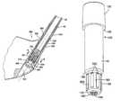
- FIG. 2is a cross-sectional view of a golf club head having a removable shaft, in accordance with one embodiment.
- FIG. 3is an exploded cross-sectional view of the shaft-club head connection assembly of FIG. 2 .
- FIG. 4is a cross-sectional view of the golf club head of FIG. 2 , taken along the line 4 - 4 of FIG. 2 .
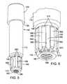
- FIG. 5is a perspective view of the shaft sleeve of the connection assembly shown in FIG. 2 .
- FIG. 6is an enlarged perspective view of the lower portion of the sleeve of FIG. 5 .
- FIG. 7is a cross-sectional view of the sleeve of FIG. 5 .
- FIG. 8is a top plan view of the sleeve of FIG. 5 .
- FIG. 9is a bottom plan view of the sleeve of FIG. 5 .
- FIG. 10is a cross-sectional view of the sleeve, taken along the line 10 - 10 of FIG. 7 .
- FIG. 11is a perspective view of the hosel insert of the connection assembly shown in FIG. 2 .
- FIG. 12is a cross-sectional view of the hosel insert of FIG. 2 .
- FIG. 13is a top plan view of the hosel insert of FIG. 11 .
- FIG. 14is a cross-sectional view of the hosel insert of FIG. 2 , taken along the line 14 - 14 of FIG. 12 .
- FIG. 15is a bottom plan view of the screw of the connection assembly shown in FIG. 2 .
- FIG. 16is a cross-sectional view similar to FIG. 2 identifying lengths used in calculating the stiffness of components of the shaft-head connection assembly.
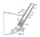
- FIG. 17is a cross-sectional view of a golf club head having a removable shaft, according to another embodiment.
- FIG. 18is an enlarged cross-sectional view of a golf club head having a removable shaft, in accordance with another embodiment.
- FIG. 19is an exploded cross-sectional view of the shaft-club head connection assembly of FIG. 18 .
- FIG. 20is an enlarged cross-sectional view of the golf club head of FIG. 18 , taken along the line 20 - 20 of FIG. 18 .
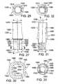
- FIG. 21is a perspective view of the shaft sleeve of the connection assembly shown in FIG. 18 .
- FIG. 22is an enlarged perspective view of the lower portion of the shaft sleeve of FIG. 21 .
- FIG. 23is a cross-sectional view of the shaft sleeve of FIG. 21 .
- FIG. 24is a top plan view of the shaft sleeve of FIG. 21 .
- FIG. 25is a bottom plan view of the shaft sleeve of FIG. 21 .
- FIG. 26is a cross-sectional view of the shaft sleeve, taken along line 26 - 26 of FIG. 23 .
- FIG. 27is a side elevational view of the hosel sleeve of the connection assembly shown in FIG. 18 .
- FIG. 28is a perspective view of the hosel sleeve of FIG. 27 .
- FIG. 29is a top plan view of the hosel sleeve of FIG. 27 , as viewed along longitudinal axis B defined by the outer surface of the lower portion of the hosel sleeve.
- FIG. 30is a cross-sectional view of the hosel sleeve, taken along line 30 - 30 of FIG. 27 .
- FIG. 31is a cross-sectional view of the hosel sleeve of FIG. 27 .
- FIG. 32is a top plan view of the hosel sleeve of FIG. 27 .
- FIG. 33is a bottom plan view of the hosel sleeve of FIG. 27 .
- FIG. 34is a cross-sectional view of the hosel insert of the connection usually shown in FIG. 18 .
- FIG. 35is a top plan view of the hosel insert of FIG. 34 .
- FIG. 36is a cross-sectional view of the hosel insert, taken along line 36 - 36 of FIG. 34 .
- FIG. 37is a bottom plan view of the hosel insert of FIG. 34 .
- FIG. 38is a cross-sectional view of the washer of the connection assembly shown in FIG. 18 .
- FIG. 39is a bottom plan view of the washer of FIG. 38 .
- FIG. 40is a cross-sectional view of the screw of FIG. 18 .
- FIG. 41is a cross-sectional view depicting the screw-washer interface of a connection assembly where the hosel sleeve longitudinal axis is aligned with the longitudinal axis of the hosel opening.
- FIG. 42is a cross-sectional view depicting a screw-washer interface of a connection assembly where the hosel sleeve longitudinal axis is offset from the longitudinal axis of the hosel opening.
- FIG. 43Ais an enlarged cross-sectional view of a golf club head having a removable shaft, in accordance with another embodiment.
- FIG. 43Bshows the golf club head of FIG. 43A with the screw loosened to permit removal of the shaft from the club head.
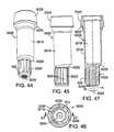
- FIG. 44is a perspective view of the shaft sleeve of the assembly shown in FIG. 43 .
- FIG. 45is a side elevation view of the shaft sleeve of FIG. 44 .
- FIG. 46is a bottom plan view of the shaft sleeve of FIG. 44 .
- FIG. 47is a cross-sectional view of the shaft sleeve taken along line 47 - 47 of FIG. 46 .
- FIG. 48is a cross-sectional view of another embodiment of a shaft sleeve.
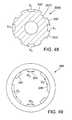
- FIG. 49is a top plan view of a hosel insert that is adapted to receive the shaft sleeve.
- FIG. 50is a cross-sectional view of another embodiment of a shaft sleeve.
- FIG. 51is a top plan view of a hosel insert that is adapted to receive the shaft sleeve.
- FIG. 52is a side elevational view of a golf club head having an adjustable sole plate, in accordance with one embodiment.
- FIG. 53is a bottom plan view of the golf club head of FIG. 48 .
- FIG. 54is a side elevation view of a golf club head having an adjustable sole portion, according to another embodiment.
- FIG. 55is a rear elevation view of the golf club head of FIG. 54 .
- FIG. 56is a bottom plan view of the golf club head of FIG. 54 .
- FIG. 57is a cross-sectional view of the golf club head taken along line 57 - 57 of FIG. 54 .
- FIG. 58is a cross-sectional view of the golf club head taken along line 58 - 58 of FIG. 56 .
- FIG. 59is a graph showing the effective face angle through a range of lie angles for a shaft positioned at a nominal position, a lofted position and a delofted position.
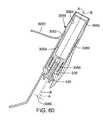
- FIG. 60is an enlarged cross-sectional view of a golf club head having a removable shaft, in accordance with another embodiment.
- FIGS. 61 and 62are front elevation and cross-sectional views, respectively, of the shaft sleeve of the assembly shown in FIG. 60 .
- the term “includes”means “comprises.”
- a device that includes or comprises A and Bcontains A and B but may optionally contain C or other components other than A and B.
- a device that includes or comprises A or Bmay contain A or B or A and B, and optionally one or more other components such as C.
- FIGS. 1A-1Dthere is shown characteristic angles of golf clubs by way of reference to a golf club head 300 having a removable shaft 50 , according to one embodiment.
- the club head 300comprises a centerface, or striking face, 310 , scorelines 320 , a hosel 330 having a hosel opening 340 , and a sole 350 .
- the hosel 330has a hosel longitudinal axis 60 and the shaft 50 has a shaft longitudinal axis.
- the ideal impact location 312 of the golf club head 300is disposed at the geometric center of the striking surface 310 (see FIG. 1A ).
- the ideal impact location 312is typically defined as the intersection of the midpoints of a height (H ss ) and width (W ss ) of the striking surface 310 .
- Both H ss and W ssare determined using the striking face curve (S ss ).
- the striking face curveis bounded on its periphery by all points where the face transitions from a substantially uniform bulge radius (face heel-to-toe radius of curvature) and a substantially uniform roll radius (face crown-to-sole radius of curvature) to the body (see e.g., FIG. 1 ).
- H ssis the distance from the periphery proximate the sole portion of S ss to the perhiphery proximate the crown portion of S ss measured in a vertical plane (perpendicular to ground) that extends through the geometric center of the face.
- W ssis the distance from the periphery proximate the heel portion of S ss to the periphery proximate the toe portion of S ss measured in a horizontal plane (e.g., substantially parallel to ground) that extends through the geometric center of the face. See USGA “Procedure for Measuring the Flexibility of a Golf Clubhead,” Revision 2.0 for the methodology to measure the geometric center of the striking face.
- a lie angle 10(also referred to as the “scoreline lie angle”) is defined as the angle between the hosel longitudinal axis 60 and a playing surface 70 when the club is in the grounded address position.
- the grounded address positionis defined as the resting position of the head on the playing surface when the shaft is supported at the grip (free to rotate about its axis) and the shaft is held at an angle to the ground such that the scorelines 320 are horizontal (if the club does not have scorelines, then the lie shall be set at 60-degrees).
- the centerface target line vectoris defined as a horizontal vector which is perpendicular to the shaft when the club is in the address position and points outward from the centerface point.
- the target line planeis defined as a vertical plane which contains the centerface target line vector.
- the square face address positionis defined as the head position when the sole is lifted off the ground, and the shaft is held (both positionally and rotationally) such that the scorelines are horizontal and the centerface normal vector completely lies in the target line plane (if the head has no scorelines, then the shaft shall be held at 60-degrees relative to ground and then the head rotated about the shaft axis until the centerface normal vector completely lies in the target line plane).
- the actual, or measured, lie anglecan be defined as the angle 10 between the hosel longitudinal axis 60 and the playing surface 70 , whether or not the club is held in the grounded address position with the scorelines horizontal.
- a loft angle 20 of the club head(referred to as “square loft”) is defined as the angle between the centerface normal vector and the ground plane when the head is in the square face address position.
- a hosel loft angle 72is defined as the angle between the hosel longitudinal axis 60 projected onto the target line plane and a plane 74 that is tangent to the center of the centerface.
- the shaft loft angleis the angle between plane 74 and the longitudinal axis of the shaft 50 projected onto the target line plane.
- the “grounded loft” 80 of the club headis the vertical angle of the centerface normal vector when the club is in the grounded address position (i.e., when the sole 350 is resting on the ground), or stated differently, the angle between the plane 74 of the centerface and a vertical plane when the club is in the grounded address position.
- a face angle 30is defined by the horizontal component of the centerface normal vector and a vertical plane (“target line plane”) that is normal to the vertical plane which contains the shaft longitudinal axis when the shaft 50 is in the correct lie (i.e., typically 60 degrees+/ ⁇ 5 degrees) and the sole 350 is resting on the playing surface 70 (the club is in the grounded address position).
- target line planea vertical plane that is normal to the vertical plane which contains the shaft longitudinal axis when the shaft 50 is in the correct lie (i.e., typically 60 degrees+/ ⁇ 5 degrees) and the sole 350 is resting on the playing surface 70 (the club is in the grounded address position).
- the lie angle 10 and/or the shaft loftcan be modified by adjusting the position of the shaft 50 relative to the club head.
- adjusting the position of the shafthas been accomplished by bending the shaft and the hosel relative to the club head.
- the lie angle 10can be increased by bending the shaft and the hosel inward toward the club head 300 , as depicted by shaft longitudinal axis 64 .
- the lie angle 10can be decreased by bending the shaft and the hosel outward from the club head 300 , as depicted by shaft longitudinal axis 62 .
- FIG. 1Cbending the shaft and the hosel forward toward the striking face 310 , as depicted by shaft longitudinal axis 66 , increases the shaft loft.
- shaft lofttypically is the same as the hosel loft because both the shaft and the hosel are bent relative to the club head.
- the position of the shaftcan be adjusted relative to the hosel to adjust shaft loft. In such cases, the shaft loft of the club is adjusted while the hosel loft is unchanged.
- Adjusting the shaft loftis effective to adjust the square loft of the club by the same amount.
- the face angle of the club headincreases or decreases in proportion to the change in shaft loft.
- shaft loftis adjusted to effect changes in square loft and face angle.
- the shaft and the hoselcan be bent to adjust the lie angle and the shaft loft (and therefore the square loft and the face angle) by bending the shaft and the hosel in a first direction inward or outward relative to the club head to adjust the lie angle and in a second direction forward or rearward relative to the club head to adjust the shaft loft.
- a golf clubcomprising a golf club head 300 attached to a golf club shaft 50 via a removable head-shaft connection assembly, which generally comprises in the illustrated embodiment a shaft sleeve 100 , a hosel insert 200 and a screw 400 .
- the club head 300is formed with a hosel opening, or passageway, 340 that extends from the hosel 330 through the club head and opens at the sole, or bottom surface, of the club head.
- the club head 300is removably attached to the shaft 50 by the sleeve 100 (which is mounted to the lower end portion of the shaft 50 ) by inserting the sleeve 100 into the hosel opening 340 and the hosel insert 200 (which is mounted inside the hosel opening 340 ), and inserting the screw 400 upwardly through the opening in the sole and tightening the screw into a threaded opening of the sleeve, thereby securing the club head 300 to the sleeve 100 .
- the club head 300comprises the head of a “wood-type” golf club. All of the embodiments disclosed in the present specification can be implemented in all types of golf clubs, including but not limited to, drivers, fairway woods, utility clubs, putters, wedges, etc.
- a shaft that is “removably attached” to a club headmeans that the shaft can be connected to the club head using one or more mechanical fasteners, such as a screw or threaded ferrule, without an adhesive, and the shaft can be disconnected and separated from the head by loosening or removing the one or more mechanical fasteners without the need to break an adhesive bond between two components.
- one or more mechanical fastenerssuch as a screw or threaded ferrule
- the sleeve 100is mounted to a lower, or tip end portion 90 of the shaft 50 .
- the sleeve 100can be adhesively bonded, welded or secured in equivalent fashion to the lower end portion of the shaft 50 .
- the sleeve 100may be integrally formed as part of the shaft 50 .
- a ferrule 52can be mounted to the end portion 90 of the shaft just above shaft sleeve 100 to provide a smooth transition between the shaft sleeve and the shaft and to conceal the glue line between the shaft and the sleeve. The ferrule also helps minimize tip breakage of the shaft.
- the hosel opening 340extends through the club head 300 and has hosel sidewalls 350 .
- a flange 360extends radially inward from the hosel sidewalls 350 and forms the bottom wall of the hosel opening.
- the flangedefines a passageway 370 , a flange upper surface 380 and a flange lower surface 390 .
- the hosel insert 200can be mounted within the hosel opening 340 with a bottom surface 250 of the insert contacting the flange upper surface 380 .
- the hosel insert 200can be adhesively bonded, welded, brazed or secured in another equivalent fashion to the hosel sidewalls 350 and/or the flange to secure the insert 200 in place.
- the hosel insert 200can be formed integrally with the club head 300 (e.g., the insert can be formed and/or machined directly in the hosel opening).
- the sleeve 100has a rotation prevention portion that mates with a complementary rotation prevention portion of the insert 200 .
- the shaft sleevehas a lower portion 150 having a non-circular configuration complementary to a non-circular configuration of the hosel insert 200 .
- the sleeve lower portion 150defines a keyed portion that is received by a keyway defined by the hosel insert 200 .
- the rotational prevention portion of the sleevecomprises longitudinally extending external splines 500 formed on an external surface 160 of the sleeve lower portion 150 , as illustrated in FIGS. 5-6 and the rotation prevention portion of the insert comprises complementary-configured internal splines 240 , formed on an inner surface 250 of the hosel insert 200 , as illustrated in FIGS. 11-14 .
- the rotation prevention portionscan be elliptical, rectangular, hexagonal or various other non-circular configurations of the sleeve external surface 160 and a complementary non-circular configuration of the hosel insert inner surface 250 .
- the screw 400comprises a head 410 having a surface 420 , and threads 430 .
- the screw 400is used to secure the club head 300 to the shaft 50 by inserting the screw through passageway 370 and tightening the screw into a threaded bottom opening 196 in the sleeve 100 .
- the club head 300can be secured to the shaft 50 by other mechanical fasteners.
- the head surface 420contacts the flange lower surface 390 and an annular thrust surface 130 of the sleeve 100 contacts a hosel upper surface 395 ( FIG. 2 ).
- the sleeve 100 , the hosel insert 200 , the sleeve lower opening 196 , the hosel opening 340 and the screw 400 in the illustrated exampleare co-axially aligned.
- connection assemblye.g., the sleeve 100 , the hosel insert 200 and the screw 400
- the various components of the connection assemblyare constructed from light-weight, high-strength metals and/or alloys (e.g., T6 temper aluminum alloy 7075, grade 5 6Al-4V titanium alloy, etc.) and designed with an eye towards conserving mass that can be used elsewhere in the golf club to enhance desirable golf club characteristics (e.g., increasing the size of the “sweet spot” of the club head or shifting the center of gravity to optimize launch conditions).
- the golf club having an interchangeable shaft and club head as described in the present applicationprovides a golfer with a club that can be easily modified to suit the particular needs or playing style of the golfer.
- a golfercan replace the club head 300 with another club head having desired characteristics (e.g., different loft angle, larger face area, etc.) by simply unscrewing the screw 400 from the sleeve 100 , replacing the club head and then screwing the screw 400 back into the sleeve 100 .
- the shaft 50similarly can be exchanged.
- the sleeve 100can be removed from the shaft 50 and mounted on the new shaft, or the new shaft can have another sleeve already mounted on or formed integral to the end of the shaft.
- any number of shaftsare provided with the same sleeve and any number of club heads is provided with the same hosel configuration and hosel insert 200 to receive any of the shafts.
- a pro shop or retailercan stock a variety of different shafts and club heads that are interchangeable.
- a club or a set of clubs that is customized to suit the needs of a consumercan be immediately assembled at the retail location.
- the sleeve 100 in the illustrated embodimentis substantially cylindrical and desirably is made from a light-weight, high-strength material (e.g., T6 temper aluminum alloy 7075).
- the sleeve 100includes a middle portion 110 , an upper portion 120 and a lower portion 150 .
- the upper portion 120can have a wider thickness than the remainder of the sleeve as shown to provide, for example, additional mechanical integrity to the connection between the shaft 50 and the sleeve 100 .
- the upper portion 120may have a flared or frustroconical shape, to provide, for example, a more streamlined transition between the shaft 50 and club head 300 .
- the boundary between the upper portion 120 and the middle portion 110comprises an upper annular thrust surface 130 and the boundary between the middle portion 110 and the lower portion 150 comprises a lower annular surface 140 .
- the annular surface 130is perpendicular to the external surface of the middle portion 110 .
- the annular surface 130may be frustroconical or otherwise taper from the upper portion 120 to the middle portion 110 .
- the annular surface 130bears against the hosel upper surface 395 when the shaft 50 is secured to the club head 300 .
- the sleeve 100further comprises an upper opening 192 for receiving the lower end portion 90 of the shaft 50 and an internally threaded opening 196 in the lower portion 150 for receiving the screw 400 .
- the upper opening 192has an annular surface 194 configured to contact a corresponding surface 70 of the shaft 50 ( FIG. 3 ).
- the upper opening 192can have a configuration adapted to mate with various shaft profiles (e.g., a constant inner diameter, plurality of stepped inner diameters, chamfered and/or perpendicular annular surfaces, etc.).
- splines 500are located below opening 192 (and therefore below the lower end of the shaft) to minimize the overall diameter of the sleeve.
- the threads in the lower opening 196can be formed using a Spiralock® tap.
- the rotation prevention portion of the sleeve 100 for restricting relative rotation between the shaft and the clubcomprises a plurality of external splines 500 formed on an external surface of the lower portion 150 and gaps, or keyways, between adjacent splines 500 .
- Each keywayhas an outer surface 160 .
- the sleevecomprises eight angularly spaced splines 500 elongated in a direction parallel to the longitudinal axis of the sleeve 100 . Referring to FIGS.
- each of the splines 500 in the illustrated configurationhas a pair of sidewalls 560 extending radially outwardly from the external surface 160 , beveled top and bottom edges 510 , bottom chamfered corners 520 and an arcuate outer surface 550 .
- the sidewalls 560desirably diverge or flair moving in a radially outward direction so that the width of the spline near the outer surface 550 is greater than the width at the base of the spline (near surface 160 ).
- the splines 500have a height H (the distance the sidewalls 550 extend radially from the external surface 160 ), and a width W 1 at the mid-span of the spline (the straight line distance extending between sidewalls 560 measured at locations of the sidewalls equidistant from the outer surface 550 and the surface 160 ).
- the sleevecomprises more or fewer splines and the splines 500 can have different shapes and sizes.
- Embodiments employing the spline configuration depicted in FIGS. 6-10provide several advantages. For example, a sleeve having fewer, larger splines provides for greater interference between the sleeve and the hosel insert, which enhances resistance to stripping, increases the load-bearing area between the sleeve and the hosel insert and provides for splines that are mechanically stronger. Further, complexity of manufacturing may be reduced by avoiding the need to machine smaller spline features. For example, various Rosch-manufacturing techniques (e.g., rotary, thru-broach or blind-broach) may not be suitable for manufacturing sleeves or hosel inserts having more, smaller splines.
- Rosch-manufacturing techniquese.g., rotary, thru-broach or blind-broach
- the splines 500have a spline height H of between about 0.15 mm to about 1.0 mm with a height H of about 0.5 mm being a specific example and a spline width W 1 of between about 0.979 mm to about 2.87 mm, with a width W 1 of about 1.367 mm being a specific example.
- the non-circular configuration of the sleeve lower portion 150can be adapted to limit the manner in which the sleeve 100 is positionable within the hosel insert 200 .
- the splines 500are substantially identical in shape and size. Six of the eight spaces between adjacent splines can have a spline-to-spline spacing S 1 and two diametrically-opposed spaces can have a spline-to-spline spacing S 2 , where S 2 is a different than S 1 (S 2 is greater than S 1 in the illustrated embodiment).
- the arc angle of S 1is about 21 degrees and the arc angle of S 2 is about 33 degrees.
- This spline configurationallows the sleeve 100 to be dually positionable within the hosel insert 200 (i.e., the sleeve 100 can be inserted in the insert 200 at two positions, spaced 180 degrees from each other, relative to the insert).
- the splinescan be equally spaced from each other around the longitudinal axis of the sleeve.
- different non-circular configurations of the lower portion 150e.g., triangular, hexagonal, more of fewer splines
- the sleeve lower portion 150can have a generally rougher outer surface relative to the remaining surfaces of the sleeve 100 in order to provide, for example, greater friction between the sleeve 100 and the hosel insert 200 to further restrict rotational movement between the shaft 50 and the club head 300 .
- the external surface 160can be roughened by sandblasting, although alternative methods or techniques can be used.
- the general configuration of the sleeve 100can vary from the configuration illustrated in FIGS. 5-10 .
- the relative lengths of the upper portion 120 , the middle portion 110 and the lower portion 150can vary (e.g., the lower portion 150 could comprise a greater or lesser proportion of the overall sleeve length).
- additional sleeve surfacescould contact corresponding surfaces in the hosel insert 200 or hosel opening 340 when the club head 300 is attached to the shaft 50 .
- annular surface 140 of the sleevemay contact upper spline surfaces 230 of the hosel insert 200
- annular surface 170 of the sleevemay contact a corresponding surface on an inner surface of the hosel insert 200
- a bottom face 180 of the sleevemay contact the flange upper surface 360
- the lower opening 196 of the sleevecan be in communication with the upper opening 192 , defining a continuous sleeve opening and reducing the weight of the sleeve 100 by removing the mass of material separating openings 196 and 192 .
- the hosel insert 200desirably is substantially tubular or cylindrical and can be made from a light-weight, high-strength material (e.g., grade 5 6Al-4V titanium alloy).
- the hosel insert 200comprises an inner surface 250 having a non-circular configuration complementary to the non-circular configuration of the external surface of the sleeve lower portion 150 .
- the non-circulation configurationcomprises splines 240 complementary in shape and size to the splines 500 of the sleeve 150 .
- splines 240elongated in a direction parallel to the longitudinal axis of the hosel insert 200 and the splines 240 have sidewalls 260 extending radially inward from the inner surface 250 , chamfered top edges 230 and an inner surface 270 .
- the sidewalls 260desirably taper or converge toward each other moving in a radially inward direction to mate with the flared splines 500 of the sleeve.
- the radially inward sidewalls 260have at least one advantage in that full surface contact occurs between the teeth and the mating teeth of the sleeve insert.
- At least one advantageis that the translational movement is more constrained within the assembly compared to other spline geometries having the same tolerance. Furthermore, the radially inward sidewalls 260 promote full sidewall engagement rather than localized contact resulting in higher stresses and lower durability.
- the spline configuration of the hosel insertis complementary to the spline configuration of the sleeve lower portion 150 and as such, adjacent pairs of splines 240 have a spline-to-spline spacing S 3 that is slightly greater than the width of the sleeve splines 500 .
- Six of the splines 240have a width W 2 slightly less than inter-spline spacing S 1 of the sleeve splines 500 and two diametrically-opposed splines have a width W 3 slightly less than inter-spline spacing S 2 of the sleeve splines 500 , wherein W 2 is less than W 3 .
- the hosel insert inner surfacecan have various non-circular configurations complementary to the non-circular configuration of the sleeve lower portion 160 .
- Selected surfaces of the hosel insert 200can be roughened in a similar manner to the exterior surface 160 of the shaft.
- the entire surface area of the insertcan be provided with a roughened surface texture.
- only the inner surface 240 of the hosel insert 200can be roughened.
- the screw 400desirably is made from a light-weight, high-strength material (e.g., T6 temper aluminum alloy 7075).
- the major diameter (i.e., outer diameter) of the threads 430is less than 6 mm (e.g., ISO screws smaller than M6) and is either about 4 mm or 5 mm (e.g., M4 or M5 screws).
- reducing the thread diameterincreases the ability of the screw to elongate or stretch when placed under a load, resulting in a greater preload for a given torque.
- the use of relatively smaller diameter screwsallows a user to secure the club head to the shaft with less effort and allows the golfer to use the club for longer periods of time before having to retighten the screw.
- the head 410 of the screwcan be configured to be compatible with a torque wrench or other torque-limiting mechanism.
- the screw headcomprises a “hexalobular” internal driving feature (e.g., a TORX screw drive) (such as shown in FIG. 15 ) to facilitate application of a consistent torque to the screw and to resist cam-out of screwdrivers.
- Securing the club head 300 to the shaft 50 with a torque wrenchcan ensure that the screw 400 is placed under a substantially similar preload each time the club is assembled, ensuring that the club has substantially consistent playing characteristics each time the club is assembled.
- the screw head 410can comprise various other drive designs (e.g., Phillips, Pozidriv, hexagonal, TTAP, etc.), and the user can use a conventional screwdriver rather than a torque wrench to tighten the screw.
- the club head-shaft connectiondesirably has a low axial stiffness.
- the axial stiffness, k, of an elementis defined as
- Ethe Young's modulus of the material of the element
- Athe cross-sectional area of the element
- Lthe length of the element.
- L screwis the length of the portion of the screw placed in tension (measured from the flange bottom 390 to the bottom end of the shaft sleeve).
- L shaftis the length of the portion of the shaft 50 extending into the hosel opening 340 (measured from hosel upper surface 395 to the end of the shaft); and L sleeve is the length of the sleeve 100 placed in tension (measured from hosel upper surface 395 to the end of the sleeve), as depicted in FIG. 16 .
- k screw , k shaft and k sleevecan be determined using the lengths in Equation 1.
- Table 1shows calculated k values for certain components and combinations thereof for the connection assembly of FIGS. 2-14 and those of other commercially available connection assemblies used with removably attachable golf club heads.
- the effective hosel stiffness, K hoselis also shown for comparison purposes (calculated over the portion of the hosel that is in compression during screw preload).
- a low k eff /k hosel ratioindicates a small shaft connection assembly stiffness compared to the hosel stiffness, which is desirable in order to help maintain preload for a given screw torque during dynamic loading of the head.
- the k eff of the sleeve-shaft-screw combination of the connection assembly of illustrated embodimentis 9.27 ⁇ 10 7 N/m, which is the lowest among the compared connection assemblies.
- connection assemblycan be modified to achieve different values.
- the screw 400can be longer than shown in FIG. 16 .
- the length of the opening 196can be increased along with a corresponding increase in the length of the screw 400 .
- the construction of the hosel opening 340can vary to accommodate a longer screw.
- a club head 600comprises an upper flange 610 defining the bottom wall of the hosel opening and a lower flange 620 spaced from the upper flange 610 to accommodate a longer screw 630 .
- Such a hosel constructioncan accommodate a longer screw, and thus can achieve a lower k eff , while retaining compatibility with the sleeve 100 of FIGS. 5-10 .
- the cross-sectional area of the sleeve 100is minimized to minimize k sleeve , by placing the splines 500 below the shaft, rather than around the shaft as used in prior art configurations.
- a shaft sleevecan have 4, 6, 8, 10, or 12 splines.
- the height H of the splines of the shaft sleeve in particular embodimentscan range from about 0.15 mm to about 0.95 mm, and more particularly from about 0.25 mm to about 0.75 mm, and even more particularly from about 0.5 mm to about 0.75 mm.
- the average diameter D of the spline portion of the shaft sleevecan range from about 6 mm to about 12 mm, with 8.45 mm being a specific example. As shown in FIG. 10 , the average diameter is the diameter of the spline portion of a shaft sleeve measured between two points located at the mid-spans of two diametrically opposed splines.
- the length L of the splines of the shaft sleeve in particular embodimentscan range from about 2 mm to about 10 mm.
- the splinescan be relatively longer, for example, 7.5 mm or 10 mm.
- the connection assemblyis implemented in a fairway wood, which is typically smaller than a driver, it is desirable to use a relatively shorter shaft sleeve because less space is available inside the club head to receive the shaft sleeve.
- the splinescan be relatively shorter, for example, 2 mm or 3 mm in length, to reduce the overall length of the shaft sleeve.
- the ratio of spline width W 1 (at the midspan of the spline) to average diameter of the spline portion of the shaft sleeve in particular embodimentscan range from about 0.1 to about 0.5, and more desirably, from about 0.15 to about 0.35, and even more desirably from about 0.16 to about 0.22.
- the ratio of spline width W 1 to spline H in particular embodimentscan range from about 1.0 to about 22, and more desirably from about 2 to about 4, and even more desirably from about 2.3 to about 3.1.
- the ratio of spline length L to average diameter in particular embodimentscan range from about 0.15 to about 1.7.
- Tables 2-4 belowprovide dimensions for a plurality of different spline configurations for the sleeve 100 (and other shaft sleeves disclosed herein).
- the average radius Ris the radius of the spline portion of a shaft sleeve measured at the mid-span of a spine, i.e., at a location equidistant from the base of the spline at surface 160 and to the outer surface 550 of the spline (see FIG. 10 ).
- the arc length in Tables 2 and 3is the arc length of a spline at the average radius.
- Table 2shows the spline arc angle, average radius, average diameter, arc length, arc length, arc length/average radius ratio, width at midspan, width (at midspan)/average diameter ratio for different shaft sleeves having 8 splines (with two 33 degree gaps as shown in FIG. 10 ), 8 equally-spaced splines, 6 equally-spaced splines, 10 equally-spaced splines, 4 equally-spaced splines.
- Table 3shows examples of shaft sleeves having different number of splines and spline heights.
- Table 4shows examples of different combinations of lengths and average diameters for shaft sleeves apart from the number of splines, spline height H, and spline width W 1 .
- a golf clubcomprising a head 700 attached to a removable shaft 800 via a removable head-shaft connection assembly.
- the connection assemblygenerally comprises a shaft sleeve 900 , a hosel sleeve 1000 (also referred to herein as an adapter sleeve), a hosel insert 1100 , a washer 1200 and a screw 1300 .
- the club head 700comprises a hosel 702 defining a hosel opening, or passageway 710 .
- the passageway 710 in the illustrated embodimentextends through the club head and forms an opening in the sole of the club head to accept the screw 1300 .
- the club head 700is removably attached to the shaft 800 by the shaft sleeve 900 (which is mounted to the lower end portion of the shaft 800 ) being inserted into and engaging the hosel sleeve 1000 .
- the hosel sleeve 1000is inserted into and engages the hosel insert 1100 (which is mounted inside the hosel opening 710 ).
- the screw 1300is tightened into a threaded opening of the shaft sleeve 900 , with the washer 1200 being disposed between the screw 1300 and the hosel insert 1100 , to secure the shaft to the club head.
- the shaft sleeve 900can be adhesively bonded, welded or secured in equivalent fashion to the lower end portion of the shaft 800 . In other embodiments, the shaft sleeve 900 may be integrally formed with the shaft 800 .
- the hosel opening 710extends through the club head 700 and has hosel sidewalls 740 defining a first hosel inner surface 750 and a second hosel inner surface 760 , the boundary between the first and second hosel inner surfaces defining an inner annular surface 720 .
- the hosel sleeve 1000is disposed between the shaft sleeve 900 and the hosel insert 1100 .
- the hosel insert 1100can be mounted within the hosel opening 710 .
- the hosel insert 1100can have an annular surface 1110 that contacts the hosel annular surface 720 .
- the hosel insert 1100can be adhesively bonded, welded or secured in equivalent fashion to the first hosel surface 740 , the second hosel surface 750 and/or the hosel annular surface 720 to secure the hosel insert 1100 in place.
- the hosel insert 1100can be formed integrally with the club head 700 .
- Rotational movement of the shaft 800 relative to the club head 700can be restricted by restricting rotational movement of the shaft sleeve 900 relative to the hosel sleeve 1000 and by restricting rotational movement of the hosel sleeve 1000 relative to the club head 700 .
- the shaft sleevehas a lower, rotation prevention portion 950 having a non-circular configuration that mates with a complementary, non-circular configuration of a lower, rotation prevention portion 1096 inside the hosel sleeve 1000 .
- the rotation prevention portion of the shaft sleeve 900can comprise longitudinally extending splines 1400 formed on an external surface 960 of the lower portion 950 , as best shown in FIGS. 21-22 .
- the rotation prevention portion of the hosel sleevecan comprise complementary-configured splines 1600 formed on an inner surface 1650 of the lower portion 1096 of the hosel sleeve, as best shown in FIGS. 30-31 .
- the hosel sleeve 1000can have a lower, rotation prevention portion 1050 having a non-circular configuration that mates with a complementary, non-circular configuration of a rotation prevention portion of the hosel insert 1100 .
- the rotation prevention portion of the hosel sleevecan comprise longitudinally extending splines 1500 formed on an external surface 1090 of a lower portion 1050 of the hosel sleeve 1000 , as best shown in FIGS. 27-28 and 29 .
- the rotation prevention portion of the hosel insertcan comprise of complementary-configured splines 1700 formed on an inner surface 1140 of the hosel insert 1100 , as best shown in FIGS. 34 and 36 .
- the shaft sleeve lower portion 950defines a keyed portion that is received by a keyway defined by the hosel sleeve inner surface 1096
- hosel sleeve outer surface 1050defines a keyed portion that is received by a keyway defined by the hosel insert inner surface 1140
- the rotation prevention portionscan be elliptical, rectangular, hexagonal or other non-circular complementary configurations of the shaft sleeve lower portion 950 and the hosel sleeve inner surface 1096 , and the hosel sleeve outer surface 1050 and the hosel insert inner surface 1140 .
- the screw 1300comprises a head 1330 having head, or bearing, surface 1320 , a shaft 1340 extending from the head and external threads 1310 formed on a distal end portion of the screw shaft.
- the screw 1300is used to secure the club head 700 to the shaft 800 by inserting the screw upwardly into passageway 710 via an opening in the sole of the club head.
- the screwis further inserted through the washer 1200 and tightened into an internally threaded bottom portion 996 of an opening 994 in the sleeve 900 .
- the club head 700can be secured to the shaft 800 by other mechanical fasteners.
- the hosel sleeve 1000is configured to support the shaft 50 at a desired orientation relative to the club head to achieve a desired shaft loft and/or lie angle for the club.
- the hosel sleeve 1000comprises an upper portion 1020 , a lower portion 1050 , and a bore or longitudinal opening 1040 extending therethrough.
- the upper portionwhich extends parallel the opening 1040 , extends at an angle with respect to the lower portion 1050 defined as an “offset angle” 780 ( FIG. 18 ).
- offset angle780
- the outer surface of the lower portion 1050is co-axially aligned with the hosel insert 1100 and the hosel opening.
- the outer surface of the lower portion 1050 of the hosel sleeve, the hosel insert 1100 , and the hosel opening 710collectively define a longitudinal axis B.
- the shaft sleeve, the shaft, and the opening 1040collectively define a longitudinal axis A of the assembly.
- the hosel sleeveis effective to support the shaft 50 along longitudinal axis A, which is offset from longitudinal axis B by offset angle 780 .
- the hosel sleeve 1000can be positioned in the hosel insert 1100 in one or more positions to adjust the shaft loft and/or lie angle of the club.
- FIG. 20represents a connection assembly embodiment wherein the hosel sleeve can be positioned in four angularly spaced, discrete positions within the hosel insert 1100 .
- a sleeve having a plurality of “discrete positions”means that once the sleeve is inserted into the club head, it cannot be rotated about its longitudinal axis to an adjacent position, except for any play or tolerances between mating splines that allows for slight rotational movement of the sleeve prior to tightening the screw or other fastening mechanism that secures the shaft to the club head.
- crosshairs A 1 -A 4represent the position of the longitudinal axis A for each position of the hosel sleeve 1000 .
- Positioning the hosel sleeve within the club head such that the shaft is adjusted inward towards the club head (such that the longitudinal axis A passes through crosshair A 4 in FIG. 20 )increases the lie angle from an initial lie angle defined by longitudinal axis B; positioning the hosel sleeve such that the shaft is adjusted away from the club head (such that axis A passes through crosshair A 3 ) reduces the lie angle from an initial lie angle defined by longitudinal axis B.
- hosel sleevepositioning the hosel sleeve such that the shaft is adjusted forward toward the striking face (such that axis A passes through crosshair A 2 ) or rearward toward the rear of the club head (such that axis A passes through the crosshair A 1 ) will increase or decrease the shaft loft, respectively, from an initial shaft loft angle defined by longitudinal axis B.
- adjusting the shaft loftis effective to adjust the square loft by the same amount.
- the face angleis adjusted in proportion to the change in shaft loft.
- the amount of increase or decrease in shaft loft or lie angle in this exampleis equal to the offset angle 780 .
- the shaft sleeve 900can be inserted into the hosel sleeve at various angularly spaced positions around longitudinal axis A. Consequently, if the orientation of the shaft relative to the club head is adjusted by rotating the position of the hosel sleeve 1000 , the position of the shaft sleeve within the hosel sleeve can be adjusted to maintain the rotational position of the shaft relative to longitudinal axis A. For example, if the hosel sleeve is rotated 90 degrees with respect to the hosel insert, the shaft sleeve can be rotated 90 degrees in the opposite direction with respect to the hosel sleeve in order to maintain the position of the shaft relative to its longitudinal axis. In this manner, the grip of the shaft and any visual indicia on the shaft can be maintained at the same position relative to the shaft axis as the shaft loft and/or lie angle is adjusted.
- a connection assemblycan employ a hosel sleeve that is positionable at eight angularly spaced positions within the hosel insert 1100 , as represented by cross hairs A 1 -A 8 in FIG. 20 .
- Crosshairs A 5 -A 8represent hosel sleeve positions within the hosel insert 1100 that are effective to adjust both the lie angle and the shaft loft (and therefore the square loft and the face angle) relative to an initial lie angle and shaft loft defined by longitudinal axis B by adjusting the orientation of the shaft in a first direction inward or outward relative to the club head to adjust the lie angle and in a second direction forward or rearward relative to the club head to adjust the shaft loft.
- crosshair A 5represents a hosel sleeve position that adjusts the orientation of the shaft outward and rearward relative to the club head, thereby decreasing the lie angle and decreasing the shaft loft.
- connection assembly embodiment illustrated in FIGS. 18-20provides advantages in addition to those provided by the illustrated embodiment of FIGS. 2-4 (e.g., ease of exchanging a shaft or club head) and already described above. Because the hosel sleeve can introduce a non-zero angle between the shaft and the hosel, a golfer can easily change the loft, lie and/or face angles of the club by changing the hosel sleeve.
- the golfercan unscrew the screw 1300 from the shaft sleeve 900 , remove the shaft 800 from the hosel sleeve 1000 , remove the hosel sleeve 1000 from the hosel insert 1100 , select another hosel sleeve having a desired offset angle, insert the shaft sleeve 900 into the replacement hosel sleeve, insert the replacement hosel sleeve into the hosel insert 1000 , and tighten the screw 1300 into the shaft sleeve 900 .
- a hosel sleeve in the shaft-head connection assemblyallows the golfer to adjust the position of the shaft relative to the club head without having to resort to such traditional methods such as bending the shaft relative to the club head as described above.
- a golf club utilizing the club head-shaft connection assembly of FIGS. 18-20comprising a first hosel sleeve wherein the shaft axis is co-axially aligned with the hosel axis (i.e., the offset angle is zero, or, axis A passes through crosshair B).
- the replacement hosel sleevescould be purchased individually from a retailer.
- a kitcomprising a plurality of hosel sleeves, each having a different offset angle can be provided.
- the number of hosel sleeves in the kitcan vary depending on a desired range of offset angles and/or a desired granularity of angle adjustments.
- a kitcan comprise hosel sleeves providing offset angles from 0 degrees to 3 degrees, in 0.5 degree increments.
- hosel sleeve kitsthat are compatible with any number of shafts and any number of club heads having the same hosel configuration and hosel insert 1100 are provided.
- a pro shop or retailerneed not necessarily stock a large number of shaft or club head variations with various loft, lie and/or face angles. Rather, any number of variations of club characteristic angles can be achieved by a variety of hosel sleeves, which can take up less retail shelf and storeroom space and provide the consumer with a more economic alternative to adjusting loft, lie or face angles (i.e., the golfer can adjust a loft angle by purchasing a hosel sleeve instead of a new club).
- the shaft sleeve 900 in the illustrated embodimentis substantially cylindrical and desirably is made from a light-weight, high-strength material (e.g., T6 temper aluminum alloy 7075).
- the shaft sleeve 900can include a middle portion 910 , an upper portion 920 and a lower portion 950 .
- the upper portion 920can have a greater thickness than the remainder of the shaft sleeve to provide, for example, additional mechanical integrity to the connection between the shaft 800 and the shaft sleeve 900 .
- the upper portion 920can have a flared or frustroconical shape as shown, to provide, for example, a more streamlined transition between the shaft 800 and club head 700 .
- the boundary between the upper portion 920 and the middle portion 910defines an upper annular thrust surface 930 and the boundary between the middle portion 910 and the lower portion 950 defines a lower annular surface 940 .
- the shaft sleeve 900has a bottom surface 980 .
- the annular surface 930is perpendicular to the external surface of the middle portion 910 .
- the annular surface 930may be frustroconical or otherwise taper from the upper portion 920 to the middle portion 910 .
- the annular surface 930bears against the upper surface 1010 of the hosel insert 1000 when the shaft 800 is secured to the club head 700 ( FIG. 18 ).
- the shaft sleeve 900further comprises an opening 994 extending the length of the shaft sleeve 900 , as depicted in FIG. 23 .
- the opening 994has an upper portion 998 for receiving the shaft 800 and an internally threaded bottom portion 996 for receiving the screw 1300 .
- the opening upper portion 998has an internal sidewall having a constant diameter that is complementary to the configuration of the lower end portion of the shaft 800 .
- the opening upper portion 998can have a configuration adapted to mate with various shaft profiles (e.g., the opening upper portion 998 can have more than one inner diameter, chamfered and/or perpendicular annular surfaces, etc.).
- splines 1400are located below the opening upper portion 998 and therefore below the shaft to minimize the overall diameter of the shaft sleeve.
- the internal threads of the lower opening 996are created using a Spiralock® tap.
- the rotation prevention portion of the shaft sleevecomprises a plurality of splines 1400 on an external surface 960 of the lower portion 950 that are elongated in the direction of the longitudinal axis of the shaft sleeve 900 , as shown in FIGS. 21-22 and 26 .
- the splines 1400have sidewalls 1420 extending radially outwardly from the external surface 960 , bottom edges 1410 , bottom corners 1422 and arcuate outer surfaces 1450 .
- the external surface 960can comprise more splines (such as up to 12) or fewer than four splines and the splines 1400 can have different shapes and sizes.
- the hosel sleeve 1000 in the illustrated embodimentis substantially cylindrical and desirably is made from a light-weight, high-strength material (e.g., T6 temper aluminum alloy 7075).
- the hosel sleeve 1000includes an upper portion 1020 and a lower portion 1050 .
- the upper portion 1020can have a flared or frustroconical shape, with the boundary between the upper portion 1020 and the lower portion 1050 defining an annular thrust surface 1060 .
- the annular surface 1060tapers from the upper portion 1020 to the lower portion 1050 .
- the annular surface 1060can be perpendicular to the external surface 1090 of the lower portion 1050 .
- the annular surface 1060bears against the upper annular surface 730 of the hosel when the shaft 800 is secured to the club head 700 .
- the hosel sleeve 1000further comprises an opening 1040 extending the length of the hosel sleeve 1000 .
- the hosel sleeve opening 1040has an upper portion 1094 with internal sidewalls 1095 that are complementary configured to the configuration of the shaft sleeve middle portion 910 , and a lower portion 1096 defining a rotation prevention portion having a non-circular configuration complementary to the configuration of shaft sleeve lower portion 950 .
- the non-circular configuration of the hosel sleeve lower portion 1096comprises a plurality of splines 1600 formed on an inner surface 1650 of the opening lower portion 1096 .
- the inner surface 1650comprises four splines 1600 elongated in the direction of the longitudinal axis (axis A) of the hosel sleeve opening.
- the splines 1600 in the illustrated embodimenthave sidewalls 1620 extending radially inwardly from the inner surface 1650 and arcuate inner surfaces 1630 .
- the external surface of the lower portion 1050defines a rotation prevention portion comprising four splines 1500 elongated in the direction of and are parallel to longitudinal axis B defined by the external surface of the lower portion, as depicted in FIGS. 27 and 31 .
- the splines 1500have sidewalls 1520 extending radially outwardly from the surface 1550 , top and bottom edges 1540 and accurate outer surfaces 1530 .
- the splined configuration of the shaft sleeve 900dictates the degree to which the shaft sleeve 900 is positionable within the hosel sleeve 1000 .
- the splines 1400 and 1600are substantially identical in shape and size and adjacent pairs of splines 1400 and 1600 have substantially similar spline-to-spline spacings.
- This spline configurationallows the shaft sleeve 900 to be positioned within the hosel sleeve 1000 at four angularly spaced positions relative to the hosel sleeve 1000 .
- the hosel sleeve 1000can be positioned within the club head 700 at four angularly spaced positions.
- different non-circular configurationse.g., triangular, hexagonal, more or fewer splines, variable spline-to-spline spacings or spline widths
- the shaft sleeve lower portion 950 , the hosel opening lower portion 1096 , the hosel lower portion 1050 and the hosel insert inner surface 1140could provide for various degrees of positionability.
- the external surface of the shaft sleeve lower portion 950 , the internal surface of the hosel sleeve opening lower portion 1096 , the external surface of the hosel sleeve lower portion 1050 , and the internal surface of the hosel insertcan have generally rougher surfaces relative to the remaining surfaces of the shaft sleeve 900 , the hosel sleeve 1000 and the hosel insert.
- the enhanced surface roughnessprovides, for example, greater friction between the shaft sleeve 900 and the hosel sleeve 1000 and between the hosel sleeve 1000 and the hosel insert 1100 to further restrict relative rotational movement between these components.
- the contacting surfaces of shaft sleeve, the hosel sleeve and the hosel insertcan be roughened by sandblasting, although alternative methods or techniques can be used.
- the hosel insert 1100desirably is substantially tubular or cylindrical and can be made from a light-weight, high-strength material (e.g., grade 5 6Al-4V titanium alloy).
- the hosel insert 1100comprises an inner surface 1140 defining a rotation prevention portion having a non-circular configuration that is complementary to the non-circular configuration of the hosel sleeve outer surface 1090 .
- the non-circulation configuration of inner surface 1140comprises internal splines 1700 that are complementary in shape and size to the external splines 1500 of the hosel sleeve 1000 .
- the hosel insert 1100can comprises an annular surface 1110 that contacts hosel annual surface 720 when the insert 1100 is mounted in the hosel opening 710 as depicted in FIG. 18 . Additionally, the hosel opening 710 can have an annular shoulder (similar to shoulder 360 in FIG. 3 ). The insert 1100 can be welded or otherwise secured to the shoulder.
- the screw 1300desirably is made from a lightweight, high-strength material (e.g., T6 temper aluminum alloy 7075).
- the major diameter (i.e., outer diameter) of the threads 1310is about 4 mm (e.g., ISO screw size) but may be smaller or larger in alternative embodiments.
- the benefits of using a screw 1300 having a reduced thread diameter (about 4 mm or less)include the benefits described above with respect to screw 400 (e.g., the ability to place the screw under a greater preload for a given torque).
- the head 1330 of the screw 1300can be similar to the head 410 of the screw 400 ( FIG. 15 ) and can comprise a hexalobular internal driving feature as described above.
- the screw head 1330can comprise various other drive designs (e.g., Phillips, Pozidriv, hexagonal, TTAP, etc.), and the user can use a conventional screwdriver to tighten the screw.
- the screw 1300desirably has an inclined, spherical bottom surface 1320 .
- the washer 1200desirably comprises a tapered bottom surface 1220 , an upper surface 1210 , an inner surface 1240 and an inner circumferential edge 1225 defined by the boundary between the tapered surface 1220 and the inner surface 1240 .
- a hosel sleeve 1000can be selected to support the shaft at a non-zero angle with respect to the longitudinal axis of the hosel opening.
- the shaft sleeve 900 and the screw 1300extend at a non-zero angle with respect to the longitudinal axis of the hosel insert 1100 and the washer 1200 . Because of the inclined surfaces 1320 and 1220 of the screw and the washer, the screw head can make complete contact with the washer through 360 degrees to better secure the shaft sleeve in the hosel insert. In certain embodiments, the screw head can make complete contact with the washer regardless of the position of the screw relative to the longitudinal axis of the hosel opening.
- the head-shaft connection assemblyemploys a first hosel sleeve having a longitudinal axis that is co-axially aligned with the hosel sleeve opening longitudinal axis (i.e., the offset angle between the two longitudinal axes A and B is zero).
- the screw 1300contacts the washer 1200 along the entire circumferential edge 1225 of the washer 1200 .
- the tapered washer surface 1220 and the tapered screw head surface 1320allow for the screw 1300 to maintain contact with the entire circumferential edge 1225 of the washer 1200 .
- Such a washer-screw connectionallows the bolt to be loaded in pure axial tension without being subjected to any bending moments for a greater preload at a given installation torque, resulting in the club head 700 being more reliably and securely attached to the shaft 800 . Additionally, this configuration allows for the compressive force of the screw head to be more evenly distributed across the washer upper surface 1210 and hosel insert bottom surface 1120 interface.
- FIG. 43Ashows another embodiment of a gold club assembly that has a removable shaft that can be supported at various positions relative to the head to vary the shaft loft and/or the lie angle of the club.
- the assemblycomprises a club head 3000 having a hosel 3002 defining a hosel opening 3004 .
- the hosel opening 3004is dimensioned to receive a shaft sleeve 3006 , which in turn is secured to the lower end portion of a shaft 3008 .
- the shaft sleeve 3006can be adhesively bonded, welded or secured in equivalent fashion to the lower end portion of the shaft 3008 .
- the shaft sleeve 3006can be integrally formed with the shaft 3008 .
- a ferrule 3010can be disposed on the shaft just above the shaft sleeve 3006 to provide a transition piece between the shaft sleeve and the outer surface of the shaft 3008 .
- the hosel opening 3004is also adapted to receive a hosel insert 200 (described in detail above), which can be positioned on an annular shoulder 3012 inside the club head.
- the hosel insert 200can be secured in place by welding, an adhesive, or other suitable techniques.
- the insertcan be integrally formed in the hosel opening.
- the club head 3000further includes an opening 3014 in the bottom or sole of the club head that is sized to receive a screw 400 .
- the screw 400is inserted into the opening 3014 , through the opening in shoulder 3012 , and is tightened into the shaft sleeve 3006 to secure the shaft to the club head.
- the shaft sleeve 3006is configured to support the shaft at different positions relative to the club head to achieve a desired shaft loft and/or lie angle.
- a screw capturing devicesuch as in the form of an o-ring or washer 3036 , can be placed on the shaft of the screw 400 above shoulder 3012 to retain the screw in place within the club head when the screw is loosened to permit removal of the shaft from the club head.
- the ring 3036desirably is dimensioned to frictionally engage the threads of the screw and has a outer diameter that is greater than the central opening in shoulder 3012 so that the ring 3036 cannot fall through the opening.
- the ring 3036captures the distal end of the screw to retain the screw within the club head to prevent loss of the screw.
- the ring 3036desirably comprises a polymeric or elastomeric material, such as rubber, Viton, Neoprene, silicone, or similar materials.
- the ring 3036can be an o-ring having a circular cross-sectional shape as depicted in the illustrated embodiment.
- the ring 3036can be a flat washer having a square or rectangular cross-sectional shape.
- the ring 3036can various other cross-sectional profiles.
- the shaft sleeve 3006is shown in greater detail in FIGS. 44-47 .
- the shaft sleeve 3006 in the illustrated embodimentcomprises an upper portion 3016 having an upper opening 3018 for receiving and a lower portion 3020 located below the lower end of the shaft.
- the lower portion 3020can have a threaded opening 3034 for receiving the threaded shaft of the screw 400 .
- the lower portion 3020 of the sleevecan comprise a rotation prevention portion configured to mate with a rotation prevention portion of the hosel insert 200 to restrict relative rotation between the shaft and the club head.
- the rotation prevention portioncan comprise a plurality of longitudinally extending external splines 500 that are adapted to mate with corresponding internal splines 240 of the hosel insert 200 ( FIGS. 11-14 ).
- the lower portion 3020 and the external splines 500 formed thereoncan have the same configuration as the shaft lower portion 150 and splines 500 shown in FIGS. 5-7 and 9 - 10 and described in detail above. Thus, the details of splines 500 are not repeated here.
- the upper portion 3016 of the sleeveextends at an offset angle 3022 relative to the lower portion 3020 .
- the lower portion 3020when inserted in the club head, the lower portion 3020 is co-axially aligned with the hosel insert 200 and the hosel opening 3004 , which collectively define a longitudinal axis B.
- the upper portion 3016 of the shaft sleeve 3006defines a longitudinal axis A and is effective to support the shaft 3008 along axis A, which is offset from longitudinal axis B by offset angle 3022 . Inserting the shaft sleeve at different angular positions relative to the hosel insert is effective to adjust the shaft loft and/or the lie angle, as further described below.
- the upper portion 3016 of the shaft sleevedesirably has a constant wall thickness from the lower end of opening 3018 to the upper end of the shaft sleeve.
- a tapered surface portion 3026extends between the upper portion 3016 and the lower portion 3020 .
- the upper portion 3016 of the shaft sleevehas an enlarged head portion 3028 that defines an annular bearing surface 3030 that contacts an upper surface 3032 of the hosel 3002 ( FIG. 43 ).
- the bearing surface 3030desirably is oriented at a 90-degree angle with respect to longitudinal axis B so that when the shaft sleeve is inserted in to the hosel, the bearing surface 3030 can make complete contact with the opposing surface 3032 of the hosel through 360 degrees.
- the hosel opening 3004desirably is dimensioned to form a gap 3024 between the outer surface of the upper portion 3016 of the sleeve and the opposing internal surface of the club head. Because the upper portion 3016 is not co-axially aligned with the surrounding inner surface of the hosel opening, the gap 3024 desirably is large enough to permit the shaft sleeve to be inserted into the hosel opening with the lower portion extending into the hosel insert at each possible angular position relative to longitudinal axis B.
- the shaft sleevehas eight external splines 500 that are received between eight internal splines 240 of the hosel insert 200 .
- the shaft sleeve and the hosel insertcan have the configurations shown in FIGS. 10 and 13 , respectively. This allows the sleeve to be positioned within the hosel insert at two positions spaced 180 degrees from each other, as previously described.
- FIGS. 48 and 49show an alternative shaft sleeve and hosel insert configuration in which the shaft sleeve 3006 has eight equally spaced splines 500 with radial sidewalls 502 that are received between eight equally spaced splines 240 of the hosel insert 200 .
- Each spline 500is spaced from an adjacent spline by spacing S 1 dimensioned to receive a spline 240 of the hosel insert having a width W 2 .
- the spacing S 1is about 23 degrees
- the arc angle of each spline 500is about 22 degrees
- the width W 2is about 22.5 degrees.
- FIGS. 50 and 51show another embodiment of a shaft sleeve and hosel insert configuration.
- the shaft sleeve 3006( FIG. 50 ) has eight splines 500 that are alternately spaced by spline-to-spline spacing S 1 and S 2 , where S 2 is greater than S 1 .
- Each splinehas radial sidewalls 502 providing the same advantages previously described with respect to radial sidewalls.
- the hosel insert 200FIG.
- each spline 240 of width W 2has eight splines 240 having alternating widths W 2 and W 3 that are slightly less than spline spacing S 1 and S 2 , respectively, to allow each spline 240 of width W 2 to be received within spacing S 1 of the shaft sleeve and each spline 240 of width W 3 to be received within spacing S 2 of the shaft sleeve.
- the spacing S 1is about 19.5 degrees
- the spacing S 2is about 29.5 degrees
- the arc angle of each spline 500is about 20.5 degrees
- the width W 2is about 19 degrees
- the width W 3is about 29 degrees.
- using a greater or fewer number of splines on the shaft sleeve and mating splines on the hosel insertincreases and decreases, respectively, the number of possible positions for shaft sleeve.
- the assembly shown in FIGS. 43-51is similar to the embodiment shown in FIGS. 18-20 in that both permit a shaft to be supported at different orientations relative to the club head to vary the shaft loft and/or lie angle.
- An advantage of the assembly of FIGS. 43-51is that it includes less pieces than the assembly of FIGS. 18-20 , and therefore is less expensive to manufacture and has less mass (which allows for a reduction in overall weight).
- FIG. 60shows an another embodiment of a golf club assembly that is similar to the embodiment shown in FIG. 43A .
- the embodiment of FIG. 60includes a club head 3050 having a hosel 3052 defining a hosel opening 3054 , which in turn is adapted to receive a hosel insert 200 .
- the hosel opening 3054is also adapted to receive a shaft sleeve 3056 mounted on the lower end portion of a shaft (not shown in FIG. 60 ) as described herein.
- the shaft sleeve 3056has a lower portion 3058 including splines that mate with the splines of the hosel insert 200 , an intermediate portion 3060 and an upper head portion 3062 .
- the intermediate portion 3060 and the head portion 3062define an internal bore 3064 for receiving the tip end portion of the shaft.
- the intermediate portion 3060 of the shaft sleevehas a cylindrical external surface that is concentric with the inner cylindrical surface of the hosel opening 3054 . In this manner, the lower and intermediate portions 3058 , 3060 of the shaft sleeve and the hosel opening 3054 define a longitudinal axis B.
- the bore 3064 in the shaft sleevedefines a longitudinal axis A to support the shaft along axis A, which is offset from axis B by a predetermined angle 3066 determined by the bore 3064 .
- inserting the shaft sleeve 3056 at different angular positions relative to the hosel insert 200is effective to adjust the shaft loft and/or the lie angle.
- FIGS. 61 and 62are enlarged views of the shaft sleeve 3056 .
- the head portion 3062 of the shaft sleeve(which extends above the hosel 3052 ) can be angled relative to the intermediate portion 3060 by the angle 3066 so that the shaft and the head portion 3062 are both aligned along axis A.
- the head portion 3062can be aligned along axis B so that it is parallel to the intermediate portion 3060 and the lower portion 3058 .
- the grounded loft 80 of a club headis the vertical angle of the centerface normal vector when the club is in the address position (i.e., when the sole is resting on the ground), or stated differently, the angle between the club face and a vertical plane when the club is in the address position.
- the shaft loft of a clubis adjusted, such as by employing the system disclosed in FIGS. 18-42 or the system shown in FIGS. 43-51 or by traditional bending of the shaft, the grounded loft does not change because the orientation of the club face relative to the sole of the club head does not change.
- adjusting the shaft loftis effective to adjust the square loft of the club by the same amount.
- the face angle of the club headincreases or decreases in proportion to the change in shaft loft. For example, for a club having a 60-degree lie angle, decreasing the shaft loft by approximately 0.6 degree increases the face angle by +1.0 degree, resulting in the club face being more “open” or turned out. Conversely, increasing the shaft loft by approximately 0.6 degree decreases the face angle by ⁇ 1.0 degree, resulting in the club face being more “closed” or turned in.
- FIGS. 52-53illustrates a club head 2000 , according to one embodiment, configured to “decouple” the relationship between face angle and hosel/shaft loft (and therefore square loft), that is, allow for separate adjustment of square loft and face angle.
- the club head 2000 in the illustrated embodimentcomprises a club head body 2002 having a rear end 2006 , a striking face 2004 defining a forward end of the body, and a bottom portion 2022 .
- the bodyalso has a hosel 2008 for supporting a shaft (not shown).
- the bottom portion 2022comprises an adjustable sole 2010 (also referred to as an adjustable “sole portion”) that can be adjusted relative to the club head body 2002 to raise and lower at least the rear end of the club head relative to the ground.
- the sole 2010has a forward end portion 2012 and a rear end portion 2014 .
- the sole 2010can be a flat or curved plate that can be curved to conform to the overall curvature of the bottom 2022 of the club head.
- the forward end portion 2012is pivotably connected to the body 2002 at a pivot axis defined by pivot pins 2020 to permit pivoting of the sole relative to the pivot axis.
- the rear end portion 2014 of the soletherefore can be adjusted upwardly or downwardly relative to the club head body so as to adjust the “sole angle” 2018 of the club ( FIG.
- the sole angle 2018causes a corresponding change in the grounded loft 80 .
- the lower leading edge of the club head at the junction of the striking face and the lower surfacecan be positioned just off the ground at contact between the club head and a ball. This is desirable to help avoid so-called “thin” shots (when the club head strikes the ball too high, resulting in a low shot) and to allow a golfer to hit a ball “off the deck” without a tee if necessary.
- the club headcan have an adjustment mechanism that is configured to permit manual adjustment of the sole 2010 .
- an adjustment screw 2016extends through the rear end portion 2014 and into a threaded opening in the body (not shown).
- the axial position of the screw relative to the sole 2010is fixed so that adjustment of the screw causes corresponding pivoting of the sole 2010 .
- turning the screw in a first directionlowers the sole 2010 from the position shown in solid lines to the position shown in dashed lines in FIG. 52 .
- Turning the screw in the opposite directionraises the sole relative to the club head body.
- Various other techniques and mechanismscan be used to affect raising and lowering of the sole 2010 .
- the club head 2000can comprise one or more lifts that are located near the rear end of the club head, such as shown in the embodiment of FIGS. 54-58 , discussed below.
- the liftscan be configured to be manually extended downwardly through openings in the bottom portion 2022 of the club head to increase the sole angle and retracted upwardly into the club head to decrease the sole angle.
- a club headcan have a telescoping protrusion near the aft end of the head which can be telescopingly extended and retracted relative to the club head to vary the sole angle.
- the hosel 2008 of the club headcan be configured to support a removable shaft at different predetermined orientations to permit adjustment of the shaft loft and/or lie angle of the club.
- the club head 2000can be configured to receive the assembly described above and shown in FIG. 19 (shaft sleeve 900 , adapter sleeve 1000 , and insert 1100 ) to permit a user to vary the shaft loft and/or lie angle of the club by selecting an adapter sleeve 1000 that supports the club shaft at the desired orientation.
- the club headcan be adapted to receive the assembly shown in FIGS. 43-47 to permit adjustment of the shaft loft and/or lie angle of the club.
- a club shaftcan be connected to the hosel 2008 in a conventional manner, such as by adhesively bonding the shaft to the hosel, and the shaft loft can be adjusted by bending the shaft and hosel relative to the club head in a conventional manner.
- the club head 2000also can be configured for use with the removable shaft assembly described above and disclosed in FIGS. 1-16 .
- Varying the sole angle of the club headchanges the address position of the club head, and therefore the face angle of the club head.
- By adjusting the position of the sole and by adjusting the shaft loft(either by conventional bending or using a removable shaft system as described herein), it is possible to achieve various combinations of square loft and face angle with one club.
- Table 5shows various combinations of square loft, grounded loft, face angle, sole angle, and hosel loft that can be achieved with a club head that has a nominal or initial square loft of 10.4 degrees and a nominal or initial face angle of 6.0 degrees and a nominal or initial grounded loft of 14 degrees at a 60-degree lie angle.
- the parameters in the other rows of Table 5are deviations to this nominal state (i.e., either the sole angle and/or the hosel loft angle has been changed relative to the nominal state).
- the hosel loft angleis increased by 2 degrees, decreased by 2 degrees or is unchanged, and the sole angle is varied in 2-degree increments.
- these changes in hosel loft angle and sole angleallows the square loft to vary from 8.4, 10.4, and 12.4 with face angles of ⁇ 4.0, ⁇ 0.67, 2.67, ⁇ 7.33, 6.00, and 9.33.
- smaller increments and/or larger ranges for varying the sole angle and the hosel loft anglecan be used to achieve different values for square loft and face angle.
- hosel loft angleit is possible to decrease the hosel loft angle and maintain the nominal face angle of 6.0 degrees by increasing the sole angle as necessary to achieve a 6.0-degree face angle at the adjusted hosel loft angle. For example, decreasing the hosel loft angle by 2 degrees of the club head represented in Table 5 will increase the face angle to 9.33 degrees. Increasing the sole angle to about 2.0 degrees will readjust the face angle to 6.0 degrees.
- FIGS. 54-58illustrates a golf club head 4000 , according to another embodiment, that has an adjustable sole.
- the club head 4000comprises a club head body 4002 having a rear end 4006 , a striking face 4004 defining a forward end of the body, and a bottom portion 4022 .
- the bodyalso has a hosel 4008 for supporting a shaft (not shown).
- the bottom portion 4022defines a leading edge surface portion 4024 adjacent the lower edge of the striking face that extends transversely across the bottom portion 4022 (i.e., the leading edge surface portion 4024 extends in a direction from the heel to the toe of the club head body).
- the bottom portion 4022further includes an adjustable sole portion 4010 that can be adjusted relative to the club head body 4002 to raise and lower the rear end of the club head relative to the ground.
- the adjustable sole portion 4010is elongated in the heel-to-toe direction of the club head and has a lower surface 4012 that desirably is curved to match the curvature of the leading edge surface portion 4024 .
- both the leading edge surface 4024 and the bottom surface 4012 of the sole portion 4010are concave surfaces.
- surfaces 4012 and 4024are not necessarily curved surfaces but they desirably still have the same profile extending in the heel-to-toe direction.
- the effective face angle of the club headdoes not change substantially, as further described below.
- the crown to face transition or top-linewould stay relatively stable when viewed from the address position as the club is adjusted between the lie ranges described herein. Therefore, the golfer is better able to align the club with the desired direction of the target line.
- the top-line transitionis clearly delineated by a masking line between the painted crown and the unpainted face.
- the sole portion 4010has a first edge 4018 located toward the heel of the club head and a second edge 4020 located at about the middle of the width of the club head. In this manner, the sole portion 4010 (from edge 4018 to edge 4020 ) has a length that extends transversely across the club head less than half the width of the club head. As noted above, studies have shown that most golfers address the ball with a lie angle between 10 and 20 degrees less than the intended scoreline lie angle of the club head (the lie angle when the club head is in the address position). The length of the sole portion 4010 in the illustrated embodiment is selected to support the club head on the ground at the grounded address position or any lie angle between 0 and 20 degrees less than the lie angle at the grounded address position.
- the sole portion 4010can have a length that is longer or shorter than that of the illustrated embodiment to support the club head at a greater or smaller range of lie angles.
- the sole portion 4010can extend past the middle of the club head to support the club head at lie angles that are greater than the scoreline lie angle (the lie angle at the grounded address position).
- the bottom portion of the club head bodycan be formed with a recess 4014 that is shaped to receive the adjustable sole portion 4010 .
- One or more screws 4016(two are shown in the illustrated embodiment) can extend through respective washers 4028 , corresponding openings in the adjustable sole portion 4010 , one or more shims 4026 and into threaded openings in the bottom portion 4022 of the club head body.
- the sole angle of the club headcan be adjusted by increasing or decreasing the number of shims 4026 , which changes the distance the sole portion 4010 extends from the bottom of the club head.
- the sole portion 4010can also be removed and replaced with a shorter or taller sole portion 4010 to change the sole angle of the club.
- the club headis provided with a plurality of sole portions 4010 , each having a different height H ( FIG. 58 ) (e.g., the club head can be provided with a small, medium and large sole portion 4010 ). Removing the existing sole portion 4010 and replacing it with one having a greater height H increases the sole angle while replacing the existing sole portion 4010 with one having a smaller height H will decrease the sole angle.
- each of the screws 4016 relative to the sole portion 4010is fixed so that adjustment of the screws causes the sole portion 4010 to move away from or closer to the club head. Adjusting the sole portion 4010 downwardly increases the sole angle of the club head while adjusting the sole portion upwardly decreases the sole angle of the club head.
- the effective face angle, eFA, of the club headis a measure of the face angle with the loft component removed (i.e. the angle between the horizontal component of the face normal vector and the target line vector), and can be determined by the following equation:
- the adjustable sole portion 4010has a lower surface 4012 that matches the curvature of the leading edge surface portion 4024 of the club head. Consequently, the effective face angle remains substantially constant as the golfer holds the club with the club head on the playing surface and the club is tilted toward and away from the golfer so as to adjust the actual lie angle of the club.
- the effective face angle of the club head 4000is held constant within a tolerance of +/ ⁇ 0.2 degrees as the lie angle is adjusted through a range of 0 degrees to about 20 degrees less than the scoreline lie angle.
- the scoreline lie angle of the club headis 60 degrees and the effective face angle is held constant within a tolerance of +/ ⁇ 0.2 degrees for lie angles between 60 degrees and 40 degrees.
- the scoreline lie angle of the club headis 60 degrees and the effective face angle is held constant within a tolerance of +/ ⁇ 0.1 degrees for lie angles between 60 degrees and 40 degrees.
- FIG. 59illustrates the effective face angle of a club head through a range of lie angles for a nominal state (the shaft loft is unchanged), a lofted state (the shaft loft is increased by 1.5 degrees), and a delofted state (the shaft loft is decreased by 1.5 degrees).
- the sole portion 4010was removed and replaced with a sole portion 4010 having a smaller height H to decrease the sole angle of the club head.
- the sole portionwas removed and replaced with a sole portion 4010 having a greater height H to increase the sole angle of the club head.
- the effective face angle of the club head in the nominal, lofted and delofted stateremained substantially constant through a lie angle range of about 40 degrees to about 60 degrees.
- the components of the head-shaft connection assemblies disclosed in the present specificationcan be formed from any of various suitable metals, metal alloys, polymers, composites, or various combinations thereof.
- metals and metal alloysthat can be used to form the components of the connection assemblies include, without limitation, carbon steels (e.g., 1020 or 8620 carbon steel), stainless steels (e.g., 304 or 410 stainless steel), PH (precipitation-hardenable) alloys (e.g., 17-4, C450, or C455 alloys), titanium alloys (e.g., 3-2.5, 6-4, SP700, 15-3-3-3, 10-2-3, or other alpha/near alpha, alpha-beta, and beta/near beta titanium alloys), aluminum/aluminum alloys (e.g., 3000 series alloys, 5000 series alloys, 6000 series alloys, such as 6061-T6, and 7000 series alloys, such as 7075), magnesium alloys, copper alloys, and nickel alloys.
- carbon steelse.g., 1020 or 8620 carbon steel
- stainless steelse.g., 304 or 410 stainless steel
- compositesthat can be used to form the components include, without limitation, glass fiber reinforced polymers (GFRP), carbon fiber reinforced polymers (CFRP), metal matrix composites (MMC), ceramic matrix composites (CMC), and natural composites (e.g., wood composites).
- GFRPglass fiber reinforced polymers
- CFRPcarbon fiber reinforced polymers
- MMCmetal matrix composites
- CMCceramic matrix composites
- natural compositese.g., wood composites
- thermoplastic materialse.g., polyethylene, polypropylene, polystyrene, acrylic, PVC, ABS, polycarbonate, polyurethane, polyphenylene oxide (PPO), polyphenylene sulfide (PPS), polyether block amides, nylon, and engineered thermoplastics
- thermosetting materialse.g., polyurethane, epoxy, and polyester
- copolymerse.g., copolymers, and elastomers (e.g., natural or synthetic rubber, EPDM, and Teflon®).
Landscapes
- Health & Medical Sciences (AREA)
- General Health & Medical Sciences (AREA)
- Physical Education & Sports Medicine (AREA)
- Life Sciences & Earth Sciences (AREA)
- Engineering & Computer Science (AREA)
- Wood Science & Technology (AREA)
- Golf Clubs (AREA)
Abstract
Description
where E is the Young's modulus of the material of the element, A is the cross-sectional area of the element and L is the length of the element. The lower the axial stiffness of an element, the greater the element will elongate when placed in tension or shorten when placed in compression. A club head-shaft connection having low axial stiffness is desirable to maximize elongation of the
| TABLE 1 | ||||
| Callaway | ||||
| Present | Nakashima | Opti-Fit | Versus Golf | |
| Component(s) | technology | (N/m) | (N/m) | (N/m) |
| ksleeve(sleeve) | 5.57 × 10⁷ | 9.65 × 10⁷ | 9.64 × 10⁷ | 4.03 × 10⁷ |
| ksleeve+ kshaft | 1.86 × 10⁸ | 1.87 × 10⁸ | 2.03 × 10⁸ | 1.24 × 10⁸ |
| (sleeve + shaft) | ||||
| kscrew(screw) | 1.85 × 10⁸ | 5.03 × 10⁸ | 2.51 × 10⁸ | 1.88 × 10⁹ |
| keff | 9.27 × 10⁷ | 1.36 × 10⁸ | 1.12 × 10⁸ | 1.24 × 10⁸ |
| (sleeve + shaft + | ||||
| screw) | ||||
| khosel | 1.27 × 10⁸ | 1.27 × 10⁸ | 1.27 × 10⁸ | 1.27 × 10⁸ |
| keff/khosel | 0.73 | 1.07 | 0.88 | 0.98 |
| (tension/ | ||||
| compression | ||||
| ratio) | ||||
| TABLE 2 | |||||||
| Arc | |||||||
| Spline | Average | Average | Arc | length/ | Width at | Width/ | |
| arc angle | radius | diameter | length | Average | midspan | Average | |
| # Splines | (deg.) | (mm) | (mm) | (mm) | radius | (mm) | diameter |
| 8 (w/two | 21 | 4.225 | 8.45 | 1.549 | 0.367 | 1.540 | 0.182 |
| 33 deg. gaps) | |||||||
| 8 (equally | 22.5 | 4.225 | 8.45 | 1.659 | 0.393 | 1.649 | 0.195 |
| spaced) | |||||||
| 6 (equally | 30 | 4.225 | 8.45 | 2.212 | 0.524 | 2.187 | 0.259 |
| spaced) | |||||||
| 10 (equally | 18 | 4.225 | 8.45 | 1.327 | 0.314 | 1.322 | 0.156 |
| spaced) | |||||||
| 4 (equally | 45 | 4.225 | 8.45 | 3.318 | 0.785 | 3.234 | 0.383 |
| spaced) | |||||||
| 12 (equally | 15 | 4.225 | 8.45 | 1.106 | 0.262 | 1.103 | 0.131 |
| spaced) | |||||||
| TABLE 3 | |||||
| Spline | Arc | Width at | |||
| height | length | Midspan | Arc | Width/ | |
| # Splines | (mm) | (mm) | (mm) | length/Height | Height |
| 8 (w/ two | 0.5 | 1.549 | 1.540 | 3.097 | 3.080 |
| 33 deg. | |||||
| gaps) | |||||
| 8 (w/ two | 0.25 | 1.549 | 1.540 | 6.194 | 6.160 |
| 33 deg/ | |||||
| gaps) | |||||
| 8 (w/ two | 0.75 | 1.549 | 1.540 | 2.065 | 2.053 |
| 33 deg/ | |||||
| gaps) | |||||
| 8 (equally | 0.5 | 1.659 | 1.649 | 3.318 | 3.297 |
| spaced) | |||||
| 6 (equally | 0.15 | 2.212 | 2.187 | 14.748 | 14.580 |
| spaced) | |||||
| 4 (equally | 0.95 | 1.327 | 1.321 | 1.397 | 1.391 |
| spaced) | |||||
| 4 (equally | 0.15 | 3.318 | 3.234 | 22.122 | 21.558 |
| spaced) | |||||
| 12 | 0.95 | 1.106 | 1.103 | 1.164 | 1.161 |
| (equally | |||||
| spaced) | |||||
| TABLE 4 | ||
| Average sleeve | Spline | |
| diameter at splines | length/Average | |
| (mm) | Spline length (mm) | diameter |
| 6 | 7.5 | 1.25 |
| 6 | 3 | 0.5 |
| 6 | 10 | 1.667 |
| 6 | 2 | .333 |
| 8.45 | 7.5 | 0.888 |
| 8.45 | 3 | 0.355 |
| 8.45 | 10 | 1.183 |
| 8.45 | 2 | 0.237 |
| 12 | 7.5 | 0.625 |
| 12 | 3 | 0.25 |
| 12 | 10 | 0.833 |
| 12 | 2 | 0.167 |
| TABLE 5 | ||||
| Δ Hosel loft | ||||
| Face angle (deg) | angle (deg) | |||
| Square | Grounded | “+” = open | Δ Sole | “+” = weaker |
| loft (deg) | loft (deg) | “−” = closed | angle (deg) | “−” = stronger |
| 12.4 | 10.0 | −4.00 | 4.0 | 2.0 |
| 10.4 | 8.0 | −4.00 | 6.0 | 0.0 |
| 8.4 | 6.0 | −4.00 | 8.0 | −2.0 |
| 12.4 | 12.0 | −0.67 | 2.0 | 2.0 |
| 10.4 | 10.0 | −0.67 | 4.0 | 0.0 |
| 8.4 | 8.0 | −0.67 | 6.0 | −2.0 |
| 12.4 | 14.0 | 2.67 | 0.0 | 2.0 |
| 10.4 | 12.0 | 2.67 | 2.0 | 0.0 |
| 8.4 | 10.0 | 2.67 | 4.0 | −2.0 |
| 12.4 | 8.0 | −7.33 | 6.0 | 2.0 |
| 10.4 | 14.0 | 6.00 | 0.0 | 0.0 |
| 8.4 | 14.0 | 9.33 | 0.0 | −2.0 |
| 8.4 | 6.0 | −4.00 | 8.0 | −2.0 |
where Δlie=measured lie angle−scoreline lie angle,
GL is the grounded loft angle of the club head, and
MFA is the measured face angle.
Claims (9)
Priority Applications (3)
| Application Number | Priority Date | Filing Date | Title |
|---|---|---|---|
| US12/986,030US8262498B2 (en) | 2008-05-16 | 2011-01-06 | Golf club |
| US13/607,056US8696487B2 (en) | 2008-05-16 | 2012-09-07 | Golf club |
| US14/196,964US20140187345A1 (en) | 2008-05-16 | 2014-03-04 | Golf club |
Applications Claiming Priority (3)
| Application Number | Priority Date | Filing Date | Title |
|---|---|---|---|
| US5408508P | 2008-05-16 | 2008-05-16 | |
| US12/346,747US7887431B2 (en) | 2008-05-16 | 2008-12-30 | Golf club |
| US12/986,030US8262498B2 (en) | 2008-05-16 | 2011-01-06 | Golf club |
Related Parent Applications (2)
| Application Number | Title | Priority Date | Filing Date |
|---|---|---|---|
| US12/346,747ContinuationUS7887431B2 (en) | 2002-11-08 | 2008-12-30 | Golf club |
| US12/346,747DivisionUS7887431B2 (en) | 2002-11-08 | 2008-12-30 | Golf club |
Related Child Applications (1)
| Application Number | Title | Priority Date | Filing Date |
|---|---|---|---|
| US13/607,056ContinuationUS8696487B2 (en) | 2008-05-16 | 2012-09-07 | Golf club |
Publications (2)
| Publication Number | Publication Date |
|---|---|
| US20110105242A1 US20110105242A1 (en) | 2011-05-05 |
| US8262498B2true US8262498B2 (en) | 2012-09-11 |
Family
ID=41316689
Family Applications (8)
| Application Number | Title | Priority Date | Filing Date |
|---|---|---|---|
| US12/346,747Active2029-06-08US7887431B2 (en) | 2002-11-08 | 2008-12-30 | Golf club |
| US12/346,752Active2029-06-25US8025587B2 (en) | 2002-11-08 | 2008-12-30 | Golf club |
| US12/986,030ActiveUS8262498B2 (en) | 2008-05-16 | 2011-01-06 | Golf club |
| US13/224,222Expired - Fee RelatedUS8235831B2 (en) | 2002-11-08 | 2011-09-01 | Golf club |
| US13/528,632ActiveUS8398503B2 (en) | 2008-05-16 | 2012-06-20 | Golf club |
| US13/607,056ActiveUS8696487B2 (en) | 2008-05-16 | 2012-09-07 | Golf club |
| US13/794,218ActiveUS8727900B2 (en) | 2008-05-16 | 2013-03-11 | Golf club |
| US14/196,964AbandonedUS20140187345A1 (en) | 2008-05-16 | 2014-03-04 | Golf club |
Family Applications Before (2)
| Application Number | Title | Priority Date | Filing Date |
|---|---|---|---|
| US12/346,747Active2029-06-08US7887431B2 (en) | 2002-11-08 | 2008-12-30 | Golf club |
| US12/346,752Active2029-06-25US8025587B2 (en) | 2002-11-08 | 2008-12-30 | Golf club |
Family Applications After (5)
| Application Number | Title | Priority Date | Filing Date |
|---|---|---|---|
| US13/224,222Expired - Fee RelatedUS8235831B2 (en) | 2002-11-08 | 2011-09-01 | Golf club |
| US13/528,632ActiveUS8398503B2 (en) | 2008-05-16 | 2012-06-20 | Golf club |
| US13/607,056ActiveUS8696487B2 (en) | 2008-05-16 | 2012-09-07 | Golf club |
| US13/794,218ActiveUS8727900B2 (en) | 2008-05-16 | 2013-03-11 | Golf club |
| US14/196,964AbandonedUS20140187345A1 (en) | 2008-05-16 | 2014-03-04 | Golf club |
Country Status (2)
| Country | Link |
|---|---|
| US (8) | US7887431B2 (en) |
| JP (2) | JP2009291602A (en) |
Cited By (55)
| Publication number | Priority date | Publication date | Assignee | Title |
|---|---|---|---|---|
| WO2007115168A2 (en) | 2006-03-31 | 2007-10-11 | Alnylam Pharmaceuticals, Inc. | Compositions and methods for inhibiting expression of eg5 gene |
| EP2174945A1 (en) | 2001-08-01 | 2010-04-14 | Genzyme Corporation | Antisense modulation of apolipoprotein B expression |
| WO2010042281A2 (en) | 2008-08-25 | 2010-04-15 | Excaliard Pharmaceuticals | Antisense oligonucleotides directed against connective tissue growth factor and uses thereof |
| EP2202239A1 (en) | 2005-11-01 | 2010-06-30 | Alnylam Pharmaceuticals Inc. | RNAI inhibition of influenza virus replication |
| WO2010088537A2 (en) | 2009-01-29 | 2010-08-05 | Alnylam Pharmaceuticals, Inc. | Improved lipid formulation |
| WO2010129709A1 (en) | 2009-05-05 | 2010-11-11 | Alnylam Pharmaceuticals, Inc. | Lipid compositions |
| WO2010144740A1 (en) | 2009-06-10 | 2010-12-16 | Alnylam Pharmaceuticals, Inc. | Improved lipid formulation |
| EP2270231A2 (en) | 2001-10-09 | 2011-01-05 | ISIS Pharmaceuticals, Inc. | Antisense modulation of insulin-like growth factor binding protein 5 expression |
| EP2270230A2 (en) | 2001-10-09 | 2011-01-05 | ISIS Pharmaceuticals, Inc. | Antisense modulation of insulin-like growth factor binding protein 5 expression |
| EP2272958A1 (en) | 2002-09-26 | 2011-01-12 | ISIS Pharmaceuticals, Inc. | Modulation of forkhead box O1A expression |
| EP2272985A1 (en) | 2001-08-07 | 2011-01-12 | ISIS Pharmaceuticals, Inc. | Antisense modulation of apolipoprotein (A) expression |
| EP2280019A1 (en) | 2001-07-25 | 2011-02-02 | ISIS Pharmaceuticals, Inc. | Antisense modulation of C-reactive protein expression |
| EP2284267A2 (en) | 2003-08-18 | 2011-02-16 | Isis Pharmaceuticals, Inc. | Modulation of diacylglycerol acyltransferase 2 expression |
| EP2332955A2 (en) | 2001-07-30 | 2011-06-15 | ISIS Pharmaceuticals, Inc. | Antisense modulation of acyl CoA cholesterol acyltransferase-2 expression |
| EP2336318A1 (en) | 2002-11-13 | 2011-06-22 | Genzyme Corporation | Antisense modulation of apolipoprotein B expression |
| EP2336319A1 (en) | 2002-11-13 | 2011-06-22 | Genzyme Corporation | Antisense modulation of apolipoprotein B expression |
| EP2388318A1 (en) | 2001-12-10 | 2011-11-23 | Isis Pharmaceuticals, Inc. | Antisense modulation of connective tissue growth factor expression |
| EP2392583A1 (en) | 2006-05-19 | 2011-12-07 | Alnylam Europe AG. | RNAi modulation of Aha and therapeutic uses thereof |
| EP2584051A1 (en) | 2006-05-22 | 2013-04-24 | Alnylam Pharmaceuticals Inc. | Compositions and methods for inhibiting expressions of IKK-B gene |
| EP2617828A1 (en) | 2007-12-10 | 2013-07-24 | Alnylam Pharmaceuticals Inc. | Compositions and methods for inhibiting expression of factor VII gene |
| US20140106894A1 (en)* | 2009-06-17 | 2014-04-17 | Acushnet Company | Golf club with adjustable hosel angle |
| US8790191B2 (en) | 2011-08-31 | 2014-07-29 | Karsten Manufacturing Corporation | Golf coupling mechanisms and related methods |
| US8926447B2 (en) | 2011-08-31 | 2015-01-06 | Karsten Manufacturing Corporation | Golf coupling mechanisms and related methods |
| US20150011328A1 (en)* | 2010-12-28 | 2015-01-08 | Taylor Made Golf Company, Inc. | Golf club |
| US8932147B2 (en) | 2011-08-31 | 2015-01-13 | Karsten Maunfacturing Corporation | Golf coupling mechanisms and related methods |
| US9144719B1 (en) | 2014-06-18 | 2015-09-29 | Wilson Sporting Goods Co. | Golf club adjustable hosel assembly |
| US9144720B1 (en) | 2014-06-18 | 2015-09-29 | Wilson Sporting Goods Co. | Golf club adjustable hosel assembly |
| US9168426B2 (en) | 2013-03-12 | 2015-10-27 | Karsten Manufacturing Corporation | Golf clubs with hosel inserts and methods of manufacturing golf clubs with hosel inserts |
| US9327170B2 (en) | 2011-08-31 | 2016-05-03 | Karsten Manufacturing Corporation | Golf clubs with hosel inserts and related methods |
| US9358429B2 (en) | 2014-06-18 | 2016-06-07 | Wilson Sporting Goods Co. | Golf club adjustable hosel assembly |
| USD773576S1 (en) | 2014-11-18 | 2016-12-06 | Parsons Xtreme Golf, LLC | Golf club hosel sleeve |
| US9707457B2 (en) | 2010-12-28 | 2017-07-18 | Taylor Made Golf Company, Inc. | Golf club |
| US9868035B2 (en) | 2011-08-31 | 2018-01-16 | Karsten Manufacturing Corporation | Golf clubs with hosel inserts and related methods |
| US9943734B2 (en) | 2004-11-08 | 2018-04-17 | Taylor Made Golf Company, Inc. | Golf club |
| US10004952B2 (en) | 2011-08-31 | 2018-06-26 | Karsten Manufacturing Corporation | Golf coupling mechanisms and related methods |
| US10035049B1 (en) | 2015-08-14 | 2018-07-31 | Taylor Made Golf Company, Inc. | Golf club head |
| US10086240B1 (en) | 2015-08-14 | 2018-10-02 | Taylor Made Golf Company, Inc. | Golf club head |
| US10130856B2 (en) | 2011-08-23 | 2018-11-20 | Karsten Manufacturing Corporation | Releasable and interchangeable connections for golf club heads and shafts |
| EP3504967A1 (en) | 2009-05-05 | 2019-07-03 | Arbutus Biopharma Corporation | Methods of delivering oligonucleotides to immune cells |
| USD872203S1 (en) | 2018-04-17 | 2020-01-07 | Karsten Manufacturing Corporation | Shaft sleeve |
| US10603555B2 (en) | 2010-12-28 | 2020-03-31 | Taylor Made Golf Company, Inc. | Golf club head |
| US10639524B2 (en) | 2010-12-28 | 2020-05-05 | Taylor Made Golf Company, Inc. | Golf club head |
| US10653926B2 (en) | 2018-07-23 | 2020-05-19 | Taylor Made Golf Company, Inc. | Golf club heads |
| US10874914B2 (en) | 2015-08-14 | 2020-12-29 | Taylor Made Golf Company, Inc. | Golf club head |
| US11406881B2 (en) | 2020-12-28 | 2022-08-09 | Taylor Made Golf Company, Inc. | Golf club heads |
| USD973808S1 (en) | 2020-08-11 | 2022-12-27 | Parsons Xtreme Golf, LLC | Golf club head |
| US11554296B2 (en) | 2011-08-31 | 2023-01-17 | Karsten Manufacturing Corporation | Golf club heads with golf coupling mechanisms |
| US11607590B2 (en) | 2011-08-31 | 2023-03-21 | Karsten Manufacturing Corporation | Golf club heads with hosel inserts and related methods |
| US11618079B1 (en) | 2020-04-17 | 2023-04-04 | Cobra Golf Incorporated | Systems and methods for additive manufacturing of a golf club |
| US11618213B1 (en) | 2020-04-17 | 2023-04-04 | Cobra Golf Incorporated | Systems and methods for additive manufacturing of a golf club |
| US11759685B2 (en) | 2020-12-28 | 2023-09-19 | Taylor Made Golf Company, Inc. | Golf club heads |
| US12102887B2 (en) | 2009-12-23 | 2024-10-01 | Taylor Made Golf Company, Inc. | Golf club head |
| US12128281B2 (en) | 2008-05-16 | 2024-10-29 | Taylor Made Golf Company, Inc. | Golf club |
| US12151147B2 (en) | 2021-09-21 | 2024-11-26 | Taylor Made Golf Company, Inc. | Golf club fitting systems |
| US12403362B1 (en) | 2020-04-17 | 2025-09-02 | Cobra Golf Incorporated | Systems and methods for additive manufacturing of a golf club |
Families Citing this family (151)
| Publication number | Priority date | Publication date | Assignee | Title |
|---|---|---|---|---|
| US8337319B2 (en)* | 2009-12-23 | 2012-12-25 | Taylor Made Golf Company, Inc. | Golf club |
| US8758153B2 (en) | 2009-12-23 | 2014-06-24 | Taylor Made Golf Company, Inc. | Golf club head |
| US8303431B2 (en) | 2008-05-16 | 2012-11-06 | Taylor Made Golf Company, Inc. | Golf club |
| US7887431B2 (en) | 2008-05-16 | 2011-02-15 | Taylor Made Golf Company, Inc. | Golf club |
| US8641554B1 (en)* | 2004-11-17 | 2014-02-04 | Callaway Golf Company | Golf club with face angle adjustability |
| US20130178305A1 (en)* | 2011-07-29 | 2013-07-11 | Cobra Golf Incorporated | Golf club head with multi-component contruction |
| US9114291B2 (en)* | 2007-04-13 | 2015-08-25 | Cobra Golf Incorporated | Interchangeable shaft and club head connection system |
| US7722475B2 (en) | 2007-07-06 | 2010-05-25 | Nike, Inc. | Releasable and interchangeable connections for golf club heads and shafts |
| US20090062029A1 (en)* | 2007-08-28 | 2009-03-05 | Nike, Inc. | Releasable and Interchangeable Connections for Golf Club Heads and Shafts |
| US8632417B2 (en)* | 2007-08-28 | 2014-01-21 | Nike, Inc. | Releasable and interchangeable connections for golf club heads and shafts |
| NZ561380A (en) | 2007-09-10 | 2010-04-30 | Puku Ltd | An adjustable connector |
| US8523701B2 (en) | 2007-12-18 | 2013-09-03 | Acushnet Company | Interchangeable shaft system |
| US8747248B2 (en) | 2007-12-18 | 2014-06-10 | Acushnet Company | Interchangeable shaft system |
| US9764203B2 (en) | 2007-12-18 | 2017-09-19 | Acushnet Company | Interchangeable shaft system |
| US10188913B2 (en) | 2007-12-18 | 2019-01-29 | Acushnet Company | Interchangeable shaft system |
| US9757627B2 (en)* | 2007-12-18 | 2017-09-12 | Acushnet Company | Interchangeable shaft system |
| US8961330B2 (en) | 2007-12-18 | 2015-02-24 | Acushnet Company | Interchangeable shaft system |
| US9403067B2 (en) | 2007-12-18 | 2016-08-02 | Acushnet Company | Interchangeable shaft system |
| US8727905B2 (en) | 2007-12-18 | 2014-05-20 | Acushnet Company | Interchangeable shaft system |
| US7699717B2 (en) | 2008-01-31 | 2010-04-20 | Acushnet Company | Interchangeable shaft system |
| US7997997B2 (en) | 2007-12-18 | 2011-08-16 | Acushnet Company | Interchangeable shaft system |
| US9033821B2 (en) | 2008-05-16 | 2015-05-19 | Taylor Made Golf Company, Inc. | Golf clubs |
| US7883430B2 (en)* | 2008-07-22 | 2011-02-08 | Nike, Inc. | Releasable and interchangeable connections for golf club heads and shafts |
| US20110256952A1 (en)* | 2008-09-01 | 2011-10-20 | Bridgestone Sports Co., Ltd. | Golf club, shaft replacing method and head replacing method |
| US20100255927A1 (en)* | 2008-10-02 | 2010-10-07 | Callaway Golf Company | Golf club with interchangeable head-shaft connection, components therefor, and a method of manufacturing |
| JP5401951B2 (en)* | 2008-12-04 | 2014-01-29 | ブリヂストンスポーツ株式会社 | Golf club, characteristic adjustment method thereof and shaft exchange method |
| US20100151959A1 (en)* | 2008-12-15 | 2010-06-17 | Summitt Jeffery W | Golf club shaft adapter system and golf club incorporating the same |
| US9149693B2 (en) | 2009-01-20 | 2015-10-06 | Nike, Inc. | Golf club and golf club head structures |
| US9192831B2 (en) | 2009-01-20 | 2015-11-24 | Nike, Inc. | Golf club and golf club head structures |
| US9795845B2 (en) | 2009-01-20 | 2017-10-24 | Karsten Manufacturing Corporation | Golf club and golf club head structures |
| US20100197422A1 (en) | 2009-02-05 | 2010-08-05 | Nike, Inc. | Releasable and interchangeable connections for golf club heads and shafts |
| US20100197423A1 (en)* | 2009-02-05 | 2010-08-05 | Nike, Inc. | Releasable and interchangeable connections for golf club heads and shafts |
| US20110111881A1 (en)* | 2009-02-05 | 2011-05-12 | Nike, Inc. | Releasable And Interchangeable Connections For Golf Club Heads And Shafts |
| JP5604115B2 (en) | 2009-02-05 | 2014-10-08 | 日東電工株式会社 | Reinforcing material for outer plate and method for reinforcing outer plate |
| US7850540B2 (en) | 2009-03-16 | 2010-12-14 | Nike, Inc. | Releasable and interchangeable connections for golf club heads and shafts |
| US8702531B2 (en) | 2009-05-13 | 2014-04-22 | Nike, Inc. | Golf club assembly and golf club with aerodynamic hosel |
| US8162775B2 (en) | 2009-05-13 | 2012-04-24 | Nike, Inc. | Golf club assembly and golf club with aerodynamic features |
| US8758156B2 (en) | 2009-05-13 | 2014-06-24 | Nike, Inc. | Golf club assembly and golf club with aerodynamic features |
| US8366565B2 (en) | 2009-05-13 | 2013-02-05 | Nike, Inc. | Golf club assembly and golf club with aerodynamic features |
| US8821309B2 (en) | 2009-05-13 | 2014-09-02 | Nike, Inc. | Golf club assembly and golf club with aerodynamic features |
| US7934999B2 (en)* | 2009-05-18 | 2011-05-03 | Callaway Golf Company | Wood-type golf club head with adjustable sole contour |
| US8517851B2 (en)* | 2009-05-18 | 2013-08-27 | Callaway Golf Company | Wood-type golf club head with adjustable sole contour |
| JP5359586B2 (en)* | 2009-06-15 | 2013-12-04 | ブリヂストンスポーツ株式会社 | Golf club and method for adjusting characteristics thereof |
| US8096894B2 (en) | 2009-07-24 | 2012-01-17 | Nike, Inc. | Releasable and interchangeable connections for golf club heads and shafts |
| JP4891379B2 (en)* | 2009-10-27 | 2012-03-07 | Sriスポーツ株式会社 | Golf club |
| JP5463864B2 (en)* | 2009-11-13 | 2014-04-09 | ブリヂストンスポーツ株式会社 | Golf club head and golf club |
| KR200459136Y1 (en) | 2009-12-05 | 2012-03-19 | 정점용 | Hit ability improvement exercise mechanism |
| KR200461119Y1 (en) | 2009-12-18 | 2012-06-21 | 김병창 | Device to control lie and loft angle of head |
| US9561413B2 (en) | 2009-12-23 | 2017-02-07 | Taylor Made Golf Company, Inc. | Golf club head |
| US10046212B2 (en) | 2009-12-23 | 2018-08-14 | Taylor Made Golf Company, Inc. | Golf club head |
| US9259625B2 (en) | 2009-12-23 | 2016-02-16 | Taylor Made Golf Company, Inc. | Golf club head |
| US20110165960A1 (en)* | 2010-01-04 | 2011-07-07 | Sports Leisure - Ben Parks, Joint Venture | Weighting Ferrule for Golf Club |
| US20110218049A1 (en)* | 2010-03-08 | 2011-09-08 | Hitoshi Oyama | Golf club |
| US20110237345A1 (en)* | 2010-03-25 | 2011-09-29 | Yung-Hsiung Chen | Direction change structure of golf club head |
| US8562453B2 (en)* | 2010-04-23 | 2013-10-22 | Bridgestone Sports Co., Ltd. | Golf club |
| JP5814677B2 (en)* | 2010-09-17 | 2015-11-17 | ダンロップスポーツ株式会社 | Golf club |
| US9320947B2 (en)* | 2010-09-22 | 2016-04-26 | Dunlop Sports Co. Ltd. | Golf club |
| US20120077611A1 (en)* | 2010-09-27 | 2012-03-29 | David Lorince | Weighted Golf Club Training Device |
| US9144718B2 (en) | 2010-10-25 | 2015-09-29 | Acushnet Company | Golf club with improved performance |
| US8535173B2 (en) | 2010-10-25 | 2013-09-17 | Acushnet Company | Golf club with improved performance |
| US8382607B2 (en)* | 2010-12-07 | 2013-02-26 | Taylor Made Golf Company, Inc | Length adjustment system for joining a golf club head to a shaft |
| US9333400B2 (en) | 2010-12-07 | 2016-05-10 | Taylor Made Golf Company, Inc. | Golf club set providing improved distance gapping adjustability |
| US20130225320A1 (en)* | 2010-12-30 | 2013-08-29 | Taylor Made Golf Company, Inc. | Golf club heads with improved sound characteristics |
| JP2012165864A (en) | 2011-02-14 | 2012-09-06 | Bridgestone Sports Co Ltd | Golf club and method for adjusting characteristic of the same |
| US8715104B1 (en)* | 2011-03-10 | 2014-05-06 | Callaway Golf Company | Adjustable golf club shaft and hosel assembly |
| US20120231896A1 (en)* | 2011-03-10 | 2012-09-13 | Callaway Golf Company | Adjustable golf club shaft and hosel assembly |
| US8727906B1 (en)* | 2011-03-10 | 2014-05-20 | Callaway Golf Company | Adjustable golf club shaft and hosel assembly |
| US8696486B1 (en)* | 2011-03-10 | 2014-04-15 | Callaway Golf Company | Adjustable golf club shaft and hosel assembly |
| US8684859B1 (en)* | 2011-03-10 | 2014-04-01 | Callaway Golf Company | Adjustable golf club shaft and hosel assembly |
| JP5736985B2 (en)* | 2011-06-13 | 2015-06-17 | ブリヂストンスポーツ株式会社 | Manufacturing method of golf club head |
| KR101135883B1 (en) | 2011-07-08 | 2012-04-13 | 배진한 | Head angle controlling golf club |
| US8535172B2 (en) | 2011-07-28 | 2013-09-17 | Cobra Golf Incorporated | Golf club with universal hosel and/or spacer |
| WO2013028885A2 (en) | 2011-08-23 | 2013-02-28 | Nike International Ltd. | Releasable and interchangeable connections for golf club heads and shafts |
| US9079078B2 (en) | 2011-12-29 | 2015-07-14 | Taylor Made Golf Company, Inc. | Golf club head |
| WO2013122885A2 (en)* | 2012-02-14 | 2013-08-22 | Nike International Ltd. | Golf club and golf club head structures |
| JP6022778B2 (en)* | 2012-02-29 | 2016-11-09 | ダンロップスポーツ株式会社 | Golf club head |
| USD687504S1 (en) | 2012-03-24 | 2013-08-06 | Karsten Manufacturing Corporation | Golf club hosel sleeve |
| USD757194S1 (en) | 2012-03-24 | 2016-05-24 | Karsten Manufacturing Corporation | Golf club hosel insert |
| JP5893501B2 (en) | 2012-04-27 | 2016-03-23 | ダンロップスポーツ株式会社 | Golf club |
| US9053256B2 (en)* | 2012-05-31 | 2015-06-09 | Nike, Inc. | Adjustable golf club and system and associated golf club heads and shafts |
| US8932149B2 (en) | 2012-05-31 | 2015-01-13 | Nike, Inc. | Golf club assembly and golf club with aerodynamic features |
| US8939847B2 (en) | 2012-05-31 | 2015-01-27 | Nike, Inc. | Golf clubs and golf club heads including structure to selectively adjust the face and lie angle of the club head |
| US9033813B2 (en) | 2012-05-31 | 2015-05-19 | Nike, Inc. | Golf club head or other ball striking device with removable and/or movable sole member |
| US9409068B2 (en)* | 2012-05-31 | 2016-08-09 | Nike, Inc. | Adjustable golf club and system and associated golf club heads and shafts |
| US8870679B2 (en) | 2012-05-31 | 2014-10-28 | Nike, Inc. | Golf club assembly and golf club with aerodynamic features |
| KR101722807B1 (en) | 2012-06-28 | 2017-04-05 | 야마하 가부시키가이샤 | Golf club |
| JP5776641B2 (en)* | 2012-07-09 | 2015-09-09 | ヤマハ株式会社 | Golf club |
| JP2014036809A (en)* | 2012-08-20 | 2014-02-27 | Bridgestone Sports Co Ltd | Golf club, shaft insertion depth change method and shaft exchange method |
| US11617927B2 (en) | 2012-09-18 | 2023-04-04 | Taylor Made Golf Company, Inc. | Golf club head |
| KR101630750B1 (en)* | 2012-10-31 | 2016-06-15 | 나이키 이노베이트 씨.브이. | Releasable and interchangeable connections for golf club heads and shafts |
| USD697155S1 (en) | 2012-11-15 | 2014-01-07 | Taylor Made Golf Company, Inc. | Golf club head |
| JP2014113251A (en)* | 2012-12-07 | 2014-06-26 | Bridgestone Sports Co Ltd | Golf club and method for adjusting characteristics thereof |
| US9545544B2 (en) | 2012-12-28 | 2017-01-17 | Karsten Manufacturing Corporation | Golf clubs with adjustable lie and loft and methods of manufacturing golf clubs with adjustable lie and loft |
| JP5997622B2 (en)* | 2013-01-30 | 2016-09-28 | ダンロップスポーツ株式会社 | Golf club |
| US9731176B2 (en) | 2014-12-31 | 2017-08-15 | Taylor Made Golf Company, Inc. | Golf club |
| US9132323B2 (en) | 2013-03-07 | 2015-09-15 | Taylor Made Golf Company, Inc. | Adjustable golf club |
| US11771965B2 (en) | 2013-03-07 | 2023-10-03 | Taylor Made Golf Company, Inc. | Golf club |
| US9216331B2 (en)* | 2013-03-14 | 2015-12-22 | Taylor Made Golf Company, Inc. | Golf club head with adjustable sole |
| JP6161933B2 (en)* | 2013-03-29 | 2017-07-12 | ダンロップスポーツ株式会社 | Golf club |
| JP6448896B2 (en)* | 2013-10-03 | 2019-01-09 | 住友ゴム工業株式会社 | Golf club |
| USD723121S1 (en) | 2013-10-14 | 2015-02-24 | Karsten Manufacturing Corporation | Golf club hosel insert |
| US9861864B2 (en) | 2013-11-27 | 2018-01-09 | Taylor Made Golf Company, Inc. | Golf club |
| US9724571B2 (en)* | 2014-03-26 | 2017-08-08 | Club-Conex Llc | Universal connector for adjustable golf clubs |
| US9839817B1 (en) | 2014-04-23 | 2017-12-12 | Taylor Made Golf Company, Inc. | Golf club |
| US9675854B2 (en) | 2014-05-09 | 2017-06-13 | Karsten Manufacturing Corporation | Golf clubs with adjustable loft and lie and methods of manufacturing golf clubs with adjustable loft and lie |
| US10016662B1 (en) | 2014-05-21 | 2018-07-10 | Taylor Made Golf Company, Inc. | Golf club |
| US9757630B2 (en) | 2015-05-20 | 2017-09-12 | Taylor Made Golf Company, Inc. | Golf club heads |
| US20150367204A1 (en) | 2014-06-20 | 2015-12-24 | Nike, Inc. | Golf Club Head or Other Ball Striking Device Having Impact-Influencing Body Features |
| US9914026B2 (en) | 2014-06-20 | 2018-03-13 | Karsten Manufacturing Corporation | Golf club head or other ball striking device having impact-influencing body features |
| US10245474B2 (en) | 2014-06-20 | 2019-04-02 | Karsten Manufacturing Corporation | Golf club head or other ball striking device having impact-influencing body features |
| JP6422245B2 (en)* | 2014-06-24 | 2018-11-14 | 住友ゴム工業株式会社 | Golf club |
| US12036451B2 (en)* | 2014-08-26 | 2024-07-16 | Parsons Xtreme Golf, LLC | Golf club heads and methods to manufacture golf club heads |
| US9861865B1 (en) | 2014-12-24 | 2018-01-09 | Taylor Made Golf Company, Inc. | Hollow golf club head with step-down crown and shroud forming second cavity |
| US9925428B2 (en) | 2015-05-29 | 2018-03-27 | Karsten Manufacturing Corporation | Golf club head or other ball striking device having impact-influencing body features |
| JP5848840B1 (en)* | 2015-06-05 | 2016-01-27 | ダンロップスポーツ株式会社 | Golf club head |
| US11179608B2 (en) | 2015-06-29 | 2021-11-23 | Taylor Made Golf Company, Inc. | Golf club |
| US10035048B2 (en)* | 2015-08-13 | 2018-07-31 | Karsten Manufacturing Corporation | Golf club head with transition profiles to reduce aerodynamic drag |
| US9914027B1 (en)* | 2015-08-14 | 2018-03-13 | Taylor Made Golf Company, Inc. | Golf club head |
| US9868036B1 (en) | 2015-08-14 | 2018-01-16 | Taylormade Golf Company, Inc. | Golf club head |
| JP6710982B2 (en)* | 2016-01-22 | 2020-06-17 | ブリヂストンスポーツ株式会社 | Golf club ring and golf club |
| US10543405B2 (en) | 2016-06-30 | 2020-01-28 | Taylor Made Golf Company, Inc. | Golf club head |
| US9814944B1 (en) | 2016-06-30 | 2017-11-14 | Taylor Made Golf Company, Inc. | Golf club head |
| JP6790821B2 (en)* | 2016-12-29 | 2020-11-25 | 住友ゴム工業株式会社 | Golf club |
| JP6790822B2 (en)* | 2016-12-29 | 2020-11-25 | 住友ゴム工業株式会社 | Golf club |
| US10207160B2 (en) | 2016-12-30 | 2019-02-19 | Taylor Made Golf Company, Inc. | Golf club heads |
| KR101851986B1 (en)* | 2017-04-14 | 2018-04-25 | 이종은 | Iron club fitting device |
| GB2575601B (en)* | 2017-05-05 | 2022-08-17 | Karsten Mfg Corp | Golf club head with adjustable resting face angle |
| US20180345099A1 (en) | 2017-06-05 | 2018-12-06 | Taylor Made Golf Company, Inc. | Golf club heads |
| US10188916B2 (en) | 2017-06-05 | 2019-01-29 | Taylor Made Golf Company, Inc. | Golf club head |
| JP6676107B2 (en) | 2017-07-20 | 2020-04-08 | テイラー メイド ゴルフ カンパニー, インコーポレーテッド | Golf club including composite material having colored coating fibers and method of manufacturing the same |
| USD840483S1 (en)* | 2017-10-02 | 2019-02-12 | Golf Tailor, Llc | Hosel for golf club |
| JP7389034B2 (en)* | 2017-12-19 | 2023-11-29 | カーステン マニュファクチュアリング コーポレーション | Golf club alternative fitting system |
| USD852306S1 (en)* | 2017-12-27 | 2019-06-25 | Phillip Lapuz | Lie adaptor |
| US10695621B2 (en) | 2017-12-28 | 2020-06-30 | Taylor Made Golf Company, Inc. | Golf club head |
| US10188915B1 (en) | 2017-12-28 | 2019-01-29 | Taylor Made Golf Company, Inc. | Golf club head |
| US10589155B2 (en) | 2017-12-28 | 2020-03-17 | Taylor Made Golf Company, Inc. | Golf club head |
| USD863480S1 (en)* | 2018-02-08 | 2019-10-15 | Volf (Shenzhen) Sports Products Co., Ltd | Universal golf shaft adapter |
| US10518143B1 (en) | 2018-06-19 | 2019-12-31 | Taylor Made Golf Company, Inc. | Golf club head |
| US11305163B2 (en) | 2018-11-02 | 2022-04-19 | Taylor Made Golf Company, Inc. | Golf club heads |
| US11167341B2 (en) | 2018-11-13 | 2021-11-09 | Taylor Made Golf Company, Inc. | Cluster for casting golf club heads |
| US11235380B2 (en) | 2018-11-13 | 2022-02-01 | Taylor Made Golf Company, Inc. | Cluster for and method of casting golf club heads |
| US11406882B2 (en) | 2019-05-10 | 2022-08-09 | Taylor Made Golf Company, Inc. | Iron-type golf club head |
| US10773135B1 (en) | 2019-08-28 | 2020-09-15 | Taylor Made Golf Company, Inc. | Golf club head |
| US11219803B2 (en) | 2019-08-30 | 2022-01-11 | Taylor Made Golf Company, Inc. | Golf club |
| US12268940B2 (en) | 2020-12-16 | 2025-04-08 | Taylor Made Golf Company, Inc. | Golf club head |
| US20220184472A1 (en) | 2020-12-16 | 2022-06-16 | Taylor Made Golf Company, Inc | Golf club head |
| US12121780B2 (en) | 2020-12-16 | 2024-10-22 | Taylor Made Golf Company, Inc. | Golf club head |
| US11433285B1 (en) | 2021-03-09 | 2022-09-06 | Acushnet Company | Golf club head with hosel hole cover |
| US11617926B2 (en) | 2021-03-09 | 2023-04-04 | Acushnet Company | Golf club head with hosel hole cover |
| US20230338786A1 (en)* | 2022-04-20 | 2023-10-26 | Acushnet Company | Multi-material golf club head |
| TWI856671B (en) | 2022-05-25 | 2024-09-21 | 美商泰勒梅高爾夫有限公司 | Golf club head and manufacturing method thereof |
Citations (155)
| Publication number | Priority date | Publication date | Assignee | Title |
|---|---|---|---|---|
| US782955A (en) | 1904-10-12 | 1905-02-21 | Albert L Emens | Golf-club. |
| US796802A (en) | 1904-09-07 | 1905-08-08 | Frederick James Brown | Golf-club. |
| US1454267A (en) | 1921-04-12 | 1923-05-08 | Herbert D Challis | Golf club |
| US1623523A (en) | 1926-06-18 | 1927-04-05 | Lester L Bourke | Golf club |
| US1650183A (en) | 1926-07-21 | 1927-11-22 | Leon D Brooks | Golf club |
| US1890538A (en) | 1928-10-23 | 1932-12-13 | Donaldson Mfg Company Ltd | Shaft for golf clubs |
| US1895417A (en) | 1930-11-19 | 1933-01-24 | Metallic Shaft Company | Golf club |
| US1946134A (en) | 1933-03-27 | 1934-02-06 | Walter L Dyce | Golf club |
| US2020679A (en) | 1933-08-19 | 1935-11-12 | Clifton Ltd | Golf club |
| US2067556A (en)* | 1935-10-29 | 1937-01-12 | William L Wettlaufer | Golf club |
| US2219670A (en) | 1939-01-25 | 1940-10-29 | William L Wettlaufer | Golf club |
| US2225931A (en) | 1938-09-01 | 1940-12-24 | Isaac E Sexton | Golf club |
| US2464850A (en) | 1946-12-04 | 1949-03-22 | Paul G Crawshaw | Sectional golf club shaft |
| US3424459A (en) | 1966-02-15 | 1969-01-28 | Robert G Evancho | Golf club including interchangeable heads |
| US3524646A (en) | 1967-06-08 | 1970-08-18 | Harold P Wheeler | Golf club assembly |
| US3742533A (en) | 1972-01-31 | 1973-07-03 | S Brunette | Multiple-use tool |
| US3829092A (en) | 1972-07-05 | 1974-08-13 | T Arkin | Set of golf clubs and means for carrying same |
| US3840231A (en) | 1973-02-02 | 1974-10-08 | D Moore | Golf club having adjustable head means |
| US3848737A (en) | 1973-01-19 | 1974-11-19 | C Kenon | Golf set |
| US3891212A (en) | 1973-12-19 | 1975-06-24 | Johnnie P Hill | Portable kit for assembling golf club |
| US3893670A (en) | 1973-11-02 | 1975-07-08 | Franco Franchi | Golf club with interchangeable heads |
| US4253666A (en) | 1978-03-20 | 1981-03-03 | William Murphy | Personal golf set for par-3 course |
| US4306721A (en) | 1980-04-08 | 1981-12-22 | Doyle Louis D | Golf putter with sighting device |
| US4340227A (en) | 1980-12-01 | 1982-07-20 | B.P.A. Enterprises, Inc. | Golf club set and carrying case |
| US4498673A (en) | 1984-02-21 | 1985-02-12 | Swanson Arthur P | Golf club |
| US4506888A (en) | 1983-04-11 | 1985-03-26 | Nardozzi Michael Jun | Golf putter with interchangeable shafts and heads |
| US4664382A (en) | 1986-01-13 | 1987-05-12 | Global Golf Incorporated | Compact portable golf club set and carrying bag |
| GB2207358A (en) | 1987-07-15 | 1989-02-01 | Petron Golf Equipment Limited | Golf clubs |
| US4852782A (en) | 1986-01-17 | 1989-08-01 | Wu Ko Lee | Equipment for playing golf |
| US4854582A (en) | 1987-07-24 | 1989-08-08 | Kunio Yamada | Head connecting device in golf clubs |
| US4895368A (en) | 1988-11-02 | 1990-01-23 | Geiger L Michael | Golf club and assembly process |
| GB2225725A (en) | 1988-12-06 | 1990-06-13 | James Parkhill Scott | Improvements in golf clubs |
| US4943059A (en) | 1987-06-16 | 1990-07-24 | Salomon, S.A. | Golf club having removable head |
| US4948132A (en) | 1986-11-06 | 1990-08-14 | Wharton Norman W | Golf club |
| US5039098A (en) | 1988-03-11 | 1991-08-13 | Pelz David T | Golf club having an aligning and quick connect-disconnect coupling between the golf club shaft and club head |
| US5133553A (en) | 1991-02-14 | 1992-07-28 | Divnick Stevan M | Adjustable golf club |
| US5178394A (en) | 1991-08-19 | 1993-01-12 | Niyom Tanampai | Shaft attachable golf club weight |
| US5184819A (en) | 1989-11-14 | 1993-02-09 | Jacques Desbiolles | Golf club |
| US5255914A (en) | 1992-08-31 | 1993-10-26 | Schroder Edward W | Golf club |
| US5275408A (en) | 1989-11-14 | 1994-01-04 | Taylor Made Golf Company, Inc. | Device for the attachment of the head of a golf club on the handle |
| US5280923A (en) | 1992-09-11 | 1994-01-25 | Lu Clive S | Golf club design |
| GB2241173B (en) | 1990-02-01 | 1994-04-13 | Yamaha Corp | A golf club and head therefor |
| US5365811A (en) | 1993-06-28 | 1994-11-22 | Chi Clive H | Multipurpose in-line skate tool |
| US5433442A (en) | 1994-03-14 | 1995-07-18 | Walker; Brian S. | Golf clubs with quick release heads |
| US5513844A (en) | 1994-11-29 | 1996-05-07 | Goldwin Golf U.S.A., Inc. | Golf club fitting apparatus |
| US5533725A (en) | 1994-05-11 | 1996-07-09 | Reynolds, Jr.; Walker | Golf putter |
| US5540435A (en) | 1991-09-25 | 1996-07-30 | Kawasaki; Jiro | Golf clubs |
| US5542666A (en) | 1995-01-13 | 1996-08-06 | Acushnet Company | Insertable hosel extension for varying offset and inset of golf clubs |
| US5588921A (en) | 1995-09-27 | 1996-12-31 | Parsick; Keith | Golf club |
| US5601149A (en) | 1994-02-25 | 1997-02-11 | Hitachi Koki Company Limited | Noise reduction mechanism for percussion tools |
| US5626528A (en) | 1996-01-26 | 1997-05-06 | Zevo Golf, Inc. | Golf club head and hosel construction |
| US5645500A (en) | 1996-09-23 | 1997-07-08 | Borden; Teddy H. | Golf tool |
| US5653645A (en) | 1995-06-19 | 1997-08-05 | Baumann; Peter | Golf club putter |
| US5688188A (en) | 1996-08-29 | 1997-11-18 | Dunlop Maxfli Sports, Corp. | Golf club |
| US5702310A (en) | 1996-09-11 | 1997-12-30 | Wilson Sporting Goods Co. | Golf club with adjustable male hosel and ferrule |
| US5722901A (en) | 1997-02-11 | 1998-03-03 | Barron; John R. | Releasable fastening structure for trial golf club shafts and heads |
| US5749790A (en) | 1996-09-16 | 1998-05-12 | Arrowhead Innovations Corporation | Adjustable golf club |
| US5807186A (en) | 1997-03-18 | 1998-09-15 | Chen; Archer C. C. | Golf club including lie adjusting device |
| US5839973A (en) | 1996-08-19 | 1998-11-24 | Jackson; Al | Golf club head with enlarged hosel |
| US5851155A (en) | 1997-09-04 | 1998-12-22 | Zevo Golf Co., Inc. | Hosel construction and method of making the same |
| US5863260A (en) | 1995-07-14 | 1999-01-26 | Butler, Jr.; Joseph H. | Device-coupled assembly and device used therewith |
| US5906549A (en) | 1997-12-11 | 1999-05-25 | Karsten Manufacturing Corporation | Golf club with different shaft orientations and method of making same |
| US5931742A (en) | 1996-10-30 | 1999-08-03 | The Yokohama Rubber Co., Ltd. | Golf club head |
| US5951411A (en) | 1998-01-05 | 1999-09-14 | Zevo Golf Co., Inc. | Hosel coupling assembly and method of using same |
| JP2000005349A (en) | 1998-06-19 | 2000-01-11 | Akitaka Nakayama | Golf club facilitating shaft exchange and angle adjustment |
| US6039659A (en) | 1997-08-25 | 2000-03-21 | Hamm; Jack | Interchangeable shaft golf club |
| US6110055A (en) | 1996-05-31 | 2000-08-29 | Tidymake Limited | Golf club |
| US6120384A (en) | 1999-03-22 | 2000-09-19 | Drake; Stanley | Custom-fabricated golf club device and method |
| US6149533A (en) | 1996-09-13 | 2000-11-21 | Finn; Charles A. | Golf club |
| US6251028B1 (en) | 1996-08-19 | 2001-06-26 | Al Jackson | Golf club having a head with enlarged hosel and curved sole plate |
| US20010007835A1 (en) | 1998-12-24 | 2001-07-12 | Baron George Alfred | Modular golf club system and method |
| US6270425B1 (en) | 2000-02-23 | 2001-08-07 | The Nirvana Group, L.L.C. | Device for altering the angle between the shaft and the head of a golf club |
| US6287214B1 (en) | 1998-09-16 | 2001-09-11 | Ryobi Limited | Golf club head |
| US6352483B1 (en) | 1998-06-24 | 2002-03-05 | The Yokohama Rubber Co., Ltd. | Golf club head and method of manufacturing the same |
| US20020037773A1 (en) | 1998-05-22 | 2002-03-28 | Wood Donald C. | Hosel construction and method of making same |
| US6368230B1 (en) | 2000-10-11 | 2002-04-09 | Callaway Golf Company | Golf club fitting device |
| US6371865B1 (en) | 2000-03-03 | 2002-04-16 | Louis Magliulo | Briefcase system with golf club and method of fabrication |
| US6371866B1 (en) | 2000-03-27 | 2002-04-16 | Duane F. K. Rivera | Compact golf club set |
| US6447404B1 (en) | 2000-09-05 | 2002-09-10 | Kurt C. Wilbur | Separable-shaft golf club |
| US6475100B1 (en) | 2000-10-11 | 2002-11-05 | Callaway Golf Company | Golf club head with adjustable face angle |
| US20030008723A1 (en) | 2001-07-06 | 2003-01-09 | Goodman Phillip M. | Adjustable golf club |
| US6514154B1 (en) | 1996-09-13 | 2003-02-04 | Charles A. Finn | Golf club having adjustable weights and readily removable and replaceable shaft |
| JP2003062131A (en) | 2001-08-21 | 2003-03-04 | Fukuju Sato | Golf club head |
| US6547673B2 (en) | 1999-11-23 | 2003-04-15 | Gary Roark | Interchangeable golf club head and adjustable handle system |
| US6569029B1 (en) | 2001-08-23 | 2003-05-27 | Edward Hamburger | Golf club head having replaceable bounce angle portions |
| US6575843B2 (en) | 2001-10-10 | 2003-06-10 | Acushnet Company | Metal wood golf club head with selectable loft and lie angulation |
| JP2003245866A (en) | 2002-02-22 | 2003-09-02 | Hitachi Koki Co Ltd | Electric tool |
| US6620053B2 (en) | 2001-04-12 | 2003-09-16 | Wen-Cheng Tseng | Golf club |
| US6634957B2 (en) | 2001-04-12 | 2003-10-21 | Wen-Cheng Tseng | Golf club with a weight member |
| US20040018886A1 (en) | 2002-07-24 | 2004-01-29 | Burrows Bruce D. | Temporary golf club shaft-component connection |
| US20040063515A1 (en) | 2001-04-06 | 2004-04-01 | Zevo Golf Co., Inc. | Shot control hosel |
| US6746341B1 (en) | 2002-12-13 | 2004-06-08 | Richard Hamric, Jr. | Golf club system |
| US6764413B2 (en) | 2001-12-07 | 2004-07-20 | Yang Ching Ho | Replaceable golf club |
| US6769996B2 (en) | 2003-01-07 | 2004-08-03 | Wen-Cheng Tseng | Golf club and a method for assembling the golf club |
| US6789304B2 (en) | 2001-08-30 | 2004-09-14 | Sumitomo Rubber Industries, Ltd. | Golf clubhead and method of manufacturing the same |
| US6849002B2 (en) | 2002-06-06 | 2005-02-01 | Acushnet Company | Metal wood |
| US20050049067A1 (en) | 2003-09-03 | 2005-03-03 | Hsu Hsin I | Golf club head with adjustable tilt mechanism |
| US20050079923A1 (en) | 2003-10-14 | 2005-04-14 | Droppleman J. Patrick | Separable golf club |
| US6899636B2 (en) | 2000-08-24 | 2005-05-31 | Charles A. Finn | Golf putter having spaced weight member |
| US6926616B1 (en) | 1999-07-13 | 2005-08-09 | Daiwa Seiko, Inc. | Golf club head |
| US6966847B2 (en) | 2003-11-12 | 2005-11-22 | Callaway Golf Company | Golf club |
| JP2006034906A (en) | 2004-07-26 | 2006-02-09 | Sato Yoshikazu | Golf club head |
| JP2006042951A (en) | 2004-08-02 | 2006-02-16 | Seiko S-Yard Co Ltd | Golf club |
| WO2006018929A1 (en) | 2004-08-17 | 2006-02-23 | Sato, Kaichi | Golf club with adjustable loft angle and face angle |
| US7014569B1 (en) | 2001-11-19 | 2006-03-21 | Herman Figgers | Golf club with replaceable heads |
| US20060105855A1 (en) | 2004-11-17 | 2006-05-18 | Callaway Golf | Golf club with interchangeable head-shaft connections |
| US7115046B1 (en) | 2005-05-04 | 2006-10-03 | Callaway Golf Company | Golf club with interchangeable head-shaft connection |
| US20060287125A1 (en) | 2004-11-17 | 2006-12-21 | Alan Hocknell | Golf Club with Interchangeable Head-Shaft Connection |
| USD537896S1 (en)* | 2006-03-08 | 2007-03-06 | Callaway Golf Company | Connection for attaching shaft to a golf club head |
| US20070078026A1 (en) | 2004-11-17 | 2007-04-05 | Denver Holt | Iron-Type Golf Club with Interchangeable Head-Shaft Connection |
| US20070099719A1 (en) | 2005-10-31 | 2007-05-03 | Taylor Made Golf Company, Inc. | Method and apparatus for attaching golf club head and shaft |
| US20070105655A1 (en) | 2002-11-08 | 2007-05-10 | Taylor Made Golf Company, Inc. | Golf club head having movable weights |
| US20070117645A1 (en)* | 2005-11-21 | 2007-05-24 | Nakashima Golf, Inc. | Golf club and kit having interchangeable heads and shafts |
| US7241229B2 (en) | 2003-04-02 | 2007-07-10 | Acushnet Company | Golf club with two piece hosel |
| US7300359B2 (en) | 2004-11-17 | 2007-11-27 | Callaway Golf Company | Golf club with interchangeable head-shaft connection |
| US7316622B1 (en) | 2004-02-10 | 2008-01-08 | Ron Lucas | Adjustable golf putter |
| JP2008029691A (en)* | 2006-07-31 | 2008-02-14 | Daiwa Seiko Inc | Golf club |
| US7335113B2 (en) | 2004-11-17 | 2008-02-26 | Callaway Golf Company | Golf club with interchangeable head-shaft connection |
| US20080076590A1 (en) | 2006-09-22 | 2008-03-27 | Hsu Hsin I | Golf club with tilt adjustable mechanism |
| US7354353B2 (en) | 2005-06-29 | 2008-04-08 | Callaway Golf Company | Method for fitting golf clubs to a golfer |
| US20080102982A1 (en) | 2006-10-31 | 2008-05-01 | Taylor Made Golf Company, Inc. | Golf club iron head |
| US7387577B2 (en) | 1999-11-01 | 2008-06-17 | Callaway Golf Company | Multiple material golf club head |
| US7410426B2 (en) | 2002-11-08 | 2008-08-12 | Taylor Made Golf Company, Inc. | Golf club head having removable weight |
| US7427239B2 (en) | 2004-11-17 | 2008-09-23 | Callaway Golf Company | Golf club with interchangeable head-shaft connection |
| JP4156869B2 (en) | 2002-06-10 | 2008-09-24 | 新日鐵化学株式会社 | Surface acoustic wave device film |
| US20080254909A1 (en) | 2007-04-13 | 2008-10-16 | Callinan Daniel S | Two-part hosel connection system for golf clubs |
| US20080254908A1 (en) | 2007-04-13 | 2008-10-16 | Thomas Orrin Bennett | Interchangeable shaft and club head connection system |
| JP2008272274A (en) | 2007-05-01 | 2008-11-13 | Fukuju Sato | Golf club head |
| US20080280693A1 (en) | 2005-08-22 | 2008-11-13 | Dong Hua Chai | Golf Club, Club Head and Body of the Club Head |
| JP2008272496A (en) | 2008-04-28 | 2008-11-13 | Fukuju Sato | Golf club |
| US20090011848A1 (en) | 2007-07-06 | 2009-01-08 | Nike, Inc. | Releasable and Interchangeable Connections For Golf Club Heads and Shafts |
| US20090011850A1 (en) | 2007-07-06 | 2009-01-08 | Nike, Inc. | Releasable and Interchangeable Connections for Golf Club Heads and Shafts |
| US20090011849A1 (en) | 2007-07-06 | 2009-01-08 | Nike, Inc. | Releasable and Interchangeable Connections for Golf Club Heads and Shafts |
| US20090062029A1 (en) | 2007-08-28 | 2009-03-05 | Nike, Inc. | Releasable and Interchangeable Connections for Golf Club Heads and Shafts |
| USD588663S1 (en)* | 2008-01-24 | 2009-03-17 | Nickent Golf, Inc. | Part for an exchangeable hosel assembly for a golf club |
| USD588662S1 (en) | 2008-01-24 | 2009-03-17 | Nickent Golf, Inc. | Part for an exchangeable hosel assembly for a golf club |
| USD588664S1 (en)* | 2008-01-24 | 2009-03-17 | Nickent Golf, Inc. | Part for an exchangeable hosel assembly for a golf club |
| USD588661S1 (en) | 2008-01-24 | 2009-03-17 | Nickent Golf, Inc. | Part for an exchangeable hosel assembly for a golf club |
| US20090075749A1 (en) | 2007-04-13 | 2009-03-19 | Noah De La Cruz | Interchangable shaft and club head connection system |
| US20090118034A1 (en) | 2007-11-07 | 2009-05-07 | Sri Sports Limited | Golf club head |
| JP2009112800A (en) | 2007-10-16 | 2009-05-28 | Fukuju Sato | Golf club |
| US20090143167A1 (en) | 2007-11-09 | 2009-06-04 | Callaway Golf Company | Golf club head with adjustable weighting, customizable face-angle, and variable bulge and roll face |
| JP2009136608A (en) | 2007-12-10 | 2009-06-25 | Yokohama Rubber Co Ltd:The | Golf club head and its manufacturing method |
| US20090197699A1 (en) | 2008-01-31 | 2009-08-06 | Morris Thomas C | Interchangeable shaft system |
| US20090221381A1 (en) | 2006-11-27 | 2009-09-03 | Breier Joshua G | Golf club having removable sole weight using custom and interchangeable panels |
| US20090239677A1 (en) | 2008-03-24 | 2009-09-24 | Taylor Made Golf Company, Inc. | Golf-club shafts having selectable-stiffness tip regions, and golf clubs comprising same |
| US20090247316A1 (en) | 2007-04-13 | 2009-10-01 | Noah De La Cruz | Interchangeable shaft and club head connection system |
| US7704155B2 (en) | 2006-11-17 | 2010-04-27 | Acushnet Company | Metal wood club |
| US20100197422A1 (en) | 2009-02-05 | 2010-08-05 | Nike, Inc. | Releasable and interchangeable connections for golf club heads and shafts |
| US7789769B2 (en) | 2007-04-18 | 2010-09-07 | Sri Sports Limited | Golf club |
| US20100261543A1 (en) | 2007-04-13 | 2010-10-14 | Breier Joshua G | Interchangeable shaft and club head connection system |
| US20100292018A1 (en) | 2009-05-18 | 2010-11-18 | Callaway Golf Company | Wood-type golf club head with adjustable sole contour |
| US7874934B2 (en) | 2008-01-31 | 2011-01-25 | Acushnet Company | Interchangeable shaft system |
| US7887431B2 (en) | 2008-05-16 | 2011-02-15 | Taylor Made Golf Company, Inc. | Golf club |
| US7922599B2 (en) | 2007-05-21 | 2011-04-12 | Sri Sports Limited | Golf club |
Family Cites Families (31)
| Publication number | Priority date | Publication date | Assignee | Title |
|---|---|---|---|---|
| DE588663C (en)* | 1928-09-28 | 1933-11-28 | Siemens Schuckertwerke Akt Ges | Device for automatic voltage regulation of AC power lines |
| DE588661C (en)* | 1930-06-11 | 1933-11-23 | Emil Pfiffner | High voltage fuse |
| DE588664C (en)* | 1931-03-04 | 1933-11-23 | Siemens Schuckertwerke Akt Ges | Circuit for display devices or relays for detecting the parallel or opposite voltage component of an asymmetrical three-phase system |
| DE588662C (en)* | 1932-07-23 | 1933-11-23 | Bbc Brown Boveri & Cie | Device for suppressing harmonics of the earth fault current in the event of an earth fault in a power line |
| US2664850A (en)* | 1949-11-26 | 1954-01-05 | Franklin S Smith | Method and apparatus for producing shock waves |
| US3765241A (en) | 1971-02-11 | 1973-10-16 | R Lambert | Universal sensing apparatus for sensing volumetric rate of fluid flow |
| JPS5157768U (en)* | 1974-10-31 | 1976-05-07 | ||
| US4776115A (en) | 1987-12-11 | 1988-10-11 | Nicodemus Ronald P | Snow plow blocking unit |
| IL91377A (en)* | 1988-09-14 | 1996-09-12 | Nippon Shinyaku Co Ltd | Butynylamine glycolate derivatives |
| JPH04156869A (en)* | 1990-10-19 | 1992-05-29 | Kawasaki Atsushi | Golf club |
| US5156396A (en)* | 1991-08-26 | 1992-10-20 | Somar Corporation | Golf club shaft |
| JPH10314345A (en)* | 1997-05-21 | 1998-12-02 | Somar Corp | Golf club |
| JP3367424B2 (en)* | 1998-05-28 | 2003-01-14 | トヨタ自動車株式会社 | Method for measuring vibration characteristics of power transmission device |
| US6089994A (en) | 1998-09-11 | 2000-07-18 | Sun; Donald J. C. | Golf club head with selective weighting device |
| US6036659A (en)* | 1998-10-09 | 2000-03-14 | Flexsite Diagnostics, Inc. | Collection device for biological samples and methods of use |
| US6824475B2 (en) | 2001-07-03 | 2004-11-30 | Taylor Made Golf Company, Inc. | Golf club head |
| US20040087388A1 (en) | 2002-11-01 | 2004-05-06 | Beach Todd P. | Golf club head providing enhanced acoustics |
| US20080146372A1 (en) | 2003-01-23 | 2008-06-19 | Duane Charles John | Adjustable putter head |
| NZ542928A (en) | 2003-04-11 | 2007-12-21 | Dewhurst Solution Llc | Golf club head with force transfer system behind face to reduce stress in and enhance compliance of face |
| US7153220B2 (en) | 2004-11-16 | 2006-12-26 | Fu Sheng Industrial Co., Ltd. | Golf club head with adjustable weight member |
| JP2006226510A (en)* | 2005-02-21 | 2006-08-31 | Nakahara Kaseihin Kogyo Kk | Bearing |
| US7476239B2 (en)* | 2005-05-10 | 2009-01-13 | Jackson Roger P | Polyaxial bone screw with compound articulation |
| JP4909589B2 (en) | 2005-12-28 | 2012-04-04 | ブリヂストンスポーツ株式会社 | Golf club head |
| JP4741388B2 (en) | 2006-03-03 | 2011-08-03 | Sriスポーツ株式会社 | Golf club head |
| US7658687B2 (en) | 2006-09-28 | 2010-02-09 | Sri Sports Limited | Wood-type golf club head |
| NZ561380A (en) | 2007-09-10 | 2010-04-30 | Puku Ltd | An adjustable connector |
| TWM339332U (en) | 2008-02-05 | 2008-09-01 | Advanced Int Multitech Co Ltd | Structure of shaft-replacing fitting of golf club(3) |
| US7846042B2 (en) | 2008-06-02 | 2010-12-07 | Origin Inc. | Relative position between center of gravity and hit center in a golf club |
| US7850545B2 (en) | 2008-08-22 | 2010-12-14 | Bridgestone Sports Co., Ltd | Golf club head |
| JP5401951B2 (en)* | 2008-12-04 | 2014-01-29 | ブリヂストンスポーツ株式会社 | Golf club, characteristic adjustment method thereof and shaft exchange method |
| US20100197423A1 (en) | 2009-02-05 | 2010-08-05 | Nike, Inc. | Releasable and interchangeable connections for golf club heads and shafts |
- 2008
- 2008-12-30USUS12/346,747patent/US7887431B2/enactiveActive
- 2008-12-30USUS12/346,752patent/US8025587B2/enactiveActive
- 2009
- 2009-05-11JPJP2009114623Apatent/JP2009291602A/enactivePending
- 2011
- 2011-01-06USUS12/986,030patent/US8262498B2/enactiveActive
- 2011-09-01USUS13/224,222patent/US8235831B2/ennot_activeExpired - Fee Related
- 2012
- 2012-06-20USUS13/528,632patent/US8398503B2/enactiveActive
- 2012-09-07USUS13/607,056patent/US8696487B2/enactiveActive
- 2013
- 2013-03-11USUS13/794,218patent/US8727900B2/enactiveActive
- 2013-08-12JPJP2013167444Apatent/JP5981400B2/enactiveActive
- 2014
- 2014-03-04USUS14/196,964patent/US20140187345A1/ennot_activeAbandoned
Patent Citations (182)
| Publication number | Priority date | Publication date | Assignee | Title |
|---|---|---|---|---|
| US796802A (en) | 1904-09-07 | 1905-08-08 | Frederick James Brown | Golf-club. |
| US782955A (en) | 1904-10-12 | 1905-02-21 | Albert L Emens | Golf-club. |
| US1454267A (en) | 1921-04-12 | 1923-05-08 | Herbert D Challis | Golf club |
| US1623523A (en) | 1926-06-18 | 1927-04-05 | Lester L Bourke | Golf club |
| US1650183A (en) | 1926-07-21 | 1927-11-22 | Leon D Brooks | Golf club |
| US1890538A (en) | 1928-10-23 | 1932-12-13 | Donaldson Mfg Company Ltd | Shaft for golf clubs |
| US1895417A (en) | 1930-11-19 | 1933-01-24 | Metallic Shaft Company | Golf club |
| US1946134A (en) | 1933-03-27 | 1934-02-06 | Walter L Dyce | Golf club |
| US2020679A (en) | 1933-08-19 | 1935-11-12 | Clifton Ltd | Golf club |
| US2067556A (en)* | 1935-10-29 | 1937-01-12 | William L Wettlaufer | Golf club |
| US2225931A (en) | 1938-09-01 | 1940-12-24 | Isaac E Sexton | Golf club |
| US2219670A (en) | 1939-01-25 | 1940-10-29 | William L Wettlaufer | Golf club |
| US2464850A (en) | 1946-12-04 | 1949-03-22 | Paul G Crawshaw | Sectional golf club shaft |
| US3424459A (en) | 1966-02-15 | 1969-01-28 | Robert G Evancho | Golf club including interchangeable heads |
| US3524646A (en) | 1967-06-08 | 1970-08-18 | Harold P Wheeler | Golf club assembly |
| US3742533A (en) | 1972-01-31 | 1973-07-03 | S Brunette | Multiple-use tool |
| US3829092A (en) | 1972-07-05 | 1974-08-13 | T Arkin | Set of golf clubs and means for carrying same |
| US3848737A (en) | 1973-01-19 | 1974-11-19 | C Kenon | Golf set |
| US3840231A (en) | 1973-02-02 | 1974-10-08 | D Moore | Golf club having adjustable head means |
| US3893670A (en) | 1973-11-02 | 1975-07-08 | Franco Franchi | Golf club with interchangeable heads |
| US3891212A (en) | 1973-12-19 | 1975-06-24 | Johnnie P Hill | Portable kit for assembling golf club |
| US4253666A (en) | 1978-03-20 | 1981-03-03 | William Murphy | Personal golf set for par-3 course |
| US4306721A (en) | 1980-04-08 | 1981-12-22 | Doyle Louis D | Golf putter with sighting device |
| US4340227A (en) | 1980-12-01 | 1982-07-20 | B.P.A. Enterprises, Inc. | Golf club set and carrying case |
| US4506888A (en) | 1983-04-11 | 1985-03-26 | Nardozzi Michael Jun | Golf putter with interchangeable shafts and heads |
| US4498673A (en) | 1984-02-21 | 1985-02-12 | Swanson Arthur P | Golf club |
| US4664382A (en) | 1986-01-13 | 1987-05-12 | Global Golf Incorporated | Compact portable golf club set and carrying bag |
| US4852782A (en) | 1986-01-17 | 1989-08-01 | Wu Ko Lee | Equipment for playing golf |
| US4948132A (en) | 1986-11-06 | 1990-08-14 | Wharton Norman W | Golf club |
| US4943059A (en) | 1987-06-16 | 1990-07-24 | Salomon, S.A. | Golf club having removable head |
| GB2207358A (en) | 1987-07-15 | 1989-02-01 | Petron Golf Equipment Limited | Golf clubs |
| US4854582A (en) | 1987-07-24 | 1989-08-08 | Kunio Yamada | Head connecting device in golf clubs |
| US5039098A (en) | 1988-03-11 | 1991-08-13 | Pelz David T | Golf club having an aligning and quick connect-disconnect coupling between the golf club shaft and club head |
| US4895368A (en) | 1988-11-02 | 1990-01-23 | Geiger L Michael | Golf club and assembly process |
| GB2225725A (en) | 1988-12-06 | 1990-06-13 | James Parkhill Scott | Improvements in golf clubs |
| US5184819A (en) | 1989-11-14 | 1993-02-09 | Jacques Desbiolles | Golf club |
| US5275408A (en) | 1989-11-14 | 1994-01-04 | Taylor Made Golf Company, Inc. | Device for the attachment of the head of a golf club on the handle |
| GB2241173B (en) | 1990-02-01 | 1994-04-13 | Yamaha Corp | A golf club and head therefor |
| US5133553A (en) | 1991-02-14 | 1992-07-28 | Divnick Stevan M | Adjustable golf club |
| US5178394A (en) | 1991-08-19 | 1993-01-12 | Niyom Tanampai | Shaft attachable golf club weight |
| US5540435A (en) | 1991-09-25 | 1996-07-30 | Kawasaki; Jiro | Golf clubs |
| US5255914A (en) | 1992-08-31 | 1993-10-26 | Schroder Edward W | Golf club |
| US5280923A (en) | 1992-09-11 | 1994-01-25 | Lu Clive S | Golf club design |
| US5365811A (en) | 1993-06-28 | 1994-11-22 | Chi Clive H | Multipurpose in-line skate tool |
| US5601149A (en) | 1994-02-25 | 1997-02-11 | Hitachi Koki Company Limited | Noise reduction mechanism for percussion tools |
| US5433442A (en) | 1994-03-14 | 1995-07-18 | Walker; Brian S. | Golf clubs with quick release heads |
| US5533725A (en) | 1994-05-11 | 1996-07-09 | Reynolds, Jr.; Walker | Golf putter |
| US5513844A (en) | 1994-11-29 | 1996-05-07 | Goldwin Golf U.S.A., Inc. | Golf club fitting apparatus |
| US5542666A (en) | 1995-01-13 | 1996-08-06 | Acushnet Company | Insertable hosel extension for varying offset and inset of golf clubs |
| US5653645A (en) | 1995-06-19 | 1997-08-05 | Baumann; Peter | Golf club putter |
| US5863260A (en) | 1995-07-14 | 1999-01-26 | Butler, Jr.; Joseph H. | Device-coupled assembly and device used therewith |
| US5588921A (en) | 1995-09-27 | 1996-12-31 | Parsick; Keith | Golf club |
| US5626528A (en) | 1996-01-26 | 1997-05-06 | Zevo Golf, Inc. | Golf club head and hosel construction |
| US6110055A (en) | 1996-05-31 | 2000-08-29 | Tidymake Limited | Golf club |
| US6251028B1 (en) | 1996-08-19 | 2001-06-26 | Al Jackson | Golf club having a head with enlarged hosel and curved sole plate |
| US5839973A (en) | 1996-08-19 | 1998-11-24 | Jackson; Al | Golf club head with enlarged hosel |
| US5688188A (en) | 1996-08-29 | 1997-11-18 | Dunlop Maxfli Sports, Corp. | Golf club |
| US5702310A (en) | 1996-09-11 | 1997-12-30 | Wilson Sporting Goods Co. | Golf club with adjustable male hosel and ferrule |
| US6514154B1 (en) | 1996-09-13 | 2003-02-04 | Charles A. Finn | Golf club having adjustable weights and readily removable and replaceable shaft |
| US6149533A (en) | 1996-09-13 | 2000-11-21 | Finn; Charles A. | Golf club |
| US5749790A (en) | 1996-09-16 | 1998-05-12 | Arrowhead Innovations Corporation | Adjustable golf club |
| US5645500A (en) | 1996-09-23 | 1997-07-08 | Borden; Teddy H. | Golf tool |
| US5931742A (en) | 1996-10-30 | 1999-08-03 | The Yokohama Rubber Co., Ltd. | Golf club head |
| US5722901A (en) | 1997-02-11 | 1998-03-03 | Barron; John R. | Releasable fastening structure for trial golf club shafts and heads |
| US5807186A (en) | 1997-03-18 | 1998-09-15 | Chen; Archer C. C. | Golf club including lie adjusting device |
| US6039659A (en) | 1997-08-25 | 2000-03-21 | Hamm; Jack | Interchangeable shaft golf club |
| US6273828B1 (en) | 1997-09-04 | 2001-08-14 | Zevo Golf Co., Inc. | Hosel construction and method of making the same |
| US5851155A (en) | 1997-09-04 | 1998-12-22 | Zevo Golf Co., Inc. | Hosel construction and method of making the same |
| USRE38605E1 (en) | 1997-12-11 | 2004-09-28 | Karsten Manufacturing Corporation | Golf club with different shaft orientations and method of making same |
| US5906549A (en) | 1997-12-11 | 1999-05-25 | Karsten Manufacturing Corporation | Golf club with different shaft orientations and method of making same |
| US5951411A (en) | 1998-01-05 | 1999-09-14 | Zevo Golf Co., Inc. | Hosel coupling assembly and method of using same |
| US6669573B2 (en) | 1998-05-22 | 2003-12-30 | Golfsmith Licensing, L.L.C. | Hosel construction and method of making same |
| US20020037773A1 (en) | 1998-05-22 | 2002-03-28 | Wood Donald C. | Hosel construction and method of making same |
| JP2000005349A (en) | 1998-06-19 | 2000-01-11 | Akitaka Nakayama | Golf club facilitating shaft exchange and angle adjustment |
| US6478691B2 (en) | 1998-06-24 | 2002-11-12 | The Yokohama Rubber Co., Ltd. | Golf club head and method of manufacturing the same |
| US6352483B1 (en) | 1998-06-24 | 2002-03-05 | The Yokohama Rubber Co., Ltd. | Golf club head and method of manufacturing the same |
| US6287214B1 (en) | 1998-09-16 | 2001-09-11 | Ryobi Limited | Golf club head |
| US20010007835A1 (en) | 1998-12-24 | 2001-07-12 | Baron George Alfred | Modular golf club system and method |
| US6120384A (en) | 1999-03-22 | 2000-09-19 | Drake; Stanley | Custom-fabricated golf club device and method |
| US6926616B1 (en) | 1999-07-13 | 2005-08-09 | Daiwa Seiko, Inc. | Golf club head |
| US7387577B2 (en) | 1999-11-01 | 2008-06-17 | Callaway Golf Company | Multiple material golf club head |
| US6547673B2 (en) | 1999-11-23 | 2003-04-15 | Gary Roark | Interchangeable golf club head and adjustable handle system |
| US6270425B1 (en) | 2000-02-23 | 2001-08-07 | The Nirvana Group, L.L.C. | Device for altering the angle between the shaft and the head of a golf club |
| US6371865B1 (en) | 2000-03-03 | 2002-04-16 | Louis Magliulo | Briefcase system with golf club and method of fabrication |
| US6371866B1 (en) | 2000-03-27 | 2002-04-16 | Duane F. K. Rivera | Compact golf club set |
| US6899636B2 (en) | 2000-08-24 | 2005-05-31 | Charles A. Finn | Golf putter having spaced weight member |
| US6447404B1 (en) | 2000-09-05 | 2002-09-10 | Kurt C. Wilbur | Separable-shaft golf club |
| US6368230B1 (en) | 2000-10-11 | 2002-04-09 | Callaway Golf Company | Golf club fitting device |
| US6475100B1 (en) | 2000-10-11 | 2002-11-05 | Callaway Golf Company | Golf club head with adjustable face angle |
| US6769994B2 (en) | 2001-04-06 | 2004-08-03 | Golfsmith Licensing, Llc | Shot control hosel |
| US20040063515A1 (en) | 2001-04-06 | 2004-04-01 | Zevo Golf Co., Inc. | Shot control hosel |
| US6620053B2 (en) | 2001-04-12 | 2003-09-16 | Wen-Cheng Tseng | Golf club |
| US6634957B2 (en) | 2001-04-12 | 2003-10-21 | Wen-Cheng Tseng | Golf club with a weight member |
| US20030008723A1 (en) | 2001-07-06 | 2003-01-09 | Goodman Phillip M. | Adjustable golf club |
| JP2003062131A (en) | 2001-08-21 | 2003-03-04 | Fukuju Sato | Golf club head |
| US6569029B1 (en) | 2001-08-23 | 2003-05-27 | Edward Hamburger | Golf club head having replaceable bounce angle portions |
| US6997818B2 (en) | 2001-08-30 | 2006-02-14 | Sumitomo Rubber Industries, Ltd. | Golf clubhead and method of manufacturing the same |
| US6789304B2 (en) | 2001-08-30 | 2004-09-14 | Sumitomo Rubber Industries, Ltd. | Golf clubhead and method of manufacturing the same |
| US6575843B2 (en) | 2001-10-10 | 2003-06-10 | Acushnet Company | Metal wood golf club head with selectable loft and lie angulation |
| US7014569B1 (en) | 2001-11-19 | 2006-03-21 | Herman Figgers | Golf club with replaceable heads |
| US6764413B2 (en) | 2001-12-07 | 2004-07-20 | Yang Ching Ho | Replaceable golf club |
| JP2003245866A (en) | 2002-02-22 | 2003-09-02 | Hitachi Koki Co Ltd | Electric tool |
| US6849002B2 (en) | 2002-06-06 | 2005-02-01 | Acushnet Company | Metal wood |
| US6857969B2 (en) | 2002-06-06 | 2005-02-22 | Acushnet Company | Metal wood |
| JP4156869B2 (en) | 2002-06-10 | 2008-09-24 | 新日鐵化学株式会社 | Surface acoustic wave device film |
| US20050049072A1 (en) | 2002-07-24 | 2005-03-03 | Burrows Bruce D. | Temporary golf club shaft-component connection |
| WO2004009186A1 (en) | 2002-07-24 | 2004-01-29 | Burrows Golf, Inc. | Temporary golf club shaft-component connection |
| US6890269B2 (en) | 2002-07-24 | 2005-05-10 | Burrows Golf, Llc | Temporary golf club shaft-component connection |
| US20070265106A1 (en) | 2002-07-24 | 2007-11-15 | Nike, Inc. | Temporary golf club shaft-component connection |
| US20040018886A1 (en) | 2002-07-24 | 2004-01-29 | Burrows Bruce D. | Temporary golf club shaft-component connection |
| JP2005533626A (en) | 2002-07-24 | 2005-11-10 | バローズ ゴルフ インコーポレイテッド | Temporary golf club shaft / component coupling device |
| US20040018887A1 (en) | 2002-07-24 | 2004-01-29 | Burrows Bruce D. | Temporary golf club shaft-component connection |
| US7410426B2 (en) | 2002-11-08 | 2008-08-12 | Taylor Made Golf Company, Inc. | Golf club head having removable weight |
| US20070105655A1 (en) | 2002-11-08 | 2007-05-10 | Taylor Made Golf Company, Inc. | Golf club head having movable weights |
| US7846041B2 (en) | 2002-11-08 | 2010-12-07 | Taylor Made Golf Company, Inc. | Movable weights for a golf club head |
| US6746341B1 (en) | 2002-12-13 | 2004-06-08 | Richard Hamric, Jr. | Golf club system |
| US6769996B2 (en) | 2003-01-07 | 2004-08-03 | Wen-Cheng Tseng | Golf club and a method for assembling the golf club |
| US20070254746A1 (en) | 2003-04-02 | 2007-11-01 | Acushnet Company | Golf club with two piece hosel |
| US7241229B2 (en) | 2003-04-02 | 2007-07-10 | Acushnet Company | Golf club with two piece hosel |
| US20050049067A1 (en) | 2003-09-03 | 2005-03-03 | Hsu Hsin I | Golf club head with adjustable tilt mechanism |
| US20050079923A1 (en) | 2003-10-14 | 2005-04-14 | Droppleman J. Patrick | Separable golf club |
| US6966847B2 (en) | 2003-11-12 | 2005-11-22 | Callaway Golf Company | Golf club |
| US7316622B1 (en) | 2004-02-10 | 2008-01-08 | Ron Lucas | Adjustable golf putter |
| JP2006034906A (en) | 2004-07-26 | 2006-02-09 | Sato Yoshikazu | Golf club head |
| JP2006042951A (en) | 2004-08-02 | 2006-02-16 | Seiko S-Yard Co Ltd | Golf club |
| WO2006018929A1 (en) | 2004-08-17 | 2006-02-23 | Sato, Kaichi | Golf club with adjustable loft angle and face angle |
| US7326126B2 (en) | 2004-11-17 | 2008-02-05 | Callaway Golf Company | Iron-type golf club with interchangeable head-shaft connection |
| US7427239B2 (en) | 2004-11-17 | 2008-09-23 | Callaway Golf Company | Golf club with interchangeable head-shaft connection |
| US20060287125A1 (en) | 2004-11-17 | 2006-12-21 | Alan Hocknell | Golf Club with Interchangeable Head-Shaft Connection |
| US7300359B2 (en) | 2004-11-17 | 2007-11-27 | Callaway Golf Company | Golf club with interchangeable head-shaft connection |
| US20080119301A1 (en) | 2004-11-17 | 2008-05-22 | Denver Holt | Iron-type Golf Club with Interchangeable Head-Shaft Connection |
| US7465239B2 (en) | 2004-11-17 | 2008-12-16 | Callaway Golf Company | Interchangeable shaft for a golf club |
| US7083529B2 (en) | 2004-11-17 | 2006-08-01 | Callaway Golf Company | Golf club with interchangeable head-shaft connections |
| US7335113B2 (en) | 2004-11-17 | 2008-02-26 | Callaway Golf Company | Golf club with interchangeable head-shaft connection |
| US20080058114A1 (en)* | 2004-11-17 | 2008-03-06 | Callaway Golf Company | Interchangeable shaft for a golf club |
| US7344449B2 (en) | 2004-11-17 | 2008-03-18 | Callaway Golf Company | Golf club with interchangeable head-shaft connection |
| US20070078026A1 (en) | 2004-11-17 | 2007-04-05 | Denver Holt | Iron-Type Golf Club with Interchangeable Head-Shaft Connection |
| US20060105855A1 (en) | 2004-11-17 | 2006-05-18 | Callaway Golf | Golf club with interchangeable head-shaft connections |
| US7476160B2 (en) | 2004-11-17 | 2009-01-13 | Callaway Golf Company | Interchangeable shaft for a golf club |
| US7115046B1 (en) | 2005-05-04 | 2006-10-03 | Callaway Golf Company | Golf club with interchangeable head-shaft connection |
| US7354353B2 (en) | 2005-06-29 | 2008-04-08 | Callaway Golf Company | Method for fitting golf clubs to a golfer |
| US20080280693A1 (en) | 2005-08-22 | 2008-11-13 | Dong Hua Chai | Golf Club, Club Head and Body of the Club Head |
| US20070099719A1 (en) | 2005-10-31 | 2007-05-03 | Taylor Made Golf Company, Inc. | Method and apparatus for attaching golf club head and shaft |
| US20070117645A1 (en)* | 2005-11-21 | 2007-05-24 | Nakashima Golf, Inc. | Golf club and kit having interchangeable heads and shafts |
| USD537896S1 (en)* | 2006-03-08 | 2007-03-06 | Callaway Golf Company | Connection for attaching shaft to a golf club head |
| JP2008029691A (en)* | 2006-07-31 | 2008-02-14 | Daiwa Seiko Inc | Golf club |
| US20080076590A1 (en) | 2006-09-22 | 2008-03-27 | Hsu Hsin I | Golf club with tilt adjustable mechanism |
| US20080102982A1 (en) | 2006-10-31 | 2008-05-01 | Taylor Made Golf Company, Inc. | Golf club iron head |
| US7704155B2 (en) | 2006-11-17 | 2010-04-27 | Acushnet Company | Metal wood club |
| US20090221381A1 (en) | 2006-11-27 | 2009-09-03 | Breier Joshua G | Golf club having removable sole weight using custom and interchangeable panels |
| US20100261543A1 (en) | 2007-04-13 | 2010-10-14 | Breier Joshua G | Interchangeable shaft and club head connection system |
| US20090075749A1 (en) | 2007-04-13 | 2009-03-19 | Noah De La Cruz | Interchangable shaft and club head connection system |
| US20090239676A1 (en) | 2007-04-13 | 2009-09-24 | Thomas Orrin Bennett | Interchangeable shaft and club head connection system |
| US20090247316A1 (en) | 2007-04-13 | 2009-10-01 | Noah De La Cruz | Interchangeable shaft and club head connection system |
| US20110118046A1 (en) | 2007-04-13 | 2011-05-19 | Thomas Orrin Bennett | Interchangeable shaft and club head connection system |
| US20080254909A1 (en) | 2007-04-13 | 2008-10-16 | Callinan Daniel S | Two-part hosel connection system for golf clubs |
| US7878921B2 (en) | 2007-04-13 | 2011-02-01 | Acushnet Company | Interchangeable shaft and club head connection system |
| US20080254908A1 (en) | 2007-04-13 | 2008-10-16 | Thomas Orrin Bennett | Interchangeable shaft and club head connection system |
| US7789769B2 (en) | 2007-04-18 | 2010-09-07 | Sri Sports Limited | Golf club |
| JP2008272274A (en) | 2007-05-01 | 2008-11-13 | Fukuju Sato | Golf club head |
| US7922599B2 (en) | 2007-05-21 | 2011-04-12 | Sri Sports Limited | Golf club |
| US20090011849A1 (en) | 2007-07-06 | 2009-01-08 | Nike, Inc. | Releasable and Interchangeable Connections for Golf Club Heads and Shafts |
| US20090011850A1 (en) | 2007-07-06 | 2009-01-08 | Nike, Inc. | Releasable and Interchangeable Connections for Golf Club Heads and Shafts |
| US20090011848A1 (en) | 2007-07-06 | 2009-01-08 | Nike, Inc. | Releasable and Interchangeable Connections For Golf Club Heads and Shafts |
| US20090062029A1 (en) | 2007-08-28 | 2009-03-05 | Nike, Inc. | Releasable and Interchangeable Connections for Golf Club Heads and Shafts |
| JP2009112800A (en) | 2007-10-16 | 2009-05-28 | Fukuju Sato | Golf club |
| US20090118034A1 (en) | 2007-11-07 | 2009-05-07 | Sri Sports Limited | Golf club head |
| US20090143167A1 (en) | 2007-11-09 | 2009-06-04 | Callaway Golf Company | Golf club head with adjustable weighting, customizable face-angle, and variable bulge and roll face |
| JP2009136608A (en) | 2007-12-10 | 2009-06-25 | Yokohama Rubber Co Ltd:The | Golf club head and its manufacturing method |
| USD588661S1 (en) | 2008-01-24 | 2009-03-17 | Nickent Golf, Inc. | Part for an exchangeable hosel assembly for a golf club |
| USD588663S1 (en)* | 2008-01-24 | 2009-03-17 | Nickent Golf, Inc. | Part for an exchangeable hosel assembly for a golf club |
| USD588664S1 (en)* | 2008-01-24 | 2009-03-17 | Nickent Golf, Inc. | Part for an exchangeable hosel assembly for a golf club |
| USD588662S1 (en) | 2008-01-24 | 2009-03-17 | Nickent Golf, Inc. | Part for an exchangeable hosel assembly for a golf club |
| US20090197699A1 (en) | 2008-01-31 | 2009-08-06 | Morris Thomas C | Interchangeable shaft system |
| US7699717B2 (en) | 2008-01-31 | 2010-04-20 | Acushnet Company | Interchangeable shaft system |
| US7874934B2 (en) | 2008-01-31 | 2011-01-25 | Acushnet Company | Interchangeable shaft system |
| US20090239677A1 (en) | 2008-03-24 | 2009-09-24 | Taylor Made Golf Company, Inc. | Golf-club shafts having selectable-stiffness tip regions, and golf clubs comprising same |
| JP2008272496A (en) | 2008-04-28 | 2008-11-13 | Fukuju Sato | Golf club |
| US7887431B2 (en) | 2008-05-16 | 2011-02-15 | Taylor Made Golf Company, Inc. | Golf club |
| US8025587B2 (en) | 2008-05-16 | 2011-09-27 | Taylor Made Golf Company, Inc. | Golf club |
| US20100197422A1 (en) | 2009-02-05 | 2010-08-05 | Nike, Inc. | Releasable and interchangeable connections for golf club heads and shafts |
| US20100292018A1 (en) | 2009-05-18 | 2010-11-18 | Callaway Golf Company | Wood-type golf club head with adjustable sole contour |
Non-Patent Citations (22)
| Title |
|---|
| "Charles A. "Mickey" Finn, Mickey Finn Tom Clancy the Cardinal of the Kremlin," Oct. 20, 2004 (http://www.mickeyfinngolf.com/mickeyfinngolf.asp) (2 pages). |
| "Mickey Finn M-2 T-Bar Putter & Mickey Finn M-3 T-Bar Putter," Oct. 20, 2004 (http://www.mickeyfinngolf.com/putters.asp) (3 pages). |
| "Mickey Finn T-Bar Putter-The Mickey Finn Golf Putter," Oct. 20, 2004 (http://www.mickeyfinngolf.com/Default/asp) (1 page). |
| English translation of Office Action from the Japanese Patent Office in pending Japanese Appl No. JP2009-114623, Aug. 30, 2011 (4 pages). |
| English translation of Office Action from the Japanese Patent Office in pending Japanese Appl. No. 2009-114623 from Apr. 23, 2012 (9 pages). |
| English translation of Third Party Comments filed with Japanese Patent Office in Japanese Appl. No. JP2009-114623 on Oct. 31, 2011 (3 pages). |
| Machine Translation into English of JP 2008029691, Feb. 14, 2008, Suzuki.* |
| Notice of Allowance from the United States Patent & Trademark Office in co-pending U.S. Appl. No. 12/346,747 dated Oct. 6, 2010. |
| Notice of Allowance from the United States Patent & Trademark Office in co-pending U.S. Appl. No. 12/346,752 dated May 25, 2011. |
| Notice of Allowance from the United States Patent & Trademark Office in co-pending U.S. Appl. No. 12/687,003, dated Jun. 27, 2012. |
| Notice of Allowance from the United States Patent & Trademark Office in co-pending U.S. Appl. No. 13/077,825 dated Dec. 21, 2011. |
| Notice of Allowance from the United States Patent & Trademark Office in co-pending U.S. Appl. No. 13/224,222 dated Mar. 20, 2012. |
| Notice of Allowance from the United States Patent & Trademark Office in co-pending U.S. Appl. No. 13/305,514 dated Mar. 27, 2012. |
| Office Action from the United States Patent & Trademark Office in co-pending U.S. Appl. No. 12/346,752, dated Feb. 7, 2011. |
| Office Action from the United States Patent & Trademark Office in pending U.S. Appl. No. 12/474,973, dated Feb. 28, 2012. |
| Office Action from the United States Patent & Trademark Office in pending U.S. Appl. No. 12/474,973, dated Oct. 26, 2011. |
| Office Action from the United States Patent & Trademark Office in pending U.S. Appl. No. 12/687,003, dated Mar. 6, 2012. |
| Office Action from the United States Patent & Trademark Office in pending U.S. Appl. No. 13/224,222, dated Dec. 6, 2011. |
| Office Action from the United States Patent & Trademark Office in pending U.S. Appl. No. 13/305,514, dated Jan. 20, 2012. |
| Photographs of S-God Fairway Club (3 pages). |
| Screen Shots from website www.plazagolf.net, printed on May 9, 2011 (5 pages). |
| Third Party Comments filed with Japanese Patent Office in Japanese Appl. No. JP2009-114623 on Oct. 31, 2011 (2 pages). |
Cited By (95)
| Publication number | Priority date | Publication date | Assignee | Title |
|---|---|---|---|---|
| EP2280019A1 (en) | 2001-07-25 | 2011-02-02 | ISIS Pharmaceuticals, Inc. | Antisense modulation of C-reactive protein expression |
| EP2332955A2 (en) | 2001-07-30 | 2011-06-15 | ISIS Pharmaceuticals, Inc. | Antisense modulation of acyl CoA cholesterol acyltransferase-2 expression |
| EP2174945A1 (en) | 2001-08-01 | 2010-04-14 | Genzyme Corporation | Antisense modulation of apolipoprotein B expression |
| EP2336145A1 (en) | 2001-08-01 | 2011-06-22 | Genzyme Corporation | Antisense modulation of apolipoprotein B expression |
| EP2272985A1 (en) | 2001-08-07 | 2011-01-12 | ISIS Pharmaceuticals, Inc. | Antisense modulation of apolipoprotein (A) expression |
| EP2316968A1 (en) | 2001-08-07 | 2011-05-04 | ISIS Pharmaceuticals, Inc. | Antisense modulation of apolipoprotein (A) expression |
| EP2270231A2 (en) | 2001-10-09 | 2011-01-05 | ISIS Pharmaceuticals, Inc. | Antisense modulation of insulin-like growth factor binding protein 5 expression |
| EP2270230A2 (en) | 2001-10-09 | 2011-01-05 | ISIS Pharmaceuticals, Inc. | Antisense modulation of insulin-like growth factor binding protein 5 expression |
| EP2388318A1 (en) | 2001-12-10 | 2011-11-23 | Isis Pharmaceuticals, Inc. | Antisense modulation of connective tissue growth factor expression |
| EP2272958A1 (en) | 2002-09-26 | 2011-01-12 | ISIS Pharmaceuticals, Inc. | Modulation of forkhead box O1A expression |
| EP2336319A1 (en) | 2002-11-13 | 2011-06-22 | Genzyme Corporation | Antisense modulation of apolipoprotein B expression |
| EP2336318A1 (en) | 2002-11-13 | 2011-06-22 | Genzyme Corporation | Antisense modulation of apolipoprotein B expression |
| EP2284267A2 (en) | 2003-08-18 | 2011-02-16 | Isis Pharmaceuticals, Inc. | Modulation of diacylglycerol acyltransferase 2 expression |
| US10610747B2 (en) | 2004-11-08 | 2020-04-07 | Taylor Made Golf Company, Inc. | Golf club |
| US9943734B2 (en) | 2004-11-08 | 2018-04-17 | Taylor Made Golf Company, Inc. | Golf club |
| EP2202239A1 (en) | 2005-11-01 | 2010-06-30 | Alnylam Pharmaceuticals Inc. | RNAI inhibition of influenza virus replication |
| WO2007115168A2 (en) | 2006-03-31 | 2007-10-11 | Alnylam Pharmaceuticals, Inc. | Compositions and methods for inhibiting expression of eg5 gene |
| EP2392583A1 (en) | 2006-05-19 | 2011-12-07 | Alnylam Europe AG. | RNAi modulation of Aha and therapeutic uses thereof |
| EP2584051A1 (en) | 2006-05-22 | 2013-04-24 | Alnylam Pharmaceuticals Inc. | Compositions and methods for inhibiting expressions of IKK-B gene |
| EP2617828A1 (en) | 2007-12-10 | 2013-07-24 | Alnylam Pharmaceuticals Inc. | Compositions and methods for inhibiting expression of factor VII gene |
| EP2848688A1 (en) | 2007-12-10 | 2015-03-18 | Alnylam Pharmaceuticals, Inc. | Compositions and methods for inhibiting expression of factor VII gene |
| US12128281B2 (en) | 2008-05-16 | 2024-10-29 | Taylor Made Golf Company, Inc. | Golf club |
| EP3081648A1 (en) | 2008-08-25 | 2016-10-19 | Excaliard Pharmaceuticals, Inc. | Antisense oligonucleotides directed against connective tissue growth factor and uses thereof |
| WO2010042281A2 (en) | 2008-08-25 | 2010-04-15 | Excaliard Pharmaceuticals | Antisense oligonucleotides directed against connective tissue growth factor and uses thereof |
| WO2010088537A2 (en) | 2009-01-29 | 2010-08-05 | Alnylam Pharmaceuticals, Inc. | Improved lipid formulation |
| EP3243504A1 (en) | 2009-01-29 | 2017-11-15 | Arbutus Biopharma Corporation | Improved lipid formulation |
| EP3097908A1 (en) | 2009-05-05 | 2016-11-30 | Arbutus Biopharma Corporation | Lipid compositions |
| EP3504967A1 (en) | 2009-05-05 | 2019-07-03 | Arbutus Biopharma Corporation | Methods of delivering oligonucleotides to immune cells |
| WO2010129709A1 (en) | 2009-05-05 | 2010-11-11 | Alnylam Pharmaceuticals, Inc. | Lipid compositions |
| EP3431076A1 (en) | 2009-06-10 | 2019-01-23 | Arbutus Biopharma Corporation | Improved lipid formulation |
| WO2010144740A1 (en) | 2009-06-10 | 2010-12-16 | Alnylam Pharmaceuticals, Inc. | Improved lipid formulation |
| US20140106894A1 (en)* | 2009-06-17 | 2014-04-17 | Acushnet Company | Golf club with adjustable hosel angle |
| US9242151B2 (en)* | 2009-06-17 | 2016-01-26 | Acushnet Company | Golf club with adjustable hosel angle |
| US12102887B2 (en) | 2009-12-23 | 2024-10-01 | Taylor Made Golf Company, Inc. | Golf club head |
| US10898764B2 (en) | 2010-12-28 | 2021-01-26 | Taylor Made Golf Company, Inc. | Golf club head |
| US10639524B2 (en) | 2010-12-28 | 2020-05-05 | Taylor Made Golf Company, Inc. | Golf club head |
| US9211447B2 (en)* | 2010-12-28 | 2015-12-15 | Taylor Made Golf Company, Inc. | Golf club |
| US9186560B2 (en)* | 2010-12-28 | 2015-11-17 | Taylor Made Golf Company, Inc. | Golf club |
| US10905929B2 (en) | 2010-12-28 | 2021-02-02 | Taylor Made Golf Company, Inc. | Golf club head |
| US9700763B2 (en) | 2010-12-28 | 2017-07-11 | Taylor Made Golf Company, Inc. | Golf club |
| US9707457B2 (en) | 2010-12-28 | 2017-07-18 | Taylor Made Golf Company, Inc. | Golf club |
| US11202943B2 (en) | 2010-12-28 | 2021-12-21 | Taylor Made Golf Company, Inc. | Golf club head |
| US10974102B2 (en) | 2010-12-28 | 2021-04-13 | Taylor Made Golf Company, Inc. | Golf club head |
| US11148021B2 (en) | 2010-12-28 | 2021-10-19 | Taylor Made Golf Company, Inc. | Golf club head |
| US11298599B2 (en) | 2010-12-28 | 2022-04-12 | Taylor Made Golf Company, Inc. | Golf club head |
| US11654336B2 (en) | 2010-12-28 | 2023-05-23 | Taylor Made Golf Company, Inc. | Golf club head |
| US10603555B2 (en) | 2010-12-28 | 2020-03-31 | Taylor Made Golf Company, Inc. | Golf club head |
| US20150011328A1 (en)* | 2010-12-28 | 2015-01-08 | Taylor Made Golf Company, Inc. | Golf club |
| US10478679B2 (en) | 2010-12-28 | 2019-11-19 | Taylor Made Golf Company, Inc. | Golf club head |
| US10434384B2 (en) | 2010-12-28 | 2019-10-08 | Taylor Made Golf Company, Inc. | Golf club head |
| US10252119B2 (en) | 2010-12-28 | 2019-04-09 | Taylor Made Golf Company, Inc. | Golf club |
| US10130856B2 (en) | 2011-08-23 | 2018-11-20 | Karsten Manufacturing Corporation | Releasable and interchangeable connections for golf club heads and shafts |
| US8790191B2 (en) | 2011-08-31 | 2014-07-29 | Karsten Manufacturing Corporation | Golf coupling mechanisms and related methods |
| US11013964B2 (en) | 2011-08-31 | 2021-05-25 | Karsten Manufacturing Corporation | Golf clubs with hosel inserts and related methods |
| US11607590B2 (en) | 2011-08-31 | 2023-03-21 | Karsten Manufacturing Corporation | Golf club heads with hosel inserts and related methods |
| US11554296B2 (en) | 2011-08-31 | 2023-01-17 | Karsten Manufacturing Corporation | Golf club heads with golf coupling mechanisms |
| US12070660B2 (en) | 2011-08-31 | 2024-08-27 | Karsten Manufacturing Corporation | Golf club heads with hosel inserts and related methods |
| US8932147B2 (en) | 2011-08-31 | 2015-01-13 | Karsten Maunfacturing Corporation | Golf coupling mechanisms and related methods |
| US10398946B2 (en) | 2011-08-31 | 2019-09-03 | Karsten Manufacturing Corporation | Golf clubs with hosel inserts and related methods |
| US9327170B2 (en) | 2011-08-31 | 2016-05-03 | Karsten Manufacturing Corporation | Golf clubs with hosel inserts and related methods |
| US10004952B2 (en) | 2011-08-31 | 2018-06-26 | Karsten Manufacturing Corporation | Golf coupling mechanisms and related methods |
| US12303748B2 (en) | 2011-08-31 | 2025-05-20 | Karsten Manufacturing Corporation | Golf club heads with golf coupling mechanisms |
| US8926447B2 (en) | 2011-08-31 | 2015-01-06 | Karsten Manufacturing Corporation | Golf coupling mechanisms and related methods |
| US9868035B2 (en) | 2011-08-31 | 2018-01-16 | Karsten Manufacturing Corporation | Golf clubs with hosel inserts and related methods |
| US10137345B2 (en) | 2013-03-12 | 2018-11-27 | Karsten Manufacturing Corporation | Golf clubs with hosel inserts and methods of manufacturing golf clubs with hosel inserts |
| US10518149B2 (en) | 2013-03-12 | 2019-12-31 | Karsten Manufacturing Corporation | Golf clubs with hosel inserts and methods of manufacturing golf clubs with hosel inserts |
| US9168426B2 (en) | 2013-03-12 | 2015-10-27 | Karsten Manufacturing Corporation | Golf clubs with hosel inserts and methods of manufacturing golf clubs with hosel inserts |
| US11426639B2 (en) | 2013-12-31 | 2022-08-30 | Taylor Made Golf Company, Inc. | Golf club |
| US9358429B2 (en) | 2014-06-18 | 2016-06-07 | Wilson Sporting Goods Co. | Golf club adjustable hosel assembly |
| US9144719B1 (en) | 2014-06-18 | 2015-09-29 | Wilson Sporting Goods Co. | Golf club adjustable hosel assembly |
| US9144720B1 (en) | 2014-06-18 | 2015-09-29 | Wilson Sporting Goods Co. | Golf club adjustable hosel assembly |
| USD773576S1 (en) | 2014-11-18 | 2016-12-06 | Parsons Xtreme Golf, LLC | Golf club hosel sleeve |
| US11331547B2 (en) | 2015-08-14 | 2022-05-17 | Taylor Made Golf Company, Inc. | Golf club head |
| US10086240B1 (en) | 2015-08-14 | 2018-10-02 | Taylor Made Golf Company, Inc. | Golf club head |
| US10569144B2 (en) | 2015-08-14 | 2020-02-25 | Taylor Made Golf Company, Inc. | Golf club head |
| US10874914B2 (en) | 2015-08-14 | 2020-12-29 | Taylor Made Golf Company, Inc. | Golf club head |
| US10035049B1 (en) | 2015-08-14 | 2018-07-31 | Taylor Made Golf Company, Inc. | Golf club head |
| US10843048B1 (en) | 2015-08-14 | 2020-11-24 | Taylor Made Golf Company, Inc. | Golf club head |
| US11964192B2 (en) | 2015-08-14 | 2024-04-23 | Taylor Made Golf Company, Inc. | Golf club head |
| US11712606B2 (en) | 2015-08-14 | 2023-08-01 | Taylor Made Golf Company, Inc. | Golf club head |
| USD872203S1 (en) | 2018-04-17 | 2020-01-07 | Karsten Manufacturing Corporation | Shaft sleeve |
| US11400350B2 (en) | 2018-07-23 | 2022-08-02 | Taylor Made Golf Company, Inc. | Golf club heads |
| US11771963B2 (en) | 2018-07-23 | 2023-10-03 | Taylor Made Golf Company, Inc. | Golf club heads |
| US10653926B2 (en) | 2018-07-23 | 2020-05-19 | Taylor Made Golf Company, Inc. | Golf club heads |
| US11013965B2 (en) | 2018-07-23 | 2021-05-25 | Taylor Made Golf Company, Inc. | Golf club heads |
| US12145200B1 (en) | 2020-04-17 | 2024-11-19 | Cobra Golf Incorporated | Systems and methods for additive manufacturing of a golf club |
| US12403362B1 (en) | 2020-04-17 | 2025-09-02 | Cobra Golf Incorporated | Systems and methods for additive manufacturing of a golf club |
| US11618079B1 (en) | 2020-04-17 | 2023-04-04 | Cobra Golf Incorporated | Systems and methods for additive manufacturing of a golf club |
| US11618213B1 (en) | 2020-04-17 | 2023-04-04 | Cobra Golf Incorporated | Systems and methods for additive manufacturing of a golf club |
| USD973808S1 (en) | 2020-08-11 | 2022-12-27 | Parsons Xtreme Golf, LLC | Golf club head |
| US11406881B2 (en) | 2020-12-28 | 2022-08-09 | Taylor Made Golf Company, Inc. | Golf club heads |
| US11975248B2 (en) | 2020-12-28 | 2024-05-07 | Taylor Made Golf Company, Inc. | Golf club heads |
| US12390703B2 (en) | 2020-12-28 | 2025-08-19 | Taylor Made Golf Company, Inc. | Golf club heads |
| US11759685B2 (en) | 2020-12-28 | 2023-09-19 | Taylor Made Golf Company, Inc. | Golf club heads |
| US12151147B2 (en) | 2021-09-21 | 2024-11-26 | Taylor Made Golf Company, Inc. | Golf club fitting systems |
Also Published As
| Publication number | Publication date |
|---|---|
| US20140187345A1 (en) | 2014-07-03 |
| US8727900B2 (en) | 2014-05-20 |
| US8398503B2 (en) | 2013-03-19 |
| US20120258818A1 (en) | 2012-10-11 |
| US20130203519A1 (en) | 2013-08-08 |
| US20130005497A1 (en) | 2013-01-03 |
| JP5981400B2 (en) | 2016-08-31 |
| US8696487B2 (en) | 2014-04-15 |
| US20090286618A1 (en) | 2009-11-19 |
| US7887431B2 (en) | 2011-02-15 |
| US8025587B2 (en) | 2011-09-27 |
| US20110105242A1 (en) | 2011-05-05 |
| US20110319185A1 (en) | 2011-12-29 |
| JP2009291602A (en) | 2009-12-17 |
| US20090286619A1 (en) | 2009-11-19 |
| JP2014012186A (en) | 2014-01-23 |
| US8235831B2 (en) | 2012-08-07 |
Similar Documents
| Publication | Publication Date | Title |
|---|---|---|
| US8262498B2 (en) | Golf club | |
| US11207578B2 (en) | Golf club | |
| US9216326B2 (en) | Golf club | |
| US8337319B2 (en) | Golf club |
Legal Events
| Date | Code | Title | Description |
|---|---|---|---|
| AS | Assignment | Owner name:TAYLOR MADE GOLF COMPANY, INC., CALIFORNIA Free format text:ASSIGNMENT OF ASSIGNORS INTEREST;ASSIGNORS:BEACH, TODD P.;GREANEY, MARK V.;WRIGHT, IAN C.;AND OTHERS;SIGNING DATES FROM 20090121 TO 20090219;REEL/FRAME:025724/0549 | |
| FEPP | Fee payment procedure | Free format text:PAYOR NUMBER ASSIGNED (ORIGINAL EVENT CODE: ASPN); ENTITY STATUS OF PATENT OWNER: LARGE ENTITY | |
| STCF | Information on status: patent grant | Free format text:PATENTED CASE | |
| FPAY | Fee payment | Year of fee payment:4 | |
| AS | Assignment | Owner name:KPS CAPITAL FINANCE MANAGEMENT, LLC, AS COLLATERAL AGENT, NEW YORK Free format text:SECURITY INTEREST;ASSIGNOR:TAYLOR MADE GOLF COMPANY, INC.;REEL/FRAME:044207/0745 Effective date:20171002 Owner name:ADIDAS NORTH AMERICA, INC., AS COLLATERAL AGENT, OREGON Free format text:SECURITY INTEREST;ASSIGNOR:TAYLOR MADE GOLF COMPANY, INC.;REEL/FRAME:044206/0765 Effective date:20171002 Owner name:PNC BANK, NATIONAL ASSOCIATION, AS COLLATERAL AGENT, PENNSYLVANIA Free format text:SECURITY INTEREST;ASSIGNOR:TAYLOR MADE GOLF COMPANY, INC.;REEL/FRAME:044206/0712 Effective date:20171002 Owner name:KPS CAPITAL FINANCE MANAGEMENT, LLC, AS COLLATERAL Free format text:SECURITY INTEREST;ASSIGNOR:TAYLOR MADE GOLF COMPANY, INC.;REEL/FRAME:044207/0745 Effective date:20171002 Owner name:ADIDAS NORTH AMERICA, INC., AS COLLATERAL AGENT, O Free format text:SECURITY INTEREST;ASSIGNOR:TAYLOR MADE GOLF COMPANY, INC.;REEL/FRAME:044206/0765 Effective date:20171002 Owner name:PNC BANK, NATIONAL ASSOCIATION, AS COLLATERAL AGEN Free format text:SECURITY INTEREST;ASSIGNOR:TAYLOR MADE GOLF COMPANY, INC.;REEL/FRAME:044206/0712 Effective date:20171002 | |
| MAFP | Maintenance fee payment | Free format text:PAYMENT OF MAINTENANCE FEE, 8TH YEAR, LARGE ENTITY (ORIGINAL EVENT CODE: M1552); ENTITY STATUS OF PATENT OWNER: LARGE ENTITY Year of fee payment:8 | |
| AS | Assignment | Owner name:TAYLOR MADE GOLF COMPANY, INC., CALIFORNIA Free format text:RELEASE BY SECURED PARTY;ASSIGNOR:ADIDAS NORTH AMERICA, INC.;REEL/FRAME:057453/0167 Effective date:20210802 Owner name:TAYLOR MADE GOLF COMPANY, INC., CALIFORNIA Free format text:RELEASE BY SECURED PARTY;ASSIGNOR:PNC BANK, NATIONAL ASSOCIATION;REEL/FRAME:057085/0314 Effective date:20210802 Owner name:TAYLOR MADE GOLF COMPANY, INC., CALIFORNIA Free format text:RELEASE BY SECURED PARTY;ASSIGNOR:KPS CAPITAL FINANCE MANAGEMENT, LLC;REEL/FRAME:057085/0262 Effective date:20210802 | |
| AS | Assignment | Owner name:KOOKMIN BANK, AS SECURITY AGENT, KOREA, REPUBLIC OF Free format text:NOTICE OF GRANT OF SECURITY INTEREST IN PATENTS;ASSIGNOR:TAYLOR MADE GOLF COMPANY, INC.;REEL/FRAME:057300/0058 Effective date:20210824 Owner name:KOOKMIN BANK, AS COLLATERAL AGENT, KOREA, REPUBLIC OF Free format text:NOTICE OF GRANT OF SECURITY INTEREST IN PATENTS;ASSIGNOR:TAYLOR MADE GOLF COMPANY, INC.;REEL/FRAME:057293/0207 Effective date:20210824 | |
| AS | Assignment | Owner name:JPMORGAN CHASE BANK, N.A., AS COLLATERAL AGENT, NEW YORK Free format text:NOTICE OF GRANT OF SECURITY INTEREST IN PATENTS;ASSIGNOR:TAYLOR MADE GOLF COMPANY, INC.;REEL/FRAME:058963/0671 Effective date:20220207 Owner name:BANK OF AMERICA, N.A., AS COLLATERAL AGENT, NEW YORK Free format text:NOTICE OF GRANT OF SECURITY INTEREST IN PATENTS;ASSIGNOR:TAYLOR MADE GOLF COMPANY, INC.;REEL/FRAME:058962/0415 Effective date:20220207 | |
| AS | Assignment | Owner name:TAYLOR MADE GOLF COMPANY, INC., CALIFORNIA Free format text:RELEASE OF SECURITY INTEREST IN PATENTS;ASSIGNOR:KOOKMIN BANK;REEL/FRAME:058983/0516 Effective date:20220208 Owner name:TAYLOR MADE GOLF COMPANY, INC., CALIFORNIA Free format text:RELEASE OF SECURITY INTEREST IN PATENTS;ASSIGNOR:KOOKMIN BANK;REEL/FRAME:058978/0211 Effective date:20220208 | |
| MAFP | Maintenance fee payment | Free format text:PAYMENT OF MAINTENANCE FEE, 12TH YEAR, LARGE ENTITY (ORIGINAL EVENT CODE: M1553); ENTITY STATUS OF PATENT OWNER: LARGE ENTITY Year of fee payment:12 |