US8261836B2 - Downhole deployment valves - Google Patents
Downhole deployment valvesDownload PDFInfo
- Publication number
- US8261836B2 US8261836B2US12/098,264US9826408AUS8261836B2US 8261836 B2US8261836 B2US 8261836B2US 9826408 AUS9826408 AUS 9826408AUS 8261836 B2US8261836 B2US 8261836B2
- Authority
- US
- United States
- Prior art keywords
- ddv
- valve member
- edge portion
- housing
- sleeve
- Prior art date
- Legal status (The legal status is an assumption and is not a legal conclusion. Google has not performed a legal analysis and makes no representation as to the accuracy of the status listed.)
- Active, expires
Links
- 229910052751metalInorganic materials0.000claimsdescription16
- 239000002184metalSubstances0.000claimsdescription16
- 230000006835compressionEffects0.000claimsdescription9
- 238000007906compressionMethods0.000claimsdescription9
- 230000008878couplingEffects0.000claimsdescription8
- 238000010168coupling processMethods0.000claimsdescription8
- 238000005859coupling reactionMethods0.000claimsdescription8
- 239000012530fluidSubstances0.000abstractdescription29
- 230000007246mechanismEffects0.000abstractdescription12
- 238000000034methodMethods0.000abstractdescription6
- 238000002955isolationMethods0.000abstractdescription5
- 238000004891communicationMethods0.000abstractdescription4
- 238000007789sealingMethods0.000description28
- 230000001012protectorEffects0.000description9
- 238000005553drillingMethods0.000description7
- 238000005406washingMethods0.000description6
- 230000015572biosynthetic processEffects0.000description5
- 238000005755formation reactionMethods0.000description5
- 230000013011matingEffects0.000description5
- 230000036961partial effectEffects0.000description5
- 230000008901benefitEffects0.000description4
- 239000004568cementSubstances0.000description4
- 238000011010flushing procedureMethods0.000description4
- 229930195733hydrocarbonNatural products0.000description4
- 229920001971elastomerPolymers0.000description3
- 239000000806elastomerSubstances0.000description3
- 150000002430hydrocarbonsChemical class0.000description3
- 239000004215Carbon black (E152)Substances0.000description2
- 238000005520cutting processMethods0.000description2
- 230000000694effectsEffects0.000description2
- 239000007789gasSubstances0.000description2
- 230000000977initiatory effectEffects0.000description2
- 230000000670limiting effectEffects0.000description2
- 238000004519manufacturing processMethods0.000description2
- 239000002245particleSubstances0.000description2
- 239000004033plasticSubstances0.000description2
- 238000010926purgeMethods0.000description2
- 239000007787solidSubstances0.000description2
- IJGRMHOSHXDMSA-UHFFFAOYSA-NAtomic nitrogenChemical compoundN#NIJGRMHOSHXDMSA-UHFFFAOYSA-N0.000description1
- 229910000831SteelInorganic materials0.000description1
- 238000005299abrasionMethods0.000description1
- 238000005452bendingMethods0.000description1
- 230000000903blocking effectEffects0.000description1
- 238000009530blood pressure measurementMethods0.000description1
- 238000009529body temperature measurementMethods0.000description1
- 230000001010compromised effectEffects0.000description1
- 230000001351cycling effectEffects0.000description1
- 229910001873dinitrogenInorganic materials0.000description1
- 238000007599dischargingMethods0.000description1
- 238000006073displacement reactionMethods0.000description1
- 239000000835fiberSubstances0.000description1
- 230000009931harmful effectEffects0.000description1
- 125000001183hydrocarbyl groupChemical group0.000description1
- 230000002401inhibitory effectEffects0.000description1
- 238000003780insertionMethods0.000description1
- 230000037431insertionEffects0.000description1
- 239000000463materialSubstances0.000description1
- 150000002739metalsChemical class0.000description1
- 229910052755nonmetalInorganic materials0.000description1
- 239000013618particulate matterSubstances0.000description1
- 229920000642polymerPolymers0.000description1
- -1polytetrafluoroethylenePolymers0.000description1
- 229920001343polytetrafluoroethylenePolymers0.000description1
- 239000004810polytetrafluoroethyleneSubstances0.000description1
- 230000000750progressive effectEffects0.000description1
- 238000011084recoveryMethods0.000description1
- 239000012858resilient materialSubstances0.000description1
- 230000004044responseEffects0.000description1
- 239000010959steelSubstances0.000description1
- 230000007704transitionEffects0.000description1
Images


Classifications
- E—FIXED CONSTRUCTIONS
- E21—EARTH OR ROCK DRILLING; MINING
- E21B—EARTH OR ROCK DRILLING; OBTAINING OIL, GAS, WATER, SOLUBLE OR MELTABLE MATERIALS OR A SLURRY OF MINERALS FROM WELLS
- E21B34/00—Valve arrangements for boreholes or wells
- E21B34/06—Valve arrangements for boreholes or wells in wells
- E21B34/14—Valve arrangements for boreholes or wells in wells operated by movement of tools, e.g. sleeve valves operated by pistons or wire line tools
- E—FIXED CONSTRUCTIONS
- E21—EARTH OR ROCK DRILLING; MINING
- E21B—EARTH OR ROCK DRILLING; OBTAINING OIL, GAS, WATER, SOLUBLE OR MELTABLE MATERIALS OR A SLURRY OF MINERALS FROM WELLS
- E21B21/00—Methods or apparatus for flushing boreholes, e.g. by use of exhaust air from motor
- E21B21/10—Valve arrangements in drilling-fluid circulation systems
- E—FIXED CONSTRUCTIONS
- E21—EARTH OR ROCK DRILLING; MINING
- E21B—EARTH OR ROCK DRILLING; OBTAINING OIL, GAS, WATER, SOLUBLE OR MELTABLE MATERIALS OR A SLURRY OF MINERALS FROM WELLS
- E21B21/00—Methods or apparatus for flushing boreholes, e.g. by use of exhaust air from motor
- E21B21/08—Controlling or monitoring pressure or flow of drilling fluid, e.g. automatic filling of boreholes, automatic control of bottom pressure
- E—FIXED CONSTRUCTIONS
- E21—EARTH OR ROCK DRILLING; MINING
- E21B—EARTH OR ROCK DRILLING; OBTAINING OIL, GAS, WATER, SOLUBLE OR MELTABLE MATERIALS OR A SLURRY OF MINERALS FROM WELLS
- E21B2200/00—Special features related to earth drilling for obtaining oil, gas or water
- E21B2200/05—Flapper valves
- Y—GENERAL TAGGING OF NEW TECHNOLOGICAL DEVELOPMENTS; GENERAL TAGGING OF CROSS-SECTIONAL TECHNOLOGIES SPANNING OVER SEVERAL SECTIONS OF THE IPC; TECHNICAL SUBJECTS COVERED BY FORMER USPC CROSS-REFERENCE ART COLLECTIONS [XRACs] AND DIGESTS
- Y10—TECHNICAL SUBJECTS COVERED BY FORMER USPC
- Y10T—TECHNICAL SUBJECTS COVERED BY FORMER US CLASSIFICATION
- Y10T137/00—Fluid handling
- Y10T137/7722—Line condition change responsive valves
- Y10T137/7837—Direct response valves [i.e., check valve type]
- Y10T137/7898—Pivoted valves
Definitions
- Embodiments of the inventiongenerally relate to methods and apparatus for use in oil and gas wellbores. More particularly, the invention relates to methods and apparatus for utilizing deployment valves in wellbores.
- Forming an oil/gas wellbegins by drilling a borehole in the earth to some predetermined depth adjacent a hydrocarbon bearing formation. After the borehole is drilled to a certain depth, steel tubing or casing inserted in the borehole forms a wellbore having an annular area between the tubing and the earth that is filled with cement. The tubing strengthens the borehole while the cement helps to isolate areas of the wellbore during hydrocarbon production.
- a well drilled in a “overbalanced” condition with the wellbore filled with fluid or mudthereby precludes the inflow of hydrocarbons until the well is completed and provides a safe way to operate since the overbalanced condition prevents blow outs and keeps the well controlled.
- Disadvantages of operating in the overbalanced conditioninclude expense of the mud and damage to formations if the column of mud leaks off into the formations. Therefore, employing underbalanced or near underbalanced drilling may avoid problems of overbalanced drilling and encourage the inflow of hydrocarbons into the wellbore.
- any wellbore fluidsuch as nitrogen gas is at a pressure lower than the natural pressure of formation fluids.
- underbalanced wellsmust be drilled through some type of pressure device such as a rotating drilling head at the surface of the well.
- the drilling headpermits a tubular drill string to be rotated and lowered therethrough while retaining a pressure seal around the drill string.
- a downhole deployment valvelocated as part of the casing string and operated through a control line enables temporarily isolating a formation pressure below the DDV such that a tool string may be quickly and safely tripped into a portion of the wellbore above the DDV that is temporarily relieved to atmospheric pressure.
- An example of a DDVis described in U.S. Pat. No. 6,209,663, which is incorporated by reference herein in its entirety.
- the DDVallows the tool string to be tripped into and out of the wellbore at a faster rate than snubbing the tool string in under pressure. Since the pressure above the DDV is relieved, the tool string can trip into the wellbore without wellbore pressure acting to push the tool string out.
- the DDVpermits insertion of a tool string into the wellbore that cannot otherwise be inserted due to the shape, diameter and/or length of the tool string.
- prior designs for the DDVcan suffer from any of various disadvantages such as sealing problems at a valve seat, sticking open of a valve member, inadequate force maintaining the valve member closed, high manufacturing costs, long non-modular arrangements, difficulties associated with coupling of control lines to the DDV, and housings with low pressure ratings
- a downhole deployment valvemay provide the isolation utilizing a valve member such as a flapper that is disposed in a housing of the DDV and is designed to close against a seat within the housing.
- the DDVincludes an operating mechanism for opening/closing the DDV. In use, pressure in one portion of a well that is in fluid communication with a well surface may be bled off and open at well surface while maintaining pressure in another portion of the casing string beyond the DDV.
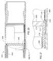
- FIG. 1is a cross section view of a downhole deployment valve (DDV) in a closed position, according to one embodiment of the invention.
- DDVdownhole deployment valve
- FIGS. 2 and 3are respectively cross section and side views of a control line connection at a first end of the DDV.
- FIG. 4is a cross section view of the DDV as shown in FIG. 1 after actuation to an open position.
- FIG. 5is a cross section view of an actuator sleeve receptacle at a second end of the (DDV).
- FIG. 6is an isometric view of the DDV coupled to an instrumentation sub, according to one embodiment of the invention.
- FIG. 7is a cross section view of another DDV in a closed position, according to one embodiment of the invention.
- FIG. 8is a cross section view of the DDV shown in FIG. 7 after actuation to an open position where a biasing member attached to a housing of the DDV contacts a valve member to initially facilitate closing of the valve member during return to the closed position.
- FIGS. 9 and 10are respectively isometric and partial cross section views of an alternative biasing mechanism, according to one embodiment of the invention, for a DDV to initially facilitate closing of a valve member during return to a closed position illustrated from an open position.
- FIG. 11is a cross section view of a DDV similar to that shown in FIGS. 9 and 10 after actuation to an open position where a band creates a pulling force on a valve member to initially facilitate closing of the valve member during return to a closed position.
- FIG. 12is a cross section view of a DDV with a sealing element disposed at an interface between a valve member and a valve seat, according to one embodiment of the invention.
- FIG. 13is an enlarged cross section view of the interface between the valve member and the valve seat shown in FIG. 12 .
- FIG. 14is an isometric view of the valve seat member illustrated in FIG. 12 .
- FIG. 15is an isometric view of a DDV in an open position with closing springs coupled to a valve member by intermediary rods having a relatively smaller profile than a diameter of the springs, according to one embodiment of the invention.
- FIG. 16is cross section views of various possible interfaces between a valve member and a valve seat for utilization with a DDV, according to one embodiment of the invention.
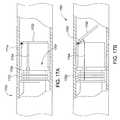
- FIGS. 17A and 17Bare partial cross section views of respectively a DDV in a closed position and a DDV in a partial open position, which function by a biased closure mechanism operating under compression, according to embodiments of the invention.
- FIG. 18is a cross section view of a DDV secured in a closed position by an engaging mechanism that is coupled to an actuating sleeve of the DDV and in contact with a backside of a valve member in the closed position, according to one embodiment of the invention.
- FIG. 19is a cross section view of the DDV as shown in FIG. 18 after actuation to an open position.
- FIG. 20is a cross section view of a DDV secured in a closed position by another engaging mechanism that is deactivated by an actuating sleeve of the DDV and in contact with a backside of a valve member in the closed position, according to one embodiment of the invention.
- FIG. 21is an enlarged cross section view of the engaging mechanism shown in FIG. 20 .
- FIG. 22is a cross section view of a DDV positively actuated to a closed position by a linkage mechanism coupling an actuating sleeve of the DDV to a valve member, according to one embodiment of the invention.
- FIG. 23is a cross section view of the DDV as shown in FIG. 22 after actuation to an open position.
- FIG. 24is a cross section view of a DDV having a sealing element held in place by a compression ring, a rod actuating mechanism to operate the DDV from a closed position shown to an open position, and fluid passages to valve seat purging outlets, according to one embodiment of the invention.
- Embodiments of the inventiongenerally relate to isolating an interior first section of a casing string from an interior second section of the casing string.
- the casing stringmay include a downhole deployment valve (DDV) that has an outer housing.
- the housingmay form an intermediate portion of the casing string with cement disposed in an annular area between a borehole wall and an exterior surface of the casing string including an outside of the housing, depending on level of the cement in the annular area, to secure the casing string in the borehole.
- the DDVmay in any embodiment couple with a tie-back end, such as a polished bore receptacle, of a casing or liner that integrates with the DDV to form the casing string.
- a valve membersuch as a flapper valve within the DDV enables sealing between the first and second sections of the casing string such that pressure in the first section that is in fluid communication with a well surface may be bled off and open at the well surface while maintaining pressure in the second section of the casing string.
- FIG. 1shows a cross section view of a DDV 100 in a closed position due to a flapper 102 obstructing a longitudinal central bore 104 through the DDV 100 .
- the DDV 100further includes an outer housing 106 with an actuation sleeve 108 disposed concentrically within the housing 106 .
- the actuation sleeve 108represents an exemplary mechanism for moving the flapper 102 to open the DDV 100 although other types of actuators may be used in some embodiments.
- the sleeve 108slides within the housing 106 based on control signals received to selectively displace the flapper 102 due to movement of the sleeve 108 across an interface between the flapper 102 and a seat 110 . Biasing of the flapper 102 may return the flapper 102 into contact with the seat 110 upon withdrawal of the sleeve 108 .
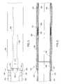
- FIGS. 2 and 3illustrate control line connections 200 at a first end 201 of the housing 106 where the DDV 100 couples to a first casing length 202 that extends to the well surface.
- the connections 200extend in a direction parallel with the longitudinal axis of the DDV 100 and are outlets for first and second bores 304 , 306 through the housing 106 .
- the bores 304 , 306provide fluid passage respectively to first and second piston chambers 208 , 210 defined between the housing 106 and the sleeve 108 . Fluid pressure supplied to the first piston chamber 208 moves the sleeve 108 in a first direction to open the DDV 100 .
- fluid pressure introduced into the second piston chamber 210acts on the sleeve 108 in an opposite second direction to slide the sleeve 108 out of interference with the flapper 102 .
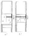
- the control line connections 200extend from the housing 106 at a longitudinal slot or recess 312 in an outer diameter of the housing 106 . Since the connections 200 are at the first end 201 of the housing 106 , a pin end 203 of the first casing length 202 extends into the first end 201 beyond the connections 200 for coupling the DDV 100 to the first casing length 202 .
- this arrangement for the connections 200 in combination with a control line protector 314guards the connections 200 and control lines coupled to the connections 200 from harmful effects such as abrasion and axial tension without detrimentally effecting pressure ratings of the DDV 100 .
- FIG. 3shows the control line protector 314 having a band clamp 316 and a protrusion 318 extending into the recess 312 in the housing 106 .
- the control line protector 314covers and retains the control lines attached to the control line connections 200 .
- Examples of the protector 314include any conventional cable protector such as may be utilized along the casing string between each joint.
- the protrusion 318 of the protectorrotationally keys the protector 314 relative to the housing 106 to prevent control line disengagement at the control line connections 200 due to potential rotation of the protector 314 .
- the band clamp 316secures around a recess 320 in an outer diameter of the first casing length 202 adjacent to the first end 201 of the housing 106 in order to further affix the protector 314 relative to the connections 200 .
- inner mating profiles 112 in the sleeve 108enable engagement of the sleeve 108 with a corresponding profile tool for manipulating the location of the sleeve 108 by mechanical force.
- This mechanical manipulationmay occur only after freeing the sleeve 108 from any possible hydraulic lock in the first or second chambers 208 , 210 as visible in FIG. 2 .
- a releasable sealing ring 222shear pins to an outside of the sleeve 108 to permit free movement of the sleeve 108 relative to the sealing ring 222 upon overcoming an identified force required to break attachment between the sealing ring 222 and the sleeve 108 .
- the sealing ring 222spans an annular area between the housing 106 and the sleeve 108 to define and isolate the first and second chambers 208 , 210 from one another.
- a releasable retaining ring 224also couples, by a shear pinned connection, to the outside of the sleeve 108 adjacent the sealing ring 222 within the second chamber 210 .
- the retaining ring 224surrounds a locking or expansion ring, such as a biased C-ring 226 , disposed around the sleeve 108 and maintains the C-ring 226 in a compressed state.
- the retaining ring 224moves with the sleeve 108 until abutting an inward facing shoulder 228 inside the housing 106 at which time connection between the retaining ring 224 and the sleeve 108 breaks.
- the sleeve 108carries the C-ring 226 to an interference groove 230 around the inside of the housing 106 where the C-ring 226 expands and is trapped to lock relative movement between the housing 108 and the sleeve 106 .
- the sleeve 108With the sleeve 108 moved to where the C-ring 226 is located at the interference groove 230 , the sleeve 108 extends through the interface between the flapper 102 and the seat 110 beyond where positioned when the DDV 100 is in an open position without being locked open.
- FIG. 4illustrates the DDV 100 after actuation to the open position to thereby enable tools such as a drill string to pass through the bore 104 of the DDV 100 .
- the sleeve 108pushes the flapper 108 pivotally away from the seat 110 and toward a wall of the housing 106 .
- the sleeve 108thus physically interferes with biasing of the flapper 108 toward the seat 110 .
- the sleeve 108covers the flapper 102 when the DDV is in the open position to at least inhibit debris and mud from collecting around the flapper 102 . Caking of mud between a backside surface of the flapper 102 and the housing 106 can cause the flapper 102 to stick in the open position after withdrawing the sleeve 108 out of interference with the flapper 102 .
- the flapper 102may include a secondary biasing member to facilitate initiating closure of the flapper 102 and hence mitigate effects associated with sticking open.
- the flapper 102may include a biasing member such as a spring metal strip 114 extending outwardly angled from the backside surface of the flapper 102 and located in some embodiments distal to a pivot point of the flapper 102 .
- the DDV 100 in the open positionpushes the spring metal strip 114 against the housing 106 causing the spring metal strip 114 to deflect. This deflection aids in kicking off return of the flapper 102 to the seat 110 after withdrawing the sleeve 108 out of interference with the flapper 102 .
- FIG. 5shows an optional actuator sleeve receptacle 500 at a second end 502 of the DDV 100 where a second casing length 504 extends further into the well beyond the DDV 100 .
- Shear pins 506secure the receptacle 500 within the housing 106 . Breaking the shear pins 506 permits longitudinal movement of the receptacle 500 to accommodate further movement of the sleeve 108 if desired to lock open the DDV 100 as described herein.
- the receptacle 500includes a sleeve interface end 508 , for example, any combination of a concave end, an end seal and a coated tip, corresponding to the sleeve 108 that may abut the interface end 508 when the DDV 100 is in the open position.
- An inward angled end 510 of the receptacle 500 opposite to the sleeve interface end 508acts to channel flow through the DDV 100 and divert flow from going outside of the sleeve 108 to where the flapper 102 is disposed in the open position.
- the sleeve receptacle 500As a result of the sleeve receptacle 500 influencing the flow, the sleeve receptacle 500 further aids in inhibiting build-up of debris around the flapper 102 leading to possible sticking open of the flapper 102 .
- FIG. 6illustrates an isometric view of the DDV 100 coupled to an instrumentation sub 600 , which may be integral with the DDV 100 and not a separate component in some embodiments.
- the instrumentation sub 600exemplifies modular component coupling with the DDV 100 .
- the instrumentation sub 600includes base tubing 602 , a shroud 604 covering the base tubing 602 , and sensors 606 .
- the shroud 604protects the sensors and a control line 608 .
- the sensors 606may enable taking temperature and/or pressure measurements above and/or below the flapper 102 .
- the sensors 606may couple via respective sensing lines to ports in pressure communication with an interior of the DDV 100 above and below the flapper 102 in a manner analogous to the connections 200 and the bores 304 , 306 (shown in FIG. 3 ) utilized in hydraulic actuation of the sleeve 108 .
- the sensors 606may define relay points receiving signals from pressure sensors disposed in the DDV 100 with the signals carried wirelessly or on fiber optic or electrical lines that may be run through channels also in a manner analogous to the connections 200 and the bores 304 , 306 .
- FIG. 7shows another DDV 700 in a closed position due to a flapper 702 being biased into contact with a seat 710 .
- the DDV 700includes a cage insert 701 disposed within a housing 706 of the DDV 700 .
- Controlled longitudinal movement of a sleeve 708functions to displace the flapper 702 .
- the sleeve 708includes an optional non-flat leading end 709 for contact with the flapper 702 .
- the leading end 709curves to protrude further toward the flapper 702 distal to a pivot point for the flapper 702 . Keying of the sleeve 708 thus may maintain rotational position of the sleeve 708 relative to the flapper 702 .
- Having the sleeve 708 initially contact the flapper 702 distal the pivot point due to the non-flat leading end 709facilitates and improves mechanical aspects of opening the DDV 700 since a mechanical advantage is achieved by force applied further from the pivot point of the flapper 702 .
- FIG. 8illustrates the DDV 700 after actuation to an open position where a biasing member shown as a spring metal strip 714 coupled to the housing 706 via the cage 701 contacts the flapper 702 to initially facilitate closing of the flapper 702 during return to the closed position.
- a biasing membershown as a spring metal strip 714 coupled to the housing 706 via the cage 701 contacts the flapper 702 to initially facilitate closing of the flapper 702 during return to the closed position.
- other biasing membersinclude spring washers, torsion springs, extension springs and levered springs.
- the spring metal strip 714then urges the flapper 702 away from the housing 706 for only a portion of pivotal travel of the flapper 702 to overcome any potential sticking with further urging provided by a primary closing force such as springs that are described herein and/or fluid pressure acting on a backside of the flapper 702 .
- FIGS. 9 and 10show a DDV 900 with a band 914 , such as an elastomer band, disposed around a cage 901 within a housing 906 of the DDV 900 to initially facilitate closing of a flapper 902 during return from an open position to a closed position that is illustrated.
- a band 914such as an elastomer band
- An open sided tube shape of the cage 901gives the cage 901 a partial circular cross section where the band 914 is located.
- the band 914hence defines a D-shape when the DDV 900 is in the closed position due to this configuration of the cage 901 .
- the cage 901positions a portion of the band 914 corresponding to a flat side of the D-shape within a travel path of the flapper 902 during operation between the closed and open positions such that the flapper 902 moves or stretches the band 914 in the open position.
- Recovery of the band 914ensures sufficient closing force is applied to the flapper 902 by boosting initial urging of the flapper 902 away from the housing 906 in which the flapper 902 opens toward.
- the band 914defines a coil spring, a scroll spring or a garter spring that enlarges in diameter due to temporary deformation upon movement of the flapper 902 to the open position.
- FIG. 11shows a DDV 1100 similar to that shown in FIGS. 9 and 10 after actuation to an open position.
- Another band having elastic or resilient properties formed with a spring section 1114 and a connecting section 1115such as a rope, a braided or solid metal band, or a metal band strip, creates a pulling force on a flapper 1102 when in the open position. This pulling force initially facilitates closing of the flapper 1102 during return to a closed position.
- FIGS. 10 and 11depict complete cross sectional views with the exception of banding used to pull the flappers 902 , 1102 .
- the DDV 100may include a flushing feature, in some embodiments, for washing the interface between the flapper 102 and the seat 110 .
- a flushing featurefor washing the interface between the flapper 102 and the seat 110 .
- Debris that is composed of hard, solid particles disposed in this interfacetends to hold the flapper 102 away from the seat 110 and create a leak path. Cutting of the DDV 100 at any such leak path further exacerbates the problem associated with the debris.
- the control line connections 200separate from ones of the connections 200 to the first and second bores 304 , 306 enable flushing using control line supplied fluid such as illustrated in FIG. 24 .
- Operation of the sleeve 108 in some embodimentacts as a syringe and plunger to push fluid past the flapper 102 during actuation from the closed position to the open position due to a wash seal 116 disposed on the sleeve 108 sealing between the sleeve 108 and the housing 106 .
- Close tolerance between the sleeve 108 and the housing 106 at the seat 110creates a nozzle effect facilitating the washing and removing of the debris.
- a fluid filled annular volume 118 between the sleeve 108 and the housing 106 along a length of the sleeve 116 that moves through the seat 110contains fluid (e.g., drilling fluid or mud) used in the washing.
- the wash seal 116moves down with the sleeve 108 during actuation to force the fluid within the annular volume 118 out around the seat 110 .
- Ports 120 through the sleeve 108 sized to limit particulate mattermay facilitate back filling of the annular volume 118 upon return to the closed position if the wash seal 116 is configured in a one-way manner. Since flushing occurs when opening, a method of operating the DDV 100 to take advantage of the flushing feature includes operating the DDV 100 through open-closed-open cycling to flush prior to final closing and isolation of pressure below the flapper 102 .
- FIGS. 12 and 13illustrate a DDV 1200 with a sealing element 1201 such as an elastomeric o-ring disposed at an interface between a valve member 1202 and a valve seat 1210 .
- a sealing element 1201such as an elastomeric o-ring disposed at an interface between a valve member 1202 and a valve seat 1210 .
- compressibility and deformability of the sealing element 1201helps to ensure that proper sealing occurs with the valve member 1202 even in the presence of small particles that would otherwise establish a leak path where the valve member 1202 is held off the valve seat 1210 .
- a seal groove 1301that may define a dovetail or other shape in the valve seat 1210 retains the sealing element 1201 , which may be analogously disposed on the valve member 1202 in some embodiments.
- valve member 1202must fit inside the DDV 1200 when the DDV is open without obstructing the bore through the DDV 1200 . This requirement dictates acceptable geometry options for the valve member 1202 .
- the valve seat 1210defines an elliptical shape as depicted by dashed line 1203 for mating engagement with the valve member 1202 in order to make the valve seat 1210 consistent in width at locations around the perimeter of the valve seat 1210 .
- the elliptical shapeprovides width of the valve seat 1210 to accommodate the seal groove 1301 at all points along the perimeter by avoiding variable narrowing of the valve seat 1210 inherent in other geometries.
- valve member 1202closes to a first stage with contact only occurring between the sealing member 1201 and the valve member 1202 .
- This contactoccurs squarely and completely around the sealing member 1201 in the first stage.
- a gap 1303closes once the valve member 1202 compresses the sealing member 1201 in closing to a second stage associated with higher pressure sealing than the first stage.
- transition between the first and second stagesoccurs via a biased sliding hinge member 1510 onto which the valve member 1202 pivotally secures.
- the sealing member 1201initiates sealing to enhance metal to metal sealing between the valve member 1202 and the valve seat 1210 that is established in the second stage.
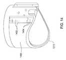
- FIG. 14illustrates a valve seat member 1400 that provides the valve seat 1210 shown in FIG. 12 .
- closing spring bores 1402 cutting into the outer diameter of the valve seat member 1400may terminate for some embodiments prior to reaching an end of the valve seat member 1400 where the valve seat 1210 is defined since extension of the closing spring bores 1402 to the end of the valve seat member 1400 may reduce the width of the valve seat 1210 at corresponding locations around the valve seat 1210 .
- intermediary recesses 1404that are relatively shallower than the closing spring bores 1402 extend from respective closing spring bores 1402 to the end of the valve seat member 1400 where the valve seat 1210 is defined.
- FIG. 15shows the DDV 1200 in an open position and incorporating the valve seat member 1400 , which is illustrated in FIG. 14 and visible in FIG. 15 due to an outer housing of the DDV 1200 being removed for explanation purposes.
- Closing springs 1501reside in respective ones of the closing spring bores 1402 .
- the closing springs 1501couple to the valve member 1202 by intermediary rods or plates 1503 having a relatively smaller cross sectional dimension than a diameter of the closing springs 1501 .
- the intermediary plates 1503may travel in respective ones of the intermediary recesses 1404 within the valve seat member 1400 during operation.
- a straightened extension 1505 of the closing springs 1501extends beyond the closing spring bores 1402 to couple with the valve member 1202 .
- the closing springs 1501pull on the valve member 1202 to urge the valve member 1202 toward the valve seat 1210 when the valve member 1202 is not held open by an actuating sleeve that is also not shown in FIG. 15 for explanation purposes.
- the sliding hinge member 1510also visible in FIG. 15 enables displacement of the pivoting point of the valve member 1202 longitudinally to permit transitioning between the first and second stages of the closed position, as described herein with reference to FIG. 13 .
- Screws 1512 inserted through respective longitudinal slots 1514 through the hinge member 1510 and received in the valve seat member 1400couple the hinge member 1510 to the valve seat member 1400 while permitting sliding motion of the hinge member 1510 relative to the valve seat member 1400 .
- Length of the slots 1514 or a hinge stop 1516interferes with movement of the hinge member 1510 in a first direction beyond a certain point, which may be associated with the closing to the first stage and accordingly displacing of the pivot point a furthest position from the valve seat 1210 .
- a biasing membersuch as a hinge member spring 1518 acts on an end 1520 of the hinge member 1510 to urge the hinge member 1510 toward the hinge stop 1516 .
- pressure on a backside of the valve member 1202 when closed to the first stagepushes the valve member 1202 and hence the hinge member 1510 against bias of the hinge member spring 1518 in order to close to the second stage. Movement of the pivot point due to the sliding hinge member 1510 maintains square mating with the valve seat 1210 in both the first and second stages.
- FIG. 16illustrates first through seventh valve member to valve seat interfaces 1601 - 1607 as examples of various options to be employed in some embodiments to improve sealing which may otherwise be compromised by debris.
- the DDV 100 shown in FIG. 1may utilize any one of the interfaces 1601 - 1605 by incorporating corresponding sides of the interfaces 1601 - 1605 on either or both of the flapper 102 and the seat 110 .
- the first interface 1601includes a sealing element 1610 formed of a resilient material such as an elastomer or a metal relatively soft compared to other metals making up the interface 1601 .
- the first interface 1601may additionally include a V-shaped feature 1612 to establish point loading around the interface 1601 . The V-shaped feature 1612 tends to cut through or push aside any debris at the interface 1601 .
- the second interface 1602includes a pointed protrusion 1614 alone.
- the pointed protrusion 1614may contact a non-metal surface such as a polymer or elastomer or a metal surface relatively soft compared to the pointed protrusion 1614 .
- the third interface 1603includes a preformed V-profile 1618 to mate with a V-extension 1616 .
- the fourth interface 1604employs progressively less steep inclines 1622 for mismatched interference engagement with angled projection 1620 such that progressive line contact occurs throughout use.
- the fifth interface 1605illustrates an example of mating flats and tapers due to a stepped concave feature 1624 mating with a corresponding convex feature 1626 .
- the sixth interface 1606includes a metal and plastic combination seal 1628 .
- a plastic jacket 1630 outside and connecting first and second helical springs 1632 , 1634yields during compression and allows the combination seal 1628 to conform to surface irregularities.
- a trapping recess 1636 in which the second helical spring 1634 is heldretains the combination seal 1628 in place at the sixth interface 1606 .
- the seventh interface 1607includes an optionally pointed seat ring 1638 biased to engage an opposing surface.
- the seat ring 1638slides within a trough 1640 to longitudinal positions corresponding to where seating contact occurs.
- a ring seal 1642prevents passage of fluid around the seat ring 1638 within the trough 1640 .
- a seat ring biasing element 1644pushes the seat ring 1638 out of the trough 1640
- a pin 1646 fixed relative to the trough 1640engages a slide limiting groove 1648 in the seat ring 1638 to retain the seat ring 1638 in the trough 1640 .
- FIG. 17Ashows a DDV 1700 in a closed position as maintained by a biased closure mechanism 1701 operating under compression.
- a biasing membersuch as a coil spring 1703 disposed around a valve seat body 1714 functions under compression to pivotally urge a flapper 1702 against the valve seat body 1714 and hence close the DDV 1700 .
- a linkage arm 1704couples the flapper 1702 with the coil spring 1703 and traverses the interface between the valve seat body 1714 and the flapper 1702 without reducing surface area sealing contact of the flapper 1702 .
- a cableforms the linkage arm 1704 that may be disposed beyond a midpoint of the flapper 1702 toward a distal end of the flapper relative to a pivot point of the flapper 1702 . As the distance from the pivot point increases, the moment increases that is applied by the spring 1703 so that the flapper 1702 may more securely shut from just the force of the spring 1703 .
- FIG. 17Bshows a DDV 1751 in a partial open position and similar to the DDV 1700 shown in FIG. 17A such that most like parts are not labeled or further described.
- a linkage cable 1754couples a flapper 1752 with a coil spring 1753 .
- a cable guide or cam 1757aligns or supports the cable 1754 and may be moveable with movement of the flapper 1752 .
- FIG. 18illustrates a DDV 1800 secured in a closed position by a chock 1805 coupled to an actuating sleeve 1808 of the DDV 1800 by a tether 1803 .
- a first end of the tether 1803secures to the sleeve 1808 .
- the tether 1803then passes across a valve seat 1810 so that a second end of the tether 1803 affixes to the chock 1805 .
- Tension in the tether 1803 due to location of the sleeve 1808 while the DDV 1800 is in the closed positiondisposes the chock 1805 against a backside of the flapper 1802 .
- Actuation of the sleeve 1808augments biasing of the flapper 1802 to push the flapper against the seat at final closing of the flapper 1802 and locks the flapper 1802 in position while the DDV 1800 is closed. Forces acting on the flapper 1802 that overcome the bias of the flapper 1802 fail to open the flapper 1802 unless the sleeve is moved to release the chock 1805 .
- FIG. 19shows a cross section view of the DDV 1800 after actuation to an open position. Movement of the sleeve 1808 toward the flapper 1802 releases tension in the tether 1803 and allows the chock 1805 to clear from interference with pivoting motion of the flapper 1802 . Subsequent contact of the sleeve 1808 with the flapper 1802 in the open position then displaces the flapper 1802 from the seat 1810 against closing bias of the flapper 1802 .
- FIGS. 20 and 21illustrate a DDV 2000 secured in a closed position by a blocking lever 2102 that is disengaged by sliding movement of an actuating sleeve 2008 of the DDV 2000 .
- a portion of the lever 2102contacts a backside of a valve member 2002 to positively latch the valve member 2002 secured against a valve seat 2110 without reliance on biasing of the valve member 2002 to maintain sealing contact between the valve seat 2110 and the valve member 2002 .
- a biasing element 2104forces the lever 2102 away from a housing 2006 of the DDV 2000 when the sleeve 2008 is actuated to a position retracted away from interference with the valve member 2002 .
- movement of the sleeve 2008 toward the valve member 2002disengages the lever 2102 from interference with pivoting motion of the valve member 2002 .
- the lever 2102pivotally couples to a cage insert 2101 in the housing 2006 through which the valve member 2002 opens.
- the lever 2102extends beyond the valve seat 2110 to a button 2100 that passes through an aperture in a wall of a valve seat body 2114 . Sealed sliding movement of the button 2100 relative to the valve seat body 2114 translates pivotal motion to the lever 2102 that is biased by the biasing element 2104 in a manner that urges the button 2100 in a radial inward direction to an activated position.
- the button 2100extends in the activated position within a path of the sleeve 2008 during movement of the sleeve 2008 to open the DDV 2000 .
- the sleeve 2008contacts the button 2100 forcing the button 2100 in a radial outward direction and to a deactivated position out of the path of the sleeve 2008 .
- This movement of the button 2100moves the lever 2102 closer to the housing 2006 against bias of the biasing element 2104 and hence away from contact with the valve member 2002 .
- Continued movement of the sleeve 2008then displaces the valve member 2002 that is no longer secured or locked in position by the lever 2102 .
- FIG. 22illustrates a cross section view of a DDV 2200 positively actuated to a closed position by a linkage 2201 coupling an actuating sleeve 2208 of the DDV 2200 to a valve member 2202 .
- the linkage 2201may include a cable, wire, chain and/or rigid rods having ends affixed respectively to the sleeve 2208 and the valve member 2202 .
- affixing the linkage 2201 farther from a pivot point of the valve member 2202produces a larger moment about the pivot point than the same force positioned closer to the pivot point.
- the linkage 2201enables mechanically pushing/pulling the valve member 2202 to a desired position.
- actuation of the sleeve 2208augments biasing of the valve member 2202 to pull the valve member 2202 against a seat 2210 .
- Active actuation to close the DDV 2200 by controlled amount of force that may be maintained on the valve member 2202 to hold the valve member 2202 against the seat 2210occurs based on tension supplied to the linkage 2201 by actuation of the sleeve 2208 .
- FIG. 23shows a cross section view of the DDV 2200 after actuation to the open position.
- the sleeve 2208moves through the valve seat 2210 to displace the valve member 2202 .
- the linkage 2201travels with the sleeve 2208 releasing tension in the linkage 2201 and enabling pivoting of the valve member 2202 .
- FIG. 24illustrates a DDV 2400 having a flapper 2402 biased into sealing engagement against a valve seat 2410 .
- the DDV 2400further includes a sealing element such as a polytetrafluoroethylene tubular insert 2413 held in place within a valve seat body 2414 by a compression ring 2411 that sandwiches the insert 2413 against an inner diameter of the valve seat body 2414 at the valve seat 2410 such that the flapper 2402 contacts the insert 2413 .
- first fluid porting 2418provides washing fluid through seat purge passages discharging along or adjacent the valve seat 2410 for washing any debris from an interface between the valve seat 2410 and the flapper 2402 .
- Second fluid porting 2409introduces pressurized fluid to a rod actuator 2408 in some embodiments.
- the first fluid porting 2418 and the second fluid porting 2409may each connect to surface through a control line coupled to the DDV 2400 .
- One end of the rod actuator 2408contacts some flapper assembly surface, such as the flapper 2402 , offset from a pivot point of the flapper 2402 , such as between the pivot point and the valve seat 2410 .
- the rod actuator 2408slides longitudinally in response to the pressurized fluid to operate the DDV 2400 from a closed position shown to an open position.
- a portion of the second fluid porting 2409defines a bore in the valve seat member 2414 in which the rod actuator 2408 is disposed. Bias of the flapper 2402 returns the rod actuator 2408 to a retracted position within the second fluid porting 2409 upon closure of the flapper 2402 in absence of pressurized fluid supplied to the second fluid porting 2409 .
- designs discussed heretoforeinclude various aspects or features which may be combined with or implemented separately from one another in different arrangements, for some embodiments. These aspects that work in combination include any that do not interfere with one another as evident by the foregoing.
- any DDVmay benefit from one of the seat seals as discussed herein, may incorporate secondary biasing mechanisms to facilitate initiating valve member closure, may include valve seat jet washing ability, and/or provide positive lock closed positions. Such independent variations in contemplated embodiments may depend on particular applications in which the DDV is implemented.
Landscapes
- Engineering & Computer Science (AREA)
- Geology (AREA)
- Life Sciences & Earth Sciences (AREA)
- Mining & Mineral Resources (AREA)
- Physics & Mathematics (AREA)
- Environmental & Geological Engineering (AREA)
- Fluid Mechanics (AREA)
- General Life Sciences & Earth Sciences (AREA)
- Geochemistry & Mineralogy (AREA)
- Mechanical Engineering (AREA)
- Lift Valve (AREA)
- Mechanically-Actuated Valves (AREA)
- Fluid-Driven Valves (AREA)
Abstract
Description
Claims (21)
Priority Applications (6)
| Application Number | Priority Date | Filing Date | Title |
|---|---|---|---|
| US12/098,264US8261836B2 (en) | 2007-04-04 | 2008-04-04 | Downhole deployment valves |
| US13/608,740US8522878B2 (en) | 2007-04-04 | 2012-09-10 | Downhole deployment valves |
| US13/608,784US8534362B2 (en) | 2007-04-04 | 2012-09-10 | Downhole deployment valves |
| US13/608,767US8544549B2 (en) | 2007-04-04 | 2012-09-10 | Downhole deployment valves |
| US13/960,621US8789603B2 (en) | 2007-04-04 | 2013-08-06 | Downhole deployment valves |
| US14/324,855US8905140B2 (en) | 2007-04-04 | 2014-07-07 | Downhole deployment valves |
Applications Claiming Priority (2)
| Application Number | Priority Date | Filing Date | Title |
|---|---|---|---|
| US91012907P | 2007-04-04 | 2007-04-04 | |
| US12/098,264US8261836B2 (en) | 2007-04-04 | 2008-04-04 | Downhole deployment valves |
Related Child Applications (3)
| Application Number | Title | Priority Date | Filing Date |
|---|---|---|---|
| US13/608,740DivisionUS8522878B2 (en) | 2007-04-04 | 2012-09-10 | Downhole deployment valves |
| US13/608,784DivisionUS8534362B2 (en) | 2007-04-04 | 2012-09-10 | Downhole deployment valves |
| US13/608,767DivisionUS8544549B2 (en) | 2007-04-04 | 2012-09-10 | Downhole deployment valves |
Publications (2)
| Publication Number | Publication Date |
|---|---|
| US20080245531A1 US20080245531A1 (en) | 2008-10-09 |
| US8261836B2true US8261836B2 (en) | 2012-09-11 |
Family
ID=39522309
Family Applications (6)
| Application Number | Title | Priority Date | Filing Date |
|---|---|---|---|
| US12/098,264Active2030-06-26US8261836B2 (en) | 2007-04-04 | 2008-04-04 | Downhole deployment valves |
| US13/608,740ActiveUS8522878B2 (en) | 2007-04-04 | 2012-09-10 | Downhole deployment valves |
| US13/608,784ActiveUS8534362B2 (en) | 2007-04-04 | 2012-09-10 | Downhole deployment valves |
| US13/608,767ActiveUS8544549B2 (en) | 2007-04-04 | 2012-09-10 | Downhole deployment valves |
| US13/960,621ActiveUS8789603B2 (en) | 2007-04-04 | 2013-08-06 | Downhole deployment valves |
| US14/324,855ActiveUS8905140B2 (en) | 2007-04-04 | 2014-07-07 | Downhole deployment valves |
Family Applications After (5)
| Application Number | Title | Priority Date | Filing Date |
|---|---|---|---|
| US13/608,740ActiveUS8522878B2 (en) | 2007-04-04 | 2012-09-10 | Downhole deployment valves |
| US13/608,784ActiveUS8534362B2 (en) | 2007-04-04 | 2012-09-10 | Downhole deployment valves |
| US13/608,767ActiveUS8544549B2 (en) | 2007-04-04 | 2012-09-10 | Downhole deployment valves |
| US13/960,621ActiveUS8789603B2 (en) | 2007-04-04 | 2013-08-06 | Downhole deployment valves |
| US14/324,855ActiveUS8905140B2 (en) | 2007-04-04 | 2014-07-07 | Downhole deployment valves |
Country Status (3)
| Country | Link |
|---|---|
| US (6) | US8261836B2 (en) |
| EP (7) | EP2535507B1 (en) |
| CA (3) | CA2627838C (en) |
Cited By (10)
| Publication number | Priority date | Publication date | Assignee | Title |
|---|---|---|---|---|
| US20120012202A1 (en)* | 2010-07-14 | 2012-01-19 | Weatherford/Lamb, Inc. | Irregularly Shaped Flapper Closure and Sealing Surfaces |
| US20120024537A1 (en)* | 2010-07-29 | 2012-02-02 | Mcdowell Christopher L | Isolation valve with debris control and flow tube protection |
| US20120279701A1 (en)* | 2011-05-03 | 2012-11-08 | Baker Hughes Incorporated | Locking Assembly for Mechanically Set Packer |
| US20130008667A1 (en)* | 2007-04-04 | 2013-01-10 | Joe Noske | Downhole deployment valves |
| WO2014113280A2 (en) | 2013-01-18 | 2014-07-24 | Weatherford/Lamb, Inc. | Bidirectional downhole isolation valve |
| US9784073B2 (en) | 2004-11-23 | 2017-10-10 | Weatherford Technology Holdings, Llc | Rotating control device docking station |
| US10132137B2 (en) | 2013-06-26 | 2018-11-20 | Weatherford Technology Holdings, Llc | Bidirectional downhole isolation valve |
| US20210062616A1 (en)* | 2019-08-26 | 2021-03-04 | Halliburton Energy Services, Inc. | Flapper disk for buoyancy assisted casing equipment |
| US11261980B2 (en)* | 2020-03-12 | 2022-03-01 | Coil Solutions, Inc. | Apparatus and method for activation of flapper check valve |
| US12163403B1 (en)* | 2023-10-04 | 2024-12-10 | Halliburton Energy Services, Inc. | Flow tube and flapper configuration of a safety valve for a production wellbore |
Families Citing this family (54)
| Publication number | Priority date | Publication date | Assignee | Title |
|---|---|---|---|---|
| US7836946B2 (en) | 2002-10-31 | 2010-11-23 | Weatherford/Lamb, Inc. | Rotating control head radial seal protection and leak detection systems |
| US8826988B2 (en) | 2004-11-23 | 2014-09-09 | Weatherford/Lamb, Inc. | Latch position indicator system and method |
| GB0525672D0 (en)* | 2005-12-16 | 2006-01-25 | Novartis Ag | Organic compounds |
| US7762336B2 (en)* | 2006-06-12 | 2010-07-27 | Weatherford/Lamb, Inc. | Flapper latch |
| CA2581581C (en)* | 2006-11-28 | 2014-04-29 | T-3 Property Holdings, Inc. | Direct connecting downhole control system |
| US8196649B2 (en) | 2006-11-28 | 2012-06-12 | T-3 Property Holdings, Inc. | Thru diverter wellhead with direct connecting downhole control |
| DE102007036783A1 (en)* | 2007-08-03 | 2009-02-05 | Robert Bosch Gmbh | Hand tool with a dust extraction device |
| US7997345B2 (en) | 2007-10-19 | 2011-08-16 | Weatherford/Lamb, Inc. | Universal marine diverter converter |
| US8844652B2 (en) | 2007-10-23 | 2014-09-30 | Weatherford/Lamb, Inc. | Interlocking low profile rotating control device |
| US8286734B2 (en) | 2007-10-23 | 2012-10-16 | Weatherford/Lamb, Inc. | Low profile rotating control device |
| US20090229829A1 (en)* | 2008-03-17 | 2009-09-17 | Hemiwedge Valve Corporation | Hydraulic Bi-Directional Rotary Isolation Valve |
| US9784057B2 (en)* | 2008-04-30 | 2017-10-10 | Weatherford Technology Holdings, Llc | Mechanical bi-directional isolation valve |
| US9359853B2 (en) | 2009-01-15 | 2016-06-07 | Weatherford Technology Holdings, Llc | Acoustically controlled subsea latching and sealing system and method for an oilfield device |
| US8322432B2 (en) | 2009-01-15 | 2012-12-04 | Weatherford/Lamb, Inc. | Subsea internal riser rotating control device system and method |
| US8205637B2 (en)* | 2009-04-30 | 2012-06-26 | Baker Hughes Incorporated | Flow-actuated actuator and method |
| US7967076B2 (en)* | 2009-05-20 | 2011-06-28 | Baker Hughes Incorporated | Flow-actuated actuator and method |
| US8047293B2 (en)* | 2009-05-20 | 2011-11-01 | Baker Hughes Incorporated | Flow-actuated actuator and method |
| US8671974B2 (en)* | 2009-05-20 | 2014-03-18 | Baker Hughes Incorporated | Flow-actuated actuator and method |
| US8347983B2 (en) | 2009-07-31 | 2013-01-08 | Weatherford/Lamb, Inc. | Drilling with a high pressure rotating control device |
| US8347982B2 (en) | 2010-04-16 | 2013-01-08 | Weatherford/Lamb, Inc. | System and method for managing heave pressure from a floating rig |
| EP2576958B1 (en)* | 2010-05-24 | 2018-09-12 | Blackhawk Specialty Tools, LLC | Large bore auto-fill float equipment |
| US9175542B2 (en) | 2010-06-28 | 2015-11-03 | Weatherford/Lamb, Inc. | Lubricating seal for use with a tubular |
| US9386870B2 (en)* | 2010-07-19 | 2016-07-12 | Caesar Rossitto | Check valve drinking device |
| BR112013008051B1 (en) | 2010-09-20 | 2020-04-07 | Weatherford/Lamb, Inc. | method of operating an isolation valve in a well hole and isolation assembly for use in a well hole |
| US8978750B2 (en) | 2010-09-20 | 2015-03-17 | Weatherford Technology Holdings, Llc | Signal operated isolation valve |
| RU2445445C1 (en)* | 2010-10-18 | 2012-03-20 | Дмитрий Иванович Александров | Self-contained shutoff device |
| GB2489267B (en)* | 2011-03-23 | 2015-06-10 | David Bell Conner | Wellbore valve assembly |
| US9068661B2 (en)* | 2012-06-06 | 2015-06-30 | Baker Hughes Incorporated | Curved flapper seal with stepped intermediate surface |
| WO2015020634A1 (en)* | 2013-08-06 | 2015-02-12 | Halliburton Energy Services, Inc. | Wave spring flapper closure mechanism |
| US9650884B2 (en) | 2013-09-20 | 2017-05-16 | Weatherford Technology Holdings, Llc | Use of downhole isolation valve to sense annulus pressure |
| US10787900B2 (en) | 2013-11-26 | 2020-09-29 | Weatherford Technology Holdings, Llc | Differential pressure indicator for downhole isolation valve |
| US9416621B2 (en)* | 2014-02-08 | 2016-08-16 | Baker Hughes Incorporated | Coiled tubing surface operated downhole safety/back pressure/check valve |
| US20160047209A1 (en)* | 2014-08-18 | 2016-02-18 | Baker Hughes Incorporated | Fullbore Wireline Pumpthrough Tool |
| US20160097243A1 (en)* | 2014-10-02 | 2016-04-07 | Ge Oil & Gas Esp, Inc. | Extra Low Profile Cable Protectors |
| CN104533343B (en)* | 2015-01-16 | 2016-12-21 | 苏州海德石油工具有限公司 | It is automatically switched off casing valve |
| GB2556756B (en)* | 2015-09-24 | 2020-02-12 | Halliburton Energy Services Inc | Float valve assembly with drag force dependent deactivation |
| CN106996279B (en)* | 2017-06-02 | 2023-05-23 | 成都市卓新实业有限公司 | Self-grouting back-pressure valve |
| US10513904B2 (en)* | 2017-06-30 | 2019-12-24 | Weatherford Technology Holdings, Llc | Provision of internal lines in a well tool |
| US10794143B2 (en)* | 2017-10-06 | 2020-10-06 | Baker Hughes, A Ge Company, Llc | Sub-surface safety valve flapper sleeve |
| US10009375B1 (en) | 2017-12-01 | 2018-06-26 | KnowBe4, Inc. | Systems and methods for artificial model building techniques |
| CA3051430A1 (en)* | 2019-08-08 | 2021-02-08 | Paul J. J. Grenier | Flomax closure element |
| CN110552662B (en)* | 2019-10-20 | 2024-06-11 | 上海达坦能源科技股份有限公司 | A ball-throwing fracturing sliding sleeve for fracturing |
| US11215026B2 (en) | 2020-06-02 | 2022-01-04 | Baker Hughes Oilfield Operations Llc | Locking backpressure valve |
| US11365605B2 (en) | 2020-06-02 | 2022-06-21 | Baker Hughes Oilfield Operations Llc | Locking backpressure valve |
| US11215031B2 (en) | 2020-06-02 | 2022-01-04 | Baker Hughes Oilfield Operations Llc | Locking backpressure valve with shiftable valve sleeve |
| US11230906B2 (en) | 2020-06-02 | 2022-01-25 | Baker Hughes Oilfield Operations Llc | Locking backpressure valve |
| US11215028B2 (en) | 2020-06-02 | 2022-01-04 | Baker Hughes Oilfield Operations Llc | Locking backpressure valve |
| US11359460B2 (en)* | 2020-06-02 | 2022-06-14 | Baker Hughes Oilfield Operations Llc | Locking backpressure valve |
| US11215030B2 (en) | 2020-06-02 | 2022-01-04 | Baker Hughes Oilfield Operations Llc | Locking backpressure valve with shiftable valve seat |
| CN111706295B (en)* | 2020-07-14 | 2021-03-23 | 西南石油大学 | Radio electromagnetic wave direct-current control pressure-relief sleeve valve |
| US11506020B2 (en) | 2021-03-26 | 2022-11-22 | Halliburton Energy Services, Inc. | Textured resilient seal for a subsurface safety valve |
| GB2608403B (en)* | 2021-06-30 | 2023-09-20 | Downhole Tools Int | Resisting leakage from a downhole tool string |
| CN113882820B (en)* | 2021-12-08 | 2022-02-22 | 西南石油大学 | Blowout prevention valve in drilling tool |
| WO2025128076A1 (en)* | 2023-12-11 | 2025-06-19 | Halliburton Energy Services, Inc. | Curved flow tube to slow a closure of a flow valve |
Citations (14)
| Publication number | Priority date | Publication date | Assignee | Title |
|---|---|---|---|---|
| GB240516A (en) | 1924-06-04 | 1925-10-05 | Charles Stewart Hastings Snow | Improvements in two-stroke cycle internal combustion engines |
| US4161985A (en)* | 1978-07-07 | 1979-07-24 | The Dow Chemical Company | Tool for removing fluids and loose material from an earth formation |
| US4294314A (en) | 1979-12-31 | 1981-10-13 | Hydril Company | Inside blowout preventer well tool |
| US4624315A (en) | 1984-10-05 | 1986-11-25 | Otis Engineering Corporation | Subsurface safety valve with lock-open system |
| US4846281A (en) | 1987-08-27 | 1989-07-11 | Otis Engineering Corporation | Dual flapper valve assembly |
| US5137090A (en) | 1991-05-03 | 1992-08-11 | Ava International Corporation | Subsurface tubing safety valve |
| GB2297572A (en) | 1995-02-03 | 1996-08-07 | Petroleum Eng Services | Subsurface valve |
| EP0915230A2 (en) | 1997-11-10 | 1999-05-12 | Halliburton Energy Services, Inc. | Safety valve utilizing an isolation valve |
| US6209663B1 (en) | 1998-05-18 | 2001-04-03 | David G. Hosie | Underbalanced drill string deployment valve method and apparatus |
| US6227299B1 (en) | 1999-07-13 | 2001-05-08 | Halliburton Energy Services, Inc. | Flapper valve with biasing flapper closure assembly |
| US20020070028A1 (en) | 2000-12-08 | 2002-06-13 | Garcia Christian D. | Debris free valve apparatus |
| GB2405165A (en) | 2003-08-18 | 2005-02-23 | Halliburton Energy Serv Inc | Safety valve having extension spring closure mechanism |
| US7537062B2 (en)* | 2006-08-14 | 2009-05-26 | Sunstone Corporation | Flapper valve and actuator |
| US20100294502A1 (en)* | 2009-05-19 | 2010-11-25 | Xu Richard Y | Magnetic Flapper Shock Absorber |
Family Cites Families (39)
| Publication number | Priority date | Publication date | Assignee | Title |
|---|---|---|---|---|
| US1899121A (en)* | 1931-03-26 | 1933-02-28 | Lyle C Tilbury | Back pressure valve mechanism for well pipe |
| US1950328A (en)* | 1932-06-09 | 1934-03-06 | John R Scohy | Valve release |
| US2698054A (en)* | 1949-01-31 | 1954-12-28 | Brown | Method of and apparatus for lowering pipe within a well bore |
| US2849207A (en)* | 1956-01-30 | 1958-08-26 | Baker Oil Tools Inc | Subsurface well bore valve apparatus |
| US3016955A (en)* | 1957-07-01 | 1962-01-16 | Page Oil Tools Inc | Fluid pressure actuated well shut-off valve |
| US3151839A (en) | 1962-04-16 | 1964-10-06 | Cicero C Brown | Two-way flapper-type valve |
| US3533430A (en)* | 1969-01-01 | 1970-01-01 | Otis Eng Corp | Shuttle valve |
| US4154303A (en)* | 1978-02-13 | 1979-05-15 | The Dow Chemical Company | Valve assembly for controlling liquid flow in a wellbore |
| US4254836A (en)* | 1978-04-10 | 1981-03-10 | Russell Larry R | Methods and apparatus for controlling fluid flow |
| US4254839A (en) | 1979-06-21 | 1981-03-10 | Dresser Industries, Inc. | Radial force anti-extrusion device for sealed drill string unit |
| IT1137690B (en)* | 1980-07-17 | 1986-09-10 | Inst Burovoi Tekhnik | VALVE DEVICE |
| US4378818A (en)* | 1980-12-17 | 1983-04-05 | Cormier Jr Arthur J | Well drilling float valve |
| US4415036A (en)* | 1982-02-22 | 1983-11-15 | Baker Oil Tools, Inc. | Pressure equalizing flapper type safety valve for subterranean wells |
| US4586534A (en)* | 1984-04-23 | 1986-05-06 | Daniel Industries | Check valve mechanism |
| GB2172031B (en)* | 1985-03-07 | 1988-03-16 | Halliburton Co | An inverse differential casing cementing float valve |
| US4727939A (en)* | 1987-02-10 | 1988-03-01 | Schlumberger Technology Corporation | Tool for closing a production column in a well |
| US4729432A (en)* | 1987-04-29 | 1988-03-08 | Halliburton Company | Activation mechanism for differential fill floating equipment |
| GB2257186B (en)* | 1990-07-13 | 1994-09-07 | Otis Eng Co | Method of completing and maintaining a well |
| US5145005A (en)* | 1991-04-26 | 1992-09-08 | Otis Engineering Corporation | Casing shut-in valve system |
| US5201371A (en)* | 1991-05-03 | 1993-04-13 | Allen Charles W | Back pressure flapper valve |
| US5141020A (en)* | 1991-09-30 | 1992-08-25 | Dover Corporation | Emergency vent valves for storage tanks |
| US5388622A (en)* | 1993-11-03 | 1995-02-14 | Ebw, Inc. | Automatic shutoff valve |
| EP0877853A2 (en) | 1996-02-03 | 1998-11-18 | Ocre (Scotland) Limited | Downhole valve |
| CA2181671A1 (en)* | 1996-07-19 | 1998-01-20 | Rick Picher | Downhole two-way check valve |
| US6263910B1 (en)* | 1999-05-11 | 2001-07-24 | Halliburton Energy Services, Inc. | Valve with secondary load bearing surface |
| CA2389621A1 (en)* | 1999-11-16 | 2001-05-25 | Schlumberger Canada Limited | Downhole valve |
| US7255178B2 (en)* | 2000-06-30 | 2007-08-14 | Bj Services Company | Drillable bridge plug |
| US6808020B2 (en)* | 2000-12-08 | 2004-10-26 | Schlumberger Technology Corporation | Debris-free valve apparatus and method of use |
| US6725935B2 (en)* | 2001-04-17 | 2004-04-27 | Halliburton Energy Services, Inc. | PDF valve |
| US6666271B2 (en)* | 2001-11-01 | 2003-12-23 | Weatherford/Lamb, Inc. | Curved flapper and seat for a subsurface saftey valve |
| CA2425724C (en)* | 2002-04-16 | 2006-01-31 | Schlumberger Canada Limited | Tubing fill and testing valve |
| US6877564B2 (en)* | 2002-09-30 | 2005-04-12 | Baker Hughes Incorporated | Flapper closure mechanism |
| US7178599B2 (en)* | 2003-02-12 | 2007-02-20 | Weatherford/Lamb, Inc. | Subsurface safety valve |
| US7255174B2 (en) | 2003-07-16 | 2007-08-14 | Baker Hughes Incorporated | Cement control ring |
| US7789156B2 (en) | 2004-06-24 | 2010-09-07 | Renovus Limited | Flapper valve for use in downhole applications |
| US20060283791A1 (en)* | 2005-06-17 | 2006-12-21 | Ross Colby M | Filter valve for fluid loss device |
| US7762336B2 (en)* | 2006-06-12 | 2010-07-27 | Weatherford/Lamb, Inc. | Flapper latch |
| CA2627838C (en)* | 2007-04-04 | 2011-09-20 | Weatherford/Lamb, Inc. | Downhole deployment valves |
| US20090151924A1 (en)* | 2007-12-12 | 2009-06-18 | Baker Hughes Incorporated | Downhole tool with shape memory alloy actuator |
- 2008
- 2008-03-31CACA2627838Apatent/CA2627838C/enactiveActive
- 2008-03-31EPEP12183774.4Apatent/EP2535507B1/enactiveActive
- 2008-03-31CACA2744842Apatent/CA2744842C/enactiveActive
- 2008-03-31EPEP20080153771patent/EP1980711B1/enactiveActive
- 2008-03-31EPEP20120183775patent/EP2535508B1/enactiveActive
- 2008-03-31CACA2940068Apatent/CA2940068C/enactiveActive
- 2008-03-31EPEP13172554.1Apatent/EP2650467B1/enactiveActive
- 2008-03-31EPEP20120183769patent/EP2535505B1/enactiveActive
- 2008-03-31EPEP20120183750patent/EP2535504B1/enactiveActive
- 2008-03-31EPEP20120183771patent/EP2535506B1/enactiveActive
- 2008-04-04USUS12/098,264patent/US8261836B2/enactiveActive
- 2012
- 2012-09-10USUS13/608,740patent/US8522878B2/enactiveActive
- 2012-09-10USUS13/608,784patent/US8534362B2/enactiveActive
- 2012-09-10USUS13/608,767patent/US8544549B2/enactiveActive
- 2013
- 2013-08-06USUS13/960,621patent/US8789603B2/enactiveActive
- 2014
- 2014-07-07USUS14/324,855patent/US8905140B2/enactiveActive
Patent Citations (15)
| Publication number | Priority date | Publication date | Assignee | Title |
|---|---|---|---|---|
| GB240516A (en) | 1924-06-04 | 1925-10-05 | Charles Stewart Hastings Snow | Improvements in two-stroke cycle internal combustion engines |
| US4161985A (en)* | 1978-07-07 | 1979-07-24 | The Dow Chemical Company | Tool for removing fluids and loose material from an earth formation |
| US4294314A (en) | 1979-12-31 | 1981-10-13 | Hydril Company | Inside blowout preventer well tool |
| US4624315A (en) | 1984-10-05 | 1986-11-25 | Otis Engineering Corporation | Subsurface safety valve with lock-open system |
| US4846281A (en) | 1987-08-27 | 1989-07-11 | Otis Engineering Corporation | Dual flapper valve assembly |
| US5137090A (en) | 1991-05-03 | 1992-08-11 | Ava International Corporation | Subsurface tubing safety valve |
| GB2297572A (en) | 1995-02-03 | 1996-08-07 | Petroleum Eng Services | Subsurface valve |
| EP0915230A2 (en) | 1997-11-10 | 1999-05-12 | Halliburton Energy Services, Inc. | Safety valve utilizing an isolation valve |
| US6209663B1 (en) | 1998-05-18 | 2001-04-03 | David G. Hosie | Underbalanced drill string deployment valve method and apparatus |
| US6227299B1 (en) | 1999-07-13 | 2001-05-08 | Halliburton Energy Services, Inc. | Flapper valve with biasing flapper closure assembly |
| US20020070028A1 (en) | 2000-12-08 | 2002-06-13 | Garcia Christian D. | Debris free valve apparatus |
| GB2405165A (en) | 2003-08-18 | 2005-02-23 | Halliburton Energy Serv Inc | Safety valve having extension spring closure mechanism |
| US20050039922A1 (en) | 2003-08-18 | 2005-02-24 | Vick James D. | Safety valve having extension spring closure mechanism |
| US7537062B2 (en)* | 2006-08-14 | 2009-05-26 | Sunstone Corporation | Flapper valve and actuator |
| US20100294502A1 (en)* | 2009-05-19 | 2010-11-25 | Xu Richard Y | Magnetic Flapper Shock Absorber |
Non-Patent Citations (4)
| Title |
|---|
| Canadian Office Action for Application No. 2,627,638 dated Jul. 30, 2010. |
| Canadian Office Action for Application No. 2,627,838 dated Sep. 17, 2009. |
| EP Office Action for Application No. 08 153 771.4-2315 dated Jun. 8, 2011. |
| EP Search Report for Application No. 08153771.4-2315/1980711 dated Mar. 30, 2010. |
Cited By (28)
| Publication number | Priority date | Publication date | Assignee | Title |
|---|---|---|---|---|
| US9784073B2 (en) | 2004-11-23 | 2017-10-10 | Weatherford Technology Holdings, Llc | Rotating control device docking station |
| US8789603B2 (en)* | 2007-04-04 | 2014-07-29 | Weatherford/Lamb, Inc. | Downhole deployment valves |
| US8905140B2 (en)* | 2007-04-04 | 2014-12-09 | Weatherford/Lamb, Inc. | Downhole deployment valves |
| US20130008667A1 (en)* | 2007-04-04 | 2013-01-10 | Joe Noske | Downhole deployment valves |
| US8522878B2 (en)* | 2007-04-04 | 2013-09-03 | Weatherford/Lamb, Inc. | Downhole deployment valves |
| US8544549B2 (en)* | 2007-04-04 | 2013-10-01 | Weatherford/Lamb, Inc. | Downhole deployment valves |
| US20140318796A1 (en)* | 2007-04-04 | 2014-10-30 | Weatherford/Lamb, Inc. | Downhole deployment valves |
| US8776889B2 (en)* | 2010-07-14 | 2014-07-15 | Weatherford/Lamb, Inc. | Irregularly shaped flapper closure and sealing surfaces |
| US20120012202A1 (en)* | 2010-07-14 | 2012-01-19 | Weatherford/Lamb, Inc. | Irregularly Shaped Flapper Closure and Sealing Surfaces |
| US10180041B2 (en) | 2010-07-29 | 2019-01-15 | Weatherford Technology Holdings, Llc | Isolation valve with debris control and flow tube protection |
| US20120024537A1 (en)* | 2010-07-29 | 2012-02-02 | Mcdowell Christopher L | Isolation valve with debris control and flow tube protection |
| US8708051B2 (en)* | 2010-07-29 | 2014-04-29 | Weatherford/Lamb, Inc. | Isolation valve with debris control and flow tube protection |
| US9394762B2 (en) | 2010-07-29 | 2016-07-19 | Weatherford Technology Holdings, Llc | Isolation valve with debris control and flow tube protection |
| US20120279701A1 (en)* | 2011-05-03 | 2012-11-08 | Baker Hughes Incorporated | Locking Assembly for Mechanically Set Packer |
| US8967280B2 (en)* | 2011-05-03 | 2015-03-03 | Baker Hughes Incorporated | Locking assembly for mechanically set packer |
| US9518445B2 (en) | 2013-01-18 | 2016-12-13 | Weatherford Technology Holdings, Llc | Bidirectional downhole isolation valve |
| WO2014113280A2 (en) | 2013-01-18 | 2014-07-24 | Weatherford/Lamb, Inc. | Bidirectional downhole isolation valve |
| US10273767B2 (en) | 2013-01-18 | 2019-04-30 | Weatherford Technology Holdings, Llc | Bidirectional downhole isolation valve |
| EP3521552A2 (en) | 2013-01-18 | 2019-08-07 | Weatherford Technology Holdings, LLC | Bidirectional downhole isolation valve |
| US10947798B2 (en) | 2013-01-18 | 2021-03-16 | Weatherford Technology Holdings, Llc | Bidirectional downhole isolation valve |
| EP3862530A2 (en) | 2013-01-18 | 2021-08-11 | Weatherford Technology Holdings, LLC | Bidirectional downhole isolation valve |
| US10132137B2 (en) | 2013-06-26 | 2018-11-20 | Weatherford Technology Holdings, Llc | Bidirectional downhole isolation valve |
| US10138710B2 (en) | 2013-06-26 | 2018-11-27 | Weatherford Technology Holdings, Llc | Bidirectional downhole isolation valve |
| US10954749B2 (en) | 2013-06-26 | 2021-03-23 | Weatherford Technology Holdings, Llc | Bidirectional downhole isolation valve |
| US20210062616A1 (en)* | 2019-08-26 | 2021-03-04 | Halliburton Energy Services, Inc. | Flapper disk for buoyancy assisted casing equipment |
| US11499395B2 (en)* | 2019-08-26 | 2022-11-15 | Halliburton Energy Services, Inc. | Flapper disk for buoyancy assisted casing equipment |
| US11261980B2 (en)* | 2020-03-12 | 2022-03-01 | Coil Solutions, Inc. | Apparatus and method for activation of flapper check valve |
| US12163403B1 (en)* | 2023-10-04 | 2024-12-10 | Halliburton Energy Services, Inc. | Flow tube and flapper configuration of a safety valve for a production wellbore |
Also Published As
| Publication number | Publication date |
|---|---|
| US20140318796A1 (en) | 2014-10-30 |
| EP2650467A1 (en) | 2013-10-16 |
| US8905140B2 (en) | 2014-12-09 |
| EP2535506B1 (en) | 2014-05-14 |
| US8534362B2 (en) | 2013-09-17 |
| CA2744842A1 (en) | 2008-10-04 |
| EP1980711A3 (en) | 2010-04-28 |
| US20120325495A1 (en) | 2012-12-27 |
| US8544549B2 (en) | 2013-10-01 |
| EP2535507B1 (en) | 2015-10-14 |
| EP2535508B1 (en) | 2015-04-22 |
| EP2650467B1 (en) | 2016-06-29 |
| EP2535506A1 (en) | 2012-12-19 |
| EP2535505B1 (en) | 2015-04-22 |
| EP2535504B1 (en) | 2015-04-22 |
| EP2535507A1 (en) | 2012-12-19 |
| US20130319679A1 (en) | 2013-12-05 |
| US20080245531A1 (en) | 2008-10-09 |
| EP1980711A2 (en) | 2008-10-15 |
| US8789603B2 (en) | 2014-07-29 |
| CA2940068C (en) | 2019-12-10 |
| EP2535504A1 (en) | 2012-12-19 |
| EP2535505A1 (en) | 2012-12-19 |
| CA2940068A1 (en) | 2008-10-04 |
| CA2744842C (en) | 2017-02-07 |
| CA2627838A1 (en) | 2008-10-04 |
| EP1980711B1 (en) | 2013-06-19 |
| US8522878B2 (en) | 2013-09-03 |
| EP2535508A1 (en) | 2012-12-19 |
| US20120325494A1 (en) | 2012-12-27 |
| CA2627838C (en) | 2011-09-20 |
| US20130008667A1 (en) | 2013-01-10 |
Similar Documents
| Publication | Publication Date | Title |
|---|---|---|
| US8261836B2 (en) | Downhole deployment valves | |
| US10180041B2 (en) | Isolation valve with debris control and flow tube protection | |
| WO2009073357A2 (en) | High differential shifting tool |
Legal Events
| Date | Code | Title | Description |
|---|---|---|---|
| AS | Assignment | Owner name:WEATHERFORD/LAMB, INC., TEXAS Free format text:ASSIGNMENT OF ASSIGNORS INTEREST;ASSIGNORS:NOSKE, JOE;IBLINGS, DAVID;PAVEL, DAVID;AND OTHERS;REEL/FRAME:020948/0045;SIGNING DATES FROM 20080325 TO 20080401 Owner name:WEATHERFORD/LAMB, INC., TEXAS Free format text:ASSIGNMENT OF ASSIGNORS INTEREST;ASSIGNORS:NOSKE, JOE;IBLINGS, DAVID;PAVEL, DAVID;AND OTHERS;SIGNING DATES FROM 20080325 TO 20080401;REEL/FRAME:020948/0045 | |
| FEPP | Fee payment procedure | Free format text:PAYOR NUMBER ASSIGNED (ORIGINAL EVENT CODE: ASPN); ENTITY STATUS OF PATENT OWNER: LARGE ENTITY | |
| STCF | Information on status: patent grant | Free format text:PATENTED CASE | |
| AS | Assignment | Owner name:WEATHERFORD TECHNOLOGY HOLDINGS, LLC, TEXAS Free format text:ASSIGNMENT OF ASSIGNORS INTEREST;ASSIGNOR:WEATHERFORD/LAMB, INC.;REEL/FRAME:034526/0272 Effective date:20140901 | |
| FPAY | Fee payment | Year of fee payment:4 | |
| AS | Assignment | Owner name:WELLS FARGO BANK NATIONAL ASSOCIATION AS AGENT, TEXAS Free format text:SECURITY INTEREST;ASSIGNORS:WEATHERFORD TECHNOLOGY HOLDINGS LLC;WEATHERFORD NETHERLANDS B.V.;WEATHERFORD NORGE AS;AND OTHERS;REEL/FRAME:051891/0089 Effective date:20191213 | |
| AS | Assignment | Owner name:DEUTSCHE BANK TRUST COMPANY AMERICAS, AS ADMINISTR Free format text:SECURITY INTEREST;ASSIGNORS:WEATHERFORD TECHNOLOGY HOLDINGS, LLC;WEATHERFORD NETHERLANDS B.V.;WEATHERFORD NORGE AS;AND OTHERS;REEL/FRAME:051419/0140 Effective date:20191213 Owner name:DEUTSCHE BANK TRUST COMPANY AMERICAS, AS ADMINISTRATIVE AGENT, NEW YORK Free format text:SECURITY INTEREST;ASSIGNORS:WEATHERFORD TECHNOLOGY HOLDINGS, LLC;WEATHERFORD NETHERLANDS B.V.;WEATHERFORD NORGE AS;AND OTHERS;REEL/FRAME:051419/0140 Effective date:20191213 | |
| MAFP | Maintenance fee payment | Free format text:PAYMENT OF MAINTENANCE FEE, 8TH YEAR, LARGE ENTITY (ORIGINAL EVENT CODE: M1552); ENTITY STATUS OF PATENT OWNER: LARGE ENTITY Year of fee payment:8 | |
| AS | Assignment | Owner name:WEATHERFORD NORGE AS, TEXAS Free format text:RELEASE BY SECURED PARTY;ASSIGNOR:WELLS FARGO BANK, NATIONAL ASSOCIATION;REEL/FRAME:053838/0323 Effective date:20200828 Owner name:HIGH PRESSURE INTEGRITY, INC., TEXAS Free format text:RELEASE BY SECURED PARTY;ASSIGNOR:WELLS FARGO BANK, NATIONAL ASSOCIATION;REEL/FRAME:053838/0323 Effective date:20200828 Owner name:WEATHERFORD CANADA LTD., TEXAS Free format text:RELEASE BY SECURED PARTY;ASSIGNOR:WELLS FARGO BANK, NATIONAL ASSOCIATION;REEL/FRAME:053838/0323 Effective date:20200828 Owner name:WEATHERFORD TECHNOLOGY HOLDINGS, LLC, TEXAS Free format text:RELEASE BY SECURED PARTY;ASSIGNOR:WELLS FARGO BANK, NATIONAL ASSOCIATION;REEL/FRAME:053838/0323 Effective date:20200828 Owner name:PRECISION ENERGY SERVICES, INC., TEXAS Free format text:RELEASE BY SECURED PARTY;ASSIGNOR:WELLS FARGO BANK, NATIONAL ASSOCIATION;REEL/FRAME:053838/0323 Effective date:20200828 Owner name:WEATHERFORD SWITZERLAND TRADING AND DEVELOPMENT GMBH, TEXAS Free format text:RELEASE BY SECURED PARTY;ASSIGNOR:WELLS FARGO BANK, NATIONAL ASSOCIATION;REEL/FRAME:053838/0323 Effective date:20200828 Owner name:WEATHERFORD U.K. LIMITED, TEXAS Free format text:RELEASE BY SECURED PARTY;ASSIGNOR:WELLS FARGO BANK, NATIONAL ASSOCIATION;REEL/FRAME:053838/0323 Effective date:20200828 Owner name:PRECISION ENERGY SERVICES ULC, TEXAS Free format text:RELEASE BY SECURED PARTY;ASSIGNOR:WELLS FARGO BANK, NATIONAL ASSOCIATION;REEL/FRAME:053838/0323 Effective date:20200828 Owner name:WEATHERFORD NETHERLANDS B.V., TEXAS Free format text:RELEASE BY SECURED PARTY;ASSIGNOR:WELLS FARGO BANK, NATIONAL ASSOCIATION;REEL/FRAME:053838/0323 Effective date:20200828 Owner name:WILMINGTON TRUST, NATIONAL ASSOCIATION, MINNESOTA Free format text:SECURITY INTEREST;ASSIGNORS:WEATHERFORD TECHNOLOGY HOLDINGS, LLC;WEATHERFORD NETHERLANDS B.V.;WEATHERFORD NORGE AS;AND OTHERS;REEL/FRAME:054288/0302 Effective date:20200828 | |
| AS | Assignment | Owner name:WILMINGTON TRUST, NATIONAL ASSOCIATION, MINNESOTA Free format text:SECURITY INTEREST;ASSIGNORS:WEATHERFORD TECHNOLOGY HOLDINGS, LLC;WEATHERFORD NETHERLANDS B.V.;WEATHERFORD NORGE AS;AND OTHERS;REEL/FRAME:057683/0706 Effective date:20210930 Owner name:WEATHERFORD U.K. LIMITED, TEXAS Free format text:RELEASE BY SECURED PARTY;ASSIGNOR:WILMINGTON TRUST, NATIONAL ASSOCIATION;REEL/FRAME:057683/0423 Effective date:20210930 Owner name:PRECISION ENERGY SERVICES ULC, TEXAS Free format text:RELEASE BY SECURED PARTY;ASSIGNOR:WILMINGTON TRUST, NATIONAL ASSOCIATION;REEL/FRAME:057683/0423 Effective date:20210930 Owner name:WEATHERFORD SWITZERLAND TRADING AND DEVELOPMENT GMBH, TEXAS Free format text:RELEASE BY SECURED PARTY;ASSIGNOR:WILMINGTON TRUST, NATIONAL ASSOCIATION;REEL/FRAME:057683/0423 Effective date:20210930 Owner name:WEATHERFORD CANADA LTD, TEXAS Free format text:RELEASE BY SECURED PARTY;ASSIGNOR:WILMINGTON TRUST, NATIONAL ASSOCIATION;REEL/FRAME:057683/0423 Effective date:20210930 Owner name:PRECISION ENERGY SERVICES, INC., TEXAS Free format text:RELEASE BY SECURED PARTY;ASSIGNOR:WILMINGTON TRUST, NATIONAL ASSOCIATION;REEL/FRAME:057683/0423 Effective date:20210930 Owner name:HIGH PRESSURE INTEGRITY, INC., TEXAS Free format text:RELEASE BY SECURED PARTY;ASSIGNOR:WILMINGTON TRUST, NATIONAL ASSOCIATION;REEL/FRAME:057683/0423 Effective date:20210930 Owner name:WEATHERFORD NORGE AS, TEXAS Free format text:RELEASE BY SECURED PARTY;ASSIGNOR:WILMINGTON TRUST, NATIONAL ASSOCIATION;REEL/FRAME:057683/0423 Effective date:20210930 Owner name:WEATHERFORD NETHERLANDS B.V., TEXAS Free format text:RELEASE BY SECURED PARTY;ASSIGNOR:WILMINGTON TRUST, NATIONAL ASSOCIATION;REEL/FRAME:057683/0423 Effective date:20210930 Owner name:WEATHERFORD TECHNOLOGY HOLDINGS, LLC, TEXAS Free format text:RELEASE BY SECURED PARTY;ASSIGNOR:WILMINGTON TRUST, NATIONAL ASSOCIATION;REEL/FRAME:057683/0423 Effective date:20210930 | |
| AS | Assignment | Owner name:WELLS FARGO BANK, NATIONAL ASSOCIATION, NORTH CAROLINA Free format text:PATENT SECURITY INTEREST ASSIGNMENT AGREEMENT;ASSIGNOR:DEUTSCHE BANK TRUST COMPANY AMERICAS;REEL/FRAME:063470/0629 Effective date:20230131 | |
| MAFP | Maintenance fee payment | Free format text:PAYMENT OF MAINTENANCE FEE, 12TH YEAR, LARGE ENTITY (ORIGINAL EVENT CODE: M1553); ENTITY STATUS OF PATENT OWNER: LARGE ENTITY Year of fee payment:12 |