US8259641B2 - Feeder link configurations to support layered modulation for digital signals - Google Patents
Feeder link configurations to support layered modulation for digital signalsDownload PDFInfo
- Publication number
- US8259641B2 US8259641B2US12/190,526US19052608AUS8259641B2US 8259641 B2US8259641 B2US 8259641B2US 19052608 AUS19052608 AUS 19052608AUS 8259641 B2US8259641 B2US 8259641B2
- Authority
- US
- United States
- Prior art keywords
- signal
- feeder link
- upper layer
- satellite
- layer signal
- Prior art date
- Legal status (The legal status is an assumption and is not a legal conclusion. Google has not performed a legal analysis and makes no representation as to the accuracy of the status listed.)
- Expired - Lifetime, expires
Links
- 238000000034methodMethods0.000claimsabstractdescription58
- 230000001427coherent effectEffects0.000claimsdescription17
- 238000000926separation methodMethods0.000claimsdescription8
- 230000001360synchronised effectEffects0.000abstractdescription8
- 239000010410layerSubstances0.000description254
- 230000005540biological transmissionEffects0.000description32
- 238000010586diagramMethods0.000description23
- 238000001228spectrumMethods0.000description20
- 229920006395saturated elastomerPolymers0.000description14
- 238000003860storageMethods0.000description14
- 238000004891communicationMethods0.000description11
- 230000006870functionEffects0.000description11
- 230000008901benefitEffects0.000description9
- 238000004590computer programMethods0.000description8
- 238000009826distributionMethods0.000description8
- 230000002452interceptive effectEffects0.000description8
- 239000000969carrierSubstances0.000description7
- 238000012937correctionMethods0.000description7
- 238000005259measurementMethods0.000description6
- 238000012545processingMethods0.000description6
- 230000000694effectsEffects0.000description5
- 230000008569processEffects0.000description5
- 238000007796conventional methodMethods0.000description4
- 230000009977dual effectEffects0.000description4
- 238000007493shaping processMethods0.000description4
- 238000004519manufacturing processMethods0.000description3
- 230000010363phase shiftEffects0.000description3
- 230000003595spectral effectEffects0.000description3
- 238000007906compressionMethods0.000description2
- 230000006835compressionEffects0.000description2
- 238000013500data storageMethods0.000description2
- 239000002355dual-layerSubstances0.000description2
- 238000001914filtrationMethods0.000description2
- 230000006872improvementEffects0.000description2
- 238000002955isolationMethods0.000description2
- 238000012986modificationMethods0.000description2
- 230000004048modificationEffects0.000description2
- 238000005457optimizationMethods0.000description2
- 230000002093peripheral effectEffects0.000description2
- 238000007781pre-processingMethods0.000description2
- 238000013519translationMethods0.000description2
- 238000012935AveragingMethods0.000description1
- 241000237970Conus <genus>Species0.000description1
- 230000004308accommodationEffects0.000description1
- 239000000654additiveSubstances0.000description1
- 230000000996additive effectEffects0.000description1
- 230000002411adverseEffects0.000description1
- 230000004075alterationEffects0.000description1
- 238000004458analytical methodMethods0.000description1
- 230000003190augmentative effectEffects0.000description1
- 230000015572biosynthetic processEffects0.000description1
- 230000003139buffering effectEffects0.000description1
- 238000004364calculation methodMethods0.000description1
- 239000002131composite materialSubstances0.000description1
- 238000013144data compressionMethods0.000description1
- 238000013461designMethods0.000description1
- 230000007246mechanismEffects0.000description1
- 238000011022operating instructionMethods0.000description1
- 230000010287polarizationEffects0.000description1
- 238000011084recoveryMethods0.000description1
- 230000008054signal transmissionEffects0.000description1
- 239000007787solidSubstances0.000description1
- 239000013589supplementSubstances0.000description1
Images


Classifications
- H—ELECTRICITY
- H04—ELECTRIC COMMUNICATION TECHNIQUE
- H04L—TRANSMISSION OF DIGITAL INFORMATION, e.g. TELEGRAPHIC COMMUNICATION
- H04L27/00—Modulated-carrier systems
- H04L27/0008—Modulated-carrier systems arrangements for allowing a transmitter or receiver to use more than one type of modulation
- H—ELECTRICITY
- H04—ELECTRIC COMMUNICATION TECHNIQUE
- H04N—PICTORIAL COMMUNICATION, e.g. TELEVISION
- H04N7/00—Television systems
- H04N7/20—Adaptations for transmission via a GHz frequency band, e.g. via satellite
- H—ELECTRICITY
- H04—ELECTRIC COMMUNICATION TECHNIQUE
- H04B—TRANSMISSION
- H04B7/00—Radio transmission systems, i.e. using radiation field
- H04B7/14—Relay systems
- H04B7/15—Active relay systems
- H04B7/185—Space-based or airborne stations; Stations for satellite systems
- H04B7/18523—Satellite systems for providing broadcast service to terrestrial stations, i.e. broadcast satellite service
- H04B7/18526—Arrangements for data linking, networking or transporting, or for controlling an end to end session
Definitions
- the present inventionrelates to systems and methods for feeder links for digital signals, particularly signals using layered modulations.
- Digital signal communication systemshave been used in various fields, including digital TV signal transmission, either terrestrial or satellite.
- various digital signal communication systems and servicesevolve, there is a burgeoning demand for increased data throughput and added services.
- New systems and servicesare advantaged when they can utilize existing legacy hardware.
- this principleis further highlighted by the limited availability of electromagnetic spectrum. Thus, it is not possible (or at least not practical) to merely transmit enhanced or additional data at a new frequency.
- the conventional method of increasing spectral capacityis to move to a higher-order modulation, such as from quadrature phase shift keying (QPSK) to eight phase shift keying (8PSK) or sixteen quadrature amplitude modulation (16QAM).
- QPSKquadrature phase shift keying
- 8PSKeight phase shift keying
- 16QAMsixteen quadrature amplitude modulation
- QPSK receiverscannot demodulate conventional 8PSK or 16QAM signals.
- legacy customers with QPSK receiversmust upgrade their receivers in order to continue to receive any signals transmitted with an 8PSK or 16QAM modulation.
- a layered modulation signaltransmitting non-coherently (asynchronously) both upper and lower layer signals, can be employed to meet these needs.
- Such layered modulation systemsallow higher information throughput with backwards compatibility.
- backward compatibilityis not required (such as with an entirely new system)
- layered modulationcan still be advantageous because it requires a TWTA peak power significantly lower than that for a conventional 8PSK or 16QAM modulation format for a given throughput.
- Layered modulationefficiently uses bandwidth by transmitting interfering digital carriers on a downlink using saturated satellite high power amplifiers. However, if each carrier were transmitted via a feeder link (i.e. uplink) to the satellite in its own individual portion of bandwidth (i.e. not interfering), then the required feeder link bandwidth would be much more than the required downlink bandwidth.
- a feeder linki.e. uplink
- the required feeder link bandwidthwould be much more than the required downlink bandwidth.
- Satellite communications bandsare almost always allocated in pairs of substantially equal bandwidth—a feeder link (i.e. uplink) bandwidth and a corresponding downlink bandwidth.
- a feeder linki.e. uplink
- a corresponding downlink bandwidthFor example, in the case of the broadcasting satellite service (BSS) in one region, the feeder link is allocated at 17.3 to 17.8 GHz, and the corresponding downlink is allocated at 12.2 to 12.7 GHz.
- BSSbroadcasting satellite service
- Layered modulationefficiently uses bandwidth by transmitting interfering, digital carriers using saturated satellite high power amplifiers. If each carrier were transmitted up to the satellite in its own individual portion of bandwidth (not interfering), then the required feeder link bandwidth would be much more than the downlink bandwidth. Accordingly, the present invention discloses systems and methods for satellite feeder links that utilize substantially the same or less feeder link bandwidth as the counterpart downlink bandwidth.
- feeder link spot beam antennashave all been proposed in various places as mechanisms to feed broadcast signals up to a satellite.
- feeder link spot beam antennashave not been proposed in combination with a non-coherently layered modulation downlink as with embodiments of the present invention.
- a feeder link systemin one embodiment, includes a first receiver for receiving a first feeder link signal using a first feeder link spot beam antenna for a first satellite transponder.
- the first satellite transponderis for transmitting an upper layer signal of a layered modulation signal to at least one integrated receiver/decoder (IRD).
- the systemincludes a second receiver for receiving a second feeder link signal using a second feeder link spot beam antenna for a second satellite transponder.
- the second satellite transponderis for transmitting a lower layer signal of the layered modulation signal to the at least one IRD.
- the first feeder link spot beam antennatransmits from a first coverage area and the second feeder link spot beam antenna transmits from a second coverage area distinct from the first coverage area and the second feeder link signal reuses a frequency spectrum of the first feeder link signal.
- a feeder link systemin a second embodiment of the invention, includes a first receiver for receiving a first feeder link signal for a first satellite transponder on a first satellite.
- the first satellite transponderis for transmitting an upper layer signal of a layered modulation signal to at least one integrated receiver/decoder (IRD).
- the systemfurther includes a second receiver for receiving a second feeder link signal for a second satellite transponder on a second satellite.
- the second satellite transpondertransmitting a lower layer signal of the layered modulation signal to the at least one IRD.
- the second feeder link signalreuses a frequency band of the first feeder link signal and the first satellite and the second satellite have an orbital separation sufficient to allow reuse of the frequency band.
- a feeder link systemin a third embodiment of the invention, includes a layered modulation receiver/demodulator for demodulating an upper layer feeder link signal and a lower layer feeder link signal both from a layered modulation feeder link signal.
- a first modulatormodulates the upper layer feeder link signal to produce an upper layer signal of a layered modulation downlink signal to at least one integrated receiver/decoder (IRD).
- a second modulatormodulates the lower layer feeder link signal to produce a lower layer signal of the layered modulation downlink signal to the at least one IRD.
- a feeder link systemin a fourth embodiment of the invention, includes a higher-order modulation receiver/demodulator for receiving and demodulating a feeder link signal into a first bit stream and a demultiplexer for demultiplexing the first bit stream into a second bit stream and a third bit stream.
- a first lower order modulatormodulates the first bit stream into an upper layer signal of a layered modulation signal for transmission to at least one integrated receiver/decoder (IRD).
- a second lower order modulatormodulates the second bit stream into a lower layer signal of the layered modulation signal for transmission to the at least one IRD.
- the feeder link signalcomprises a higher order modulation than a lower order modulation of the upper layer signal and the lower layer signal such that a feeder link frequency band of the feeder link signal is no greater than a downlink frequency band of the upper layer signal and the lower layer signal.
- FIG. 1is a diagram illustrating an overview of a single satellite video distribution system
- FIG. 2is a block diagram showing a typical uplink configuration for a single satellite transponder
- FIG. 3Ais a diagram of a representative data stream
- FIG. 3Bis a diagram of a representative data packet
- FIG. 4is a block diagram showing one embodiment of the modulator for the feeder link signal
- FIG. 5is a block diagram of an integrated receiver/decoder (IRD);
- FIGS. 6A-6Care diagrams illustrating the basic relationship of signal layers in a layered modulation transmission
- FIGS. 7A-7Care diagrams illustrating a signal constellation of a second transmission layer over the first transmission layer after first layer demodulation
- FIG. 8Ais a diagram showing a system for transmitting and receiving layered modulation signals
- FIG. 8Bis a diagram showing an exemplary satellite transponder for receiving and transmitting layered modulation signals
- FIG. 9is a block diagram depicting one embodiment of an enhanced IRD capable of receiving layered modulation signals
- FIG. 10Ais a block diagram of one embodiment of the enhanced tuner/modulator and FEC encoder
- FIG. 10Bdepicts another embodiment of the enhanced tuner/modulator wherein layer subtraction is performed on the received layered signal
- FIGS. 11A and 11Bdepict the relative power levels of example embodiments of the present invention.
- FIG. 12illustrates an exemplary computer system that could be used to implement selected modules or functions the present invention
- FIG. 13Aillustrates a first feeder link architecture for a layered modulation signal
- FIG. 13Bis a flowchart of an exemplary method of the invention for the first feeder link architecture
- FIG. 14Aillustrates a second feeder link architecture for a layered modulation signal
- FIG. 14Bis a flowchart of an exemplary method of the invention for the second feeder link architecture
- FIG. 15Aillustrates a third feeder link architecture for a layered modulation signal
- FIG. 15Bis a flowchart of an exemplary method of the invention for the third feeder link architecture
- FIG. 16Aillustrates a fourth feeder link architecture for a layered modulation signal
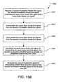
- FIG. 16Bis a flowchart of an exemplary method of the invention for the fourth feeder link architecture.
- U.S. Utility application Ser. No. 09/844,401describes a technique for transmitting digital information using multiple non-coherent carriers occupying overlapping portions of an RF band or channel. This technique is at its most efficient in a satellite transmission environment where each of the interfering carriers pass through a separate travelling wave tube amplifier (TWTA). Each amplifier (depending on the modulation type used for that carrier) can usually be operated at saturation, generally the most efficient use of such satellite-based TWTAs.
- TWTAtravelling wave tube amplifier
- Sophisticated ground receiversthat employ the technique described in U.S. Utility application Ser. No. 09/844,401 can demodulate each of these carriers where the frequency spectrum of one carrier can substantially or completely overlap the frequency spectrum used to transmit the other.
- the conventional technique for transmitting each carrier to its respective satellite TWTAis to transmit each carrier in its own dedicated (non-interfering) portion of feeder link bandwidth.
- the layered modulation techniqueuses interfering downlink carriers to gain considerable bandwidth efficiency, the amount of downlink bandwidth used is significantly less than that needed by the feeder links if this conventional technique is employed.
- the allocation of bandwidth to the feeder linkis equal to that allocated to the corresponding downlink. Without some scheme to get the carriers up to the satellite in the same amount of bandwidth used by the corresponding downlink, the downlink allocation could not be fully used.
- ITU-RInternational Telecommunication Union Radiocommunications Sector
- This inventiondescribes a number of techniques that can be employed to reduce the feeder link bandwidth requirement to no more than the bandwidth requirement of the downlink.
- FIG. 1is a diagram illustrating an overview of a single satellite video distribution system 100 .
- the video distribution system 100comprises a control center 102 in communication with an uplink center 104 via a ground or other link 114 and with a subscriber receiver station 110 via a public switched telephone network (PSTN) or other link 120 .
- the control center 102provides program material (e.g. video programs, audio programs and data) to the uplink center 104 and coordinates with the subscriber receiver stations 110 to offer, for example, pay-per-view (PPV) program services, including billing and associated decryption of video programs.
- program materiale.g. video programs, audio programs and data
- PSVpay-per-view
- the uplink center 104receives program material and program control information from the control center 102 , and using an uplink antenna 106 and transmitter 105 , transmits the program material and program control information to the satellite 108 via feeder link signal 116 .
- the satellite 108receives and processes this information, and transmits the video programs and control information to the subscriber receiver station 110 via downlink signal 118 using transmitter or transponder 107 .
- the subscriber receiving station 110receives this information using the outdoor unit (ODU) 112 , which includes a subscriber antenna and a low noise block converter (LNB).
- ODUoutdoor unit
- LNBlow noise block converter
- the subscriber receiving station antennais an 18-inch slightly oval-shaped Ku-band antenna.
- the slight oval shapeis due to the 22.5 degree offset feed of the LNB (low noise block converter) which is used to receive signals reflected from the subscriber antenna.
- the offset feedpositions the LNB out of the way so it does not block any surface area of the antenna minimizing attenuation of the incoming microwave signal.
- the video distribution system 100can comprise a plurality of satellites 108 in order to provide wider terrestrial coverage, to provide additional channels, or to provide additional bandwidth per channel.
- each satellitecomprises 16 transponders to receive and transmit program material and other control data from the uplink center 104 and provide it to the subscriber receiving stations 110 .
- two satellites 108 working togethercan receive and broadcast over 150 conventional (non-HDTV) audio and video channels via 32 transponders.
- the program material delivered to the subscriber 122is video (and audio) program material such as a movie
- the foregoing methodcan be used to deliver program material comprising purely audio information or other data as well.
- FIG. 2is a block diagram showing a typical uplink configuration for a single satellite 108 transponder, showing how video program material is uplinked to the satellite 108 by the control center 102 and the uplink center 104 .
- FIG. 2shows three video channels (which may be augmented respectively with one or more audio channels for high fidelity music, soundtrack information, or a secondary audio program for transmitting foreign languages), a data channel from a program guide subsystem 206 and computer data information from a computer data source 208 .
- Typical video channelsare provided by a program source 200 A- 200 C of video material (collectively referred to hereinafter as program source(s) 200 ).
- the data from each program source 200is provided to an encoder 202 A- 202 C (collectively referred to hereinafter as encoder(s) 202 ).
- encoder(s) 202Each of the encoders accepts a program time stamp (PTS) from the controller 216 .
- PTSprogram time stamp
- the PTSis a wrap-around binary time stamp that is used to assure that the video information is properly synchronized with the audio information after encoding and decoding.
- a PTS time stampis sent with each I-frame of the MPEG encoded data.
- each encoder 202is a second generation Motion Picture Experts Group (MPEG-2) encoder, but other decoders implementing other coding techniques can be used as well.
- the data channelcan be subjected to a similar compression scheme by an encoder (not shown), but such compression is usually either unnecessary, or performed by computer programs in the computer data source (for example, photographic data is typically compressed into *.TIF files or *.JPG files before transmission).
- the signalsare converted into data packets by a packetizer 204 A- 204 F (collectively referred to hereinafter as packetizer(s) 204 ) associated with each program source 200 .
- the output data packetsare assembled using a reference from the system clock 214 (SCR), and from the conditional access manager 210 , which provides the service channel identifier (SCID) to the packetizers 204 for use in generating the data packets. These data packets are then multiplexed into serial data and transmitted.
- SCRsystem clock 214
- SCIDservice channel identifier
- FIG. 3Ais a diagram of a representative data stream.
- the first packet 302comprises information from video channel 1 (data coming from, for example, the first video program source 200 A).
- the next packet 304comprises computer data information that was obtained, for example from the computer data source 208 .
- the next packet 306comprises information from video channel 5 (from one of the video program sources 200 ).
- the next packet 308comprises program guide information such as the information provided by the program guide subsystem 206 .
- null packets 310 created by the null packet module 212may be inserted into the data stream as desired followed by further data packets 312 , 314 , 316 from the program sources 200 .
- the data streamtherefore comprises a series of packets ( 302 - 316 ) from any one of the data sources (e.g. program sources 200 , program guide subsystem 206 , computer data source 208 ) in an order determined by the controller 216 .
- the data streamis encrypted by the encryption module 218 , modulated by the modulator 220 (typically using a QPSK modulation scheme), and provided to the transmitter 105 , which broadcasts the modulated data stream on a frequency bandwidth to the satellite via the antenna 106 .
- the receiver 500 at the receiver station 110receives these signals, and using the SCID, reassembles the packets to regenerate the program material for each of the channels.
- FIG. 3Bis a diagram of a data packet.
- Each data packet(e.g. 302 - 316 ) is 147 bytes long, and comprises a number of packet segments.
- the first packet segment 320comprises two bytes of information containing the SCID and flags.
- the SCIDis a unique 12-bit number that uniquely identifies the data packet's data channel.
- the flagsinclude 4 bits that are used to control other features.
- the second packet segment 322is made up of a 4-bit packet type indicator and a 4-bit continuity counter.
- the packet typegenerally identifies the packet as one of the four data types (video, audio, data, or null). When combined with the SCID, the packet type determines how the data packet will be used.
- the continuity counterincrements once for each packet type and SCID.
- the next packet segment 324comprises 127 bytes of payload data, which in the cases of packets 302 or 306 is a portion of the video program provided by the video program source 200 .
- FIG. 4is a block diagram showing one embodiment of the modulator 220 .
- the modulator 220optionally comprises a forward error correction (FEC) encoder 404 which accepts the first signal symbols 402 and adds redundant information that are used to reduce transmission errors.
- the coded symbols 405are modulated by modulator 406 according to a first carrier 408 to produce an upper layer modulated signal 410 .
- Second symbols 420are likewise provided to an optional second FEC encoder 422 to produce coded second symbols 422 .
- the coded second symbols 422are provided to a second modulator 414 , which modulates the coded second signals according to a second carrier 416 to produce a lower layer modulated signal 418 .
- the resulting signalsare then transmitted by one or more transmitters 420 , 422 .
- the upper layer modulated signal 410 and the lower layer modulated signal 418are therefore uncorrelated, and the frequency range used to transmit each layer can substantially or completely overlap the frequency spectrum used to transmit the other.
- the frequency spectrum f 1 ⁇ f 3 432 of the upper layer signal 410may overlap the frequency spectrum f 2 a ⁇ f 4 434 of the lower layer signal 418 in frequency band f 2 ⁇ f 3 436 .
- the upper layer signal 410must be a sufficiently greater amplitude signal than the lower layer signal 418 , in order to maintain the signal constellations shown in FIG. 6 and FIG. 7 .
- the modulator 220may also employ pulse shaping techniques (illustrated by pulse p(t) 430 ) to account for the limited channel bandwidth. Although FIG. 4 illustrates the same pulse shaping p(t) 430 being applied to both layers, different pulse shaping can be applied to each layer as well.
- FIG. 5is a block diagram of an integrated receiver/decoder (IRD) 500 (also hereinafter alternatively referred to as receiver 500 ).
- the receiver 500comprises a tuner/demodulator 504 communicatively coupled to an ODU 112 having one or more low noise blocks (LNBs) 502 .
- LNBslow noise blocks
- the LNB 502converts the 12.2- to 12.7 GHz downlink 118 signal from the satellites 108 to, e.g., a 950-1450 MHz signal required by the IRD's 500 tuner/demodulator 504 .
- the LNB 502may provide either a dual or a single output.
- the single-output LNB 502has only one RF connector, while the dual output LNB 502 has two RF output connectors and can be used to feed a second tuner 504 , a second receiver 500 , or some other form of distribution system.
- the tuner/demodulator 504isolates a single, digitally modulated 24 MHz transponder signal, and converts the modulated data to a digital data stream.
- the digital data streamis then supplied to a forward error correction (FEC) decoder 506 .
- FECforward error correction
- the error-corrected datamay be fed from the FEC decoder module 506 to the transport module 508 via an 8-bit parallel interface.
- the transport module 508performs many of the data processing functions performed by the IRD 500 .
- the transport module 508processes data received from the FEC decoder module 506 and provides the processed data to the video MPEG decoder 514 and the audio MPEG decoder 517 .
- the transport moduleemploys system RAM 528 to process the data.
- the transport module 508 , video MPEG decoder 514 and audio MPEG decoder 517are all implemented on integrated circuits. This design promotes both space and power efficiency, and increases the security of the functions performed within the transport module 508 .
- the transport module 508also provides a passage for communications between the microcontroller 510 and the video and audio MPEG decoders 514 , 517 .
- the transport modulealso works with the conditional access module (CAM) 512 to determine whether the receiver 500 is permitted to access certain program material. Data from the transport module 508 can also be supplied to external communication module 526 .
- CAMconditional access module
- the CAM 512functions in association with other elements to decode an encrypted signal from the transport module 508 .
- the CAM 512may also be used for tracking and billing these services.
- the CAM 512is a removable smart card, having contacts cooperatively interacting with contacts in the IRD 500 to pass information.
- the IRD 500and specifically the transport module 508 provides a clock signal to the CAM 512 .
- Video datais processed by the MPEG video decoder 514 .
- the MPEG video decoder 514decodes the compressed video data and sends it to an encoder or video processor 516 , which converts the digital video information received from the video MPEG module 514 into an output signal usable by a display or other output device.
- processor 516may comprise a National TV Standards Committee (NTSC) or Advanced Television Systems Committee (ATSC) encoder.
- NTSCNational TV Standards Committee
- ATSCAdvanced Television Systems Committee
- S-Video and ordinary video (NTSC or ATSC) signalsare provided.
- Other outputsmay also be utilized, and are advantageous if high definition programming is processed.
- Audio datais likewise decoded by the MPEG audio decoder 517 .
- the decoded audio datamay then be sent to a digital to analog (D/A) converter 518 .
- the D/A converter 518is a dual D/A converter, one for the right and left channels. If desired, additional channels can be added for use in surround sound processing or secondary audio programs (SAPs).
- SAPssecondary audio programs
- the dual D/A converter 518itself separates the left and right channel information, as well as any additional channel information.
- Other audio formatsmay similarly be supported. For example, other audio formats such as multi-channel DOLBY DIGITAL AC-3 may be supported.
- the microcontroller 510receives and processes command signals from a remote control, an IRD 500 keyboard interface, and/or other suitable input device 524 .
- the microcontroller 510receives commands for performing its operations from a processor programming memory, which permanently stores such instructions for performing such commands.
- the processor programming memorymay comprise a read only memory (ROM) 538 , an electrically erasable programmable read only memory (EEPROM) 522 or, similar memory device.
- the microcontroller 510also controls the other digital devices of the IRD 500 via address and data lines (denoted “A” and “D” respectively, in FIG. 5 ).
- the modem 540connects to the customer's phone line via the PSTN port 120 . It calls, e.g. the program provider, and transmits the customer's purchase information for billing purposes, and/or other information.
- the modem 540is controlled by the microprocessor 510 .
- the modem 540can output data to other I/O port types including standard parallel and serial computer I/O ports.
- the present inventionalso comprises a local storage unit such as the video storage device 532 for storing video and/or audio data obtained from the transport module 508 .
- Video storage device 532can be a hard disk drive, a read/writable compact disc of DVD, a solid state RAM, or any other suitable storage medium.
- the video storage device 532is a hard disk drive with specialized parallel read/write capability so that data may be read from the video storage device 532 and written to the device 532 at the same time. To accomplish this feat, additional buffer memory accessible by the video storage 532 or its controller may be used.
- a video storage processor 530can be used to manage the storage and retrieval of the video data from the video storage device 532 .
- the video storage processor 530may also comprise memory for buffering data passing into and out of the video storage device 532 .
- a plurality of video storage devices 532can be used.
- the microcontroller 510can also perform the operations required to store and or retrieve video and other data in the video storage device 532 .
- the video processing module 516 inputcan be directly supplied as a video output to a viewing device such as a video or computer monitor.
- the video and/or audio outputscan be supplied to an RF modulator 534 to produce an RF output and/or 8 vestigal side band (VSB) suitable as an input signal to a conventional television tuner. This allows the receiver 500 to operate with televisions without a video output.
- a viewing devicesuch as a video or computer monitor.
- the video and/or audio outputscan be supplied to an RF modulator 534 to produce an RF output and/or 8 vestigal side band (VSB) suitable as an input signal to a conventional television tuner.
- VSBvestigal side band
- Each of the satellites 108comprises a transponder, which accepts program information from the uplink center 104 , and relays this information to the subscriber receiving station 110 .
- Known multiplexing techniquesare used so that multiple channels can be provided to the user. These multiplexing techniques include, by way of example, various statistical or other time domain multiplexing techniques and polarization multiplexing.
- a single transponder operating at a single frequency bandcarries a plurality of channels identified by respective service channel identification (SCID).
- SCIDservice channel identification
- the IRD 500also receives and stores a program guide in a memory available to the microcontroller 510 .
- the program guideis received in one or more data packets in the data stream from the satellite 108 .
- the program guidecan be accessed and searched by the execution of suitable operation steps implemented by the microcontroller 510 and stored in the processor ROM 538 .
- the program guidemay include data to map viewer channel numbers to satellite transponders and service channel identifications (SCIDs), and also provide TV program listing information to the subscriber 122 identifying program events.
- SCIDsservice channel identifications
- the functionality implemented in the IRD 500 depicted in FIG. 5can be implemented by one or more hardware modules, one or more software modules defining instructions performed by a processor, or a combination of both.
- the present inventionprovides for the modulation of signals at different power levels and advantageously for the signals to be non-coherent from each layer.
- independent modulation and coding of the signalsmay be performed.
- Backwards compatibility with legacy receivers, such as a quadrature phase shift keying (QPSK) receiveris enabled and new services are provided to new receivers.
- QPSKquadrature phase shift keying
- a typical new receiver of the present inventionuses two demodulators and one remodulator (which can be combined in one or more processors) as will be described in detail hereafter.
- the legacy QPSK signalis boosted in power to a higher transmission (and reception) level.
- the legacy receiverwill not be able to distinguish the new lower layer signal, from additive white Gaussian noise, and thus operates in the usual manner.
- the optimum selection of the layer power levelsis based on accommodating the legacy equipment, as well as the desired new throughput and services.
- the new lower layer signalis provided with a sufficient carrier to thermal noise ratio to function properly.
- the new lower layer signal and the boosted legacy signalare non-coherent with respect to each other. Therefore, the new lower layer signal can be implemented from a different TWTA and even from a different satellite.
- the new lower layer signal formatis also independent of the legacy format, e.g., it may be QPSK or 8PSK, using the conventional concatenated FEC code or using a new Turbo code.
- the lower layer signalmay even be an analog signal.
- the combined layered signalis demodulated and decoded by first demodulating the upper layer to remove the upper carrier.
- the stabilized layered signalmay then have the upper layer FEC decoded and the output upper layer symbols communicated to the upper layer transport.
- the upper layer symbolsare also employed in a remodulator, to generate an idealized upper layer signal.
- the idealized upper layer signalis then subtracted from the stable layered signal to reveal the lower layer signal.
- the lower layer signalis then demodulated and FEC decoded and communicated to the lower layer transport.
- Signals, systems and methods using the present inventionmay be used to supplement a pre-existing transmission compatible with legacy receiving hardware in a backwards-compatible application or as part of a preplanned layered modulation architecture providing one or more additional layers at a present or at a later date.
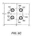
- FIGS. 6A-6Cillustrate the basic relationship of signal layers in a received layered modulation transmission.
- FIG. 6Aillustrates an upper layer signal constellation 600 of a transmission signal showing the signal points or symbols 602 .
- FIG. 6Billustrates the lower layer signal constellation of symbols 604 over the upper layer signal constellation 600 where the layers are coherent (or synchronized).
- FIG. 6Cillustrates a lower layer signal 606 of a second transmission layer over the upper layer constellation where the layers are non-coherent.
- the lower layer 606rotates about the upper layer constellation 602 due to the relative modulating frequencies of the two layers in a non-coherent transmission. Both the upper and lower layers rotate about the origin due to the first layer modulation frequency as described by path 608 .
- FIGS. 7A-7Care diagrams illustrating a non-coherent relationship between a lower transmission layer over the upper transmission layer after upper layer demodulation.
- FIG. 7Ashows the constellation 700 before the first carrier recovery loop (CRL) of the upper layer, The constellation rings 702 rotate around the large radius circle indicated by the dashed line.
- FIG. 7Bshows the constellation 704 after CRL of the upper layer where the rotation of the constellation rings 702 is stopped.
- the constellation rings 702are the signal points of the lower layer around the nodes 602 of the upper layer.
- FIG. 7Cdepicts a phase distribution of the received signal with respect to nodes 602 .
- Relative modulating frequencies of the non-coherent upper and lower layer signalscause the lower layer constellation to rotate around the nodes 602 of the upper layer constellation to form rings 702 . After the lower layer CRL this rotation is eliminated and the nodes of the lower layer are revealed (as shown in FIG. 6B ).
- the radius of the lower layer constellation rings 702is indicative of the lower layer power level.
- the thickness of the rings 702is indicative of the carrier to noise ratio (CNR) of the lower layer.
- CNRcarrier to noise ratio
- the lower layermay be used to transmit distinct digital or analog signals.
- FIG. 8Ais a diagram showing a system for transmitting and receiving layered modulation signals.
- Separate transponders 107 A, 107 B(which include TWTAs to amplify the signals), as may be located on any suitable platform, such as satellites 108 A, 108 B, are used to non-coherently transmit different layers of a signal of the present invention.
- One or more feeder link signals 116are typically transmitted to each satellite 108 A, 108 B from one or more uplink centers 104 with one or more transmitters 105 via an antenna 106 .
- the present inventiondescribes particular feeder link architectures for use in a layered modulation system.
- FIG. 8Bis a diagram illustrating an exemplary satellite transponder 107 for receiving and transmitting layered modulation signals on a satellite 108 .
- the feeder link signal 116is received by the satellite 108 and passed through an input multiplexer (IMUX) 814 . Following this the signal is amplified with one or more a traveling wave tube amplifiers (TWTAs) 816 and then through an output multiplexer (OMUX) 818 before the downlink signal 118 is transmitted to the receivers 802 , 500 .
- TWTA 816 blockcan be multiple TWTAs in a power combiner, particularly in the case of the upper layer signal.
- Embodiments of the present inventionrelate to specific architectures of the feeder link and satellite transponders 107 as detailed hereafter in section 5 .
- the layered signals 808 A, 808 B(e.g. multiple downlink signals 118 ) are received at receiver antennas 812 A, 812 B, such as satellite dishes, each with a low noise block (LNB) 810 A, 810 B where they are then coupled to integrated receiver/decoders (IRDs) 500 , 802 .
- LNBlow noise block
- first satellite 108 A and transponder 107 Acan transmit an upper layer legacy signal 808 A
- second satellite 108 B and transponder 107 Bcan transmit a lower layer signal 808 B.
- both signals 808 A, 808 Barrive at each antenna 812 A, 812 B and LNB 810 A, 810 B, only the layer modulation IRD 802 is capable of decoding both signals 808 A, 808 B.
- the legacy receiver 500is only capable of decoding the upper layer legacy signal 808 A; the lower layer signal 808 B appears only as noise to the legacy receiver 500 .
- any composite signal, including new additional signal layerswill be backwards compatible with legacy receivers 500 , which will disregard the new signal layers.
- the combined signal and noise level for the lower layermust be at or below the allowed noise floor for the upper layer at the particular receiver antenna 812 A, 812 B.
- Layered modulation applicationsinclude backwards compatible and non-backwards compatible applications.
- “Backwards compatible”in this sense, describes systems in which legacy receivers 500 are not rendered obsolete by the additional signal layer(s). Instead, even if the legacy receivers 500 are incapable of decoding the additional signal layer(s), they are capable of receiving the layered modulated signal and decoding the original signal layer. In these applications, the pre-existing system architecture is accommodated by the architecture of the additional signal layers.
- “Non-backwards compatible”describes a system architecture which makes use of layered modulation, but the modulation scheme employed is such that pre-existing equipment is incapable of receiving and decoding the information on additional signal layer(s).
- the pre-existing legacy IRDs 500decode and make use of data only from the layer (or layers) they were designed to receive, unaffected by the additional layers.
- the legacy signalsmay be modified to optimally implement the new layers.
- the present inventionmay be applied to existing direct satellite services which are broadcast to individual users in order to enable additional features and services with new receivers without adversely affecting legacy receivers and without requiring additional signal frequency.
- FIG. 9is a block diagram depicting one embodiment of an enhanced IRD 802 capable of receiving layered modulation signals.
- the IRDincludes many similar components as that of the legacy IRD 500 of FIG. 5 .
- the enhanced IRD 802includes a feedback path 902 in which the FEC decoded symbols are fed back to an enhanced modified tuner/demodulator 904 and transport module 908 for decoding both signal layers as detailed hereafter.
- FIG. 10Ais a block diagram of one embodiment of the enhanced tuner/modulator 904 and FEC encoder 506 .
- FIG. 10Adepicts reception where layer subtraction is performed on a signal where the upper layer carrier has already been demodulated.
- the upper layer of the received combined signal 1016 from the LNB 502which may contain legacy modulation format, is provided to and processed by an upper layer demodulator 1004 to produce the stable demodulated signal 1020 .
- the demodulated signal 1020is communicatively coupled to a FEC decoder 1002 which decodes the upper layer to produce the upper layer symbols which are output to an upper layer transport module 908 .
- the upper layer symbolsare also used to generate an idealized upper layer signal.
- the upper layer symbolsmay be produced from the decoder 1002 after Viterbi decode (BER ⁇ 10 ⁇ 3 or so) or after Reed-Solomon (RS) decode (BER ⁇ 10 ⁇ 9 or so), in typical decoding operations known to those skilled in the art.
- the upper layer symbolsare provided via feedback path 902 from the upper layer decoder 1002 to a re-encoder/remodulator 1006 which effectively produces an idealized upper layer signal.
- the idealized upper level signalis subtracted from the demodulated upper layer signal 1020 .
- the modulated signalmay have been distorted, for example, by traveling wave tube amplifier (TWTA) non-linearity or other non-linear or linear distortions in the transmission channel.
- TWTAtraveling wave tube amplifier
- the distortion effectsare estimated from the received signal after the fact or from TWTA characteristics which may be downloaded into the IRD in AM-AM and/or AM-PM maps 1014 , used to eliminate the distortion using non-linear distortion map module 1018 .
- a subtractor 1012then subtracts the idealized upper layer signal from the stable demodulated signal 1020 . This leaves the lower-power second layer signal.
- the subtractor 1012may include a buffer or delay function to retain the stable demodulated signal 1020 while the idealized upper layer signal is being constructed.
- the second layer signalis demodulated by the lower level demodulator 1010 and FEC decoded by decoder 1008 according to its signal format to produce the lower layer symbols, which are provided to the transport module 908 .
- FIG. 10Bdepicts another embodiment wherein layer subtraction is performed on the received layered signal (prior to upper layer demodulation).
- the upper layer demodulator 1004produces the upper carrier signal 1022 (as well as the stable demodulated signal output 1020 ).
- An upper carrier signal 1022is provided to the re-encoder/remodulator 1006 .
- the re-encoder/remodulator 1006provides the re-encoded and remodulated signal to the non-linear distortion mapper 1018 which effectively produces an idealized upper layer signal.
- the idealized upper layer signalincludes the upper layer carrier for subtraction from the received combined signal 808 A, 808 B.
- M Uis the magnitude of the upper layer QPSK signal
- M Lis the magnitude of the lower layer QPSK signal
- M L ⁇ M U.
- the signal frequencies and phase for the upper and lower layer signalsare respectively ⁇ U , ⁇ U and ⁇ U , ⁇ U .
- the symbol timing misalignment between the upper and lower layersis ⁇ T m .
- p(t ⁇ mT)represents the time shifted version of the pulse shaping filter p(t) 414 employed in signal modulation.
- QPSK symbols S Um and S Lmare elements of
- the upper layer decoder 402disregards the M L component of the s′ UL (t).
- any distortion effectssuch as TWTA nonlinearity effects are estimated for signal subtraction.
- the upper and lower layer frequenciesare substantially equal. Significant improvements in system efficiency can be obtained by using a frequency offset between layers.
- two-layered backward compatible modulation with QPSKdoubles a current 6/7 rate capacity by adding a TWTA approximately 6.2 dB above an existing TWTA power.
- New QPSK signalsmay be transmitted from a separate transmitter, from a different satellite for example.
- TWTAslinear travelling wave tube amplifiers
- 16QAMphase error penalty
- the relationship between the individual modulation layerscan be structured to facilitate backward compatible applications.
- a new layer structurecan be designed to optimize the combined efficiency and/or performance of the layered modulation system.
- FIG. 11Adepicts the relative power levels 1100 of example embodiments of the present invention without taking into account the effects of rain. Accommodation of rain fade effects comes through the inclusion of clear sky margin in the calculation of transmit power levels, and this is treated in a later section.
- FIG. 11Ais not a scale drawing.
- This embodimentdoubles the pre-existing rate 6/7 capacity by using a TWTA whose power level is 6.2 dB above a pre-existing (legacy) TWTA, and a second TWTA whose power level is 2 dB below that of a pre-existing (legacy) TWTA.
- This embodimentuses upper and lower QPSK layers which are non-coherent.
- An FEC code rate of 6/7is also used for both layers.
- the signal of the legacy QPSK signal 1102is used to generate the upper layer 1104 and a new QPSK layer is the lower layer 1110 .
- the legacy QPSK signal 1102has a threshold CNR (i.e., the carrier to noise ratio required to achieve acceptable performance) of approximately 7 dB.
- the new lower QPSK layer 1110has a threshold CNR of approximately 5 dB.
- the lower QPSK layer transmit power level 1110is first set so that the received lower layer power is 5 dB above the reference thermal noise power level 1108 . Both the thermal noise and the lower layer signal will appear as noise to the upper layer legacy QPSK signal, and this combined noise power must be taken into account when setting the upper layer transmit power level.
- the combined power of these two noise sources 1106is 6.2 dB above the reference thermal noise floor 1108 .
- the legacy QPSK signalmust then be boosted in power by approximately 6.2 dB above the legacy signal power level 1102 bringing the new power level to approximately 13.2 dB as the upper layer 1104 . In this way the combined lower layer signal power and thermal noise power is kept at or below the tolerable noise floor 1106 of the upper layer. It should be noted that the invention may be extended to multiple layers with mixed modulations, coding and code rates.
- an FEC code rate of 2 ⁇ 3may be used for both the upper and lower layers 1104 , 1110 .
- the threshold CNR of the legacy QPSK signal 1102(with an FEC code rate of 2 ⁇ 3) is approximately 5.8 dB.
- the legacy signal 1102is boosted by approximately 5.3 dB to approximately 11.1 dB (4.1 dB above the legacy QPSK signal 1102 with an FEC code rate of 2 ⁇ 3) to form the upper QPSK layer 1104 .
- the new lower QPSK layer 1110has a threshold CNR of approximately 3.8 dB.
- the total signal and noise of the lower layer 1110is kept at or below approximately 5.3 dB, the tolerable noise floor 1106 of the upper QPSK layer. In this case, the total capacity is 1.55 times that the legacy signal 1102 .
- the code rates between the upper and lower layers 1104 , 1110may be mixed.
- the legacy QPSK signal 502may be boosted by approximately 5.3 dB to approximately 12.3 dB with the FEC code rate unchanged at 6/7 to create the upper QPSK layer 1104 .
- the new lower QPSK layer 1110may use an FEC code rate of 2 ⁇ 3 with a threshold CNR of approximately 3.8 dB. In this case, the total capacity is 1.78 times that of the legacy signal 1102 .
- two QPSK layers 1104 , 1110are used each at a code rate of 2 ⁇ 3.
- the upper QPSK layer 504has a CNR of approximately 4.1 dB above its noise floor 1106 and the lower QPSK layer 1110 also has a CNR of approximately 4.1 dB.
- the total code and noise level of the lower QPSK layer 1110is approximately 5.5 dB.
- the total CNR for the upper QPSK signal 1104is approximately 9.4 dB, merely 2.4 dB above the legacy QPSK signal rate 6/7.
- the capacityis approximately 1.74 compared to the legacy rate 6/7.
- FIG. 11Bdepicts the relative power levels of an alternate embodiment wherein both the upper and lower layers 1104 , 1110 are below the legacy signal level 1102 .
- the two QPSK layers 1104 , 1110use a code rate of 1 ⁇ 2.
- the upper QPSK layer 1104is approximately 2.00 dB above its noise floor 1106 of approximately 4.1 dB.
- the lower QPSK layerhas a CNR of approximately 2.0 dB and a total code and noise level at or below 4.1 dB.
- the capacity of this embodimentis approximately 1.31 compared to the legacy rate 6/7.
- FIG. 12illustrates an exemplary computer system 1200 that could be used to implement selected modules and/or functions of the present invention.
- the computer 1202comprises a processor 1204 and a memory 1206 , such as random access memory (RAM).
- the computer 1202is operatively coupled to a display 1222 , which presents images such as windows to the user on a graphical user interface 1218 B.
- the computer 1202may be coupled to other devices, such as a keyboard 1214 , a mouse device 1216 , a printer, etc.
- a keyboard 1214a keyboard 1214
- a mouse device 1216a printer, etc.
- printera printer
- the computer 1202operates under control of an operating system 1208 stored in the memory 1206 , and interfaces with the user to accept inputs and commands and to present results through a graphical user interface (GUI) module 1218 A.
- GUIgraphical user interface
- the instructions performing the GUI functionscan be resident or distributed in the operating system 1208 , the computer program 1210 , or implemented with special purpose memory and processors.
- the computer 1202also implements a compiler 1212 which allows an application program 1210 written in a programming language such as COBOL, C++, FORTRAN, or other language to be translated into processor 1204 readable code.
- the application 1210accesses and manipulates data stored in the memory 1206 of the computer 1202 using the relationships and logic that was generated using the compiler 1212 .
- the computer 1202also optionally comprises an external communication device such as a modem, satellite link, Ethernet card, or other device for communicating with other computers.
- instructions implementing the operating system 1208 , the computer program 1210 , and the compiler 1212are tangibly embodied in a computer-readable medium, e.g., data storage device 1220 , which could include one or more fixed or removable data storage devices, such as a zip drive, floppy disc drive 1224 , hard drive, CD-ROM drive, tape drive, etc.
- the operating system 1208 and the computer program 1210are comprised of instructions which, when read and executed by the computer 1202 , causes the computer 1202 to perform the steps necessary to implement and/or use the present invention.
- Computer program 1210 and/or operating instructionsmay also be tangibly embodied in memory 1206 and/or data communications devices 1230 , thereby making a computer program product or article of manufacture according to the invention.
- article of manufacture“program storage device” and “computer program product” as used herein are intended to encompass a computer program accessible from any computer readable device or media.
- feeder link architecturescomprise feeder link architectures represented by the examples shown in FIGS. 13A , 14 A, 15 A and 16 A hereafter. As detailed below, these embodiments may include alterations and/or elaboration to the basic modulator 220 and transponder 108 of the exemplary system of FIGS. 4 and 8B previously described.
- the feeder link architectures of the present inventionare not limited to applications where the upper layer signal is a legacy signal.
- the upper layer signal 808 Acan be a legacy signal. Accordingly, a legacy IRD 500 can demodulate the upper layer signal 808 A directly from the layered signal. The lower layer signal 808 B is ignored as noise in the legacy IRD 500 . Alternately, in a layered modulation IRD 802 , both the upper layer and lower layer signals 808 A, 808 B are demodulated.
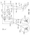
- FIG. 13Aillustrates a first feeder link system 1300 for a layered modulation signal.
- the uplink signals 116comprise two distinct feeder link signals 1302 A, 1302 B.
- Feeder link spot beam antennas 1304 A, 1304 Bcan be employed on the satellite 108 to reuse feeder link spectrum in order to not exceed bandwidth of the layered modulation on the downlink.
- the feeder link system 1300includes a first feeder link antenna 1306 A located within a first coverage area 1308 A of the first feeder link spot beam antenna 1304 A.
- a second feeder link antenna 1304 Bis located within a second coverage area 1308 B of the second feeder link spot beam antenna 1304 B.
- the first and second coverage areas 1308 A, 1308 Bare distinct from one another and do not overlap.
- These signals 1302 A, 1302 Bare formed on board the satellite 108 by each feeder link spot beam antenna 1304 A, 1304 B.
- the first feeder link antenna 1306 Atransmits the first feeder link signal 1302 A at a first frequency.
- the first feeder link signal 1302 Acomprises the information that will be carried on the upper layer downlink signal 808 A.
- the second feeder link antenna 1306 Btransmits the second feeder link signal 1302 B at a second frequency.
- This feeder link signal 1302 Bcomprises the information that will be carried on the lower layer downlink signal 808 B.
- the two feeder link frequenciesare in substantially the same frequency band, the use of spot beam antennas 1304 A, 1304 B with distinct coverage areas 1308 A, 1308 B prevents the first and second feeder link signals 1302 A, 1302 B from interfering.
- This feeder link system 1300requires that the two feeder link signals 1302 A, 1302 B have sufficient isolation between them. This can be more difficult to achieve when applied to smaller regions (smaller countries where there may be insufficient space for the formation of two feeder link spot beams).
- the transponders 107 A, 107 Beach receive one of feeder link signals 1302 A, 1302 B.
- the downlink layered signals 808 A, 808 Bare formed by appropriate filtering, translation of each layer to its assigned downlink frequency, and adjustment of the layer power level in the respective receivers 1310 A, 1310 B.
- the assigned downlink frequenciesare understood to result in either partial or complete signal bandwidth overlap between the layers.
- each layered signal 808 A, 808 Bis sent to the respective downlink amplifier 1312 A, 1312 B (which include one or more TWTAs that can be arranged in a power combiner, particularly for the upper layer signal 808 A).
- separate satellite antennas 1314 A, 1314 Bare used to transmit the upper layer downlink signal 808 A and the lower layer downlink signal 808 B, respectively, to substantially the same coverage area.
- the upper layer downlink signal 808 A and the lower layer downlink signal 808 Bare combined in space to form the layered modulation signal.
- the user's IRD 500 , 802receives the two overlapping signals through the technique described in Utility application Ser. No. 09/844,401, is able to demodulate one or both of each layered signal 808 A, 808 B.
- the amount of feeder link spectrum required to support transmission of the layered modulation downlink signal 808is no more than the required downlink spectrum.
- This feeder link system 1300retains the advantage of an asynchronous relationship between the downlink layered signals 808 A, 808 B and also retains the advantage of separate saturated satellite downlink amplifiers 1312 A, 1312 B for each layer.
- the asynchronous (non-coherent) relationship between the two layered signals 808 A, 808 Ballows them to operate at different symbol rates and to use independent modulation formats and to use independent forward error correction techniques.
- the use of separate saturated downlink amplifiers 1312 A, 1312 Ballows the upper layer amplifier 1312 A to be significantly lower in saturated output power than would otherwise be required.
- the two transponders 107 A, 10713 of the feeder link system 1300can be on a common satellite 108 as shown or exist on different satellites 108 A, 108 B, although level control of the signals is more easily achieved if the transponders 107 A, 107 B are on the same satellite 108 .
- FIG. 13Bis a flowchart of an exemplary method 1340 of the invention for the first feeder link architecture.
- a first feeder link signalis received using a first feeder link spot beam antenna for a first satellite transponder wherein the first feeder link spot beam antenna transmits from a first coverage area.
- the first satellite transponderis for transmitting an upper layer signal of a layered modulation signal to at least one integrated receiver/decoder (IRD).
- a second feeder link signalis received using a second feeder link spot beam antenna for a second satellite transponder wherein the second feeder link spot beam antenna transmits from a second coverage area distinct from the first coverage area and the second feeder link signal reuses a frequency spectrum of the first feeder link signal.
- the second satellite transponderis for transmitting a lower layer signal of the layered modulation signal to the at least one IRD.
- the method 1340can be further modified consistent with the feeder link system 1300 described above.
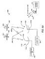
- FIG. 14Aillustrates a second feeder link system 1400 for a layered modulation signal.
- This system 1400employs feeder link signal discrimination in order to reuse feeder link spectrum to support layered modulation in the downlink signal 808 A, 808 B.
- the downlink layered signals 808 A, 808 Bmust be generated from two satellites 108 A, 108 B so that an orbital separation 1408 provides adequate feeder link signal discrimination.
- the two satellites 108 A, 108 Bcan be in geosynchronous orbit, separated by an orbital separation 1408 of nominally 0.4 degrees of longitude.
- Very large feeder link antennas 1406 A, 1406 Bare used to provide very narrow and highly focused beams for transmission to the satellites 108 A, 108 B.
- the large antennas 1406 A, 1406 Bare typical of conventional feeder antennas, e.g. in the range of approximately 7 to 10 meters in diameter for the 17 Ghz feeder link band.
- Each of the feeder link signals 1402 A, 1402 Bcan be focused on the receive antenna 1404 A, 1404 B of its respective satellite 108 A, 108 B as shown and yet the orbital separation 1408 provides adequate isolation from the feeder link signal 1402 A, 1402 B to the other satellite 108 A, 108 B to allow frequency reuse. This allows both feeder link antennas 1406 A, 1406 B to transmit in the same portion of the frequency band and not interfere with one another.
- Embodiments of the present inventioncan apply the techniques employed in U.S. Utility application Ser. No. 10/305,490 related to feeder link antenna beam discrimination to implement layered modulation downlink signals 808 A, 808 B.
- a first feeder link antenna 1406 Atransmits a first feeder link signal 1402 A at a first frequency to a first transponder 107 A of a first satellite 108 A.
- a second feeder link antenna 1406 Btransmits a second feeder link signal 1402 B at a second frequency to a second transponder 107 B of a second satellite 108 B.
- these two feeder link frequenciesare considered to be very close together such that the one feeder link signal, e.g. 1402 A is in the same portion of the feeder link frequency band that is occupied by the other feeder link signal, e.g. 1402 B.
- the orbital separation 1408is adequate to allow reuse in the feeder link frequency band.
- Each satellite receiver 1410 A, 1410 Breceives one feeder link signal 1402 A, 1492 B.
- the downlink layered signals 808 A, 808 Bare formed by appropriate filtering, translation of each layer to its assigned downlink frequency and adjustment of the layer power level in the respective receivers 1410 A, 1410 B.
- the assigned downlink frequenciesare understood to result in either partial or complete signal bandwidth overlap between the layers.
- each layered signal 808 A, 808 Bis sent to the respective downlink amplifier 1412 A, 1412 B (which include one or more TWTAs that can be arranged in a power combiner, particularly for the upper layer signal 808 A).
- separate satellite antennas 1414 A, 1414 Bare used to transmit the upper layer downlink signal 808 A and the lower layer downlink signal 808 B, respectively, to substantially the same coverage area.
- the upper layer downlink signal 808 A and the lower layer downlink signal 808 Bare combined in space to form the layered modulation signal 808 .
- the user's IRD 500 , 802receives the two overlapping signals through the technique described in Utility application Ser. No. 09/844,401, is able to demodulate one or both of each layered signal 808 A, 808 B.
- the amount of feeder link spectrum required to support transmission of the layered modulation downlink signal 808is no more than the required downlink spectrum.
- this feeder link system 1400retains the advantage of an asynchronous (non-coherent) relationship between the layered signals 808 A, 808 B, and retains the advantage of separate saturated satellite amplifiers 1412 A, 1412 B for each downlink signal 808 A, 808 B.
- the non-coherent relationship between the two layered signals 808 A, 808 Ballows them to operate at different symbol rates and to use independent modulation formats and to use independent forward error correction techniques.
- the use of separate saturated downlink amplifiers 1412 A, 1412 Ballows the upper layer amplifier 1412 A to be significantly lower in saturated output power than would otherwise be required. This significantly reduces the linearity requirements on these amplifiers 1412 A, 1412 B.
- this feeder link system 1400requires the presence of two separate satellites 107 A, 107 B to cleanly receive the feeder link signals 1402 A, 1402 B and produce the layered modulation downlink signal 808 , conventional feeder link antennas 1406 A, 1406 B can be used without spot beam receive antennas on the satellites 108 A, 108 B.
- FIG. 14Bis a flowchart of an exemplary method 1440 of the invention for the first feeder link architecture.
- a first feeder link signal for a first satellite transponder on a first satelliteis received.
- the first satellite transponderis for transmitting an upper layer signal of a layered modulation signal to at least one integrated receiver/decoder (IRD).
- a second feeder link signal for a second satellite transponder on a second satelliteis received wherein the second feeder link signal reuses a frequency band of the first feeder link signal and the first satellite and the second satellite have an orbital separation sufficient to allow reuse of the frequency band.
- the second satellite transponderis for transmitting a lower layer signal of the layered modulation signal to the at least one IRD.
- the method 1440can be further modified consistent with the feeder link system 1400 described above.
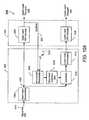
- FIG. 15Aillustrates a third feeder link system 1500 for a layered modulation signal.
- a feeder link layered modulation signalcomprising an upper layer feeder link signal 1502 A and a lower layer feeder link signal 1502 B is generated at the feeder link station (uplink center 104 ) and then transmitted up to the satellite 108 .
- Combining of the two feeder link signals 1502 A, 1502 Bcan be performed in space as shown in FIG. 15A , with a separate modulator, upconverter and high power amplifier chain for each feed link antenna 1506 A, 1506 B for each uplink signal 1502 A, 1502 B in the uplink center 104 .
- the two feeder link signals 1502 A, 1502 Bcan be combined in a single uplink modulator and processed through a highly linear upconverter/high power amplifier combination in the uplink center 104 to a single feeder link antenna 1506 (not shown).
- a layered modulation receiver/demodulator 1510 on board the satellitereceives and separates the two layered feeder link signals 1502 A, 1502 B into their individual associated bit streams.
- the output bit streams of the receiver/demodulator 1510is coupled to modulators 1516 A, 1516 B (that can be combined in a single unit).
- a first modulator 1516 Agenerates an upper layer signal 808 A that is appropriately filtered, translated to its assigned downlink frequency and power level adjusted before being coupled to a first downlink amplifier 1512 A and satellite antenna 1514 A for transmission to an IRD 500 , 802 .
- a second modulator 1516 Bgenerates a lower layer signal 808 B that is also appropriately filtered, translated to its assigned downlink frequency and power level adjusted before being coupled to a second downlink amplifier 1512 B and satellite antenna 1514 B for transmission to the IRD 500 , 802 .
- the upper and lower layer signals 808 A, 808 Bare combined in space to form the layered modulation downlink signal.
- the assigned downlink frequenciesare understood to result in either partial or complete signal bandwidth overlap between the layers.
- the user's layered modulation receiver 802can receive the two signals 808 A, 808 B and, through the technique described in Utility application Ser. No. 09/844,401, is able to demodulate each layer.
- the amount of feeder link spectrum required to support transmission of the layered modulation downlink signal 808is no more than the required downlink spectrum.
- This feeder link system 1500retains the advantage of an asynchronous relationship between the downlink layered signals 808 A, 808 B and also retains the advantage of separate saturated satellite downlink amplifiers 1512 A, 1512 B for each layer.
- the asynchronous (non-coherent) relationship between the two layered signals 808 A, 808 Ballows them to operate at different symbol rates and to use independent modulation formats and to use independent forward error correction techniques.
- the use of separate saturated downlink amplifiers 1512 A, 1512 Ballows the upper layer amplifier 1512 A to be significantly lower in saturated output power than would otherwise be required. This significantly reduces the linearity requirements on these amplifiers 1512 A, 1512 B.
- the feeder link system 1500requires a layered modulation demodulator and layered modulation modulator on board a single satellite, there are no requirements on the relative locations of the feed link antenna 1506 A, 1506 B (so long as they each transmit to the satellite 108 , e.g. CONUS coverage and so long as there is adequate control on the relative received power levels of the two layered signals at the satellite 108 ).
- the demodulation and remodulation function on board the satellite 108can be eliminated if a highly linear satellite amplifier with sufficient output power can be found. In this case, a bent pipe satellite repeater could be used.
- FIG. 15Bis a flowchart of an exemplary method 1540 of the invention for the third feeder link system 1500 .
- a layered modulation feeder link signalis received, the layered modulation feeder link signal comprising an upper layer feeder link signal and a lower layer feeder link signal.
- the upper layer feeder link signalis demodulated from the layered modulation feeder link signal.
- the lower layer feeder link signalis demodulated from the layered modulation feeder link signal.
- the upper layer feeder link signalis modulated for transmitting an upper layer downlink signal of a layered modulation downlink signal to at least one integrated receiver/decoder (IRD).
- the second feeder link signalis modulated for transmitting a lower layer downlink signal of the layered modulation downlink signal to the at least one IRD.
- the method 1540can be further modified consistent with the feeder link system 1500 described above.
- FIG. 16Aillustrates a fourth feeder link system 1600 for a layered modulation signal 808 .
- a conventional high order synchronous modulationsuch as 16QAM
- the feeder link signal 1602comprises a higher order synchronous modulation than either the upper layer signal 808 A or the lower layer signal 808 B of the downlink.
- the bit stream throughput of the feeder link signalis at least as high as the combined bit stream throughput of the upper and lower layer downlink signals 808 A, 808 B.
- a high power combinermay be used in the transponder 107 to combine the output from more than one power amplifier if it is necessary to provide power levels in excess of those that can be achieved using a single power amplifier.
- a 16QAM (in this example) receiver/demodulator 1610is used on board the satellite 108 to receive and demodulate the data stream from the feeder link signal 1602 .
- a demultiplexer 1616is then used to separate the higher speed feeder link bit stream into two slower bitstreams. These two bitstreams are each communicated to a lower order layered signal modulator 1618 A, 1618 B (shown in the FIG. 16A example as two QPSK modulators).
- the first lower order modulator 1618 Aapplies the first bit stream to a carrier frequency and appropriately filters, translates it to its assigned downlink frequency and adjusts the layer power level to produce the upper layer signal 808 A for the downlink.
- the second lower order modulator 1618 Bapplies the second bit stream to a carrier frequency and appropriately filters, translates it to its assigned downlink frequency and adjusts the layer power level to produce the lower layer signal 808 B for the downlink.
- the assigned downlink frequenciesare understood to result in either partial or complete signal bandwidth overlap between the layers.
- Each signal 808 A, 808 Bis then sent to a corresponding downlink amplifier 1612 A, 1612 B and the two layered signals 808 A, 808 D are then combined in space.
- the user's layered modulation receiver 802can receives the two layered signals 808 A, 808 B and, through the technique described in Utility application Ser. No. 09/844,401, is able to demodulate each layer.
- the present feeder link system 1600the amount of feeder link spectrum required to support transmission of the layered modulation downlink signal 808 is no more than the required downlink spectrum.
- this feeder link system 1600results in a synchronous relationship between the downlink layered signals 808 A, 808 B and the signals 808 A, 808 B are transmitted at the same symbol rate.
- the system 1600allows the use of saturated downlink amplifiers 1612 A, 1612 B.
- the use of separate saturated downlink amplifiers 1612 A, 1612 Ballows the upper layer amplifier 1612 A to be significantly lower in saturated output power than would otherwise be required. This significantly reduces the linearity requirements on these amplifiers 1612 A, 1612 B.
- this feeder link system 1600requires the upper and lower layer signals 808 A, 808 B to be synchronous, the system 1600 can provide a corresponding downlink channel with a throughput at the level of 16QAM.
- Conventional techniques for providing 16QAM throughputrequire very high power and highly linear satellite amplifiers to transmit a conventional 16QAM signal from a satellite to a ground receiver.
- This system 1600allows the use of multiple lower power amplifiers operating in a non-linear fashion to achieve the same throughput.
- FIG. 16Bis a flowchart of an exemplary method 1640 of the invention for the fourth feeder link system 1600 .
- a feeder link signalcomprising a high order modulation is received and demodulated into a first bit stream.
- the first bit streamis demultiplexed into a second bit stream and a third bit stream.
- the second bit streamis modulated into an upper layer signal of a layered modulation signal for transmission to at least one integrated receiver/decoder (IRD), the upper layer signal having a lower order modulation than the high order modulation of the feeder link signal such that a feeder link frequency band of the feeder link signal is no greater than a downlink frequency band of the upper layer signal and the lower layer signal.
- ITDintegrated receiver/decoder
- the third bit streamis modulated into a lower layer signal of the layered modulation signal for transmission to the at least one IRD, the lower layer signal having the lower order modulation of the upper layer signal.
- the method 1640can be further modified consistent with the feeder link system 1600 described above.
Landscapes
- Engineering & Computer Science (AREA)
- Signal Processing (AREA)
- Physics & Mathematics (AREA)
- Astronomy & Astrophysics (AREA)
- General Physics & Mathematics (AREA)
- Multimedia (AREA)
- Computer Networks & Wireless Communication (AREA)
- Radio Relay Systems (AREA)
Abstract
Description
where, MUis the magnitude of the upper layer QPSK signal and MLis the magnitude of the lower layer QPSK signal and ML<<MU. The signal frequencies and phase for the upper and lower layer signals are respectively ωU, θUand ωU, θU. The symbol timing misalignment between the upper and lower layers is ΔTm. p(t−mT) represents the time shifted version of the pulse shaping filter p(t)414 employed in signal modulation. QPSK symbols SUmand SLmare elements of
fU(•) and fL(•) denote the distortion function of the TWTAs for the respective signals.
Any distortion effects, such as TWTA nonlinearity effects are estimated for signal subtraction. In a typical embodiment of the present invention, the upper and lower layer frequencies are substantially equal. Significant improvements in system efficiency can be obtained by using a frequency offset between layers.
Claims (14)
Priority Applications (2)
| Application Number | Priority Date | Filing Date | Title |
|---|---|---|---|
| US12/190,526US8259641B2 (en) | 2001-04-27 | 2008-08-12 | Feeder link configurations to support layered modulation for digital signals |
| US13/600,883US8804605B2 (en) | 2001-04-27 | 2012-08-31 | Feeder link configurations to support layered modulation for digital signals |
Applications Claiming Priority (5)
| Application Number | Priority Date | Filing Date | Title |
|---|---|---|---|
| US09/844,401US7209524B2 (en) | 2001-04-27 | 2001-04-27 | Layered modulation for digital signals |
| US42132802P | 2002-10-25 | 2002-10-25 | |
| PCT/US2003/033255WO2004040820A2 (en) | 2001-04-27 | 2003-10-20 | Feeder link configurations to support layered modulation |
| US10/532,631US7423987B2 (en) | 2001-04-27 | 2003-10-20 | Feeder link configurations to support layered modulation for digital signals |
| US12/190,526US8259641B2 (en) | 2001-04-27 | 2008-08-12 | Feeder link configurations to support layered modulation for digital signals |
Related Parent Applications (3)
| Application Number | Title | Priority Date | Filing Date |
|---|---|---|---|
| PCT/US2003/033255DivisionWO2004040820A2 (en) | 2001-04-27 | 2003-10-20 | Feeder link configurations to support layered modulation |
| US10/532,631DivisionUS7423987B2 (en) | 2001-04-27 | 2003-10-20 | Feeder link configurations to support layered modulation for digital signals |
| US10532631Division | 2003-10-20 |
Related Child Applications (1)
| Application Number | Title | Priority Date | Filing Date |
|---|---|---|---|
| US13/600,883DivisionUS8804605B2 (en) | 2001-04-27 | 2012-08-31 | Feeder link configurations to support layered modulation for digital signals |
Publications (2)
| Publication Number | Publication Date |
|---|---|
| US20090073917A1 US20090073917A1 (en) | 2009-03-19 |
| US8259641B2true US8259641B2 (en) | 2012-09-04 |
Family
ID=36033792
Family Applications (3)
| Application Number | Title | Priority Date | Filing Date |
|---|---|---|---|
| US10/532,631Expired - LifetimeUS7423987B2 (en) | 2001-04-27 | 2003-10-20 | Feeder link configurations to support layered modulation for digital signals |
| US12/190,526Expired - LifetimeUS8259641B2 (en) | 2001-04-27 | 2008-08-12 | Feeder link configurations to support layered modulation for digital signals |
| US13/600,883Expired - LifetimeUS8804605B2 (en) | 2001-04-27 | 2012-08-31 | Feeder link configurations to support layered modulation for digital signals |
Family Applications Before (1)
| Application Number | Title | Priority Date | Filing Date |
|---|---|---|---|
| US10/532,631Expired - LifetimeUS7423987B2 (en) | 2001-04-27 | 2003-10-20 | Feeder link configurations to support layered modulation for digital signals |
Family Applications After (1)
| Application Number | Title | Priority Date | Filing Date |
|---|---|---|---|
| US13/600,883Expired - LifetimeUS8804605B2 (en) | 2001-04-27 | 2012-08-31 | Feeder link configurations to support layered modulation for digital signals |
Country Status (1)
| Country | Link |
|---|---|
| US (3) | US7423987B2 (en) |
Cited By (3)
| Publication number | Priority date | Publication date | Assignee | Title |
|---|---|---|---|---|
| US20130021166A1 (en)* | 2011-07-20 | 2013-01-24 | Schlumberger Technology Corporation | System and method for borehole communication |
| US8472542B1 (en)* | 2012-02-29 | 2013-06-25 | Huawei Technologies Co., Ltd. | Method, apparatus, and system for signal transmission |
| US9608714B2 (en) | 2015-07-21 | 2017-03-28 | Google Inc. | Global communication network |
Families Citing this family (21)
| Publication number | Priority date | Publication date | Assignee | Title |
|---|---|---|---|---|
| AU2003249052A1 (en)* | 2003-07-14 | 2005-03-07 | Thomson Licensing | Technique for video broadcasting in a wireless lan |
| US7616663B1 (en)* | 2004-03-04 | 2009-11-10 | Verizon Corporate Services Group, Inc. | Method and apparatus for information dissemination |
| US20060094420A1 (en)* | 2004-11-02 | 2006-05-04 | Karabinis Peter D | Multi frequency band/multi air interface/multi spectrum reuse cluster size/multi cell size satellite radioterminal communicaitons systems and methods |
| AU2005307841B2 (en)* | 2004-11-16 | 2010-03-25 | Atc Technologies, Llc | Satellite communications systems, components and methods for operating shared satellite gateways |
| US7778335B2 (en)* | 2005-04-22 | 2010-08-17 | Xm Satellite Radio, Inc. | Method and system for hierarchical modulation and demodulation for digital radio |
| US7970345B2 (en)* | 2005-06-22 | 2011-06-28 | Atc Technologies, Llc | Systems and methods of waveform and/or information splitting for wireless transmission of information to one or more radioterminals over a plurality of transmission paths and/or system elements |
| US20080008255A1 (en)* | 2006-07-10 | 2008-01-10 | Raj Kumar Jain | Multiple rate architecture for wireline communication system |
| US20090295628A1 (en)* | 2006-09-26 | 2009-12-03 | Viasat, Inc. | Satellite System Optimization |
| US8538323B2 (en)* | 2006-09-26 | 2013-09-17 | Viasat, Inc. | Satellite architecture |
| US8107875B2 (en)* | 2006-09-26 | 2012-01-31 | Viasat, Inc. | Placement of gateways near service beams |
| WO2008108885A2 (en)* | 2006-09-26 | 2008-09-12 | Viasat, Inc. | Improved spot beam satellite systems |
| US20090298423A1 (en)* | 2006-10-03 | 2009-12-03 | Viasat, Inc. | Piggy-Back Satellite Payload |
| US20080160913A1 (en)* | 2006-12-29 | 2008-07-03 | Gardus Rares | Continental Size Single Frequency Network |
| KR101151048B1 (en) | 2008-11-25 | 2012-06-01 | 한국전자통신연구원 | Apparatus and Method of Mobile Satellite Communication comprised complementary terrestrial component applied fractional frequency reuse technique |
| KR101350501B1 (en)* | 2010-11-01 | 2014-01-15 | 전북대학교산학협력단 | Signal processing method for terrestrial repeater |
| US9026043B2 (en)* | 2012-04-16 | 2015-05-05 | Hughes Network Systems, Llc | System architecture for high density satellite capacity footprint with flexible antenna signal routing capabilities |
| JP6837133B2 (en)* | 2016-09-12 | 2021-03-03 | 京セラ株式会社 | Layered modulation for machine type communication (MTC) transmission |
| US11539425B2 (en)* | 2018-01-15 | 2022-12-27 | European Space Agency | Satellite communication system and method of communicating in a satellite communication system |
| US11316583B2 (en)* | 2019-12-09 | 2022-04-26 | Intelligent Fusion Technology, Inc. | Predistorter, predistorter controller, and high power amplifier linearization method |
| US11444686B2 (en)* | 2020-12-29 | 2022-09-13 | Hughes Network Systems, Llc | Transmodulation for a multi-beam satellite communication system |
| WO2023211070A1 (en)* | 2022-04-26 | 2023-11-02 | 현대자동차주식회사 | Method and apparatus for discovering low latency link in non-terrestrial network |
Citations (283)
| Publication number | Priority date | Publication date | Assignee | Title |
|---|---|---|---|---|
| US3076180A (en) | 1959-10-08 | 1963-01-29 | Ibm | Multiple bit phase-modulated storage loop |
| US3383598A (en) | 1965-02-15 | 1968-05-14 | Space General Corp | Transmitter for multiplexed phase modulated singaling system |
| US3878468A (en) | 1974-01-30 | 1975-04-15 | Bell Telephone Labor Inc | Joint equalization and carrier recovery adaptation in data transmission systems |
| US3879664A (en) | 1973-05-07 | 1975-04-22 | Signatron | High speed digital communication receiver |
| US3974449A (en) | 1975-03-21 | 1976-08-10 | Bell Telephone Laboratories, Incorporated | Joint decision feedback equalization and carrier recovery adaptation in data transmission systems |
| US4039961A (en) | 1974-09-12 | 1977-08-02 | Nippon Telegraph And Telephone Public Corporation | Demodulator for combined digital amplitude and phase keyed modulation signals |
| US4068186A (en) | 1975-06-24 | 1978-01-10 | Kokusai Denshin Denwa Kabushiki Kaisha | Circuit for compensating for nonlinear characteristics in high-frequency amplifiers |
| US4213095A (en) | 1978-08-04 | 1980-07-15 | Bell Telephone Laboratories, Incorporated | Feedforward nonlinear equalization of modulated data signals |
| US4253184A (en) | 1979-11-06 | 1981-02-24 | Bell Telephone Laboratories, Incorporated | Phase-jitter compensation using periodic harmonically related components |
| US4283684A (en) | 1978-04-17 | 1981-08-11 | Kokusai Denshin Denwa Co., Ltd. | Non-linearity compensating circuit for high-frequency amplifiers |
| US4384355A (en) | 1979-10-15 | 1983-05-17 | Bell Telephone Laboratories, Incorporated | Control of coefficient drift for fractionally spaced equalizers |
| USRE31351E (en) | 1978-08-04 | 1983-08-16 | Bell Telephone Laboratories, Incorporated | Feedback nonlinear equalization of modulated data signals |
| US4416015A (en) | 1981-12-30 | 1983-11-15 | Bell Telephone Laboratories, Incorporated | Timing acquisition in voiceband data sets |
| US4422175A (en) | 1981-06-11 | 1983-12-20 | Racal-Vadic, Inc. | Constrained adaptive equalizer |
| US4484337A (en) | 1981-07-23 | 1984-11-20 | Alain Leclert | Carrier wave regenerating circuit |
| US4500984A (en) | 1982-09-29 | 1985-02-19 | International Telecommunications Satellite Organization | Equalizer for reducing crosstalk between two FDM/FM carriers in a satellite communications system |
| US4519084A (en) | 1982-09-29 | 1985-05-21 | At&T Bell Laboratories | Matched filter for combating multipath fading |
| US4594725A (en) | 1983-05-11 | 1986-06-10 | U.S. Philips Corporation | Combined adaptive equalization and demodulation circuit |
| US4628507A (en) | 1983-04-18 | 1986-12-09 | Nec Corporation | Bit error detection circuit for PSK-modulated carrier wave |
| US4637017A (en) | 1984-05-21 | 1987-01-13 | Communications Satellite Corporation | Monitoring of input backoff in time division multiple access communication satellites |
| US4647873A (en) | 1985-07-19 | 1987-03-03 | General Dynamics, Pomona Division | Adaptive linear FM sweep corrective system |
| US4654863A (en) | 1985-05-23 | 1987-03-31 | At&T Bell Laboratories | Wideband adaptive prediction |
| US4670789A (en) | 1984-09-17 | 1987-06-02 | U.S. Philips Corporation | Television transmitter |
| US4709374A (en) | 1984-07-05 | 1987-11-24 | American Telephone And Telegraph Company | Technique for decision-directed equalizer train/retrain |
| US4800573A (en) | 1987-11-19 | 1989-01-24 | American Telephone And Telegraph Company | Equalization arrangement |
| US4829543A (en) | 1987-12-04 | 1989-05-09 | Motorola, Inc. | Phase-coherent TDMA quadrature receiver for multipath fading channels |
| US4835790A (en) | 1987-06-23 | 1989-05-30 | Nec Corporation | Carrier-to-noise detector for digital transmission systems |
| US4847864A (en) | 1988-06-22 | 1989-07-11 | American Telephone And Telegraph Company | Phase jitter compensation arrangement using an adaptive IIR filter |
| US4860315A (en) | 1987-04-21 | 1989-08-22 | Oki Electric Industry Co., Ltd. | ADPCM encoding and decoding circuits |
| US4864640A (en) | 1986-11-07 | 1989-09-05 | U.S. Philips Corporation | Directly mixing synchronous receiver |
| EP0115218B1 (en) | 1982-12-29 | 1989-10-18 | Mitsubishi Petrochemical Co., Ltd. | Polyphenylene ether compositions having improved processability |
| US4878030A (en) | 1987-10-23 | 1989-10-31 | Ford Aerospace & Communications Corporation | Linearizer for microwave amplifier |
| US4896369A (en) | 1984-12-28 | 1990-01-23 | Harris Corporation | Optimal satellite TWT power allocation process for achieving requested availability and maintaining stability in ALPC-type networks |
| EP0356096A2 (en) | 1988-08-16 | 1990-02-28 | Glen A. Myers | Multiple reuse of an FM band |
| US4918708A (en) | 1986-03-17 | 1990-04-17 | Hewlett-Packard Company | Analysis of digital radio transmissions |
| US4993047A (en) | 1989-09-05 | 1991-02-12 | At&T Bell Laboratories | Volterra linearizer for digital transmission |
| US5043734A (en) | 1988-12-22 | 1991-08-27 | Hughes Aircraft Company | Discrete autofocus for ultra-high resolution synthetic aperture radar |
| US5088110A (en) | 1983-05-11 | 1992-02-11 | Telecommunications Radioelectriques Et Telephoniques T.R.T. | Baseband-controlled passband equalizing arrangement |
| US5111155A (en) | 1991-03-04 | 1992-05-05 | Motorola, Inc. | Distortion compensation means and method |
| US5121414A (en) | 1990-08-09 | 1992-06-09 | Motorola, Inc. | Carrier frequency offset equalization |
| US5127051A (en) | 1988-06-13 | 1992-06-30 | Itt Corporation | Adaptive modem for varying communication channel |
| US5199047A (en) | 1989-10-25 | 1993-03-30 | U.S. Philips Corporation | Receiver for a digital transmission system |
| US5206889A (en) | 1992-01-17 | 1993-04-27 | Hewlett-Packard Company | Timing interpolator |
| US5206886A (en) | 1990-04-16 | 1993-04-27 | Telebit Corporation | Method and apparatus for correcting for clock and carrier frequency offset, and phase jitter in mulicarrier modems |
| EP0222076B1 (en) | 1985-11-09 | 1993-04-28 | Robert Bosch Gmbh | Method for transmitting speech and data |
| EP0238822B1 (en) | 1986-02-08 | 1993-05-12 | Nec Corporation | Composite qam-psk transmission system |
| US5221908A (en) | 1991-11-29 | 1993-06-22 | General Electric Co. | Wideband integrated distortion equalizer |
| US5229765A (en) | 1991-05-08 | 1993-07-20 | Halliburton Logging Services, Inc. | SP noise cancellation technique |
| US5233632A (en) | 1991-05-10 | 1993-08-03 | Motorola, Inc. | Communication system receiver apparatus and method for fast carrier acquisition |
| US5237292A (en) | 1992-07-01 | 1993-08-17 | Space Systems/Loral | Quadrature amplitude modulation system with compensation for transmission system characteristics |
| DE3642213C2 (en) | 1986-12-10 | 1994-01-27 | Siemens Ag | Satellite communications system |
| US5285480A (en) | 1991-09-03 | 1994-02-08 | General Electric Company | Adaptive MLSE-VA receiver for digital cellular radio |
| US5285474A (en) | 1992-06-12 | 1994-02-08 | The Board Of Trustees Of The Leland Stanford, Junior University | Method for equalizing a multicarrier signal in a multicarrier communication system |
| US5317599A (en) | 1992-01-14 | 1994-05-31 | Nec Corporation | Method and circuit for detecting CN ratio of QPSK signal |
| US5329311A (en) | 1993-05-11 | 1994-07-12 | The University Of British Columbia | System for determining noise content of a video signal in the disclosure |
| US5337014A (en) | 1991-06-21 | 1994-08-09 | Harris Corporation | Phase noise measurements utilizing a frequency down conversion/multiplier, direct spectrum measurement technique |
| US5353307A (en) | 1991-09-03 | 1994-10-04 | General Electric Company | Automatic simulcast alignment |
| FR2696295B1 (en) | 1992-09-29 | 1994-12-09 | Europ Agence Spatiale | Device for correcting non-linear distortions of an electronic amplifier. |
| US5412325A (en) | 1993-12-23 | 1995-05-02 | Hughes Aircraft Company | Phase noise measurement system and method |
| US5430770A (en) | 1994-04-22 | 1995-07-04 | Rockwell International Corp. | Method and apparatus for composite signal separation and PSK/AM/FM demodulation |
| US5450623A (en) | 1992-09-18 | 1995-09-12 | Leader Electronics Corp. | CN ratio measuring apparatus |
| US5467197A (en) | 1989-01-09 | 1995-11-14 | Seiko Corporation | Dual communication mode video tape recorder |
| US5471508A (en) | 1993-08-20 | 1995-11-28 | Hitachi America, Ltd. | Carrier recovery system using acquisition and tracking modes and automatic carrier-to-noise estimation |
| US5493307A (en) | 1994-05-26 | 1996-02-20 | Nec Corporation | Maximal deversity combining interference cancellation using sub-array processors and respective delay elements |
| US5513215A (en) | 1993-09-20 | 1996-04-30 | Glenayre Electronics, Inc. | High speed simulcast data system using adaptive compensation |
| US5577067A (en) | 1994-02-22 | 1996-11-19 | Comsonics, Inc. | Data acquisition and storage system for telecommunication equipment to facilitate alignment and realignment of the telecommunications equipment |
| US5577087A (en) | 1991-10-31 | 1996-11-19 | Nec Corporation | Variable modulation communication method and system |
| US5579344A (en) | 1993-09-20 | 1996-11-26 | Kabushiki Kaisha Toshiba | Adaptive maximum likelihood sequence estimation apparatus and adaptive maximum likelihood sequence estimation method |
| US5581229A (en) | 1990-12-19 | 1996-12-03 | Hunt Technologies, Inc. | Communication system for a power distribution line |
| US5592481A (en) | 1995-06-06 | 1997-01-07 | Globalstar L.P. | Multiple satellite repeater capacity loading with multiple spread spectrum gateway antennas |
| FR2724522B1 (en) | 1994-09-09 | 1997-01-17 | France Telecom | MULTIRESOLUTION CHANNEL CODING AND DECODING METHOD AND DEVICE IN HIGH DEFINITION AND CONVENTIONAL DIGITAL TELEVISION |
| US5602868A (en) | 1993-02-17 | 1997-02-11 | Motorola, Inc. | Multiple-modulation communication system |
| US5603084A (en) | 1995-03-02 | 1997-02-11 | Ericsson Inc. | Method and apparatus for remotely programming a cellular radiotelephone |
| US5606286A (en) | 1995-07-27 | 1997-02-25 | Bains; Devendar S. | Predistortion linearization |
| US5608331A (en) | 1995-06-06 | 1997-03-04 | Hughes Electronics | Noise measurement test system |
| US5625640A (en) | 1994-09-16 | 1997-04-29 | Hughes Electronics | Apparatus for and method of broadcast satellite network return-link signal transmission |
| US5644592A (en) | 1995-04-24 | 1997-07-01 | California Institute Of Technology | Parallel interference cancellation for CDMA applications |
| US5646935A (en)* | 1994-03-15 | 1997-07-08 | Kabushiki Kaisha Toshiba | Hierarchical quadrature frequency multiplex signal format and apparatus for transmission and reception thereof |
| US5649291A (en)* | 1995-04-28 | 1997-07-15 | Motorola, Inc. | Communication system and method using subscriber units to evaluate hand-off candidates |
| US5648955A (en) | 1993-11-01 | 1997-07-15 | Omnipoint Corporation | Method for power control in a TDMA spread spectrum communication system |
| US5671253A (en) | 1995-07-12 | 1997-09-23 | Thomson Consumer Electronics, Inc. | Apparatus for demodulating and decoding video signals encoded in different formats |
| TW318983B (en) | 1995-06-30 | 1997-11-01 | Interdigital Tech Corp | |
| EP0491668B1 (en) | 1990-12-17 | 1998-02-18 | Ericsson Inc. | CDMA subtractive demodulation |
| US5732113A (en) | 1996-06-20 | 1998-03-24 | Stanford University | Timing and frequency synchronization of OFDM signals |
| US5790555A (en) | 1994-12-05 | 1998-08-04 | Ntt Mobile Communications, Network Inc. | Signal multiplexer and multiplexing method |
| US5793818A (en) | 1995-06-07 | 1998-08-11 | Discovision Associates | Signal processing system |
| US5796786A (en) | 1995-10-18 | 1998-08-18 | Samsung Electronics Co., Ltd. | Phase error detecting method and phase tracking loop circuit |
| US5815531A (en) | 1996-06-12 | 1998-09-29 | Ericsson Inc. | Transmitter for encoded data bits |
| US5819157A (en) | 1997-06-18 | 1998-10-06 | Lsi Logic Corporation | Reduced power tuner chip with integrated voltage regulator for a satellite receiver system |
| US5828710A (en) | 1995-12-11 | 1998-10-27 | Delco Electronics Corporation | AFC frequency synchronization network |
| EP0874474A2 (en) | 1997-04-21 | 1998-10-28 | Motorola, Inc. | Communication system and method for recovery signals utilizing separation techniques |
| US5848060A (en) | 1994-01-11 | 1998-12-08 | Ericsson Inc. | Cellular/satellite communications system with improved frequency re-use |
| US5870439A (en) | 1997-06-18 | 1999-02-09 | Lsi Logic Corporation | Satellite receiver tuner chip having reduced digital noise interference |
| US5870443A (en) | 1997-03-19 | 1999-02-09 | Hughes Electronics Corporation | Symbol timing recovery and tracking method for burst-mode digital communications |
| US5903546A (en) | 1994-08-31 | 1999-05-11 | Sony Corporation | Means and method of improving multiplexed transmission and reception by coding and modulating divided digital signals |
| US5909454A (en) | 1998-01-20 | 1999-06-01 | General Instrument Corporation | Intermediate rate applications of punctured convolutional codes for 8PSK trellis modulation over satellite channels |
| US5937004A (en) | 1994-10-13 | 1999-08-10 | Fasulo, Ii; Albert Joseph | Apparatus and method for verifying performance of digital processing board of an RF receiver |
| US5940750A (en) | 1994-05-18 | 1999-08-17 | Wang; Guan-Wu | Low-cost low noise block down-converter with a self-oscillating mixer for satellite broadcast receivers |
| US5940025A (en) | 1997-09-15 | 1999-08-17 | Raytheon Company | Noise cancellation method and apparatus |
| US5946625A (en) | 1996-10-10 | 1999-08-31 | Ericsson, Inc. | Method for improving co-channel interference in a cellular system |
| US5952834A (en) | 1998-01-14 | 1999-09-14 | Advanced Testing Technologies, Inc. | Low noise signal synthesizer and phase noise measurement system |
| US5956373A (en) | 1995-11-17 | 1999-09-21 | Usa Digital Radio Partners, L.P. | AM compatible digital audio broadcasting signal transmision using digitally modulated orthogonal noise-like sequences |
| US5960040A (en) | 1996-12-05 | 1999-09-28 | Raytheon Company | Communication signal processors and methods |
| US5963845A (en) | 1994-11-24 | 1999-10-05 | Alcatel Espace | Satellite payload with integrated transparent channels |
| US5966048A (en) | 1997-11-25 | 1999-10-12 | Hughes Electronics Corporation | Low IMD amplification method and apparatus |
| US5966412A (en) | 1997-06-30 | 1999-10-12 | Thomson Consumer Electronics, Inc. | Apparatus and method for processing a Quadrature Amplitude Modulated (QAM) signal |
| US5966186A (en) | 1996-07-12 | 1999-10-12 | Kabushiki Kaisha Toshiba | Digital broadcast receiving device capable of indicating a receiving signal strength or quality |
| US5970156A (en) | 1997-02-14 | 1999-10-19 | Telefonaktiebolaget Lm Ericsson | Method and apparatus for reducing periodic interference in audio signals |
| US5970098A (en) | 1997-05-02 | 1999-10-19 | Globespan Technologies, Inc. | Multilevel encoder |
| US5970429A (en) | 1997-08-08 | 1999-10-19 | Lucent Technologies, Inc. | Method and apparatus for measuring electrical noise in devices |
| US5978652A (en) | 1997-01-10 | 1999-11-02 | Space Systems/Loral, Inc. | Common direct broadcasting service system |
| US5987068A (en) | 1995-11-10 | 1999-11-16 | Motorola, Inc. | Method and apparatus for enhanced communication capability while maintaining standard channel modulation compatibility |
| US5995832A (en) | 1990-03-19 | 1999-11-30 | Celsat America, Inc. | Communications system |
| US5995536A (en) | 1998-01-23 | 1999-11-30 | Bsd Broadband, N.V. | System for discrete data transmission with noise-like, broadband signals |
| US5995495A (en)* | 1997-05-23 | 1999-11-30 | Mci Communications Corporation | Method of and system for providing geographically targeted broadcast satellite service |
| US5999793A (en) | 1997-06-18 | 1999-12-07 | Lsi Logic Corporation | Satellite receiver tuner chip with frequency synthesizer having an externally configurable charge pump |
| US6002713A (en) | 1997-10-22 | 1999-12-14 | Pc Tel, Inc. | PCM modem equalizer with adaptive compensation for robbed bit signalling |
| US6008692A (en) | 1996-08-26 | 1999-12-28 | Nokia Technology Gmbh | Carrier wave synchronization for multi-level two-dimensional modulation alphabets |
| US6018556A (en) | 1996-11-21 | 2000-01-25 | Dsp Group, Inc. | Programmable loop filter for carrier recovery in a radio receiver |
| US6021159A (en) | 1997-05-28 | 2000-02-01 | Ikegami Tsushinki Co., Ltd. | Circuit for measuring transmission quality of demodulated digital signal transmitted under carrier modulation transmission system |
| US6028894A (en) | 1996-12-27 | 2000-02-22 | Fujitsu Limited | SIR or SNR measurement apparatus |
| US6032026A (en) | 1997-03-05 | 2000-02-29 | Fujitsu Limited | Signal to interference power ratio measuring apparatus and signal to interference power ratio measuring method as well as transmission power controlling method under CDMA communication system |
| US6034952A (en) | 1996-04-12 | 2000-03-07 | Ntt Mobile Communications Networks, Inc. | Method and instrument for measuring receiving SIR and transmission power controller |
| EP0929164B1 (en) | 1997-12-18 | 2000-03-15 | Société Européenne des Satellites | Method and apparatus for determining an operating point of a non-linear amplifier of a communication channel |
| US6047162A (en)* | 1997-09-25 | 2000-04-04 | Com Dev Limited | Regional programming in a direct broadcast satellite |
| US6049566A (en) | 1997-07-24 | 2000-04-11 | Trw Inc. | High efficiency signaling with minimum spacecraft hardware |
| US6052586A (en) | 1997-08-29 | 2000-04-18 | Ericsson Inc. | Fixed and mobile satellite radiotelephone systems and methods with capacity sharing |
| US6055278A (en) | 1996-04-26 | 2000-04-25 | C-Cor.Net Corporation | Linearization circuits and methods |
| US6061393A (en) | 1995-04-27 | 2000-05-09 | Wavetek Wandel And Goltermann | Non-invasive digital cable test system |
| TW391107B (en) | 1997-08-29 | 2000-05-21 | Ericsson Telefon Ab L M | A method for demodulating information in a communication system that supports multiple modulation schemes |
| US6072841A (en) | 1997-07-01 | 2000-06-06 | Hughes Electronics Corporation | Block phase estimator for the coherent detection of non-differentially phase modulated data bursts on rician fading channels |
| US6075808A (en) | 1995-03-22 | 2000-06-13 | Nec Corporation | Spread spectrum time diversity communications system |
| US6075781A (en)* | 1997-12-12 | 2000-06-13 | Stanford Telecommunications, Inc. | Flux density reduction in OCDMA satellite communication system |
| US6078645A (en) | 1997-02-20 | 2000-06-20 | Lucent Technologies Inc. | Apparatus and method for monitoring full duplex data communications |
| EP1011245A1 (en) | 1998-07-07 | 2000-06-21 | Matsushita Electric Industrial Co., Ltd. | Transmitter and receiver and data transmission method |
| US6084919A (en) | 1998-01-30 | 2000-07-04 | Motorola, Inc. | Communication unit having spectral adaptability |
| US6104747A (en) | 1998-11-30 | 2000-08-15 | Motorola, Inc. | Method for determining optimum number of complex samples for coherent averaging in a communication system |
| US6108374A (en) | 1997-08-25 | 2000-08-22 | Lucent Technologies, Inc. | System and method for measuring channel quality information |
| US6125260A (en) | 1997-04-29 | 2000-09-26 | Globalstar, L.P. | System for generating and using global radio frequency maps |
| US6128357A (en) | 1997-12-24 | 2000-10-03 | Mitsubishi Electric Information Technology Center America, Inc (Ita) | Data receiver having variable rate symbol timing recovery with non-synchronized sampling |
| US6131013A (en) | 1998-01-30 | 2000-10-10 | Motorola, Inc. | Method and apparatus for performing targeted interference suppression |
| US6134282A (en) | 1997-06-18 | 2000-10-17 | Lsi Logic Corporation | Method for lowpass filter calibration in a satellite receiver |
| US6141534A (en) | 1998-03-25 | 2000-10-31 | Spacecode Llc | Communication satellite system with dynamic downlink resource allocation |
| US6140809A (en) | 1996-08-09 | 2000-10-31 | Advantest Corporation | Spectrum analyzer |
| US6144708A (en) | 1997-05-26 | 2000-11-07 | Nec Corporation | Phase-locked loop circuit with equalizer and phase locking method |
| EP1054537A1 (en) | 1997-11-28 | 2000-11-22 | Kabushiki Kaisha Kenwood | Hierarchical transmission digital demodulator |
| US6166601A (en) | 1999-01-07 | 2000-12-26 | Wiseband Communications Ltd. | Super-linear multi-carrier power amplifier |
| EP1065854A2 (en) | 1999-07-02 | 2001-01-03 | Tandberg Television ASA | Hierarchical modulation |
| US6172970B1 (en) | 1997-05-05 | 2001-01-09 | The Hong Kong University Of Science And Technology | Low-complexity antenna diversity receiver |
| US6178158B1 (en)* | 1996-10-14 | 2001-01-23 | Nippon Telegraph & Telephone Corporation | Method and apparatus for transmission and reception |
| US6177836B1 (en) | 1999-05-07 | 2001-01-23 | The Aerospace Corporation | Feed forward linearized traveling wave tube |
| US6188717B1 (en) | 1996-11-19 | 2001-02-13 | Deutsche Forschungsanstalt Fur Luft-Und Raumfahrt E.V. | Method of simultaneous radio transmission of digital data between a plurality of subscriber stations and a base station |
| US6192088B1 (en) | 1998-03-31 | 2001-02-20 | Lucent Technologies Inc. | Carrier recovery system |
| EP1081903A1 (en) | 1998-05-22 | 2001-03-07 | Kabushiki Kaisha Kenwood | Bs digital broadcast receiver |
| KR20010019997A (en) | 1999-08-31 | 2001-03-15 | 박종섭 | Channel Simulator for wide bend CDMA Signal In IMT-2000 System |
| JP2001069112A (en) | 1999-08-25 | 2001-03-16 | Sony Corp | Ofdm transmitter, ofdm receiver, ofdm communication equipment using them and ofdm communication method |
| US6212360B1 (en) | 1997-04-09 | 2001-04-03 | Ge Capital Spacenet Services, Inc. | Methods and apparatus for controlling earth-station transmitted power in a VSAT network |
| US6219095B1 (en) | 1998-02-10 | 2001-04-17 | Wavetek Corporation | Noise measurement system |
| US6246717B1 (en) | 1998-11-03 | 2001-06-12 | Tektronix, Inc. | Measurement test set and method for in-service measurements of phase noise |
| US6249180B1 (en) | 1999-09-08 | 2001-06-19 | Atmel Corporation | Phase noise and additive noise estimation in a QAM demodulator |
| US6266534B1 (en) | 1997-04-22 | 2001-07-24 | Ericsson Inc. | Systems and methods for locating remote terminals in radiocommunication systems |
| US6272679B1 (en)* | 1997-10-17 | 2001-08-07 | Hughes Electronics Corporation | Dynamic interference optimization method for satellites transmitting multiple beams with common frequencies |
| TW451569B (en) | 1997-12-18 | 2001-08-21 | Sony Int Europe Gmbh | Demodulator and method for the demodulation of modulated RF signals |
| US20010016926A1 (en) | 1998-01-30 | 2001-08-23 | Maxtor Corporation | Dual detector read channel with semi-soft detection |
| JP2001244832A (en) | 2000-03-01 | 2001-09-07 | Sanyo Electric Co Ltd | Digital broadcast receiver |
| US20010024479A1 (en) | 2000-03-22 | 2001-09-27 | Samarasooriya Vajira N. S. | Method and system for carrier recovery |
| US6297691B1 (en) | 2000-06-09 | 2001-10-02 | Rosemount Inc. | Method and apparatus for demodulating coherent and non-coherent modulated signals |
| US6304594B1 (en) | 1998-07-27 | 2001-10-16 | General Dynamics Government Systems Corporation | Interference detection and avoidance technique |
| US6307435B1 (en) | 2000-03-23 | 2001-10-23 | The Aerospace Corporation | High power amplifier linearization method using modified linear-log model predistortion |
| TW462168B (en) | 1999-03-25 | 2001-11-01 | Sanyo Electric Co | Vertical cross phase demodulation circuit |
| US6314441B1 (en) | 1997-04-30 | 2001-11-06 | Agere Systems Inc | Robust method for providing tap leakage in adaptive equalizer systems |
| US6313885B1 (en) | 1998-03-25 | 2001-11-06 | Samsung Electronics Co., Ltd. | DTV receiver with baseband equalization filters for QAM signal and for VSB signal which employ common elements |
| US6320919B1 (en) | 1998-11-30 | 2001-11-20 | Ericsson Inc. | Adaptive channel characterization using decoded symbols |
| US6320464B1 (en) | 1999-03-13 | 2001-11-20 | Ntt Mobile Communications Network, Inc. | Feedforward amplifier |
| US6325332B1 (en)* | 1997-06-16 | 2001-12-04 | Hughes Electronics Corporation | Coordinatable system of inclined geosynchronous satellite orbits |
| US6330336B1 (en) | 1996-12-10 | 2001-12-11 | Fuji Xerox Co., Ltd. | Active silencer |
| US20010055295A1 (en)* | 2000-06-23 | 2001-12-27 | Toshiyuki Akiyama | Signal transmission/reception system of orthogonal frequency division multiplexing |
| US6335951B1 (en) | 1998-12-04 | 2002-01-01 | Itt Manufacturing Enterprises, Inc. | Programmable waveform generator for a global positioning system |
| US20020009141A1 (en) | 1995-10-27 | 2002-01-24 | Noboru Yamaguchi | Video encoding and decoding apparatus |
| US20020010001A1 (en) | 2000-06-06 | 2002-01-24 | Erik Dahlman | Methods and arrangements in a telecommunications system |
| US6366309B1 (en) | 1995-10-16 | 2002-04-02 | Robert Bosch Gmbh | Method for the terrestrially transmitting digital signals |
| US6369648B1 (en) | 1999-04-21 | 2002-04-09 | Hughes Electronics Corporation | Linear traveling wave tube amplifier utilizing input drive limiter for optimization |
| US20020041575A1 (en)* | 2000-08-02 | 2002-04-11 | Mobile Satellite Ventures Llc | Coordinated satellite-terrestrial frequency reuse |
| JP2002118611A (en) | 2000-10-05 | 2002-04-19 | Sharp Corp | Demodulator for hierarchized transmission digital signal |
| US6377116B1 (en) | 2000-05-08 | 2002-04-23 | Iowa State University Research Foundation, Inc. | Pre-distorter and corresponding method for deriving same |
| US20020051581A1 (en) | 2000-06-19 | 2002-05-02 | Seiichi Takeuchi | Video signal encoder and video signal decoder |
| US20020051435A1 (en) | 2000-10-27 | 2002-05-02 | L-3 Communications Corporation | Two-dimensional channel bonding in a hybrid CDMA/FDMA fixed wireless access system to provide finely variable rate channels |
| US6389002B1 (en) | 1990-12-05 | 2002-05-14 | Interdigital Technology Corporation | Broadband CDMA overlay system and method |
| US20020064173A1 (en) | 2000-11-29 | 2002-05-30 | Nec Corporation | Broadcasting apparatus using OFDM modulation method |
| US20020067744A1 (en) | 1995-03-29 | 2002-06-06 | Yukio Fujii | Decoder for compressed and multiplexed video and audio data |
| US6404819B1 (en) | 1998-11-20 | 2002-06-11 | Lucent Technologies Inc. | System and method for generating NRZ signals from RZ signals in communications networks |
| US20020071506A1 (en) | 1995-03-09 | 2002-06-13 | Bjorn Lindquist | Slope drift and offset compensation in zero-if receivers |
| US6411797B1 (en) | 1996-09-20 | 2002-06-25 | Itt Manufacturing Enterprises, Inc. | Method and apparatus for performance characterization of satellite transponders |
| US6411659B1 (en) | 1998-11-03 | 2002-06-25 | Broadcom Corporation | Timing recovery using the pilot signal in high definition TV |
| US20020082792A1 (en) | 2000-12-22 | 2002-06-27 | Bourde Christian A. | Dynamic range extension apparatus and method |
| US6426822B1 (en) | 1998-06-25 | 2002-07-30 | Ipicom, Inc. | Method and apparatus for reducing non-linear characteristics of a signal modulator by coherent data collection |
| US6429740B1 (en) | 2000-03-23 | 2002-08-06 | The Aerospace Corporation | High power amplifier linearization method using extended saleh model predistortion |
| US6433835B1 (en) | 1998-04-17 | 2002-08-13 | Encamera Sciences Corporation | Expanded information capacity for existing communication transmission systems |
| TW502506B (en) | 1999-06-24 | 2002-09-11 | Ibiquity Digital Corp | Method and apparatus for determining transmission mode and synchronization for a digital audio broadcasting signal |
| US20020126780A1 (en) | 2000-12-06 | 2002-09-12 | Matsushita Electric Industrial Co., Ltd. | OFDM signal transmissions system, porable terminal, and E-commerce system |
| US6452977B1 (en) | 1998-09-15 | 2002-09-17 | Ibiquity Digital Corporation | Method and apparatus for AM compatible digital broadcasting |
| US20020136327A1 (en) | 2000-11-06 | 2002-09-26 | Hesham El-Gamal | Method and system for utilizing space-time codes for block fading channels |
| US20020158619A1 (en) | 2001-04-27 | 2002-10-31 | Chen Ernest C. | Satellite TWTA on-line non-linearity measurement |
| US6477398B1 (en) | 1997-11-13 | 2002-11-05 | Randell L. Mills | Resonant magnetic susceptibility imaging (ReMSI) |
| US20020172296A1 (en) | 2001-05-18 | 2002-11-21 | Southwest Research Institute | Pre-distortion of input signals to form constant envelope signal outputs |
| US20020176516A1 (en) | 2001-05-04 | 2002-11-28 | Jeske Daniel R. | Method of estimating a signal-to-interferenceratio (SINR) using data samples |
| US20020186761A1 (en) | 2001-06-04 | 2002-12-12 | Corbaton Ivan Jesus Fernandez | Method and apparatus for estimating the signal to interference-plus-noise ratio of a wireless channel |
| US6501804B1 (en) | 1996-11-08 | 2002-12-31 | Deutsche Telekom Ag | Method for the transmission of digital signals |
| US20030002471A1 (en) | 2001-03-06 | 2003-01-02 | Crawford James A. | Method for estimating carrier-to-noise-plus-interference ratio (CNIR) for OFDM waveforms and the use thereof for diversity antenna branch selection |
| US6515713B1 (en) | 1998-12-31 | 2003-02-04 | Lg Electronics Inc. | Method and apparatus which compensates for channel distortion |
| US6522683B1 (en) | 2000-08-10 | 2003-02-18 | Qualcomm, Incorporated | Method and apparatus for adaptive linear equalization for walsh covered modulation |
| US6529715B1 (en) | 1999-02-26 | 2003-03-04 | Lucent Technologies Inc. | Amplifier architecture for multi-carrier wide-band communications |
| US20030043941A1 (en) | 2001-09-06 | 2003-03-06 | Johnson Mark J. | Method for increased location receiver sensitivity |
| US6535497B1 (en) | 1998-05-11 | 2003-03-18 | Telefonaktiebolaget Lm Ericsson (Publ) | Methods and systems for multiplexing of multiple users for enhanced capacity radiocommunications |
| US6535801B1 (en) | 2000-01-28 | 2003-03-18 | General Dynamics Decision Systems, Inc. | Method and apparatus for accurately determining the position of satellites in geosynchronous orbits |
| US6539050B1 (en) | 1997-06-26 | 2003-03-25 | Hughes Electronics Corporation | Method for transmitting wideband signals via a communication system adapted for narrow-band signal transmission |
| US20030072385A1 (en) | 2001-10-17 | 2003-04-17 | Dragonetti Philip George | Method and apparatus for generating a composite signal |
| US6574235B1 (en) | 1999-08-12 | 2003-06-03 | Ericsson Inc. | Methods of receiving co-channel signals by channel separation and successive cancellation and related receivers |
| US6574794B1 (en)* | 1998-12-18 | 2003-06-03 | Hughes Electronics Corporation | System and satellite payload architecture for interactive data distribution services |
| US6577353B1 (en) | 1999-10-21 | 2003-06-10 | General Electric Company | Optimization of television reception by selecting among or combining multiple antenna inputs |
| US6597750B1 (en) | 1998-06-19 | 2003-07-22 | Thomson Licensing S.A. | Opposite polarization interference cancellation in satellite communication |
| US20030138040A1 (en) | 2002-01-22 | 2003-07-24 | Rouphael Antoine J. | Multilevel decision feedback equalizer |
| US20030138037A1 (en) | 2000-12-04 | 2003-07-24 | Takashi Kaku | Method and apparatus for time equalization |
| US20030147472A1 (en) | 2002-02-06 | 2003-08-07 | The Boeing Company | High speed QPSK MMIC and QAM modulator |
| US20030171102A1 (en) | 2000-09-05 | 2003-09-11 | Bin Yang | Automatic frequency correction for mobile radio receivers |
| US20030185310A1 (en) | 2002-03-27 | 2003-10-02 | Ketchum John W. | Precoding for a multipath channel in a MIMO system |
| US20030194022A1 (en) | 1999-09-15 | 2003-10-16 | Hughes Electronics Corporation | Method of generating space-time codes for generalized layered space-time architectures |
| US6657978B1 (en) | 1998-04-23 | 2003-12-02 | Transworld Communications (Usa), Inc. | Optimized integrated high capacity digital satellite trunking network |
| US6661761B2 (en) | 2000-05-12 | 2003-12-09 | Victor Company Of Japan, Limited | Reproducing apparatus for optical disc recorded in high density |
| US6671338B1 (en) | 1998-11-12 | 2003-12-30 | Hughes Electronics Corporation | Combined interference cancellation with FEC decoding for high spectral efficiency satellite communications |
| US20040013084A1 (en) | 2002-07-18 | 2004-01-22 | Motorola, Inc. | Training prefix modulation method and receiver |
| US6700442B2 (en) | 2001-11-20 | 2004-03-02 | Thomas Quang Ha | N way phase cancellation power amplifier |
| US6718184B1 (en) | 2000-09-28 | 2004-04-06 | Lucent Technologies Inc. | Method and system for adaptive signal processing for an antenna array |
| US6721300B1 (en) | 2000-03-22 | 2004-04-13 | Matsushita Electric Industrial Co., Ltd | STTD encoding method and diversity transmitter |
| US6731622B1 (en) | 1998-05-01 | 2004-05-04 | Telefonaktiebolaget Lm Ericsson (Publ) | Multipath propagation delay determining means using periodically inserted pilot symbols |
| US6731700B1 (en) | 2001-01-04 | 2004-05-04 | Comsys Communication & Signal Processing Ltd. | Soft decision output generator |
| US20040091059A1 (en) | 2002-10-25 | 2004-05-13 | Chen Ernest C. | Layered modulation for terrestrial ATSC applications |
| US6741662B1 (en) | 2000-04-17 | 2004-05-25 | Intel Corporation | Transmitter linearization using fast predistortion |
| US6745050B1 (en) | 2000-10-23 | 2004-06-01 | Massachusetts Institute Of Technology | Multichannel multiuser detection |
| US20040110467A1 (en) | 1999-01-07 | 2004-06-10 | Hughes Electronics Corporation | Method and apparatus for providing wideband services using medium and low earth orbit satellites |
| US20040137863A1 (en) | 2002-10-25 | 2004-07-15 | Walton J. Rodney | Data detection and demodulation for wireless communication systems |
| US20040146014A1 (en) | 1998-09-18 | 2004-07-29 | Hughes Electronics Corporation | Method and constructions for space-time codes for PSK constellations for spatial diversity in multiple-element antenna systems |
| US20040146296A1 (en) | 2002-06-06 | 2004-07-29 | Irwin Gerszberg | Integrated electrical/optical hybrid communication system with revertive hitless switch |
| US6772182B1 (en) | 1995-12-08 | 2004-08-03 | The United States Of America As Represented By The Secretary Of The Navy | Signal processing method for improving the signal-to-noise ratio of a noise-dominated channel and a matched-phase noise filter for implementing the same |
| US6775521B1 (en) | 1999-08-09 | 2004-08-10 | Broadcom Corporation | Bad frame indicator for radio telephone receivers |
| US6788917B1 (en)* | 2000-01-19 | 2004-09-07 | Ericsson Inc. | Timing systems and methods for forward link diversity in satellite radiotelephone systems |
| US6795496B1 (en) | 1999-02-08 | 2004-09-21 | Advantest Corporation | Jitter measuring device and method |
| US20040196935A1 (en) | 2003-04-07 | 2004-10-07 | Nieto John Wesley | Method and apparatus for iteratively improving the performance of coded and interleaved communication systems |
| US6809587B2 (en) | 2002-04-23 | 2004-10-26 | Mitec Telecom Inc. | Active predistorting linearizer with agile bypass circuit for safe mode operation |
| US20050008100A1 (en) | 2001-04-27 | 2005-01-13 | Chen Ernest C. | Carrier to noise ratio estimations from a received signal |
| US20050037724A1 (en) | 2000-05-02 | 2005-02-17 | Walley Kenneth Scott | Cancellation system and method for a wireless positioning system |
| US6891897B1 (en) | 1999-07-23 | 2005-05-10 | Nortel Networks Limited | Space-time coding and channel estimation scheme, arrangement and method |
| US6922439B2 (en) | 2001-03-16 | 2005-07-26 | Advantest Corporation | Apparatus for and method of measuring jitter |
| US6922436B1 (en) | 1998-03-19 | 2005-07-26 | Infineon Technologies Ag | Method and apparatus for clock timing recovery in χDSL particularly VDSL modems |
| US6934314B2 (en) | 1999-06-18 | 2005-08-23 | Ses Astra S.A. | Method and apparatus for determining characteristics of components of a communication channel |
| US6947741B2 (en) | 2001-04-27 | 2005-09-20 | Tandberg Television Asa | Satellite up-link fade control |
| US6956924B2 (en) | 2001-08-14 | 2005-10-18 | Northrop Grumman Corporation | Efficient implementation of a decision directed phase locked loop (DD-PLL) for use with short block code in digital communication systems |
| US6956841B1 (en) | 2000-05-24 | 2005-10-18 | Nokia Networks Oy | Receiver and method of receiving a desired signal |
| US6970496B1 (en) | 1999-10-15 | 2005-11-29 | Rf Waves Ltd. | RF modem and communications transceiver utilizing saw device and pulse shaping |
| US6980609B1 (en) | 1999-08-25 | 2005-12-27 | Lg Electronics Inc. | Matched filter, filtering method and digital broadcast receiver using the same |
| US20060013333A1 (en) | 2001-04-27 | 2006-01-19 | The Directv Group, Inc. | Maximizing power and spectral efficiencies for layered and conventional modulations |
| US6990627B2 (en) | 2001-02-27 | 2006-01-24 | Matsushita Electric Industrial Co., Ltd. | Digital radio communication system for communicating M-ary modulated error detection units |
| US20060022747A1 (en) | 2002-10-25 | 2006-02-02 | The Directv Group, Inc. | Estimating the operating point on a non-linear traveling wave tube amplifier |
| US6999510B2 (en) | 2003-04-18 | 2006-02-14 | Optichron, Inc. | Nonlinear inversion |
| US20060045191A1 (en) | 2002-09-06 | 2006-03-02 | Koninklijke Philips Electronics N.V. | Parameter encoding for an improved atsc dtv system |
| US20060056541A1 (en) | 2002-07-01 | 2006-03-16 | Chen Ernest C | Improving hierarchical 8psk performance |
| US7041406B2 (en) | 2002-03-19 | 2006-05-09 | Sulzer Hexis Ag | Fuel cell battery with an integrated heat exchanger |
| US7054384B1 (en) | 2000-08-04 | 2006-05-30 | Lucent Technologies Inc. | Power amplifier sharing in a wireless communication system with transmit diversity |
| US7073116B1 (en) | 1999-11-23 | 2006-07-04 | Thomson Licensing | Error detection/correction coding for hierarchical QAM transmission systems |
| US7079585B1 (en) | 1999-11-23 | 2006-07-18 | Thomson Licensing | Gray encoding for hierarchical QAM transmission systems |
| US7154958B2 (en) | 2000-07-05 | 2006-12-26 | Texas Instruments Incorporated | Code division multiple access wireless system with time reversed space time block transmitter diversity |
| US7161931B1 (en) | 1999-09-20 | 2007-01-09 | Broadcom Corporation | Voice and data exchange over a packet based network |
| US20070011716A1 (en) | 2003-05-16 | 2007-01-11 | Koslov Joshua L | Unified receiver for layered and hierarchical modulation systems |
| US7173981B1 (en) | 2001-04-27 | 2007-02-06 | The Directv Group, Inc. | Dual layer signal processing in a layered modulation digital signal system |
| EP1335512B1 (en) | 2002-02-05 | 2007-02-28 | Hughes Electronics Corporation | Preprocessing of the superimposed signals in a layered modulation digital transmission scheme to use legacy receivers |
| US7209524B2 (en) | 2001-04-27 | 2007-04-24 | The Directv Group, Inc. | Layered modulation for digital signals |
| US20070121718A1 (en) | 2002-06-06 | 2007-05-31 | Chin-Liang Wang | System and Method for Time-Domain Equalization in Discrete Multi-tone Systems |
| US7230992B2 (en) | 2003-11-26 | 2007-06-12 | Delphi Technologies, Inc. | Method to create hierarchical modulation in OFDM |
| US7251291B1 (en) | 2002-04-04 | 2007-07-31 | Nortel Networks Limited | System and method for I/Q imbalance compensation |
| US7263119B1 (en) | 2001-11-29 | 2007-08-28 | Marvell International Ltd. | Decoding method and apparatus |
| US20070297533A1 (en) | 2006-06-26 | 2007-12-27 | Interdigital Technology Corporation | Apparatus and methods for implementing hierarchical modulation and demodulation for geran evolution |
| US7616706B2 (en) | 2003-05-16 | 2009-11-10 | Thomson Licensing | Repetition coding in a satellite-based communications system |
| CA2502924C (en) | 2002-10-25 | 2009-12-15 | The Directv Group, Inc. | Maximizing power and spectral efficiencies for layered and conventional modulations |
Family Cites Families (35)
| Publication number | Priority date | Publication date | Assignee | Title |
|---|---|---|---|---|
| JPS5849546U (en) | 1981-09-29 | 1983-04-04 | 株式会社三英社製作所 | Remote control device for pole-mounted switch |
| JPH0541683Y2 (en) | 1988-03-14 | 1993-10-21 | ||
| JPH0295033A (en) | 1988-09-30 | 1990-04-05 | Mitsubishi Electric Corp | Transmitting electric power control device |
| JPH03139027A (en) | 1989-10-24 | 1991-06-13 | Fujitsu Ltd | Transmission power control system in satellite communication |
| JPH0738615Y2 (en) | 1990-02-22 | 1995-09-06 | 永大産業株式会社 | Door frame material |
| JP2699725B2 (en) | 1991-10-21 | 1998-01-19 | 日本電信電話株式会社 | Transmission power control method for multiple transponders |
| JP3155051B2 (en) | 1992-03-03 | 2001-04-09 | 富士通株式会社 | Transmission power control method |
| US5557067A (en) | 1993-07-22 | 1996-09-17 | Communications Technology Corporation | Pole mounted terminal housing |
| JPH08203030A (en)* | 1995-01-25 | 1996-08-09 | Sony Corp | Magnetic head device and method for manufacturing the same |
| US5974316A (en)* | 1996-12-26 | 1999-10-26 | Motorola, Inc. | System and method for enhancing ring alert terminations |
| ATE218777T1 (en) | 1997-10-14 | 2002-06-15 | Qualcomm Inc | METHOD AND DEVICE FOR MEASURING NON-LINEAR EFFECTS IN A COMMUNICATIONS SYSTEM AND FOR CHANNEL SELECTION ACCORDING TO THE RESULTS |
| US6061023A (en) | 1997-11-03 | 2000-05-09 | Motorola, Inc. | Method and apparatus for producing wide null antenna patterns |
| WO2000079753A1 (en) | 1999-06-23 | 2000-12-28 | At & T Wireless Services, Inc. | Methods and apparatus for use in obtaining frequency synchronization in an ofdm communication system |
| WO2001019013A1 (en) | 1999-09-09 | 2001-03-15 | Home Wireless Networks, Inc. | Turbo detection of space-time codes |
| JP4649087B2 (en) | 1999-11-23 | 2011-03-09 | トムソン ライセンシング | Error detection / correction coding for hierarchical QAM transmission systems |
| AU1925301A (en) | 1999-11-23 | 2001-06-04 | Thomson Licensing S.A. | Gray encoding for hierarchical qam transmission systems |
| FI20010367A7 (en) | 2001-02-23 | 2002-08-24 | Nokia Corp | Method and arrangement for suppressing interference |
| US7502430B2 (en) | 2001-04-27 | 2009-03-10 | The Directv Group, Inc. | Coherent averaging for measuring traveling wave tube amplifier nonlinearity |
| US7245671B1 (en) | 2001-04-27 | 2007-07-17 | The Directv Group, Inc. | Preprocessing signal layers in a layered modulation digital signal system to use legacy receivers |
| US7822154B2 (en) | 2001-04-27 | 2010-10-26 | The Directv Group, Inc. | Signal, interference and noise power measurement |
| US7184473B2 (en) | 2001-04-27 | 2007-02-27 | The Directv Group, Inc. | Equalizers for layered modulated and other signals |
| US7483505B2 (en) | 2001-04-27 | 2009-01-27 | The Directv Group, Inc. | Unblind equalizer architecture for digital communication systems |
| US7151807B2 (en) | 2001-04-27 | 2006-12-19 | The Directv Group, Inc. | Fast acquisition of timing and carrier frequency from received signal |
| US8005035B2 (en) | 2001-04-27 | 2011-08-23 | The Directv Group, Inc. | Online output multiplexer filter measurement |
| US7583728B2 (en) | 2002-10-25 | 2009-09-01 | The Directv Group, Inc. | Equalizers for layered modulated and other signals |
| US7184489B2 (en) | 2001-04-27 | 2007-02-27 | The Directv Group, Inc. | Optimization technique for layered modulation |
| ES2604453T3 (en) | 2002-07-03 | 2017-03-07 | The Directv Group, Inc. | Method and apparatus for layered modulation |
| ES2398213T3 (en) | 2002-10-25 | 2013-03-14 | The Directv Group, Inc. | Low complexity layer modulation signal processor |
| US7463676B2 (en) | 2002-10-25 | 2008-12-09 | The Directv Group, Inc. | On-line phase noise measurement for layered modulation |
| US7474710B2 (en) | 2002-10-25 | 2009-01-06 | The Directv Group, Inc. | Amplitude and phase matching for layered modulation reception |
| ATE491296T1 (en) | 2002-10-25 | 2010-12-15 | Directv Group Inc | METHOD AND APPARATUS FOR ADJUSTING CARRIER POWER REQUIREMENTS ACCORDING TO AVAILABILITY IN LAYERED MODULATION SYSTEMS |
| US6987068B2 (en)* | 2003-06-14 | 2006-01-17 | Intel Corporation | Methods to planarize semiconductor device and passivation layer |
| US7502429B2 (en) | 2003-10-10 | 2009-03-10 | The Directv Group, Inc. | Equalization for traveling wave tube amplifier nonlinearity measurements |
| JP4768634B2 (en) | 2004-01-28 | 2011-09-07 | クゥアルコム・インコーポレイテッド | How to send multiple streams in a wireless broadcast network |
| EP1716682B1 (en) | 2004-02-19 | 2008-01-23 | THOMSON Licensing | Method and apparatus for carrier recovery in a communications system |
- 2003
- 2003-10-20USUS10/532,631patent/US7423987B2/ennot_activeExpired - Lifetime
- 2008
- 2008-08-12USUS12/190,526patent/US8259641B2/ennot_activeExpired - Lifetime
- 2012
- 2012-08-31USUS13/600,883patent/US8804605B2/ennot_activeExpired - Lifetime
Patent Citations (298)
| Publication number | Priority date | Publication date | Assignee | Title |
|---|---|---|---|---|
| US3076180A (en) | 1959-10-08 | 1963-01-29 | Ibm | Multiple bit phase-modulated storage loop |
| US3383598A (en) | 1965-02-15 | 1968-05-14 | Space General Corp | Transmitter for multiplexed phase modulated singaling system |
| US3879664A (en) | 1973-05-07 | 1975-04-22 | Signatron | High speed digital communication receiver |
| US3878468A (en) | 1974-01-30 | 1975-04-15 | Bell Telephone Labor Inc | Joint equalization and carrier recovery adaptation in data transmission systems |
| US4039961A (en) | 1974-09-12 | 1977-08-02 | Nippon Telegraph And Telephone Public Corporation | Demodulator for combined digital amplitude and phase keyed modulation signals |
| US3974449A (en) | 1975-03-21 | 1976-08-10 | Bell Telephone Laboratories, Incorporated | Joint decision feedback equalization and carrier recovery adaptation in data transmission systems |
| US4068186A (en) | 1975-06-24 | 1978-01-10 | Kokusai Denshin Denwa Kabushiki Kaisha | Circuit for compensating for nonlinear characteristics in high-frequency amplifiers |
| US4283684A (en) | 1978-04-17 | 1981-08-11 | Kokusai Denshin Denwa Co., Ltd. | Non-linearity compensating circuit for high-frequency amplifiers |
| USRE31351E (en) | 1978-08-04 | 1983-08-16 | Bell Telephone Laboratories, Incorporated | Feedback nonlinear equalization of modulated data signals |
| US4213095A (en) | 1978-08-04 | 1980-07-15 | Bell Telephone Laboratories, Incorporated | Feedforward nonlinear equalization of modulated data signals |
| US4384355A (en) | 1979-10-15 | 1983-05-17 | Bell Telephone Laboratories, Incorporated | Control of coefficient drift for fractionally spaced equalizers |
| US4253184A (en) | 1979-11-06 | 1981-02-24 | Bell Telephone Laboratories, Incorporated | Phase-jitter compensation using periodic harmonically related components |
| US4422175A (en) | 1981-06-11 | 1983-12-20 | Racal-Vadic, Inc. | Constrained adaptive equalizer |
| US4484337A (en) | 1981-07-23 | 1984-11-20 | Alain Leclert | Carrier wave regenerating circuit |
| US4416015A (en) | 1981-12-30 | 1983-11-15 | Bell Telephone Laboratories, Incorporated | Timing acquisition in voiceband data sets |
| US4500984A (en) | 1982-09-29 | 1985-02-19 | International Telecommunications Satellite Organization | Equalizer for reducing crosstalk between two FDM/FM carriers in a satellite communications system |
| US4519084A (en) | 1982-09-29 | 1985-05-21 | At&T Bell Laboratories | Matched filter for combating multipath fading |
| EP0115218B1 (en) | 1982-12-29 | 1989-10-18 | Mitsubishi Petrochemical Co., Ltd. | Polyphenylene ether compositions having improved processability |
| US4628507A (en) | 1983-04-18 | 1986-12-09 | Nec Corporation | Bit error detection circuit for PSK-modulated carrier wave |
| US5088110A (en) | 1983-05-11 | 1992-02-11 | Telecommunications Radioelectriques Et Telephoniques T.R.T. | Baseband-controlled passband equalizing arrangement |
| US4594725A (en) | 1983-05-11 | 1986-06-10 | U.S. Philips Corporation | Combined adaptive equalization and demodulation circuit |
| US4637017A (en) | 1984-05-21 | 1987-01-13 | Communications Satellite Corporation | Monitoring of input backoff in time division multiple access communication satellites |
| US4709374A (en) | 1984-07-05 | 1987-11-24 | American Telephone And Telegraph Company | Technique for decision-directed equalizer train/retrain |
| US4670789A (en) | 1984-09-17 | 1987-06-02 | U.S. Philips Corporation | Television transmitter |
| US4896369A (en) | 1984-12-28 | 1990-01-23 | Harris Corporation | Optimal satellite TWT power allocation process for achieving requested availability and maintaining stability in ALPC-type networks |
| US4654863A (en) | 1985-05-23 | 1987-03-31 | At&T Bell Laboratories | Wideband adaptive prediction |
| US4647873A (en) | 1985-07-19 | 1987-03-03 | General Dynamics, Pomona Division | Adaptive linear FM sweep corrective system |
| EP0222076B1 (en) | 1985-11-09 | 1993-04-28 | Robert Bosch Gmbh | Method for transmitting speech and data |
| EP0238822B1 (en) | 1986-02-08 | 1993-05-12 | Nec Corporation | Composite qam-psk transmission system |
| US4918708A (en) | 1986-03-17 | 1990-04-17 | Hewlett-Packard Company | Analysis of digital radio transmissions |
| US4864640A (en) | 1986-11-07 | 1989-09-05 | U.S. Philips Corporation | Directly mixing synchronous receiver |
| DE3642213C2 (en) | 1986-12-10 | 1994-01-27 | Siemens Ag | Satellite communications system |
| US4860315A (en) | 1987-04-21 | 1989-08-22 | Oki Electric Industry Co., Ltd. | ADPCM encoding and decoding circuits |
| US4835790A (en) | 1987-06-23 | 1989-05-30 | Nec Corporation | Carrier-to-noise detector for digital transmission systems |
| US4878030A (en) | 1987-10-23 | 1989-10-31 | Ford Aerospace & Communications Corporation | Linearizer for microwave amplifier |
| US4800573A (en) | 1987-11-19 | 1989-01-24 | American Telephone And Telegraph Company | Equalization arrangement |
| US4829543A (en) | 1987-12-04 | 1989-05-09 | Motorola, Inc. | Phase-coherent TDMA quadrature receiver for multipath fading channels |
| US5127051A (en) | 1988-06-13 | 1992-06-30 | Itt Corporation | Adaptive modem for varying communication channel |
| US4847864A (en) | 1988-06-22 | 1989-07-11 | American Telephone And Telegraph Company | Phase jitter compensation arrangement using an adaptive IIR filter |
| EP0356096A2 (en) | 1988-08-16 | 1990-02-28 | Glen A. Myers | Multiple reuse of an FM band |
| US4992747A (en) | 1988-08-16 | 1991-02-12 | Myers Glen A | Multiple reuse of an FM band |
| EP0356096B1 (en) | 1988-08-16 | 1995-02-22 | Glen A. Myers | Multiple reuse of an FM band |
| US5043734A (en) | 1988-12-22 | 1991-08-27 | Hughes Aircraft Company | Discrete autofocus for ultra-high resolution synthetic aperture radar |
| US5467197A (en) | 1989-01-09 | 1995-11-14 | Seiko Corporation | Dual communication mode video tape recorder |
| US4993047A (en) | 1989-09-05 | 1991-02-12 | At&T Bell Laboratories | Volterra linearizer for digital transmission |
| US5199047A (en) | 1989-10-25 | 1993-03-30 | U.S. Philips Corporation | Receiver for a digital transmission system |
| US5995832A (en) | 1990-03-19 | 1999-11-30 | Celsat America, Inc. | Communications system |
| US5206886A (en) | 1990-04-16 | 1993-04-27 | Telebit Corporation | Method and apparatus for correcting for clock and carrier frequency offset, and phase jitter in mulicarrier modems |
| US5121414A (en) | 1990-08-09 | 1992-06-09 | Motorola, Inc. | Carrier frequency offset equalization |
| US6389002B1 (en) | 1990-12-05 | 2002-05-14 | Interdigital Technology Corporation | Broadband CDMA overlay system and method |
| EP0491668B1 (en) | 1990-12-17 | 1998-02-18 | Ericsson Inc. | CDMA subtractive demodulation |
| US5581229A (en) | 1990-12-19 | 1996-12-03 | Hunt Technologies, Inc. | Communication system for a power distribution line |
| US5111155A (en) | 1991-03-04 | 1992-05-05 | Motorola, Inc. | Distortion compensation means and method |
| US5229765A (en) | 1991-05-08 | 1993-07-20 | Halliburton Logging Services, Inc. | SP noise cancellation technique |
| US5233632A (en) | 1991-05-10 | 1993-08-03 | Motorola, Inc. | Communication system receiver apparatus and method for fast carrier acquisition |
| US5337014A (en) | 1991-06-21 | 1994-08-09 | Harris Corporation | Phase noise measurements utilizing a frequency down conversion/multiplier, direct spectrum measurement technique |
| US5285480A (en) | 1991-09-03 | 1994-02-08 | General Electric Company | Adaptive MLSE-VA receiver for digital cellular radio |
| US5353307A (en) | 1991-09-03 | 1994-10-04 | General Electric Company | Automatic simulcast alignment |
| US5577087A (en) | 1991-10-31 | 1996-11-19 | Nec Corporation | Variable modulation communication method and system |
| US5221908A (en) | 1991-11-29 | 1993-06-22 | General Electric Co. | Wideband integrated distortion equalizer |
| US5317599A (en) | 1992-01-14 | 1994-05-31 | Nec Corporation | Method and circuit for detecting CN ratio of QPSK signal |
| US5206889A (en) | 1992-01-17 | 1993-04-27 | Hewlett-Packard Company | Timing interpolator |
| US5285474A (en) | 1992-06-12 | 1994-02-08 | The Board Of Trustees Of The Leland Stanford, Junior University | Method for equalizing a multicarrier signal in a multicarrier communication system |
| US5237292A (en) | 1992-07-01 | 1993-08-17 | Space Systems/Loral | Quadrature amplitude modulation system with compensation for transmission system characteristics |
| US5450623A (en) | 1992-09-18 | 1995-09-12 | Leader Electronics Corp. | CN ratio measuring apparatus |
| FR2696295B1 (en) | 1992-09-29 | 1994-12-09 | Europ Agence Spatiale | Device for correcting non-linear distortions of an electronic amplifier. |
| US5602868A (en) | 1993-02-17 | 1997-02-11 | Motorola, Inc. | Multiple-modulation communication system |
| US5329311A (en) | 1993-05-11 | 1994-07-12 | The University Of British Columbia | System for determining noise content of a video signal in the disclosure |
| US5471508A (en) | 1993-08-20 | 1995-11-28 | Hitachi America, Ltd. | Carrier recovery system using acquisition and tracking modes and automatic carrier-to-noise estimation |
| US5579344A (en) | 1993-09-20 | 1996-11-26 | Kabushiki Kaisha Toshiba | Adaptive maximum likelihood sequence estimation apparatus and adaptive maximum likelihood sequence estimation method |
| US5513215A (en) | 1993-09-20 | 1996-04-30 | Glenayre Electronics, Inc. | High speed simulcast data system using adaptive compensation |
| US5648955A (en) | 1993-11-01 | 1997-07-15 | Omnipoint Corporation | Method for power control in a TDMA spread spectrum communication system |
| US5412325A (en) | 1993-12-23 | 1995-05-02 | Hughes Aircraft Company | Phase noise measurement system and method |
| US5848060A (en) | 1994-01-11 | 1998-12-08 | Ericsson Inc. | Cellular/satellite communications system with improved frequency re-use |
| US5577067A (en) | 1994-02-22 | 1996-11-19 | Comsonics, Inc. | Data acquisition and storage system for telecommunication equipment to facilitate alignment and realignment of the telecommunications equipment |
| US5646935A (en)* | 1994-03-15 | 1997-07-08 | Kabushiki Kaisha Toshiba | Hierarchical quadrature frequency multiplex signal format and apparatus for transmission and reception thereof |
| US5430770A (en) | 1994-04-22 | 1995-07-04 | Rockwell International Corp. | Method and apparatus for composite signal separation and PSK/AM/FM demodulation |
| US5940750A (en) | 1994-05-18 | 1999-08-17 | Wang; Guan-Wu | Low-cost low noise block down-converter with a self-oscillating mixer for satellite broadcast receivers |
| US5493307A (en) | 1994-05-26 | 1996-02-20 | Nec Corporation | Maximal deversity combining interference cancellation using sub-array processors and respective delay elements |
| US5903546A (en) | 1994-08-31 | 1999-05-11 | Sony Corporation | Means and method of improving multiplexed transmission and reception by coding and modulating divided digital signals |
| FR2724522B1 (en) | 1994-09-09 | 1997-01-17 | France Telecom | MULTIRESOLUTION CHANNEL CODING AND DECODING METHOD AND DEVICE IN HIGH DEFINITION AND CONVENTIONAL DIGITAL TELEVISION |
| US5625640A (en) | 1994-09-16 | 1997-04-29 | Hughes Electronics | Apparatus for and method of broadcast satellite network return-link signal transmission |
| US5937004A (en) | 1994-10-13 | 1999-08-10 | Fasulo, Ii; Albert Joseph | Apparatus and method for verifying performance of digital processing board of an RF receiver |
| US5963845A (en) | 1994-11-24 | 1999-10-05 | Alcatel Espace | Satellite payload with integrated transparent channels |
| US5790555A (en) | 1994-12-05 | 1998-08-04 | Ntt Mobile Communications, Network Inc. | Signal multiplexer and multiplexing method |
| US5603084A (en) | 1995-03-02 | 1997-02-11 | Ericsson Inc. | Method and apparatus for remotely programming a cellular radiotelephone |
| US5603084C1 (en) | 1995-03-02 | 2001-06-05 | Ericsson Inc | Method and apparatus for remotely programming a cellular radiotelephone |
| US20020071506A1 (en) | 1995-03-09 | 2002-06-13 | Bjorn Lindquist | Slope drift and offset compensation in zero-if receivers |
| US6075808A (en) | 1995-03-22 | 2000-06-13 | Nec Corporation | Spread spectrum time diversity communications system |
| US20020067744A1 (en) | 1995-03-29 | 2002-06-06 | Yukio Fujii | Decoder for compressed and multiplexed video and audio data |
| US5644592A (en) | 1995-04-24 | 1997-07-01 | California Institute Of Technology | Parallel interference cancellation for CDMA applications |
| US6061393A (en) | 1995-04-27 | 2000-05-09 | Wavetek Wandel And Goltermann | Non-invasive digital cable test system |
| US5649291A (en)* | 1995-04-28 | 1997-07-15 | Motorola, Inc. | Communication system and method using subscriber units to evaluate hand-off candidates |
| US5608331A (en) | 1995-06-06 | 1997-03-04 | Hughes Electronics | Noise measurement test system |
| US5592481A (en) | 1995-06-06 | 1997-01-07 | Globalstar L.P. | Multiple satellite repeater capacity loading with multiple spread spectrum gateway antennas |
| US5793818A (en) | 1995-06-07 | 1998-08-11 | Discovision Associates | Signal processing system |
| US5799010A (en) | 1995-06-30 | 1998-08-25 | Interdigital Technology Corporation | Code division multiple access (CDMA) communication system |
| TW318983B (en) | 1995-06-30 | 1997-11-01 | Interdigital Tech Corp | |
| TW362333B (en) | 1995-07-12 | 1999-06-21 | Thomson Consumer Electronics | Apparatus for demodulating and decoding video signals encoded in different formats |
| US5671253A (en) | 1995-07-12 | 1997-09-23 | Thomson Consumer Electronics, Inc. | Apparatus for demodulating and decoding video signals encoded in different formats |
| US5606286A (en) | 1995-07-27 | 1997-02-25 | Bains; Devendar S. | Predistortion linearization |
| US6366309B1 (en) | 1995-10-16 | 2002-04-02 | Robert Bosch Gmbh | Method for the terrestrially transmitting digital signals |
| US5796786A (en) | 1995-10-18 | 1998-08-18 | Samsung Electronics Co., Ltd. | Phase error detecting method and phase tracking loop circuit |
| US20020009141A1 (en) | 1995-10-27 | 2002-01-24 | Noboru Yamaguchi | Video encoding and decoding apparatus |
| US5987068A (en) | 1995-11-10 | 1999-11-16 | Motorola, Inc. | Method and apparatus for enhanced communication capability while maintaining standard channel modulation compatibility |
| US5956373A (en) | 1995-11-17 | 1999-09-21 | Usa Digital Radio Partners, L.P. | AM compatible digital audio broadcasting signal transmision using digitally modulated orthogonal noise-like sequences |
| US6772182B1 (en) | 1995-12-08 | 2004-08-03 | The United States Of America As Represented By The Secretary Of The Navy | Signal processing method for improving the signal-to-noise ratio of a noise-dominated channel and a matched-phase noise filter for implementing the same |
| US5828710A (en) | 1995-12-11 | 1998-10-27 | Delco Electronics Corporation | AFC frequency synchronization network |
| US6034952A (en) | 1996-04-12 | 2000-03-07 | Ntt Mobile Communications Networks, Inc. | Method and instrument for measuring receiving SIR and transmission power controller |
| US6055278A (en) | 1996-04-26 | 2000-04-25 | C-Cor.Net Corporation | Linearization circuits and methods |
| US5815531A (en) | 1996-06-12 | 1998-09-29 | Ericsson Inc. | Transmitter for encoded data bits |
| US5732113A (en) | 1996-06-20 | 1998-03-24 | Stanford University | Timing and frequency synchronization of OFDM signals |
| US5966186A (en) | 1996-07-12 | 1999-10-12 | Kabushiki Kaisha Toshiba | Digital broadcast receiving device capable of indicating a receiving signal strength or quality |
| US6140809A (en) | 1996-08-09 | 2000-10-31 | Advantest Corporation | Spectrum analyzer |
| US6008692A (en) | 1996-08-26 | 1999-12-28 | Nokia Technology Gmbh | Carrier wave synchronization for multi-level two-dimensional modulation alphabets |
| US6411797B1 (en) | 1996-09-20 | 2002-06-25 | Itt Manufacturing Enterprises, Inc. | Method and apparatus for performance characterization of satellite transponders |
| US5946625A (en) | 1996-10-10 | 1999-08-31 | Ericsson, Inc. | Method for improving co-channel interference in a cellular system |
| US6178158B1 (en)* | 1996-10-14 | 2001-01-23 | Nippon Telegraph & Telephone Corporation | Method and apparatus for transmission and reception |
| US6501804B1 (en) | 1996-11-08 | 2002-12-31 | Deutsche Telekom Ag | Method for the transmission of digital signals |
| US6188717B1 (en) | 1996-11-19 | 2001-02-13 | Deutsche Forschungsanstalt Fur Luft-Und Raumfahrt E.V. | Method of simultaneous radio transmission of digital data between a plurality of subscriber stations and a base station |
| US6018556A (en) | 1996-11-21 | 2000-01-25 | Dsp Group, Inc. | Programmable loop filter for carrier recovery in a radio receiver |
| US5960040A (en) | 1996-12-05 | 1999-09-28 | Raytheon Company | Communication signal processors and methods |
| US6330336B1 (en) | 1996-12-10 | 2001-12-11 | Fuji Xerox Co., Ltd. | Active silencer |
| US6028894A (en) | 1996-12-27 | 2000-02-22 | Fujitsu Limited | SIR or SNR measurement apparatus |
| US5978652A (en) | 1997-01-10 | 1999-11-02 | Space Systems/Loral, Inc. | Common direct broadcasting service system |
| US5970156A (en) | 1997-02-14 | 1999-10-19 | Telefonaktiebolaget Lm Ericsson | Method and apparatus for reducing periodic interference in audio signals |
| US6078645A (en) | 1997-02-20 | 2000-06-20 | Lucent Technologies Inc. | Apparatus and method for monitoring full duplex data communications |
| US6032026A (en) | 1997-03-05 | 2000-02-29 | Fujitsu Limited | Signal to interference power ratio measuring apparatus and signal to interference power ratio measuring method as well as transmission power controlling method under CDMA communication system |
| US5870443A (en) | 1997-03-19 | 1999-02-09 | Hughes Electronics Corporation | Symbol timing recovery and tracking method for burst-mode digital communications |
| US6212360B1 (en) | 1997-04-09 | 2001-04-03 | Ge Capital Spacenet Services, Inc. | Methods and apparatus for controlling earth-station transmitted power in a VSAT network |
| EP0874474A2 (en) | 1997-04-21 | 1998-10-28 | Motorola, Inc. | Communication system and method for recovery signals utilizing separation techniques |
| US6266534B1 (en) | 1997-04-22 | 2001-07-24 | Ericsson Inc. | Systems and methods for locating remote terminals in radiocommunication systems |
| US6125260A (en) | 1997-04-29 | 2000-09-26 | Globalstar, L.P. | System for generating and using global radio frequency maps |
| US6314441B1 (en) | 1997-04-30 | 2001-11-06 | Agere Systems Inc | Robust method for providing tap leakage in adaptive equalizer systems |
| US5970098A (en) | 1997-05-02 | 1999-10-19 | Globespan Technologies, Inc. | Multilevel encoder |
| US6172970B1 (en) | 1997-05-05 | 2001-01-09 | The Hong Kong University Of Science And Technology | Low-complexity antenna diversity receiver |
| US5995495A (en)* | 1997-05-23 | 1999-11-30 | Mci Communications Corporation | Method of and system for providing geographically targeted broadcast satellite service |
| US6144708A (en) | 1997-05-26 | 2000-11-07 | Nec Corporation | Phase-locked loop circuit with equalizer and phase locking method |
| US6021159A (en) | 1997-05-28 | 2000-02-01 | Ikegami Tsushinki Co., Ltd. | Circuit for measuring transmission quality of demodulated digital signal transmitted under carrier modulation transmission system |
| US6325332B1 (en)* | 1997-06-16 | 2001-12-04 | Hughes Electronics Corporation | Coordinatable system of inclined geosynchronous satellite orbits |
| US5819157A (en) | 1997-06-18 | 1998-10-06 | Lsi Logic Corporation | Reduced power tuner chip with integrated voltage regulator for a satellite receiver system |
| US5870439A (en) | 1997-06-18 | 1999-02-09 | Lsi Logic Corporation | Satellite receiver tuner chip having reduced digital noise interference |
| US6134282A (en) | 1997-06-18 | 2000-10-17 | Lsi Logic Corporation | Method for lowpass filter calibration in a satellite receiver |
| US5999793A (en) | 1997-06-18 | 1999-12-07 | Lsi Logic Corporation | Satellite receiver tuner chip with frequency synthesizer having an externally configurable charge pump |
| US6539050B1 (en) | 1997-06-26 | 2003-03-25 | Hughes Electronics Corporation | Method for transmitting wideband signals via a communication system adapted for narrow-band signal transmission |
| US5966412A (en) | 1997-06-30 | 1999-10-12 | Thomson Consumer Electronics, Inc. | Apparatus and method for processing a Quadrature Amplitude Modulated (QAM) signal |
| US6072841A (en) | 1997-07-01 | 2000-06-06 | Hughes Electronics Corporation | Block phase estimator for the coherent detection of non-differentially phase modulated data bursts on rician fading channels |
| US6049566A (en) | 1997-07-24 | 2000-04-11 | Trw Inc. | High efficiency signaling with minimum spacecraft hardware |
| US5970429A (en) | 1997-08-08 | 1999-10-19 | Lucent Technologies, Inc. | Method and apparatus for measuring electrical noise in devices |
| US6108374A (en) | 1997-08-25 | 2000-08-22 | Lucent Technologies, Inc. | System and method for measuring channel quality information |
| US6125148A (en) | 1997-08-29 | 2000-09-26 | Telefonaktiebolaget Lm Ericsson | Method for demodulating information in a communication system that supports multiple modulation schemes |
| TW391107B (en) | 1997-08-29 | 2000-05-21 | Ericsson Telefon Ab L M | A method for demodulating information in a communication system that supports multiple modulation schemes |
| US6052586A (en) | 1997-08-29 | 2000-04-18 | Ericsson Inc. | Fixed and mobile satellite radiotelephone systems and methods with capacity sharing |
| US5940025A (en) | 1997-09-15 | 1999-08-17 | Raytheon Company | Noise cancellation method and apparatus |
| US6047162A (en)* | 1997-09-25 | 2000-04-04 | Com Dev Limited | Regional programming in a direct broadcast satellite |
| US6272679B1 (en)* | 1997-10-17 | 2001-08-07 | Hughes Electronics Corporation | Dynamic interference optimization method for satellites transmitting multiple beams with common frequencies |
| US6002713A (en) | 1997-10-22 | 1999-12-14 | Pc Tel, Inc. | PCM modem equalizer with adaptive compensation for robbed bit signalling |
| US6477398B1 (en) | 1997-11-13 | 2002-11-05 | Randell L. Mills | Resonant magnetic susceptibility imaging (ReMSI) |
| US5966048A (en) | 1997-11-25 | 1999-10-12 | Hughes Electronics Corporation | Low IMD amplification method and apparatus |
| US6678336B1 (en) | 1997-11-28 | 2004-01-13 | Kabushiki Kaisha Kenwood | Hierarchical transmission digital demodulator |
| EP1054537A1 (en) | 1997-11-28 | 2000-11-22 | Kabushiki Kaisha Kenwood | Hierarchical transmission digital demodulator |
| US6075781A (en)* | 1997-12-12 | 2000-06-13 | Stanford Telecommunications, Inc. | Flux density reduction in OCDMA satellite communication system |
| EP0929164B1 (en) | 1997-12-18 | 2000-03-15 | Société Européenne des Satellites | Method and apparatus for determining an operating point of a non-linear amplifier of a communication channel |
| US6803814B1 (en) | 1997-12-18 | 2004-10-12 | Sony International (Europe) Gmbh | Demodulator and method for the demodulation of modulated RF signals |
| US6275678B1 (en) | 1997-12-18 | 2001-08-14 | Societe Europeenne Des Satellites S.A. | Method and apparatus for determining an operating point of a non-linear amplifier of a communication channel |
| TW451569B (en) | 1997-12-18 | 2001-08-21 | Sony Int Europe Gmbh | Demodulator and method for the demodulation of modulated RF signals |
| US6128357A (en) | 1997-12-24 | 2000-10-03 | Mitsubishi Electric Information Technology Center America, Inc (Ita) | Data receiver having variable rate symbol timing recovery with non-synchronized sampling |
| US5952834A (en) | 1998-01-14 | 1999-09-14 | Advanced Testing Technologies, Inc. | Low noise signal synthesizer and phase noise measurement system |
| TW435009B (en) | 1998-01-20 | 2001-05-16 | Gen Instrument Corp | Intermediate rate applications of punctured convolutional codes for 8PSK trellis modulation over satellite channels |
| US5909454A (en) | 1998-01-20 | 1999-06-01 | General Instrument Corporation | Intermediate rate applications of punctured convolutional codes for 8PSK trellis modulation over satellite channels |
| US5995536A (en) | 1998-01-23 | 1999-11-30 | Bsd Broadband, N.V. | System for discrete data transmission with noise-like, broadband signals |
| US6131013A (en) | 1998-01-30 | 2000-10-10 | Motorola, Inc. | Method and apparatus for performing targeted interference suppression |
| US20010016926A1 (en) | 1998-01-30 | 2001-08-23 | Maxtor Corporation | Dual detector read channel with semi-soft detection |
| US6084919A (en) | 1998-01-30 | 2000-07-04 | Motorola, Inc. | Communication unit having spectral adaptability |
| US6219095B1 (en) | 1998-02-10 | 2001-04-17 | Wavetek Corporation | Noise measurement system |
| US6922436B1 (en) | 1998-03-19 | 2005-07-26 | Infineon Technologies Ag | Method and apparatus for clock timing recovery in χDSL particularly VDSL modems |
| US6313885B1 (en) | 1998-03-25 | 2001-11-06 | Samsung Electronics Co., Ltd. | DTV receiver with baseband equalization filters for QAM signal and for VSB signal which employ common elements |
| US6141534A (en) | 1998-03-25 | 2000-10-31 | Spacecode Llc | Communication satellite system with dynamic downlink resource allocation |
| US6192088B1 (en) | 1998-03-31 | 2001-02-20 | Lucent Technologies Inc. | Carrier recovery system |
| US6433835B1 (en) | 1998-04-17 | 2002-08-13 | Encamera Sciences Corporation | Expanded information capacity for existing communication transmission systems |
| US6657978B1 (en) | 1998-04-23 | 2003-12-02 | Transworld Communications (Usa), Inc. | Optimized integrated high capacity digital satellite trunking network |
| US6731622B1 (en) | 1998-05-01 | 2004-05-04 | Telefonaktiebolaget Lm Ericsson (Publ) | Multipath propagation delay determining means using periodically inserted pilot symbols |
| US6535497B1 (en) | 1998-05-11 | 2003-03-18 | Telefonaktiebolaget Lm Ericsson (Publ) | Methods and systems for multiplexing of multiple users for enhanced capacity radiocommunications |
| EP1081903A1 (en) | 1998-05-22 | 2001-03-07 | Kabushiki Kaisha Kenwood | Bs digital broadcast receiver |
| US6597750B1 (en) | 1998-06-19 | 2003-07-22 | Thomson Licensing S.A. | Opposite polarization interference cancellation in satellite communication |
| US6426822B1 (en) | 1998-06-25 | 2002-07-30 | Ipicom, Inc. | Method and apparatus for reducing non-linear characteristics of a signal modulator by coherent data collection |
| EP1011245A1 (en) | 1998-07-07 | 2000-06-21 | Matsushita Electric Industrial Co., Ltd. | Transmitter and receiver and data transmission method |
| US6304594B1 (en) | 1998-07-27 | 2001-10-16 | General Dynamics Government Systems Corporation | Interference detection and avoidance technique |
| US6452977B1 (en) | 1998-09-15 | 2002-09-17 | Ibiquity Digital Corporation | Method and apparatus for AM compatible digital broadcasting |
| US20040146014A1 (en) | 1998-09-18 | 2004-07-29 | Hughes Electronics Corporation | Method and constructions for space-time codes for PSK constellations for spatial diversity in multiple-element antenna systems |
| US6246717B1 (en) | 1998-11-03 | 2001-06-12 | Tektronix, Inc. | Measurement test set and method for in-service measurements of phase noise |
| US6411659B1 (en) | 1998-11-03 | 2002-06-25 | Broadcom Corporation | Timing recovery using the pilot signal in high definition TV |
| US6671338B1 (en) | 1998-11-12 | 2003-12-30 | Hughes Electronics Corporation | Combined interference cancellation with FEC decoding for high spectral efficiency satellite communications |
| US6404819B1 (en) | 1998-11-20 | 2002-06-11 | Lucent Technologies Inc. | System and method for generating NRZ signals from RZ signals in communications networks |
| US6320919B1 (en) | 1998-11-30 | 2001-11-20 | Ericsson Inc. | Adaptive channel characterization using decoded symbols |
| US6104747A (en) | 1998-11-30 | 2000-08-15 | Motorola, Inc. | Method for determining optimum number of complex samples for coherent averaging in a communication system |
| US6335951B1 (en) | 1998-12-04 | 2002-01-01 | Itt Manufacturing Enterprises, Inc. | Programmable waveform generator for a global positioning system |
| US6574794B1 (en)* | 1998-12-18 | 2003-06-03 | Hughes Electronics Corporation | System and satellite payload architecture for interactive data distribution services |
| US6515713B1 (en) | 1998-12-31 | 2003-02-04 | Lg Electronics Inc. | Method and apparatus which compensates for channel distortion |
| US6166601A (en) | 1999-01-07 | 2000-12-26 | Wiseband Communications Ltd. | Super-linear multi-carrier power amplifier |
| US20040110467A1 (en) | 1999-01-07 | 2004-06-10 | Hughes Electronics Corporation | Method and apparatus for providing wideband services using medium and low earth orbit satellites |
| US6795496B1 (en) | 1999-02-08 | 2004-09-21 | Advantest Corporation | Jitter measuring device and method |
| US6529715B1 (en) | 1999-02-26 | 2003-03-04 | Lucent Technologies Inc. | Amplifier architecture for multi-carrier wide-band communications |
| US6320464B1 (en) | 1999-03-13 | 2001-11-20 | Ntt Mobile Communications Network, Inc. | Feedforward amplifier |
| US6731698B1 (en) | 1999-03-25 | 2004-05-04 | Sanyo Electric Co., Ltd. | Quadrature demodulation circuit capable for canceling offset |
| TW462168B (en) | 1999-03-25 | 2001-11-01 | Sanyo Electric Co | Vertical cross phase demodulation circuit |
| US6369648B1 (en) | 1999-04-21 | 2002-04-09 | Hughes Electronics Corporation | Linear traveling wave tube amplifier utilizing input drive limiter for optimization |
| US6177836B1 (en) | 1999-05-07 | 2001-01-23 | The Aerospace Corporation | Feed forward linearized traveling wave tube |
| US6934314B2 (en) | 1999-06-18 | 2005-08-23 | Ses Astra S.A. | Method and apparatus for determining characteristics of components of a communication channel |
| US6556639B1 (en) | 1999-06-24 | 2003-04-29 | Ibiquity Digital Corporation | Method and apparatus for determining transmission mode and synchronization for a digital audio broadcasting signal |
| TW502506B (en) | 1999-06-24 | 2002-09-11 | Ibiquity Digital Corp | Method and apparatus for determining transmission mode and synchronization for a digital audio broadcasting signal |
| EP1065854A2 (en) | 1999-07-02 | 2001-01-03 | Tandberg Television ASA | Hierarchical modulation |
| US6891897B1 (en) | 1999-07-23 | 2005-05-10 | Nortel Networks Limited | Space-time coding and channel estimation scheme, arrangement and method |
| US6775521B1 (en) | 1999-08-09 | 2004-08-10 | Broadcom Corporation | Bad frame indicator for radio telephone receivers |
| US6574235B1 (en) | 1999-08-12 | 2003-06-03 | Ericsson Inc. | Methods of receiving co-channel signals by channel separation and successive cancellation and related receivers |
| JP2001069112A (en) | 1999-08-25 | 2001-03-16 | Sony Corp | Ofdm transmitter, ofdm receiver, ofdm communication equipment using them and ofdm communication method |
| US6980609B1 (en) | 1999-08-25 | 2005-12-27 | Lg Electronics Inc. | Matched filter, filtering method and digital broadcast receiver using the same |
| KR20010019997A (en) | 1999-08-31 | 2001-03-15 | 박종섭 | Channel Simulator for wide bend CDMA Signal In IMT-2000 System |
| US6249180B1 (en) | 1999-09-08 | 2001-06-19 | Atmel Corporation | Phase noise and additive noise estimation in a QAM demodulator |
| US20030194022A1 (en) | 1999-09-15 | 2003-10-16 | Hughes Electronics Corporation | Method of generating space-time codes for generalized layered space-time architectures |
| US7161931B1 (en) | 1999-09-20 | 2007-01-09 | Broadcom Corporation | Voice and data exchange over a packet based network |
| US6970496B1 (en) | 1999-10-15 | 2005-11-29 | Rf Waves Ltd. | RF modem and communications transceiver utilizing saw device and pulse shaping |
| US6577353B1 (en) | 1999-10-21 | 2003-06-10 | General Electric Company | Optimization of television reception by selecting among or combining multiple antenna inputs |
| US7079585B1 (en) | 1999-11-23 | 2006-07-18 | Thomson Licensing | Gray encoding for hierarchical QAM transmission systems |
| US7073116B1 (en) | 1999-11-23 | 2006-07-04 | Thomson Licensing | Error detection/correction coding for hierarchical QAM transmission systems |
| US6788917B1 (en)* | 2000-01-19 | 2004-09-07 | Ericsson Inc. | Timing systems and methods for forward link diversity in satellite radiotelephone systems |
| US6535801B1 (en) | 2000-01-28 | 2003-03-18 | General Dynamics Decision Systems, Inc. | Method and apparatus for accurately determining the position of satellites in geosynchronous orbits |
| JP2001244832A (en) | 2000-03-01 | 2001-09-07 | Sanyo Electric Co Ltd | Digital broadcast receiver |
| US6721300B1 (en) | 2000-03-22 | 2004-04-13 | Matsushita Electric Industrial Co., Ltd | STTD encoding method and diversity transmitter |
| US20010024479A1 (en) | 2000-03-22 | 2001-09-27 | Samarasooriya Vajira N. S. | Method and system for carrier recovery |
| US6307435B1 (en) | 2000-03-23 | 2001-10-23 | The Aerospace Corporation | High power amplifier linearization method using modified linear-log model predistortion |
| US6429740B1 (en) | 2000-03-23 | 2002-08-06 | The Aerospace Corporation | High power amplifier linearization method using extended saleh model predistortion |
| US6741662B1 (en) | 2000-04-17 | 2004-05-25 | Intel Corporation | Transmitter linearization using fast predistortion |
| US20050037724A1 (en) | 2000-05-02 | 2005-02-17 | Walley Kenneth Scott | Cancellation system and method for a wireless positioning system |
| US6377116B1 (en) | 2000-05-08 | 2002-04-23 | Iowa State University Research Foundation, Inc. | Pre-distorter and corresponding method for deriving same |
| US6661761B2 (en) | 2000-05-12 | 2003-12-09 | Victor Company Of Japan, Limited | Reproducing apparatus for optical disc recorded in high density |
| US6956841B1 (en) | 2000-05-24 | 2005-10-18 | Nokia Networks Oy | Receiver and method of receiving a desired signal |
| TW499800B (en) | 2000-06-06 | 2002-08-21 | Ericsson Telefon Ab L M | Methods and arrangements in a telecommunications system |
| US20020010001A1 (en) | 2000-06-06 | 2002-01-24 | Erik Dahlman | Methods and arrangements in a telecommunications system |
| US6297691B1 (en) | 2000-06-09 | 2001-10-02 | Rosemount Inc. | Method and apparatus for demodulating coherent and non-coherent modulated signals |
| US20020051581A1 (en) | 2000-06-19 | 2002-05-02 | Seiichi Takeuchi | Video signal encoder and video signal decoder |
| US20010055295A1 (en)* | 2000-06-23 | 2001-12-27 | Toshiyuki Akiyama | Signal transmission/reception system of orthogonal frequency division multiplexing |
| US7154958B2 (en) | 2000-07-05 | 2006-12-26 | Texas Instruments Incorporated | Code division multiple access wireless system with time reversed space time block transmitter diversity |
| US20020041575A1 (en)* | 2000-08-02 | 2002-04-11 | Mobile Satellite Ventures Llc | Coordinated satellite-terrestrial frequency reuse |
| US7054384B1 (en) | 2000-08-04 | 2006-05-30 | Lucent Technologies Inc. | Power amplifier sharing in a wireless communication system with transmit diversity |
| US6522683B1 (en) | 2000-08-10 | 2003-02-18 | Qualcomm, Incorporated | Method and apparatus for adaptive linear equalization for walsh covered modulation |
| US20030171102A1 (en) | 2000-09-05 | 2003-09-11 | Bin Yang | Automatic frequency correction for mobile radio receivers |
| US6718184B1 (en) | 2000-09-28 | 2004-04-06 | Lucent Technologies Inc. | Method and system for adaptive signal processing for an antenna array |
| JP2002118611A (en) | 2000-10-05 | 2002-04-19 | Sharp Corp | Demodulator for hierarchized transmission digital signal |
| US6745050B1 (en) | 2000-10-23 | 2004-06-01 | Massachusetts Institute Of Technology | Multichannel multiuser detection |
| US20020051435A1 (en) | 2000-10-27 | 2002-05-02 | L-3 Communications Corporation | Two-dimensional channel bonding in a hybrid CDMA/FDMA fixed wireless access system to provide finely variable rate channels |
| US20020136327A1 (en) | 2000-11-06 | 2002-09-26 | Hesham El-Gamal | Method and system for utilizing space-time codes for block fading channels |
| US20020064173A1 (en) | 2000-11-29 | 2002-05-30 | Nec Corporation | Broadcasting apparatus using OFDM modulation method |
| US20030138037A1 (en) | 2000-12-04 | 2003-07-24 | Takashi Kaku | Method and apparatus for time equalization |
| US20020126780A1 (en) | 2000-12-06 | 2002-09-12 | Matsushita Electric Industrial Co., Ltd. | OFDM signal transmissions system, porable terminal, and E-commerce system |
| US20020082792A1 (en) | 2000-12-22 | 2002-06-27 | Bourde Christian A. | Dynamic range extension apparatus and method |
| US6731700B1 (en) | 2001-01-04 | 2004-05-04 | Comsys Communication & Signal Processing Ltd. | Soft decision output generator |
| US6990627B2 (en) | 2001-02-27 | 2006-01-24 | Matsushita Electric Industrial Co., Ltd. | Digital radio communication system for communicating M-ary modulated error detection units |
| US20030002471A1 (en) | 2001-03-06 | 2003-01-02 | Crawford James A. | Method for estimating carrier-to-noise-plus-interference ratio (CNIR) for OFDM waveforms and the use thereof for diversity antenna branch selection |
| US6922439B2 (en) | 2001-03-16 | 2005-07-26 | Advantest Corporation | Apparatus for and method of measuring jitter |
| US7173981B1 (en) | 2001-04-27 | 2007-02-06 | The Directv Group, Inc. | Dual layer signal processing in a layered modulation digital signal system |
| US20050008100A1 (en) | 2001-04-27 | 2005-01-13 | Chen Ernest C. | Carrier to noise ratio estimations from a received signal |
| US20060013333A1 (en) | 2001-04-27 | 2006-01-19 | The Directv Group, Inc. | Maximizing power and spectral efficiencies for layered and conventional modulations |
| US7209524B2 (en) | 2001-04-27 | 2007-04-24 | The Directv Group, Inc. | Layered modulation for digital signals |
| CA2442400C (en) | 2001-04-27 | 2009-10-20 | Hughes Electronics Corporation | Power division multiplexing with incoherent signals and fixed power hierarchy |
| US20020158619A1 (en) | 2001-04-27 | 2002-10-31 | Chen Ernest C. | Satellite TWTA on-line non-linearity measurement |
| US6947741B2 (en) | 2001-04-27 | 2005-09-20 | Tandberg Television Asa | Satellite up-link fade control |
| US20020176516A1 (en) | 2001-05-04 | 2002-11-28 | Jeske Daniel R. | Method of estimating a signal-to-interferenceratio (SINR) using data samples |
| US20020172296A1 (en) | 2001-05-18 | 2002-11-21 | Southwest Research Institute | Pre-distortion of input signals to form constant envelope signal outputs |
| US20020186761A1 (en) | 2001-06-04 | 2002-12-12 | Corbaton Ivan Jesus Fernandez | Method and apparatus for estimating the signal to interference-plus-noise ratio of a wireless channel |
| US6956924B2 (en) | 2001-08-14 | 2005-10-18 | Northrop Grumman Corporation | Efficient implementation of a decision directed phase locked loop (DD-PLL) for use with short block code in digital communication systems |
| US20030043941A1 (en) | 2001-09-06 | 2003-03-06 | Johnson Mark J. | Method for increased location receiver sensitivity |
| US7239876B2 (en) | 2001-09-06 | 2007-07-03 | Motorola, Inc. | Method for increased location receiver sensitivity |
| US20030072385A1 (en) | 2001-10-17 | 2003-04-17 | Dragonetti Philip George | Method and apparatus for generating a composite signal |
| US6700442B2 (en) | 2001-11-20 | 2004-03-02 | Thomas Quang Ha | N way phase cancellation power amplifier |
| US7263119B1 (en) | 2001-11-29 | 2007-08-28 | Marvell International Ltd. | Decoding method and apparatus |
| US20030138040A1 (en) | 2002-01-22 | 2003-07-24 | Rouphael Antoine J. | Multilevel decision feedback equalizer |
| EP1335512B1 (en) | 2002-02-05 | 2007-02-28 | Hughes Electronics Corporation | Preprocessing of the superimposed signals in a layered modulation digital transmission scheme to use legacy receivers |
| US20030147472A1 (en) | 2002-02-06 | 2003-08-07 | The Boeing Company | High speed QPSK MMIC and QAM modulator |
| US7041406B2 (en) | 2002-03-19 | 2006-05-09 | Sulzer Hexis Ag | Fuel cell battery with an integrated heat exchanger |
| US20030185310A1 (en) | 2002-03-27 | 2003-10-02 | Ketchum John W. | Precoding for a multipath channel in a MIMO system |
| US7251291B1 (en) | 2002-04-04 | 2007-07-31 | Nortel Networks Limited | System and method for I/Q imbalance compensation |
| US6809587B2 (en) | 2002-04-23 | 2004-10-26 | Mitec Telecom Inc. | Active predistorting linearizer with agile bypass circuit for safe mode operation |
| US20040146296A1 (en) | 2002-06-06 | 2004-07-29 | Irwin Gerszberg | Integrated electrical/optical hybrid communication system with revertive hitless switch |
| US20070121718A1 (en) | 2002-06-06 | 2007-05-31 | Chin-Liang Wang | System and Method for Time-Domain Equalization in Discrete Multi-tone Systems |
| US20060056541A1 (en) | 2002-07-01 | 2006-03-16 | Chen Ernest C | Improving hierarchical 8psk performance |
| US20040013084A1 (en) | 2002-07-18 | 2004-01-22 | Motorola, Inc. | Training prefix modulation method and receiver |
| US20060045191A1 (en) | 2002-09-06 | 2006-03-02 | Koninklijke Philips Electronics N.V. | Parameter encoding for an improved atsc dtv system |
| US20040091059A1 (en) | 2002-10-25 | 2004-05-13 | Chen Ernest C. | Layered modulation for terrestrial ATSC applications |
| US20060022747A1 (en) | 2002-10-25 | 2006-02-02 | The Directv Group, Inc. | Estimating the operating point on a non-linear traveling wave tube amplifier |
| US20040137863A1 (en) | 2002-10-25 | 2004-07-15 | Walton J. Rodney | Data detection and demodulation for wireless communication systems |
| CA2502924C (en) | 2002-10-25 | 2009-12-15 | The Directv Group, Inc. | Maximizing power and spectral efficiencies for layered and conventional modulations |
| US20040196935A1 (en) | 2003-04-07 | 2004-10-07 | Nieto John Wesley | Method and apparatus for iteratively improving the performance of coded and interleaved communication systems |
| US6999510B2 (en) | 2003-04-18 | 2006-02-14 | Optichron, Inc. | Nonlinear inversion |
| US20070011716A1 (en) | 2003-05-16 | 2007-01-11 | Koslov Joshua L | Unified receiver for layered and hierarchical modulation systems |
| US7616706B2 (en) | 2003-05-16 | 2009-11-10 | Thomson Licensing | Repetition coding in a satellite-based communications system |
| US7230992B2 (en) | 2003-11-26 | 2007-06-12 | Delphi Technologies, Inc. | Method to create hierarchical modulation in OFDM |
| US20070297533A1 (en) | 2006-06-26 | 2007-12-27 | Interdigital Technology Corporation | Apparatus and methods for implementing hierarchical modulation and demodulation for geran evolution |
Non-Patent Citations (110)
| Title |
|---|
| Arslan, H; Molnar, K: "Iterative Co-channel Interference Cancellation in Narrowband Mobile Radio Systems", Emerging Technologies Symposium: Broadband, Wireless Internet Access, 2000 IEEE Apr. 10-11, 2000, Piscataway, New Jersey, US, XP010538900. |
| Arslan, Huseyin and Molnar, Karl; "Co-channel Interference Cancellation with Successive Cancellation in Narrowband TDMA Systems"; Wireless Communications and Networking Conference; 2000 IEEE; Sep. 23-28, 2000; Piscataway, New Jersey, USA; vol. 3; pp. 1070-1074; XP010532692; ISBN: 0-7803-6596-8. |
| Arslan, Huseyin and Molnar, Karl; "Successive Cancellation of Adjacent Channel Signals in FDMA/TDMA Digital Mobile Radio Systems"; Vehicular Technology Conference; 48th IEEE VTC; Ottawa, Canada; May 18-21, 1998; New York, New York, USA; vol. 3; May 18, 1998; pp. 1720-1724; XP010288123. |
| Canadian Office Action dated Apr. 22, 2008 in Canadian counterpart Application No. 2502924 corresponding to U.S. Appl. No. 10/532,619, filed Apr. 25, 2005 by Ernest C. Chen. |
| Canadian Office Action dated Aug. 18, 2008 in Canadian Patent Application No. 2503532 filed Oct. 17, 2003 by Ernest C. Chen et al. |
| Canadian Office action dated Jan. 19, 2011 in Canadian Patent Application No. 2491259 filed Jul. 3, 2003 by Ernest C. Chen et al. |
| Canadian Office action dated Nov. 16, 2009 in Canadian Patent Application No. 2489569 filed Jul. 1, 2003 by Ernest C. Chen et al. |
| Canadian Office Action dated Oct. 3, 2008 in Canadian Patent Application No. 2491259 filed Jul. 3, 2003 by Ernest C. Chen et al. |
| Canadian Office Action dated Sep. 12, 2007 in Canadian counterpart Application No. 2491259 of corresponding U.S. Appl. No. 10/519,375, filed Jul. 3, 2003 by Ernest Chen et al. |
| Canadian Office Action dated Sep. 17, 2009 in Canadian Patent Application No. 2503432 filed Oct. 20, 2003 by Paul R. Anderson et al. |
| Chen, Ernest et al.; "DVB-S2 Backward-Compatible Modes: A Bridge Between the Present and the Future"; International Journal of Satellite Communications and Networking; vol. 22, Issue 3; pp. 341-365; published 2004 by John Wiley & Sons, Ltd. |
| Chinese Office Action dated Aug. 22, 2008 in Chinese Patent Application No. 200410100591.6 filed Oct. 10, 2004 by Ernest C. Chen. |
| Combarel, L. and Lavan, E.; "HD-SAT (Race 2075): HDTV Broadcasting over KA-Band Satellite, Cable and MMDS"; International Broadcasting Convention; 1994; pp. 633-640; XP006505143. |
| Combarel, L. et al.; HD-SAT Modems for the Satellite Broadcasting in the 20 GHz Frequency Band; IEEE Transactions on Consumer Electronics; vol. 41, Issue 4; Nov. 1995; pp. 991-999. |
| Earth Station Technology; 1986; pp. 404-412; XP-002248387. |
| El-Gamal, Abbas and Cover, Thomas M.; "Multiple User Information Theory"; Proceedings of IEEE; vol. 68, D No. 12; Dec. 1980; pp. 1466-1483; XP007904837. |
| EPO Communication dated Apr. 4, 2008 in European counterpart Application No. 03757359.9 corresponding to U.S. Appl. No. 10/165,710, filed Jun. 7, 2002 by Ernest C. Chen. |
| EPO Communication dated Aug. 16, 2010 in European Patent Application No. 03809944.6 filed Oct. 3, 2003 by Ernest C. Chen et al. |
| EPO Communication dated Aug. 3, 2007 in European counterpart Application No. 03794510.2 of corresponding U.S. Appl. No. 10/236,414, filed Sep. 6, 2002 by Ernest Chen et al. |
| EPO Communication dated Feb. 22, 2010 in European Patent Application No. 03777627.5 filed Oct. 16, 2003 by Ernest C. Chen. |
| EPO Communication dated Feb. 24, 2009 in European Patent Divisional Application No. 07075745.5 filed Apr. 24, 2002 (parent filing date) by Ernest C. Chen. |
| EPO Communication dated Feb. 26, 2008 in European counterpart Application No. 04256234.8 corresponding to U.S. Appl. No. 10/962,346, filed Oct. 8, 2004 by Ernest C. Chen. |
| EPO Communication dated Jul. 2, 2010 in European Patent Application No. 03777627.5 filed Oct. 16, 2003 by Ernest C. Chen. |
| EPO Communication dated Mar. 11, 2008 in European counterpart Application No. 03777694.5 of corresponding U.S. Appl. No. 10/532,509, filed Oct. 17, 2003 by Ernest Chen et al., now issued as Patent No. 7,230,480. |
| EPO Communication dated Mar. 7, 2008 in European counterpart Application No. 03742393.6 of corresponding U.S. Appl. No. 10/519,375, filed Jul. 3, 2003 by Ernest Chen et al. |
| EPO Communication dated May 6, 2008 in European counterpart Application No. 03774848.0 corresponding to U.S. Appl. No. 10/532,582, filed Apr. 25, 2005 by Ernest C. Chen, et al., now issued Feb. 6, 2007 as US Patent No. 7,173,977. |
| EPO Communication dated May 6, 2008 in European counterpart Application No. 03777627.5 corresponding to U.S. Appl. No. 10/532,619, filed Apr. 25, 2005 by Ernest C. Chen. |
| EPO Communication dated Nov. 18, 2008 in European Patent Application No. 03742393.6 filed Jul. 3, 2003 by Ernest C. Chen et al. |
| EPO Communication dated Oct. 17, 2008 in European Patent Application No. 03774848.0 filed Oct. 15, 2003 by Ernest C. Chen et al. |
| EPO Replacement Summons to attend oral proceedings dated Mar. 10, 2010 in European Patent Application No. 03742400.9 filed Jul. 1, 2003 by Ernest C. Chen et al. |
| EPO Summons to attend oral proceedings dated Feb. 10, 2010 in European Patent Application No. 03742400.9 filed Jul. 1, 2003 by Ernest C. Chen et al. |
| EPO Summons to attend Oral Proceedings in European counterpart Application No. 02728894.3 corresponding to U.S. Appl. No. 09/844,401, filed Apr. 27, 2001 by Ernest Chen, now issued Apr. 24, 2007 as US Patent No. 7,209,524. |
| EPO Summons to attend oral proceedings in European Patent Application No. 03757359.9 filed Jun. 5, 2003 by Ernest C. Chen. |
| EPO Summons to Oral Proceedings dated Jul. 18, 2008 in European Patent Application No. 02728894.3 filed Apr. 24, 2002 by Ernest C. Chen. |
| EPO Summons to oral proceedings dated Sep. 30, 2011 in European Patent Application No. 02728894.3 filed Apr. 24, 2002 by Ernest C. Chen. |
| European Search Report and Search Opinion dated Jun. 13, 2008 in European counterpart Application No. 07075745.5 corresponding to U.S. Appl. No. 09/844,401, filed Apr. 27, 2001 by Ernest C. Chen, now issued Apr. 24, 2007 as US Patent No. 7,209,524. |
| Fang, T. et al.; "Fourth-Power Law Clock Recovery with Prefiltering", Proceedings of the International Conference on Communications (ICC), Geneva, May 23-26, 1993, New York, IEEE, US, vol. 3, May 23, 1993, pp. 811-815, XP010137089, ISBN:0-7803-0950-2, Section I, Introduction. |
| Final Rejection dated Jun. 24, 2008 in U.S. Appl. No. 10/519,375, filed Dec. 22, 2004 by Ernest C. Chen et al. |
| Final Rejection dated Sep. 9, 2008 in U.S. Appl. No. 11/656,662, filed Jan. 22, 2007 by Ernest C. Chen et al. |
| International Preliminary Examination Report dated Apr. 27, 2005 in International Application No. PCT/US03/33255 filed Oct. 20, 2003 by Paul R. Anderson et al. |
| International Search Report dated Apr. 20, 2004 in International Application No. PCT/US03/33255 filed Oct. 20, 2003 by Paul R. Anderson et al. |
| Israel Office Action dated Feb. 15, 2009 in Israel Patent Application No. 164482 filed Oct. 10, 2004 by Ernest C. Chen. |
| Janssen, G.J.M; Slimane, S.B.: "Performance of a Multiuser Detector for M-PSK Signals Based on Successive Cancellation", ICC 2001, 2001 IEEE International Conference on Communications, Conference Record, Helsinky, Finland, Jun. 11-14, 2001, XP010552960. |
| Japanese Office Action dated Mar. 4, 2008 in Japanese counterpart Application No. 2004297297 corresponding to U.S. Appl. No. 10/962,346, filed Oct. 8, 2004 by Ernest C. Chen. |
| Mazzini, Gianluca: "Power Division Multiple Access", Universal Personal Communications, 1998, ICUPC 1998, IEEE 1998, International Conference on Florence, Italy, Oct. 5-9, 1998, New York, NY, US, IEEE, US Oct. 5, 1998, pp. 543-546, XP010314962 ISBN: 0-7803-5106-1. |
| Meyr, Heinrich et al.; "Digital Communication Receivers: Synchronization, Channel Estimation and Signal Processing"; John Wiley & Sons, Inc.; 1998; pp. 212-213 and 217-218; XP002364874. |
| Meyr, Heinrich et al.; "Digital Communication Receivers: Synchronization, Channel Estimation and Signal Processing"; John Wiley & Sons, Inc.; 1998; pp. 610-612; XP002364876. |
| Non-final Communication dated Mar. 3, 2008 in U.S. Appl. No. 11/656,662, filed Jan. 22, 2007 by Ernest C. Chen et al. |
| Non-final Communication dated Oct. 16, 2007 in U.S. Appl. No. 10/962,346, filed Oct. 8, 2004 by Ernest Chen. |
| Non-final Office Action dated Apr. 1, 2008 in U.S. Appl. No. 10/961,579, filed Oct. 8, 2004 by Ernest C. Chen. |
| Non-final Office Action dated Apr. 30, 2008 in U.S. Appl. No. 10/962,346, filed Oct. 8, 2004 by Ernest C. Chen. |
| Non-final Office action dated Aug. 30, 2011 in U.S. Appl. No. 12/404,253, filed Mar. 13, 2009 by Ernest C. Chen et al. |
| Non-final Office Action dated Dec. 16, 2008 in U.S. Appl. No. 12/176,533, filed Jul. 21, 2008 by Ernest C. Chen et al. |
| Non-final Office Action dated Dec. 3, 2008 in U.S. Appl. No. 10/913,927, filed Aug. 5, 2004 by Ernest C. Chen. |
| Non-final Office action dated Jun. 10, 2011 U.S. Appl. No. 12/259,744, filed Oct. 28, 2008 by Ernest C. Chen. |
| Non-Final Office Action dated Jun. 17, 2008 in U.S. Appl. No. 10/913,927, filed Aug. 5, 2004 by Ernest C. Chen. |
| Non-final Office Action dated Mar. 17, 2009 in U.S. Appl. No. 12/329,456, filed Dec. 5, 2008 by Ernest C. Chen et al. |
| Non-final Office Action dated Mar. 5, 2009 in U.S. Appl. No. 10/519,375, filed Dec. 22, 2004 by Ernest C. Chen et al. |
| Norwegian Office Action dated Nov. 15, 2007 in Norwegian counterpart Application No. 20026115 of corresponding U.S. Appl. No. 09/844,401, filed Apr. 27, 2001 by Ernest Chen, now issued as Patent No. 7,209,524. |
| Notice of Allowance dated Apr. 13, 2009 in U.S. Appl. No. 12/176,533, filed Jul. 21, 2008 by Ernest C. Chen et al. |
| Notice of Allowance dated Apr. 2, 2010 in U.S. Appl. No. 10/165,710, filed Jun. 7, 2002 by Ernest C. Chen. |
| Notice of Allowance dated Apr. 21, 2008 in U.S. Appl. No. 10/519,322, filed Dec. 23, 2004 by Ernest C. Chen et al. |
| Notice of Allowance dated Apr. 30, 2008 in U.S. Appl. No. 11/603,776, filed Nov. 22, 2006 by Ernest C. Chen et al. |
| Notice of Allowance dated Apr. 7, 2010 in U.S. Appl. No. 10/236,414, filed Sep. 6, 2002 by Ernest C. Chen et al. |
| Notice of Allowance dated Dec. 14, 2009 in U.S. Appl. No. 10/236,414, filed Sep. 6, 2002 by Ernest C. Chen et al. |
| Notice of Allowance dated Dec. 2, 2008 in U.S. Appl. No. 11/656,662, filed Jan. 22, 2007 by Ernest C. Chen et al. |
| Notice of Allowance dated Feb. 16, 2012 in U.S. Appl. No. 12/404,253, filed Mar. 13, 2009 by Ernest C. Chen et al. |
| Notice of Allowance dated Jul. 13, 2009 in U.S. Appl. No. 10/913,927, filed Aug. 5, 2004 by Ernest C. Chen. |
| Notice of Allowance dated Jul. 29, 2007 in U.S. Appl. No. 10/532,632, filed Apr. 25, 2003 by Ernest C. Chen et al. |
| Notice of Allowance dated Jun. 13, 2008 in U.S. Appl. No. 10/532,524, filed Apr. 25, 2005 by Ernest C. Chen et al. |
| Notice of Allowance dated Jun. 20, 2007 in U.S. Appl. No. 10/693,135, filed Oct. 24, 2003 by Ernest C. Chen. |
| Notice of Allowance dated Mar. 12, 2008 in U.S. Appl. No. 11/655,001, filed Jan. 18, 2007 by Weizheng Wang et al. |
| Notice of Allowance dated Mar. 25, 2008 in U.S. Appl. No. 11/653,517, filed Jan. 16, 2007 by Ernest C. Chen. |
| Notice of Allowance dated May 22, 2008 in U.S. Appl. No. 10/532,619, filed Apr. 25, 2005 by Ernest C. Chen. |
| Notice of Allowance dated May 8, 2008 in U.S. Appl. No. 11/619,173, filed Jan. 2, 2007 by Ernest C. Chen et al. |
| Notice of Allowance dated Nov. 9, 2009 in U.S. Appl. No. 10/165,710, filed Jun. 7, 2002 by Ernest C. Chen. |
| Notice of Allowance dated Oct. 23, 2008 in U.S. Appl. No. 10/961,579, filed Oct. 8, 2004 by Ernest C. Chen. |
| Notice of Allowance dated Oct. 23, 2008 in U.S. Appl. No. 10/962,346, filed Oct. 8, 2004 by Ernest C. Chen. |
| Notice of Allowance dated Oct. 26, 2011 in U.S. Appl. No. 12/973,710, filed Dec. 20, 2010 by Ernest C. Chen. |
| Notice of Allowance dated Sep. 15, 2009 in U.S. Appl. No. 10/519,375, filed Dec. 22, 2004 by Ernest C. Chen et al. |
| Notice of Allowance dated Sep. 20, 2010 in U.S. Appl. No. 12/207,462, filed Sep. 9, 2008 by Ernest C. Chen. |
| Notice of Allowance dated Sep. 4, 2009 in U.S. Appl. No. 12/329,456, filed Dec. 5, 2008 by Ernest C. Chen et al. |
| Palicot, J., Veillard, J.; "Possible Coding and Modulation Approaches to Improve Service Availability for Digital HDTV Satellite Broadcasting at 22 GHz"; IEEE Transactions on Consumer Electronics; vol. 39, Issue 3; Aug. 1993; pp. 660-667. |
| Ramchandran, Kannan et al.: Multiresolution Broadcast for Digital HDTV Using Joint Source/Channel Coding, IEEE, vol. 11, No. 1, Jan. 1993, pp. 6-22. |
| Reverse Decision on Appeal dated Aug. 17, 2009 in U.S. Appl. No. 10/236,414 filed Sep. 6, 2002 by Ernest C. Chen et al. |
| ROC (Taiwan) Search Report completed May 30, 2009 in ROC (Taiwan) Patent Application No. 092129644 filed Oct. 24, 2003 by Ernest C. Chen, 1 page. |
| ROC (Taiwan) Search Report dated Apr. 3, 2009 in ROC (Taiwan) Patent Application No. 092117948 filed Jul. 1, 2003 by Ernest C. Chen et al. |
| ROC (Taiwan) Search Report dated Apr. 3, 2009 in ROC (Taiwan) Patent Application No. 092129498 filed Oct. 24, 2003 by Ernest C. Chen et al. |
| Saleh, A.A.M. et al.: "Adaptive Linearization of Power Amplifiers in Digital Radio Systems", Bell System Technical Journal, American Telephone and Telegraph Co., New York, US, vol. 62, No. 4, Part 1, (Apr. 1, 1983), pp. 1019-1033, XP002028354. |
| Scalart, Pascal; Leclerc, Michel; Fortier, Paul; Huynh Huu Tue; "Performance Analysis of a COFDM/FM In-band Digital Audio Broadcasting System"; IEEE Transactions on Broadcasting, IEEE Service Center; Piscataway, New Jersey, USA; vol. 43, No. 2; Jun. 1, 1997; pp. 191-198; XP011006070. |
| Scott, R. P. et al.; Ultralow Phase Noise Ti:sapphire Laser Rivals 100 MHz Crystal Oscillator; Nov. 11-15, 2001; IEEE-Leos; pp. 1-2. |
| Seskar, Ivan et al.; "Implementation Aspects for Successive Interface Cancellation in DS/CDMA Systems"; Wireless Networks; 1998; pp. 447-452. |
| Slimane, S.B.; Janssen, G.J.M.: "Power Optimization of M-PSK Co-channel Signals for a Narrowband Multiuser Detector", 2001 IEEE Pacific Rim Conference on Communications, Computer and Signal Processing, Victoria, B.C., Canada, Aug. 26-28, 2001, XP010560334. |
| Soong, A.C.K.; Krzymien, W.A.: "Performance of a Reference Symbol Assisted Multistage Successive Interference Cancelling Receiver in a Multicell CDMA Wireless System", Conference Record, Communication Theory Mini-Conference GlobeCom '95, IEEE Singapore Nov. 13-17, 1995, XP010159490. |
| Taiwan Office Action dated May 14, 2008 in Taiwan Patent Application No. 092129629 filed Oct. 24, 2003 by Paul Anderson et al. |
| Taiwanese Office Action dated May 14, 2008 in Taiwan counterpart Application No. 092129629 corresponding to U.S. Appl. No. 10/532,631, filed Apr. 25, 2005 by Paul R. Anderson et al. |
| The Authoritative Dictionary of IEEE Standards Terms; Seventh Edition; Jan. 1, 2000; p. 1047. |
| U.S. Appl. No. 10/519,322, filed Dec. 23, 2004, Ernest C. Chen, Notice of Allowance dated Dec. 11, 2007. |
| U.S. Appl. No. 10/519,375, filed Dec. 22, 2004, Ernest C. Chen, Non-final Communication dated Dec. 27, 2007. |
| U.S. Appl. No. 10/532,619, filed Apr. 25, 2005, Ernest C. Chen, Notice of Allowance dated Dec. 26, 2007. |
| U.S. Appl. No. 10/532,632, filed Apr. 25, 2005, Ernest C. Chen, Notice of Allowance dated Jan. 7, 2008. |
| U.S. Appl. No. 10/691,032, filed Oct. 22, 2003, Weizheng Wang, Non-final Communication dated Nov. 16, 2007. |
| U.S. Appl. No. 10/692,491, filed Oct. 24, 2003, Ernest C. Chen, Sep. 6, 2007. |
| U.S. Appl. No. 10/692,539, filed Oct. 24, 2003, Ernest C. Chen, Non-final Communication dated May. 31, 2007. |
| U.S. Appl. No. 10/692,539, filed Oct. 24, 2003, Ernest C. Chen, Notice of Allowance dated Sep. 20, 2007. |
| U.S. Appl. No. 10/913,927, filed Aug. 5, 2004, Ernest C. Chen, Non-final Communication dated Dec. 11, 2007. |
| U.S. Appl. No. 11/603,776, filed Nov. 22, 2006, Chen et al., Aug. 29, 2007. |
| U.S. Appl. No. 11/603,776, filed Nov. 22, 2006, Ernest C. Chen, Notice of Allowance dated Jan. 2, 2008. |
| U.S. Appl. No. 11/619,173, filed Jan. 2, 2007, Ernest C. Chen, Non-final Communication dated Nov. 15, 2007. |
| Wolcott, Ted J. et al.; "Uplink-Noise Limited Satellite Channels"; IEEE 1995; pp. 717-721; XP-00580915. |
Cited By (4)
| Publication number | Priority date | Publication date | Assignee | Title |
|---|---|---|---|---|
| US20130021166A1 (en)* | 2011-07-20 | 2013-01-24 | Schlumberger Technology Corporation | System and method for borehole communication |
| US8472542B1 (en)* | 2012-02-29 | 2013-06-25 | Huawei Technologies Co., Ltd. | Method, apparatus, and system for signal transmission |
| US9608714B2 (en) | 2015-07-21 | 2017-03-28 | Google Inc. | Global communication network |
| US9973260B2 (en) | 2015-07-21 | 2018-05-15 | Google Llc | Global communication network |
Also Published As
| Publication number | Publication date |
|---|---|
| US8804605B2 (en) | 2014-08-12 |
| US20130121430A1 (en) | 2013-05-16 |
| US20090073917A1 (en) | 2009-03-19 |
| US20060056330A1 (en) | 2006-03-16 |
| US7423987B2 (en) | 2008-09-09 |
Similar Documents
| Publication | Publication Date | Title |
|---|---|---|
| US8259641B2 (en) | Feeder link configurations to support layered modulation for digital signals | |
| US7471735B2 (en) | Maximizing power and spectral efficiencies for layered and conventional modulations | |
| US7706466B2 (en) | Lower complexity layered modulation signal processor | |
| US7469019B2 (en) | Optimization technique for layered modulation | |
| US7639759B2 (en) | Carrier to noise ratio estimations from a received signal | |
| WO2004040924A1 (en) | Method and apparatus for tailoring carrier power requirements according to availability in layered modulation systems | |
| EP1563601B1 (en) | Estimating the operating point on a nonlinear traveling wave tube amplifier | |
| EP1559253B1 (en) | Maximizing power and spectral efficiencies for layered and conventional modulations | |
| US7151807B2 (en) | Fast acquisition of timing and carrier frequency from received signal | |
| US8005035B2 (en) | Online output multiplexer filter measurement | |
| US20050041763A1 (en) | Unblind equalizer architecture for digital communication systems | |
| US7173977B2 (en) | Method and apparatus for tailoring carrier power requirements according to availability in layered modulation systems | |
| EP1579601B1 (en) | Feeder link configurations to support layererd modulation for digital signals | |
| WO2004040820A2 (en) | Feeder link configurations to support layered modulation | |
| WO2004040897A2 (en) | Maximizing power and spectral efficiencies for layered and conventional modulations |
Legal Events
| Date | Code | Title | Description |
|---|---|---|---|
| STCF | Information on status: patent grant | Free format text:PATENTED CASE | |
| FPAY | Fee payment | Year of fee payment:4 | |
| MAFP | Maintenance fee payment | Free format text:PAYMENT OF MAINTENANCE FEE, 8TH YEAR, LARGE ENTITY (ORIGINAL EVENT CODE: M1552); ENTITY STATUS OF PATENT OWNER: LARGE ENTITY Year of fee payment:8 | |
| AS | Assignment | Owner name:HUGHES ELECTRONICS CORPORATION, CALIFORNIA Free format text:ASSIGNMENT OF ASSIGNORS INTEREST;ASSIGNORS:ANDERSON, PAUL R.;SANTORU, JOSEPH;CHEN, ERNEST C.;SIGNING DATES FROM 20031201 TO 20031212;REEL/FRAME:057009/0984 Owner name:THE DIRECTV GROUP, INC., CALIFORNIA Free format text:MERGER AND CHANGE OF NAME;ASSIGNORS:HUGHES ELECTRONICS CORPORATION;THE DIRECTV GROUP, INC.;REEL/FRAME:057009/0995 Effective date:20040316 | |
| AS | Assignment | Owner name:DIRECTV, LLC, CALIFORNIA Free format text:ASSIGNMENT OF ASSIGNORS INTEREST;ASSIGNOR:THE DIRECTV GROUP, INC.;REEL/FRAME:057096/0001 Effective date:20210728 | |
| AS | Assignment | Owner name:CREDIT SUISSE AG, CAYMAN ISLANDS BRANCH, AS COLLATERAL AGENT, NEW YORK Free format text:SECURITY AGREEMENT;ASSIGNOR:DIRECTV, LLC;REEL/FRAME:057695/0084 Effective date:20210802 | |
| AS | Assignment | Owner name:THE BANK OF NEW YORK MELLON TRUST COMPANY, N.A. AS COLLATERAL AGENT, TEXAS Free format text:SECURITY AGREEMENT;ASSIGNOR:DIRECTV, LLC;REEL/FRAME:058220/0531 Effective date:20210802 | |
| AS | Assignment | Owner name:THE BANK OF NEW YORK MELLON TRUST COMPANY, N.A., AS COLLATERAL AGENT, TEXAS Free format text:SECURITY AGREEMENT;ASSIGNOR:DIRECTV, LLC;REEL/FRAME:066371/0690 Effective date:20240124 | |
| MAFP | Maintenance fee payment | Free format text:PAYMENT OF MAINTENANCE FEE, 12TH YEAR, LARGE ENTITY (ORIGINAL EVENT CODE: M1553); ENTITY STATUS OF PATENT OWNER: LARGE ENTITY Year of fee payment:12 |