US8259509B2 - Semiconductor memory device and method with auxiliary I/O line assist circuit and functionality - Google Patents
Semiconductor memory device and method with auxiliary I/O line assist circuit and functionalityDownload PDFInfo
- Publication number
- US8259509B2 US8259509B2US12/543,262US54326209AUS8259509B2US 8259509 B2US8259509 B2US 8259509B2US 54326209 AUS54326209 AUS 54326209AUS 8259509 B2US8259509 B2US 8259509B2
- Authority
- US
- United States
- Prior art keywords
- line
- main
- circuit
- data
- signal
- Prior art date
- Legal status (The legal status is an assumption and is not a legal conclusion. Google has not performed a legal analysis and makes no representation as to the accuracy of the status listed.)
- Expired - Fee Related, expires
Links
Images


Classifications
- G—PHYSICS
- G11—INFORMATION STORAGE
- G11C—STATIC STORES
- G11C7/00—Arrangements for writing information into, or reading information out from, a digital store
- G11C7/10—Input/output [I/O] data interface arrangements, e.g. I/O data control circuits, I/O data buffers
- G—PHYSICS
- G11—INFORMATION STORAGE
- G11C—STATIC STORES
- G11C11/00—Digital stores characterised by the use of particular electric or magnetic storage elements; Storage elements therefor
- G11C11/21—Digital stores characterised by the use of particular electric or magnetic storage elements; Storage elements therefor using electric elements
- G11C11/34—Digital stores characterised by the use of particular electric or magnetic storage elements; Storage elements therefor using electric elements using semiconductor devices
- G11C11/40—Digital stores characterised by the use of particular electric or magnetic storage elements; Storage elements therefor using electric elements using semiconductor devices using transistors
- G11C11/401—Digital stores characterised by the use of particular electric or magnetic storage elements; Storage elements therefor using electric elements using semiconductor devices using transistors forming cells needing refreshing or charge regeneration, i.e. dynamic cells
- G11C11/4063—Auxiliary circuits, e.g. for addressing, decoding, driving, writing, sensing or timing
- G11C11/407—Auxiliary circuits, e.g. for addressing, decoding, driving, writing, sensing or timing for memory cells of the field-effect type
- G11C11/409—Read-write [R-W] circuits
- G11C11/4096—Input/output [I/O] data management or control circuits, e.g. reading or writing circuits, I/O drivers or bit-line switches
- G—PHYSICS
- G11—INFORMATION STORAGE
- G11C—STATIC STORES
- G11C11/00—Digital stores characterised by the use of particular electric or magnetic storage elements; Storage elements therefor
- G11C11/21—Digital stores characterised by the use of particular electric or magnetic storage elements; Storage elements therefor using electric elements
- G11C11/34—Digital stores characterised by the use of particular electric or magnetic storage elements; Storage elements therefor using electric elements using semiconductor devices
- G11C11/40—Digital stores characterised by the use of particular electric or magnetic storage elements; Storage elements therefor using electric elements using semiconductor devices using transistors
- G11C11/401—Digital stores characterised by the use of particular electric or magnetic storage elements; Storage elements therefor using electric elements using semiconductor devices using transistors forming cells needing refreshing or charge regeneration, i.e. dynamic cells
- G11C11/4063—Auxiliary circuits, e.g. for addressing, decoding, driving, writing, sensing or timing
- G11C11/407—Auxiliary circuits, e.g. for addressing, decoding, driving, writing, sensing or timing for memory cells of the field-effect type
- G11C11/409—Read-write [R-W] circuits
- G11C11/4097—Bit-line organisation, e.g. bit-line layout, folded bit lines
- G—PHYSICS
- G11—INFORMATION STORAGE
- G11C—STATIC STORES
- G11C7/00—Arrangements for writing information into, or reading information out from, a digital store
- G11C7/10—Input/output [I/O] data interface arrangements, e.g. I/O data control circuits, I/O data buffers
- G11C7/1048—Data bus control circuits, e.g. precharging, presetting, equalising
- G—PHYSICS
- G11—INFORMATION STORAGE
- G11C—STATIC STORES
- G11C7/00—Arrangements for writing information into, or reading information out from, a digital store
- G11C7/10—Input/output [I/O] data interface arrangements, e.g. I/O data control circuits, I/O data buffers
- G11C7/1051—Data output circuits, e.g. read-out amplifiers, data output buffers, data output registers, data output level conversion circuits
- G11C7/1069—I/O lines read out arrangements
- G—PHYSICS
- G11—INFORMATION STORAGE
- G11C—STATIC STORES
- G11C7/00—Arrangements for writing information into, or reading information out from, a digital store
- G11C7/18—Bit line organisation; Bit line lay-out
Definitions
- the present inventionrelates to a semiconductor device having a signal transmission line therein and, more specifically, to a semiconductor memory device having a long I/O line as a signal transmission line.
- the present inventionfurther relates to a method of driving such signal transmission line or I/O line.
- Synchronous memorytypified by synchronous DRAM (Dynamic Random Access Memory) is widely used in personal computers and the like. Synchronous memory inputs and outputs data synchronously with clock signals supplied from a memory controller, thereby increasing the data transfer rate by using higher clock speeds.
- synchronous DRAMDynamic Random Access Memory
- the DRAM corestill operates in analog mode. Specifically, a very weak electric charge that is read from the memory cells is amplified by a sense amplifier and is then transmitted to a peripheral circuit area via a hierarchically structured system of I/O lines. It is therefore necessary not only to merely raise the clock frequency to increase memory speed but to also allow the read data that is read from the memory cells to be transmitted more rapidly to a peripheral circuit area in order to increase the data transfer rate.
- Local I/O lines for transmitting read data within a memory cell areaare commonly used as the hierarchically structured I/O lines (See Japanese Patent Laid-open Nos. 2003-7064 and 2005-85289)
- the main I/O linesare often quite long, having considerable wiring length on the order of several millimeters and therefore take a long time to transmit read data.
- the transmission ratemay differ considerably depending on the position of the driver circuit used to drive the main I/O line.
- a signal waveform on the main I/O linemay degrade and/or distort during transmission along the I/O line depending in part on the location of the driver circuit relative to the point on the I/O line at which the signal is applied, e.g., driver circuits located at a far end of an I/O line versus those located at a near end. Differences in transmission distances and signal degradation and distortion along the I/O line may result in a reduction in the signal quality of read data from the memory.
- the main I/O lineis a single-ended I/O line.
- a single-ended I/O lineis composed of a single signal wire. The number of wires can therefore be reduced but, because a single-ended I/O line requires greater electric potential variations than does a differential I/O line, the reduction in the transmission rate becomes more pronounced as the wiring length increases.
- a semiconductor memory devicecomprising: a local I/O line receiving data out read from a memory cell; a main I/O line; a drive circuit driving the main I/O line in response to data on the local I/O line, a voltage change responsive to the data on the local I/O line thereby appearing on the main I/O line; and an assist circuit provided independently of the drive circuit, the assist circuit being connected to the main I/O line to amplify the voltage change on the main I/O line.
- a methodcomprising: transmitting data from a memory cell onto a local I/O line; driving, in response to the data transmitted onto the local I/O lines, a main I/O line; and supplementing the driving the main I/O line at a location on the main I/O line, which is different from a location on the main I/O line corresponding to a driving location from the local I/O line onto the main I/O line.
- a semiconductor devicecomprising: a signal transmission line; a drive circuit driving the signal transmission line from a first level to a second level in response to a data signal supplied to the drive circuit; and an assist circuit responding to a change in potential on the signal transmission line and driving the signal transmission line from the first level to the second level in parallel to the drive circuit.
- FIG. 1is a schematic plan view showing the layout of a semiconductor chip of the semiconductor memory device according to a preferred embodiment
- FIG. 2is a schematic plan view showing an enlarged portion of one of the memory banks
- FIG. 3is a schematic plan view showing a part of each of the memory banks in additionally enlarged form
- FIG. 4is a circuit diagram showing a configuration of a memory mat, a sub word driver area, and a sense amplifier area shown in FIGS. 2 and 3 ;
- FIG. 5is a circuit diagram showing a configuration of the main part of a cross area shown in FIG. 2 ;
- FIG. 6is a circuit diagram of a read circuit and a precharge circuit shown in FIG. 5 ;
- FIG. 7is a truth table describing operation of a control circuit shown in FIG. 6 ;
- FIG. 8is a circuit diagram of an assist circuit shown in FIG. 5 ;
- FIG. 9is a circuit diagram of an NOR circuit shown in FIG. 8 ;
- FIG. 10is a timing chart showing the operation performed during a read operation in the semiconductor memory device according to the preferred embodiment of the present invention.
- FIG. 11Ais a schematic plan view showing a modified embodiment of a memory.
- FIG. 11Bis a schematic plan view showing another modified embodiment of a memory.
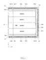
- FIG. 1is a schematic plan view showing the layout of a semiconductor chip of the semiconductor memory device according to a preferred embodiment of the present invention.
- the present embodimentis one example of a case in which the present invention is applied to DRAM, but the applicable scope of the present invention is not limited thereby.
- the configuration shown hereinmay be used in other arrays of circuits having relatively long lengths of I/O wiring including, but not limited to, other types of memories, logic circuits, processors, etc.
- the semiconductor memory deviceis formed on a semiconductor chip 100 having a memory cell area 10 provided with four memory banks BANK 0 to BANK 3 and a peripheral circuit area 20 positioned on the periphery of the memory cell area 10 , as shown in FIG. 1 .
- the peripheral circuit area 20includes a pad area 101 a and a first circuit area 102 a disposed along a peripheral edge 100 a of the semiconductor chip 100 , a pad area 101 b and a second circuit area 102 b disposed along a peripheral edge 100 b of the semiconductor chip 100 , and a pad area 101 c and a third circuit area 102 c disposed along a peripheral edge 100 c of the semiconductor chip 100 .
- the peripheral edge 100 a to 100 c of the semiconductor chip 100are substantially parallel to each other, each extending in the X direction. (Note, the terms X and Y direction are used for ease of reference and are not intended to imply a particular orientation of semiconductor chip 100 .)
- the peripheral edge 100 cis substantially orthogonal to the peripheral edge 100 a and 100 b and extends in the Y direction.
- a pad areais provided in the center of the semiconductor chip, but it is difficult to locate the pad area in the center of the semiconductor chip in cases in which there is a considerable number of data I/O pins (e.g., 32 pins or more).
- a plurality of pad areasare provided to the peripheral edge portions of the semiconductor chip 100 in such cases, as shown in FIG. 1 .
- Half of the data I/O pins(DQ 0 to DQ 15 in the example shown in FIG. 1 ) are disposed at least in the pad area 101 a
- the other half of the data I/O pins(DQ 16 to DQ 31 in the example shown in FIG. 1 ) are disposed at least in the pad area 101 b
- Address pins, command pins, clock pins, power source pins, and the like(not shown) are disposed in the pad area 101 c.
- the first circuit area 102 ahas an output buffer for outputting read data to the data I/O pins provided to the pad area 101 a , an input receiver for receiving write data supplied via the data I/O pins, and the like.
- the second circuit area 102 bhas an output buffer for outputting read data to the data I/O pins provided to the pad area 101 b , an input receiver for receiving the write data supplied via the data I/O pin, and the like.
- An address decoder, a command decoder, a DLL (delayed locked loop) circuit, an internal voltage generation circuit, and other peripheral circuitsare formed in the third circuit area 102 c.
- the memory cell area 10is disposed between the first circuit area 102 a and the second circuit area 102 b .
- the memory banks BANK 0 through BANK 3 provided to the memory cell area 10are arranged juxtaposed along the Y direction along a line that connects the first circuit area 102 a and the second circuit area 102 b.
- Each of the main I/O lines MIOthus connects the first circuit area 102 a disposed adjacent or in proximity to the peripheral edge 100 a of the semiconductor chip 100 , and the second circuit area 102 b disposed adjacent or in proximity to the peripheral edge 100 b of the semiconductor chip 100 . Therefore, the wiring length of the main I/O lines MIO is considerable. Specifically, the main I/O lines MIO have substantially the same length as one side of the semiconductor chip 100 in the Y direction, e.g., on the order of several to tens of millimeters. Therefore, not only is there considerable parasitic capacitance, but also the signal quality of read data on the main I/O line MIO tends to be adversely affected by the differences between the far and near ends. These problems can be efficiently alleviated by an assist circuit described below.
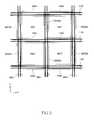
- FIG. 2is a schematic plan view showing a portion of one of the memory banks in enlarged form.
- each of the memory bankshas a multiplicity or plurality of memory mats MAT arranged in a matrix.
- the term “memory mat MAT”refers to a range in which a sub word line and a bit line extend.
- a sub word driver area SWDAis provided between each two adjacent memory mats MAT lying next to each other in the X direction.
- a sense amplifier area SAAis provided between each two adjacent memory mats MAT lying next to each other in the Y direction.
- a cross area XAis provided in a portion of the chip located at the intersection between (i) a column of sub word driver areas SWDA that extend in the Y direction and (ii) a row of sense amplifier areas SAA that extend in the X direction.
- the cross areas XAare shown hatched in FIG. 2 .
- a driver circuit and the like for driving the main I/O line MIOis disposed in each of the cross areas XA, as described below.
- FIG. 3is a schematic plan view showing a part of each of the memory banks in further enlarged.
- Local I/O lines LIOare formed on the rows of sense amplifier areas SAA that extend in the X direction, as shown in FIG. 3 .
- the main I/O lines MIOare formed on the column of the sub word driver areas SWDA that extend in the Y direction.
- the local I/O lines LIO and the main I/O lines MIOare hierarchically structured I/O lines.
- the local I/O lines LIOare used to perform an operation whereby read data that is stored in and read from a memory cell is transmitted inside the memory cell area 10 , and the main I/O lines MIO are used for transmitting the read data from the memory cell area 10 to the peripheral circuit area 20 .
- read data amplified by a sense amplifieris first transmitted to the local I/O lines LIO, and is then from there transmitted to the main I/O lines MIO.
- the main I/O lines MIOare connected to the circuit areas 102 a and 102 b , and read data transmitted via the main I/O lines MIO is ultimately output from the data I/O pins to the outside, e.g., to an external bus or device, as shown in FIG. 1 .
- the local I/O lines LIOare differential I/O lines that transmit read data by using a pair of wires or conductors as described below.
- the main I/O lines MIOare single-ended I/O lines that transmit read data by using a single wire or conductor.
- the required number of main I/O lines MIOincreases with an increasing number of bits in the simultaneously input and output data (i.e., with the data width), and the main I/O lines MIO are therefore configured as single-end lines in order to minimize this increase in the number of lines required.
- FIG. 4is a circuit diagram showing a configuration of a memory mat MAT, a sub word driver area SWDA, and a sense amplifier area SAA.
- Each of the sub word drivers SWD 0 , SWD 1 , . . .drive an associated one of the sub word lines WL 0 , WL 1 , . . . on the basis of a row address. That is, the row address is used to select the appropriate sub word line.
- Multiple sense amplifiers SA 0 , SA 1 , . . . and column switches YSW 0 , YSW 1 , . . .are provided to the sense amplifier area SAA.
- the sense amplifiers SA 0 , SA 1 , . . .are connected to the corresponding bit line pairs (e.g., pairs composed of bit lines BL 0 T, BL 0 B) and amplify a potential difference appearing in these bit line pairs.
- the column switches YSW 0 , YSW 1 , . . .are provided between the corresponding sense amplifiers and local I/O lines LIO, and are switched to an on state based on a corresponding column selection signal YSEL.
- the column switch YSW 0is connected between the sense amplifier SA 0 and the local I/O lines LIOT 0 and LIOB 0 . Therefore, the sense amplifier SA 0 and the local I/O lines LIOT 0 and LIOB 0 are electrically connected when the column selection signal YSEL is activated, i.e., goes high.
- the column selection signal YSELis activated on the basis of a column address.
- the present inventionis not limited by this configuration alone.
- the even-numbered column switches YSW 0 , YSW 2 , . . .are disposed in the sense amplifier area SAA positioned on one side (top of FIG. 4 ) as viewed from the memory mat MAT, and the odd-numbered column switches YSW 1 , YSW 3 , . . .
- the read data that has been simultaneously selected and passed through the column switches YSW 0 to YSW 3is transmitted via a pair of signal lines composed of LIOT 0 and LIOB 0 , a pair of signal lines composed of LIOT 1 and LIOB 1 , a pair of signal lines composed of LIOT 2 and LIOB 2 , and a pair of signal lines composed of LIOT 3 and LIOB 3 , respectively.
- Memory cells MCare placed at intersections between the word lines and the bit lines in the memory mat MAT, as shown in FIG. 4 .
- the memory cells MChave a configuration in which a memory cell transistor TR and a memory cell data storage capacitance C are connected in series between the corresponding bit lines and plate (ground or return paths) wirings.
- the memory cell transistor TRis composed of an N-channel MOS transistor, and the gate electrode thereof is connected to the corresponding word line.
- FIG. 5is a circuit diagram showing the configuration of the main part of a cross area XA.
- a single cross area XAincludes a multiplexer 120 , an equalizer 130 for equalizing a pair of internal wirings 110 T and 110 B, a data amplifier DA 0 for receiving the potential difference of the pair of internal wirings 110 T and 110 B, and a driver circuit MD 0 for receiving an output MDin of the data amplifier DA 0 , as shown in FIG. 5 .
- the multiplexer 120is a switching circuit for connecting the pair of internal wirings 110 T and 110 B to any of the local I/O lines LIO.
- the multiplexer 120is a switching circuit for connecting the pair of internal wirings 110 T and 110 B to any of the local I/O lines LIO.
- the cross area XAprovided with the data amplifier DA 0 and the driver circuit MD 0 , either the local I/O lines LIOT 0 and LIOB 0 , or the local I/O lines LIOT 2 , LIOB 2 are connected to the pair of internal wirings 110 T and 110 B.
- the selectionis performed on the basis of and in response to the column address.
- the equalizer 130is composed of three P-channel MOS transistors. When an equalize signal EQ is activated (changed to a low level), the pair of internal wirings 110 T and 110 B is equalized to the same electric potential.
- the data amplifier DA 0is an amplifier activated when an enable signal DAE 0 is raised to a high level (e.g., goes high).
- a high levele.g., goes high.
- the gate circuit 140is configured from a P-channel MOS transistor, as shown in FIG. 5 .
- the enable signal DAE 0is at a low level, the gate circuit 140 is switched on, and the power supply to the data amplifier DA 0 is interrupted.
- the output MDin of the data amplifier DA 0is thereby maintained at a low level.
- the driver circuit MD 0is configured from an N-channel MOS transistor, and the output signal MDin of the data amplifier DA 0 is supplied to the gate electrode thereof.
- the source of the transistor that constitutes the driver circuit MD 0is connected to a prescribed power source potential (e.g., ground potential), and the drain is connected to the main I/O line MIO 0 .
- This configurationallows the driver circuit MD 0 to discharge the main I/O lines MIO when the output MDin of the data amplifier DA 0 is at a high level, and has no effect on the main I/O lines MIO when the output MDin of the data amplifier DA 0 is at a low level.
- the above-described circuitis formed in each prescribed cross area XA, and drives each of the corresponding main I/O lines MIO 0 , MIO 1 , . . . .
- the main I/O lines MIOare provided so as to go across and span the memory banks BANK 0 to BANK 3 , with a single main I/O line MIO shared by these four memory banks BANK 0 to BANK 3 .
- One end of each of the main I/O lines MIOis connected to the first circuit area 102 a , and the other end is connected to the second circuit area 102 b.
- one end of the main I/O line MIO 0is connected to a read circuit 200 and a precharge circuit 300 formed on the first circuit area 102 a , and the other end is connected to an assist circuit 400 formed on the second circuit area 102 b , as shown in FIG. 5 .
- one end of the main I/O line MIO 1is connected to a read circuit 200 and a precharge circuit 300 formed on the second circuit area 102 b , and the other end is connected to an assist circuit 400 formed on the first circuit area 102 a.
- the read circuit 200is a circuit for receiving the read data in the main I/O lines MIO. Therefore, for purposes of reference with respect to the main I/O line MIO 0 , the memory bank BANK 0 is located at the far end (i.e., farthest from the associated read circuit 200 depicted at the bottom of FIG. 4 ), and the memory bank BANK 3 is located at the near end (i.e., closest to read circuit 200 ). Conversely, with respect to the main I/O line MIO 1 , the memory bank BANK 3 is located at the far end (farthest from associated read circuit 200 ), and the memory bank BANK 0 is located at the near end (closest to the associated read circuit 200 ). The configuration of the read circuit 200 is described below.
- the precharge circuit 300is a circuit for precharging the main I/O lines MIO discharged by the driver circuit MD 0 .
- the precharge circuit 300also has the function of supplying the write data to the main I/O lines MIO during a write operation.
- the configuration of the precharge circuit 300is further described below.
- the assist circuit 400is a circuit for amplifying the read data in the main I/O lines MIO, and has the function of minimizing loss of signal quality of read data caused by electrical difference between the far end and near end of the I/O line.
- the assist circuit 400is connected to the ends of the main I/O lines MIO that are on the side opposite from the associated read circuit 200 , i.e., is connected to the most distant or far end.
- the waveform of read data supplied to the read circuit 200varies considerably between those situations in which the main I/O lines MIO are discharged using a driver circuit connected near or at the near end, and those situations in which the main I/O lines MIO are discharged using a driver circuit connected near or at the far end. Specifically, the further the driver circuit for discharging the main I/O lines MIO is from the read circuit 200 , the more time it takes for the settled signal to propagate until the read circuit 200 receives the stabilized read data.
- the assist circuit 400is connected to the farthest ends of the main I/O lines. Therefore, amplification by the assist circuit 400 is performed progressively faster at points located closer to the far ends of the main I/O lines MIO, and the difference between the far end and near end can be efficiently reduced.
- the configuration of the assist circuit 400is further described below.
- FIG. 6is a circuit diagram of the read circuit 200 and the precharge circuit 300 .
- Two main I/O lines MIO 0 and MIO 1are connected to a single read circuit 200 via inverters 211 and 212 and multiplexers 221 and 222 , as shown in FIG. 6 .
- the multiplexers 221 and 222are selected on the basis of a column address.
- the read circuit 200has serially connected transistors 201 to 204 , and further has a latch circuit 205 for latching the logical level of the connection point A of transistors 202 and 203 .
- Both of the transistors 201 and 202are P-channel MOS transistors, and both of the transistors 203 and 204 are N-channel MOS transistors.
- An enable signal CRDAE and an inverted signal thereofare supplied to the gate electrodes of the transistors 202 and 203 , respectively.
- Each of the transistors 202 and 203can thereby be switched on when the enable signal CRDAE is at a low level, and the potential of the connection point A is determined by the logic level of the main I/O line MIO 0 or MIO 1 .
- the connection point Ais at a high level because a low level is applied to the gate electrodes of each of the transistors 201 and 204 if the read data in the main I/O line MIO is at the high level.
- a high levelis applied to the gate electrodes of both of the transistors 201 and 204 if the read data in the main I/O line MIO is at a low level, and the connection point A is therefore at a low level.
- the logic level of the connection point Ais latched by the latch circuit 205 .
- the read data latched by the latch circuit 205is output via a read/write bus or the like (not shown) from a data I/O pin provided to a pad area 100 a or 100 b .
- the content of the latch circuit 205is retained at least during a period in which the enable signal CRDAE is at a high level.
- Each precharge circuit 300is composed of serially connected transistors 301 and 302 and a control circuit 303 for controlling the transistors 301 and 302 .
- the transistor 301is a P-channel MOS transistor
- the transistor 302is an N-channel MOS transistor, as shown in FIG. 6 .
- the connection points B of the transistors 301 and 302are connected to the corresponding main I/O lines MIO.
- Each of the control circuits 303receives a write signal WRIT, a precharge signal PRE, and write data DATA so as to control the transistors 301 and 302 based on the combinations of these signals.
- the write signal WRITis activated to a high level during a write operation
- the precharge signal PREis activated to a high level during a precharge operation of the corresponding main I/O line MIO.
- FIG. 7is a logic or truth table describing operation of the control circuit 303 .
- Case #1 in FIG. 7is one in which high-level data is written to a memory cell, where the transistor 301 is switched on, and the transistor 302 is switched off.
- the main I/O line MIOis thereby driven to a high level via the transistor 301 .
- Case #2is one in which low-level data is written to a memory cell, where the transistor 301 is switched off, and the transistor 302 is switched on.
- the main I/O line MIOis thereby driven to a low level via the transistor 302 .
- Case #3is one in which the main I/O line MIO is pre-charged, where the transistor 301 is switched on, and the transistor 302 is switched off.
- the main I/O line MIOis thereby pre-charged via the transistor 302 .
- Case #4is one in which a read operation is performed by a read circuit 200 , where both the transistors 301 and 302 are switched off.
- the main I/O line MIOis thereby disconnected from the precharge circuit 300 .
- FIG. 8is a circuit diagram of the assist circuit 400 .
- the assist circuit 400has an N-channel MOS transistor 401 with its drain connected to the furthest end of the main I/O line MIO and source connected to a prescribed power source potential (e.g., ground potential), and further has a NOR circuit 402 for receiving an assist enable signal AE and the read data in the main I/O line MIO so as to generate a discharge signal DIS that is supplied to the gate electrode of the transistor 401 .
- a prescribed power source potentiale.g., ground potential
- the assist enable signal AEis an output signal of a NAND circuit 403 .
- An inverted signal of the write signal WRIT and an inverted signal of the precharge signal PREare supplied to the NAND circuit 403 , as shown in FIG. 8 .
- the assist enable signal AEis therefore activated to a low level when both the write signal WRIT and the precharge signal PRE reach the low level. As described with reference to FIG. 7 , this condition corresponds to a read operation performed by the read circuit 200 such that both the write signal WRIT and the precharge signal PRE reach a low level (case #4).
- the NOR circuit 402brings the discharge signal DIS to a high level and switches on the transistor 401 in response to a drop in the potential of the main I/O line MIO to a potential level below a prescribed threshold value. A discharge of the main I/O line MIO is thereby accelerated.
- the term “prescribed threshold value”refers to the threshold switching value of the transistors constituting the NOR circuit 402 .
- the NOR circuit 402has the circuit configuration shown in FIG. 9 . In this circuit, threshold values of the transistors 501 and 503 are the prescribed threshold value.
- An assist enable signal AEis supplied to the gate electrodes of the other transistors 502 and 504 . As shown in FIG. 9 , the transistors 501 and 502 are P-channel MOS transistors, and the transistors 503 and 504 are N-channel MOS transistors.
- the read data transmitted through the main I/O line MIOis amplified when the potential of the main I/O line MIO drops below the threshold value of the transistors 501 and 503 in a case in which the assist enable signal AE is at a low level.
- one of the write signal WRIT and precharge signal PREis at a high level during a write operation (cases #1, #2) or during a precharge operation (case #3).
- the assist enable signal AEis therefore at a high level
- the discharge signal DISwhich is the output of the NOR circuit 402 is fixed at a low level.
- the transistor 401is brought to a nonconductive off state (i.e., turns off).
- the assist circuit 400is thus deactivated during a write operation or during a precharge operation, and there is no effect on the main I/O line MIO.
- a main I/O line MIOcan be rapidly discharged because an assist circuit 400 is connected to the far end of the main I/O line MIO.
- a method involving the use of a larger driver circuit MDcan also be suggested here as a method for rapidly discharging the main I/O line MIO.
- driver circuits MDare installed at each of the large number of cross areas XA within a memory cell area 10 , chip size will dramatically increase if each of the driver circuits MD is made larger to increase its I/O line discharge rate.
- the chip sizeis only minimally affected in the present embodiment because merely providing an assist circuit 400 to a peripheral circuit area 20 is sufficient to mitigate I/O line signal propagation delays in devices having long I/O lines, rather than increasing the size of each individual driver circuit MD.
- the read circuit 200 connected to the main I/O line MIOcan therefore latch read data by a sufficient latch margin.
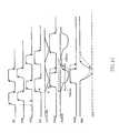
- FIG. 10is a timing chart showing the operation performed during a read operation in the semiconductor memory device according to the present embodiment.
- the selected memory bankstarts a read operation based on a row address when an internal read command RD is activated at time t 1 .
- a precharge signal PREis activated at a high level at time t 2 .
- the write signal WRITis kept at a low level during the read operation.
- the main I/O line MIOis thereby pre-charged because the transistor 301 shown in FIG. 6 turns on.
- the equalize signal EQis kept at a low level during this period, and the pair of internal wirings 110 T and 110 B shown in FIG. 5 is therefore equalized to the same electric potential.
- the equalize signal EQis “deactivated” to a high level at time t 3 , and a prescribed column selection signal YSEL is activated at time t 4 when the read operation based on the row address is completed and the pre-charging of the main I/O line MIO is completed. A selection is made based on a column address as to which column selection signal YSEL should be activated.
- the local I/O lines LIOT 0 and LIOB 0 shown in FIG. 4are thereby driven by a prescribed sense amplifier SA, and the potential difference between the local I/O lines LIOT 0 and LIOB 0 gradually expands.
- the enable signal DAE 0is activated to a high level at time t 5 .
- a potential differenceis provided to the signal DO/DOB that is input to a data amplifier DA 0 , and a change is induced in the output signal MDin of the data amplifier DA 0 to switch on the drive circuit MD 0 (or to keep the circuit in an off state) at time t 5 . It is determined by the logic level of read data whether the drive circuit MD 0 is switched on or is maintained in an off state.
- the drive circuit MD 0When the drive circuit MD 0 is switched on, the pre-charged main I/O line MIO 0 is discharged via the drive circuit MD 0 , and the electric potential thereof decreases.
- the transistor 401 in the assist circuit 400 shown in FIG. 8is switched on, and the discharging of the main I/O line MIO 0 is accelerated. The I/O line MIO 0 is thereby discharged rapidly.
- the enable signal CRDAEis then activated to a low level, and the read data is thereby latched by the latch circuit 205 in the read circuit 200 .
- the main I/O line MIO 0When the main I/O line MIO 0 is thus discharged by the drive circuit MD 0 in the present embodiment, the discharge is assisted by the assist circuit 400 , and the main I/O line MIO 0 can be rapidly discharged.
- the read data appearing in the read circuit 200can therefore be promptly established even in these cases in which the drive circuit MD 0 is positioned at the distant end, as viewed from the read circuit 200 .
- the waveformsare also shown by broken lines in FIG. 10 for a case in which the assist circuit 400 is absent. As is shown by the broken lines in FIG. 10 , the electric potential decreases relatively slowly and establishment of read data is also slow in the absence of the assist circuit 400 because the main I/O line MIO is discharged by the drive circuit MD 0 alone. This problem is particularly pronounced in cases in which the drive circuit MD 0 is positioned at the distant end, as viewed from the read circuit 200 .
- an assist circuit 400is provided at the distant end, as viewed from the read circuit 200 , and the above-described effects can therefore be obtained.
- a single assist circuit 400is, for example, connected to the farthest end of a main I/O line MIO, but the connection position of the assist circuit is not limited to this option alone, and the position may be farther away from a prescribed drive circuit included in a plurality of drive circuits, as viewed from the read circuit 200 .
- a plurality of assist circuits 400may be disposed between adjacent memory banks, as shown in FIG. 11A ; or an assist circuit 400 may be disposed within each of the memory banks, as shown in FIG. 11B . It is most effective, however, to connect an assist circuit 400 to the farthest end of the main I/O line MIO in order to reduce the difference between the far end and near end, as in the embodiment described above.
- the present inventioncan therefore be used in cases in which a peripheral circuit area is disposed in a center portion of a semiconductor chip, as in a large number of DRAMs.
- applying the present invention to a semiconductor memory device having such a layoutis the most effective because of the extremely long wiring of the main I/O lines MIO.
- an assist circuit 400is also connected to the main I/O lines for connecting memory cell areas and peripheral circuit areas, which are some of the hierarchically structured I/O lines, but the present invention is not limited to this option alone. Therefore, it is not necessary for the I/O lines to be hierarchically structured, and an assist circuit can be connected to any of the I/O lines. As described above, however, the main I/O lines for connecting memory cell areas and peripheral circuit areas have a particularly long wiring length, and connecting the assist circuit to such I/O lines therefore produces the greatest effect and advantage.
- an I/O line for connecting the assist circuitis not limited to a single-ended I/O line, and the assist circuit may also be connected to a differential I/O line.
- a single-ended I/O linerequires greater signal amplitude than does a differential I/O line, so that connecting the assist circuit to a single-ended I/O line, as in the above-described embodiment, is therefore particularly effective.
Landscapes
- Engineering & Computer Science (AREA)
- Microelectronics & Electronic Packaging (AREA)
- Computer Hardware Design (AREA)
- Databases & Information Systems (AREA)
- Dram (AREA)
Abstract
Description
Claims (20)
Priority Applications (2)
| Application Number | Priority Date | Filing Date | Title |
|---|---|---|---|
| US13/550,783US8699281B2 (en) | 2008-08-18 | 2012-07-17 | Semiconductor memory device and method with auxiliary I/O line assist circuit and functionality |
| US14/220,531US9177620B2 (en) | 2008-08-18 | 2014-03-20 | Semiconductor memory device and method with auxiliary I/O line assist circuit and functionality |
Applications Claiming Priority (2)
| Application Number | Priority Date | Filing Date | Title |
|---|---|---|---|
| IN1999/CHE/2008 | 2008-08-18 | ||
| IN1999CH2008 | 2008-08-18 |
Related Child Applications (1)
| Application Number | Title | Priority Date | Filing Date |
|---|---|---|---|
| US13/550,783ContinuationUS8699281B2 (en) | 2008-08-18 | 2012-07-17 | Semiconductor memory device and method with auxiliary I/O line assist circuit and functionality |
Publications (2)
| Publication Number | Publication Date |
|---|---|
| US20100039871A1 US20100039871A1 (en) | 2010-02-18 |
| US8259509B2true US8259509B2 (en) | 2012-09-04 |
Family
ID=41681185
Family Applications (3)
| Application Number | Title | Priority Date | Filing Date |
|---|---|---|---|
| US12/543,262Expired - Fee RelatedUS8259509B2 (en) | 2008-08-18 | 2009-08-18 | Semiconductor memory device and method with auxiliary I/O line assist circuit and functionality |
| US13/550,783Expired - Fee RelatedUS8699281B2 (en) | 2008-08-18 | 2012-07-17 | Semiconductor memory device and method with auxiliary I/O line assist circuit and functionality |
| US14/220,531ActiveUS9177620B2 (en) | 2008-08-18 | 2014-03-20 | Semiconductor memory device and method with auxiliary I/O line assist circuit and functionality |
Family Applications After (2)
| Application Number | Title | Priority Date | Filing Date |
|---|---|---|---|
| US13/550,783Expired - Fee RelatedUS8699281B2 (en) | 2008-08-18 | 2012-07-17 | Semiconductor memory device and method with auxiliary I/O line assist circuit and functionality |
| US14/220,531ActiveUS9177620B2 (en) | 2008-08-18 | 2014-03-20 | Semiconductor memory device and method with auxiliary I/O line assist circuit and functionality |
Country Status (1)
| Country | Link |
|---|---|
| US (3) | US8259509B2 (en) |
Cited By (3)
| Publication number | Priority date | Publication date | Assignee | Title |
|---|---|---|---|---|
| US20110141829A1 (en)* | 2009-12-14 | 2011-06-16 | Ware Frederick A | Circuits for Reducing Power Consumption of Memory Components |
| US8699281B2 (en)* | 2008-08-18 | 2014-04-15 | Elpida Memory Inc. | Semiconductor memory device and method with auxiliary I/O line assist circuit and functionality |
| US9679614B1 (en) | 2015-11-25 | 2017-06-13 | Micron Technology, Inc. | Semiconductor device with single ended main I/O line |
Families Citing this family (138)
| Publication number | Priority date | Publication date | Assignee | Title |
|---|---|---|---|---|
| US9158667B2 (en) | 2013-03-04 | 2015-10-13 | Micron Technology, Inc. | Apparatuses and methods for performing logical operations using sensing circuitry |
| US8964496B2 (en) | 2013-07-26 | 2015-02-24 | Micron Technology, Inc. | Apparatuses and methods for performing compare operations using sensing circuitry |
| US8971124B1 (en) | 2013-08-08 | 2015-03-03 | Micron Technology, Inc. | Apparatuses and methods for performing logical operations using sensing circuitry |
| US9153305B2 (en) | 2013-08-30 | 2015-10-06 | Micron Technology, Inc. | Independently addressable memory array address spaces |
| US9019785B2 (en) | 2013-09-19 | 2015-04-28 | Micron Technology, Inc. | Data shifting via a number of isolation devices |
| US9449675B2 (en) | 2013-10-31 | 2016-09-20 | Micron Technology, Inc. | Apparatuses and methods for identifying an extremum value stored in an array of memory cells |
| US9430191B2 (en) | 2013-11-08 | 2016-08-30 | Micron Technology, Inc. | Division operations for memory |
| US9934856B2 (en) | 2014-03-31 | 2018-04-03 | Micron Technology, Inc. | Apparatuses and methods for comparing data patterns in memory |
| US9711207B2 (en) | 2014-06-05 | 2017-07-18 | Micron Technology, Inc. | Performing logical operations using sensing circuitry |
| US9449674B2 (en) | 2014-06-05 | 2016-09-20 | Micron Technology, Inc. | Performing logical operations using sensing circuitry |
| US9496023B2 (en) | 2014-06-05 | 2016-11-15 | Micron Technology, Inc. | Comparison operations on logical representations of values in memory |
| US10074407B2 (en) | 2014-06-05 | 2018-09-11 | Micron Technology, Inc. | Apparatuses and methods for performing invert operations using sensing circuitry |
| US9704540B2 (en) | 2014-06-05 | 2017-07-11 | Micron Technology, Inc. | Apparatuses and methods for parity determination using sensing circuitry |
| US9711206B2 (en) | 2014-06-05 | 2017-07-18 | Micron Technology, Inc. | Performing logical operations using sensing circuitry |
| US9779019B2 (en) | 2014-06-05 | 2017-10-03 | Micron Technology, Inc. | Data storage layout |
| US9910787B2 (en) | 2014-06-05 | 2018-03-06 | Micron Technology, Inc. | Virtual address table |
| US9786335B2 (en) | 2014-06-05 | 2017-10-10 | Micron Technology, Inc. | Apparatuses and methods for performing logical operations using sensing circuitry |
| US9455020B2 (en) | 2014-06-05 | 2016-09-27 | Micron Technology, Inc. | Apparatuses and methods for performing an exclusive or operation using sensing circuitry |
| US9830999B2 (en) | 2014-06-05 | 2017-11-28 | Micron Technology, Inc. | Comparison operations in memory |
| US9747961B2 (en) | 2014-09-03 | 2017-08-29 | Micron Technology, Inc. | Division operations in memory |
| US9898252B2 (en) | 2014-09-03 | 2018-02-20 | Micron Technology, Inc. | Multiplication operations in memory |
| US9904515B2 (en) | 2014-09-03 | 2018-02-27 | Micron Technology, Inc. | Multiplication operations in memory |
| US10068652B2 (en) | 2014-09-03 | 2018-09-04 | Micron Technology, Inc. | Apparatuses and methods for determining population count |
| US9847110B2 (en) | 2014-09-03 | 2017-12-19 | Micron Technology, Inc. | Apparatuses and methods for storing a data value in multiple columns of an array corresponding to digits of a vector |
| US9740607B2 (en) | 2014-09-03 | 2017-08-22 | Micron Technology, Inc. | Swap operations in memory |
| US9589602B2 (en) | 2014-09-03 | 2017-03-07 | Micron Technology, Inc. | Comparison operations in memory |
| US9836218B2 (en) | 2014-10-03 | 2017-12-05 | Micron Technology, Inc. | Computing reduction and prefix sum operations in memory |
| US9940026B2 (en) | 2014-10-03 | 2018-04-10 | Micron Technology, Inc. | Multidimensional contiguous memory allocation |
| US10163467B2 (en) | 2014-10-16 | 2018-12-25 | Micron Technology, Inc. | Multiple endianness compatibility |
| US10147480B2 (en) | 2014-10-24 | 2018-12-04 | Micron Technology, Inc. | Sort operation in memory |
| US9779784B2 (en) | 2014-10-29 | 2017-10-03 | Micron Technology, Inc. | Apparatuses and methods for performing logical operations using sensing circuitry |
| US10073635B2 (en) | 2014-12-01 | 2018-09-11 | Micron Technology, Inc. | Multiple endianness compatibility |
| US9747960B2 (en) | 2014-12-01 | 2017-08-29 | Micron Technology, Inc. | Apparatuses and methods for converting a mask to an index |
| US10061590B2 (en) | 2015-01-07 | 2018-08-28 | Micron Technology, Inc. | Generating and executing a control flow |
| US10032493B2 (en) | 2015-01-07 | 2018-07-24 | Micron Technology, Inc. | Longest element length determination in memory |
| US9583163B2 (en) | 2015-02-03 | 2017-02-28 | Micron Technology, Inc. | Loop structure for operations in memory |
| WO2016126472A1 (en) | 2015-02-06 | 2016-08-11 | Micron Technology, Inc. | Apparatuses and methods for scatter and gather |
| CN107408405B (en) | 2015-02-06 | 2021-03-05 | 美光科技公司 | Apparatus and method for parallel writing to multiple memory device locations |
| CN107408404B (en) | 2015-02-06 | 2021-02-12 | 美光科技公司 | Apparatus and methods for memory devices as storage of program instructions |
| CN107408408B (en) | 2015-03-10 | 2021-03-05 | 美光科技公司 | Apparatus and method for shift determination |
| US9741399B2 (en) | 2015-03-11 | 2017-08-22 | Micron Technology, Inc. | Data shift by elements of a vector in memory |
| US9898253B2 (en) | 2015-03-11 | 2018-02-20 | Micron Technology, Inc. | Division operations on variable length elements in memory |
| US10365851B2 (en) | 2015-03-12 | 2019-07-30 | Micron Technology, Inc. | Apparatuses and methods for data movement |
| US10146537B2 (en) | 2015-03-13 | 2018-12-04 | Micron Technology, Inc. | Vector population count determination in memory |
| US10049054B2 (en) | 2015-04-01 | 2018-08-14 | Micron Technology, Inc. | Virtual register file |
| US10140104B2 (en) | 2015-04-14 | 2018-11-27 | Micron Technology, Inc. | Target architecture determination |
| US9959923B2 (en)* | 2015-04-16 | 2018-05-01 | Micron Technology, Inc. | Apparatuses and methods to reverse data stored in memory |
| US10073786B2 (en) | 2015-05-28 | 2018-09-11 | Micron Technology, Inc. | Apparatuses and methods for compute enabled cache |
| US9704541B2 (en) | 2015-06-12 | 2017-07-11 | Micron Technology, Inc. | Simulating access lines |
| US9921777B2 (en) | 2015-06-22 | 2018-03-20 | Micron Technology, Inc. | Apparatuses and methods for data transfer from sensing circuitry to a controller |
| US9996479B2 (en) | 2015-08-17 | 2018-06-12 | Micron Technology, Inc. | Encryption of executables in computational memory |
| US9905276B2 (en) | 2015-12-21 | 2018-02-27 | Micron Technology, Inc. | Control of sensing components in association with performing operations |
| US9952925B2 (en) | 2016-01-06 | 2018-04-24 | Micron Technology, Inc. | Error code calculation on sensing circuitry |
| US10048888B2 (en) | 2016-02-10 | 2018-08-14 | Micron Technology, Inc. | Apparatuses and methods for partitioned parallel data movement |
| US9892767B2 (en) | 2016-02-12 | 2018-02-13 | Micron Technology, Inc. | Data gathering in memory |
| US9971541B2 (en) | 2016-02-17 | 2018-05-15 | Micron Technology, Inc. | Apparatuses and methods for data movement |
| US10956439B2 (en) | 2016-02-19 | 2021-03-23 | Micron Technology, Inc. | Data transfer with a bit vector operation device |
| US9899070B2 (en) | 2016-02-19 | 2018-02-20 | Micron Technology, Inc. | Modified decode for corner turn |
| US9697876B1 (en) | 2016-03-01 | 2017-07-04 | Micron Technology, Inc. | Vertical bit vector shift in memory |
| US10262721B2 (en) | 2016-03-10 | 2019-04-16 | Micron Technology, Inc. | Apparatuses and methods for cache invalidate |
| US9997232B2 (en) | 2016-03-10 | 2018-06-12 | Micron Technology, Inc. | Processing in memory (PIM) capable memory device having sensing circuitry performing logic operations |
| US10379772B2 (en) | 2016-03-16 | 2019-08-13 | Micron Technology, Inc. | Apparatuses and methods for operations using compressed and decompressed data |
| US9910637B2 (en) | 2016-03-17 | 2018-03-06 | Micron Technology, Inc. | Signed division in memory |
| US10120740B2 (en) | 2016-03-22 | 2018-11-06 | Micron Technology, Inc. | Apparatus and methods for debugging on a memory device |
| US11074988B2 (en) | 2016-03-22 | 2021-07-27 | Micron Technology, Inc. | Apparatus and methods for debugging on a host and memory device |
| US10388393B2 (en) | 2016-03-22 | 2019-08-20 | Micron Technology, Inc. | Apparatus and methods for debugging on a host and memory device |
| US10474581B2 (en) | 2016-03-25 | 2019-11-12 | Micron Technology, Inc. | Apparatuses and methods for cache operations |
| US10977033B2 (en) | 2016-03-25 | 2021-04-13 | Micron Technology, Inc. | Mask patterns generated in memory from seed vectors |
| US10074416B2 (en) | 2016-03-28 | 2018-09-11 | Micron Technology, Inc. | Apparatuses and methods for data movement |
| US10430244B2 (en) | 2016-03-28 | 2019-10-01 | Micron Technology, Inc. | Apparatuses and methods to determine timing of operations |
| US10453502B2 (en) | 2016-04-04 | 2019-10-22 | Micron Technology, Inc. | Memory bank power coordination including concurrently performing a memory operation in a selected number of memory regions |
| US10607665B2 (en) | 2016-04-07 | 2020-03-31 | Micron Technology, Inc. | Span mask generation |
| US9818459B2 (en) | 2016-04-19 | 2017-11-14 | Micron Technology, Inc. | Invert operations using sensing circuitry |
| US10153008B2 (en) | 2016-04-20 | 2018-12-11 | Micron Technology, Inc. | Apparatuses and methods for performing corner turn operations using sensing circuitry |
| US9659605B1 (en) | 2016-04-20 | 2017-05-23 | Micron Technology, Inc. | Apparatuses and methods for performing corner turn operations using sensing circuitry |
| US10042608B2 (en) | 2016-05-11 | 2018-08-07 | Micron Technology, Inc. | Signed division in memory |
| US9659610B1 (en) | 2016-05-18 | 2017-05-23 | Micron Technology, Inc. | Apparatuses and methods for shifting data |
| US10049707B2 (en) | 2016-06-03 | 2018-08-14 | Micron Technology, Inc. | Shifting data |
| US10387046B2 (en) | 2016-06-22 | 2019-08-20 | Micron Technology, Inc. | Bank to bank data transfer |
| US10037785B2 (en) | 2016-07-08 | 2018-07-31 | Micron Technology, Inc. | Scan chain operation in sensing circuitry |
| US10388360B2 (en) | 2016-07-19 | 2019-08-20 | Micron Technology, Inc. | Utilization of data stored in an edge section of an array |
| US10733089B2 (en) | 2016-07-20 | 2020-08-04 | Micron Technology, Inc. | Apparatuses and methods for write address tracking |
| US10387299B2 (en) | 2016-07-20 | 2019-08-20 | Micron Technology, Inc. | Apparatuses and methods for transferring data |
| US9767864B1 (en) | 2016-07-21 | 2017-09-19 | Micron Technology, Inc. | Apparatuses and methods for storing a data value in a sensing circuitry element |
| US9972367B2 (en) | 2016-07-21 | 2018-05-15 | Micron Technology, Inc. | Shifting data in sensing circuitry |
| US10303632B2 (en) | 2016-07-26 | 2019-05-28 | Micron Technology, Inc. | Accessing status information |
| US10468087B2 (en) | 2016-07-28 | 2019-11-05 | Micron Technology, Inc. | Apparatuses and methods for operations in a self-refresh state |
| US9990181B2 (en) | 2016-08-03 | 2018-06-05 | Micron Technology, Inc. | Apparatuses and methods for random number generation |
| US11029951B2 (en) | 2016-08-15 | 2021-06-08 | Micron Technology, Inc. | Smallest or largest value element determination |
| US10606587B2 (en) | 2016-08-24 | 2020-03-31 | Micron Technology, Inc. | Apparatus and methods related to microcode instructions indicating instruction types |
| US10466928B2 (en) | 2016-09-15 | 2019-11-05 | Micron Technology, Inc. | Updating a register in memory |
| US10387058B2 (en) | 2016-09-29 | 2019-08-20 | Micron Technology, Inc. | Apparatuses and methods to change data category values |
| US10014034B2 (en) | 2016-10-06 | 2018-07-03 | Micron Technology, Inc. | Shifting data in sensing circuitry |
| US10529409B2 (en) | 2016-10-13 | 2020-01-07 | Micron Technology, Inc. | Apparatuses and methods to perform logical operations using sensing circuitry |
| US9805772B1 (en) | 2016-10-20 | 2017-10-31 | Micron Technology, Inc. | Apparatuses and methods to selectively perform logical operations |
| CN207637499U (en) | 2016-11-08 | 2018-07-20 | 美光科技公司 | The equipment for being used to form the computation module above memory cell array |
| US10423353B2 (en) | 2016-11-11 | 2019-09-24 | Micron Technology, Inc. | Apparatuses and methods for memory alignment |
| US9761300B1 (en) | 2016-11-22 | 2017-09-12 | Micron Technology, Inc. | Data shift apparatuses and methods |
| US10402340B2 (en) | 2017-02-21 | 2019-09-03 | Micron Technology, Inc. | Memory array page table walk |
| US10403352B2 (en) | 2017-02-22 | 2019-09-03 | Micron Technology, Inc. | Apparatuses and methods for compute in data path |
| US10268389B2 (en) | 2017-02-22 | 2019-04-23 | Micron Technology, Inc. | Apparatuses and methods for in-memory operations |
| US10838899B2 (en) | 2017-03-21 | 2020-11-17 | Micron Technology, Inc. | Apparatuses and methods for in-memory data switching networks |
| US11222260B2 (en) | 2017-03-22 | 2022-01-11 | Micron Technology, Inc. | Apparatuses and methods for operating neural networks |
| US10185674B2 (en) | 2017-03-22 | 2019-01-22 | Micron Technology, Inc. | Apparatus and methods for in data path compute operations |
| US10049721B1 (en) | 2017-03-27 | 2018-08-14 | Micron Technology, Inc. | Apparatuses and methods for in-memory operations |
| US10147467B2 (en) | 2017-04-17 | 2018-12-04 | Micron Technology, Inc. | Element value comparison in memory |
| US10043570B1 (en) | 2017-04-17 | 2018-08-07 | Micron Technology, Inc. | Signed element compare in memory |
| US9997212B1 (en) | 2017-04-24 | 2018-06-12 | Micron Technology, Inc. | Accessing data in memory |
| US10942843B2 (en) | 2017-04-25 | 2021-03-09 | Micron Technology, Inc. | Storing data elements of different lengths in respective adjacent rows or columns according to memory shapes |
| US10236038B2 (en) | 2017-05-15 | 2019-03-19 | Micron Technology, Inc. | Bank to bank data transfer |
| US10068664B1 (en) | 2017-05-19 | 2018-09-04 | Micron Technology, Inc. | Column repair in memory |
| US10013197B1 (en) | 2017-06-01 | 2018-07-03 | Micron Technology, Inc. | Shift skip |
| US10262701B2 (en) | 2017-06-07 | 2019-04-16 | Micron Technology, Inc. | Data transfer between subarrays in memory |
| US10152271B1 (en) | 2017-06-07 | 2018-12-11 | Micron Technology, Inc. | Data replication |
| US10318168B2 (en) | 2017-06-19 | 2019-06-11 | Micron Technology, Inc. | Apparatuses and methods for simultaneous in data path compute operations |
| US10162005B1 (en) | 2017-08-09 | 2018-12-25 | Micron Technology, Inc. | Scan chain operations |
| US10534553B2 (en) | 2017-08-30 | 2020-01-14 | Micron Technology, Inc. | Memory array accessibility |
| US10416927B2 (en) | 2017-08-31 | 2019-09-17 | Micron Technology, Inc. | Processing in memory |
| US10346092B2 (en) | 2017-08-31 | 2019-07-09 | Micron Technology, Inc. | Apparatuses and methods for in-memory operations using timing circuitry |
| US10741239B2 (en) | 2017-08-31 | 2020-08-11 | Micron Technology, Inc. | Processing in memory device including a row address strobe manager |
| US10409739B2 (en) | 2017-10-24 | 2019-09-10 | Micron Technology, Inc. | Command selection policy |
| US10522210B2 (en) | 2017-12-14 | 2019-12-31 | Micron Technology, Inc. | Apparatuses and methods for subarray addressing |
| US10332586B1 (en) | 2017-12-19 | 2019-06-25 | Micron Technology, Inc. | Apparatuses and methods for subrow addressing |
| US10614875B2 (en) | 2018-01-30 | 2020-04-07 | Micron Technology, Inc. | Logical operations using memory cells |
| US11194477B2 (en) | 2018-01-31 | 2021-12-07 | Micron Technology, Inc. | Determination of a match between data values stored by three or more arrays |
| US10437557B2 (en) | 2018-01-31 | 2019-10-08 | Micron Technology, Inc. | Determination of a match between data values stored by several arrays |
| US10725696B2 (en) | 2018-04-12 | 2020-07-28 | Micron Technology, Inc. | Command selection policy with read priority |
| US10440341B1 (en) | 2018-06-07 | 2019-10-08 | Micron Technology, Inc. | Image processor formed in an array of memory cells |
| US11175915B2 (en) | 2018-10-10 | 2021-11-16 | Micron Technology, Inc. | Vector registers implemented in memory |
| US10769071B2 (en) | 2018-10-10 | 2020-09-08 | Micron Technology, Inc. | Coherent memory access |
| US10483978B1 (en) | 2018-10-16 | 2019-11-19 | Micron Technology, Inc. | Memory device processing |
| US11184446B2 (en) | 2018-12-05 | 2021-11-23 | Micron Technology, Inc. | Methods and apparatus for incentivizing participation in fog networks |
| US12118056B2 (en) | 2019-05-03 | 2024-10-15 | Micron Technology, Inc. | Methods and apparatus for performing matrix transformations within a memory array |
| US10867655B1 (en) | 2019-07-08 | 2020-12-15 | Micron Technology, Inc. | Methods and apparatus for dynamically adjusting performance of partitioned memory |
| US11360768B2 (en) | 2019-08-14 | 2022-06-14 | Micron Technolgy, Inc. | Bit string operations in memory |
| US11449577B2 (en) | 2019-11-20 | 2022-09-20 | Micron Technology, Inc. | Methods and apparatus for performing video processing matrix operations within a memory array |
| US11853385B2 (en) | 2019-12-05 | 2023-12-26 | Micron Technology, Inc. | Methods and apparatus for performing diversity matrix operations within a memory array |
| US11227641B1 (en) | 2020-07-21 | 2022-01-18 | Micron Technology, Inc. | Arithmetic operations in memory |
Citations (12)
| Publication number | Priority date | Publication date | Assignee | Title |
|---|---|---|---|---|
| JPS6299988A (en) | 1985-10-25 | 1987-05-09 | Hitachi Ltd | semiconductor storage device |
| JPH0374722A (en) | 1989-08-16 | 1991-03-29 | Matsushita Electric Ind Co Ltd | bus circuit |
| JPH08138377A (en) | 1994-11-08 | 1996-05-31 | Hitachi Ltd | Semiconductor memory device |
| JPH08255479A (en) | 1995-03-20 | 1996-10-01 | Fujitsu Ltd | Semiconductor memory device |
| JPH08329685A (en) | 1995-06-02 | 1996-12-13 | Nec Corp | Semiconductor device |
| US5621679A (en)* | 1994-05-20 | 1997-04-15 | Samsung Electronics Co., Ltd. | Semiconductor memory device for achieving high bandwidth and method for arranging signal lines therefor |
| JPH11149769A (en) | 1997-09-19 | 1999-06-02 | Siemens Ag | Dynamic random access memory, semiconductor memory device, and method for activating word line of semiconductor memory device |
| US6198679B1 (en)* | 1998-09-29 | 2001-03-06 | Texas Instruments Incorporated | Semiconductor memory device |
| US20020015350A1 (en)* | 1998-05-22 | 2002-02-07 | Mitsubishi Denki Kabushiki Kaisha | Fast accessible semiconductor memory device |
| US20020027818A1 (en)* | 1998-07-22 | 2002-03-07 | Mitsubishi Denki Kabushiki Kaisha | Semiconductor memory device permitting improved integration density and reduced accessing time |
| JP2003007064A (en) | 2001-06-20 | 2003-01-10 | Hitachi Ltd | Semiconductor device |
| JP2005085289A (en) | 2003-09-04 | 2005-03-31 | Elpida Memory Inc | Semiconductor storage device |
Family Cites Families (2)
| Publication number | Priority date | Publication date | Assignee | Title |
|---|---|---|---|---|
| JP5193419B2 (en)* | 2005-10-28 | 2013-05-08 | 株式会社東芝 | Spin injection magnetic random access memory and writing method thereof |
| US8259509B2 (en)* | 2008-08-18 | 2012-09-04 | Elpida Memory, Inc. | Semiconductor memory device and method with auxiliary I/O line assist circuit and functionality |
- 2009
- 2009-08-18USUS12/543,262patent/US8259509B2/ennot_activeExpired - Fee Related
- 2012
- 2012-07-17USUS13/550,783patent/US8699281B2/ennot_activeExpired - Fee Related
- 2014
- 2014-03-20USUS14/220,531patent/US9177620B2/enactiveActive
Patent Citations (14)
| Publication number | Priority date | Publication date | Assignee | Title |
|---|---|---|---|---|
| JPS6299988A (en) | 1985-10-25 | 1987-05-09 | Hitachi Ltd | semiconductor storage device |
| JPH0374722A (en) | 1989-08-16 | 1991-03-29 | Matsushita Electric Ind Co Ltd | bus circuit |
| US5621679A (en)* | 1994-05-20 | 1997-04-15 | Samsung Electronics Co., Ltd. | Semiconductor memory device for achieving high bandwidth and method for arranging signal lines therefor |
| JPH08138377A (en) | 1994-11-08 | 1996-05-31 | Hitachi Ltd | Semiconductor memory device |
| JPH08255479A (en) | 1995-03-20 | 1996-10-01 | Fujitsu Ltd | Semiconductor memory device |
| JPH08329685A (en) | 1995-06-02 | 1996-12-13 | Nec Corp | Semiconductor device |
| JPH11149769A (en) | 1997-09-19 | 1999-06-02 | Siemens Ag | Dynamic random access memory, semiconductor memory device, and method for activating word line of semiconductor memory device |
| US6034913A (en) | 1997-09-19 | 2000-03-07 | Siemens Microelectronics, Inc. | Apparatus and method for high-speed wordline driving with low area overhead |
| US20020015350A1 (en)* | 1998-05-22 | 2002-02-07 | Mitsubishi Denki Kabushiki Kaisha | Fast accessible semiconductor memory device |
| US20020027818A1 (en)* | 1998-07-22 | 2002-03-07 | Mitsubishi Denki Kabushiki Kaisha | Semiconductor memory device permitting improved integration density and reduced accessing time |
| US6198679B1 (en)* | 1998-09-29 | 2001-03-06 | Texas Instruments Incorporated | Semiconductor memory device |
| JP2003007064A (en) | 2001-06-20 | 2003-01-10 | Hitachi Ltd | Semiconductor device |
| JP2005085289A (en) | 2003-09-04 | 2005-03-31 | Elpida Memory Inc | Semiconductor storage device |
| US7193915B2 (en) | 2003-09-04 | 2007-03-20 | Elpida Memory, Inc. | Semiconductor memory device |
Non-Patent Citations (1)
| Title |
|---|
| Japanese Office Action dated Oct. 11, 2011 (with a partial English translation). |
Cited By (5)
| Publication number | Priority date | Publication date | Assignee | Title |
|---|---|---|---|---|
| US8699281B2 (en)* | 2008-08-18 | 2014-04-15 | Elpida Memory Inc. | Semiconductor memory device and method with auxiliary I/O line assist circuit and functionality |
| US9177620B2 (en) | 2008-08-18 | 2015-11-03 | Ps4 Luxco S.A.R.L. | Semiconductor memory device and method with auxiliary I/O line assist circuit and functionality |
| US20110141829A1 (en)* | 2009-12-14 | 2011-06-16 | Ware Frederick A | Circuits for Reducing Power Consumption of Memory Components |
| US9679614B1 (en) | 2015-11-25 | 2017-06-13 | Micron Technology, Inc. | Semiconductor device with single ended main I/O line |
| US9824725B2 (en) | 2015-11-25 | 2017-11-21 | Micron Technology, Inc. | Semiconductor device with single ended main I/O line |
Also Published As
| Publication number | Publication date |
|---|---|
| US8699281B2 (en) | 2014-04-15 |
| US20120281486A1 (en) | 2012-11-08 |
| US9177620B2 (en) | 2015-11-03 |
| US20140204692A1 (en) | 2014-07-24 |
| US20100039871A1 (en) | 2010-02-18 |
Similar Documents
| Publication | Publication Date | Title |
|---|---|---|
| US8259509B2 (en) | Semiconductor memory device and method with auxiliary I/O line assist circuit and functionality | |
| US6172918B1 (en) | Semiconductor memory device allowing high-speed operation of internal data buses | |
| US10607689B2 (en) | Apparatuses and methods for providing driving signals in semiconductor devices | |
| US20030193824A1 (en) | Semiconductor memory device | |
| US9530459B2 (en) | Semiconductor memory device including a repeater circuit on main data lines | |
| KR20040038449A (en) | Semiconductor memory device having hierachical data input/output line and method for precharging therefor | |
| CN113113057B (en) | Semiconductor device having single-ended main I/O line | |
| US6449198B1 (en) | Semiconductor memory device | |
| JP4118364B2 (en) | Semiconductor memory device | |
| USRE36169E (en) | Semiconductor memory device | |
| KR100322541B1 (en) | Input and output line equalizing circuit and memory device having the same | |
| US6515927B2 (en) | Semiconductor memory having a wide bus-bandwidth for input/output data | |
| JP3773400B2 (en) | Multi-bank memory device and input / output line arrangement method | |
| US7817491B2 (en) | Bank control device and semiconductor device including the same | |
| US7289385B2 (en) | Bank selection signal control circuit for use in semiconductor memory device, and bank selection control method | |
| US6359825B1 (en) | Dynamic memory with increased access speed and reduced chip area | |
| KR100990140B1 (en) | Semiconductor memory device | |
| KR101069670B1 (en) | Semiconductor memory arraratus | |
| JP5431066B2 (en) | Semiconductor device | |
| US9396773B2 (en) | Semiconductor device | |
| US7359267B2 (en) | Method of transferring data | |
| US20230078117A1 (en) | Apparatuses including and methods for memory subword driver circuits with reduced gate induced drain leakage | |
| US7190632B2 (en) | Semiconductor memory device having improved column selection lines and method of driving the same | |
| KR100702767B1 (en) | Local Data Bus Precharge Circuit for High Speed Operation of Semiconductor Memory Devices | |
| KR20170037203A (en) | Semiconductor device |
Legal Events
| Date | Code | Title | Description |
|---|---|---|---|
| AS | Assignment | Owner name:ELPIDA MEMORY, INC.,JAPAN Free format text:ASSIGNMENT OF ASSIGNORS INTEREST;ASSIGNORS:RAO, SHETTI SHANMUKHESHWARA;GOEL, ANKUR;REEL/FRAME:023125/0775 Effective date:20090805 Owner name:ELPIDA MEMORY, INC., JAPAN Free format text:ASSIGNMENT OF ASSIGNORS INTEREST;ASSIGNORS:RAO, SHETTI SHANMUKHESHWARA;GOEL, ANKUR;REEL/FRAME:023125/0775 Effective date:20090805 | |
| ZAAA | Notice of allowance and fees due | Free format text:ORIGINAL CODE: NOA | |
| ZAAB | Notice of allowance mailed | Free format text:ORIGINAL CODE: MN/=. | |
| STCF | Information on status: patent grant | Free format text:PATENTED CASE | |
| FEPP | Fee payment procedure | Free format text:PAYOR NUMBER ASSIGNED (ORIGINAL EVENT CODE: ASPN); ENTITY STATUS OF PATENT OWNER: LARGE ENTITY | |
| AS | Assignment | Owner name:ELPIDA MEMORY INC., JAPAN Free format text:SECURITY AGREEMENT;ASSIGNOR:PS4 LUXCO S.A.R.L.;REEL/FRAME:032414/0261 Effective date:20130726 | |
| AS | Assignment | Owner name:PS4 LUXCO S.A.R.L., LUXEMBOURG Free format text:ASSIGNMENT OF ASSIGNORS INTEREST;ASSIGNOR:ELPIDA MEMORY, INC.;REEL/FRAME:032899/0588 Effective date:20130726 | |
| FEPP | Fee payment procedure | Free format text:PAYER NUMBER DE-ASSIGNED (ORIGINAL EVENT CODE: RMPN); ENTITY STATUS OF PATENT OWNER: LARGE ENTITY Free format text:PAYOR NUMBER ASSIGNED (ORIGINAL EVENT CODE: ASPN); ENTITY STATUS OF PATENT OWNER: LARGE ENTITY | |
| FPAY | Fee payment | Year of fee payment:4 | |
| AS | Assignment | Owner name:PS5 LUXCO S.A.R.L., LUXEMBOURG Free format text:ASSIGNMENT OF ASSIGNORS INTEREST;ASSIGNOR:PS4 LUXCO S.A.R.L.;REEL/FRAME:039818/0506 Effective date:20130829 Owner name:LONGITUDE SEMICONDUCTOR S.A.R.L., LUXEMBOURG Free format text:CHANGE OF NAME;ASSIGNOR:PS5 LUXCO S.A.R.L.;REEL/FRAME:039793/0880 Effective date:20131112 | |
| AS | Assignment | Owner name:LONGITUDE LICENSING LIMITED, IRELAND Free format text:ASSIGNMENT OF ASSIGNORS INTEREST;ASSIGNOR:LONGITUDE SEMICONDUCTOR S.A.R.L.;REEL/FRAME:046867/0248 Effective date:20180731 | |
| MAFP | Maintenance fee payment | Free format text:PAYMENT OF MAINTENANCE FEE, 8TH YEAR, LARGE ENTITY (ORIGINAL EVENT CODE: M1552); ENTITY STATUS OF PATENT OWNER: LARGE ENTITY Year of fee payment:8 | |
| FEPP | Fee payment procedure | Free format text:MAINTENANCE FEE REMINDER MAILED (ORIGINAL EVENT CODE: REM.); ENTITY STATUS OF PATENT OWNER: LARGE ENTITY | |
| LAPS | Lapse for failure to pay maintenance fees | Free format text:PATENT EXPIRED FOR FAILURE TO PAY MAINTENANCE FEES (ORIGINAL EVENT CODE: EXP.); ENTITY STATUS OF PATENT OWNER: LARGE ENTITY | |
| STCH | Information on status: patent discontinuation | Free format text:PATENT EXPIRED DUE TO NONPAYMENT OF MAINTENANCE FEES UNDER 37 CFR 1.362 | |
| FP | Lapsed due to failure to pay maintenance fee | Effective date:20240904 |