US8259428B2 - Input protection circuit - Google Patents
Input protection circuitDownload PDFInfo
- Publication number
- US8259428B2 US8259428B2US12/428,713US42871309AUS8259428B2US 8259428 B2US8259428 B2US 8259428B2US 42871309 AUS42871309 AUS 42871309AUS 8259428 B2US8259428 B2US 8259428B2
- Authority
- US
- United States
- Prior art keywords
- circuit
- voltage clamp
- voltage
- thermal cutoff
- protection circuit
- Prior art date
- Legal status (The legal status is an assumption and is not a legal conclusion. Google has not performed a legal analysis and makes no representation as to the accuracy of the status listed.)
- Active, expires
Links
- 230000001939inductive effectEffects0.000claimsdescription27
- 230000004044responseEffects0.000claimsdescription21
- 230000001052transient effectEffects0.000claimsdescription18
- 239000000853adhesiveSubstances0.000claimsdescription12
- 230000001070adhesive effectEffects0.000claimsdescription12
- 230000002085persistent effectEffects0.000claimsdescription9
- 238000004891communicationMethods0.000claimsdescription8
- 230000005669field effectEffects0.000claimsdescription8
- 230000002457bidirectional effectEffects0.000claimsdescription7
- 238000012546transferMethods0.000claimsdescription6
- 230000007257malfunctionEffects0.000claimsdescription5
- 238000001514detection methodMethods0.000claimsdescription2
- 238000010586diagramMethods0.000description7
- 230000008901benefitEffects0.000description6
- 230000005672electromagnetic fieldEffects0.000description6
- 230000015556catabolic processEffects0.000description5
- 230000003044adaptive effectEffects0.000description3
- 230000008878couplingEffects0.000description3
- 238000010168coupling processMethods0.000description3
- 238000005859coupling reactionMethods0.000description3
- 230000007246mechanismEffects0.000description3
- 238000013461designMethods0.000description2
- 229910052751metalInorganic materials0.000description2
- 239000002184metalSubstances0.000description2
- 150000002739metalsChemical class0.000description2
- 230000007704transitionEffects0.000description2
- 230000004075alterationEffects0.000description1
- 239000003990capacitorSubstances0.000description1
- 238000006243chemical reactionMethods0.000description1
- 230000002596correlated effectEffects0.000description1
- 230000001066destructive effectEffects0.000description1
- 230000000694effectsEffects0.000description1
- 230000005611electricityEffects0.000description1
- 238000010438heat treatmentMethods0.000description1
- 229910001416lithium ionInorganic materials0.000description1
- 238000004519manufacturing processMethods0.000description1
- 238000005259measurementMethods0.000description1
- 229910044991metal oxideInorganic materials0.000description1
- 150000004706metal oxidesChemical class0.000description1
- 238000000034methodMethods0.000description1
- 230000001105regulatory effectEffects0.000description1
- 230000001629suppressionEffects0.000description1
- 230000001960triggered effectEffects0.000description1
- 238000004804windingMethods0.000description1
Images


Classifications
- H—ELECTRICITY
- H02—GENERATION; CONVERSION OR DISTRIBUTION OF ELECTRIC POWER
- H02H—EMERGENCY PROTECTIVE CIRCUIT ARRANGEMENTS
- H02H9/00—Emergency protective circuit arrangements for limiting excess current or voltage without disconnection
- H02H9/04—Emergency protective circuit arrangements for limiting excess current or voltage without disconnection responsive to excess voltage
- H02H9/042—Emergency protective circuit arrangements for limiting excess current or voltage without disconnection responsive to excess voltage comprising means to limit the absorbed power or indicate damaged over-voltage protection device
Definitions
- the present inventionrelates to an input protection circuit suitable for use in an inductively coupled circuit or essentially any other type of electrical circuit.
- inductive couplingallows additional opportunities for simple and efficient interoperability where devices can be used interchangeably.
- circuit designs that “cut the cord” and enable this interchangeabilityhave the potential to make the circuit vulnerable to third party systems. That is, magnetic fields produced by third party systems may inadvertently energize the secondary coil in a remote device and provide an inappropriate amount of power. In some circumstances the power from these third party sources can be destructive. As wireless power becomes more widespread so too will the amount and variety of third party magnetic fields.
- protection circuitsare well known in wired applications. For example, fuses, circuit breakers, temperature sensors and current limiters are commonly used protection mechanisms to control some risks. Some of these components, like many other protection circuits, rely on an appropriate power source for operation. At times, an appropriate power source may not be available, such as may be the case in an inductively coupled environment.
- TVStransient voltage suppressor
- a TVSis designed to react to sudden or momentary overvoltage conditions, such as those caused by lightning or motor arcing.
- a TVSoperates by shunting excess current when the voltage exceeds an avalanche breakdown potential.
- a TVSis a clamping device that suppresses substantially all overvoltages above its breakdown voltage. Like most clamping devices, it automatically resets when the overvoltage goes away, but absorbs much of the transient energy internally. The transient energy is typically dissipated using a heatsink. However, if the overvoltage condition persists too long the TVS may break down, which could result in the circuit being damaged or destroyed.
- a protection circuitthat can protect a circuit from, among other things, persistent overvoltage conditions—even when an appropriate power source for the protection circuit is not available.
- the present inventionprovides a protection circuit that includes a voltage clamp thermally coupled to a thermal cutoff.
- the voltage clampprovides some protection from overvoltage conditions. If an overvoltage condition persists for too long the voltage clamp dissipates a sufficient amount of heat to activate the thermal cutoff creating an open circuit that protects the rest of the circuit.
- the protection circuitis a sub-circuit in an inductively powered secondary circuit.
- third party magnetic fieldsmay induce unwanted voltage in the secondary coil of the secondary circuit.
- the voltage clampclamps the voltage to a desired level. Instead of dissipating the energy in the voltage clamp to a heatsink, energy is dissipated to the thermal cutoff in the form of heat.
- thermal adhesivemay be used to assist in the transfer of heat from the voltage clamp to the thermal cutoff. The longer the voltage clamp remains active, the more heat is dissipated to the thermal cutoff. Once a threshold temperature is reached in the thermal cutoff an open circuit is created.
- One advantage of this embodiment of the protection circuitis the ability to create an open circuit when there is insufficient power to activate an alternative protection component, such as an electrical fuse.
- an alternative protection componentsuch as an electrical fuse.
- the voltage clampdoes not require a power source or input from a microcontroller, the voltage clamp is able to maintain its functionality.
- a typical voltage clampcannot sustain exposure to an overvoltage condition indefinitely.
- the heat generated by the voltage clampcan cause the voltage clamp to malfunction.
- sufficient heatis produced to activate a thermal cutoff and create an open circuit that protects the rest of the circuit.
- the protection circuit of the present inventionis used in combination with other protection circuitry to provide a wider scope of protection.
- a combination of protection circuitrydefines a window of operation for the circuit, different protection circuitry triggers on different fault conditions, both expected and unexpected.
- some protection circuitrymay be designed to protect the load, while other protection circuitry may be designed to protect the secondary circuit as a whole.
- Some protection circuitrymay be designed to protect against overvoltage conditions and other circuitry may be designed to protect against overcurrent conditions. Further, some protection circuitry may be designed to protect against transients or persistent fault conditions.
- three distinct tiers of protectionare provided: 1) an electrical fuse provides increased protection for the circuit generally against large transients; 2) a field effect transistor controlled by a microprocessor provides load protection in response to one or more sensed characteristics, including frequency, temperature, input voltage or input current; and 3) a voltage clamp protection circuit including a thermal cutoff provides increased general circuit protection against both transient and persistent overvoltage conditions, even where current is low.
- FIG. 1is a circuit diagram of one embodiment of an inductively coupled system including a voltage clamp protection circuit.
- FIG. 2is a functional block diagram of one embodiment of a secondary circuit including a voltage clamp protection circuit.
- FIG. 3is a circuit diagram of one embodiment of the secondary circuit of FIG. 2 .
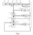
- FIG. 4is a functional block diagram of another embodiment of a secondary circuit including a voltage clamp protection circuit.
- the illustrated inductively coupled systemincludes an inductive power supply 10 and a remote device 20 .
- the inductive power supply 10includes a power supply circuit 12 , a capacitor 14 and a primary coil 16 .
- the remote device 20includes a secondary coil 22 , a thermal cutoff 24 , a voltage clamp 26 , optional thermal adhesive 25 , an optional rectification circuit 32 and a load 34 .
- the voltage clamp protection circuit 38generally includes at least two components, the voltage clamp 26 and the thermal cutoff 24 . In the illustrated embodiment, the voltage clamp 26 and the thermal cutoff 24 are thermally coupled to each other with an optional thermal adhesive 25 .
- the thermal cutoff 24is electrically connected between the secondary coil 22 and the rest of the circuit.
- the voltage clamp 26clamps the input voltage in response to an overvoltage condition. If the overvoltage condition persists for too long the voltage clamp dissipates a sufficient amount of heat to activate the thermal cutoff 24 and create an open circuit that protects the rest of the circuit, in the current embodiment that includes the full bridge rectification circuit 32 and the load 34 .
- the voltage clamp protection circuit 38is particularly suited for use within an inductively coupled system because of some of the challenges and restrictions that inductively coupled systems face. Although the voltage clamp protection circuit 38 is largely described in connection with an inductively coupled system, the voltage clamp protection circuit 38 is suitable to provide some protection for essentially any electrical circuit.
- the voltage clamp protection circuit 38is the sole protection mechanism. In other embodiments, such as those shown in FIGS. 2-4 , the voltage clamp protection circuit 38 may be one of a number of different protection circuits that are used in combination to protect the circuit from various expected and unexpected fault conditions.
- the present inventionis suitable for use with essentially any remote device in any inductively coupled system. Accordingly, the inductive power supply 10 and remote device 20 will not be described in detail. Suffice it to say that the inductive power supply 10 includes power supply circuit 12 and a primary coil 16 and the remote device 20 includes a secondary coil 22 and a secondary load 34 , which could be a battery or essentially any other load.
- the power supply circuit 12generates and applies alternating current to the primary coil 16 .
- the primary coil 16generates an electromagnetic field.
- the power supply circuit 12may be essentially any circuitry capable of supplying alternating current to the primary coil 16 .
- the power supply circuit 12may be the resonant seeking circuit of the inductive power supply system disclosed in U.S. Pat. No. 6,825,620, which is entitled “Inductively Coupled Ballast Circuit” and issued Nov. 30, 2004, to Kuennen et al; the adaptive inductive power supply of U.S. Pat. No. 7,212,414, which is entitled “Adaptive Inductive Power Supply” and issued May 1, 2007, to Baarman; the inductive power supply with communication of U.S. Ser. No. 10/689,148, which is entitled “Adaptive Inductive Power Supply with Communication” and filed on Oct. 20, 2003 to Baarman; the inductive power supply for wirelessly charging a LI-ION battery of U.S. Ser. No.
- the primary coil 16 of the illustrated embodimentis a circular coil of wire suitable for generating an electromagnetic field.
- the primary coil 16may be a coil of Litz wire.
- the characteristics of the coilmay vary from application to application. For example, the number of turns, size, shape and configuration of the coil may vary. Further, the characteristics of the wire may vary, such as length, gauge and type of wire.
- the primary coil 16may alternatively be essentially any structure capable of generating a suitable electromagnetic field.
- the primary coil 16 (or secondary coil 22 )may be replaced by a printed circuit board coil, such as a printed circuit board coil incorporating the inventive principles of U.S. Ser. No. 60/975,953, which is entitled “Printed Circuit Board Coil” and filed on Sep. 28, 2007 by Baarman et al, and which is incorporated herein by reference in its entirety.
- the remote device 20generally includes a secondary coil 22 , voltage clamping protection circuit 38 , an optional rectification circuit 32 and a load 34 .
- the remote device 20is illustrated representatively in the drawings, but it may be essentially any device or component that operates on or otherwise responds to an electromagnetic field.
- the remote device 20may be an active device having a load 34 that operates on electrical power received inductively from the inductive power supply 10 , such as a cell phone, personal digital assistant, digital media player or other electronic device that may use inductive power to recharge an internal battery.
- the optional rectification circuit 32rectifies the power provided to the load.
- the rectification circuit 32may be replaced or deleted.
- the secondary coil 22 of the illustrated embodimentis a circular coil of wire suitable for generating electricity when in the presence of a varying electromagnetic field.
- the secondary coil 22may be a coil of Litz wire.
- the characteristics of the secondary coil 22may vary from application to application. For example, the number of turns, size, shape and configuration of the secondary coil 22 may vary. Further, the characteristics of the wire may vary, such as length, gauge and type of wire.
- the secondary coil 22may alternatively be essentially any structure capable of generating sufficient electrical power in response to an electromagnetic field.
- the voltage clamping protection circuit 38includes two primary components, a voltage clamp 26 and a thermal cutoff 24 .
- the components of the voltage clamping protection circuit 38may be off the shelf components or specifically designed components with a specific set of characteristics for a particular application.
- thermal adhesive 25may be used to thermally couple the voltage clamp 26 and the thermal cutoff 24 .
- the voltage clamp 26 and thermal cutoff 24may be placed in proximity to one another to facilitate sufficient heat transfer.
- the use of thermal adhesive 25may decrease the amount of heat the voltage clamp 26 needs to produce in order to trip the thermal cutoff 24 .
- the resistance of the voltage clamping protection circuit 38is relatively low. For example, in the embodiment illustrated in FIG. 1 , the voltage clamping protection circuit 38 has about 10 milliohms of resistance. Further, no microprocessor control is necessary for operation of the voltage clamping protection circuit 38 .
- the voltage clamp 26clamps the voltage to a desired level and dissipates energy in the form of heat.
- a voltage clamp circuitincludes any electrical circuitry used to prevent another circuit from exceeding a certain predetermined voltage level.
- the voltage clamp 26is capable of dissipating heat sufficient to trip the thermal cutoff without damaging the voltage clamp.
- a voltage clampoperates by sensing the voltage of the monitored circuit and if the voltage threatens to exceed the limit, applies an electric load that draws current from the output in a regulated manner in order to prevent the voltage from exceeding the predetermined voltage level.
- a strict clampis not crucial to the operation of the voltage clamping protection circuit 38 . That is, in many embodiments, the accuracy of the clamp is not a limiting factor to operation of the protection circuit.
- a voltage clampmay operate above or below its rating with a high degree of tolerance without affecting operation of the voltage clamp protection circuit 38 .
- the clamp circuitmay include transition periods where the clamping voltage varies or momentarily departs from its designed characteristics without substantially affecting the performance of the voltage clamping protection circuit 38 . For example, a brief transition period for the voltage clamp once the clamping circuit activates, but before it clamps the voltage is acceptable and does not substantially affect the performance of the protection circuit.
- any voltage clamp 26is suitable for use in the voltage clamp protection circuit 38 .
- the specific type of voltage clamp and its specific characteristicsmay vary from application to application.
- the voltage clamp 26is a single transient voltage suppression (“TVS”) diode.
- a TVS diodeis an electrical component used to protect electronics from voltage spikes.
- the TVS diodeoperates by shunting excess current when the induced voltage exceeds the avalanche breakdown potential. It is a clamping device, suppressing overvoltages above its breakdown voltage. Like most clamping devices, it automatically resets when the overvoltage goes away, but absorbs some of the transient energy internally.
- an off the shelf TVS diodeis thermally coupled to a heatsink in order to dissipate the absorbed transient energy.
- the thermal cutoff 24is thermally coupled to the TVS diode instead of a heatsink.
- the TVS diodemay be thermally coupled to both a heatsink and a thermal cutoff 24 .
- the voltage clamping protection circuitis produced as a single component where the TVS diode is thermally coupled to a thermal cutoff during manufacture.
- the heatsinkmay be removed from an off the shelf voltage clamp and thermally coupled to a thermal cutoff using thermal adhesive. In some applications, thermal coupling may be unnecessary, physical proximity between the voltage clamp and thermal cutoff is sufficient to reliably transfer enough heat from the voltage clamp to the thermal cutoff.
- the TVS diode of the voltage clamp protection circuit illustrated in FIG. 1is bidirectional.
- the bidirectional TVS diodeis connected in parallel with the circuit to be protected, in this embodiment the rectification circuit 32 rectifies the power going to the load 34 .
- the bidirectional TVS diodemay be implemented as a single component or as two opposing avalanche diodes.
- An avalanche diodeis a diode that is designed to go through avalanche breakdown at a specified reverse bias voltage. In some applications, Zener diodes may replace avalanche diodes.
- a bidirectional TVS diodeis merely one example of a voltage clamp suitable for use with the present invention.
- other voltage clampsmay be suitable, such as, for example a metal oxide varistor (“MOV”).
- MOVmetal oxide varistor
- a varistoris an electronic component with a significant non-ohmic current-voltage characteristic. Varistors typically protect circuits against excessive transient voltages by incorporating them into the circuit such that when triggered, they will shunt the current created by the high voltage away from sensitive components. In one embodiment, a sufficient amount of heat is dissipated by a varistor in order to activate a thermal cutoff before the varistor fails.
- a thermal cutoffinterrupts electrical current flow when heated to a specific temperature.
- Thermal cutoffsmay typically be found in heat-producing electrical appliances such as hair dryers and coffeemakers.
- thermal fusesThere are two main categories of thermal cutoffs, thermal fuses and thermal switches.
- a thermal fuseis a cutoff which uses a one-time fusible link.
- a thermal switchsometimes referred to as a thermal reset, is a device which normally opens at a high temperature and re-closes when the temperature drops.
- a thermal cutoffis typically characterized by a trip point temperature.
- the thermal cutoff 24is implemented as a one time thermal fuse with a 102 degrees Celsius trip point.
- the voltage clamp temperature necessary to trigger the thermal cutoffmay depend on a variety of factors including the surface area of the thermal couple between the voltage clamp and thermal cutoff, if any, the proximity between the voltage clamp and the thermal cutoff, the trip point of the thermal cutoff, the temperature of the voltage clamp, the length of time over which the voltage clamp dissipates heat and a number of other various factors.
- the thermal fuseOnce the thermal fuse has been tripped it may be replaced with a new un-tripped fuse making the voltage clamp protection circuit operational again.
- the voltage clamp protection circuitis manufactured as a single replaceable component.
- the thermal cutoffautomatically resets.
- a thermal switchis implemented instead of a one time use thermal fuse.
- the thermal switchincludes a field effect transistor electrically coupled to a thermocouple.
- a thermocoupleis a sensor for measuring temperature. Two dissimilar metals are joined together at one end and when the junction of the two metals is heated or cooled a voltage is produced that can be correlated back to the temperature. Essentially, this allows for conversion of thermal potential difference into electric potential difference. The electric potential difference can be used to control a switch.
- thermocoupleis thermally coupled to the voltage clamp. If the voltage clamp heats the thermocouple past a threshold temperature the thermocouple generates and sends a control signal to the field effect transistor to open the circuit, which relieves the fault condition thereby causing the voltage clamp to cool down. Once the voltage clamp cools down past a threshold temperature, the thermocouple generates and sends a control signal to the field effect transistor to close the circuit.
- the voltage clamp protection circuit described abovemay be used in combination with a variety of other protection circuitry to provide a wide scope of circuit protection for numerous fault conditions, both expected and unexpected.
- three distinct tiers of circuit protectionare provided: 1) an electrical fuse; 2) field effect transistors controlled by a microprocessor in response to one or more sensed characteristics; and 3) a voltage clamp protection circuit.
- additional or fewer protection circuit mechanismsmay be provided.
- the secondary circuitincludes a secondary coil 42 , an electrical fuse 40 , a voltage clamp protection circuit 44 , a power supply rectifier diode 50 , load rectifier diodes 52 , a power supply 56 , a temperature sensor 60 , an input voltage sensor 62 , a coil frequency sensor 84 , a load voltage sensor 64 , a gate voltage boost 68 , a FET control 70 , a load 82 , load disconnect FETs 72 , a current sensor 74 and a microprocessor 80 .
- Additional or fewer componentsmay be included in alternative embodiments.
- alternative embodimentsmay include communication circuitry for communicating with an inductive primary or other remote devices.
- the secondary coil 42 illustrated in FIGS. 2 and 3is in a center tap configuration.
- Center tap configurationrefers to where a connection made to a point along a winding of an inductor. In the current embodiment, the center tap is tied to ground. Alternative embodiments may not use the center tap configuration.
- Electrical fuse 40protects the circuit from large surges.
- the electrical fusemay provide increased protection against overcurrent conditions. However, in some circumstances there may be an overvoltage condition but insufficient current to blow the electrical fuse 40 . In those circumstances, the voltage clamp protection circuit 44 may provide increased circuit protection.
- the voltage clamp protection circuit 44 of FIGS. 2 and 3is described above in connection with the voltage clamp protection circuit 38 of FIG. 1 .
- the voltage clamp protection circuitmay include multiple thermal cutoffs 102 , 104 and voltage clamps 106 , 108 .
- the four devicesmay be thermally connected as one protection device.
- the particular characteristics of the voltage clamp protection circuit 44may vary from application to application.
- the voltage clamps 106 , 108are bidirectional TVS diodes with approximately half the rated clamping voltage of a similarly configured non center tapped design with one voltage clamp.
- the voltage clamp protection circuit 44may include a resistive heating option.
- a resistoris thermally coupled to the thermal cutoff in addition to the voltage clamp. If the microprocessor detects a problem, the resistor may be connected to the coil so that the resistor heats up and trips the thermal cut off.
- the rectifier diode 50rectifies the power from the secondary coil 42 for the power supply 56 and input voltage sensor 62 .
- the load rectifier diodes 52rectify the power for the gate voltage boost 68 , the load 82 and the load voltage sensor 64 . Off the shelf diodes or specifically designed diodes may be implemented.
- the power supply 56 of the embodiments illustrated in FIGS. 2 and 3is a power supply capable of accepting a relatively large voltage and producing an appropriate power source to power the microprocessor 80 and temperature sensor 60 .
- Alternative embodimentsneed not include such a power supply.
- any power supply that is capable of providing a stable power source for the microprocessormay be implemented.
- the temperature sensor 60 , input voltage sensor 62 , coil frequency sensor 84 , current sensor 74 and load voltage sensor 64all sense characteristics about the secondary circuit and provide measurements to the microprocessor.
- the present inventionis suitable for use with essentially any implementation of these sensors. Accordingly, these sensors will not be described in detail.
- a temperature sensor 60provides a temperature reading that may be used for a remote device function, a protection circuit function or both. As long as power supply 56 is operational and providing sufficient power to the temperature sensor 60 and the microprocessor 80 , the temperature sensor may be used as a condition for disconnecting the load 82 . In one embodiment, a simple threshold temperature is set in the microprocessor 80 and if the sensed temperature exceeds the threshold then a control signal is sent to disconnect the load 82 . In other embodiments, a different scheme may be implemented to decide on what condition to disconnect the load 82 . For example, a series of above-threshold temperature readings may trigger the load to disconnect.
- Input voltage sensor 62provides a voltage reading that, in the current embodiment, is primarily used for protecting the circuit. If an overvoltage condition is detected, the microprocessor 80 may send a signal to disconnect the load 82 . In the current embodiment, this protects the load from an overvoltage condition, but does not do anything to protect the rest of the secondary circuit from the overvoltage condition. An overvoltage condition for the load may or may not be considered an overvoltage condition for the rest of the circuit.
- the voltage clamp protection circuit 44 discussed earlieris better suited to handle an overvoltage condition that effects the secondary circuit in general.
- the coil frequency sensor 84provides a frequency reading that may have many different applications, including, for example battery charging algorithms and protection related applications. As with the voltage sensor 62 , any fault conditions determined from the coil frequency sensor 84 of the current embodiment trigger a load disconnect, and do not necessarily protect the other circuitry in the secondary circuit.
- the current sensor 74provides current readings to the microprocessor 80 . In the current embodiment, these readings are useful for both protection functions and charging functions, among other things. As with the other sensors, exceeding a threshold can trigger a control signal to disconnect the load. Because the current sensor 74 is in series with the load 82 , its placement before, as shown in the FIG. 4 embodiment, or after, as shown in the FIGS. 2 and 3 embodiment, the load is irrelevant.
- the load voltage sensor 64 of the current embodimentprovides information to the microprocessor 80 for use in battery charging algorithms.
- the gate voltage boost circuit 68ensures there is sufficient power for the FET control circuit 70 . In embodiments with power supplies that can accept higher voltages, this circuitry ensures the FETs remain operational. In alternative embodiments with other power supplies, the gate voltage boost circuit 68 and the FET control circuit 70 may be unnecessary and may be deleted. For example, in the embodiment illustrated in FIG. 4 the microprocessor 80 connects directly with load disconnect FETs 72 and this circuitry is deleted.
- the load disconnect FETs 72 of the embodiments illustrated in FIGS. 2-4allow the microprocessor to disconnect the load upon detection of a fault condition.
- fault conditionsmay include, but are not limited to, voltage fault conditions, current fault conditions, temperature fault conditions, or frequency fault conditions.
- the load disconnect FETs 72serve to protect the load, but do not satisfy all of the protection needs of the circuit.
- the electrical fuse 40provides relatively quick protection for the entire circuit from large transients.
- the load disconnect FETs 72 in combination with the various sensors and microprocessor 80provide various protection for the load 82 .
- the voltage clamp protection circuit 44provides overvoltage protection for the entire circuit, even where there is not enough current to blow the electrical fuse 40 .
- overvoltage conditionshave been relatively uncommon, but may increase significantly as inductively coupled systems increase in popularity.
Landscapes
- Emergency Protection Circuit Devices (AREA)
- Protection Of Static Devices (AREA)
Abstract
Description
Claims (25)
Priority Applications (1)
| Application Number | Priority Date | Filing Date | Title |
|---|---|---|---|
| US12/428,713US8259428B2 (en) | 2008-04-25 | 2009-04-23 | Input protection circuit |
Applications Claiming Priority (2)
| Application Number | Priority Date | Filing Date | Title |
|---|---|---|---|
| US4803608P | 2008-04-25 | 2008-04-25 | |
| US12/428,713US8259428B2 (en) | 2008-04-25 | 2009-04-23 | Input protection circuit |
Publications (2)
| Publication Number | Publication Date |
|---|---|
| US20090268356A1 US20090268356A1 (en) | 2009-10-29 |
| US8259428B2true US8259428B2 (en) | 2012-09-04 |
Family
ID=40937374
Family Applications (1)
| Application Number | Title | Priority Date | Filing Date |
|---|---|---|---|
| US12/428,713Active2030-03-28US8259428B2 (en) | 2008-04-25 | 2009-04-23 | Input protection circuit |
Country Status (10)
| Country | Link |
|---|---|
| US (1) | US8259428B2 (en) |
| EP (1) | EP2286498A1 (en) |
| JP (1) | JP2011519261A (en) |
| KR (1) | KR20100134133A (en) |
| CN (1) | CN102106053A (en) |
| AU (1) | AU2009240548A1 (en) |
| CA (1) | CA2722362A1 (en) |
| RU (1) | RU2010147857A (en) |
| TW (1) | TW201010232A (en) |
| WO (1) | WO2009132170A1 (en) |
Cited By (22)
| Publication number | Priority date | Publication date | Assignee | Title |
|---|---|---|---|---|
| US20110227551A1 (en)* | 2010-03-22 | 2011-09-22 | PINE VALLEY INVESTMENTS, INC., a Nevada corporation | Mobile wireless communications device including removable electrical power supply module and related methods |
| US20140203771A1 (en)* | 2013-01-18 | 2014-07-24 | Siliconware Precision Industries Co., Ltd. | Electronic package, fabrication method thereof and adhesive compound |
| US9642219B2 (en) | 2014-06-05 | 2017-05-02 | Steelcase Inc. | Environment optimization for space based on presence and activities |
| US9852388B1 (en) | 2014-10-03 | 2017-12-26 | Steelcase, Inc. | Method and system for locating resources and communicating within an enterprise |
| US9921726B1 (en) | 2016-06-03 | 2018-03-20 | Steelcase Inc. | Smart workstation method and system |
| US9940986B2 (en) | 2015-12-16 | 2018-04-10 | Globalfoundries Inc. | Electrostatic discharge protection structures for eFuses |
| US9955318B1 (en) | 2014-06-05 | 2018-04-24 | Steelcase Inc. | Space guidance and management system and method |
| US10161752B1 (en) | 2014-10-03 | 2018-12-25 | Steelcase Inc. | Method and system for locating resources and communicating within an enterprise |
| US20190030983A1 (en)* | 2017-07-28 | 2019-01-31 | Tesla,Inc. | Charging system with thermal protection |
| US10264213B1 (en) | 2016-12-15 | 2019-04-16 | Steelcase Inc. | Content amplification system and method |
| US10353664B2 (en) | 2014-03-07 | 2019-07-16 | Steelcase Inc. | Method and system for facilitating collaboration sessions |
| US10433646B1 (en) | 2014-06-06 | 2019-10-08 | Steelcaase Inc. | Microclimate control systems and methods |
| US10608470B2 (en) | 2012-10-29 | 2020-03-31 | Apple Inc. | Receiver for an inductive power transfer system and a method for controlling the receiver |
| US10614694B1 (en) | 2014-06-06 | 2020-04-07 | Steelcase Inc. | Powered furniture assembly |
| US10733371B1 (en) | 2015-06-02 | 2020-08-04 | Steelcase Inc. | Template based content preparation system for use with a plurality of space types |
| US11063418B2 (en)* | 2018-04-19 | 2021-07-13 | Verily Life Sciences Llc | Systems and methods for overcurrent protection for wireless power receivers |
| US11321643B1 (en) | 2014-03-07 | 2022-05-03 | Steelcase Inc. | Method and system for facilitating collaboration sessions |
| US11532934B2 (en) | 2018-11-29 | 2022-12-20 | Analog Devices International Unlimited Company | Protection device |
| US11744376B2 (en) | 2014-06-06 | 2023-09-05 | Steelcase Inc. | Microclimate control systems and methods |
| US11984739B1 (en) | 2020-07-31 | 2024-05-14 | Steelcase Inc. | Remote power systems, apparatus and methods |
| RU228831U1 (en)* | 2024-05-06 | 2024-09-11 | Акционерное общество "Ульяновское конструкторское бюро приборостроения" (АО "УКБП") | Protection scheme of cascades of radio-electronic devices from transient processes caused by lightning |
| US12118178B1 (en) | 2020-04-08 | 2024-10-15 | Steelcase Inc. | Wayfinding services method and apparatus |
Families Citing this family (12)
| Publication number | Priority date | Publication date | Assignee | Title |
|---|---|---|---|---|
| KR101184461B1 (en)* | 2011-01-10 | 2012-09-19 | 삼성전기주식회사 | Mechanically Commutated Switched reluctance motor |
| US8498088B1 (en) | 2011-12-21 | 2013-07-30 | Western Digital Technologies, Inc. | Storage device with replaceable protection device |
| JP6110294B2 (en)* | 2013-12-27 | 2017-04-05 | ダイキン工業株式会社 | Overvoltage protection circuit and power conversion device including the same |
| CN110571759B (en) | 2014-12-31 | 2021-12-21 | 华为技术有限公司 | A charging protection method and device |
| WO2017201656A1 (en)* | 2016-05-23 | 2017-11-30 | Littelfuse Semiconductor (Wuxi) Co., Ltd. | Transient voltage suppression device with thermal cutoff |
| US20180198272A1 (en)* | 2017-01-12 | 2018-07-12 | Qualcomm Incorporated | Zener Overvoltage Protection (OVP) with a Thermal Trigger |
| CN108599280B (en)* | 2018-05-02 | 2020-04-21 | 华北电力大学 | On-line power taking circuit and system of current limiter in DC transmission system |
| CN108390363B (en)* | 2018-05-02 | 2019-07-02 | 华北电力大学 | Current limiter and device for flexible DC transmission system |
| CN109103866A (en)* | 2018-10-30 | 2018-12-28 | 成都铁达电子股份有限公司 | A kind of Surge Protector |
| CN110492453B (en)* | 2019-09-11 | 2023-01-06 | 阳光电源股份有限公司 | Energy storage system and multistage short-circuit protection system thereof |
| RU197945U1 (en)* | 2020-04-17 | 2020-06-08 | Акционерное общество "Курский электроаппаратный завод" | Thermoelectric protection device for circuit breaker |
| WO2023010342A1 (en)* | 2021-08-04 | 2023-02-09 | Abb Schweiz Ag | Intrinsically safe circuit for load |
Citations (10)
| Publication number | Priority date | Publication date | Assignee | Title |
|---|---|---|---|---|
| US3794898A (en)* | 1973-02-26 | 1974-02-26 | T Gross | Dynamic braking of electric motors with thermistor braking circuit |
| US4866563A (en)* | 1987-09-24 | 1989-09-12 | Semitron Cricklade, Ltd. | Transient suppressor device assembly |
| US5600225A (en)* | 1994-06-30 | 1997-02-04 | Nippon Electric Co | Noncontacting charging device |
| US6016046A (en)* | 1997-07-22 | 2000-01-18 | Sanyo Electric Co., Ltd. | Battery pack |
| US6122157A (en) | 1998-04-27 | 2000-09-19 | Gerlach; Michael J. | Apparatus and method for surge protecting an electrical load connected to an AC power distribution system |
| US6307758B1 (en) | 2000-11-02 | 2001-10-23 | Motorola, Inc. | Transformer secondary disconnect |
| US6553263B1 (en)* | 1999-07-30 | 2003-04-22 | Advanced Bionics Corporation | Implantable pulse generators using rechargeable zero-volt technology lithium-ion batteries |
| US6608470B1 (en) | 1998-01-31 | 2003-08-19 | Motorola, Inc. | Overcharge protection device and methods for lithium based rechargeable batteries |
| JP2006288155A (en) | 2005-04-04 | 2006-10-19 | Canon Inc | Power supply |
| US7242566B2 (en) | 2004-05-25 | 2007-07-10 | Leviton Manufacturing Co., Inc. | Surge protection device |
- 2009
- 2009-04-23USUS12/428,713patent/US8259428B2/enactiveActive
- 2009-04-23JPJP2011506448Apatent/JP2011519261A/enactivePending
- 2009-04-23RURU2010147857/07Apatent/RU2010147857A/ennot_activeApplication Discontinuation
- 2009-04-23KRKR1020107026316Apatent/KR20100134133A/ennot_activeWithdrawn
- 2009-04-23WOPCT/US2009/041505patent/WO2009132170A1/enactiveApplication Filing
- 2009-04-23CNCN2009801249517Apatent/CN102106053A/enactivePending
- 2009-04-23TWTW098113424Apatent/TW201010232A/enunknown
- 2009-04-23EPEP09735270Apatent/EP2286498A1/ennot_activeWithdrawn
- 2009-04-23CACA2722362Apatent/CA2722362A1/ennot_activeAbandoned
- 2009-04-23AUAU2009240548Apatent/AU2009240548A1/ennot_activeAbandoned
Patent Citations (10)
| Publication number | Priority date | Publication date | Assignee | Title |
|---|---|---|---|---|
| US3794898A (en)* | 1973-02-26 | 1974-02-26 | T Gross | Dynamic braking of electric motors with thermistor braking circuit |
| US4866563A (en)* | 1987-09-24 | 1989-09-12 | Semitron Cricklade, Ltd. | Transient suppressor device assembly |
| US5600225A (en)* | 1994-06-30 | 1997-02-04 | Nippon Electric Co | Noncontacting charging device |
| US6016046A (en)* | 1997-07-22 | 2000-01-18 | Sanyo Electric Co., Ltd. | Battery pack |
| US6608470B1 (en) | 1998-01-31 | 2003-08-19 | Motorola, Inc. | Overcharge protection device and methods for lithium based rechargeable batteries |
| US6122157A (en) | 1998-04-27 | 2000-09-19 | Gerlach; Michael J. | Apparatus and method for surge protecting an electrical load connected to an AC power distribution system |
| US6553263B1 (en)* | 1999-07-30 | 2003-04-22 | Advanced Bionics Corporation | Implantable pulse generators using rechargeable zero-volt technology lithium-ion batteries |
| US6307758B1 (en) | 2000-11-02 | 2001-10-23 | Motorola, Inc. | Transformer secondary disconnect |
| US7242566B2 (en) | 2004-05-25 | 2007-07-10 | Leviton Manufacturing Co., Inc. | Surge protection device |
| JP2006288155A (en) | 2005-04-04 | 2006-10-19 | Canon Inc | Power supply |
Non-Patent Citations (4)
| Title |
|---|
| Cantherm, Thermal Links data sheets, 2007. |
| International Search Report and Written Opinion, International Application No. PCT/US2009/041505, International Filing Date Apr. 23, 2009. |
| Littelfuse, Transient Voltage Suppressors data sheets. |
| Panasonic, Thermal Cutoffs (TCO)/Thermal-links data sheets, Feb. 2007. |
Cited By (56)
| Publication number | Priority date | Publication date | Assignee | Title |
|---|---|---|---|---|
| US8791675B2 (en)* | 2010-03-22 | 2014-07-29 | Pine Valley Investments, Inc. | Mobile wireless communications device including removable electrical power supply module and related methods |
| US20110227551A1 (en)* | 2010-03-22 | 2011-09-22 | PINE VALLEY INVESTMENTS, INC., a Nevada corporation | Mobile wireless communications device including removable electrical power supply module and related methods |
| US10608470B2 (en) | 2012-10-29 | 2020-03-31 | Apple Inc. | Receiver for an inductive power transfer system and a method for controlling the receiver |
| US20140203771A1 (en)* | 2013-01-18 | 2014-07-24 | Siliconware Precision Industries Co., Ltd. | Electronic package, fabrication method thereof and adhesive compound |
| US12001976B1 (en) | 2014-03-07 | 2024-06-04 | Steelcase Inc. | Method and system for facilitating collaboration sessions |
| US10353664B2 (en) | 2014-03-07 | 2019-07-16 | Steelcase Inc. | Method and system for facilitating collaboration sessions |
| US11150859B2 (en) | 2014-03-07 | 2021-10-19 | Steelcase Inc. | Method and system for facilitating collaboration sessions |
| US11321643B1 (en) | 2014-03-07 | 2022-05-03 | Steelcase Inc. | Method and system for facilitating collaboration sessions |
| US11402217B1 (en) | 2014-06-05 | 2022-08-02 | Steelcase Inc. | Space guidance and management system and method |
| US9642219B2 (en) | 2014-06-05 | 2017-05-02 | Steelcase Inc. | Environment optimization for space based on presence and activities |
| US12324072B2 (en) | 2014-06-05 | 2025-06-03 | Steelcase Inc. | Environment optimization for space based on presence and activities |
| US11402216B1 (en) | 2014-06-05 | 2022-08-02 | Steelcase Inc. | Space guidance and management system and method |
| US10225707B1 (en) | 2014-06-05 | 2019-03-05 | Steelcase Inc. | Space guidance and management system and method |
| US11212898B2 (en) | 2014-06-05 | 2021-12-28 | Steelcase Inc. | Environment optimization for space based on presence and activities |
| US10057963B2 (en) | 2014-06-05 | 2018-08-21 | Steelcase Inc. | Environment optimization for space based on presence and activities |
| US11979959B1 (en) | 2014-06-05 | 2024-05-07 | Steelcase Inc. | Environment optimization for space based on presence and activities |
| US9955318B1 (en) | 2014-06-05 | 2018-04-24 | Steelcase Inc. | Space guidance and management system and method |
| US10561006B2 (en) | 2014-06-05 | 2020-02-11 | Steelcase Inc. | Environment optimization for space based on presence and activities |
| US12375874B1 (en) | 2014-06-05 | 2025-07-29 | Steelcase Inc. | Space guidance and management system and method |
| US11085771B1 (en) | 2014-06-05 | 2021-08-10 | Steelcase Inc. | Space guidance and management system and method |
| US11307037B1 (en) | 2014-06-05 | 2022-04-19 | Steelcase Inc. | Space guidance and management system and method |
| US11280619B1 (en) | 2014-06-05 | 2022-03-22 | Steelcase Inc. | Space guidance and management system and method |
| US11744376B2 (en) | 2014-06-06 | 2023-09-05 | Steelcase Inc. | Microclimate control systems and methods |
| US10614694B1 (en) | 2014-06-06 | 2020-04-07 | Steelcase Inc. | Powered furniture assembly |
| US10433646B1 (en) | 2014-06-06 | 2019-10-08 | Steelcaase Inc. | Microclimate control systems and methods |
| US11143510B1 (en) | 2014-10-03 | 2021-10-12 | Steelcase Inc. | Method and system for locating resources and communicating within an enterprise |
| US10161752B1 (en) | 2014-10-03 | 2018-12-25 | Steelcase Inc. | Method and system for locating resources and communicating within an enterprise |
| US9852388B1 (en) | 2014-10-03 | 2017-12-26 | Steelcase, Inc. | Method and system for locating resources and communicating within an enterprise |
| US10970662B2 (en) | 2014-10-03 | 2021-04-06 | Steelcase Inc. | Method and system for locating resources and communicating within an enterprise |
| US11168987B2 (en) | 2014-10-03 | 2021-11-09 | Steelcase Inc. | Method and system for locating resources and communicating within an enterprise |
| US11687854B1 (en) | 2014-10-03 | 2023-06-27 | Steelcase Inc. | Method and system for locating resources and communicating within an enterprise |
| US11713969B1 (en) | 2014-10-03 | 2023-08-01 | Steelcase Inc. | Method and system for locating resources and communicating within an enterprise |
| US10121113B1 (en) | 2014-10-03 | 2018-11-06 | Steelcase Inc. | Method and system for locating resources and communicating within an enterprise |
| US10733371B1 (en) | 2015-06-02 | 2020-08-04 | Steelcase Inc. | Template based content preparation system for use with a plurality of space types |
| US11100282B1 (en) | 2015-06-02 | 2021-08-24 | Steelcase Inc. | Template based content preparation system for use with a plurality of space types |
| US9940986B2 (en) | 2015-12-16 | 2018-04-10 | Globalfoundries Inc. | Electrostatic discharge protection structures for eFuses |
| US10459611B1 (en) | 2016-06-03 | 2019-10-29 | Steelcase Inc. | Smart workstation method and system |
| US11330647B2 (en) | 2016-06-03 | 2022-05-10 | Steelcase Inc. | Smart workstation method and system |
| US11956838B1 (en) | 2016-06-03 | 2024-04-09 | Steelcase Inc. | Smart workstation method and system |
| US11690111B1 (en) | 2016-06-03 | 2023-06-27 | Steelcase Inc. | Smart workstation method and system |
| US12213191B1 (en) | 2016-06-03 | 2025-01-28 | Steelcase Inc. | Smart workstation method and system |
| US9921726B1 (en) | 2016-06-03 | 2018-03-20 | Steelcase Inc. | Smart workstation method and system |
| US11652957B1 (en) | 2016-12-15 | 2023-05-16 | Steelcase Inc. | Content amplification system and method |
| US12231810B1 (en) | 2016-12-15 | 2025-02-18 | Steelcase Inc. | Content amplification system and method |
| US11190731B1 (en) | 2016-12-15 | 2021-11-30 | Steelcase Inc. | Content amplification system and method |
| US10264213B1 (en) | 2016-12-15 | 2019-04-16 | Steelcase Inc. | Content amplification system and method |
| US10638090B1 (en) | 2016-12-15 | 2020-04-28 | Steelcase Inc. | Content amplification system and method |
| US10897598B1 (en) | 2016-12-15 | 2021-01-19 | Steelcase Inc. | Content amplification system and method |
| US11225156B2 (en)* | 2017-07-28 | 2022-01-18 | Tesla, Inc. | Charging system with thermal protection |
| US20190030983A1 (en)* | 2017-07-28 | 2019-01-31 | Tesla,Inc. | Charging system with thermal protection |
| US11063418B2 (en)* | 2018-04-19 | 2021-07-13 | Verily Life Sciences Llc | Systems and methods for overcurrent protection for wireless power receivers |
| US11532934B2 (en) | 2018-11-29 | 2022-12-20 | Analog Devices International Unlimited Company | Protection device |
| US12118178B1 (en) | 2020-04-08 | 2024-10-15 | Steelcase Inc. | Wayfinding services method and apparatus |
| US11984739B1 (en) | 2020-07-31 | 2024-05-14 | Steelcase Inc. | Remote power systems, apparatus and methods |
| US12341360B1 (en) | 2020-07-31 | 2025-06-24 | Steelcase Inc. | Remote power systems, apparatus and methods |
| RU228831U1 (en)* | 2024-05-06 | 2024-09-11 | Акционерное общество "Ульяновское конструкторское бюро приборостроения" (АО "УКБП") | Protection scheme of cascades of radio-electronic devices from transient processes caused by lightning |
Also Published As
| Publication number | Publication date |
|---|---|
| CN102106053A (en) | 2011-06-22 |
| AU2009240548A1 (en) | 2009-10-29 |
| TW201010232A (en) | 2010-03-01 |
| RU2010147857A (en) | 2012-05-27 |
| US20090268356A1 (en) | 2009-10-29 |
| WO2009132170A1 (en) | 2009-10-29 |
| AU2009240548A2 (en) | 2010-12-09 |
| CA2722362A1 (en) | 2009-10-29 |
| JP2011519261A (en) | 2011-06-30 |
| EP2286498A1 (en) | 2011-02-23 |
| KR20100134133A (en) | 2010-12-22 |
Similar Documents
| Publication | Publication Date | Title |
|---|---|---|
| US8259428B2 (en) | Input protection circuit | |
| EP2605355B1 (en) | Intrinsically safe energy limiting circuit | |
| US8786995B2 (en) | Surge current suppressing circuit | |
| EP2051359B1 (en) | Power supply circuit and earth leakage circuit breaker using the same | |
| EP3920362B1 (en) | Charging circuit and electronic device | |
| JPWO2004017507A1 (en) | Overheat protection device | |
| US20110267732A1 (en) | Circuit protective device | |
| CN101350516A (en) | Circuit and method for protecting energy storage device | |
| CN102246373A (en) | Overload protection of a voltage reduction device | |
| CN103490376B (en) | For the over-and under-voltage protective device of single-phase source system | |
| JP4265614B2 (en) | Secondary power receiving circuit for contactless power supply equipment | |
| US20170134017A1 (en) | Overcurrent protection circuit | |
| CN207732635U (en) | A kind of Switching Power Supply of anti-lightning surge | |
| JP4328860B2 (en) | Fault current limiter and power system using the same | |
| CN103701100A (en) | Switching power supply and over-voltage protection circuit thereof | |
| AU2010100724A4 (en) | An electronic fault protection circuit | |
| TW202023138A (en) | Alternating current circuit protection device | |
| CN209358231U (en) | a surge protector | |
| JP6808764B2 (en) | Power supply device for protective relay | |
| KR100483930B1 (en) | Inrush Current Fault Function Prevention Circuit for Over Load Breaker | |
| JP7160655B2 (en) | transformer | |
| KR100483932B1 (en) | Over Load Breaker having Sensitivity Adjustment Function | |
| EP3080829B1 (en) | Electrical switching apparatus including transductor circuit and alternating current electronic trip circuit | |
| KR100713341B1 (en) | Circuit protection device with constant voltage holding and overcurrent blocking | |
| CN102340134A (en) | Circuit system protection device |
Legal Events
| Date | Code | Title | Description |
|---|---|---|---|
| AS | Assignment | Owner name:ACCESS BUSINESS GROUP INTERNATIONAL LLC, MICHIGAN Free format text:ASSIGNMENT OF ASSIGNORS INTEREST;ASSIGNORS:MOLLEMA, SCOTT A.;BAARMAN, DAVID W.;ZEIK, ANDREW C.;AND OTHERS;REEL/FRAME:022587/0457;SIGNING DATES FROM 20090413 TO 20090420 Owner name:ACCESS BUSINESS GROUP INTERNATIONAL LLC, MICHIGAN Free format text:ASSIGNMENT OF ASSIGNORS INTEREST;ASSIGNORS:MOLLEMA, SCOTT A.;BAARMAN, DAVID W.;ZEIK, ANDREW C.;AND OTHERS;SIGNING DATES FROM 20090413 TO 20090420;REEL/FRAME:022587/0457 | |
| FEPP | Fee payment procedure | Free format text:PAYOR NUMBER ASSIGNED (ORIGINAL EVENT CODE: ASPN); ENTITY STATUS OF PATENT OWNER: LARGE ENTITY | |
| STCF | Information on status: patent grant | Free format text:PATENTED CASE | |
| FPAY | Fee payment | Year of fee payment:4 | |
| AS | Assignment | Owner name:PHILIPS IP VENTURES B.V., NETHERLANDS Free format text:ASSIGNMENT OF ASSIGNORS INTEREST;ASSIGNOR:ACCESS BUSINESS GROUP INTERNATIONAL LLC;REEL/FRAME:045644/0810 Effective date:20171020 | |
| MAFP | Maintenance fee payment | Free format text:PAYMENT OF MAINTENANCE FEE, 8TH YEAR, LARGE ENTITY (ORIGINAL EVENT CODE: M1552); ENTITY STATUS OF PATENT OWNER: LARGE ENTITY Year of fee payment:8 | |
| MAFP | Maintenance fee payment | Free format text:PAYMENT OF MAINTENANCE FEE, 12TH YEAR, LARGE ENTITY (ORIGINAL EVENT CODE: M1553); ENTITY STATUS OF PATENT OWNER: LARGE ENTITY Year of fee payment:12 |