US8259409B2 - Spin torque oscillator sensor - Google Patents
Spin torque oscillator sensorDownload PDFInfo
- Publication number
- US8259409B2 US8259409B2US12/492,050US49205009AUS8259409B2US 8259409 B2US8259409 B2US 8259409B2US 49205009 AUS49205009 AUS 49205009AUS 8259409 B2US8259409 B2US 8259409B2
- Authority
- US
- United States
- Prior art keywords
- sensor
- magnetic
- layer
- oscillation
- magnetization
- Prior art date
- Legal status (The legal status is an assumption and is not a legal conclusion. Google has not performed a legal analysis and makes no representation as to the accuracy of the status listed.)
- Active, expires
Links
Images


Classifications
- G—PHYSICS
- G01—MEASURING; TESTING
- G01R—MEASURING ELECTRIC VARIABLES; MEASURING MAGNETIC VARIABLES
- G01R33/00—Arrangements or instruments for measuring magnetic variables
- G01R33/12—Measuring magnetic properties of articles or specimens of solids or fluids
- G01R33/1284—Spin resolved measurements; Influencing spins during measurements, e.g. in spintronics devices
- B—PERFORMING OPERATIONS; TRANSPORTING
- B82—NANOTECHNOLOGY
- B82Y—SPECIFIC USES OR APPLICATIONS OF NANOSTRUCTURES; MEASUREMENT OR ANALYSIS OF NANOSTRUCTURES; MANUFACTURE OR TREATMENT OF NANOSTRUCTURES
- B82Y25/00—Nanomagnetism, e.g. magnetoimpedance, anisotropic magnetoresistance, giant magnetoresistance or tunneling magnetoresistance
- G—PHYSICS
- G01—MEASURING; TESTING
- G01R—MEASURING ELECTRIC VARIABLES; MEASURING MAGNETIC VARIABLES
- G01R33/00—Arrangements or instruments for measuring magnetic variables
- G01R33/02—Measuring direction or magnitude of magnetic fields or magnetic flux
- G01R33/06—Measuring direction or magnitude of magnetic fields or magnetic flux using galvano-magnetic devices
- G01R33/09—Magnetoresistive devices
- G01R33/093—Magnetoresistive devices using multilayer structures, e.g. giant magnetoresistance sensors
- G—PHYSICS
- G11—INFORMATION STORAGE
- G11B—INFORMATION STORAGE BASED ON RELATIVE MOVEMENT BETWEEN RECORD CARRIER AND TRANSDUCER
- G11B5/00—Recording by magnetisation or demagnetisation of a record carrier; Reproducing by magnetic means; Record carriers therefor
- G11B5/127—Structure or manufacture of heads, e.g. inductive
- G11B5/33—Structure or manufacture of flux-sensitive heads, i.e. for reproduction only; Combination of such heads with means for recording or erasing only
- G11B5/39—Structure or manufacture of flux-sensitive heads, i.e. for reproduction only; Combination of such heads with means for recording or erasing only using magneto-resistive devices or effects
- G11B5/3903—Structure or manufacture of flux-sensitive heads, i.e. for reproduction only; Combination of such heads with means for recording or erasing only using magneto-resistive devices or effects using magnetic thin film layers or their effects, the films being part of integrated structures
- H—ELECTRICITY
- H01—ELECTRIC ELEMENTS
- H01F—MAGNETS; INDUCTANCES; TRANSFORMERS; SELECTION OF MATERIALS FOR THEIR MAGNETIC PROPERTIES
- H01F10/00—Thin magnetic films, e.g. of one-domain structure
- H01F10/32—Spin-exchange-coupled multilayers, e.g. nanostructured superlattices
- H01F10/324—Exchange coupling of magnetic film pairs via a very thin non-magnetic spacer, e.g. by exchange with conduction electrons of the spacer
- H01F10/3254—Exchange coupling of magnetic film pairs via a very thin non-magnetic spacer, e.g. by exchange with conduction electrons of the spacer the spacer being semiconducting or insulating, e.g. for spin tunnel junction [STJ]
- H—ELECTRICITY
- H01—ELECTRIC ELEMENTS
- H01F—MAGNETS; INDUCTANCES; TRANSFORMERS; SELECTION OF MATERIALS FOR THEIR MAGNETIC PROPERTIES
- H01F10/00—Thin magnetic films, e.g. of one-domain structure
- H01F10/32—Spin-exchange-coupled multilayers, e.g. nanostructured superlattices
- H01F10/324—Exchange coupling of magnetic film pairs via a very thin non-magnetic spacer, e.g. by exchange with conduction electrons of the spacer
- H01F10/3268—Exchange coupling of magnetic film pairs via a very thin non-magnetic spacer, e.g. by exchange with conduction electrons of the spacer the exchange coupling being asymmetric, e.g. by use of additional pinning, by using antiferromagnetic or ferromagnetic coupling interface, i.e. so-called spin-valve [SV] structure, e.g. NiFe/Cu/NiFe/FeMn
- H—ELECTRICITY
- H01—ELECTRIC ELEMENTS
- H01F—MAGNETS; INDUCTANCES; TRANSFORMERS; SELECTION OF MATERIALS FOR THEIR MAGNETIC PROPERTIES
- H01F10/00—Thin magnetic films, e.g. of one-domain structure
- H01F10/32—Spin-exchange-coupled multilayers, e.g. nanostructured superlattices
- H01F10/324—Exchange coupling of magnetic film pairs via a very thin non-magnetic spacer, e.g. by exchange with conduction electrons of the spacer
- H01F10/3286—Spin-exchange coupled multilayers having at least one layer with perpendicular magnetic anisotropy
- H—ELECTRICITY
- H01—ELECTRIC ELEMENTS
- H01F—MAGNETS; INDUCTANCES; TRANSFORMERS; SELECTION OF MATERIALS FOR THEIR MAGNETIC PROPERTIES
- H01F10/00—Thin magnetic films, e.g. of one-domain structure
- H01F10/32—Spin-exchange-coupled multilayers, e.g. nanostructured superlattices
- H01F10/324—Exchange coupling of magnetic film pairs via a very thin non-magnetic spacer, e.g. by exchange with conduction electrons of the spacer
- H01F10/329—Spin-exchange coupled multilayers wherein the magnetisation of the free layer is switched by a spin-polarised current, e.g. spin torque effect
- H—ELECTRICITY
- H10—SEMICONDUCTOR DEVICES; ELECTRIC SOLID-STATE DEVICES NOT OTHERWISE PROVIDED FOR
- H10N—ELECTRIC SOLID-STATE DEVICES NOT OTHERWISE PROVIDED FOR
- H10N50/00—Galvanomagnetic devices
- H10N50/10—Magnetoresistive devices
- G—PHYSICS
- G11—INFORMATION STORAGE
- G11B—INFORMATION STORAGE BASED ON RELATIVE MOVEMENT BETWEEN RECORD CARRIER AND TRANSDUCER
- G11B5/00—Recording by magnetisation or demagnetisation of a record carrier; Reproducing by magnetic means; Record carriers therefor
- G11B2005/0002—Special dispositions or recording techniques
- G11B2005/0005—Arrangements, methods or circuits
- G11B2005/001—Controlling recording characteristics of record carriers or transducing characteristics of transducers by means not being part of their structure
- G11B2005/0013—Controlling recording characteristics of record carriers or transducing characteristics of transducers by means not being part of their structure of transducers, e.g. linearisation, equalisation
- G11B2005/0016—Controlling recording characteristics of record carriers or transducing characteristics of transducers by means not being part of their structure of transducers, e.g. linearisation, equalisation of magnetoresistive transducers
Definitions
- the present inventionrelates to magnetic heads for data recording, and more particularly to a sensor that uses spin torque induced magnetic oscillation variation to detect a magnetic field.
- the heart of a computer's long term memoryis an assembly that is referred to as a magnetic hard disk drive.
- the magnetic hard disk driveincludes a rotating magnetic disk, write and read heads that are suspended by a suspension arm adjacent to a surface of the rotating magnetic disk and an actuator that swings the suspension arm to place the read and write heads over selected circular tracks on the rotating disk.
- the read and write headsare directly located on a slider that has an air bearing surface (ABS).
- ABSair bearing surface
- the suspension armbiases the slider toward the surface of the disk, and when the disk rotates, air adjacent to the disk moves along with the surface of the disk.
- the sliderflies over the surface of the disk on a cushion of this moving air.
- the write and read headsare employed for writing magnetic transitions to and reading magnetic transitions from the rotating disk.
- the read and write headsare connected to processing circuitry that operates according to a computer program to implement the writing and reading functions.
- the write headhas traditionally included a coil that passes through a magnetic yoke that includes a write pole and a return pole.
- Current conducted to the coil layerinduces a magnetic flux in the pole pieces which causes a write field to emit from the write pole for the purpose of writing a magnetic transition in tracks on the moving media, such as in circular tracks on the rotating disk.
- a sensorsuch as a GMR or TMR sensor has been employed for sensing magnetic fields from the rotating magnetic disk.
- Such sensorsuse a spin valve magnetic design, including a nonmagnetic conductive spacer layer, or nonmagnetic insulating barrier layer, sandwiched between first and second ferromagnetic layers, referred to as a pinned or reference layer and a free layer.
- First and second leadsare connected to the sensor for conducting a sense current there-through.
- the magnetization of the pinned layeris pinned perpendicular to the air bearing surface (ABS) and the magnetic moment of the free layer is located parallel to the ABS, but free to rotate in response to external magnetic fields.
- the magnetization of the pinned layeris typically pinned by exchange coupling with an antiferromagnetic layer.
- magnetoresistive sensorsIn order to increase data density, manufacturers always strive to decrease the size of magnetoresistive sensors. For example, decreasing the track width of the sensor to fit more data tracks on the disk and decreasing the gap thickness of the sensor to increase linear data density.
- spin valve sensorsAs spin valve sensors become ever smaller they reach a point where sensor instability and noise make the sensors impractical to achieve sufficiently high signal to noise over the required bandwidth for recording.
- magnetic noiseresulting from the fluctuations of the ferromagnetic layers caused by temperature, can decrease the signal to noise ratio of a very small sensor to the point that such as sensor cannot effectively be used to read a signal with sufficient certainty.
- an additional noise resulting from shot noisefurther increases the noise, thereby decreasing the overall signal to noise and making MTJ sensors unsuitable for ultra high density recording. Therefore, there is a continuing need for a sensor design that can be made very small for reading at very high data densities.
- the present inventionprovides a spin torque oscillation magnetoresistive sensor for measuring a magnetic field.
- the sensoruses a change in precessional oscillation frequency of a magnetization of a magnetic layer to detect the presence of a magnetic field.
- the sensorcan include a magnetic free layer, a magnetic pinned layer and a non-magnetic layer sandwiched therebetween. Circuitry is connected with these layers to induce an electrical current through the layers. Electrons that become spin polarized by traveling through one ferromagnetic layer and then pass into a second ferromagnetic layer can induce a spin torque acting upon the second ferromagnetic layer that can drive that layer's magnetization into a persistent precessional state.
- the oscillation of one ferromagnetic layer with respect to the othercauses time-varying resistance changes through magnetoresistance mechanisms such as giant magnetoresistance (GMR), tunneling magnetoresistance (TMR), current perpendicular to the plane GMR (CPP-GMR) or anisotropic magnetoresistance (AMR). As the frequency of these oscillations modulate in response to a magnetic field, this modulation of the oscillation frequency can be measured to detect the presence of the magnetic field.
- GMRgiant magnetoresistance
- TMRtunneling magnetoresistance
- the present inventioncan also include a multi-sensor array in which a plurality of individual sensor elements are arranged in an array and are connected to common leads.
- the individual sensor elementscan be constructed so that they have different natural oscillation frequencies. Because these natural frequencies are different, the circuitry connected with the sensors can be constructed to distinguish the signals from the various individual sensors even if they are connected with the circuitry via a common lead.
- Thisadvantageously allows a single pair of leads to be used for a plurality of sensor elements, saving immense space on the head and making such a multi-sensor array manufacturable and practical.
- This use of common lead layerswould not be possible using a conventional sensor such as a GMR or TMR sensor, because it would be impossible to distinguish the signals from the individual sensor elements.
- providing individual source and drain leads for each sensoris not practical because in the small volume required for parallel detection of small recording bits there is insufficient room to place and route the leads.
- the individual sensor elementscan be connected in parallel or in series, or both.
- the use of such a multi-sensor arrayadvantageously allows for greatly increased data density, because it makes it possible to read and cancel out signals from adjacent data. This can be used to greatly decrease signal noise or supply a position error signal to help maintain proper positioning of the head.
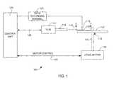
- FIG. 1is a schematic illustration of a disk drive system in which the invention might be embodied
- FIG. 2is an ABS view of a slider, taken from line 2 - 2 of FIG. 1 , illustrating the location of a magnetic head thereon;
- FIG. 3is a schematic ABS view of a sensor according to an embodiment of the invention.
- FIG. 4is a schematic side cross sectional view of the sensor of FIG. 3 ;
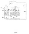
- FIG. 5is a schematic ABS view of a sensor design according to another possible embodiment of the invention.
- FIG. 6is a schematic ABS view of a sensor design according to yet another possible embodiment of the invention.
- FIG. 7is a simulated time domain graph of free layer magnetization vs. time for a typical spin valve structure with the application of a constant magnetic field
- FIG. 8is a frequency domain graph of free layer magnetization vs. time transformed from FIG. 7 ;
- FIG. 9is a graph showing the simulated response of the free layer magnetization oscillation to variations in external magnetic field amplitude for the same structure shown in FIGS. 7 and 8 .
- FIG. 1there is shown a disk drive 100 embodying this invention.
- at least one rotatable magnetic disk 112is supported on a spindle 114 and rotated by a disk drive motor 118 .
- the magnetic recording on each diskis in the form of annular patterns of concentric data tracks (not shown) on the magnetic disk 112 .
- At least one slider 113is positioned near the magnetic disk 112 , each slider 113 supporting one or more magnetic head assemblies 121 . As the magnetic disk rotates, slider 113 moves radially in and out over the disk surface 122 so that the magnetic head assembly 121 may access different tracks of the magnetic disk where desired data are written.
- Each slider 113is attached to an actuator arm 119 by way of a suspension 115 .
- the suspension 115provides a slight spring force which biases slider 113 against the disk surface 122 .
- Each actuator arm 119is attached to an actuator means 127 .
- the actuator means 127 as shown in FIG. 1may be a voice coil motor (VCM).
- the VCMcomprises a coil movable within a fixed magnetic field, the direction and speed of the coil movements being controlled by the motor current signals supplied by controller 129 .
- the rotation of the magnetic disk 112generates an air bearing between the slider 113 and the disk surface 122 which exerts a force on the slider.
- the air bearingthus counter-balances the slight spring force of suspension 115 and supports the slider 113 off and slightly above the disk surface by a small, substantially constant spacing during normal operation.
- control unit 129The various components of the disk storage system are controlled in operation by control signals generated by control unit 129 , such as access control signals and internal clock signals.
- control unit 129comprises logic control circuits, storage means and a microprocessor.
- the control unit 129generates control signals to control various system operations such as drive motor control signals on line 123 and head position and seek control signals on line 128 .
- the control signals on line 128provide the desired current profiles to optimally move and position slider 113 to the desired data track on disk 112 .
- Write and read signalsare communicated to and from write and read heads 121 by way of recording channel 125 .
- FIG. 2is an ABS view of the slider 113 , and as can be seen the magnetic head including an inductive write head and a read sensor, is located at a trailing edge of the slider.
- the magnetic head including an inductive write head and a read sensoris located at a trailing edge of the slider.
- FIGS. 3 and 4a magnetoresistive sensor 302 is shown that can take advantage of spin torque oscillations to sense a localized magnetic field.
- FIG. 3shows the sensor 302 as viewed from the air bearing surface (ABS).
- FIG. 4shows a side cross sectional view of the sensor 302 and also shows a magnetic medium 402 with recorded magnetic transitions of “bits” 404 .
- the magnetoresistive sensorincludes a sensor stack 304 that is sandwiched between first and second magnetic shields 306 , 308 that can be made of an electrically conductive, magnetic material such as NiFe so that they can function as electrical leads as well as magnetic shields.
- the sensor stackincludes a pinned layer structure 310 , a free layer 312 and a non-magnetic layer 314 sandwiched between the free layer 312 and the pinned layer structure 310 .
- the non-magnetic layer 314can be a non-magnetic, electrically conducting spacer layer such as Cu or could be a thin, non-magnetic, electrically insulating barrier layer.
- a capping layer 328such as Ta can be formed over the top of the sensor stack 304 .
- the pinned layer structurecan include a magnetic pinned layer 316 , a reference layer 318 and a non-magnetic antiparallel coupling layer 320 sandwiched between the pinned layer 316 and the reference layer 318 .
- the pinned and reference layers 316 , 318can be constructed of a material such as CoFe and the antiparallel coupling layer 320 can be constructed of a material such as Ru having a thickness of about 10 Angstroms.
- the pinned magnetic layer 316can be exchange coupled with a layer of antiferromagnetic material AFM layer 322 , which can be a material such as IrMn, PtMn or some other suitable antiferromagnetic material.
- the free layer 312has a magnetization that is biased generally parallel with the ABS as indicated by arrow 330 .
- Biasingcan be provided by first and second hard magnetic bias layers 332 , 334 that can be arranged at either side of the sensor stack 304 .
- the bias layers 332 , 334are separated from the sensor stack 304 and from at least one of the leads 306 by insulation layers 336 .
- the spin of the electrons flowing through the reference layer 318are polarized by the magnetization 326 of the reference layer 318 .
- These polarized electronscan then apply a torque to the free layer magnetization 312 , generating spin waves that result in chaotic magnetization dynamics (noise) or collective excitations (oscillations), depending on various parameters of the system such as sensor shape, anisotropy, layer materials and thicknesses, and applied currents and magnetic fields.
- spin torque oscillationshave been considered as possible sources of microwaves for communication applications as discussed by J. C. Slonczewski, JMMM 159, L1 1996. These oscillations involve spin torque excited precession of the magnetization along the equilibrium axis of the ferromagnet. For example, with reference to FIGS. 3 and 4 , the precession, or oscillation of the magnetization 330 is indicated by arrow 338 .
- the pinned layer magnetizationis constrained by exchange anisotropy to an antiferromagnetic layer, it is possible for the magnetization of the pinned layer to also oscillate and contribute to the sensor signal when the applied current densities are high enough to generate spin torque excitations in the pinned layer.
- the sensor 302is connected via leads 340 , 342 to processing circuitry 344 .
- the leads 340 , 342can be connected with the shield/lead layers 306 , 308 , such that one lead 340 is connected with one lead/shield layer 308 , while the other lead 342 is connected with the other lead/shield layer 306 .
- the processing circuitry 344sends a sense current through the sensor stack 304 , and also measures the electrical resistance across the sensor stack 304 .
- the electrical resistance across the spacer or barrier layer 314changes as the orientation of magnetization 330 of the free layer changes 312 relative to the magnetization 326 of the reference layer 316 . The closer these magnetizations 330 , 326 are to being parallel the lower the electrical resistance will be. Conversely, the closer these magnetizations 330 , 326 are to being anti-parallel the higher the electrical resistance will be.
- the magnetic transitions 404 of the magnetic medium 402cause the above described change in the frequency of the oscillation 338 of the magnetization 330 .
- the frequency of this oscillationcan be measured by the circuitry 344 by measuring the change of electrical resistance across the sensor stack 304 . Therefore, the spin torque oscillation that was previously a major contributor to signal noise and a limiting factor in the reduction of sensor size for a standard GMR or TMR sensor is now advantageously utilized to measure the presence of a magnetic field at extremely small bit sizes.
- a 50 mT swing in field from the transition 404 in the magnetic medium 402would result in an oscillation 338 frequency shift of 10 GHz, from 15 GHz to 25 GHz.
- the spin torque oscillatorwould precess approximately 15 times over as the sensor passes over a recorded bit of one polarity and 25 times as the sensor passes over a recorded bit of the opposite polarity.
- the signal and signal to noise ratio for the spin torque oscillator 302can be compared to a similar sensor operated as in conventional GMR mode. It can be assumed that the amount of Additive White Gaussian Noise (AWGN) and peak to peak signal amplitude can stay the same. One can expect a 6 dB signal to noise ratio advantage purely from the greater efficiency of the spin torque oscillator 302 as compared with a conventional GMR sensor.
- AWGNAdditive White Gaussian Noise
- the spin torque oscillatoris swept across a range of frequencies greater than the bandwidth of the flux signal itself.
- This wideband modulation of the STO by the fluxmakes the system more robust to perturbations due to Johnson noise and magnetic noise.
- the STOis swept across at least a bandwidth of Fb/ ⁇ , where Fb is the data rate of the system, the net head and electronics noise in the demodulated signal will be smaller than the noise due to the same sources in a conventional GMR sensor of similar design.
- the modulation of the STOincreases further, the net head and electronics noise in the demodulated signal decreases.
- the modulation depthdefined as the ratio of the frequency range to the maximum frequency
- the bandwidth of the signal at the input to the phase detectormust be correspondingly increased and thus the SNR at the input to the phase detector decreases.
- noise at the input to the phase detectormay be sufficient to change the sign of the signal. This sign change is interpreted by the phase detector as a 180 degree phase change and produces a very large noise pulse at the output of the phase detector.
- the noise power at the input to the phase detectormust be maintained at least 5 times smaller than the signal power in order to keep the probability that the sign will change smaller than 1e-6.
- the modulation of the STOwill be sufficient to ensure that the effects of Johnson noise and magnetic noise are negligibly small compared to phase noise in the STO, while not being so great as to allow noise to flip the signal polarity at the input to the phase detector.
- T50refers to the time required for the flux to rise from the 25% to 75% of it's full range and T refers to the time required to read or write a bit.
- the mean square difference between the two read signals using the spin torque oscillatoris about 4 times as great as the mean square difference between the read signals using the conventional GMR sensor.
- the signal to noise ratio of prior art GMR sensorshas been in the range of about 27 to 33 dB. Sensor SNR requirements are likely to remain this high or even increase to 35 dB as recording enters the TB/in 2 regime.
- the base-to-peak signal poweris determined by the amount of frequency modulation one can expect from the maximum media field.
- the noise poweris determined from the mean-squared fluctuation in the frequency.
- the FWHMis approximately 2.35 sigma and a 30 dB signal to noise ratio would roughly correspond to a line width to modulation depth ratio of about 13:1, while 40 dB would correspond to a ratio of 42:1.
- phase noisecontributing to spectral line width, both arising from thermal fluctuations: these are fluctuations along and perpendicular to the motion of the spin (velocity noise and angle noise).
- ⁇ f L(4 ⁇ k B Tn 2 )/(M s VD 2 ), where ⁇ is the gyromagnetic ratio, ⁇ is the Gilbert damping parameter, K B is Boltzmann's constant, M s is the magnetization, V is the volume, D is the degree of precession on the unit sphere, and n is the mode index. For typical materials at room temperature, this is about 24 MHz, much less than the line width required to achieve high SNR if the STO modulation depth is 5-10 GHz.
- the energy of the systemcan be estimated as E( ⁇ ) ⁇ K M s V(sin ⁇ ) 2 , where ⁇ is the angle at which the magnetization rotates from its equilibrium position, which is not exactly a fluctuation from the precession orbit, but close enough for this estimate, M s is the magnetization and K is the anisotropy.
- ⁇is the angle at which the magnetization rotates from its equilibrium position, which is not exactly a fluctuation from the precession orbit, but close enough for this estimate
- M sis the magnetization
- Kis the anisotropy.
- the noise power from the mag-noiseis: P magnoise ⁇ k B TPR P ( ⁇ R/R) 2 ⁇ /H stiff 2 ⁇ M s D 2 T free , where k B is Boltzmann's constant, T is temperature, P is the power dissipated by the sensor, R p is the sensor resistance, ⁇ R/R is the magnetoresistance, ⁇ is the Gilbert damping constant, H stiff is the stiffness field of the sensor (including uniaxial and shape anisotropies), ⁇ is the gyromagnetic ratio, M s is the saturation magnetization, D is one side of the sensor, and t free is the free layer thickness.
- k BBoltzmann's constant
- Ttemperature
- Pthe power dissipated by the sensor
- R pthe sensor resistance
- ⁇ R/Rthe magnetoresistance
- ⁇the Gilbert damping constant
- H stiffthe stiffness field of the sensor (including uniaxial and shape anisotropies)
- M sis
- FIGS. 7 and 8illustrate how spin torque can excite steady state magnetization precession.
- the graphs of FIGS. 7 and 8simulate a 40 nm by 120 nm by 5 nm thick elliptical nanomagnet under the influence of spin torque exerted by a spin polarized current with a current density of 5E7 A/cm 2 and a time-invariant 100 Oe magnetic field oriented along the long axis of the ellipse.
- a steady state precessionis reached which, when fast Fourier transformed, exhibits the clear spectral peaks at well defined frequencies shown in FIG. 8 .
- the DC field of the above exampleis replaced by an AC magnetic field (400 Oe peak-to-peak) to model the response of a spin torque oscillation sensor excited by hard drive media.
- the precessing layeris assumed to have an anisotropy field of 1000 Oe.
- persistent magnetization oscillationscan be generated for excitation fields typical of magnetic media.
- the natural frequency of these oscillations(on the order of 10 GHzs or larger) are much higher than the 500 MHz AC field frequency, achieving a significant number of measurement cycles in one data period is not an issue.
- FIGS. 4 and 5show a magnetic configuration in which the magnetic sublayers of the antiparallel pinned reference layer are oriented substantially perpendicular to the free layer in the absence of a magnetic field and the external magnetic field to be sensed is substantially along the axis of the reference layer.
- Many other magnetic configurations in which sustainable oscillations with significant frequency shift with field are possibleincluding configurations in which the angle between the free layer and reference layer are not 90 degrees, and in which the magnetic field to be sensed is applied at an angle with respect to the reference and free layers.
- configurations in which the magnetization of all layersare co-linear in zero field and the field is applied either along the co-linear axis or perpendicular to it will also yield operable devices.
- FIG. 5illustrates another embodiment of the invention.
- Adjacent track interferenceposes a serious challenge to the reading of data tracks at very high data densities (e.g. at very small track widths).
- One way to address this challengeis to construct a multi-sensor, wherein a central sensor reads the desired track and first and second sensors at either side of the central sensor are used to read adjacent tack signals so that those signals can be cancelled out.
- the side sensorsmust be very close to the central primary sensor.
- a conventional sensorsuch as a GMR or TMR sensor
- separate lead structuresmust be provided for each of the sensors. This makes the use of such a multi-sensor structure impractical in a functional read head.
- Lithographic patterning limitationslimit die amount by which size and spacing of these leads can be reduced.
- the amount of available space (real estate) on a headis limited, such that the various leads for each of these sensors cannot fit onto the head.
- a multilayer sensor structure 502includes multiple sensor stacks 504 , 506 , 508 .
- the sensor structure 502is shown in FIG. 5 as viewed in a plane that is parallel with the air bearing surface (ABS). Therefore, the sensor structure 502 can include a central, primary sensor stack 506 that is used to read a desired data track.
- the structure 502also includes first and second side sensors 504 , 508 that can be used to sense adjacent data tracks.
- the sensor stacks 504 , 506 , 508can be separated by narrow gaps 510 , 512 that can be filled with a non-magnetic insulating material such as alumina.
- the sensor structurealso includes first and second leads 514 , 516 that can be constructed of an electrically conductive magnetic material so that they can function as magnetic shields as well as electrical leads.
- each of the sensor stacks 504 , 506 , 508can be constructed in various manners to each form a magnetoresistive sensor unit.
- each sensor stack 504 , 506 , 508can include a reference or pinned layer 518 , a magnetic free layer 520 , and a non-magnetic spacer or barrier layer 522 sandwiched between the reference layer 518 and free layer 520 .
- a layer of antiferromagnetic material (AFM layer) 524can be provided adjacent to the pinned layer structure 518 to pin the magnetic moment of the pinned layer 518 .
- An in stack bias structure 526can be included adjacent to the free layer 520 to provide magnetic biasing to bias the magnetization of the free layer.
- the bias structure 526can include a hard magnetic layer 528 and a non-magnetic layer 530 sandwiched between the hard magnetic layer 528 and the free layer 520 .
- the sensor elements 504 , 506 , 508have been shown as having in stack bias structures 526 in order to minimize the space between the sensor elements, and to allow the space between the sensor elements 504 , 506 , 508 to be filled with an electrically insulating material. If the bias layers 332 , 334 of FIG. 3 had been used, then the space to either side of the sensor stack would have been filled with this bias material, which would greatly increase the distance between the sensor elements 504 , 506 , 508 . However, other bias structures are possible as well. It should be pointed out, that while the sensor elements 504 , 506 , 508 are shown slightly different from the sensor 302 of FIGS. 3 and 4 , their function as spin torque sensors remains fundamentally the same.
- prior art sensor structuresrequired separate lead structures for each sensor stack, making multi-sensor structures practically impossible.
- the present inventionutilizes spin torque oscillation (as described above) to sense the presence of a magnetic field, thereby completely eliminating the need for separate lead structures.
- each of the sensor stacks 504 , 506 , 508shares a common bottom lead 514 and common upper lead 516 . Therefore, the sensors 504 , 506 , 508 are connected in parallel with each other.
- Each sensorcan be constructed so that it is tuned to a different natural harmonic oscillation frequency (in the absence of a magnetic field). This can be accomplished by adjusting the size, shape and or composition of the various layers of each sensor stack 504 , 506 , 508 .
- each sensor stack 504 , 506 , 508has a different natural oscillation frequency
- the signals from each sensor stack 532can be processed by circuitry that can process the signals from each of the sensor stacks 504 , 506 , 508 from the common leads 514 , 516 .
- the circuitrycan distinguish the signals from each of the sensor stacks 504 , 506 , 508 based on their different natural oscillation frequencies.
- FIG. 6illustrates an embodiment of the invention wherein a plurality of sensor element can be connected in series electrically to mitigate adjacent track interference.
- the multi-sensor structure 600includes multiple sensor stacks 504 , 506 , 508 , which can be arranged side by side in a sensor array.
- the sensor stacks 504 , 506 , 508can be arranged such that the central sensor 506 reads a desired data bit of interest and can be considered the primary sensor.
- the other sensor stacks 504 , 508can be arranged to read adjacent tracks.
- One surface of one of the sensor elementscan be connected with a first lead/shield layer 602 , which can be connected to processing circuitry 532 via lead 340 .
- the other end of the sensor element 504(e.g. the bottom end) can be connected with a lead/shield layer 606 that is also connected with an end of the middle sensor element 506 .
- the other end of the middle sensor element 506can be connected with a third lead/shield layer 604 that is also connected with an end of the sensor element 508 .
- the other end of the sensor element 508can then be connected with a lead/shield 608 that can be connected with processing circuitry 532 via lead layer 342 . While other embodiments having other connection schemes are also possible, the above described embodiment illustrates how the invention can be used to connect side by side sensor elements in series to read adjacent tracks.
- the sensor stacks 504 , 506 , 508are connected in series via lead layers 602 , 604 , 606 , 608 to processing circuitry 532 that can distinguish and process the signals from each of the sensor stacks 532 .
- the sensor stacks 602 , 604 , 606can be constructed so that each sensor stack has a unique natural spin torque oscillation frequency. In this way, the circuitry can distinguish the signal from each of the sensor stacks.
- the signal from the sensor stacks 504 , 508can be used to sense signals from adjacent tracks. The circuitry can then cancel out the signals from these adjacent tracks in order to eliminate adjacent track interference and isolate the signal from the desired track, read by the central sensor element 506 .
- this sensorcan be incorporated as the detector in a scanning probe system for imaging the spatial distribution of magnetic fields, and also used as a sensor for the detection of magnetic structures combined with biological materials, as in an apparatus for counting magnetic beads tagged with biological molecules.
Landscapes
- Engineering & Computer Science (AREA)
- Chemical & Material Sciences (AREA)
- Crystallography & Structural Chemistry (AREA)
- Power Engineering (AREA)
- Physics & Mathematics (AREA)
- Nanotechnology (AREA)
- Condensed Matter Physics & Semiconductors (AREA)
- General Physics & Mathematics (AREA)
- Manufacturing & Machinery (AREA)
- Hall/Mr Elements (AREA)
Abstract
Description
| Frequency | ||||
| E0 (eV) | Anisotropy | Fluctuation | fluctuation | |
| Size (nm) | energy barrier | Field (Oe) | angle (deg) | (MHz) |
| 40 × 120 × 5 | 6.7 | 1000 | 2.5 | 87 |
| 40 × 120 × 5 | 13.4 | 2000 | 1.75 | 61 |
| 20 × 30 × 5 | 0.8 | 1000 | 7 | 245 |
| 20 × 30 × 5 | 1.7 | 2000 | 4.9 | 171 |
Claims (21)
Priority Applications (2)
| Application Number | Priority Date | Filing Date | Title |
|---|---|---|---|
| US12/492,050US8259409B2 (en) | 2009-06-25 | 2009-06-25 | Spin torque oscillator sensor |
| US12/884,080US8432644B2 (en) | 2009-06-25 | 2010-09-16 | Spin torque oscillator sensor enhanced by magnetic anisotropy |
Applications Claiming Priority (1)
| Application Number | Priority Date | Filing Date | Title |
|---|---|---|---|
| US12/492,050US8259409B2 (en) | 2009-06-25 | 2009-06-25 | Spin torque oscillator sensor |
Related Child Applications (1)
| Application Number | Title | Priority Date | Filing Date |
|---|---|---|---|
| US12/884,080Continuation-In-PartUS8432644B2 (en) | 2009-06-25 | 2010-09-16 | Spin torque oscillator sensor enhanced by magnetic anisotropy |
Publications (2)
| Publication Number | Publication Date |
|---|---|
| US20100328799A1 US20100328799A1 (en) | 2010-12-30 |
| US8259409B2true US8259409B2 (en) | 2012-09-04 |
Family
ID=43380434
Family Applications (1)
| Application Number | Title | Priority Date | Filing Date |
|---|---|---|---|
| US12/492,050Active2031-03-18US8259409B2 (en) | 2009-06-25 | 2009-06-25 | Spin torque oscillator sensor |
Country Status (1)
| Country | Link |
|---|---|
| US (1) | US8259409B2 (en) |
Cited By (30)
| Publication number | Priority date | Publication date | Assignee | Title |
|---|---|---|---|---|
| US20110007431A1 (en)* | 2009-06-25 | 2011-01-13 | Hitachi Global Storage Technologies Netherlands .B. V. | Spin torque oscillator sensor enhanced by magnetic anisotropy |
| US20130050865A1 (en)* | 2011-08-29 | 2013-02-28 | Hitachi, Ltd. | Magnetic disk drive and microwave assisted recording method |
| US20130222949A1 (en)* | 2011-07-05 | 2013-08-29 | HGST Netherlands B.V. | Spin-torque oscillator (sto) with antiparallel-coupled free ferromagnetic layers and magnetic damping |
| US8553362B2 (en)* | 2011-09-06 | 2013-10-08 | HGST Netherlands B.V. | Magnetic recording head with adjacent track interference suppresion by novel microwave-assisted magnetic recording element |
| US8599508B1 (en) | 2010-04-08 | 2013-12-03 | Marvell International Ltd. | Method and system for compensating for adjacent tracks during reading of data |
| US8625215B1 (en) | 2011-03-21 | 2014-01-07 | Marvell International Ltd. | Method and system for compensating for adjacent tracks during writing of data |
| US8638513B1 (en)* | 2010-04-08 | 2014-01-28 | Marvell International Ltd. | Method and system for compensating for adjacent tracks during reading of data |
| US8693122B1 (en) | 2009-10-01 | 2014-04-08 | Marvell International Ltd. | Method and system for compensating for adjacent tracks during reading of data |
| US8817400B1 (en) | 2010-11-10 | 2014-08-26 | Marvell International Ltd. | Storage device interface for shingled magnetic recording system |
| US8837074B1 (en) | 2010-04-16 | 2014-09-16 | Marvell International, Ltd. | Method and system for compensating for track squeeze |
| US8902544B2 (en) | 2012-12-13 | 2014-12-02 | HGST Netherlands B.V. | Spin torque oscillator (STO) reader with soft magnetic side shields |
| US20150098152A1 (en)* | 2013-10-04 | 2015-04-09 | Seagate Technology Llc | Electrically insulating magnetic material for a read head |
| US9030783B1 (en) | 2014-02-06 | 2015-05-12 | HGST Netherlands B.V. | Phase detection of spin torque oscillator reader excited through parametric excitation |
| US9160373B1 (en) | 2012-09-24 | 2015-10-13 | Marvell International Ltd. | Systems and methods for joint decoding of sector and track error correction codes |
| US9348000B1 (en) | 2012-12-20 | 2016-05-24 | Seagate Technology Llc | Magneto optic kerr effect magnetometer for ultra-high anisotropy magnetic measurements |
| US9368135B2 (en) | 2014-07-25 | 2016-06-14 | Seagate Technology Llc | Data storage device with phase lock spin-torque oscillation stabilization |
| US9390734B2 (en) | 2014-07-25 | 2016-07-12 | Seagate Technology Llc | Data storage device with phase lock spin-torque oscillation stabilization |
| US10566015B2 (en) | 2016-12-12 | 2020-02-18 | Western Digital Technologies, Inc. | Spin transfer torque (STT) device with template layer for heusler alloy magnetic layers |
| US10734013B2 (en) | 2017-10-03 | 2020-08-04 | Western Digital Technologies, Inc. | Spin transfer torque (STT) device with multilayer seed layers for magnetic recording and memory |
| US10867625B1 (en) | 2019-03-28 | 2020-12-15 | Western Digital Technologies, Inc | Spin transfer torque (STT) device with template layer for Heusler alloy magnetic layers |
| US11112468B2 (en) | 2019-04-12 | 2021-09-07 | Western Digital Technologies, Inc. | Magnetoresistive sensor array for molecule detection and related detection schemes |
| US11208682B2 (en) | 2019-09-13 | 2021-12-28 | Western Digital Technologies, Inc. | Enhanced optical detection for nucleic acid sequencing using thermally-dependent fluorophore tags |
| EP3992654A1 (en) | 2020-10-29 | 2022-05-04 | Hitachi, Ltd. | Spin-torque oscillator magnetic field sensor |
| US11327073B2 (en) | 2019-04-12 | 2022-05-10 | Western Digital Technologies, Inc. | Thermal sensor array for molecule detection and related detection schemes |
| US11528038B2 (en) | 2020-11-06 | 2022-12-13 | Western Digital Technologies, Inc. | Content aware decoding using shared data statistics |
| US11579217B2 (en) | 2019-04-12 | 2023-02-14 | Western Digital Technologies, Inc. | Devices and methods for frequency- and phase-based detection of magnetically-labeled molecules using spin torque oscillator (STO) sensors |
| US11609208B2 (en) | 2019-04-12 | 2023-03-21 | Western Digital Technologies, Inc. | Devices and methods for molecule detection based on thermal stabilities of magnetic nanoparticles |
| US11738336B2 (en) | 2019-04-12 | 2023-08-29 | Western Digital Technologies, Inc. | Spin torque oscillator (STO) sensors used in nucleic acid sequencing arrays and detection schemes for nucleic acid sequencing |
| US11747329B2 (en) | 2019-11-22 | 2023-09-05 | Western Digital Technologies, Inc. | Magnetic gradient concentrator/reluctance detector for molecule detection |
| US12121896B2 (en) | 2019-04-12 | 2024-10-22 | Roche Sequencing Solutions, Inc. | Nucleic acid sequencing by synthesis using magnetic sensor arrays |
Families Citing this family (23)
| Publication number | Priority date | Publication date | Assignee | Title |
|---|---|---|---|---|
| JP5142923B2 (en)* | 2008-09-30 | 2013-02-13 | 株式会社東芝 | Magnetic oscillation element, magnetic sensor, and magnetic recording / reproducing apparatus |
| JP4818426B2 (en)* | 2009-11-27 | 2011-11-16 | 株式会社東芝 | Head drive control device, magnetic disk drive, and head drive control method |
| JP5059924B2 (en)* | 2010-09-16 | 2012-10-31 | 株式会社日立製作所 | Spin torque oscillator, and magnetic recording head and magnetic recording apparatus equipped with the same |
| US8525602B2 (en)* | 2011-03-23 | 2013-09-03 | Honeywell International Inc. | Magnetic device with weakly exchange coupled antiferromagnetic layer |
| US8320080B1 (en) | 2011-05-31 | 2012-11-27 | Hitachi Global Storage Technologies Netherlands B.V. | Three-terminal spin-torque oscillator (STO) |
| US8379352B1 (en) | 2011-09-08 | 2013-02-19 | HGST Netherlands B.V. | Thermagnonic spin-torque oscillator(STO) and sensor utilizing same to detect shifts in the free layer magnetization oscillation frequency |
| US9222994B2 (en)* | 2011-09-19 | 2015-12-29 | Tdk Corporation | Perpendicular spin torque oscillator FMR frequency measurement method |
| US9142232B2 (en)* | 2012-08-22 | 2015-09-22 | Seagate Technology Llc | Magnetic stack with separated contacts |
| US20140177102A1 (en)* | 2012-12-21 | 2014-06-26 | Seagate Technology Llc | Multi-reader method and apparatus |
| CN109313006B (en) | 2016-05-17 | 2021-02-02 | 康斯博格股份有限公司 | System, method and object for high accuracy magnetic position sensing |
| US10601368B2 (en) | 2016-05-19 | 2020-03-24 | Seagate Technology Llc | Solid state microwave generator |
| US10110165B2 (en)* | 2016-05-19 | 2018-10-23 | Seagate Technology Llc | Solid state microwave generator |
| WO2018109674A1 (en) | 2016-12-12 | 2018-06-21 | Kongsberg Inc. | Dual-band magnetoelastic torque sensor |
| US10446175B2 (en) | 2017-05-16 | 2019-10-15 | Western Digital Technologies, Inc. | Spin transfer torque device with oxide layer beneath the seed layer |
| WO2019027862A1 (en) | 2017-08-01 | 2019-02-07 | The Regents Of The University Of California | Topological spin textures in 3-dimensional magnetic structures |
| US10983019B2 (en) | 2019-01-10 | 2021-04-20 | Ka Group Ag | Magnetoelastic type torque sensor with temperature dependent error compensation |
| CA3150873A1 (en) | 2019-09-13 | 2021-03-18 | Jean-Francois Veillette | Magnetoelastic torque sensor assembly for reducing magnetic error due to harmonics |
| WO2021161066A1 (en) | 2020-02-11 | 2021-08-19 | Ka Group Ag | Magnetoelastic torque sensor with local measurement of ambient magnetic field |
| US11514930B1 (en) | 2021-06-25 | 2022-11-29 | Western Digital Technologies, Inc. | Soft bias side shield stabilized by hard bias for read head design |
| US11514936B1 (en) | 2021-06-25 | 2022-11-29 | Western Digital Technologies, Inc. | Read head having one or more antiferromagnetic layers below soft bias side shields, and related methods |
| US11514932B1 (en) | 2021-06-25 | 2022-11-29 | Western Digital Technologies, Inc. | Soft bias shape anisotropy stabilization read head design and method of making same |
| US11437061B1 (en) | 2021-06-25 | 2022-09-06 | Western Digital Technologies, Inc. | Read head having one or more antiferromagnetic layers above soft bias side shields, and related methods |
| CN113823733A (en)* | 2021-09-07 | 2021-12-21 | 北京航空航天大学合肥创新研究院(北京航空航天大学合肥研究生院) | Three-dimensional series-parallel synchronous array of spin torque oscillator, oscillator and preparation method |
Citations (29)
| Publication number | Priority date | Publication date | Assignee | Title |
|---|---|---|---|---|
| US4464691A (en) | 1980-08-13 | 1984-08-07 | Tokyo Shibaura Denki Kabushiki Kaisha | Magnetic reproducing system |
| US4593332A (en) | 1982-04-21 | 1986-06-03 | Tokyo Shibaura Denki Kabushiki Kaisha | Magnetic reproduction system utilizing magnetic body as capacitor |
| US4609950A (en) | 1982-03-29 | 1986-09-02 | Tokyo Shibaura Denki Kabushiki Kaisha | Magnetic head apparatus with variable inductance |
| JPS61271604A (en) | 1985-05-27 | 1986-12-01 | Toshiba Corp | magnetic playback device |
| US4635152A (en) | 1983-07-29 | 1987-01-06 | Kabushiki Kaisha Toshiba | Magnetic resonance-type playback apparatus including a magnetic material having magnetic anisotropy |
| US4677512A (en) | 1983-07-27 | 1987-06-30 | Kabushiki Kaisha Toshiba | Magnetic reproducing apparatus |
| US5695864A (en) | 1995-09-28 | 1997-12-09 | International Business Machines Corporation | Electronic device using magnetic components |
| US5734267A (en) | 1993-08-25 | 1998-03-31 | Nippon Telegraph And Telephone Corporation | Magnetic head, magnetic recording method using the magnetic head, and magnetic field sensing method using the magnetic head based on impedance changes of a high frequency excited conductor |
| US6271998B1 (en) | 1998-08-25 | 2001-08-07 | U.S. Philips Corporation | Thin film shielded magnetic read head device |
| US6566872B1 (en) | 2001-12-31 | 2003-05-20 | Xenosensors, Inc. | Magnetic sensor device |
| US6704178B2 (en) | 2001-03-14 | 2004-03-09 | Sony Corporation | Multichannel magnetic head using magnetoresistive effect |
| US20050024788A1 (en) | 2003-06-27 | 2005-02-03 | Kabushiki Kaisha Toshiba | Magnetic element, magnetic information reproducing head, and magnetic information reproducing apparatus |
| US20060039089A1 (en) | 2004-08-17 | 2006-02-23 | Kabushiki Kaisha Toshiba | Magnetic oscillator, magnetic head, and magnetic recording and reproducing apparatus |
| US20060222835A1 (en) | 2005-03-31 | 2006-10-05 | Kiwamu Kudo | Magnetic oscillating device |
| US20060221507A1 (en) | 2005-03-31 | 2006-10-05 | Rie Sato | Magnetic sensor |
| US20070109147A1 (en) | 2005-10-28 | 2007-05-17 | Hideaki Fukuzawa | High-frequency oscillator |
| JP2007142746A (en) | 2005-11-17 | 2007-06-07 | Toshiba Corp | Magnetic oscillation element, magnetic sensor, and magnetic reproducing apparatus |
| US20070259209A1 (en) | 2006-05-05 | 2007-11-08 | Slavin Andrei N | Spin-torque devices |
| US20080074806A1 (en) | 2006-09-25 | 2008-03-27 | Kabushiki Kaisha Toshiba | Magnetic oscillation element |
| US20080080100A1 (en) | 2006-09-28 | 2008-04-03 | Rie Sato | Magnetic sensor and magnetic recording/reproducing apparatus |
| US20080112094A1 (en) | 2003-08-19 | 2008-05-15 | New York University | High speed low power annular magnetic devices based on current induced spin-momentum transfer |
| US20080144232A1 (en) | 2006-12-15 | 2008-06-19 | Seagate Technology Llc | CPP reader with phase detection of magnetic resonance for read-back |
| US20080150640A1 (en) | 2006-10-31 | 2008-06-26 | Seagate Technology Llc | Spin oscillator device |
| WO2008115291A2 (en) | 2006-11-03 | 2008-09-25 | New York University | Electronic devices based on current induced magnetization dynamics in single magnetic layers |
| US20080241597A1 (en) | 2005-11-02 | 2008-10-02 | Commissariat A L'energie Atomique | Radio-frequency oscillator with spin-polarised current |
| US20090015250A1 (en) | 2004-08-24 | 2009-01-15 | Robert Sunier | Resonator-based magnetic field sensor |
| US20090201614A1 (en) | 2008-02-13 | 2009-08-13 | Kabushiki Kaisha Toshiba | Spin-torque oscillator, magnetic head including the spin-torque oscillator, and magnetic recording and reproducing apparatus |
| US7791829B2 (en)* | 2007-09-05 | 2010-09-07 | Kabushiki Kaisha Toshiba | Apparatus for assisting write operation using high frequency magnetic field in disk drive |
| US7957098B2 (en)* | 2007-08-22 | 2011-06-07 | Kabushiki Kaisha Toshiba | Magnetic recording head and magnetic recording apparatus |
- 2009
- 2009-06-25USUS12/492,050patent/US8259409B2/enactiveActive
Patent Citations (30)
| Publication number | Priority date | Publication date | Assignee | Title |
|---|---|---|---|---|
| US4464691A (en) | 1980-08-13 | 1984-08-07 | Tokyo Shibaura Denki Kabushiki Kaisha | Magnetic reproducing system |
| US4609950A (en) | 1982-03-29 | 1986-09-02 | Tokyo Shibaura Denki Kabushiki Kaisha | Magnetic head apparatus with variable inductance |
| US4593332A (en) | 1982-04-21 | 1986-06-03 | Tokyo Shibaura Denki Kabushiki Kaisha | Magnetic reproduction system utilizing magnetic body as capacitor |
| US4677512A (en) | 1983-07-27 | 1987-06-30 | Kabushiki Kaisha Toshiba | Magnetic reproducing apparatus |
| US4635152A (en) | 1983-07-29 | 1987-01-06 | Kabushiki Kaisha Toshiba | Magnetic resonance-type playback apparatus including a magnetic material having magnetic anisotropy |
| JPS61271604A (en) | 1985-05-27 | 1986-12-01 | Toshiba Corp | magnetic playback device |
| US5734267A (en) | 1993-08-25 | 1998-03-31 | Nippon Telegraph And Telephone Corporation | Magnetic head, magnetic recording method using the magnetic head, and magnetic field sensing method using the magnetic head based on impedance changes of a high frequency excited conductor |
| US5695864A (en) | 1995-09-28 | 1997-12-09 | International Business Machines Corporation | Electronic device using magnetic components |
| US6271998B1 (en) | 1998-08-25 | 2001-08-07 | U.S. Philips Corporation | Thin film shielded magnetic read head device |
| US6704178B2 (en) | 2001-03-14 | 2004-03-09 | Sony Corporation | Multichannel magnetic head using magnetoresistive effect |
| US6566872B1 (en) | 2001-12-31 | 2003-05-20 | Xenosensors, Inc. | Magnetic sensor device |
| US20050024788A1 (en) | 2003-06-27 | 2005-02-03 | Kabushiki Kaisha Toshiba | Magnetic element, magnetic information reproducing head, and magnetic information reproducing apparatus |
| US20080112094A1 (en) | 2003-08-19 | 2008-05-15 | New York University | High speed low power annular magnetic devices based on current induced spin-momentum transfer |
| US20060039089A1 (en) | 2004-08-17 | 2006-02-23 | Kabushiki Kaisha Toshiba | Magnetic oscillator, magnetic head, and magnetic recording and reproducing apparatus |
| US20090015250A1 (en) | 2004-08-24 | 2009-01-15 | Robert Sunier | Resonator-based magnetic field sensor |
| US20060221507A1 (en) | 2005-03-31 | 2006-10-05 | Rie Sato | Magnetic sensor |
| US20060222835A1 (en) | 2005-03-31 | 2006-10-05 | Kiwamu Kudo | Magnetic oscillating device |
| US20070109147A1 (en) | 2005-10-28 | 2007-05-17 | Hideaki Fukuzawa | High-frequency oscillator |
| US20080241597A1 (en) | 2005-11-02 | 2008-10-02 | Commissariat A L'energie Atomique | Radio-frequency oscillator with spin-polarised current |
| JP2007142746A (en) | 2005-11-17 | 2007-06-07 | Toshiba Corp | Magnetic oscillation element, magnetic sensor, and magnetic reproducing apparatus |
| US20070259209A1 (en) | 2006-05-05 | 2007-11-08 | Slavin Andrei N | Spin-torque devices |
| US7678475B2 (en)* | 2006-05-05 | 2010-03-16 | Slavin Andrei N | Spin-torque devices |
| US20080074806A1 (en) | 2006-09-25 | 2008-03-27 | Kabushiki Kaisha Toshiba | Magnetic oscillation element |
| US20080080100A1 (en) | 2006-09-28 | 2008-04-03 | Rie Sato | Magnetic sensor and magnetic recording/reproducing apparatus |
| US20080150640A1 (en) | 2006-10-31 | 2008-06-26 | Seagate Technology Llc | Spin oscillator device |
| WO2008115291A2 (en) | 2006-11-03 | 2008-09-25 | New York University | Electronic devices based on current induced magnetization dynamics in single magnetic layers |
| US20080144232A1 (en) | 2006-12-15 | 2008-06-19 | Seagate Technology Llc | CPP reader with phase detection of magnetic resonance for read-back |
| US7957098B2 (en)* | 2007-08-22 | 2011-06-07 | Kabushiki Kaisha Toshiba | Magnetic recording head and magnetic recording apparatus |
| US7791829B2 (en)* | 2007-09-05 | 2010-09-07 | Kabushiki Kaisha Toshiba | Apparatus for assisting write operation using high frequency magnetic field in disk drive |
| US20090201614A1 (en) | 2008-02-13 | 2009-08-13 | Kabushiki Kaisha Toshiba | Spin-torque oscillator, magnetic head including the spin-torque oscillator, and magnetic recording and reproducing apparatus |
Cited By (43)
| Publication number | Priority date | Publication date | Assignee | Title |
|---|---|---|---|---|
| US8432644B2 (en) | 2009-06-25 | 2013-04-30 | HGST Netherlands B.V. | Spin torque oscillator sensor enhanced by magnetic anisotropy |
| US20110007431A1 (en)* | 2009-06-25 | 2011-01-13 | Hitachi Global Storage Technologies Netherlands .B. V. | Spin torque oscillator sensor enhanced by magnetic anisotropy |
| US8693122B1 (en) | 2009-10-01 | 2014-04-08 | Marvell International Ltd. | Method and system for compensating for adjacent tracks during reading of data |
| US8861114B1 (en) | 2010-04-08 | 2014-10-14 | Marvell International Ltd. | Method and system for compensating for adjacent tracks during reading of data |
| US8879193B1 (en) | 2010-04-08 | 2014-11-04 | Marvell International Ltd. | Method and system for compensating for adjacent tracks during reading of data |
| US8599508B1 (en) | 2010-04-08 | 2013-12-03 | Marvell International Ltd. | Method and system for compensating for adjacent tracks during reading of data |
| US8638513B1 (en)* | 2010-04-08 | 2014-01-28 | Marvell International Ltd. | Method and system for compensating for adjacent tracks during reading of data |
| US8891195B1 (en) | 2010-04-16 | 2014-11-18 | Marvell International Ltd. | Method and system for compensating for track squeeze |
| US8837074B1 (en) | 2010-04-16 | 2014-09-16 | Marvell International, Ltd. | Method and system for compensating for track squeeze |
| US8817400B1 (en) | 2010-11-10 | 2014-08-26 | Marvell International Ltd. | Storage device interface for shingled magnetic recording system |
| US8625215B1 (en) | 2011-03-21 | 2014-01-07 | Marvell International Ltd. | Method and system for compensating for adjacent tracks during writing of data |
| US20130222949A1 (en)* | 2011-07-05 | 2013-08-29 | HGST Netherlands B.V. | Spin-torque oscillator (sto) with antiparallel-coupled free ferromagnetic layers and magnetic damping |
| US8675309B2 (en)* | 2011-07-05 | 2014-03-18 | HGST Netherlands B.V. | Spin-torque oscillator (STO) with antiparallel-coupled free ferromagnetic layers and magnetic damping |
| US8643967B2 (en)* | 2011-08-29 | 2014-02-04 | Hitachi, Ltd. | Magnetic disk drive and microwave assisted recording method |
| US20130050865A1 (en)* | 2011-08-29 | 2013-02-28 | Hitachi, Ltd. | Magnetic disk drive and microwave assisted recording method |
| US8553362B2 (en)* | 2011-09-06 | 2013-10-08 | HGST Netherlands B.V. | Magnetic recording head with adjacent track interference suppresion by novel microwave-assisted magnetic recording element |
| US9160373B1 (en) | 2012-09-24 | 2015-10-13 | Marvell International Ltd. | Systems and methods for joint decoding of sector and track error correction codes |
| US9214964B1 (en) | 2012-09-24 | 2015-12-15 | Marvell International Ltd. | Systems and methods for configuring product codes for error correction in a hard disk drive |
| US9490849B1 (en) | 2012-09-24 | 2016-11-08 | Marvell International Ltd. | Systems and methods for configuring product codes for error correction in a hard disk drive |
| US8902544B2 (en) | 2012-12-13 | 2014-12-02 | HGST Netherlands B.V. | Spin torque oscillator (STO) reader with soft magnetic side shields |
| US9348000B1 (en) | 2012-12-20 | 2016-05-24 | Seagate Technology Llc | Magneto optic kerr effect magnetometer for ultra-high anisotropy magnetic measurements |
| US20150098152A1 (en)* | 2013-10-04 | 2015-04-09 | Seagate Technology Llc | Electrically insulating magnetic material for a read head |
| US9111557B2 (en)* | 2013-10-04 | 2015-08-18 | Seagate Technology Llc | Electrically insulating magnetic material for a read head |
| US9030783B1 (en) | 2014-02-06 | 2015-05-12 | HGST Netherlands B.V. | Phase detection of spin torque oscillator reader excited through parametric excitation |
| US9368135B2 (en) | 2014-07-25 | 2016-06-14 | Seagate Technology Llc | Data storage device with phase lock spin-torque oscillation stabilization |
| US9390734B2 (en) | 2014-07-25 | 2016-07-12 | Seagate Technology Llc | Data storage device with phase lock spin-torque oscillation stabilization |
| US10566015B2 (en) | 2016-12-12 | 2020-02-18 | Western Digital Technologies, Inc. | Spin transfer torque (STT) device with template layer for heusler alloy magnetic layers |
| US10734013B2 (en) | 2017-10-03 | 2020-08-04 | Western Digital Technologies, Inc. | Spin transfer torque (STT) device with multilayer seed layers for magnetic recording and memory |
| US10867625B1 (en) | 2019-03-28 | 2020-12-15 | Western Digital Technologies, Inc | Spin transfer torque (STT) device with template layer for Heusler alloy magnetic layers |
| US11112468B2 (en) | 2019-04-12 | 2021-09-07 | Western Digital Technologies, Inc. | Magnetoresistive sensor array for molecule detection and related detection schemes |
| US12121896B2 (en) | 2019-04-12 | 2024-10-22 | Roche Sequencing Solutions, Inc. | Nucleic acid sequencing by synthesis using magnetic sensor arrays |
| US12306179B2 (en) | 2019-04-12 | 2025-05-20 | Western Digital Technologies, Inc. | Thermal sensor array for molecule detection and related detection schemes |
| US11327073B2 (en) | 2019-04-12 | 2022-05-10 | Western Digital Technologies, Inc. | Thermal sensor array for molecule detection and related detection schemes |
| US12241950B2 (en) | 2019-04-12 | 2025-03-04 | Western Digital Technologies, Inc. | Magnetoresistive sensor array for molecule detection and related detection schemes |
| US11579217B2 (en) | 2019-04-12 | 2023-02-14 | Western Digital Technologies, Inc. | Devices and methods for frequency- and phase-based detection of magnetically-labeled molecules using spin torque oscillator (STO) sensors |
| US11609208B2 (en) | 2019-04-12 | 2023-03-21 | Western Digital Technologies, Inc. | Devices and methods for molecule detection based on thermal stabilities of magnetic nanoparticles |
| US11738336B2 (en) | 2019-04-12 | 2023-08-29 | Western Digital Technologies, Inc. | Spin torque oscillator (STO) sensors used in nucleic acid sequencing arrays and detection schemes for nucleic acid sequencing |
| US12163921B2 (en) | 2019-04-12 | 2024-12-10 | Western Digital Technologies, Inc. | Based on thermal stabilities of magnetic nanoparticles |
| US11932904B2 (en) | 2019-09-13 | 2024-03-19 | Western Digital Technologies, Inc. | Enhanced optical detection for nucleic acid sequencing using thermally-dependent fluorophore tags |
| US11208682B2 (en) | 2019-09-13 | 2021-12-28 | Western Digital Technologies, Inc. | Enhanced optical detection for nucleic acid sequencing using thermally-dependent fluorophore tags |
| US11747329B2 (en) | 2019-11-22 | 2023-09-05 | Western Digital Technologies, Inc. | Magnetic gradient concentrator/reluctance detector for molecule detection |
| EP3992654A1 (en) | 2020-10-29 | 2022-05-04 | Hitachi, Ltd. | Spin-torque oscillator magnetic field sensor |
| US11528038B2 (en) | 2020-11-06 | 2022-12-13 | Western Digital Technologies, Inc. | Content aware decoding using shared data statistics |
Also Published As
| Publication number | Publication date |
|---|---|
| US20100328799A1 (en) | 2010-12-30 |
Similar Documents
| Publication | Publication Date | Title |
|---|---|---|
| US8259409B2 (en) | Spin torque oscillator sensor | |
| US8164861B2 (en) | Spin torque oscillator sensor employing antiparallel coupled oscilation layers | |
| US8432644B2 (en) | Spin torque oscillator sensor enhanced by magnetic anisotropy | |
| US8320080B1 (en) | Three-terminal spin-torque oscillator (STO) | |
| US8896973B2 (en) | Magnetic head with a spin torque oscillator, magnetic sensor, and magnetic recording/reproducing apparatus | |
| US7633699B2 (en) | CPP reader with phase detection of magnetic resonance for read-back | |
| US8755153B2 (en) | Reproducing head with spin-torque oscillator, and magnetic recording and reproducing apparatus | |
| US8379352B1 (en) | Thermagnonic spin-torque oscillator(STO) and sensor utilizing same to detect shifts in the free layer magnetization oscillation frequency | |
| JP5764684B2 (en) | Magnetic reading sensor using spin Hall effect | |
| US8760817B2 (en) | Three-terminal design for spin accumulation magnetic sensor | |
| US9001466B2 (en) | Three-dimensional magnetic recording and reproducing apparatus including a plurality of magnetic layers having different resonant frequencies | |
| JP5142923B2 (en) | Magnetic oscillation element, magnetic sensor, and magnetic recording / reproducing apparatus | |
| US8630070B2 (en) | Magnetic head | |
| US20110134561A1 (en) | Perpendicular magnetic recording write head and system with improved spin torque oscillator for microwave-assisted magnetic recording | |
| JP4778328B2 (en) | Magnetic sensor with in-stack biasing structure | |
| CN101609687A (en) | The thin-film head and the microwave-assisted magnetic recording method that are used for microwave-assisted | |
| IE20150401A1 (en) | Spin torque oscillator with low magnetic moment and high perpendicular magnetic anisotropy material | |
| JPH0855312A (en) | Magnetoresistance sensor device | |
| JP5550594B2 (en) | Magnetic head | |
| KR101763741B1 (en) | Synthetic antiferromagnetic reader | |
| JP2016006716A (en) | Magnetic head, magnetic sensor, and magnetic recording / reproducing apparatus | |
| US6714389B1 (en) | Digital magnetoresistive sensor with bias | |
| US7233142B1 (en) | Planer reader of non-erasable magnetic media and local permeability | |
| US20110058408A1 (en) | Memory cell arrangements; memory cell reader; method for determining a memory cell storage state | |
| CN105989857B (en) | Synthetic antiferromagnetic reader |
Legal Events
| Date | Code | Title | Description |
|---|---|---|---|
| AS | Assignment | Owner name:HITACHI GLOBAL STORAGE TECHNOLOGIES NETHERLANDS B. Free format text:ASSIGNMENT OF ASSIGNORS INTEREST;ASSIGNORS:BRAGANCA, PATRICK MESQUITA;GURNEY, BRUCE ALVIN;WILSON, BRUCE ALEXANDER;SIGNING DATES FROM 20090616 TO 20090625;REEL/FRAME:023115/0938 | |
| FEPP | Fee payment procedure | Free format text:PAYOR NUMBER ASSIGNED (ORIGINAL EVENT CODE: ASPN); ENTITY STATUS OF PATENT OWNER: LARGE ENTITY | |
| STCF | Information on status: patent grant | Free format text:PATENTED CASE | |
| FPAY | Fee payment | Year of fee payment:4 | |
| AS | Assignment | Owner name:WESTERN DIGITAL TECHNOLOGIES, INC., CALIFORNIA Free format text:ASSIGNMENT OF ASSIGNORS INTEREST;ASSIGNOR:HGST NETHERLANDS B.V.;REEL/FRAME:040826/0821 Effective date:20160831 | |
| AS | Assignment | Owner name:JPMORGAN CHASE BANK, N.A., AS AGENT, ILLINOIS Free format text:SECURITY INTEREST;ASSIGNOR:WESTERN DIGITAL TECHNOLOGIES, INC.;REEL/FRAME:052915/0566 Effective date:20200113 | |
| MAFP | Maintenance fee payment | Free format text:PAYMENT OF MAINTENANCE FEE, 8TH YEAR, LARGE ENTITY (ORIGINAL EVENT CODE: M1552); ENTITY STATUS OF PATENT OWNER: LARGE ENTITY Year of fee payment:8 | |
| AS | Assignment | Owner name:WESTERN DIGITAL TECHNOLOGIES, INC., CALIFORNIA Free format text:RELEASE OF SECURITY INTEREST AT REEL 052915 FRAME 0566;ASSIGNOR:JPMORGAN CHASE BANK, N.A.;REEL/FRAME:059127/0001 Effective date:20220203 | |
| AS | Assignment | Owner name:JPMORGAN CHASE BANK, N.A., ILLINOIS Free format text:PATENT COLLATERAL AGREEMENT - A&R LOAN AGREEMENT;ASSIGNOR:WESTERN DIGITAL TECHNOLOGIES, INC.;REEL/FRAME:064715/0001 Effective date:20230818 Owner name:JPMORGAN CHASE BANK, N.A., ILLINOIS Free format text:PATENT COLLATERAL AGREEMENT - DDTL LOAN AGREEMENT;ASSIGNOR:WESTERN DIGITAL TECHNOLOGIES, INC.;REEL/FRAME:067045/0156 Effective date:20230818 | |
| FEPP | Fee payment procedure | Free format text:MAINTENANCE FEE REMINDER MAILED (ORIGINAL EVENT CODE: REM.); ENTITY STATUS OF PATENT OWNER: LARGE ENTITY |