US8259303B2 - OCT combining probes and integrated systems - Google Patents
OCT combining probes and integrated systemsDownload PDFInfo
- Publication number
- US8259303B2 US8259303B2US12/466,993US46699309AUS8259303B2US 8259303 B2US8259303 B2US 8259303B2US 46699309 AUS46699309 AUS 46699309AUS 8259303 B2US8259303 B2US 8259303B2
- Authority
- US
- United States
- Prior art keywords
- oct
- signal
- probe
- optical fiber
- optical
- Prior art date
- Legal status (The legal status is an assumption and is not a legal conclusion. Google has not performed a legal analysis and makes no representation as to the accuracy of the status listed.)
- Active, expires
Links
Images


Classifications
- G—PHYSICS
- G01—MEASURING; TESTING
- G01B—MEASURING LENGTH, THICKNESS OR SIMILAR LINEAR DIMENSIONS; MEASURING ANGLES; MEASURING AREAS; MEASURING IRREGULARITIES OF SURFACES OR CONTOURS
- G01B9/00—Measuring instruments characterised by the use of optical techniques
- G01B9/02—Interferometers
- G01B9/02055—Reduction or prevention of errors; Testing; Calibration
- G01B9/02056—Passive reduction of errors
- G01B9/02057—Passive reduction of errors by using common path configuration, i.e. reference and object path almost entirely overlapping
- A—HUMAN NECESSITIES
- A61—MEDICAL OR VETERINARY SCIENCE; HYGIENE
- A61B—DIAGNOSIS; SURGERY; IDENTIFICATION
- A61B5/00—Measuring for diagnostic purposes; Identification of persons
- A61B5/0059—Measuring for diagnostic purposes; Identification of persons using light, e.g. diagnosis by transillumination, diascopy, fluorescence
- A61B5/0062—Arrangements for scanning
- A61B5/0066—Optical coherence imaging
- A—HUMAN NECESSITIES
- A61—MEDICAL OR VETERINARY SCIENCE; HYGIENE
- A61B—DIAGNOSIS; SURGERY; IDENTIFICATION
- A61B5/00—Measuring for diagnostic purposes; Identification of persons
- A61B5/0059—Measuring for diagnostic purposes; Identification of persons using light, e.g. diagnosis by transillumination, diascopy, fluorescence
- A61B5/0073—Measuring for diagnostic purposes; Identification of persons using light, e.g. diagnosis by transillumination, diascopy, fluorescence by tomography, i.e. reconstruction of 3D images from 2D projections
- G—PHYSICS
- G01—MEASURING; TESTING
- G01B—MEASURING LENGTH, THICKNESS OR SIMILAR LINEAR DIMENSIONS; MEASURING ANGLES; MEASURING AREAS; MEASURING IRREGULARITIES OF SURFACES OR CONTOURS
- G01B9/00—Measuring instruments characterised by the use of optical techniques
- G01B9/02—Interferometers
- G01B9/02001—Interferometers characterised by controlling or generating intrinsic radiation properties
- G01B9/02002—Interferometers characterised by controlling or generating intrinsic radiation properties using two or more frequencies
- G01B9/02004—Interferometers characterised by controlling or generating intrinsic radiation properties using two or more frequencies using frequency scans
- G—PHYSICS
- G01—MEASURING; TESTING
- G01B—MEASURING LENGTH, THICKNESS OR SIMILAR LINEAR DIMENSIONS; MEASURING ANGLES; MEASURING AREAS; MEASURING IRREGULARITIES OF SURFACES OR CONTOURS
- G01B9/00—Measuring instruments characterised by the use of optical techniques
- G01B9/02—Interferometers
- G01B9/02049—Interferometers characterised by particular mechanical design details
- G01B9/0205—Interferometers characterised by particular mechanical design details of probe head
- G—PHYSICS
- G01—MEASURING; TESTING
- G01B—MEASURING LENGTH, THICKNESS OR SIMILAR LINEAR DIMENSIONS; MEASURING ANGLES; MEASURING AREAS; MEASURING IRREGULARITIES OF SURFACES OR CONTOURS
- G01B9/00—Measuring instruments characterised by the use of optical techniques
- G01B9/02—Interferometers
- G01B9/0209—Low-coherence interferometers
- G01B9/02091—Tomographic interferometers, e.g. based on optical coherence
- G—PHYSICS
- G01—MEASURING; TESTING
- G01N—INVESTIGATING OR ANALYSING MATERIALS BY DETERMINING THEIR CHEMICAL OR PHYSICAL PROPERTIES
- G01N21/00—Investigating or analysing materials by the use of optical means, i.e. using sub-millimetre waves, infrared, visible or ultraviolet light
- G01N21/17—Systems in which incident light is modified in accordance with the properties of the material investigated
- G01N21/47—Scattering, i.e. diffuse reflection
- G01N21/4795—Scattering, i.e. diffuse reflection spatially resolved investigating of object in scattering medium
- G—PHYSICS
- G01—MEASURING; TESTING
- G01B—MEASURING LENGTH, THICKNESS OR SIMILAR LINEAR DIMENSIONS; MEASURING ANGLES; MEASURING AREAS; MEASURING IRREGULARITIES OF SURFACES OR CONTOURS
- G01B2290/00—Aspects of interferometers not specifically covered by any group under G01B9/02
- G01B2290/70—Using polarization in the interferometer
Definitions
- Optical coherence analysisrelies on the use of the interference phenomena between a reference wave and an experimental wave or between two parts of an experimental wave to measure distances and thicknesses, and calculate indices of refraction of an object of interest.
- OCTOptical Coherence Tomography
- OCTis one example technology that is used to perform usually high-resolution cross sectional imaging that can provide images of objects such as biological tissue structures, for example, on the microscopic scales in real time.
- Optical wavesare sent through an object and a computer produces images of cross sections of the object by using information on how the waves are changed.
- the original OCT imaging techniqueis the time-domain OCT (TD-OCT), which uses a movable reference mirror in a Michelson interferometer arrangement.
- TD-OCTtime-domain OCT
- FD-OCTFourier domain OCT
- Other termsare time encoded Frequency Domain OCT and swept source OCT.
- FD-OCTuses either a wavelength swept source and a single detector, sometimes referred to as time-encoded FD-OCT or TEFD-OCT, or a broadband source and spectrally resolving detector system, sometimes referred to spectrum-encoded FD-OCT or SEFD-OCT.
- FD-OCThas advantages over time domain OCT (TD-OCT) in speed and signal-to-noise ratio (SNR).
- TEFD-OCThas advantages over SEFD-OCT in some respects.
- the spectral componentsare not encoded by spatial separation, but they are encoded in time.
- the spectrumis either filtered or generated in successive frequency steps and reconstructed before Fourier-transformation.
- Probe designis an important aspect of OCT system design, especially on systems that are intended to analyze the human body, such as medical diagnostic systems.
- the probesmust be mechanically robust to withstand use and possibly repeated use by medical care delivery personnel such as doctors, nurses and technicians in clinical settings.
- the probesshould also be robust against noise generated from the use in their intended application.
- OCT probe systems for intravascular analysis applicationsare typically long, extending from at least the point of access, such as the femoral artery to the coronary or carotid artery that is to be scanned.
- the probesare often spun at high speed within a sheath while being pulled-back through the artery section of interest to generate a cylindrical scan.
- Probes for dental applicationstypically include a long umbilical that connects the handpiece/optical interface to the OCT analysis system or console; noise introduced in the OCT analysis due to mechanical shock to both the umbilical and handpiece/optical interface should be minimized.
- the present inventionconcerns probe and OCT system designs that minimize noise and interference due to the effects of mechanical movement and strain on the OCT system. It also concerns optical designs that are robust against amplitude noise from the OCT laser source. In embodiments, this is achieved by combining the OCT signals from the reference arms and signals arms of the OCT interferometer in the handpiece itself. This combining is performed by fiber couplers that are easily integrated into compact handpieces and connected to scanning units and fiber reference arms.
- noise due to movement and stress to the systemsuch as to the umbilical that connects the analysis system to the probe, does not corrupt the OCT analysis and/or image since the noise is common and does not appear on only the reference or signal arms of the interferometer.
- amplitude referencingis performed and delay matched to the interference signals to compensate for the optical delay associated with the umbilical and other components.
- integrated OCT system-probesare included that yield compact and robust electro-opto-mechanical systems along with polarization sensitive OCT systems.
- an optical coherence tomography probecomprising: a handpiece housing; an optical window in the handpiece housing; a reference arm reflector in the handpiece housing; an interference signal fiber coupler in the handpiece housing that receives an optical coherence tomography (OCT) signal from an OCT analysis system and divides the OCT signal between a reference optical fiber arm and a signal optical fiber arm; and an optical window in the handpiece housing through which the OCT signal from the signal optical fiber arm is transmitted to an object of interest and through which an object OCT signal is received from the object of interest and coupled into the signal optical fiber arm.
- OCToptical coherence tomography
- the object OCT signalis mixed or combined with the OCT signal from the reference optical fiber arm that is reflected by the reference arm reflector to generate an interference signal that is transmitted from the handpiece housing to the OCT analysis system.
- the inventionfeatures an optical coherence tomography method.
- This methodcomprises receiving an OCT signal from an OCT analysis system in an interference signal fiber coupler located within a handpiece housing and dividing the OCT signal between a reference optical fiber arm and a signal optical fiber arm, transmitting the OCT signal on the signal optical fiber arm from the handpiece housing to an object of interest and receiving an object OCT signal from the object of interest into the handpiece housing and coupling the object OCT signal onto the signal optical fiber arm, combining the object OCT signal with the OCT signal from the reference optical fiber arm to generate an interference signal, and transmitting the interference signal from the handpiece housing to the OCT analysis system.
- the inventionfeatures an optical coherence tomography system.
- This systemcomprises a swept source laser for generating the OCT signal that is transmitted to a handpiece, a detector system that detects the interference signal received from the handpiece and a controller that uses the response of the detector system to generate an image of an object of interest.
- the inventionfeatures, an integrated optical system for detecting an interference signal generated by an OCT probe.
- the integrated optical systemcomprises an hermetic package, an optical bench in the hermetic package, a detector system attached to the bench for detecting the interference signal, and a beam splitter system attached to the bench that couples an OCT signal from a swept laser source to the OCT probe and couples the interference signal from the OCT probe to the detector system.
- the inventionfeatures, an integrated OCT system.
- the systemcomprises a hermetic package having an optical window, an optical bench in the hermetic package, a swept source laser system attached to the optical bench for generating an OCT signal, a detector system attached to the bench for detecting an interference signal.
- a beam splitter systemis attached to the bench that couples the OCT signal from the swept laser source through the optical window to an object of interest, couples a portion of the OCT signal to a reference arm, couples light returning from the reference arm to the detector system, and directs light returning from the object of interest to the detector system.
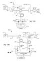
- FIG. 1is a schematic view of an optical coherence tomography (OCT) probe according to a first probe embodiment of the present invention
- FIG. 2is a schematic view of an OCT probe according to a second probe embodiment of the present invention.
- FIG. 3is a schematic view of an OCT probe according to a third probe embodiment of the present invention.
- FIG. 4is a schematic view of an OCT system according to a first system embodiment of the present invention.
- FIG. 5is a schematic view of an OCT system according to a second system embodiment of the present invention.
- FIG. 6is a schematic view of an OCT system according to a third system embodiment of the present invention.
- FIG. 7is a schematic view of an OCT system according to a fourth system embodiment of the present invention.
- FIG. 8Ais a schematic view of an OCT probe that provides for polarization sensitivity according to a first polarization probe embodiment of the present invention
- FIG. 8Billustrates the polarization of input signal, reference signal and return signals
- FIG. 8Cis a schematic view of an OCT probe that provides for polarization sensitivity according to a second polarization probe embodiment of the present invention.
- FIG. 9is a plan view of the optical components of an OCT probe including an integrated reference path
- FIG. 10Ais a schematic view of a polarization sensitive OCT system according to a first polarization system embodiment of the present invention.
- FIG. 10Bis a schematic view of a polarization sensitive OCT system according to a second polarization system embodiment of the present invention.
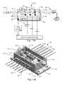
- FIG. 11Ais a schematic plan view of an integrated OCT engine according to the present invention.
- FIG. 11Bis a perspective view of the integrated OCT engine according to the present invention.
- FIG. 12is a schematic plan view of an integrated OCT engine/probe according to the present invention.
- FIG. 1shows an optical coherence tomography (OCT) probe 100 A that has been constructed according to the principles of the present invention (first probe embodiment).
- OCToptical coherence tomography
- the probe 100comprises a handpiece housing 160 .
- This handpiece housingis typically grasped by an operator of the OCT system. It is characterized by a rigid portion that connects to an OCT analysis unit by an intervening flexible or articulated umbilical.
- the housing 160comprises an optical window element 164 , which is typically tilted and anti-reflection coated to prevent spurious reflection back into the OCT system.
- This optical window element 164is transmissive to the optical frequencies at which the OCT system operates. In one example, the OCT system operates in the near infrared. In some embodiments, the optical window 164 is also transmissive to visible optical frequencies to enable a visible targeting beam to pass through the window to indicate where the non-visible infrared OCT signal is impinging on the object of interest 10 .
- the handpiece 160in one implementation includes an electro-optical connector 110 .
- This electro-optical probe connector 110enables operator connection to and disconnection from an OCT analysis system.
- the electro-optical probe connector 110provides the OCT and interference signals between the probe system 100 and the analysis system along with electrical control signals.
- the umbilicalis integral with the probe such that the connector 110 is not used.
- the OCT signalsuch as light from a swept source laser
- the OCT/interference signal fiber 106couples the OCT signal received from the OCT analysis system to an interference/OCT signal coupler 112 .
- the interference/OCT signal coupler 112is a 90/10 percent fiber coupler, and thus does not divide the light evenly between the two output ports.
- the interference/OCT signal coupler 112provides the OCT signal received on the OCT/interference signal fiber 106 to a reference arm optical fiber 130 and a signal arm optical fiber 132 , with most of the light, i.e., 90% or greater, in this current example, on the signal arm optical fiber 132 .
- the reference arm optical fiber 130forms the reference arm of an interferometer that is implemented, preferably entirely, within the handpiece housing 160 .
- the reference arm optical fiber 130terminates in a reflector 116 .
- the reflector 116is simply a highly reflective coating at the end of the reference arm optical fiber 130 .
- Exemplary highly reflective coatingsinclude dielectric stack coatings and metalized endfacet coatings that are deposited on the endfacet of the reference arm optical fiber 130 .
- the reflector 116is implemented as a discrete mirror element, and possibly including a discrete lens to collimate and couple light between the endfacet of the reference arm optical fiber 130 and the mirror reflector.
- the signal arm optical fiber 132transmits the received OCT signal to a scanning unit 150 .
- the scanning unit 150couples the OCT signal between the object of interest 10 and the signal arm optical fiber 132 .
- the scanning unit 150comprises an optional glass or transmissive spacer 152 that is secured to the endfacet of the signal arm optical fiber 132 .
- Thisspaces the endfacet of the signal arm optical fiber 132 from a GRIN (graded refractive index) lens element 154 , which has an angled output facet to prevent parasitic reflections.
- the GRIN lens 154focuses the OCT signal from the signal arm optical fiber 132 onto the sample 10 .
- the free-space light beam 156is directed to a fold mirror 158 that directs the OCT signal beam 156 through the optical window 164 to the object of interest 10 . Then light returning from the object of interest 10 is coupled back through the optical window 164 to reflect off of the fold mirror 158 and be coupled back into the signal arm optical fiber 132 via the GRIN lens 154 and the spacer element 152 .
- the fold mirror 158is a scanning mirror. Specifically, it is driven to both tip and tilt in the x and y axes as indicated by arrow 134 . In one implementation, this is a micro electro mechanical system (MEMS) mirror that scans the OCT signal beam 156 , such as raster scans, over the object of interest 10 in order to generate a three-dimensional image of the object of interest 10 .
- MEMSmicro electro mechanical system
- the handpiece housing 160also supports one or more electrical control switches 162 .
- These control switches 162are coupled to the OCT analysis system via the opto-electrical connector 110 via control line 170 .
- the switchesare used by the operator to begin and end OCT scanning and activate a visible targeting laser during the OCT analysis of the object of interest 10 .
- the switches 162are also used to electronically drive and control the scanning mirror 158 .
- the light returning from the object of interest 10 on the signal arm optical fiber 132is combined with the light returning from the reflector 116 on the reference arm optical fiber 130 in the interference/OCT signal coupler 112 .
- This combinationgenerates the interference signal that is transmitted to the OCT analysis system on the OCT/interference signal optical fiber 106 via the electro-optical connector 110 .
- the length of the reference arm optical fiber 130is important to control the scanning depth in the object. Specifically, the length of the reference arm optical fiber 130 is sized so that plane 175 is the zero distance virtual reference plan of the OCT system. Thus, the optical path length of the reference arm optical fiber 130 is made equal to the sum of the optical path lengths of the signal arm optical fiber 132 , transmissive spacer 152 , GRIN lens element 154 , and the free space path to the reference plane 175 , including window 164 .
- the length of the reference arm optical fiber 130is important to control the scanning depth in the object. Specifically, the length of the reference arm optical fiber 130 is sized so that plane 175 is the zero distance virtual reference plan of the OCT system. Thus, the optical path length of the reference arm optical fiber 132 is made equal to the sum of the optical path lengths of the signal arm optical fiber 132 , transmissive spacer 152 , GRIN lens element 154 , and the free space path to the reference plane 175 , including window 164 .
- the probe 100in some sense a “common path” probe, with one fiber connection back to the OCT system. It would typically be used with some sort of relative intensity noise (RIN) reduction system.
- RINrelative intensity noise
- One optionis to use a balanced receiver to accept input from the probe in one detector and a laser amplitude signal in the other (US2009/0046295 A1, Kemp, et al., Feb. 19, 2009, FIG. 13).
- Another optionis to ratio the probe signal with that of a laser power monitor (Normalization detection scheme for high-speed optical frequency-domain imaging and reflectometry, Sucbei Moon and Dug Young Kim, 12 Nov. 2007/Vol. 15, No. 23/OPTICS EXPRESS 15129).
- FIG. 2shows a second embodiment of the OCT probe 100 B.
- This embodimentis generally similar to the first probe embodiment but uses two OCT/interference signal fibers 106 , 108 to optically connect the OCT probe 100 to the OCT analysis system.
- This probeis compatible with standard balanced receiver/relative intensity noise (RIN) reduction scheme, and would also suppress autocorrelation artifacts from the sample signal interfering with itself.
- RINreceiver/relative intensity noise
- the OCT signal from the OCT analysis systemis received via the electro-optical connector 110 typically through a flexible umbilical on a first OCT/interference signal fiber 106 and a second OCT/interference signal fiber 108 , or only one of these fibers.
- the lightis then coupled to via a 50/50 interference/OCT signal coupler 112 between the reference arm optical fiber 130 and the signal arm optical fiber 132 .
- the OCT signal on the reference arm optical fiberis transmitted to a partial reflector 118 .
- this partial reflectorreflects back less than 10%, such as 4% or less, of the OCT signal light that carried on the reference arm optical fiber 130 .
- this partial reflector 118is implemented as a dielectric stack or metal coating on the endfacet of the optical fiber 130 .
- Light on the signal arm optical fiber 132is transmitted to the scanning unit 150 . This directs the light as described previously through the optical window 164 to the object of interest 10 . Returning light in turn passes through the optical window 164 and is coupled by the scanning unit 150 to the signal arm optical fiber 132 .
- the OCT signal returning on the reference arm optical fiber 130 and the light from the object of interest returning on the signal arm optical fiber 132is combined in the 50/50 interference/OCT signal coupler 112 . This combination generates the interference signal that is transmitted back to the OCT analysis system on the first and second OCT/interference signal fibers 106 , 108 via the electro-optical connector 110 .
- FIG. 3shows a third embodiment of the OCT probe system 100 C.
- This embodimentis similar to the second embodiment OCT probe system of FIG. 2 .
- the differencelies in the configuration of the reference arm.
- the reference arm optical fiber 130includes an attenuator 120 that attenuates the OCT signal carried on the reference arm optical fiber 130 .
- the light passing through the attenuator 120is then reflected by a highly reflecting endfacet 116 .
- This highly reflecting end facetis typically implemented as described in connection with the first probe embodiment of FIG. 1 .
- the OCT light returning from the reflector 116passes through the attenuator 120 and then on the reference arm optical fiber 130 to the interference/OCT signal coupler 112 .
- the potential problem associated with the embodiment of FIG. 2is dissipating the light that is transmitted through the partial reflector 118 .
- This transmitted lightis then potentially within the handpiece housing 116 and can potentially serve as an interference source: either being coupled back into the reference arm optical fiber 130 creating multipath interference or possibly interfering with the OCT signal that is transmitted to and from the object of interest 10 .
- This potential problemis addressed in the embodiment of FIG. 3 by using the attenuator 120 to absorb the excess OCT signal light in the reference arm to ensure that it does not create interference.
- the attenuator 120is a lossy element that is implemented by fiber microbending, through a lossy fiber splice, or other means.
- FIG. 4illustrates an OCT analysis system 200 A that is compatible with the OCT probe of FIG. 1 .
- the OCT analysis system 200 Aprovides electrical and optical connection to the probe 100 via a typically flexible or articulated umbilical 205 .
- this umbilicalextends between an OCT analysis system electro-optical connector 218 and the probe connector 110 .
- This flexible umbilical 205allows the reference probe 100 to be moved around the object of interest, such as the patient, to enable analysis of regions of interest of the patient, such as the patient's teeth or skin in some examples.
- the OCT signal receive by the probe 100is generated in the preferred embodiment by a swept laser source 212 .
- An exemplary sourceis that described in U.S. patent application Ser. No. 12/396,099, filed on 2 Mar. 2009, entitled Optical Coherence Tomography Laser with Integrated Clock, by Flanders, et al., which is incorporated herein by this reference.
- the OCT signal generated by the swept source laseris transmitted to a 50/50 OCT/amplitude reference fiber coupler 214 on a swept source optical fiber 235 .
- the 50/50 coupler 214divides the OCT signal from the swept source 212 between an amplitude reference fiber 216 and the OCT probe optical fiber 240 .
- This OCT probe optical fiber 240transmits the OCT signal from the 50/50 coupler 214 to the unit connector 218 .
- the returning interference signal from the reference probe 100is received via the unit connector 218 on the probe optical fiber 240 and is then divided by the 50/50 OCT/amplitude reference fiber coupler 214 .
- the path match optical fiber 216has a length that corresponds to twice the optical delay between the OCT/amplitude reference fiber coupler 214 and the reference probe 110 plus the delay from coupler 214 to interference signal photodiode detector 230 . In this way, the delay induced by the path match optical fiber is consistent with the combined delay associated with OCT signal to the probe 100 and the interference signal returning on optical fiber 240 from the probe.
- the OCT signal light transmitted through the path match optical fiber 216is then detected by an amplitude reference photodiode detector 220 which is then sampled by the controller 210 and used to remove amplitude noise in the system from the swept source 212 .
- the interference signal returning from the OCT probe 100 and received on OCT probe optical fiber 240is transmitted through the 50/50 OCT/amplitude reference fiber coupler 214 to the interference signal detector 230 .
- This detectordetects that light which is then sampled by the controller 210 .
- the amplitude reference detector 220 and the interference detector 230are combined into a balanced detector system for rejection of the amplitude noise from the swept source 212 in the interference signal.
- the optical power levels at the two detectorsneed to be balanced (For example, see a similar RIN reduction scheme in US2009/0046295 A1, Kemp, et al., Feb. 19, 2009, FIG. 13).
- the signal from the amplitude reference detector 220can be digitally divided in the controller 212 , for example, by the interference signal from detector 230 for RIN reduction (Normalization detection scheme for high-speed optical frequency-domain imaging and reflectometry, Sucbei Moon and Dug Young Kim, 12 Nov. 2007/Vol. 15, No. 23/OPTICS EXPRESS 15129).
- FIG. 5illustrates a second system embodiment 200 B of the OCT analysis system that is also compatible with the probe of FIG. 1 .
- This systemmakes more efficient use of the available optical power, but has more expensive components.
- the second embodiment 200 Buses an unbalanced OCT/amplitude reference fiber coupler 214 to divide the OCT signal from the swept source 212 between the amplitude reference path match fiber 216 and OCT probe optical fiber 240 .
- the OCT signal light on the OCT probe optical fiber 240passes through interference signal circulator 242 to be transmitted to the reference probe 100 via the unit electro-optical connector 218 .
- the interference signal returning from the reference probe 100is directed by the circulator 242 to interference signal detector 230 .
- the circulator 242leads to a more optically efficient system relative to FIG. 4 since the 95/5% OCT/amplitude reference fiber coupler 214 of this embodiment allows most of the OCT signal, greater than 90% and preferably 95% or more, generated by the swept source 212 to be directed to the object of interest with only a small amount being used to generate the amplitude reference.
- FIG. 6illustrates a third embodiment 200 C of the OCT analysis system that is compatible with the probes of FIGS. 2 and 3 .
- the OCT signal generated by the swept source 212is transmitted on swept source optical fiber 235 to interference signal circulator 242 and then on OCT probe optical fiber 240 to the optical probe 100 via the unit connector 218 .
- the interference signal from the OCT probeis then received on interference signal optical fiber 244 and the OCT probe optical fiber 240 .
- the returning interference signal light on OCT probe optical fiber 240is directed by the interference signal circulator 242 to the balanced detector 248 .
- the interference signal received on the interference signal optical fiber 244is directly coupled to the balanced detector 248
- the balanced receiverreduces the effect of RIN on the system's signal-to-noise ratio.
- the common-path probe systems in FIGS. 4 and 5also have methods to reduce the effects of RIN.
- a major advantage of the two-fiber probe ( FIGS. 2 and 3 ) and the corresponding system ( FIG. 6 )is that the autocorrelation image (sample light interfering with itself) is strongly attenuated.
- the balanced receiver 248is an auto-balanced receiver (one example is manufactured by New Focus. Part number 2017), which automatically balances the electrical signals from the two detectors even in the presence of mismatched lightwave signals impinging on the two detectors.
- FIG. 7illustrates a variant, fourth embodiment 200 B of the OCT system that uses two circulators 252 , 254 for the two fiber probe embodiments.
- This configurationis similar to that in FIG. 6 , except that it incorporates a “dummy” circulator 254 (one port not used) to help balance the lightwave signals present at the two detectors of the balanced receiver 248 .
- the interference signal circulators 252 , 254will have similar optical losses vs. wavelength and balance the lightwave signals to the two detectors.
- a better matchprovides improves signal-to-noise performance and attenuation of the autocorrelation image.
- Better matching by the additional circulationmay be preferred to the use of an autobalanced detector for cost and performance reasons.
- FIG. 8Aillustrates a first polarization sensitive embodiment 100 D of the OCT probe 100 .
- this OCT probeis similar to the first probe embodiment of FIG. 1 , thus, the descriptions associated with FIG. 1 are relevant here.
- This probe 100 Dallows for polarization dependent or sensitive OCT analysis. Specifically, it enables the analysis of the OCT signal and the polarization characteristics of the object of interest 10 .
- the OCT signal received on the OCT/Interference signal fiber 106is a highly polarized signal such as a signal from a semiconductor external cavity laser system.
- the OCT/Interference signal fiber 106is polarization maintaining optical fiber.
- the polarization of the swept source OCT signalis polarized according to one, slow, axis of the polarization maintaining (PM) fiber 106 that is used for the OCT/Interference signal fiber 106 . See polarization 190 .
- the polarized OCT signalis divided by the interference/OCT signal coupler 112 , which is a 50/50 polarization-maintaining coupler.
- the polarized OCT lightis transmitted over the reference arm optical fiber 130 , which is PM fiber, to the reflector 116 .
- the returning OCT signal lighthas both a portion that is polarized parallel to the input OCT signal but also perpendicular to the input OCT signal, see polarization 192 in FIG. 8B .
- FIG. 8Cshows a second embodiment polarization sensitive probe 100 E that is analogous to the two fiber probes of FIGS. 2 and 3 and is compatible with standard balanced receiver/relative intensity noise (RIN) reduction scheme, and would also suppress autocorrelation artifacts from the sample signal interfering with itself.
- RINreceiver/relative intensity noise
- the lightis then coupled to via a 50/50 interference/OCT signal PM fiber coupler 112 between the reference arm optical fiber 130 and the signal arm optical fiber 132 , which are both constructed of PM fiber.
- the OCT signal on the reference arm optical fiber 130is transmitted to a partial reflector 118 .
- this partial reflectorreflects back less than 10%, such as 4% or less, of the OCT signal light that carried on the reference arm optical fiber 130 .
- attenuator 120is used in combination with a highly reflecting reflector. In either case, the intervening quarterwave plate 810 shifts the polarization so that the returning OCT signal now has component polarizations along each axis of the PM fiber.
- Light on the signal arm PM optical fiber 132is transmitted to the scanning unit 150 . This directs the light as described previously through the optical window 164 to the object of interest 10 . Returning light in turn passes through the optical window 164 and is coupled by the scanning unit 150 to the signal arm PM optical fiber 132 .
- the OCT signal returning on the reference arm optical fiber 130 and the light from the object of interest returning on the signal arm optical fiber 132is combined in the 50/50 interference/OCT PM fiber coupler 112 .
- This combinationgenerates the interference signal for each polarization that is transmitted back to the OCT analysis system on the first and second OCT/interference PM fibers 106 , 108 via the electro-optical connector 110 .
- FIG. 9illustrates an OCT probe 100 F that includes an integrated reference arm.
- the OCT signal from the swept source laseris transmitted on an OCT/Interference signal optical fiber 410 .
- the OCT signalis coupled to the probe body 422 .
- an intervening graded index fiber 420connects the OCT/Interference signal optical fiber 410 to the probe body 422 .
- the graded index fiber 420collimates the OCT signal so that the beam 440 that is transmitted through the optical probe body 422 is collimated.
- the lightpasses through interface 424 to be directed to a scanning fold mirror 158 , which scans see arrow 134 . This allows the OCT signal beam 156 to be scanned over the object of interest 10 .
- Light returning from the object of interestis directed by the scanning fold mirror 158 through interface 424 to be directed back into the OCT/interference signal fiber 410 via the graded index fiber 420 .
- the probe body 422includes an integrated reference arm.
- the interface 424is a partial reflector so that a portion, typically less than 10%, of the OCT signal beam 440 is directed to a reference arm that is within the transmissive probe body 422 to be directed to an interface 428 that has a high reflecting coating on it. This reflects light back to the interface 422 to mix or combine with the light returning from the object of interest to generate the interference signal that is then coupled via the graded index fiber 420 to the OCT/Interference signal fiber 410 .
- this integrated OCT probeperforms polarization dependent OCT analysis.
- a quarterwave plate 430is attached to the probe body 422 to the interface 428 to rotate the light so that the light is now polarized along both axes.
- the OCT/interference signal fiber 410is then polarization maintaining fiber.
- FIG. 10Ashows a first embodiment of a swept source polarization sensitive OCT system 200 E that is compatible with the polarization sensitive, common path probes of FIGS. 8A and 9 .
- all of the optical fibers in the systemare polarization maintaining.
- the swept source laser 212provides a linearly polarized output aligned to the slow axis of the PM fiber of the system and specifically the PM fiber used for the swept source optical fiber 235 .
- the OCT/amplitude reference fiber coupler 214is similarly a PM fiber coupler that divides light between the amplitude path match fiber 216 and the OCT probe PM fiber 240 .
- the OCT/amplitude reference fiber coupler 214is an unbalanced coupler so that most of the OCT signal is transmitted to the sample, i.e., greater than 90% and preferably 95% or more.
- the OCT signal light on the OCT probe optical fiber 240passes through interference signal circulator 242 to be transmitted to the reference probe 100 via the OCT probe optical fiber 240 and potentially a unit optical connector 218 , umbilical 205 , and probe connector 110 .
- the interference signal returning from the reference probe 100is directed by the circulator 242 through a length of detector PM optical fiber 910 .
- This fiberhas a long length so that mixing of the parallel polarized light and the perpendicular light occurs at a frequency that is cut by an anti-aliasing filter 912 between the optical detectors 918 , 920 and the analog-to-digital converters of the controller 210 that are used to sample the detector signals.
- the anti-alias filterremoves any OCT image information at displacements greater than 5 mm
- the fibermust be long enough that returns for the slow and fast axis light are separated >5 mm over the propagation distance.
- a typical fiber lengthis tens of meters for a few m of displacement.
- An interference signal polarization splitter 914which can be implemented with fiber-optic components or bulk optic components, separates the two signals of different polarizations and routes them to separate detectors, a parallel polarization detector 918 and a perpendicular polarization detector 920 .
- the system controller 210generates and displays two images by separately processing the interference signals of the two polarizations: One where the light scattered from the sample 10 has the same polarization as the illumination light generated by the swept source laser 212 , the parallel light; and a second image where the scattered light is polarized perpendicular to the illumination light.
- FIG. 10Bshows a polarization sensitive OCT analysis system 200 F that is compatible with the polarization dependent, two-fiber probe of FIG. 8C .
- the OCT signal generated by the swept source 212is transmitted on swept source optical fiber 235 to interference signal circulator 252 and then on OCT probe optical fiber 240 to the optical probe 100 , via potentially a unit optical connector 218 , umbilical 205 , and probe connector 110 .
- the interference signal from the OCT probeis then received on interference signal optical fiber 244 and the OCT probe optical fiber 240 .
- Returning interference signal light on OCT probe optical fiber 240is directed by the circulator 252 to the detectors.
- the interference signal received on the interference signal optical fiber 244directed to the detectors by circulator 254 .
- long lengths of PM fiber 910 a , 910 bare used on the optical paths to the detectors to prevent cross mixing of the parallel and perpendicular waves.
- the PM detector fibers 910 a , 910 bshould have matched lengths.
- a first interference signal polarization splitter 914 aseparates the polarizations of the interference signal received from interference signal circulator 252 .
- a second interference signal polarization splitter 914 bseparates the polarizations of the interference signal received from interference signal circulator 254 .
- perpendicular polarization interference signals from each splitter 914 a , 914 bare detected by a perpendicular balanced detector 248 b and the parallel polarization interference signals are detected by parallel polarization balanced detector 248 a.
- This systemhas the RIN reduction and autocorrelation image suppression properties of the polarization insensitive systems of FIGS. 2 and 3 , because of the use of balanced detection.
- the PM fibers 910 a and 910 bwould have to be long to prevent polarization mixing as described above. They need to be roughly matched in length, so that the propagation delay difference is much less than the reciprocal of the highest electrical frequency generated in the detector systems.
- FIG. 11Ashows an integrated polarization dependent OCT system 500 that has been constructed according to the principals of the present invention and is compatible with the OCT probes of FIGS. 8A and 9 .
- the integrated polarization dependent OCT system 500comprises a tunable swept source laser subsystem 510 , which generates a wavelength or frequency tunable optical signal, a clock subsystem 520 , which generates k-clock signals at spaced frequency increments as the OCT signals or emissions of the laser 510 are spectrally tuned over a spectral scan band, and a detector subsystem 530 , which includes an amplitude references and interference signal detectors.
- the k-clock signalsare used to trigger sampling, typically in an OCT sampling analog to digital converter (A/D) system 505 .
- A/DOCT sampling analog to digital converter
- the detector subsystem 530 and clock subsystem 520 of the integrated polarization dependent OCT system 500are integrated together on a common optical bench 550 .
- This benchis termed a micro-optical bench and is typically less than 20 millimeters (mm) by 30 mm in size, and preferably less than 10 millimeters (mm) by 20 mm in size so that it fits within a standard butterfly or DIP (dual inline pin) hermetic package 560 .
- the benchis fabricated from aluminum nitride.
- a thermoelectric cooler 561is preferably disposed between the bench 550 and the package 560 (attached/solder bonded both to the backside of the bench 550 and inner bottom panel of the package 560 ) to control the temperature of the bench 550 .
- an input lens structure 514is used.
- the input lens structure 514comprises a LIGA mounting structure, which is deformable to enable post installation alignment, and a transmissive substrate in which the lens is formed.
- the transmissive substrateis typically solder or thermocompression bonded to the mounting structure, which in turn is solder bonded to the optical bench 550 .
- the input lens structure 514couples the light from the laser 510 to a partially reflecting 10/90 substrate that functions as input beam splitter 516 .
- a majority of the beamenters the detector subsystem 530 and the remaining beam is directed to the clock subsystem 520 .
- greater than 90% of the input beam from the laser 510is directed to the detector subsystem 530 .
- the OCT signal lightis divided in the clock subsystem by a clock beam splitter 522 , which is preferably a 50/50 splitter.
- the clock beam splitter 522divides the light between to a clock etalon 524 and a k-clock detector 526 . Any light not reflected by the splitter 522 is directed to a beam dump component that absorbs the light and prevents parasitic reflections in the hermetic package 560 .
- the clock etalon 524functions as a spectral filter. Its spectral features are periodic in frequency and spaced spectrally by a frequency increment, termed free spectral range (FSR), that is related to the refractive index of the constituent material of the clock etalon 524 , which is fused silica in one example, and the physical length of the clock etalon 524 .
- FSRfree spectral range
- the etaloncan alternatively be made of other high-index and transmissive materials such as silicon for compactness, but the optical dispersion of the material may need to be compensated for with additional processing inside the controller/DSP 505 .
- air-gap etalonswhich are nearly dispersionless, are another alternative.
- the contrast of the spectral features of the etalonis determined by the reflectivity of its opposed endfaces.
- reflectivity at the etalon endfacesis provided by the index of refraction discontinuity between the constituent material of the etalon and the surrounding gas or vacuum.
- the opposed endfacesare coated with metal or preferably dielectric stack mirrors to provide higher reflectivity and thus contrast to the periodic spectral features.
- the clock etalon 524is operated in reflection.
- the FSR of the clock etalonis chosen based on the required scanning depth in an OCT system.
- the Nyquist criteriondictates that the periodic frequency spacing of the clock etalon that defines the sample rate be twice the largest frequency period component of the sample, thus setting the optical thickness of the clock etalon to twice the required imaging depth.
- the periodic waveformcan be electrically frequency doubled, tripled, etc, see doubler 528 , or can be halved to obtain the desired sample rate while choosing an etalon of a length that is convenient for handling and that easily fits within the package 560 and on the bench 550 .
- a thicker etaloncompensates better for nonlinear frequency scanning than a thinner one due to its finer sample rate, but it is larger and more difficult to fabricate, so a tradeoff is made depending upon the laser tuning linearity, system depth requirements, and manufacturing tolerances.
- a thicker etalonrequires a laser of comparable coherence length to generate stable clock pulses, so the laser coherence length can also help dictate the design of the etalon thickness.
- the light returning from the clock etalon 524 and not reflected by beamsplitter 522is detected by detector 526 .
- the light detected by detector 526is characterized by drops and rises in power as the frequency of the tunable signal scans through the reflective troughs/reflective peaks provided by the clock etalon 524 .
- the detector photocurrentis amplified and conditioned.
- the clock signalis multiplied or divided in frequency by multiplier/divider 528 , depending on the needs of the OCT system's application and the requirement for a convenient etalon (or other clock interferometer) size within the butterfly package 560 .
- a digital delay lineis also added to the doubler circuitry 528 is some embodiments to compensate for any round-trip optical delay to the probe 400 .
- the OCT signal that is transmitted through the input beam splitter 516enters the detector subsystem 530 .
- the detector subsystem 530comprises an amplitude reference splitter 562 that directs a portion of the OCT signal, typically less than 10%, to an amplitude reference detector 564 . This detector 564 is used to detect amplitude noise in the OCT signal.
- Light transmitted through the amplitude reference splitter 562passes through a parallel detector splitter 566 , a polarization beam splitter 568 and is coupled onto OCT/Interference signal optical fiber 410 to the polarization dependent OCT probe 400 by output lens structure 518 .
- the returning interference signal from the OCT probe 400is separated into its two polarizations by the polarization beam splitter 568 .
- the portion of the interference signal that is perpendicular to the polarization of the OCT signal from the laser 510is directed to and detected by a perpendicular interference signal detector 570 .
- the portion of the interference signal that has a polarization that is parallel to the polarization of the polarization of the OCT signal from the laser 510 and that passed through the polarization beam splitter 568is directed by the parallel detector splitter 566 and detected by the parallel interference signal detector 572 .
- the k-clock signalis used by the digital signal processing and analog-detector sampling system 505 as a sampling clock to trigger the sampling of the amplitude reference signal, the parallel detector signal, and the perpendicular detector signal. This information is used to perform the Fourier transform to reconstruct the image of the object including a polarization dependent OCT image at the two polarizations.
- FIG. 11Bshows one physical implementation of the integrated polarization dependent OCT system 500 in a butterfly package 560 .
- the lid of the package 560is removed to expose the components of the bench 560 .
- This viewalso shows the LIGA structures S that attach the lens substrates L to the bench 560 .
- FIG. 12shows another integrated OCT system 600 that has been constructed according to the principals of the present invention.
- This systemintegrates the swept source 610 , k-clock system 520 , detector system 530 , and reference arm 660 on a bench 550 , and within a hermetic package 560 .
- the integrated laser clock system 600comprises a tunable laser swept source subsystem 610 , which generates a wavelength or frequency tunable OCT signal, a clock subsystem 520 , which generates k-clock signals at spaced frequency increments as the tunable signals or emissions of the laser 610 are spectrally tuned over a spectral scan band, and a detector subsystem 530 .
- the clock signalsare generally used to trigger sampling of detector system.
- the tunable laser subsystem 610 , clock subsystem 520 , and the detector subsystem 530are integrated together on a common optical bench 550 .
- This benchis termed a micro-optical bench and is usually less than 20 mm by 30 mm and preferably less than 10 mm by 20 mm in size so that it fits within a standard butterfly or DIP (dual inline pin) hermetic package 560 .
- the benchis fabricated from aluminum nitride.
- a thermoelectric cooler 562is disposed between the bench 550 and the package 560 (attached/solder bonded both to the backside of the bench and inner bottom panel of the package 560 ) to control the temperature of the bench 550 .
- the tunable laser 610 in the preferred embodimentin based on the tunable laser designs disclosed in U.S. Pat. No. 7,415,049 B2, which is incorporated herein in its entirety by this reference.
- the tunable laser 610comprises a semiconductor gain chip 652 that is paired with a micro-electro-mechanical (MEMS) angled reflective Fabry-Perot tunable filter 654 to create external cavity laser (ECL) with the tunable filter 654 being an intracavity tuning element and forming one end, or back reflector, of a laser cavity of the tunable ECL.
- MEMSmicro-electro-mechanical
- ECLexternal cavity laser
- the semiconductor optical amplifier (SOA) chip 652is located within the laser cavity.
- both facets of the SOA chip 652are angled relative to a ridge waveguide 58 running longitudinally along the chip 652 with the back facet 651 and the front facet 655 being anti-reflection (AR) coated.
- a partially reflecting substrate 662provides reflectivity to define the front reflector of the laser cavity.
- Each lens structure 660 , 662comprises a LIGA mounting structure, which is deformable to enable post installation alignment, and a transmissive substrate in which the lens is formed.
- the transmissive substrateis typically solder or thermocompression bonded to the mounting structure, which in turn is solder bonded to the optical bench 550 .
- the first lens component 660couples the light between the back facet of the SOA 652 and the tunable filter 654 .
- Light exiting out the front facet of the SOA 652is coupled by a second lens component 662 to the detector subsystem 530 .
- the angled reflective Fabry-Perot filter 654is a multi-spatial-mode tunable filter having a curved-flat optical resonant cavity that provides angular-dependent, reflective spectral response back into the laser cavity. This effect is discussed in more detail in incorporated U.S. Pat. No. 7,415,049 B2.
- the curved mirroris on the MEMS membrane and is on the side of the filter 654 that adjoins the laser cavity.
- the flat mirroris on the opposite side and faces the laser cavity.
- the flat mirrorpreferably has a higher reflectivity than the curved mirror.
- the reflectivities for the flat and curved mirrorsare typically 99.98% and 99.91%, respectively, in order to achieve the desired reflectivity and requisite linewidth of the filter 654 in reflection.
- the light transmitted by the tunable filter 654is coupled out of the laser cavity and into the clock subsystem 520 by fold mirror 614 , which are reflective coated substrates that are solder bonded to the bench 550 , fold the beam of the light from the tunable laser subsystem 610 , allowing for a dimensionally compact system.
- the lightthen passes to a beam splitter 522 , which is preferably a 50/50 splitter to a clock etalon 524 .
- a beam splitter 522is preferably a 50/50 splitter to a clock etalon 524 .
- Any light transmitted by the splitter 522is preferably directed to a beam dump component that absorbs the light and prevents parasitic reflections in the hermetic package 560 and into the laser cavity and detectors.
- the light returning from the clock etalon 524is detected by detector 526 to form the k-clock signal.
- the detector subsystem 530receives the OCT signal from the tunable laser subsystem 610 .
- the OCT signalpasses through an amplitude reference splitter 562 , and interference/reference splitter 620 .
- the OCT signalis focused by an output lens 622 on the object of interest 10 .
- the OCT signalexits the hermetic package 560 via a transmissive window 630 that is provided in the side of the package 560 .
- the OCT signal that is reflected by the interference/reference splitter 620is directed to a reference arm 660 including reference arm fold mirror 624 to a reference arm mirror 626 .
- Light returning from the reference arm mirror 624is mixed or combined with light from the sample 10 , which is received by received by window 630 and focused by lens 622 , at interference/reference splitter 620 to form the interference signal that is detected by interference signal detector 628 .
- SNR improvementby reducing the effects of RIN is performed by digitally dividing the interference signal from detector 628 by the amplitude reference signal from detector 564 before FFT processing. This is a compact system for performing A-scans, but movement of the package 560 or the sample 10 would allow B-scans to be made. Additionally, a MEMS mirror scanner could be incorporated before the package's output lens to perform this function without movement of the sample or the package in some implementation.
Landscapes
- Health & Medical Sciences (AREA)
- Physics & Mathematics (AREA)
- Life Sciences & Earth Sciences (AREA)
- General Physics & Mathematics (AREA)
- General Health & Medical Sciences (AREA)
- Nuclear Medicine, Radiotherapy & Molecular Imaging (AREA)
- Radiology & Medical Imaging (AREA)
- Pathology (AREA)
- Molecular Biology (AREA)
- Veterinary Medicine (AREA)
- Heart & Thoracic Surgery (AREA)
- Medical Informatics (AREA)
- Engineering & Computer Science (AREA)
- Surgery (AREA)
- Animal Behavior & Ethology (AREA)
- Biophysics (AREA)
- Public Health (AREA)
- Biomedical Technology (AREA)
- Optics & Photonics (AREA)
- Chemical & Material Sciences (AREA)
- Analytical Chemistry (AREA)
- Biochemistry (AREA)
- Immunology (AREA)
- Investigating Or Analysing Materials By Optical Means (AREA)
- Instruments For Measurement Of Length By Optical Means (AREA)
- Length Measuring Devices By Optical Means (AREA)
Abstract
Description
Claims (5)
Priority Applications (4)
| Application Number | Priority Date | Filing Date | Title |
|---|---|---|---|
| US12/466,993US8259303B2 (en) | 2008-05-15 | 2009-05-15 | OCT combining probes and integrated systems |
| US13/568,717US9772177B2 (en) | 2008-05-15 | 2012-08-07 | Integrated optical coherence analysis system |
| US13/568,507US20120300215A1 (en) | 2008-05-15 | 2012-08-07 | OCT Combining Probes and Integrated Systems |
| US15/714,365US11092426B2 (en) | 2008-05-15 | 2017-09-25 | Integrated optical coherence analysis system |
Applications Claiming Priority (2)
| Application Number | Priority Date | Filing Date | Title |
|---|---|---|---|
| US5324108P | 2008-05-15 | 2008-05-15 | |
| US12/466,993US8259303B2 (en) | 2008-05-15 | 2009-05-15 | OCT combining probes and integrated systems |
Related Child Applications (2)
| Application Number | Title | Priority Date | Filing Date |
|---|---|---|---|
| US13/568,717DivisionUS9772177B2 (en) | 2008-05-15 | 2012-08-07 | Integrated optical coherence analysis system |
| US13/568,507ContinuationUS20120300215A1 (en) | 2008-05-15 | 2012-08-07 | OCT Combining Probes and Integrated Systems |
Publications (2)
| Publication Number | Publication Date |
|---|---|
| US20090284749A1 US20090284749A1 (en) | 2009-11-19 |
| US8259303B2true US8259303B2 (en) | 2012-09-04 |
Family
ID=40886242
Family Applications (4)
| Application Number | Title | Priority Date | Filing Date |
|---|---|---|---|
| US12/466,993Active2029-08-24US8259303B2 (en) | 2008-05-15 | 2009-05-15 | OCT combining probes and integrated systems |
| US13/568,717ActiveUS9772177B2 (en) | 2008-05-15 | 2012-08-07 | Integrated optical coherence analysis system |
| US13/568,507AbandonedUS20120300215A1 (en) | 2008-05-15 | 2012-08-07 | OCT Combining Probes and Integrated Systems |
| US15/714,365Active2030-03-11US11092426B2 (en) | 2008-05-15 | 2017-09-25 | Integrated optical coherence analysis system |
Family Applications After (3)
| Application Number | Title | Priority Date | Filing Date |
|---|---|---|---|
| US13/568,717ActiveUS9772177B2 (en) | 2008-05-15 | 2012-08-07 | Integrated optical coherence analysis system |
| US13/568,507AbandonedUS20120300215A1 (en) | 2008-05-15 | 2012-08-07 | OCT Combining Probes and Integrated Systems |
| US15/714,365Active2030-03-11US11092426B2 (en) | 2008-05-15 | 2017-09-25 | Integrated optical coherence analysis system |
Country Status (4)
| Country | Link |
|---|---|
| US (4) | US8259303B2 (en) |
| EP (2) | EP2677272B1 (en) |
| JP (1) | JP5538368B2 (en) |
| WO (1) | WO2009140617A2 (en) |
Cited By (17)
| Publication number | Priority date | Publication date | Assignee | Title |
|---|---|---|---|---|
| US20120300215A1 (en)* | 2008-05-15 | 2012-11-29 | Axsun Technologies, Inc. | OCT Combining Probes and Integrated Systems |
| US8655431B2 (en) | 2011-05-31 | 2014-02-18 | Vanderbilt University | Apparatus and method for real-time imaging and monitoring of an electrosurgical procedure |
| US20140176937A1 (en)* | 2011-08-18 | 2014-06-26 | Tiegen Liu | Distributed disturbance sensing device and the related demodulation method based on polarization sensitive optical frequency domain reflectometry |
| US9351698B2 (en) | 2013-03-12 | 2016-05-31 | Lightlab Imaging, Inc. | Vascular data processing and image registration systems, methods, and apparatuses |
| US9757038B2 (en) | 2011-05-31 | 2017-09-12 | Vanderbilt University | Optical coherence tomography probe |
| US9996921B2 (en) | 2015-05-17 | 2018-06-12 | LIGHTLAB IMAGING, lNC. | Detection of metal stent struts |
| US10109058B2 (en) | 2015-05-17 | 2018-10-23 | Lightlab Imaging, Inc. | Intravascular imaging system interfaces and stent detection methods |
| US10105107B2 (en) | 2015-01-08 | 2018-10-23 | St. Jude Medical International Holding S.À R.L. | Medical system having combined and synergized data output from multiple independent inputs |
| US10172582B2 (en) | 2015-11-18 | 2019-01-08 | Lightlab Imaging, Inc. | X-ray image feature detection and registration systems and methods |
| US10222956B2 (en) | 2015-05-17 | 2019-03-05 | Lightlab Imaging, Inc. | Intravascular imaging user interface systems and methods |
| US10453190B2 (en) | 2015-11-23 | 2019-10-22 | Lightlab Imaging, Inc. | Detection of and validation of shadows in intravascular images |
| US10499813B2 (en) | 2014-09-12 | 2019-12-10 | Lightlab Imaging, Inc. | Methods, systems and apparatus for temporal calibration of an intravascular imaging system |
| US10593037B2 (en) | 2016-04-14 | 2020-03-17 | Lightlab Imaging, Inc. | Method, apparatus, and system to identify branches of a blood vessel |
| US10631754B2 (en) | 2016-05-16 | 2020-04-28 | Lightlab Imaging, Inc. | Intravascular absorbable stent detection and diagnostic methods and systems |
| US10646198B2 (en) | 2015-05-17 | 2020-05-12 | Lightlab Imaging, Inc. | Intravascular imaging and guide catheter detection methods and systems |
| US11287961B2 (en) | 2015-07-25 | 2022-03-29 | Lightlab Imaging, Inc. | Intravascular data visualization and interface systems and methods |
| US11727534B2 (en) | 2020-12-08 | 2023-08-15 | International Business Machines Corporation | Normalizing OCT image data |
Families Citing this family (136)
| Publication number | Priority date | Publication date | Assignee | Title |
|---|---|---|---|---|
| US9867530B2 (en) | 2006-08-14 | 2018-01-16 | Volcano Corporation | Telescopic side port catheter device with imaging system and method for accessing side branch occlusions |
| EP2178442B1 (en) | 2007-07-12 | 2017-09-06 | Volcano Corporation | Catheter for in vivo imaging |
| WO2009009801A1 (en) | 2007-07-12 | 2009-01-15 | Volcano Corporation | Apparatus and methods for uniform frequency sample clocking |
| WO2009009802A1 (en) | 2007-07-12 | 2009-01-15 | Volcano Corporation | Oct-ivus catheter for concurrent luminal imaging |
| US9596993B2 (en) | 2007-07-12 | 2017-03-21 | Volcano Corporation | Automatic calibration systems and methods of use |
| US8395781B2 (en) | 2007-07-12 | 2013-03-12 | Volcano Corporation | Automatic calibration systems and methods of use |
| US9788790B2 (en) | 2009-05-28 | 2017-10-17 | Avinger, Inc. | Optical coherence tomography for biological imaging |
| US8696695B2 (en) | 2009-04-28 | 2014-04-15 | Avinger, Inc. | Guidewire positioning catheter |
| US9125562B2 (en) | 2009-07-01 | 2015-09-08 | Avinger, Inc. | Catheter-based off-axis optical coherence tomography imaging system |
| JP5306075B2 (en)* | 2008-07-07 | 2013-10-02 | キヤノン株式会社 | Imaging apparatus and imaging method using optical coherence tomography |
| DE102009021580B3 (en) | 2009-05-15 | 2010-11-25 | Medizinisches Laserzentrum Lübeck GmbH | Forward scanning OCT endoscope |
| WO2011003006A2 (en) | 2009-07-01 | 2011-01-06 | Avinger, Inc. | Atherectomy catheter with laterally-displaceable tip |
| WO2011072068A2 (en) | 2009-12-08 | 2011-06-16 | Avinger, Inc. | Devices and methods for predicting and preventing restenosis |
| GB2478590A (en)* | 2010-03-12 | 2011-09-14 | Precitec Optronik Gmbh | Apparatus and method for monitoring a thickness of a silicon wafer |
| ES2645392T3 (en)* | 2010-03-17 | 2017-12-05 | Lightlab Imaging, Inc. | Methods and apparatus for intensity noise reduction for interferometric detection and imaging systems |
| WO2011115627A1 (en)* | 2010-03-19 | 2011-09-22 | Duke University | Single-mode optical fiber-based angle-resolved low coherence interferometric (lci) (a/lci) and non-interferometric systems and methods |
| US10548478B2 (en) | 2010-07-01 | 2020-02-04 | Avinger, Inc. | Balloon atherectomy catheters with imaging |
| US11382653B2 (en) | 2010-07-01 | 2022-07-12 | Avinger, Inc. | Atherectomy catheter |
| US9345510B2 (en) | 2010-07-01 | 2016-05-24 | Avinger, Inc. | Atherectomy catheters with longitudinally displaceable drive shafts |
| WO2014039096A1 (en) | 2012-09-06 | 2014-03-13 | Avinger, Inc. | Re-entry stylet for catheter |
| US11141063B2 (en) | 2010-12-23 | 2021-10-12 | Philips Image Guided Therapy Corporation | Integrated system architectures and methods of use |
| US8687666B2 (en)* | 2010-12-28 | 2014-04-01 | Axsun Technologies, Inc. | Integrated dual swept source for OCT medical imaging |
| US8437007B2 (en)* | 2010-12-30 | 2013-05-07 | Axsun Technologies, Inc. | Integrated optical coherence tomography system |
| US9046337B2 (en)* | 2010-12-30 | 2015-06-02 | Volcano Corporation | Integrated OCT detector system with transimpedance amplifier |
| US11040140B2 (en) | 2010-12-31 | 2021-06-22 | Philips Image Guided Therapy Corporation | Deep vein thrombosis therapeutic methods |
| US20130023912A1 (en) | 2010-12-31 | 2013-01-24 | Volcano Corporation | Multiple Sclerosis Therapeutic Methods Using Therapeutic Cutting Devices and Systems |
| US9204800B2 (en)* | 2011-03-07 | 2015-12-08 | St. Jude Medical, Inc. | Low cost high efficiency signal interrogation for multi-channel optical coherence tomography |
| US9949754B2 (en) | 2011-03-28 | 2018-04-24 | Avinger, Inc. | Occlusion-crossing devices |
| EP2691038B1 (en) | 2011-03-28 | 2016-07-20 | Avinger, Inc. | Occlusion-crossing devices, imaging, and atherectomy devices |
| CN103959043B (en) | 2011-05-31 | 2016-11-02 | 光学实验室成像公司 | Multimodal imaging systems, devices and methods |
| US9360630B2 (en) | 2011-08-31 | 2016-06-07 | Volcano Corporation | Optical-electrical rotary joint and methods of use |
| EP3653151A1 (en) | 2011-10-17 | 2020-05-20 | Avinger, Inc. | Atherectomy catheters and non-contact actuation mechanism for catheters |
| JP2014534012A (en)* | 2011-10-20 | 2014-12-18 | ザ ジェネラル ホスピタル コーポレイション | Implantable imaging configuration and method of using the same |
| US9345406B2 (en) | 2011-11-11 | 2016-05-24 | Avinger, Inc. | Occlusion-crossing devices, atherectomy devices, and imaging |
| US9243885B2 (en)* | 2012-04-12 | 2016-01-26 | Axsun Technologies, LLC | Multi-speed OCT swept source with optimized k-clock |
| WO2013172970A1 (en) | 2012-05-14 | 2013-11-21 | Avinger, Inc. | Atherectomy catheters with imaging |
| US9557156B2 (en) | 2012-05-14 | 2017-01-31 | Avinger, Inc. | Optical coherence tomography with graded index fiber for biological imaging |
| EP2849660B1 (en) | 2012-05-14 | 2021-08-25 | Avinger, Inc. | Atherectomy catheter drive assemblies |
| WO2014018939A2 (en)* | 2012-07-27 | 2014-01-30 | Thorlabs, Inc. | Amplified widely tunable short cavity laser |
| CN104755908B (en) | 2012-07-27 | 2017-12-12 | 统雷有限公司 | Agile Imaging System |
| US11284916B2 (en) | 2012-09-06 | 2022-03-29 | Avinger, Inc. | Atherectomy catheters and occlusion crossing devices |
| US9498247B2 (en) | 2014-02-06 | 2016-11-22 | Avinger, Inc. | Atherectomy catheters and occlusion crossing devices |
| US10070827B2 (en) | 2012-10-05 | 2018-09-11 | Volcano Corporation | Automatic image playback |
| CA2887421A1 (en) | 2012-10-05 | 2014-04-10 | David Welford | Systems and methods for amplifying light |
| US20140100454A1 (en) | 2012-10-05 | 2014-04-10 | Volcano Corporation | Methods and systems for establishing parameters for three-dimensional imaging |
| US9286673B2 (en) | 2012-10-05 | 2016-03-15 | Volcano Corporation | Systems for correcting distortions in a medical image and methods of use thereof |
| US9858668B2 (en) | 2012-10-05 | 2018-01-02 | Volcano Corporation | Guidewire artifact removal in images |
| US9307926B2 (en) | 2012-10-05 | 2016-04-12 | Volcano Corporation | Automatic stent detection |
| US11272845B2 (en) | 2012-10-05 | 2022-03-15 | Philips Image Guided Therapy Corporation | System and method for instant and automatic border detection |
| US9292918B2 (en) | 2012-10-05 | 2016-03-22 | Volcano Corporation | Methods and systems for transforming luminal images |
| US9367965B2 (en) | 2012-10-05 | 2016-06-14 | Volcano Corporation | Systems and methods for generating images of tissue |
| US9324141B2 (en) | 2012-10-05 | 2016-04-26 | Volcano Corporation | Removal of A-scan streaking artifact |
| US10568586B2 (en) | 2012-10-05 | 2020-02-25 | Volcano Corporation | Systems for indicating parameters in an imaging data set and methods of use |
| US9840734B2 (en) | 2012-10-22 | 2017-12-12 | Raindance Technologies, Inc. | Methods for analyzing DNA |
| GB201219761D0 (en)* | 2012-11-02 | 2012-12-19 | Res & Dev Ltd | Method and apparatus for processing the signal in spectral interferometry and method and apparatus for spectral optical coherence tomography |
| US8836953B2 (en)* | 2012-11-07 | 2014-09-16 | Axsun Technologies, Inc. | OCT system with phase sensitive interference signal sampling |
| US8953167B2 (en) | 2012-11-07 | 2015-02-10 | Volcano Corporation | OCT system with tunable clock system for flexible data acquisition |
| WO2014089564A1 (en)* | 2012-12-07 | 2014-06-12 | The General Hospital Corporation | Optical system for endoscopic internally-referenced interferometric imaging, and method for employing the same |
| EP2931132B1 (en) | 2012-12-13 | 2023-07-05 | Philips Image Guided Therapy Corporation | System for targeted cannulation |
| US10939826B2 (en) | 2012-12-20 | 2021-03-09 | Philips Image Guided Therapy Corporation | Aspirating and removing biological material |
| WO2014113188A2 (en) | 2012-12-20 | 2014-07-24 | Jeremy Stigall | Locating intravascular images |
| US10942022B2 (en) | 2012-12-20 | 2021-03-09 | Philips Image Guided Therapy Corporation | Manual calibration of imaging system |
| US11406498B2 (en) | 2012-12-20 | 2022-08-09 | Philips Image Guided Therapy Corporation | Implant delivery system and implants |
| EP2934311B1 (en) | 2012-12-20 | 2020-04-15 | Volcano Corporation | Smooth transition catheters |
| EP2934310A4 (en) | 2012-12-20 | 2016-10-12 | Nathaniel J Kemp | Optical coherence tomography system that is reconfigurable between different imaging modes |
| US20140176958A1 (en)* | 2012-12-21 | 2014-06-26 | Axsun Technologies, Inc. | OCT System with Bonded MEMS Tunable Mirror VCSEL Swept Source |
| JP2016501625A (en) | 2012-12-21 | 2016-01-21 | ジェローム マイ, | Ultrasound imaging with variable line density |
| EP2934323A4 (en) | 2012-12-21 | 2016-08-17 | Andrew Hancock | SYSTEM AND METHOD FOR MULTIPLE PROCESSING OF IMAGE SIGNALS |
| EP2936241B1 (en) | 2012-12-21 | 2020-10-21 | Nathaniel J. Kemp | Power-efficient optical buffering using a polarisation-maintaining active optical switch |
| US10332228B2 (en) | 2012-12-21 | 2019-06-25 | Volcano Corporation | System and method for graphical processing of medical data |
| US10413317B2 (en) | 2012-12-21 | 2019-09-17 | Volcano Corporation | System and method for catheter steering and operation |
| US9486143B2 (en) | 2012-12-21 | 2016-11-08 | Volcano Corporation | Intravascular forward imaging device |
| US9612105B2 (en) | 2012-12-21 | 2017-04-04 | Volcano Corporation | Polarization sensitive optical coherence tomography system |
| US10058284B2 (en) | 2012-12-21 | 2018-08-28 | Volcano Corporation | Simultaneous imaging, monitoring, and therapy |
| CA2895769A1 (en) | 2012-12-21 | 2014-06-26 | Douglas Meyer | Rotational ultrasound imaging catheter with extended catheter body telescope |
| JP2016507892A (en) | 2012-12-21 | 2016-03-10 | デイビッド ウェルフォード, | System and method for narrowing the wavelength emission of light |
| US10226597B2 (en) | 2013-03-07 | 2019-03-12 | Volcano Corporation | Guidewire with centering mechanism |
| WO2014138555A1 (en) | 2013-03-07 | 2014-09-12 | Bernhard Sturm | Multimodal segmentation in intravascular images |
| US20140276923A1 (en) | 2013-03-12 | 2014-09-18 | Volcano Corporation | Vibrating catheter and methods of use |
| EP2967391A4 (en) | 2013-03-12 | 2016-11-02 | Donna Collins | SYSTEMS AND METHODS FOR DIAGNOSING CORONARY MICROVASCULAR DISEASE |
| WO2014159819A1 (en) | 2013-03-13 | 2014-10-02 | Jinhyoung Park | System and methods for producing an image from a rotational intravascular ultrasound device |
| US9301687B2 (en) | 2013-03-13 | 2016-04-05 | Volcano Corporation | System and method for OCT depth calibration |
| US11026591B2 (en) | 2013-03-13 | 2021-06-08 | Philips Image Guided Therapy Corporation | Intravascular pressure sensor calibration |
| US10292677B2 (en) | 2013-03-14 | 2019-05-21 | Volcano Corporation | Endoluminal filter having enhanced echogenic properties |
| US10219887B2 (en) | 2013-03-14 | 2019-03-05 | Volcano Corporation | Filters with echogenic characteristics |
| US20160030151A1 (en) | 2013-03-14 | 2016-02-04 | Volcano Corporation | Filters with echogenic characteristics |
| US12343198B2 (en) | 2013-03-14 | 2025-07-01 | Philips Image Guided Therapy Corporation | Delivery catheter having imaging capabilities |
| CN105228514B (en) | 2013-03-15 | 2019-01-22 | 阿维格公司 | Optical Pressure Sensor Assembly |
| WO2014143064A1 (en) | 2013-03-15 | 2014-09-18 | Avinger, Inc. | Chronic total occlusion crossing devices with imaging |
| US11096717B2 (en) | 2013-03-15 | 2021-08-24 | Avinger, Inc. | Tissue collection device for catheter |
| WO2014183123A1 (en)* | 2013-05-10 | 2014-11-13 | Oregon Health & Science University | Oct vitrectomy probe |
| DE102013209833B4 (en)* | 2013-05-27 | 2024-09-26 | Polytec Gmbh | Vibrometer with an optical interferometer |
| EP3019096B1 (en) | 2013-07-08 | 2023-07-05 | Avinger, Inc. | System for identification of elastic lamina to guide interventional therapy |
| US9885557B2 (en) | 2013-10-11 | 2018-02-06 | Case Western Reserve University | Polarization sensitive optical coherence tomography using multiple polarization sensitive semiconductor optical amplifiers |
| WO2015117241A1 (en) | 2014-02-05 | 2015-08-13 | British Columbia Cancer Agency Branch | Systems for optical imaging of biological tissues |
| MX2016010141A (en) | 2014-02-06 | 2017-04-06 | Avinger Inc | Atherectomy catheters and occlusion crossing devices. |
| JP6331587B2 (en)* | 2014-03-31 | 2018-05-30 | 株式会社東京精密 | Three-dimensional coordinate measuring apparatus and method, and calibration apparatus |
| US10357277B2 (en) | 2014-07-08 | 2019-07-23 | Avinger, Inc. | High speed chronic total occlusion crossing devices |
| JP6481521B2 (en)* | 2014-09-03 | 2019-03-13 | 住友電気工業株式会社 | Interference type optical fiber sensor system and interference type optical fiber sensor head |
| US9976844B2 (en)* | 2015-02-06 | 2018-05-22 | Medlumics S.L. | Miniaturized OCT package and assembly thereof |
| JP6571352B2 (en)* | 2015-03-03 | 2019-09-04 | 株式会社ティーワイテクノ | Optical coherence tomography system |
| CN104825121B (en)* | 2015-05-08 | 2017-04-26 | 南京微创医学科技股份有限公司 | Endoscopic OCT (Optical Coherence Tomography) miniature probe, OCT imaging system and use method |
| US10568520B2 (en) | 2015-07-13 | 2020-02-25 | Avinger, Inc. | Micro-molded anamorphic reflector lens for image guided therapeutic/diagnostic catheters |
| WO2017046628A1 (en) | 2015-09-15 | 2017-03-23 | Koninklijke Philips N.V. | Device and method for using ivus data to characterize and evaluate a vascular graft condition |
| KR101712890B1 (en)* | 2015-10-13 | 2017-03-08 | 한국표준과학연구원 | High-speed 3D imaging system using continuous-wave THz beam scan |
| JP6927986B2 (en) | 2016-01-25 | 2021-09-01 | アビンガー・インコーポレイテッドAvinger, Inc. | OCT imaging catheter with delay compensation |
| EP3435892B1 (en) | 2016-04-01 | 2024-04-03 | Avinger, Inc. | Atherectomy catheter with serrated cutter |
| US11344327B2 (en) | 2016-06-03 | 2022-05-31 | Avinger, Inc. | Catheter device with detachable distal end |
| WO2018006041A1 (en) | 2016-06-30 | 2018-01-04 | Avinger, Inc. | Atherectomy catheter with shapeable distal tip |
| JP2019534069A (en)* | 2016-09-23 | 2019-11-28 | キヤノン ユーエスエイ, インコーポレイテッドCanon U.S.A., Inc | Spectral-coded endoscopy apparatus and method |
| JP7431578B2 (en) | 2016-09-28 | 2024-02-15 | ライトラボ・イメージング・インコーポレーテッド | How to use the stent planning system and vessel representation |
| JP7019700B2 (en) | 2016-12-21 | 2022-02-15 | アキュセラ インコーポレイテッド | Optical coherence tomography (OCT) system for measuring retina thickness |
| EP3530175A1 (en)* | 2018-02-26 | 2019-08-28 | Nokia Technologies Oy | Apparatus for optical coherence tomography |
| CN111819417B (en)* | 2018-03-01 | 2022-03-22 | 爱尔康公司 | Common-path waveguide for stabilizing optical coherence tomography imaging |
| JP2019150381A (en)* | 2018-03-05 | 2019-09-12 | 株式会社トーメーコーポレーション | Interferometer |
| US12167867B2 (en) | 2018-04-19 | 2024-12-17 | Avinger, Inc. | Occlusion-crossing devices |
| CN108523852A (en)* | 2018-05-10 | 2018-09-14 | 视微影像(河南)科技有限公司 | A kind of optical interference imaging system of frequency sweep OCT |
| KR102092331B1 (en)* | 2018-06-05 | 2020-03-23 | 주식회사 필로포스 | Compact oct spectrometer suitable for mobile environment |
| CN112638233B (en) | 2018-06-20 | 2024-06-14 | 奥克塞拉有限公司 | Miniature mobile low cost optical coherence tomography system for home-based ophthalmic applications |
| CN114746033B (en) | 2019-10-18 | 2025-01-10 | 阿维格公司 | Blocking crossing device |
| CN110608761B (en)* | 2019-10-30 | 2024-05-14 | 珠海任驰光电科技有限公司 | Optical fiber interference device and method capable of eliminating associated amplitude modulation |
| EP4081096A4 (en) | 2019-12-26 | 2024-01-10 | Acucela Inc. | Optical coherence tomography patient alignment system for home based ophthalmic applications |
| CN111089545A (en)* | 2019-12-31 | 2020-05-01 | 深圳市太赫兹科技创新研究院有限公司 | Multi-probe scanning imaging system |
| CN111568378B (en)* | 2020-05-13 | 2025-03-21 | 郑州光超医疗科技有限公司 | An optical coherence tomography device for gynecological examination |
| CN111578833B (en)* | 2020-05-13 | 2025-02-07 | 郑州光超医疗科技有限公司 | An integrated reference arm for optical coherence tomography |
| US10959613B1 (en) | 2020-08-04 | 2021-03-30 | Acucela Inc. | Scan pattern and signal processing for optical coherence tomography |
| JP2023538542A (en) | 2020-08-14 | 2023-09-08 | アキュセラ インコーポレイテッド | Systems and methods for optical coherence tomography A-scan decarving |
| US11393094B2 (en) | 2020-09-11 | 2022-07-19 | Acucela Inc. | Artificial intelligence for evaluation of optical coherence tomography images |
| WO2022065305A1 (en)* | 2020-09-23 | 2022-03-31 | ダイキン工業株式会社 | Optical coherence tomography device and optical coherence tomography method |
| JP2023544704A (en) | 2020-09-30 | 2023-10-25 | アキュセラ インコーポレイテッド | Myopia prediction, diagnosis, planning, and monitoring devices |
| JP2024504795A (en)* | 2021-02-01 | 2024-02-01 | カール ツァイス メディテック インコーポレイテッド | Design of microbench OCT |
| US11497396B2 (en) | 2021-03-24 | 2022-11-15 | Acucela Inc. | Axial length measurement monitor |
| JP2023089933A (en)* | 2021-11-16 | 2023-06-28 | ペーエムカー メス- ウント コムニカーティオンステヒニク ゲゼルシャフト ミット ベシュレンクテル ハフツング | Optical link with improved optical output signal control |
| EP4527155A1 (en)* | 2022-05-20 | 2025-03-26 | Tibaray, Inc. | High-efficiency distributed-coupling linear accelerator design |
| WO2024007087A1 (en)* | 2022-07-08 | 2024-01-11 | Maltais Tariant Raphael | Velocity measurement by decorrelation ratio of structured optical signals |
| CN117958768B (en)* | 2024-03-05 | 2024-12-20 | 深圳大学 | Optical fiber OCT probe integrating distributed temperature sensing function |
Citations (29)
| Publication number | Priority date | Publication date | Assignee | Title |
|---|---|---|---|---|
| US20020093655A1 (en) | 1999-01-22 | 2002-07-18 | The Regents Of The University Of California | Optical detection of dental disease using polarized light |
| US20040218189A1 (en) | 1998-09-11 | 2004-11-04 | Izatt Joseph A. | Interferometers for optical coherence domain reflectometry and optical coherence tomography using nonreciprocal optical elements |
| US20050024646A1 (en) | 2003-05-05 | 2005-02-03 | Mark Quadling | Optical coherence tomography imaging |
| US20060055936A1 (en) | 2004-09-10 | 2006-03-16 | The General Hospital Corporation | System and method for optical coherence imaging |
| US20060079762A1 (en) | 2004-10-12 | 2006-04-13 | Norris Peter E | Integrated disease diagnosis and treatment system |
| US20060109478A1 (en) | 2004-11-24 | 2006-05-25 | The General Hospital Corporation | Devices and arrangements for performing coherence range imaging using a common path interferometer |
| US20060195019A1 (en) | 2004-10-05 | 2006-08-31 | Agency For Science, Technology And Research | Microprobe for 3D bio-imaging, method for fabricating the same and use thereof |
| US20060241493A1 (en) | 2003-04-28 | 2006-10-26 | Feldman Marc D | Catheter imaging probe and method |
| US20070081166A1 (en)* | 2005-09-29 | 2007-04-12 | Bioptigen, Inc. | Portable Optical Coherence Tomography (OCT) Devices and Related Systems |
| US20070088219A1 (en)* | 2005-10-13 | 2007-04-19 | Xie Xiaoliang S | System and method for coherent anti-stokes raman scattering endoscopy |
| US20070134615A1 (en) | 2005-12-08 | 2007-06-14 | Lovely Peter S | Infrared dental imaging |
| US20070146726A1 (en) | 2003-03-24 | 2007-06-28 | D4D Technologies, Llc | Laser digitizer system for dental applications |
| US20070238955A1 (en)* | 2006-01-18 | 2007-10-11 | The General Hospital Corporation | Systems and methods for generating data using one or more endoscopic microscopy techniques |
| US20080007734A1 (en)* | 2004-10-29 | 2008-01-10 | The General Hospital Corporation | System and method for providing Jones matrix-based analysis to determine non-depolarizing polarization parameters using polarization-sensitive optical coherence tomography |
| US20080024788A1 (en) | 2003-09-26 | 2008-01-31 | School Juridical Person Kitasato Gakuen | Wavelength-tunable light generator and optical coherence tomography device |
| US20080049232A1 (en) | 2006-08-25 | 2008-02-28 | The General Hospital Coporation | Apparatus and methods for enhancing optical coherence tomography imaging using volumetric filtering techniques |
| US20080062429A1 (en) | 2006-09-12 | 2008-03-13 | Rongguang Liang | Low coherence dental oct imaging |
| US20080090199A1 (en)* | 2004-11-15 | 2008-04-17 | Kabushiki Kaisha Morita Tokyo Seisakusho | Dental Optical Diagnostic Apparatus |
| US20080118886A1 (en) | 2006-11-21 | 2008-05-22 | Rongguang Liang | Apparatus for dental oct imaging |
| US20080186501A1 (en) | 2005-01-12 | 2008-08-07 | University Of Florid Research Foundation, Inc. | Full Circumferential Scanning Oct Intravascular Imaging Probe Based On Scanning Mems Mirror |
| US20080194947A1 (en) | 2007-02-13 | 2008-08-14 | Kokkelink Jan W | Tomography probe |
| US7415049B2 (en) | 2005-03-28 | 2008-08-19 | Axsun Technologies, Inc. | Laser with tilted multi spatial mode resonator tuning element |
| US20080228033A1 (en)* | 2005-07-04 | 2008-09-18 | Medizinische Universität Wien | Optical Coherence Tomography Probe Device |
| US20090018436A1 (en) | 2005-07-30 | 2009-01-15 | Daniel Gey Van Pittius | Optical coherence tomography |
| US20090021745A1 (en) | 2006-01-19 | 2009-01-22 | Shofu Inc. | Optical Coherence Tomography Device and Measuring Head |
| US7486405B2 (en)* | 2006-05-01 | 2009-02-03 | Hogan Josh N | Optimized reference level generation |
| US20090046295A1 (en)* | 2007-07-12 | 2009-02-19 | Volcano Corporation | Apparatus and methods for uniform sample clocking |
| US20090069794A1 (en) | 2007-09-10 | 2009-03-12 | Kurtz Ronald M | Apparatus, Systems And Techniques For Interfacing With An Eye In Laser Surgery |
| US7720526B1 (en)* | 2003-02-04 | 2010-05-18 | Modell Mark D | Self-interfering tomography system |
Family Cites Families (24)
| Publication number | Priority date | Publication date | Assignee | Title |
|---|---|---|---|---|
| JP3000320B2 (en)* | 1992-08-25 | 2000-01-17 | 富士写真フイルム株式会社 | Deep observation endoscope |
| US5716324A (en) | 1992-08-25 | 1998-02-10 | Fuji Photo Film Co., Ltd. | Endoscope with surface and deep portion imaging systems |
| US5686990A (en)* | 1992-12-08 | 1997-11-11 | The Charles Stark Draper Laboratory, Inc. | Optical source isolator with polarization maintaining optical fiber and aspheric collimating and focusing lens |
| US6549548B2 (en)* | 2000-10-25 | 2003-04-15 | Axsun Technologies, Inc. | Interferometric filter wavelength meter and controller |
| JP4624605B2 (en)* | 2001-08-03 | 2011-02-02 | オリンパス株式会社 | Optical imaging device |
| US7006564B2 (en) | 2001-08-15 | 2006-02-28 | Intel Corporation | Adaptive equalizer |
| JP3869257B2 (en)* | 2001-12-07 | 2007-01-17 | オリンパス株式会社 | Optical imaging device |
| US6981806B2 (en)* | 2002-07-05 | 2006-01-03 | Xponent Photonics Inc | Micro-hermetic packaging of optical devices |
| US20050094949A1 (en)* | 2002-10-25 | 2005-05-05 | Jan Mink | Hermetically sealed package for an electro-optic device |
| JP4221579B2 (en)* | 2003-05-20 | 2009-02-12 | 株式会社モリタ東京製作所 | Probe for dental optical diagnostic equipment |
| US7126693B2 (en)* | 2004-03-29 | 2006-10-24 | Carl Zeiss Meditec, Inc. | Simple high efficiency optical coherence domain reflectometer design |
| US7474408B2 (en)* | 2004-05-14 | 2009-01-06 | Medeikon Corporation | Low coherence interferometry utilizing phase |
| US7190464B2 (en) | 2004-05-14 | 2007-03-13 | Medeikon Corporation | Low coherence interferometry for detecting and characterizing plaques |
| CN101247753A (en)* | 2005-06-06 | 2008-08-20 | 德州系统大学董事会 | Optical coherence tomography (OCT) using spectrally resolved bandwidth |
| JP2007209536A (en)* | 2006-02-09 | 2007-08-23 | Kyocera Corp | Optical imaging device |
| JP4864515B2 (en)* | 2006-04-07 | 2012-02-01 | 株式会社トプコン | Fundus observation device |
| JP4344829B2 (en)* | 2006-05-02 | 2009-10-14 | 国立大学法人 筑波大学 | Polarized light receiving image measuring device |
| JP2008070350A (en) | 2006-08-15 | 2008-03-27 | Fujifilm Corp | Optical tomographic imaging system |
| EP3785615B1 (en)* | 2007-01-10 | 2024-12-04 | Lightlab Imaging, Inc. | Methods and apparatus for swept-source optical coherence tomography |
| WO2008089393A2 (en)* | 2007-01-19 | 2008-07-24 | Thorlabs, Inc. | An optical coherence tomography imaging system and method |
| US8587787B2 (en)* | 2007-11-14 | 2013-11-19 | Block Engineering, Llc | Miniature fourier transform spectrometer and method of operation |
| US8564783B2 (en) | 2008-05-15 | 2013-10-22 | Axsun Technologies, Inc. | Optical coherence tomography laser with integrated clock |
| JP5538368B2 (en)* | 2008-05-15 | 2014-07-02 | アクサン・テクノロジーズ・インコーポレーテッド | OCT coupling probe and integrated system |
| US8625650B2 (en)* | 2009-04-03 | 2014-01-07 | Exalos Ag | Light source, and optical coherence tomography module |
- 2009
- 2009-05-15JPJP2011509758Apatent/JP5538368B2/ennot_activeExpired - Fee Related
- 2009-05-15WOPCT/US2009/044179patent/WO2009140617A2/enactiveApplication Filing
- 2009-05-15EPEP13185133.9Apatent/EP2677272B1/ennot_activeNot-in-force
- 2009-05-15USUS12/466,993patent/US8259303B2/enactiveActive
- 2009-05-15EPEP09747698.0Apatent/EP2315999B1/ennot_activeNot-in-force
- 2012
- 2012-08-07USUS13/568,717patent/US9772177B2/enactiveActive
- 2012-08-07USUS13/568,507patent/US20120300215A1/ennot_activeAbandoned
- 2017
- 2017-09-25USUS15/714,365patent/US11092426B2/enactiveActive
Patent Citations (31)
| Publication number | Priority date | Publication date | Assignee | Title |
|---|---|---|---|---|
| US20040218189A1 (en) | 1998-09-11 | 2004-11-04 | Izatt Joseph A. | Interferometers for optical coherence domain reflectometry and optical coherence tomography using nonreciprocal optical elements |
| US20070024868A1 (en) | 1998-09-11 | 2007-02-01 | University Hospitals Of Cleveland | Interferometers for optical coherence domain reflectometry... |
| US20020093655A1 (en) | 1999-01-22 | 2002-07-18 | The Regents Of The University Of California | Optical detection of dental disease using polarized light |
| US7720526B1 (en)* | 2003-02-04 | 2010-05-18 | Modell Mark D | Self-interfering tomography system |
| US20070146726A1 (en) | 2003-03-24 | 2007-06-28 | D4D Technologies, Llc | Laser digitizer system for dental applications |
| US20060241493A1 (en) | 2003-04-28 | 2006-10-26 | Feldman Marc D | Catheter imaging probe and method |
| US20050024646A1 (en) | 2003-05-05 | 2005-02-03 | Mark Quadling | Optical coherence tomography imaging |
| US20080252901A1 (en) | 2003-09-26 | 2008-10-16 | School Jiridical Person Kitasato Gakuen | Wavelength-Tunable Light Source And Optical Coherence Tomography |
| US20080024788A1 (en) | 2003-09-26 | 2008-01-31 | School Juridical Person Kitasato Gakuen | Wavelength-tunable light generator and optical coherence tomography device |
| US20060055936A1 (en) | 2004-09-10 | 2006-03-16 | The General Hospital Corporation | System and method for optical coherence imaging |
| US20060195019A1 (en) | 2004-10-05 | 2006-08-31 | Agency For Science, Technology And Research | Microprobe for 3D bio-imaging, method for fabricating the same and use thereof |
| US20060079762A1 (en) | 2004-10-12 | 2006-04-13 | Norris Peter E | Integrated disease diagnosis and treatment system |
| US20080007734A1 (en)* | 2004-10-29 | 2008-01-10 | The General Hospital Corporation | System and method for providing Jones matrix-based analysis to determine non-depolarizing polarization parameters using polarization-sensitive optical coherence tomography |
| US20080090199A1 (en)* | 2004-11-15 | 2008-04-17 | Kabushiki Kaisha Morita Tokyo Seisakusho | Dental Optical Diagnostic Apparatus |
| US20060109478A1 (en) | 2004-11-24 | 2006-05-25 | The General Hospital Corporation | Devices and arrangements for performing coherence range imaging using a common path interferometer |
| US20080186501A1 (en) | 2005-01-12 | 2008-08-07 | University Of Florid Research Foundation, Inc. | Full Circumferential Scanning Oct Intravascular Imaging Probe Based On Scanning Mems Mirror |
| US7415049B2 (en) | 2005-03-28 | 2008-08-19 | Axsun Technologies, Inc. | Laser with tilted multi spatial mode resonator tuning element |
| US20080228033A1 (en)* | 2005-07-04 | 2008-09-18 | Medizinische Universität Wien | Optical Coherence Tomography Probe Device |
| US20090018436A1 (en) | 2005-07-30 | 2009-01-15 | Daniel Gey Van Pittius | Optical coherence tomography |
| US20070081166A1 (en)* | 2005-09-29 | 2007-04-12 | Bioptigen, Inc. | Portable Optical Coherence Tomography (OCT) Devices and Related Systems |
| US20070088219A1 (en)* | 2005-10-13 | 2007-04-19 | Xie Xiaoliang S | System and method for coherent anti-stokes raman scattering endoscopy |
| US20070134615A1 (en) | 2005-12-08 | 2007-06-14 | Lovely Peter S | Infrared dental imaging |
| US20070238955A1 (en)* | 2006-01-18 | 2007-10-11 | The General Hospital Corporation | Systems and methods for generating data using one or more endoscopic microscopy techniques |
| US20090021745A1 (en) | 2006-01-19 | 2009-01-22 | Shofu Inc. | Optical Coherence Tomography Device and Measuring Head |
| US7486405B2 (en)* | 2006-05-01 | 2009-02-03 | Hogan Josh N | Optimized reference level generation |
| US20080049232A1 (en) | 2006-08-25 | 2008-02-28 | The General Hospital Coporation | Apparatus and methods for enhancing optical coherence tomography imaging using volumetric filtering techniques |
| US20080062429A1 (en) | 2006-09-12 | 2008-03-13 | Rongguang Liang | Low coherence dental oct imaging |
| US20080118886A1 (en) | 2006-11-21 | 2008-05-22 | Rongguang Liang | Apparatus for dental oct imaging |
| US20080194947A1 (en) | 2007-02-13 | 2008-08-14 | Kokkelink Jan W | Tomography probe |
| US20090046295A1 (en)* | 2007-07-12 | 2009-02-19 | Volcano Corporation | Apparatus and methods for uniform sample clocking |
| US20090069794A1 (en) | 2007-09-10 | 2009-03-12 | Kurtz Ronald M | Apparatus, Systems And Techniques For Interfacing With An Eye In Laser Surgery |
Non-Patent Citations (7)
| Title |
|---|
| International Preliminary Report on Patentability mailed Nov. 25, 2010, from International Application No. PCT/US2009/044179, filed on May 15, 2009. |
| Meissner S., et al., "Investigation of Murine Vasodynamics by Fourier Domain Optical Coherence Tomography," Proc. of SPIE-OSA Biomedical Optics, SPIE, vol. 6627, 2007, pp. 66270D-1 to 66270D-10. |
| Moon, S., et al., "Normalization detection scheme for high-speed optical frequency-domain imaging and reflectometry," Optics Express, vol. 15, No. 23, Nov. 12, 2007, pp. 15129-15146. |
| Partial Search Report dated Oct. 26, 2009, from counterpart International Application No. PCT/US2009/044179, filed on May 15, 2009. |
| Popp, A., et al., "Imaging of the three-dimensional alveolar structure and the alveolar mechanics of a ventilated and perfused isolated rabbit lung with Fourier domain optical coherence tomography," Journal of Biomedical Optics, vol. 11 No. 1, Jan./Feb. 2006, pp. 014015-1 to 014015-9. |
| Tumlinson, A., et al., "Endoscope-tip interferometer for ultrahigh resolution frequency domain optical coherence tomography in mouse colon," Optics Express, vol. 14, No. 5, Mar. 6, 2006, pp. 1878-1887. |
| U.S. Appl. No. 12/396,099, filed Mar. 2, 2009, entitled "Optical Coherence Tomography Laser with Integrated Clock," by Dale C. Flanders, et al. |
Cited By (35)
| Publication number | Priority date | Publication date | Assignee | Title |
|---|---|---|---|---|
| US9772177B2 (en) | 2008-05-15 | 2017-09-26 | Axsun Technologies Llc | Integrated optical coherence analysis system |
| US11092426B2 (en) | 2008-05-15 | 2021-08-17 | Excelitas Technologies Corp. | Integrated optical coherence analysis system |
| US20120300215A1 (en)* | 2008-05-15 | 2012-11-29 | Axsun Technologies, Inc. | OCT Combining Probes and Integrated Systems |
| US9757038B2 (en) | 2011-05-31 | 2017-09-12 | Vanderbilt University | Optical coherence tomography probe |
| US9014788B2 (en) | 2011-05-31 | 2015-04-21 | Vanderbilt University | Apparatus and method for real-time imaging and monitoring of an electrosurgical procedure |
| US8655431B2 (en) | 2011-05-31 | 2014-02-18 | Vanderbilt University | Apparatus and method for real-time imaging and monitoring of an electrosurgical procedure |
| US9322740B2 (en)* | 2011-08-18 | 2016-04-26 | Tianjin University | Distributed disturbance sensing device and the related demodulation method based on polarization sensitive optical frequency domain reflectometry |
| US20140176937A1 (en)* | 2011-08-18 | 2014-06-26 | Tiegen Liu | Distributed disturbance sensing device and the related demodulation method based on polarization sensitive optical frequency domain reflectometry |
| US9351698B2 (en) | 2013-03-12 | 2016-05-31 | Lightlab Imaging, Inc. | Vascular data processing and image registration systems, methods, and apparatuses |
| US9907527B2 (en) | 2013-03-12 | 2018-03-06 | Lightlab Imaging, Inc. | Vascular data processing and image registration systems, methods, and apparatuses |
| US10687777B2 (en) | 2013-03-12 | 2020-06-23 | Lightlab Imaging, Inc. | Vascular data processing and image registration systems, methods, and apparatuses |
| US10499813B2 (en) | 2014-09-12 | 2019-12-10 | Lightlab Imaging, Inc. | Methods, systems and apparatus for temporal calibration of an intravascular imaging system |
| US10105107B2 (en) | 2015-01-08 | 2018-10-23 | St. Jude Medical International Holding S.À R.L. | Medical system having combined and synergized data output from multiple independent inputs |
| US10109058B2 (en) | 2015-05-17 | 2018-10-23 | Lightlab Imaging, Inc. | Intravascular imaging system interfaces and stent detection methods |
| US11532087B2 (en) | 2015-05-17 | 2022-12-20 | Lightlab Imaging, Inc. | Stent detection methods and imaging system interfaces |
| US11367186B2 (en) | 2015-05-17 | 2022-06-21 | Lightlab Imaging, Inc. | Detection of metal stent struts |
| US10222956B2 (en) | 2015-05-17 | 2019-03-05 | Lightlab Imaging, Inc. | Intravascular imaging user interface systems and methods |
| US10902599B2 (en) | 2015-05-17 | 2021-01-26 | Lightlab Imaging, Inc. | Stent detection methods and imaging system interfaces |
| US10646198B2 (en) | 2015-05-17 | 2020-05-12 | Lightlab Imaging, Inc. | Intravascular imaging and guide catheter detection methods and systems |
| US9996921B2 (en) | 2015-05-17 | 2018-06-12 | LIGHTLAB IMAGING, lNC. | Detection of metal stent struts |
| US10713786B2 (en) | 2015-05-17 | 2020-07-14 | Lightlab Imaging, Inc. | Detection of metal stent struts |
| US11287961B2 (en) | 2015-07-25 | 2022-03-29 | Lightlab Imaging, Inc. | Intravascular data visualization and interface systems and methods |
| US11768593B2 (en) | 2015-07-25 | 2023-09-26 | Lightlab Imaging, Inc. | Intravascular data visualization and interface systems and methods |
| US11020078B2 (en) | 2015-11-18 | 2021-06-01 | Lightlab Imaging, Inc. | X-ray image feature detection and registration systems and methods |
| US10342502B2 (en) | 2015-11-18 | 2019-07-09 | Lightlab Imaging, Inc. | X-ray image feature detection and registration systems and methods |
| US10327726B2 (en) | 2015-11-18 | 2019-06-25 | Lightlab Imaging, Inc. | X-ray image feature detection and registration systems and methods |
| US11633167B2 (en) | 2015-11-18 | 2023-04-25 | Lightlab Imaging, Inc. | X-ray image feature detection and registration systems and methods |
| US10172582B2 (en) | 2015-11-18 | 2019-01-08 | Lightlab Imaging, Inc. | X-ray image feature detection and registration systems and methods |
| US12161500B2 (en) | 2015-11-18 | 2024-12-10 | Lightlab Imaging, Inc. | X-ray image feature detection and registration systems and methods |
| US11850089B2 (en) | 2015-11-19 | 2023-12-26 | Lightlab Imaging, Inc. | Intravascular imaging and guide catheter detection methods and systems |
| US10453190B2 (en) | 2015-11-23 | 2019-10-22 | Lightlab Imaging, Inc. | Detection of and validation of shadows in intravascular images |
| US10593037B2 (en) | 2016-04-14 | 2020-03-17 | Lightlab Imaging, Inc. | Method, apparatus, and system to identify branches of a blood vessel |
| US11475560B2 (en) | 2016-04-14 | 2022-10-18 | Lightlab Imaging, Inc. | Method, apparatus, and system to identify branches of a blood vessel |
| US10631754B2 (en) | 2016-05-16 | 2020-04-28 | Lightlab Imaging, Inc. | Intravascular absorbable stent detection and diagnostic methods and systems |
| US11727534B2 (en) | 2020-12-08 | 2023-08-15 | International Business Machines Corporation | Normalizing OCT image data |
Also Published As
| Publication number | Publication date |
|---|---|
| WO2009140617A3 (en) | 2010-02-25 |
| JP2011523460A (en) | 2011-08-11 |
| US20180031363A1 (en) | 2018-02-01 |
| WO2009140617A2 (en) | 2009-11-19 |
| EP2677272A1 (en) | 2013-12-25 |
| EP2315999A2 (en) | 2011-05-04 |
| US20090284749A1 (en) | 2009-11-19 |
| JP5538368B2 (en) | 2014-07-02 |
| US11092426B2 (en) | 2021-08-17 |
| EP2677272B1 (en) | 2018-01-31 |
| US20120300215A1 (en) | 2012-11-29 |
| EP2315999B1 (en) | 2013-11-20 |
| US9772177B2 (en) | 2017-09-26 |
| US20120300216A1 (en) | 2012-11-29 |
Similar Documents
| Publication | Publication Date | Title |
|---|---|---|
| US11092426B2 (en) | Integrated optical coherence analysis system | |
| US10184783B2 (en) | Optical coherence tomography laser with integrated clock | |
| US10488177B2 (en) | Optical coherence tomography (OCT) system having integrated detector and analysis systems | |
| KR101384553B1 (en) | Method and apparatus for performing optical imaging using frequency-domain interferometry | |
| US8687666B2 (en) | Integrated dual swept source for OCT medical imaging | |
| US9816803B2 (en) | Method and system for low coherence interferometry | |
| US20140293290A1 (en) | Method and System for Compact Optical Coherence Tomography | |
| US20080228033A1 (en) | Optical Coherence Tomography Probe Device | |
| JP6454752B2 (en) | Balanced photodetector system with integrated amplifier used for OCT imaging |
Legal Events
| Date | Code | Title | Description |
|---|---|---|---|
| AS | Assignment | Owner name:AXSUN TECHNOLOGIES, INC., MASSACHUSETTS Free format text:ASSIGNMENT OF ASSIGNORS INTEREST;ASSIGNORS:JOHNSON, BARTLEY C.;FLANDERS, DALE C.;REEL/FRAME:022938/0509;SIGNING DATES FROM 20090617 TO 20090708 Owner name:AXSUN TECHNOLOGIES, INC., MASSACHUSETTS Free format text:ASSIGNMENT OF ASSIGNORS INTEREST;ASSIGNORS:JOHNSON, BARTLEY C.;FLANDERS, DALE C.;SIGNING DATES FROM 20090617 TO 20090708;REEL/FRAME:022938/0509 | |
| STCF | Information on status: patent grant | Free format text:PATENTED CASE | |
| FEPP | Fee payment procedure | Free format text:PAT HOLDER CLAIMS SMALL ENTITY STATUS, ENTITY STATUS SET TO SMALL (ORIGINAL EVENT CODE: LTOS); ENTITY STATUS OF PATENT OWNER: LARGE ENTITY | |
| AS | Assignment | Owner name:VOLCANO CORPORATION, CALIFORNIA Free format text:ASSIGNMENT OF ASSIGNORS INTEREST;ASSIGNOR:AXSUN TECHNOLOGIES, INC.;REEL/FRAME:034101/0321 Effective date:20141031 | |
| AS | Assignment | Owner name:AXSUN TECHNOLOGIES, INC., MASSACHUSETTS Free format text:ASSIGNMENT OF ASSIGNORS INTEREST;ASSIGNOR:VOLCANO CORPORATION;REEL/FRAME:036952/0260 Effective date:20151005 Owner name:AXSUN TECHNOLOGIES LLC, MASSACHUSETTS Free format text:CHANGE OF NAME;ASSIGNOR:AXSUN TECHNOLOGIES, INC.;REEL/FRAME:037042/0660 Effective date:20151016 | |
| FPAY | Fee payment | Year of fee payment:4 | |
| AS | Assignment | Owner name:AXSUN TECHNOLOGIES, INC., MASSACHUSETTS Free format text:CHANGE OF NAME;ASSIGNOR:AXSUN TECHNOLOGIES, LLC;REEL/FRAME:043733/0195 Effective date:20160329 | |
| AS | Assignment | Owner name:ROYAL BANK OF CANADA, AS COLLATERAL AGENT, NEW YORK Free format text:SECOND LIEN INTELLECTUAL PROPERTY SECURITY AGREEMENT;ASSIGNOR:AXSUN TECHNOLOGIES, INC.;REEL/FRAME:048000/0711 Effective date:20190102 Owner name:ROYAL BANK OF CANADA, AS COLLATERAL AGENT, NEW YOR Free format text:SECOND LIEN INTELLECTUAL PROPERTY SECURITY AGREEMENT;ASSIGNOR:AXSUN TECHNOLOGIES, INC.;REEL/FRAME:048000/0711 Effective date:20190102 Owner name:JPMORGAN CHASE BANK, N.A., NEW YORK Free format text:FIRST LIEN INTELLECTUAL PROPERTY SECURITY AGREEMENT;ASSIGNOR:AXSUN TECHNOLOGIES, INC.;REEL/FRAME:048000/0692 Effective date:20190102 | |
| FEPP | Fee payment procedure | Free format text:ENTITY STATUS SET TO UNDISCOUNTED (ORIGINAL EVENT CODE: BIG.); ENTITY STATUS OF PATENT OWNER: LARGE ENTITY | |
| MAFP | Maintenance fee payment | Free format text:PAYMENT OF MAINTENANCE FEE, 8TH YEAR, LARGE ENTITY (ORIGINAL EVENT CODE: M1552); ENTITY STATUS OF PATENT OWNER: LARGE ENTITY Year of fee payment:8 | |
| AS | Assignment | Owner name:EXCELITAS TECHNOLOGIES CORP., MASSACHUSETTS Free format text:ASSIGNMENT OF ASSIGNORS INTEREST;ASSIGNOR:AXSUN TECHNOLOGIES INC.;REEL/FRAME:054698/0911 Effective date:20201210 | |
| AS | Assignment | Owner name:GOLUB CAPITAL MARKETS LLC, AS COLLATERAL AGENT, ILLINOIS Free format text:SECURITY INTEREST;ASSIGNOR:EXCELITAS TECHNOLOGIES CORP.;REEL/FRAME:061164/0582 Effective date:20220812 Owner name:AXSUN TECHNOLOGIES, INC., MASSACHUSETTS Free format text:RELEASE OF SECOND LIEN SECURITY INTEREST IN INTELLECTUAL PROPERTY;ASSIGNOR:ROYAL BANK OF CANADA, AS COLLATERAL AGENT;REEL/FRAME:061161/0942 Effective date:20220811 Owner name:AXSUN TECHNOLOGIES, INC., MASSACHUSETTS Free format text:RELEASE OF FIRST LIEN SECURITY INTEREST IN INTELLECTUAL PROPERTY;ASSIGNOR:JPMORGAN CHASE BANK, N.A., AS COLLATERAL AGENT;REEL/FRAME:061161/0854 Effective date:20220811 | |
| MAFP | Maintenance fee payment | Free format text:PAYMENT OF MAINTENANCE FEE, 12TH YEAR, LARGE ENTITY (ORIGINAL EVENT CODE: M1553); ENTITY STATUS OF PATENT OWNER: LARGE ENTITY Year of fee payment:12 |