US8259057B2 - Liquid crystal display - Google Patents
Liquid crystal displayDownload PDFInfo
- Publication number
- US8259057B2 US8259057B2US11/888,004US88800407AUS8259057B2US 8259057 B2US8259057 B2US 8259057B2US 88800407 AUS88800407 AUS 88800407AUS 8259057 B2US8259057 B2US 8259057B2
- Authority
- US
- United States
- Prior art keywords
- light emitting
- emitting diodes
- detector
- liquid crystal
- display assembly
- Prior art date
- Legal status (The legal status is an assumption and is not a legal conclusion. Google has not performed a legal analysis and makes no representation as to the accuracy of the status listed.)
- Expired - Fee Related, expires
Links
- 239000004973liquid crystal related substanceSubstances0.000titleclaimsabstractdescription48
- 230000003287optical effectEffects0.000claimsabstractdescription15
- 230000004044responseEffects0.000claimsdescription9
- 230000008859changeEffects0.000claimsdescription7
- 238000000034methodMethods0.000description26
- 230000008569processEffects0.000description20
- 238000005286illuminationMethods0.000description9
- 238000003491arrayMethods0.000description7
- 238000005259measurementMethods0.000description5
- 239000003086colorantSubstances0.000description4
- 230000006870functionEffects0.000description3
- 238000004886process controlMethods0.000description3
- 239000010408filmSubstances0.000description2
- 230000005855radiationEffects0.000description2
- 230000004913activationEffects0.000description1
- 230000000712assemblyEffects0.000description1
- 238000000429assemblyMethods0.000description1
- 238000006243chemical reactionMethods0.000description1
- 230000001419dependent effectEffects0.000description1
- 238000001514detection methodMethods0.000description1
- 239000000463materialSubstances0.000description1
- 239000011159matrix materialSubstances0.000description1
- 238000005192partitionMethods0.000description1
- 238000012805post-processingMethods0.000description1
- 238000012545processingMethods0.000description1
- 230000001360synchronised effectEffects0.000description1
- 239000010409thin filmSubstances0.000description1
Images


Classifications
- G—PHYSICS
- G02—OPTICS
- G02F—OPTICAL DEVICES OR ARRANGEMENTS FOR THE CONTROL OF LIGHT BY MODIFICATION OF THE OPTICAL PROPERTIES OF THE MEDIA OF THE ELEMENTS INVOLVED THEREIN; NON-LINEAR OPTICS; FREQUENCY-CHANGING OF LIGHT; OPTICAL LOGIC ELEMENTS; OPTICAL ANALOGUE/DIGITAL CONVERTERS
- G02F1/00—Devices or arrangements for the control of the intensity, colour, phase, polarisation or direction of light arriving from an independent light source, e.g. switching, gating or modulating; Non-linear optics
- G02F1/01—Devices or arrangements for the control of the intensity, colour, phase, polarisation or direction of light arriving from an independent light source, e.g. switching, gating or modulating; Non-linear optics for the control of the intensity, phase, polarisation or colour
- G02F1/13—Devices or arrangements for the control of the intensity, colour, phase, polarisation or direction of light arriving from an independent light source, e.g. switching, gating or modulating; Non-linear optics for the control of the intensity, phase, polarisation or colour based on liquid crystals, e.g. single liquid crystal display cells
- G02F1/133—Constructional arrangements; Operation of liquid crystal cells; Circuit arrangements
- G02F1/1333—Constructional arrangements; Manufacturing methods
- G02F1/1335—Structural association of cells with optical devices, e.g. polarisers or reflectors
- G02F1/1336—Illuminating devices
- G02F1/133602—Direct backlight
- G02F1/133605—Direct backlight including specially adapted reflectors
- G—PHYSICS
- G02—OPTICS
- G02F—OPTICAL DEVICES OR ARRANGEMENTS FOR THE CONTROL OF LIGHT BY MODIFICATION OF THE OPTICAL PROPERTIES OF THE MEDIA OF THE ELEMENTS INVOLVED THEREIN; NON-LINEAR OPTICS; FREQUENCY-CHANGING OF LIGHT; OPTICAL LOGIC ELEMENTS; OPTICAL ANALOGUE/DIGITAL CONVERTERS
- G02F1/00—Devices or arrangements for the control of the intensity, colour, phase, polarisation or direction of light arriving from an independent light source, e.g. switching, gating or modulating; Non-linear optics
- G02F1/01—Devices or arrangements for the control of the intensity, colour, phase, polarisation or direction of light arriving from an independent light source, e.g. switching, gating or modulating; Non-linear optics for the control of the intensity, phase, polarisation or colour
- G02F1/13—Devices or arrangements for the control of the intensity, colour, phase, polarisation or direction of light arriving from an independent light source, e.g. switching, gating or modulating; Non-linear optics for the control of the intensity, phase, polarisation or colour based on liquid crystals, e.g. single liquid crystal display cells
- G02F1/133—Constructional arrangements; Operation of liquid crystal cells; Circuit arrangements
- G02F1/1333—Constructional arrangements; Manufacturing methods
- G02F1/1335—Structural association of cells with optical devices, e.g. polarisers or reflectors
- G02F1/1336—Illuminating devices
- G02F1/133602—Direct backlight
- G02F1/133603—Direct backlight with LEDs
- G—PHYSICS
- G09—EDUCATION; CRYPTOGRAPHY; DISPLAY; ADVERTISING; SEALS
- G09G—ARRANGEMENTS OR CIRCUITS FOR CONTROL OF INDICATING DEVICES USING STATIC MEANS TO PRESENT VARIABLE INFORMATION
- G09G3/00—Control arrangements or circuits, of interest only in connection with visual indicators other than cathode-ray tubes
- G09G3/20—Control arrangements or circuits, of interest only in connection with visual indicators other than cathode-ray tubes for presentation of an assembly of a number of characters, e.g. a page, by composing the assembly by combination of individual elements arranged in a matrix no fixed position being assigned to or needed to be assigned to the individual characters or partial characters
- G09G3/34—Control arrangements or circuits, of interest only in connection with visual indicators other than cathode-ray tubes for presentation of an assembly of a number of characters, e.g. a page, by composing the assembly by combination of individual elements arranged in a matrix no fixed position being assigned to or needed to be assigned to the individual characters or partial characters by control of light from an independent source
- G09G3/3406—Control of illumination source
- G09G3/342—Control of illumination source using several illumination sources separately controlled corresponding to different display panel areas, e.g. along one dimension such as lines
- G09G3/3426—Control of illumination source using several illumination sources separately controlled corresponding to different display panel areas, e.g. along one dimension such as lines the different display panel areas being distributed in two dimensions, e.g. matrix
- G—PHYSICS
- G02—OPTICS
- G02F—OPTICAL DEVICES OR ARRANGEMENTS FOR THE CONTROL OF LIGHT BY MODIFICATION OF THE OPTICAL PROPERTIES OF THE MEDIA OF THE ELEMENTS INVOLVED THEREIN; NON-LINEAR OPTICS; FREQUENCY-CHANGING OF LIGHT; OPTICAL LOGIC ELEMENTS; OPTICAL ANALOGUE/DIGITAL CONVERTERS
- G02F1/00—Devices or arrangements for the control of the intensity, colour, phase, polarisation or direction of light arriving from an independent light source, e.g. switching, gating or modulating; Non-linear optics
- G02F1/01—Devices or arrangements for the control of the intensity, colour, phase, polarisation or direction of light arriving from an independent light source, e.g. switching, gating or modulating; Non-linear optics for the control of the intensity, phase, polarisation or colour
- G02F1/13—Devices or arrangements for the control of the intensity, colour, phase, polarisation or direction of light arriving from an independent light source, e.g. switching, gating or modulating; Non-linear optics for the control of the intensity, phase, polarisation or colour based on liquid crystals, e.g. single liquid crystal display cells
- G02F1/133—Constructional arrangements; Operation of liquid crystal cells; Circuit arrangements
- G02F1/1333—Constructional arrangements; Manufacturing methods
- G02F1/1335—Structural association of cells with optical devices, e.g. polarisers or reflectors
- G02F1/1336—Illuminating devices
- G02F1/133621—Illuminating devices providing coloured light
- G02F1/133622—Colour sequential illumination
- G—PHYSICS
- G02—OPTICS
- G02F—OPTICAL DEVICES OR ARRANGEMENTS FOR THE CONTROL OF LIGHT BY MODIFICATION OF THE OPTICAL PROPERTIES OF THE MEDIA OF THE ELEMENTS INVOLVED THEREIN; NON-LINEAR OPTICS; FREQUENCY-CHANGING OF LIGHT; OPTICAL LOGIC ELEMENTS; OPTICAL ANALOGUE/DIGITAL CONVERTERS
- G02F2201/00—Constructional arrangements not provided for in groups G02F1/00 - G02F7/00
- G02F2201/58—Arrangements comprising a monitoring photodetector
- G—PHYSICS
- G02—OPTICS
- G02F—OPTICAL DEVICES OR ARRANGEMENTS FOR THE CONTROL OF LIGHT BY MODIFICATION OF THE OPTICAL PROPERTIES OF THE MEDIA OF THE ELEMENTS INVOLVED THEREIN; NON-LINEAR OPTICS; FREQUENCY-CHANGING OF LIGHT; OPTICAL LOGIC ELEMENTS; OPTICAL ANALOGUE/DIGITAL CONVERTERS
- G02F2203/00—Function characteristic
- G02F2203/34—Colour display without the use of colour mosaic filters
- G—PHYSICS
- G02—OPTICS
- G02F—OPTICAL DEVICES OR ARRANGEMENTS FOR THE CONTROL OF LIGHT BY MODIFICATION OF THE OPTICAL PROPERTIES OF THE MEDIA OF THE ELEMENTS INVOLVED THEREIN; NON-LINEAR OPTICS; FREQUENCY-CHANGING OF LIGHT; OPTICAL LOGIC ELEMENTS; OPTICAL ANALOGUE/DIGITAL CONVERTERS
- G02F2203/00—Function characteristic
- G02F2203/60—Temperature independent
- G—PHYSICS
- G09—EDUCATION; CRYPTOGRAPHY; DISPLAY; ADVERTISING; SEALS
- G09G—ARRANGEMENTS OR CIRCUITS FOR CONTROL OF INDICATING DEVICES USING STATIC MEANS TO PRESENT VARIABLE INFORMATION
- G09G2310/00—Command of the display device
- G09G2310/02—Addressing, scanning or driving the display screen or processing steps related thereto
- G09G2310/0235—Field-sequential colour display
- G—PHYSICS
- G09—EDUCATION; CRYPTOGRAPHY; DISPLAY; ADVERTISING; SEALS
- G09G—ARRANGEMENTS OR CIRCUITS FOR CONTROL OF INDICATING DEVICES USING STATIC MEANS TO PRESENT VARIABLE INFORMATION
- G09G2320/00—Control of display operating conditions
- G09G2320/04—Maintaining the quality of display appearance
- G09G2320/043—Preventing or counteracting the effects of ageing
- G—PHYSICS
- G09—EDUCATION; CRYPTOGRAPHY; DISPLAY; ADVERTISING; SEALS
- G09G—ARRANGEMENTS OR CIRCUITS FOR CONTROL OF INDICATING DEVICES USING STATIC MEANS TO PRESENT VARIABLE INFORMATION
- G09G2360/00—Aspects of the architecture of display systems
- G09G2360/14—Detecting light within display terminals, e.g. using a single or a plurality of photosensors
- G09G2360/145—Detecting light within display terminals, e.g. using a single or a plurality of photosensors the light originating from the display screen
Definitions
- LCDscolor liquid crystal displays
- Some LCDsutilize a white backlight, which is passed through at least one color filter to make different colors available to the LCD screen.
- pixels on the LCD screenare assigned to groups of three, which include a red pixel, a green pixel, and a blue pixel. By managing the intensity of the red, green, and blue pixels, a range of colors are presented on the screen.
- LCD displaysmay utilize arrays of light emitting diodes (LEDs) as an illumination source.
- LEDslight emitting diodes
- the output of an LEDmay vary as a function of multiple factors including age of the LED and the operating temperature of the LED. Such variation can cause the output quality of a display to degrade over time.
- FIG. 1Ais a schematic, front view of a display assembly, according to an embodiment.
- FIG. 1Bis an exploded, side view of a display assembly, according to an embodiment.
- FIGS. 2A and 2Bare schematic illustrations of an illumination timing sequence, according to embodiments.
- FIGS. 3 and 5are flowcharts illustrating operations in embodiments of a method to operate a display.
- FIG. 4is a schematic illustration of a data table, according to embodiments.
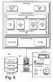
- FIG. 6is a schematic illustration of a computing system, according to an embodiment.
- FIG. 1Ais a schematic, front view of a display assembly, according to an embodiment
- FIG. 1Bis an exploded, side view of a liquid crystal display assembly, according to an embodiment.
- a display assembly 100comprises a base 110 and a monitor assembly 120 coupled to the base.
- Monitor assembly 120comprises a housing 122 , which houses a LCD assembly 150 .
- liquid crystal display assembly 150comprises a controller 152 , a memory module 154 , a backlight assembly 160 , a diffuser/polarizer 168 , a liquid crystal (LC) module 170 , and may include a light directing film 172 .
- Display assembly 100may be embodied as any type of color graphics display.
- LC module 170may comprise a thin film transistor (TFT) assembly.
- the LC module 170may embodied as a different type of LC, e.g., a diode matrix or another capacitively driven LC, a digital mirror assembly, or the like.
- Backlight assembly 160comprises one or more arrays of light emitting diodes (LEDs).
- the one or more arrays of light emitting diodesmay include, e.g., an array of red LEDs 162 , an array of green LEDs 164 , and an array of blue LEDs 166 .
- backlight assembly 160may include one or more reflecting cups 174 positioned adjacent a light emitting diode to reflect light from the diode toward a diffuser 168 positioned adjacent the backlight assembly 160 .
- diffuser 168may also act as a polarizer to polarize light emitted by the arrays of LEDs 162 , 164 , 166 .
- the backlight assemblymay implement alternate illumination techniques.
- the backlight assembly 160may include an array of white LEDs and one or more color filters to generate colors from the white light emitted by the LEDs.
- the backlight assembly 160may include an array of blue LEDs accompanied by a diffusing layer and a photon conversion material to convert the blue light to shades of green and red.
- the backlight assembly 160may include LEDs that generate ultraviolet (UV) radiation and a filter assembly to shift the wavelength of the UV radiation to visible light of varying colors.
- UVultraviolet
- LC module 170is positioned adjacent diffuser 168 .
- LC modulemay be a twisted nematic LC, an in-plane switching LC, or a vertical alignment (VA) LC.
- VAvertical alignment
- a light directing film 172may be positioned adjacent the LC to enhance the brightness of the display.
- a light director 158is disposed adjacent backlight assembly 160 to direct light emitted by the LED arrays 162 , 164 , 166 onto a detector 156 .
- Like director 158may be embodied as a focusing lens, a Fresnel lens, one or more mirrors, one or more light pipes, or a collector such as, for example, in integrating sphere.
- Detector 156generates an electrical signal in response to a characteristic of the light incident upon the detector 156 .
- detector one or 56may be embodied as a photodiode, a quadrant detector, or another suitable optical detector.
- FIGS. 2A and 2Bare schematic illustrations of an illumination timing sequence, according to embodiments.
- the timing sequencemay be managed by the controller 152 .
- FIG. 2Aillustrates a timing sequence for the presentation of a single color image on the LCD assembly 150 .
- the timing controllerimplements a multi-step process to display a full-color image on the LCD assembly 150 .
- the multi-step processsuccessively generates a single color component image of a full-color image, then illuminates the screen with the color component. This process is repeated with each color component of a full-color image.
- the successive single color component imagesappear as a full-color image.
- the LCD assemblyis synchronized at time T 1 .
- a red component of a full-color imageis generated on LCD assembly 150 , and then the array of red LEDs 162 is illuminated.
- a green component of a full-color imageis generated on LCD assembly 150 , and then the array of green LEDs 164 is illuminated.
- a blue component of a full-color imageis generated on LCD assembly 150 , and then the array of blue LEDs 166 is illuminated.
- the combination of the red, green, and blue imagesgenerate a full color image on display assembly 150 .
- the controller 152operates such that each refresh cycle is subdivided into (n+1) different cycles, where n corresponds to the number of component color images presented on the display assembly 150 .
- ncorresponds to the number of component color images presented on the display assembly 150 .
- the 60 Hz refresh ratemay be divided into four different cycles.
- a white illumination cyclemay be added to the backlight assembly, (e.g., by the addition of a white LED array or by the contemporaneous illumination of the red, green, and blue LED arrays) to increase the luminance of the screen, such that each refresh cycle is subdivided into five different cycles.
- FIG. 2Billustrates a timing cycle of controller 152 in an embodiment that utilizes a three-cycle illumination scheme.
- a voltageis applied to the array of red LEDs 162 , then the voltage is removed from array of red LEDs 162 .
- a delayis introduced before a voltage is applied to the array of green LEDs 164 . The voltage is maintained for a time period, then the voltage is removed from array of green LEDs 164 .
- Another delayis introduced before a voltage is applied to the array of blue LEDs 166 .
- the voltageis maintained for a time period, then the voltage is removed from array of blue LEDs 166 .
- Another delay secondis introduced before a voltage is applied to the array of red LEDs 162 , and the cycle continues.
- Other embodiments of the display assemblymay implement illumination timing sequences different from the sequences depicted in FIGS. 2A and 2B .
- a liquid crystal display assemblymay implement techniques to compensate for changes in the optical characteristics of the light emitting diodes used as an illumination source in the display. For example, in some embodiments the display assembly may establish a baseline measurement for one or more optical characteristics of the light emitting diodes when the display assembly is properly calibrated. The optical characteristic measurements may be stored in a memory modules such as, for example, the memory 154 . Subsequently, a recalibration routine may be implemented in which optical characteristic measurements are collected from the light emitting diodes and one or more operating parameters of the light emitting diodes may be adjusted based upon relationship between the optical characteristics collected during the initial baseline measurement and the subsequent recalibration measurement.
- FIGS. 3 and 5are flowcharts illustrating operations in embodiments of a method to operate a display
- FIG. 4is a schematic illustration of a data table, according to embodiments.
- the operations depicted in FIGS. 3 and 5may be implemented by the controller 152 and the data table depicted in FIG. 4 may be stored in the memory module 154 .
- one or more initial operating conditionsare established for the display assembly.
- the display assemblymay be calibrated by using a camera or charge coupled device (CCD) coupled to a computing device to view the display.
- CCDcharge coupled device
- One or more operating parameters associated with the light emitting diodesmay be adjusted until the display assembly exhibits a desired color temperature (e.g., 6500K).
- the controllermaintains a data table 400 ( FIG. 4 ) in memory module 154 .
- the data table 400may be organized as a series of columns and rows.
- the table 400may include a row for each light emitting diode.
- each light emitting diodemay be uniquely identified by its Cartesian coordinate position (x,y) in the array of light emitting diodes.
- data table 400includes an entry for the operating voltage of each light emitting diode.
- the operating voltage for a plurality of light emitting diodes, and in some embodiments for each light emitting diode, in the displayis recorded in the data table 400 .
- an output parameter of one or more light emitting diodesis measured using an integrated detector, such as the detector 156 .
- each light emitting diode in the LCD assembly 150is a separately addressable by the controller 152 .
- the controllermay activate individual light emitting diodes, applying the voltage V(T 0 ) depicted in FIG. 4 to the diode.
- an output parameter from the light emitting diodeis recorded in the data table 400 .
- the detector 156produces an output signal, such as an output voltage VD(T 0 ) in response to an optical input from the light emitting diode.
- the output voltage associated with each light emitting diode when operated at the initial calibration voltageis recorded in the data table 400 .
- the data table 400provides a correlation between the driving voltage of each light emitting diode and an output signal generated by the detector 156 in response to the driving voltage.
- FIG. 5depicts operations in a process that may be used to recalibrate the liquid crystal display.
- the recalibration processis initiated.
- the recalibration processmay be initiated by a user through a user interface, such as, for example to a software interface or a hardware interface coupled to the liquid crystal display assembly 150 .
- the recalibration processmay be implemented periodically through time.
- the recalibration processmay be implemented based on temperature variation in the region proximate the liquid crystal display assembly 150 .
- a thermocouple or other thermoelectric detection devicemay detect when a change in temperature in the liquid crystal device assembly exceeds a threshold and may trigger a recalibration process in response to the temperature change.
- one or more output parameters associated with the light emitting diodesare measured using the integrated detector 156 .
- each light emitting diode in the LCD assembly 150is a separately addressable by the controller 152 .
- the controllermay activate individual light emitting diodes, again applying the voltage V(T 0 ) depicted in FIG. 4 to the diode.
- an output parameter from the light emitting diodeis measured.
- the detector 156produces an output signal, such as an output voltage VD(T R ) in response to an optical input from the light emitting diode.
- the output voltage associated with each light emitting diode when operated at the initial calibration voltagemay be recorded in the data table 400 .
- one or more operating parameters associated with the light emitting diodeis adjusted. For example, using the embodiment depicted in FIG. 4 , is the difference between the output detector voltage measured during the calibration process and the output detector voltage measured during the recalibration process exceeds a threshold than the operating voltage of the light emitting diode may be adjusted.
- the operating voltagemay be adjusted as a function of a difference between the output voltage generated by the detector 156 .
- the operating voltage of the light emitting diodemay be adjusted as by a factor of the ratio of the voltages measured during the initial calibration process and the recalibration process, respectively.
- V newV(T 0 )*(VD(T 0 )/VD(T R )).
- a quadratic approximation techniquemay be applied.
- controlpasses to operation 535 in the controller activates a next light emitting diode in the array.
- Controlin passes back to operation 515 in the selected light emitting diode is evaluated.
- operations 515 through 535may be repeated in a loop such that all light emitting diodes in the array, or a subset thereof, may be evaluated and if necessary adjusted during the recalibration process.
- a liquid crystal display assembly 150may be distributed as a component of a computer system.
- FIG. 6is a schematic illustration of a computing system, according to an embodiment. The components shown in FIG. 6 are only examples, and are not intended to suggest any limitation as to the scope of the functionality of the display assembly; the display assembly is not necessarily dependent on the features shown in FIG. 6 .
- computer system 600may be embodied as a hand-held or stationary device for accessing the Internet, a desktop PCs, notebook computer, personal digital assistant, or any other processing devices that have a basic input/output system (BIOS) or equivalent.
- BIOSbasic input/output system
- the computing system 600includes a computer 608 and one or more accompanying input/output devices 606 including a display 602 having a screen 604 , a keyboard 610 , other I/O device(s) 612 , and a mouse 614 .
- the other device(s) 612may include, for example, a touch screen, a voice-activated input device, a track ball, and any other device that allows the system 600 to receive input from a developer and/or a user.
- the computer 608includes system hardware 620 commonly implemented on a motherboard and at least one auxiliary circuit boards.
- System hardware 620including a processor 622 and a basic input/output system (BIOS) 626 .
- BIOS 626may be implemented in flash memory and may comprise logic operations to boot the computer device and a power-on self-test (POST) module for performing system initialization and tests.
- POSTpower-on self-test
- processor 622accesses BIOS 626 and shadows the instructions of BIOS 626 , such as power-on self-test module, into operating memory.
- Processor 622executes power-on self-test operations to implement POST processing.
- Computer system 600further includes a file store 680 communicatively connected to computer 608 .
- File store 680may be internal such as, e.g., one or more hard drives, or external such as, e.g., one or more external hard drives, network attached storage, or a separate storage network.
- the file store 680may include one or more partitions 682 , 684 , 686 .
- Memory 630includes an operating system 640 for managing operations of computer 608 .
- operating system 640includes a hardware interface module 654 that provides an interface to system hardware 620 .
- operating system 640includes a kernel 644 , one or more file systems 646 that manage files used in the operation of computer 608 and a process control subsystem 648 that manages processes executing on computer 608 .
- Operating system 640further includes one or more device drivers 650 and a system call interface module 642 that provides an interface between the operating system 640 and one or more application modules 662 and/or libraries 664 .
- the various device drivers 650interface with and generally control the hardware installed in the computing system 600 .
- one or more application modules 662 and/or libraries 664 executing on computer 608make calls to the system call interface module 642 to execute one or more commands on the computer's processor.
- the system call interface module 642invokes the services of the file systems 646 to manage the files required by the command(s) and the process control subsystem 648 to manage the process required by the command(s).
- the file system(s) 646 and the process control subsystem 648invoke the services of the hardware interface module 654 to interface with the system hardware 620 .
- the operating system kernel 644can be generally considered as one or more software modules that are responsible for performing many operating system functions.
- Operating system 640may be embodied as a UNIX operating system or any derivative thereof (e.g., Linux, Solaris, etc.) or as a Windows® brand operating system or another operating system.
Landscapes
- Physics & Mathematics (AREA)
- Nonlinear Science (AREA)
- General Physics & Mathematics (AREA)
- Chemical & Material Sciences (AREA)
- Mathematical Physics (AREA)
- Crystallography & Structural Chemistry (AREA)
- Engineering & Computer Science (AREA)
- Optics & Photonics (AREA)
- Theoretical Computer Science (AREA)
- Computer Hardware Design (AREA)
- Liquid Crystal Display Device Control (AREA)
- Control Of Indicators Other Than Cathode Ray Tubes (AREA)
- Liquid Crystal (AREA)
Abstract
Description
Claims (20)
Priority Applications (5)
| Application Number | Priority Date | Filing Date | Title |
|---|---|---|---|
| US11/888,004US8259057B2 (en) | 2007-07-31 | 2007-07-31 | Liquid crystal display |
| PCT/US2008/008270WO2009017568A2 (en) | 2007-07-31 | 2008-07-03 | Liquid crystal display |
| CN2008801013730ACN101779156B (en) | 2007-07-31 | 2008-07-03 | Liquid crystal display |
| KR1020107002260AKR101456687B1 (en) | 2007-07-31 | 2008-07-03 | Liquid crystal display |
| TW097125262ATWI446068B (en) | 2007-07-31 | 2008-07-04 | Liquid crystal display |
Applications Claiming Priority (1)
| Application Number | Priority Date | Filing Date | Title |
|---|---|---|---|
| US11/888,004US8259057B2 (en) | 2007-07-31 | 2007-07-31 | Liquid crystal display |
Publications (2)
| Publication Number | Publication Date |
|---|---|
| US20090033613A1 US20090033613A1 (en) | 2009-02-05 |
| US8259057B2true US8259057B2 (en) | 2012-09-04 |
Family
ID=40305094
Family Applications (1)
| Application Number | Title | Priority Date | Filing Date |
|---|---|---|---|
| US11/888,004Expired - Fee RelatedUS8259057B2 (en) | 2007-07-31 | 2007-07-31 | Liquid crystal display |
Country Status (5)
| Country | Link |
|---|---|
| US (1) | US8259057B2 (en) |
| KR (1) | KR101456687B1 (en) |
| CN (1) | CN101779156B (en) |
| TW (1) | TWI446068B (en) |
| WO (1) | WO2009017568A2 (en) |
Families Citing this family (6)
| Publication number | Priority date | Publication date | Assignee | Title |
|---|---|---|---|---|
| CN101551979A (en)* | 2008-04-03 | 2009-10-07 | 上海天马微电子有限公司 | Outdoor readable liquid crystal display device |
| TWM364241U (en)* | 2008-11-28 | 2009-09-01 | Tron Intelligence Inc | Optical sensing type input device |
| US8156641B2 (en)* | 2009-05-21 | 2012-04-17 | Xerox Corporation | Interconnection method for tightly packed arrays with flex circuit |
| JP6436336B2 (en)* | 2014-02-13 | 2018-12-12 | Tianma Japan株式会社 | Backlight light source device and liquid crystal display device |
| FR3032552A1 (en)* | 2015-02-11 | 2016-08-12 | Peugeot Citroen Automobiles Sa | VEHICLE LIGHT DEVICE AND METHOD FOR CONTROLLING SUCH A DEVICE |
| KR101962236B1 (en)* | 2017-09-19 | 2019-07-17 | (주)파트론 | Optical sensor package |
Citations (22)
| Publication number | Priority date | Publication date | Assignee | Title |
|---|---|---|---|---|
| US6127783A (en)* | 1998-12-18 | 2000-10-03 | Philips Electronics North America Corp. | LED luminaire with electronically adjusted color balance |
| US20020057238A1 (en)* | 2000-09-08 | 2002-05-16 | Hiroyuki Nitta | Liquid crystal display apparatus |
| US6495964B1 (en)* | 1998-12-18 | 2002-12-17 | Koninklijke Philips Electronics N.V. | LED luminaire with electrically adjusted color balance using photodetector |
| US6611249B1 (en)* | 1998-07-22 | 2003-08-26 | Silicon Graphics, Inc. | System and method for providing a wide aspect ratio flat panel display monitor independent white-balance adjustment and gamma correction capabilities |
| US6633301B1 (en) | 1999-05-17 | 2003-10-14 | Displaytech, Inc. | RGB illuminator with calibration via single detector servo |
| JP2006019263A (en) | 2004-06-30 | 2006-01-19 | Agilent Technol Inc | Light source calibration |
| JP2006119268A (en) | 2004-10-20 | 2006-05-11 | Nec Display Solutions Ltd | Back light adjusting system, program, and recording medium |
| US7071908B2 (en)* | 2003-05-20 | 2006-07-04 | Kagutech, Ltd. | Digital backplane |
| US20070063961A1 (en)* | 2004-07-21 | 2007-03-22 | Sony Corporation | Display apparatus and method, storage medium, and program |
| CN1945405A (en) | 2005-10-07 | 2007-04-11 | 夏普株式会社 | Backlight device, display device including same, driving method and adjustment method of backlight device |
| KR20070045735A (en) | 2005-10-28 | 2007-05-02 | 삼성전자주식회사 | Display apparatus having backlight having LED as light source, and method of adjusting brightness thereof |
| US20070120496A1 (en)* | 2003-07-28 | 2007-05-31 | Yoshinori Shimizu | Light emitting apparatus, led lighting, led light emitting apparatus, and control method of light emitting apparatus |
| US20070182700A1 (en)* | 2006-02-06 | 2007-08-09 | Kabushiki Kaisha Toshiba | Image display device and image display method |
| US20070247414A1 (en)* | 2006-04-21 | 2007-10-25 | Cree, Inc. | Solid state luminaires for general illumination |
| KR20080056618A (en) | 2006-12-18 | 2008-06-23 | 엘지디스플레이 주식회사 | LED backlight system and its initial setting method |
| US20080165116A1 (en)* | 2007-01-05 | 2008-07-10 | Herz Scott M | Backlight and Ambient Light Sensor System |
| US7408557B2 (en)* | 2002-09-13 | 2008-08-05 | Samsung Electronics Co., Ltd. | Apparatus and method for adjusting brightness and color temperature |
| US7542056B2 (en)* | 2002-09-30 | 2009-06-02 | Lg Electronics Inc. | Method for controlling brightness level of a display |
| US7759882B2 (en)* | 2006-07-31 | 2010-07-20 | Microsemi Corp.—Analog Mixed Signal Group Ltd. | Color control for scanning backlight |
| US7884832B2 (en)* | 2007-04-13 | 2011-02-08 | Global Oled Technology Llc | Calibrating RGBW displays |
| US7889235B2 (en)* | 2005-11-24 | 2011-02-15 | Funai Electric Co., Ltd. | Liquid crystal television adjustment system, liquid crystal display unit adjustment system, and liquid crystal display unit |
| US7893916B2 (en)* | 2007-04-13 | 2011-02-22 | Novatek Microelectronics Corp. | Luminance compensation device and method thereof for backlight module |
Family Cites Families (2)
| Publication number | Priority date | Publication date | Assignee | Title |
|---|---|---|---|---|
| JP4753661B2 (en) | 2005-08-16 | 2011-08-24 | シャープ株式会社 | Display device |
| JP2008009090A (en) | 2006-06-28 | 2008-01-17 | Sharp Corp | Liquid crystal display |
- 2007
- 2007-07-31USUS11/888,004patent/US8259057B2/ennot_activeExpired - Fee Related
- 2008
- 2008-07-03WOPCT/US2008/008270patent/WO2009017568A2/enactiveApplication Filing
- 2008-07-03KRKR1020107002260Apatent/KR101456687B1/ennot_activeExpired - Fee Related
- 2008-07-03CNCN2008801013730Apatent/CN101779156B/ennot_activeExpired - Fee Related
- 2008-07-04TWTW097125262Apatent/TWI446068B/ennot_activeIP Right Cessation
Patent Citations (24)
| Publication number | Priority date | Publication date | Assignee | Title |
|---|---|---|---|---|
| US6611249B1 (en)* | 1998-07-22 | 2003-08-26 | Silicon Graphics, Inc. | System and method for providing a wide aspect ratio flat panel display monitor independent white-balance adjustment and gamma correction capabilities |
| CN1291282A (en) | 1998-12-18 | 2001-04-11 | 皇家菲利浦电子有限公司 | Luminous diode lighting device |
| US6495964B1 (en)* | 1998-12-18 | 2002-12-17 | Koninklijke Philips Electronics N.V. | LED luminaire with electrically adjusted color balance using photodetector |
| US6127783A (en)* | 1998-12-18 | 2000-10-03 | Philips Electronics North America Corp. | LED luminaire with electronically adjusted color balance |
| US6633301B1 (en) | 1999-05-17 | 2003-10-14 | Displaytech, Inc. | RGB illuminator with calibration via single detector servo |
| US20020057238A1 (en)* | 2000-09-08 | 2002-05-16 | Hiroyuki Nitta | Liquid crystal display apparatus |
| US7408557B2 (en)* | 2002-09-13 | 2008-08-05 | Samsung Electronics Co., Ltd. | Apparatus and method for adjusting brightness and color temperature |
| US7542056B2 (en)* | 2002-09-30 | 2009-06-02 | Lg Electronics Inc. | Method for controlling brightness level of a display |
| US7071908B2 (en)* | 2003-05-20 | 2006-07-04 | Kagutech, Ltd. | Digital backplane |
| US20070120496A1 (en)* | 2003-07-28 | 2007-05-31 | Yoshinori Shimizu | Light emitting apparatus, led lighting, led light emitting apparatus, and control method of light emitting apparatus |
| JP2006019263A (en) | 2004-06-30 | 2006-01-19 | Agilent Technol Inc | Light source calibration |
| US20070063961A1 (en)* | 2004-07-21 | 2007-03-22 | Sony Corporation | Display apparatus and method, storage medium, and program |
| JP2006119268A (en) | 2004-10-20 | 2006-05-11 | Nec Display Solutions Ltd | Back light adjusting system, program, and recording medium |
| CN1945405A (en) | 2005-10-07 | 2007-04-11 | 夏普株式会社 | Backlight device, display device including same, driving method and adjustment method of backlight device |
| US20070097045A1 (en)* | 2005-10-28 | 2007-05-03 | Samsung Electronics Co., Ltd. | Display apparatus having LED backlight and brightness adjusting method for the same |
| KR20070045735A (en) | 2005-10-28 | 2007-05-02 | 삼성전자주식회사 | Display apparatus having backlight having LED as light source, and method of adjusting brightness thereof |
| US7889235B2 (en)* | 2005-11-24 | 2011-02-15 | Funai Electric Co., Ltd. | Liquid crystal television adjustment system, liquid crystal display unit adjustment system, and liquid crystal display unit |
| US20070182700A1 (en)* | 2006-02-06 | 2007-08-09 | Kabushiki Kaisha Toshiba | Image display device and image display method |
| US20070247414A1 (en)* | 2006-04-21 | 2007-10-25 | Cree, Inc. | Solid state luminaires for general illumination |
| US7759882B2 (en)* | 2006-07-31 | 2010-07-20 | Microsemi Corp.—Analog Mixed Signal Group Ltd. | Color control for scanning backlight |
| KR20080056618A (en) | 2006-12-18 | 2008-06-23 | 엘지디스플레이 주식회사 | LED backlight system and its initial setting method |
| US20080165116A1 (en)* | 2007-01-05 | 2008-07-10 | Herz Scott M | Backlight and Ambient Light Sensor System |
| US7884832B2 (en)* | 2007-04-13 | 2011-02-08 | Global Oled Technology Llc | Calibrating RGBW displays |
| US7893916B2 (en)* | 2007-04-13 | 2011-02-22 | Novatek Microelectronics Corp. | Luminance compensation device and method thereof for backlight module |
Non-Patent Citations (3)
| Title |
|---|
| Chinese. Office Action, Chinese Patent Application No. 200880101373.0, Date of Issuance: May 18, 2011, pp. 1-4. |
| International Search Report and the Written Opinion, dated Jan. 30, 2009, 11 pages. |
| State Intellectual Property Office, P.R. China. Second Office Action. Date of Issue Dec. 7, 2011. Patent Application No. 200880101373.0. |
Also Published As
| Publication number | Publication date |
|---|---|
| KR20100049571A (en) | 2010-05-12 |
| CN101779156A (en) | 2010-07-14 |
| TW200912477A (en) | 2009-03-16 |
| KR101456687B1 (en) | 2014-10-31 |
| US20090033613A1 (en) | 2009-02-05 |
| WO2009017568A3 (en) | 2009-03-12 |
| CN101779156B (en) | 2013-04-03 |
| TWI446068B (en) | 2014-07-21 |
| WO2009017568A2 (en) | 2009-02-05 |
Similar Documents
| Publication | Publication Date | Title |
|---|---|---|
| US8259057B2 (en) | Liquid crystal display | |
| JP6700044B2 (en) | Display device | |
| US10019112B2 (en) | Touch panels with dynamic zooming and low profile bezels | |
| US8115726B2 (en) | Liquid crystal display image presentation | |
| US20180120614A1 (en) | Display panel and display device | |
| US20090122030A1 (en) | Display system and method for detecting pointed position | |
| US9934731B2 (en) | Multiple backlight display system | |
| CN101464187A (en) | Light sensor test unit, method of testing light sensor using the same and display apparatus | |
| KR20070017695A (en) | Display device and driving method thereof | |
| US11249343B2 (en) | Display device comprising an illumination device having a light diffusion layer exhibiting a first diffusion degree in a first direction which is different than a second diffusion degree in a second direction | |
| US11538424B2 (en) | Self-calibrating illumination modules for display backlight | |
| KR20160056386A (en) | Display apparatus | |
| US20110012943A1 (en) | Liquid Crystal Display Uniformity | |
| KR20160116162A (en) | Display apparatus | |
| CN111290069A (en) | Liquid crystal display device having a plurality of pixel electrodes | |
| US20190196273A1 (en) | Display apparatus and method for control thereof | |
| US20190041983A1 (en) | Display With Pixel Level Eye Tracking | |
| CN110286518B (en) | Display module, control method thereof and display device | |
| TWI385369B (en) | Measurement method and display | |
| US20080224974A1 (en) | Liquid crystal display | |
| JP2007072243A (en) | Illuminance detecting method, luminance control method, electrooptical device, and electronic equipment | |
| Milton | Small is Beautiful | |
| Meyer et al. | Reflective display characterization: temporal and spatial viewability measurements of holographic polymer-dispersed liquid crystal (HPDLC) display samples | |
| US20050280358A1 (en) | Light-polarizing film with high permeability for improving an interference light of a color organic light emitting diode |
Legal Events
| Date | Code | Title | Description |
|---|---|---|---|
| AS | Assignment | Owner name:HEWLETT-PACKARD DEVELOPMENT COMPANY, L.P., TEXAS Free format text:ASSIGNMENT OF ASSIGNORS INTEREST;ASSIGNOR:BUTTERWORTH, MARK;REEL/FRAME:019789/0938 Effective date:20070904 | |
| ZAAA | Notice of allowance and fees due | Free format text:ORIGINAL CODE: NOA | |
| ZAAB | Notice of allowance mailed | Free format text:ORIGINAL CODE: MN/=. | |
| STCF | Information on status: patent grant | Free format text:PATENTED CASE | |
| CC | Certificate of correction | ||
| FPAY | Fee payment | Year of fee payment:4 | |
| MAFP | Maintenance fee payment | Free format text:PAYMENT OF MAINTENANCE FEE, 8TH YEAR, LARGE ENTITY (ORIGINAL EVENT CODE: M1552); ENTITY STATUS OF PATENT OWNER: LARGE ENTITY Year of fee payment:8 | |
| FEPP | Fee payment procedure | Free format text:MAINTENANCE FEE REMINDER MAILED (ORIGINAL EVENT CODE: REM.); ENTITY STATUS OF PATENT OWNER: LARGE ENTITY | |
| LAPS | Lapse for failure to pay maintenance fees | Free format text:PATENT EXPIRED FOR FAILURE TO PAY MAINTENANCE FEES (ORIGINAL EVENT CODE: EXP.); ENTITY STATUS OF PATENT OWNER: LARGE ENTITY | |
| STCH | Information on status: patent discontinuation | Free format text:PATENT EXPIRED DUE TO NONPAYMENT OF MAINTENANCE FEES UNDER 37 CFR 1.362 | |
| FP | Lapsed due to failure to pay maintenance fee | Effective date:20240904 |