US8257396B2 - Polyaxial bone screw with shank-retainer inset capture - Google Patents
Polyaxial bone screw with shank-retainer inset captureDownload PDFInfo
- Publication number
- US8257396B2 US8257396B2US12/154,460US15446008AUS8257396B2US 8257396 B2US8257396 B2US 8257396B2US 15446008 AUS15446008 AUS 15446008AUS 8257396 B2US8257396 B2US 8257396B2
- Authority
- US
- United States
- Prior art keywords
- receiver
- shank
- upper portion
- retainer
- section
- Prior art date
- Legal status (The legal status is an assumption and is not a legal conclusion. Google has not performed a legal analysis and makes no representation as to the accuracy of the status listed.)
- Active, expires
Links
Images


Classifications
- A—HUMAN NECESSITIES
- A61—MEDICAL OR VETERINARY SCIENCE; HYGIENE
- A61B—DIAGNOSIS; SURGERY; IDENTIFICATION
- A61B17/00—Surgical instruments, devices or methods
- A61B17/56—Surgical instruments or methods for treatment of bones or joints; Devices specially adapted therefor
- A61B17/58—Surgical instruments or methods for treatment of bones or joints; Devices specially adapted therefor for osteosynthesis, e.g. bone plates, screws or setting implements
- A61B17/68—Internal fixation devices, including fasteners and spinal fixators, even if a part thereof projects from the skin
- A61B17/70—Spinal positioners or stabilisers, e.g. stabilisers comprising fluid filler in an implant
- A61B17/7001—Screws or hooks combined with longitudinal elements which do not contact vertebrae
- A61B17/7035—Screws or hooks, wherein a rod-clamping part and a bone-anchoring part can pivot relative to each other
- A61B17/7037—Screws or hooks, wherein a rod-clamping part and a bone-anchoring part can pivot relative to each other wherein pivoting is blocked when the rod is clamped
- A—HUMAN NECESSITIES
- A61—MEDICAL OR VETERINARY SCIENCE; HYGIENE
- A61B—DIAGNOSIS; SURGERY; IDENTIFICATION
- A61B17/00—Surgical instruments, devices or methods
- A61B17/56—Surgical instruments or methods for treatment of bones or joints; Devices specially adapted therefor
- A61B17/58—Surgical instruments or methods for treatment of bones or joints; Devices specially adapted therefor for osteosynthesis, e.g. bone plates, screws or setting implements
- A61B17/68—Internal fixation devices, including fasteners and spinal fixators, even if a part thereof projects from the skin
- A61B17/70—Spinal positioners or stabilisers, e.g. stabilisers comprising fluid filler in an implant
- A61B17/7001—Screws or hooks combined with longitudinal elements which do not contact vertebrae
- A61B17/7032—Screws or hooks with U-shaped head or back through which longitudinal rods pass
- A—HUMAN NECESSITIES
- A61—MEDICAL OR VETERINARY SCIENCE; HYGIENE
- A61B—DIAGNOSIS; SURGERY; IDENTIFICATION
- A61B17/00—Surgical instruments, devices or methods
- A61B17/56—Surgical instruments or methods for treatment of bones or joints; Devices specially adapted therefor
- A61B17/58—Surgical instruments or methods for treatment of bones or joints; Devices specially adapted therefor for osteosynthesis, e.g. bone plates, screws or setting implements
- A61B17/68—Internal fixation devices, including fasteners and spinal fixators, even if a part thereof projects from the skin
- A61B17/84—Fasteners therefor or fasteners being internal fixation devices
- A61B17/86—Pins or screws or threaded wires; nuts therefor
- A—HUMAN NECESSITIES
- A61—MEDICAL OR VETERINARY SCIENCE; HYGIENE
- A61B—DIAGNOSIS; SURGERY; IDENTIFICATION
- A61B2560/00—Constructional details of operational features of apparatus; Accessories for medical measuring apparatus
- A61B2560/04—Constructional details of apparatus
- A61B2560/0406—Constructional details of apparatus specially shaped apparatus housings
Definitions
- the present inventionis directed to polyaxial bone screws for use in bone surgery, particularly spinal surgery, and particularly to capture structures and inserts for such screws.
- Bone screwsare utilized in many types of spinal surgery in order to secure various implants to vertebrae along the spinal column for the purpose of stabilizing and/or adjusting spinal alignment.
- closed-ended and open-ended bone screwsare known
- open-ended screwsare particularly well suited for connections to rods and connector arms, because such rods or arms do not need to be passed through a closed bore, but rather can be laid or urged into an open channel within a receiver or head of such a screw.
- Typical open-ended bone screwsinclude a threaded shank with a pair of parallel projecting branches or arms which form a yoke with a U-shaped slot or channel to receive a rod.
- Hooks and other types of connectorsas are used in spinal fixation techniques, may also include open ends for receiving rods or portions of other structure.
- Bone screws of this typemay have a fixed head or receiver relative to a shank thereof.
- the rod receiver headcannot be moved relative to the shank and the rod must be favorably positioned in order for it to be placed within the receiver head. This is sometimes very difficult or impossible to do. Therefore, polyaxial bone screws are commonly preferred.
- Open-ended polyaxial bone screwsallow rotation of the head or receiver about the shank until a desired rotational position of the head is achieved relative to the shank. Thereafter, a rod can be inserted into the head or receiver and eventually the receiver is locked or fixed in a particular position relative to the shank.
- some bone screwsdesirably include compression inserts or other parts that are designed to securely and fully engage surface portions of a rod or other longitudinal connecting member.
- a polyaxial bone screw assembly of the present inventionincludes a shank having a generally elongate body with an upper end portion a neck below the upper end portion and a lower threaded portion for fixation to a bone.
- the upper end portionincludes at least first and second surfaces, the second surface being at least partially inset or at least a portion thereof spaced inwardly from the first surface.
- the first and second surfacesmay be in the form of two substantially cylindrical surface portions of different widths or diameters or a cylindrical surface portion and a conical surface portion that is inset from the cylindrical surface portion.
- the upper end portionmay include a laterally extending alignment structure in the form of a fin, rib or lug that can at least partially fill a gap or slot in a retainer component and block rotation between these two parts.
- the bone screw assemblyfurther includes a lockable receiver coupling member having a top portion and a base.
- the top portionis open and has a channel.
- the baseincludes an inner surface partially defining a cavity and a lower aperture or opening to an exterior of the base.
- the channel of the top portioncommunicates with the cavity, which in turn communicates with the base lower opening; such opening is sized and shaped to receive the shank upper end portion into the receiver cavity.
- the partsare arranged such that the shank neck is in close alignment with and positioned directly below the receiver cavity.
- the bone screw assemblyalso includes an open ring-like retainer structure defining a gap or slit and further having a discontinuous internal surface sized and shaped to be received over the lower conical or cylindrical surface portion to capture, house and hold the retainer and shank upper end portion within the lockable receiver coupling member.
- the fin of the shank upper portionis disposed within the gap or slit of the retainer structure.
- the external surface of the retainer structureis configured to be in slidable, pivotable engagement with a seating surface defining a portion of the cavity of the receiver.
- the retainer structure external surface and the mating receiver inner seating surfaceare substantially spherical.
- the mating surfacesmay be of another shape, such as conical, cylindrical or tapered, especially for the receiver cavity inner seating surface.
- the cooperating shapes of the retainer external surface and the receiver seating surfaceenable selective angular positioning of the shank body with respect to the receiver.
- the illustrated bone screw assemblyfurther includes a compression or pressure insert disposed between the shank upper portion and a longitudinal connecting member, such as a rod, being held in place by the bone screw.
- An upper or top surface of the shank upper end portionis sized and shaped for frictionally engagement with a lower surface of the pressure insert.
- the shank upper portionincludes a tool engagement formation with an internal drive.
- the shank upper top surfacecan include knurling and the shank upper portion is sized in axial length such that the shank upper surface engages the compression insert at a location substantially spaced from the retainer structure.
- the compression insertis always spaced from the retainer structure and never engages the same, advantageously providing for the exertion of pressure exclusively onto the stronger integral shank upper portion.
- the retainer structure of the present inventionis split and thus could become twisted or mis-aligned if placed under the opposing shear forces and even torsional forces caused if the pressure insert were allowed to press upon an edge or surface of the retainer structure when it is in a pivoted, angled or oblique position.
- the shank upper end portionincludes an axially directed length adequate to prevent such undesirable engagement between the pressure insert and the retainer structure.
- the retainer structureis advantageously disposed substantially below the pressure insert and between the shank upper portion and the receiver seating surface, with only the shank upper portion pressing the retainer structure against the receiver seating surface.
- objects of the inventioninclude: providing a polyaxial bone screw having a shank with off-set surfaces that cooperate with a retaining structure that is configured with inset capture surfaces for retaining an upper portion of the shank in a lockable bone screw receiver coupling member and also configured for polyaxial motion with respect to the receiver prior to locking; providing such a polyaxial bone screw that includes a pressure insert that exerts pressure exclusively on the integral and stronger shank upper end portion and that is substantially spaced from the retaining structure; providing a lightweight, low profile polyaxial bone screw that assembles in such a manner that the components cooperate to create an overall structure that prevents unintentional disassembly; providing a polyaxial bone screw with features that provide adequate frictional or gripping surfaces for bone implantation tools and may be readily, securely fastened to each other and to bone; and providing apparatus and methods that are easy to use and especially adapted for the intended use thereof and wherein the apparatus are comparatively inexpensive to make and suitable for use.
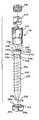
- FIG. 1is an exploded perspective view of a polyaxial bone screw assembly according to the present invention having a shank, a receiver, a retainer and a compression insert and further shown with a closure structure.
- FIG. 2is an enlarged front elevational view of the shank of FIG. 1 .
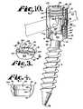
- FIG. 3is an enlarged perspective view of the retainer of FIG. 1 .
- FIG. 4is an enlarged cross-sectional view taken along the line 4 - 4 of FIG. 3 .
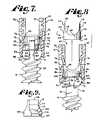
- FIG. 5is an enlarged and partial exploded front elevational view of the shank, retainer and receiver of FIG. 1 with portions broken away to show the detail thereof showing the shank and retainer in a first stage of assembly.
- FIG. 6is an enlarged and partial front elevational view similar to FIG. 5 showing the shank being uploaded into the retainer in a subsequent stage of assembly.
- FIG. 7is an enlarged and partial front elevational view similar to FIG. 6 showing a subsequent stage of assembly.
- FIG. 8is an enlarged and partial front elevational view similar to FIG. 7 and also including the compression insert, showing a subsequent stage of assembly.
- FIG. 9is an enlarged side elevational view of the compression insert of FIG. 1 with portions broken away to show the detail thereof.
- FIG. 10is an enlarged perspective view of the assembly of FIG. 1 shown assembled with a rod and with portions broken away to show the detail thereof.
- FIG. 11is an exploded perspective view of a second embodiment of a polyaxial bone screw assembly according to the present invention having a shank, a receiver, a retainer and a compression insert and further shown with a closure structure.
- FIG. 12is an enlarged perspective view of the retainer of FIG. 11 .
- FIG. 13is an enlarged cross-sectional view taken along the line 13 - 13 of FIG. 12 .
- FIG. 14is an enlarged perspective view of the assembly of FIG. 11 shown assembled with a rod and with portions broken away to show the detail thereof.
- the reference number 1generally represents an embodiment of a polyaxial bone screw apparatus or assembly according to the present invention.
- the assembly 1includes a shank 4 that further includes a threaded body 6 integral with an upper portion 8 ; a receiver 10 ; an open retainer structure or ring 12 ; and a compression insert 14 .
- the shank 4 , receiver 10 , retainer structure 12 , and compression insert 14preferably are factory assembled prior to implantation of the shank body 6 into a vertebra (not shown).
- a closure structure 18for biasing a longitudinal connecting member such as a rod 21 having a cylindrical surface 22 against the compression insert 14 that in turn presses upon the shank upper portion 8 which biases the retainer 12 into fixed frictional contact with the receiver 10 , so as to fix the rod 21 relative to the vertebra (not shown).
- the receiver 10 and the shank 4cooperate in such a manner that the receiver 10 and the shank 4 can be secured at any of a plurality of angles, articulations or pivotal alignments relative to one another and within a selected range of angles both from side to side and from front to rear, to enable flexible or articulated engagement of the receiver 10 with the shank 4 until both are locked or fixed relative to each other near the end of an implantation procedure.
- the shank 4is elongate, with the shank body 6 having a helically wound bone implantable thread 24 extending from near a neck 26 located adjacent to the upper portion 8 to a tip 28 of the body 6 and extending radially outwardly therefrom.
- the body 6utilizing the thread 24 for gripping and advancement is implanted into the vertebra (not shown) leading with the tip 28 and driven down into the vertebra with an installation or driving tool, so as to be implanted in the vertebra to near the neck 26 , and as is described more fully in the paragraphs below.
- the shank 4has an elongate axis of rotation generally identified by the reference letter A.
- the neck 26extends axially upwardly from the shank body 6 .
- the neck 26may be of reduced radius as compared to an adjacent top 32 of the threaded body 6 .
- the shank upper portion 8Further extending axially upwardly from the neck 26 is the shank upper portion 8 that provides a connective or capture apparatus disposed at a distance from the threaded body top 32 and thus at a distance from the vertebra when the body 6 is implanted in the vertebra.
- the shank upper portion 8is configured for a polyaxial connection between the shank 4 and the receiver 10 and capturing the shank 4 upper portion 8 in the receiver 10 .
- the illustrated upper portion 8generally includes an outer conical surface portion 33 located adjacent the neck 26 ; an annular planar retainer seat portion 34 ; a substantially cylindrical surface portion 35 ; a curved and annular upper surface 36 and a planar top surface 38 .
- the planar top surface 38is substantially perpendicular to the cylindrical surface portion 35 and substantially parallel to the seat portion 34 . As shown in the drawings and described more fully below, the height of the portion 35 along the axis A ensures that the cooperating lower pressure insert 14 is separated from and never engages the retainer 12 throughout a full range of polyaxial motion of the assembly 1 in all directions.
- the conical portion 33extends between the neck 26 and the retainer seat 34 .
- the retainer seat 34defines a lower edge 39 of the cylindrical portion 35 .
- a structure in the form of a rib or fin 40extends laterally from the conical portion 33 and a lower part of the cylindrical portion 35 .
- a tool engagement internal drive feature or structure 42is formed in the top end surface 38 .
- a driving tool(not shown) has a driving projection configured to fit within the tool engagement structure 42 for both driving and rotating the shank body 6 into the vertebra.
- the upper surface 36 of the shank 4is preferably curved or radiused as shown in the drawings, for contact engagement or positive mating engagement with the compression insert 14 , when the bone screw assembly 1 is assembled, as shown in FIG. 10 and in any pivotal alignment of the shank 4 relative to the receiver 10 .
- the illustrated surface 36also has approximately the same radius as an inner spherical seating surface of the receiver 10 , allowing for clearance of the shank 4 with respect to the receiver 10 and thus a desired degree and magnitude of articulation of the shank 4 with respect to the receiver 10 , as will be described in greater detail below.
- the surface 36is smooth. While not required in accordance with the practice of the invention, the surface 36 may be scored or knurled to further increase frictional positive mating engagement between the surface 36 and the compression insert 14 .
- the shank 4 shown in the drawingsis cannulated, having a small central bore 44 extending an entire length of the shank 4 along the axis A.
- the bore 44is defined by an inner cylindrical wall of the shank 4 and has a circular opening 46 at the shank tip 28 and an upper opening communicating with the internal drive 42 .
- the bore 44is coaxial with the threaded body 6 and the upper portion 8 .
- the bore 44provides a passage through the shank 4 interior for a length of wire (not shown) inserted into the vertebra (not shown) prior to the insertion of the shank body 6 , the wire providing a guide for insertion of the shank body 6 into the vertebra (not shown).
- the retainer seat 34 of the shank upper portion 8is formed by the off-set positioning and cooperation of the surface portions 33 and 35 .
- the off-set nature of the surface portion 35 with respect to the surface portion 33creates the surface 34 that is substantially planar, annular and disposed perpendicular to the axis A of the shank and sized and shaped to engage the retainer structure 12 , as will be described in greater detail below.
- the illustrated conical surface portion 33is primarily sized and shaped for full frictional engagement with the retainer structure 12 .
- the illustrated cylindrical surface portion 35is sized and shaped to have a portion thereof being in frictional engagement with a portion of the retainer structure 12 .
- the surface portion 34is sized and shaped to provide a space between the structure 12 and the compression insert 14 .
- the cylindrical surface portion 35has an axial length (with respect to the axis A) that is sufficient to keep an engaged retainer structure 12 in spaced apart relation with an engaged insert 14 in any and all angles, articulations or pivotal alignments of the shank 4 with respect to the receiver 10 .
- the insert 14directly engage the retainer structure 12 (see FIG. 10 , for example).
- the rib or fin 40 that extends radially outwardly from both the conical portion 33 and a part of the cylindrical portion 35includes a top surface 50 , a bottom surface 52 , a pair of opposed and substantially parallel side surfaces 54 and 55 , an outer curved surface 56 and a bevel 58 disposed between the top surface 50 and the outer curved surface 56 .
- the bottom surface 52is a narrow rim extending between the outer curved surface 56 and the conical surface portion 33 of the shank upper portion 8 that is disposed near the neck 26 .
- the top surface 50is substantially planar, disposed substantially perpendicular to the axis A and extending from the cylindrical surface portion 35 at a location spaced from the curved upper surface 36 .
- the surfaces 56 and 58are flush with outer surfaces of the retainer structure 12 when the seat 34 operatively engages the retainer 12 as will be discussed in greater detail below.
- the threaded shank body 6may be coated, perforated, made porous or otherwise treated.
- the treatmentmay include, but is not limited to a plasma spray coating or other type of coating of a metal or, for example, a calcium phosphate; or a roughening, perforation or indentation in the shank surface, such as by sputtering, sand blasting or acid etching, that allows for bony ingrowth or ongrowth.
- Certain metal coatingsact as a scaffold for bone ingrowth.
- Bio-ceramic calcium phosphate coatingsinclude, but are not limited to: alpha-tri-calcium phosphate and beta-tri-calcium phosphate (Ca 3 (PO 4 ) 2 , tetra-calcium phosphate (Ca 4 P 2 O 9 ), amorphous calcium phosphate and hydroxyapatite (Ca 10 (PO 4 ) 6 (OH) 2 ).
- Coating with hydroxyapatitefor example, is desirable as hydroxyapatite is chemically similar to bone with respect to mineral content and has been identified as being bioactive and thus not only supportive of bone ingrowth, but actively taking part in bone bonding.
- the lockable receiver coupling membercan be configured to rigidly lock onto a bored element or sleeve member that can slide on the rod or core longitudinal connecting member even after rigid locking together of the receiver and the shank, thereby allowing continued motion of the spine.
- the receiver 10has a generally U-shaped appearance with a partially cylindrical inner profile and a substantially curved or cylindrical outer profile; however, the outer profile could also be of another configuration, for example, faceted.
- the receiverhas an axis of rotation B that is shown in FIG. 1 as being aligned with and the same as the axis of rotation A of the shank 4 , such orientation being desirable during assembly of the receiver 10 with the shank 4 , the retainer structure 12 and the insert 14 .
- the axis Bis typically disposed at an angle with respect to the axis A of the shank 4 .
- the receiver 10includes a base 60 integral with a pair of opposed substantially similar or identical upstanding arms 62 forming a U-shaped cradle and defining a U-shaped channel 66 between the arms 62 with an upper opening 67 and a lower seat 68 having substantially the same radius as the rod 21 for operably receiving the rod 21 .
- Each of the arms 62has an interior surface 70 that defines the inner cylindrical profile and includes a partial helically wound guide and advancement structure 72 .
- the guide and advancement structure 72is a partial helically wound interlocking flange form configured to mate under rotation with a similar structure on the closure structure 18 , as described more fully below.
- the guide and advancement structure 72could alternatively be a square thread, a buttress thread, a reverse angle thread or other thread like or non-thread like helically wound advancement structure for operably guiding under rotation and advancing the closure top downward between the arms 62 .
- Tool engaging apertures 75are formed on or through surfaces of the arms 62 that may be used for holding the receiver 10 during assembly with the shank 4 and the retainer structure 12 and also during the implantation of the shank body 6 into a vertebra (not shown). It is foreseen that tool receiving grooves or apertures may be configured in a variety of shapes and sizes and be disposed at other locations on the receiver arms 62 .
- a pair of spring tabs 76each having an upper body portion 78 integral with a respective arm 62 , and a lower end 80 extending downwardly and inwardly from the respective upper body portion 78 .
- the tabs 76are generally directed towards the axis B and downwardly away from the guide and advancement structure 72 .
- the lower ends 80are thus positioned to engage the compression insert 14 and hold such insert in a desired position as will be described in greater detail below.
- the tabs 76are typically initially disposed parallel to the axis B and then a tool (not shown) is inserted into the aperture 75 from outside of the receiver 10 to engage and push the respective tab 76 , thereby bending the tab 76 inwardly in a direction toward the axis B until the tab 76 is at a desired angular position, such as is illustrated in FIG. 5 .
- Such bending of the tabs 76may be performed either prior to or after assembly of the receiver 10 with the insert 14 , the shank 4 and the retainer 12 .
- the tabs 76are bent inwardly prior to installation with the components 14 , 4 and 12 .
- the tabs 76may be machined or otherwise pre-fabricated to be angled or directed toward the axis B so as to engage the insert 14 as shown in the drawing figures.
- the illustrated tabs 76are resilient, having a spring-like nature.
- the tabs 76bias against the insert 14 , holding such insert in a desired position; and yet the tabs 76 are flexible enough to allow a user to make desired adjustments of the position of the insert 14 within the receiver 10 .
- the tabscould be replaced with crimp holes.
- a chamber or cavitycommunicating with and located beneath the U-shaped channel 66 of the receiver 10 is a chamber or cavity, generally 82 , defined in part by an internal curvate or spherical seating surface 84 and an inner substantially cylindrical surface 86 .
- the cylindrical surface 86 that defines a portion of the cavity 82opens upwardly into the U-shaped channel 66 .
- the inner surface 84 that is located below the surface 86is sized and shaped for mating with the retainer structure 12 , as described more fully below.
- the base 60further includes a restrictive neck 88 defining a bore, generally 90 , communicating with the spherical surface 84 of the cavity 82 and also communicating with a lower exterior 92 of the base 60 .
- the bore 90is coaxially aligned with respect to the rotational axis B of the receiver 10 .
- the neck 88 and associated bore 90are sized and shaped to be smaller than an outer radial dimension of the retainer structure 12 when the structure 12 is attached to the shank upper portion 8 , so as to form a restriction at the location of the neck 88 relative to the retainer structure 12 , to prevent the retainer structure 12 and attached shank upper portion 8 from passing through the cavity 82 and out into the lower exterior 92 of the receiver 10 .
- the retainer structure or open ring 12is used to capture the shank upper portion 8 and retain the upper portion 8 within the receiver 10 while being articulatable or pivotal in unison with the upper portion 8 within the receiver 10 .
- the retainer 12best illustrated in FIGS. 1 and 3 - 5 , has an operational central axis that is the same as the rotational axis A associated with the shank 4 , but when the retainer structure 12 is separated from the shank 4 , the axis of rotation is identified as axis C, as shown in FIG. 1 .
- the retainer structure 12has a central bore, generally 95 , that passes entirely through the retainer structure 12 from a top surface 96 to a bottom surface 97 thereof.
- Both the top surface 96 and the bottom surface 97are substantially planar and disposed perpendicular to the axis C.
- An inner discontinuous and substantially cylindrical surface 99defines a substantial portion of the bore 95 .
- the cylindrical surface 99is sized and shaped to be slidingly received and frictionally engaged about a lower section of the cylindrical surface portion 35 of the shank upper portion 8 .
- the cylindrical surface 99has an axial length (along the axis C) that is relatively small compared to an overall axial length of the retainer structure 12 . Such relatively small axial length advantageously cooperates with the axial length of the cylindrical surface portion 35 of the shank upper portion 8 to provide sufficient space between the retainer structure 12 and the insert 14 during operation of the assembly 1 .
- an inner discontinuous substantially conical surface 100defines a substantial portion of the bore 95 .
- the conical surface 100is sized and shaped to be slidingly received and frictionally engaged about the conical surface portion 33 of the shank upper portion 8 .
- a discontinuous and substantially planar annular seating surface 101is disposed between and connects the surface 99 with the off-set surface 100 .
- the seating surface 101is disposed substantially perpendicular to the axis C.
- the seating-surface 101is sized and shaped to abut against and frictionally engage the seating surface 34 of the shank upper portion 8 .
- the cooperating surfaces 99 and 35 ; 100 and 33 ; and 101 and 34prohibit the retainer structure 12 from sliding off of the upper portion 8 in a direction toward the U-shaped channel 66 .
- the retainer structure 12further includes a discontinuous curvate or spherical outer surface 103 and a discontinuous bevel 104 disposed between the outer surface 103 and the top surface 96 .
- a gap, generally 105is defined by and disposed between facing side surfaces 106 and 107 .
- the gap 105 or space between the surfaces 106 and 107 in this embodimentis sized for slidingly receiving the rib 40 between the surfaces 106 and 107 .
- Surfaces 106 and 107can be parallel or somewhat tapered and the fin can have matching side surfaces.
- the retainer structure 12is somewhat flexible and resilient and may be manipulated or squeezed by moving the surfaces 106 and 107 toward one another as illustrated in FIG. 6 or, if necessary, slightly pulled apart for receiving the fin or rib 40 during assembly with the shank 4 as illustrated in FIGS. 7 and 8 .
- the resilient nature of the structure 12allows for the structure 12 to spring into an original shape as shown in FIGS. 1 , 3 and 7 upon release of a manipulative compressing or pulling force.
- the retainer structure 12 outer surface 103can also be knurled and is sized and shaped to mate with the seating surface 84 of the receiver 10 which in addition can be knurled. When in a non-compressed state, a width of the surface 103 is larger than the width of the neck 88 of the receiver 10 .
- the shank upper portion 8 conical surface 33 , annular seat 34 and cylindrical surface 35when engaged with the retainer 12 , fix the retainer 12 at a desired diameter or width such that the retainer 12 is prohibited from moving through the receiver neck 88 and out of the receiver 10 .
- the outer surface 103may be a high friction surface such as a knurled surface, sand blasted surface, or the like. It is foreseen that in some embodiments of the invention, the retainer top surface 96 and the shank upper portion 8 may be configured so that the upper flat surface 96 abuts and supports a mating surface on the shank upper portion.
- the compression insert 14is sized and shaped to be received by and downloaded or uploaded into the receiver 10 .
- the insert 14is downloaded into the receiver as shown in FIG. 8 .
- the insert 14is disposed between the rod 21 and the upper portion 8 of the bone screw 4 as illustrated, for example, in FIG. 10 .
- the rod 21When the closure structure 18 presses upon the rod 21 , the rod 21 operatively presses upon the insert 14 that in turn presses exclusively upon the shank upper end portion 8 , a portion of which is attached to the retainer 12 , that, in turn, presses against the seating surface 84 of the receiver 10 , resulting in ultimate frictional engagement and locking of the angular position of the bone screw shank 4 with respect to the receiver 10 .
- the compression insert 14has an operational central axis D that is the same as the central axis B of the receiver 10 .
- the compression insert 14has a central channel or through bore substantially defined by a an inner cylindrical surface 110 and an inner partially spherical surface 112 , both having the central axis D.
- the compression insert 14 through boreis sized and shaped to receive a driving tool (not shown) therethrough that engages the shank drive feature 42 when the shank body 6 is driven into bone.
- the surface 112is sized and shaped to cooperate with the spherical or otherwise curvate surface 36 of the shank upper portion 8 for polyaxial motion of the screw 1 such that the surface 112 slidingly and pivotally mates with the surface 36 .
- the surface 112may include a roughening or surface finish to aid in frictional contact between the surface 112 and the surface 36 , once a desired angle of articulation of the shank 4 with respect to the receiver 10 is reached.
- the compression insert 14also includes a pair of arms 114 with a U-shaped surface or saddle 116 formed therebetween.
- the saddle 116defines a U-shaped channel that communicates with the bore defined by the cylindrical surface 110 and the spherical surface 112 .
- the curved surface or saddle 116is sized and shaped to closely receive the cylindrical rod 21 .
- the saddle 116extends from top surfaces 118 of the arms to a curved lower seat 120 near a bottom surface 122 of the insert 114 . In operation, the lower seat 120 (as well as a substantial portion of a remainder of the saddle 116 ) frictionally engages the surface 22 of the rod 21 .
- a base having an outer cylindrical surface 124is disposed between the saddle 116 and the bottom surface 122 .
- the cylindrical surface 124also extends about the arms 114 .
- Formed in the surface 124 and located centrally with respect to each arm 114 outer cylindrical surfaceis a shallow groove 126 having a substantially flat surface.
- the grooves 126are sized and shaped to cooperate with the tabs 76 of the receiver 10 as will be described in greater detail below.
- the grooves 126may be of any shape, they are preferably elongate with the flat surface running parallel to the axis D and having a width that receives the respective tab 76 .
- the bottom surface 122is substantially planar and annular and disposed perpendicular to the axis D.
- the compression or pressure insert 14ultimately seats exclusively on the shank upper portion 8 and is disposed substantially in the upper cylindrical portion 86 of the cavity 82 , with the tabs 76 engaging the insert 14 at the grooves 126 , thereby holding the insert 14 in desired alignment with respect to the rod 21 as will be described in greater detail below.
- the insert 14extends at least partially into the channel 66 such that the saddle 116 surface substantially contacts and engages the outer surface 22 of the rod 21 when such rod is placed in the receiver 10 and the closure structure or top 18 is tightened therein.
- the closure structure or closure top 18can be any of a variety of different types of closure structures for use in conjunction with the present invention with suitable mating structure on the upstanding arms 62 .
- the closure top 18is rotatably received between the spaced arms 62 , but could be a turn-cam, slide-in or other type of closure structure.
- the illustrated closure structure 18is substantially cylindrical and includes an outer helically wound guide and advancement structure 132 in the form of a flange form that operably joins with the guide and advancement structure 72 disposed on the arms 62 of the receiver 10 .
- the flange form utilized in accordance with the present inventionmay take a variety of forms, including those described in Applicant's U.S. Pat. No.
- closure structure guide and advancement structurecould alternatively be a buttress thread, a square thread, a reverse angle thread or other thread like or non-thread like helically wound advancement structure for operably guiding under rotation and advancing the closure structure 18 downward between the arms 62 and having such a nature as to resist splaying of the arms 62 when the closure structure 18 is advanced into the U-shaped channel 66 .
- the illustrated closure structure 18also includes a top surface 134 with an internal drive 136 in the form of an aperture that may be a hex drive, or as illustrated, a star-shaped internal drive, for example, sold under the trademark TORX or other internal drives such as slotted, tri-wing, spanner, two or more apertures of various shapes, and the like.
- a driving tool(not shown) sized and shaped for engagement with the internal drive 136 is used for both rotatable engagement and, if needed, disengagement of the closure 18 from the receiver arms 62 .
- the closure structure 18may alternatively include a break-off head designed to allow such a head to break from a base of the closure at a preselected torque, for example, 70 to 140 inch pounds.
- Such a closure structurewould also include a base having an internal drive to be used for closure removal.
- a bottom surface 138 of the closuremay be planar or include a point, points, a rim or roughening for engagement with the surface 22 of the rod 21 .
- the closure top 18may further include a cannulation through bore extending along a central axis thereof and through the top surface 134 and the bottom surface 138 . Such a through bore provides a passage through the closure 18 interior for a length of wire (not shown) inserted therein to provide a guide for insertion of the closure top into the receiver arms 62 .
- the elongate rod or longitudinal member 21 that is utilized with the assembly 1can be any of a variety of implants utilized in reconstructive spinal surgery, but is normally a cylindrical elongate structure having the illustrated cylindrical surface 22 of uniform diameter and having a generally smooth surface. Although a cylindrical rod is shown, a variety of shapes are possible, including but not limited to bars of square or rectangular cross section, oval cross-section, and the like. Furthermore, the rod 21 may be a component of a dynamic stabilization connecting member, with the rod or rod portion 21 that is operatively disposed within the U-shaped channel 66 also being integral or otherwise fixed to a more flexible, bendable or damping component that extends between adjacent pairs of bone screw assemblies 1 .
- Such a rod or rod componentmay be made from a variety of materials including metal, metal alloys or other suitable materials, including, but not limited to plastic polymers such as polyetheretherketone (PEEK), ultra-high-molecular weight-polyethylene (UHMWP), polyurethanes and composites, including composites containing carbon fiber.
- the connecting componentcan be a polyethylene-like cord that can be tensioned.
- the tip 28 of the shank 6is inserted into the through bore 95 of the retainer structure 12 and the structure 12 is moved or threaded up the shaft 6 of the shank 4 to a position about the neck 26 near the shank upper portion 8 .
- the gap 105 between the surfaces 106 and 107allows for such movement and the surfaces 106 and 107 may be pulled away from one another to provide clearance about the shank thread 24 , if necessary.
- the surfaces 106 and 107may be moved or pulled away from one another, widening the gap 105 and allowing the retainer 12 to be slipped over and around the shank 4 at the neck 26 .
- the retainer structure 12is then squeezed with the surfaces 106 and 107 being moved close together and a width and outer circumference of the retainer 12 being compressed to allow for bottom loading of the compressed retainer 12 and the shank upper portion 8 into the receiver 10 through the bore 90 defined by the neck 88 .
- the spring tabs 76are moved outwardly away from the axis A by the curved or radiused upper surface 36 of the shank upper portion 8 .
- the outer cylindrical surface portion 35presses against the spring tabs 76 , keeping the tabs in an out-of-the-way position during assembly of the shank upper portion 8 with the retainer structure 12 .
- the retainer structure 12now disposed in the receiver 10 is released from compression, allowing the gap 105 to return to an original width shown in FIG. 1 .
- the retainer structure 12is then seated within the receiver 10 with the outer spherical surface 103 in sliding engagement with the receiver inner spherical seating surface 84 .
- the rib 40 of the shank upper portion 8is then coaxially aligned with the gap 105 of the retainer structure 12 and the shank body 6 is pulled downwardly away from the U-shaped channel 66 so that the rib 40 is received into the gap 105 and slidingly moved along the axes A and C between the side surfaces 106 and 107 of the retainer structure 12 until the seating surface 101 abuts the seating surface 34 .
- the conical surface portion 33 of the shank upper portion 8is received within the inner conical surface 100 of the retainer 12 and a portion of the cylindrical surface portion 35 of the shank upper portion 8 is received within the inner cylindrical surface 99 of the retainer 12 .
- the outer spherical surface 56 of the rib 40is flush with the outer spherical surface 103 of the retainer structure 12 and the bevels 58 and 104 also are flush.
- the rib 40is sized and shaped such that the side surface 54 frictionally engages the side surface 106 of the retainer structure 12 and the side surface 55 frictionally engages the side surface 107 of the retainer structure 12 .
- the spring tabs 76return to a position with the lower ends 80 extending toward the axis B.
- the shank 4 and or the retainer 12are aligned and engaged to a fully frictionally mated position at a factory setting that includes tooling for holding and precise alignment until locking frictional engagement therebetween is accomplished.
- Permanent, rigid engagement of the shank upper portion 8 to the retainer structure 12may be further supported by the use of adhesive, a spot weld, a deformation, or the like.
- the shank 4 and the attached retainer 12are fixed or coupled to one another and both are in pivotal swivelable engagement with respect to the receiver 10 .
- the retainer 12is in slidable engagement with the receiver curvate seating surface 84 .
- the shank body 6can be rotated through a substantial angular rotation relative to the receiver 10 , both from side to side and from front to rear so as to substantially provide a universal or ball joint.
- the radiused or curved surface 36 of the shank upper portion 8is also sized and shaped to clear a juncture between the cylindrical surface 86 and the spherical seating surface 84 , if a more extreme angular position is desired.
- the compression or pressure insert 14is then inserted or top loaded into the upper opening 67 of the U-shaped channel 66 of the receiver 10 with the bottom surface 122 facing the top surface 38 of the shank upper portion 8 and the arms 118 aligned with the arms 62 of the receiver 10 as illustrated in FIG. 8 .
- the tabs 76are received in respective grooves 126 .
- the tabs 76press against the insert 14 at the grooves 126 , allowing for some upward and downward adjustment of the insert 14 .
- rotation of the insert 14 about the receiver axis Bis prohibited by the tabs 76 abutting against cylindrical surfaces of the arms 114 .
- the assembly 1is typically screwed into a bone, such as a vertebra (not shown), by rotation of the shank 4 using a driving tool (not shown) that operably drives and rotates the shank 4 by engagement thereof with the tool engagement structure 42 .
- the vertebra (not shown)may be pre-drilled to minimize stressing the bone and have a guide wire (not shown) that is shaped for the cannula 44 inserted to provide a guide for the placement and angle of the shank 4 with respect to the vertebra.
- a further tap holemay be made using a tap with the guide wire as a guide.
- the assembly 1is threaded onto the guide wire utilizing the cannulation bore 44 by first threading the wire into the bottom opening 46 and then out of the top at the internal drive 42 .
- the shank 4is then driven into the vertebra, using the wire as a placement guide.
- the rod 21is eventually positioned in an open or percutaneous manner within the receiver U-shaped channel 66 , and the closure structure or top 18 is then inserted into and advanced between the arms 62 so as to bias or push against the rod 21 .
- Alignment of the rod surface 22 with the saddle 116 of the insert 14is initially provided and then maintained by pressure placed at the insert grooves 126 by the tabs 76 .
- the closure structure 18is rotated, using a tool engaged with the inner drive 136 until a selected pressure is reached at which point the rod 21 engages the saddle 116 and the rod is urged toward, but not in contact with the lower seat 68 of the receiver 10 that defines the U-shaped channel 66 .
- about 80 to about 120 inch pounds pressuremay be required for fixing the bone screw shank 6 with respect to the receiver 10 .
- the bottom surface 138presses against the rod surface 22 , biasing the rod into engagement with the compression insert 14 that operably produces a frictional engagement between the insert surface 112 and the shank surface 36 , urging the shank upper portion 8 and attached retainer 12 in a direction toward the base 60 of the receiver 10 , so as to frictionally seat the spherical surface 103 of the retainer 12 against the inner spherical surface 84 of the receiver 10 , also fixing the shank 4 and the retainer 12 in a selected, rigid position relative to the receiver 10 . At this time it is also possible for the retainer 12 to expand somewhat for an even tighter fit in the receiver cavity lower seat 84 .
- the retainer 12does not come into contact with the insert 14 , the insert 14 being exclusively seated on and pressing upon the shank upper portion 8 in any and all articulated positions of the shank 4 with respect to the receiver 10 .
- the retainer structure 12 that is spaced from the insert 14engages only the shank upper portion 8 and the receiver 10 ; the structure 12 being pressed upon by the upper portion 8 and in turn pressing upon the receiver 10 inner seating surface.
- disassemblyis accomplished by using the driving tool (not shown) that mates with the internal drive 136 on the closure structure 18 to rotate and remove the closure structure 18 from the cooperating receiver 10 . Disassembly is then accomplished in reverse order to the procedure described previously herein for assembly.
- an alternative bone screw assembly of the inventiongenerally 201 includes a shank 204 that further includes a body 206 integral with an upper portion or capture structure 208 ; a head or receiver 210 ; a retainer 212 illustrated as an open retaining and articulating structure; and a compression insert 214 .
- the assembly 201cooperates with a closure structure 218 and a rod 221 .
- the receiver 210 , the compression insert 214 , the closure structure 218 and the rod 221are identical or substantially similar to the respective receiver 10 , insert 14 , closure structure 18 and rod 21 previously described herein with respect to the assembly 1 .
- the shank 204is substantially similar to the shank 4 previously described herein with the exception that the shank 204 does not include a rib or fin similar to the rib 40 of the shank upper portion 8 and the conical surface 33 is replaced by a cylindrical surface 233 .
- the shank 204is elongate, with the shank body 206 having a helically wound bone implantable thread 224 extending from near a neck 226 located adjacent to the upper portion 208 to a tip 228 of the body 206 and extending radially outwardly therefrom.
- the body 206utilizing the thread 224 for gripping and advancement is implanted into the vertebra (not shown) leading with the tip 228 and driven down into the vertebra with an installation or driving tool, so as to be implanted in the vertebra to near the neck 226 , and as is described more fully in the paragraphs below.
- the shank 204has an elongate axis of rotation generally identified by the reference letter E.
- the neck 226extends axially upwardly from the shank body 206 .
- the neck 226may be of reduced radius as compared to an adjacent top 232 of the threaded body 206 .
- the shank upper portion 208that provides a connective or capture apparatus disposed at a distance from the threaded body top 232 and thus at a distance from the vertebra when the body 206 is implanted in the vertebra.
- the threaded shank body 206may be coated, perforated, made porous or otherwise treated as previously described herein with respect to the shank body 6 .
- the shank upper portion 208is configured for a polyaxial connection between the shank 204 and the receiver 210 and capturing the shank 204 upper portion 208 in the receiver 210 .
- the upper portion 208generally includes the first, lower or in-set cylindrical surface portion 233 located adjacent the neck 226 ; an annular planar retainer seat portion 234 ; an off- or out-set substantially cylindrical second surface portion 235 ; a curved and annular upper surface 236 and a planar top surface 238 .
- the planar top surface 238is substantially perpendicular to the cylindrical surface portion 235 and substantially parallel to the seat portion 234 .
- the cylindrical portion 233extends between the neck 26 and the retainer seat 34 .
- the retainer seat 234defines a lower edge 239 of the cylindrical portion 235 .
- a tool engagement internal drive feature or structure 242is formed in the top end surface 238 .
- a driving tool(not shown) has a driving projection configured to fit within the tool engagement structure 242 for both driving and rotating the shank body 206 into the vertebra.
- the upper surface 236 of the shank 204is preferably curved or radiused as shown in the drawings, for exclusive contact engagement or positive mating engagement with the compression insert 214 , when the bone screw assembly 201 is assembled, as shown in FIG. 14 and in any alignment of the shank 204 relative to the receiver 210 .
- the illustrated surface 236also has approximately the same radius as an inner spherical seating surface of the receiver 210 , allowing for clearance of the shank 204 with respect to the receiver 210 and thus a desired degree and magnitude of articulation of the shank 204 with respect to the receiver 210 .
- the surface 236is smooth. While not required in accordance with the practice of the invention, the surface 236 may be scored or knurled to further increase frictional positive mating engagement between the surface 236 and the compression insert 214 .
- the shank 204 shown in the drawingsis cannulated, having a small central bore 244 extending an entire length of the shank 204 along the axis E.
- the bore 244is defined by an inner cylindrical wall of the shank 204 and has a circular opening 246 at the shank tip 228 and an upper opening communicating with the internal drive 242 .
- the bore 244is coaxial with the threaded body 206 and the upper portion 208 .
- the bore 244provides a passage through the shank 204 interior for a length of wire (not shown) inserted into the vertebra (not shown) prior to the insertion of the shank body 206 , the wire providing a guide for insertion of the shank body 206 into the vertebra (not shown).
- the retainer seat 234 of the shank upper portion 208is a substantially planar annular surface disposed perpendicular to the Axis E of the shank and sized and shaped to engage the retainer structure 212 as will be described in greater detail below.
- the first or inner cylindrical surface portion 233 and the second or outer cylindrical surface portion 235are also sized and shaped to slidingly engage portions of the retainer structure 212 , also described in greater detail subsequently herein.
- the retainer structure or open ring 212is used to capture the shank upper portion 208 and retain the upper portion 208 within the receiver 210 .
- the retainer 212best illustrated in FIGS. 12 and 13 , has an operational central axis that is the same as the rotational axis E associated with the shank 204 , but when the retainer structure 212 is separated from the shank 204 , the axis of rotation is identified as axis G.
- the retainer structure 212has a central bore, generally 285 , that passes entirely through the retainer structure 212 from a top surface 286 to a bottom surface 287 thereof. Both the top surface 286 and the bottom surface 287 are substantially planar and disposed perpendicular to the axis G.
- An inner discontinuous and substantially cylindrical surface 289defines a substantial portion of the bore 285 .
- the cylindrical surface 289is sized and shaped to be slidingly received and frictionally engaged about a lower segment of the cylindrical surface portion 235 of the shank upper portion 208 .
- An inner discontinuous substantially cylindrical surface 290also defines a substantial portion of the bore 285 .
- the cylindrical surface 290is sized and shaped to be slidingly received and frictionally engaged about the in-set or inner cylindrical surface portion 233 of the shank upper portion 208 .
- a discontinuous and substantially planar annular seating surface 291is disposed between and connects the surface 289 with the surface 290 .
- the seating surface 291is disposed substantially perpendicular to the axis G.
- the seating surface 291is sized and shaped to abut against and frictionally engage the seating surface 234 of the shank upper portion 208 .
- the cooperating cylindrical surfaces 289 and 235 ; cylindrical surfaces 290 and 233 ; and planar annular abutting seating surfaces 291 and 234cooperate to prohibit the retainer structure 212 from sliding in a direction upwardly off of the upper portion 208 toward a U-shaped channel of the receiver 210 .
- a shank upper portion and retainer structure combination according to the inventionmay alternatively include cooperating conical surfaces or a conical surface cooperating with a cylindrical surface and cooperating abutting or seat surfaces adjacent to planar or other shaped surfaces in lieu of or in addition to the illustrated cooperating cylindrical surfaces.
- shank upper portion and retainer structure combinations according to the inventionmay include cooperating conical or cylindrical surfaces and not include the illustrated abutting annular surfaces 234 and 291 .
- the retainer structure 212further includes a discontinuous curvate outer surface 293 and a discontinuous bevel 294 disposed between the outer surface 293 and the top surface 286 .
- a gap or slit, generally 295is defined by and disposed between facing side surfaces 296 and 297 .
- the side surface 296 and 297in the embodiment shown, are substantially parallel and evenly spaced from one another and are disposed at an oblique angle with respect to the top surface 286 and the bottom surface 287 , but other configurations are possible.
- the gap or slit 295allows for the somewhat flexible and resilient retainer structure 212 to be squeezed or otherwise manipulated by moving the surfaces 296 and 297 toward or away from one another and in opposite directions with reference to the axis G.
- the resilient nature of the structure 212allows for the structure 212 to spring back into an original shape as shown in FIGS. 11 and 14 after being manipulated.
- the oblique orientation of the surfaces 296 and 297allows for a desired narrow gap or slit 295 to be sufficient for bottom loading of the structure 212 as the surfaces 296 and 297 slide against each other when the structure 212 is squeezed, for example, the surface 296 moving upwardly and the surface 297 moving downwardly or oppositely with respect to the axis G.
- oblique orientation of the surfaces 296 and 297provides for sufficient minimizing of a width or circumference of the structure 212 for bottom loading into the receiver 210 and also provides almost full coverage of the structure 212 about the shank upper portion 208 when the structure 212 is engaged with the portion 208 and operatively disposed within the receiver 210 .
- the surfaces 296 and 297may be disposed at other oblique angles or alternatively substantially perpendicular to the top and bottom surfaces 286 and 287 .
- a gap between the surfaces 296 and 297may be wider than the illustrated gap 285 .
- the retainer structure 212 radially outer substantially spherically shaped surface 293is sized and shaped to mate with the spherically shaped inner seating surface of the receiver 210 that is identical or substantially similar to the inner receiving surface 84 of the receiver 10 previously described herein with respect to the assembly 1 .
- a radius of the surface 293is larger than the radius of a lower neck 288 of the receiver 210 .
- the shank upper portion 208 cylindrical surface 233 , annular seat 234 and cylindrical surface 235when engaged with the retainer 212 , fix the retainer 212 at a desired diameter or width such that the retainer 212 is prohibited from moving downwardly through the lower neck 288 and out of the receiver 210 .
- the outer curvate shaped surface 293may be a high friction surface such as a knurled surface or the like.
- the tip 228 of the shank 206is inserted into the through bore 285 of the retainer structure 212 and the structure 212 is moved or threaded up the shaft 206 of the shank 204 to a position about the neck 226 near the shank upper portion 208 .
- the gap 295 between the surfaces 296 and 297allows for such movement and the surfaces 296 and 297 may be pulled away from one another to provide clearance about the shank thread 224 , if necessary.
- the surfaces 296 and 297may be moved or pulled away from one another, widening the gap 295 and allowing the retainer 212 to be slipped over and around the shank 204 at the neck 226 .
- the retainer structure 212is then squeezed with the surfaces 296 and 297 moved into engagement with one another and the structure being slightly twisted to slide the surfaces 296 and 297 in opposite directions with respect to the axis G and thus the top surface 286 and the bottom surface 287 slightly contorted into a non-planar orientation to result in a width or outer circumference of the structure 212 small enough to enter the receiver 210 through the lower restrictive neck 288 .
- Such contorted and squeezed orientation of the structure 212 about the shank neck 226allows for bottom loading of the compressed retainer 212 and the shank upper portion 208 into the receiver 210 through a bore defined by the neck 288 .
- the retainer structure 212now disposed in the receiver 210 is released from compression, allowing the slit or gap 295 to return to an original width and orientation shown in FIGS. 11 and 14 .
- the retainer structure 212is then seated within the receiver 210 with the outer spherical surface 293 in sliding engagement with an inner spherical seating surface of the receiver 210 .
- the shank body 206is pulled downwardly toward the lower neck 288 and along the axes E and G until the seating surface 291 abuts the seating surface 234 .
- the cylindrical surface portion 233 of the shank upper portion 208is received within the inner cylindrical surface 290 of the retainer 212 and a portion of the cylindrical surface portion 235 of the shank upper portion 208 is received within the inner cylindrical surface 289 of the retainer 212 .
- Permanent, rigid engagement of the capture structure 208 to the retainer structure 212may be further supported by the use of adhesive, a spot weld, a deformation, or the like.
- shank 204 and the attached retainer 212are fixed to one another and both are in swivelable engagement with respect to the receiver 210 .
- the shank body 206can be rotated or swivelled through a substantial angular rotation relative to the receiver 210 , both from side to side and from front to rear so as to substantially provide a universal or ball joint.
- the compression or pressure insert 214is then inserted or top loaded into the receiver 210 in a manner identical or similar to that described previously herein with respect to the insert 14 and the receiver 10 .
- the insert 214remains spaced from the retainer structure 212 as the shank body 206 is swivelled through a substantial angular rotation relative to the receiver 210 , both from side to side and from front to rear.
- the assembly 201is typically implanted with a cooperating longitudinal connecting member, such as the rod 221 , as previously described herein with respect to the assembly 1 .
- the assembly 201may also be disassembled as previously described herein with respect to the assembly 1 .
Landscapes
- Health & Medical Sciences (AREA)
- Orthopedic Medicine & Surgery (AREA)
- Life Sciences & Earth Sciences (AREA)
- Surgery (AREA)
- Neurology (AREA)
- Heart & Thoracic Surgery (AREA)
- Engineering & Computer Science (AREA)
- Biomedical Technology (AREA)
- Nuclear Medicine, Radiotherapy & Molecular Imaging (AREA)
- Medical Informatics (AREA)
- Molecular Biology (AREA)
- Animal Behavior & Ethology (AREA)
- General Health & Medical Sciences (AREA)
- Public Health (AREA)
- Veterinary Medicine (AREA)
- Surgical Instruments (AREA)
Abstract
Description
This application claims the benefit of U.S. Provisional Application No. 60/931,362 filed May 23, 2007, and incorporated by reference herein. This application is also a continuation-in-part of U.S. patent application Ser. No. 10/818,555 filed Apr. 5, 2004, now U.S. Pat. No. 8,052,724 that is a continuation of U.S. patent application Ser. No. 10/464,633 filed Jun. 18, 2003, now U.S. Pat. No. 6,716,214 and a continuation-in-part of U.S. patent application Ser. No. 10/651,003, filed Aug. 28, 2003, now U.S. Pat. No. 8,137,386, all of which are incorporated by reference herein. This application is also a continuation-in-part of U.S. patent application Ser. No. 11/140,343 filed May 27, 2005, also incorporated by reference herein.
The present invention is directed to polyaxial bone screws for use in bone surgery, particularly spinal surgery, and particularly to capture structures and inserts for such screws.
Bone screws are utilized in many types of spinal surgery in order to secure various implants to vertebrae along the spinal column for the purpose of stabilizing and/or adjusting spinal alignment. Although both closed-ended and open-ended bone screws are known, open-ended screws are particularly well suited for connections to rods and connector arms, because such rods or arms do not need to be passed through a closed bore, but rather can be laid or urged into an open channel within a receiver or head of such a screw.
Typical open-ended bone screws include a threaded shank with a pair of parallel projecting branches or arms which form a yoke with a U-shaped slot or channel to receive a rod. Hooks and other types of connectors, as are used in spinal fixation techniques, may also include open ends for receiving rods or portions of other structure.
A common mechanism for providing vertebral support is to implant bone screws into certain bones which then in turn support a longitudinal structure such as a rod, or are supported by such a rod. Bone screws of this type may have a fixed head or receiver relative to a shank thereof. In the fixed bone screws, the rod receiver head cannot be moved relative to the shank and the rod must be favorably positioned in order for it to be placed within the receiver head. This is sometimes very difficult or impossible to do. Therefore, polyaxial bone screws are commonly preferred.
Open-ended polyaxial bone screws allow rotation of the head or receiver about the shank until a desired rotational position of the head is achieved relative to the shank. Thereafter, a rod can be inserted into the head or receiver and eventually the receiver is locked or fixed in a particular position relative to the shank.
During the rod implantation process it is desirable to utilize bone screws or other bone anchors that have components that remain within the bone screw and further remain properly aligned during what is sometimes a very lengthy, difficult procedure. For example, some bone screws desirably include compression inserts or other parts that are designed to securely and fully engage surface portions of a rod or other longitudinal connecting member.
A polyaxial bone screw assembly of the present invention includes a shank having a generally elongate body with an upper end portion a neck below the upper end portion and a lower threaded portion for fixation to a bone. The upper end portion includes at least first and second surfaces, the second surface being at least partially inset or at least a portion thereof spaced inwardly from the first surface. For example, the first and second surfaces may be in the form of two substantially cylindrical surface portions of different widths or diameters or a cylindrical surface portion and a conical surface portion that is inset from the cylindrical surface portion. Alternatively, the upper end portion may include a laterally extending alignment structure in the form of a fin, rib or lug that can at least partially fill a gap or slot in a retainer component and block rotation between these two parts.
The bone screw assembly further includes a lockable receiver coupling member having a top portion and a base. The top portion is open and has a channel. The base includes an inner surface partially defining a cavity and a lower aperture or opening to an exterior of the base. The channel of the top portion communicates with the cavity, which in turn communicates with the base lower opening; such opening is sized and shaped to receive the shank upper end portion into the receiver cavity. The parts are arranged such that the shank neck is in close alignment with and positioned directly below the receiver cavity.
The bone screw assembly also includes an open ring-like retainer structure defining a gap or slit and further having a discontinuous internal surface sized and shaped to be received over the lower conical or cylindrical surface portion to capture, house and hold the retainer and shank upper end portion within the lockable receiver coupling member. In the illustrated embodiment, the fin of the shank upper portion is disposed within the gap or slit of the retainer structure. The external surface of the retainer structure is configured to be in slidable, pivotable engagement with a seating surface defining a portion of the cavity of the receiver. Preferably, the retainer structure external surface and the mating receiver inner seating surface are substantially spherical. However, it is noted that the mating surfaces may be of another shape, such as conical, cylindrical or tapered, especially for the receiver cavity inner seating surface. The cooperating shapes of the retainer external surface and the receiver seating surface enable selective angular positioning of the shank body with respect to the receiver.
The illustrated bone screw assembly further includes a compression or pressure insert disposed between the shank upper portion and a longitudinal connecting member, such as a rod, being held in place by the bone screw. An upper or top surface of the shank upper end portion is sized and shaped for frictionally engagement with a lower surface of the pressure insert. In one embodiment according to the invention, the shank upper portion includes a tool engagement formation with an internal drive. The shank upper top surface can include knurling and the shank upper portion is sized in axial length such that the shank upper surface engages the compression insert at a location substantially spaced from the retainer structure. Thus, at any operational pivoted position of the bone screw shank with respect to the receiver, the compression insert is always spaced from the retainer structure and never engages the same, advantageously providing for the exertion of pressure exclusively onto the stronger integral shank upper portion. The retainer structure of the present invention is split and thus could become twisted or mis-aligned if placed under the opposing shear forces and even torsional forces caused if the pressure insert were allowed to press upon an edge or surface of the retainer structure when it is in a pivoted, angled or oblique position. In the embodiments of the present invention, the shank upper end portion includes an axially directed length adequate to prevent such undesirable engagement between the pressure insert and the retainer structure. The retainer structure is advantageously disposed substantially below the pressure insert and between the shank upper portion and the receiver seating surface, with only the shank upper portion pressing the retainer structure against the receiver seating surface. The fact that the retainer structure can only engage the shank upper end portion and the receiver, and never the pressure insert, and still move in a polyaxial way with respect to the receiver is a unique and novel feature for the invention.
Therefore, objects of the invention include: providing a polyaxial bone screw having a shank with off-set surfaces that cooperate with a retaining structure that is configured with inset capture surfaces for retaining an upper portion of the shank in a lockable bone screw receiver coupling member and also configured for polyaxial motion with respect to the receiver prior to locking; providing such a polyaxial bone screw that includes a pressure insert that exerts pressure exclusively on the integral and stronger shank upper end portion and that is substantially spaced from the retaining structure; providing a lightweight, low profile polyaxial bone screw that assembles in such a manner that the components cooperate to create an overall structure that prevents unintentional disassembly; providing a polyaxial bone screw with features that provide adequate frictional or gripping surfaces for bone implantation tools and may be readily, securely fastened to each other and to bone; and providing apparatus and methods that are easy to use and especially adapted for the intended use thereof and wherein the apparatus are comparatively inexpensive to make and suitable for use.
Other objects and advantages of this invention will become apparent from the following description taken in conjunction with the accompanying drawings wherein are set forth, by way of illustration and example, certain embodiments of this invention.
The drawings constitute a part of this specification and include exemplary embodiments of the present invention and illustrate various objects and features thereof.
As required, detailed embodiments of the present invention are disclosed herein; however, it is to be understood that the disclosed embodiments are merely exemplary of the invention, which may be embodied in various forms. Therefore, specific structural and functional details disclosed herein are not to be interpreted as limiting, but merely as a basis for the claims and as a representative basis for teaching one skilled in the art to variously employ the present invention in virtually any appropriately detailed structure. It is also noted that any reference to the words top, bottom, up and down, and the like, in this application refers to the alignment shown in the various drawings, as well as the normal connotations applied to such devices, and is not intended to restrict positioning of bone attachment assemblies of the application and cooperating connecting members in actual use.
With reference toFIGS. 1-10 , the reference number1 generally represents an embodiment of a polyaxial bone screw apparatus or assembly according to the present invention. The assembly1 includes ashank 4 that further includes a threadedbody 6 integral with anupper portion 8; areceiver 10; an open retainer structure orring 12; and acompression insert 14. Theshank 4,receiver 10,retainer structure 12, andcompression insert 14 preferably are factory assembled prior to implantation of theshank body 6 into a vertebra (not shown).
With further reference toFIG. 1 , also shown is aclosure structure 18 for biasing a longitudinal connecting member such as arod 21 having acylindrical surface 22 against thecompression insert 14 that in turn presses upon the shankupper portion 8 which biases theretainer 12 into fixed frictional contact with thereceiver 10, so as to fix therod 21 relative to the vertebra (not shown). Thereceiver 10 and theshank 4 cooperate in such a manner that thereceiver 10 and theshank 4 can be secured at any of a plurality of angles, articulations or pivotal alignments relative to one another and within a selected range of angles both from side to side and from front to rear, to enable flexible or articulated engagement of thereceiver 10 with theshank 4 until both are locked or fixed relative to each other near the end of an implantation procedure.
Theshank 4, best illustrated inFIGS. 1 ,2 and5, is elongate, with theshank body 6 having a helically wound boneimplantable thread 24 extending from near aneck 26 located adjacent to theupper portion 8 to atip 28 of thebody 6 and extending radially outwardly therefrom. During use, thebody 6 utilizing thethread 24 for gripping and advancement is implanted into the vertebra (not shown) leading with thetip 28 and driven down into the vertebra with an installation or driving tool, so as to be implanted in the vertebra to near theneck 26, and as is described more fully in the paragraphs below. Theshank 4 has an elongate axis of rotation generally identified by the reference letter A.
Theneck 26 extends axially upwardly from theshank body 6. Theneck 26 may be of reduced radius as compared to anadjacent top 32 of the threadedbody 6. Further extending axially upwardly from theneck 26 is the shankupper portion 8 that provides a connective or capture apparatus disposed at a distance from the threadedbody top 32 and thus at a distance from the vertebra when thebody 6 is implanted in the vertebra.
The shankupper portion 8 is configured for a polyaxial connection between theshank 4 and thereceiver 10 and capturing theshank 4upper portion 8 in thereceiver 10. The illustratedupper portion 8 generally includes an outerconical surface portion 33 located adjacent theneck 26; an annular planarretainer seat portion 34; a substantiallycylindrical surface portion 35; a curved and annularupper surface 36 and a planartop surface 38. The planartop surface 38 is substantially perpendicular to thecylindrical surface portion 35 and substantially parallel to theseat portion 34. As shown in the drawings and described more fully below, the height of theportion 35 along the axis A ensures that the cooperatinglower pressure insert 14 is separated from and never engages theretainer 12 throughout a full range of polyaxial motion of the assembly1 in all directions. Theconical portion 33 extends between theneck 26 and theretainer seat 34. Theretainer seat 34 defines alower edge 39 of thecylindrical portion 35. A structure in the form of a rib orfin 40 extends laterally from theconical portion 33 and a lower part of thecylindrical portion 35. A tool engagement internal drive feature orstructure 42 is formed in thetop end surface 38. A driving tool (not shown) has a driving projection configured to fit within thetool engagement structure 42 for both driving and rotating theshank body 6 into the vertebra.
Theupper surface 36 of theshank 4 is preferably curved or radiused as shown in the drawings, for contact engagement or positive mating engagement with thecompression insert 14, when the bone screw assembly1 is assembled, as shown inFIG. 10 and in any pivotal alignment of theshank 4 relative to thereceiver 10. The illustratedsurface 36 also has approximately the same radius as an inner spherical seating surface of thereceiver 10, allowing for clearance of theshank 4 with respect to thereceiver 10 and thus a desired degree and magnitude of articulation of theshank 4 with respect to thereceiver 10, as will be described in greater detail below. In certain embodiments, thesurface 36 is smooth. While not required in accordance with the practice of the invention, thesurface 36 may be scored or knurled to further increase frictional positive mating engagement between thesurface 36 and thecompression insert 14.
Theshank 4 shown in the drawings is cannulated, having a smallcentral bore 44 extending an entire length of theshank 4 along the axis A. Thebore 44 is defined by an inner cylindrical wall of theshank 4 and has acircular opening 46 at theshank tip 28 and an upper opening communicating with theinternal drive 42. Thebore 44 is coaxial with the threadedbody 6 and theupper portion 8. Thebore 44 provides a passage through theshank 4 interior for a length of wire (not shown) inserted into the vertebra (not shown) prior to the insertion of theshank body 6, the wire providing a guide for insertion of theshank body 6 into the vertebra (not shown).
With reference toFIGS. 2 and 5 , theretainer seat 34 of the shankupper portion 8 is formed by the off-set positioning and cooperation of thesurface portions surface portion 35 with respect to thesurface portion 33 creates thesurface 34 that is substantially planar, annular and disposed perpendicular to the axis A of the shank and sized and shaped to engage theretainer structure 12, as will be described in greater detail below. The illustratedconical surface portion 33 is primarily sized and shaped for full frictional engagement with theretainer structure 12. The illustratedcylindrical surface portion 35 is sized and shaped to have a portion thereof being in frictional engagement with a portion of theretainer structure 12. Furthermore, thesurface portion 34 is sized and shaped to provide a space between thestructure 12 and thecompression insert 14. Specifically, thecylindrical surface portion 35 has an axial length (with respect to the axis A) that is sufficient to keep anengaged retainer structure 12 in spaced apart relation with an engagedinsert 14 in any and all angles, articulations or pivotal alignments of theshank 4 with respect to thereceiver 10. Thus, at no time during assembly or operation does the insert14 directly engage the retainer structure12 (seeFIG. 10 , for example).
The rib orfin 40 that extends radially outwardly from both theconical portion 33 and a part of thecylindrical portion 35 includes atop surface 50, abottom surface 52, a pair of opposed and substantially parallel side surfaces54 and55, an outercurved surface 56 and abevel 58 disposed between thetop surface 50 and the outercurved surface 56. In the illustrated embodiment, thebottom surface 52 is a narrow rim extending between the outercurved surface 56 and theconical surface portion 33 of the shankupper portion 8 that is disposed near theneck 26. Thetop surface 50 is substantially planar, disposed substantially perpendicular to the axis A and extending from thecylindrical surface portion 35 at a location spaced from the curvedupper surface 36. Thesurfaces retainer structure 12 when theseat 34 operatively engages theretainer 12 as will be discussed in greater detail below.
To provide a biologically active interface with the bone, the threadedshank body 6 may be coated, perforated, made porous or otherwise treated. The treatment may include, but is not limited to a plasma spray coating or other type of coating of a metal or, for example, a calcium phosphate; or a roughening, perforation or indentation in the shank surface, such as by sputtering, sand blasting or acid etching, that allows for bony ingrowth or ongrowth. Certain metal coatings act as a scaffold for bone ingrowth. Bio-ceramic calcium phosphate coatings include, but are not limited to: alpha-tri-calcium phosphate and beta-tri-calcium phosphate (Ca3(PO4)2, tetra-calcium phosphate (Ca4P2O9), amorphous calcium phosphate and hydroxyapatite (Ca10(PO4)6(OH)2). Coating with hydroxyapatite, for example, is desirable as hydroxyapatite is chemically similar to bone with respect to mineral content and has been identified as being bioactive and thus not only supportive of bone ingrowth, but actively taking part in bone bonding. In association with such coating of the shank, the lockable receiver coupling member can be configured to rigidly lock onto a bored element or sleeve member that can slide on the rod or core longitudinal connecting member even after rigid locking together of the receiver and the shank, thereby allowing continued motion of the spine.
Referring toFIGS. 1 and 5 , thereceiver 10 has a generally U-shaped appearance with a partially cylindrical inner profile and a substantially curved or cylindrical outer profile; however, the outer profile could also be of another configuration, for example, faceted. The receiver has an axis of rotation B that is shown inFIG. 1 as being aligned with and the same as the axis of rotation A of theshank 4, such orientation being desirable during assembly of thereceiver 10 with theshank 4, theretainer structure 12 and theinsert 14. With reference toFIG. 10 , after thereceiver 10 is pivotally attached to theshank 4, and the assembly1 is implanted in a vertebra (not shown), the axis B is typically disposed at an angle with respect to the axis A of theshank 4.
Thereceiver 10 includes a base60 integral with a pair of opposed substantially similar or identicalupstanding arms 62 forming a U-shaped cradle and defining aU-shaped channel 66 between thearms 62 with anupper opening 67 and alower seat 68 having substantially the same radius as therod 21 for operably receiving therod 21. Each of thearms 62 has aninterior surface 70 that defines the inner cylindrical profile and includes a partial helically wound guide andadvancement structure 72. In the illustrated embodiment, the guide andadvancement structure 72 is a partial helically wound interlocking flange form configured to mate under rotation with a similar structure on theclosure structure 18, as described more fully below. However, it is foreseen that the guide andadvancement structure 72 could alternatively be a square thread, a buttress thread, a reverse angle thread or other thread like or non-thread like helically wound advancement structure for operably guiding under rotation and advancing the closure top downward between thearms 62.
A pair ofspring tabs 76, each having anupper body portion 78 integral with arespective arm 62, and alower end 80 extending downwardly and inwardly from the respectiveupper body portion 78. Thetabs 76 are generally directed towards the axis B and downwardly away from the guide andadvancement structure 72. The lower ends80 are thus positioned to engage thecompression insert 14 and hold such insert in a desired position as will be described in greater detail below. Thetabs 76 are typically initially disposed parallel to the axis B and then a tool (not shown) is inserted into theaperture 75 from outside of thereceiver 10 to engage and push therespective tab 76, thereby bending thetab 76 inwardly in a direction toward the axis B until thetab 76 is at a desired angular position, such as is illustrated inFIG. 5 . Such bending of thetabs 76 may be performed either prior to or after assembly of thereceiver 10 with theinsert 14, theshank 4 and theretainer 12. In the illustrated embodiment, thetabs 76 are bent inwardly prior to installation with thecomponents tabs 76 may be machined or otherwise pre-fabricated to be angled or directed toward the axis B so as to engage theinsert 14 as shown in the drawing figures. The illustratedtabs 76 are resilient, having a spring-like nature. Thus, when operatively cooperating with theinsert 14, thetabs 76 bias against theinsert 14, holding such insert in a desired position; and yet thetabs 76 are flexible enough to allow a user to make desired adjustments of the position of theinsert 14 within thereceiver 10. The tabs could be replaced with crimp holes.
With further reference toFIG. 5 , communicating with and located beneath theU-shaped channel 66 of thereceiver 10 is a chamber or cavity, generally82, defined in part by an internal curvate orspherical seating surface 84 and an inner substantiallycylindrical surface 86. Thecylindrical surface 86 that defines a portion of thecavity 82 opens upwardly into theU-shaped channel 66. Theinner surface 84 that is located below thesurface 86 is sized and shaped for mating with theretainer structure 12, as described more fully below.
The base60 further includes arestrictive neck 88 defining a bore, generally90, communicating with thespherical surface 84 of thecavity 82 and also communicating with alower exterior 92 of thebase 60. Thebore 90 is coaxially aligned with respect to the rotational axis B of thereceiver 10. Theneck 88 and associated bore90 are sized and shaped to be smaller than an outer radial dimension of theretainer structure 12 when thestructure 12 is attached to the shankupper portion 8, so as to form a restriction at the location of theneck 88 relative to theretainer structure 12, to prevent theretainer structure 12 and attached shankupper portion 8 from passing through thecavity 82 and out into thelower exterior 92 of thereceiver 10.
The retainer structure oropen ring 12 is used to capture the shankupper portion 8 and retain theupper portion 8 within thereceiver 10 while being articulatable or pivotal in unison with theupper portion 8 within thereceiver 10. Theretainer 12, best illustrated in FIGS.1 and3-5, has an operational central axis that is the same as the rotational axis A associated with theshank 4, but when theretainer structure 12 is separated from theshank 4, the axis of rotation is identified as axis C, as shown inFIG. 1 . Theretainer structure 12 has a central bore, generally95, that passes entirely through theretainer structure 12 from atop surface 96 to abottom surface 97 thereof. Both thetop surface 96 and thebottom surface 97 are substantially planar and disposed perpendicular to the axis C. An inner discontinuous and substantiallycylindrical surface 99 defines a substantial portion of thebore 95. Thecylindrical surface 99 is sized and shaped to be slidingly received and frictionally engaged about a lower section of thecylindrical surface portion 35 of the shankupper portion 8. Thecylindrical surface 99 has an axial length (along the axis C) that is relatively small compared to an overall axial length of theretainer structure 12. Such relatively small axial length advantageously cooperates with the axial length of thecylindrical surface portion 35 of the shankupper portion 8 to provide sufficient space between theretainer structure 12 and theinsert 14 during operation of the assembly1. In the illustrated embodiment, an inner discontinuous substantiallyconical surface 100 defines a substantial portion of thebore 95. Theconical surface 100 is sized and shaped to be slidingly received and frictionally engaged about theconical surface portion 33 of the shankupper portion 8. A discontinuous and substantially planarannular seating surface 101 is disposed between and connects thesurface 99 with the off-setsurface 100. Theseating surface 101 is disposed substantially perpendicular to the axis C. The seating-surface 101 is sized and shaped to abut against and frictionally engage theseating surface 34 of the shankupper portion 8. The cooperating surfaces99 and35;100 and33; and101 and34 prohibit theretainer structure 12 from sliding off of theupper portion 8 in a direction toward theU-shaped channel 66. Theretainer structure 12 further includes a discontinuous curvate or sphericalouter surface 103 and adiscontinuous bevel 104 disposed between theouter surface 103 and thetop surface 96. A gap, generally105 is defined by and disposed between facing side surfaces106 and107. Thegap 105 or space between thesurfaces rib 40 between thesurfaces Surfaces
As will be described in greater detail below, theretainer structure 12 is somewhat flexible and resilient and may be manipulated or squeezed by moving thesurfaces FIG. 6 or, if necessary, slightly pulled apart for receiving the fin orrib 40 during assembly with theshank 4 as illustrated inFIGS. 7 and 8 . The resilient nature of thestructure 12 allows for thestructure 12 to spring into an original shape as shown inFIGS. 1 ,3 and7 upon release of a manipulative compressing or pulling force.
Theretainer structure 12outer surface 103 can also be knurled and is sized and shaped to mate with theseating surface 84 of thereceiver 10 which in addition can be knurled. When in a non-compressed state, a width of thesurface 103 is larger than the width of theneck 88 of thereceiver 10. The shankupper portion 8conical surface 33,annular seat 34 andcylindrical surface 35, when engaged with theretainer 12, fix theretainer 12 at a desired diameter or width such that theretainer 12 is prohibited from moving through thereceiver neck 88 and out of thereceiver 10. Although not required, it is foreseen that theouter surface 103 may be a high friction surface such as a knurled surface, sand blasted surface, or the like. It is foreseen that in some embodiments of the invention, theretainer top surface 96 and the shankupper portion 8 may be configured so that the upperflat surface 96 abuts and supports a mating surface on the shank upper portion.
With reference to FIGS.1 and8-10, thecompression insert 14 is sized and shaped to be received by and downloaded or uploaded into thereceiver 10. In the illustrated embodiment, theinsert 14 is downloaded into the receiver as shown inFIG. 8 . In operation, theinsert 14 is disposed between therod 21 and theupper portion 8 of thebone screw 4 as illustrated, for example, inFIG. 10 . When theclosure structure 18 presses upon therod 21, therod 21 operatively presses upon theinsert 14 that in turn presses exclusively upon the shankupper end portion 8, a portion of which is attached to theretainer 12, that, in turn, presses against theseating surface 84 of thereceiver 10, resulting in ultimate frictional engagement and locking of the angular position of thebone screw shank 4 with respect to thereceiver 10. Thecompression insert 14 has an operational central axis D that is the same as the central axis B of thereceiver 10.
With particular reference toFIGS. 8-10 , thecompression insert 14 has a central channel or through bore substantially defined by a an innercylindrical surface 110 and an inner partiallyspherical surface 112, both having the central axis D. Thecompression insert 14 through bore is sized and shaped to receive a driving tool (not shown) therethrough that engages theshank drive feature 42 when theshank body 6 is driven into bone. Thesurface 112 is sized and shaped to cooperate with the spherical or otherwisecurvate surface 36 of the shankupper portion 8 for polyaxial motion of the screw1 such that thesurface 112 slidingly and pivotally mates with thesurface 36. Thesurface 112 may include a roughening or surface finish to aid in frictional contact between thesurface 112 and thesurface 36, once a desired angle of articulation of theshank 4 with respect to thereceiver 10 is reached.
Thecompression insert 14 also includes a pair ofarms 114 with a U-shaped surface or saddle116 formed therebetween. Thesaddle 116 defines a U-shaped channel that communicates with the bore defined by thecylindrical surface 110 and thespherical surface 112. The curved surface orsaddle 116 is sized and shaped to closely receive thecylindrical rod 21. With reference to the axis D, thesaddle 116 extends fromtop surfaces 118 of the arms to a curvedlower seat 120 near abottom surface 122 of theinsert 114. In operation, the lower seat120 (as well as a substantial portion of a remainder of the saddle116) frictionally engages thesurface 22 of therod 21.
A base having an outercylindrical surface 124 is disposed between thesaddle 116 and thebottom surface 122. Thecylindrical surface 124 also extends about thearms 114. Formed in thesurface 124 and located centrally with respect to eacharm 114 outer cylindrical surface is ashallow groove 126 having a substantially flat surface. Thegrooves 126 are sized and shaped to cooperate with thetabs 76 of thereceiver 10 as will be described in greater detail below. Thus, although thegrooves 126 may be of any shape, they are preferably elongate with the flat surface running parallel to the axis D and having a width that receives therespective tab 76. Thebottom surface 122 is substantially planar and annular and disposed perpendicular to the axis D.
The compression orpressure insert 14 ultimately seats exclusively on the shankupper portion 8 and is disposed substantially in the uppercylindrical portion 86 of thecavity 82, with thetabs 76 engaging theinsert 14 at thegrooves 126, thereby holding theinsert 14 in desired alignment with respect to therod 21 as will be described in greater detail below. In operation, theinsert 14 extends at least partially into thechannel 66 such that thesaddle 116 surface substantially contacts and engages theouter surface 22 of therod 21 when such rod is placed in thereceiver 10 and the closure structure or top18 is tightened therein.
With reference toFIGS. 1 and 10 , the closure structure or closure top18 can be any of a variety of different types of closure structures for use in conjunction with the present invention with suitable mating structure on theupstanding arms 62. In the embodiment shown, theclosure top 18 is rotatably received between the spacedarms 62, but could be a turn-cam, slide-in or other type of closure structure. The illustratedclosure structure 18 is substantially cylindrical and includes an outer helically wound guide andadvancement structure 132 in the form of a flange form that operably joins with the guide andadvancement structure 72 disposed on thearms 62 of thereceiver 10. The flange form utilized in accordance with the present invention may take a variety of forms, including those described in Applicant's U.S. Pat. No. 6,726,689, which is incorporated herein by reference. It is also foreseen that according to the invention the closure structure guide and advancement structure could alternatively be a buttress thread, a square thread, a reverse angle thread or other thread like or non-thread like helically wound advancement structure for operably guiding under rotation and advancing theclosure structure 18 downward between thearms 62 and having such a nature as to resist splaying of thearms 62 when theclosure structure 18 is advanced into theU-shaped channel 66. The illustratedclosure structure 18 also includes atop surface 134 with aninternal drive 136 in the form of an aperture that may be a hex drive, or as illustrated, a star-shaped internal drive, for example, sold under the trademark TORX or other internal drives such as slotted, tri-wing, spanner, two or more apertures of various shapes, and the like. A driving tool (not shown) sized and shaped for engagement with theinternal drive 136 is used for both rotatable engagement and, if needed, disengagement of theclosure 18 from thereceiver arms 62. It is also foreseen that theclosure structure 18 may alternatively include a break-off head designed to allow such a head to break from a base of the closure at a preselected torque, for example, 70 to 140 inch pounds. Such a closure structure would also include a base having an internal drive to be used for closure removal. Abottom surface 138 of the closure may be planar or include a point, points, a rim or roughening for engagement with thesurface 22 of therod 21. Theclosure top 18 may further include a cannulation through bore extending along a central axis thereof and through thetop surface 134 and thebottom surface 138. Such a through bore provides a passage through theclosure 18 interior for a length of wire (not shown) inserted therein to provide a guide for insertion of the closure top into thereceiver arms 62.
The elongate rod orlongitudinal member 21 that is utilized with the assembly1 can be any of a variety of implants utilized in reconstructive spinal surgery, but is normally a cylindrical elongate structure having the illustratedcylindrical surface 22 of uniform diameter and having a generally smooth surface. Although a cylindrical rod is shown, a variety of shapes are possible, including but not limited to bars of square or rectangular cross section, oval cross-section, and the like. Furthermore, therod 21 may be a component of a dynamic stabilization connecting member, with the rod orrod portion 21 that is operatively disposed within theU-shaped channel 66 also being integral or otherwise fixed to a more flexible, bendable or damping component that extends between adjacent pairs of bone screw assemblies1. Such a rod or rod component may be made from a variety of materials including metal, metal alloys or other suitable materials, including, but not limited to plastic polymers such as polyetheretherketone (PEEK), ultra-high-molecular weight-polyethylene (UHMWP), polyurethanes and composites, including composites containing carbon fiber. Also, the connecting component can be a polyethylene-like cord that can be tensioned.
With particular reference toFIG. 5 , prior to the polyaxial bone screw assembly1 being placed in use according to the invention, thetip 28 of theshank 6 is inserted into the throughbore 95 of theretainer structure 12 and thestructure 12 is moved or threaded up theshaft 6 of theshank 4 to a position about theneck 26 near the shankupper portion 8. Thegap 105 between thesurfaces surfaces shank thread 24, if necessary. Alternatively, in some embodiments, thesurfaces gap 105 and allowing theretainer 12 to be slipped over and around theshank 4 at theneck 26. With reference toFIG. 6 , theretainer structure 12 is then squeezed with thesurfaces retainer 12 being compressed to allow for bottom loading of the compressedretainer 12 and the shankupper portion 8 into thereceiver 10 through thebore 90 defined by theneck 88. As the shankupper portion 8 is inserted into thecavity 82 toward theU-shaped channel 66 and is slid along thecylindrical surface 86, thespring tabs 76 are moved outwardly away from the axis A by the curved or radiusedupper surface 36 of the shankupper portion 8. The outercylindrical surface portion 35 presses against thespring tabs 76, keeping the tabs in an out-of-the-way position during assembly of the shankupper portion 8 with theretainer structure 12.
With reference toFIG. 7 , theretainer structure 12, now disposed in thereceiver 10 is released from compression, allowing thegap 105 to return to an original width shown inFIG. 1 . Theretainer structure 12 is then seated within thereceiver 10 with the outerspherical surface 103 in sliding engagement with the receiver innerspherical seating surface 84. Therib 40 of the shankupper portion 8 is then coaxially aligned with thegap 105 of theretainer structure 12 and theshank body 6 is pulled downwardly away from theU-shaped channel 66 so that therib 40 is received into thegap 105 and slidingly moved along the axes A and C between the side surfaces106 and107 of theretainer structure 12 until theseating surface 101 abuts theseating surface 34. At that time theconical surface portion 33 of the shankupper portion 8 is received within the innerconical surface 100 of theretainer 12 and a portion of thecylindrical surface portion 35 of the shankupper portion 8 is received within the innercylindrical surface 99 of theretainer 12. As illustrated inFIG. 8 , when the seating surfaces101 and34 engage, the outerspherical surface 56 of therib 40 is flush with the outerspherical surface 103 of theretainer structure 12 and thebevels FIG. 8 , therib 40 is sized and shaped such that theside surface 54 frictionally engages theside surface 106 of theretainer structure 12 and theside surface 55 frictionally engages theside surface 107 of theretainer structure 12. As the shankupper portion 8 is pulled downwardly into theretainer 12 and into the cavity orchamber 82, thespring tabs 76 return to a position with the lower ends80 extending toward the axis B.
Preferably, theshank 4 and or theretainer 12 are aligned and engaged to a fully frictionally mated position at a factory setting that includes tooling for holding and precise alignment until locking frictional engagement therebetween is accomplished. Permanent, rigid engagement of the shankupper portion 8 to theretainer structure 12 may be further supported by the use of adhesive, a spot weld, a deformation, or the like. At this time theshank 4 and the attachedretainer 12 are fixed or coupled to one another and both are in pivotal swivelable engagement with respect to thereceiver 10. Theretainer 12 is in slidable engagement with the receivercurvate seating surface 84. Theshank body 6 can be rotated through a substantial angular rotation relative to thereceiver 10, both from side to side and from front to rear so as to substantially provide a universal or ball joint. The radiused orcurved surface 36 of the shankupper portion 8 is also sized and shaped to clear a juncture between thecylindrical surface 86 and thespherical seating surface 84, if a more extreme angular position is desired.
The compression orpressure insert 14 is then inserted or top loaded into theupper opening 67 of theU-shaped channel 66 of thereceiver 10 with thebottom surface 122 facing thetop surface 38 of the shankupper portion 8 and thearms 118 aligned with thearms 62 of thereceiver 10 as illustrated inFIG. 8 . As theinsert 14 is moved downwardly toward thecylindrical portion 86, thetabs 76 are received inrespective grooves 126. Thetabs 76 press against theinsert 14 at thegrooves 126, allowing for some upward and downward adjustment of theinsert 14. However, rotation of theinsert 14 about the receiver axis B is prohibited by thetabs 76 abutting against cylindrical surfaces of thearms 114. Surfaces defining the lower curved portion of thegrooves 126 also prohibit thetabs 76 from sliding along the outer cylindrical surface of thebase 124, thus resisting upward movement of theinsert 14 out of thereceiver 10. As illustrated inFIG. 10 , theinsert 14 seats on the shankupper portion 8 with thesurface 112 in sliding engagement with thesurface 36. Theshank body 6 can still be rotated through a substantial angular rotation relative to thereceiver 10, both from side to side and from front to rear so as to substantially provide a universal or ball joint, during which theinsert 14 remains spaced from theretainer structure 12.
In use, the assembly1 is typically screwed into a bone, such as a vertebra (not shown), by rotation of theshank 4 using a driving tool (not shown) that operably drives and rotates theshank 4 by engagement thereof with thetool engagement structure 42. The vertebra (not shown) may be pre-drilled to minimize stressing the bone and have a guide wire (not shown) that is shaped for thecannula 44 inserted to provide a guide for the placement and angle of theshank 4 with respect to the vertebra. A further tap hole may be made using a tap with the guide wire as a guide. Then, the assembly1 is threaded onto the guide wire utilizing the cannulation bore44 by first threading the wire into thebottom opening 46 and then out of the top at theinternal drive 42. Theshank 4 is then driven into the vertebra, using the wire as a placement guide.
With reference toFIG. 10 , therod 21 is eventually positioned in an open or percutaneous manner within the receiverU-shaped channel 66, and the closure structure or top18 is then inserted into and advanced between thearms 62 so as to bias or push against therod 21. Alignment of therod surface 22 with thesaddle 116 of theinsert 14 is initially provided and then maintained by pressure placed at theinsert grooves 126 by thetabs 76. Theclosure structure 18 is rotated, using a tool engaged with theinner drive 136 until a selected pressure is reached at which point therod 21 engages thesaddle 116 and the rod is urged toward, but not in contact with thelower seat 68 of thereceiver 10 that defines theU-shaped channel 66. For example, about 80 to about 120 inch pounds pressure may be required for fixing thebone screw shank 6 with respect to thereceiver 10.
As theclosure structure 18 rotates and moves downwardly into thereceiver 10, thebottom surface 138 presses against therod surface 22, biasing the rod into engagement with thecompression insert 14 that operably produces a frictional engagement between theinsert surface 112 and theshank surface 36, urging the shankupper portion 8 and attachedretainer 12 in a direction toward thebase 60 of thereceiver 10, so as to frictionally seat thespherical surface 103 of theretainer 12 against the innerspherical surface 84 of thereceiver 10, also fixing theshank 4 and theretainer 12 in a selected, rigid position relative to thereceiver 10. At this time it is also possible for theretainer 12 to expand somewhat for an even tighter fit in the receiver cavitylower seat 84. This is especially so if the gap in the retainer is somewhat tapered or wedged in shape. However, theretainer 12 does not come into contact with theinsert 14, theinsert 14 being exclusively seated on and pressing upon the shankupper portion 8 in any and all articulated positions of theshank 4 with respect to thereceiver 10. Theretainer structure 12 that is spaced from theinsert 14 engages only the shankupper portion 8 and thereceiver 10; thestructure 12 being pressed upon by theupper portion 8 and in turn pressing upon thereceiver 10 inner seating surface.
If removal of therod 21 from any of the bone screw assemblies1 is necessary, or if it is desired to release therod 21 at a particular location, disassembly is accomplished by using the driving tool (not shown) that mates with theinternal drive 136 on theclosure structure 18 to rotate and remove theclosure structure 18 from the cooperatingreceiver 10. Disassembly is then accomplished in reverse order to the procedure described previously herein for assembly.
With reference toFIGS. 11-14 , an alternative bone screw assembly of the invention, generally201 includes ashank 204 that further includes abody 206 integral with an upper portion or capturestructure 208; a head orreceiver 210; aretainer 212 illustrated as an open retaining and articulating structure; and acompression insert 214. With reference toFIGS. 11 and 14 , theassembly 201 cooperates with aclosure structure 218 and arod 221. Thereceiver 210, thecompression insert 214, theclosure structure 218 and therod 221 are identical or substantially similar to therespective receiver 10, insert14,closure structure 18 androd 21 previously described herein with respect to the assembly1.
Theshank 204 is substantially similar to theshank 4 previously described herein with the exception that theshank 204 does not include a rib or fin similar to therib 40 of the shankupper portion 8 and theconical surface 33 is replaced by acylindrical surface 233. Theshank 204 is elongate, with theshank body 206 having a helically wound boneimplantable thread 224 extending from near aneck 226 located adjacent to theupper portion 208 to atip 228 of thebody 206 and extending radially outwardly therefrom. During use, thebody 206 utilizing thethread 224 for gripping and advancement is implanted into the vertebra (not shown) leading with thetip 228 and driven down into the vertebra with an installation or driving tool, so as to be implanted in the vertebra to near theneck 226, and as is described more fully in the paragraphs below. Theshank 204 has an elongate axis of rotation generally identified by the reference letter E.
Theneck 226 extends axially upwardly from theshank body 206. Theneck 226 may be of reduced radius as compared to anadjacent top 232 of the threadedbody 206. Further extending axially upwardly from theneck 226 is the shankupper portion 208 that provides a connective or capture apparatus disposed at a distance from the threadedbody top 232 and thus at a distance from the vertebra when thebody 206 is implanted in the vertebra. To provide a biologically active interface with the bone, the threadedshank body 206 may be coated, perforated, made porous or otherwise treated as previously described herein with respect to theshank body 6.
The shankupper portion 208 is configured for a polyaxial connection between theshank 204 and thereceiver 210 and capturing theshank 204upper portion 208 in thereceiver 210. Theupper portion 208 generally includes the first, lower or in-setcylindrical surface portion 233 located adjacent theneck 226; an annular planarretainer seat portion 234; an off- or out-set substantially cylindricalsecond surface portion 235; a curved and annularupper surface 236 and a planartop surface 238. The planartop surface 238 is substantially perpendicular to thecylindrical surface portion 235 and substantially parallel to theseat portion 234. Thecylindrical portion 233 extends between theneck 26 and theretainer seat 34. Theretainer seat 234 defines alower edge 239 of thecylindrical portion 235. A tool engagement internal drive feature orstructure 242 is formed in thetop end surface 238. A driving tool (not shown) has a driving projection configured to fit within thetool engagement structure 242 for both driving and rotating theshank body 206 into the vertebra.
Theupper surface 236 of theshank 204 is preferably curved or radiused as shown in the drawings, for exclusive contact engagement or positive mating engagement with thecompression insert 214, when thebone screw assembly 201 is assembled, as shown inFIG. 14 and in any alignment of theshank 204 relative to thereceiver 210. The illustratedsurface 236 also has approximately the same radius as an inner spherical seating surface of thereceiver 210, allowing for clearance of theshank 204 with respect to thereceiver 210 and thus a desired degree and magnitude of articulation of theshank 204 with respect to thereceiver 210. In certain embodiments, thesurface 236 is smooth. While not required in accordance with the practice of the invention, thesurface 236 may be scored or knurled to further increase frictional positive mating engagement between thesurface 236 and thecompression insert 214.
Theshank 204 shown in the drawings is cannulated, having a smallcentral bore 244 extending an entire length of theshank 204 along the axis E. The bore244 is defined by an inner cylindrical wall of theshank 204 and has acircular opening 246 at theshank tip 228 and an upper opening communicating with theinternal drive 242. Thebore 244 is coaxial with the threadedbody 206 and theupper portion 208. Thebore 244 provides a passage through theshank 204 interior for a length of wire (not shown) inserted into the vertebra (not shown) prior to the insertion of theshank body 206, the wire providing a guide for insertion of theshank body 206 into the vertebra (not shown). Theretainer seat 234 of the shankupper portion 208 is a substantially planar annular surface disposed perpendicular to the Axis E of the shank and sized and shaped to engage theretainer structure 212 as will be described in greater detail below. The first or innercylindrical surface portion 233 and the second or outercylindrical surface portion 235 are also sized and shaped to slidingly engage portions of theretainer structure 212, also described in greater detail subsequently herein.
The retainer structure oropen ring 212 is used to capture the shankupper portion 208 and retain theupper portion 208 within thereceiver 210. Theretainer 212, best illustrated inFIGS. 12 and 13 , has an operational central axis that is the same as the rotational axis E associated with theshank 204, but when theretainer structure 212 is separated from theshank 204, the axis of rotation is identified as axis G. Theretainer structure 212 has a central bore, generally285, that passes entirely through theretainer structure 212 from atop surface 286 to abottom surface 287 thereof. Both thetop surface 286 and thebottom surface 287 are substantially planar and disposed perpendicular to the axis G. An inner discontinuous and substantiallycylindrical surface 289 defines a substantial portion of thebore 285. Thecylindrical surface 289 is sized and shaped to be slidingly received and frictionally engaged about a lower segment of thecylindrical surface portion 235 of the shankupper portion 208. An inner discontinuous substantiallycylindrical surface 290 also defines a substantial portion of thebore 285. Thecylindrical surface 290 is sized and shaped to be slidingly received and frictionally engaged about the in-set or innercylindrical surface portion 233 of the shankupper portion 208. A discontinuous and substantially planarannular seating surface 291 is disposed between and connects thesurface 289 with thesurface 290. Theseating surface 291 is disposed substantially perpendicular to the axis G. Theseating surface 291 is sized and shaped to abut against and frictionally engage theseating surface 234 of the shankupper portion 208. The cooperatingcylindrical surfaces cylindrical surfaces retainer structure 212 from sliding in a direction upwardly off of theupper portion 208 toward a U-shaped channel of thereceiver 210. It is foreseen a shank upper portion and retainer structure combination according to the invention may alternatively include cooperating conical surfaces or a conical surface cooperating with a cylindrical surface and cooperating abutting or seat surfaces adjacent to planar or other shaped surfaces in lieu of or in addition to the illustrated cooperating cylindrical surfaces. It is also foreseen that shank upper portion and retainer structure combinations according to the invention may include cooperating conical or cylindrical surfaces and not include the illustrated abuttingannular surfaces
Theretainer structure 212 further includes a discontinuous curvateouter surface 293 and adiscontinuous bevel 294 disposed between theouter surface 293 and thetop surface 286.
A gap or slit, generally295 is defined by and disposed between facing side surfaces296 and297. Theside surface top surface 286 and thebottom surface 287, but other configurations are possible. The gap or slit295 allows for the somewhat flexible andresilient retainer structure 212 to be squeezed or otherwise manipulated by moving thesurfaces structure 212 allows for thestructure 212 to spring back into an original shape as shown inFIGS. 11 and 14 after being manipulated. As will be described in greater detail below, the oblique orientation of thesurfaces structure 212 as thesurfaces structure 212 is squeezed, for example, thesurface 296 moving upwardly and thesurface 297 moving downwardly or oppositely with respect to the axis G. Thus, such oblique orientation of thesurfaces structure 212 for bottom loading into thereceiver 210 and also provides almost full coverage of thestructure 212 about the shankupper portion 208 when thestructure 212 is engaged with theportion 208 and operatively disposed within thereceiver 210. Again, it is foreseen that in other embodiments according to the invention, thesurfaces bottom surfaces surfaces gap 285.
Theretainer structure 212 radially outer substantially spherically shapedsurface 293 is sized and shaped to mate with the spherically shaped inner seating surface of thereceiver 210 that is identical or substantially similar to the inner receivingsurface 84 of thereceiver 10 previously described herein with respect to the assembly1. When in a non-compressed state, a radius of thesurface 293 is larger than the radius of alower neck 288 of thereceiver 210. The shankupper portion 208cylindrical surface 233,annular seat 234 andcylindrical surface 235, when engaged with theretainer 212, fix theretainer 212 at a desired diameter or width such that theretainer 212 is prohibited from moving downwardly through thelower neck 288 and out of thereceiver 210. Although not required, it is foreseen that the outer curvate shapedsurface 293 may be a high friction surface such as a knurled surface or the like.
With particular reference toFIG. 11 , prior to the polyaxialbone screw assembly 201 being placed in use according to the invention, thetip 228 of theshank 206 is inserted into the throughbore 285 of theretainer structure 212 and thestructure 212 is moved or threaded up theshaft 206 of theshank 204 to a position about theneck 226 near the shankupper portion 208. Thegap 295 between thesurfaces surfaces shank thread 224, if necessary. Alternatively, in some embodiments, thesurfaces gap 295 and allowing theretainer 212 to be slipped over and around theshank 204 at theneck 226. Theretainer structure 212 is then squeezed with thesurfaces surfaces top surface 286 and thebottom surface 287 slightly contorted into a non-planar orientation to result in a width or outer circumference of thestructure 212 small enough to enter thereceiver 210 through the lowerrestrictive neck 288. Such contorted and squeezed orientation of thestructure 212 about theshank neck 226 allows for bottom loading of thecompressed retainer 212 and the shankupper portion 208 into thereceiver 210 through a bore defined by theneck 288. Theretainer structure 212, now disposed in thereceiver 210 is released from compression, allowing the slit orgap 295 to return to an original width and orientation shown inFIGS. 11 and 14 . Theretainer structure 212 is then seated within thereceiver 210 with the outerspherical surface 293 in sliding engagement with an inner spherical seating surface of thereceiver 210. Theshank body 206 is pulled downwardly toward thelower neck 288 and along the axes E and G until theseating surface 291 abuts theseating surface 234. At that time thecylindrical surface portion 233 of the shankupper portion 208 is received within the innercylindrical surface 290 of theretainer 212 and a portion of thecylindrical surface portion 235 of the shankupper portion 208 is received within the innercylindrical surface 289 of theretainer 212. Permanent, rigid engagement of thecapture structure 208 to theretainer structure 212 may be further supported by the use of adhesive, a spot weld, a deformation, or the like. At this time theshank 204 and the attachedretainer 212 are fixed to one another and both are in swivelable engagement with respect to thereceiver 210. Theshank body 206 can be rotated or swivelled through a substantial angular rotation relative to thereceiver 210, both from side to side and from front to rear so as to substantially provide a universal or ball joint.
The compression orpressure insert 214 is then inserted or top loaded into thereceiver 210 in a manner identical or similar to that described previously herein with respect to theinsert 14 and thereceiver 10. As with theinsert 14, theinsert 214 remains spaced from theretainer structure 212 as theshank body 206 is swivelled through a substantial angular rotation relative to thereceiver 210, both from side to side and from front to rear. With reference toFIG. 14 , in use, theassembly 201 is typically implanted with a cooperating longitudinal connecting member, such as therod 221, as previously described herein with respect to the assembly1. Theassembly 201 may also be disassembled as previously described herein with respect to the assembly1.
It is to be understood that while certain forms of the present invention have been illustrated and described herein, it is not to be limited to the specific forms or arrangement of parts described and shown.
Claims (2)
1. A polyaxial bone anchor comprising:
a) a shank having a body for fixation to a bone and an upper portion, the body and upper portion being generally aligned along an axis of rotation thereof, the upper portion having an upper surface, a first section and a second section, the first section being adjacent the upper surface, the first section having a first width measured perpendicular to the axis, the second section having a second width measured perpendicular to the axis, the second width being different than the first width, the second section being disposed between the body and the first section;
b) a receiver having a top portion and a base, the receiver top portion defining an open channel, the base having a seating surface partially defining a cavity, the channel communicating with the cavity, the cavity communicating with an exterior of the base through an opening sized and shaped to receive the shank upper portion therethrough;
c) a compression insert disposed in the receiver, the insert having a mating surface exclusively frictionally engageable with the upper surface of the shank upper portion; and
d) a retainer having a through slit and an internal surface sized and shaped to closely receive the shank upper portion at the second section, the shank upper portion and the retainer being in non-swivelable relation to one another, both the upper portion and the retainer being in swivelable relation within the receiver, providing selective angular positioning of the shank with respect to the receiver, the retainer being in slidable engagement with the receiver seating surface, the retainer being substantially spaced from the compression insert at any and all angular positions of the shank with respect to the receiver; and
e) a resilient structure extending from the receiver and biasing against the compression insert at a depression formed in a surface of the insert, the resilient structure prohibiting rotational movement of the compression insert within the receiver; and wherein
f) the resilient structure is a pair of opposed spring tabs attached to the receiver and extending toward a central axis of the receiver.
2. A polyaxial bone anchor comprising:
a) a shank having a body for fixation to a bone and an upper portion, the body and upper portion being generally aligned along an axis of rotation thereof, the upper portion having an upper surface, a first section and a second section, the first section being adjacent the upper surface, the first section having a first width measured perpendicular to the axis, the second section having a second width measured perpendicular to the axis, the second width being different than the first width, the second section being disposed between the body and the first section;
b) a receiver having a top portion and a base, the receiver top portion defining an open channel, the base having a seating surface partially defining a cavity, the channel communicating with the cavity, the cavity communicating with an exterior of the base through an opening sized and shaped to receive the shank upper portion therethrough;
c) a compression insert disposed in the receiver, the insert having a mating surface exclusively frictionally engageable with the upper surface of the shank upper portion; and
d) a retainer having a through slit and an internal surface sized and shaped to closely receive the shank upper portion at the second section, the shank upper portion and the retainer being in non-swivelable relation to one another, both the upper portion and the retainer being in swivelable relation within the receiver, providing selective angular positioning of the shank with respect to the receiver, the retainer being in slidable engagement with the receiver seating surface, the retainer being substantially spaced from the compression insert at any and all angular positions of the shank with respect to the receiver; and
e) a protruding structure extending from the receiver and engageable with a surface of the insert, the structure prohibiting rotational movement of the compression insert within the receiver; and wherein
f) the protruding structure is a pair of opposed protrusions attached to the receiver and extending toward a central axis of the receiver.
Priority Applications (12)
| Application Number | Priority Date | Filing Date | Title |
|---|---|---|---|
| US12/154,460US8257396B2 (en) | 2003-06-18 | 2008-05-23 | Polyaxial bone screw with shank-retainer inset capture |
| US12/661,986US8377102B2 (en) | 2003-06-18 | 2010-03-26 | Polyaxial bone anchor with spline capture connection and lower pressure insert |
| US12/799,290US20100211114A1 (en) | 2003-06-18 | 2010-04-21 | Polyaxial bone anchor with shelf capture connection |
| US12/925,342US20110040338A1 (en) | 2003-08-28 | 2010-10-19 | Polyaxial bone anchor having an open retainer with conical, cylindrical or curvate capture |
| US13/068,504US8814911B2 (en) | 2003-06-18 | 2011-05-12 | Polyaxial bone screw with cam connection and lock and release insert |
| US13/068,506US10792074B2 (en) | 2007-01-22 | 2011-05-12 | Pivotal bone anchor assemly with twist-in-place friction fit insert |
| US13/507,282US8636769B2 (en) | 2003-06-18 | 2012-06-18 | Polyaxial bone screw with shank-retainer insert capture |
| US13/694,955US20130138158A1 (en) | 2003-08-28 | 2013-01-22 | Polyaxial bone anchor having an open retainer with conical, cylindrical or curvate capture |
| US13/694,954US20130138157A1 (en) | 2003-08-28 | 2013-01-22 | Polyaxial bone anchor having an open retainer with conical, cylindrical or curvate capture |
| US13/694,956US20130138159A1 (en) | 2003-08-28 | 2013-01-22 | Polyaxial bone anchor having an open retainer with conical, cylindrical or curvate capture |
| US13/694,981US20130138160A1 (en) | 2003-06-18 | 2013-01-23 | Polyaxial Bone Anchor With Spline Capture Connection And Lower Pressure Insert |
| US14/803,884US20150327889A1 (en) | 2003-08-28 | 2015-07-20 | Polyaxial bone anchor having an open retainer with conical, cylindrical or curvate capture |
Applications Claiming Priority (6)
| Application Number | Priority Date | Filing Date | Title |
|---|---|---|---|
| US10/464,633US6716214B1 (en) | 2003-06-18 | 2003-06-18 | Polyaxial bone screw with spline capture connection |
| US10/651,003US8137386B2 (en) | 2003-08-28 | 2003-08-28 | Polyaxial bone screw apparatus |
| US10/818,555US8052724B2 (en) | 2003-06-18 | 2004-04-05 | Upload shank swivel head bone screw spinal implant |
| US11/140,343US7776067B2 (en) | 2005-05-27 | 2005-05-27 | Polyaxial bone screw with shank articulation pressure insert and method |
| US93136207P | 2007-05-23 | 2007-05-23 | |
| US12/154,460US8257396B2 (en) | 2003-06-18 | 2008-05-23 | Polyaxial bone screw with shank-retainer inset capture |
Related Parent Applications (3)
| Application Number | Title | Priority Date | Filing Date |
|---|---|---|---|
| US10/651,003Continuation-In-PartUS8137386B2 (en) | 2003-06-18 | 2003-08-28 | Polyaxial bone screw apparatus |
| US10/818,555Continuation-In-PartUS8052724B2 (en) | 2003-04-09 | 2004-04-05 | Upload shank swivel head bone screw spinal implant |
| US11/140,343Continuation-In-PartUS7776067B2 (en) | 2003-06-18 | 2005-05-27 | Polyaxial bone screw with shank articulation pressure insert and method |
Related Child Applications (9)
| Application Number | Title | Priority Date | Filing Date |
|---|---|---|---|
| US10/464,633Continuation-In-PartUS6716214B1 (en) | 2003-04-09 | 2003-06-18 | Polyaxial bone screw with spline capture connection |
| US10/651,003Continuation-In-PartUS8137386B2 (en) | 2003-06-18 | 2003-08-28 | Polyaxial bone screw apparatus |
| US10/818,555ContinuationUS8052724B2 (en) | 2003-04-09 | 2004-04-05 | Upload shank swivel head bone screw spinal implant |
| US11/024,543Continuation-In-PartUS7204838B2 (en) | 2003-06-18 | 2004-12-20 | Medical implant fastener with nested set screw and method |
| US12/009,130Continuation-In-PartUS8257398B2 (en) | 2003-06-18 | 2008-01-16 | Polyaxial bone screw with cam capture |
| US12/661,986Continuation-In-PartUS8377102B2 (en) | 2003-06-18 | 2010-03-26 | Polyaxial bone anchor with spline capture connection and lower pressure insert |
| US12/925,342Continuation-In-PartUS20110040338A1 (en) | 2003-06-18 | 2010-10-19 | Polyaxial bone anchor having an open retainer with conical, cylindrical or curvate capture |
| US13/068,504Continuation-In-PartUS8814911B2 (en) | 2003-06-18 | 2011-05-12 | Polyaxial bone screw with cam connection and lock and release insert |
| US13/507,282ContinuationUS8636769B2 (en) | 2003-06-18 | 2012-06-18 | Polyaxial bone screw with shank-retainer insert capture |
Publications (2)
| Publication Number | Publication Date |
|---|---|
| US20080234761A1 US20080234761A1 (en) | 2008-09-25 |
| US8257396B2true US8257396B2 (en) | 2012-09-04 |
Family
ID=40130019
Family Applications (13)
| Application Number | Title | Priority Date | Filing Date |
|---|---|---|---|
| US10/464,633Expired - LifetimeUS6716214B1 (en) | 2003-04-09 | 2003-06-18 | Polyaxial bone screw with spline capture connection |
| US10/818,554Expired - LifetimeUS7662175B2 (en) | 2003-06-18 | 2004-04-05 | Upload shank swivel head bone screw spinal implant |
| US12/154,460Active2026-04-27US8257396B2 (en) | 2003-06-18 | 2008-05-23 | Polyaxial bone screw with shank-retainer inset capture |
| US12/462,766AbandonedUS20100016904A1 (en) | 2003-06-18 | 2009-08-07 | Upload shank swivel head bone screw spinal implant |
| US12/587,244AbandonedUS20100030280A1 (en) | 2003-06-18 | 2009-10-02 | Upload shank swivel head bone screw spinal implant |
| US13/507,282Expired - Fee RelatedUS8636769B2 (en) | 2003-06-18 | 2012-06-18 | Polyaxial bone screw with shank-retainer insert capture |
| US14/868,213Expired - LifetimeUS9808292B2 (en) | 2003-06-18 | 2015-09-28 | Cannulated polyaxial screw |
| US15/723,972Expired - Fee RelatedUS11000314B2 (en) | 2003-06-18 | 2017-10-03 | Cannulated polyaxial screw |
| US17/315,809Expired - LifetimeUS11426207B2 (en) | 2003-06-18 | 2021-05-10 | Pivotal bone anchor assembly with centrally open screw shank |
| US17/549,386ActiveUS11504164B2 (en) | 2007-05-23 | 2021-12-13 | Pivotal bone anchor assembly with horizontal tool engagement grooves and insert control surfaces |
| US18/046,990ActiveUS11925392B2 (en) | 2007-05-23 | 2022-10-17 | Pivotal bone anchor assembly with bottom loaded spherical shank head having a planar upper surface |
| US18/601,537ActiveUS12251139B2 (en) | 2007-05-23 | 2024-03-11 | Pivotal bone anchor screw with nested two-piece closure and independent locking twist-in-place insert |
| US19/082,093PendingUS20250213279A1 (en) | 2007-05-23 | 2025-03-17 | Bottom loaded pivotal bone anchor assembly having insert with vertical alignment depressions |
Family Applications Before (2)
| Application Number | Title | Priority Date | Filing Date |
|---|---|---|---|
| US10/464,633Expired - LifetimeUS6716214B1 (en) | 2003-04-09 | 2003-06-18 | Polyaxial bone screw with spline capture connection |
| US10/818,554Expired - LifetimeUS7662175B2 (en) | 2003-06-18 | 2004-04-05 | Upload shank swivel head bone screw spinal implant |
Family Applications After (10)
| Application Number | Title | Priority Date | Filing Date |
|---|---|---|---|
| US12/462,766AbandonedUS20100016904A1 (en) | 2003-06-18 | 2009-08-07 | Upload shank swivel head bone screw spinal implant |
| US12/587,244AbandonedUS20100030280A1 (en) | 2003-06-18 | 2009-10-02 | Upload shank swivel head bone screw spinal implant |
| US13/507,282Expired - Fee RelatedUS8636769B2 (en) | 2003-06-18 | 2012-06-18 | Polyaxial bone screw with shank-retainer insert capture |
| US14/868,213Expired - LifetimeUS9808292B2 (en) | 2003-06-18 | 2015-09-28 | Cannulated polyaxial screw |
| US15/723,972Expired - Fee RelatedUS11000314B2 (en) | 2003-06-18 | 2017-10-03 | Cannulated polyaxial screw |
| US17/315,809Expired - LifetimeUS11426207B2 (en) | 2003-06-18 | 2021-05-10 | Pivotal bone anchor assembly with centrally open screw shank |
| US17/549,386ActiveUS11504164B2 (en) | 2007-05-23 | 2021-12-13 | Pivotal bone anchor assembly with horizontal tool engagement grooves and insert control surfaces |
| US18/046,990ActiveUS11925392B2 (en) | 2007-05-23 | 2022-10-17 | Pivotal bone anchor assembly with bottom loaded spherical shank head having a planar upper surface |
| US18/601,537ActiveUS12251139B2 (en) | 2007-05-23 | 2024-03-11 | Pivotal bone anchor screw with nested two-piece closure and independent locking twist-in-place insert |
| US19/082,093PendingUS20250213279A1 (en) | 2007-05-23 | 2025-03-17 | Bottom loaded pivotal bone anchor assembly having insert with vertical alignment depressions |
Country Status (7)
| Country | Link |
|---|---|
| US (13) | US6716214B1 (en) |
| EP (2) | EP1633259B1 (en) |
| JP (1) | JP2010524637A (en) |
| AU (2) | AU2004254171B2 (en) |
| CA (2) | CA2494783C (en) |
| ES (1) | ES2590954T3 (en) |
| WO (2) | WO2005002468A2 (en) |
Cited By (21)
| Publication number | Priority date | Publication date | Assignee | Title |
|---|---|---|---|---|
| US20080269809A1 (en)* | 2007-03-26 | 2008-10-30 | Laszlo Garamszegi | Bottom-loading pedicle screw assembly |
| US20110046683A1 (en)* | 2009-08-20 | 2011-02-24 | Lutz Biedermann | Bone anchoring device, tool and method for assembling the same and tool for use with the same |
| US20110251650A1 (en)* | 2010-03-29 | 2011-10-13 | Lutz Biedermann | Bone anchoring device |
| US20140114365A1 (en)* | 2005-05-10 | 2014-04-24 | Acumed Llc | Bone connector with pivotable joint |
| US8956361B2 (en) | 2011-12-19 | 2015-02-17 | Amendia, Inc. | Extended tab bone screw system |
| US20150182260A1 (en)* | 2009-06-15 | 2015-07-02 | Roger P Jackson | Polyaxial bone anchors with pop-on shank, fully constrained friction fit retainer and lock and release insert |
| US9198769B2 (en) | 2011-12-23 | 2015-12-01 | Pioneer Surgical Technology, Inc. | Bone anchor assembly, bone plate system, and method |
| US9451992B2 (en)* | 2010-12-01 | 2016-09-27 | Facet-Link Inc. | Variable angle bone screw fixation arrangement |
| US9713488B2 (en) | 2008-02-04 | 2017-07-25 | Medos International Sarl | Methods for correction of spinal deformities |
| US9724145B2 (en) | 2013-03-14 | 2017-08-08 | Medos International Sarl | Bone anchor assemblies with multiple component bottom loading bone anchors |
| US9724130B2 (en) | 2013-03-14 | 2017-08-08 | Medos International Sarl | Locking compression members for use with bone anchor assemblies and methods |
| US9775660B2 (en) | 2013-03-14 | 2017-10-03 | DePuy Synthes Products, Inc. | Bottom-loading bone anchor assemblies and methods |
| US9782204B2 (en) | 2012-09-28 | 2017-10-10 | Medos International Sarl | Bone anchor assemblies |
| US9918747B2 (en) | 2013-03-14 | 2018-03-20 | DePuy Synthes Products, Inc. | Bone anchor assemblies and methods with improved locking |
| US10076362B2 (en) | 2012-07-18 | 2018-09-18 | Biedermann Technologies Gmbh & Co. Kg | Polyaxial bone anchoring device |
| US10206722B2 (en) | 2008-04-25 | 2019-02-19 | Pioneer Surgical Technology, Inc. | Bone plate system |
| US10342582B2 (en) | 2013-03-14 | 2019-07-09 | DePuy Synthes Products, Inc. | Bone anchor assemblies and methods with improved locking |
| US10610265B1 (en) | 2017-07-31 | 2020-04-07 | K2M, Inc. | Polyaxial bone screw with increased angulation |
| US20200170679A1 (en)* | 2018-12-03 | 2020-06-04 | Warsaw Orthopedic, Inc. | Bone screw and method of manufacture |
| US11234738B2 (en) | 2018-11-16 | 2022-02-01 | Roger P. Jackson | Pivotal bone anchor assembly having a deployable collet insert with internal pressure ring |
| US12127766B2 (en) | 2021-03-05 | 2024-10-29 | Medos International Sàrl | Selectively locking polyaxial screw |
Families Citing this family (355)
| Publication number | Priority date | Publication date | Assignee | Title |
|---|---|---|---|---|
| US20060241602A1 (en)* | 2000-06-06 | 2006-10-26 | Jackson Roger P | Hooked transverse connector for spinal implant system |
| US20050267477A1 (en)* | 2000-06-06 | 2005-12-01 | Jackson Roger P | Removable medical implant closure |
| US20050187549A1 (en)* | 2000-06-06 | 2005-08-25 | Jackson Roger P. | Removable medical implant closure |
| US7837716B2 (en)* | 2000-08-23 | 2010-11-23 | Jackson Roger P | Threadform for medical implant closure |
| US20060083603A1 (en)* | 2000-08-23 | 2006-04-20 | Jackson Roger P | Reverse angled threadform with anti-splay clearance |
| US7833250B2 (en)* | 2004-11-10 | 2010-11-16 | Jackson Roger P | Polyaxial bone screw with helically wound capture connection |
| US6726689B2 (en)* | 2002-09-06 | 2004-04-27 | Roger P. Jackson | Helical interlocking mating guide and advancement structure |
| US8377100B2 (en) | 2000-12-08 | 2013-02-19 | Roger P. Jackson | Closure for open-headed medical implant |
| US7862587B2 (en) | 2004-02-27 | 2011-01-04 | Jackson Roger P | Dynamic stabilization assemblies, tool set and method |
| US8353932B2 (en) | 2005-09-30 | 2013-01-15 | Jackson Roger P | Polyaxial bone anchor assembly with one-piece closure, pressure insert and plastic elongate member |
| US8292926B2 (en) | 2005-09-30 | 2012-10-23 | Jackson Roger P | Dynamic stabilization connecting member with elastic core and outer sleeve |
| US10729469B2 (en) | 2006-01-09 | 2020-08-04 | Roger P. Jackson | Flexible spinal stabilization assembly with spacer having off-axis core member |
| US10258382B2 (en) | 2007-01-18 | 2019-04-16 | Roger P. Jackson | Rod-cord dynamic connection assemblies with slidable bone anchor attachment members along the cord |
| CA2471843C (en)* | 2001-12-24 | 2011-04-12 | Synthes (U.S.A.) | Device for osteosynthesis |
| DE20207851U1 (en)* | 2002-05-21 | 2002-10-10 | Metz-Stavenhagen, Peter, Dr.med., 34537 Bad Wildungen | Anchoring element for fastening a rod of a device for setting up a human or animal spine to a vertebral bone |
| FR2842093B1 (en)* | 2002-07-12 | 2005-04-15 | Scient X | BONE ANCHORING DEVICE WITH SPHERICAL JOINT |
| US8876868B2 (en) | 2002-09-06 | 2014-11-04 | Roger P. Jackson | Helical guide and advancement flange with radially loaded lip |
| US8257402B2 (en) | 2002-09-06 | 2012-09-04 | Jackson Roger P | Closure for rod receiving orthopedic implant having left handed thread removal |
| US20060009773A1 (en)* | 2002-09-06 | 2006-01-12 | Jackson Roger P | Helical interlocking mating guide and advancement structure |
| WO2006052796A2 (en) | 2004-11-10 | 2006-05-18 | Jackson Roger P | Helical guide and advancement flange with break-off extensions |
| US8282673B2 (en) | 2002-09-06 | 2012-10-09 | Jackson Roger P | Anti-splay medical implant closure with multi-surface removal aperture |
| US9539012B2 (en) | 2002-10-30 | 2017-01-10 | Zimmer Spine, Inc. | Spinal stabilization systems with quick-connect sleeve assemblies for use in surgical procedures |
| US20060095035A1 (en)* | 2004-11-03 | 2006-05-04 | Jones Robert J | Instruments and methods for reduction of vertebral bodies |
| AU2003287273C1 (en) | 2002-10-30 | 2010-01-07 | Zimmer Spine, Inc. | Spinal stabilization system insertion and methods |
| US7887539B2 (en) | 2003-01-24 | 2011-02-15 | Depuy Spine, Inc. | Spinal rod approximators |
| US8172885B2 (en)* | 2003-02-05 | 2012-05-08 | Pioneer Surgical Technology, Inc. | Bone plate system |
| DE502004010444D1 (en) | 2003-04-03 | 2010-01-14 | Medartis Ag | RECORDING FOR A BLOCKING ELEMENT AND BLOCKING ELEMENT |
| US6716214B1 (en) | 2003-06-18 | 2004-04-06 | Roger P. Jackson | Polyaxial bone screw with spline capture connection |
| US7621918B2 (en) | 2004-11-23 | 2009-11-24 | Jackson Roger P | Spinal fixation tool set and method |
| US8540753B2 (en)* | 2003-04-09 | 2013-09-24 | Roger P. Jackson | Polyaxial bone screw with uploaded threaded shank and method of assembly and use |
| US7615068B2 (en)* | 2003-05-02 | 2009-11-10 | Applied Spine Technologies, Inc. | Mounting mechanisms for pedicle screws and related assemblies |
| US20050182401A1 (en)* | 2003-05-02 | 2005-08-18 | Timm Jens P. | Systems and methods for spine stabilization including a dynamic junction |
| US20050177164A1 (en)* | 2003-05-02 | 2005-08-11 | Carmen Walters | Pedicle screw devices, systems and methods having a preloaded set screw |
| US7635379B2 (en)* | 2003-05-02 | 2009-12-22 | Applied Spine Technologies, Inc. | Pedicle screw assembly with bearing surfaces |
| DE10320417A1 (en)* | 2003-05-07 | 2004-12-02 | Biedermann Motech Gmbh | Dynamic anchoring device and dynamic stabilization device for bones, in particular for vertebrae, with such an anchoring device |
| US7377923B2 (en) | 2003-05-22 | 2008-05-27 | Alphatec Spine, Inc. | Variable angle spinal screw assembly |
| US7776067B2 (en) | 2005-05-27 | 2010-08-17 | Jackson Roger P | Polyaxial bone screw with shank articulation pressure insert and method |
| US8257398B2 (en)* | 2003-06-18 | 2012-09-04 | Jackson Roger P | Polyaxial bone screw with cam capture |
| US8092500B2 (en) | 2007-05-01 | 2012-01-10 | Jackson Roger P | Dynamic stabilization connecting member with floating core, compression spacer and over-mold |
| US8366753B2 (en)* | 2003-06-18 | 2013-02-05 | Jackson Roger P | Polyaxial bone screw assembly with fixed retaining structure |
| US8926670B2 (en) | 2003-06-18 | 2015-01-06 | Roger P. Jackson | Polyaxial bone screw assembly |
| JP4357486B2 (en)* | 2003-06-18 | 2009-11-04 | ロジャー・ピー・ジャクソン | Polyaxial bone screw with spline capture connection |
| US8398682B2 (en) | 2003-06-18 | 2013-03-19 | Roger P. Jackson | Polyaxial bone screw assembly |
| US8377102B2 (en) | 2003-06-18 | 2013-02-19 | Roger P. Jackson | Polyaxial bone anchor with spline capture connection and lower pressure insert |
| US8137386B2 (en) | 2003-08-28 | 2012-03-20 | Jackson Roger P | Polyaxial bone screw apparatus |
| US7766915B2 (en) | 2004-02-27 | 2010-08-03 | Jackson Roger P | Dynamic fixation assemblies with inner core and outer coil-like member |
| US7967850B2 (en) | 2003-06-18 | 2011-06-28 | Jackson Roger P | Polyaxial bone anchor with helical capture connection, insert and dual locking assembly |
| WO2005058134A2 (en)* | 2003-12-12 | 2005-06-30 | Kinetikos Medical Incorporated | Apparatuses, systems and methods for bone fixation |
| US11419642B2 (en) | 2003-12-16 | 2022-08-23 | Medos International Sarl | Percutaneous access devices and bone anchor assemblies |
| US7527638B2 (en) | 2003-12-16 | 2009-05-05 | Depuy Spine, Inc. | Methods and devices for minimally invasive spinal fixation element placement |
| US7179261B2 (en) | 2003-12-16 | 2007-02-20 | Depuy Spine, Inc. | Percutaneous access devices and bone anchor assemblies |
| WO2005065397A2 (en)* | 2003-12-30 | 2005-07-21 | Depuy Spine Sarl | Bone anchor assemblies |
| JP2007516811A (en)* | 2003-12-30 | 2007-06-28 | デピュイ・スパイン・エスエイアールエル | Bone anchor assembly and method for manufacturing bone anchor assembly |
| US7678137B2 (en)* | 2004-01-13 | 2010-03-16 | Life Spine, Inc. | Pedicle screw constructs for spine fixation systems |
| US8333789B2 (en)* | 2007-01-10 | 2012-12-18 | Gmedelaware 2 Llc | Facet joint replacement |
| US7993373B2 (en)* | 2005-02-22 | 2011-08-09 | Hoy Robert W | Polyaxial orthopedic fastening apparatus |
| US7789896B2 (en)* | 2005-02-22 | 2010-09-07 | Jackson Roger P | Polyaxial bone screw assembly |
| JP2007525274A (en) | 2004-02-27 | 2007-09-06 | ロジャー・ピー・ジャクソン | Orthopedic implant rod reduction instrument set and method |
| US11241261B2 (en) | 2005-09-30 | 2022-02-08 | Roger P Jackson | Apparatus and method for soft spinal stabilization using a tensionable cord and releasable end structure |
| US7160300B2 (en) | 2004-02-27 | 2007-01-09 | Jackson Roger P | Orthopedic implant rod reduction tool set and method |
| US8152810B2 (en) | 2004-11-23 | 2012-04-10 | Jackson Roger P | Spinal fixation tool set and method |
| DE102004010382B4 (en)* | 2004-03-03 | 2006-04-20 | Biedermann Motech Gmbh | Bone anchoring element for anchoring in a bone or in a vertebra and its use in a stabilizing device |
| DE102004010380A1 (en)* | 2004-03-03 | 2005-09-22 | Biedermann Motech Gmbh | Anchoring element and stabilizing device for the dynamic stabilization of vertebrae or bones with such an anchoring element |
| US7503924B2 (en) | 2004-04-08 | 2009-03-17 | Globus Medical, Inc. | Polyaxial screw |
| US8475495B2 (en) | 2004-04-08 | 2013-07-02 | Globus Medical | Polyaxial screw |
| US7942912B2 (en)* | 2004-05-25 | 2011-05-17 | University Of Utah Research Foundation | Occipitocervical plate |
| US8241337B2 (en)* | 2004-05-25 | 2012-08-14 | Brockmeyer Douglas L | Occipitocervical plate |
| US7559943B2 (en)* | 2004-06-09 | 2009-07-14 | Zimmer Spine, Inc. | Spinal fixation device with internal drive structure |
| US20060025775A1 (en)* | 2004-07-28 | 2006-02-02 | Howmedica Osteonics Corp. | Femoral neck resection guide and method |
| US7651502B2 (en) | 2004-09-24 | 2010-01-26 | Jackson Roger P | Spinal fixation tool set and method for rod reduction and fastener insertion |
| US8226690B2 (en) | 2005-07-22 | 2012-07-24 | The Board Of Trustees Of The Leland Stanford Junior University | Systems and methods for stabilization of bone structures |
| US8267969B2 (en)* | 2004-10-20 | 2012-09-18 | Exactech, Inc. | Screw systems and methods for use in stabilization of bone structures |
| US7604655B2 (en) | 2004-10-25 | 2009-10-20 | X-Spine Systems, Inc. | Bone fixation system and method for using the same |
| WO2006047711A2 (en) | 2004-10-25 | 2006-05-04 | Alphaspine, Inc. | Pedicle screw systems and methods |
| US20060161153A1 (en)* | 2004-10-25 | 2006-07-20 | Alphaspine, Inc. | Pedicle screw systems and methods of assembling/installing the same |
| US7691129B2 (en)* | 2004-10-27 | 2010-04-06 | Felix Brent A | Spinal stabilizing system |
| US7513905B2 (en)* | 2004-11-03 | 2009-04-07 | Jackson Roger P | Polyaxial bone screw |
| US7572279B2 (en)* | 2004-11-10 | 2009-08-11 | Jackson Roger P | Polyaxial bone screw with discontinuous helically wound capture connection |
| US8926672B2 (en) | 2004-11-10 | 2015-01-06 | Roger P. Jackson | Splay control closure for open bone anchor |
| WO2006057837A1 (en) | 2004-11-23 | 2006-06-01 | Jackson Roger P | Spinal fixation tool attachment structure |
| US9980753B2 (en) | 2009-06-15 | 2018-05-29 | Roger P Jackson | pivotal anchor with snap-in-place insert having rotation blocking extensions |
| ATE536821T1 (en)* | 2004-11-23 | 2011-12-15 | Roger P Jackson | POLYAXIAL BONE SCREW WITH MULTIPLE SHAFT FIXATION |
| US9168069B2 (en) | 2009-06-15 | 2015-10-27 | Roger P. Jackson | Polyaxial bone anchor with pop-on shank and winged insert with lower skirt for engaging a friction fit retainer |
| US8444681B2 (en) | 2009-06-15 | 2013-05-21 | Roger P. Jackson | Polyaxial bone anchor with pop-on shank, friction fit retainer and winged insert |
| US9216041B2 (en) | 2009-06-15 | 2015-12-22 | Roger P. Jackson | Spinal connecting members with tensioned cords and rigid sleeves for engaging compression inserts |
| US8308782B2 (en) | 2004-11-23 | 2012-11-13 | Jackson Roger P | Bone anchors with longitudinal connecting member engaging inserts and closures for fixation and optional angulation |
| US7875065B2 (en) | 2004-11-23 | 2011-01-25 | Jackson Roger P | Polyaxial bone screw with multi-part shank retainer and pressure insert |
| WO2006058221A2 (en) | 2004-11-24 | 2006-06-01 | Abdou Samy M | Devices and methods for inter-vertebral orthopedic device placement |
| US7674277B2 (en)* | 2004-12-01 | 2010-03-09 | Warsaw Orthopedic, Inc. | Side-loading bone anchor |
| US12102357B2 (en) | 2005-02-22 | 2024-10-01 | Roger P. Jackson | Pivotal bone anchor assembly with cannulated shank having a planar top surface and method of assembly |
| US7901437B2 (en) | 2007-01-26 | 2011-03-08 | Jackson Roger P | Dynamic stabilization member with molded connection |
| US10076361B2 (en) | 2005-02-22 | 2018-09-18 | Roger P. Jackson | Polyaxial bone screw with spherical capture, compression and alignment and retention structures |
| US8403962B2 (en) | 2005-02-22 | 2013-03-26 | Roger P. Jackson | Polyaxial bone screw assembly |
| US7476239B2 (en)* | 2005-05-10 | 2009-01-13 | Jackson Roger P | Polyaxial bone screw with compound articulation |
| US7951172B2 (en) | 2005-03-04 | 2011-05-31 | Depuy Spine Sarl | Constrained motion bone screw assembly |
| US7951175B2 (en) | 2005-03-04 | 2011-05-31 | Depuy Spine, Inc. | Instruments and methods for manipulating a vertebra |
| CA2614898C (en) | 2005-04-27 | 2014-04-22 | Trinity Orthopedics, Llc | Mono-planar pedilcle screw method, system, and kit |
| US7766948B1 (en)* | 2005-05-05 | 2010-08-03 | Ebi, Llc | Bone fixation assembly |
| US20060264252A1 (en)* | 2005-05-23 | 2006-11-23 | White Gehrig H | System and method for providing a host console for use with an electronic card game |
| WO2007011431A2 (en)* | 2005-07-18 | 2007-01-25 | Dong Myung Jeon | Bi-polar bone screw assembly |
| US8523865B2 (en) | 2005-07-22 | 2013-09-03 | Exactech, Inc. | Tissue splitter |
| US7717943B2 (en) | 2005-07-29 | 2010-05-18 | X-Spine Systems, Inc. | Capless multiaxial screw and spinal fixation assembly and method |
| AU2006283126A1 (en)* | 2005-08-24 | 2007-03-01 | Thomson Licensing | Method for graphical scaling of LCDs in mobile television devices |
| US7955358B2 (en) | 2005-09-19 | 2011-06-07 | Albert Todd J | Bone screw apparatus, system and method |
| US7955364B2 (en)* | 2005-09-21 | 2011-06-07 | Ebi, Llc | Variable angle bone fixation assembly |
| US20080243194A1 (en)* | 2005-09-26 | 2008-10-02 | The Regents Of The University Of California | Articulating instrumentation for dynamic spinal stabilization |
| WO2007040553A1 (en)* | 2005-09-26 | 2007-04-12 | Dong Jeon | Hybrid jointed bone screw system |
| US8105368B2 (en) | 2005-09-30 | 2012-01-31 | Jackson Roger P | Dynamic stabilization connecting member with slitted core and outer sleeve |
| WO2007041702A2 (en) | 2005-10-04 | 2007-04-12 | Alphaspine, Inc. | Pedicle screw system with provisional locking aspects |
| US7927359B2 (en)* | 2005-10-06 | 2011-04-19 | Paradigm Spine, Llc | Polyaxial screw |
| US20070118117A1 (en)* | 2005-10-20 | 2007-05-24 | Ebi, L.P. | Bone fixation assembly |
| US8002806B2 (en)* | 2005-10-20 | 2011-08-23 | Warsaw Orthopedic, Inc. | Bottom loading multi-axial screw assembly |
| US7722651B2 (en) | 2005-10-21 | 2010-05-25 | Depuy Spine, Inc. | Adjustable bone screw assembly |
| GB0521582D0 (en)* | 2005-10-22 | 2005-11-30 | Depuy Int Ltd | An implant for supporting a spinal column |
| GB0521585D0 (en)* | 2005-10-22 | 2005-11-30 | Depuy Int Ltd | A spinal support rod |
| US8097025B2 (en) | 2005-10-25 | 2012-01-17 | X-Spine Systems, Inc. | Pedicle screw system configured to receive a straight or curved rod |
| US8100946B2 (en) | 2005-11-21 | 2012-01-24 | Synthes Usa, Llc | Polyaxial bone anchors with increased angulation |
| WO2007075454A1 (en)* | 2005-12-19 | 2007-07-05 | Synthes (U.S.A) | Polyaxial bone anchor with headless pedicle screw |
| US7704271B2 (en) | 2005-12-19 | 2010-04-27 | Abdou M Samy | Devices and methods for inter-vertebral orthopedic device placement |
| US7819899B2 (en)* | 2006-01-03 | 2010-10-26 | Zimmer Spine, Inc. | Instrument for pedicle screw adhesive materials |
| GB0600662D0 (en)* | 2006-01-13 | 2006-02-22 | Depuy Int Ltd | Spinal support rod kit |
| US20070173827A1 (en)* | 2006-01-20 | 2007-07-26 | Sdgi Holdings, Inc. | Adjustable connector for attachment to a rod in a medical application |
| US8348952B2 (en) | 2006-01-26 | 2013-01-08 | Depuy International Ltd. | System and method for cooling a spinal correction device comprising a shape memory material for corrective spinal surgery |
| US20070191839A1 (en)* | 2006-01-27 | 2007-08-16 | Sdgi Holdings, Inc. | Non-locking multi-axial joints in a vertebral implant and methods of use |
| US7833252B2 (en)* | 2006-01-27 | 2010-11-16 | Warsaw Orthopedic, Inc. | Pivoting joints for spinal implants including designed resistance to motion and methods of use |
| US8057519B2 (en)* | 2006-01-27 | 2011-11-15 | Warsaw Orthopedic, Inc. | Multi-axial screw assembly |
| US7722652B2 (en)* | 2006-01-27 | 2010-05-25 | Warsaw Orthopedic, Inc. | Pivoting joints for spinal implants including designed resistance to motion and methods of use |
| US8740947B2 (en)* | 2006-02-15 | 2014-06-03 | Warsaw, Orthopedic, Inc. | Multiple lead bone fixation apparatus |
| WO2007114834A1 (en)* | 2006-04-05 | 2007-10-11 | Dong Myung Jeon | Multi-axial, double locking bone screw assembly |
| WO2007121271A2 (en) | 2006-04-11 | 2007-10-25 | Synthes (U.S.A) | Minimally invasive fixation system |
| US8133262B2 (en)* | 2006-04-28 | 2012-03-13 | Depuy Spine, Inc. | Large diameter bone anchor assembly |
| US20080015576A1 (en)* | 2006-04-28 | 2008-01-17 | Whipple Dale E | Large diameter bone anchor assembly |
| US20080015597A1 (en)* | 2006-04-28 | 2008-01-17 | Whipple Dale E | Large diameter bone anchor assembly |
| US8361129B2 (en) | 2006-04-28 | 2013-01-29 | Depuy Spine, Inc. | Large diameter bone anchor assembly |
| US20070255284A1 (en)* | 2006-04-28 | 2007-11-01 | Sdgi Holdings, Inc. | Orthopedic implant apparatus |
| US20070270831A1 (en)* | 2006-05-01 | 2007-11-22 | Sdgi Holdings, Inc. | Bone anchor system utilizing a molded coupling member for coupling a bone anchor to a stabilization member and method therefor |
| US20070270832A1 (en)* | 2006-05-01 | 2007-11-22 | Sdgi Holdings, Inc. | Locking device and method, for use in a bone stabilization system, employing a set screw member and deformable saddle member |
| US7914559B2 (en)* | 2006-05-30 | 2011-03-29 | Warsaw Orthopedic, Inc. | Locking device and method employing a posted member to control positioning of a stabilization member of a bone stabilization system |
| ATE505145T1 (en)* | 2006-06-07 | 2011-04-15 | Disc Motion Technologies Inc | PEDICLE SCREW |
| US8021369B2 (en)* | 2006-06-12 | 2011-09-20 | Howmedica Osteonics Corp. | Navigated femoral neck resection guide and method |
| US20080058808A1 (en) | 2006-06-14 | 2008-03-06 | Spartek Medical, Inc. | Implant system and method to treat degenerative disorders of the spine |
| US8388660B1 (en) | 2006-08-01 | 2013-03-05 | Samy Abdou | Devices and methods for superior fixation of orthopedic devices onto the vertebral column |
| US20080078498A1 (en)* | 2006-10-03 | 2008-04-03 | Zeik Douglas B | Articles and methods for applying color on surfaces |
| US8167910B2 (en)* | 2006-10-16 | 2012-05-01 | Innovative Delta Technology Llc | Bone screw and associated assembly and methods of use thereof |
| US8096996B2 (en) | 2007-03-20 | 2012-01-17 | Exactech, Inc. | Rod reducer |
| US8679128B2 (en) | 2006-12-07 | 2014-03-25 | Zimmer Spine, Inc. | Apparatus and methods for reduction of vertebral bodies in a spine |
| CA2670988C (en) | 2006-12-08 | 2014-03-25 | Roger P. Jackson | Tool system for dynamic spinal implants |
| WO2008082836A1 (en)* | 2006-12-29 | 2008-07-10 | Abbott Spine Inc. | Spinal stabilization systems and methods |
| US8636783B2 (en)* | 2006-12-29 | 2014-01-28 | Zimmer Spine, Inc. | Spinal stabilization systems and methods |
| AU2008206396A1 (en) | 2007-01-12 | 2008-07-24 | Lanx, Inc. | Bone fastener assembly |
| US9962194B2 (en) | 2007-01-15 | 2018-05-08 | Innovative Delta Technology, Llc | Polyaxial spinal stabilizer connector and methods of use thereof |
| US7794478B2 (en) | 2007-01-15 | 2010-09-14 | Innovative Delta Technology, Llc | Polyaxial cross connector and methods of use thereof |
| US8475498B2 (en) | 2007-01-18 | 2013-07-02 | Roger P. Jackson | Dynamic stabilization connecting member with cord connection |
| US8366745B2 (en) | 2007-05-01 | 2013-02-05 | Jackson Roger P | Dynamic stabilization assembly having pre-compressed spacers with differential displacements |
| US10792074B2 (en) | 2007-01-22 | 2020-10-06 | Roger P. Jackson | Pivotal bone anchor assemly with twist-in-place friction fit insert |
| KR100991204B1 (en)* | 2007-01-23 | 2010-11-01 | 주식회사 바이오스마트 | Spinos process for spine spacer |
| WO2008094572A2 (en)* | 2007-01-30 | 2008-08-07 | Dong Myung Jeon | Anterior cervical plating system |
| US8012177B2 (en) | 2007-02-12 | 2011-09-06 | Jackson Roger P | Dynamic stabilization assembly with frusto-conical connection |
| US8167912B2 (en) | 2007-02-27 | 2012-05-01 | The Center for Orthopedic Research and Education, Inc | Modular pedicle screw system |
| US8926669B2 (en)* | 2007-02-27 | 2015-01-06 | The Center For Orthopedic Research And Education, Inc. | Modular polyaxial pedicle screw system |
| US8202302B2 (en)* | 2007-04-19 | 2012-06-19 | Mi4Spine, Llc | Pedicle screw and rod system |
| EP2134279B1 (en)* | 2007-04-19 | 2017-01-04 | Stryker European Holdings I, LLC | Hip fracture device with static locking mechanism allowing compression |
| US8979904B2 (en) | 2007-05-01 | 2015-03-17 | Roger P Jackson | Connecting member with tensioned cord, low profile rigid sleeve and spacer with torsion control |
| US10383660B2 (en) | 2007-05-01 | 2019-08-20 | Roger P. Jackson | Soft stabilization assemblies with pretensioned cords |
| EP1987792B1 (en) | 2007-05-03 | 2011-06-22 | Medartis AG | Fixing device, combination of a fixing device with a long element, assembly with such a combination and osteosynthesis set |
| US8197517B1 (en) | 2007-05-08 | 2012-06-12 | Theken Spine, Llc | Frictional polyaxial screw assembly |
| US7942910B2 (en) | 2007-05-16 | 2011-05-17 | Ortho Innovations, Llc | Polyaxial bone screw |
| US7947065B2 (en) | 2008-11-14 | 2011-05-24 | Ortho Innovations, Llc | Locking polyaxial ball and socket fastener |
| US7951173B2 (en) | 2007-05-16 | 2011-05-31 | Ortho Innovations, Llc | Pedicle screw implant system |
| US8197518B2 (en) | 2007-05-16 | 2012-06-12 | Ortho Innovations, Llc | Thread-thru polyaxial pedicle screw system |
| US7942909B2 (en)* | 2009-08-13 | 2011-05-17 | Ortho Innovations, Llc | Thread-thru polyaxial pedicle screw system |
| US7942911B2 (en)* | 2007-05-16 | 2011-05-17 | Ortho Innovations, Llc | Polyaxial bone screw |
| CA2690038C (en) | 2007-05-31 | 2012-11-27 | Roger P. Jackson | Dynamic stabilization connecting member with pre-tensioned solid core |
| US8048115B2 (en) | 2007-06-05 | 2011-11-01 | Spartek Medical, Inc. | Surgical tool and method for implantation of a dynamic bone anchor |
| US8052722B2 (en) | 2007-06-05 | 2011-11-08 | Spartek Medical, Inc. | Dual deflection rod system for a dynamic stabilization and motion preservation spinal implantation system and method |
| US8114134B2 (en) | 2007-06-05 | 2012-02-14 | Spartek Medical, Inc. | Spinal prosthesis having a three bar linkage for motion preservation and dynamic stabilization of the spine |
| US8083772B2 (en) | 2007-06-05 | 2011-12-27 | Spartek Medical, Inc. | Dynamic spinal rod assembly and method for dynamic stabilization of the spine |
| US8048123B2 (en) | 2007-06-05 | 2011-11-01 | Spartek Medical, Inc. | Spine implant with a deflection rod system and connecting linkages and method |
| US8021396B2 (en) | 2007-06-05 | 2011-09-20 | Spartek Medical, Inc. | Configurable dynamic spinal rod and method for dynamic stabilization of the spine |
| US8109970B2 (en) | 2007-06-05 | 2012-02-07 | Spartek Medical, Inc. | Deflection rod system with a deflection contouring shield for a spine implant and method |
| US8092501B2 (en) | 2007-06-05 | 2012-01-10 | Spartek Medical, Inc. | Dynamic spinal rod and method for dynamic stabilization of the spine |
| US8048128B2 (en) | 2007-06-05 | 2011-11-01 | Spartek Medical, Inc. | Revision system and method for a dynamic stabilization and motion preservation spinal implantation system and method |
| US20090005815A1 (en)* | 2007-06-28 | 2009-01-01 | Scott Ely | Dynamic stabilization system |
| US8361126B2 (en)* | 2007-07-03 | 2013-01-29 | Pioneer Surgical Technology, Inc. | Bone plate system |
| US8623019B2 (en) | 2007-07-03 | 2014-01-07 | Pioneer Surgical Technology, Inc. | Bone plate system |
| CA2694010C (en)* | 2007-07-19 | 2015-04-21 | Synthes Usa, Llc | Clamps used for interconnecting a bone anchor to a rod |
| US9439681B2 (en) | 2007-07-20 | 2016-09-13 | DePuy Synthes Products, Inc. | Polyaxial bone fixation element |
| PL2170192T3 (en)* | 2007-07-20 | 2011-07-29 | Synthes Gmbh | Polyaxial bone fixation element |
| ES2348814T3 (en) | 2007-07-31 | 2010-12-15 | Biedermann Motech Gmbh | ANCHORAGE DEVICE Ã “SEO. |
| US20090069852A1 (en)* | 2007-09-06 | 2009-03-12 | Warsaw Orthopedic, Inc. | Multi-Axial Bone Anchor Assembly |
| US8911477B2 (en) | 2007-10-23 | 2014-12-16 | Roger P. Jackson | Dynamic stabilization member with end plate support and cable core extension |
| WO2009055400A1 (en)* | 2007-10-23 | 2009-04-30 | K2M, Inc. | Polyaxial screw assembly |
| US20090105756A1 (en)* | 2007-10-23 | 2009-04-23 | Marc Richelsoph | Spinal implant |
| GB0720762D0 (en)* | 2007-10-24 | 2007-12-05 | Depuy Spine Sorl | Assembly for orthopaedic surgery |
| US20090171395A1 (en)* | 2007-12-28 | 2009-07-02 | Jeon Dong M | Dynamic spinal rod system |
| US20090192548A1 (en)* | 2008-01-25 | 2009-07-30 | Jeon Dong M | Pedicle-laminar dynamic spinal stabilization device |
| US20090194206A1 (en)* | 2008-01-31 | 2009-08-06 | Jeon Dong M | Systems and methods for wrought nickel/titanium alloy flexible spinal rods |
| FR2926975B1 (en)* | 2008-02-01 | 2010-03-26 | Alexandre Worcel | OSTEOSYNTHESIS DEVICE WITH RAPID FASTENING MEANS |
| US8057517B2 (en) | 2008-02-26 | 2011-11-15 | Spartek Medical, Inc. | Load-sharing component having a deflectable post and centering spring and method for dynamic stabilization of the spine |
| US8267979B2 (en) | 2008-02-26 | 2012-09-18 | Spartek Medical, Inc. | Load-sharing bone anchor having a deflectable post and axial spring and method for dynamic stabilization of the spine |
| US8333792B2 (en) | 2008-02-26 | 2012-12-18 | Spartek Medical, Inc. | Load-sharing bone anchor having a deflectable post and method for dynamic stabilization of the spine |
| US8048125B2 (en) | 2008-02-26 | 2011-11-01 | Spartek Medical, Inc. | Versatile offset polyaxial connector and method for dynamic stabilization of the spine |
| US8007518B2 (en) | 2008-02-26 | 2011-08-30 | Spartek Medical, Inc. | Load-sharing component having a deflectable post and method for dynamic stabilization of the spine |
| US8083775B2 (en) | 2008-02-26 | 2011-12-27 | Spartek Medical, Inc. | Load-sharing bone anchor having a natural center of rotation and method for dynamic stabilization of the spine |
| US8097024B2 (en) | 2008-02-26 | 2012-01-17 | Spartek Medical, Inc. | Load-sharing bone anchor having a deflectable post and method for stabilization of the spine |
| US8211155B2 (en) | 2008-02-26 | 2012-07-03 | Spartek Medical, Inc. | Load-sharing bone anchor having a durable compliant member and method for dynamic stabilization of the spine |
| US20100036437A1 (en)* | 2008-02-26 | 2010-02-11 | Spartek Medical, Inc. | Load-sharing bone anchor having a deflectable post with a compliant ring and method for stabilization of the spine |
| US8337536B2 (en) | 2008-02-26 | 2012-12-25 | Spartek Medical, Inc. | Load-sharing bone anchor having a deflectable post with a compliant ring and method for stabilization of the spine |
| US9060813B1 (en) | 2008-02-29 | 2015-06-23 | Nuvasive, Inc. | Surgical fixation system and related methods |
| US8709015B2 (en) | 2008-03-10 | 2014-04-29 | DePuy Synthes Products, LLC | Bilateral vertebral body derotation system |
| US8608746B2 (en) | 2008-03-10 | 2013-12-17 | DePuy Synthes Products, LLC | Derotation instrument with reduction functionality |
| WO2009124196A2 (en)* | 2008-04-03 | 2009-10-08 | Life Spine, Inc. | Top loading polyaxial spine screw assembly with one step lockup |
| US10973556B2 (en) | 2008-06-17 | 2021-04-13 | DePuy Synthes Products, Inc. | Adjustable implant assembly |
| US8303589B2 (en) | 2008-06-24 | 2012-11-06 | Extremity Medical Llc | Fixation system, an intramedullary fixation assembly and method of use |
| US20110230884A1 (en)* | 2008-06-24 | 2011-09-22 | Adam Mantzaris | Hybrid intramedullary fixation assembly and method of use |
| US8313487B2 (en)* | 2008-06-24 | 2012-11-20 | Extremity Medical Llc | Fixation system, an intramedullary fixation assembly and method of use |
| US9044282B2 (en) | 2008-06-24 | 2015-06-02 | Extremity Medical Llc | Intraosseous intramedullary fixation assembly and method of use |
| US8343199B2 (en)* | 2008-06-24 | 2013-01-01 | Extremity Medical, Llc | Intramedullary fixation screw, a fixation system, and method of fixation of the subtalar joint |
| US9017329B2 (en)* | 2008-06-24 | 2015-04-28 | Extremity Medical, Llc | Intramedullary fixation assembly and method of use |
| US9289220B2 (en) | 2008-06-24 | 2016-03-22 | Extremity Medical Llc | Intramedullary fixation assembly and method of use |
| US8328806B2 (en)* | 2008-06-24 | 2012-12-11 | Extremity Medical, Llc | Fixation system, an intramedullary fixation assembly and method of use |
| US20110125153A1 (en)* | 2008-06-24 | 2011-05-26 | Jeff Tyber | Intramedullary fixation assembly and method of use |
| AU2010260521C1 (en) | 2008-08-01 | 2013-08-01 | Roger P. Jackson | Longitudinal connecting member with sleeved tensioned cords |
| USD601702S1 (en)* | 2008-08-14 | 2009-10-06 | Yechiel Gotfried | Surgical instrument |
| EP2355725B1 (en) | 2008-09-05 | 2017-03-08 | Synthes GmbH | Bone fixation assembly |
| US8147523B2 (en)* | 2008-09-09 | 2012-04-03 | Warsaw Orthopedic, Inc. | Offset vertebral rod connector |
| US9603629B2 (en) | 2008-09-09 | 2017-03-28 | Intelligent Implant Systems Llc | Polyaxial screw assembly |
| JP5815407B2 (en) | 2008-09-12 | 2015-11-17 | ジンテス ゲゼルシャフト ミット ベシュレンクテル ハフツング | Spinal stabilization and guided fixation system |
| KR20110081208A (en) | 2008-09-29 | 2011-07-13 | 신세스 게엠바하 | Multi-Axis Bottom-Loading Screw and Rod Assemblies |
| US20100087873A1 (en)* | 2008-10-06 | 2010-04-08 | Warsaw Orthopedics, Inc. | Surgical Connectors for Attaching an Elongated Member to a Bone |
| US8137405B2 (en) | 2008-10-08 | 2012-03-20 | K2M, Inc. | Spinal interbody spacer |
| WO2010045355A1 (en)* | 2008-10-14 | 2010-04-22 | K2M, Inc. | Semi-constrained screw and spinal plate assembly |
| US8388659B1 (en) | 2008-10-17 | 2013-03-05 | Theken Spine, Llc | Spondylolisthesis screw and instrument for implantation |
| EP2745789B1 (en) | 2008-10-30 | 2017-04-19 | Depuy Spine Inc. | Systems for delivering bone cement to a bone anchor |
| CA2742399A1 (en) | 2008-11-03 | 2010-06-03 | Dustin M. Harvey | Uni-planar bone fixation assembly |
| US20090143823A1 (en)* | 2008-11-13 | 2009-06-04 | Jeon Dong M | Transverse connector system for spinal rods |
| US8075603B2 (en) | 2008-11-14 | 2011-12-13 | Ortho Innovations, Llc | Locking polyaxial ball and socket fastener |
| US8603145B2 (en)* | 2008-12-16 | 2013-12-10 | Zimmer Spine, Inc. | Coaxially lockable poly-axial bone fastener assemblies |
| ES2375879T3 (en)* | 2008-12-23 | 2012-03-07 | Biedermann Motech Gmbh | RECEPTION AREA OF A ROD FOR COUPLING THE ROD IN AN BONE ANCHORAGE ELEMENT AND BONE ANCHORAGE DEVICE WITH SUCH RECEPTION AREA. |
| US8617225B2 (en)* | 2008-12-24 | 2013-12-31 | DePuy Synthes Products, LLC | Spline drive for threaded post-type bone anchors |
| US8636778B2 (en)* | 2009-02-11 | 2014-01-28 | Pioneer Surgical Technology, Inc. | Wide angulation coupling members for bone fixation system |
| ES2548580T3 (en) | 2009-02-20 | 2015-10-19 | Biedermann Technologies Gmbh & Co. Kg | Receiving part for housing a rod for coupling to a bone anchoring element and bone anchoring device that includes such receiving part |
| KR20120013312A (en) | 2009-04-15 | 2012-02-14 | 신세스 게엠바하 | Orthodontic Connectors for Spinal Structures |
| CN102497828B (en) | 2009-05-20 | 2015-09-09 | 斯恩蒂斯有限公司 | What patient installed retracts part |
| US11464549B2 (en) | 2009-06-15 | 2022-10-11 | Roger P. Jackson | Pivotal bone anchor assembly with horizontal tool engagement grooves and insert with upright arms having flared outer portions |
| CN103826560A (en) | 2009-06-15 | 2014-05-28 | 罗杰.P.杰克逊 | Polyaxial Bone Anchor with Socket Stem and Winged Inserts with Friction Fit Compression Collars |
| US8998959B2 (en) | 2009-06-15 | 2015-04-07 | Roger P Jackson | Polyaxial bone anchors with pop-on shank, fully constrained friction fit retainer and lock and release insert |
| US9668771B2 (en) | 2009-06-15 | 2017-06-06 | Roger P Jackson | Soft stabilization assemblies with off-set connector |
| CA2764841A1 (en) | 2009-06-17 | 2010-12-23 | Synthes Usa, Llc | Revision connector for spinal constructs |
| US8876869B1 (en)* | 2009-06-19 | 2014-11-04 | Nuvasive, Inc. | Polyaxial bone screw assembly |
| EP2485654B1 (en) | 2009-10-05 | 2021-05-05 | Jackson P. Roger | Polyaxial bone anchor with non-pivotable retainer and pop-on shank, some with friction fit |
| US8361123B2 (en) | 2009-10-16 | 2013-01-29 | Depuy Spine, Inc. | Bone anchor assemblies and methods of manufacturing and use thereof |
| WO2011057079A1 (en)* | 2009-11-05 | 2011-05-12 | K2M, Inc. | Semi-constrained bone screw |
| US9044272B2 (en) | 2009-11-09 | 2015-06-02 | Ebi, Llc | Multiplanar bone anchor system |
| US8986349B1 (en) | 2009-11-11 | 2015-03-24 | Nuvasive, Inc. | Systems and methods for correcting spinal deformities |
| US20110118783A1 (en)* | 2009-11-16 | 2011-05-19 | Spartek Medical, Inc. | Load-sharing bone anchor having a flexible post and method for dynamic stabilization of the spine |
| CN102695465A (en) | 2009-12-02 | 2012-09-26 | 斯帕泰克医疗股份有限公司 | Low profile spinal prosthesis incorporating a bone anchor having a deflectable post and a compound spinal rod |
| US8764806B2 (en) | 2009-12-07 | 2014-07-01 | Samy Abdou | Devices and methods for minimally invasive spinal stabilization and instrumentation |
| US8535318B2 (en) | 2010-04-23 | 2013-09-17 | DePuy Synthes Products, LLC | Minimally invasive instrument set, devices and related methods |
| US12383311B2 (en) | 2010-05-14 | 2025-08-12 | Roger P. Jackson | Pivotal bone anchor assembly and method for use thereof |
| US20110307015A1 (en) | 2010-06-10 | 2011-12-15 | Spartek Medical, Inc. | Adaptive spinal rod and methods for stabilization of the spine |
| US8377139B2 (en) | 2010-06-17 | 2013-02-19 | Aesculap Implant Systems, Llc | Standalone interbody fusion device with locking and release mechanism |
| US9084634B1 (en) | 2010-07-09 | 2015-07-21 | Theken Spine, Llc | Uniplanar screw |
| US10603083B1 (en) | 2010-07-09 | 2020-03-31 | Theken Spine, Llc | Apparatus and method for limiting a range of angular positions of a screw |
| WO2012030712A1 (en) | 2010-08-30 | 2012-03-08 | Zimmer Spine, Inc. | Polyaxial pedicle screw |
| AU2011299558A1 (en) | 2010-09-08 | 2013-05-02 | Roger P. Jackson | Dynamic stabilization members with elastic and inelastic sections |
| AU2011324058A1 (en)* | 2010-11-02 | 2013-06-20 | Roger P. Jackson | Polyaxial bone anchor with pop-on shank and pivotable retainer |
| EP2457527B1 (en) | 2010-11-24 | 2014-04-16 | Biedermann Technologies GmbH & Co. KG | Polyaxial bone anchoring device with enlarged pivot angle |
| US9468535B2 (en) | 2010-12-17 | 2016-10-18 | K2M, Inc. | Interbody spacer |
| JP2014507970A (en)* | 2010-12-29 | 2014-04-03 | ロジャー・ピー・ジャクソン | A polyaxial bone anchor having an open flat retainer, pop-on shank, and friction fit insert |
| US9358122B2 (en) | 2011-01-07 | 2016-06-07 | K2M, Inc. | Interbody spacer |
| US9387013B1 (en) | 2011-03-01 | 2016-07-12 | Nuvasive, Inc. | Posterior cervical fixation system |
| JP5865479B2 (en) | 2011-03-24 | 2016-02-17 | ロジャー・ピー・ジャクソン | Multiaxial bone anchor with compound joint and pop-mounted shank |
| CN103717159B (en) | 2011-05-27 | 2016-08-17 | 新特斯有限责任公司 | Minimally Invasive Spinal Fixation System Including Vertebral Alignment Features |
| AU2012271441B2 (en) | 2011-06-15 | 2017-02-02 | Smith & Nephew, Inc. | Variable angle locking implant |
| US9198694B2 (en) | 2011-07-15 | 2015-12-01 | Globus Medical, Inc. | Orthopedic fixation devices and methods of installation thereof |
| US9358047B2 (en) | 2011-07-15 | 2016-06-07 | Globus Medical, Inc. | Orthopedic fixation devices and methods of installation thereof |
| US8888827B2 (en) | 2011-07-15 | 2014-11-18 | Globus Medical, Inc. | Orthopedic fixation devices and methods of installation thereof |
| US9186187B2 (en) | 2011-07-15 | 2015-11-17 | Globus Medical, Inc. | Orthopedic fixation devices and methods of installation thereof |
| US9993269B2 (en) | 2011-07-15 | 2018-06-12 | Globus Medical, Inc. | Orthopedic fixation devices and methods of installation thereof |
| ES2504067T3 (en) | 2011-08-18 | 2014-10-08 | Biedermann Technologies Gmbh & Co. Kg | Polyaxial bone anchoring device with extended turning angle |
| EP2559391B1 (en) | 2011-08-18 | 2014-06-18 | Biedermann Technologies GmbH & Co. KG | Polyaxial bone anchoring system |
| US9155580B2 (en) | 2011-08-25 | 2015-10-13 | Medos International Sarl | Multi-threaded cannulated bone anchors |
| US8845728B1 (en) | 2011-09-23 | 2014-09-30 | Samy Abdou | Spinal fixation devices and methods of use |
| US9060814B2 (en) | 2011-10-28 | 2015-06-23 | Ortho Innovations, Llc | Spring clip bottom loading polyaxial ball and socket fastener |
| US8663290B2 (en) | 2011-10-28 | 2014-03-04 | Ortho Innovations, Llc | Top loading polyaxial ball and socket fastener with saddle |
| US8663291B2 (en) | 2011-10-28 | 2014-03-04 | Ortho Innovations, Llc | Top loading polyaxial ball and socket fastener |
| US20140018866A1 (en)* | 2012-01-01 | 2014-01-16 | Vaskrsije Jankovic | Surgical screw assembly with increased articulation |
| US8911479B2 (en) | 2012-01-10 | 2014-12-16 | Roger P. Jackson | Multi-start closures for open implants |
| EP2837347B1 (en)* | 2012-01-30 | 2018-10-03 | Biedermann Technologies GmbH & Co. KG | Bone anchoring device |
| US8430916B1 (en) | 2012-02-07 | 2013-04-30 | Spartek Medical, Inc. | Spinal rod connectors, methods of use, and spinal prosthesis incorporating spinal rod connectors |
| US20130226240A1 (en) | 2012-02-22 | 2013-08-29 | Samy Abdou | Spinous process fixation devices and methods of use |
| US10363140B2 (en) | 2012-03-09 | 2019-07-30 | Si-Bone Inc. | Systems, device, and methods for joint fusion |
| US8491640B1 (en) | 2012-07-02 | 2013-07-23 | James C. Robinson | Bone screw coupling assembly |
| US9198767B2 (en) | 2012-08-28 | 2015-12-01 | Samy Abdou | Devices and methods for spinal stabilization and instrumentation |
| US9101426B2 (en) | 2012-10-11 | 2015-08-11 | Stryker Trauma Sa | Cable plug |
| US9320617B2 (en) | 2012-10-22 | 2016-04-26 | Cogent Spine, LLC | Devices and methods for spinal stabilization and instrumentation |
| US8911478B2 (en) | 2012-11-21 | 2014-12-16 | Roger P. Jackson | Splay control closure for open bone anchor |
| US9271761B2 (en) | 2012-12-11 | 2016-03-01 | Zimmer Spine | Bone anchoring device |
| US10058354B2 (en) | 2013-01-28 | 2018-08-28 | Roger P. Jackson | Pivotal bone anchor assembly with frictional shank head seating surfaces |
| EP2764840B1 (en) | 2013-02-11 | 2017-05-03 | Biedermann Technologies GmbH & Co. KG | Coupling assembly for coupling a rod to a bone anchoring element and bone anchoring device with such a coupling assembly |
| US8852239B2 (en) | 2013-02-15 | 2014-10-07 | Roger P Jackson | Sagittal angle screw with integral shank and receiver |
| US9433441B2 (en)* | 2013-03-05 | 2016-09-06 | Globus Medical, Inc. | Elastic member clamps |
| US10292832B2 (en) | 2013-03-14 | 2019-05-21 | Ohio State Innovation Foundation | Spinal fixation device |
| US9707096B2 (en) | 2013-03-14 | 2017-07-18 | K2M, Inc. | Spinal fixation device |
| ES2861251T3 (en)* | 2013-03-15 | 2021-10-06 | Centinel Spine Llc | Vertebral implant configured for midline insertion |
| US9453526B2 (en) | 2013-04-30 | 2016-09-27 | Degen Medical, Inc. | Bottom-loading anchor assembly |
| CN114983546A (en) | 2013-05-13 | 2022-09-02 | 尼奥医疗公司 | Orthopedic implant kit |
| EP3021771A1 (en) | 2013-07-18 | 2016-05-25 | Ortho Innovations, LLC | Spring clip bottom loading polyaxial ball and socket fastener |
| US9044273B2 (en) | 2013-10-07 | 2015-06-02 | Intelligent Implant Systems, Llc | Polyaxial plate rod system and surgical procedure |
| US11147688B2 (en) | 2013-10-15 | 2021-10-19 | Si-Bone Inc. | Implant placement |
| US9566092B2 (en) | 2013-10-29 | 2017-02-14 | Roger P. Jackson | Cervical bone anchor with collet retainer and outer locking sleeve |
| US9717533B2 (en) | 2013-12-12 | 2017-08-01 | Roger P. Jackson | Bone anchor closure pivot-splay control flange form guide and advancement structure |
| US9451993B2 (en) | 2014-01-09 | 2016-09-27 | Roger P. Jackson | Bi-radial pop-on cervical bone anchor |
| US9597119B2 (en) | 2014-06-04 | 2017-03-21 | Roger P. Jackson | Polyaxial bone anchor with polymer sleeve |
| US10064658B2 (en) | 2014-06-04 | 2018-09-04 | Roger P. Jackson | Polyaxial bone anchor with insert guides |
| EP4183356B1 (en) | 2014-06-13 | 2025-04-30 | OrthoPediatrics Corp. | Bottom loaded pedicle screw |
| US10499968B2 (en) | 2014-08-08 | 2019-12-10 | Stryker European Holdings I, Llc | Cable plugs for bone plates |
| US10028770B2 (en)* | 2014-10-20 | 2018-07-24 | Warsaw Orthopedic, Inc. | Spinal implant system and methods of use |
| US10543021B2 (en) | 2014-10-21 | 2020-01-28 | Roger P. Jackson | Pivotal bone anchor assembly having an open ring positioner for a retainer |
| US9924975B2 (en) | 2014-10-21 | 2018-03-27 | Roger P. Jackson | Bone anchor having a snap-fit assembly |
| CN104799931B (en)* | 2015-04-13 | 2017-07-07 | 李贵涛 | Nest mortar rail chain type replacement and fixation dynamic pedicle screw system |
| EP3092962B1 (en)* | 2015-05-12 | 2017-10-04 | Biedermann Technologies GmbH & Co. KG | Instrument for use with a polyaxial bone anchoring device and system including the instrument and a polyaxial bone anchoring device |
| GB2557840B (en) | 2015-09-18 | 2021-07-21 | Smith & Nephew Inc | Bone plate |
| US10327908B2 (en) | 2015-09-18 | 2019-06-25 | K2M, Inc. | Corpectomy device and methods of use thereof |
| US20170086887A1 (en)* | 2015-09-29 | 2017-03-30 | Stryker European Holdings I, Llc | Biased angle screws |
| US10857003B1 (en) | 2015-10-14 | 2020-12-08 | Samy Abdou | Devices and methods for vertebral stabilization |
| EP3367938A4 (en)* | 2015-10-27 | 2019-04-17 | Caploon, Konstantin, A. | AUTOCOMPRESSION IMPLANT |
| US9962191B2 (en) | 2016-01-19 | 2018-05-08 | K2M, Inc. | Spinal implant and methods of use thereof |
| US10973648B1 (en) | 2016-10-25 | 2021-04-13 | Samy Abdou | Devices and methods for vertebral bone realignment |
| US10744000B1 (en) | 2016-10-25 | 2020-08-18 | Samy Abdou | Devices and methods for vertebral bone realignment |
| US11071549B2 (en)* | 2017-03-23 | 2021-07-27 | Covidien Lp | Circular stapling device with alignment splines |
| US10507043B1 (en) | 2017-10-11 | 2019-12-17 | Seaspine Orthopedics Corporation | Collet for a polyaxial screw assembly |
| US10258385B1 (en) | 2017-12-12 | 2019-04-16 | Spinal Llc | Bottom loading polyaxial ball and socket fastener with blocking ring with notched split ring |
| US20190175224A1 (en) | 2017-12-12 | 2019-06-13 | Spinal Llc | Spring clip bottom loading polyaxial ball and socket fastener |
| ES3011907T3 (en) | 2018-03-28 | 2025-04-08 | Si Bone Inc | Threaded implants for use across bone segments |
| US20200022731A1 (en) | 2018-07-20 | 2020-01-23 | Fellowship Of Orthopaedic Researchers, Inc. | Device for Realignment, Stabilization, and Prevention of Progression of Abnormal Spine Curvature |
| US11179248B2 (en) | 2018-10-02 | 2021-11-23 | Samy Abdou | Devices and methods for spinal implantation |
| EP4613244A2 (en) | 2019-02-14 | 2025-09-10 | SI-Bone Inc. | Implants for spinal fixation and or fusion |
| CN113795211B (en) | 2019-03-26 | 2024-11-29 | 尼奥医疗公司 | System for tightening an orthopedic set screw at two different torque levels |
| US11083598B2 (en)* | 2019-04-10 | 2021-08-10 | Warsaw Orthopedic, Inc. | Spinal implant and method of use |
| ES2988747T3 (en) | 2019-07-02 | 2024-11-21 | Neo Medical Sa | System to prevent lateral tension on bone structures resulting from off-axis forces caused by the screwdriver and screw extender |
| JP7646654B2 (en)* | 2019-11-21 | 2025-03-17 | エスアイ-ボーン・インコーポレイテッド | Rod coupling assembly for bone stabilization construct - Patent application |
| AU2020392121B2 (en) | 2019-11-27 | 2025-05-22 | Si-Bone, Inc. | Bone stabilizing implants and methods of placement across SI joints |
| WO2021127251A1 (en)* | 2019-12-17 | 2021-06-24 | Jackson Roger P | Bone anchor assembly with closed ring retainer and internal snap ring |
| US11877779B2 (en) | 2020-03-26 | 2024-01-23 | Xtant Medical Holdings, Inc. | Bone plate system |
| CN111493993A (en)* | 2020-05-22 | 2020-08-07 | 苏州微创脊柱创伤医疗科技有限公司 | Screw structure |
| WO2021263088A1 (en) | 2020-06-26 | 2021-12-30 | K2M, Inc. | Modular head assembly |
| EP3949882B1 (en) | 2020-08-05 | 2023-10-11 | Biedermann Technologies GmbH & Co. KG | Bone anchoring device |
| US11020150B1 (en) | 2020-09-21 | 2021-06-01 | Ortho Innovations, Llc | Polyaxial ball and socket fastener with a preloaded ring set |
| WO2022108875A1 (en) | 2020-11-19 | 2022-05-27 | K2M, Inc. | Modular head assembly for spinal fixation |
| US11751915B2 (en) | 2021-07-09 | 2023-09-12 | Roger P. Jackson | Modular spinal fixation system with bottom-loaded universal shank heads |
| US11333192B1 (en) | 2021-12-02 | 2022-05-17 | Ortho Innovations, Llc | Polyaxial ball and socket fastener with ring containment |
| JP2024144191A (en)* | 2023-03-30 | 2024-10-11 | ビーダーマン・テクノロジーズ・ゲゼルシャフト・ミット・ベシュレンクテル・ハフツング・ウント・コンパニー・コマンディートゲゼルシャフト | Coupling device for connecting a rod to a bone anchor and a system consisting of such a coupling device and at least two bone anchors - Patents.com |
| WO2025038769A1 (en) | 2023-08-15 | 2025-02-20 | Si-Bone Inc. | Pelvic stabilization implants, methods of use and manufacture |
Citations (394)
| Publication number | Priority date | Publication date | Assignee | Title |
|---|---|---|---|---|
| US2346346A (en) | 1941-01-21 | 1944-04-11 | Anderson Roger | Fracture immobilization splint |
| US2362999A (en) | 1943-06-28 | 1944-11-21 | Hewitt Elmer Spencer | Screwhead |
| US2531892A (en) | 1947-01-27 | 1950-11-28 | Richard T Reese | Bolt and nut fixture |
| US2813450A (en) | 1954-05-03 | 1957-11-19 | Dzus William | Rotatable fastener having circular toothed tool receiving groove |
| US3013244A (en) | 1957-05-01 | 1961-12-12 | Verdugo Products Company | Clamp connection and spacer for electrical transmission lines |
| US4033139A (en) | 1974-02-08 | 1977-07-05 | Frederick Leonard L | Pile driving hammer, apparatus and method |
| US4759672A (en) | 1987-05-08 | 1988-07-26 | Illinois Tool Works Inc. | Fastener head with stabilizing ring |
| US4790297A (en) | 1987-07-24 | 1988-12-13 | Biotechnology, Inc. | Spinal fixation method and system |
| US4946458A (en) | 1986-04-25 | 1990-08-07 | Harms Juergen | Pedicle screw |
| US5019080A (en) | 1990-02-13 | 1991-05-28 | Trextron Inc. | Drive system for prosthetic fasteners |
| US5129388A (en) | 1989-02-09 | 1992-07-14 | Vignaud Jean Louis | Device for supporting the spinal column |
| US5207678A (en) | 1989-07-20 | 1993-05-04 | Prufer | Pedicle screw and receiver member therefore |
| US5261912A (en) | 1990-08-21 | 1993-11-16 | Synthes (U.S.A.) | Implant for an osteosynthesis device, in particular for spinal column correction |
| US5312404A (en) | 1990-07-24 | 1994-05-17 | Acromed Corporation | Spinal column retaining apparatus |
| US5360431A (en) | 1990-04-26 | 1994-11-01 | Cross Medical Products | Transpedicular screw system and method of use |
| US5395371A (en) | 1991-07-15 | 1995-03-07 | Danek Group, Inc. | Spinal fixation system |
| US5429639A (en) | 1993-05-17 | 1995-07-04 | Tornier S.A. | Spine fixator for holding a vertebral column |
| US5443467A (en) | 1993-03-10 | 1995-08-22 | Biedermann Motech Gmbh | Bone screw |
| US5466237A (en) | 1993-11-19 | 1995-11-14 | Cross Medical Products, Inc. | Variable locking stabilizer anchor seat and screw |
| US5476464A (en) | 1993-02-25 | 1995-12-19 | Howmedica Gmbh | Device for setting a spine |
| US5476462A (en) | 1992-06-30 | 1995-12-19 | Zimmer, Inc. | Spinal implant system |
| US5496321A (en) | 1993-11-19 | 1996-03-05 | Cross Medical Products, Inc. | Rod anchor seat having a sliding interlocking rod connector |
| US5554157A (en) | 1995-07-13 | 1996-09-10 | Fastenetix, L.L.C. | Rod securing polyaxial locking screw and coupling element assembly |
| US5569247A (en) | 1995-03-27 | 1996-10-29 | Smith & Nephew Richards, Inc. | Enhanced variable angle bone bolt |
| US5584834A (en) | 1995-07-13 | 1996-12-17 | Fastenetix, L.L.C. | Polyaxial locking screw and coupling element assembly for use with side loading rod fixation apparatus |
| US5586984A (en) | 1995-07-13 | 1996-12-24 | Fastenetix, L.L.C. | Polyaxial locking screw and coupling element assembly for use with rod fixation apparatus |
| US5591166A (en) | 1995-03-27 | 1997-01-07 | Smith & Nephew Richards, Inc. | Multi angle bone bolt |
| US5601553A (en) | 1994-10-03 | 1997-02-11 | Synthes (U.S.A.) | Locking plate and bone screw |
| US5607426A (en) | 1995-04-13 | 1997-03-04 | Fastenletix, L.L.C. | Threaded polyaxial locking screw plate assembly |
| US5607428A (en)* | 1995-05-01 | 1997-03-04 | Lin; Kwan C. | Orthopedic fixation device having a double-threaded screw |
| US5669911A (en) | 1995-04-13 | 1997-09-23 | Fastenetix, L.L.C. | Polyaxial pedicle screw |
| US5672176A (en) | 1995-03-15 | 1997-09-30 | Biedermann; Lutz | Anchoring member |
| US5681319A (en) | 1995-03-01 | 1997-10-28 | Biedermann; Lutz | Locking tool |
| US5716356A (en) | 1994-07-18 | 1998-02-10 | Biedermann; Lutz | Anchoring member and adjustment tool therefor |
| US5725528A (en) | 1997-02-12 | 1998-03-10 | Third Millennium Engineering, Llc | Modular polyaxial locking pedicle screw |
| US5728098A (en) | 1996-11-07 | 1998-03-17 | Sdgi Holdings, Inc. | Multi-angle bone screw assembly using shape-memory technology |
| US5733286A (en) | 1997-02-12 | 1998-03-31 | Third Millennium Engineering, Llc | Rod securing polyaxial locking screw and coupling element assembly |
| US5738685A (en) | 1993-05-18 | 1998-04-14 | Schafer Micomed Gmbh | Osteosynthesis device |
| US5782833A (en) | 1996-12-20 | 1998-07-21 | Haider; Thomas T. | Pedicle screw system for osteosynthesis |
| US5797911A (en) | 1996-09-24 | 1998-08-25 | Sdgi Holdings, Inc. | Multi-axial bone screw assembly |
| US5800435A (en) | 1996-10-09 | 1998-09-01 | Techsys, Llc | Modular spinal plate for use with modular polyaxial locking pedicle screws |
| US5863293A (en) | 1996-10-18 | 1999-01-26 | Spinal Innovations | Spinal implant fixation assembly |
| US5873878A (en) | 1996-04-30 | 1999-02-23 | Harms; Juergen | Anchoring member |
| US5879351A (en) | 1998-04-03 | 1999-03-09 | Eurosurgical | Spinal osteosynthesis device adaptable to differences of alignment, angulation and depth of penetration of pedicle screws |
| US5879350A (en) | 1996-09-24 | 1999-03-09 | Sdgi Holdings, Inc. | Multi-axial bone screw assembly |
| US5882350A (en) | 1995-04-13 | 1999-03-16 | Fastenetix, Llc | Polyaxial pedicle screw having a threaded and tapered compression locking mechanism |
| US5885286A (en) | 1996-09-24 | 1999-03-23 | Sdgi Holdings, Inc. | Multi-axial bone screw assembly |
| US5891145A (en) | 1997-07-14 | 1999-04-06 | Sdgi Holdings, Inc. | Multi-axial screw |
| US5902303A (en) | 1997-01-23 | 1999-05-11 | Aesculap Ag & Co. Kg | Pin-type holding element for an orthopaedic holding system |
| US5938663A (en) | 1995-03-06 | 1999-08-17 | Stryker France, S.A. | Spinal instruments, particularly for a rod |
| US5961517A (en) | 1994-07-18 | 1999-10-05 | Biedermann; Lutz | Anchoring member and adjustment tool therefor |
| US5964760A (en) | 1996-10-18 | 1999-10-12 | Spinal Innovations | Spinal implant fixation assembly |
| US6010503A (en) | 1998-04-03 | 2000-01-04 | Spinal Innovations, Llc | Locking mechanism |
| US6019759A (en) | 1996-07-29 | 2000-02-01 | Rogozinski; Chaim | Multi-Directional fasteners or attachment devices for spinal implant elements |
| US6022350A (en) | 1996-05-13 | 2000-02-08 | Stryker France S.A. | Bone fixing device, in particular for fixing to the sacrum during osteosynthesis of the backbone |
| US6063090A (en) | 1996-12-12 | 2000-05-16 | Synthes (U.S.A.) | Device for connecting a longitudinal support to a pedicle screw |
| US6074391A (en) | 1997-06-16 | 2000-06-13 | Howmedica Gmbh | Receiving part for a retaining component of a vertebral column implant |
| US6077262A (en) | 1993-06-04 | 2000-06-20 | Synthes (U.S.A.) | Posterior spinal implant |
| US6086588A (en) | 1997-05-07 | 2000-07-11 | Aesculap Ag & Co. Kg | Osteosynthesis system for vertebra arthrodesis |
| US6090110A (en) | 1992-03-02 | 2000-07-18 | Howmedica Gmbh | Apparatus for bracing vertebrae |
| US6090111A (en) | 1998-06-17 | 2000-07-18 | Surgical Dynamics, Inc. | Device for securing spinal rods |
| US6099528A (en) | 1997-05-29 | 2000-08-08 | Sofamor S.N.C. | Vertebral rod for spinal osteosynthesis instrumentation and osteosynthesis instrumentation, including said rod |
| US6110172A (en) | 1998-07-31 | 2000-08-29 | Jackson; Roger P. | Closure system for open ended osteosynthesis apparatus |
| US6113601A (en) | 1998-06-12 | 2000-09-05 | Bones Consulting, Llc | Polyaxial pedicle screw having a loosely coupled locking cap |
| US6132431A (en) | 1996-04-18 | 2000-10-17 | Tresona Instrument Ab | Device and method for correcting and stabilizing a deviating curvature of a spinal column |
| US6146383A (en) | 1998-02-02 | 2000-11-14 | Sulzer Orthopadie Ag | Pivotal securing system at a bone screw |
| US6183472B1 (en) | 1998-04-09 | 2001-02-06 | Howmedica Gmbh | Pedicle screw and an assembly aid therefor |
| US6186718B1 (en) | 1998-06-18 | 2001-02-13 | Northrop Grumman Corporation | Threaded fastener having a head with a triangle centerpost within a triangle recess |
| US6187005B1 (en) | 1998-09-11 | 2001-02-13 | Synthes (Usa) | Variable angle spinal fixation system |
| US6214012B1 (en) | 1998-11-13 | 2001-04-10 | Harrington Arthritis Research Center | Method and apparatus for delivering material to a desired location |
| US6224596B1 (en) | 1997-01-06 | 2001-05-01 | Roger P. Jackson | Set screw for use with osteosynthesis apparatus |
| USRE37161E1 (en) | 1995-06-07 | 2001-05-01 | Gary Karlin Michelson | Anterior spinal instrumentation and method for implantation and revision |
| US20010001119A1 (en) | 1999-09-27 | 2001-05-10 | Alan Lombardo | Surgical screw system and related methods |
| US6248105B1 (en) | 1997-05-17 | 2001-06-19 | Synthes (U.S.A.) | Device for connecting a longitudinal support with a pedicle screw |
| US6254602B1 (en) | 1999-05-28 | 2001-07-03 | Sdgi Holdings, Inc. | Advanced coupling device using shape-memory technology |
| US6273888B1 (en) | 1999-05-28 | 2001-08-14 | Sdgi Holdings, Inc. | Device and method for selectively preventing the locking of a shape-memory alloy coupling system |
| US6280445B1 (en) | 1999-04-16 | 2001-08-28 | Sdgi Holdings, Inc. | Multi-axial bone anchor system |
| US6280442B1 (en) | 1999-09-01 | 2001-08-28 | Sdgi Holdings, Inc. | Multi-axial bone screw assembly |
| US6287308B1 (en) | 1997-07-14 | 2001-09-11 | Sdgi Holdings, Inc. | Methods and apparatus for fusionless treatment of spinal deformities |
| US6296642B1 (en) | 1998-11-09 | 2001-10-02 | Sdgi Holdings, Inc. | Reverse angle thread for preventing splaying in medical devices |
| US6302888B1 (en) | 1999-03-19 | 2001-10-16 | Interpore Cross International | Locking dovetail and self-limiting set screw assembly for a spinal stabilization member |
| US6309391B1 (en) | 2000-03-15 | 2001-10-30 | Sdgi Holding, Inc. | Multidirectional pivoting bone screw and fixation system |
| US6331179B1 (en) | 2000-01-06 | 2001-12-18 | Spinal Concepts, Inc. | System and method for stabilizing the human spine with a bone plate |
| US20020035366A1 (en) | 2000-09-18 | 2002-03-21 | Reto Walder | Pedicle screw for intervertebral support elements |
| US6368321B1 (en) | 2000-12-04 | 2002-04-09 | Roger P. Jackson | Lockable swivel head bone screw |
| US6371957B1 (en) | 1997-01-22 | 2002-04-16 | Synthes (Usa) | Device for connecting a longitudinal bar to a pedicle screw |
| US6402752B2 (en) | 2000-02-07 | 2002-06-11 | Ulrich Gmbh & Co. Kg | Polyaxial pedicle-screw |
| US20020072751A1 (en) | 2000-12-08 | 2002-06-13 | Jackson Roger P. | Closure plug for open-headed medical implant |
| US20020082602A1 (en) | 2000-12-22 | 2002-06-27 | Lutz Biedermann | Fixing element |
| GB2365345B (en) | 2000-07-22 | 2002-07-31 | Corin Spinal Systems Ltd | A pedicle attachment assembly |
| US20020111626A1 (en) | 2001-02-15 | 2002-08-15 | Ralph James D. | Polyaxial pedicle screw having a rotating locking element |
| US6440137B1 (en) | 2000-04-18 | 2002-08-27 | Andres A. Horvath | Medical fastener cap system |
| US20020133159A1 (en) | 2000-12-08 | 2002-09-19 | Jackson Roger P. | Closure for open-headed medical implant |
| US20020143341A1 (en) | 2001-03-27 | 2002-10-03 | Lutz Biedermann | Anchoring element |
| US6471705B1 (en) | 1999-08-02 | 2002-10-29 | Lutz Biedermann | Bone screw |
| US6471703B1 (en) | 1999-04-21 | 2002-10-29 | Sdgi Holdings, Inc. | Variable angle connection assembly for a spinal implant system |
| US20020173789A1 (en) | 2001-05-17 | 2002-11-21 | Howland Robert S. | Spinal fixation apparatus and methods for use |
| US6488681B2 (en) | 2001-01-05 | 2002-12-03 | Stryker Spine S.A. | Pedicle screw assembly |
| US20020193795A1 (en) | 1995-01-25 | 2002-12-19 | Stanley Gertzbein | Spinal rod transverse connectors |
| US6508818B2 (en) | 1998-08-21 | 2003-01-21 | Synthes (U.S.A.) | Bone anchoring assembly with a snap-in ballhead |
| US20030023243A1 (en) | 2001-07-27 | 2003-01-30 | Biedermann Motech Gmbh | Bone screw and fastening tool for same |
| US6520962B1 (en) | 2000-10-23 | 2003-02-18 | Sdgi Holdings, Inc. | Taper-locked adjustable connector |
| US6527804B1 (en) | 1998-12-11 | 2003-03-04 | Dimso (Distribution Medicale Du Sud-Quest) | Intervertebral disk prosthesis |
| US6530929B1 (en) | 1999-10-20 | 2003-03-11 | Sdgi Holdings, Inc. | Instruments for stabilization of bony structures |
| US6533786B1 (en) | 1999-10-13 | 2003-03-18 | Sdgi Holdings, Inc. | Anterior cervical plating system |
| US6547790B2 (en) | 2000-08-08 | 2003-04-15 | Depuy Acromed, Inc. | Orthopaedic rod/plate locking mechanisms and surgical methods |
| US20030073996A1 (en) | 2001-10-17 | 2003-04-17 | Doubler Robert L. | Split ring bone screw for a spinal fixation system |
| US6551320B2 (en) | 2000-11-08 | 2003-04-22 | The Cleveland Clinic Foundation | Method and apparatus for correcting spinal deformity |
| US6554834B1 (en) | 1999-10-07 | 2003-04-29 | Stryker Spine | Slotted head pedicle screw assembly |
| US6554832B2 (en) | 2001-04-02 | 2003-04-29 | Endius Incorporated | Polyaxial transverse connector |
| US6558387B2 (en) | 2001-01-30 | 2003-05-06 | Fastemetix, Llc | Porous interbody fusion device having integrated polyaxial locking interference screws |
| US6562040B1 (en) | 1996-10-24 | 2003-05-13 | Spinal Concepts, Inc. | Spinal fixation system |
| US20030093078A1 (en) | 2001-09-28 | 2003-05-15 | Stephen Ritland | Connection rod for screw or hook polyaxial system and method of use |
| US6565565B1 (en) | 1998-06-17 | 2003-05-20 | Howmedica Osteonics Corp. | Device for securing spinal rods |
| US20030100896A1 (en) | 2001-11-27 | 2003-05-29 | Lutz Biedermann | Element with a shank and a holding element connected to it for connecting to a rod |
| US20030105460A1 (en) | 2000-03-15 | 2003-06-05 | Dennis Crandall | Multidirectional pivoting bone screw and fixation system |
| US6582466B1 (en) | 1998-12-11 | 2003-06-24 | Stryker Spine | Intervertebral disc prosthesis with reduced friction |
| US6582436B2 (en) | 1998-09-29 | 2003-06-24 | Synthes (U.S.A.) | Device for connecting a longitudinal support to a bone anchor |
| US6585740B2 (en) | 1998-11-26 | 2003-07-01 | Synthes (U.S.A.) | Bone screw |
| US20030125741A1 (en) | 2001-12-28 | 2003-07-03 | Biedermann Motech Gmbh | Locking device for securing a rod-shaped element in a holding element connected to a shank |
| US6595993B2 (en) | 2000-05-12 | 2003-07-22 | Suler Orthopedics Ltd. | Connection of a bone screw to a bone plate |
| US20030149432A1 (en) | 2000-08-24 | 2003-08-07 | Robert Frigg | Apparatus for connecting a bone fastener to a longitudinal rod |
| US20030153911A1 (en) | 2002-02-13 | 2003-08-14 | Endius Incorporated | Apparatus for connecting a longitudinal member to a bone portion |
| WO2003068088A1 (en) | 2002-02-13 | 2003-08-21 | Cross Medical Products, Inc. | Posterior polyaxial system for the spine |
| US6610063B2 (en) | 2000-07-28 | 2003-08-26 | Synthes (Usa) | Spinal fixation system |
| US20030163133A1 (en) | 2002-02-13 | 2003-08-28 | Moti Altarac | Posterior rod system |
| US6613050B1 (en) | 1996-10-24 | 2003-09-02 | Spinal Concepts, Inc. | Method and apparatus for spinal fixation |
| US6626907B2 (en) | 1998-05-19 | 2003-09-30 | Alphatec Manufacturing, Inc. | Anterior cervical plate and fixation system |
| US6626908B2 (en) | 2000-07-22 | 2003-09-30 | Corin Spinal Systems Limited | Pedicle attachment assembly |
| US6635059B2 (en) | 2001-01-03 | 2003-10-21 | Bernard L. Randall | Cannulated locking screw system especially for transiliac implant |
| US20030199873A1 (en) | 2002-04-18 | 2003-10-23 | Marc Richelsoph | Screw and rod fixation assembly and device |
| US20030208204A1 (en) | 2001-04-17 | 2003-11-06 | Bailey Kirk J. | Anterior cervical plating system |
| US6648887B2 (en) | 2002-01-23 | 2003-11-18 | Richard B. Ashman | Variable angle spinal implant connection assembly |
| US6648885B1 (en) | 1998-11-12 | 2003-11-18 | Sdgi Holdings, Inc. | Device for the osteosynthesis of a spinal segment |
| US20030216735A1 (en) | 2002-05-15 | 2003-11-20 | Moti Altarac | Variable locking spinal screw having a knurled collar |
| US6652526B1 (en) | 2001-10-05 | 2003-11-25 | Ruben P. Arafiles | Spinal stabilization rod fastener |
| US6656179B1 (en) | 1999-10-18 | 2003-12-02 | Bernd Schaefer | Bone plate |
| US6656181B2 (en) | 2000-11-22 | 2003-12-02 | Robert A Dixon | Method and device utilizing tapered screw shanks for spinal stabilization |
| US6663632B1 (en) | 1998-05-19 | 2003-12-16 | Synthes (U.S.A.) | Osteosynthetic implant with an embedded hinge joint |
| US6663635B2 (en) | 1999-07-07 | 2003-12-16 | Synthes (U.S.A.) | Bone screw with two-part screw head |
| US6673073B1 (en) | 1999-11-29 | 2004-01-06 | Schaefer Bernd | Transverse connector |
| US20040006342A1 (en) | 2002-02-13 | 2004-01-08 | Moti Altarac | Posterior polyaxial plate system for the spine |
| US6676661B1 (en) | 1999-07-23 | 2004-01-13 | Antonio Martin Benlloch | Multiaxial connector for spinal implant |
| US6679833B2 (en) | 1996-03-22 | 2004-01-20 | Sdgi Holdings, Inc. | Devices and methods for percutaneous surgery |
| US6682529B2 (en) | 2002-06-11 | 2004-01-27 | Stahurski Consulting, Inc. | Connector assembly with multidimensional accommodation and associated method |
| US6689133B2 (en) | 1999-04-16 | 2004-02-10 | Sdgi Holdings, Inc. | Multi-axial bone anchor system |
| US6689134B2 (en) | 2002-02-13 | 2004-02-10 | Third Millennium Engineering, Llc | Longitudinal plate assembly having an adjustable length |
| US6695851B2 (en) | 1995-03-27 | 2004-02-24 | Sdgi Holdings, Inc. | Methods and instruments for interbody fusion |
| US6699249B2 (en) | 1999-05-14 | 2004-03-02 | Synthes (U.S.A.) | Bone fixation device with a rotation joint |
| US6706045B2 (en) | 1997-05-15 | 2004-03-16 | Howmedica Osteonics Corp. | Clamping connector for spinal fixation systems |
| US6712818B1 (en) | 1997-02-11 | 2004-03-30 | Gary K. Michelson | Method for connecting adjacent vertebral bodies of a human spine with a plating system |
| US6716247B2 (en) | 2000-02-04 | 2004-04-06 | Gary K. Michelson | Expandable push-in interbody spinal fusion implant |
| US6716213B2 (en) | 2000-04-28 | 2004-04-06 | Hideo Shitoto | Spinal-rod connecting apparatus and a connector thereof |
| US6716214B1 (en) | 2003-06-18 | 2004-04-06 | Roger P. Jackson | Polyaxial bone screw with spline capture connection |
| US6730127B2 (en) | 2000-07-10 | 2004-05-04 | Gary K. Michelson | Flanged interbody spinal fusion implants |
| US6730093B2 (en) | 2001-03-15 | 2004-05-04 | Stryker Spine | Anchoring member with packer |
| US20040092934A1 (en) | 2002-04-24 | 2004-05-13 | Howland Robert S. | Multi selective axis spinal fixation system |
| US6736820B2 (en) | 2000-11-10 | 2004-05-18 | Biedermann Motech Gmbh | Bone screw |
| US6736816B2 (en) | 2000-06-30 | 2004-05-18 | Stephen Ritland | Polyaxial connection device and method |
| US20040097933A1 (en) | 2002-11-19 | 2004-05-20 | Rodolphe Lourdel | Vertebral anchoring device and its blocking device on a polyaxial screw |
| WO2004041100A1 (en) | 2002-10-30 | 2004-05-21 | Spinal Concepts, Inc. | Spinal stabilization system insertion and methods |
| US6746449B2 (en) | 2001-09-12 | 2004-06-08 | Spinal Concepts, Inc. | Spinal rod translation instrument |
| US6755829B1 (en) | 2000-09-22 | 2004-06-29 | Depuy Acromed, Inc. | Lock cap anchor assembly for orthopaedic fixation |
| US6755835B2 (en) | 1999-08-14 | 2004-06-29 | Aesculap Ag & Co. Kg | Bone screw |
| US6755836B1 (en) | 2002-12-20 | 2004-06-29 | High Plains Technology Group, Llc | Bone screw fastener and apparatus for inserting and removing same |
| US6761723B2 (en) | 2002-01-14 | 2004-07-13 | Dynamic Spine, Inc. | Apparatus and method for performing spinal surgery |
| US6767351B2 (en) | 2000-02-01 | 2004-07-27 | Hand Innovations, Inc. | Fixation system with multidirectional stabilization pegs |
| US20040147929A1 (en) | 2002-12-20 | 2004-07-29 | Biedermann Motech Gmbh | Tubular element for an implant for use in spine or bone surgery and implant having such an element |
| US6770075B2 (en) | 2001-05-17 | 2004-08-03 | Robert S. Howland | Spinal fixation apparatus with enhanced axial support and methods for use |
| US20040158247A1 (en) | 2003-02-07 | 2004-08-12 | Arthit Sitiso | Polyaxial pedicle screw system |
| US6780186B2 (en) | 1995-04-13 | 2004-08-24 | Third Millennium Engineering Llc | Anterior cervical plate having polyaxial locking screws and sliding coupling elements |
| US6790209B2 (en) | 2001-07-03 | 2004-09-14 | Sdgi Holdings, Inc. | Rod reducer instruments and methods |
| US20040186473A1 (en) | 2003-03-21 | 2004-09-23 | Cournoyer John R. | Spinal fixation devices of improved strength and rigidity |
| US20040210216A1 (en) | 2003-04-17 | 2004-10-21 | Farris Robert A | Spinal fixation system and method |
| US20040225289A1 (en) | 2003-05-07 | 2004-11-11 | Biedermann Motech Gmbh | Dynamic anchoring device and dynamic stabilization device for bones, in particular for vertebrae, with such an anchoring device |
| US20040236330A1 (en) | 2003-05-22 | 2004-11-25 | Thomas Purcell | Variable angle spinal screw assembly |
| US20040249380A1 (en) | 2001-01-12 | 2004-12-09 | Craig Glascott | Polyaxial screw with improved locking |
| US6830571B2 (en) | 2000-07-31 | 2004-12-14 | Sdgi Holdings, Inc. | Contourable spinal staple with centralized and unilateral prongs |
| US20040267264A1 (en) | 2003-06-27 | 2004-12-30 | Konieczynski David D. | Polyaxial bone screw |
| WO2005000137A1 (en) | 2003-06-27 | 2005-01-06 | Medicrea Technologies | Vertebral osteosynthesis equipment |
| WO2005000136A1 (en) | 2003-06-27 | 2005-01-06 | Medicrea Technologies | Vertebral osteosynthesis equipment |
| US6843791B2 (en) | 2003-01-10 | 2005-01-18 | Depuy Acromed, Inc. | Locking cap assembly for spinal fixation instrumentation |
| US20050027296A1 (en) | 2002-06-24 | 2005-02-03 | Jeffrey Thramann | Cervical plate with backout protection |
| US20050055026A1 (en) | 2002-10-02 | 2005-03-10 | Biedermann Motech Gmbh | Bone anchoring element |
| WO2005020829A1 (en) | 2003-09-01 | 2005-03-10 | Ldr Medical | Osseous anchoring implant with a polyaxial head and method for installing the implant |
| US6869432B2 (en) | 2000-04-19 | 2005-03-22 | Synthes (U.S.A.) | Device for the articulated connection of two bodies |
| US6872208B1 (en) | 2000-10-06 | 2005-03-29 | Spinal Concepts, Inc. | Adjustable transverse connector |
| US20050070899A1 (en) | 2003-09-26 | 2005-03-31 | Doubler Robert L. | Polyaxial bone screw with torqueless fastening |
| US20050080415A1 (en) | 2003-10-14 | 2005-04-14 | Keyer Thomas R. | Polyaxial bone anchor and method of spinal fixation |
| US20050096654A1 (en) | 2003-11-03 | 2005-05-05 | A-Spine Holding Group Corp. | Plug-type device for retrieving spinal column under treatment |
| US20050107788A1 (en) | 2001-12-12 | 2005-05-19 | Jacques Beaurain | Implant for osseous anchoring with polyaxial head |
| US6896677B1 (en) | 2003-12-11 | 2005-05-24 | A-Spine Holding Group Corp. | Rotary device for retrieving spinal column under treatment |
| US20050113927A1 (en) | 2003-11-25 | 2005-05-26 | Malek Michel H. | Spinal stabilization systems |
| US20050131413A1 (en) | 2003-06-20 | 2005-06-16 | O'driscoll Shawn W. | Bone plate with interference fit screw |
| US20050131404A1 (en) | 2002-02-25 | 2005-06-16 | Keyvan Mazda | Device for the connection between a shaft and a screw head with spherical symmetry |
| US20050149023A1 (en) | 2001-09-28 | 2005-07-07 | Stephen Ritland | Adjustable rod and connector device and method of use |
| US20050154389A1 (en) | 2003-12-16 | 2005-07-14 | Depuy Spine, Inc. | Methods and devices for minimally invasive spinal fixation element placement |
| US20050154391A1 (en) | 2003-12-30 | 2005-07-14 | Thomas Doherty | Bone anchor assemblies |
| US20050159750A1 (en) | 2003-12-30 | 2005-07-21 | Thomas Doherty | Bone anchor assemblies and methods of manufacturing bone anchor assemblies |
| US20050165400A1 (en) | 2004-01-26 | 2005-07-28 | Fernandez Alberto A. | Variable angle locked bone fixation system |
| US20050171540A1 (en) | 2004-01-30 | 2005-08-04 | Roy Lim | Instruments and methods for minimally invasive spinal stabilization |
| WO2005072632A1 (en) | 2004-01-27 | 2005-08-11 | Medicrea International | Vertebral osteosynthesis equipment |
| US6932817B2 (en) | 2002-02-01 | 2005-08-23 | Innovative Spinal Design | Polyaxial modular skeletal hook |
| US20050187548A1 (en) | 2004-01-13 | 2005-08-25 | Butler Michael S. | Pedicle screw constructs for spine fixation systems |
| US20050187555A1 (en) | 2004-02-24 | 2005-08-25 | Biedermann Motech Gmbh | Bone anchoring element |
| US20050192580A1 (en) | 2004-02-26 | 2005-09-01 | Dalton Brian E. | Polyaxial locking screw plate assembly |
| US20050203511A1 (en) | 2004-03-02 | 2005-09-15 | Wilson-Macdonald James | Orthopaedics device and system |
| US20050203516A1 (en) | 2004-03-03 | 2005-09-15 | Biedermann Motech Gmbh | Anchoring element and stabilization device for the dynamic stabilization of vertebrae or bones using such anchoring elements |
| US20050216003A1 (en) | 2004-03-03 | 2005-09-29 | Biedermann Motech Gmbh | Bone anchoring element for anchoring in a bone or vertebra, and stabilization device with such a bone anchoring element |
| US6953462B2 (en) | 2000-10-05 | 2005-10-11 | The Cleveland Clinic Foundation | Apparatus for implantation into bone |
| US20050228501A1 (en) | 2003-09-15 | 2005-10-13 | Sdgi Holdings, Inc. | Spinal implant system |
| US6955677B2 (en) | 2002-10-15 | 2005-10-18 | The University Of North Carolina At Chapel Hill | Multi-angular fastening apparatus and method for surgical bone screw/plate systems |
| US20050234450A1 (en) | 2004-04-15 | 2005-10-20 | Barker B T | Transfer ring for offset tapered 3D connector |
| US20050234451A1 (en) | 2004-04-16 | 2005-10-20 | Markworth Aaron D | Pedicle screw assembly |
| US20050234452A1 (en) | 2004-04-16 | 2005-10-20 | Malandain Hugues F | Subcutaneous support |
| US6958065B2 (en) | 2000-09-22 | 2005-10-25 | Showa Ika Kohgyo Co., Ltd. | Rod for cervical vertebra and connecting system thereof |
| US20050240183A1 (en) | 2001-10-03 | 2005-10-27 | Vaughan Medical Technologies, Inc. | Vertebral stabilization assembly and method |
| US20050240181A1 (en) | 2004-04-23 | 2005-10-27 | Boomer Mark C | Spinal implant connectors |
| US20050251137A1 (en) | 2003-12-12 | 2005-11-10 | Kinetikos Medical Inc. | Apparatuses, systems and methods for bone fixation |
| US6964665B2 (en) | 2000-12-29 | 2005-11-15 | Thomas James C | Vertebral alignment system |
| US20050260058A1 (en) | 2004-05-18 | 2005-11-24 | Cassagne Alphonse G Iii | Hex fastener |
| US20050261687A1 (en) | 2004-04-20 | 2005-11-24 | Laszlo Garamszegi | Pedicle screw assembly |
| US20050267474A1 (en) | 2003-07-07 | 2005-12-01 | Dalton Brian E | Bone fixation assembly and method of securement |
| US20050273101A1 (en) | 2004-05-28 | 2005-12-08 | Aesculap Ag & Co. Kg | Bone screw and osteosynthesis device |
| US20050273099A1 (en) | 2002-10-07 | 2005-12-08 | Christian Baccelli | Plate fixing system |
| US6974460B2 (en) | 2001-09-14 | 2005-12-13 | Stryker Spine | Biased angulation bone fixation assembly |
| US20050277928A1 (en) | 2004-06-14 | 2005-12-15 | Boschert Paul F | Spinal implant fixation assembly |
| US20050277925A1 (en) | 2004-06-09 | 2005-12-15 | Mujwid James R | Spinal fixation device with internal drive structure |
| US20050277919A1 (en) | 2004-05-28 | 2005-12-15 | Depuy Spine, Inc. | Anchoring systems and methods for correcting spinal deformities |
| US20050283157A1 (en) | 2004-06-17 | 2005-12-22 | Coates Bradley J | Multi-axial bone attachment assembly |
| US20050283152A1 (en) | 2004-06-17 | 2005-12-22 | Lindemann Gary S | Method and apparatus for retaining screws in a plate |
| US20050283238A1 (en) | 1999-10-22 | 2005-12-22 | Reiley Mark A | Facet arthroplasty devices and methods |
| US20050288673A1 (en) | 2003-12-19 | 2005-12-29 | Adrian Catbagan | Low profile anterior thoracic and thoracolumbar plate |
| US20050288669A1 (en) | 2004-06-14 | 2005-12-29 | Abdou M S | Occipito fixation system and method of use |
| US6981973B2 (en) | 2003-08-11 | 2006-01-03 | Mckinley Laurence M | Low profile vertebral alignment and fixation assembly |
| US20060004357A1 (en) | 2004-04-08 | 2006-01-05 | Andrew Lee | Polyaxial screw |
| US20060004363A1 (en) | 2004-05-25 | 2006-01-05 | University Of Utah Research Foundation | Occipitocervical plate |
| US20060004360A1 (en) | 2002-09-04 | 2006-01-05 | Aesculap Ag & Co. Kg | Orthopedic fixation device |
| US20060004359A1 (en) | 2002-09-04 | 2006-01-05 | Aesculap Ag & Co. Kg | Orthopedic fixation device |
| US20060009770A1 (en) | 2003-11-18 | 2006-01-12 | Andrew Speirs | Bone plate and bone screw system |
| US20060025770A1 (en) | 2002-12-06 | 2006-02-02 | Fridolin Schlapfer | Device for stabilizing bones |
| US20060025768A1 (en) | 2003-07-03 | 2006-02-02 | Andy Iott | Top loading spinal fixation device and instruments for loading and handling the same |
| US20060025767A1 (en) | 2002-11-04 | 2006-02-02 | Khalili Farid B | Orthopedic rod system |
| US20060036242A1 (en) | 2004-08-10 | 2006-02-16 | Nilsson C M | Screw and rod fixation system |
| US20060036252A1 (en) | 2004-08-12 | 2006-02-16 | Baynham Bret O | Polyaxial screw |
| US20060052783A1 (en) | 2004-08-17 | 2006-03-09 | Dant Jack A | Polyaxial device for spine stabilization during osteosynthesis |
| US20060052784A1 (en) | 2004-08-17 | 2006-03-09 | Zimmer Spine, Inc. | Polyaxial device for spine stabilization during osteosynthesis |
| US20060052786A1 (en) | 2004-08-17 | 2006-03-09 | Zimmer Spine, Inc. | Polyaxial device for spine stabilization during osteosynthesis |
| US20060058788A1 (en) | 2004-08-27 | 2006-03-16 | Hammer Michael A | Multi-axial connection system |
| USRE39035E1 (en) | 1994-11-18 | 2006-03-21 | Howmedica Osteonics Corp. | Universal coupler for spinal fixation |
| US7018379B2 (en) | 2001-10-30 | 2006-03-28 | Sdgi Holdings, Inc. | Flexible spinal stabilization system and method |
| US7018378B2 (en) | 2000-12-27 | 2006-03-28 | Biedermann Motech Gmbh | Screw |
| US20060074419A1 (en) | 2004-10-05 | 2006-04-06 | Taylor Harold S | Spinal implants with multi-axial anchor assembly and methods |
| US20060079894A1 (en) | 2003-10-21 | 2006-04-13 | Innovative Spinal Technologies | Connector transfer tool for internal structure stabilization systems |
| US20060079895A1 (en) | 2004-09-30 | 2006-04-13 | Mcleer Thomas J | Methods and devices for improved bonding of devices to bone |
| US20060084989A1 (en) | 2004-10-05 | 2006-04-20 | Sdgi Holdings, Inc. | Multi-axial anchor assemblies for spinal implants and methods |
| US20060084981A1 (en) | 2004-10-20 | 2006-04-20 | Endius Incorporated | Apparatus for connecting a longitudinal member to a bone portion |
| US20060089643A1 (en) | 2004-06-09 | 2006-04-27 | Mujwid James R | Spinal fixation device |
| US20060089644A1 (en) | 2004-10-27 | 2006-04-27 | Felix Brent A | Spinal stabilizing system |
| US20060095037A1 (en) | 2004-10-29 | 2006-05-04 | Jones Bryan S | Connector assemblies for connecting a bone anchor to a fixation element |
| US20060100622A1 (en) | 2004-11-10 | 2006-05-11 | Jackson Roger P | Polyaxial bone screw with helically wound capture connection |
| US20060106380A1 (en) | 2003-10-21 | 2006-05-18 | Innovative Spinal Technologies | Extension for use with stabilization systems for internal structures |
| US20060116677A1 (en) | 2004-12-01 | 2006-06-01 | Burd Brian A | Side-loading bone anchor |
| US20060129149A1 (en) | 2004-04-08 | 2006-06-15 | Andrew Iott | Polyaxial screw |
| US20060129147A1 (en) | 2004-04-16 | 2006-06-15 | Biedermann Motech Gmbh | Elastic element for the use in a stabilization device for bones and vertebrae and method for the manufacture of such elastic element |
| US7066062B2 (en) | 2003-10-24 | 2006-06-27 | Flesher Robert W | Torque-setting, tamper-resistant fastener and method and tool for use with same |
| US20060149241A1 (en) | 2002-04-18 | 2006-07-06 | Marc Richelsoph | Screw and rod fixation assembly and device |
| US20060149232A1 (en) | 2004-12-15 | 2006-07-06 | Sasing Jude L | Multi-axial bone screw mechanism |
| US20060155278A1 (en) | 2004-10-25 | 2006-07-13 | Alphaspine, Inc. | Pedicle screw systems and methods of assembling/installing the same |
| US20060155277A1 (en) | 2002-03-21 | 2006-07-13 | Peter Metz-Stavenhagen | Anchoring element for securing a rod of a device for adjusting a human or animal vertrebal column on a vertreba |
| US20060161152A1 (en) | 2004-10-25 | 2006-07-20 | Alphaspine, Inc. | Bone fixation systems and methods of assembling and/or installing the same |
| US7081116B1 (en) | 1999-06-14 | 2006-07-25 | Scient'x | Implant for osteosynthesis device in particular of the backbone |
| US20060167455A1 (en) | 2003-06-27 | 2006-07-27 | Mecidrea Technologies | Vertebral osteosynthesis equipment |
| US7083621B2 (en) | 2003-04-25 | 2006-08-01 | Sdgi Holdings, Inc. | Articulating spinal fixation rod and system |
| US20060173456A1 (en) | 2005-01-31 | 2006-08-03 | Hawkes David T | Polyaxial pedicle screw assembly |
| US7090674B2 (en) | 2003-11-03 | 2006-08-15 | Spinal, Llc | Bone fixation system with low profile fastener |
| US20060195198A1 (en) | 2005-02-22 | 2006-08-31 | Anthony James | Interactive orthopaedic biomechanics system |
| US20060200149A1 (en) | 2005-02-22 | 2006-09-07 | Hoy Robert W | Polyaxial orhtopedic fastening apparatus |
| US20060200123A1 (en) | 2005-03-04 | 2006-09-07 | Gyrus Ent, L.L.C. | Surgical instrument and method |
| US20060200131A1 (en) | 2005-03-04 | 2006-09-07 | Depuy Spine Sarl | Constrained motion bone screw assembly |
| US20060217716A1 (en) | 2005-03-22 | 2006-09-28 | Baker Daniel R | Spinal fixation locking mechanism |
| US20060229615A1 (en) | 2005-02-18 | 2006-10-12 | Abdou M S | Devices and methods for dynamic fixation of skeletal structure |
| US7121755B2 (en) | 2001-12-31 | 2006-10-17 | Synthes (U.S.A.) | Device for a ball-and-socket joint type connection of two members |
| US20060235392A1 (en) | 2004-08-27 | 2006-10-19 | Hammer Michael A | Multi-axial connection system |
| US20060235389A1 (en) | 2005-03-03 | 2006-10-19 | Accin Corporation | Spinal stabilization using bone anchor and anchor seat with tangential locking feature |
| US20060241593A1 (en) | 2005-04-08 | 2006-10-26 | Sdgi Holdings, Inc. | Multi-piece vertebral attachment device |
| US20060241595A1 (en) | 2005-04-22 | 2006-10-26 | Sdgi Holdings, Inc. | Force limiting coupling assemblies for spinal implants |
| US20060241600A1 (en) | 2005-03-23 | 2006-10-26 | Ensign Michael D | Percutaneous pedicle screw assembly |
| US20060247779A1 (en) | 2003-08-05 | 2006-11-02 | Gordon Charles R | Artificial functional spinal unit system and method for use |
| US20060247631A1 (en) | 2005-04-27 | 2006-11-02 | Ahn Sae Y | Spinal pedicle screw assembly |
| US20060247624A1 (en) | 2005-04-29 | 2006-11-02 | Ezzine Banouskou | Orthopedic implant apparatus |
| US20060264933A1 (en) | 2005-05-04 | 2006-11-23 | Baker Daniel R | Multistage spinal fixation locking mechanism |
| US20060264936A1 (en) | 2004-11-30 | 2006-11-23 | Partin Jason I | Systems and methods for bone fixation |
| US7141051B2 (en) | 2003-02-05 | 2006-11-28 | Pioneer Laboratories, Inc. | Low profile spinal fixation system |
| US20060276787A1 (en) | 2005-05-26 | 2006-12-07 | Accin Corporation | Pedicle screw, cervical screw and rod |
| US20060276792A1 (en) | 2005-05-25 | 2006-12-07 | Ensign Michael D | Low profile pedicle screw and rod assembly |
| US20060276791A1 (en) | 2002-02-13 | 2006-12-07 | Shluzas Alan E | Methods for connecting a longitudinal member to a bone portion |
| US20060293659A1 (en) | 2003-07-25 | 2006-12-28 | Alvarez Luis M | Vertebral fixation device for the treatment of spondylolisthesis |
| US20060293666A1 (en) | 2005-05-27 | 2006-12-28 | Wilfried Matthis | Receiving part for connecting a shank of a bone anchoring element to a rod and bone anchoring device with such a receiving part |
| US7163539B2 (en) | 2004-02-27 | 2007-01-16 | Custom Spine, Inc. | Biased angle polyaxial pedicle screw assembly |
| US20070016198A1 (en) | 2002-08-21 | 2007-01-18 | Boehm Frank H Jr | Systems, methods and devices for placement of bone anchors and connectors |
| US7166108B2 (en) | 2000-12-07 | 2007-01-23 | Abbott Spine | Device for fixing a rod and a spherical symmetry screw head |
| US20070043355A1 (en) | 2003-05-28 | 2007-02-22 | Stephane Bette | Connecting device for spinal osteosynthesis |
| US20070043357A1 (en) | 2005-07-29 | 2007-02-22 | X-Spine Systems, Inc. | Capless multiaxial screw and spinal fixation assembly and method |
| US20070043364A1 (en) | 2005-06-17 | 2007-02-22 | Cawley Trace R | Spinal correction system with multi-stage locking mechanism |
| US20070043359A1 (en) | 2005-07-22 | 2007-02-22 | Moti Altarac | Systems and methods for stabilization of bone structures |
| US20070043358A1 (en) | 2005-08-05 | 2007-02-22 | Sdgi Holdings, Inc. | Coupling assemblies for spinal implants |
| US20070049933A1 (en) | 2005-08-30 | 2007-03-01 | Ahn Sae Y | Multi-axial spinal pedicle screw |
| US20070055239A1 (en) | 2004-06-09 | 2007-03-08 | Spinal Generations, Llc | Spinal fixation system |
| US20070055241A1 (en) | 2005-07-12 | 2007-03-08 | Wilfried Matthis | Bone anchoring device |
| US20070055240A1 (en) | 2005-07-08 | 2007-03-08 | Wilfried Matthis | Bone anchoring device |
| US20070055242A1 (en) | 2005-07-27 | 2007-03-08 | Bailly Frank E | Device for securing spinal rods |
| US20070073291A1 (en) | 2005-09-12 | 2007-03-29 | Seaspine, Inc. | Implant system for Osteosynthesis |
| US20070078460A1 (en) | 2005-08-25 | 2007-04-05 | Robert Frigg | Methods of spinal fixation and instrumentation |
| US20070083199A1 (en) | 2003-09-04 | 2007-04-12 | Abbott Spine | Spinal implant |
| US20070088357A1 (en) | 2005-10-18 | 2007-04-19 | Sdgi Holdings, Inc. | Adjustable bone anchor assembly |
| US20070093827A1 (en) | 2005-10-04 | 2007-04-26 | Warnick David R | Pedicle screw system with provisional locking aspects |
| US20070093818A1 (en) | 2005-08-03 | 2007-04-26 | Lutz Biedermann | Bone anchoring device |
| US20070093826A1 (en) | 2005-10-04 | 2007-04-26 | Hawkes David T | Modular pedicle screw systems and methods of intra-operatively assembling the same |
| US20070093817A1 (en) | 2005-09-29 | 2007-04-26 | Michael Barrus | Spinal fixation system having locking and unlocking devices for use with a multi-planar, taper lock screw |
| US20070093819A1 (en) | 2005-09-19 | 2007-04-26 | Albert Todd J | Bone screw apparatus, system and method |
| US7211087B2 (en) | 2000-10-23 | 2007-05-01 | Warsaw Orthopedic, Inc. | Multi-planar adjustable connector |
| US20070100341A1 (en) | 2004-10-20 | 2007-05-03 | Reglos Joey C | Systems and methods for stabilization of bone structures |
| US7214227B2 (en) | 2004-03-22 | 2007-05-08 | Innovative Spinal Technologies | Closure member for a medical implant device |
| US20070118124A1 (en) | 2001-10-23 | 2007-05-24 | Lutz Biedermann | Bone fixation device and screw therefor |
| US20070118117A1 (en) | 2005-10-20 | 2007-05-24 | Ebi, L.P. | Bone fixation assembly |
| US20070118118A1 (en) | 2005-10-21 | 2007-05-24 | Depuy Spine, Inc. | Adjustable bone screw assembly |
| US20070118123A1 (en) | 2005-11-21 | 2007-05-24 | Strausbaugh William L | Polyaxial bone anchors with increased angulation |
| US7223268B2 (en) | 2001-11-27 | 2007-05-29 | Biedermann Mötech GmbH | Locking device for securing a rod-shaped element in a holding element connected to a shank |
| US20070123862A1 (en) | 2004-10-25 | 2007-05-31 | Warnick David R | Bone fixation system and method for using the same |
| US20070123870A1 (en) | 2005-07-18 | 2007-05-31 | Jeon Dong M | Bi-polar screw assembly |
| US20070161996A1 (en) | 2005-10-12 | 2007-07-12 | Lutz Biedermann | Bone anchoring device |
| US20070161999A1 (en) | 2005-11-17 | 2007-07-12 | Lutz Biedermann | Bone anchoring device |
| US20070161986A1 (en) | 2005-12-13 | 2007-07-12 | Levy Mark M | Polyaxial fastener assembly |
| US20070161995A1 (en) | 2005-10-06 | 2007-07-12 | Trautwein Frank T | Polyaxial Screw |
| US20070161994A1 (en) | 2005-09-30 | 2007-07-12 | Lowery Gary L | Hinged Polyaxial Screw and methods of use |
| US20070167948A1 (en) | 2005-12-19 | 2007-07-19 | Abdou M S | Devices and methods for inter-vertebral orthopedic device placement |
| US20070167949A1 (en) | 2004-10-20 | 2007-07-19 | Moti Altarac | Screw systems and methods for use in stabilization of bone structures |
| US20070173820A1 (en) | 2006-01-13 | 2007-07-26 | Sdgi Holdings, Inc. | Materials, devices, and methods for treating multiple spinal regions including the anterior region |
| US20070173819A1 (en) | 2006-01-11 | 2007-07-26 | Robin Sandlin | Spinal implant fixation assembly |
| US20070173828A1 (en) | 2006-01-20 | 2007-07-26 | Depuy Spine, Inc. | Spondylolistheses correction system and method of correcting spondylolistheses |
| US20070191839A1 (en) | 2006-01-27 | 2007-08-16 | Sdgi Holdings, Inc. | Non-locking multi-axial joints in a vertebral implant and methods of use |
| US20070198014A1 (en) | 2006-02-07 | 2007-08-23 | Sdgi Holdings, Inc. | Articulating connecting member and anchor systems for spinal stabilization |
| US20070208344A1 (en) | 2006-03-01 | 2007-09-06 | Sdgi Holdings, Inc. | Devices for securing elongated spinal connecting elements in bone anchors |
| US7270665B2 (en) | 2003-06-11 | 2007-09-18 | Sdgi Holdings, Inc. | Variable offset spinal fixation system |
| US20070225707A1 (en) | 2006-03-22 | 2007-09-27 | Sdgi Holdings, Inc. | Orthopedic spinal devices fabricated from two or more materials |
| US20070225711A1 (en) | 2006-03-22 | 2007-09-27 | Ensign Michael D | Low top bone fixation system and method for using the same |
| US20070233086A1 (en) | 2006-01-11 | 2007-10-04 | Jurgen Harms | Bone anchoring assembly |
| US20070233080A1 (en) | 2006-03-20 | 2007-10-04 | Sean Joo Na | Poly-axial bone screw mating seat |
| US20070233078A1 (en) | 2006-01-27 | 2007-10-04 | Justis Jeff R | Pivoting joints for spinal implants including designed resistance to motion and methods of use |
| US20070233087A1 (en) | 2004-07-12 | 2007-10-04 | Fridolin Schlapfer | Device for the dynamic fixation of bones |
| US20070250061A1 (en) | 2006-04-24 | 2007-10-25 | Spinefrontier Lls | Spine fixation method and apparatus |
| WO2007124222A1 (en) | 2006-04-20 | 2007-11-01 | Warsaw Orthopedic, Inc. | Polyaxial bone anchor and method of spinal fixation |
| US20070260243A1 (en) | 2004-11-02 | 2007-11-08 | Kazuo Kagami | Bone Correction Device |
| US7294129B2 (en) | 2005-02-18 | 2007-11-13 | Ebi, L.P. | Spinal fixation device and associated method |
| US7294127B2 (en) | 2002-03-05 | 2007-11-13 | Baylis Medical Company Inc. | Electrosurgical tissue treatment method |
| US7294128B2 (en) | 2002-04-09 | 2007-11-13 | Nas Medical Technologies, Inc. | Bone fixation apparatus |
| US20070270807A1 (en) | 2006-04-10 | 2007-11-22 | Sdgi Holdings, Inc. | Multi-piece circumferential retaining ring |
| US20070270810A1 (en) | 2006-04-11 | 2007-11-22 | Sdgi Holdings, Inc. | Pedicle screw spinal rod connector arrangement |
| US20070270839A1 (en) | 2006-04-05 | 2007-11-22 | Dong Myung Jeon | Multi-axial double locking bone screw assembly |
| US20070270830A1 (en) | 2006-04-28 | 2007-11-22 | Sdgi Holdings, Inc. | Open axle surgical implant |
| US20070270831A1 (en) | 2006-05-01 | 2007-11-22 | Sdgi Holdings, Inc. | Bone anchor system utilizing a molded coupling member for coupling a bone anchor to a stabilization member and method therefor |
| US20070270813A1 (en) | 2006-04-12 | 2007-11-22 | Laszlo Garamszegi | Pedicle screw assembly |
| US20070270832A1 (en) | 2006-05-01 | 2007-11-22 | Sdgi Holdings, Inc. | Locking device and method, for use in a bone stabilization system, employing a set screw member and deformable saddle member |
| US20070270806A1 (en) | 2006-04-07 | 2007-11-22 | Foley Kevin T | Devices and methods for receiving elongated connecting elements in spinal surgical procedures |
| US20070270835A1 (en) | 2006-05-05 | 2007-11-22 | Sdgi Holdings, Inc. | Bone attachment devices with a threaded interconnection including a solid lubricious material |
| EP1634537B1 (en) | 1996-10-09 | 2007-11-28 | K2 Medical, L.L.C. | A modular polyaxial locking pedicle screw |
| US7306604B2 (en) | 2002-11-08 | 2007-12-11 | Scient'x | Clamping nut for an osteosynthesis device |
| US20070288004A1 (en) | 2006-06-05 | 2007-12-13 | Luis Marquez Alvarez | Vertebral fixation device and tool for assembling the device |
| US7316684B1 (en) | 1999-07-22 | 2008-01-08 | Stryker Spine | Multiaxial connection for osteosynthesis |
| US20080009862A1 (en) | 2006-06-16 | 2008-01-10 | Zimmer Spine, Inc. | Removable polyaxial housing for a pedicle screw |
| US20080009864A1 (en) | 2002-10-30 | 2008-01-10 | Charlie Forton | Instruments and methods for reduction of vertebral bodies |
| US20080015580A1 (en) | 2006-04-28 | 2008-01-17 | Nam Chao | Large diameter bone anchor assembly |
| US20080015586A1 (en) | 2006-06-07 | 2008-01-17 | Disc Motion Technologies, Inc. | Pedicle screw system |
| US20080015579A1 (en) | 2006-04-28 | 2008-01-17 | Whipple Dale E | Large diameter bone anchor assembly |
| US20080015578A1 (en) | 2006-07-12 | 2008-01-17 | Dave Erickson | Orthopedic implants comprising bioabsorbable metal |
| US20080021454A1 (en) | 2006-07-21 | 2008-01-24 | Depuy Spine, Inc. | Sacral or iliac connector |
| US20080021464A1 (en) | 2006-07-19 | 2008-01-24 | Joshua Morin | System and method for a spinal implant locking assembly |
| US20080021455A1 (en) | 2006-07-21 | 2008-01-24 | Depuy Spine, Inc. | Articulating Sacral or Iliac Connector |
| US20080021462A1 (en) | 2006-07-24 | 2008-01-24 | Warsaw Orthopedic Inc. | Spinal stabilization implants |
| US20080027432A1 (en) | 2006-07-27 | 2008-01-31 | Strauss Kevin R | Multi-planar, taper lock screw |
| US20080039843A1 (en) | 2006-08-11 | 2008-02-14 | Abdou M S | Spinal motion preservation devices and methods of use |
| US20080045955A1 (en) | 2006-08-16 | 2008-02-21 | Berrevoets Gregory A | Spinal Rod Anchor Device and Method |
| US20080045951A1 (en) | 2006-08-16 | 2008-02-21 | Depuy Spine, Inc. | Modular multi-level spine stabilization system and method |
| US7335202B2 (en) | 2002-12-02 | 2008-02-26 | Biedermann Motech Gmbh | Implant having a shaft and a hold element connected therewith for connecting with a rod |
| US20080051780A1 (en) | 2006-08-04 | 2008-02-28 | Zimmer Spine, Inc. | Spinal rod connector |
| US7338490B2 (en) | 2002-05-21 | 2008-03-04 | Warsaw Orthopedic, Inc. | Reduction cable and bone anchor |
| US20080058812A1 (en) | 2006-02-03 | 2008-03-06 | Thomas Zehnder | Vertebral column implant |
| US20080065073A1 (en) | 2006-09-08 | 2008-03-13 | Michael Perriello | Offset dynamic motion spinal stabilization system |
| US20080065077A1 (en) | 2001-03-26 | 2008-03-13 | Nuvasive, Inc. | Spinal alignment system and related methods |
| US20080071273A1 (en) | 2006-09-15 | 2008-03-20 | Hawkes David T | Dynamic Pedicle Screw System |
| US20080071274A1 (en) | 2006-09-15 | 2008-03-20 | Ensign Michael D | Percutaneous Screw Assembly and Placement Method |
| US20080132957A1 (en)* | 2006-11-22 | 2008-06-05 | Wilfried Matthis | Bone anchoring device |
| EP1570795B1 (en) | 2004-03-05 | 2008-08-06 | BIEDERMANN MOTECH GmbH | Apparatus for dynamic stabilisation of the spine or bones and rod-like element for same |
Family Cites Families (154)
| Publication number | Priority date | Publication date | Assignee | Title |
|---|---|---|---|---|
| US200217A (en)* | 1878-02-12 | Improvement in fence-posts | ||
| US1330673A (en)* | 1919-07-16 | 1920-02-10 | Anderson Ross | Drift for staybolt-sleeves |
| US1646143A (en) | 1926-01-05 | 1927-10-18 | Forster Merle | Piston ring |
| US2376089A (en) | 1943-11-11 | 1945-05-15 | Frederick L Savageau | Fastening device |
| US2537029A (en)* | 1946-08-06 | 1951-01-09 | Phillips Screw Co | Method for manufacturing screw drivers |
| US2778265A (en)* | 1953-06-15 | 1957-01-22 | Set Screw & Mfg Company | Solid cup-point set screw |
| US2877681A (en)* | 1954-04-16 | 1959-03-17 | Set Screw & Mfg Company | Screw having deformable temporary head disposed in a groove |
| US2927332A (en)* | 1957-11-12 | 1960-03-08 | Moore Harrington | Method of making a setscrew |
| US2969250A (en)* | 1959-01-05 | 1961-01-24 | Standard Pressed Steel Co | Socket drive |
| US3370341A (en)* | 1965-12-20 | 1968-02-27 | G K N Serews & Fasteners Ltd | Method of and apparatus for use in tightening a nut and bolt assembly |
| US3498174A (en)* | 1968-11-19 | 1970-03-03 | Hi Shear Corp | Inherently torque-limited bolt having removal means |
| US3640416A (en)* | 1970-10-16 | 1972-02-08 | John J Temple | Reverse angle thread system for containers |
| US4373754A (en)* | 1978-08-09 | 1983-02-15 | Hydril Company | Threaded connector |
| US4577448A (en)* | 1981-06-17 | 1986-03-25 | The British Picker Company, Ltd. | Floors |
| US4506917A (en)* | 1982-07-22 | 1985-03-26 | Interfit, Inc. | Pipe connection fitting |
| US4492500A (en)* | 1983-02-10 | 1985-01-08 | Ewing Peter D | Torque limiting set screw |
| FR2545350B1 (en)* | 1983-05-04 | 1985-08-23 | Cotrel Yves | DEVICE FOR SHRINKAGE OF THE RACHIS |
| US4805602A (en)* | 1986-11-03 | 1989-02-21 | Danninger Medical Technology | Transpedicular screw and rod system |
| US5037259A (en) | 1989-10-25 | 1991-08-06 | Avibank Mfg., Inc. | Nut with sleeve lock |
| DE3936703A1 (en) | 1989-11-03 | 1991-05-08 | Lutz Biedermann | BONE SCREW |
| FR2659225B1 (en)* | 1990-03-08 | 1995-09-08 | Sofamor | TRANSVERSE FIXING DEVICE FOR PROVIDING A RIGID CROSS-LINK BETWEEN TWO RODS OF A SPINAL OSTEOSYNTHESIS SYSTEM. |
| US5092635A (en)* | 1990-04-27 | 1992-03-03 | Baker Hughes Incorporated | Buttress thread form |
| GB9014817D0 (en) | 1990-07-04 | 1990-08-22 | Mehdian Seyed M H | Improvements in or relating to apparatus for use in the treatment of spinal disorders |
| US5176483A (en)* | 1991-01-21 | 1993-01-05 | Inq. Walter Hengst Gmbh & Co. | Detachment lock for a bolt connection |
| FR2680461B1 (en)* | 1991-08-19 | 1993-11-26 | Fabrication Mat Orthopedique | IMPLANT FOR OSTEOSYNTHESIS DEVICE, ESPECIALLY OF THE RACHIS, AND CORRESPONDING DEVICE FOR ITS PLACEMENT. |
| US5275601A (en)* | 1991-09-03 | 1994-01-04 | Synthes (U.S.A) | Self-locking resorbable screws and plates for internal fixation of bone fractures and tendon-to-bone attachment |
| US5545165A (en)* | 1992-10-09 | 1996-08-13 | Biedermann Motech Gmbh | Anchoring member |
| US5382248A (en)* | 1992-09-10 | 1995-01-17 | H. D. Medical, Inc. | System and method for stabilizing bone segments |
| KR0138641B1 (en)* | 1992-11-30 | 1998-05-15 | 구자홍 | Dequantizer |
| US5387212A (en)* | 1993-01-26 | 1995-02-07 | Yuan; Hansen A. | Vertebral locking and retrieving system with central locking rod |
| US5282707A (en)* | 1993-02-22 | 1994-02-01 | Detroit Tool Industries Corporation | Fastening system for locking nut with torque indicating marks |
| WO1994026194A1 (en)* | 1993-05-18 | 1994-11-24 | Schäfer Micomed GmbH | Holding device for use in bone surgery |
| US5379505A (en)* | 1993-06-16 | 1995-01-10 | Lock-N-Stitch International | Method for repairing cracks |
| US5396371A (en)* | 1993-12-21 | 1995-03-07 | Dictaphone Corporation | Endless loop voice data storage and retrievable apparatus and method thereof |
| US5454165A (en) | 1994-01-10 | 1995-10-03 | Harrow Products, Inc. | Hand-held tool with hollow handle |
| FR2729291B1 (en) | 1995-01-12 | 1997-09-19 | Euros Sa | RACHIDIAN IMPLANT |
| US5591235A (en)* | 1995-03-15 | 1997-01-07 | Kuslich; Stephen D. | Spinal fixation device |
| US5562661A (en) | 1995-03-16 | 1996-10-08 | Alphatec Manufacturing Incorporated | Top tightening bone fixation apparatus |
| US5607304A (en)* | 1995-04-17 | 1997-03-04 | Crystal Medical Technology, A Division Of Folsom Metal Products, Inc. | Implant connector |
| US6193719B1 (en)* | 1995-08-24 | 2001-02-27 | Sofamor S.N.C. | Threaded clamping plug for interconnecting two implants of a spinal osteosynthesis instrumentation or other implants |
| US5899906A (en)* | 1996-01-18 | 1999-05-04 | Synthes (U.S.A.) | Threaded washer |
| DE19607517C1 (en) | 1996-02-28 | 1997-04-10 | Lutz Biedermann | Bone screw for osteosynthesis |
| US5713705A (en)* | 1996-03-01 | 1998-02-03 | Gruenbichler; Carl | Fastener bolt with limited torque head |
| US5667508A (en) | 1996-05-01 | 1997-09-16 | Fastenetix, Llc | Unitary locking cap for use with a pedicle screw |
| US6001098A (en) | 1997-01-17 | 1999-12-14 | Howmedica Gmbh | Connecting element for spinal stabilizing system |
| US5964767A (en) | 1997-09-12 | 1999-10-12 | Tapia; Eduardo Armando | Hollow sealable device for temporary or permanent surgical placement through a bone to provide a passageway into a cavity or internal anatomic site in a mammal |
| US6086614A (en) | 1998-01-23 | 2000-07-11 | Sulzer Orthopedics Inc. | Orthopedic prosthesis having anti-backout screw |
| US6231575B1 (en) | 1998-08-27 | 2001-05-15 | Martin H. Krag | Spinal column retainer |
| US6615929B2 (en)* | 1998-10-16 | 2003-09-09 | Savannah Smooth Roads, Llc | Method and apparatus for high speed grading |
| US6059786A (en) | 1998-10-22 | 2000-05-09 | Jackson; Roger P. | Set screw for medical implants |
| US6050997A (en) | 1999-01-25 | 2000-04-18 | Mullane; Thomas S. | Spinal fixation system |
| US6349794B2 (en)* | 1999-04-30 | 2002-02-26 | R. Wilson Spencer | Protection plug |
| US6328739B1 (en) | 1999-05-04 | 2001-12-11 | Industrial Technology Research Institute | Enhanced spine fixation apparatus |
| FR2795782B1 (en) | 1999-07-01 | 2001-09-14 | Plastic Omnium Valeo Interiors | DEVICE FOR ASSEMBLING TWO PARTS HAVING A POSITION SET |
| US6224598B1 (en) | 2000-02-16 | 2001-05-01 | Roger P. Jackson | Bone screw threaded plug closure with central set screw |
| GB0016681D0 (en)* | 2000-07-06 | 2000-08-23 | Merck Sharp & Dohme | Therapeutic compounds |
| US6485491B1 (en) | 2000-09-15 | 2002-11-26 | Sdgi Holdings, Inc. | Posterior fixation system |
| FR2822053B1 (en) | 2001-03-15 | 2003-06-20 | Stryker Spine Sa | ANCHORING MEMBER WITH SAFETY RING FOR SPINAL OSTEOSYNTHESIS SYSTEM |
| US6712616B2 (en)* | 2001-04-23 | 2004-03-30 | Vision & Waves Ab | System for education about names |
| US8353932B2 (en) | 2005-09-30 | 2013-01-15 | Jackson Roger P | Polyaxial bone anchor assembly with one-piece closure, pressure insert and plastic elongate member |
| US6673074B2 (en)* | 2001-08-02 | 2004-01-06 | Endius Incorporated | Apparatus for retaining bone portions in a desired spatial relationship |
| US6520963B1 (en)* | 2001-08-13 | 2003-02-18 | Mckinley Lawrence M. | Vertebral alignment and fixation assembly |
| KR100379194B1 (en) | 2001-10-31 | 2003-04-08 | U & I Co Ltd | Apparatus for fixing bone |
| CN1221217C (en) | 2002-01-24 | 2005-10-05 | 英属维京群岛商冠亚生技控股集团股份有限公司 | Rotary button fixator for vertebration fixing |
| US6641586B2 (en) | 2002-02-01 | 2003-11-04 | Depuy Acromed, Inc. | Closure system for spinal fixation instrumentation |
| US7678136B2 (en) | 2002-02-04 | 2010-03-16 | Spinal, Llc | Spinal fixation assembly |
| US6837889B2 (en) | 2002-03-01 | 2005-01-04 | Endius Incorporated | Apparatus for connecting a longitudinal member to a bone portion |
| DE10213855A1 (en) | 2002-03-27 | 2003-10-16 | Biedermann Motech Gmbh | Bone anchoring device for stabilizing bone segments and receiving part of a bone anchoring device |
| US7530992B2 (en) | 2002-03-27 | 2009-05-12 | Biedermann Motech Gmbh | Bone anchoring device for stabilising bone segments and seat part of a bone anchoring device |
| DE20207850U1 (en) | 2002-05-21 | 2002-10-10 | Metz-Stavenhagen, Peter, Dr.med., 34537 Bad Wildungen | Anchoring element for fastening a rod of a device for setting up a human or animal spine to a vertebral bone |
| US6730089B2 (en) | 2002-08-26 | 2004-05-04 | Roger P. Jackson | Nested closure plug and set screw with break-off heads |
| US6648888B1 (en) | 2002-09-06 | 2003-11-18 | Endius Incorporated | Surgical instrument for moving a vertebra |
| JP4047112B2 (en) | 2002-09-12 | 2008-02-13 | 昭和医科工業株式会社 | Rod part fixing structure of vertebra connecting member |
| US7476228B2 (en)* | 2002-10-11 | 2009-01-13 | Abdou M Samy | Distraction screw for skeletal surgery and method of use |
| KR100495876B1 (en) | 2002-11-25 | 2005-06-16 | 유앤아이 주식회사 | bone fixation appratus and assembling method and tool |
| US6835093B1 (en) | 2002-12-13 | 2004-12-28 | Pic Wire & Cable/The Angelus Corporation | Multiple jack bulkhead feedthrough adapter |
| WO2007035884A2 (en)* | 2005-09-20 | 2007-03-29 | Pioneer Surgical Technology, Inc. | Spinal fixation systems |
| US20060200128A1 (en) | 2003-04-04 | 2006-09-07 | Richard Mueller | Bone anchor |
| US6964666B2 (en) | 2003-04-09 | 2005-11-15 | Jackson Roger P | Polyaxial bone screw locking mechanism |
| US20070016200A1 (en) | 2003-04-09 | 2007-01-18 | Jackson Roger P | Dynamic stabilization medical implant assemblies and methods |
| US8540753B2 (en) | 2003-04-09 | 2013-09-24 | Roger P. Jackson | Polyaxial bone screw with uploaded threaded shank and method of assembly and use |
| US7204838B2 (en) | 2004-12-20 | 2007-04-17 | Jackson Roger P | Medical implant fastener with nested set screw and method |
| US8366753B2 (en) | 2003-06-18 | 2013-02-05 | Jackson Roger P | Polyaxial bone screw assembly with fixed retaining structure |
| US7776067B2 (en) | 2005-05-27 | 2010-08-17 | Jackson Roger P | Polyaxial bone screw with shank articulation pressure insert and method |
| US7766915B2 (en) | 2004-02-27 | 2010-08-03 | Jackson Roger P | Dynamic fixation assemblies with inner core and outer coil-like member |
| US7967850B2 (en) | 2003-06-18 | 2011-06-28 | Jackson Roger P | Polyaxial bone anchor with helical capture connection, insert and dual locking assembly |
| US8137386B2 (en)* | 2003-08-28 | 2012-03-20 | Jackson Roger P | Polyaxial bone screw apparatus |
| US20040260283A1 (en) | 2003-06-19 | 2004-12-23 | Shing-Cheng Wu | Multi-axis spinal fixation device |
| FR2865377B1 (en) | 2004-01-27 | 2006-10-20 | Medicrea | MATERIAL OF VERTEBRAL OSTEOSYNTHESIS |
| FR2856578B1 (en) | 2003-06-27 | 2006-03-17 | Medicrea | MATERIAL OF VERTEBRAL OSTEOSYNTHESIS |
| FR2857850B1 (en) | 2003-06-27 | 2005-08-19 | Medicrea International | MATERIAL OF VERTEBRAL OSTEOSYNTHESIS |
| AU2004266737B2 (en) | 2003-08-20 | 2010-05-13 | Warsaw Orthopedic, Inc. | Multi-axial orthopedic device and system, e.g. for spinal surgery |
| US8002798B2 (en) | 2003-09-24 | 2011-08-23 | Stryker Spine | System and method for spinal implant placement |
| US7875060B2 (en) | 2003-09-24 | 2011-01-25 | Spinefrontier, LLS | Multi-axial screw with a spherical landing |
| FR2860138A1 (en)* | 2003-09-26 | 2005-04-01 | Stryker Spine | ASSEMBLY AND METHOD OF FIXING BONES |
| US7179261B2 (en) | 2003-12-16 | 2007-02-20 | Depuy Spine, Inc. | Percutaneous access devices and bone anchor assemblies |
| US7833251B1 (en) | 2004-01-06 | 2010-11-16 | Nuvasive, Inc. | System and method for performing spinal fixation |
| FR2865373B1 (en) | 2004-01-27 | 2006-03-03 | Medicrea International | MATERIAL OF VERTEBRAL OSTEOSYNTHESIS |
| US8562649B2 (en)* | 2004-02-17 | 2013-10-22 | Gmedelaware 2 Llc | System and method for multiple level facet joint arthroplasty and fusion |
| US7789896B2 (en) | 2005-02-22 | 2010-09-07 | Jackson Roger P | Polyaxial bone screw assembly |
| US7491221B2 (en)* | 2004-03-23 | 2009-02-17 | Stryker Spine | Modular polyaxial bone screw and plate |
| US7645294B2 (en)* | 2004-03-31 | 2010-01-12 | Depuy Spine, Inc. | Head-to-head connector spinal fixation system |
| US7743151B2 (en) | 2004-08-05 | 2010-06-22 | Cardiac Pacemakers, Inc. | System and method for providing digital data communications over a wireless intra-body network |
| US8951290B2 (en) | 2004-08-27 | 2015-02-10 | Blackstone Medical, Inc. | Multi-axial connection system |
| US7666189B2 (en) | 2004-09-29 | 2010-02-23 | Synthes Usa, Llc | Less invasive surgical system and methods |
| US8162985B2 (en) | 2004-10-20 | 2012-04-24 | The Board Of Trustees Of The Leland Stanford Junior University | Systems and methods for posterior dynamic stabilization of the spine |
| US20060161153A1 (en) | 2004-10-25 | 2006-07-20 | Alphaspine, Inc. | Pedicle screw systems and methods of assembling/installing the same |
| US7513905B2 (en) | 2004-11-03 | 2009-04-07 | Jackson Roger P | Polyaxial bone screw |
| JP4975291B2 (en) | 2004-11-09 | 2012-07-11 | 株式会社ダイヘン | Impedance matching device |
| US7572279B2 (en)* | 2004-11-10 | 2009-08-11 | Jackson Roger P | Polyaxial bone screw with discontinuous helically wound capture connection |
| US7875065B2 (en) | 2004-11-23 | 2011-01-25 | Jackson Roger P | Polyaxial bone screw with multi-part shank retainer and pressure insert |
| ATE536821T1 (en) | 2004-11-23 | 2011-12-15 | Roger P Jackson | POLYAXIAL BONE SCREW WITH MULTIPLE SHAFT FIXATION |
| US7811288B2 (en)* | 2004-12-02 | 2010-10-12 | Zimmer Spine, Inc. | Instruments and methods for adjusting separation distance of vertebral bodies with a minimally invasive spinal stabilization procedure |
| US8403962B2 (en) | 2005-02-22 | 2013-03-26 | Roger P. Jackson | Polyaxial bone screw assembly |
| DE102005009282A1 (en) | 2005-02-22 | 2006-08-24 | Aesculap Ag & Co. Kg | Fixing element for a bone implant system comprises a fixing part with a fixing section on the distal side and a receiving part connected to the fixing part |
| WO2008024937A2 (en) | 2006-08-23 | 2008-02-28 | Pioneer Surgical Technology, Inc. | Minimally invasive surgical system |
| US7914536B2 (en) | 2005-03-11 | 2011-03-29 | Aesculap Ag | Bone repair device and method |
| TWI375545B (en) | 2005-04-25 | 2012-11-01 | Synthes Gmbh | Bone anchor with locking cap and method of spinal fixation |
| US20090036929A1 (en)* | 2005-07-22 | 2009-02-05 | Joey Camia Reglos | Offset connector for a spinal stabilization rod |
| US8002806B2 (en)* | 2005-10-20 | 2011-08-23 | Warsaw Orthopedic, Inc. | Bottom loading multi-axial screw assembly |
| US8097025B2 (en) | 2005-10-25 | 2012-01-17 | X-Spine Systems, Inc. | Pedicle screw system configured to receive a straight or curved rod |
| US8057519B2 (en)* | 2006-01-27 | 2011-11-15 | Warsaw Orthopedic, Inc. | Multi-axial screw assembly |
| ES2318603T3 (en)* | 2006-03-31 | 2009-05-01 | Biedermann Motech Gmbh | FIXING SYSTEM TO INSURE A ROD IN A RECEPTION PART INTENDED TO BE USED IN VERTEBRAL OR TRAUMATOLOGICAL SURGERY, BEAR ANCHORAGE DEVICE THAT INCLUDES SUCH ASSOCIATED FIXING AND TOOL SYSTEM. |
| US20080015597A1 (en)* | 2006-04-28 | 2008-01-17 | Whipple Dale E | Large diameter bone anchor assembly |
| EP2308402A3 (en) | 2006-05-15 | 2011-04-27 | Biomet Spain Orthopaedics S.L. | Surgical screw system |
| US20080004625A1 (en)* | 2006-06-27 | 2008-01-03 | Runco Thomas J | Bone anchor assemblies |
| EP1891904B1 (en) | 2006-08-24 | 2013-12-25 | Biedermann Technologies GmbH & Co. KG | Bone anchoring device |
| WO2008039790A1 (en)* | 2006-09-25 | 2008-04-03 | Zimmer Spine, Inc. | Apparatus for connecting a longitudinal member to a bone portion |
| US7699876B2 (en) | 2006-11-08 | 2010-04-20 | Ebi, Llc | Multi-axial bone fixation apparatus |
| US8066744B2 (en) | 2006-11-10 | 2011-11-29 | Warsaw Orthopedic, Inc. | Keyed crown orientation for multi-axial screws |
| US8870931B2 (en)* | 2007-03-21 | 2014-10-28 | The University Of North Carolina At Chapel Hill | Anti-unscrewing and multi-angular fastening apparatuses and methods for surgical bone screw/plate systems |
| WO2008118295A2 (en) | 2007-03-26 | 2008-10-02 | Laszlo Garamszegi | Bottom-loading pedicle screw assembly |
| US7967849B2 (en)* | 2007-04-06 | 2011-06-28 | Warsaw Orthopedic, Inc. | Adjustable multi-axial spinal coupling assemblies |
| US8197517B1 (en) | 2007-05-08 | 2012-06-12 | Theken Spine, Llc | Frictional polyaxial screw assembly |
| US7947065B2 (en) | 2008-11-14 | 2011-05-24 | Ortho Innovations, Llc | Locking polyaxial ball and socket fastener |
| US20080312655A1 (en) | 2007-06-14 | 2008-12-18 | X-Spine Systems, Inc. | Polyaxial screw system and method having a hinged receiver |
| FR2917596B1 (en)* | 2007-06-21 | 2010-06-18 | Newdeal | FASTENING KIT FOR MEDICAL OR SURGICAL USE |
| US20090005787A1 (en)* | 2007-06-28 | 2009-01-01 | Angela Crall | Device and system for implanting polyaxial bone fasteners |
| US8043343B2 (en)* | 2007-06-28 | 2011-10-25 | Zimmer Spine, Inc. | Stabilization system and method |
| US20090005813A1 (en)* | 2007-06-28 | 2009-01-01 | Angela Crall | Apparatus and methods for spinal implants |
| PL2170192T3 (en) | 2007-07-20 | 2011-07-29 | Synthes Gmbh | Polyaxial bone fixation element |
| US20100160980A1 (en) | 2007-07-26 | 2010-06-24 | Biotechni America Spine Group, Inc. | Spinal fixation assembly |
| ES2348814T3 (en)* | 2007-07-31 | 2010-12-15 | Biedermann Motech Gmbh | ANCHORAGE DEVICE Ã “SEO. |
| US8398683B2 (en) | 2007-10-23 | 2013-03-19 | Pioneer Surgical Technology, Inc. | Rod coupling assembly and methods for bone fixation |
| EP2211742A4 (en) | 2007-10-24 | 2012-12-19 | Nuvasive Inc | Surgical fixation system and related methods |
| US7789900B2 (en) | 2007-12-04 | 2010-09-07 | Expanding Orthopedics, Inc. | Double collet connector assembly for bone anchoring element |
| US8439922B1 (en) | 2008-02-06 | 2013-05-14 | NiVasive, Inc. | Systems and methods for holding and implanting bone anchors |
| EP2140824B1 (en)* | 2008-07-01 | 2016-06-08 | Biedermann Technologies GmbH & Co. KG | Cannulated bone anchor with plug member and tool for inserting the plug member into the bone anchor |
| US20100010540A1 (en)* | 2008-07-09 | 2010-01-14 | Gi-Hoon Park | Device for vertebral stabilization |
| CA2742399A1 (en) | 2008-11-03 | 2010-06-03 | Dustin M. Harvey | Uni-planar bone fixation assembly |
| US8328817B2 (en) | 2008-11-05 | 2012-12-11 | K2M, Inc. | Multiplanar taper lock screw and lock indicator gauge |
| US8603145B2 (en)* | 2008-12-16 | 2013-12-10 | Zimmer Spine, Inc. | Coaxially lockable poly-axial bone fastener assemblies |
| EP2837347B1 (en) | 2012-01-30 | 2018-10-03 | Biedermann Technologies GmbH & Co. KG | Bone anchoring device |
| US9782204B2 (en)* | 2012-09-28 | 2017-10-10 | Medos International Sarl | Bone anchor assemblies |
- 2003
- 2003-06-18USUS10/464,633patent/US6716214B1/ennot_activeExpired - Lifetime
- 2004
- 2004-04-05USUS10/818,554patent/US7662175B2/ennot_activeExpired - Lifetime
- 2004-04-05EPEP04749757.3Apatent/EP1633259B1/ennot_activeExpired - Lifetime
- 2004-04-05WOPCT/US2004/010447patent/WO2005002468A2/enactiveApplication Filing
- 2004-04-05ESES04749757.3Tpatent/ES2590954T3/ennot_activeExpired - Lifetime
- 2004-04-05CACA002494783Apatent/CA2494783C/ennot_activeExpired - Lifetime
- 2004-04-05AUAU2004254171Apatent/AU2004254171B2/ennot_activeCeased
- 2008
- 2008-05-22CACA002687595Apatent/CA2687595A1/ennot_activeAbandoned
- 2008-05-22AUAU2008262468Apatent/AU2008262468A1/ennot_activeAbandoned
- 2008-05-22WOPCT/US2008/006538patent/WO2008153723A1/enactiveApplication Filing
- 2008-05-22JPJP2010506341Apatent/JP2010524637A/enactivePending
- 2008-05-22EPEP08754644Apatent/EP2146655A1/ennot_activeWithdrawn
- 2008-05-23USUS12/154,460patent/US8257396B2/enactiveActive
- 2009
- 2009-08-07USUS12/462,766patent/US20100016904A1/ennot_activeAbandoned
- 2009-10-02USUS12/587,244patent/US20100030280A1/ennot_activeAbandoned
- 2012
- 2012-06-18USUS13/507,282patent/US8636769B2/ennot_activeExpired - Fee Related
- 2015
- 2015-09-28USUS14/868,213patent/US9808292B2/ennot_activeExpired - Lifetime
- 2017
- 2017-10-03USUS15/723,972patent/US11000314B2/ennot_activeExpired - Fee Related
- 2021
- 2021-05-10USUS17/315,809patent/US11426207B2/ennot_activeExpired - Lifetime
- 2021-12-13USUS17/549,386patent/US11504164B2/enactiveActive
- 2022
- 2022-10-17USUS18/046,990patent/US11925392B2/enactiveActive
- 2024
- 2024-03-11USUS18/601,537patent/US12251139B2/enactiveActive
- 2025
- 2025-03-17USUS19/082,093patent/US20250213279A1/enactivePending
Patent Citations (486)
| Publication number | Priority date | Publication date | Assignee | Title |
|---|---|---|---|---|
| US2346346A (en) | 1941-01-21 | 1944-04-11 | Anderson Roger | Fracture immobilization splint |
| US2362999A (en) | 1943-06-28 | 1944-11-21 | Hewitt Elmer Spencer | Screwhead |
| US2531892A (en) | 1947-01-27 | 1950-11-28 | Richard T Reese | Bolt and nut fixture |
| US2813450A (en) | 1954-05-03 | 1957-11-19 | Dzus William | Rotatable fastener having circular toothed tool receiving groove |
| US3013244A (en) | 1957-05-01 | 1961-12-12 | Verdugo Products Company | Clamp connection and spacer for electrical transmission lines |
| US4033139A (en) | 1974-02-08 | 1977-07-05 | Frederick Leonard L | Pile driving hammer, apparatus and method |
| US4946458A (en) | 1986-04-25 | 1990-08-07 | Harms Juergen | Pedicle screw |
| US4759672A (en) | 1987-05-08 | 1988-07-26 | Illinois Tool Works Inc. | Fastener head with stabilizing ring |
| US4790297A (en) | 1987-07-24 | 1988-12-13 | Biotechnology, Inc. | Spinal fixation method and system |
| US5129388A (en) | 1989-02-09 | 1992-07-14 | Vignaud Jean Louis | Device for supporting the spinal column |
| US5207678A (en) | 1989-07-20 | 1993-05-04 | Prufer | Pedicle screw and receiver member therefore |
| US5019080A (en) | 1990-02-13 | 1991-05-28 | Trextron Inc. | Drive system for prosthetic fasteners |
| US5474555A (en) | 1990-04-26 | 1995-12-12 | Cross Medical Products | Spinal implant system |
| US5360431A (en) | 1990-04-26 | 1994-11-01 | Cross Medical Products | Transpedicular screw system and method of use |
| US5312404A (en) | 1990-07-24 | 1994-05-17 | Acromed Corporation | Spinal column retaining apparatus |
| US5261912A (en) | 1990-08-21 | 1993-11-16 | Synthes (U.S.A.) | Implant for an osteosynthesis device, in particular for spinal column correction |
| US5395371A (en) | 1991-07-15 | 1995-03-07 | Danek Group, Inc. | Spinal fixation system |
| US7128743B2 (en) | 1992-03-02 | 2006-10-31 | Stryker Trauma Gmbh | Apparatus for bracing vertebrae |
| US6090110A (en) | 1992-03-02 | 2000-07-18 | Howmedica Gmbh | Apparatus for bracing vertebrae |
| US5476462A (en) | 1992-06-30 | 1995-12-19 | Zimmer, Inc. | Spinal implant system |
| US5476464A (en) | 1993-02-25 | 1995-12-19 | Howmedica Gmbh | Device for setting a spine |
| US5443467A (en) | 1993-03-10 | 1995-08-22 | Biedermann Motech Gmbh | Bone screw |
| US5429639A (en) | 1993-05-17 | 1995-07-04 | Tornier S.A. | Spine fixator for holding a vertebral column |
| US5738685A (en) | 1993-05-18 | 1998-04-14 | Schafer Micomed Gmbh | Osteosynthesis device |
| US6077262A (en) | 1993-06-04 | 2000-06-20 | Synthes (U.S.A.) | Posterior spinal implant |
| US5466237A (en) | 1993-11-19 | 1995-11-14 | Cross Medical Products, Inc. | Variable locking stabilizer anchor seat and screw |
| US5496321A (en) | 1993-11-19 | 1996-03-05 | Cross Medical Products, Inc. | Rod anchor seat having a sliding interlocking rod connector |
| US5716356A (en) | 1994-07-18 | 1998-02-10 | Biedermann; Lutz | Anchoring member and adjustment tool therefor |
| US5961517A (en) | 1994-07-18 | 1999-10-05 | Biedermann; Lutz | Anchoring member and adjustment tool therefor |
| US5601553A (en) | 1994-10-03 | 1997-02-11 | Synthes (U.S.A.) | Locking plate and bone screw |
| USRE39035E1 (en) | 1994-11-18 | 2006-03-21 | Howmedica Osteonics Corp. | Universal coupler for spinal fixation |
| US20020193795A1 (en) | 1995-01-25 | 2002-12-19 | Stanley Gertzbein | Spinal rod transverse connectors |
| US5681319A (en) | 1995-03-01 | 1997-10-28 | Biedermann; Lutz | Locking tool |
| DE19507141B4 (en) | 1995-03-01 | 2004-12-23 | Harms, Jürgen, Prof. Dr.med. | Locking |
| US5938663A (en) | 1995-03-06 | 1999-08-17 | Stryker France, S.A. | Spinal instruments, particularly for a rod |
| US5672176A (en) | 1995-03-15 | 1997-09-30 | Biedermann; Lutz | Anchoring member |
| US5569247A (en) | 1995-03-27 | 1996-10-29 | Smith & Nephew Richards, Inc. | Enhanced variable angle bone bolt |
| US6695851B2 (en) | 1995-03-27 | 2004-02-24 | Sdgi Holdings, Inc. | Methods and instruments for interbody fusion |
| US5591166A (en) | 1995-03-27 | 1997-01-07 | Smith & Nephew Richards, Inc. | Multi angle bone bolt |
| US5690630A (en) | 1995-04-13 | 1997-11-25 | Fastenetix, Llc | Polyaxial pedicle screw |
| US5882350A (en) | 1995-04-13 | 1999-03-16 | Fastenetix, Llc | Polyaxial pedicle screw having a threaded and tapered compression locking mechanism |
| USRE39089E1 (en) | 1995-04-13 | 2006-05-02 | Fastenetix, Llc | Polyaxial pedicle screw having a threaded and tapered compression locking mechanism |
| US5607426A (en) | 1995-04-13 | 1997-03-04 | Fastenletix, L.L.C. | Threaded polyaxial locking screw plate assembly |
| USRE37665E1 (en) | 1995-04-13 | 2002-04-16 | Fastenetix, Llc | Polyaxial pedicle screw having a threaded and tapered compression locking mechanism |
| US5817094A (en) | 1995-04-13 | 1998-10-06 | Fastenetix, Llc | Polyaxial locking screw and coupling element |
| US5647873A (en) | 1995-04-13 | 1997-07-15 | Fastenetix, L.L.C. | Bicentric polyaxial locking screw and coupling element |
| US5669911A (en) | 1995-04-13 | 1997-09-23 | Fastenetix, L.L.C. | Polyaxial pedicle screw |
| US5876402A (en) | 1995-04-13 | 1999-03-02 | Errico; Joseph P. | Anterior spinal polyaxial locking screw plate assembly having recessed retaining rings |
| US6780186B2 (en) | 1995-04-13 | 2004-08-24 | Third Millennium Engineering Llc | Anterior cervical plate having polyaxial locking screws and sliding coupling elements |
| US5607428A (en)* | 1995-05-01 | 1997-03-04 | Lin; Kwan C. | Orthopedic fixation device having a double-threaded screw |
| USRE37161E1 (en) | 1995-06-07 | 2001-05-01 | Gary Karlin Michelson | Anterior spinal instrumentation and method for implantation and revision |
| US5586984A (en) | 1995-07-13 | 1996-12-24 | Fastenetix, L.L.C. | Polyaxial locking screw and coupling element assembly for use with rod fixation apparatus |
| US5554157A (en) | 1995-07-13 | 1996-09-10 | Fastenetix, L.L.C. | Rod securing polyaxial locking screw and coupling element assembly |
| US5584834A (en) | 1995-07-13 | 1996-12-17 | Fastenetix, L.L.C. | Polyaxial locking screw and coupling element assembly for use with side loading rod fixation apparatus |
| US6679833B2 (en) | 1996-03-22 | 2004-01-20 | Sdgi Holdings, Inc. | Devices and methods for percutaneous surgery |
| US6132431A (en) | 1996-04-18 | 2000-10-17 | Tresona Instrument Ab | Device and method for correcting and stabilizing a deviating curvature of a spinal column |
| US5873878A (en) | 1996-04-30 | 1999-02-23 | Harms; Juergen | Anchoring member |
| US6022350A (en) | 1996-05-13 | 2000-02-08 | Stryker France S.A. | Bone fixing device, in particular for fixing to the sacrum during osteosynthesis of the backbone |
| US6019759A (en) | 1996-07-29 | 2000-02-01 | Rogozinski; Chaim | Multi-Directional fasteners or attachment devices for spinal implant elements |
| US5879350A (en) | 1996-09-24 | 1999-03-09 | Sdgi Holdings, Inc. | Multi-axial bone screw assembly |
| US6053917A (en) | 1996-09-24 | 2000-04-25 | Sdgi Holdings, Inc. | Multi-axial bone screw assembly |
| US5797911A (en) | 1996-09-24 | 1998-08-25 | Sdgi Holdings, Inc. | Multi-axial bone screw assembly |
| US5885286A (en) | 1996-09-24 | 1999-03-23 | Sdgi Holdings, Inc. | Multi-axial bone screw assembly |
| US5800435A (en) | 1996-10-09 | 1998-09-01 | Techsys, Llc | Modular spinal plate for use with modular polyaxial locking pedicle screws |
| EP1634537B1 (en) | 1996-10-09 | 2007-11-28 | K2 Medical, L.L.C. | A modular polyaxial locking pedicle screw |
| US5863293A (en) | 1996-10-18 | 1999-01-26 | Spinal Innovations | Spinal implant fixation assembly |
| US5964760A (en) | 1996-10-18 | 1999-10-12 | Spinal Innovations | Spinal implant fixation assembly |
| US6132432A (en) | 1996-10-18 | 2000-10-17 | Spinal Innovations Llc | Spinal implant fixation assembly |
| US6562040B1 (en) | 1996-10-24 | 2003-05-13 | Spinal Concepts, Inc. | Spinal fixation system |
| US6613050B1 (en) | 1996-10-24 | 2003-09-02 | Spinal Concepts, Inc. | Method and apparatus for spinal fixation |
| US6595992B1 (en) | 1996-10-24 | 2003-07-22 | Spinal Concepts, Inc. | Method and apparatus for spinal fixation |
| US6287311B1 (en) | 1996-11-07 | 2001-09-11 | Sdgi Holdings, Inc. | Multi-angle bone screw assembly using shape-memory technology |
| US5728098A (en) | 1996-11-07 | 1998-03-17 | Sdgi Holdings, Inc. | Multi-angle bone screw assembly using shape-memory technology |
| US6132434A (en) | 1996-11-07 | 2000-10-17 | Sdgi Holdings, Inc. | Multi-angle bone screw assembly using shape-memory technology |
| US5954725A (en) | 1996-11-07 | 1999-09-21 | Sdgi Holdings, Inc. | Multi-angle bone screw assembly using shape memory technology |
| US6063090A (en) | 1996-12-12 | 2000-05-16 | Synthes (U.S.A.) | Device for connecting a longitudinal support to a pedicle screw |
| US5782833A (en) | 1996-12-20 | 1998-07-21 | Haider; Thomas T. | Pedicle screw system for osteosynthesis |
| US6565567B1 (en) | 1996-12-20 | 2003-05-20 | Thomas T. Haider | Pedicle screw for osteosynthesis |
| US6485494B1 (en) | 1996-12-20 | 2002-11-26 | Thomas T. Haider | Pedicle screw system for osteosynthesis |
| US6224596B1 (en) | 1997-01-06 | 2001-05-01 | Roger P. Jackson | Set screw for use with osteosynthesis apparatus |
| US20030023240A1 (en) | 1997-01-22 | 2003-01-30 | Synthes (Usa) | Device for connecting a longitudinal bar to a pedicle screw |
| US7022122B2 (en) | 1997-01-22 | 2006-04-04 | Synthes (U.S.A.) | Device for connecting a longitudinal bar to a pedicle screw |
| US20060149244A1 (en) | 1997-01-22 | 2006-07-06 | Synthes (Usa) | Device for connecting a longitudinal bar to a pedicle screw |
| US6371957B1 (en) | 1997-01-22 | 2002-04-16 | Synthes (Usa) | Device for connecting a longitudinal bar to a pedicle screw |
| US5902303A (en) | 1997-01-23 | 1999-05-11 | Aesculap Ag & Co. Kg | Pin-type holding element for an orthopaedic holding system |
| US6712818B1 (en) | 1997-02-11 | 2004-03-30 | Gary K. Michelson | Method for connecting adjacent vertebral bodies of a human spine with a plating system |
| US5733286A (en) | 1997-02-12 | 1998-03-31 | Third Millennium Engineering, Llc | Rod securing polyaxial locking screw and coupling element assembly |
| US5725528A (en) | 1997-02-12 | 1998-03-10 | Third Millennium Engineering, Llc | Modular polyaxial locking pedicle screw |
| US6086588A (en) | 1997-05-07 | 2000-07-11 | Aesculap Ag & Co. Kg | Osteosynthesis system for vertebra arthrodesis |
| US6706045B2 (en) | 1997-05-15 | 2004-03-16 | Howmedica Osteonics Corp. | Clamping connector for spinal fixation systems |
| US6248105B1 (en) | 1997-05-17 | 2001-06-19 | Synthes (U.S.A.) | Device for connecting a longitudinal support with a pedicle screw |
| US6099528A (en) | 1997-05-29 | 2000-08-08 | Sofamor S.N.C. | Vertebral rod for spinal osteosynthesis instrumentation and osteosynthesis instrumentation, including said rod |
| US6074391A (en) | 1997-06-16 | 2000-06-13 | Howmedica Gmbh | Receiving part for a retaining component of a vertebral column implant |
| US6287308B1 (en) | 1997-07-14 | 2001-09-11 | Sdgi Holdings, Inc. | Methods and apparatus for fusionless treatment of spinal deformities |
| US5891145A (en) | 1997-07-14 | 1999-04-06 | Sdgi Holdings, Inc. | Multi-axial screw |
| US6146383A (en) | 1998-02-02 | 2000-11-14 | Sulzer Orthopadie Ag | Pivotal securing system at a bone screw |
| US6010503A (en) | 1998-04-03 | 2000-01-04 | Spinal Innovations, Llc | Locking mechanism |
| US5879351A (en) | 1998-04-03 | 1999-03-09 | Eurosurgical | Spinal osteosynthesis device adaptable to differences of alignment, angulation and depth of penetration of pedicle screws |
| US6355040B1 (en) | 1998-04-03 | 2002-03-12 | Spinal Innovations, L.L.C. | Locking mechanism |
| US6183472B1 (en) | 1998-04-09 | 2001-02-06 | Howmedica Gmbh | Pedicle screw and an assembly aid therefor |
| US6626907B2 (en) | 1998-05-19 | 2003-09-30 | Alphatec Manufacturing, Inc. | Anterior cervical plate and fixation system |
| US6663632B1 (en) | 1998-05-19 | 2003-12-16 | Synthes (U.S.A.) | Osteosynthetic implant with an embedded hinge joint |
| US6113601A (en) | 1998-06-12 | 2000-09-05 | Bones Consulting, Llc | Polyaxial pedicle screw having a loosely coupled locking cap |
| US6090111A (en) | 1998-06-17 | 2000-07-18 | Surgical Dynamics, Inc. | Device for securing spinal rods |
| US6565565B1 (en) | 1998-06-17 | 2003-05-20 | Howmedica Osteonics Corp. | Device for securing spinal rods |
| US20060247636A1 (en) | 1998-06-17 | 2006-11-02 | Hansen Yuan | Methods for securing spinal rods |
| US20050288671A1 (en) | 1998-06-17 | 2005-12-29 | Hansen Yuan | Methods for securing spinal rods |
| US6186718B1 (en) | 1998-06-18 | 2001-02-13 | Northrop Grumman Corporation | Threaded fastener having a head with a triangle centerpost within a triangle recess |
| US6110172A (en) | 1998-07-31 | 2000-08-29 | Jackson; Roger P. | Closure system for open ended osteosynthesis apparatus |
| US6508818B2 (en) | 1998-08-21 | 2003-01-21 | Synthes (U.S.A.) | Bone anchoring assembly with a snap-in ballhead |
| US6187005B1 (en) | 1998-09-11 | 2001-02-13 | Synthes (Usa) | Variable angle spinal fixation system |
| US6582436B2 (en) | 1998-09-29 | 2003-06-24 | Synthes (U.S.A.) | Device for connecting a longitudinal support to a bone anchor |
| US6296642B1 (en) | 1998-11-09 | 2001-10-02 | Sdgi Holdings, Inc. | Reverse angle thread for preventing splaying in medical devices |
| US6648885B1 (en) | 1998-11-12 | 2003-11-18 | Sdgi Holdings, Inc. | Device for the osteosynthesis of a spinal segment |
| US6214012B1 (en) | 1998-11-13 | 2001-04-10 | Harrington Arthritis Research Center | Method and apparatus for delivering material to a desired location |
| US6585740B2 (en) | 1998-11-26 | 2003-07-01 | Synthes (U.S.A.) | Bone screw |
| US6527804B1 (en) | 1998-12-11 | 2003-03-04 | Dimso (Distribution Medicale Du Sud-Quest) | Intervertebral disk prosthesis |
| US6582466B1 (en) | 1998-12-11 | 2003-06-24 | Stryker Spine | Intervertebral disc prosthesis with reduced friction |
| US6302888B1 (en) | 1999-03-19 | 2001-10-16 | Interpore Cross International | Locking dovetail and self-limiting set screw assembly for a spinal stabilization member |
| US6280445B1 (en) | 1999-04-16 | 2001-08-28 | Sdgi Holdings, Inc. | Multi-axial bone anchor system |
| US6689133B2 (en) | 1999-04-16 | 2004-02-10 | Sdgi Holdings, Inc. | Multi-axial bone anchor system |
| US6858031B2 (en) | 1999-04-16 | 2005-02-22 | Sdgi Holdings, Inc. | Multi-axial bone anchor system |
| US6471703B1 (en) | 1999-04-21 | 2002-10-29 | Sdgi Holdings, Inc. | Variable angle connection assembly for a spinal implant system |
| US6699249B2 (en) | 1999-05-14 | 2004-03-02 | Synthes (U.S.A.) | Bone fixation device with a rotation joint |
| US6273888B1 (en) | 1999-05-28 | 2001-08-14 | Sdgi Holdings, Inc. | Device and method for selectively preventing the locking of a shape-memory alloy coupling system |
| US6254602B1 (en) | 1999-05-28 | 2001-07-03 | Sdgi Holdings, Inc. | Advanced coupling device using shape-memory technology |
| US7081116B1 (en) | 1999-06-14 | 2006-07-25 | Scient'x | Implant for osteosynthesis device in particular of the backbone |
| US6663635B2 (en) | 1999-07-07 | 2003-12-16 | Synthes (U.S.A.) | Bone screw with two-part screw head |
| US7316684B1 (en) | 1999-07-22 | 2008-01-08 | Stryker Spine | Multiaxial connection for osteosynthesis |
| US6676661B1 (en) | 1999-07-23 | 2004-01-13 | Antonio Martin Benlloch | Multiaxial connector for spinal implant |
| US6471705B1 (en) | 1999-08-02 | 2002-10-29 | Lutz Biedermann | Bone screw |
| US6755835B2 (en) | 1999-08-14 | 2004-06-29 | Aesculap Ag & Co. Kg | Bone screw |
| US6660004B2 (en) | 1999-09-01 | 2003-12-09 | Sdgi Holdings, Inc. | Multi-axial bone screw assembly |
| US6280442B1 (en) | 1999-09-01 | 2001-08-28 | Sdgi Holdings, Inc. | Multi-axial bone screw assembly |
| US20040116929A1 (en) | 1999-09-01 | 2004-06-17 | Barker B. Thomas | Multi-axial bone screw assembly |
| US20010001119A1 (en) | 1999-09-27 | 2001-05-10 | Alan Lombardo | Surgical screw system and related methods |
| US6554834B1 (en) | 1999-10-07 | 2003-04-29 | Stryker Spine | Slotted head pedicle screw assembly |
| US6533786B1 (en) | 1999-10-13 | 2003-03-18 | Sdgi Holdings, Inc. | Anterior cervical plating system |
| US6656179B1 (en) | 1999-10-18 | 2003-12-02 | Bernd Schaefer | Bone plate |
| US6530929B1 (en) | 1999-10-20 | 2003-03-11 | Sdgi Holdings, Inc. | Instruments for stabilization of bony structures |
| US20060229614A1 (en) | 1999-10-20 | 2006-10-12 | Foley Kevin T | Instruments and methods for stabilization of bony structures |
| US20050283238A1 (en) | 1999-10-22 | 2005-12-22 | Reiley Mark A | Facet arthroplasty devices and methods |
| US6673073B1 (en) | 1999-11-29 | 2004-01-06 | Schaefer Bernd | Transverse connector |
| US20020045898A1 (en) | 2000-01-06 | 2002-04-18 | Spinal Concepts, Inc. | System and method for stabilizing the human spine with a bone plate |
| US6331179B1 (en) | 2000-01-06 | 2001-12-18 | Spinal Concepts, Inc. | System and method for stabilizing the human spine with a bone plate |
| US6964664B2 (en) | 2000-01-06 | 2005-11-15 | Spinal Concepts Inc. | System and method for stabilizing the human spine with a bone plate |
| US6767351B2 (en) | 2000-02-01 | 2004-07-27 | Hand Innovations, Inc. | Fixation system with multidirectional stabilization pegs |
| US6716247B2 (en) | 2000-02-04 | 2004-04-06 | Gary K. Michelson | Expandable push-in interbody spinal fusion implant |
| US6402752B2 (en) | 2000-02-07 | 2002-06-11 | Ulrich Gmbh & Co. Kg | Polyaxial pedicle-screw |
| US6309391B1 (en) | 2000-03-15 | 2001-10-30 | Sdgi Holding, Inc. | Multidirectional pivoting bone screw and fixation system |
| US7322979B2 (en) | 2000-03-15 | 2008-01-29 | Warsaw Orthopedic, Inc. | Multidirectional pivoting bone screw and fixation system |
| US20030105460A1 (en) | 2000-03-15 | 2003-06-05 | Dennis Crandall | Multidirectional pivoting bone screw and fixation system |
| US6440137B1 (en) | 2000-04-18 | 2002-08-27 | Andres A. Horvath | Medical fastener cap system |
| US6869432B2 (en) | 2000-04-19 | 2005-03-22 | Synthes (U.S.A.) | Device for the articulated connection of two bodies |
| US6716213B2 (en) | 2000-04-28 | 2004-04-06 | Hideo Shitoto | Spinal-rod connecting apparatus and a connector thereof |
| US6595993B2 (en) | 2000-05-12 | 2003-07-22 | Suler Orthopedics Ltd. | Connection of a bone screw to a bone plate |
| US6736816B2 (en) | 2000-06-30 | 2004-05-18 | Stephen Ritland | Polyaxial connection device and method |
| US6730127B2 (en) | 2000-07-10 | 2004-05-04 | Gary K. Michelson | Flanged interbody spinal fusion implants |
| US6626908B2 (en) | 2000-07-22 | 2003-09-30 | Corin Spinal Systems Limited | Pedicle attachment assembly |
| GB2365345B (en) | 2000-07-22 | 2002-07-31 | Corin Spinal Systems Ltd | A pedicle attachment assembly |
| US6610063B2 (en) | 2000-07-28 | 2003-08-26 | Synthes (Usa) | Spinal fixation system |
| US6830571B2 (en) | 2000-07-31 | 2004-12-14 | Sdgi Holdings, Inc. | Contourable spinal staple with centralized and unilateral prongs |
| US6547790B2 (en) | 2000-08-08 | 2003-04-15 | Depuy Acromed, Inc. | Orthopaedic rod/plate locking mechanisms and surgical methods |
| US20030149432A1 (en) | 2000-08-24 | 2003-08-07 | Robert Frigg | Apparatus for connecting a bone fastener to a longitudinal rod |
| US6945972B2 (en) | 2000-08-24 | 2005-09-20 | Synthes | Apparatus for connecting a bone fastener to a longitudinal rod |
| US20050251141A1 (en) | 2000-08-24 | 2005-11-10 | Synthes Usa | Apparatus for connecting a bone fastener to a longitudinal rod |
| US20070123864A1 (en) | 2000-09-18 | 2007-05-31 | Reto Walder | Pedicle screw for intervertebral support elements |
| US20020035366A1 (en) | 2000-09-18 | 2002-03-21 | Reto Walder | Pedicle screw for intervertebral support elements |
| US6755829B1 (en) | 2000-09-22 | 2004-06-29 | Depuy Acromed, Inc. | Lock cap anchor assembly for orthopaedic fixation |
| US6958065B2 (en) | 2000-09-22 | 2005-10-25 | Showa Ika Kohgyo Co., Ltd. | Rod for cervical vertebra and connecting system thereof |
| US7125426B2 (en) | 2000-09-22 | 2006-10-24 | Depuy Spine Sarl | Locking cap assembly for spinal fixation instrumentation |
| EP1190678B1 (en) | 2000-09-22 | 2008-06-11 | DePuy Spine, Inc. | Lock cap anchor assembly for orthopaedic fixation |
| US20060235393A1 (en) | 2000-09-22 | 2006-10-19 | Depuy Spine, Inc. | Locking cap assembly for spinal fixation instrumentation |
| US6953462B2 (en) | 2000-10-05 | 2005-10-11 | The Cleveland Clinic Foundation | Apparatus for implantation into bone |
| US20060009769A1 (en) | 2000-10-05 | 2006-01-12 | The Cleveland Clinic Foundation | Apparatus for implantation into bone |
| US6872208B1 (en) | 2000-10-06 | 2005-03-29 | Spinal Concepts, Inc. | Adjustable transverse connector |
| US6520962B1 (en) | 2000-10-23 | 2003-02-18 | Sdgi Holdings, Inc. | Taper-locked adjustable connector |
| US20030176862A1 (en) | 2000-10-23 | 2003-09-18 | Taylor Harold Sparr | Taper-locked adjustable connector |
| US7211087B2 (en) | 2000-10-23 | 2007-05-01 | Warsaw Orthopedic, Inc. | Multi-planar adjustable connector |
| US6551320B2 (en) | 2000-11-08 | 2003-04-22 | The Cleveland Clinic Foundation | Method and apparatus for correcting spinal deformity |
| US6736820B2 (en) | 2000-11-10 | 2004-05-18 | Biedermann Motech Gmbh | Bone screw |
| US20060084995A1 (en) | 2000-11-10 | 2006-04-20 | Biedermann Motech Gmbh | Bone screw |
| US20060106383A1 (en) | 2000-11-10 | 2006-05-18 | Biedermann Motech Gmbh | Bone screw |
| US6656181B2 (en) | 2000-11-22 | 2003-12-02 | Robert A Dixon | Method and device utilizing tapered screw shanks for spinal stabilization |
| US6368321B1 (en) | 2000-12-04 | 2002-04-09 | Roger P. Jackson | Lockable swivel head bone screw |
| US7166108B2 (en) | 2000-12-07 | 2007-01-23 | Abbott Spine | Device for fixing a rod and a spherical symmetry screw head |
| US20020133159A1 (en) | 2000-12-08 | 2002-09-19 | Jackson Roger P. | Closure for open-headed medical implant |
| US20020072751A1 (en) | 2000-12-08 | 2002-06-13 | Jackson Roger P. | Closure plug for open-headed medical implant |
| US6695843B2 (en) | 2000-12-22 | 2004-02-24 | Biedermann Motech Gmbh | Fixing element |
| US20020082602A1 (en) | 2000-12-22 | 2002-06-27 | Lutz Biedermann | Fixing element |
| US20070055238A1 (en) | 2000-12-27 | 2007-03-08 | Biedermann Motech Gmbh | Screw |
| US7018378B2 (en) | 2000-12-27 | 2006-03-28 | Biedermann Motech Gmbh | Screw |
| US6964665B2 (en) | 2000-12-29 | 2005-11-15 | Thomas James C | Vertebral alignment system |
| US6635059B2 (en) | 2001-01-03 | 2003-10-21 | Bernard L. Randall | Cannulated locking screw system especially for transiliac implant |
| US6488681B2 (en) | 2001-01-05 | 2002-12-03 | Stryker Spine S.A. | Pedicle screw assembly |
| US7291153B2 (en) | 2001-01-12 | 2007-11-06 | Debuy Acromed, Inc. | Polyaxial screw with improved locking |
| US20040249380A1 (en) | 2001-01-12 | 2004-12-09 | Craig Glascott | Polyaxial screw with improved locking |
| US6869433B2 (en) | 2001-01-12 | 2005-03-22 | Depuy Acromed, Inc. | Polyaxial screw with improved locking |
| US6558387B2 (en) | 2001-01-30 | 2003-05-06 | Fastemetix, Llc | Porous interbody fusion device having integrated polyaxial locking interference screws |
| US6827719B2 (en) | 2001-02-15 | 2004-12-07 | K2 Medical, Llc | Polyaxial pedicle screw having a rotating locking element |
| US6840940B2 (en) | 2001-02-15 | 2005-01-11 | K2 Medical, Llc | Polyaxial pedicle screw having a rotating locking element |
| US6451021B1 (en) | 2001-02-15 | 2002-09-17 | Third Millennium Engineering, Llc | Polyaxial pedicle screw having a rotating locking element |
| US20020111626A1 (en) | 2001-02-15 | 2002-08-15 | Ralph James D. | Polyaxial pedicle screw having a rotating locking element |
| US6730093B2 (en) | 2001-03-15 | 2004-05-04 | Stryker Spine | Anchoring member with packer |
| US20080065077A1 (en) | 2001-03-26 | 2008-03-13 | Nuvasive, Inc. | Spinal alignment system and related methods |
| US20020143341A1 (en) | 2001-03-27 | 2002-10-03 | Lutz Biedermann | Anchoring element |
| US6835196B2 (en) | 2001-03-27 | 2004-12-28 | Biedermann Motech Gmbh | Anchoring element |
| US6554832B2 (en) | 2001-04-02 | 2003-04-29 | Endius Incorporated | Polyaxial transverse connector |
| US20030208204A1 (en) | 2001-04-17 | 2003-11-06 | Bailey Kirk J. | Anterior cervical plating system |
| US20020173789A1 (en) | 2001-05-17 | 2002-11-21 | Howland Robert S. | Spinal fixation apparatus and methods for use |
| US6770075B2 (en) | 2001-05-17 | 2004-08-03 | Robert S. Howland | Spinal fixation apparatus with enhanced axial support and methods for use |
| US6790209B2 (en) | 2001-07-03 | 2004-09-14 | Sdgi Holdings, Inc. | Rod reducer instruments and methods |
| US20030023243A1 (en) | 2001-07-27 | 2003-01-30 | Biedermann Motech Gmbh | Bone screw and fastening tool for same |
| US6723100B2 (en) | 2001-07-27 | 2004-04-20 | Biedermann Motech Gmbh | Bone screw and fastening tool for same |
| US6746449B2 (en) | 2001-09-12 | 2004-06-08 | Spinal Concepts, Inc. | Spinal rod translation instrument |
| US6974460B2 (en) | 2001-09-14 | 2005-12-13 | Stryker Spine | Biased angulation bone fixation assembly |
| US20030093078A1 (en) | 2001-09-28 | 2003-05-15 | Stephen Ritland | Connection rod for screw or hook polyaxial system and method of use |
| US20050149023A1 (en) | 2001-09-28 | 2005-07-07 | Stephen Ritland | Adjustable rod and connector device and method of use |
| US20060079899A1 (en) | 2001-09-28 | 2006-04-13 | Stephen Ritland | Connection rod for screw or hook polyaxial system and method of use |
| US20050240183A1 (en) | 2001-10-03 | 2005-10-27 | Vaughan Medical Technologies, Inc. | Vertebral stabilization assembly and method |
| US6652526B1 (en) | 2001-10-05 | 2003-11-25 | Ruben P. Arafiles | Spinal stabilization rod fastener |
| US20030073996A1 (en) | 2001-10-17 | 2003-04-17 | Doubler Robert L. | Split ring bone screw for a spinal fixation system |
| US6623485B2 (en) | 2001-10-17 | 2003-09-23 | Hammill Manufacturing Company | Split ring bone screw for a spinal fixation system |
| US20070118124A1 (en) | 2001-10-23 | 2007-05-24 | Lutz Biedermann | Bone fixation device and screw therefor |
| US7018379B2 (en) | 2001-10-30 | 2006-03-28 | Sdgi Holdings, Inc. | Flexible spinal stabilization system and method |
| US7223268B2 (en) | 2001-11-27 | 2007-05-29 | Biedermann Mötech GmbH | Locking device for securing a rod-shaped element in a holding element connected to a shank |
| US20030100896A1 (en) | 2001-11-27 | 2003-05-29 | Lutz Biedermann | Element with a shank and a holding element connected to it for connecting to a rod |
| US20050107788A1 (en) | 2001-12-12 | 2005-05-19 | Jacques Beaurain | Implant for osseous anchoring with polyaxial head |
| US7211086B2 (en) | 2001-12-28 | 2007-05-01 | Biedermann Motech Gmbh | Locking device for securing a rod-shaped element in a holding element connected to a shank |
| US20030125741A1 (en) | 2001-12-28 | 2003-07-03 | Biedermann Motech Gmbh | Locking device for securing a rod-shaped element in a holding element connected to a shank |
| US7121755B2 (en) | 2001-12-31 | 2006-10-17 | Synthes (U.S.A.) | Device for a ball-and-socket joint type connection of two members |
| US6761723B2 (en) | 2002-01-14 | 2004-07-13 | Dynamic Spine, Inc. | Apparatus and method for performing spinal surgery |
| US6648887B2 (en) | 2002-01-23 | 2003-11-18 | Richard B. Ashman | Variable angle spinal implant connection assembly |
| US6932817B2 (en) | 2002-02-01 | 2005-08-23 | Innovative Spinal Design | Polyaxial modular skeletal hook |
| US7144396B2 (en) | 2002-02-13 | 2006-12-05 | Endius Incorporated | Apparatus for connecting a longitudinal member to a bone portion |
| US20040176766A1 (en) | 2002-02-13 | 2004-09-09 | Shluzas Alan E. | Apparatus for connecting a longitudinal member to a bone portion |
| US20040006342A1 (en) | 2002-02-13 | 2004-01-08 | Moti Altarac | Posterior polyaxial plate system for the spine |
| US20060276791A1 (en) | 2002-02-13 | 2006-12-07 | Shluzas Alan E | Methods for connecting a longitudinal member to a bone portion |
| US20060293665A1 (en) | 2002-02-13 | 2006-12-28 | Shluzas Alan E | Apparatus for connecting a longitudinal member to a bone portion |
| US7163538B2 (en) | 2002-02-13 | 2007-01-16 | Cross Medical Products, Inc. | Posterior rod system |
| US20030153911A1 (en) | 2002-02-13 | 2003-08-14 | Endius Incorporated | Apparatus for connecting a longitudinal member to a bone portion |
| WO2003068088A1 (en) | 2002-02-13 | 2003-08-21 | Cross Medical Products, Inc. | Posterior polyaxial system for the spine |
| US6689134B2 (en) | 2002-02-13 | 2004-02-10 | Third Millennium Engineering, Llc | Longitudinal plate assembly having an adjustable length |
| US20030163133A1 (en) | 2002-02-13 | 2003-08-28 | Moti Altarac | Posterior rod system |
| US7066937B2 (en) | 2002-02-13 | 2006-06-27 | Endius Incorporated | Apparatus for connecting a longitudinal member to a bone portion |
| US20050131404A1 (en) | 2002-02-25 | 2005-06-16 | Keyvan Mazda | Device for the connection between a shaft and a screw head with spherical symmetry |
| US7294127B2 (en) | 2002-03-05 | 2007-11-13 | Baylis Medical Company Inc. | Electrosurgical tissue treatment method |
| US20060155277A1 (en) | 2002-03-21 | 2006-07-13 | Peter Metz-Stavenhagen | Anchoring element for securing a rod of a device for adjusting a human or animal vertrebal column on a vertreba |
| US7294128B2 (en) | 2002-04-09 | 2007-11-13 | Nas Medical Technologies, Inc. | Bone fixation apparatus |
| US20080058811A1 (en) | 2002-04-09 | 2008-03-06 | Nas Medical Technologies, Inc. | Bone fixation apparatus |
| US20060149241A1 (en) | 2002-04-18 | 2006-07-06 | Marc Richelsoph | Screw and rod fixation assembly and device |
| US20030199873A1 (en) | 2002-04-18 | 2003-10-23 | Marc Richelsoph | Screw and rod fixation assembly and device |
| US20080015584A1 (en) | 2002-04-18 | 2008-01-17 | Aesculap Implant Systems | Screw and rod fixation assembly and device |
| US6740086B2 (en) | 2002-04-18 | 2004-05-25 | Spinal Innovations, Llc | Screw and rod fixation assembly and device |
| US20040092934A1 (en) | 2002-04-24 | 2004-05-13 | Howland Robert S. | Multi selective axis spinal fixation system |
| US7314467B2 (en) | 2002-04-24 | 2008-01-01 | Medical Device Advisory Development Group, Llc. | Multi selective axis spinal fixation system |
| US20030216735A1 (en) | 2002-05-15 | 2003-11-20 | Moti Altarac | Variable locking spinal screw having a knurled collar |
| US6733502B2 (en) | 2002-05-15 | 2004-05-11 | Cross Medical Products, Inc. | Variable locking spinal screw having a knurled collar |
| US7338490B2 (en) | 2002-05-21 | 2008-03-04 | Warsaw Orthopedic, Inc. | Reduction cable and bone anchor |
| US6682529B2 (en) | 2002-06-11 | 2004-01-27 | Stahurski Consulting, Inc. | Connector assembly with multidimensional accommodation and associated method |
| US20050027296A1 (en) | 2002-06-24 | 2005-02-03 | Jeffrey Thramann | Cervical plate with backout protection |
| US20070016198A1 (en) | 2002-08-21 | 2007-01-18 | Boehm Frank H Jr | Systems, methods and devices for placement of bone anchors and connectors |
| US20070016188A1 (en) | 2002-08-21 | 2007-01-18 | Boehm Frank H Jr | Methods and systems for performing spinal surgery |
| US7306603B2 (en) | 2002-08-21 | 2007-12-11 | Innovative Spinal Technologies | Device and method for percutaneous placement of lumbar pedicle screws and connecting rods |
| US20060004359A1 (en) | 2002-09-04 | 2006-01-05 | Aesculap Ag & Co. Kg | Orthopedic fixation device |
| US20060004360A1 (en) | 2002-09-04 | 2006-01-05 | Aesculap Ag & Co. Kg | Orthopedic fixation device |
| US20050055026A1 (en) | 2002-10-02 | 2005-03-10 | Biedermann Motech Gmbh | Bone anchoring element |
| US20050273099A1 (en) | 2002-10-07 | 2005-12-08 | Christian Baccelli | Plate fixing system |
| US6955677B2 (en) | 2002-10-15 | 2005-10-18 | The University Of North Carolina At Chapel Hill | Multi-angular fastening apparatus and method for surgical bone screw/plate systems |
| WO2004041100A1 (en) | 2002-10-30 | 2004-05-21 | Spinal Concepts, Inc. | Spinal stabilization system insertion and methods |
| US20060142761A1 (en) | 2002-10-30 | 2006-06-29 | Landry Michael E | Spinal stabilization systems and methods |
| US20080039838A1 (en) | 2002-10-30 | 2008-02-14 | Landry Michael E | Spinal stabilization systems and methods |
| US20060084993A1 (en) | 2002-10-30 | 2006-04-20 | Landry Michael E | Spinal stabilization systems and methods |
| US20080045957A1 (en) | 2002-10-30 | 2008-02-21 | Landry Michael E | Spinal stabilization systems and methods using minimally invasive surgical procedures |
| US20040138662A1 (en) | 2002-10-30 | 2004-07-15 | Landry Michael E. | Spinal stabilization systems and methods |
| US20080009864A1 (en) | 2002-10-30 | 2008-01-10 | Charlie Forton | Instruments and methods for reduction of vertebral bodies |
| US20040143265A1 (en) | 2002-10-30 | 2004-07-22 | Landry Michael E. | Spinal stabilization systems and methods using minimally invasive surgical procedures |
| US20040172022A1 (en) | 2002-10-30 | 2004-09-02 | Landry Michael E. | Bone fastener assembly for a spinal stabilization system |
| US20060025767A1 (en) | 2002-11-04 | 2006-02-02 | Khalili Farid B | Orthopedic rod system |
| US7306604B2 (en) | 2002-11-08 | 2007-12-11 | Scient'x | Clamping nut for an osteosynthesis device |
| US20040097933A1 (en) | 2002-11-19 | 2004-05-20 | Rodolphe Lourdel | Vertebral anchoring device and its blocking device on a polyaxial screw |
| US7335202B2 (en) | 2002-12-02 | 2008-02-26 | Biedermann Motech Gmbh | Implant having a shaft and a hold element connected therewith for connecting with a rod |
| US20060025770A1 (en) | 2002-12-06 | 2006-02-02 | Fridolin Schlapfer | Device for stabilizing bones |
| US6755836B1 (en) | 2002-12-20 | 2004-06-29 | High Plains Technology Group, Llc | Bone screw fastener and apparatus for inserting and removing same |
| US20040147929A1 (en) | 2002-12-20 | 2004-07-29 | Biedermann Motech Gmbh | Tubular element for an implant for use in spine or bone surgery and implant having such an element |
| US6843791B2 (en) | 2003-01-10 | 2005-01-18 | Depuy Acromed, Inc. | Locking cap assembly for spinal fixation instrumentation |
| US20070055235A1 (en) | 2003-02-05 | 2007-03-08 | Pioneer Laboratories, Inc. | Low profile spinal fixation system |
| US7141051B2 (en) | 2003-02-05 | 2006-11-28 | Pioneer Laboratories, Inc. | Low profile spinal fixation system |
| US20040158247A1 (en) | 2003-02-07 | 2004-08-12 | Arthit Sitiso | Polyaxial pedicle screw system |
| US20040186473A1 (en) | 2003-03-21 | 2004-09-23 | Cournoyer John R. | Spinal fixation devices of improved strength and rigidity |
| US20040210216A1 (en) | 2003-04-17 | 2004-10-21 | Farris Robert A | Spinal fixation system and method |
| US7083621B2 (en) | 2003-04-25 | 2006-08-01 | Sdgi Holdings, Inc. | Articulating spinal fixation rod and system |
| US20040225289A1 (en) | 2003-05-07 | 2004-11-11 | Biedermann Motech Gmbh | Dynamic anchoring device and dynamic stabilization device for bones, in particular for vertebrae, with such an anchoring device |
| US20040236330A1 (en) | 2003-05-22 | 2004-11-25 | Thomas Purcell | Variable angle spinal screw assembly |
| US20070043355A1 (en) | 2003-05-28 | 2007-02-22 | Stephane Bette | Connecting device for spinal osteosynthesis |
| US7270665B2 (en) | 2003-06-11 | 2007-09-18 | Sdgi Holdings, Inc. | Variable offset spinal fixation system |
| US6716214B1 (en) | 2003-06-18 | 2004-04-06 | Roger P. Jackson | Polyaxial bone screw with spline capture connection |
| US20050131413A1 (en) | 2003-06-20 | 2005-06-16 | O'driscoll Shawn W. | Bone plate with interference fit screw |
| WO2005000136A1 (en) | 2003-06-27 | 2005-01-06 | Medicrea Technologies | Vertebral osteosynthesis equipment |
| WO2005000137A1 (en) | 2003-06-27 | 2005-01-06 | Medicrea Technologies | Vertebral osteosynthesis equipment |
| US20040267264A1 (en) | 2003-06-27 | 2004-12-30 | Konieczynski David D. | Polyaxial bone screw |
| US20060241599A1 (en) | 2003-06-27 | 2006-10-26 | Konieczynski David D | Polyaxial Bone Screw |
| US7087057B2 (en) | 2003-06-27 | 2006-08-08 | Depuy Acromed, Inc. | Polyaxial bone screw |
| US7682377B2 (en)* | 2003-06-27 | 2010-03-23 | Depuy Spine, Inc. | Polyaxial bone screw |
| US20060167455A1 (en) | 2003-06-27 | 2006-07-27 | Mecidrea Technologies | Vertebral osteosynthesis equipment |
| US20060025768A1 (en) | 2003-07-03 | 2006-02-02 | Andy Iott | Top loading spinal fixation device and instruments for loading and handling the same |
| US20060015104A1 (en) | 2003-07-07 | 2006-01-19 | Dalton Brian E | Bone fixation assembly and method of securement |
| US20050267474A1 (en) | 2003-07-07 | 2005-12-01 | Dalton Brian E | Bone fixation assembly and method of securement |
| US6979334B2 (en) | 2003-07-07 | 2005-12-27 | Aesculap, Inc. | Bone fixation assembly and method of securement |
| US20060293659A1 (en) | 2003-07-25 | 2006-12-28 | Alvarez Luis M | Vertebral fixation device for the treatment of spondylolisthesis |
| US7291151B2 (en) | 2003-07-25 | 2007-11-06 | Traiber, S.A. | Vertebral fixation device for the treatment of spondylolisthesis |
| US20060247779A1 (en) | 2003-08-05 | 2006-11-02 | Gordon Charles R | Artificial functional spinal unit system and method for use |
| US6981973B2 (en) | 2003-08-11 | 2006-01-03 | Mckinley Laurence M | Low profile vertebral alignment and fixation assembly |
| WO2005020829A1 (en) | 2003-09-01 | 2005-03-10 | Ldr Medical | Osseous anchoring implant with a polyaxial head and method for installing the implant |
| US20060282074A1 (en) | 2003-09-01 | 2006-12-14 | Christian Renaud | Osseous anchorig implant with a polyazial head and method for installing the implant |
| US20070083199A1 (en) | 2003-09-04 | 2007-04-12 | Abbott Spine | Spinal implant |
| US20050228501A1 (en) | 2003-09-15 | 2005-10-13 | Sdgi Holdings, Inc. | Spinal implant system |
| US20050070899A1 (en) | 2003-09-26 | 2005-03-31 | Doubler Robert L. | Polyaxial bone screw with torqueless fastening |
| US7335201B2 (en) | 2003-09-26 | 2008-02-26 | Zimmer Spine, Inc. | Polyaxial bone screw with torqueless fastening |
| US20050080415A1 (en) | 2003-10-14 | 2005-04-14 | Keyer Thomas R. | Polyaxial bone anchor and method of spinal fixation |
| US20060173454A1 (en) | 2003-10-21 | 2006-08-03 | Innovative Spinal Technologies | Internal structure stabilization system for spanning three or more structures |
| US20060079894A1 (en) | 2003-10-21 | 2006-04-13 | Innovative Spinal Technologies | Connector transfer tool for internal structure stabilization systems |
| US20060106380A1 (en) | 2003-10-21 | 2006-05-18 | Innovative Spinal Technologies | Extension for use with stabilization systems for internal structures |
| US7066062B2 (en) | 2003-10-24 | 2006-06-27 | Flesher Robert W | Torque-setting, tamper-resistant fastener and method and tool for use with same |
| US20050096654A1 (en) | 2003-11-03 | 2005-05-05 | A-Spine Holding Group Corp. | Plug-type device for retrieving spinal column under treatment |
| US7090674B2 (en) | 2003-11-03 | 2006-08-15 | Spinal, Llc | Bone fixation system with low profile fastener |
| US20060009770A1 (en) | 2003-11-18 | 2006-01-12 | Andrew Speirs | Bone plate and bone screw system |
| US20050113927A1 (en) | 2003-11-25 | 2005-05-26 | Malek Michel H. | Spinal stabilization systems |
| US6896677B1 (en) | 2003-12-11 | 2005-05-24 | A-Spine Holding Group Corp. | Rotary device for retrieving spinal column under treatment |
| US20050251137A1 (en) | 2003-12-12 | 2005-11-10 | Kinetikos Medical Inc. | Apparatuses, systems and methods for bone fixation |
| US20050154389A1 (en) | 2003-12-16 | 2005-07-14 | Depuy Spine, Inc. | Methods and devices for minimally invasive spinal fixation element placement |
| US20050288673A1 (en) | 2003-12-19 | 2005-12-29 | Adrian Catbagan | Low profile anterior thoracic and thoracolumbar plate |
| US20050159750A1 (en) | 2003-12-30 | 2005-07-21 | Thomas Doherty | Bone anchor assemblies and methods of manufacturing bone anchor assemblies |
| US20050154391A1 (en) | 2003-12-30 | 2005-07-14 | Thomas Doherty | Bone anchor assemblies |
| US20050187548A1 (en) | 2004-01-13 | 2005-08-25 | Butler Michael S. | Pedicle screw constructs for spine fixation systems |
| US20080021473A1 (en) | 2004-01-13 | 2008-01-24 | Life Spine Llc | Pedicle screw constructs for spine fixation systetms |
| US20050165400A1 (en) | 2004-01-26 | 2005-07-28 | Fernandez Alberto A. | Variable angle locked bone fixation system |
| WO2005072632A1 (en) | 2004-01-27 | 2005-08-11 | Medicrea International | Vertebral osteosynthesis equipment |
| US20050171540A1 (en) | 2004-01-30 | 2005-08-04 | Roy Lim | Instruments and methods for minimally invasive spinal stabilization |
| US20050187555A1 (en) | 2004-02-24 | 2005-08-25 | Biedermann Motech Gmbh | Bone anchoring element |
| US20050192580A1 (en) | 2004-02-26 | 2005-09-01 | Dalton Brian E. | Polyaxial locking screw plate assembly |
| US7163539B2 (en) | 2004-02-27 | 2007-01-16 | Custom Spine, Inc. | Biased angle polyaxial pedicle screw assembly |
| US20070093831A1 (en) | 2004-02-27 | 2007-04-26 | Abdelgany Mahmoud F | Biased angle polyaxial pedicle screw assembly |
| US20050203511A1 (en) | 2004-03-02 | 2005-09-15 | Wilson-Macdonald James | Orthopaedics device and system |
| US20050203516A1 (en) | 2004-03-03 | 2005-09-15 | Biedermann Motech Gmbh | Anchoring element and stabilization device for the dynamic stabilization of vertebrae or bones using such anchoring elements |
| US20050216003A1 (en) | 2004-03-03 | 2005-09-29 | Biedermann Motech Gmbh | Bone anchoring element for anchoring in a bone or vertebra, and stabilization device with such a bone anchoring element |
| EP1570795B1 (en) | 2004-03-05 | 2008-08-06 | BIEDERMANN MOTECH GmbH | Apparatus for dynamic stabilisation of the spine or bones and rod-like element for same |
| US7214227B2 (en) | 2004-03-22 | 2007-05-08 | Innovative Spinal Technologies | Closure member for a medical implant device |
| US20060004357A1 (en) | 2004-04-08 | 2006-01-05 | Andrew Lee | Polyaxial screw |
| US20060129149A1 (en) | 2004-04-08 | 2006-06-15 | Andrew Iott | Polyaxial screw |
| US20050234450A1 (en) | 2004-04-15 | 2005-10-20 | Barker B T | Transfer ring for offset tapered 3D connector |
| US20050234451A1 (en) | 2004-04-16 | 2005-10-20 | Markworth Aaron D | Pedicle screw assembly |
| US20050234452A1 (en) | 2004-04-16 | 2005-10-20 | Malandain Hugues F | Subcutaneous support |
| US20060129147A1 (en) | 2004-04-16 | 2006-06-15 | Biedermann Motech Gmbh | Elastic element for the use in a stabilization device for bones and vertebrae and method for the manufacture of such elastic element |
| US20050261687A1 (en) | 2004-04-20 | 2005-11-24 | Laszlo Garamszegi | Pedicle screw assembly |
| US20050240181A1 (en) | 2004-04-23 | 2005-10-27 | Boomer Mark C | Spinal implant connectors |
| US20050260058A1 (en) | 2004-05-18 | 2005-11-24 | Cassagne Alphonse G Iii | Hex fastener |
| US20060004363A1 (en) | 2004-05-25 | 2006-01-05 | University Of Utah Research Foundation | Occipitocervical plate |
| US20050273101A1 (en) | 2004-05-28 | 2005-12-08 | Aesculap Ag & Co. Kg | Bone screw and osteosynthesis device |
| US20050277919A1 (en) | 2004-05-28 | 2005-12-15 | Depuy Spine, Inc. | Anchoring systems and methods for correcting spinal deformities |
| US20060089643A1 (en) | 2004-06-09 | 2006-04-27 | Mujwid James R | Spinal fixation device |
| US20070055239A1 (en) | 2004-06-09 | 2007-03-08 | Spinal Generations, Llc | Spinal fixation system |
| US20050277925A1 (en) | 2004-06-09 | 2005-12-15 | Mujwid James R | Spinal fixation device with internal drive structure |
| US20050277928A1 (en) | 2004-06-14 | 2005-12-15 | Boschert Paul F | Spinal implant fixation assembly |
| US20050288669A1 (en) | 2004-06-14 | 2005-12-29 | Abdou M S | Occipito fixation system and method of use |
| US7264621B2 (en) | 2004-06-17 | 2007-09-04 | Sdgi Holdings, Inc. | Multi-axial bone attachment assembly |
| US20050283157A1 (en) | 2004-06-17 | 2005-12-22 | Coates Bradley J | Multi-axial bone attachment assembly |
| US20050283152A1 (en) | 2004-06-17 | 2005-12-22 | Lindemann Gary S | Method and apparatus for retaining screws in a plate |
| US20070233087A1 (en) | 2004-07-12 | 2007-10-04 | Fridolin Schlapfer | Device for the dynamic fixation of bones |
| US20060036242A1 (en) | 2004-08-10 | 2006-02-16 | Nilsson C M | Screw and rod fixation system |
| US7186255B2 (en) | 2004-08-12 | 2007-03-06 | Atlas Spine, Inc. | Polyaxial screw |
| US20060036252A1 (en) | 2004-08-12 | 2006-02-16 | Baynham Bret O | Polyaxial screw |
| US20060052786A1 (en) | 2004-08-17 | 2006-03-09 | Zimmer Spine, Inc. | Polyaxial device for spine stabilization during osteosynthesis |
| US20060052784A1 (en) | 2004-08-17 | 2006-03-09 | Zimmer Spine, Inc. | Polyaxial device for spine stabilization during osteosynthesis |
| US20060052783A1 (en) | 2004-08-17 | 2006-03-09 | Dant Jack A | Polyaxial device for spine stabilization during osteosynthesis |
| US20060235392A1 (en) | 2004-08-27 | 2006-10-19 | Hammer Michael A | Multi-axial connection system |
| US20060058788A1 (en) | 2004-08-27 | 2006-03-16 | Hammer Michael A | Multi-axial connection system |
| US20060079895A1 (en) | 2004-09-30 | 2006-04-13 | Mcleer Thomas J | Methods and devices for improved bonding of devices to bone |
| US20060084989A1 (en) | 2004-10-05 | 2006-04-20 | Sdgi Holdings, Inc. | Multi-axial anchor assemblies for spinal implants and methods |
| US20060074419A1 (en) | 2004-10-05 | 2006-04-06 | Taylor Harold S | Spinal implants with multi-axial anchor assembly and methods |
| US20070167949A1 (en) | 2004-10-20 | 2007-07-19 | Moti Altarac | Screw systems and methods for use in stabilization of bone structures |
| US20060084981A1 (en) | 2004-10-20 | 2006-04-20 | Endius Incorporated | Apparatus for connecting a longitudinal member to a bone portion |
| US20070100341A1 (en) | 2004-10-20 | 2007-05-03 | Reglos Joey C | Systems and methods for stabilization of bone structures |
| US20070123862A1 (en) | 2004-10-25 | 2007-05-31 | Warnick David R | Bone fixation system and method for using the same |
| US20060161152A1 (en) | 2004-10-25 | 2006-07-20 | Alphaspine, Inc. | Bone fixation systems and methods of assembling and/or installing the same |
| US20060155278A1 (en) | 2004-10-25 | 2006-07-13 | Alphaspine, Inc. | Pedicle screw systems and methods of assembling/installing the same |
| US20080071277A1 (en) | 2004-10-25 | 2008-03-20 | Warnick David R | Pedicle Screw Systems and Methods of Assembling/Installing the Same |
| US20060089644A1 (en) | 2004-10-27 | 2006-04-27 | Felix Brent A | Spinal stabilizing system |
| US20060095037A1 (en) | 2004-10-29 | 2006-05-04 | Jones Bryan S | Connector assemblies for connecting a bone anchor to a fixation element |
| US20070260243A1 (en) | 2004-11-02 | 2007-11-08 | Kazuo Kagami | Bone Correction Device |
| US20060100622A1 (en) | 2004-11-10 | 2006-05-11 | Jackson Roger P | Polyaxial bone screw with helically wound capture connection |
| US20060264936A1 (en) | 2004-11-30 | 2006-11-23 | Partin Jason I | Systems and methods for bone fixation |
| US20060116677A1 (en) | 2004-12-01 | 2006-06-01 | Burd Brian A | Side-loading bone anchor |
| US20060149232A1 (en) | 2004-12-15 | 2006-07-06 | Sasing Jude L | Multi-axial bone screw mechanism |
| US7306606B2 (en) | 2004-12-15 | 2007-12-11 | Orthopaedic Innovations, Inc. | Multi-axial bone screw mechanism |
| US20060173456A1 (en) | 2005-01-31 | 2006-08-03 | Hawkes David T | Polyaxial pedicle screw assembly |
| US20060229615A1 (en) | 2005-02-18 | 2006-10-12 | Abdou M S | Devices and methods for dynamic fixation of skeletal structure |
| US7294129B2 (en) | 2005-02-18 | 2007-11-13 | Ebi, L.P. | Spinal fixation device and associated method |
| US20060195198A1 (en) | 2005-02-22 | 2006-08-31 | Anthony James | Interactive orthopaedic biomechanics system |
| US20060200149A1 (en) | 2005-02-22 | 2006-09-07 | Hoy Robert W | Polyaxial orhtopedic fastening apparatus |
| US20060212034A1 (en) | 2005-02-22 | 2006-09-21 | Triplett Daniel J | Polyaxial orhtopedic fastening apparatus with independent locking modes |
| US20060235389A1 (en) | 2005-03-03 | 2006-10-19 | Accin Corporation | Spinal stabilization using bone anchor and anchor seat with tangential locking feature |
| US20060200123A1 (en) | 2005-03-04 | 2006-09-07 | Gyrus Ent, L.L.C. | Surgical instrument and method |
| US20060200131A1 (en) | 2005-03-04 | 2006-09-07 | Depuy Spine Sarl | Constrained motion bone screw assembly |
| US20060217716A1 (en) | 2005-03-22 | 2006-09-28 | Baker Daniel R | Spinal fixation locking mechanism |
| US7338491B2 (en) | 2005-03-22 | 2008-03-04 | Spinefrontier Inc | Spinal fixation locking mechanism |
| US20060241600A1 (en) | 2005-03-23 | 2006-10-26 | Ensign Michael D | Percutaneous pedicle screw assembly |
| US20060241593A1 (en) | 2005-04-08 | 2006-10-26 | Sdgi Holdings, Inc. | Multi-piece vertebral attachment device |
| US20060241595A1 (en) | 2005-04-22 | 2006-10-26 | Sdgi Holdings, Inc. | Force limiting coupling assemblies for spinal implants |
| US20060247631A1 (en) | 2005-04-27 | 2006-11-02 | Ahn Sae Y | Spinal pedicle screw assembly |
| US20060247624A1 (en) | 2005-04-29 | 2006-11-02 | Ezzine Banouskou | Orthopedic implant apparatus |
| US20060264933A1 (en) | 2005-05-04 | 2006-11-23 | Baker Daniel R | Multistage spinal fixation locking mechanism |
| US20060276792A1 (en) | 2005-05-25 | 2006-12-07 | Ensign Michael D | Low profile pedicle screw and rod assembly |
| US20060276787A1 (en) | 2005-05-26 | 2006-12-07 | Accin Corporation | Pedicle screw, cervical screw and rod |
| US20060293666A1 (en) | 2005-05-27 | 2006-12-28 | Wilfried Matthis | Receiving part for connecting a shank of a bone anchoring element to a rod and bone anchoring device with such a receiving part |
| US20070043364A1 (en) | 2005-06-17 | 2007-02-22 | Cawley Trace R | Spinal correction system with multi-stage locking mechanism |
| US20070055240A1 (en) | 2005-07-08 | 2007-03-08 | Wilfried Matthis | Bone anchoring device |
| US20070055241A1 (en) | 2005-07-12 | 2007-03-08 | Wilfried Matthis | Bone anchoring device |
| US20070123870A1 (en) | 2005-07-18 | 2007-05-31 | Jeon Dong M | Bi-polar screw assembly |
| US20070021750A1 (en) | 2005-07-20 | 2007-01-25 | Shluzas Alan E | Apparatus for connecting a longitudinal member to a bone portion |
| US20070043359A1 (en) | 2005-07-22 | 2007-02-22 | Moti Altarac | Systems and methods for stabilization of bone structures |
| US20070055242A1 (en) | 2005-07-27 | 2007-03-08 | Bailly Frank E | Device for securing spinal rods |
| US20070123867A1 (en) | 2005-07-29 | 2007-05-31 | X-Spine Systems, Inc. | Capless multiaxial screw and spinal fixation assembly and method |
| US20070043357A1 (en) | 2005-07-29 | 2007-02-22 | X-Spine Systems, Inc. | Capless multiaxial screw and spinal fixation assembly and method |
| US20070093818A1 (en) | 2005-08-03 | 2007-04-26 | Lutz Biedermann | Bone anchoring device |
| US20070043358A1 (en) | 2005-08-05 | 2007-02-22 | Sdgi Holdings, Inc. | Coupling assemblies for spinal implants |
| US20070078460A1 (en) | 2005-08-25 | 2007-04-05 | Robert Frigg | Methods of spinal fixation and instrumentation |
| US20070049933A1 (en) | 2005-08-30 | 2007-03-01 | Ahn Sae Y | Multi-axial spinal pedicle screw |
| US20070073291A1 (en) | 2005-09-12 | 2007-03-29 | Seaspine, Inc. | Implant system for Osteosynthesis |
| US20070093819A1 (en) | 2005-09-19 | 2007-04-26 | Albert Todd J | Bone screw apparatus, system and method |
| US20070093817A1 (en) | 2005-09-29 | 2007-04-26 | Michael Barrus | Spinal fixation system having locking and unlocking devices for use with a multi-planar, taper lock screw |
| US20070161994A1 (en) | 2005-09-30 | 2007-07-12 | Lowery Gary L | Hinged Polyaxial Screw and methods of use |
| US20070093826A1 (en) | 2005-10-04 | 2007-04-26 | Hawkes David T | Modular pedicle screw systems and methods of intra-operatively assembling the same |
| US20070093827A1 (en) | 2005-10-04 | 2007-04-26 | Warnick David R | Pedicle screw system with provisional locking aspects |
| US20070161995A1 (en) | 2005-10-06 | 2007-07-12 | Trautwein Frank T | Polyaxial Screw |
| US20070161996A1 (en) | 2005-10-12 | 2007-07-12 | Lutz Biedermann | Bone anchoring device |
| US20070088357A1 (en) | 2005-10-18 | 2007-04-19 | Sdgi Holdings, Inc. | Adjustable bone anchor assembly |
| US20070118117A1 (en) | 2005-10-20 | 2007-05-24 | Ebi, L.P. | Bone fixation assembly |
| US20070118118A1 (en) | 2005-10-21 | 2007-05-24 | Depuy Spine, Inc. | Adjustable bone screw assembly |
| US20070161999A1 (en) | 2005-11-17 | 2007-07-12 | Lutz Biedermann | Bone anchoring device |
| US20070118123A1 (en) | 2005-11-21 | 2007-05-24 | Strausbaugh William L | Polyaxial bone anchors with increased angulation |
| US20070161986A1 (en) | 2005-12-13 | 2007-07-12 | Levy Mark M | Polyaxial fastener assembly |
| US20070167948A1 (en) | 2005-12-19 | 2007-07-19 | Abdou M S | Devices and methods for inter-vertebral orthopedic device placement |
| US20070173819A1 (en) | 2006-01-11 | 2007-07-26 | Robin Sandlin | Spinal implant fixation assembly |
| US20070233086A1 (en) | 2006-01-11 | 2007-10-04 | Jurgen Harms | Bone anchoring assembly |
| US20070173820A1 (en) | 2006-01-13 | 2007-07-26 | Sdgi Holdings, Inc. | Materials, devices, and methods for treating multiple spinal regions including the anterior region |
| US20070173828A1 (en) | 2006-01-20 | 2007-07-26 | Depuy Spine, Inc. | Spondylolistheses correction system and method of correcting spondylolistheses |
| US20070191839A1 (en) | 2006-01-27 | 2007-08-16 | Sdgi Holdings, Inc. | Non-locking multi-axial joints in a vertebral implant and methods of use |
| US20070233078A1 (en) | 2006-01-27 | 2007-10-04 | Justis Jeff R | Pivoting joints for spinal implants including designed resistance to motion and methods of use |
| US20080058812A1 (en) | 2006-02-03 | 2008-03-06 | Thomas Zehnder | Vertebral column implant |
| US20070198014A1 (en) | 2006-02-07 | 2007-08-23 | Sdgi Holdings, Inc. | Articulating connecting member and anchor systems for spinal stabilization |
| US20070208344A1 (en) | 2006-03-01 | 2007-09-06 | Sdgi Holdings, Inc. | Devices for securing elongated spinal connecting elements in bone anchors |
| US20070233080A1 (en) | 2006-03-20 | 2007-10-04 | Sean Joo Na | Poly-axial bone screw mating seat |
| US20070225711A1 (en) | 2006-03-22 | 2007-09-27 | Ensign Michael D | Low top bone fixation system and method for using the same |
| US20070225707A1 (en) | 2006-03-22 | 2007-09-27 | Sdgi Holdings, Inc. | Orthopedic spinal devices fabricated from two or more materials |
| US20070270839A1 (en) | 2006-04-05 | 2007-11-22 | Dong Myung Jeon | Multi-axial double locking bone screw assembly |
| US20070270806A1 (en) | 2006-04-07 | 2007-11-22 | Foley Kevin T | Devices and methods for receiving elongated connecting elements in spinal surgical procedures |
| US20070270807A1 (en) | 2006-04-10 | 2007-11-22 | Sdgi Holdings, Inc. | Multi-piece circumferential retaining ring |
| US20070270810A1 (en) | 2006-04-11 | 2007-11-22 | Sdgi Holdings, Inc. | Pedicle screw spinal rod connector arrangement |
| US20070270813A1 (en) | 2006-04-12 | 2007-11-22 | Laszlo Garamszegi | Pedicle screw assembly |
| US20070270815A1 (en) | 2006-04-20 | 2007-11-22 | Chris Johnson | Bone anchors with end-loading receivers for elongated connecting elements in spinal surgical procedures |
| WO2007124222A1 (en) | 2006-04-20 | 2007-11-01 | Warsaw Orthopedic, Inc. | Polyaxial bone anchor and method of spinal fixation |
| US20070250061A1 (en) | 2006-04-24 | 2007-10-25 | Spinefrontier Lls | Spine fixation method and apparatus |
| US20080015579A1 (en) | 2006-04-28 | 2008-01-17 | Whipple Dale E | Large diameter bone anchor assembly |
| US20070270830A1 (en) | 2006-04-28 | 2007-11-22 | Sdgi Holdings, Inc. | Open axle surgical implant |
| US20080015580A1 (en) | 2006-04-28 | 2008-01-17 | Nam Chao | Large diameter bone anchor assembly |
| US20070270831A1 (en) | 2006-05-01 | 2007-11-22 | Sdgi Holdings, Inc. | Bone anchor system utilizing a molded coupling member for coupling a bone anchor to a stabilization member and method therefor |
| US20070270832A1 (en) | 2006-05-01 | 2007-11-22 | Sdgi Holdings, Inc. | Locking device and method, for use in a bone stabilization system, employing a set screw member and deformable saddle member |
| US20070270835A1 (en) | 2006-05-05 | 2007-11-22 | Sdgi Holdings, Inc. | Bone attachment devices with a threaded interconnection including a solid lubricious material |
| US20070288004A1 (en) | 2006-06-05 | 2007-12-13 | Luis Marquez Alvarez | Vertebral fixation device and tool for assembling the device |
| US20080015586A1 (en) | 2006-06-07 | 2008-01-17 | Disc Motion Technologies, Inc. | Pedicle screw system |
| US20080009862A1 (en) | 2006-06-16 | 2008-01-10 | Zimmer Spine, Inc. | Removable polyaxial housing for a pedicle screw |
| US20080015578A1 (en) | 2006-07-12 | 2008-01-17 | Dave Erickson | Orthopedic implants comprising bioabsorbable metal |
| US20080021464A1 (en) | 2006-07-19 | 2008-01-24 | Joshua Morin | System and method for a spinal implant locking assembly |
| US20080021454A1 (en) | 2006-07-21 | 2008-01-24 | Depuy Spine, Inc. | Sacral or iliac connector |
| US20080021455A1 (en) | 2006-07-21 | 2008-01-24 | Depuy Spine, Inc. | Articulating Sacral or Iliac Connector |
| US20080021462A1 (en) | 2006-07-24 | 2008-01-24 | Warsaw Orthopedic Inc. | Spinal stabilization implants |
| US20080027432A1 (en) | 2006-07-27 | 2008-01-31 | Strauss Kevin R | Multi-planar, taper lock screw |
| US20080051780A1 (en) | 2006-08-04 | 2008-02-28 | Zimmer Spine, Inc. | Spinal rod connector |
| US20080039843A1 (en) | 2006-08-11 | 2008-02-14 | Abdou M S | Spinal motion preservation devices and methods of use |
| US20080045951A1 (en) | 2006-08-16 | 2008-02-21 | Depuy Spine, Inc. | Modular multi-level spine stabilization system and method |
| US20080045955A1 (en) | 2006-08-16 | 2008-02-21 | Berrevoets Gregory A | Spinal Rod Anchor Device and Method |
| US20080065073A1 (en) | 2006-09-08 | 2008-03-13 | Michael Perriello | Offset dynamic motion spinal stabilization system |
| US20080071273A1 (en) | 2006-09-15 | 2008-03-20 | Hawkes David T | Dynamic Pedicle Screw System |
| US20080071274A1 (en) | 2006-09-15 | 2008-03-20 | Ensign Michael D | Percutaneous Screw Assembly and Placement Method |
| US20080132957A1 (en)* | 2006-11-22 | 2008-06-05 | Wilfried Matthis | Bone anchoring device |
Non-Patent Citations (24)
| Title |
|---|
| CD Horizon M8 Multi Axial Screw Spinal System Brochure, Medtronic Sofamor Danek, no publish date. |
| CD Horizon M8 Multi Axial Screw Spinal System Brochure, Medtronic Sofamor Danek, no publish date. |
| Claris Instrumentation Brochure, G Med, pub. 1997. |
| Claris Instrumentation Brochure, G Med, pub. 1997. |
| Contour Spinal System Brochure, Ortho Development, no publish date. |
| Contour Spinal System Brochure, Ortho Development, no publish date. |
| EBI Omega 21 Brochure, EBI Spine Systems, pub. 1999. |
| EBI Omega 21 Brochure, EBI Spine Systems, pub. 1999. |
| SDRS Surgical Dynamics Rod System Brochure, Surgical Dynamics, pub. 1998-1999. |
| SDRS Surgical Dynamics Rod System Brochure, Surgical Dynamics, pub. 1998-1999. |
| Silhouette Spinal Fixation System Brochure, Sulzer Medica Spine-Tech, no publish date. |
| Silhouette Spinal Fixation System Brochure, Sulzer Medica Spine-Tech, no publish date. |
| The Moss Miami 6.0mm System Advertisement, author unknown, no publish date. |
| The Moss Miami 6.0mm System Advertisement, author unknown, no publish date. |
| The Rod Plate System Brochure, Stryker Howmedica Osteonics, pub. Oct. 1999. |
| The Rod Plate System Brochure, Stryker Howmedica Osteonics, pub. Oct. 1999. |
| The Strength of Innovation Advertisement, Blackstone Medical Inc., no publish date. |
| The Strength of Innovation Advertisement, Blackstone Medical Inc., no publish date. |
| Versalok Low Back Fixation System Brochure, Wright Medical Technology, Inc., pub. 1997. |
| Versalok Low Back Fixation System Brochure, Wright Medical Technology, Inc., pub. 1997. |
| VLS System Variable Locking Screw Brochure, Interpore Cross International,1999. |
| VLS System Variable Locking Screw Brochure, Interpore Cross International,1999. |
| Xia Spinal System Brochure, Stryker Howmedica Osteonics, no publish date. |
| Xia Spinal System Brochure, Stryker Howmedica Osteonics, no publish date. |
Cited By (50)
| Publication number | Priority date | Publication date | Assignee | Title |
|---|---|---|---|---|
| US20140114365A1 (en)* | 2005-05-10 | 2014-04-24 | Acumed Llc | Bone connector with pivotable joint |
| US8657858B2 (en)* | 2007-03-26 | 2014-02-25 | Alphatec Spine, Inc. | Bottom-loading pedicle screw assembly |
| US20080269809A1 (en)* | 2007-03-26 | 2008-10-30 | Laszlo Garamszegi | Bottom-loading pedicle screw assembly |
| US10987145B2 (en) | 2008-02-04 | 2021-04-27 | Medos International Sarl | Methods for correction of spinal deformities |
| US10201377B2 (en) | 2008-02-04 | 2019-02-12 | Medos International Sarl | Methods for correction of spinal deformities |
| US9713488B2 (en) | 2008-02-04 | 2017-07-25 | Medos International Sarl | Methods for correction of spinal deformities |
| US10888358B2 (en) | 2008-04-25 | 2021-01-12 | Pioneer Surgical Technology, Inc. | Bone plate system |
| US10206722B2 (en) | 2008-04-25 | 2019-02-19 | Pioneer Surgical Technology, Inc. | Bone plate system |
| US20160228153A9 (en)* | 2009-06-15 | 2016-08-11 | Roger P Jackson | Polyaxial bone anchors with pop-on shank, fully constrained friction fit retainer and lock and release insert |
| US11229457B2 (en)* | 2009-06-15 | 2022-01-25 | Roger P. Jackson | Pivotal bone anchor assembly with insert tool deployment |
| US20150182260A1 (en)* | 2009-06-15 | 2015-07-02 | Roger P Jackson | Polyaxial bone anchors with pop-on shank, fully constrained friction fit retainer and lock and release insert |
| US9572600B2 (en)* | 2009-08-20 | 2017-02-21 | Biedermann Technologies Gmbh & Co. Kg | Bone anchoring device, tool and method for assembling the same and tool for use with the same |
| US20110046683A1 (en)* | 2009-08-20 | 2011-02-24 | Lutz Biedermann | Bone anchoring device, tool and method for assembling the same and tool for use with the same |
| US20160151094A1 (en)* | 2009-08-20 | 2016-06-02 | Biedermann Technologies Gmbh & Co. Kg | Bone anchoring device, tool and method for assembling the same and tool for use with the same |
| US20170189074A1 (en)* | 2009-08-20 | 2017-07-06 | Biedermann Technologies Gmbh & Co. Kg | Bone anchoring device, tool and method for assembling the same and tool for use with the same |
| US9254150B2 (en)* | 2009-08-20 | 2016-02-09 | Biedermann Technologies Gmbh & Co. Kg | Bone anchoring device, tool and method for assembling the same and tool for use with the same |
| US9962193B2 (en)* | 2009-08-20 | 2018-05-08 | Biedermann Technologies Gmbh & Co. Kg | Bone anchoring device, tool and method for assembling the same and tool for use with the same |
| US9155568B2 (en)* | 2010-03-29 | 2015-10-13 | Biedermann Technologies Gmbh & Co. Kg | Bone anchoring device |
| US20110251650A1 (en)* | 2010-03-29 | 2011-10-13 | Lutz Biedermann | Bone anchoring device |
| US9451992B2 (en)* | 2010-12-01 | 2016-09-27 | Facet-Link Inc. | Variable angle bone screw fixation arrangement |
| US8956361B2 (en) | 2011-12-19 | 2015-02-17 | Amendia, Inc. | Extended tab bone screw system |
| US11696786B2 (en) | 2011-12-23 | 2023-07-11 | Pioneer Surgical Technology, Inc. | Instrument for inserting a spinal device |
| US10980575B2 (en) | 2011-12-23 | 2021-04-20 | Pioneer Surgical Technology, Inc. | Instrument for inserting a spinal device |
| US10159514B2 (en) | 2011-12-23 | 2018-12-25 | Pioneer Surgical Technology, Inc. | Method of implanting a bone plate |
| US9198769B2 (en) | 2011-12-23 | 2015-12-01 | Pioneer Surgical Technology, Inc. | Bone anchor assembly, bone plate system, and method |
| US11963698B2 (en) | 2012-07-18 | 2024-04-23 | Biedermann Technologies Gmbh & Co. Kg | Polyaxial bone anchoring device |
| US10076362B2 (en) | 2012-07-18 | 2018-09-18 | Biedermann Technologies Gmbh & Co. Kg | Polyaxial bone anchoring device |
| US11129647B2 (en) | 2012-07-18 | 2021-09-28 | Biedermann Technologies Gmbh & Co. Kg | Polyaxial bone anchoring device |
| US10226282B2 (en) | 2012-09-28 | 2019-03-12 | Medos International Sarl | Bone anchor assemblies |
| US9782204B2 (en) | 2012-09-28 | 2017-10-10 | Medos International Sarl | Bone anchor assemblies |
| US10786284B2 (en) | 2012-09-28 | 2020-09-29 | Medos International Sarl | Bone anchor assemblies |
| US10413342B2 (en) | 2013-03-14 | 2019-09-17 | Medos International Sárl | Bone anchor assemblies with multiple component bottom loading bone anchors |
| US9775660B2 (en) | 2013-03-14 | 2017-10-03 | DePuy Synthes Products, Inc. | Bottom-loading bone anchor assemblies and methods |
| US12082852B2 (en) | 2013-03-14 | 2024-09-10 | Medos International Sàrl | Locking compression members for use with bone anchor assemblies and methods |
| US10342582B2 (en) | 2013-03-14 | 2019-07-09 | DePuy Synthes Products, Inc. | Bone anchor assemblies and methods with improved locking |
| US10321938B2 (en) | 2013-03-14 | 2019-06-18 | Medos International Sàrl | Locking compression members for use with bone anchor assemblies and methods |
| US10238441B2 (en) | 2013-03-14 | 2019-03-26 | Medos International Sàrl | Bottom-loading bone anchor assemblies and methods |
| US10987138B2 (en) | 2013-03-14 | 2021-04-27 | Medos International Sari | Locking compression members for use with bone anchor assemblies and methods |
| US9918747B2 (en) | 2013-03-14 | 2018-03-20 | DePuy Synthes Products, Inc. | Bone anchor assemblies and methods with improved locking |
| US9724145B2 (en) | 2013-03-14 | 2017-08-08 | Medos International Sarl | Bone anchor assemblies with multiple component bottom loading bone anchors |
| US9724130B2 (en) | 2013-03-14 | 2017-08-08 | Medos International Sarl | Locking compression members for use with bone anchor assemblies and methods |
| US11311318B2 (en) | 2013-03-14 | 2022-04-26 | DePuy Synthes Products, Inc. | Bone anchor assemblies and methods with improved locking |
| US11229459B2 (en) | 2017-07-31 | 2022-01-25 | K2M, Inc. | Polyaxial bone screw with increased angulation |
| US10610265B1 (en) | 2017-07-31 | 2020-04-07 | K2M, Inc. | Polyaxial bone screw with increased angulation |
| US12262923B2 (en) | 2017-07-31 | 2025-04-01 | K2M, Inc. | Polyaxial bone screw with increased angulation |
| US11234738B2 (en) | 2018-11-16 | 2022-02-01 | Roger P. Jackson | Pivotal bone anchor assembly having a deployable collet insert with internal pressure ring |
| US11497533B2 (en) | 2018-11-16 | 2022-11-15 | Roger P. Jackson | Pivotal bone anchor assembly having a deployable collet insert with internal pressure ring |
| US20200170679A1 (en)* | 2018-12-03 | 2020-06-04 | Warsaw Orthopedic, Inc. | Bone screw and method of manufacture |
| US11219469B2 (en)* | 2018-12-03 | 2022-01-11 | Warsaw Orthopedic, Inc. | Bone screw and method of manufacture |
| US12127766B2 (en) | 2021-03-05 | 2024-10-29 | Medos International Sàrl | Selectively locking polyaxial screw |
Also Published As
Similar Documents
| Publication | Publication Date | Title |
|---|---|---|
| US8257396B2 (en) | Polyaxial bone screw with shank-retainer inset capture | |
| US12262920B2 (en) | Method of assembling a bottom-loaded pivotal bone anchor assembly with compression insert and two-part shank retainer | |
| US11583319B2 (en) | Pivotal bone anchor assembly with twist-in-place insert | |
| US11627996B2 (en) | Polyaxial bone screw with spherical capture, compression insert and alignment and retention structures | |
| US20210275230A1 (en) | Polyaxial bone anchor with compound articulation and pop-on shank | |
| US8398682B2 (en) | Polyaxial bone screw assembly | |
| US8814911B2 (en) | Polyaxial bone screw with cam connection and lock and release insert | |
| CA2674392C (en) | Polyaxial bone screw with cam capture | |
| US20130138159A1 (en) | Polyaxial bone anchor having an open retainer with conical, cylindrical or curvate capture | |
| US20250221742A1 (en) | Bottom-loaded pivotal bone anchor assembly with insert and pre-loaded expandable retainer |
Legal Events
| Date | Code | Title | Description |
|---|---|---|---|
| STCF | Information on status: patent grant | Free format text:PATENTED CASE | |
| FPAY | Fee payment | Year of fee payment:4 | |
| MAFP | Maintenance fee payment | Free format text:PAYMENT OF MAINTENANCE FEE, 8TH YR, SMALL ENTITY (ORIGINAL EVENT CODE: M2552); ENTITY STATUS OF PATENT OWNER: SMALL ENTITY Year of fee payment:8 | |
| FEPP | Fee payment procedure | Free format text:MAINTENANCE FEE REMINDER MAILED (ORIGINAL EVENT CODE: REM.); ENTITY STATUS OF PATENT OWNER: SMALL ENTITY | |
| FEPP | Fee payment procedure | Free format text:11.5 YR SURCHARGE- LATE PMT W/IN 6 MO, SMALL ENTITY (ORIGINAL EVENT CODE: M2556); ENTITY STATUS OF PATENT OWNER: SMALL ENTITY | |
| MAFP | Maintenance fee payment | Free format text:PAYMENT OF MAINTENANCE FEE, 12TH YR, SMALL ENTITY (ORIGINAL EVENT CODE: M2553); ENTITY STATUS OF PATENT OWNER: SMALL ENTITY Year of fee payment:12 |