US8257353B2 - Orthopedic external fixation device - Google Patents
Orthopedic external fixation deviceDownload PDFInfo
- Publication number
- US8257353B2 US8257353B2US12/711,591US71159110AUS8257353B2US 8257353 B2US8257353 B2US 8257353B2US 71159110 AUS71159110 AUS 71159110AUS 8257353 B2US8257353 B2US 8257353B2
- Authority
- US
- United States
- Prior art keywords
- axis
- shaft
- connector
- axis clevis
- cross
- Prior art date
- Legal status (The legal status is an assumption and is not a legal conclusion. Google has not performed a legal analysis and makes no representation as to the accuracy of the status listed.)
- Active, expires
Links
- 230000000399orthopedic effectEffects0.000titleclaimsabstractdescription40
- 210000000988bone and boneAnatomy0.000description9
- 239000012634fragmentSubstances0.000description3
- 238000000034methodMethods0.000description2
- 230000003746surface roughnessEffects0.000description2
- 208000027418Wounds and injuryDiseases0.000description1
- 210000003484anatomyAnatomy0.000description1
- 230000006378damageEffects0.000description1
- 229910003460diamondInorganic materials0.000description1
- 239000010432diamondSubstances0.000description1
- 239000013536elastomeric materialSubstances0.000description1
- 230000035876healingEffects0.000description1
- 208000014674injuryDiseases0.000description1
- 238000003825pressingMethods0.000description1
- 238000004904shorteningMethods0.000description1
- 210000004872soft tissueAnatomy0.000description1
- 238000011282treatmentMethods0.000description1
- 238000003466weldingMethods0.000description1
Images


Classifications
- A—HUMAN NECESSITIES
- A61—MEDICAL OR VETERINARY SCIENCE; HYGIENE
- A61B—DIAGNOSIS; SURGERY; IDENTIFICATION
- A61B17/00—Surgical instruments, devices or methods
- A61B17/56—Surgical instruments or methods for treatment of bones or joints; Devices specially adapted therefor
- A61B17/58—Surgical instruments or methods for treatment of bones or joints; Devices specially adapted therefor for osteosynthesis, e.g. bone plates, screws or setting implements
- A61B17/60—Surgical instruments or methods for treatment of bones or joints; Devices specially adapted therefor for osteosynthesis, e.g. bone plates, screws or setting implements for external osteosynthesis, e.g. distractors, contractors
- A61B17/62—Ring frames, i.e. devices extending around the bones to be positioned
- A—HUMAN NECESSITIES
- A61—MEDICAL OR VETERINARY SCIENCE; HYGIENE
- A61B—DIAGNOSIS; SURGERY; IDENTIFICATION
- A61B17/00—Surgical instruments, devices or methods
- A61B17/56—Surgical instruments or methods for treatment of bones or joints; Devices specially adapted therefor
- A61B17/58—Surgical instruments or methods for treatment of bones or joints; Devices specially adapted therefor for osteosynthesis, e.g. bone plates, screws or setting implements
- A61B17/60—Surgical instruments or methods for treatment of bones or joints; Devices specially adapted therefor for osteosynthesis, e.g. bone plates, screws or setting implements for external osteosynthesis, e.g. distractors, contractors
- A61B17/64—Devices extending alongside the bones to be positioned
- A61B17/6416—Devices extending alongside the bones to be positioned with non-continuous, e.g. hinged, pin-clamp connecting element
Definitions
- the present disclosurerelates to the field of orthopedic devices and more particularly to an external fixation device for providing fixation or immobilization of fractured bone is facilitated by means external to the body soft tissue.
- Orthopedic external fixation devicesare used in many orthopedic treatments to fixate, distract, compress, or reduce bone segments and to correct deformities.
- fixation devices or fixatorsare used to stabilize fractured bone pieces and to facilitate the healing of bones at a bone repair site.
- Such fixatorscan be used by orthopedic surgeons to restore the patient's anatomy at a fracture following an injury or distract an osteotomy site in bone lengthening or shortening procedures.
- One type of external fixation devicescomprise two base members connected by one or more of adjustable struts that can be adjusted to set the two base members into a desired relative configuration that is appropriate for treating a particular orthopedic fracture, nonunion, malunion, or deformities of skeletal bone fragments.
- the base membersusually have ring-like structures and can be full rings or partial rings.
- adjustable telescoping strutsconnect two ring-like structures via conventional universal-joints that provide a variety of attachment angles.
- the conventional universal-jointsdo not provide the ability to lock the attachment angle while configuring the external fixation device.
- a locking universal joint hingehas a first and a second orthogonally oriented pivot axes and the universal joint hinge comprises a first-axis clevis connector having a first arm and a second arm and a second-axis clevis connector having a first arm and a second arm.
- a cross-shaft memberis positioned between the two arms of each clevis connectors.
- a first-axis clevis pinpivotally connects the two arms of the first-axis clevis connector to the cross-shaft member and defines the first pivot axis.
- a second-axis clevis pinpivotally connects the two arms of the second-axis clevis connector to the cross-shaft member and defines the second pivot axis.
- the first-axis clevis pinextends from the first arm to the second arm of the first-axis clevis connector and through the cross-shaft member, wherein the first-axis clevis pin is configured and adapted to lock the first pivot axis by urging the cross-shaft member against one of the two arms of the first-axis clevis connector, thereby, causing a surface of the cross-shaft member to contact a surface of the one of the two arms of the first-axis clevis connector and generate a frictional or mechanical interference between the two contacting surfaces.
- a telescopically adjustable strut for use with orthopedic external fixatorshas a first end and a second end and includes a universal joint connector provided at each of the first and second ends for connecting the strut to orthopedic external fixator base members.
- the universal joint connectoris configured and adapted for pivoting the strut relative to the base members and to lock the universal joint connector at a desired angle.
- the strutcomprises an elongated shaft with a hollow axial center; a lead screw having external threads, one end of the lead screw extending into the axial center of the shaft; and an adjustment knob rotatably attached to one end of the elongated shaft and provided with an axially-oriented opening through which the lead screw extends.
- a second end of the elongated shaft opposite the adjustment knobdefines the first end of the strut and a second end of the lead screw opposite the end extending into the adjustment knob defines the second end of the strut.
- the adjustment knobis provided with a release button that is movable between an engaged position and a released position.
- the release buttonis configured to threadably engage the external threads of the lead screw when in the engaged position and disengage from the external threads of the lead screw when in the released position.
- the adjustment knob and the release buttonare provided with a ball detent arrangement for holding the release button in the released position as the default position.
- the lead screw and the shaftare configured to prevent axial rotation of the lead screw relative to the shaft, whereby rotation of the adjustment knob when the release button is in the engaged position causes the lead screw to linearly translate along the longitudinal axis of the shaft.
- the release buttonis configured to be held in the engaged position as the default position.
- the release buttoncan be spring-biased to hold the release button in the engaged position until moved into the released position.
- an orthopedic external fixatorincludes a pair of ring-like base members that are connected by a plurality of the telescopically adjustable struts.
- the pair of ring-like base memberscan be connected by one or more of the telescopically adjustable struts in combination with one or more of other types of adjustable struts or adjustable hinges.
- the ability to quickly release the lead screw button when adjusting the lengths of the adjustable strutmakes adjusting the external fixator utilizing the adjustable strut of the present disclosure substantially more efficient than those external fixation systems utilizing conventional struts.
- additional base memberscan be added to the orthopedic external fixator beyond the first pair mentioned above and connected to the assembly formed by the first pair by additional plurality of the telescopically adjustable struts.
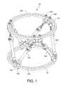
- FIG. 1is perspective view of a preferred embodiment of an orthopedic external fixator of the present disclosure.
- FIG. 2is a perspective view of another embodiment of an orthopedic external fixator of the present disclosure.
- FIG. 3Ais an isometric view of one of the single-hinged struts shown in FIG. 2 with one of the threaded rods removed from the locking universal joint hinge.
- FIG. 3Bis a plan view of the single-hinged strut of FIG. 3A .
- FIG. 3Cis a longitudinal section view of the single-hinged strut of FIG. 3B the section being taken through the line A-A in FIG. 3B .
- FIG. 4Ais an isometric view of a universal joint shown in FIG. 3A from a different angle.
- FIG. 4Cis a cross-sectional view of the universal joint of FIG. 4A wherein the section is taken through the plane A-A shown in FIG. 4B .
- FIG. 4Dis a cross-sectional view of the universal joint of FIG. 4A wherein the section is taken through the plane B-B shown in FIG. 4B .
- FIG. 4Bis a plan view of the universal joint of FIG. 4A looking down into the X-axis.
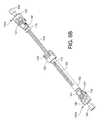
- FIG. 5is a plan view of a preferred embodiment of the adjustable strut of the external fixator of FIGS. 1 and 2 in its retracted configuration.
- FIG. 6Ais an isometric view of the adjustable strut of FIG. 5 in its retracted configuration.
- FIG. 6Bis an isometric view of the adjustable strut of FIG. 5 in its extended configuration.
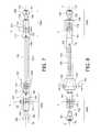
- FIGS. 7 and 8are additional plan views of the adjustable strut of FIG. 5 .
- FIG. 9Ais a longitudinal cross-sectional view of one embodiment of the adjustable strut of the present disclosure with the adjustment knob in the released position.
- FIG. 9Bis a transverse cross-sectional view through the adjustment knob shown in FIG. 9A in the released position.
- FIG. 9Cis a longitudinal cross-sectional view of the adjustable strut shown in FIG. 9A with the adjustment knob in the engaged position.
- FIG. 9Dis a transverse cross-sectional view through the adjustment knob shown in FIG. 9C in the engaged position.
- FIG. 10Ais a longitudinal cross-sectional view of another embodiment of the adjustable strut of the present disclosure with the adjustment knob in the engaged position.
- FIG. 10Bis a transverse cross-sectional view through the adjustment knob shown in FIG. 10A in the engaged position.
- FIG. 10Cis a longitudinal cross-sectional view of the adjustable strut shown in FIG. 10A with the adjustment knob in the released position.
- FIG. 10Dis a transverse cross-sectional view through the adjustment knob shown in FIG. 10C in the released position.
- FIG. 11Ais an isometric view of a ball-joint embodiment of the universal-hinged connector of the adjustable strut of the present disclosure.
- FIG. 11Bis a longitudinal cross-sectional view of the ball-joint embodiment of FIG. 11A .
- FIGS. 11C and 11Dillustrate another example of a ball joint in accordance with some embodiments.
- the orthopedic external fixator 20generally includes a pair of base members 21 , 22 that have ring-like structures that are connected by a plurality of telescopically adjustable struts 100 .
- Each of the ring-like base members 21 , 22can be a fully encircling ring as shown or a partial ring, such as a generally U-shaped foot ring.
- the two base members 21 , 22are connected by six telescopically adjustable struts 100 .
- the telescopically adjustable struts 100enable the orthopedic surgeon to configure and adjust the orientation of the two base members 21 , 22 relative to each other by adjusting the lengths of each strut 100 .
- Such feature of the external fixator 20is useful for treating a variety of fractures, nonunions, deformities and malunions of skeletal bone fragments.
- FIG. 2illustrates an example of such orthopedic external fixator 20 A, in which two ring-like base members 21 , 22 are connected by one telescopically adjustable strut 100 and two single-hinged struts 200 .
- the single-hinged struts 200include two threaded rods 212 , 214 joined by a locking universal-joint hinge 240 .
- the axes of the locking universal-joint hinges 240are configured to lock the universal-joint hinges 240 at a desired angle.
- the two threaded rods 212 , 214connect to the universal-joint hinge 240 by threading into the universal-joint hinge 240 from opposite ends. As shown in FIG.
- the universal-joint hinges 240can be configured to receive a wire 202 therethrough so that in the assembled arrangement 20 A, the wire 202 can be extended through the universal-joint hinges 240 of two oppositely positioned single-hinged struts 200 for aligning the single-hinged struts 200 .
- FIG. 3Ashows the locking universal-joint hinge 240 with one of the two threaded rods 212 threaded into the universal-joint hinge 240 while the other threaded rod 214 has been removed for illustration purposes.
- the isometric views of the universal-joint hinge 240 in FIGS. 3A and 4Ashow two pivot axes X and Y associated with the universal-joint hinge 240 .
- the locking universal-joint hinge 240comprises two clevis connectors, an X-axis clevis 241 and a Y-axis clevis 242 that are pivotally connected by a cross-shaft member 250 .
- An X-axis clevis pin 231pivotally connects the X-axis clevis 241 to the cross shaft member 250 and allows the X-axis clevis 241 to pivot about the first pivot axis X.
- a Y-axis clevis pin 232pivotally connects the Y-axis clevis 242 to the cross shaft member 250 and allows the Y-axis clevis 242 to pivot about the second pivot axis Y.
- the cross-shaft member 250is configured to have the X and Y pivot axes intersect orthogonally. Therefore, while the X-axis clevis pin 231 is a single piece pin extending through the cross-shaft member 250 as shown in the cross-sectional views of FIGS. 3C and 4C , the Y-axis clevis pin 232 comprises two pieces pivotally connecting the Y-axis clevis 242 to the cross-shaft member 250 as shown in FIG. 4D . To allow for the wire 202 described above, the X-axis clevis pin 231 is provided with a cannula 231 c extending longitudinally therethrough as shown in FIGS. 3C and 4C .
- Each of the X-axis clevis 241 and the Y-axis clevis 242are provided with threaded holes 241 h , 242 h , respectively, for receiving the threaded rods 212 , 214 .
- the threaded holes 241 h , 242 hare oriented so that their threading axes are orthogonal to their respective X and Y pivot axes.
- the longitudinal axis of the threaded hole 241 his orthogonal to the pivot axis X and the longitudinal axis of the threaded hole 242 h is orthogonal to the pivot axis Y.
- the X-axis clevis pin 231is structured like a bolt and has a head and a shaft.
- the head of the X-axis clevis pin 231will be referred to herein as the proximal end of the pin and the opposite end of the shaft will be referred to as the distal end of the pin.
- the X-axis clevis 241has a generally U-shaped structure and has two arms 241 a , 241 b with the cross-shaft member 250 positioned in between the two arms.
- the shaft of the X-axis clevis pin 231extends from the first arm 241 a , through the cross shaft member 250 , to the second arm 241 b through holes provided in the arms 241 a , 241 b .
- the distal end of the X-axis clevis pin 231threadably engages the arm 241 a and is held in place.
- the distal end of the pincan be mechanically secured.
- a snap ring 235is used to keep the X-axis clevis pin 231 from being removed.
- a cotter pin or other suitable mechanical meanscan be used in place of the snap ring 235 .
- the universal joint hinge 240is configured for locking the X and Y pivoting axes of the X-axis clevis 241 and the Y-axis clevis 242 .
- the X axiscan be locked by tightening the X-axis clevis pin 231 .
- the shaft of the X-axis clevis pin 231has a larger diameter than the rest of the shaft and a shoulder 231 a circumscribing the shaft of the pin is defined where the diameter changes.
- the shoulder 231 a of the X-axis clevis pin 231has a larger diameter than the opening in the cross-shaft member 250 through which the X-axis clevis pin 231 extends.
- the shoulder 231 aurges the cross-shaft member 250 against the X-axis hinge arm 241 a (see FIGS. 4C and 4D ).
- the inner surface 245 of the X-axis clevis arm 241 a that contacts the cross-shaft member 250 and the corresponding contacting surface 255 of the cross-shaft member 250are configured to frictionally or mechanically engage each other and lock the X-axis clevis 241 and the cross-shaft member 250 together.
- This lockingprevents the X-axis clevis 241 from pivoting about the X axis relative to the cross-shaft member 250 and the Y-axis clevis 242 .
- the inner surface 245 and the contacting surface 255 of the cross-shaft member 250can be roughened surfaces, e.g., diamond teethed, knurled, etc. to generate the frictional or mechanical interference and aid in the locking.
- This locking configuration for the X-axis clevis 241 and the X-axis clevis pin 231allows the X-axis clevis 241 to be locked at a variety of pivot angles with respect to the Y-axis clevis 242 .
- the Y axiscan be locked by threading the threaded rod 214 into the Y-axis clevis 242 until the threaded rod 214 contacts the cross-shaft member 250 and tightening the threaded rod 214 against the cross-shaft member 250 .
- a sufficient frictional interference between the threaded rod 214 and the surface of the cross-shaft member 250can be created to lock and prevent the Y-axis clevis 242 from pivoting about the Y axis.
- the cross-shaft member 250has a substantially spherical shape whose center is located at the point of intersection of the pivot axis X and the pivot axis Y. The spherical shape allows the Y-axis clevis 242 to pivot about the pivot axis Y even with the threaded rod 214 extending through the clevis up to the cross-shaft member 250 but not quite in locking position.
- the respective contacting surfacescan be configured and adapted to increase the frictional force.
- the outer surface of the cross-shaft member 250can be provided with a desired surface roughness.
- the corresponding surface at the end of the threaded rod 214 that contacts the cross-shaft member 250can also be configured appropriately to enhance the frictional interference between the two contacting surfaces.
- the contacting surface of the threaded rod 214also can be provided with a desired surface roughness.
- the contacting surface of the threaded rod 214also can be provided with a concave contour matching the surface contour of the cross-shaft member 250 to increase the contact area between the threaded rod 214 and the cross-shaft member 250 .
- the cross-shaft member 250is configured to enable locking of the Y-axis clevis 242 only at a single predefined angle with respect to the X axis.
- a band of flat surface 252is provided on the surface of the cross-shaft member 250 at least partially circumscribing the cross-shaft member 250 on the side facing the threaded rod 214 advancing through the Y-axis clevis.
- the band of flat surface 252is oriented so that it extends parallel to the Y axis and orthogonal to the X axis.
- the band of flat surface 252is positioned at the equatorial position on the cross-shaft member 250 if the X axis was viewed as going through the North and South poles of a globe represented by the spherical cross-shaft member 250 .
- the equatorially positioned band of flat surface 252allows the Y-axis clevis 242 to be locked only at a position orthogonal to the X-axis as shown.
- the threaded rod 214 threaded into the internally threaded hole 242 h of the Y-axis clevis 242would be oriented orthogonal to the X-axis.
- the band of flat surface 252can be oriented at an angle that is not orthogonal with respect to the X axis in order to allow the Y-axis clevis 242 to lock only at that particular angle.
- the adjustable strut 100has a generally elongated structure comprising two ends. Provided at each end is a universal joint connector 140 A, 140 B for connecting the adjustable strut 100 to orthopedic external fixator base members 21 , 22 .
- the adjustable strut 100comprises an elongated shaft 102 with a hollow axial center 102 c (shown in FIG. 7 ) and a lead screw 110 , one end of which extends into the hollow axial center 102 c.
- the universal-joint connector 140 Aconnects the elongated shaft 102 end of the adjustable strut 100 to a base member 21 , 22 of the external fixator 20 while allowing the connection to be made at a variety of angles and directions.
- a second universal-joint connector 140 Bis provided at opposite ends of the strut 100 .
- the universal-joint connector 140 Bconnects the lead screw 110 end of the adjustable strut 100 to another base member 21 , 22 of the external fixator 20 while allowing that connection to be made at a variety of angles and directions.
- the term “universal-joint connector” as used hereinrefers to a connector connecting two parts that is configured and adapted to bend or flex in a variety of angles.
- the universal-joint connectors 140 A, 140 Bcan be any type of jointed or hinged connectors that provide robust articulation of the connection between the adjustable strut 100 and the base members 21 , 22 of the external fixator 20 .
- the robust articulationallows a variety of angular configurations for the two ends of the adjustable strut 100 attached to the base members 21 , 22 of the external fixator 20 .
- FIGS. 7-9Athe structures of the universal-joint connectors 140 A and 140 B will be described in more detail.
- the universal-joint connectors 140 A, 140 Bhave similar structure as the universal-joint hinges 240 shown in FIGS. 4A-4D .
- FIGS. 7 and 8show the two pivot axes X and Y associated with the structure of the universal-joint connectors 140 A, 140 B.
- each of the universal-joint connectors 140 A, 140 Bcomprises two clevis connectors, an X-axis clevis 141 and a Y-axis clevis 142 that are pivotally connected by a cross-shaft member 150 .
- the arrangement and interacting movement of the X-axis clevis 141 and the Y-axis clevis 142is same as that of the corresponding devises in the universal-joint hinge 240 .
- the X-axis clevis 141connects the universal-joint connectors 140 A, 140 B to the shaft 102 or the lead screw 110 .
- the Y-axis clevis 142connects the universal-joint connectors 140 A, 140 B to the base members 21 , 22 by Z-axis screws 160 .
- the Z-axis screw 160is inserted through one of the mounting holes 21 h , 22 h in the base members 21 , 22 and threaded into the Y-axis clevis 142 .
- An X-axis pin 131 and the Y-axis pin 132correspond to the X-axis pin 231 and the Y-axis pin 232 , respectively, of the universal joint hinge 240 .
- the X-axis clevis 141is configured to be attached to either the shaft 102 or the lead screw 110 at its base portion.
- a variety of attachment methods and configurationscan be used to attach the X-axis clevis 141 to the shaft 102 or the lead screw 110 .
- the attachment between the X-axis clevis 141 and the shaft 102 and/or the lead screw 110are enabled by a cross pin 180 . This is better shown in detail in the longitudinal cross-sectional view of the adjustable strut 100 shown in FIG. 10A .
- the X-axis clevis 141 and the cross-shaft member 150are configured to enable locking of the X-axis to prevent the X-axis hinge 141 from pivoting about the pivot axis X. Except for the fact that the X-axis clevis pin 131 is not cannulated, the X-axis clevis pin 131 has the same structure as the X-axis clevis pin 231 of the universal joint hinge 240 .
- the X-axis clevis 141has a generally U-shaped structure and has two arms 141 a , 141 b with the cross-shaft member 150 positioned therebetween.
- the shaft of the X-axis clevis pin 131extends from the first arm 141 a , through the cross-shaft member 150 , and to the second arm 141 b through the openings provided in the arms 141 a , 141 b .
- the distal end of the X-axis clevis pin 131threadably engages the arm 141 a and is held in place.
- the distal end of the pincan be mechanically secured.
- a snap ring 135is used to keep the X-axis clevis pin 131 from being removed.
- a cotter pincan be used in place of the snap ring 135 .
- the universal joint connectors 140 A, 140 Bare configured for locking the X and Y pivoting axes. This locking is accomplished in a similar manner to the universal joint hinge 240 by the operation of the X-axis clevis pin 131 .
- the X-axis clevis pin 131is configured to have a shoulder, like the shoulder 231 a of the X-axis clevis pin 231 , that urges the cross-shaft member 150 toward the X-axis clevis arm 141 a (in the upward direction in FIG. 9A ).
- the surfaces of the X-axis clevis arm 141 a and the cross-shaft member 150 that contact each otherare configured like the corresponding roughened contacting surfaces 245 and 255 of the universal joint hinge 240 to frictionally engage each other for locking the X-axis clevis 141 and the cross-shaft member 150 together.
- the Y-axis clevis 142can be configured to be locked for stopping the pivoting movement of the Y-axis clevis 142 about the pivot axis Y.
- the Z-axis screw 160has an internally threaded longitudinal bore 167 and a Y-axis locking screw 170 is threaded into the longitudinal bore 167 . As shown in FIG. 9A , the distal end 175 of the locking screw's stem extends out of the distal end of the Z-axis screw 160 . As shown in FIG.
- the terminal surface of the distal end 175 of the Y-axis locking screw 170 that contacts the cross-shaft member 150has a concave contour so that the contacting surface area is a circle rather than a single point, thus, optimizing the frictional interference between the distal end 175 of the Y-axis locking screw 170 and the cross-shaft member 150 .
- the base portion of the Y-axis clevis 142is configured to be attached to a base member 21 , 22 of the external fixator 20 by a Z-axis screw 160 .
- the Z-axis screw 160is threaded into the base portion of the Y-axis clevis 142 and has a cylindrical mid-section 165 that is smaller in diameter than the head portion 161 of the Z-axis screw 160 .
- the mid-section 165defines a gap between the head portion 161 of the Z-axis screw 160 and the Y-axis clevis 142 which accommodates the thickness of the base member 21 , 22 of the external fixator 20 .
- the Z-axis screw 160is inserted through one of the mounting holes 21 h , 22 h in the base members 21 , 22 and threaded into the base portion of the Y-axis clevis 142 to secure the strut 100 to the base member 21 , 22 . This is better illustrated in FIG. 1 .
- the gap between the head portion 161 of the Z-axis screw 160 and the Y-axis clevis 142is appropriately matched to the thickness of the base member 21 , 22 such that when the strut 100 is attached to the base member 21 , 22 and the Z-axis screw 160 is tightened, the base member 21 , 22 gets locked between the Y-axis clevis 142 and the head portion 161 of the Z-axis screw 160 and the strut 100 is prevented from rotating about the Z-axis.
- FIGS. 11A-11Billustrate an example of an alternate type of connectors.
- FIGS. 11A-11Bshow a ball-joint 300 example.
- the ball-joint 300comprises a ball 302 that is captured between two ball-joint housing halves 312 , 314 .
- the first ball-joint housing half 312threads onto the second ball-joint housing half 314 .
- the internal structures of the two ball-joint housing halves 312 , 314are configured to form a spherical volume within which the ball 302 sits as shown in the cross-sectional view of FIG. 11B .
- the ball 302has a stem 303 that extends out of an axially oriented opening in the first ball-joint housing half 312 .
- the stem 303has a terminal end 304 that is configured and adapted to receive and connect to either the lead screw 110 or the shaft 102 of the adjustable strut 100 .
- the terminal end 304 of the stem 303is provided with an axially positioned hollow opening 305 for receiving either the lead screw 110 or the shaft 102 .
- a cross pin 180can be utilized to keep the lead screw 110 or the shaft 102 attached to the terminal end 304 of the stem 303 .
- the connecting piece 320Threadably attached to the second ball-joint housing half 314 is a connecting piece 320 for attaching the ball-joint 300 to one of the base members 21 , 22 of the external fixator 20 .
- the connecting piece 320has two threaded stem portions 322 and 324 extending in opposite directions. The first end 322 is threaded into the second ball-joint housing half 314 and the second end 324 is configured for attaching to one of the base members 21 , 22 .
- the connecting piece 320has a middle portion 325 that is configured to accommodate turning by hand or a tool such as a wrench. In the illustrated example, the middle portion 325 has a six-sided nut like structure optimized for turning with an open-ended wrench.
- the second end 324is threaded to receive a locking nut 330 for holding the base member 21 , 22 between the middle portion 325 and the locking nut 330 .
- the second end 324is inserted into one of the mounting holes 21 h , 22 h provided on the base members 21 , 22 and held in place by threading the locking nut 330 on to the second end 324 .
- the ball 302swivels between the two ball-joint housing halves 312 , 314 to allow adjustment of the attachment angle between the strut 100 and the base member 21 , 22 . Then the attachment angle can be fixed by locking the ball-joint 300 .
- the lockingis achieved by tightening the two ball-joint housing halves 312 , 314 together and preventing the ball 302 from swiveling.
- FIGS. 11C and 11Dshow another ball-joint 300 a according to another embodiment for the universal-hinged connectors 140 A, 140 B.
- the ball-joint 300 acomprises a ball 302 that is captured between two ball-joint housing halves 312 and 350 .
- the first ball-joint housing half 312threads onto the second ball-joint housing half 350 .
- the internal structures of the two ball-joint housing halves 312 , 350are configured to form a spherical volume within which the ball 302 sits as shown in the cross-sectional view of FIG. 11C .
- the ball 302has a structure similar to the ball 302 in the embodiment shown in FIG. 11B and is configured and adapted to receive and connect to either the lead screw 110 or the shaft 102 of the adjustable strut 100 .
- the second ball-joint housing half 350is comprises a stem portion 352 for attaching the ball-joint 300 a to one of the base members 21 , 22 of the external fixator 20 .
- the stem portions 352has an externally threaded distal end 354 that extends through one of the mounting holes 21 h , 22 h provided on the base members 21 , 22 .
- the second ball-joint housing half 350is secured in place by a nut 330 a that threads onto the distal end 354 .
- locking of the ball 302is achieved by the use of a locking pin 340 that is received through the stem 352 of the second ball-joint housing half 350 from the distal end 354 of the stem 352 .
- the stem 352is cannulated and the locking pin 340 has a shaft 342 that is received through the cannnulated stem 352 .
- the shaft 342 of the locking pin 340extends through the cannulated stem 352 and contacts the ball 302 by its distal end 345 .
- the head of the locking pin 340is provided with an annular recess 343 near the base of the shaft 342 for threadably engaging the externally threaded distal end 354 of the stem portion 352 .
- the outer wall 344 of the annular recess 343is threaded for threadably engaging the threaded distal end 354 of the stem portion 352 .
- the distal tip 345 of the shaft 342can be configured to have a concave surface to optimize the surface area of the contact with the ball 302 and thus optimize the frictional interference generated.
- the nut 330 acan be countersunk for accommodating the head of the locking pin 340 as shown in FIG. 11C to minimize the protrusion of the structures from the base members 21 , 22 .
- an adjustment knob 120that is configured to threadably engage the lead screw 110 for telescopically adjusting the strut 100 .
- the adjustment knob 120is rotatably attached to the elongated shaft 102 to be axially rotated.
- the adjustment knob 120can be rotatably attached to the end of the shaft 102 by an appropriate bearing mechanism 220 .
- the bearing mechanism 220can be secured to the adjustment knob 120 by an appropriate means known in the art. For example, the two pieces can be held together by press-fitting, welding, threading, a locking pin or adhesively attaching.
- the end of the shaft 102can be provided with a flange 102 a to keep the adjustment knob 120 assembly attached to the shaft 102 .
- the adjustment knob 120is provided with an axially-oriented opening 120 c (shown in FIG. 7 ) through which the lead screw 110 extends into the hollow axial center 102 c of the shaft 102 .
- the adjustment knob 120is provided with a release button 122 that is movable between an engaged position and a released position.
- the release button 122is configured to threadably engage the external threads of the lead screw 110 when in the engaged position and disengage from the external threads of the lead screw 110 when in the released position.
- FIGS. 5 and 6Ashow the strut 100 in fully retracted configuration and FIG. 6B shows the strut 100 in fully extended configuration.
- the adjustment knob 120is marked with directional markings 120 m identifying the directions of rotation that will extend or retract the strut.
- the adjustment knob 120 shown in FIG. 5is marked with an arrow and a “+” character denoting that turning the adjustment knob 120 in the direction of the arrow will extend the strut 100 .
- the lead screw 110 and the shaft 102are configured to prevent relative axial rotation of the lead screw 110 and the shaft 102 .
- the shaft 102is provided with a slot 103 extending along a side of the shaft 102 in the axial direction and a projection 112 provided on the lead screw 110 extends into the slot 103 so that the mechanical interference between the projection 112 and the slot 103 prevents axial rotation of the lead screw 110 relative to the shaft 102 .
- a locking nut 115Threaded onto the lead screw 110 between the adjustment knob 120 and the universal joint connector 140 B is a locking nut 115 for locking the adjustment knob 120 and preventing the adjustment knob 120 from turning.
- the locking nut 115is used to fix the length of the strut 100 after being adjusted to a desired length. After the strut 100 is adjusted to a desired length by the use of the adjustment knob 120 , the locking nut 115 is tightened against the adjustment knob 120 thus preventing the adjustment knob 120 from turning and locking the strut 100 at that particular length.
- FIGS. 9A and 9Bshow the release button 122 in the released position and FIGS. 9C and 9D show the release button 122 in the engaged position.
- the adjustment knob 120has a recessed cavity 121 within which the release button 122 is situated.
- the cavity 121is open at one end so that the release button 122 is exposed to allow a user to press it down into the cavity 121 when necessary.
- the release button 122has an elongated opening 123 that is substantially in alignment with the axially-oriented opening 120 c of the adjustment knob 120 so that the lead screw 110 extends therethrough.
- the elongated or oblong opening 123is appropriately sized and has an internally threaded portion 124 on one side that engages the external threads of the lead screw 110 when the button 122 is in its engaged position.
- the release button 122is configured and adapted to be normally maintained in the released position shown in FIGS. 9A and 9B as the default position so that the length of the adjustable strut 100 can be quickly adjusted close or roughly to a desired length.
- the release button 122can then be set to its engaged position enabling fine adjustment of the strut's length by rotating the adjustment knob 120 .
- a ball detent mechanism 122 bprovided between the release button 122 and the adjustment knob 120 maintains the release button 122 in the released position shown in FIGS. 9A and 9B as the default position.
- the ball detent 122 bsits within a first recess 122 a provided in the release button 122 and is urged outward by a coil spring 122 c .
- a second recess 120 ais provided in the side wall of the recessed cavity 121 that faces the ball detent 122 b .
- the second recess 120 a and the ball detent 122 bare positioned so that the ball detent 122 b and the second recess 120 a comes into alignment when the release button 122 is in its released position.
- the ball detent 122 bis partially urged into the second recess 120 a by the coil spring 122 c .
- the diameter of the second recess 120 ais smaller than the diameter of the ball detent 122 b so that the ball detent 122 b only partially protrudes into the second recess rather than completely falling into the second recess 120 a.
- the release button 122can be moved from the default released position shown in FIG. 9B to the engaged position shown in FIGS. 9C and 9D by threading the button-engaging screw 129 further into the adjustment knob 120 .
- the advancing button-engaging screw 129pushes the release button 122 until the internally threaded portion 124 of the oblong opening 123 engages the threads on the lead screw 110 .
- a washer or a ring 127 attached to the distal end of the button-engaging screw 129is provided for retaining the button-engaging screw 129 in place so that the screw 129 does not disengage from the adjustment knob 120 unintentionally.
- FIGS. 10A-10Dshow the configuration of the release button 122 according to another embodiment.
- the release button 122 in this embodimentis configured to be normally in the engaged position.
- the release button 122is spring-biased by an elastically compressible member 128 that is provided at the bottom of the cavity 121 .
- the compressible member 128can be a coil spring or a piece of an elastomeric material that can keep the release button 122 urged against the lead screw 110 as illustrated in FIGS. 10A and 10B .
- the release button 122can be used to quickly release the lead screw 110 and slide it in or out of the shaft 102 to adjust the length of the telescopically adjustable strut 100 .
- a button-locking screw 129also can be provided at the bottom of the cavity 121 .
- the button-locking screw 129is threaded into the adjustment knob 120 so that by threading the screw 129 further into the cavity 121 until the screw 129 contacts the release button 122 , the release button 122 can be locked in its engaged position.
- an appropriate recessis provided in the button-locking screw 129 for holding the spring-biasing member 128 in place.
- a washer 127can be places at the bottom of the cavity 121 to keep the button-locking screw 129 in the assembly.
- the threads on the lead screw 110 and the release button 122 of the adjustment knob 120are pitched such that a predetermined number of revolutions of the adjustment knob 120 about the axis of the shaft results in the lead screw 110 being axially translated by a desired incremental distance.
- the threadscan be pitched so that a known amount of revolution (e.g. one or more revolutions or a fraction of a revolution) of the adjustment knob 120 causes the lead screw 110 to axially translate a predetermined distance relative to the shaft 102 .
- the predetermined distancecan be a fraction of a millimeter or more than a millimeter.
- the shaft 102can further comprise graduated marks 105 provided along the slot 103 , whereby the length of the strut is indicated by the location of the projection 112 relative to the graduated marks 115 , the length of the adjustable strut 100 being defined by a predetermined end points on the strut.
- the predetermined end points defining the length of the strut 100can be the ends 142 e of the two Y-axis clevis connectors 142 and the distance between the two ends 142 e are indicated by the projection 112 and the graduated marks 105 .
- the length of the strutcan be defined as the distance between the two pivot axes X of the universal-hinged connectors 140 A, 140 B and the graduated marks 105 are marked accordingly to indicate that distance as indicated by the projection 112 .
- two base members 21 , 22 of an external fixatorcan be set to a particular configuration by adjusting the lengths of the adjustable struts 100 and the angles of attachment at either ends of the struts 100 via the universal-hinged connectors 140 A, 140 B.
Landscapes
- Health & Medical Sciences (AREA)
- Orthopedic Medicine & Surgery (AREA)
- Life Sciences & Earth Sciences (AREA)
- Surgery (AREA)
- Biomedical Technology (AREA)
- Engineering & Computer Science (AREA)
- Nuclear Medicine, Radiotherapy & Molecular Imaging (AREA)
- Heart & Thoracic Surgery (AREA)
- Medical Informatics (AREA)
- Molecular Biology (AREA)
- Animal Behavior & Ethology (AREA)
- General Health & Medical Sciences (AREA)
- Public Health (AREA)
- Veterinary Medicine (AREA)
- Surgical Instruments (AREA)
Abstract
Description
Claims (31)
Priority Applications (8)
| Application Number | Priority Date | Filing Date | Title |
|---|---|---|---|
| US12/711,591US8257353B2 (en) | 2010-02-24 | 2010-02-24 | Orthopedic external fixation device |
| EP20110707035EP2538859B1 (en) | 2010-02-24 | 2011-02-24 | Orthopedic external fixation device |
| EP14173211.5AEP2789302B1 (en) | 2010-02-24 | 2011-02-24 | Orthopedic external fixation device |
| CA2790490ACA2790490C (en) | 2010-02-24 | 2011-02-24 | Orthopedic external fixation device |
| PCT/US2011/026051WO2011106507A1 (en) | 2010-02-24 | 2011-02-24 | Orthopedic external fixation device |
| US13/568,302US8454604B2 (en) | 2010-02-24 | 2012-08-07 | Orthopedic external fixation device |
| US13/896,060US9066756B2 (en) | 2010-02-24 | 2013-05-16 | Orthopedic external fixation device |
| US14/705,345US9717529B2 (en) | 2010-02-24 | 2015-05-06 | Orthopedic external fixation device |
Applications Claiming Priority (1)
| Application Number | Priority Date | Filing Date | Title |
|---|---|---|---|
| US12/711,591US8257353B2 (en) | 2010-02-24 | 2010-02-24 | Orthopedic external fixation device |
Related Child Applications (1)
| Application Number | Title | Priority Date | Filing Date |
|---|---|---|---|
| US13/568,302ContinuationUS8454604B2 (en) | 2010-02-24 | 2012-08-07 | Orthopedic external fixation device |
Publications (2)
| Publication Number | Publication Date |
|---|---|
| US20110208187A1 US20110208187A1 (en) | 2011-08-25 |
| US8257353B2true US8257353B2 (en) | 2012-09-04 |
Family
ID=43855940
Family Applications (4)
| Application Number | Title | Priority Date | Filing Date |
|---|---|---|---|
| US12/711,591Active2030-08-07US8257353B2 (en) | 2010-02-24 | 2010-02-24 | Orthopedic external fixation device |
| US13/568,302ActiveUS8454604B2 (en) | 2010-02-24 | 2012-08-07 | Orthopedic external fixation device |
| US13/896,060Active2030-05-07US9066756B2 (en) | 2010-02-24 | 2013-05-16 | Orthopedic external fixation device |
| US14/705,345ActiveUS9717529B2 (en) | 2010-02-24 | 2015-05-06 | Orthopedic external fixation device |
Family Applications After (3)
| Application Number | Title | Priority Date | Filing Date |
|---|---|---|---|
| US13/568,302ActiveUS8454604B2 (en) | 2010-02-24 | 2012-08-07 | Orthopedic external fixation device |
| US13/896,060Active2030-05-07US9066756B2 (en) | 2010-02-24 | 2013-05-16 | Orthopedic external fixation device |
| US14/705,345ActiveUS9717529B2 (en) | 2010-02-24 | 2015-05-06 | Orthopedic external fixation device |
Country Status (4)
| Country | Link |
|---|---|
| US (4) | US8257353B2 (en) |
| EP (2) | EP2789302B1 (en) |
| CA (1) | CA2790490C (en) |
| WO (1) | WO2011106507A1 (en) |
Cited By (38)
| Publication number | Priority date | Publication date | Assignee | Title |
|---|---|---|---|---|
| US20090264883A1 (en)* | 2008-04-18 | 2009-10-22 | Stryker Trauma Sa | Radiolucent orthopedic fixation plate |
| US20100305568A1 (en)* | 2008-02-05 | 2010-12-02 | Texas Scottish Rite Hospital For Children | External fixator ring |
| US20110004199A1 (en)* | 2008-02-18 | 2011-01-06 | Texas Scottish Rite Hospital For Children | Tool and method for external fixation strut adjustment |
| US20120078251A1 (en)* | 2010-09-23 | 2012-03-29 | Mgv Enterprises, Inc. | External Fixator Linkage |
| US20120143190A1 (en)* | 2010-11-30 | 2012-06-07 | OrthoLan LLC | Orthopedic fixation systems and methods |
| US8574232B1 (en) | 2012-11-13 | 2013-11-05 | Texas Scottish Hospital for Children | External fixation connection rod for rapid and gradual adjustment |
| US20140079183A1 (en)* | 2012-09-18 | 2014-03-20 | Jan Rimbach | Apparatus for Examining Test Bodies |
| US8834467B2 (en) | 2010-08-11 | 2014-09-16 | Stryker Trauma Sa | External fixator system |
| US20140278325A1 (en)* | 2011-06-23 | 2014-09-18 | Stryker Trauma Gmbh | Methods and systems for adjusting an external fixation frame |
| US8864763B2 (en) | 2013-03-13 | 2014-10-21 | DePuy Synthes Products, LLC | External bone fixation device |
| US8945128B2 (en) | 2010-08-11 | 2015-02-03 | Stryker Trauma Sa | External fixator system |
| US8951252B2 (en) | 2008-04-18 | 2015-02-10 | Stryker Trauma Sa | External fixation system |
| US9039706B2 (en) | 2013-03-13 | 2015-05-26 | DePuy Synthes Products, Inc. | External bone fixation device |
| US9044271B2 (en) | 2009-03-10 | 2015-06-02 | Stryker Trauma Sa | External fixation system |
| US9066756B2 (en) | 2010-02-24 | 2015-06-30 | Wright Medical Technology, Inc. | Orthopedic external fixation device |
| US9078700B2 (en) | 2008-02-12 | 2015-07-14 | Texas Scottish Rite Hospital For Children | Fast adjust external fixation connection rod |
| US9101398B2 (en) | 2012-08-23 | 2015-08-11 | Stryker Trauma Sa | Bone transport external fixation frame |
| US9155559B2 (en) | 2008-02-08 | 2015-10-13 | Texas Scottish Rite Hospital For Children | External fixator strut |
| US9204937B2 (en) | 2013-02-19 | 2015-12-08 | Stryker Trauma Gmbh | Software for use with deformity correction |
| US9443302B2 (en) | 2010-08-20 | 2016-09-13 | Amei Technologies, Inc. | Method and system for roentgenography-based modeling |
| US9524581B2 (en) | 2012-02-03 | 2016-12-20 | Stryker European Holdings I, Llc | Orthopedic treatment device co-display systems and methods |
| US9642649B2 (en) | 2010-05-19 | 2017-05-09 | DePuy Synthes Products, Inc. | Orthopedic fixation with imagery analysis |
| US9675382B2 (en) | 2013-03-13 | 2017-06-13 | DePuy Synthes Products, Inc. | External bone fixation device |
| US9827011B2 (en)* | 2013-03-15 | 2017-11-28 | Biomet Manufacturing, Llc | Polyaxial pivot housing for external fixation system |
| US9895167B2 (en) | 2016-04-20 | 2018-02-20 | Stryker European Holdings I, Llc | Ring hole planning for external fixation frames |
| US9936975B2 (en) | 2014-09-09 | 2018-04-10 | Integra Lifesciences Corporation | External fixation system |
| US9962188B2 (en) | 2013-10-29 | 2018-05-08 | Cardinal Health 247. Inc. | External fixation system and methods of use |
| US10010350B2 (en) | 2016-06-14 | 2018-07-03 | Stryker European Holdings I, Llc | Gear mechanisms for fixation frame struts |
| US20180228515A1 (en)* | 2016-02-03 | 2018-08-16 | Texas Scottish Rite Hospital For Children | Dynamization device for orthopedic fixation device |
| US10082384B1 (en) | 2015-09-10 | 2018-09-25 | Stryker European Holdings I, Llc | Systems and methods for detecting fixation frame parameters |
| US10154884B2 (en) | 2016-06-02 | 2018-12-18 | Stryker European Holdings I, Llc | Software for use with deformity correction |
| US10835318B2 (en) | 2016-08-25 | 2020-11-17 | DePuy Synthes Products, Inc. | Orthopedic fixation control and manipulation |
| US10874433B2 (en) | 2017-01-30 | 2020-12-29 | Stryker European Holdings I, Llc | Strut attachments for external fixation frame |
| US11141196B2 (en) | 2010-08-11 | 2021-10-12 | Stryker European Operations Holdings Llc | External fixator system |
| US11304757B2 (en) | 2019-03-28 | 2022-04-19 | Synthes Gmbh | Orthopedic fixation control and visualization |
| US11334997B2 (en) | 2020-04-03 | 2022-05-17 | Synthes Gmbh | Hinge detection for orthopedic fixation |
| US11439436B2 (en) | 2019-03-18 | 2022-09-13 | Synthes Gmbh | Orthopedic fixation strut swapping |
| US12310627B1 (en)* | 2019-03-15 | 2025-05-27 | Christopher Condon | External fixation device |
Families Citing this family (40)
| Publication number | Priority date | Publication date | Assignee | Title |
|---|---|---|---|---|
| WO2013126026A1 (en)* | 2012-02-24 | 2013-08-29 | Irşadi Istemi Alp Yücel | Annular bone fixation system with nine legs and apparatus |
| US9474552B2 (en)* | 2012-05-04 | 2016-10-25 | Biomet Manufacturing, Llc | Ratcheting strut |
| US9820776B2 (en) | 2012-05-04 | 2017-11-21 | Biomet Manufacturing, Llc | Ratcheting strut |
| US8906021B1 (en)* | 2012-08-20 | 2014-12-09 | Stryker Trauma Sa | Telescopic strut for an external fixator |
| WO2014055202A1 (en)* | 2012-09-06 | 2014-04-10 | Solana Surgical LLC | External fixator |
| US9289238B2 (en) | 2014-04-23 | 2016-03-22 | Texas Scottish Rite Hospital For Children | Dynamization module for external fixation strut |
| WO2015167581A1 (en)* | 2014-05-02 | 2015-11-05 | Wright Medical Technology, Inc. | Circular fixator system and method |
| WO2016149470A2 (en)* | 2015-03-17 | 2016-09-22 | Jeffery Cresina | External fixation system |
| JP6556247B2 (en)* | 2015-04-03 | 2019-08-07 | アカリー, イブラヒム デニズAKCALI, Ibrahim Deniz | Lambda type fixing device |
| KR101780225B1 (en) | 2016-01-26 | 2017-09-21 | 경북대학교 산학협력단 | An exterial fixator and a system of an exterial fixing |
| US9717530B1 (en)* | 2016-02-03 | 2017-08-01 | Texas Scottish Rite Hospital For Children | External fixation struts |
| AU2017217654B2 (en)* | 2016-02-09 | 2019-10-03 | Amdt Holdings, Inc. | External bone fixation systems |
| US10321166B2 (en)* | 2016-06-07 | 2019-06-11 | Orion Labs | Supplemental audio content for group communications |
| WO2017221243A1 (en)* | 2016-06-19 | 2017-12-28 | Orthospin Ltd. | User interface for strut device |
| GB2564103A (en)* | 2017-07-03 | 2019-01-09 | Univ Of Zagreb | An external load bearing distracting device for an articulating anatomical joint |
| CN107260274B (en)* | 2017-07-11 | 2019-07-12 | 荆门市第二人民医院 | An orthopedic reduction and fixation frame |
| IT201700086613A1 (en)* | 2017-07-27 | 2019-01-27 | Dial Medicali S R L | External hexapodalic fixator for orthopedic use with improved fastening actuators |
| WO2019046435A1 (en)* | 2017-08-31 | 2019-03-07 | J & A Medical Llc | External fixation alignment gauge |
| US10932820B2 (en)* | 2017-10-31 | 2021-03-02 | Life Spine, Inc. | Static strut and fixation constructs |
| CN107693096B (en)* | 2017-11-16 | 2019-08-23 | 河北博川医疗器械有限公司 | It is a kind of with the controlling type Bionics Bone external fixing rack that can lock gimbal suspension device |
| USD888947S1 (en) | 2018-03-14 | 2020-06-30 | J&A Medical LLC | External fixation alignment gauge |
| US11932171B2 (en)* | 2018-03-24 | 2024-03-19 | Greg Ferguson | Struts for vehicle mounted hoist |
| US10945763B2 (en) | 2018-05-31 | 2021-03-16 | Texas Scottish Rite Hospital For Children | Orthopedic spring hinge system and methods thereof |
| CN108742804B (en)* | 2018-06-05 | 2020-04-07 | 天津大学 | Parallel external fixing support for fracture reduction |
| US10743918B2 (en)* | 2018-06-27 | 2020-08-18 | Texas Scottish Rite Hospital For Children | External fixation connection rod with female attachment |
| US10751089B2 (en)* | 2018-08-21 | 2020-08-25 | New Standard Device, LLC | Orthopedic strut with lockable swivel hinges |
| BR112021003874A2 (en)* | 2018-08-29 | 2021-05-18 | Amdt Holdings, Inc. | adjustable support sets for external fastening systems |
| WO2020092049A1 (en) | 2018-10-30 | 2020-05-07 | Smith & Nephew, Inc. | External fixation strut |
| EP3946100B1 (en) | 2019-03-26 | 2023-10-11 | Smith & Nephew, Inc. | External fixation strut |
| US11596442B2 (en)* | 2019-06-21 | 2023-03-07 | Texas Scottish Right Hospital for Children | Dynamization tabs providing component interconnectivity for external fixation devices |
| WO2021011532A1 (en)* | 2019-07-15 | 2021-01-21 | Amdt Holdings, Inc. | Strut assemblies and external fixation systems |
| US12161946B2 (en) | 2019-11-19 | 2024-12-10 | Moog Inc. | Motion simulator fault tolerant load carrying pivot connection |
| EP4042957B1 (en)* | 2020-03-23 | 2023-11-01 | Orthofix S.r.l. | Improved external fixation strut |
| US11826077B2 (en)* | 2020-03-23 | 2023-11-28 | Texas Scottish Rite Hospital For Children | External fixation strut |
| ES2972373T3 (en)* | 2020-03-23 | 2024-06-12 | Orthofix Srl | Improved external fixation strut |
| US11457950B2 (en)* | 2020-04-27 | 2022-10-04 | DePuy Synthes Products, Inc. | Locking system and method |
| CN112244971B (en)* | 2020-11-11 | 2021-09-24 | 湖南旺旺医院有限公司 | Orthopedics reduction fixer |
| US11497527B1 (en) | 2021-09-09 | 2022-11-15 | Texas Scottish Rite Hospital For Children | Orthopedic spring hinge systems and methods |
| US11457965B1 (en) | 2021-11-12 | 2022-10-04 | University Of Utah Research Foundation | Rotational guided growth devices, systems, and methods |
| US12364510B2 (en)* | 2021-12-20 | 2025-07-22 | Stryker European Operations Limited | Quick release mechanism for strut |
Citations (20)
| Publication number | Priority date | Publication date | Assignee | Title |
|---|---|---|---|---|
| US3941123A (en) | 1975-05-20 | 1976-03-02 | Mstislav Vasilievich Volkov | Apparatus for joint movement restitution |
| US3985127A (en) | 1975-06-11 | 1976-10-12 | Mstislav Vasilievich Volkov | Apparatus for surgical treatment of the knee joint |
| US3993055A (en) | 1975-06-11 | 1976-11-23 | Mstislav Vasilievich Volkov | Apparatus for surgical treatment of bone fractures and diseases |
| US4100919A (en) | 1976-12-08 | 1978-07-18 | Tsentralny Nauchno-Issledovatelsky Institut Travmatologii I Ortopedii Imeni N.N. Priorova | Apparatus for surgical treatment of bones and joints |
| US4185623A (en) | 1978-07-18 | 1980-01-29 | Oganesian Oganes V | Apparatus for restoration of hip joint mobility |
| US4308863A (en)* | 1979-10-18 | 1982-01-05 | Ace Orthopedic Manufacturing, Inc. | External fixation device |
| US4312336A (en)* | 1978-11-10 | 1982-01-26 | Orthofix S.R.1. | External axial fixation unit |
| US4768524A (en) | 1986-02-28 | 1988-09-06 | Hardy Jean Marie | Device for immobilizing a bone structure, especially intended for orthopedic use |
| US4890631A (en) | 1985-02-22 | 1990-01-02 | Societe De Realisations Electro-Mecaniques Sorem | External fixation device intended for orthopedic use |
| US5728095A (en) | 1995-03-01 | 1998-03-17 | Smith & Nephew, Inc. | Method of using an orthopaedic fixation device |
| US5863292A (en) | 1996-09-26 | 1999-01-26 | Tosic; Aleksandar | Articulated external orthopedic fixation system and method of use |
| US6030386A (en)* | 1998-08-10 | 2000-02-29 | Smith & Nephew, Inc. | Six axis external fixator strut |
| US6129727A (en)* | 1999-03-02 | 2000-10-10 | Smith & Nephew | Orthopaedic spatial frame apparatus |
| US6500177B1 (en) | 1998-05-19 | 2002-12-31 | Synthes (Usa) | Telescopic body for an external fixation system |
| US20030069580A1 (en) | 2001-10-09 | 2003-04-10 | Langmaid Michael N. | Adjustable fixator |
| US7282052B2 (en) | 2002-09-17 | 2007-10-16 | Ebi, L.P. | Unilateral fixator |
| US7306601B2 (en)* | 2005-06-10 | 2007-12-11 | Quantum Medical Concepts, Inc. | External fixation system with provisional brace |
| US7422593B2 (en) | 2005-12-08 | 2008-09-09 | Ebi, L.P. | External fixation system |
| US20090036892A1 (en) | 2007-07-30 | 2009-02-05 | John Peter Karidis | Adjustable length strut apparatus for orthopaedic applications |
| US20090177198A1 (en) | 2005-12-29 | 2009-07-09 | Matsukidis Theodoros | Compression-distraction device |
Family Cites Families (12)
| Publication number | Priority date | Publication date | Assignee | Title |
|---|---|---|---|---|
| US5976134A (en)* | 1995-06-01 | 1999-11-02 | Huebner; Randall J. | External fixator for repairing fractures |
| DE9412873U1 (en)* | 1994-08-10 | 1994-10-13 | Howmedica GmbH, 24232 Schönkirchen | Device for stabilizing long bones, especially for osteotomy |
| IL114714A (en)* | 1995-07-24 | 1998-12-27 | Hadasit Med Res Service | Orthopedic fixator |
| US5797908A (en)* | 1997-02-04 | 1998-08-25 | Bristol-Myers Squibb Company | External fixator assembly and clamp therefor |
| US5752957A (en)* | 1997-02-12 | 1998-05-19 | Third Millennium Engineering, Llc | Polyaxial mechanism for use with orthopaedic implant devices |
| US6443953B1 (en)* | 2000-02-08 | 2002-09-03 | Cross Medical Products, Inc. | Self-aligning cap nut for use with a spinal rod anchor |
| ES2394018T3 (en)* | 2001-11-27 | 2013-01-15 | Ucb Pharma S.A. | Procedures for the diagnosis and treatment of epithelial cell derived cancers |
| US7004943B2 (en)* | 2002-02-04 | 2006-02-28 | Smith & Nephew, Inc. | Devices, systems, and methods for placing and positioning fixation elements in external fixation systems |
| US8029505B2 (en)* | 2005-08-25 | 2011-10-04 | Synthes Usa, Llc | External fixation system and method of use |
| WO2008134624A1 (en)* | 2007-04-28 | 2008-11-06 | John Peter Karidis | An improved orthopedic fixation device with zero backlash and adjustable compliance, and process for adjusting same |
| AU2008318535B2 (en)* | 2007-10-31 | 2014-06-19 | Wright Medical Technology, Inc. | Orthopedic device |
| US8257353B2 (en) | 2010-02-24 | 2012-09-04 | Wright Medical Technology, Inc. | Orthopedic external fixation device |
- 2010
- 2010-02-24USUS12/711,591patent/US8257353B2/enactiveActive
- 2011
- 2011-02-24CACA2790490Apatent/CA2790490C/enactiveActive
- 2011-02-24EPEP14173211.5Apatent/EP2789302B1/ennot_activeNot-in-force
- 2011-02-24WOPCT/US2011/026051patent/WO2011106507A1/enactiveApplication Filing
- 2011-02-24EPEP20110707035patent/EP2538859B1/enactiveActive
- 2012
- 2012-08-07USUS13/568,302patent/US8454604B2/enactiveActive
- 2013
- 2013-05-16USUS13/896,060patent/US9066756B2/enactiveActive
- 2015
- 2015-05-06USUS14/705,345patent/US9717529B2/enactiveActive
Patent Citations (22)
| Publication number | Priority date | Publication date | Assignee | Title |
|---|---|---|---|---|
| US3941123A (en) | 1975-05-20 | 1976-03-02 | Mstislav Vasilievich Volkov | Apparatus for joint movement restitution |
| US3985127A (en) | 1975-06-11 | 1976-10-12 | Mstislav Vasilievich Volkov | Apparatus for surgical treatment of the knee joint |
| US3993055A (en) | 1975-06-11 | 1976-11-23 | Mstislav Vasilievich Volkov | Apparatus for surgical treatment of bone fractures and diseases |
| US4100919A (en) | 1976-12-08 | 1978-07-18 | Tsentralny Nauchno-Issledovatelsky Institut Travmatologii I Ortopedii Imeni N.N. Priorova | Apparatus for surgical treatment of bones and joints |
| US4185623A (en) | 1978-07-18 | 1980-01-29 | Oganesian Oganes V | Apparatus for restoration of hip joint mobility |
| US4312336A (en)* | 1978-11-10 | 1982-01-26 | Orthofix S.R.1. | External axial fixation unit |
| US4308863A (en)* | 1979-10-18 | 1982-01-05 | Ace Orthopedic Manufacturing, Inc. | External fixation device |
| US4890631A (en) | 1985-02-22 | 1990-01-02 | Societe De Realisations Electro-Mecaniques Sorem | External fixation device intended for orthopedic use |
| US4768524A (en) | 1986-02-28 | 1988-09-06 | Hardy Jean Marie | Device for immobilizing a bone structure, especially intended for orthopedic use |
| US5728095A (en) | 1995-03-01 | 1998-03-17 | Smith & Nephew, Inc. | Method of using an orthopaedic fixation device |
| US5863292A (en) | 1996-09-26 | 1999-01-26 | Tosic; Aleksandar | Articulated external orthopedic fixation system and method of use |
| US5928230A (en) | 1996-09-26 | 1999-07-27 | Tosic; Aleksandar | Articulated external orthopedic fixation system and method of use |
| US6500177B1 (en) | 1998-05-19 | 2002-12-31 | Synthes (Usa) | Telescopic body for an external fixation system |
| US6030386A (en)* | 1998-08-10 | 2000-02-29 | Smith & Nephew, Inc. | Six axis external fixator strut |
| US6129727A (en)* | 1999-03-02 | 2000-10-10 | Smith & Nephew | Orthopaedic spatial frame apparatus |
| US20030069580A1 (en) | 2001-10-09 | 2003-04-10 | Langmaid Michael N. | Adjustable fixator |
| US7261713B2 (en) | 2001-10-09 | 2007-08-28 | Synthes (Usa) | Adjustable fixator |
| US7282052B2 (en) | 2002-09-17 | 2007-10-16 | Ebi, L.P. | Unilateral fixator |
| US7306601B2 (en)* | 2005-06-10 | 2007-12-11 | Quantum Medical Concepts, Inc. | External fixation system with provisional brace |
| US7422593B2 (en) | 2005-12-08 | 2008-09-09 | Ebi, L.P. | External fixation system |
| US20090177198A1 (en) | 2005-12-29 | 2009-07-09 | Matsukidis Theodoros | Compression-distraction device |
| US20090036892A1 (en) | 2007-07-30 | 2009-02-05 | John Peter Karidis | Adjustable length strut apparatus for orthopaedic applications |
Cited By (99)
| Publication number | Priority date | Publication date | Assignee | Title |
|---|---|---|---|---|
| US20100305568A1 (en)* | 2008-02-05 | 2010-12-02 | Texas Scottish Rite Hospital For Children | External fixator ring |
| US9808289B2 (en) | 2008-02-05 | 2017-11-07 | Texas Scottish Rite Hospital For Children | External fixator ring |
| US9295493B2 (en) | 2008-02-05 | 2016-03-29 | Texas Scottish Rite Hospital For Children | External fixator ring |
| US9681892B2 (en) | 2008-02-08 | 2017-06-20 | Texas Scottish Rite Hospital For Children | External fixator strut |
| US9155559B2 (en) | 2008-02-08 | 2015-10-13 | Texas Scottish Rite Hospital For Children | External fixator strut |
| US9456849B2 (en) | 2008-02-12 | 2016-10-04 | Texas Scottish Rite Hospital For Children | Fast adjust external fixation connection rod |
| US9078700B2 (en) | 2008-02-12 | 2015-07-14 | Texas Scottish Rite Hospital For Children | Fast adjust external fixation connection rod |
| US8864750B2 (en) | 2008-02-18 | 2014-10-21 | Texas Scottish Rite Hospital For Children | Tool and method for external fixation strut adjustment |
| US20110004199A1 (en)* | 2008-02-18 | 2011-01-06 | Texas Scottish Rite Hospital For Children | Tool and method for external fixation strut adjustment |
| US20090264883A1 (en)* | 2008-04-18 | 2009-10-22 | Stryker Trauma Sa | Radiolucent orthopedic fixation plate |
| US8951252B2 (en) | 2008-04-18 | 2015-02-10 | Stryker Trauma Sa | External fixation system |
| US9011438B2 (en) | 2008-04-18 | 2015-04-21 | Stryker Trauma Sa | Radiolucent orthopedic fixation plate |
| US9044271B2 (en) | 2009-03-10 | 2015-06-02 | Stryker Trauma Sa | External fixation system |
| US9717529B2 (en) | 2010-02-24 | 2017-08-01 | Wright Medical Technology, Inc. | Orthopedic external fixation device |
| US9066756B2 (en) | 2010-02-24 | 2015-06-30 | Wright Medical Technology, Inc. | Orthopedic external fixation device |
| US11896313B2 (en) | 2010-05-19 | 2024-02-13 | DePuy Synthes Products, Inc. | Orthopedic fixation with imagery analysis |
| US10932857B2 (en) | 2010-05-19 | 2021-03-02 | DePuy Synthes Products, Inc. | Orthopedic fixation with imagery analysis |
| US9642649B2 (en) | 2010-05-19 | 2017-05-09 | DePuy Synthes Products, Inc. | Orthopedic fixation with imagery analysis |
| US11141196B2 (en) | 2010-08-11 | 2021-10-12 | Stryker European Operations Holdings Llc | External fixator system |
| US9717527B2 (en) | 2010-08-11 | 2017-08-01 | Stryker European Holdings I, Llc | External fixator system |
| US10080585B2 (en) | 2010-08-11 | 2018-09-25 | Stryker European Holdings I, Llc | External fixator system |
| US9220533B2 (en) | 2010-08-11 | 2015-12-29 | Stryker Trauma Sa | External fixator system |
| US10285734B2 (en) | 2010-08-11 | 2019-05-14 | Stryker European Holdings I, Llc | External fixator system |
| US10376285B2 (en) | 2010-08-11 | 2019-08-13 | Stryker European Holdings I, Llc | External fixator system |
| US8945128B2 (en) | 2010-08-11 | 2015-02-03 | Stryker Trauma Sa | External fixator system |
| US9839445B2 (en) | 2010-08-11 | 2017-12-12 | Stryker European Holdings I, Llc | External fixator system |
| US8834467B2 (en) | 2010-08-11 | 2014-09-16 | Stryker Trauma Sa | External fixator system |
| US12035944B2 (en) | 2010-08-11 | 2024-07-16 | Stryker European Operations Holdings Llc | External fixator system |
| US9730730B2 (en) | 2010-08-11 | 2017-08-15 | Stryker European Holdings I, Llc | External fixator system |
| US9443302B2 (en) | 2010-08-20 | 2016-09-13 | Amei Technologies, Inc. | Method and system for roentgenography-based modeling |
| US20120078251A1 (en)* | 2010-09-23 | 2012-03-29 | Mgv Enterprises, Inc. | External Fixator Linkage |
| US20120143190A1 (en)* | 2010-11-30 | 2012-06-07 | OrthoLan LLC | Orthopedic fixation systems and methods |
| US9265529B2 (en)* | 2010-11-30 | 2016-02-23 | Nikolaj Wolfson | Orthopedic fixation systems and methods |
| US20140278325A1 (en)* | 2011-06-23 | 2014-09-18 | Stryker Trauma Gmbh | Methods and systems for adjusting an external fixation frame |
| US11419635B2 (en) | 2011-06-23 | 2022-08-23 | Stryker European Operations Holdings Llc | Methods and systems for adjusting an external fixation frame |
| US10349981B2 (en) | 2011-06-23 | 2019-07-16 | Stryker European Holdings I, Llc | Methods and systems for adjusting an external fixation frame |
| US12150677B2 (en) | 2011-06-23 | 2024-11-26 | Stryker European Operations Holdings Llc | Methods and systems for adjusting an external fixation frame |
| US12226165B2 (en) | 2012-02-03 | 2025-02-18 | Stryker European Operations Holdings Llc | Orthopedic treatment device co-display systems and methods |
| US11259873B2 (en) | 2012-02-03 | 2022-03-01 | Stryker European Operations Holdings Llc | External fixator deformity correction systems and methods |
| US11653978B2 (en) | 2012-02-03 | 2023-05-23 | Stryker European Operations Holdings Llc | External fixator deformity correction systems and methods |
| US10213261B2 (en) | 2012-02-03 | 2019-02-26 | Stryker European Holdings I, Llc | External fixator deformity correction systems and methods |
| US10610304B2 (en) | 2012-02-03 | 2020-04-07 | Stryker European Holdings I, Llc | Orthopedic treatment device co-display systems and methods |
| US9788908B1 (en) | 2012-02-03 | 2017-10-17 | Stryker European Holdings I, Llc | External fixator deformity correction systems and methods |
| US9524581B2 (en) | 2012-02-03 | 2016-12-20 | Stryker European Holdings I, Llc | Orthopedic treatment device co-display systems and methods |
| US11957419B2 (en) | 2012-02-03 | 2024-04-16 | Stryker European Operations Holding LLC | External fixator deformity correction systems and methods |
| US9820775B2 (en) | 2012-08-23 | 2017-11-21 | Styker European Holdings I, LLC | Bone transport external fixation frame |
| US11744616B2 (en) | 2012-08-23 | 2023-09-05 | Stryker European Operations Holdings Llc | Bone transport external fixation frame |
| US11090086B2 (en) | 2012-08-23 | 2021-08-17 | Stryker European Operations Holdings Llc | Bone transport external fixation frame |
| US10405888B2 (en) | 2012-08-23 | 2019-09-10 | Stryker European Holdings I, Llc | Bone transport external fixation frame |
| US9101398B2 (en) | 2012-08-23 | 2015-08-11 | Stryker Trauma Sa | Bone transport external fixation frame |
| US9304092B2 (en)* | 2012-09-18 | 2016-04-05 | Matrix Technologies Gmbh | Apparatus for examining test bodies |
| US20140079183A1 (en)* | 2012-09-18 | 2014-03-20 | Jan Rimbach | Apparatus for Examining Test Bodies |
| US9381042B2 (en) | 2012-11-13 | 2016-07-05 | Texas Scottish Rite Hospital For Children | External fixation connection rod for rapid and gradual adjustment |
| US8574232B1 (en) | 2012-11-13 | 2013-11-05 | Texas Scottish Hospital for Children | External fixation connection rod for rapid and gradual adjustment |
| US10881433B2 (en) | 2013-02-19 | 2021-01-05 | Stryker European Operations Holdings Llc | Software for use with deformity correction |
| US9724129B2 (en) | 2013-02-19 | 2017-08-08 | Stryker European Holdings I, Llc | Software for use with deformity correction |
| US10194944B2 (en) | 2013-02-19 | 2019-02-05 | Stryker European Holdings I, Llc | Software for use with deformity correction |
| US9204937B2 (en) | 2013-02-19 | 2015-12-08 | Stryker Trauma Gmbh | Software for use with deformity correction |
| US11819246B2 (en) | 2013-02-19 | 2023-11-21 | Stryker European Operations Holdings Llc | Software for use with deformity correction |
| US10470800B2 (en) | 2013-03-13 | 2019-11-12 | DePuy Synthes Products, Inc. | External bone fixation device |
| US9675382B2 (en) | 2013-03-13 | 2017-06-13 | DePuy Synthes Products, Inc. | External bone fixation device |
| US9039706B2 (en) | 2013-03-13 | 2015-05-26 | DePuy Synthes Products, Inc. | External bone fixation device |
| US9788861B2 (en) | 2013-03-13 | 2017-10-17 | DePuy Synthes Products, Inc. | External bone fixation device |
| US8864763B2 (en) | 2013-03-13 | 2014-10-21 | DePuy Synthes Products, LLC | External bone fixation device |
| US9827011B2 (en)* | 2013-03-15 | 2017-11-28 | Biomet Manufacturing, Llc | Polyaxial pivot housing for external fixation system |
| US10299830B2 (en) | 2013-03-15 | 2019-05-28 | Biomet Manufacturing, Llc | Clamping assembly for external fixation system |
| US9962188B2 (en) | 2013-10-29 | 2018-05-08 | Cardinal Health 247. Inc. | External fixation system and methods of use |
| US10660672B2 (en) | 2014-09-09 | 2020-05-26 | Integra Lifesciences Corporation | External fixation system |
| US9936975B2 (en) | 2014-09-09 | 2018-04-10 | Integra Lifesciences Corporation | External fixation system |
| US10082384B1 (en) | 2015-09-10 | 2018-09-25 | Stryker European Holdings I, Llc | Systems and methods for detecting fixation frame parameters |
| US20180228515A1 (en)* | 2016-02-03 | 2018-08-16 | Texas Scottish Rite Hospital For Children | Dynamization device for orthopedic fixation device |
| US10603076B2 (en)* | 2016-02-03 | 2020-03-31 | Texas Scottish Rite Hospital For Children | Dynamization device for orthopedic fixation device |
| US11083495B2 (en) | 2016-04-20 | 2021-08-10 | Stryker European Holdings I, Llc | Ring hole planning for external fixation frames |
| US9895167B2 (en) | 2016-04-20 | 2018-02-20 | Stryker European Holdings I, Llc | Ring hole planning for external fixation frames |
| US10010346B2 (en) | 2016-04-20 | 2018-07-03 | Stryker European Holdings I, Llc | Ring hole planning for external fixation frames |
| US11771466B2 (en) | 2016-04-20 | 2023-10-03 | Stryker European Operations Holdings Llc | Ring hole planning for external fixation frames |
| US12220153B2 (en) | 2016-04-20 | 2025-02-11 | Stryker European Operations Holdings Llc | Ring hole planning for external fixation frames |
| US12295665B2 (en) | 2016-06-02 | 2025-05-13 | Stryker European Operations Holdings Llc | Software for use with deformity correction |
| US11553965B2 (en) | 2016-06-02 | 2023-01-17 | Stryker European Operations Holdings Llc | Software for use with deformity correction |
| US11020186B2 (en) | 2016-06-02 | 2021-06-01 | Stryker European Operations Holdings Llc | Software for use with deformity correction |
| US10603112B2 (en) | 2016-06-02 | 2020-03-31 | Stryker European Holdings I, Llc | Software for use with deformity correction |
| US12029496B2 (en) | 2016-06-02 | 2024-07-09 | Stryker European Operations Holdings Llc | Software for use with deformity correction |
| US10251705B2 (en) | 2016-06-02 | 2019-04-09 | Stryker European Holdings I, Llc | Software for use with deformity correction |
| US10154884B2 (en) | 2016-06-02 | 2018-12-18 | Stryker European Holdings I, Llc | Software for use with deformity correction |
| US11974781B2 (en) | 2016-06-14 | 2024-05-07 | Stryker European Operations Holdings Llc | Gear mechanisms for fixation frame struts |
| US10010350B2 (en) | 2016-06-14 | 2018-07-03 | Stryker European Holdings I, Llc | Gear mechanisms for fixation frame struts |
| US11504160B2 (en) | 2016-06-14 | 2022-11-22 | Stryker European Operations Holdings Llc | Gear mechanisms for fixation frame struts |
| US12201325B2 (en) | 2016-06-14 | 2025-01-21 | Stryker European Operations Holdings Llc | Gear mechanisms for fixation frame struts |
| US11918292B2 (en) | 2016-08-25 | 2024-03-05 | DePuy Synthes Products, Inc. | Orthopedic fixation control and manipulation |
| US10835318B2 (en) | 2016-08-25 | 2020-11-17 | DePuy Synthes Products, Inc. | Orthopedic fixation control and manipulation |
| US10874433B2 (en) | 2017-01-30 | 2020-12-29 | Stryker European Holdings I, Llc | Strut attachments for external fixation frame |
| US11723690B2 (en) | 2017-01-30 | 2023-08-15 | Stryker European Operations Holdings Llc | Strut attachments for external fixation frame |
| US12369948B2 (en) | 2017-01-30 | 2025-07-29 | Stryker European Operations Holdings Llc | Strut attachments for external fixation frame |
| US12310627B1 (en)* | 2019-03-15 | 2025-05-27 | Christopher Condon | External fixation device |
| US11439436B2 (en) | 2019-03-18 | 2022-09-13 | Synthes Gmbh | Orthopedic fixation strut swapping |
| US11648035B2 (en) | 2019-03-18 | 2023-05-16 | Synthes Gmbh | Orthopedic fixation strut swapping |
| US11304757B2 (en) | 2019-03-28 | 2022-04-19 | Synthes Gmbh | Orthopedic fixation control and visualization |
| US11334997B2 (en) | 2020-04-03 | 2022-05-17 | Synthes Gmbh | Hinge detection for orthopedic fixation |
| US11893737B2 (en) | 2020-04-03 | 2024-02-06 | Synthes Gmbh | Hinge detection for orthopedic fixation |
Also Published As
| Publication number | Publication date |
|---|---|
| CA2790490A1 (en) | 2011-09-01 |
| CA2790490C (en) | 2018-05-22 |
| US20150265313A1 (en) | 2015-09-24 |
| WO2011106507A1 (en) | 2011-09-01 |
| EP2538859B1 (en) | 2014-07-30 |
| EP2789302A1 (en) | 2014-10-15 |
| EP2789302B1 (en) | 2016-08-17 |
| US20110208187A1 (en) | 2011-08-25 |
| US20140046326A1 (en) | 2014-02-13 |
| EP2538859A1 (en) | 2013-01-02 |
| US9717529B2 (en) | 2017-08-01 |
| US20120303028A1 (en) | 2012-11-29 |
| US9066756B2 (en) | 2015-06-30 |
| US8454604B2 (en) | 2013-06-04 |
Similar Documents
| Publication | Publication Date | Title |
|---|---|---|
| US9717529B2 (en) | Orthopedic external fixation device | |
| US10299830B2 (en) | Clamping assembly for external fixation system | |
| EP3245966B1 (en) | Connecting rod for an external fixation device | |
| US9622781B2 (en) | Mini-rail external fixator | |
| US6030386A (en) | Six axis external fixator strut | |
| EP3813697B1 (en) | External fixation connection rod with female attachment | |
| US9717528B2 (en) | External fixator with Y strut | |
| CA2382457C (en) | Six axis external fixator strut | |
| WO2009100459A1 (en) | External fixation strut | |
| US10531896B2 (en) | Distraction tube with wire clamp | |
| US11141197B2 (en) | Polyaxial strut for external fixation | |
| TWI832580B (en) | Positioning pin fixed to bone | |
| KR200254247Y1 (en) | External Fixator with built-in wedge locking system | |
| CN112074245A (en) | Improved dynamic device for orthopedic fixation devices |
Legal Events
| Date | Code | Title | Description |
|---|---|---|---|
| AS | Assignment | Owner name:WRIGHT MEDICAL TECHNOLOGY, INC., TENNESSEE Free format text:ASSIGNMENT OF ASSIGNORS INTEREST;ASSIGNOR:WONG, KIAN-MING (KEVIN);REEL/FRAME:024346/0334 Effective date:20100303 | |
| STCF | Information on status: patent grant | Free format text:PATENTED CASE | |
| FPAY | Fee payment | Year of fee payment:4 | |
| AS | Assignment | Owner name:MIDCAP FINANCIAL TRUST, AS AGENT, MARYLAND Free format text:SECURITY INTEREST;ASSIGNOR:WRIGHT MEDICAL TECHNOLOGY, INC.;REEL/FRAME:041257/0126 Effective date:20161223 | |
| MAFP | Maintenance fee payment | Free format text:PAYMENT OF MAINTENANCE FEE, 8TH YEAR, LARGE ENTITY (ORIGINAL EVENT CODE: M1552); ENTITY STATUS OF PATENT OWNER: LARGE ENTITY Year of fee payment:8 | |
| AS | Assignment | Owner name:ORTHOHELIX SURGICAL DESIGNS, INC., MINNESOTA Free format text:RELEASE BY SECURED PARTY;ASSIGNOR:MIDCAP FUNDING IV TRUST;REEL/FRAME:054480/0001 Effective date:20201112 Owner name:WRIGHT MEDICAL GROUP, INC., TENNESSEE Free format text:RELEASE BY SECURED PARTY;ASSIGNOR:MIDCAP FUNDING IV TRUST;REEL/FRAME:054480/0001 Effective date:20201112 Owner name:SOLANA SURGICAL, LLC, TENNESSEE Free format text:RELEASE BY SECURED PARTY;ASSIGNOR:MIDCAP FUNDING IV TRUST;REEL/FRAME:054480/0001 Effective date:20201112 Owner name:BIOMIMETIC THERAPEUTICS USA, INC., TENNESSEE Free format text:RELEASE BY SECURED PARTY;ASSIGNOR:MIDCAP FUNDING IV TRUST;REEL/FRAME:054480/0001 Effective date:20201112 Owner name:INBONE TECHNOLOGIES, INC., TENNESSEE Free format text:RELEASE BY SECURED PARTY;ASSIGNOR:MIDCAP FUNDING IV TRUST;REEL/FRAME:054480/0001 Effective date:20201112 Owner name:WRIGHT MEDICAL GROUP INTELLECTUAL PROPERTY, INC., TENNESSEE Free format text:RELEASE BY SECURED PARTY;ASSIGNOR:MIDCAP FUNDING IV TRUST;REEL/FRAME:054480/0001 Effective date:20201112 Owner name:WRIGHT MEDICAL CAPITAL, INC., TENNESSEE Free format text:RELEASE BY SECURED PARTY;ASSIGNOR:MIDCAP FUNDING IV TRUST;REEL/FRAME:054480/0001 Effective date:20201112 Owner name:TORNIER US HOLDINGS, INC., MINNESOTA Free format text:RELEASE BY SECURED PARTY;ASSIGNOR:MIDCAP FUNDING IV TRUST;REEL/FRAME:054480/0001 Effective date:20201112 Owner name:WHITE BOX ORTHOPEDICS, LLC, TENNESSEE Free format text:RELEASE BY SECURED PARTY;ASSIGNOR:MIDCAP FUNDING IV TRUST;REEL/FRAME:054480/0001 Effective date:20201112 Owner name:WRIGHT MEDICAL TECHNOLOGY, INC., TENNESSEE Free format text:RELEASE BY SECURED PARTY;ASSIGNOR:MIDCAP FUNDING IV TRUST;REEL/FRAME:054480/0001 Effective date:20201112 Owner name:WRIGHT MEDICAL GROUP N.V., NETHERLANDS Free format text:RELEASE BY SECURED PARTY;ASSIGNOR:MIDCAP FUNDING IV TRUST;REEL/FRAME:054480/0001 Effective date:20201112 Owner name:TROOPER HOLDINGS INC., MINNESOTA Free format text:RELEASE BY SECURED PARTY;ASSIGNOR:MIDCAP FUNDING IV TRUST;REEL/FRAME:054480/0001 Effective date:20201112 Owner name:TORNIER, INC., MINNESOTA Free format text:RELEASE BY SECURED PARTY;ASSIGNOR:MIDCAP FUNDING IV TRUST;REEL/FRAME:054480/0001 Effective date:20201112 Owner name:BIOMIMETIC THERAPEUTICS, LLC, TENNESSEE Free format text:RELEASE BY SECURED PARTY;ASSIGNOR:MIDCAP FUNDING IV TRUST;REEL/FRAME:054480/0001 Effective date:20201112 Owner name:ORTHOPRO, L.L.C., TENNESSEE Free format text:RELEASE BY SECURED PARTY;ASSIGNOR:MIDCAP FUNDING IV TRUST;REEL/FRAME:054480/0001 Effective date:20201112 Owner name:BIOMIMETIC THERAPEUTICS CANADA, INC., TENNESSEE Free format text:RELEASE BY SECURED PARTY;ASSIGNOR:MIDCAP FUNDING IV TRUST;REEL/FRAME:054480/0001 Effective date:20201112 | |
| MAFP | Maintenance fee payment | Free format text:PAYMENT OF MAINTENANCE FEE, 12TH YEAR, LARGE ENTITY (ORIGINAL EVENT CODE: M1553); ENTITY STATUS OF PATENT OWNER: LARGE ENTITY Year of fee payment:12 |