US8257346B2 - Unified systems and methods for controlling use and operation of a family of different treatment devices - Google Patents
Unified systems and methods for controlling use and operation of a family of different treatment devicesDownload PDFInfo
- Publication number
- US8257346B2 US8257346B2US11/895,205US89520507AUS8257346B2US 8257346 B2US8257346 B2US 8257346B2US 89520507 AUS89520507 AUS 89520507AUS 8257346 B2US8257346 B2US 8257346B2
- Authority
- US
- United States
- Prior art keywords
- treatment device
- controller
- identification code
- treatment
- key card
- Prior art date
- Legal status (The legal status is an assumption and is not a legal conclusion. Google has not performed a legal analysis and makes no representation as to the accuracy of the status listed.)
- Expired - Fee Related, expires
Links
- 238000011282treatmentMethods0.000titleclaimsabstractdescription138
- 238000000034methodMethods0.000titleclaimsabstractdescription53
- 230000006870functionEffects0.000claimsdescription60
- 238000012544monitoring processMethods0.000claimsdescription21
- 230000004044responseEffects0.000claimsdescription10
- 230000008569processEffects0.000claimsdescription8
- 230000008859changeEffects0.000claimsdescription5
- 230000004064dysfunctionEffects0.000abstractdescription13
- 210000001519tissueAnatomy0.000description33
- 210000005070sphincterAnatomy0.000description30
- 238000012545processingMethods0.000description23
- 239000000463materialSubstances0.000description18
- 230000015271coagulationEffects0.000description14
- 238000005345coagulationMethods0.000description14
- 239000012530fluidSubstances0.000description14
- 230000037452primingEffects0.000description14
- 239000000110cooling liquidSubstances0.000description12
- 210000003205muscleAnatomy0.000description12
- 210000003238esophagusAnatomy0.000description11
- 210000002255anal canalAnatomy0.000description9
- 210000000111lower esophageal sphincterAnatomy0.000description9
- 210000003750lower gastrointestinal tractAnatomy0.000description8
- 210000002784stomachAnatomy0.000description8
- 210000002438upper gastrointestinal tractAnatomy0.000description8
- 210000002318cardiaAnatomy0.000description6
- 230000003902lesionEffects0.000description6
- 210000000664rectumAnatomy0.000description6
- 208000034347Faecal incontinenceDiseases0.000description5
- 208000021302gastroesophageal reflux diseaseDiseases0.000description5
- 210000002460smooth muscleAnatomy0.000description5
- 238000010276constructionMethods0.000description4
- 230000007423decreaseEffects0.000description4
- 208000037265diseases, disorders, signs and symptomsDiseases0.000description4
- 230000002550fecal effectEffects0.000description4
- 210000004400mucous membraneAnatomy0.000description4
- 238000003825pressingMethods0.000description4
- 210000003484anatomyAnatomy0.000description3
- 230000006378damageEffects0.000description3
- 201000010099diseaseDiseases0.000description3
- 230000002496gastric effectEffects0.000description3
- 239000007788liquidSubstances0.000description3
- 230000035479physiological effects, processes and functionsEffects0.000description3
- 238000007674radiofrequency ablationMethods0.000description3
- 230000003685thermal hair damageEffects0.000description3
- -1Polyethylene TerephthalatePolymers0.000description2
- HZEWFHLRYVTOIW-UHFFFAOYSA-N[Ti].[Ni]Chemical compound[Ti].[Ni]HZEWFHLRYVTOIW-UHFFFAOYSA-N0.000description2
- 230000009471actionEffects0.000description2
- 230000002411adverseEffects0.000description2
- 239000002826coolantSubstances0.000description2
- 230000000994depressogenic effectEffects0.000description2
- 238000003780insertionMethods0.000description2
- 230000037431insertionEffects0.000description2
- 239000011810insulating materialSubstances0.000description2
- 210000000936intestineAnatomy0.000description2
- 230000007246mechanismEffects0.000description2
- 210000004379membraneAnatomy0.000description2
- 239000012528membraneSubstances0.000description2
- 230000003387muscularEffects0.000description2
- 229910001000nickel titaniumInorganic materials0.000description2
- 230000000149penetrating effectEffects0.000description2
- 229920000139polyethylene terephthalatePolymers0.000description2
- 239000005020polyethylene terephthalateSubstances0.000description2
- 239000007787solidSubstances0.000description2
- 230000002269spontaneous effectEffects0.000description2
- 229910001220stainless steelInorganic materials0.000description2
- 239000010935stainless steelSubstances0.000description2
- 238000012360testing methodMethods0.000description2
- 239000010963304 stainless steelSubstances0.000description1
- 208000020401Depressive diseaseDiseases0.000description1
- 241000282414Homo sapiensSpecies0.000description1
- 239000004952PolyamideSubstances0.000description1
- 206010037180Psychiatric symptomsDiseases0.000description1
- 229910000589SAE 304 stainless steelInorganic materials0.000description1
- 206010046543Urinary incontinenceDiseases0.000description1
- 230000001594aberrant effectEffects0.000description1
- 238000002679ablationMethods0.000description1
- 239000002253acidSubstances0.000description1
- 239000008186active pharmaceutical agentSubstances0.000description1
- 230000005540biological transmissionEffects0.000description1
- 239000003990capacitorSubstances0.000description1
- 230000001427coherent effectEffects0.000description1
- 239000003086colorantSubstances0.000description1
- 238000004891communicationMethods0.000description1
- 238000012790confirmationMethods0.000description1
- 238000001816coolingMethods0.000description1
- 239000012809cooling fluidSubstances0.000description1
- 229920003020cross-linked polyethylenePolymers0.000description1
- 239000004703cross-linked polyethyleneSubstances0.000description1
- 230000003247decreasing effectEffects0.000description1
- 238000011161developmentMethods0.000description1
- 230000001079digestive effectEffects0.000description1
- 230000000916dilatatory effectEffects0.000description1
- 208000035475disorderDiseases0.000description1
- 201000006549dyspepsiaDiseases0.000description1
- 239000007789gasSubstances0.000description1
- 210000001035gastrointestinal tractAnatomy0.000description1
- 230000035876healingEffects0.000description1
- 208000024798heartburnDiseases0.000description1
- 238000010438heat treatmentMethods0.000description1
- 208000014617hemorrhoidDiseases0.000description1
- 238000005286illuminationMethods0.000description1
- 230000008676importEffects0.000description1
- 230000036512infertilityEffects0.000description1
- 210000002429large intestineAnatomy0.000description1
- 239000004816latexSubstances0.000description1
- 229920000126latexPolymers0.000description1
- 238000012423maintenanceMethods0.000description1
- 230000014759maintenance of locationEffects0.000description1
- 239000003550markerSubstances0.000description1
- 239000011159matrix materialSubstances0.000description1
- 230000005541medical transmissionEffects0.000description1
- 201000003102mental depressionDiseases0.000description1
- 239000002991molded plasticSubstances0.000description1
- 230000007935neutral effectEffects0.000description1
- 230000003287optical effectEffects0.000description1
- 238000013021overheatingMethods0.000description1
- 230000037361pathwayEffects0.000description1
- 210000003800pharynxAnatomy0.000description1
- 230000000704physical effectEffects0.000description1
- 239000002985plastic filmSubstances0.000description1
- 229920006255plastic filmPolymers0.000description1
- 229920002647polyamidePolymers0.000description1
- 229920001296polysiloxanePolymers0.000description1
- 230000005855radiationEffects0.000description1
- 238000010992refluxMethods0.000description1
- 210000002027skeletal muscleAnatomy0.000description1
- 210000000813small intestineAnatomy0.000description1
- 239000008223sterile waterSubstances0.000description1
- 230000004936stimulating effectEffects0.000description1
- 238000001356surgical procedureMethods0.000description1
- 208000024891symptomDiseases0.000description1
- 238000002604ultrasonographyMethods0.000description1
- 230000000007visual effectEffects0.000description1
- 230000002747voluntary effectEffects0.000description1
- XLYOFNOQVPJJNP-UHFFFAOYSA-NwaterChemical compoundOXLYOFNOQVPJJNP-UHFFFAOYSA-N0.000description1
Images


Classifications
- A—HUMAN NECESSITIES
- A61—MEDICAL OR VETERINARY SCIENCE; HYGIENE
- A61B—DIAGNOSIS; SURGERY; IDENTIFICATION
- A61B18/00—Surgical instruments, devices or methods for transferring non-mechanical forms of energy to or from the body
- A—HUMAN NECESSITIES
- A61—MEDICAL OR VETERINARY SCIENCE; HYGIENE
- A61B—DIAGNOSIS; SURGERY; IDENTIFICATION
- A61B18/00—Surgical instruments, devices or methods for transferring non-mechanical forms of energy to or from the body
- A61B18/04—Surgical instruments, devices or methods for transferring non-mechanical forms of energy to or from the body by heating
- A61B18/12—Surgical instruments, devices or methods for transferring non-mechanical forms of energy to or from the body by heating by passing a current through the tissue to be heated, e.g. high-frequency current
- A61B18/1206—Generators therefor
- A—HUMAN NECESSITIES
- A61—MEDICAL OR VETERINARY SCIENCE; HYGIENE
- A61B—DIAGNOSIS; SURGERY; IDENTIFICATION
- A61B18/00—Surgical instruments, devices or methods for transferring non-mechanical forms of energy to or from the body
- A61B18/04—Surgical instruments, devices or methods for transferring non-mechanical forms of energy to or from the body by heating
- A61B18/12—Surgical instruments, devices or methods for transferring non-mechanical forms of energy to or from the body by heating by passing a current through the tissue to be heated, e.g. high-frequency current
- A61B18/14—Probes or electrodes therefor
- A61B18/1477—Needle-like probes
- G—PHYSICS
- G16—INFORMATION AND COMMUNICATION TECHNOLOGY [ICT] SPECIALLY ADAPTED FOR SPECIFIC APPLICATION FIELDS
- G16H—HEALTHCARE INFORMATICS, i.e. INFORMATION AND COMMUNICATION TECHNOLOGY [ICT] SPECIALLY ADAPTED FOR THE HANDLING OR PROCESSING OF MEDICAL OR HEALTHCARE DATA
- G16H20/00—ICT specially adapted for therapies or health-improving plans, e.g. for handling prescriptions, for steering therapy or for monitoring patient compliance
- G16H20/40—ICT specially adapted for therapies or health-improving plans, e.g. for handling prescriptions, for steering therapy or for monitoring patient compliance relating to mechanical, radiation or invasive therapies, e.g. surgery, laser therapy, dialysis or acupuncture
- G—PHYSICS
- G16—INFORMATION AND COMMUNICATION TECHNOLOGY [ICT] SPECIALLY ADAPTED FOR SPECIFIC APPLICATION FIELDS
- G16H—HEALTHCARE INFORMATICS, i.e. INFORMATION AND COMMUNICATION TECHNOLOGY [ICT] SPECIALLY ADAPTED FOR THE HANDLING OR PROCESSING OF MEDICAL OR HEALTHCARE DATA
- G16H40/00—ICT specially adapted for the management or administration of healthcare resources or facilities; ICT specially adapted for the management or operation of medical equipment or devices
- G16H40/60—ICT specially adapted for the management or administration of healthcare resources or facilities; ICT specially adapted for the management or operation of medical equipment or devices for the operation of medical equipment or devices
- G16H40/63—ICT specially adapted for the management or administration of healthcare resources or facilities; ICT specially adapted for the management or operation of medical equipment or devices for the operation of medical equipment or devices for local operation
- A—HUMAN NECESSITIES
- A61—MEDICAL OR VETERINARY SCIENCE; HYGIENE
- A61B—DIAGNOSIS; SURGERY; IDENTIFICATION
- A61B18/00—Surgical instruments, devices or methods for transferring non-mechanical forms of energy to or from the body
- A61B18/04—Surgical instruments, devices or methods for transferring non-mechanical forms of energy to or from the body by heating
- A61B18/12—Surgical instruments, devices or methods for transferring non-mechanical forms of energy to or from the body by heating by passing a current through the tissue to be heated, e.g. high-frequency current
- A61B18/14—Probes or electrodes therefor
- A61B18/1492—Probes or electrodes therefor having a flexible, catheter-like structure, e.g. for heart ablation
- A—HUMAN NECESSITIES
- A61—MEDICAL OR VETERINARY SCIENCE; HYGIENE
- A61B—DIAGNOSIS; SURGERY; IDENTIFICATION
- A61B17/00—Surgical instruments, devices or methods
- A61B2017/00017—Electrical control of surgical instruments
- A—HUMAN NECESSITIES
- A61—MEDICAL OR VETERINARY SCIENCE; HYGIENE
- A61B—DIAGNOSIS; SURGERY; IDENTIFICATION
- A61B17/00—Surgical instruments, devices or methods
- A61B2017/00017—Electrical control of surgical instruments
- A61B2017/00199—Electrical control of surgical instruments with a console, e.g. a control panel with a display
- A—HUMAN NECESSITIES
- A61—MEDICAL OR VETERINARY SCIENCE; HYGIENE
- A61B—DIAGNOSIS; SURGERY; IDENTIFICATION
- A61B17/00—Surgical instruments, devices or methods
- A61B2017/00477—Coupling
- A61B2017/00482—Coupling with a code
- A—HUMAN NECESSITIES
- A61—MEDICAL OR VETERINARY SCIENCE; HYGIENE
- A61B—DIAGNOSIS; SURGERY; IDENTIFICATION
- A61B18/00—Surgical instruments, devices or methods for transferring non-mechanical forms of energy to or from the body
- A61B2018/00005—Cooling or heating of the probe or tissue immediately surrounding the probe
- A61B2018/00011—Cooling or heating of the probe or tissue immediately surrounding the probe with fluids
- A—HUMAN NECESSITIES
- A61—MEDICAL OR VETERINARY SCIENCE; HYGIENE
- A61B—DIAGNOSIS; SURGERY; IDENTIFICATION
- A61B18/00—Surgical instruments, devices or methods for transferring non-mechanical forms of energy to or from the body
- A61B2018/00053—Mechanical features of the instrument of device
- A61B2018/00214—Expandable means emitting energy, e.g. by elements carried thereon
- A61B2018/0022—Balloons
- A61B2018/0025—Multiple balloons
- A61B2018/00261—Multiple balloons arranged in a line
- A—HUMAN NECESSITIES
- A61—MEDICAL OR VETERINARY SCIENCE; HYGIENE
- A61B—DIAGNOSIS; SURGERY; IDENTIFICATION
- A61B18/00—Surgical instruments, devices or methods for transferring non-mechanical forms of energy to or from the body
- A61B2018/00053—Mechanical features of the instrument of device
- A61B2018/00214—Expandable means emitting energy, e.g. by elements carried thereon
- A61B2018/00267—Expandable means emitting energy, e.g. by elements carried thereon having a basket shaped structure
- A—HUMAN NECESSITIES
- A61—MEDICAL OR VETERINARY SCIENCE; HYGIENE
- A61B—DIAGNOSIS; SURGERY; IDENTIFICATION
- A61B18/00—Surgical instruments, devices or methods for transferring non-mechanical forms of energy to or from the body
- A61B2018/00053—Mechanical features of the instrument of device
- A61B2018/00273—Anchoring means for temporary attachment of a device to tissue
- A61B2018/00279—Anchoring means for temporary attachment of a device to tissue deployable
- A61B2018/00285—Balloons
- A—HUMAN NECESSITIES
- A61—MEDICAL OR VETERINARY SCIENCE; HYGIENE
- A61B—DIAGNOSIS; SURGERY; IDENTIFICATION
- A61B18/00—Surgical instruments, devices or methods for transferring non-mechanical forms of energy to or from the body
- A61B2018/00053—Mechanical features of the instrument of device
- A61B2018/00273—Anchoring means for temporary attachment of a device to tissue
- A61B2018/00291—Anchoring means for temporary attachment of a device to tissue using suction
- A—HUMAN NECESSITIES
- A61—MEDICAL OR VETERINARY SCIENCE; HYGIENE
- A61B—DIAGNOSIS; SURGERY; IDENTIFICATION
- A61B18/00—Surgical instruments, devices or methods for transferring non-mechanical forms of energy to or from the body
- A61B2018/00315—Surgical instruments, devices or methods for transferring non-mechanical forms of energy to or from the body for treatment of particular body parts
- A61B2018/00482—Digestive system
- A61B2018/00494—Stomach, intestines or bowel
- A—HUMAN NECESSITIES
- A61—MEDICAL OR VETERINARY SCIENCE; HYGIENE
- A61B—DIAGNOSIS; SURGERY; IDENTIFICATION
- A61B18/00—Surgical instruments, devices or methods for transferring non-mechanical forms of energy to or from the body
- A61B2018/00636—Sensing and controlling the application of energy
- A61B2018/0066—Sensing and controlling the application of energy without feedback, i.e. open loop control
- A—HUMAN NECESSITIES
- A61—MEDICAL OR VETERINARY SCIENCE; HYGIENE
- A61B—DIAGNOSIS; SURGERY; IDENTIFICATION
- A61B18/00—Surgical instruments, devices or methods for transferring non-mechanical forms of energy to or from the body
- A61B2018/00636—Sensing and controlling the application of energy
- A61B2018/00898—Alarms or notifications created in response to an abnormal condition
- A—HUMAN NECESSITIES
- A61—MEDICAL OR VETERINARY SCIENCE; HYGIENE
- A61B—DIAGNOSIS; SURGERY; IDENTIFICATION
- A61B18/00—Surgical instruments, devices or methods for transferring non-mechanical forms of energy to or from the body
- A61B18/04—Surgical instruments, devices or methods for transferring non-mechanical forms of energy to or from the body by heating
- A61B18/12—Surgical instruments, devices or methods for transferring non-mechanical forms of energy to or from the body by heating by passing a current through the tissue to be heated, e.g. high-frequency current
- A61B18/14—Probes or electrodes therefor
- A61B2018/1475—Electrodes retractable in or deployable from a housing
- A—HUMAN NECESSITIES
- A61—MEDICAL OR VETERINARY SCIENCE; HYGIENE
- A61B—DIAGNOSIS; SURGERY; IDENTIFICATION
- A61B2218/00—Details of surgical instruments, devices or methods for transferring non-mechanical forms of energy to or from the body
- A61B2218/001—Details of surgical instruments, devices or methods for transferring non-mechanical forms of energy to or from the body having means for irrigation and/or aspiration of substances to and/or from the surgical site
- A61B2218/002—Irrigation
Definitions
- the inventionis directed to systems and methods for treating interior tissue regions of the body. More specifically, the invention is directed to systems and methods for treating dysfunction in body sphincters and adjoining tissue.
- the gastrointestinal (GI) tractalso called the alimentary canal, is a long tube through which food is taken into the body and digested.
- the alimentary canalbegins at the mouth, and includes the pharynx, esophagus, stomach, small and large intestines, and rectum. In human beings, this passage is about 30 feet (9 meters) long.
- Small, ring-like musclescalled sphincters, surround portions of the alimentary canal. In a healthy person, these muscles contract or tighten in a coordinated fashion during eating and the ensuing digestive process, to temporarily close off one region of the alimentary canal from another region of the alimentary canal.
- a muscular ringcalled the lower esophageal sphincter (or LES) surrounds the opening between the esophagus and the stomach.
- the lower esophageal sphinctermaintains a high-pressure zone between fifteen and thirty mm Hg above intragastric pressures inside the stomach.
- the internal and external sphincter musclesIn the rectum, two muscular rings, called the internal and external sphincter muscles, normally keep fecal material from leaving the anal canal.
- the external sphincter muscleis a voluntary muscle
- the internal sphincter muscleis an involuntary muscle. Together, by voluntary and involuntary action, these muscles normally contract to keep fecal material in the anal canal.
- Dysfunction of a sphincter in the bodycan lead to internal damage or disease, discomfort, or otherwise adversely affect the quality of life. For example, if the lower esophageal sphincter fails to function properly, stomach acid may rise back into the esophagus. Heartburn or other disease symptoms, including damage to the esophagus, can occur. Gastrointestinal reflux disease, (GERD) is a common disorder, characterized by spontaneous relaxation of the lower esophageal sphincter.
- Damage to the external or internal sphincter muscles in the rectumcan cause these sphincters to dysfunction or otherwise lose their tone, such that they can no longer sustain the essential fecal holding action.
- Fecal incontinenceresults, as fecal material can descend through the anal canal without warning, stimulating the sudden urge to defecate.
- the physical effects of fecal incontinencei.e., the loss of normal control of the bowels and gas, liquid, and solid stool leakage from the rectum at unexpected times
- embarrassment, shame, and a loss of confidencecan further lead to mental depression.
- the inventionprovides unified systems and methods for controlling use and operation of a family of different treatment devices.
- One aspect of the inventionprovides systems and method for controlling operation of a family of treatment devices comprising at least first and second different treatment devices.
- the different treatment devicesare intended to be individually deployed in association with different tissue regions.
- the systems and methodsmake use of a single, unified controller to which a selected one of the first or second treatment device is coupled for use.
- a readerdownloads information to the controller to identify the selected treatment device that is coupled to the connector.
- the controllerenables a first control function when the reader identifies the first treatment device as the selected treatment device.
- the controllerenables a second control function when the reader identifies the second treatment device as the selected treatment device.
- the single, unified controllerfurther includes an operating system to execute on a display screen different graphical interfaces, each tailored to the configuration and treatment objectives of the particular treatment device selected for use.
- a first graphical interface tailored for the first treatment deviceis executed when the first control function is enabled.
- a second graphical interface tailored for the second treatment device and different, at least in part, from the first graphical interface,is executed when the second control function is enabled.
- the single, unified controllerthereby makes possible the treatment of different regions of the body by different treatment devices.
- Another aspect of the inventionprovides systems and methods for controlling operation of a treatment device.
- the systems and methodsconfirm by different mechanisms the identity of the treatment device intended to be used, before enabling such use.
- the systems and methodsprovide a usage key card for the treatment device.
- the usage key cardis adapted to be handled separate from the treatment device.
- the usage key cardcontains a storage medium formatted to contain an identification code that identifies the treatment device.
- the identification codeis communicated by a reader to a controller to which the treatment device is coupled for use.
- the systems and methodsalso provide an electrical identification signal that is communicated by the treatment device itself to the controller when the treatment device is coupled to the controller for use.
- the systems and methodscross-check the identity of the treatment device based upon the identification code and based upon the electrical identification signal.
- the systems and methodsenable use of the treatment device only when the identity of the treatment device based upon identification code and the electrical identification signal corresponds.
- the systems and methodsthereby provide a failsafe means for identifying the treatment device, using both software (i.e., the identification code on the usage key card) and hardware (i.e., the electrical identification signal provided by the device itself).
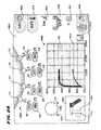
- FIG. 1is a diagrammatic view of a unified system usable in association with a family of different treatment devices for treating body sphincters and adjoining tissue regions in different regions of the body, which embodies features of the invention;
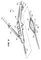
- FIG. 2is a perspective view, with portions broken away, of one type of treatment device usable in association with the system shown in FIG. 1 to treat tissue in the upper gastro-intestinal tract, the treatment device having an operative element for contacting tissue shown in a collapsed condition;
- FIG. 3is a perspective view, with portions broken away, of the device shown in FIG. 2 , with the operative element shown in an expanded condition;
- FIG. 4is a perspective view, with portions broken away, of the device shown in FIG. 2 , with the operative element shown in an expanded condition and the electrodes extended for use;
- FIG. 5is a perspective view of another type of treatment device usable in association with the system shown in FIG. 1 to treat tissue in the lower gastro-intestinal tract, the treatment device having an array of electrodes shown in a retracted position;
- FIG. 6is a perspective view of the device shown in FIG. 5 , with the array of electrodes shown in their extended position;
- FIG. 7is a perspective view of a kit containing a device, such as shown in FIG. 2 or 5 , and a usage key card;
- FIG. 8is an enlarged, mainly schematic view of the usage key card shown in FIG. 7 , embodied as a floppy disk, and also showing the pre-formatted files it contains;
- FIG. 9is a schematic view of a controller, which the system shown in FIG. 1 incorporates, showing the pre-programmed rules by which information contained on the usage key card shown in FIGS. 7 and 8 is read and processed;
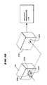
- FIG. 10is a schematic view of another processing device that reads information from the usage key card shown in FIG. 7 , for further processing;
- FIGS. 11A and 11Bare, respectively, left and right perspective views of one embodiment of an integrated device incorporating features of the system shown in FIG. 1 and usable with either treatment device shown in FIG. 2 or 5 for treating body sphincters and adjoining tissue regions, and also having a graphical user interface;
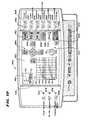
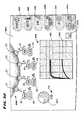
- FIG. 12is a front view of the device shown in FIGS. 11A and 11B showing the components of the graphical user interface;
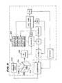
- FIG. 13is a flow chart showing further details of the pre-programmed rules by which information contained on the usage key card shown in FIGS. 7 and 8 is read and processed to set up use of a selected treatment device with the device shown in FIGS. 11A , 11 B, and 12 ;
- FIG. 14is a representative SETUP display that can be implemented by the graphical user interface of the device shown in FIGS. 11A , 11 B, and 12 , following the pre-programmed rules shown in FIG. 13 , as part of monitoring and controlling the use of a selected treatment device;
- FIG. 15is a flow chart showing further details of the pre-programmed rules implemented in concert with the pre-programmed rules shown in FIG. 13 , by which information contained on the usage key card and provided by a selected treatment device is read and processed to enable use of the selected treatment device in association with the device shown in FIGS. 11A , 11 B, and 12 ;
- FIG. 16is a representative EXCHANGE display that can be implemented by the graphical user interface of the device shown in FIGS. 11A , 11 B, and 12 , following the pre-programmed rules shown in FIGS. 13 and 15 , as part of monitoring and controlling the use of a selected treatment device;
- FIGS. 17 to 24are views of a graphical user interface that can be implement by the device shown in FIGS. 11A , 11 B, and 12 , for controlling the use and operation of the treatment device shown in FIGS. 2 to 4 ;
- FIGS. 25 to 30are views of a graphical user interface that can be implement by the device shown in FIGS. 11A , 11 B, and 12 , for controlling the use and operation of the treatment device shown in FIGS. 5 and 6 ;
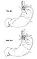
- FIGS. 31 and 32are side views, with portions broken away and in section, showing deployment of the treatment device shown in FIGS. 2 to 4 in the upper gastro-intestinal tract to treat dysfunction of the lower esophageal sphincter;
- FIG. 33is a side view, with portions broken away and in section, showing deployment of the treatment device shown in FIGS. 5 and 6 in the lower gastro-intestinal tract to treat sphincter dysfunction in the anal canal.
- This Specificationdiscloses various systems and methods for treating dysfunction of sphincters and adjoining tissue regions in the body.
- the systems and methodsare particularly well suited for treating these dysfunctions in the upper and lower gastrointestinal tract, e.g., gastro-esophageal reflux disease (GERD) affecting the lower esophageal sphincter and adjacent cardia of the stomach, or fecal incontinence affecting the internal and external sphincters of the anal canal.
- GDDgastro-esophageal reflux disease
- the disclosed systems and methodsare applicable for use in treating other dysfunctions elsewhere in the body, and dysfunctions that are not necessarily sphincter-related.
- the various aspects of the inventionhave application in procedures requiring treatment of hemorrhoids, or urinary incontinence, or restoring compliance to or otherwise tightening interior tissue or muscle regions.
- the systems and methods that embody features of the inventionare also adaptable for use with systems and surgical techniques that catheter-based and not necessarily catheter-based.
- FIG. 1shows a unified system 24 for diagnosing and/or treating dysfunction of sphincters and adjoining tissue in different regions of the body.
- the system 24is configured to diagnose and treat dysfunction in at least two distinct sphincter regions within the body.
- the targeted sphincter regionscan vary.
- one regioncomprises the upper gastro-intestinal tract, e.g., the lower esophageal sphincter and adjacent cardia of the stomach.
- the second regioncomprises the lower gastrointestinal tract, e.g., in the intestines, rectum and anal canal.
- the system 24includes a family of treatment devices 26 a and 26 b .
- Each device 26 a and 26 bcan be specifically configured according to the physiology and anatomy of the particular sphincter region which it is intended to treat. The details of construction of each device 26 a and 26 b will be generally described later for purposes of illustration, but are not material to the invention.
- Each device 26 a / 26 bcarries an operative element 36 a and 36 b .
- the operative element 36 a and 36 bcan be differently configured according to the physiology and anatomy of the particular sphincter region which it is intended to treated. Still, if the anatomy and physiology of the two treatment regions are the same or similar enough, the configuration of the operative elements 36 a and 36 b can be same or essentially the same.
- the operative elements 36 a and 36 bfunction in the system 10 to apply energy in a selective fashion to tissue in or adjoining the targeted sphincter region.
- the applied energycreates one or more lesions, or a prescribed pattern of lesions, below the surface of the targeted region.
- the subsurface lesionsare desirably formed in a manner that preserves and protects the surface against thermal damage.
- Natural healing of the subsurface lesionsleads to a physical tightening of the targeted tissue.
- the subsurface lesionscan also result in the interruption of aberrant electrical pathways that may cause spontaneous sphincter relaxation.
- the treatmentcan restore normal closure function to the sphincter region 18 .
- the system 24includes a generator 38 to supply the treatment energy to the operative element 36 a / 36 b of the device 26 a / 26 b selected for use.
- the generator 38supplies radio frequency energy, e.g., having a frequency in the range of about 400 kHz to about 10 mHz.
- radio frequency energye.g., having a frequency in the range of about 400 kHz to about 10 mHz.
- other forms of energycan be applied, e.g., coherent or incoherent light; heated or cooled fluid; resistive heating; microwave; ultrasound; a tissue ablation fluid; or cryogenic fluid.
- a selected device 26 a / 26 bcan be individually coupled to the generator 38 via a cable 10 to convey the generated energy to the respective operative element 36 a / 36 b.
- the system 24preferably also includes certain auxiliary processing equipment.
- the processing equipmentcomprises an external fluid delivery apparatus 44 and an external aspirating apparatus 46 .
- a selected device 26 a / 26 bcan be connected via tubing 12 to the fluid delivery apparatus 44 , to convey processing fluid for discharge by or near the operative element 36 a / 36 b .
- a selected device 26 a / 26 bcan also be connected via tubing 14 to the aspirating apparatus 46 , to convey aspirated material from or near from the operative element 36 a / 36 b for discharge.
- the system 24also includes a controller 52 .
- the controller 52which preferably includes a central processing unit (CPU), is linked to the generator 38 , the fluid delivery apparatus 44 , and the aspirating apparatus 46 .
- the aspirating apparatus 46can comprise a conventional vacuum source typically present in a physician's suite, which operates continuously, independent of the controller 52 .
- the controller 52governs the power levels, cycles, and duration that the radio frequency energy is distributed to the particular operative element 36 a / 36 b , to achieve and maintain power levels appropriate to achieve the desired treatment objectives.
- the controller 52also desirably governs the delivery of processing fluid and, if desired, the removal of aspirated material.
- the controller 52includes an input/output (I/O) device 54 .
- the I/O device 54allows the physician to input control and processing variables, to enable the controller to generate appropriate command signals.
- the I/O device 54also receives real time processing feedback information from one or more sensors associated with the operative element (as will be described later), for processing by the controller 52 , e.g., to govern the application of energy and the delivery of processing fluid.
- the I/O device 54also includes a graphical user interface (GUI), to graphically present processing information to the physician for viewing or analysis. Further details regarding the GUI will be provided later.
- GUIgraphical user interface
- the structure of the operative element 36can vary. Various representative embodiments will be described.
- FIGS. 2 to 4show a catheter-based device 26 a for treating sphincter regions in the upper gastrointestinal tract, and more particularly, the lower esophageal sphincter and adjoining cardia of the stomach to treat GERD.
- the device 26 aincludes a flexible catheter tube 30 that carries a handle 28 at its proximal end. The distal end of the catheter tube 30 carries the operative element 36 a.
- the operative element 36 acomprises a three-dimensional basket 56 .
- the basket 56includes one or more spines 58 , and typically includes from four to eight spines 58 , which are assembled together by a distal hub 60 and a proximal base 62 .
- an expandable structure 72comprising a balloon is located within the basket 56 .
- the balloon structure 72can be made, e.g., from a Polyethylene Terephthalate (PET) material, or a polyamide (non-compliant) material, or a radiation cross-linked polyethylene (semi-compliant) material, or a latex material, or a silicone material, or a C-Flex (highly compliant) material.
- the balloon structure 72presents a normally, generally collapsed condition, as FIG. 2 shows.
- the basket 56is also normally collapsed about the balloon structure 72 , presenting a low profile for deployment into the esophagus.
- a catheter tube 30includes an interior lumen, which communicates with the interior of the balloon structure 72 .
- a fitting 76e.g., a syringe-activated check valve
- the fitting 76communicates with the lumen.
- the fitting 76couples the lumen to a syringe 78 (see FIG. 3 ).
- the syringe 78injects fluid under pressure through the lumen into the balloon structure 72 , causing its expansion.
- Expansion of the balloon structure 72urges the basket 56 to open and expand (see FIG. 3 ).
- the force exerted by the balloon structure 72when expanded, is sufficient to exert an opening or dilating force upon the tissue surrounding the basket 56 (see FIG. 31 ).
- Each spine 58carries an electrode 66 (see FIG. 4 ).
- each electrode 66is carried within the tubular spine 58 for sliding movement.
- Each electrode 66slides from a retracted position, withdrawn in the spine 58 (shown in FIG. 3 ) and an extended position, extending outward from the spine 58 (see FIG. 4 ) through a hole in the spine 58 .
- a push-pull lever 68 on the handle 28is coupled by one or more interior wires to the sliding electrodes 66 .
- the lever 68controls movement electrodes between the retracted position (by pulling rearward on the lever 68 ) and the extended position (by pushing forward on the lever 68 ).
- the electrodes 66have sufficient distal sharpness and strength, when extended, to penetrate a desired depth into tissue the smooth muscle of the lower esophageal sphincter 18 or the cardia of the stomach 16 (see FIG. 32 ).
- the desired depthcan range from about 4 mm to about 5 mm.
- the electrodes 66are formed of material that conducts radio frequency energy, e.g., nickel titanium, stainless steel, e.g., 304 stainless steel, or a combination of nickel titanium and stainless steel.
- an electrical insulating material 70is coated about the proximal end of each electrode 66 .
- the material 70insulates the mucosal surface of the esophagus 10 or cardia 20 from direct exposure to the radio frequency energy. Thermal damage to the mucosal surface is thereby avoided.
- the mucosal surfacecan also be actively cooled during application of radio frequency energy, to further protect the mucosal surface from thermal damage.
- At least one temperature sensor 80is associated with each electrode.
- One temperature sensor 80senses temperature conditions near the exposed distal end of the electrode 66
- a second temperature sensor 80is located on the corresponding spine 58 , which rests against the mucosal surface when the balloon structure 72 is inflated.
- the external fluid delivery apparatus 44is coupled via tubing 12 (see FIG. 1 ) to connector 48 (see FIG. 4 ), to supply cooling liquid to the targeted tissue, e.g., through holes in the spines.
- the external aspirating apparatus 46is coupled via tubing 14 (see FIG. 1 ) to connector 50 (see FIG. 4 ), to convey liquid from the targeted tissue site, e.g., through other holes in the spine or elsewhere on the basket 56 .
- the controller 52can govern the delivery of processing fluid and, if desired, the removal of aspirated material.
- the controller 52can condition the electrodes 66 to operate in a monopolar mode. In this mode, each electrode 66 serves as a transmitter of energy, and an indifferent patch electrode (described later) serves as a common return for all electrodes 66 . Alternatively, the controller 52 can condition the electrodes 66 to operate in a bipolar mode. In this mode, one of the electrodes comprises the transmitter and an other electrode comprises the return for the transmitted energy.
- the bipolar electrode pairscan electrodes 66 on adjacent spines, or electrodes 66 spaced more widely apart on different spines.
- FIGS. 5 and 6show a representative embodiment for device 26 b , which takes the form of a hand manipulated device 302 for treating sphincter regions in the lower gastrointestinal tract, and more particularly, the internal and/or external sphincter muscles in the anal canal to treat fecal incontinence.
- the device 302includes a hand grip 304 that carries the operative element 36 b.
- the operative element 36 btakes the form of a hollow, tubular barrel 306 made from a transparent, molded plastic material.
- the barrel 306terminates with a blunt, rounded distal end 308 to aid passage of the barrel 306 through the anal canal, without need for a separate introducer.
- the hand grip 304includes a viewing port 312 for looking into the transparent, hollow interior of the barrel 306 , to visualize surrounding tissue.
- An array of needle electrodes 316are movably contained in a side-by-side relationship along an arcuate segment of the barrel 306 .
- the needle electrodes 316occupy an arc of about 67.5 degrees on the barrel 306 .
- the needle electrodes 316are mechanically linked to a finger-operated pull lever 318 on the hand grip 304 . By operation of the pull lever 318 , the distal ends of the needle electrodes 316 are moved between a retracted position ( FIG. 5 ) and an extended position ( FIG. 6 ).
- An electrical insulating material 344is coated about the needle electrodes 316 (see FIG. 6 ), except for a prescribed region of the distal ends, where radio frequency energy is applied to tissue.
- the generator 38is coupled via the cable 10 to a connector 352 , to convey radio frequency energy to the electrodes 316 .
- the physiciangrasps the hand grip 304 and guides the barrel 306 into the anal canal 320 .
- the pull lever 318is in the neutral position and not depressed, so the needle electrodes 316 occupy their normal retracted position.
- the physicianvisualizes the pectinate (dentate) line through the barrel 306 .
- the physicianpositions the distal ends of the needle electrodes 316 at a desired location above the pectinate (dentate) line.
- a fiberopticcan also be inserted into the barrel 306 to provide local illumination, or the physician can wear a headlamp for this purpose.
- the physiciandepresses the pull lever 318 (as FIG. 33 shows).
- the needle electrodes 316advance to their extended positions.
- the distal ends of the electrodes 316pierce and pass through the mucosal tissue into the muscle tissue of the target sphincter muscle.
- the distal end of the electrodes 316are shown penetrating the involuntary, internal sphincter muscle 322 .
- the physiciancommands the controller 52 to apply radio frequency energy through the needle electrodes 316 .
- the energycan be applied simultaneously by all electrodes 316 , or in any desired sequence.
- the external fluid delivery apparatus 44is coupled via tubing 12 to a connector 348 to convey a cooling liquid, e.g., through holes in the barrel 306 , to contact tissue at a localized position surrounding the electrodes 316 .
- the external aspirating apparatus 46is coupled via tubing 14 to a connector 350 to convey liquid from the targeted tissue site, e.g., through an aspiration port 358 in the distal end 308 of the barrel 306 (see FIGS. 5 and 6 ).
- the barrel 306also preferably carries temperature sensor 364 , one of which is associated with each needle electrode 316 .
- the sensors 364sense tissue temperature conditions in the region adjacent to each needle electrode 316 .
- the distal end of each needle electrode 316also carries a temperature sensor 372 (see FIG. 6 ).
- Each device 26 a and 26 bpreferably forms an integrated construction intended for a single use and subsequent disposal as a unit.
- the controller 52includes a module 64 that controls use of each device 26 a and 26 b.
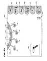
- each device 26 a / 26 bis supplied as part of a kit 200 that includes, together with the device 26 , a usage key card 202 .
- the kit 200packages the device 26 a / 26 b and usage key card 202 as a unitary, single use item in a sterile fashion within peripherally sealed sheets of plastic film material that are torn or peeled away at the instance of use.
- the presence of the device 26 a / 26 b and user key card 200 packaged together in the kit 200verifies to the physician or user that device 26 a / 26 b is sterile and has not be subjected to prior use. The physician or user is thereby assured that the device 26 a / 26 b meets established performance and sterility specifications. No unused device 26 a / 26 b is supplied in the kit 200 without a usage key card 202 , and vice versa.
- the usage key card 202 for each device 26 a / 26 bincorporates a storage medium 204 that is readable by the module 64 .
- the storage medium 204contains information that enables at least three use control and monitoring functions.
- the first use control and monitoring function of the usage key card 202occurs prior to use of the selected device 26 a / 26 b in association with the generator 38 .
- the physicianmust first present the usage key card 202 for reading by the module 64 .
- the controller 52must then find that the usage key card 202 meets the criteria necessary for its registration by the controller 52 .
- the criteriaare designed to indicate the absence of a prior use, either in absolute terms or in terms of a period of use outside a predetermined time period.
- the controller 52will not register the usage key card 202 , and the controller 52 will also not enable use of the generator 38 in association with the selected device 26 a / 26 b . Further details of the registration function of the controller 52 will be described later.
- the second use control and monitoring functionoccurs if the criteria are met and registration of the usage key card 202 occurs.
- the second use control and monitoring functionidentifies the particular type of device 26 a / 26 b that has been selected for use.
- the second use and control functionconditions the controller 52 to implement only those control algorithms and operator interface displays particular to the selected device 26 a / 26 b . Further details of this control aspect will be described later.
- the third use control and monitoring function of the usage key card 202occurs during permitted use of the selected device 26 / 26 b in association with the generator 38 .
- the storage medium 204 of the usage key card 202remains in the module 64 and receives, via the module 64 , data generated by the controller 52 recording operating parameters and performance of the selected device 26 a / 26 b .
- the storage medium 204 of the usage key card 202retains and organizes the data for further off-line storage and processing. Further details of the data retention function will be described later.
- the usage key card 202can be variously configured.
- the usage key card 202comprises a computer-readable storage medium 204 housed within a conventional 3.5 inch floppy disk 206 .
- the module 64comprises a conventional floppy disk drive 208 (see FIG. 9 ) capable of reading data from and downloading data to the storage medium 204 of the disk 206 .
- the usage key card 202can take the form of a PC card, flash memory device, or magnetic card.
- the module 64comprises a data reading and writing device compatible with the storage medium of the card 202 .
- the storage medium 204 of the usage key card 202contains at least three pre-formatted files 210 , 226 , and 212 .
- the first file 210contains a unique identification code 214 capable of being read by the module 64 and registered by the controller 52 .
- the second file 226contains another identification code that specifies the particular type of device 26 a / 26 b that has been selected, which thereby indicates the desired treatment protocol that has been selected.
- the third file 212is formatted to receive and retain operational and performance data generated by the controller 52 to create from it a procedure log 220 .
- the identification code 214 contained in the first file 210is created to be unique to the particular usage key card 202 . That is, each usage key card 202 contains its own unique identification code 214 . No two usage key cards share the same identification code 214 .
- the unique identification code 214can comprise, e.g., a serial number uniquely assigned to the particular device 26 a / 26 b found in the kit 200 , or any other unique code that is not repeated for any other usage key card 202 .
- the code 214itself can comprise letters, numbers, or combinations thereof.
- the module 64reads the identification code 214 off the usage key card 202 for input to the controller 52 .
- This identification codewill be called the “instant identification code.”
- the controller 54constructs and maintains in non-volatile memory a use table 216 .
- the use table 216contains all prior identification codes that meet the criteria to be registered by the controller 52 . These identification codes will be called the “registered identification codes.”
- the controller 52compares the instant identification code 214 to all registered identification codes contained in the table 216 . In the absence of a match between the instant identification code and any registered identification code, the controller 52 updates the table, i.e., the controller registers the instant identification code by adding it to the table 216 . Upon registering the usage key card 202 , the controller 52 also enables use of generator 38 in association with the selected device 26 a / 26 b.
- the controller 52does not add the duplicate identification code to the table 216 and does not enable use of the generator 38 in association with any device 26 .
- the controller 52outputs to the GUI 54 notice of prior use.
- the controller 52maintains for each registered identification code in the table 216 a time record 218 .
- the time record 218contains a value reflecting the period of time during which energy was applied by the generator 38 during the previous permitted use.
- the controller 52ascertains whether the time period of previous use contained in the record 218 is less than a prescribed maximum time period, e.g., 45 minutes. If so, the controller 52 enables a subsequent operation of the generator 38 in association with the device 26 , but only for the time period remaining.
- the controller 52updates the time record 218 as further use occurs.
- the controller 52preferably outputs to the GUI the time period of permitted use remaining.
- the controller 52If the controller 52 ascertains that the time period of previous use equals or exceeds the prescribed maximum time period, the controller 52 does not enable use of the generator 38 . Preferably, the controller 52 outputs to the GUI notice of prior use.
- the second file 226 contained in the storage medium 204 of the usage key card 202is created to uniquely identify the particular configuration and intended use of the device 26 a or 26 b that has been selected.
- the file 226contains a first identification code 228 a if device 26 a has been selected.
- the file 226contains a second identification code 228 b if device 26 b has been selected.
- the codes 228 a and 228 bcan comprise letters, numbers, or combinations thereof.
- the codes 228 a / 228 bcan identify the type of device 26 a / 26 b in terms of its operational characteristics, the inclusion of temperature sensing, and reuse criteria (e.g., no reuse after a single use, or multiple uses permitted up a prescribed maximum number of uses, or multiple uses permitted up to a maximum time period of use, or multiple uses permitted up to a maximum application of RF energy).
- the controller 52can compare the device characteristics with the operational characteristics of the controller 52 and generator 38 , and disable operation of the device 26 should the characteristics of the device 26 be incompatible with the characteristics of the controller 52 and/or generator 38 .
- the module 64reads the identification code 228 a or 228 b off the usage key card 202 for input to the controller 52 .
- the controller 54implements only those particular control algorithms intended for the selected device 26 a / 26 b .
- the controller 52can, in response to reading the identification code 228 a or 228 b also condition the GUI 54 to display the desired images and data formats, which change depending upon the treatment procedure using the selected device 26 a / 26 b (e.g., treatment of GERD using the device 26 a or the treatment of fecal incontinence using the device 26 b ).
- the system 10accommodates different control schemes and different graphical interfaces in support of different treatment protocols.
- the third file 212 contained on the storage medium 204 of the usage key card 202is formatted to receive, via the module 64 , data that is generated by the controller 52 during permitted use of the selected device 26 a / 26 b in association with the generator 38 .
- the file 212retains the data in a formatted array according to pre-programmed rules to create a procedure log 220 (see FIG. 10 ).
- the content of the formatted log 220can vary.
- the log 220can document, by date of treatment and number of treatments, the coagulation level (i.e., the depth at which the electrodes are inserted), the time duration of energy application, the magnitude of energy delivered by each electrode, and the coolant flow rate.
- the procedure log 220can also record at pre-established intervals (e.g., every 5 seconds) the temperatures of the electrodes and surrounding tissue, along other parameters, e.g., sensed impedance and power delivered by each electrode.
- the procedure log 220preferably records these values in a pre-formatted data base format, to enable import of the values as data base items for storage, processing, and retrieval by an off-line data processing device 222 having a compatible data base processing application.
- the off-line data processing device 222reads processing log data from the usage key card 202 (via a floppy disk drive 230 or otherwise compatible reading device).
- the device 222can process the data in various ways according to the rules of the data processing application.
- the device 222can, e.g., create a print-formatted record of the procedure log 220 for printing in a hard copy version.
- the device 222can also, e.g., process the procedure logs for multiple devices and patients, to create historical patient treatment records, patient reimbursement records, and the like for storage or retrieval.
- the device 222thereby makes possible the establishment and maintenance of an archival patient data base by processing individual procedure logs.
- the kit 200can also include a label 224 that is pre-applied or that can be applied by the physician to the usage key card 202 .
- the label 224receives manually transcribed, visually readable information pertaining to the usage key card 202 , e.g., the name of the patient being treated by the device 26 , the date of treatment, and the like. In this way, usage key cards 202 can itself be physically stored and indexed.
- the kit 200can also include instructions 232 for using the usage key card 202 in the fashion described.
- the instructions 232can instruct the physician as to the need for having the usage key card 202 read by the module 64 , in order to enable use of the device 26 in association with the generator 38 .
- the instructions 232can also instruct the physician regarding the content of the procedure log and the subsequent off-line processing options that are available.
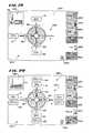
- the radio frequency generator 38 , the controller 52 with I/O device 54 , and the fluid delivery apparatus 44are integrated within a single housing 400 .
- the I/O device 54includes input connectors 402 , 404 , and 406 .
- the connector 402accepts an electrical connector 408 , to which the selected treatment device 26 a / 26 b is electrically coupled for use.
- the connector 404accepts an electrical connector 410 coupled to a patch electrode 412 (for mono-polar operation).
- the connector 406accepts an pneumatic connector 414 coupled to a conventional foot pedal 416 , when, when depressed, causes the delivery of radio frequency energy to the electrodes 66 on the device 26 .
- These connectors 402 , 404 , and 406couple these external devices to the controller 52 .
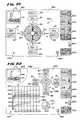
- the I/O device 54also couples the controller 52 to an array of membrane keypads 422 and other indicator lights on the housing 400 , for entering and indicating parameters governing the operation of the controller 52 .
- the keypads 422 and indicatorsinclude:
- Standby/Ready Button 430which allows switching from one mode of operation to another, as will be described later.
- Standby/Ready Indicator 432which displays a green light after the device 400 passes a self test upon start up.
- RF On Indicator 434which displays a blue light when radio frequency energy is being delivered.
- Fault Indicator 436which displays a red light when an internal error has been detected. No radio frequency energy can be delivered when the Fault Indicator 436 is illuminated.
- Target Duration Keys 438which allow increases and decreases in the target power duration at the start or during the course of a procedure.
- Target Temperature Keys 440which allow increases and decreases in the target temperature at the start or during the course of a procedure.
- Maximum Power Keys 442which allow increases and decreases in the maximum power setting at the start or during the course of a procedure.
- Channel Selection Keys 444which allow selection of any or all power channels.
- Coagulation Level Keys 446which manually increases and decreases the magnitude of the indicated depth of insertion of the electrodes of the device 26 a within the esophagus. This depth is determined, e.g., by visually gauging the measured markings along the length of the catheter tube of the treatment device 26 a .
- the coagulation levelcan be automatically detected by, e.g., placing optical, mechanical, or magnetic sensors on an associated mouth piece inserted into the esophagus, which detect and differentiate among the measured markings along the catheter tube of the treatment device 26 a to read the magnitude of the depth of insertion.
- Flow Rate and Priming Keys 448which allow for selection of three internally calibrated flow rates, low (e.g., 15 ml/min), medium (e.g., 30 ml/min), and high (e.g., 45 ml/min). Pressing and holding the “Up” key activates the pump at a high flow rate for priming, overruling the other flow rates until the “Up” key is released.
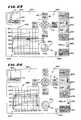
- the I/O device 54also couples the controller 52 to a display microprocessor 474 (see FIG. 11A ).
- the microprocessor 474comprises, e.g., a dedicated Pentium7 ⁇ based central processing unit.
- the controller 52transmits data to the microprocessor 474 , and the microprocessor 474 acknowledges correct receipt of the data and formats the data for meaningful display to the physician.
- the dedicated display microprocessor 474exerts no control over the controller 52 .
- the controller 52comprises an 68HC11 processor having an imbedded operating system.
- the controller 52can comprise another style of processor, and the operating system can reside as process software on a hard drive coupled to the CPU, which is down loaded to the CPU during system initialization and startup.
- the display microprocessor 474is coupled to a graphics display monitor 420 in the housing 400 .
- the controller 52implements through the display microprocessor 474 the graphical user interface, or GUI, which is displayed on the display monitor 420 .
- the GUIcan be realized, e.g., as a VISUAL BASICJ language program implemented by the microprocessor 474 using the MS WINDOWSJ or NT application and the standard WINDOWS 32 API controls, e.g., as provided by the WINDOWSJ Development Kit, along with conventional graphics software disclosed in public literature.
- the display microprocessor 474is also itself coupled to the floppy disk drive 426 , previously described as floppy disk module 208 ( FIG. 9 ).
- the display microprocessor 474can also be coupled to a keyboard, printer, and include one or more parallel port links and one or more conventional serial RS-232C port links or EthernetTM communication links.
- the graphics display monitor 420can comprise an active matrix LCD display screen located between the membrane keypads 422 and other indicators on the front panel.
- the GUI 424is implemented by showing on the monitor 420 basic screen displays.
- these displayssignify four different operating modes: Start-Up, Standby, Ready, RF-On, and Pause.
- the operating systemUpon boot-up of the CPU (see FIG. 13 ), the operating system implements the START-UP function 510 for the GUI 424 .
- the GUI 424displays an appropriate start-up logo and title image (not shown), while the controller 52 performs a self-test.
- the controller 52Upon completion of the START-UP function (see FIG. 13 ), the controller 52 conducts a CHECK function 512 .
- the function 512checks for the presence of a usage key card 202 in the floppy disk drive 426 . As before described, a valid usage key card 202 is a prerequisite for using a given treatment device 26 .
- FIG. 14shows a representative SETUP prompt 500 .
- the SETUP prompt 500leads the operator in a step-wise fashion through the tasks required to enable use of the generator 38 .
- a first graphic fielddisplays one or more icons and/or alpha-numeric indicia 502 that prompt the operator to connect the electrical connector 42 of the treatment device 26 to the connector cable 408 .
- a second graphic fielddisplays one or more icons and/or alpha-numeric indicia 504 that prompt the operator to insert a valid user key card 202 (i.e., floppy disk).
- a third graphic fielddisplays one or more icons and/or alpha-numeric indicia 506 that prompt the user to select the standby-ready button 430 on the housing 400 (see FIG. 12 ).
- the controller 52With the selected treatment device 26 a / 26 b connected and a user key card 202 inserted in the floppy disk drive 426 , and the standby-ready button 430 pressed, the controller 52 reads the device identification code 228 a or 228 b on the user key card 202 . In this way, the controller 52 ascertains which device 26 a or 26 b has been selected for use. Based upon this input, the controller 52 proceeds to execute the preprogrammed control and graphical GUI command functions for the device 26 a and 26 b that the user key card 202 indicates has been selected.
- the GUI 424displays an appropriate start-up logo and title image for the device 26 a .
- the GUI 424displays an appropriate start-up logo and title image for the device 26 b.
- the controller 52After the start-up logo and title image for the selected device 26 a / 26 b has been displayed, the controller 52 remains in the STAND-BY mode 508 (see FIG. 15 ). In the STAND-BY mode 508 , the controller 52 performs a DEVICE HARDWARE CHECK function 540 .
- the same DEVICE HARDWARE CHECK function 540is performed regardless of the device 26 a / 26 b selected.
- the DEVICE HARDWARE CHECK function 540looks for the presence or absence of a preestablished electrical identification signal from the device 26 a / 26 b itself, to confirm by a different mechanism the identity of the device 26 a / 26 b indicated by the user key card 202 .
- the DEVICE HARDWARE CHECK function 540can be accomplished is various ways.
- the device 26 a and 26 bcan include within its handle an analog electrical element (e.g., a capacitor or resistor) or a solid state element (micro-chip, ROM, EEROM, EPROM, or non volatile RAM) that generates an electrical value that differs depending upon the device 26 a or 26 b is present.
- the controller 52reads this electrical value through the electrical connector 408 , to which the selected treatment device 26 a / 26 b is coupled for use.
- the DEVICE HARDWARE CHECK function 540provides a redundant, fail safe confirmation of the identification of the device 26 a / 26 b provided by the user key card 202 .
- the controller 52If the identity of the device 26 a / 26 b based upon the DEVICE HARDWARE CHECK function 540 does not correspond with the identity of the device 26 a / 26 b based upon the user key card 202 , the controller 52 returns to the SETUP prompt 500 ( FIG. 14 ) described earlier, to repeat the identification process.
- the controller 52executes the REGISTRATION function 514 for the device 26 a / 26 b (see FIG. 15 ), to determine whether the user key card 202 inserted in the drive 426 contains a valid identification code 214 .
- the same REGISTRATION function 514is performed regardless of the device 26 a / 26 b selected.
- the identification code 214will not be deemed valid when the code already exists in the use table 216 of the controller 52 with a time record 218 equal to or greater than the prescribed maximum, thereby indicating a completed prior use of the selected device 26 a / 26 b .
- the REGISTRATION function 514commands the display microprocessor 474 to generate an EXCHANGE prompt 516 on the graphics display monitor 420 .
- FIG. 16shows a representative EXCHANGE prompt 516 .
- the EXCHANGE prompt 516leads the operator in a step-wise fashion through the tasks of replacing the previously used selected device 26 a / 26 b and its key card 202 with a new selected device 26 a / 26 b and its associated key card 202 .
- a first graphic fielddisplays one or more icons and/or alpha-numeric indicia 518 that prompt the operator to disconnect the electrical connector 42 of the previously used treatment device 26 a / 26 b and to connect a new treatment device 26 a / 26 b .
- a second graphic fielddisplays one or more icons and/or alpha-numeric indicia 520 that prompt the operator to remove the old user key card 202 and insert the new key card 202 that accompanied the new selected treatment device 26 a / 26 b in the kit 200 .
- a third graphic fielddisplays one or more icons and/or alpha-numeric indicia 522 that prompt the user to again select the standby-ready button 430 on the housing 400 .
- selection of the standby-ready button 430causes the controller 52 to again enter the STAND-BY mode 508 , and again execute the DEVICE HARDWARE CHECK function 540 and the REGISTRATION function 514 (see FIG. 15 ).
- the controller 52Upon completion of the START-UP operation, and successful registration of the usage key card 202 , the controller 52 proceeds to condition the generator and ancillary equipment to proceed step-wise through a sequence of operational modes.
- the operational modeshave been preprogrammed to achieve the treatment protocol and objective of the selected device 26 a / 26 b .
- the conduct of these operational modes and the appearance of the graphical user interface that guides and informs the user during the course of the selected procedurecan differ between devices 26 a and 26 b.
- GUI displays for the upper gastro-intestinal procedurei.e., for the device 26 a
- UGUIwhich are shown in FIGS. 12 and 17 to 24
- LGUIwhich are shown in FIGS. 25 to 30 .
- the controller 52When the device identification code 228 a is read on the usage key card 202 (i.e., indicating selection of the device 26 a for use in the upper gastro-intestinal tract), the controller 52 conditions the UGUI to display the Standby screen shown in FIG. 17 .
- the controller 52When the device identification code 228 b is read on the usage key card 202 (i.e., indicating selection of the device 26 b for use in the lower gastro-intestinal tract), the controller 52 conditions the LGUI to display the Standby screen shown in FIG. 25 .
- a Screen Icon 450appears in the upper left hand corner to indicate the operating condition of the treatment device 26 a .
- the icon 450also indicates the position of the treatment device inside or outside the esophagus.
- the Screen Icon 450is displayed in the lower left hand corner, to indicate the operating condition of the treatment device 26 b.
- the physiciancan couple the source of cooling liquid to the appropriate port on the handle of the device 26 a / 26 b (as previously described) and load the tubing leading from the source of cooling liquid (e.g., a bag containing sterile water) in the pump rotor 428 .
- the physiciancan also couple the aspiration source 46 to the appropriate port on the handle of the treatment device 26 a / 26 b (as also already described).
- the physiciancan also couple the patch electrode 412 and foot pedal 416 .
- UGUIFIG. 17
- parameter iconsdesignating target duration 452 , target temperature 454 , maximum power 456 , channel selection 458 , coagulation level 460 , and flow rate/priming 462 .
- These iconsare aligned with, respectively, the corresponding Target Duration Keys 438 , Target Temperature Keys 440 , Maximum Power Keys 442 , Channel Selection Keys 444 , Coagulation Level Keys 446 , and Flow Rate and Priming Keys 448 .
- the icons 452 to 462indicate current selected parameter values.
- the flow rate/priming icon 462shows the selected pump speed by highlighting a single droplet image (low speed), a double droplet image (medium speed), and a triple droplet image (high speed).
- LGUI( FIG. 25 )
- comparable parameter iconsappear, except that coagulation level icon 460 in the UGUI is replaced in the LGUI by a RF cycle counter icon 461 .
- the icon 461displays a value that counts the number of RF cycles applied to the device 26 b during use. Knowing the number of electrodes that the device 26 b carries, this value is indicative of the number of lesions that are being formed.
- An animated priming stream PS(see FIG. 26 ) is displayed in the flow rate/priming icon 462 of the LGUI when the device 26 b is primed in the Standby mode.
- animated priming streams PSare displayed in the Screen Icon 450 in UGUI (see FIGS. 21 , 22 , and 23 ) and LGUI (see FIGS. 28 and 29 ) whenever the pump rotor 428 is operating, to indicate the supply of cooling fluid through the respective treatment device 26 a and 26 b.
- floppy disk icon 464In both UGUI ( FIG. 17 ) and LGUI ( FIG. 25 ), there is also a floppy disk icon 464 .
- the icon 464is illuminated when a floppy disk is inserted in the drive 426 .
- the floppy diske.g., the usage key card 202
- datacan be saved automatically after each application of radio frequency energy (as will be described later).
- Electrode Icon 466in each display UGUI and LGUI.
- the Electrode Icon 466comprises an idealized graphical image, which spatially models the particular multiple electrode geometry of the treatment device 26 a / 26 b selected to be deployed.
- the form of the Electrode Icon 466is another way the controller 52 differentiates the UGUI and LGUI.
- FIG. 17shows, in the UGUI, four electrodes are shown in the graphic image of the Icon 466 , which are spaced apart by 90 degrees. This graphic image is patterned after the geometry of the four-electrode configuration of the device 26 a , as shown in FIG. 4 .
- FIG. 25shows, in the LGUI, the four electrodes are shown in the graphic image of Icon 466 in a circumferentially spaced relationship along a partial arcuate sector. This graphic image is patterned after the arrangement of electrodes on the treatment device 26 b , as shown in FIG. 6 .
- the Icon 466presents in a spatial display the magnitude of tip temperature as actually sensed in outside box B 1 in UGUI ( FIG. 17 ) and in outside oval O 1 in LGUI ( FIG. 25 ).
- the magnitude of tissue temperatures as actually sensedare also displayed in inside box B 2 in UGUI ( FIG. 17 ) and in inside oval O 2 in LGUI ( FIG. 25 ).
- two dasheswill appear in the boxes B 1 /B 2 (see FIG. 17 ) and the ovals O 1 /O 2 .
- the controller 52prohibits advancement to the Ready screen until numeric values register in the boxes B 1 /B 2 or ovals O 1 /O 2 , as FIG. 18 and FIG. 25 show, respectively.
- the display of numeric valuesindicate that a functional treatment device 26 a / 26 b is present.
- No boxes B 1 /B 2 or ovals O 1 /O 2will appear in the Icon 466 for a given electrode if the corresponding electrode/channel has been disabled using the Channel Selection Keys 444 , as FIG. 19 shows.
- the physicianis able to manually select or deselect individual electrodes using the Selection Keys 444 in the Standby or Ready Modes, but not in the RF-On Mode.
- the controller 52can be configured to allow electrode selection while in the RF-On Mode, if desired.
- the physiciancan now deploy the treatment device 26 a / 26 b to the targeted tissue region. Once deployed, the physician extends the electrodes through mucosal tissue and into underlying smooth muscle, as FIG. 32 shows for the device 26 a and FIG. 33 shows for the device 26 b.
- the physicianpresses the Standby/Ready Button 430 to advance the controller 52 from Standby to Ready Mode.
- the controller 52commands the generator 38 to apply bursts of low level radio frequency energy through each electrode selected for operation. Based upon the transmission of these low level bursts of energy by each electrode, the controller 52 derives a local impedance value for each electrode. The impedance value indicates whether or nor the given electrode is in desired contact with submucosal, smooth muscle tissue.
- the Ready screenupdates the Screen Icon 450 of the UGUI to indicate that the treatment device 26 a is connected and deployed in the patient's esophagus.
- the Ready screen of the UGUIalso intermittently blinks the RF On Indicator 434 (see FIG. 12 ) to indicate that bursts of radio frequency energy are being applied by the electrodes.
- the Ready screenalso updates the Electrode Icon 466 to spatially display in the inside and outside boxes B 1 and B 2 the actual sensed temperature conditions.
- the Ready screenalso adds a further outside box B 3 to spatially display the derived impedance value for each electrode.
- the Ready screenintermittently blinks a portion of the image in the icon 450 to indicate that bursts of radio frequency energy are being applied by the electrodes.
- the Ready screenalso updates the Electrode Icon 466 to spatially display in the inside and outside ovals O 1 and O 2 the actual sensed temperature conditions.
- the Ready screenalso adds a further outside oval O 3 to spatially display the derived impedance value for each electrode.
- the controller 52prevents the application of radio frequency energy if any temperature reading is outside a selected range (e.g., 15 to 120 degrees C.).
- the physiciancan affect changes to the parameter values for the intended procedure.
- the controller 52automatically adjusts to take these values into account in its control algorithms.
- the corresponding target duration icon 452 , target temperature icon 454 , maximum power icon 456 , channel selection icon 458 , coagulation level icon 460 , and flow rate/priming icon 462change accordingly in the UGUI and LGUI to indicate the current selected parameter values.
- the physicianpresses the foot pedal 416 .
- the controller 52advances from Ready to RF-On Mode, provided that all sensed temperatures are within the selected range.
- the controller 52activates the pump rotor 428 . Cooling liquid is conveyed through the treatment device 26 a / 26 b into contact with mucosal tissue at the targeted site. At the same time, cooling liquid is aspirated from the treatment device 26 a / 26 b in an open loop. During a predetermined, preliminary time period (e.g. 2 to 5 seconds) while the flow of cooling liquid is established at the site, the controller 52 prevents the application of radio frequency energy.
- a predetermined, preliminary time periode.g. 2 to 5 seconds
- the controller 52applies radio frequency energy through the electrodes.
- the RF-On screenis displayed in the UGUI ( FIG. 22 ) and LGUI ( FIG. 28 ).
- the RF-On screen in both the UGUI ( FIG. 22 ) and LGUI ( FIG. 28 )displays the Screen Icon 450 , indicate that the treatment device 26 a / 26 b is connected and deployed.
- the Screen Icon 450also shows the extension of electrodes, to differentiate the RF-On Screen from the Ready Screen ( FIG. 27 ).
- the flow drop animation PSalso appears in both UGUI ( FIG. 22 ) and LGUI ( FIG. 28 ), indicating that cooling is taking place.
- a flashing radio wave animation RWalso appears in both UGUI ( FIG. 22 ) and LGUI ( FIG. 28 ), indicating that radio frequency energy is being applied.
- the RF On Indicator 434 ( FIG. 12 )is also continuously illuminated to indicate that radio frequency energy is being applied by the electrodes.
- FIG. 12shows the RF-On screen of the UGUI.
- the RF-On screenalso updates the Electrode Icon 466 to display in the boxes B 1 /ovals O 1 the actual sensed tip temperature conditions.
- the RF-On screenalso displays the derived impedance value for each electrode in the boxes B 3 /ovals O 3 .
- UGUIIn both UGUI ( FIG. 22 ) and LGUI ( FIG. 28 ), unlike the Ready or Standby screens, the surface temperature is no longer displayed in a numerical format in boxes B 2 /ovals O 2 . Instead, a circle C 1 is displayed in both UGUI and LGUI, which is color coded to indicate whether the surface temperature is less than the prescribed maximum (e.g., 45 degrees C.). If the surface temperature is below the prescribed maximum, the circle C 1 is colored an “acceptable” color, e.g., green. If the surface temperature is exceeds the prescribed maximum, the color of the circle C 1 changes to an “not acceptable” color, e.g., to red.
- the prescribed maximume.g. 45 degrees C.
- the boxes B 1 and B 3 /ovals O 1 and O 3are also color coded to indicate compliance with prescribed limits. If the tip temperature is below the prescribed maximum (e.g., 100 degrees C.), the box B 1 /oval O 1 is colored, e.g., green. If the tip temperature is exceeds the prescribed maximum, the box border thickens and the color of the box B 1 /oval O 1 changes, e.g., to red.
- the prescribed maximume.g. 100 degrees C.
- the box B 1 /oval O 1is colored, e.g., green. If the tip temperature is exceeds the prescribed maximum, the box border thickens and the color of the box B 1 /oval O 1 changes, e.g., to red.
- the box B 3 /oval O 3is colored, e.g., grey. If the impedance is outside the prescribed bounds, the box border thickens and the color of the box B 3 /oval O 3 changes, e.g., to red.
- prescribed boundse.g., between 25 ohms and 1000 ohms
- Electrode Icon 466can also display in a box or circle the power being applied to each electrode in spatial relation to the idealized image.
- the RF-On screendisplays the target duration icon 452 , target temperature icon 454 , maximum power icon 456 , channel selection icon 458 , coagulation level icon 460 (or, in LGUI, the RF cycle icon 461 ), and flow rate/priming icon 462 , indicating the current selected parameter values.
- the physiciancan alter the target duration or target temperature or maximum power and pump flow rate through the corresponding selection keys 438 , 440 , 442 , and 448 (see FIG. 12 ) on the fly, and the controller 52 and respective UGUI and LGUI instantaneously adjust to the new parameter settings.
- the controller 52does not permit change of the channel/electrode while radio frequency energy is being applied, and, for this reason, the channel selection icon 458 is dimmed.
- the RF-On screen in both UGUI ( FIG. 22 ) and LGUI ( FIG. 28 )also displays a real time line graph 468 to show changes to the temperature profile (Y-axis) over time (X-axis).
- the RF-On screenalso shows a running clock icon 470 , which changes appearance to count toward the target duration.
- a digital clock display CDis also shown, indicating elapsed time.
- the line graph 468 in both UGUI ( FIG. 22 ) and LGUI ( FIG. 28 )displays four trending lines to show the minimum and maximum surface and tip temperature readings from all active electrodes.
- the time axis(X-axis) is scaled to one of five pre-set maximum durations, depending upon the set target duration. For example, if the target duration is 0 to 3 minutes, the maximum time scale is 3:30 minutes. If the target duration is 3 to 6 minutes, the maximum time scale is 3:1 seconds, and so on.
- the line graph 468displays two background horizontal bars HB 1 and HB 2 of different colors.
- the upper bar HB 1is colored, e.g., green, and is centered to the target coagulation temperature with a spread of plus and minus 10 degrees C.
- the lower bar HB 2is colored, e.g., red, and is fixed at a prescribed maximum (e.g., 40 degrees C.) to alert potential surface overheating.
- the line graph 468also displays a triangle marker TM of a selected color (e.g., red) and with a number corresponding to the channel/electrode that is automatically turned off by the controller 52 due to operation outside the selected parameters.
- a triangle marker TMof a selected color (e.g., red) and with a number corresponding to the channel/electrode that is automatically turned off by the controller 52 due to operation outside the selected parameters.
- the circle C 1 and boxes B 1 and B 3 /ovals O 1 and O 3 for this electrode/channelare also modified in the electrode icon 466 when this situation occurs.
- the Electrode Icon 466can graphically display other types of status or configuration information pertinent to the treatment device 26 a / 26 b .
- the Electrode Icon 466can display a flashing animation in spatial relation to the idealized electrodes to constantly remind the physician that the electrode is extended into tissue. The flashing animation ceases to be shown when the electrode is retracted. The flashing animation reminds the physician to retract the electrodes before removing the treatment device 26 a / 26 b .
- the Electrode Icon 466can display another flashing animation when the expandable structure of the treatment device 26 a is expanded. The flashing animation reminds the physician to collapse the electrodes before removing the treatment device 26 a.
- the controller 52terminates the conveyance of radio frequency ablation energy to the electrodes and the RF-On screen changes into the Pause screen, due to any of the following conditions (i) target duration is reached, (ii) all channels/electrodes have an erroneous coagulation condition (electrode or surface temperature or impedance out of range), or (iii) manual termination of radio frequency energy application by pressing the foot pedal 416 or the Standby/Ready Button 430 .
- the running clock icon 470 of the Pause screen of the UGUI ( FIG. 24 ) and the LGUI ( FIG. 30 )stops to indicate total elapsed time.
- the controller 52commands the continued supply of cooling liquid through the treatment device 26 a / 26 b into contact with mucosal tissue at the targeted site.
- cooling liquidis aspirated from the treatment device 26 a / 26 b in an open loop. This flow of cooling liquid continues for a predetermined time period (e.g. 2 to 5 seconds) after the supply of radio frequency ablation energy is terminated, after which the controller 52 stops the pump rotor 428 .
- the Pause screen for the UGUI ( FIG. 24 ) and LGUI ( FIG. 30 )is in most respects similar to the RF-On screen for the respective device 26 a / 26 b .
- the Pause screendisplays the Screen Icon 450 , to indicate that the treatment device 26 a is connected and deployed in the patient's esophagus. However, the flashing radio wave animation is not present, indicating that radio frequency energy is no longer being applied.
- the Screen Icon 450is blanked.
- the Pause screen for the UGUI( FIG. 24 ) also updates the Electrode Icon 466 to display in the boxes B 1 and B 3 the actual sensed tip temperature and impedance conditions. However, no background color changes are registered on the Pause screen, regardless of whether the sensed conditions are without or outside the prescribed ranges. In the LGUI ( FIG. 30 ), no values are displayed in the ovals O 1 and O 3 .
- the Pause screen for the UGUI ( FIG. 24 ) and the LGUI ( FIG. 30 )continues to display the target duration icon 452 , target temperature icon 454 , maximum power icon 456 , channel selection icon 458 , coagulation level icon 460 (or, in LGUI, the RF cycle icon 461 ), and flow rate/priming icon 462 , indicating the current selected parameter values.
- the real time temperature line graph 468continues to display the four trending lines, until the target duration is reached and five additional seconds elapse, to show the drop off of electrode temperature.
- pressing the Standby/Ready button 430returns the device 400 from the Pause back to the Ready mode.
- the controller 52downloads data to the disk each time it leaves the RF-On screen, either by default or manual termination of the procedure.
- the downloaded datacreates a procedure log.
- the logdocuments, by date of treatment and number of treatments, the coagulation level, the coagulation duration, energy delivered by each electrode, and the coolant flow rate.
- the procedure logalso records at pre-established intervals (e.g., every 5 seconds) the temperatures of the electrode tips and surrounding tissue, impedance, and power delivered by each electrode.
- the procedure logpreferably records these values in a spreadsheet format.
- the controller 52includes an UPDATE function 526 (see FIG. 15 ).
- the UPDATE function 526registers the time period during which radio frequency energy is applied using the device 26 a / 26 b . The time is entered into the time record 218 of the use table 216 maintained by the controller 52 . After a prescribed maximum period of use is registered (e.g., sixty minutes), the UPDATE function 526 interrupts application of radio frequency energy to the electrodes 66 , and prevents further delivery by the generator 38 to the particular device 26 .
- the UPDATE function 526causes the controller 52 to generate the EXCHANGE prompt 516 .
- the EXCHANGE prompt 516(see FIG. 16 ) requires the operator to replace the existing device 26 and its key card 200 with a new device 26 and its associated key card 200 .
- the housing 400can carry an integrated printer, or can be coupled through the I/O device 54 to an external printer.
- the printerprints a procedure log in real time, as the procedure takes place.
Landscapes
- Health & Medical Sciences (AREA)
- Engineering & Computer Science (AREA)
- Surgery (AREA)
- Life Sciences & Earth Sciences (AREA)
- General Health & Medical Sciences (AREA)
- Medical Informatics (AREA)
- Public Health (AREA)
- Biomedical Technology (AREA)
- Nuclear Medicine, Radiotherapy & Molecular Imaging (AREA)
- Animal Behavior & Ethology (AREA)
- Molecular Biology (AREA)
- Veterinary Medicine (AREA)
- Heart & Thoracic Surgery (AREA)
- Otolaryngology (AREA)
- Physics & Mathematics (AREA)
- Plasma & Fusion (AREA)
- Primary Health Care (AREA)
- Epidemiology (AREA)
- Business, Economics & Management (AREA)
- General Business, Economics & Management (AREA)
- Urology & Nephrology (AREA)
- Surgical Instruments (AREA)
- Tourism & Hospitality (AREA)
- Child & Adolescent Psychology (AREA)
- Economics (AREA)
- Human Resources & Organizations (AREA)
- Marketing (AREA)
- Strategic Management (AREA)
- General Physics & Mathematics (AREA)
- Theoretical Computer Science (AREA)
- Thermotherapy And Cooling Therapy Devices (AREA)
- Radiation-Therapy Devices (AREA)
Abstract
Description
Claims (15)
Priority Applications (2)
| Application Number | Priority Date | Filing Date | Title |
|---|---|---|---|
| US11/895,205US8257346B2 (en) | 1999-05-04 | 2007-08-23 | Unified systems and methods for controlling use and operation of a family of different treatment devices |
| US13/590,027US9198705B2 (en) | 1999-05-04 | 2012-08-20 | Unified systems and methods for controlling use and operation of a family of different treatment devices |
Applications Claiming Priority (6)
| Application Number | Priority Date | Filing Date | Title |
|---|---|---|---|
| US09/305,123US6358245B1 (en) | 1998-02-19 | 1999-05-04 | Graphical user interface for association with an electrode structure deployed in contact with a tissue region |
| US09/574,704US6464689B1 (en) | 1999-09-08 | 2000-05-18 | Graphical user interface for monitoring and controlling use of medical devices |
| US63991000A | 2000-08-16 | 2000-08-16 | |
| US10/212,311US6783523B2 (en) | 1999-05-04 | 2002-08-05 | Unified systems and methods for controlling use and operation of a family of different treatment devices |
| US10/916,714US20050033271A1 (en) | 1999-05-04 | 2004-08-12 | Unified systems and methods for controlling use and operation of a family of different treatment devices |
| US11/895,205US8257346B2 (en) | 1999-05-04 | 2007-08-23 | Unified systems and methods for controlling use and operation of a family of different treatment devices |
Related Parent Applications (1)
| Application Number | Title | Priority Date | Filing Date |
|---|---|---|---|
| US10/916,714ContinuationUS20050033271A1 (en) | 1999-05-04 | 2004-08-12 | Unified systems and methods for controlling use and operation of a family of different treatment devices |
Related Child Applications (1)
| Application Number | Title | Priority Date | Filing Date |
|---|---|---|---|
| US13/590,027ContinuationUS9198705B2 (en) | 1999-05-04 | 2012-08-20 | Unified systems and methods for controlling use and operation of a family of different treatment devices |
Publications (2)
| Publication Number | Publication Date |
|---|---|
| US20070294108A1 US20070294108A1 (en) | 2007-12-20 |
| US8257346B2true US8257346B2 (en) | 2012-09-04 |
Family
ID=39615826
Family Applications (4)
| Application Number | Title | Priority Date | Filing Date |
|---|---|---|---|
| US10/212,311Expired - LifetimeUS6783523B2 (en) | 1999-05-04 | 2002-08-05 | Unified systems and methods for controlling use and operation of a family of different treatment devices |
| US10/916,714AbandonedUS20050033271A1 (en) | 1999-05-04 | 2004-08-12 | Unified systems and methods for controlling use and operation of a family of different treatment devices |
| US11/895,205Expired - Fee RelatedUS8257346B2 (en) | 1999-05-04 | 2007-08-23 | Unified systems and methods for controlling use and operation of a family of different treatment devices |
| US13/590,027Expired - Fee RelatedUS9198705B2 (en) | 1999-05-04 | 2012-08-20 | Unified systems and methods for controlling use and operation of a family of different treatment devices |
Family Applications Before (2)
| Application Number | Title | Priority Date | Filing Date |
|---|---|---|---|
| US10/212,311Expired - LifetimeUS6783523B2 (en) | 1999-05-04 | 2002-08-05 | Unified systems and methods for controlling use and operation of a family of different treatment devices |
| US10/916,714AbandonedUS20050033271A1 (en) | 1999-05-04 | 2004-08-12 | Unified systems and methods for controlling use and operation of a family of different treatment devices |
Family Applications After (1)
| Application Number | Title | Priority Date | Filing Date |
|---|---|---|---|
| US13/590,027Expired - Fee RelatedUS9198705B2 (en) | 1999-05-04 | 2012-08-20 | Unified systems and methods for controlling use and operation of a family of different treatment devices |
Country Status (6)
| Country | Link |
|---|---|
| US (4) | US6783523B2 (en) |
| EP (1) | EP1210024A1 (en) |
| JP (1) | JP2003526407A (en) |
| AU (1) | AU7480200A (en) |
| CA (1) | CA2384025A1 (en) |
| WO (1) | WO2001017452A1 (en) |
Cited By (23)
| Publication number | Priority date | Publication date | Assignee | Title |
|---|---|---|---|---|
| US20080103498A1 (en)* | 1998-02-19 | 2008-05-01 | Curon Medical, Inc. | Systems and methods for treating dysfunctions in the intestines and rectum that adapt to the anatomic form and structure of different individuals |
| US20110257646A1 (en)* | 1999-07-14 | 2011-10-20 | Mederi Therapeutics Inc. | Method for treating fecal incontinence |
| US8845632B2 (en) | 2000-05-18 | 2014-09-30 | Mederi Therapeutics, Inc. | Graphical user interface for monitoring and controlling use of medical devices |
| US9155583B2 (en) | 1994-06-24 | 2015-10-13 | Mederi Therapeutics, Inc. | Systems and methods for monitoring and controlling use of medical devices |
| US9186223B2 (en) | 1999-09-08 | 2015-11-17 | Mederi Therapeutics, Inc. | Systems and methods for monitoring and controlling use of medical devices |
| US9198705B2 (en) | 1999-05-04 | 2015-12-01 | Mederi Therapeutics, Inc. | Unified systems and methods for controlling use and operation of a family of different treatment devices |
| US9204921B2 (en) | 2012-12-13 | 2015-12-08 | Cook Medical Technologies Llc | RF energy controller and method for electrosurgical medical devices |
| US9364277B2 (en) | 2012-12-13 | 2016-06-14 | Cook Medical Technologies Llc | RF energy controller and method for electrosurgical medical devices |
| US9489785B2 (en) | 2013-03-14 | 2016-11-08 | Covidien Lp | RFID secure authentication |
| US9530219B2 (en) | 2014-07-02 | 2016-12-27 | Covidien Lp | System and method for detecting trachea |
| US9603668B2 (en) | 2014-07-02 | 2017-03-28 | Covidien Lp | Dynamic 3D lung map view for tool navigation inside the lung |
| US9754367B2 (en) | 2014-07-02 | 2017-09-05 | Covidien Lp | Trachea marking |
| US9770216B2 (en) | 2014-07-02 | 2017-09-26 | Covidien Lp | System and method for navigating within the lung |
| US9836848B2 (en) | 2014-07-02 | 2017-12-05 | Covidien Lp | System and method for segmentation of lung |
| US10130382B2 (en) | 2014-03-27 | 2018-11-20 | Medtronic Xomed, Inc. | Powered surgical handpiece having a surgical tool with an RFID tag |
| US10709352B2 (en) | 2015-10-27 | 2020-07-14 | Covidien Lp | Method of using lung airway carina locations to improve ENB registration |
| US10772532B2 (en) | 2014-07-02 | 2020-09-15 | Covidien Lp | Real-time automatic registration feedback |
| USD916749S1 (en) | 2014-07-02 | 2021-04-20 | Covidien Lp | Display screen or portion thereof with graphical user interface |
| US10986990B2 (en) | 2015-09-24 | 2021-04-27 | Covidien Lp | Marker placement |
| US11068852B2 (en) | 2014-05-01 | 2021-07-20 | Covidien Lp | System and method for using RFID tags to determine sterilization of devices |
| US11224392B2 (en) | 2018-02-01 | 2022-01-18 | Covidien Lp | Mapping disease spread |
| US11759271B2 (en) | 2017-04-28 | 2023-09-19 | Stryker Corporation | System and method for indicating mapping of console-based surgical systems |
| US12089902B2 (en) | 2019-07-30 | 2024-09-17 | Coviden Lp | Cone beam and 3D fluoroscope lung navigation |
Families Citing this family (184)
| Publication number | Priority date | Publication date | Assignee | Title |
|---|---|---|---|---|
| US6464697B1 (en)* | 1998-02-19 | 2002-10-15 | Curon Medical, Inc. | Stomach and adjoining tissue regions in the esophagus |
| US6033399A (en) | 1997-04-09 | 2000-03-07 | Valleylab, Inc. | Electrosurgical generator with adaptive power control |
| US9023031B2 (en) | 1997-08-13 | 2015-05-05 | Verathon Inc. | Noninvasive devices, methods, and systems for modifying tissues |
| US7468060B2 (en)* | 1998-02-19 | 2008-12-23 | Respiratory Diagnostic, Inc. | Systems and methods for treating obesity and other gastrointestinal conditions |
| US8906010B2 (en) | 1998-02-19 | 2014-12-09 | Mederi Therapeutics, Inc. | Graphical user interface for association with an electrode structure deployed in contact with a tissue region |
| US6358245B1 (en) | 1998-02-19 | 2002-03-19 | Curon Medical, Inc. | Graphical user interface for association with an electrode structure deployed in contact with a tissue region |
| AU3672299A (en) | 1998-04-30 | 1999-11-16 | Stuart D Edwards | Electrosurgical sphincter treatment apparatus |
| US6740082B2 (en)* | 1998-12-29 | 2004-05-25 | John H. Shadduck | Surgical instruments for treating gastro-esophageal reflux |
| US7364577B2 (en) | 2002-02-11 | 2008-04-29 | Sherwood Services Ag | Vessel sealing system |
| US7137980B2 (en) | 1998-10-23 | 2006-11-21 | Sherwood Services Ag | Method and system for controlling output of RF medical generator |
| US20040167508A1 (en) | 2002-02-11 | 2004-08-26 | Robert Wham | Vessel sealing system |
| US7901400B2 (en) | 1998-10-23 | 2011-03-08 | Covidien Ag | Method and system for controlling output of RF medical generator |
| AU5275600A (en) | 1999-05-18 | 2000-12-05 | Silhouette Medical Inc. | Surgical weight control device |
| US6928490B1 (en)* | 1999-05-20 | 2005-08-09 | St. Louis University | Networking infrastructure for an operating room |
| WO2001035846A1 (en)* | 1999-11-16 | 2001-05-25 | Ganz Robert A | System and method of treating abnormal tissue in the human esophagus |
| US20060095032A1 (en)* | 1999-11-16 | 2006-05-04 | Jerome Jackson | Methods and systems for determining physiologic characteristics for treatment of the esophagus |
| US20040215235A1 (en)* | 1999-11-16 | 2004-10-28 | Barrx, Inc. | Methods and systems for determining physiologic characteristics for treatment of the esophagus |
| US7306591B2 (en) | 2000-10-02 | 2007-12-11 | Novasys Medical, Inc. | Apparatus and methods for treating female urinary incontinence |
| US8133218B2 (en) | 2000-12-28 | 2012-03-13 | Senorx, Inc. | Electrosurgical medical system and method |
| US20050004559A1 (en)* | 2003-06-03 | 2005-01-06 | Senorx, Inc. | Universal medical device control console |
| US6620157B1 (en)* | 2000-12-28 | 2003-09-16 | Senorx, Inc. | High frequency power source |
| US7077841B2 (en) | 2001-03-26 | 2006-07-18 | Curon Medical, Inc. | Systems and methods employing a guidewire for positioning and stabilizing external instruments deployed within the body |
| US6699243B2 (en)* | 2001-09-19 | 2004-03-02 | Curon Medical, Inc. | Devices, systems and methods for treating tissue regions of the body |
| US20030130567A1 (en)* | 2002-01-09 | 2003-07-10 | Mault James R. | Health-related devices and methods |
| US7615049B2 (en)* | 2001-09-19 | 2009-11-10 | Mederi Therapeutics, Inc. | Devices, systems and methods for treating tissue regions of the body |
| US20060155261A1 (en)* | 2001-09-19 | 2006-07-13 | Curon Medical, Inc. | Systems and methods for treating tissue regions of the body |
| ITBS20020039U1 (en)* | 2002-03-20 | 2003-09-22 | Fogazzi Di Venturelli Andrea & | CATHETER WITH FLEXIBLE COOLED ELECTRODE |
| US7258688B1 (en)* | 2002-04-16 | 2007-08-21 | Baylis Medical Company Inc. | Computerized electrical signal generator |
| ES2289307T3 (en) | 2002-05-06 | 2008-02-01 | Covidien Ag | BLOOD DETECTOR TO CONTROL AN ELECTROCHIRURGICAL UNIT. |
| JP2005533607A (en) | 2002-07-25 | 2005-11-10 | シャーウッド・サービシーズ・アクチェンゲゼルシャフト | Electrosurgical pencil with drag detection |
| US20050187539A1 (en)* | 2002-10-23 | 2005-08-25 | Olympus Corporation | Electric operation system |
| US7244257B2 (en) | 2002-11-05 | 2007-07-17 | Sherwood Services Ag | Electrosurgical pencil having a single button variable control |
| US7044948B2 (en) | 2002-12-10 | 2006-05-16 | Sherwood Services Ag | Circuit for controlling arc energy from an electrosurgical generator |
| US7255694B2 (en) | 2002-12-10 | 2007-08-14 | Sherwood Services Ag | Variable output crest factor electrosurgical generator |
| US8021359B2 (en) | 2003-02-13 | 2011-09-20 | Coaptus Medical Corporation | Transseptal closure of a patent foramen ovale and other cardiac defects |
| US7257450B2 (en) | 2003-02-13 | 2007-08-14 | Coaptus Medical Corporation | Systems and methods for securing cardiovascular tissue |
| AU2004212990B2 (en) | 2003-02-20 | 2009-12-10 | Covidien Ag | Motion detector for controlling electrosurgical output |
| US20040210277A1 (en)* | 2003-04-16 | 2004-10-21 | Hans Becker | Laser and light emitting diode body irradiator method and apparatus |
| AU2004235739B2 (en) | 2003-05-01 | 2010-06-17 | Covidien Ag | Method and system for programming and controlling an electrosurgical generator system |
| USD533875S1 (en) | 2003-10-17 | 2006-12-19 | Nuvasive, Inc. | Graphic user interface for a medical monitor |
| CA2542849C (en) | 2003-10-23 | 2013-08-20 | Sherwood Services Ag | Redundant temperature monitoring in electrosurgical systems for safety mitigation |
| WO2005050151A1 (en) | 2003-10-23 | 2005-06-02 | Sherwood Services Ag | Thermocouple measurement circuit |
| US7396336B2 (en) | 2003-10-30 | 2008-07-08 | Sherwood Services Ag | Switched resonant ultrasonic power amplifier system |
| US7241294B2 (en) | 2003-11-19 | 2007-07-10 | Sherwood Services Ag | Pistol grip electrosurgical pencil with manual aspirator/irrigator and methods of using the same |
| US7156842B2 (en) | 2003-11-20 | 2007-01-02 | Sherwood Services Ag | Electrosurgical pencil with improved controls |
| US7156844B2 (en) | 2003-11-20 | 2007-01-02 | Sherwood Services Ag | Electrosurgical pencil with improved controls |
| US7131860B2 (en) | 2003-11-20 | 2006-11-07 | Sherwood Services Ag | Connector systems for electrosurgical generator |
| US7503917B2 (en) | 2003-11-20 | 2009-03-17 | Covidien Ag | Electrosurgical pencil with improved controls |
| US7879033B2 (en) | 2003-11-20 | 2011-02-01 | Covidien Ag | Electrosurgical pencil with advanced ES controls |
| US7300435B2 (en) | 2003-11-21 | 2007-11-27 | Sherwood Services Ag | Automatic control system for an electrosurgical generator |
| US7118564B2 (en)* | 2003-11-26 | 2006-10-10 | Ethicon Endo-Surgery, Inc. | Medical treatment system with energy delivery device for limiting reuse |
| US7063695B2 (en) | 2003-12-19 | 2006-06-20 | Ethicon Endo-Surgery, Inc. | Optical fiber for a laser device having an improved diffuser slug and method of making same |
| US20050135772A1 (en)* | 2003-12-19 | 2005-06-23 | Nield Scott A. | Optical fiber for a laser device having an improved tip diffuser and method of making same |
| US7113675B2 (en)* | 2003-12-19 | 2006-09-26 | Ethicon Endo-Surgery, Inc. | Optical fiber tip diffuser and method of making the same |
| US7150745B2 (en) | 2004-01-09 | 2006-12-19 | Barrx Medical, Inc. | Devices and methods for treatment of luminal tissue |
| US7766905B2 (en) | 2004-02-12 | 2010-08-03 | Covidien Ag | Method and system for continuity testing of medical electrodes |
| US7780662B2 (en) | 2004-03-02 | 2010-08-24 | Covidien Ag | Vessel sealing system using capacitive RF dielectric heating |
| US20050228877A1 (en)* | 2004-04-07 | 2005-10-13 | Arnold Monitzer | System for managing a device |
| US8361063B2 (en)* | 2004-06-10 | 2013-01-29 | Kimberly-Clark Inc. | System and method for controlling energy delivery |
| US20050288664A1 (en)* | 2004-06-21 | 2005-12-29 | Curon Medical, Inc. | Systems and methods for treating tissue regions of the body |
| US7473252B2 (en) | 2004-10-07 | 2009-01-06 | Coaptus Medical Corporation | Systems and methods for shrinking and/or securing cardiovascular tissue |
| US7628786B2 (en) | 2004-10-13 | 2009-12-08 | Covidien Ag | Universal foot switch contact port |
| US8795195B2 (en)* | 2004-11-29 | 2014-08-05 | Senorx, Inc. | Graphical user interface for tissue biopsy system |
| US9119700B2 (en)* | 2004-11-30 | 2015-09-01 | Novartis Ag | Graphical user interface system and method for representing and controlling surgical parameters |
| US7945341B2 (en)* | 2004-11-30 | 2011-05-17 | Alcon, Inc. | Graphical user interface for selecting pulse parameters in a phacoemulsification surgical system |
| US9474564B2 (en) | 2005-03-31 | 2016-10-25 | Covidien Ag | Method and system for compensating for external impedance of an energy carrying component when controlling an electrosurgical generator |
| CA2803828C (en) | 2005-03-31 | 2015-11-24 | Alcon, Inc. | Footswitch operable to control a surgical system |
| US12220165B2 (en) | 2005-04-21 | 2025-02-11 | Boston Scientific Scimed, Inc. | Control methods and devices for energy delivery |
| EP1874211B1 (en)* | 2005-04-21 | 2017-05-31 | Boston Scientific Scimed, Inc. | Control devices for energy delivery |
| US7837091B2 (en)* | 2005-05-20 | 2010-11-23 | Laserscope | Laser system and delivery device operation logging method and kit |
| US7500974B2 (en) | 2005-06-28 | 2009-03-10 | Covidien Ag | Electrode with rotatably deployable sheath |
| ITBO20050495A1 (en)* | 2005-07-22 | 2007-01-23 | Fiab Spa | EXOGUE PIPELINE |
| US8657814B2 (en)* | 2005-08-22 | 2014-02-25 | Medtronic Ablation Frontiers Llc | User interface for tissue ablation system |
| US7828794B2 (en) | 2005-08-25 | 2010-11-09 | Covidien Ag | Handheld electrosurgical apparatus for controlling operating room equipment |
| US20070083192A1 (en)* | 2005-10-07 | 2007-04-12 | Eric Welch | Apparatus and method for ablation of targeted tissue |
| US8734438B2 (en) | 2005-10-21 | 2014-05-27 | Covidien Ag | Circuit and method for reducing stored energy in an electrosurgical generator |
| US7959627B2 (en) | 2005-11-23 | 2011-06-14 | Barrx Medical, Inc. | Precision ablating device |
| US8702694B2 (en) | 2005-11-23 | 2014-04-22 | Covidien Lp | Auto-aligning ablating device and method of use |
| US7997278B2 (en) | 2005-11-23 | 2011-08-16 | Barrx Medical, Inc. | Precision ablating method |
| US7947039B2 (en) | 2005-12-12 | 2011-05-24 | Covidien Ag | Laparoscopic apparatus for performing electrosurgical procedures |
| US20070142884A1 (en)* | 2005-12-16 | 2007-06-21 | Acoustx Corporation | Methods and apparatuses for treating an esophageal disorder such as gastroesophageal reflux disease |
| US20070142699A1 (en)* | 2005-12-16 | 2007-06-21 | Acoustx Corporation | Methods and implantable apparatuses for treating an esophageal disorder such as gastroesophageal reflux disease |
| US7513896B2 (en) | 2006-01-24 | 2009-04-07 | Covidien Ag | Dual synchro-resonant electrosurgical apparatus with bi-directional magnetic coupling |
| US8147485B2 (en) | 2006-01-24 | 2012-04-03 | Covidien Ag | System and method for tissue sealing |
| US8685016B2 (en) | 2006-01-24 | 2014-04-01 | Covidien Ag | System and method for tissue sealing |
| CA2574935A1 (en) | 2006-01-24 | 2007-07-24 | Sherwood Services Ag | A method and system for controlling an output of a radio-frequency medical generator having an impedance based control algorithm |
| AU2007200299B2 (en) | 2006-01-24 | 2012-11-15 | Covidien Ag | System and method for tissue sealing |
| CA2574934C (en) | 2006-01-24 | 2015-12-29 | Sherwood Services Ag | System and method for closed loop monitoring of monopolar electrosurgical apparatus |
| US9186200B2 (en) | 2006-01-24 | 2015-11-17 | Covidien Ag | System and method for tissue sealing |
| US8216223B2 (en) | 2006-01-24 | 2012-07-10 | Covidien Ag | System and method for tissue sealing |
| US8626953B2 (en)* | 2006-03-03 | 2014-01-07 | St. Louis University | System and method of communicating data for a hospital |
| US7651493B2 (en) | 2006-03-03 | 2010-01-26 | Covidien Ag | System and method for controlling electrosurgical snares |
| US7648499B2 (en) | 2006-03-21 | 2010-01-19 | Covidien Ag | System and method for generating radio frequency energy |
| US7651492B2 (en) | 2006-04-24 | 2010-01-26 | Covidien Ag | Arc based adaptive control system for an electrosurgical unit |
| US20070260240A1 (en) | 2006-05-05 | 2007-11-08 | Sherwood Services Ag | Soft tissue RF transection and resection device |
| US8753334B2 (en) | 2006-05-10 | 2014-06-17 | Covidien Ag | System and method for reducing leakage current in an electrosurgical generator |
| AU2007258679B2 (en)* | 2006-06-05 | 2013-02-21 | Senorx, Inc. | Biopsy system with integrated ultrasonic imaging |
| US7731717B2 (en) | 2006-08-08 | 2010-06-08 | Covidien Ag | System and method for controlling RF output during tissue sealing |
| US8034049B2 (en) | 2006-08-08 | 2011-10-11 | Covidien Ag | System and method for measuring initial tissue impedance |
| US7637907B2 (en)* | 2006-09-19 | 2009-12-29 | Covidien Ag | System and method for return electrode monitoring |
| WO2008034913A2 (en)* | 2006-09-22 | 2008-03-27 | Sensodetect Ab | Medical devices with access control |
| US7794457B2 (en) | 2006-09-28 | 2010-09-14 | Covidien Ag | Transformer for RF voltage sensing |
| US8211099B2 (en) | 2007-01-31 | 2012-07-03 | Tyco Healthcare Group Lp | Thermal feedback systems and methods of using the same |
| USD574323S1 (en) | 2007-02-12 | 2008-08-05 | Tyco Healthcare Group Lp | Generator |
| AU2008217492B2 (en)* | 2007-02-25 | 2013-10-24 | Avent, Inc. | Methods for control of energy delivery to multiple energy delivery devices |
| US8465473B2 (en) | 2007-03-28 | 2013-06-18 | Novartis Ag | Surgical footswitch with movable shroud |
| US8641711B2 (en) | 2007-05-04 | 2014-02-04 | Covidien Lp | Method and apparatus for gastrointestinal tract ablation for treatment of obesity |
| US8777941B2 (en) | 2007-05-10 | 2014-07-15 | Covidien Lp | Adjustable impedance electrosurgical electrodes |
| US8784338B2 (en) | 2007-06-22 | 2014-07-22 | Covidien Lp | Electrical means to normalize ablational energy transmission to a luminal tissue surface of varying size |
| WO2009009443A1 (en) | 2007-07-06 | 2009-01-15 | Barrx Medical, Inc. | Method and apparatus for gastrointestinal tract ablation to achieve loss of persistent and/or recurrent excess body weight following a weight-loss operation |
| US20090012518A1 (en)* | 2007-07-06 | 2009-01-08 | Utley David S | Method and Apparatus for Ablation of Benign, Pre-Cancerous and Early Cancerous Lesions That Originate Within the Epithelium and are Limited to the Mucosal Layer of the Gastrointestinal Tract |
| CN102688092B (en)* | 2007-07-06 | 2015-04-22 | 柯惠有限合伙公司 | Ablation in the gastrointestinal tract to achieve hemostasis and eradicate lesions with a propensity for bleeding |
| US7834484B2 (en) | 2007-07-16 | 2010-11-16 | Tyco Healthcare Group Lp | Connection cable and method for activating a voltage-controlled generator |
| US8646460B2 (en)* | 2007-07-30 | 2014-02-11 | Covidien Lp | Cleaning device and methods |
| US8273012B2 (en) | 2007-07-30 | 2012-09-25 | Tyco Healthcare Group, Lp | Cleaning device and methods |
| US7981109B2 (en) | 2007-08-15 | 2011-07-19 | Novartis Ag | System and method for a user interface |
| US8506565B2 (en) | 2007-08-23 | 2013-08-13 | Covidien Lp | Electrosurgical device with LED adapter |
| GB0716590D0 (en)* | 2007-08-24 | 2007-10-03 | Gyrus Medical Ltd | Electrosurgical system |
| US8216220B2 (en) | 2007-09-07 | 2012-07-10 | Tyco Healthcare Group Lp | System and method for transmission of combined data stream |
| US8512332B2 (en) | 2007-09-21 | 2013-08-20 | Covidien Lp | Real-time arc control in electrosurgical generators |
| US20090118726A1 (en)* | 2007-10-05 | 2009-05-07 | Coaptus Medical Corporation | Systems and Methods for Transeptal Cardiac Procedures, Including Tissue Sealing Members Associated Methods |
| US8396806B2 (en)* | 2007-10-30 | 2013-03-12 | Red Hat, Inc. | End user license agreements associated with messages |
| US8235987B2 (en) | 2007-12-05 | 2012-08-07 | Tyco Healthcare Group Lp | Thermal penetration and arc length controllable electrosurgical pencil |
| US8597292B2 (en) | 2008-03-31 | 2013-12-03 | Covidien Lp | Electrosurgical pencil including improved controls |
| US8663218B2 (en) | 2008-03-31 | 2014-03-04 | Covidien Lp | Electrosurgical pencil including improved controls |
| US8636733B2 (en) | 2008-03-31 | 2014-01-28 | Covidien Lp | Electrosurgical pencil including improved controls |
| EP2304555A2 (en)* | 2008-06-05 | 2011-04-06 | Alcon Research, Ltd. | Wireless network and methods of wireless communication for ophthalmic surgical consoles |
| US8226639B2 (en) | 2008-06-10 | 2012-07-24 | Tyco Healthcare Group Lp | System and method for output control of electrosurgical generator |
| US20090318914A1 (en)* | 2008-06-18 | 2009-12-24 | Utley David S | System and method for ablational treatment of uterine cervical neoplasia |
| US8162937B2 (en) | 2008-06-27 | 2012-04-24 | Tyco Healthcare Group Lp | High volume fluid seal for electrosurgical handpiece |
| US8262652B2 (en) | 2009-01-12 | 2012-09-11 | Tyco Healthcare Group Lp | Imaginary impedance process monitoring and intelligent shut-off |
| US8231620B2 (en) | 2009-02-10 | 2012-07-31 | Tyco Healthcare Group Lp | Extension cutting blade |
| US9277969B2 (en)* | 2009-04-01 | 2016-03-08 | Covidien Lp | Microwave ablation system with user-controlled ablation size and method of use |
| US10045819B2 (en) | 2009-04-14 | 2018-08-14 | Covidien Lp | Frequency identification for microwave ablation probes |
| US7956620B2 (en)* | 2009-08-12 | 2011-06-07 | Tyco Healthcare Group Lp | System and method for augmented impedance sensing |
| US20110055534A1 (en)* | 2009-08-26 | 2011-03-03 | Chung Chieh-Fu | Management Method for Security of Computer Device |
| US9345541B2 (en) | 2009-09-08 | 2016-05-24 | Medtronic Advanced Energy Llc | Cartridge assembly for electrosurgical devices, electrosurgical unit and methods of use thereof |
| JP5764564B2 (en) | 2009-09-22 | 2015-08-19 | メデリ セラピューティクス インコーポレイテッド | Systems and methods for controlling the use and operation of various therapeutic device groups |
| US10386990B2 (en) | 2009-09-22 | 2019-08-20 | Mederi Rf, Llc | Systems and methods for treating tissue with radiofrequency energy |
| US9474565B2 (en) | 2009-09-22 | 2016-10-25 | Mederi Therapeutics, Inc. | Systems and methods for treating tissue with radiofrequency energy |
| US9775664B2 (en) | 2009-09-22 | 2017-10-03 | Mederi Therapeutics, Inc. | Systems and methods for treating tissue with radiofrequency energy |
| US9750563B2 (en) | 2009-09-22 | 2017-09-05 | Mederi Therapeutics, Inc. | Systems and methods for treating tissue with radiofrequency energy |
| US8568401B2 (en) | 2009-10-27 | 2013-10-29 | Covidien Lp | System for monitoring ablation size |
| JP2013524862A (en) | 2010-01-15 | 2013-06-20 | メドトロニック・アドヴァンスド・エナジー・エルエルシー | Electrosurgical apparatus, electrosurgical unit, and method of use thereof |
| US20110238431A1 (en)* | 2010-03-23 | 2011-09-29 | Robert Cionni | Surgical Console Information Management |
| US8840609B2 (en) | 2010-07-23 | 2014-09-23 | Conmed Corporation | Tissue fusion system and method of performing a functional verification test |
| US9017255B2 (en) | 2010-07-27 | 2015-04-28 | Carefusion 303, Inc. | System and method for saving battery power in a patient monitoring system |
| US9585620B2 (en) | 2010-07-27 | 2017-03-07 | Carefusion 303, Inc. | Vital-signs patch having a flexible attachment to electrodes |
| US9055925B2 (en) | 2010-07-27 | 2015-06-16 | Carefusion 303, Inc. | System and method for reducing false alarms associated with vital-signs monitoring |
| US8814792B2 (en) | 2010-07-27 | 2014-08-26 | Carefusion 303, Inc. | System and method for storing and forwarding data from a vital-signs monitor |
| US9420952B2 (en) | 2010-07-27 | 2016-08-23 | Carefusion 303, Inc. | Temperature probe suitable for axillary reading |
| US9357929B2 (en)* | 2010-07-27 | 2016-06-07 | Carefusion 303, Inc. | System and method for monitoring body temperature of a person |
| US9615792B2 (en) | 2010-07-27 | 2017-04-11 | Carefusion 303, Inc. | System and method for conserving battery power in a patient monitoring system |
| US10278774B2 (en) | 2011-03-18 | 2019-05-07 | Covidien Lp | Selectively expandable operative element support structure and methods of use |
| JP6399399B2 (en)* | 2012-03-04 | 2018-10-03 | メドトロニック アーディアン ルクセンブルク ソシエテ ア レスポンサビリテ リミテ | Generator assembly and related systems and methods for neuromodulation therapy |
| US9486271B2 (en) | 2012-03-05 | 2016-11-08 | Covidien Lp | Method and apparatus for identification using capacitive elements |
| US8403927B1 (en) | 2012-04-05 | 2013-03-26 | William Bruce Shingleton | Vasectomy devices and methods |
| US9204920B2 (en)* | 2012-05-02 | 2015-12-08 | Covidien Lp | External reader for device management |
| US9408662B2 (en) | 2012-05-07 | 2016-08-09 | Cook Medical Technologies Llc | Sphincterotome having expandable tines |
| EP2866709B1 (en)* | 2012-06-27 | 2022-05-18 | Mederi Therapeutics Inc. | Systems and methods for treating tissue with radio frequency energy |
| US20140187856A1 (en)* | 2012-12-31 | 2014-07-03 | Lee D. Holoien | Control System For Modular Imaging Device |
| US9872719B2 (en) | 2013-07-24 | 2018-01-23 | Covidien Lp | Systems and methods for generating electrosurgical energy using a multistage power converter |
| US9655670B2 (en) | 2013-07-29 | 2017-05-23 | Covidien Lp | Systems and methods for measuring tissue impedance through an electrosurgical cable |
| US10398362B2 (en)* | 2014-02-09 | 2019-09-03 | Phc Holdings Corporation | Measurement device, management device, measurement skill management system, and measurement skill management method |
| EP3495018B1 (en)* | 2014-05-07 | 2023-09-06 | Farapulse, Inc. | Apparatus for selective tissue ablation |
| JP6689850B2 (en) | 2014-11-26 | 2020-04-28 | デビコー・メディカル・プロダクツ・インコーポレイテッドDevicor Medical Products, Inc. | Graphic user interface of biopsy device |
| JP6785301B2 (en)* | 2015-11-04 | 2020-11-18 | ボストン サイエンティフィック サイムド,インコーポレイテッドBoston Scientific Scimed,Inc. | Medical devices and related methods |
| US10716612B2 (en) | 2015-12-18 | 2020-07-21 | Medtronic Advanced Energy Llc | Electrosurgical device with multiple monopolar electrode assembly |
| US20170323578A1 (en)* | 2016-05-04 | 2017-11-09 | Covidien Lp | Systems and methods for simulating prior use of a surgical instrument based on obtained surgical instrument data |
| WO2018116222A1 (en)* | 2016-12-22 | 2018-06-28 | Baylis Medical Company Inc. | Identification system for medical devices |
| US11185440B2 (en)* | 2017-02-02 | 2021-11-30 | Zoll Circulation, Inc. | Devices, systems and methods for endovascular temperature control |
| US20180221082A1 (en)* | 2017-02-08 | 2018-08-09 | Invasix Ltd. | Rf fractional device for treatment inside of natural openings |
| US11896823B2 (en) | 2017-04-04 | 2024-02-13 | Btl Healthcare Technologies A.S. | Method and device for pelvic floor tissue treatment |
| JP2020517371A (en) | 2017-04-28 | 2020-06-18 | ストライカー・コーポレイション | Control console and accessory for RF nerve ablation and method for performing RF nerve ablation |
| KR102066045B1 (en)* | 2017-06-23 | 2020-02-11 | 주식회사 루트로닉 | The apparatus of rf-treatment comprising micro niddle, the method of controlling |
| US11648047B2 (en) | 2017-10-06 | 2023-05-16 | Vive Scientific, Llc | System and method to treat obstructive sleep apnea |
| US12023082B2 (en) | 2017-10-06 | 2024-07-02 | Medtronic Advanced Energy Llc | Hemostatic thermal sealer |
| KR102097274B1 (en)* | 2018-03-12 | 2020-04-06 | 가톨릭관동대학교산학협력단 | Method of controlling medicial cart and medicial cart |
| US11246644B2 (en) | 2018-04-05 | 2022-02-15 | Covidien Lp | Surface ablation using bipolar RF electrode |
| US20210082157A1 (en)* | 2019-09-12 | 2021-03-18 | Biosense Webster (Israel) Ltd. | Graphical user interface for an ablation system |
| US11564732B2 (en) | 2019-12-05 | 2023-01-31 | Covidien Lp | Tensioning mechanism for bipolar pencil |
| US12226143B2 (en) | 2020-06-22 | 2025-02-18 | Covidien Lp | Universal surgical footswitch toggling |
| JP7666874B2 (en)* | 2021-03-31 | 2025-04-22 | ゾール サーキュレイション インコーポレイテッド | Temperature Control System |
| TWD225044S (en)* | 2022-01-27 | 2023-05-01 | 必播有限公司 | Graphical user interface for display screen |
Citations (149)
| Publication number | Priority date | Publication date | Assignee | Title |
|---|---|---|---|---|
| US1798902A (en) | 1928-11-05 | 1931-03-31 | Edwin M Raney | Surgical instrument |
| US3517128A (en) | 1968-02-08 | 1970-06-23 | James R Hines | Surgical expanding arm dilator |
| US3901241A (en) | 1973-05-31 | 1975-08-26 | Al Corp Du | Disposable cryosurgical instrument |
| US4011872A (en) | 1974-04-01 | 1977-03-15 | Olympus Optical Co., Ltd. | Electrical apparatus for treating affected part in a coeloma |
| US4196724A (en) | 1978-01-31 | 1980-04-08 | Frecker William H | Tongue locking device |
| US4411266A (en) | 1980-09-24 | 1983-10-25 | Cosman Eric R | Thermocouple radio frequency lesion electrode |
| US4423812A (en) | 1980-09-18 | 1984-01-03 | Olympus Optical Company Limited | Cassette receptacle device |
| US4532924A (en) | 1980-05-13 | 1985-08-06 | American Hospital Supply Corporation | Multipolar electrosurgical device and method |
| US4565200A (en) | 1980-09-24 | 1986-01-21 | Cosman Eric R | Universal lesion and recording electrode system |
| US4705041A (en) | 1984-07-06 | 1987-11-10 | Kim Il G | Dilator for Sphincter of Oddi |
| US4858615A (en) | 1981-11-10 | 1989-08-22 | Sentron V.O.F. | Catheter sensor and memory unit |
| US4901737A (en) | 1987-04-13 | 1990-02-20 | Toone Kent J | Method and therapeutic apparatus for reducing snoring |
| US4906203A (en) | 1988-10-24 | 1990-03-06 | General Motors Corporation | Electrical connector with shorting clip |
| US4907589A (en) | 1988-04-29 | 1990-03-13 | Cosman Eric R | Automatic over-temperature control apparatus for a therapeutic heating device |
| EP0139607B1 (en) | 1983-10-07 | 1990-04-11 | Yeda Research And Development Company, Ltd. | Hyperthermia apparatus |
| US4943290A (en) | 1987-06-23 | 1990-07-24 | Concept Inc. | Electrolyte purging electrode tip |
| US4947842A (en) | 1988-09-22 | 1990-08-14 | Medical Engineering And Development Institute, Inc. | Method and apparatus for treating tissue with first and second modalities |
| US4955377A (en) | 1988-10-28 | 1990-09-11 | Lennox Charles D | Device and method for heating tissue in a patient's body |
| US4966597A (en) | 1988-11-04 | 1990-10-30 | Cosman Eric R | Thermometric cardiac tissue ablation electrode with ultra-sensitive temperature detection |
| US4976711A (en) | 1989-04-13 | 1990-12-11 | Everest Medical Corporation | Ablation catheter with selectively deployable electrodes |
| US5019075A (en) | 1984-10-24 | 1991-05-28 | The Beth Israel Hospital | Method and apparatus for angioplasty |
| US5035696A (en) | 1990-02-02 | 1991-07-30 | Everest Medical Corporation | Electrosurgical instrument for conducting endoscopic retrograde sphincterotomy |
| US5046512A (en) | 1989-03-10 | 1991-09-10 | Murchie John A | Method and apparatus for treatment of snoring |
| US5047028A (en) | 1989-05-12 | 1991-09-10 | Quinghua Qian | Method for inducing thrombosis in blood vessels |
| US5057107A (en) | 1989-04-13 | 1991-10-15 | Everest Medical Corporation | Ablation catheter with selectively deployable electrodes |
| US5078717A (en) | 1989-04-13 | 1992-01-07 | Everest Medical Corporation | Ablation catheter with selectively deployable electrodes |
| US5084044A (en) | 1989-07-14 | 1992-01-28 | Ciron Corporation | Apparatus for endometrial ablation and method of using same |
| US5083565A (en) | 1990-08-03 | 1992-01-28 | Everest Medical Corporation | Electrosurgical instrument for ablating endocardial tissue |
| US5088979A (en) | 1990-10-11 | 1992-02-18 | Wilson-Cook Medical Inc. | Method for esophageal invagination and devices useful therein |
| US5094233A (en) | 1991-01-11 | 1992-03-10 | Brennan Louis G | Turbinate sheath device |
| US5100423A (en) | 1990-08-21 | 1992-03-31 | Medical Engineering & Development Institute, Inc. | Ablation catheter |
| US5106360A (en) | 1987-09-17 | 1992-04-21 | Olympus Optical Co., Ltd. | Thermotherapeutic apparatus |
| US5122137A (en) | 1990-04-27 | 1992-06-16 | Boston Scientific Corporation | Temperature controlled rf coagulation |
| US5125928A (en) | 1989-04-13 | 1992-06-30 | Everest Medical Corporation | Ablation catheter with selectively deployable electrodes |
| US5156151A (en) | 1991-02-15 | 1992-10-20 | Cardiac Pathways Corporation | Endocardial mapping and ablation system and catheter probe |
| US5190541A (en) | 1990-10-17 | 1993-03-02 | Boston Scientific Corporation | Surgical instrument and method |
| US5197963A (en) | 1991-12-02 | 1993-03-30 | Everest Medical Corporation | Electrosurgical instrument with extendable sheath for irrigation and aspiration |
| US5197964A (en) | 1991-11-12 | 1993-03-30 | Everest Medical Corporation | Bipolar instrument utilizing one stationary electrode and one movable electrode |
| US5205287A (en) | 1990-04-26 | 1993-04-27 | Hoechst Aktiengesellschaft | Ultrasonic contrast agents, processes for their preparation and the use thereof as diagnostic and therapeutic agents |
| US5215103A (en) | 1986-11-14 | 1993-06-01 | Desai Jawahar M | Catheter for mapping and ablation and method therefor |
| US5233515A (en) | 1990-06-08 | 1993-08-03 | Cosman Eric R | Real-time graphic display of heat lesioning parameters in a clinical lesion generator system |
| US5232444A (en) | 1988-06-25 | 1993-08-03 | Just Hansjoerg | Dilatation catheter |
| US5236413A (en) | 1990-05-07 | 1993-08-17 | Feiring Andrew J | Method and apparatus for inducing the permeation of medication into internal tissue |
| US5242441A (en) | 1992-02-24 | 1993-09-07 | Boaz Avitall | Deflectable catheter with rotatable tip electrode |
| US5254126A (en) | 1992-06-24 | 1993-10-19 | Ethicon, Inc. | Endoscopic suture punch |
| US5256138A (en) | 1990-10-04 | 1993-10-26 | The Birtcher Corporation | Electrosurgical handpiece incorporating blade and conductive gas functionality |
| US5257451A (en) | 1991-11-08 | 1993-11-02 | Ep Technologies, Inc. | Method of making durable sleeve for enclosing a bendable electrode tip assembly |
| US5263493A (en) | 1992-02-24 | 1993-11-23 | Boaz Avitall | Deflectable loop electrode array mapping and ablation catheter for cardiac chambers |
| US5275162A (en) | 1991-11-08 | 1994-01-04 | Ep Technologies, Inc. | Valve mapping catheter |
| US5275610A (en) | 1991-05-13 | 1994-01-04 | Cook Incorporated | Surgical retractors and method of use |
| US5275608A (en) | 1991-10-16 | 1994-01-04 | Implemed, Inc. | Generic endoscopic instrument |
| US5277201A (en) | 1992-05-01 | 1994-01-11 | Vesta Medical, Inc. | Endometrial ablation apparatus and method |
| US5281216A (en) | 1992-03-31 | 1994-01-25 | Valleylab, Inc. | Electrosurgical bipolar treating apparatus |
| US5281217A (en) | 1992-04-13 | 1994-01-25 | Ep Technologies, Inc. | Steerable antenna systems for cardiac ablation that minimize tissue damage and blood coagulation due to conductive heating patterns |
| US5281218A (en) | 1992-06-05 | 1994-01-25 | Cardiac Pathways Corporation | Catheter having needle electrode for radiofrequency ablation |
| US5292321A (en) | 1990-06-08 | 1994-03-08 | Lee Benjamin I | Thermal balloon angioplasty with thermoplastic stent |
| US5293869A (en) | 1992-09-25 | 1994-03-15 | Ep Technologies, Inc. | Cardiac probe with dynamic support for maintaining constant surface contact during heart systole and diastole |
| US5309910A (en) | 1992-09-25 | 1994-05-10 | Ep Technologies, Inc. | Cardiac mapping and ablation systems |
| US5314466A (en) | 1992-04-13 | 1994-05-24 | Ep Technologies, Inc. | Articulated unidirectional microwave antenna systems for cardiac ablation |
| US5313943A (en) | 1992-09-25 | 1994-05-24 | Ep Technologies, Inc. | Catheters and methods for performing cardiac diagnosis and treatment |
| US5316020A (en) | 1990-10-03 | 1994-05-31 | Ernest Truffer | Snoring prevention device |
| US5324284A (en) | 1992-06-05 | 1994-06-28 | Cardiac Pathways, Inc. | Endocardial mapping and ablation system utilizing a separately controlled ablation catheter and method |
| US5328467A (en) | 1991-11-08 | 1994-07-12 | Ep Technologies, Inc. | Catheter having a torque transmitting sleeve |
| US5334196A (en) | 1992-10-05 | 1994-08-02 | United States Surgical Corporation | Endoscopic fastener remover |
| US5336222A (en) | 1993-03-29 | 1994-08-09 | Boston Scientific Corporation | Integrated catheter for diverse in situ tissue therapy |
| US5345936A (en) | 1991-02-15 | 1994-09-13 | Cardiac Pathways Corporation | Apparatus with basket assembly for endocardial mapping |
| US5348554A (en) | 1992-12-01 | 1994-09-20 | Cardiac Pathways Corporation | Catheter for RF ablation with cooled electrode |
| US5363861A (en) | 1991-11-08 | 1994-11-15 | Ep Technologies, Inc. | Electrode tip assembly with variable resistance to bending |
| US5366490A (en) | 1992-08-12 | 1994-11-22 | Vidamed, Inc. | Medical probe device and method |
| US5365945A (en) | 1993-04-13 | 1994-11-22 | Halstrom Leonard W | Adjustable dental applicance for treatment of snoring and obstructive sleep apnea |
| US5365926A (en) | 1986-11-14 | 1994-11-22 | Desai Jawahar M | Catheter for mapping and ablation and method therefor |
| US5368557A (en) | 1991-01-11 | 1994-11-29 | Baxter International Inc. | Ultrasonic ablation catheter device having multiple ultrasound transmission members |
| US5368592A (en) | 1992-04-13 | 1994-11-29 | Ep Technologies, Inc. | Articulated systems for cardiac ablation |
| US5370678A (en) | 1992-04-13 | 1994-12-06 | Ep Technologies, Inc. | Steerable microwave antenna systems for cardiac ablation that minimize tissue damage and blood coagulation due to conductive heating patterns |
| US5383876A (en) | 1992-11-13 | 1995-01-24 | American Cardiac Ablation Co., Inc. | Fluid cooled electrosurgical probe for cutting and cauterizing tissue |
| US5383917A (en) | 1991-07-05 | 1995-01-24 | Jawahar M. Desai | Device and method for multi-phase radio-frequency ablation |
| US5383874A (en) | 1991-11-08 | 1995-01-24 | Ep Technologies, Inc. | Systems for identifying catheters and monitoring their use |
| US5385544A (en) | 1992-08-12 | 1995-01-31 | Vidamed, Inc. | BPH ablation method and apparatus |
| US5385917A (en) | 1992-07-17 | 1995-01-31 | Mitsubishi Kasei Corporation | Carboxylic acid derivatives |
| DE4303882C2 (en) | 1993-02-10 | 1995-02-09 | Kernforschungsz Karlsruhe | Combination instrument for separation and coagulation for minimally invasive surgery |
| US5397339A (en) | 1986-11-14 | 1995-03-14 | Desai; Jawahar M. | Catheter for mapping and ablation and method therefor |
| US5398683A (en) | 1991-05-24 | 1995-03-21 | Ep Technologies, Inc. | Combination monophasic action potential/ablation catheter and high-performance filter system |
| US5401272A (en) | 1992-09-25 | 1995-03-28 | Envision Surgical Systems, Inc. | Multimodality probe with extendable bipolar electrodes |
| US5403311A (en) | 1993-03-29 | 1995-04-04 | Boston Scientific Corporation | Electro-coagulation and ablation and other electrotherapeutic treatments of body tissue |
| US5409483A (en) | 1993-01-22 | 1995-04-25 | Jeffrey H. Reese | Direct visualization surgical probe |
| US5409453A (en) | 1992-08-12 | 1995-04-25 | Vidamed, Inc. | Steerable medical probe with stylets |
| US5415657A (en) | 1992-10-13 | 1995-05-16 | Taymor-Luria; Howard | Percutaneous vascular sealing method |
| US5421819A (en) | 1992-08-12 | 1995-06-06 | Vidamed, Inc. | Medical probe device |
| US5423808A (en) | 1991-11-08 | 1995-06-13 | Ep Technologies, Inc. | Systems and methods for radiofrequency ablation with phase sensitive power detection |
| US5423812A (en) | 1994-01-31 | 1995-06-13 | Ellman; Alan G. | Electrosurgical stripping electrode for palatopharynx tissue |
| US5433739A (en) | 1993-11-02 | 1995-07-18 | Sluijter; Menno E. | Method and apparatus for heating an intervertebral disc for relief of back pain |
| US5435805A (en) | 1992-08-12 | 1995-07-25 | Vidamed, Inc. | Medical probe device with optical viewing capability |
| US5441499A (en) | 1993-07-14 | 1995-08-15 | Dekna Elektro-U. Medizinische Apparatebau Gesellschaft Mbh | Bipolar radio-frequency surgical instrument |
| US5443470A (en) | 1992-05-01 | 1995-08-22 | Vesta Medical, Inc. | Method and apparatus for endometrial ablation |
| US5456662A (en) | 1993-02-02 | 1995-10-10 | Edwards; Stuart D. | Method for reducing snoring by RF ablation of the uvula |
| US5456682A (en) | 1991-11-08 | 1995-10-10 | Ep Technologies, Inc. | Electrode and associated systems using thermally insulated temperature sensing elements |
| US5458597A (en) | 1993-11-08 | 1995-10-17 | Zomed International | Device for treating cancer and non-malignant tumors and methods |
| US5458596A (en) | 1994-05-06 | 1995-10-17 | Dorsal Orthopedic Corporation | Method and apparatus for controlled contraction of soft tissue |
| US5465717A (en) | 1991-02-15 | 1995-11-14 | Cardiac Pathways Corporation | Apparatus and Method for ventricular mapping and ablation |
| US5470308A (en) | 1992-08-12 | 1995-11-28 | Vidamed, Inc. | Medical probe with biopsy stylet |
| US5472441A (en) | 1993-11-08 | 1995-12-05 | Zomed International | Device for treating cancer and non-malignant tumors and methods |
| US5471982A (en) | 1992-09-29 | 1995-12-05 | Ep Technologies, Inc. | Cardiac mapping and ablation systems |
| US5484400A (en) | 1992-08-12 | 1996-01-16 | Vidamed, Inc. | Dual channel RF delivery system |
| US5486161A (en) | 1993-02-02 | 1996-01-23 | Zomed International | Medical probe device and method |
| US5490984A (en) | 1992-02-28 | 1996-02-13 | Jsf Consulants Ltd. | Use of injectable biomaterials for the repair and augmentation of the anal sphincters |
| US5496271A (en) | 1990-09-14 | 1996-03-05 | American Medical Systems, Inc. | Combined hyperthermia and dilation catheter |
| US5496311A (en) | 1988-10-28 | 1996-03-05 | Boston Scientific Corporation | Physiologic low stress angioplasty |
| US5500012A (en) | 1992-07-15 | 1996-03-19 | Angeion Corporation | Ablation catheter system |
| US5505730A (en) | 1994-06-24 | 1996-04-09 | Stuart D. Edwards | Thin layer ablation apparatus |
| US5507743A (en) | 1993-11-08 | 1996-04-16 | Zomed International | Coiled RF electrode treatment apparatus |
| US5514130A (en) | 1994-10-11 | 1996-05-07 | Dorsal Med International | RF apparatus for controlled depth ablation of soft tissue |
| US5514131A (en) | 1992-08-12 | 1996-05-07 | Stuart D. Edwards | Method for the ablation treatment of the uvula |
| US5520684A (en) | 1993-06-10 | 1996-05-28 | Imran; Mir A. | Transurethral radio frequency apparatus for ablation of the prostate gland and method |
| US5536267A (en) | 1993-11-08 | 1996-07-16 | Zomed International | Multiple electrode ablation apparatus |
| US5549644A (en) | 1992-08-12 | 1996-08-27 | Vidamed, Inc. | Transurethral needle ablation device with cystoscope and method for treatment of the prostate |
| US5556377A (en) | 1992-08-12 | 1996-09-17 | Vidamed, Inc. | Medical probe apparatus with laser and/or microwave monolithic integrated circuit probe |
| US5558673A (en) | 1994-09-30 | 1996-09-24 | Vidamed, Inc. | Medical probe device and method having a flexible resilient tape stylet |
| US5562720A (en) | 1992-05-01 | 1996-10-08 | Vesta Medical, Inc. | Bipolar/monopolar endometrial ablation device and method |
| US5571116A (en) | 1994-10-02 | 1996-11-05 | United States Surgical Corporation | Non-invasive treatment of gastroesophageal reflux disease |
| US5588960A (en) | 1994-12-01 | 1996-12-31 | Vidamed, Inc. | Transurethral needle delivery device with cystoscope and method for treatment of urinary incontinence |
| US5588432A (en) | 1988-03-21 | 1996-12-31 | Boston Scientific Corporation | Catheters for imaging, sensing electrical potentials, and ablating tissue |
| US5599345A (en) | 1993-11-08 | 1997-02-04 | Zomed International, Inc. | RF treatment apparatus |
| DE3838840C2 (en) | 1988-11-17 | 1997-02-20 | Leibinger Gmbh | High frequency coagulation device for surgical purposes |
| US5609151A (en) | 1994-09-08 | 1997-03-11 | Medtronic, Inc. | Method for R-F ablation |
| US5624439A (en) | 1995-08-18 | 1997-04-29 | Somnus Medical Technologies, Inc. | Method and apparatus for treatment of air way obstructions |
| US5672153A (en) | 1992-08-12 | 1997-09-30 | Vidamed, Inc. | Medical probe device and method |
| US5688490A (en) | 1991-02-15 | 1997-11-18 | Bracco International B.V. | Mucoadhesive compositions for increasing the ultrasonic image contrast of the digestive tract |
| US5702438A (en) | 1995-06-08 | 1997-12-30 | Avitall; Boaz | Expandable recording and ablation catheter system |
| US5709224A (en) | 1995-06-07 | 1998-01-20 | Radiotherapeutics Corporation | Method and device for permanent vessel occlusion |
| US5732698A (en) | 1994-01-28 | 1998-03-31 | Ep Technologies, Inc. | Systems for examining the electrical characteristics of cardiac tissue while minimizing contact with blood within the heart |
| US5738096A (en) | 1993-07-20 | 1998-04-14 | Biosense, Inc. | Cardiac electromechanics |
| US5742718A (en) | 1996-08-13 | 1998-04-21 | Eclipse Surgical Technologies, Inc. | Proprietary fiber connector and electronic security system |
| US5743903A (en) | 1991-11-08 | 1998-04-28 | Ep Technologies, Inc. | Cardiac ablation systems and methods using tissue temperature monitoring and control |
| US5830213A (en) | 1996-04-12 | 1998-11-03 | Ep Technologies, Inc. | Systems for heating and ablating tissue using multifunctional electrode structures |
| US5836874A (en) | 1996-04-08 | 1998-11-17 | Ep Technologies, Inc. | Multi-function electrode structures for electrically analyzing and heating body tissue |
| US5848969A (en) | 1996-10-28 | 1998-12-15 | Ep Technologies, Inc. | Systems and methods for visualizing interior tissue regions using expandable imaging structures |
| US5860974A (en) | 1993-07-01 | 1999-01-19 | Boston Scientific Corporation | Heart ablation catheter with expandable electrode and method of coupling energy to an electrode on a catheter shaft |
| US5871483A (en) | 1996-01-19 | 1999-02-16 | Ep Technologies, Inc. | Folding electrode structures |
| US5891030A (en) | 1997-01-24 | 1999-04-06 | Mayo Foundation For Medical Education And Research | System for two dimensional and three dimensional imaging of tubular structures in the human body |
| US5916163A (en) | 1997-03-07 | 1999-06-29 | Ep Technologies, Inc. | Graphical user interface for use with multiple electrode catheters |
| US5931835A (en) | 1995-12-08 | 1999-08-03 | C. R. Bard | Radio frequency energy delivery system for multipolar electrode catheters |
| US5957961A (en) | 1996-03-11 | 1999-09-28 | Medtronic, Inc. | Multiple sensor, temperature controlled R-F ablation system |
| US6004269A (en) | 1993-07-01 | 1999-12-21 | Boston Scientific Corporation | Catheters for imaging, sensing electrical potentials, and ablating tissue |
| US6014581A (en) | 1998-03-26 | 2000-01-11 | Ep Technologies, Inc. | Interface for performing a diagnostic or therapeutic procedure on heart tissue with an electrode structure |
| US6023638A (en) | 1995-07-28 | 2000-02-08 | Scimed Life Systems, Inc. | System and method for conducting electrophysiological testing using high-voltage energy pulses to stun tissue |
| US6106460A (en) | 1998-03-26 | 2000-08-22 | Scimed Life Systems, Inc. | Interface for controlling the display of images of diagnostic or therapeutic instruments in interior body regions and related data |
| US6165169A (en) | 1994-03-04 | 2000-12-26 | Ep Technologies, Inc. | Systems and methods for identifying the physical, mechanical, and functional attributes of multiple electrode arrays |
| US6358245B1 (en) | 1998-02-19 | 2002-03-19 | Curon Medical, Inc. | Graphical user interface for association with an electrode structure deployed in contact with a tissue region |
| US6695806B2 (en)* | 2000-10-26 | 2004-02-24 | Chf Solutions, Inc. | Artificial kidney set with electronic key |
Family Cites Families (42)
| Publication number | Priority date | Publication date | Assignee | Title |
|---|---|---|---|---|
| US5542915A (en) | 1992-08-12 | 1996-08-06 | Vidamed, Inc. | Thermal mapping catheter with ultrasound probe |
| US4588596A (en)* | 1983-10-24 | 1986-05-13 | The Quaker Oats Company | Ready-to-eat cereals |
| AU6042690A (en) | 1989-08-01 | 1991-03-11 | Claudio D'orazi | Percutaneous mechanical dilating catheter for cardiac valves and blood vessels |
| DE9190181U1 (en) | 1990-12-10 | 1993-07-29 | Howmedica Inc. (n.d.Ges.d.Staates Delaware), New York, N.Y. | Device for interstitial laser energy delivery |
| US5542916A (en) | 1992-08-12 | 1996-08-06 | Vidamed, Inc. | Dual-channel RF power delivery system |
| US5305696A (en)* | 1992-10-05 | 1994-04-26 | Mendenhall Robert Lamar | Process and system for treating contaminated particulate soil compositions |
| US5342357A (en) | 1992-11-13 | 1994-08-30 | American Cardiac Ablation Co., Inc. | Fluid cooled electrosurgical cauterization system |
| US5400267A (en)* | 1992-12-08 | 1995-03-21 | Hemostatix Corporation | Local in-device memory feature for electrically powered medical equipment |
| US5636634A (en) | 1993-03-16 | 1997-06-10 | Ep Technologies, Inc. | Systems using guide sheaths for introducing, deploying, and stabilizing cardiac mapping and ablation probes |
| US5330488A (en) | 1993-03-23 | 1994-07-19 | Goldrath Milton H | Verres needle suturing kit |
| JPH07507709A (en) | 1993-04-07 | 1995-08-31 | カーディアック パスウェイズ コーポレイション | Apparatus and method for ventricular mapping and ablation |
| US5683384A (en) | 1993-11-08 | 1997-11-04 | Zomed | Multiple antenna ablation apparatus |
| US5363347A (en) | 1994-02-24 | 1994-11-08 | Hap Nguyen | Vending tanning timer |
| US6056744A (en) | 1994-06-24 | 2000-05-02 | Conway Stuart Medical, Inc. | Sphincter treatment apparatus |
| US6006755A (en) | 1994-06-24 | 1999-12-28 | Edwards; Stuart D. | Method to detect and treat aberrant myoelectric activity |
| US6044846A (en) | 1994-06-24 | 2000-04-04 | Edwards; Stuart D. | Method to treat esophageal sphincters |
| US6464689B1 (en)* | 1999-09-08 | 2002-10-15 | Curon Medical, Inc. | Graphical user interface for monitoring and controlling use of medical devices |
| US6092528A (en) | 1994-06-24 | 2000-07-25 | Edwards; Stuart D. | Method to treat esophageal sphincters |
| US5868740A (en) | 1995-03-24 | 1999-02-09 | Board Of Regents-Univ Of Nebraska | Method for volumetric tissue ablation |
| AU712870B2 (en) | 1995-09-29 | 1999-11-18 | Johnson & Johnson Vision Products, Inc. | Automated apparatus and method for consolidating products for packaging |
| WO1997032532A1 (en) | 1996-03-05 | 1997-09-12 | Vnus Medical Technologies, Inc. | Vascular catheter-based system for heating tissue |
| WO1997043971A2 (en) | 1996-05-22 | 1997-11-27 | Somnus Medical Technologies, Inc. | Method and apparatus for ablating turbinates |
| US6464697B1 (en) | 1998-02-19 | 2002-10-15 | Curon Medical, Inc. | Stomach and adjoining tissue regions in the esophagus |
| ES2353846T3 (en)* | 1997-04-11 | 2011-03-07 | United States Surgical Corporation | APPLIANCE FOR RF ABLATION AND CONTROLLER OF THE SAME. |
| CA2305333A1 (en) | 1997-10-02 | 1999-04-15 | Cardiogenesis Corporation | Transmyocardial revascularization using radiofrequency energy |
| US6063082A (en) | 1997-11-04 | 2000-05-16 | Scimed Life Systems, Inc. | Percutaneous myocardial revascularization basket delivery system and radiofrequency therapeutic device |
| AU2114299A (en) | 1998-01-14 | 1999-08-02 | Conway-Stuart Medical, Inc. | Electrosurgical device for sphincter treatment |
| US7468060B2 (en) | 1998-02-19 | 2008-12-23 | Respiratory Diagnostic, Inc. | Systems and methods for treating obesity and other gastrointestinal conditions |
| US6790207B2 (en) | 1998-06-04 | 2004-09-14 | Curon Medical, Inc. | Systems and methods for applying a selected treatment agent into contact with tissue to treat disorders of the gastrointestinal tract |
| US6645201B1 (en) | 1998-02-19 | 2003-11-11 | Curon Medical, Inc. | Systems and methods for treating dysfunctions in the intestines and rectum |
| US6802841B2 (en) | 1998-06-04 | 2004-10-12 | Curon Medical, Inc. | Systems and methods for applying a selected treatment agent into contact with tissue to treat sphincter dysfunction |
| US6391024B1 (en) | 1999-06-17 | 2002-05-21 | Cardiac Pacemakers, Inc. | RF ablation apparatus and method having electrode/tissue contact assessment scheme and electrocardiogram filtering |
| US6387092B1 (en) | 1999-09-07 | 2002-05-14 | Scimed Life Systems, Inc. | Systems and methods to identify and disable re-used single use devices based on time elapsed from first therapeutic use |
| US6237604B1 (en)* | 1999-09-07 | 2001-05-29 | Scimed Life Systems, Inc. | Systems and methods for preventing automatic identification of re-used single use devices |
| CA2388376A1 (en) | 1999-09-08 | 2001-03-15 | Curon Medical, Inc. | Systems and methods for monitoring and controlling use of medical devices |
| WO2001017452A1 (en) | 1999-09-08 | 2001-03-15 | Curon Medical, Inc. | System for controlling a family of treatment devices |
| AU7352500A (en) | 1999-09-08 | 2001-04-10 | Curon Medical, Inc. | Systems and methods for monitoring and controlling use of medical devices |
| US6547776B1 (en) | 2000-01-03 | 2003-04-15 | Curon Medical, Inc. | Systems and methods for treating tissue in the crura |
| US6544226B1 (en) | 2000-03-13 | 2003-04-08 | Curon Medical, Inc. | Operative devices that can be removably fitted on catheter bodies to treat tissue regions in the body |
| US6699243B2 (en) | 2001-09-19 | 2004-03-02 | Curon Medical, Inc. | Devices, systems and methods for treating tissue regions of the body |
| US7077841B2 (en) | 2001-03-26 | 2006-07-18 | Curon Medical, Inc. | Systems and methods employing a guidewire for positioning and stabilizing external instruments deployed within the body |
| US7160270B2 (en) | 2001-03-26 | 2007-01-09 | Curon Medical, Inc. | Systems and methods employing a bite block insert for positioning and stabilizing external instruments deployed within the body |
- 2000
- 2000-09-07WOPCT/US2000/024985patent/WO2001017452A1/ennot_activeApplication Discontinuation
- 2000-09-07AUAU74802/00Apatent/AU7480200A/ennot_activeAbandoned
- 2000-09-07EPEP00963379Apatent/EP1210024A1/ennot_activeWithdrawn
- 2000-09-07CACA002384025Apatent/CA2384025A1/ennot_activeAbandoned
- 2000-09-07JPJP2001521246Apatent/JP2003526407A/ennot_activeWithdrawn
- 2002
- 2002-08-05USUS10/212,311patent/US6783523B2/ennot_activeExpired - Lifetime
- 2004
- 2004-08-12USUS10/916,714patent/US20050033271A1/ennot_activeAbandoned
- 2007
- 2007-08-23USUS11/895,205patent/US8257346B2/ennot_activeExpired - Fee Related
- 2012
- 2012-08-20USUS13/590,027patent/US9198705B2/ennot_activeExpired - Fee Related
Patent Citations (166)
| Publication number | Priority date | Publication date | Assignee | Title |
|---|---|---|---|---|
| US1798902A (en) | 1928-11-05 | 1931-03-31 | Edwin M Raney | Surgical instrument |
| US3517128A (en) | 1968-02-08 | 1970-06-23 | James R Hines | Surgical expanding arm dilator |
| US3901241A (en) | 1973-05-31 | 1975-08-26 | Al Corp Du | Disposable cryosurgical instrument |
| US4011872A (en) | 1974-04-01 | 1977-03-15 | Olympus Optical Co., Ltd. | Electrical apparatus for treating affected part in a coeloma |
| US4196724A (en) | 1978-01-31 | 1980-04-08 | Frecker William H | Tongue locking device |
| US4532924A (en) | 1980-05-13 | 1985-08-06 | American Hospital Supply Corporation | Multipolar electrosurgical device and method |
| US4423812A (en) | 1980-09-18 | 1984-01-03 | Olympus Optical Company Limited | Cassette receptacle device |
| US4411266A (en) | 1980-09-24 | 1983-10-25 | Cosman Eric R | Thermocouple radio frequency lesion electrode |
| US4565200A (en) | 1980-09-24 | 1986-01-21 | Cosman Eric R | Universal lesion and recording electrode system |
| US4858615A (en) | 1981-11-10 | 1989-08-22 | Sentron V.O.F. | Catheter sensor and memory unit |
| EP0139607B1 (en) | 1983-10-07 | 1990-04-11 | Yeda Research And Development Company, Ltd. | Hyperthermia apparatus |
| US4705041A (en) | 1984-07-06 | 1987-11-10 | Kim Il G | Dilator for Sphincter of Oddi |
| US5019075A (en) | 1984-10-24 | 1991-05-28 | The Beth Israel Hospital | Method and apparatus for angioplasty |
| US5365926A (en) | 1986-11-14 | 1994-11-22 | Desai Jawahar M | Catheter for mapping and ablation and method therefor |
| US5397339A (en) | 1986-11-14 | 1995-03-14 | Desai; Jawahar M. | Catheter for mapping and ablation and method therefor |
| US5215103A (en) | 1986-11-14 | 1993-06-01 | Desai Jawahar M | Catheter for mapping and ablation and method therefor |
| US4901737A (en) | 1987-04-13 | 1990-02-20 | Toone Kent J | Method and therapeutic apparatus for reducing snoring |
| US4943290A (en) | 1987-06-23 | 1990-07-24 | Concept Inc. | Electrolyte purging electrode tip |
| US5106360A (en) | 1987-09-17 | 1992-04-21 | Olympus Optical Co., Ltd. | Thermotherapeutic apparatus |
| US5588432A (en) | 1988-03-21 | 1996-12-31 | Boston Scientific Corporation | Catheters for imaging, sensing electrical potentials, and ablating tissue |
| US4907589A (en) | 1988-04-29 | 1990-03-13 | Cosman Eric R | Automatic over-temperature control apparatus for a therapeutic heating device |
| US5232444A (en) | 1988-06-25 | 1993-08-03 | Just Hansjoerg | Dilatation catheter |
| US4947842A (en) | 1988-09-22 | 1990-08-14 | Medical Engineering And Development Institute, Inc. | Method and apparatus for treating tissue with first and second modalities |
| US4906203A (en) | 1988-10-24 | 1990-03-06 | General Motors Corporation | Electrical connector with shorting clip |
| US4955377A (en) | 1988-10-28 | 1990-09-11 | Lennox Charles D | Device and method for heating tissue in a patient's body |
| US5496311A (en) | 1988-10-28 | 1996-03-05 | Boston Scientific Corporation | Physiologic low stress angioplasty |
| US4966597A (en) | 1988-11-04 | 1990-10-30 | Cosman Eric R | Thermometric cardiac tissue ablation electrode with ultra-sensitive temperature detection |
| DE3838840C2 (en) | 1988-11-17 | 1997-02-20 | Leibinger Gmbh | High frequency coagulation device for surgical purposes |
| US5046512A (en) | 1989-03-10 | 1991-09-10 | Murchie John A | Method and apparatus for treatment of snoring |
| US5078717A (en) | 1989-04-13 | 1992-01-07 | Everest Medical Corporation | Ablation catheter with selectively deployable electrodes |
| US5057107A (en) | 1989-04-13 | 1991-10-15 | Everest Medical Corporation | Ablation catheter with selectively deployable electrodes |
| US5125928A (en) | 1989-04-13 | 1992-06-30 | Everest Medical Corporation | Ablation catheter with selectively deployable electrodes |
| US4976711A (en) | 1989-04-13 | 1990-12-11 | Everest Medical Corporation | Ablation catheter with selectively deployable electrodes |
| US5047028A (en) | 1989-05-12 | 1991-09-10 | Quinghua Qian | Method for inducing thrombosis in blood vessels |
| US5084044A (en) | 1989-07-14 | 1992-01-28 | Ciron Corporation | Apparatus for endometrial ablation and method of using same |
| US5035696A (en) | 1990-02-02 | 1991-07-30 | Everest Medical Corporation | Electrosurgical instrument for conducting endoscopic retrograde sphincterotomy |
| US5205287A (en) | 1990-04-26 | 1993-04-27 | Hoechst Aktiengesellschaft | Ultrasonic contrast agents, processes for their preparation and the use thereof as diagnostic and therapeutic agents |
| US5122137A (en) | 1990-04-27 | 1992-06-16 | Boston Scientific Corporation | Temperature controlled rf coagulation |
| US5236413A (en) | 1990-05-07 | 1993-08-17 | Feiring Andrew J | Method and apparatus for inducing the permeation of medication into internal tissue |
| US5236413B1 (en) | 1990-05-07 | 1996-06-18 | Andrew J Feiring | Method and apparatus for inducing the permeation of medication into internal tissue |
| US5233515A (en) | 1990-06-08 | 1993-08-03 | Cosman Eric R | Real-time graphic display of heat lesioning parameters in a clinical lesion generator system |
| US5292321A (en) | 1990-06-08 | 1994-03-08 | Lee Benjamin I | Thermal balloon angioplasty with thermoplastic stent |
| US5083565A (en) | 1990-08-03 | 1992-01-28 | Everest Medical Corporation | Electrosurgical instrument for ablating endocardial tissue |
| US5100423A (en) | 1990-08-21 | 1992-03-31 | Medical Engineering & Development Institute, Inc. | Ablation catheter |
| US5496271A (en) | 1990-09-14 | 1996-03-05 | American Medical Systems, Inc. | Combined hyperthermia and dilation catheter |
| US5316020A (en) | 1990-10-03 | 1994-05-31 | Ernest Truffer | Snoring prevention device |
| US5256138A (en) | 1990-10-04 | 1993-10-26 | The Birtcher Corporation | Electrosurgical handpiece incorporating blade and conductive gas functionality |
| US5088979A (en) | 1990-10-11 | 1992-02-18 | Wilson-Cook Medical Inc. | Method for esophageal invagination and devices useful therein |
| US5190541A (en) | 1990-10-17 | 1993-03-02 | Boston Scientific Corporation | Surgical instrument and method |
| US5094233A (en) | 1991-01-11 | 1992-03-10 | Brennan Louis G | Turbinate sheath device |
| US5368557A (en) | 1991-01-11 | 1994-11-29 | Baxter International Inc. | Ultrasonic ablation catheter device having multiple ultrasound transmission members |
| US5688490A (en) | 1991-02-15 | 1997-11-18 | Bracco International B.V. | Mucoadhesive compositions for increasing the ultrasonic image contrast of the digestive tract |
| US5465717A (en) | 1991-02-15 | 1995-11-14 | Cardiac Pathways Corporation | Apparatus and Method for ventricular mapping and ablation |
| US5156151A (en) | 1991-02-15 | 1992-10-20 | Cardiac Pathways Corporation | Endocardial mapping and ablation system and catheter probe |
| US5345936A (en) | 1991-02-15 | 1994-09-13 | Cardiac Pathways Corporation | Apparatus with basket assembly for endocardial mapping |
| US5275610A (en) | 1991-05-13 | 1994-01-04 | Cook Incorporated | Surgical retractors and method of use |
| US5398683A (en) | 1991-05-24 | 1995-03-21 | Ep Technologies, Inc. | Combination monophasic action potential/ablation catheter and high-performance filter system |
| US5383917A (en) | 1991-07-05 | 1995-01-24 | Jawahar M. Desai | Device and method for multi-phase radio-frequency ablation |
| US5275608A (en) | 1991-10-16 | 1994-01-04 | Implemed, Inc. | Generic endoscopic instrument |
| US5328467A (en) | 1991-11-08 | 1994-07-12 | Ep Technologies, Inc. | Catheter having a torque transmitting sleeve |
| US5688266A (en) | 1991-11-08 | 1997-11-18 | Ep Technologies, Inc. | Electrode and associated systems using thermally insulated temperature sensing elements |
| US5456682A (en) | 1991-11-08 | 1995-10-10 | Ep Technologies, Inc. | Electrode and associated systems using thermally insulated temperature sensing elements |
| US5423808A (en) | 1991-11-08 | 1995-06-13 | Ep Technologies, Inc. | Systems and methods for radiofrequency ablation with phase sensitive power detection |
| US5743903A (en) | 1991-11-08 | 1998-04-28 | Ep Technologies, Inc. | Cardiac ablation systems and methods using tissue temperature monitoring and control |
| US5275162A (en) | 1991-11-08 | 1994-01-04 | Ep Technologies, Inc. | Valve mapping catheter |
| US5651780A (en) | 1991-11-08 | 1997-07-29 | Ep Technologies, Inc. | Systems for identifying catheters and monitoring their use |
| US5363861A (en) | 1991-11-08 | 1994-11-15 | Ep Technologies, Inc. | Electrode tip assembly with variable resistance to bending |
| US5257451A (en) | 1991-11-08 | 1993-11-02 | Ep Technologies, Inc. | Method of making durable sleeve for enclosing a bendable electrode tip assembly |
| US5383874A (en) | 1991-11-08 | 1995-01-24 | Ep Technologies, Inc. | Systems for identifying catheters and monitoring their use |
| US5290286A (en) | 1991-11-12 | 1994-03-01 | Everest Medical Corporation | Bipolar instrument utilizing one stationary electrode and one movable electrode |
| US5197964A (en) | 1991-11-12 | 1993-03-30 | Everest Medical Corporation | Bipolar instrument utilizing one stationary electrode and one movable electrode |
| US5197963A (en) | 1991-12-02 | 1993-03-30 | Everest Medical Corporation | Electrosurgical instrument with extendable sheath for irrigation and aspiration |
| US5263493A (en) | 1992-02-24 | 1993-11-23 | Boaz Avitall | Deflectable loop electrode array mapping and ablation catheter for cardiac chambers |
| US5242441A (en) | 1992-02-24 | 1993-09-07 | Boaz Avitall | Deflectable catheter with rotatable tip electrode |
| US5490984A (en) | 1992-02-28 | 1996-02-13 | Jsf Consulants Ltd. | Use of injectable biomaterials for the repair and augmentation of the anal sphincters |
| US5281216A (en) | 1992-03-31 | 1994-01-25 | Valleylab, Inc. | Electrosurgical bipolar treating apparatus |
| US5368592A (en) | 1992-04-13 | 1994-11-29 | Ep Technologies, Inc. | Articulated systems for cardiac ablation |
| US5370678A (en) | 1992-04-13 | 1994-12-06 | Ep Technologies, Inc. | Steerable microwave antenna systems for cardiac ablation that minimize tissue damage and blood coagulation due to conductive heating patterns |
| US5281217A (en) | 1992-04-13 | 1994-01-25 | Ep Technologies, Inc. | Steerable antenna systems for cardiac ablation that minimize tissue damage and blood coagulation due to conductive heating patterns |
| US5314466A (en) | 1992-04-13 | 1994-05-24 | Ep Technologies, Inc. | Articulated unidirectional microwave antenna systems for cardiac ablation |
| US5277201A (en) | 1992-05-01 | 1994-01-11 | Vesta Medical, Inc. | Endometrial ablation apparatus and method |
| US5562720A (en) | 1992-05-01 | 1996-10-08 | Vesta Medical, Inc. | Bipolar/monopolar endometrial ablation device and method |
| US5443470A (en) | 1992-05-01 | 1995-08-22 | Vesta Medical, Inc. | Method and apparatus for endometrial ablation |
| US5281218A (en) | 1992-06-05 | 1994-01-25 | Cardiac Pathways Corporation | Catheter having needle electrode for radiofrequency ablation |
| US5578007A (en) | 1992-06-05 | 1996-11-26 | Cardiac Pathways Corporation | Endocardial mapping and ablation system utilizing a separately controlled ablation catheter and method |
| US5324284A (en) | 1992-06-05 | 1994-06-28 | Cardiac Pathways, Inc. | Endocardial mapping and ablation system utilizing a separately controlled ablation catheter and method |
| US5254126A (en) | 1992-06-24 | 1993-10-19 | Ethicon, Inc. | Endoscopic suture punch |
| US5500012A (en) | 1992-07-15 | 1996-03-19 | Angeion Corporation | Ablation catheter system |
| US5385917A (en) | 1992-07-17 | 1995-01-31 | Mitsubishi Kasei Corporation | Carboxylic acid derivatives |
| US5366490A (en) | 1992-08-12 | 1994-11-22 | Vidamed, Inc. | Medical probe device and method |
| US5421819A (en) | 1992-08-12 | 1995-06-06 | Vidamed, Inc. | Medical probe device |
| US5540655A (en) | 1992-08-12 | 1996-07-30 | Vidamed, Inc. | PBH ablation method and apparatus |
| US5536240A (en) | 1992-08-12 | 1996-07-16 | Vidamed, Inc. | Medical probe device and method |
| US5531676A (en) | 1992-08-12 | 1996-07-02 | Vidamed, Inc. | Medical probe device and method |
| US5435805A (en) | 1992-08-12 | 1995-07-25 | Vidamed, Inc. | Medical probe device with optical viewing capability |
| US5531677A (en) | 1992-08-12 | 1996-07-02 | Vidamed, Inc. | Steerable medical probe with stylets |
| US5549644A (en) | 1992-08-12 | 1996-08-27 | Vidamed, Inc. | Transurethral needle ablation device with cystoscope and method for treatment of the prostate |
| US5409453A (en) | 1992-08-12 | 1995-04-25 | Vidamed, Inc. | Steerable medical probe with stylets |
| US5554110A (en) | 1992-08-12 | 1996-09-10 | Vidamed, Inc. | Medical ablation apparatus |
| US5514131A (en) | 1992-08-12 | 1996-05-07 | Stuart D. Edwards | Method for the ablation treatment of the uvula |
| US5556377A (en) | 1992-08-12 | 1996-09-17 | Vidamed, Inc. | Medical probe apparatus with laser and/or microwave monolithic integrated circuit probe |
| US5385544A (en) | 1992-08-12 | 1995-01-31 | Vidamed, Inc. | BPH ablation method and apparatus |
| US5470308A (en) | 1992-08-12 | 1995-11-28 | Vidamed, Inc. | Medical probe with biopsy stylet |
| US5370675A (en) | 1992-08-12 | 1994-12-06 | Vidamed, Inc. | Medical probe device and method |
| US5672153A (en) | 1992-08-12 | 1997-09-30 | Vidamed, Inc. | Medical probe device and method |
| US5484400A (en) | 1992-08-12 | 1996-01-16 | Vidamed, Inc. | Dual channel RF delivery system |
| US5401272A (en) | 1992-09-25 | 1995-03-28 | Envision Surgical Systems, Inc. | Multimodality probe with extendable bipolar electrodes |
| US5313943A (en) | 1992-09-25 | 1994-05-24 | Ep Technologies, Inc. | Catheters and methods for performing cardiac diagnosis and treatment |
| US5293869A (en) | 1992-09-25 | 1994-03-15 | Ep Technologies, Inc. | Cardiac probe with dynamic support for maintaining constant surface contact during heart systole and diastole |
| US5309910A (en) | 1992-09-25 | 1994-05-10 | Ep Technologies, Inc. | Cardiac mapping and ablation systems |
| US5509419A (en) | 1992-09-25 | 1996-04-23 | Ep Technologies, Inc. | Cardiac mapping and ablation systems |
| US5471982A (en) | 1992-09-29 | 1995-12-05 | Ep Technologies, Inc. | Cardiac mapping and ablation systems |
| US5334196A (en) | 1992-10-05 | 1994-08-02 | United States Surgical Corporation | Endoscopic fastener remover |
| US5415657A (en) | 1992-10-13 | 1995-05-16 | Taymor-Luria; Howard | Percutaneous vascular sealing method |
| US5383876A (en) | 1992-11-13 | 1995-01-24 | American Cardiac Ablation Co., Inc. | Fluid cooled electrosurgical probe for cutting and cauterizing tissue |
| US5348554A (en) | 1992-12-01 | 1994-09-20 | Cardiac Pathways Corporation | Catheter for RF ablation with cooled electrode |
| US5423811A (en) | 1992-12-01 | 1995-06-13 | Cardiac Pathways Corporation | Method for RF ablation using cooled electrode |
| EP0608609B1 (en) | 1992-12-01 | 2001-09-26 | Cardiac Pathways Corporation | Catheter for RF ablation with cooled electrode |
| US5409483A (en) | 1993-01-22 | 1995-04-25 | Jeffrey H. Reese | Direct visualization surgical probe |
| US5456662A (en) | 1993-02-02 | 1995-10-10 | Edwards; Stuart D. | Method for reducing snoring by RF ablation of the uvula |
| US5486161A (en) | 1993-02-02 | 1996-01-23 | Zomed International | Medical probe device and method |
| DE4303882C2 (en) | 1993-02-10 | 1995-02-09 | Kernforschungsz Karlsruhe | Combination instrument for separation and coagulation for minimally invasive surgery |
| US5336222A (en) | 1993-03-29 | 1994-08-09 | Boston Scientific Corporation | Integrated catheter for diverse in situ tissue therapy |
| US5403311A (en) | 1993-03-29 | 1995-04-04 | Boston Scientific Corporation | Electro-coagulation and ablation and other electrotherapeutic treatments of body tissue |
| US5365945A (en) | 1993-04-13 | 1994-11-22 | Halstrom Leonard W | Adjustable dental applicance for treatment of snoring and obstructive sleep apnea |
| US5520684A (en) | 1993-06-10 | 1996-05-28 | Imran; Mir A. | Transurethral radio frequency apparatus for ablation of the prostate gland and method |
| US5860974A (en) | 1993-07-01 | 1999-01-19 | Boston Scientific Corporation | Heart ablation catheter with expandable electrode and method of coupling energy to an electrode on a catheter shaft |
| US6004269A (en) | 1993-07-01 | 1999-12-21 | Boston Scientific Corporation | Catheters for imaging, sensing electrical potentials, and ablating tissue |
| US5441499A (en) | 1993-07-14 | 1995-08-15 | Dekna Elektro-U. Medizinische Apparatebau Gesellschaft Mbh | Bipolar radio-frequency surgical instrument |
| US5738096A (en) | 1993-07-20 | 1998-04-14 | Biosense, Inc. | Cardiac electromechanics |
| US5433739A (en) | 1993-11-02 | 1995-07-18 | Sluijter; Menno E. | Method and apparatus for heating an intervertebral disc for relief of back pain |
| US5599345A (en) | 1993-11-08 | 1997-02-04 | Zomed International, Inc. | RF treatment apparatus |
| US5472441A (en) | 1993-11-08 | 1995-12-05 | Zomed International | Device for treating cancer and non-malignant tumors and methods |
| US5507743A (en) | 1993-11-08 | 1996-04-16 | Zomed International | Coiled RF electrode treatment apparatus |
| US5458597A (en) | 1993-11-08 | 1995-10-17 | Zomed International | Device for treating cancer and non-malignant tumors and methods |
| US5536267A (en) | 1993-11-08 | 1996-07-16 | Zomed International | Multiple electrode ablation apparatus |
| US5732698A (en) | 1994-01-28 | 1998-03-31 | Ep Technologies, Inc. | Systems for examining the electrical characteristics of cardiac tissue while minimizing contact with blood within the heart |
| US5423812A (en) | 1994-01-31 | 1995-06-13 | Ellman; Alan G. | Electrosurgical stripping electrode for palatopharynx tissue |
| US5505728A (en) | 1994-01-31 | 1996-04-09 | Ellman; Alan G. | Electrosurgical stripping electrode for palatopharynx tissue |
| US6165169A (en) | 1994-03-04 | 2000-12-26 | Ep Technologies, Inc. | Systems and methods for identifying the physical, mechanical, and functional attributes of multiple electrode arrays |
| US5458596A (en) | 1994-05-06 | 1995-10-17 | Dorsal Orthopedic Corporation | Method and apparatus for controlled contraction of soft tissue |
| US5558672A (en) | 1994-06-24 | 1996-09-24 | Vidacare, Inc. | Thin layer ablation apparatus |
| US5505730A (en) | 1994-06-24 | 1996-04-09 | Stuart D. Edwards | Thin layer ablation apparatus |
| US5609151A (en) | 1994-09-08 | 1997-03-11 | Medtronic, Inc. | Method for R-F ablation |
| US5558673A (en) | 1994-09-30 | 1996-09-24 | Vidamed, Inc. | Medical probe device and method having a flexible resilient tape stylet |
| US5676674A (en) | 1994-10-02 | 1997-10-14 | Bolanos; Henry | Non-invasive treatment of gastroesophageal reflux disease |
| US5571116A (en) | 1994-10-02 | 1996-11-05 | United States Surgical Corporation | Non-invasive treatment of gastroesophageal reflux disease |
| US5514130A (en) | 1994-10-11 | 1996-05-07 | Dorsal Med International | RF apparatus for controlled depth ablation of soft tissue |
| US5588960A (en) | 1994-12-01 | 1996-12-31 | Vidamed, Inc. | Transurethral needle delivery device with cystoscope and method for treatment of urinary incontinence |
| US5709224A (en) | 1995-06-07 | 1998-01-20 | Radiotherapeutics Corporation | Method and device for permanent vessel occlusion |
| US5702438A (en) | 1995-06-08 | 1997-12-30 | Avitall; Boaz | Expandable recording and ablation catheter system |
| US6023638A (en) | 1995-07-28 | 2000-02-08 | Scimed Life Systems, Inc. | System and method for conducting electrophysiological testing using high-voltage energy pulses to stun tissue |
| US5624439A (en) | 1995-08-18 | 1997-04-29 | Somnus Medical Technologies, Inc. | Method and apparatus for treatment of air way obstructions |
| US5931835A (en) | 1995-12-08 | 1999-08-03 | C. R. Bard | Radio frequency energy delivery system for multipolar electrode catheters |
| US5871483A (en) | 1996-01-19 | 1999-02-16 | Ep Technologies, Inc. | Folding electrode structures |
| US5957961A (en) | 1996-03-11 | 1999-09-28 | Medtronic, Inc. | Multiple sensor, temperature controlled R-F ablation system |
| US5836874A (en) | 1996-04-08 | 1998-11-17 | Ep Technologies, Inc. | Multi-function electrode structures for electrically analyzing and heating body tissue |
| US5830213A (en) | 1996-04-12 | 1998-11-03 | Ep Technologies, Inc. | Systems for heating and ablating tissue using multifunctional electrode structures |
| US5742718A (en) | 1996-08-13 | 1998-04-21 | Eclipse Surgical Technologies, Inc. | Proprietary fiber connector and electronic security system |
| US5848969A (en) | 1996-10-28 | 1998-12-15 | Ep Technologies, Inc. | Systems and methods for visualizing interior tissue regions using expandable imaging structures |
| US5891030A (en) | 1997-01-24 | 1999-04-06 | Mayo Foundation For Medical Education And Research | System for two dimensional and three dimensional imaging of tubular structures in the human body |
| US5916163A (en) | 1997-03-07 | 1999-06-29 | Ep Technologies, Inc. | Graphical user interface for use with multiple electrode catheters |
| US6358245B1 (en) | 1998-02-19 | 2002-03-19 | Curon Medical, Inc. | Graphical user interface for association with an electrode structure deployed in contact with a tissue region |
| US6014581A (en) | 1998-03-26 | 2000-01-11 | Ep Technologies, Inc. | Interface for performing a diagnostic or therapeutic procedure on heart tissue with an electrode structure |
| US6106460A (en) | 1998-03-26 | 2000-08-22 | Scimed Life Systems, Inc. | Interface for controlling the display of images of diagnostic or therapeutic instruments in interior body regions and related data |
| US6695806B2 (en)* | 2000-10-26 | 2004-02-24 | Chf Solutions, Inc. | Artificial kidney set with electronic key |
Non-Patent Citations (14)
| Title |
|---|
| Castell, D.O. Gastroesophageal Reflux Disease: Current Strategies for Patient Management: Arch Fam. Med 5(4): 22127; Apr. 1996. |
| Dallemagne, B. et al., "Laparoscopic Nissen Fundoplication: Preliminary." Surgical Laparoscopy & Endoscopy. 1991 1(3): 138-43. |
| Hinder, R.A. et al. "The Technique of Laparoscopic Nissen Fundoplication." Surgical Laparoscopy & Endoscopy. 1992. 2(3): 265-272. |
| Hinder, R.A. et al., "The Technique of Laparoscopic Nissen Fundoplication." Surgical Laparoscopy & Endoscopy. 1992. 2(3): 265-272. |
| Kaneko, et al., Physiological Laryngeal Pacemaker, May 1985, Trans Am Soc. Artif. Intern Organs, vol. XXXI, pp. 293-296. |
| Karlstrom, L.H. et al. Exotopic jejunal pacemakers and enterogastric reflux after Roux gastrectomy; Effect of intestinal pacing. Surgery 1989. 106(3): 486-495. |
| Karlstrom, L.H. et al. Extopic jejunal pacemakers and enterogastric reflux after Roux gastrectomy: Effect of intestinal pacing.: Surgery 1989. 106(3): 486-495. |
| Kelly, KA et al., "Duodenal-gastric reflux and slowed gastric emptying by electrical pacing of the canine duodenal pacesetter potential." Gastroenterology. 1997.72(3): 429-33. |
| Mugica et al. Direct Diaphragm Stimulation, Jan. 1987 Pace, vol. 10, pp. 252-256. |
| Mugica et al., Neurostimulation: An Overview, Chapter 21, Preliminary Test of a Muscular Diaphragm Pacing System on Human Patients. 1985. pp. 3. 263-279. |
| Reynolds, "Influence of pathophysiology, severity, and cost on the med, management of gastroesophageal reflux disease," Am J. Health-Syst Pharm. 53(22 suppl 3): S5-12; Nov. 1996. |
| Rice et al., Endoscopic Paranasal Sinus Surgery, Chapter 5, Functional Endoscopic Paranasal Sinus Surgery, The Technique of Messerklinger, Raven Press, 1988, pp. 75-104. |
| Rice et al., Endoscopic Paranasal Sinus Surgery, Chapter 6, Functional Endoscopic Paranasal Sinus Surgery, The Technique of Wigand, Raven Press, 1988, pp. 105-125. |
| Urschel, J.D. "Complications of Antireflux Surgery." Am J. Surg. 1993. 166(1): 68-70. |
Cited By (63)
| Publication number | Priority date | Publication date | Assignee | Title |
|---|---|---|---|---|
| US9155583B2 (en) | 1994-06-24 | 2015-10-13 | Mederi Therapeutics, Inc. | Systems and methods for monitoring and controlling use of medical devices |
| US20080103498A1 (en)* | 1998-02-19 | 2008-05-01 | Curon Medical, Inc. | Systems and methods for treating dysfunctions in the intestines and rectum that adapt to the anatomic form and structure of different individuals |
| US8696661B2 (en) | 1998-02-19 | 2014-04-15 | Mederi Therapeutics Inc. | Systems and methods for treating dysfunctions in the intestines and rectum that adapt to the anatomic form and structure of different individuals |
| US9204926B2 (en) | 1998-02-19 | 2015-12-08 | Mederi Therapeutics, Inc. | Systems and methods for treating dysfunctions in the intestines and rectum that adapt to the anatomic form and structure of different individuals |
| US9198705B2 (en) | 1999-05-04 | 2015-12-01 | Mederi Therapeutics, Inc. | Unified systems and methods for controlling use and operation of a family of different treatment devices |
| US20110257646A1 (en)* | 1999-07-14 | 2011-10-20 | Mederi Therapeutics Inc. | Method for treating fecal incontinence |
| US8597290B2 (en)* | 1999-07-14 | 2013-12-03 | Mederi Therapeutics | Method for treating fecal incontinence |
| US20140107483A1 (en)* | 1999-07-14 | 2014-04-17 | Mederi Therapeutics Inc | Method for treating fecal incontinence |
| US9125665B2 (en)* | 1999-07-14 | 2015-09-08 | Mederi Therapeutics, Inc | Method for treating fecal incontinence |
| US9925000B2 (en) | 1999-09-08 | 2018-03-27 | Mederi Therapeutics, Inc. | Systems and methods for monitoring and controlling use of medical devices |
| US9186223B2 (en) | 1999-09-08 | 2015-11-17 | Mederi Therapeutics, Inc. | Systems and methods for monitoring and controlling use of medical devices |
| US9750559B2 (en) | 1999-09-08 | 2017-09-05 | Mederi Therapeutics Inc | System and methods for monitoring and controlling use of medical devices |
| US8845632B2 (en) | 2000-05-18 | 2014-09-30 | Mederi Therapeutics, Inc. | Graphical user interface for monitoring and controlling use of medical devices |
| US9675403B2 (en) | 2000-05-18 | 2017-06-13 | Mederi Therapeutics, Inc. | Graphical user interface for monitoring and controlling use of medical devices |
| US9364277B2 (en) | 2012-12-13 | 2016-06-14 | Cook Medical Technologies Llc | RF energy controller and method for electrosurgical medical devices |
| US9204921B2 (en) | 2012-12-13 | 2015-12-08 | Cook Medical Technologies Llc | RF energy controller and method for electrosurgical medical devices |
| US9489785B2 (en) | 2013-03-14 | 2016-11-08 | Covidien Lp | RFID secure authentication |
| US10298403B2 (en) | 2013-03-14 | 2019-05-21 | Covidien Lp | RFID secure authentication |
| US9774455B2 (en) | 2013-03-14 | 2017-09-26 | Covidien Lp | RFID secure authentication |
| US10987121B2 (en) | 2014-03-27 | 2021-04-27 | Medtronic Xomed, Inc. | Powered surgical handpiece having a surgical tool with an RFID tag |
| US10130382B2 (en) | 2014-03-27 | 2018-11-20 | Medtronic Xomed, Inc. | Powered surgical handpiece having a surgical tool with an RFID tag |
| US11068852B2 (en) | 2014-05-01 | 2021-07-20 | Covidien Lp | System and method for using RFID tags to determine sterilization of devices |
| US11669807B2 (en) | 2014-05-01 | 2023-06-06 | Covidien Lp | System and method for using RFID tags to determine sterilization of devices |
| USD916750S1 (en) | 2014-07-02 | 2021-04-20 | Covidien Lp | Display screen or portion thereof with graphical user interface |
| US10776914B2 (en) | 2014-07-02 | 2020-09-15 | Covidien Lp | System and method for detecting trachea |
| US9754367B2 (en) | 2014-07-02 | 2017-09-05 | Covidien Lp | Trachea marking |
| US9990721B2 (en) | 2014-07-02 | 2018-06-05 | Covidien Lp | System and method for detecting trachea |
| US10062166B2 (en) | 2014-07-02 | 2018-08-28 | Covidien Lp | Trachea marking |
| US10074185B2 (en) | 2014-07-02 | 2018-09-11 | Covidien Lp | System and method for segmentation of lung |
| US10105185B2 (en) | 2014-07-02 | 2018-10-23 | Covidien Lp | Dynamic 3D lung map view for tool navigation |
| US9741115B2 (en) | 2014-07-02 | 2017-08-22 | Covidien Lp | System and method for detecting trachea |
| US9607395B2 (en) | 2014-07-02 | 2017-03-28 | Covidien Lp | System and method for detecting trachea |
| US10460441B2 (en) | 2014-07-02 | 2019-10-29 | Covidien Lp | Trachea marking |
| US10646277B2 (en) | 2014-07-02 | 2020-05-12 | Covidien Lp | Methods of providing a map view of a lung or luminal network using a 3D model |
| US10653485B2 (en) | 2014-07-02 | 2020-05-19 | Covidien Lp | System and method of intraluminal navigation using a 3D model |
| US10660708B2 (en) | 2014-07-02 | 2020-05-26 | Covidien Lp | Dynamic 3D lung map view for tool navigation inside the lung |
| US11877804B2 (en) | 2014-07-02 | 2024-01-23 | Covidien Lp | Methods for navigation of catheters inside lungs |
| US9770216B2 (en) | 2014-07-02 | 2017-09-26 | Covidien Lp | System and method for navigating within the lung |
| US10772532B2 (en) | 2014-07-02 | 2020-09-15 | Covidien Lp | Real-time automatic registration feedback |
| US10799297B2 (en) | 2014-07-02 | 2020-10-13 | Covidien Lp | Dynamic 3D lung map view for tool navigation inside the lung |
| US10878573B2 (en) | 2014-07-02 | 2020-12-29 | Covidien Lp | System and method for segmentation of lung |
| US9848953B2 (en) | 2014-07-02 | 2017-12-26 | Covidien Lp | Dynamic 3D lung map view for tool navigation inside the lung |
| USD916749S1 (en) | 2014-07-02 | 2021-04-20 | Covidien Lp | Display screen or portion thereof with graphical user interface |
| US11823431B2 (en) | 2014-07-02 | 2023-11-21 | Covidien Lp | System and method for detecting trachea |
| US9603668B2 (en) | 2014-07-02 | 2017-03-28 | Covidien Lp | Dynamic 3D lung map view for tool navigation inside the lung |
| US11026644B2 (en) | 2014-07-02 | 2021-06-08 | Covidien Lp | System and method for navigating within the lung |
| US9530219B2 (en) | 2014-07-02 | 2016-12-27 | Covidien Lp | System and method for detecting trachea |
| US11172989B2 (en) | 2014-07-02 | 2021-11-16 | Covidien Lp | Dynamic 3D lung map view for tool navigation inside the lung |
| US9836848B2 (en) | 2014-07-02 | 2017-12-05 | Covidien Lp | System and method for segmentation of lung |
| US11361439B2 (en) | 2014-07-02 | 2022-06-14 | Covidien Lp | System and method for detecting trachea |
| US11389247B2 (en) | 2014-07-02 | 2022-07-19 | Covidien Lp | Methods for navigation of a probe inside a lung |
| US11529192B2 (en) | 2014-07-02 | 2022-12-20 | Covidien Lp | Dynamic 3D lung map view for tool navigation inside the lung |
| US11547485B2 (en) | 2014-07-02 | 2023-01-10 | Covidien Lp | Dynamic 3D lung map view for tool navigation inside the lung |
| US11607276B2 (en) | 2014-07-02 | 2023-03-21 | Covidien Lp | Dynamic 3D lung map view for tool navigation inside the lung |
| US11576556B2 (en) | 2014-07-02 | 2023-02-14 | Covidien Lp | System and method for navigating within the lung |
| US11583205B2 (en) | 2014-07-02 | 2023-02-21 | Covidien Lp | Real-time automatic registration feedback |
| US10986990B2 (en) | 2015-09-24 | 2021-04-27 | Covidien Lp | Marker placement |
| US11672415B2 (en) | 2015-09-24 | 2023-06-13 | Covidien Lp | Marker placement |
| US11576588B2 (en) | 2015-10-27 | 2023-02-14 | Covidien Lp | Method of using lung airway carina locations to improve ENB registration |
| US10709352B2 (en) | 2015-10-27 | 2020-07-14 | Covidien Lp | Method of using lung airway carina locations to improve ENB registration |
| US11759271B2 (en) | 2017-04-28 | 2023-09-19 | Stryker Corporation | System and method for indicating mapping of console-based surgical systems |
| US11224392B2 (en) | 2018-02-01 | 2022-01-18 | Covidien Lp | Mapping disease spread |
| US12089902B2 (en) | 2019-07-30 | 2024-09-17 | Coviden Lp | Cone beam and 3D fluoroscope lung navigation |
Also Published As
| Publication number | Publication date |
|---|---|
| EP1210024A1 (en) | 2002-06-05 |
| US9198705B2 (en) | 2015-12-01 |
| WO2001017452A1 (en) | 2001-03-15 |
| US20130211400A1 (en) | 2013-08-15 |
| WO2001017452A9 (en) | 2002-12-05 |
| AU7480200A (en) | 2001-04-10 |
| US20070294108A1 (en) | 2007-12-20 |
| US20050033271A1 (en) | 2005-02-10 |
| JP2003526407A (en) | 2003-09-09 |
| US20020198519A1 (en) | 2002-12-26 |
| US6783523B2 (en) | 2004-08-31 |
| CA2384025A1 (en) | 2001-03-15 |
Similar Documents
| Publication | Publication Date | Title |
|---|---|---|
| US8257346B2 (en) | Unified systems and methods for controlling use and operation of a family of different treatment devices | |
| US6994704B2 (en) | Graphical user interface for monitoring and controlling use of medical devices | |
| US6464689B1 (en) | Graphical user interface for monitoring and controlling use of medical devices | |
| US20230130437A1 (en) | Systems and methods for treating tissue with radiofrequency energy | |
| US9750559B2 (en) | System and methods for monitoring and controlling use of medical devices | |
| US9474565B2 (en) | Systems and methods for treating tissue with radiofrequency energy | |
| US9675403B2 (en) | Graphical user interface for monitoring and controlling use of medical devices | |
| WO2000066006A1 (en) | Graphical user interface for association with an electrode structure deployed in contact with a tissue region | |
| WO2017172393A1 (en) | Systems and methods for treating tissue with radiofrequency energy |
Legal Events
| Date | Code | Title | Description |
|---|---|---|---|
| AS | Assignment | Owner name:RESPIRATORY DIAGNOSTIC, INC., WASHINGTON Free format text:ASSIGNMENT OF ASSIGNORS INTEREST;ASSIGNOR:CURON MEDICAL, INC. BY JOHN T. KENDALL, TRUSTEE;REEL/FRAME:022034/0702 Effective date:20070413 Owner name:RESPIRATORY DIAGNOSTIC, INC.,WASHINGTON Free format text:ASSIGNMENT OF ASSIGNORS INTEREST;ASSIGNOR:CURON MEDICAL, INC. BY JOHN T. KENDALL, TRUSTEE;REEL/FRAME:022034/0702 Effective date:20070413 | |
| AS | Assignment | Owner name:MEDERI THERAPEUTICS, INC., CONNECTICUT Free format text:ASSIGNMENT OF ASSIGNORS INTEREST;ASSIGNOR:RESPIRATORY DIAGNOSTIC, INC.;REEL/FRAME:022047/0503 Effective date:20080912 Owner name:MEDERI THERAPEUTICS, INC.,CONNECTICUT Free format text:ASSIGNMENT OF ASSIGNORS INTEREST;ASSIGNOR:RESPIRATORY DIAGNOSTIC, INC.;REEL/FRAME:022047/0503 Effective date:20080912 | |
| STCF | Information on status: patent grant | Free format text:PATENTED CASE | |
| AS | Assignment | Owner name:HORIZON CREDIT II LLC, CONNECTICUT Free format text:SECURITY INTEREST;ASSIGNOR:MEDERI THERAPEUTICS INC.;REEL/FRAME:036252/0728 Effective date:20150730 | |
| FPAY | Fee payment | Year of fee payment:4 | |
| AS | Assignment | Owner name:MEDERI RF, LLC, TEXAS Free format text:ASSIGNMENT OF ASSIGNORS INTEREST;ASSIGNOR:HORIZON CREDIT II LLC;REEL/FRAME:046069/0567 Effective date:20180424 Owner name:HORIZON CREDIT II LLC, CONNECTICUT Free format text:ASSIGNMENT OF ASSIGNORS INTEREST;ASSIGNOR:MEDERI THERAPEUTICS INC.;REEL/FRAME:046076/0317 Effective date:20180424 | |
| FEPP | Fee payment procedure | Free format text:MAINTENANCE FEE REMINDER MAILED (ORIGINAL EVENT CODE: REM.); ENTITY STATUS OF PATENT OWNER: LARGE ENTITY | |
| LAPS | Lapse for failure to pay maintenance fees | Free format text:PATENT EXPIRED FOR FAILURE TO PAY MAINTENANCE FEES (ORIGINAL EVENT CODE: EXP.); ENTITY STATUS OF PATENT OWNER: LARGE ENTITY | |
| STCH | Information on status: patent discontinuation | Free format text:PATENT EXPIRED DUE TO NONPAYMENT OF MAINTENANCE FEES UNDER 37 CFR 1.362 | |
| FP | Expired due to failure to pay maintenance fee | Effective date:20200904 |