US8257288B2 - Chest compression apparatus having physiological sensor accessory - Google Patents
Chest compression apparatus having physiological sensor accessoryDownload PDFInfo
- Publication number
- US8257288B2 US8257288B2US12/482,219US48221909AUS8257288B2US 8257288 B2US8257288 B2US 8257288B2US 48221909 AUS48221909 AUS 48221909AUS 8257288 B2US8257288 B2US 8257288B2
- Authority
- US
- United States
- Prior art keywords
- air
- patient
- chest compression
- compression apparatus
- bladder
- Prior art date
- Legal status (The legal status is an assumption and is not a legal conclusion. Google has not performed a legal analysis and makes no representation as to the accuracy of the status listed.)
- Active, expires
Links
Images


Classifications
- A—HUMAN NECESSITIES
- A61—MEDICAL OR VETERINARY SCIENCE; HYGIENE
- A61H—PHYSICAL THERAPY APPARATUS, e.g. DEVICES FOR LOCATING OR STIMULATING REFLEX POINTS IN THE BODY; ARTIFICIAL RESPIRATION; MASSAGE; BATHING DEVICES FOR SPECIAL THERAPEUTIC OR HYGIENIC PURPOSES OR SPECIFIC PARTS OF THE BODY
- A61H31/00—Artificial respiration by a force applied to the chest; Heart stimulation, e.g. heart massage
- A61H31/004—Heart stimulation
- A—HUMAN NECESSITIES
- A61—MEDICAL OR VETERINARY SCIENCE; HYGIENE
- A61H—PHYSICAL THERAPY APPARATUS, e.g. DEVICES FOR LOCATING OR STIMULATING REFLEX POINTS IN THE BODY; ARTIFICIAL RESPIRATION; MASSAGE; BATHING DEVICES FOR SPECIAL THERAPEUTIC OR HYGIENIC PURPOSES OR SPECIFIC PARTS OF THE BODY
- A61H2201/00—Characteristics of apparatus not provided for in the preceding codes
- A61H2201/12—Driving means
- A61H2201/1238—Driving means with hydraulic or pneumatic drive
- A—HUMAN NECESSITIES
- A61—MEDICAL OR VETERINARY SCIENCE; HYGIENE
- A61H—PHYSICAL THERAPY APPARATUS, e.g. DEVICES FOR LOCATING OR STIMULATING REFLEX POINTS IN THE BODY; ARTIFICIAL RESPIRATION; MASSAGE; BATHING DEVICES FOR SPECIAL THERAPEUTIC OR HYGIENIC PURPOSES OR SPECIFIC PARTS OF THE BODY
- A61H2201/00—Characteristics of apparatus not provided for in the preceding codes
- A61H2201/16—Physical interface with patient
- A61H2201/1602—Physical interface with patient kind of interface, e.g. head rest, knee support or lumbar support
- A61H2201/165—Wearable interfaces
- A—HUMAN NECESSITIES
- A61—MEDICAL OR VETERINARY SCIENCE; HYGIENE
- A61H—PHYSICAL THERAPY APPARATUS, e.g. DEVICES FOR LOCATING OR STIMULATING REFLEX POINTS IN THE BODY; ARTIFICIAL RESPIRATION; MASSAGE; BATHING DEVICES FOR SPECIAL THERAPEUTIC OR HYGIENIC PURPOSES OR SPECIFIC PARTS OF THE BODY
- A61H2201/00—Characteristics of apparatus not provided for in the preceding codes
- A61H2201/50—Control means thereof
- A61H2201/5023—Interfaces to the user
- A61H2201/5043—Displays
- A61H2201/5046—Touch screens
- A—HUMAN NECESSITIES
- A61—MEDICAL OR VETERINARY SCIENCE; HYGIENE
- A61H—PHYSICAL THERAPY APPARATUS, e.g. DEVICES FOR LOCATING OR STIMULATING REFLEX POINTS IN THE BODY; ARTIFICIAL RESPIRATION; MASSAGE; BATHING DEVICES FOR SPECIAL THERAPEUTIC OR HYGIENIC PURPOSES OR SPECIFIC PARTS OF THE BODY
- A61H2230/00—Measuring physical parameters of the user
- A61H2230/20—Blood composition characteristics
- A61H2230/207—Blood composition characteristics partial O2-value
Definitions
- the present inventionrelates to oscillatory chest compression devices and systems and more particularly to an air pulse delivery system having multiple operating modes utilizing one or more physiological sensor accessories adapted for coupling to a patient during a therapy session.
- HFCChigh frequency chest compression
- Such systemstypically involve the use of an air delivery device, in combination with a patient-worn vest.
- Such vestswere developed for patients with cystic fibrosis, and are designed to provide airway clearance therapy.
- the inflatable vestis linked to an air pulse generator that provides air pulses to the vest during inspiration and/or expiration.
- the air pulsesproduce transient cephalad air flow bias spikes in the airways, which moves mucous toward the larger airways where it can be cleared by coughing.
- the prior vest systemsdiffer from each other, in at least one respect, by the valves they employ (if any), and in turn, by such features as their overall weight and the wave form of the air produced.
- the present inventionis generally directed to a chest compression apparatus for applying a force to the thoracic region of the patient. More particularly, the present invention is directed to an apparatus for applying chest compressions during a therapy session in combination with a physiologic sensor accessory, such as a pulse oximeter or lung function monitor.
- a physiologic sensor accessorysuch as a pulse oximeter or lung function monitor.
- the force applying mechanismincludes a vest or other wearable air chamber for receiving pressurized air.
- the apparatusfurther includes a mechanism for supplying pressure pulses of pressurized air to the vest.
- the pulsesmay have a sinusoidal, triangular, square wave form, etc.
- the apparatusincludes a mechanism for venting the pressurized air from the bladder.
- the apparatus of the present inventioncan be manufactured and sold for considerably less than current devices, and can be provided in a form that is far more modular and portable than existing devices.
- a fan valveis used to establish and determine the rate and duration of air pulses entering the vest from the pressure side and allow air to evacuate the bladder on the depressurizing side.
- An air generatore.g., blower
- the fan valveadvantageously provides a controlled communication between the blower and the bladder.
- One exemplary embodiment of the present inventionincludes a plurality of physiological sensor accessories adapted for use by the patient before, during or after a therapy session utilizing the pulsating air vest.
- Sensor accessoriesmay include a pulse oximeter, CO 2 meter, NO meter and lung function evaluator.
- oximetersinput signals are received from a sensor device which is directly connected to the blood-carrying tissue of a patient, such as a finger or ear lobe.
- the sensor devicegenerally consists of a red LED, an infrared LED, and one or two photodetectors. Light from each LED is transmitted through the tissue, and the photodetectors detect the amount of light which passes through the tissue.
- the detected lightconsists of two components for each bandwidth.
- An AC componentrepresents the amount of pulsating blood detected, while the DC component represents the amount of non-pulsating blood. Therefore, four separate components of detected light are examined in order to determine the arterial oxygen saturation: red DC, red AC, infrared DC and infrared AC.
- the amount of light detectedis then used to determine the oxygen saturation in the blood of the patient based on known equations.
- the sensor output signalis converted to an analog voltage and then separated into infrared and red components.
- the present apparatusprovides a variety of solutions and options to the treatment problem faced by people having cystic fibrosis.
- the advantages of the inventionrelate to benefits derived from a treatment program using the present apparatus rather than a conventional device having a rotary valve and corresponding pulses.
- a treatment program with the present apparatusprovides a cystic fibrosis patient with independence in that the person can manipulate, move, and operate the machine alone. He/she is no longer required to schedule treatment with a trained individual. This results in increased psychological and physical freedom and self esteem.
- the personbecomes flexible in his/her treatment and can add extra treatments, if desired, for instance in order to fight a common cold.
- An additional benefitis the corresponding decrease in cost of treatment, as well as a significant lessening of the weight (and in turn, increased portability) of the device itself.
- a system in accordance with the present inventionmay include a housing having a port, a therapy system carried by the housing and operable to deliver HFCC therapy to a patient in accordance with a set of operating parameters, and a memory device coupled to the port and configured to store at least a portion of the set of operating parameters.
- the therapy systemmay be operable in accordance with the portion of the set of operating parameters stored in the memory device.
- the memory devicemay comprise a read/write memory. Alternatively or additionally, the memory device may comprise a read-only memory.
- the memory devicemay store one or more of a plurality of pre-programmed therapy modes to allow a caregiver to deliver HFCC therapy to a patient in accordance with any one of the plurality of pre-programmed therapy modes stored in the memory device.
- the plurality of pre-programmed therapy modesmay comprise a step program mode, a sweep program mode, a training program mode, and the like.
- the memory devicemay store one or more of a plurality of customized therapy modes to allow a caregiver to deliver a customized HFCC therapy to a patient in accordance with any one of the plurality of customized therapy modes stored in the memory device.
- the memory devicemay store information regarding functionalities available to a patient.
- the functionalities available to a patientmay comprise a positive expiratory pressure (PEP) therapy, a nebulizer therapy, an intermittent positive pressure breathing (IPPB) therapy, a cough assist therapy, a suction therapy, a bronchial dilator therapy, and the like.
- PEPpositive expiratory pressure
- IPPBintermittent positive pressure breathing
- a cough assist therapya suction therapy
- a bronchial dilator therapyand the like.
- a user interface apparatus of the therapy systemmay include a touch screen display.
- the displaymay be signaled by software of the therapy system to display a data download screen.
- the data download screenmay comprise a patient list and a list of device selection buttons.
- the patient listmay comprise patient ID numbers.
- Each device selection buttonmay be associated with one of the plurality of devices.
- the plurality of devicesmay comprise one or more of physiological sensors, a printer, a PC, a laptop, a PDA button, and the like.
- One or more of the plurality of devicesmay be associated with a computer network of a hospital.
- the data relating to HFCC therapy delivered to a patientmay comprise one or more of the following: a type of the HFCC therapy, the settings of the various operating parameters associated with the HFCC therapy, data associated with any tests or assessments of the patient, including graphs and tables of such data, date and time of the therapy, and patient personal information.
- the data associated with a patient's assessmentmay comprise oximetry and air flow data.
- the systemmay further comprise a wireless receiver carried by the housing and operable to wirelessly receive updates relating to software of the therapy system.
- the systemmay be operable to wirelessly receive updates relating to problem diagnoses.
- the wireless transmitter and/or the wireless receivermay be included as part of a wireless transceiver.
- the housingmay include a data port to receive updates relating to software of the therapy system and/or updates relating to problem diagnoses.
- the wireless transmission of the datamay be in accordance with known protocols.
- the systemmay include an accessory mouthpiece coupled to a pressure monitoring system via a pair of air lines.
- the mouthpiecevia an internal flow restricting structure, establishes a pressure differential which is communicated to the monitoring device.
- the mouthpiecefunctions to accurately and consistently provide a pressure differential to the monitor for conversion into a patient-usable format.
- One aspect of the monitoring systemis the provision of statistical analyses of stored measurements, for example to provide a trend analysis and report of the information for the patient.
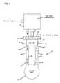
- FIGS. 1-2are perspective illustrations of an air system embodiment in accordance with the present invention.
- FIG. 3is a depiction of functional aspects of an air system according to the present invention, with arrows depicting air flow therethrough.
- FIG. 4is a side elevational view of a portion of a blade valve suitable for use with an embodiment of the present invention.
- FIG. 5is another side elevational view of a blade valve of FIG. 4 .
- FIG. 6is a top plan view of a rotationally balanced blade suitable for use within a rotary blade valve including within an embodiment of the present invention.
- FIG. 7is a cross sectional view of the blade of FIG. 6 , taken along lines 4 - 4 .
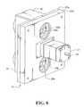
- FIGS. 8-13are perspective views of internal and external components of the apparatus of FIG. 1 .
- FIG. 14is a functional schematic of the system of FIG. 1 .
- FIG. 15is a perspective illustration of a mouthpiece device of FIG. 1 .
- FIG. 16is a top view of the mouthpiece of FIG. 15 .
- FIG. 17is a side view of the mouthpiece of FIG. 15 .
- FIG. 18is a cross sectional view of the mouthpiece taken along lines 5 - 5 in FIG. 16 .
- FIGS. 1-2illustrate perspective views of an exemplary embodiment of system 10 .
- system 10includes an air flow generator 12 providing intermittent pulses to a patient vest (not shown) during a therapy session.
- System 10additionally includes a pair of physiological data acquisition devices 6 , 8 adapted to be operatively coupled to a patient before, during or after a therapy session.
- sensor device 6is a pulse oximeter sensor and sensor device 8 is a mouthpiece through which the patient exhales in accordance with a lung function evaluation system as described herein.
- FIG. 3is a somewhat diagrammatical air flow diagram associated with system 10 .
- System 10includes an air flow generator component 12 , flowably connected to a pulse frequency control module 14 , which in turn is flowably connected to a pressure control device 16 , and finally to a vest 18 worn by the patient.
- the patientmay be a human or other animal.
- both human and equine applicationsmay be practicable, with differently sized vests 18 being defined by the particular applications.
- the air flow generatore.g., motor driven blower
- Air flow generator 12includes an electric blower, the speed of which may be fixed or variable depending on an application.
- System 10includes a blood oximeter for monitoring the blood oxygen saturation of the patient before, during or after a therapy session.
- the sensor accessory 6is attached to a blood-carrying tissue sample of the patient, such as the finger or ear lobe.
- sensor 6consist of a red LED, an infrared LED, and a single photodetector, but the sensor can include three or more LED's of different wavelengths and an associated plurality of photodetectors.
- the LED'sare driven by signals from a microprocessor, which may be the system 10 controller. Light from the LED's is transmitted through the tissue sample, and is detected by the photodetector, which produces an analog current signal with an amplitude proportional to the amount of light detected in each bandwidth.
- the current signal from the photodetectoris then digitized by the microprocessor.
- Ambient interference identification and elimination, and signal filteringcan be performed by means of digital signal processing software routines in the microprocessor.
- the microprocessorcalculates a ratio of a DC component representing the non-pulsating blood flow, and a AC component indicating the pulsatile blood flow.
- the microprocessordetermines the arterial oxygen saturation by comparing the result to the value stored in a look-up table or otherwise determined.
- a variety of blood oxygen sensors and controllersare suitably adaptable for use within system 10 .
- FIGS. 4-5illustrate pulse frequency control unit 14 .
- Unit 14includes a generally circular valve blade 20 , rotatable upon a central axis of motor 21 and having one or more cutout portions 22 .
- Blade 20is retained on a centrally located motor driven shaft 24 , which serves to rotate blade 20 , and in turn, provide airflow access to and through air ports 26 a and 26 b , respectively.
- Motor 21is coupled to motor shaft 24 and provides rotational control of blade 20 .
- Motor 21is a stepper motor providing accurate control of blade 20 position in order to define particular waveforms applied to vest 18 . As shown in corresponding FIG.
- a pair of plates 27 a and 27 bare mounted on an axis concentric with that of motor drive shaft 24 , and effectively sandwich the blade assembly between them.
- the end platesare provided with corresponding air ports 26 a and 26 b (in plate 27 a ) and 28 a and 28 b (in plate 27 b ).
- the air portsare overlapping such that air delivered from the external surface of either end plate will be free to exit the corresponding air port in the opposite plate, at such times as the blade cutout portion of the valve blade is itself in an overlapping position therebetween.
- the rotating fan bladeeffectively functions as a valve to permit air to pass into the corresponding air port in a semi-continuous and controllable fashion.
- the resultant deliverymay take a sinusoidal wave form, by virtue of the shape and arrangement of the fan blade cutout portions.
- Pulse frequency module 14in a preferred embodiment, is provided in the form of a motor-driven rotating blade 20 (“fan valve”) adapted to periodically interrupt the air stream from the air flow generator 12 . During these brief interruptions air pressure builds up behind the blade. When released, as by the passage of blade 20 , the air travels as a pressure pulse to vest 18 worn by the patient. The resulting pulses can be in the form of fast rise, sine wave pressure pulses. Alternative waveforms can be defined through accurate control of blade 20 , such as via an electronically controlled stepper motor. These pulses, in turn, can produce significantly faster air movement in the lungs, in the therapeutic frequency range of about 5 Hz to about 25 Hz, as measured at the mouth. In combination with higher flow rates into the lungs, as achieved using the present apparatus, these factors result in stronger mucus shear action, and thus more effective therapy in a shorter period of time.
- fan valvemotor-driven rotating blade 20
- Fan valve 20 of the present inventioncan be adapted (e.g., by configuring the dimensions, pitch, etc. of one or more fan blades) to provide wave pulses in a variety of forms, including sine waves, near sine waves (e.g., waves having precipitous rising and/or falling portions), and complex waves.
- a sine wavecan be generally defined as any uniform wave that is generated by a single frequency, and in particular, a wave whose amplitude is the sine of a linear function of time when plotted on a graph that plots amplitude against time.
- the pulsescan also include one or more relatively minor perturbations or fluctuations within and/or between individual waves, such that the overall wave form is substantially as described above.
- pulse frequency module 14 of the present inventioncan be programmed and controlled electronically to allow for the automatic timed cycling of frequencies, with the option of manual override at any frequency.
- blade 20includes hub 30 , a base plate element 31 and a variable thickness outer wall 32 .
- Outer wall 32is thinner in the region generally opposite cutout portion 22 and thicker proximate to the cutout portion 22 .
- the outer wall 32 thicknessis varied in order to statically and dynamically balance the blade 20 . By balancing blade 20 , a reduction in vibration and noise can be provided.
- pressure control unit 16defines a balancing chamber/manifold 50 in air communication with ports 26 a and 26 b of module 14 .
- Chamber 50is adapted to receive or pass air through ports 26 a and 26 b of pulse frequency control module 14 , and effectively provides a manifold or air chamber to deliver air to vest 18 or atmosphere by means of vest exit ports 51 , 52 and atmosphere exit port 53 .
- air manifold 50 of pressure control unit 16defines a fluid communicating bypass between ports 51 and 52 , and hence fluid communication between the ports of pulse frequency control module 14 and air lines 60 to patient vest 18 .
- air chamber 50receives HFCC pulse pressure waves through ports 26 a , 28 a .
- Port 53is connected to port 28 b of frequency control module 14 and is closed to atmosphere when 26 a is open and open when 26 a is closed.
- Ports 51 and 52are connected to the inflatable vest 18 via flexible tubing 60 .
- Pulse pressure control 16is located between frequency control module 14 and vest 18 worn by the patient.
- air chamber 50 of pulse pressure control 16is immediately adjacent pulse frequency control module 14 .
- a structure defining the air chamberis directly connected to the outlet ports of the pulse frequency control module 14 .
- the manifold or air chamber 50provides fluid communication between air lines 60 extending to vest 18 and the bladder-side ports of the pulse frequency control module 14 .
- Pressure control unit 16may be active or passive.
- an active pressure control unitmay include, for example, valves and electric solenoids in communication with an electronic controller, microprocessor, etc.
- a passive pressure control unit 16may include a manual pressure relief or, in a simple embodiment, pressure control unit 16 may include only the air chamber providing air communication between the air lines extending to the vest 18 and not otherwise including a pressure relief or variable pressure control.
- FIGS. 10-13illustrate external and internal aspects of system 10 .
- System 10includes shell or housing 70 having front portion 71 and top portion 72 .
- Front portion 71includes a user interface including display 73 .
- System 10defines air openings 74 , electrical connection 75 , telecom connections 76 , and power switch 77 .
- User interfaceincludes a visual display 73 which allows the patient to control device 10 .
- Air openings 74permit air entry into system 10 .
- a removable filter 79is adapted to be periodically removed and cleaned to minimize debris entry into system 10 .
- System 10further includes a plurality of quick connect air couplings 80 , 82 which couple vest 18 with system 10 via air hoses 60 .
- Each quick connect air coupling 80 , 82includes male and female portions and a latch or other release for quickly disconnecting the portions.
- the benefits of the quick connect air couplingsinclude minimization of inadvertent air hose disconnects and improved freedom of movement as the locking air coupling permit rotation between the air hose and the vest or air generator.
- plenum 90is defined between an inlet port of air flow generator 12 and external housing 70 .
- Plenum 90defines an air conduit between for air entering system 10 .
- Plenum 90includes a pair of openings, one positioned near opening 74 and the other positioned at an inlet to the electric blower motor of air flow generator 12 .
- Plenum 90is provided with a generally decreasing cross sectional volume as it extends from air opening 74 towards the inlet of air flow generator 12 .
- Plenum 90promotes a reduction in sound generation as air is more efficiently drawn into generator 12 as compared to an open fan inlet.
- Tubular couplings 91provide fluid communication to air flow generator 12 to control devices 14 , 16 and quick connect air couplings 80 , 82 .
- FIG. 14illustrates a somewhat diagrammatical schematic of system 10 .
- Controller 160is connected to modem interface 76 permitting communication to and from system 10 to a remote location. Examples of communication include monitoring of system 10 performance, updating software used by controller 160 monitoring patient compliance, performing remote system diagnostics, etc.
- Controller 160provides control of stepper motor 21 providing rotational control to fan 20 .
- Controller 160in this embodiment, in communication with the pulse oximeter system and the lung function mouthpiece sensor. With sensor input from the oximeter and/or mouthpiece, controller 160 may adjust one or more operational parameters of system 10 . For example, controller 160 may change the speed of motor 21 as a function of patient airway as indicated by the mouthpiece data. In another example, controller 160 may adjust the output of air flow generator 12 based on a lung function trend analysis using mouthpiece 8
- System 10 activation/deactivationis controlled through on/off switch 77 .
- the user interfaceincludes touch-sensitive display panel 73 .
- Display panel 73is preferably an LCD panel display, although other displays could also be used.
- Display panel 73shows the status of system 10 and options available for usage, optimization and/or modification of system 10 .
- System 10also provides a variety of feed back to the patient as to system status, blood oxygen saturation, lung function trending, etc.
- the display 73may be utilized to coordinate usage of the pulse oximeter and mouthpiece sensor 8 during therapy sessions.
- Datamay be collected by the system 10 relating to system use, operation, errors, status, patient compliance and a variety of patient physiological data. Data may be transferred from system 10 to a remote system via various wired or wireless means, including but not limited to BLUETOOTH transmissions and removable memory appliances. Data across multiple systems may be utilized in outcome assessments.
- update informationmay be stored on a removable memory appliance and transferred to system 10 or transmitted wirelessly directly to system 10 from a remote source.
- the updated informationmay include operating software, software updates, etc.
- a removable memory appliancemay be used to transmit data both to/from a remote system, the data including patient and system data and update information.
- FIGS. 15-18illustrate various view of physiological sensor accessory 8 adapted for use with a congestion monitor of system 10 .
- Sensor 8is a mouthpiece through which a patient exhales.
- Sensor 8defines an open ended tube having an interior flow restriction 166 and a pair of air ports 168 , 169 .
- the mouthpiece sensor 8may be generally cylindrical in form, as shown, or may assume alternative shapes.
- the flow restriction 166may be a ring form, as shown, or may assume alternative configurations.
- the flow restriction 166may be generally centered along the length of the mouthpiece tube or may be offset relative to center. It is envisioned that a variety of different mouthpiece configurations could be utilized in alternative designs suitable for use within system 10 .
- Mouthpiece sensor 8is connected to system 10 via a pair of flexible tubes 170 , 172 .
- Tubes 170 , 172engage the airports 168 , 169 of mouthpiece sensor 8 at one end and are coupled to air ports of system 10 via threaded couplings 178 at the other end (as shown in FIG. 2 ).
- System 10includes a differential air pressure sensor (not shown) in communication with the controller of system 10 .
- the patientmay be prompted to use mouthpiece sensor 8 by a visual and/or auditory cue provided by system 10 .
- a variety of visual displaysmay illustrate to the patient the correct manner of use, via for example a video displayed on panel 73 .
- the visual displaymay also facilitate proper use of the mouthpiece accessory by indicating proper airflow and providing an alarm when, for example, the airflow is insufficient to provide an accurate reading or the airflow is reversed.
- Various entertainment programscould be utilized via display 73 to encourage routine use of the mouthpiece sensor by the patient.
- system 10may implement an age-appropriate game on display 73 promoting increased compliance by a pediatric patient.
- a variety of such gamesare envisioned with data from one or more physiological data sensors providing real-time user input for the games.
- system 10may include a CO 2 or other gas monitor to evaluate patient condition.
- a CO 2 monitorcould be provided as a small gas sampler within the housing of system 10 .
- System 10includes a congestion monitor designed to measure total volume of air expired in the first one second of a forced expiratory breath. This value when monitored on a regular basis can be a valuable tool in managing chronic obstructive pulmonary disease. It is often difficult for a patient to determine the gradual trending direction of his or her lung function without pulmonary testing over time. Using the congestion monitor on a regular basis can indicate to the patient whether his or her lung function is stable, decreasing, or improving. It gives the patient the opportunity to better judge the right combination of therapy, whether or not to increase therapy, and/or to contact his or her doctor.
- the congestion monitorwas designed to measure, with consistency, a one second volume of air flow. This measurement is repeatable to within plus or minus 3 percent over a range of 0 to 12 liters per second. The consistency of measurement allows the patient to establish a base line measurement that can be used to show trending of lung congestion over time. It is not a measure of true FEV1 values and should not be compared to FEV1 values measured in a pulmonary function laboratory. Additional disclosure relating to the mouthpiece and airway congestion monitoring system are disclosed in applicant's US Provisional Patent Application, Mouthpiece and Airway Congestion Monitoring System, Ser. No. 61/161,707, incorporated by reference herein.
- HFCC therapyis prescribed as either an adjunct or outright replacement for manual chest physiotherapy.
- Total therapy time per dayvaries between about 30 minutes and about 240 minutes spread over one to four treatments per day.
- Patientscan be instructed in either the continuous intermittent mode of HFCC therapy, which may include continuous use of aerosol.
- Air flow generator module 12is provided in the form of a single stage compressor, and is enclosed in a compartment having air inlet and outlet ports.
- the air inlet portcan be open to atmosphere, while the outlet port can be flowably coupled to the pulse frequency control module.
- the air flow generator module 12may include a variable speed air fan adapted to be used with an electronic motor speed controller.
- the amplitude of pulses transmitted to the air vest 18may be controlled by adjusting the fan motor speed.
- the amplitude of the pulsesmay be increased or decreased in response to received physiological signals providing patient information, such as inhalation and exhalation periods, etc.
- System 10can provide pressurized pulses of on the order of 60 mm Hg or less.
- the ability to provide pulses having higher pressure, while also minimizing the overall size and weight of the unit,is a particular advantage of the present apparatus as well. Pulses of over about 60 mm Hg are generally not desirable, since they can tend to lead to bruising.
- System 10may include one or more display screens allowing the caregiver to control the operation of any of the additional respiratory therapy system(s) and/or assessment system(s) included in system 10 .
- the set of operating parametersmay be stored in the on-board memory associated with the controller or microprocessor.
- the system housinghas two large air ports which are configured to be coupled to a HFCC therapy garment via hoses.
- the garmenthas at least one bladder and is configured to be positioned on a patient receiving HFCC therapy.
- An example of a garment suitable for use with the systemis disclosed in U.S. Ser. No. 12/106,836, which is hereby incorporated by reference herein.
- the controllerIn response to user inputs, the controller signals air pulse generator to deliver high frequency air pulses to the patient in accordance with a set of operating parameters.
- system 10may also be couplable to a nebulizer mouthpiece (not shown).
- a mask and/or nebulizer mouthpiececan be used when the system performs one or more of the integrated additional therapies such as, for example, nebulizer therapy and cough assist therapy.
- the controller of system 10signals the air pulse generator to deliver high frequency air pulses to a patient in accordance with the portion of the set of operating parameters stored in a memory device.
- the memory deviceis configured to store one or more of a plurality of pre-programmed therapy modes to allow a caregiver to deliver HFCC therapy to a patient in accordance with any one of the plurality of pre-programmed therapy modes stored in the memory device.
- the pre-programmed therapy modesinclude a step program mode, a sweep program mode, a training program mode, and the like.
- the step and sweep program modesare substantially as described in U.S. Ser. No. 11/520,846, which is already incorporated by reference herein.
- a program modeallows the caregiver to start at a desired starting frequency and/or intensity for the HFCC therapy and automatically gradually increase the frequency and/or intensity over a predetermined period of time or a programmed period of time to a desired maximum frequency and intensity.
- System 10may include a memory device configured to store one or more of a plurality of customized therapy modes to allow a caregiver to deliver HFCC therapy to a patient in accordance with any one of the plurality of customized therapy modes stored in the memory device.
- the caregiveris able to create a special waveform for a particular patient's therapy.
- Such a special waveformmay be in accordance with wave type, frequency, pressure, and timing parameters of the caregiver's choosing or may be in accordance with a menu of special waveforms preprogrammed into the system.
- a memory deviceis configured to store information regarding functionalities available to a patient.
- Examples of functionalities available to a patientinclude one or more of a positive expiratory pressure (PEP) therapy, a nebulizer therapy, an intermittent positive pressure breathing (IPPB) therapy, a cough assist therapy, a suction therapy, a bronchial dilator therapy, and the like.
- PEPpositive expiratory pressure
- IPPBintermittent positive pressure breathing
Landscapes
- Health & Medical Sciences (AREA)
- Cardiology (AREA)
- Heart & Thoracic Surgery (AREA)
- Emergency Medicine (AREA)
- Pulmonology (AREA)
- Epidemiology (AREA)
- Pain & Pain Management (AREA)
- Physical Education & Sports Medicine (AREA)
- Rehabilitation Therapy (AREA)
- Life Sciences & Earth Sciences (AREA)
- Animal Behavior & Ethology (AREA)
- General Health & Medical Sciences (AREA)
- Public Health (AREA)
- Veterinary Medicine (AREA)
- Measurement Of The Respiration, Hearing Ability, Form, And Blood Characteristics Of Living Organisms (AREA)
Abstract
Description
Claims (25)
Priority Applications (1)
| Application Number | Priority Date | Filing Date | Title |
|---|---|---|---|
| US12/482,219US8257288B2 (en) | 2000-06-29 | 2009-06-10 | Chest compression apparatus having physiological sensor accessory |
Applications Claiming Priority (6)
| Application Number | Priority Date | Filing Date | Title |
|---|---|---|---|
| PCT/US2000/018037WO2001001918A1 (en) | 1999-07-02 | 2000-06-29 | Chest compression apparatus |
| US10/038,208US6958046B2 (en) | 1998-05-07 | 2002-01-02 | Chest compression apparatus |
| US11/204,547US7597670B2 (en) | 1999-07-02 | 2005-08-15 | Chest compression apparatus |
| US11/520,846US7762967B2 (en) | 1999-07-02 | 2006-09-12 | Chest compression apparatus |
| US6037908P | 2008-06-10 | 2008-06-10 | |
| US12/482,219US8257288B2 (en) | 2000-06-29 | 2009-06-10 | Chest compression apparatus having physiological sensor accessory |
Related Parent Applications (1)
| Application Number | Title | Priority Date | Filing Date |
|---|---|---|---|
| US11/520,846Continuation-In-PartUS7762967B2 (en) | 1999-07-02 | 2006-09-12 | Chest compression apparatus |
Publications (2)
| Publication Number | Publication Date |
|---|---|
| US20090306556A1 US20090306556A1 (en) | 2009-12-10 |
| US8257288B2true US8257288B2 (en) | 2012-09-04 |
Family
ID=41404349
Family Applications (1)
| Application Number | Title | Priority Date | Filing Date |
|---|---|---|---|
| US12/482,219Active2031-05-30US8257288B2 (en) | 2000-06-29 | 2009-06-10 | Chest compression apparatus having physiological sensor accessory |
Country Status (1)
| Country | Link |
|---|---|
| US (1) | US8257288B2 (en) |
Cited By (8)
| Publication number | Priority date | Publication date | Assignee | Title |
|---|---|---|---|---|
| US9549869B2 (en) | 2012-06-29 | 2017-01-24 | Hill-Rom Canado Respiratory Ltd. | Wearable thorax percussion device |
| US9744097B2 (en) | 2012-06-29 | 2017-08-29 | Hill-Rom Services Pte. Ltd. | Wearable thorax percussion device |
| US20180289174A1 (en)* | 2017-04-10 | 2018-10-11 | Hill-Rom Services, Inc. | Mattress overlay for p&v, turn assist and mcm |
| US11432991B2 (en) | 2016-05-11 | 2022-09-06 | Koninklijke Philips N.V. | Chest wall oscillation system with digital auscultation |
| US11471366B2 (en) | 2016-08-22 | 2022-10-18 | Hill-Rom Services Pte. Ltd. | Percussion therapy apparatus and methods thereof |
| US11944582B2 (en) | 2013-04-30 | 2024-04-02 | Zoll Medical Corporation | Compression depth monitor with variable release velocity feedback |
| US12303455B2 (en) | 2020-08-03 | 2025-05-20 | Hill-Rom Services, Inc. | Therapeutic technique using electrical impedance spectroscopy |
| USD1089626S1 (en) | 2022-04-19 | 2025-08-19 | Hill-Rom Services Pte. Ltd. | Air pulse generator housing |
Families Citing this family (6)
| Publication number | Priority date | Publication date | Assignee | Title |
|---|---|---|---|---|
| JP5785543B2 (en)* | 2009-07-24 | 2015-09-30 | コーニンクレッカ フィリップス エヌ ヴェ | Device and method for assisting cough |
| US9949892B2 (en) | 2013-10-11 | 2018-04-24 | Peking Union Medical College Hospital | Pulse oximetry-based cardio-pulmonary resuscitation (CPR) quality feedback systems and methods |
| CN107041838B (en)* | 2013-10-11 | 2020-09-08 | 中国医学科学院北京协和医院 | Cardio-pulmonary resuscitation quality feedback control system based on pulse blood oxygen |
| EP3439609B1 (en) | 2016-04-04 | 2020-12-30 | Respiratory Technologies, Inc. | Chest compression devices and systems |
| US20210052461A1 (en)* | 2019-08-20 | 2021-02-25 | Hill-Rom Services Pte. Ltd. | Disease-based configurations in a high-frequency chest wall oscillation device |
| AU2020382453A1 (en)* | 2019-11-11 | 2022-06-30 | Hill-Rom Services Pte. Ltd. | Adaptive high frequency chest wall oscillation system |
Citations (39)
| Publication number | Priority date | Publication date | Assignee | Title |
|---|---|---|---|---|
| US2588192A (en) | 1947-02-01 | 1952-03-04 | Akerman | Artificial respiration apparatus |
| US3462778A (en) | 1966-02-25 | 1969-08-26 | Gaymar Ind Inc | Inflatable mattress and pressure system |
| US4135500A (en) | 1977-04-28 | 1979-01-23 | Medpro, Inc. | Apparatus for oscillating flotation support systems |
| US4197837A (en) | 1977-10-04 | 1980-04-15 | American Hospital Supply Corporation | Inflatable-deflatable pad and air control system therefor |
| US4311135A (en) | 1979-10-29 | 1982-01-19 | Brueckner Gerald G | Apparatus to assist leg venous and skin circulation |
| US4519146A (en) | 1983-06-24 | 1985-05-28 | Mobil Oil Corporation | Air ring plenum with molded housing |
| US4653498A (en) | 1982-09-13 | 1987-03-31 | Nellcor Incorporated | Pulse oximeter monitor |
| US4838263A (en) | 1987-05-01 | 1989-06-13 | Regents Of The University Of Minnesota | Chest compression apparatus |
| US4977889A (en) | 1989-10-12 | 1990-12-18 | Regents Of The University Of Minnesota | Fitting and tuning chest compression device |
| US5056505A (en) | 1987-05-01 | 1991-10-15 | Regents Of The University Of Minnesota | Chest compression apparatus |
| US5453081A (en) | 1993-07-12 | 1995-09-26 | Hansen; Craig N. | Pulsator |
| WO1995032753A1 (en) | 1994-06-01 | 1995-12-07 | Dranez Anstalt | Ventilator apparatus |
| US5490820A (en) | 1993-03-12 | 1996-02-13 | Datascope Investment Corp. | Active compression/decompression cardiac assist/support device and method |
| US5569170A (en) | 1993-07-12 | 1996-10-29 | Electromed, Inc. | Pulsator |
| US5769800A (en) | 1995-03-15 | 1998-06-23 | The Johns Hopkins University Inc. | Vest design for a cardiopulmonary resuscitation system |
| US5769797A (en) | 1996-06-11 | 1998-06-23 | American Biosystems, Inc. | Oscillatory chest compression device |
| US5997488A (en) | 1996-10-09 | 1999-12-07 | Cardiologic Systems, Inc. | Cardiopulmonary resuscitation system with centrifugal compression pump |
| US6030353A (en) | 1998-04-28 | 2000-02-29 | American Biosystems, Inc. | Pneumatic chest compression apparatus |
| US6155996A (en) | 1998-06-30 | 2000-12-05 | American Biosystems, Inc. | Disposable pneumatic chest compression vest |
| US6179796B1 (en) | 1997-04-11 | 2001-01-30 | Tactile Systems, Inc. | Lymphedema treatment system |
| US6182658B1 (en) | 1995-10-31 | 2001-02-06 | Zamir Hayek | Fluid control valves |
| US6210345B1 (en) | 1999-10-04 | 2001-04-03 | American Biosystems, Inc. | Outcome measuring airway resistance diagnostic system |
| US6254556B1 (en) | 1998-03-12 | 2001-07-03 | Craig N. Hansen | Repetitive pressure pulse jacket |
| US20020014235A1 (en) | 2000-04-28 | 2002-02-07 | Rogers Peter H. | Apparatus and method for implementing hydro-acoustic therapy for the lungs |
| USD453560S1 (en) | 2000-05-08 | 2002-02-12 | American Biosystems, Inc. | Air flow generator |
| US6379316B1 (en) | 1999-08-31 | 2002-04-30 | Advanced Respiratory, Inc. | Method and apparatus for inducing sputum samples for diagnostic evaluation |
| USD456591S1 (en) | 2000-05-05 | 2002-05-07 | Craig N. Hansen | Human body pulsating jacket |
| US20020111571A1 (en) | 1998-05-07 | 2002-08-15 | Warwick Warren J. | Chest compression apparatus |
| USD461897S1 (en) | 2001-07-02 | 2002-08-20 | Electromed, Inc. | Human body respiratory vest |
| US6471663B1 (en) | 1999-08-31 | 2002-10-29 | American Biosystems, Inc. | Chest compression vest with connecting belt |
| USD469876S1 (en) | 2001-07-03 | 2003-02-04 | Electromed, Inc. | Human respiratory bladder |
| US6547749B2 (en) | 2000-07-13 | 2003-04-15 | Electromed, Inc. | Body pulsating method and apparatus |
| USD478989S1 (en) | 2002-04-08 | 2003-08-26 | Electromed, Inc. | Supine respiratory vest |
| US6676614B1 (en) | 2000-07-11 | 2004-01-13 | Electromed, Inc. | Vest for body pulsating method and apparatus |
| US6733464B2 (en) | 2002-08-23 | 2004-05-11 | Hewlett-Packard Development Company, L.P. | Multi-function sensor device and methods for its use |
| US6736785B1 (en) | 1999-08-09 | 2004-05-18 | Advanced Respiratory, Inc. | Mechanical chest wall oscillator |
| US6757916B2 (en) | 2002-08-28 | 2004-07-06 | Mustang Survival Corp. | Pressure applying garment |
| US6916298B2 (en) | 1999-08-31 | 2005-07-12 | Advanced Respiratory, Inc. | Pneumatic chest compression vest with front panel air bladder |
| US20060009718A1 (en) | 2002-11-15 | 2006-01-12 | Van Brunt Nicholas P | Air pulse generator with multiple operating modes |
- 2009
- 2009-06-10USUS12/482,219patent/US8257288B2/enactiveActive
Patent Citations (48)
| Publication number | Priority date | Publication date | Assignee | Title |
|---|---|---|---|---|
| US2588192A (en) | 1947-02-01 | 1952-03-04 | Akerman | Artificial respiration apparatus |
| US3462778A (en) | 1966-02-25 | 1969-08-26 | Gaymar Ind Inc | Inflatable mattress and pressure system |
| US4135500A (en) | 1977-04-28 | 1979-01-23 | Medpro, Inc. | Apparatus for oscillating flotation support systems |
| US4197837A (en) | 1977-10-04 | 1980-04-15 | American Hospital Supply Corporation | Inflatable-deflatable pad and air control system therefor |
| US4311135A (en) | 1979-10-29 | 1982-01-19 | Brueckner Gerald G | Apparatus to assist leg venous and skin circulation |
| US4653498A (en) | 1982-09-13 | 1987-03-31 | Nellcor Incorporated | Pulse oximeter monitor |
| US4653498B1 (en) | 1982-09-13 | 1989-04-18 | ||
| US4519146A (en) | 1983-06-24 | 1985-05-28 | Mobil Oil Corporation | Air ring plenum with molded housing |
| US5056505A (en) | 1987-05-01 | 1991-10-15 | Regents Of The University Of Minnesota | Chest compression apparatus |
| US4838263A (en) | 1987-05-01 | 1989-06-13 | Regents Of The University Of Minnesota | Chest compression apparatus |
| US4977889A (en) | 1989-10-12 | 1990-12-18 | Regents Of The University Of Minnesota | Fitting and tuning chest compression device |
| US5490820A (en) | 1993-03-12 | 1996-02-13 | Datascope Investment Corp. | Active compression/decompression cardiac assist/support device and method |
| US5453081A (en) | 1993-07-12 | 1995-09-26 | Hansen; Craig N. | Pulsator |
| US5569170A (en) | 1993-07-12 | 1996-10-29 | Electromed, Inc. | Pulsator |
| WO1995032753A1 (en) | 1994-06-01 | 1995-12-07 | Dranez Anstalt | Ventilator apparatus |
| US5769800A (en) | 1995-03-15 | 1998-06-23 | The Johns Hopkins University Inc. | Vest design for a cardiopulmonary resuscitation system |
| US6182658B1 (en) | 1995-10-31 | 2001-02-06 | Zamir Hayek | Fluid control valves |
| US5769797A (en) | 1996-06-11 | 1998-06-23 | American Biosystems, Inc. | Oscillatory chest compression device |
| US6036662A (en) | 1996-06-11 | 2000-03-14 | American Biosystems, Inc. | Oscillatory chest compression device |
| US5997488A (en) | 1996-10-09 | 1999-12-07 | Cardiologic Systems, Inc. | Cardiopulmonary resuscitation system with centrifugal compression pump |
| US6179796B1 (en) | 1997-04-11 | 2001-01-30 | Tactile Systems, Inc. | Lymphedema treatment system |
| US6254556B1 (en) | 1998-03-12 | 2001-07-03 | Craig N. Hansen | Repetitive pressure pulse jacket |
| US6605050B2 (en) | 1998-03-12 | 2003-08-12 | Electromed, Inc. | Body pulsating jacket |
| US6488641B2 (en) | 1998-03-12 | 2002-12-03 | Electromed, Inc. | Body pulsating apparatus |
| US6030353A (en) | 1998-04-28 | 2000-02-29 | American Biosystems, Inc. | Pneumatic chest compression apparatus |
| US20020111571A1 (en) | 1998-05-07 | 2002-08-15 | Warwick Warren J. | Chest compression apparatus |
| US6958046B2 (en) | 1998-05-07 | 2005-10-25 | Warwick Warren J | Chest compression apparatus |
| US6155996A (en) | 1998-06-30 | 2000-12-05 | American Biosystems, Inc. | Disposable pneumatic chest compression vest |
| US6736785B1 (en) | 1999-08-09 | 2004-05-18 | Advanced Respiratory, Inc. | Mechanical chest wall oscillator |
| US6379316B1 (en) | 1999-08-31 | 2002-04-30 | Advanced Respiratory, Inc. | Method and apparatus for inducing sputum samples for diagnostic evaluation |
| US6764455B2 (en) | 1999-08-31 | 2004-07-20 | Advanced Respiratory, Inc. | Chest compression vest with connecting belt |
| US6471663B1 (en) | 1999-08-31 | 2002-10-29 | American Biosystems, Inc. | Chest compression vest with connecting belt |
| US6916298B2 (en) | 1999-08-31 | 2005-07-12 | Advanced Respiratory, Inc. | Pneumatic chest compression vest with front panel air bladder |
| US6210345B1 (en) | 1999-10-04 | 2001-04-03 | American Biosystems, Inc. | Outcome measuring airway resistance diagnostic system |
| US6340025B1 (en) | 1999-10-04 | 2002-01-22 | American Biosystems, Inc. | Airway treatment apparatus with airflow enhancement |
| US6415791B1 (en) | 1999-10-04 | 2002-07-09 | American Biosystems, Inc. | Airway treatment apparatus with cough inducement |
| US6910479B1 (en) | 1999-10-04 | 2005-06-28 | Advanced Respiratory, Inc. | Airway treatment apparatus with bias line cancellation |
| US20020014235A1 (en) | 2000-04-28 | 2002-02-07 | Rogers Peter H. | Apparatus and method for implementing hydro-acoustic therapy for the lungs |
| USD456591S1 (en) | 2000-05-05 | 2002-05-07 | Craig N. Hansen | Human body pulsating jacket |
| USD453560S1 (en) | 2000-05-08 | 2002-02-12 | American Biosystems, Inc. | Air flow generator |
| US6676614B1 (en) | 2000-07-11 | 2004-01-13 | Electromed, Inc. | Vest for body pulsating method and apparatus |
| US6547749B2 (en) | 2000-07-13 | 2003-04-15 | Electromed, Inc. | Body pulsating method and apparatus |
| USD461897S1 (en) | 2001-07-02 | 2002-08-20 | Electromed, Inc. | Human body respiratory vest |
| USD469876S1 (en) | 2001-07-03 | 2003-02-04 | Electromed, Inc. | Human respiratory bladder |
| USD478989S1 (en) | 2002-04-08 | 2003-08-26 | Electromed, Inc. | Supine respiratory vest |
| US6733464B2 (en) | 2002-08-23 | 2004-05-11 | Hewlett-Packard Development Company, L.P. | Multi-function sensor device and methods for its use |
| US6757916B2 (en) | 2002-08-28 | 2004-07-06 | Mustang Survival Corp. | Pressure applying garment |
| US20060009718A1 (en) | 2002-11-15 | 2006-01-12 | Van Brunt Nicholas P | Air pulse generator with multiple operating modes |
Non-Patent Citations (4)
| Title |
|---|
| International Preliminary Report on Patentability, PCT/US2006/034783, Mar. 27, 2008. |
| International Search Report and Written Opinion, PCT/US2006/034783, Apr. 18, 2007. |
| Milla, Carlos E. et al., "High-Frequency Chest Compression: Effect of the Third Generation Compression Waveform", Instrument Research, Jul./Aug. 2004, 322-328. |
| PCT Written Opinion and Search Report, mailed Jan. 27, 2010. |
Cited By (13)
| Publication number | Priority date | Publication date | Assignee | Title |
|---|---|---|---|---|
| US10980695B2 (en) | 2012-06-29 | 2021-04-20 | Hill-Rom Services Pte. Ltd. | Method of making a wearable thorax percussion device |
| US9744097B2 (en) | 2012-06-29 | 2017-08-29 | Hill-Rom Services Pte. Ltd. | Wearable thorax percussion device |
| US10292890B2 (en) | 2012-06-29 | 2019-05-21 | Hill-Rom Services Pte. Ltd. | Wearable thorax percussion device |
| US9549869B2 (en) | 2012-06-29 | 2017-01-24 | Hill-Rom Canado Respiratory Ltd. | Wearable thorax percussion device |
| US11944582B2 (en) | 2013-04-30 | 2024-04-02 | Zoll Medical Corporation | Compression depth monitor with variable release velocity feedback |
| US11432991B2 (en) | 2016-05-11 | 2022-09-06 | Koninklijke Philips N.V. | Chest wall oscillation system with digital auscultation |
| US11471366B2 (en) | 2016-08-22 | 2022-10-18 | Hill-Rom Services Pte. Ltd. | Percussion therapy apparatus and methods thereof |
| US20180289174A1 (en)* | 2017-04-10 | 2018-10-11 | Hill-Rom Services, Inc. | Mattress overlay for p&v, turn assist and mcm |
| US10856668B2 (en)* | 2017-04-10 | 2020-12-08 | Hill-Rom Services, Inc. | Mattress overlay control system with rotary valves and graphical user interface for percussion and vibration, turn assist and microclimate management |
| US20210052084A1 (en)* | 2017-04-10 | 2021-02-25 | Hill-Rom Services, Inc. | Rotary plate valve having seal anti-herniation structure |
| US11684169B2 (en)* | 2017-04-10 | 2023-06-27 | Hill-Rom Services, Inc. | Rotary plate valve having seal anti-herniation structure |
| US12303455B2 (en) | 2020-08-03 | 2025-05-20 | Hill-Rom Services, Inc. | Therapeutic technique using electrical impedance spectroscopy |
| USD1089626S1 (en) | 2022-04-19 | 2025-08-19 | Hill-Rom Services Pte. Ltd. | Air pulse generator housing |
Also Published As
| Publication number | Publication date |
|---|---|
| US20090306556A1 (en) | 2009-12-10 |
Similar Documents
| Publication | Publication Date | Title |
|---|---|---|
| US8257288B2 (en) | Chest compression apparatus having physiological sensor accessory | |
| CN1330392C (en) | Dual-pressure air supply unit for positive air pressure therapy devices | |
| US7762967B2 (en) | Chest compression apparatus | |
| US8192381B2 (en) | Air vest for chest compression apparatus | |
| EP1897576B1 (en) | Portable breathing device | |
| EP1897597B1 (en) | Randomly interrupted breathing device | |
| EP2316514B1 (en) | Composite lung therapy device | |
| US20110125068A1 (en) | Frequency Optimization for Chest Compression Apparatus | |
| AU2001235258A1 (en) | Dual-pressure blower for positive air pressure device | |
| JP7738938B2 (en) | Artificial ventilation devices | |
| EP3737475A1 (en) | Respiratory training and airway pressure monitoring device | |
| US20160151232A1 (en) | Hfcc therapy system providing device adherence data | |
| WO2014030099A1 (en) | Synchronizing mechanical in-exsufflation and diaphragmatic pacing | |
| WO2017176745A1 (en) | Chest compression devices, systems, and methods | |
| WO2010033429A1 (en) | Warming therapy device including resuscitation control system | |
| AU2022412071A1 (en) | Measurement device and system for breathing assistance apparatus and/or performing diagnostics | |
| US7597670B2 (en) | Chest compression apparatus | |
| WO2009152252A2 (en) | Chest compression apparatus having physiological sensor accessory | |
| WO2020170108A1 (en) | A medical device for the exercise of a user's respiratory functions and non-therapeutic monitoring and data collection method | |
| WO2007033304A2 (en) | Chest compression apparatus | |
| KR102853447B1 (en) | A Breathing Device that Provides Real-Time Feedback to Strengthen Respiratory Muscles | |
| EP1397994B1 (en) | Apparatus for measuring the strength of a person's respiratory muscles | |
| US20250295873A1 (en) | Device for unblocking and removing secretions from airways | |
| CN120771522A (en) | Postoperative care guardianship respiratory training ware | |
| WO2024261699A1 (en) | Respiratory system for facilitating respiratory physiotherapy |
Legal Events
| Date | Code | Title | Description |
|---|---|---|---|
| AS | Assignment | Owner name:RESPIRTECH, MINNESOTA Free format text:ASSIGNMENT OF ASSIGNORS INTEREST;ASSIGNORS:HANSEN, LELAND G.;WHITE, GREG;REEL/FRAME:025734/0282 Effective date:20110127 | |
| AS | Assignment | Owner name:MEDALLION CAPITAL, INC., MINNESOTA Free format text:SECURITY AGREEMENT;ASSIGNOR:RESPIRATORY TECHNOLOGIES, INC.;REEL/FRAME:028127/0298 Effective date:20120425 | |
| STCF | Information on status: patent grant | Free format text:PATENTED CASE | |
| FPAY | Fee payment | Year of fee payment:4 | |
| AS | Assignment | Owner name:RESPIRATORY TECHNOLOGIES, INC., MINNESOTA Free format text:ASSIGNMENT OF ASSIGNORS INTEREST;ASSIGNOR:RESPIRTECH;REEL/FRAME:040603/0650 Effective date:20161208 | |
| AS | Assignment | Owner name:RESPIRATORY TECHNOLOGIES, INC., MINNESOTA Free format text:RELEASE OF SECURITY INTEREST, RELEASING THE SECURITY INTEREST PREVIOUSLY RECORDED AT REEL 028127 AND FRAME 0298;ASSIGNOR:MEDALLION CAPITAL, INC.;REEL/FRAME:043565/0299 Effective date:20170814 | |
| FEPP | Fee payment procedure | Free format text:ENTITY STATUS SET TO UNDISCOUNTED (ORIGINAL EVENT CODE: BIG.) | |
| FEPP | Fee payment procedure | Free format text:7.5 YR SURCHARGE - LATE PMT W/IN 6 MO, LARGE ENTITY (ORIGINAL EVENT CODE: M1555); ENTITY STATUS OF PATENT OWNER: LARGE ENTITY | |
| MAFP | Maintenance fee payment | Free format text:PAYMENT OF MAINTENANCE FEE, 8TH YEAR, LARGE ENTITY (ORIGINAL EVENT CODE: M1552); ENTITY STATUS OF PATENT OWNER: LARGE ENTITY Year of fee payment:8 | |
| MAFP | Maintenance fee payment | Free format text:PAYMENT OF MAINTENANCE FEE, 12TH YEAR, LARGE ENTITY (ORIGINAL EVENT CODE: M1553); ENTITY STATUS OF PATENT OWNER: LARGE ENTITY Year of fee payment:12 |