US8257287B2 - Safety connector assembly - Google Patents
Safety connector assemblyDownload PDFInfo
- Publication number
- US8257287B2 US8257287B2US12/052,282US5228208AUS8257287B2US 8257287 B2US8257287 B2US 8257287B2US 5228208 AUS5228208 AUS 5228208AUS 8257287 B2US8257287 B2US 8257287B2
- Authority
- US
- United States
- Prior art keywords
- connector
- conduit
- sealing surface
- connector assembly
- fluid
- Prior art date
- Legal status (The legal status is an assumption and is not a legal conclusion. Google has not performed a legal analysis and makes no representation as to the accuracy of the status listed.)
- Active, expires
Links
- 239000012530fluidSubstances0.000claimsabstractdescription43
- 238000007789sealingMethods0.000claimsdescription163
- 230000008878couplingEffects0.000claimsdescription61
- 238000010168coupling processMethods0.000claimsdescription61
- 238000005859coupling reactionMethods0.000claimsdescription61
- 239000000463materialSubstances0.000claimsdescription11
- 206010070995Vascular compressionDiseases0.000claimsdescription3
- 238000004891communicationMethods0.000claimsdescription3
- 230000006835compressionEffects0.000abstractdescription24
- 238000007906compressionMethods0.000abstractdescription24
- 238000002560therapeutic procedureMethods0.000abstractdescription20
- 230000013011matingEffects0.000abstractdescription7
- 206010051055Deep vein thrombosisDiseases0.000abstractdescription3
- 206010047249Venous thrombosisDiseases0.000abstractdescription3
- 239000002904solventSubstances0.000description4
- 238000003466weldingMethods0.000description4
- 230000015572biosynthetic processEffects0.000description3
- 238000001990intravenous administrationMethods0.000description3
- 238000004519manufacturing processMethods0.000description3
- 230000037361pathwayEffects0.000description3
- 238000005452bendingMethods0.000description2
- 239000008280bloodSubstances0.000description2
- 210000004369bloodAnatomy0.000description2
- 238000010276constructionMethods0.000description2
- 230000006378damageEffects0.000description2
- 230000000881depressing effectEffects0.000description2
- 238000000034methodMethods0.000description2
- 206010030124Oedema peripheralDiseases0.000description1
- 208000007536ThrombosisDiseases0.000description1
- 210000004712air sacAnatomy0.000description1
- 230000000712assemblyEffects0.000description1
- 238000000429assemblyMethods0.000description1
- 230000000740bleeding effectEffects0.000description1
- 230000017531blood circulationEffects0.000description1
- 210000005069earsAnatomy0.000description1
- 230000002401inhibitory effectEffects0.000description1
- 238000003780insertionMethods0.000description1
- 230000037431insertionEffects0.000description1
- 235000015097nutrientsNutrition0.000description1
- 239000004033plasticSubstances0.000description1
- 229920003023plasticPolymers0.000description1
- 229920001296polysiloxanePolymers0.000description1
- 239000004800polyvinyl chlorideSubstances0.000description1
- 238000011176poolingMethods0.000description1
- 238000000926separation methodMethods0.000description1
- 150000003673urethanesChemical class0.000description1
- 230000002792vascularEffects0.000description1
Images


Classifications
- A—HUMAN NECESSITIES
- A61—MEDICAL OR VETERINARY SCIENCE; HYGIENE
- A61M—DEVICES FOR INTRODUCING MEDIA INTO, OR ONTO, THE BODY; DEVICES FOR TRANSDUCING BODY MEDIA OR FOR TAKING MEDIA FROM THE BODY; DEVICES FOR PRODUCING OR ENDING SLEEP OR STUPOR
- A61M39/00—Tubes, tube connectors, tube couplings, valves, access sites or the like, specially adapted for medical use
- A61M39/10—Tube connectors; Tube couplings
- F—MECHANICAL ENGINEERING; LIGHTING; HEATING; WEAPONS; BLASTING
- F16—ENGINEERING ELEMENTS AND UNITS; GENERAL MEASURES FOR PRODUCING AND MAINTAINING EFFECTIVE FUNCTIONING OF MACHINES OR INSTALLATIONS; THERMAL INSULATION IN GENERAL
- F16L—PIPES; JOINTS OR FITTINGS FOR PIPES; SUPPORTS FOR PIPES, CABLES OR PROTECTIVE TUBING; MEANS FOR THERMAL INSULATION IN GENERAL
- F16L37/00—Couplings of the quick-acting type
- F16L37/08—Couplings of the quick-acting type in which the connection between abutting or axially overlapping ends is maintained by locking members
- F16L37/084—Couplings of the quick-acting type in which the connection between abutting or axially overlapping ends is maintained by locking members combined with automatic locking
- F16L37/098—Couplings of the quick-acting type in which the connection between abutting or axially overlapping ends is maintained by locking members combined with automatic locking by means of flexible hooks
- A—HUMAN NECESSITIES
- A61—MEDICAL OR VETERINARY SCIENCE; HYGIENE
- A61M—DEVICES FOR INTRODUCING MEDIA INTO, OR ONTO, THE BODY; DEVICES FOR TRANSDUCING BODY MEDIA OR FOR TAKING MEDIA FROM THE BODY; DEVICES FOR PRODUCING OR ENDING SLEEP OR STUPOR
- A61M39/00—Tubes, tube connectors, tube couplings, valves, access sites or the like, specially adapted for medical use
- A61M39/10—Tube connectors; Tube couplings
- A61M2039/1027—Quick-acting type connectors
- A—HUMAN NECESSITIES
- A61—MEDICAL OR VETERINARY SCIENCE; HYGIENE
- A61M—DEVICES FOR INTRODUCING MEDIA INTO, OR ONTO, THE BODY; DEVICES FOR TRANSDUCING BODY MEDIA OR FOR TAKING MEDIA FROM THE BODY; DEVICES FOR PRODUCING OR ENDING SLEEP OR STUPOR
- A61M39/00—Tubes, tube connectors, tube couplings, valves, access sites or the like, specially adapted for medical use
- A61M39/10—Tube connectors; Tube couplings
- A61M2039/1094—Tube connectors; Tube couplings at least partly incompatible with standard connectors, e.g. to prevent fatal mistakes in connection
Definitions
- the present disclosurerelates to safety connectors for use in medical applications, particularly for use with compression therapy devices.
- the present disclosurealso relates to discriminating safety connector assemblies and, more particularly, to a discriminating safety connector assembly for fluidly coupling at least two lumens capable of forming a non-leaking fluid circuit.
- many deviceshave tubing adapted for manual connection in order to provide a fluid connection between devices or between a device and a patient including enteral feeding pumps and intravenous feeding lines.
- Each of these devicesincludes one or more connectors that a user or practitioner may inadvertently connect together. This may result in the successful connection of incompatible devices or the supply of fluid or nutrient to an improper intravenous line or a device such as an inflatable bladder used in deep vein thrombosis therapy. Successful connection of incompatible devices may harm patients or damage equipment.
- connectionsWhen connecting a medical device to a fluid supply, a non-leaking seal must be made between compatible devices and/or fluid sources. Thus, connections must be designed to provide an adequate seal between sealing surfaces when the devices and/or supply are compatible.
- Typical deviceshave a male and female connector that, when pressed together, form a fluid tight seal.
- the connectorscome in different sizes and shapes and typically have O-rings or gaskets to help create a fluid tight seal.
- Examples of a medical device connected to a fluid supplyinclude compression therapy devices that are wrapped around a limb to prevent peripheral edema and conditions that form blood clots such as deep vein thrombosis. These devices typically include at least one air bladder that is sized and shaped for being applied around the limb. The bladder is inflated and deflated to artificially stimulate blood flow throughout the appendage that would normally result from, for example, walking. An example of such a device that is configured for disposal about a foot is shown in U.S. Pub. No. 2005/0187499. Typically, these compression devices are connected to a tube set which provides fluid communication from a pressure source to the compression device. A controller is employed to regulate the flow of fluid from the pressure source to the compression device.
- the compression device, tube set and controllereach contain connections for connecting and disconnecting the compression device from the pressure source. It is desirable to avoid erroneous connection of a medical device other than the compression device, for example an intravenous needle, to the pressure source.
- a connector assemblyfor use in making discriminating fluid connection between a source of fluid and a fluid receiving object, the connector assembly generally comprises a first connector having a coupling portion.
- the coupling portionincludes a sealing surface and a non-sealing surface, the non-sealing surface being located closer to a free end of the first connector than the sealing surface and having a larger diameter than the sealing surface.
- a second connectorcomprises a conduit having an open outer end and being sized to mate with the coupling portion.
- the conduithas at least one of a hardness and a wall thickness selected so that the conduit deforms into fluid-tight engagement with the sealing surface of the first connector while remaining in engagement with the non-sealing surface.
- a compliant connectorin making a discriminating connection with another connector having a non-sealing surface and a sealing surface where the non-sealing surface is located closer to a free end of the other connector and has a larger diameter than the sealing surface.
- the compliant connectorgenerally comprises a conduit having a hardness and wall thickness selected for simultaneously engaging the non-sealing surface and the sealing surface while deforming into fluid-tight engagement with the sealing surface.
- a method of making a discriminating connection for medical usesgenerally comprises providing a first connector having a coupling portion.
- the coupling portionincludes a sealing surface and a non-sealing surface, the non-sealing surface being located closer to a free end of the first connector than the sealing surface and having a larger diameter than the sealing surface.
- a second connectorcomprising a conduit having an open outer end, the conduit being sized to mate with the coupling portion is provided.
- the first connector and the second connectorare mated so that the conduit slides over the non-sealing surface of the second connector and past the non-sealing surface to the non-sealing surface of the first connector.
- the conduithas at least one of a hardness and a wall thickness selected so that the conduit deforms into fluid-tight engagement with the sealing surface of the first connector while remaining in engagement with the non-sealing surface.
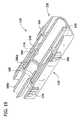
- FIG. 1is a perspective of a connector assembly with a first and second connector of the connector assembly engaged
- FIG. 2is a perspective of the connector assembly with the first and second connector separated
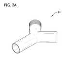
- FIG. 2Ais a perspective of a “Y” connector releasably attachable to the first or second connector
- FIG. 3is a perspective longitudinal section of the connector assembly shown in FIG. 1 ;
- FIG. 4is a perspective of the first connector of the connector assembly shown in FIG. 1 seen from an end and to a side;
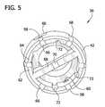
- FIG. 5is a perspective of the first connector seen substantially from the end
- FIG. 6is a perspective of the connector assembly shown in FIG. 1 having tubing attached;
- FIG. 7is a perspective of an alternate embodiment of the connector assembly showing two separated connectors with tubing attached;
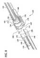
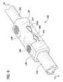
- FIG. 8is a perspective longitudinal section of the connector assembly shown in FIG. 7 ;
- FIG. 9is a perspective of another alternative embodiment of the connector assembly with tubing attached.
- FIG. 10is a perspective longitudinal section of the connector assembly as shown in FIG. 9 ;
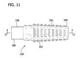
- FIG. 11is a side elevation of another alternative embodiment of the connector assembly with the first and second connectors engaged;
- FIG. 12is a longitudinal section of the connector assembly shown in FIG. 11 ;
- FIG. 13is a perspective of the first connector of the connector assembly shown in FIG. 11 ;
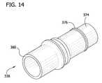
- FIG. 14is a perspective of the second connector of the connector assembly shown in FIG. 11 ;
- FIG. 15is a side elevation of another alternative embodiment of the connector assembly with the first and second connectors engaged;
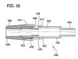
- FIG. 16is a longitudinal section of the connector assembly shown in FIG. 15 ;
- FIG. 17is a perspective of the first connector of the connector assembly shown in FIG. 15 ;
- FIG. 18is a perspective of the second connector of the connector assembly shown in FIG. 15 ;
- FIG. 19is perspective longitudinal section of the engaged first and second connector of the connector assembly shown in FIG. 9 ;
- FIG. 19Ais a perspective of the first and second connector separated of the connector assembly shown in FIG. 9 ;
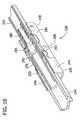
- FIG. 20is a perspective of an alternative embodiment of the connector assembly with first and second connectors of the connector assembly engaged;
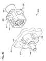
- FIG. 21is a perspective of the connector assembly with the first and second connectors separated
- FIG. 22is the perspective of FIG. 20 with the first and second housings removed;
- FIG. 23is an exploded perspective of the second connector shown in FIG. 22 ;
- FIG. 24is a perspective of the first connector assembly shown in FIG. 20 ;
- FIG. 25is a longitudinal section taken through opposed channels of a non-sealing surface of the first connector shown in FIG. 24 showing attempted attachment of a non-permitted conduit;
- FIG. 26is a perspective of an alternative embodiment of the first connector assembly
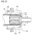
- FIG. 27is a longitudinal section taken through opposed channels of a non-sealing surface of the first connector shown in FIG. 26 showing attempted attachment of a non-permitted conduit;
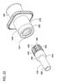
- FIG. 28is a perspective similar to FIG. 21 but showing a second connector of another embodiment
- FIG. 29is the perspective of FIG. 28 with the first and second housings removed;
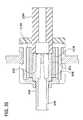
- FIG. 30is a longitudinal section through the mated first and second connectors of FIG. 28 ;
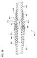
- FIG. 31is a perspective similar to FIG. 29 , but showing a second connector of yet another embodiment
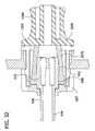
- FIG. 32is a longitudinal section through the mated first and second connectors of FIG. 31 ;
- FIG. 33is a perspective similar to FIG. 28 but showing a second connector of still another embodiment
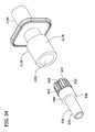
- FIG. 34is the perspective of FIG. 33 with the first and second housing removed;
- FIG. 35is a longitudinal section of the mated connectors of FIG. 34 ;
- FIG. 36is a perspective of a first connector of an alternate embodiment of the connector assembly
- FIG. 37is a perspective of a second connector of the connector assembly of FIG. 28 attached to tubing;
- FIG. 38is a longitudinal section of the connector assembly of FIGS. 36 and 37 with the first and second connectors of the connector assembly engaged;
- FIG. 39is a longitudinal section taken through opposed channels of a non-sealing surface of the first connector in FIG. 36 showing attempted attachment of a non-permitted conduit;
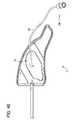
- FIG. 40is a perspective of a compression therapy device showing an inflatable bladder and an enlarged view of the connector
- FIG. 41is a perspective of a compression therapy device controller with an enlarged view of the connector.
- FIG. 42is an enlarged perspective of a tube set.
- FIGS. 1 and 2a connector assembly 30 constructed according to the principles of the present invention is shown in FIGS. 1 and 2 to comprise a first connector 36 and a second connector 38 .
- the first and second connectors 36 , 38are capable of discriminating connection to preferentially achieve fluid-tight connection of the connectors, and avoid fluid-tight connection with non-complying connectors.
- the connector system 30may be used, for example, to connect a controller 2 to a compression therapy device 1 for cyclically supplying air pressure to a bladder 4 of the device (see, FIGS. 40 and 41 ).
- the connector assembly 30can be used for other types of medical fluid connections such as the connection of an enteral feeding bag to a patient.
- a tube set 20( FIG. 42 ) is used to selectively interconnect the compression therapy device 1 and the controller 2 .
- the first connector 36is attached to a first tubing 32 of the tube set 20
- the second connector 38is attached to a second tubing 34 extending from the bladder 4 of the compression therapy device 1 ( FIG. 40 ).
- a third connector 10having substantially the same construction as the first connector 36 is attached to the controller 2 ( FIG. 41 )
- a fourth connector 26having substantially the same construction as the second connector 38 is attached to the opposite end of the tubing 32 of the tube set 20 ( FIG. 42 ).
- the fourth connector 26 of the tube set 20is engaged with the third connector 10 of the controller, and the first connector 36 of the tube set is engaged with the second connector 38 of the compression therapy device. Because of the structural identity of the first connector 36 and third connector 10 , and of the second connector 38 and the fourth connector 26 , only the first and second connectors will be described in detail hereinafter.
- the first connector 36has an attachment portion 40 that accepts the tubing 32 .
- the attachment portion 40could be directly connected to an object other than tubing, such as the third connector 10 is directly connected to the controller 2 ( FIG. 41 ).
- the second connector 38has an attachment portion 80 and a receptacle 78 .
- the receptacle 78has a roughly hourglass shape, so the user can grasp and hold the connector assembly 30 and to aid the user in engaging the second connector 38 to the first connector 36 , as shown in FIG. 1 .
- a coupling portion 42 of the first connector 36has a first end 44 and a second end 46 .
- the second end 46is suitably attached to the attachment portion 40 , such as by solvent bending or RF welding, or may be formed as one piece of material with the attachment portion.
- the attachment portion 40is sealingly received in the tubing 32 of the tube set 20 ( FIG. 42 ).
- the coupling portion 42includes a sealing surface 48 and a non-sealing surface 52 .
- the sealing surface 48extends around the perimeter of the coupling portion 42 at the second end 46 .
- the shape and contour of the coupling portion 42is not restricted to that of the illustrated embodiment, so long as the coupling portion can engage and form a seal with the second connector 38 , as will be described.
- the non-sealing surface 52has a greater diameter than the sealing surface 48 .
- a number of circumferentially spaced channels 58 in the non-sealing surface 52extend lengthwise of the first connection 36 .
- Two of the channels 58communicate with openings 60 extending radially through the first connector 36 to an inner surface 54 thereof.
- the channels 58 and openings 60operate to inhibit the formation of a sealing connection.
- the receptacle 78 of the second connector 38has an interior surface 74 and an annular shoulder 75 at the inner end of the interior of the receptacle ( FIG. 3 ).
- the shoulder 75defines a stop surface that limits the distance the first connector 36 can be inserted into the receptacle 78 and axially positions the first connector 36 with respect to the receptacle 78 .
- An annular sealing flange 76projects radially inward of the inner surface 74 of the receptacle 78 near the open end of the receptacle. As illustrated, the sealing flange 76 is formed as one piece of material with the receptacle 78 .
- a sealing membermay be formed separately from the receptacle (e.g., as an O-ring) and secured to the receptacle such as by being received in a circumferential groove formed in the inner surface of the receptacle.
- the usermust push, in the direction of the arrow “A” in FIG. 2 , the first end 44 of the first connector 36 into the receptacle 78 of the second connector 38 , such that the non-sealing surface 52 passes beyond the sealing flange 76 .
- a fluid tight sealwill not form because of longitudinal channels 58 disposed about the outer surface of coupling portion 42 .
- the sealing flange 76cannot conform into the channels 58 that extend past the flange allowing fluid to pass the flange on the non-sealing surface 52 of the first connector 36 .
- the sealing surface 48moves into registration with the sealing flange 76 , the flange is able to sealingly conform to the sealing surface to make a fluid tight connection with the sealing surface.
- the open space defined by the longitudinal channels 58prevents flush engagement of coupling portion 42 with the surface of a non-compliant connector or fluid conduit (lumen).
- the longitudinal channels 58may have widths, depths, or lengths other than illustrated herein.
- One or more longitudinal channels 58may be oriented parallel, offset, or undulating with the longitudinal axis of the connector 30 .
- the longitudinal channels 58can be replaced with a raised surface or roughness on the non-sealing surface 52 .
- the openings 60 defined through a wall 62help prevent a fluid seal between the first connector 36 and a non-compliant connector.
- An opening 60is not limited to size and shape provided the opening leaks with a non-compliant connector attached to the first connector 36 .
- One or more openings 60 diametrically opposed about the wall 62facilitate leakage with a non-compliant connector.
- An inner surface 54 of the first connector 36 and inner surface 74 of the second connector 38form a fluid pathway therethrough.
- the inner surfaces ( 54 , 74 )are formed to pass fluid according to the particular flow requirements of a medical system such as the controller 2 and compression therapy device 1 .
- Attachment portion 40 or attachment portion 80is not restricted to one port.
- a “Y” connector 84( FIG. 2A ) is releasably attachable to the attachment portion ( 40 , 80 ) of either connector 36 , 38 to increase the number of fluids or divert pressurized air to more than one bladder, in the case of compression sleeve.
- FIG. 3illustrates the connector assembly engaged, without the tubing 32 , 34 attached.
- the first tubing 32(not shown in FIG. 3 ) is sealingly attached to an inner surface 82 of the attachment portion 80 .
- the second tubing(not shown in FIG. 3 ) is attached to attachment portion 40 .
- the point contact “P”seals the connector assembly 30 upon contact between the sealing flange 76 and the sealing surface 48 of the first connector 36 .
- the tubing 32 , 34is attached in a suitable manner such as by using solvent bonding, RF welding, or other attaching means known in the art.
- FIGS. 4 and 5show a transverse wall 68 at the first end 44 of the first connector 36 .
- the transverse wall 68has a longitudinal cavity 70 across its face.
- the transverse wall 68extends along the longitudinal axis for substantially the length of the non-sealing surface 52 and inhibits the insertion of tubes or other connectors (not shown) into the first connector 36 .
- One or more longitudinal cavities 72extend along the inner surface 56 at the first end 44 .
- the non-sealing surface 52has a first face 64 with transverse cavities 66 disposed at spaced locations around the perimeter of the first face 64 .
- Each transverse cavity 66connects to a corresponding one of the longitudinal channels 58 formed in the wall 62 of the coupling portion 42 of first connector 36 .
- openings 60allow fluid to escape when a seal is not formed with the sealing surface 48 .
- the number and arrangement of channels 58 , openings 60 and cavities 66may be other than described without departing from the scope of the present invention.
- the cavities 66prevent a seal between the first face 64 and a surface of a non-compliant connector.
- Each cavity 66aligns with its corresponding outer longitudinal channels 58 to provide a path for leakage when the first connector 36 is inserted into a non-compliant connector.
- the transverse wall 68prevents inserting a non-compliant connector into the first connector 36 .
- the cavity 70helps prevent a sealing surface between the first face 64 and a surface of a non-complaint connector.
- inner longitudinal cavities 72 and the openings 60 though the wall 62help prevent sealing with a non-compliant connector on the inside or outside of the first connector 36 .
- the open spaces defined by the cavities 66prevent flush engagement with coupling portion 42 and a surface of a non-compliant connector.
- a cavity or channel ( 66 , 70 , 72 , 58 )is not limited to a specific width, depth, or length.
- a cavity or channel ( 66 , 70 , 72 , 58 )is not restricted to orientation and can be parallel, offset or undulating.
- the present inventionis not restricted to one non-sealing surface 52 or one sealing surface 48 .
- FIGS. 7 and 8illustrate an alternative connector assembly 130 .
- Parts of the connector assembly 130generally corresponding to those of the connector assembly 30 will be given the same number, plus “100.”
- a first connector 136 of the connector assembly 130has a first end 144 and a second end 146 . Located generally between the first and second ends 144 , 146 is a sealing surface 148 .
- the coupling portion 142is rectangular with rounded corners and sized to fit into the opening of a second connector 138 , in the direction of arrow “A”.
- the second connector 138defines a receptacle in a housing of the second connector to receive the first connector 136 .
- An outwardly flared non-sealing surface 152is located at the open end of the second connector 138 .
- Triangular channels 158 in the non-sealing surfaceprovide fluid communication paths to locations outside the connectors 136 , 138 to inhibit sealing.
- the userholds the second connector 138 using raised ribs 178 to grip and insert the first connector 136 into the second connector 138 .
- the ribs 178also prevent a sealing connection between the second connector 138 and a tube or the like (not shown) received over the exterior of the second connector.
- the first connector 136is inserted with its first end 144 passing beyond a sealing flange 176 located inside the second connector 138 .
- the resilient sealing flange 176conforms to the sealing surface 148 to form a fluid tight seal, after the sealing surface 148 passes beyond the non-sealing surface 152 and engages the flange 176 .
- a bar 181is located at the inner end of the second connector 138 to inhibit a tube (not shown) from sealingly abutting a first tube 132 inserted inside an attachment portion 180 of the second connector.
- the first tubing 132forms a sealing interference fit with the inner surface 182 of the attachment portion 180 .
- a second tubing 134is inserted over an attachment portion 140 ( FIG. 8 ), at the second end 146 of the coupling portion 142 .
- the first and second tubings 132 , 134are attached in suitable ways to the first and second connectors 136 , 138 . This forms a fluid conduit as part of a medical system when properly connected.
- FIGS. 9 and 10illustrate a connector assembly 230 comprising a key 252 and a mating cavity 290 .
- Parts of the connector assembly 230 corresponding to those of the connector assembly 30are given the same reference numeral, plus “200.”
- the connector assembly 230comprises a first connector 236 and a second connector 238 .
- the first connector 236has a tubular attachment portion 240 secured to an interior of a housing 241 of the first connector.
- the attachment portion 240can be sealingly received in a (second) tubing 234 .
- the second connector 238has an attachment portion 280 that can attach the second connector to a (first) tubing 232 .
- the second connector 238includes a housing 281 that mounts the attachment portion 280 by way of a flange 283 of the attachment portion.
- a gasket 276(broadly, “a sealing member”) mounted by the housing 281 is generally tubular in shape and includes ears 276 a that are received in correspondingly shaped openings 277 in the housing 281 .
- the gasket 276is received around and sealingly engages an exterior surface of the attachment portion 280 axially inward of the mounting flange 283 .
- Coupling portion 242is slidingly and sealingly received by a first end of second connector 238 into the gasket 276 to form a sealing connection between the first and second connectors.
- the key 252snaps into the mating cavity 290 to releasably lock the first and second connectors 236 , 238 is sealing connection.
- the userdepresses a button 286 , with raised edges, and pulls the first connector 236 from the second connector 238 , while holding the second connector 238 . Depressing the button 286 deforms the first connector and moves the key 252 laterally out of the cavity 290 .
- the key 252prevents engagement with a non-compliant connector (not shown).
- FIGS. 19 and 19AAn alternate embodiment of a keyed connector assembly 530 illustrated in FIGS. 19 and 19A is similar to the keyed connector assembly 230 of FIGS. 9 and 10 . Parts of the connector assembly 530 corresponding to those of the connector assembly 30 are given the same reference numeral, plus “500.”
- the first connector 536comprises a key 552 , guide flanges 553 and an inner rigid lumen or conduit 548 including an attachment portion 540 .
- the second connector 538comprises a mating cavity 590 , an inner sealing member 588 , and finger grips 578
- An attachment portion 580 located within the second connector 538includes an inner part 580 a that is sealingly attached to the sealing member 588 , and an outer part 580 b that can be attached to tubing (not shown).
- the usergrips the second connector 538 at the finger grips 578 , grips the first connector 536 and then pushes the key 552 toward the cavity 590 until it snaps into the cavity.
- the flanges 553engage the second connector 538 and help guide the first connector 536 into sealing engagement with the second connector.
- the inner end of the conduit 548is received in the sealing member 588 and seals with the sealing member by engagement with an annular protrusion 576 in the sealing member. In this way, a sealing connection of the first and second connectors 536 , 538 can be made.
- FIGS. 11-14illustrate still another alternate embodiment of a connector assembly 330 .
- Parts of the connector assembly 330 corresponding to those of the connector assembly 30are designated by the same reference numerals, plus “300.”
- Connector assembly 330comprises a first connector 336 ( FIG. 13 ), and a second connector 338 ( FIG. 14 ).
- First connector 336has an attachment portion 340 ( FIG. 12 ) that accepts tubing (not shown) on the inner surface 341 of the attachment portion 340 .
- the second connector 338( FIG. 14 ) has an attachment portion 380 at a first end and a cap 374 at the second end. A second tubing (not shown) can be received on attachment portion 380 .
- a deformable O-ring 376Spaced a distance from the second end is a deformable O-ring 376 around the perimeter of the cap 374 .
- the O-ring 376is releasably attached to the cap 374 .
- a sealing membercan be formed in any suitable manner such as an O-ring (as shown) or a raised surface of deformable plastic.
- the first connector 336further comprises a coupling portion 342 with at least one longitudinal channel 372 therethrough ( FIG. 13 ).
- a plurality of non-sealing surface 352 areasare disposed on the inside of the coupling portion 342 .
- the non-sealing surfaces 352have longitudinal channels 358 disposed on the inner surface of the first connector 336 to prevent a fluid seal with a non-compliant connector.
- the axially inner longitudinal channels 358are also disposed on both sides of a groove 349 that defines the sealing surface 348 ( FIG. 13 ).
- At the face of the coupling 342are disposed a plurality of longitudinal channels 372 ( FIG. 13 ). The open space defined by the channels 372 prevents the coupling portion 342 from forming a fluid seal with a surface of a non-compliant connector.
- the userinserts the cap 374 into the opening at the coupling portion 342 .
- the O-ring 376is deformed as it moves over the non-sealing surfaces 352 under the force of the user.
- the O-ring 376comes to rest in the groove 349 and engages the sealing surface 348 ( FIG. 13 ), to form a fluid tight seal.
- FIGS. 15-18illustrate a further embodiment of a connector assembly 430 .
- Parts of the connector assembly 430 corresponding to those of the connector assembly 30are given the same reference numerals, plus “400.”
- Connector assembly 430includes a first connector 436 and a second connector 438 .
- the first connector 436has an attachment portion 440 that can be attached to a lumen (not shown) which fluidly communicates with a fluid source.
- a lumen(or tubing) is received on an outer surface of attachment portion 440 and forms a fluid-tight seal therewith.
- the first connector 436has a coupling portion 442 comprising a sealing surface 448 and a pair of non-sealing surfaces 452 and each non-sealing surface 452 having longitudinal channels 458 ( FIG.
- the longitudinal channels 458are disposed on either side of the sealing surface 448 .
- the longitudinal channels 458prevent a sealing engagement with the coupling portion 442 by a non-compliant connector.
- a longitudinal channel 458can be oriented anywhere along the perimeter of the coupling portion 442 and can be of varying length, width or depth.
- a generally annular detent 479(broken by channels 458 ) extends around the first connector 436 .
- the non-sealing surface 452includes a first face 464 .
- the first face 464includes a transverse wall 468 that extends across the diameter of coupling portion 442 .
- Transverse wall 468is configured to prevent sealing engagement of the surface of coupling portion 442 with a non-compliant connector.
- the second connector 438comprises an attachment portion 480 , a cap 474 , an O-ring 476 inside the cap and sealingly mounted on the cap, and a flex collar 477 ( FIGS. 16 and 18 ).
- the userpushes the second connector 438 onto the coupling portion 442 , with the first face 464 entering the opening of the second connector 438 , at the flex collar end.
- the O-ring 476engages the leading non-sealing surface 452 and does not establish a sealing connection with the non-sealing surface because of the channels 458 .
- the O-ring 476next engages the sealing surface 448 as the first connector 436 is advanced farther into the second connector 438 and establishes a sealing connection between the first and second connectors.
- the detents 479 of the first connector 436are received in annular grooves 478 on the interior of the flex collar 477 .
- the flex collarwhich has been deflected from its relaxed position, bears against the detents 479 and holds them in the grooves 478 for securing the first and second connectors 436 , 438 together.
- FIGS. 20-25illustrate a further embodiment of a connector assembly 630 .
- Parts of the connector assembly 630 corresponding to those of the connector assembly 30are given the same reference numerals, plus “600.”
- the connector assembly 630includes a first connector 636 and second connector 638 .
- the first connector 636includes a first housing 657 , attachment portion 640 , and coupling portion 642 and the second connector 638 includes a second housing 659 , attachment portion 680 , and receptacle 678 .
- the first and second housings 657 , 659are removed in FIGS. 22 and 23 to better illustrate other features of the first and second connectors 636 , 638 .
- the first connector 636may be integral with or secured to another object or device such as a wall 643 (only a fragmentary portion being illustrated) of the housing of a controller like the controller 2 shown in FIG. 41 .
- the attachment portion 640 of the first connector 636accepts tubing (not shown, but like medical tubing 32 ) that extends from the pump within the controller.
- the attachment portion 640could be directly connected to an object other than tubing
- the coupling portion 642 of the first connector 636has a first end 644 and a second end 646 .
- the second end 646is suitably attached to the attachment portion 640 , such as by solvent bonding or RF welding, or may be formed as one piece of material with the attachment portion.
- the attachment portion 640may be sealingly received in tubing (e.g., tubing 32 of the tube set 20 ( FIG. 42 )).
- the coupling portion 642includes a sealing surface 648 and a non-sealing surface 652 .
- the non-sealing surface 652is closer to the free end of the first connector 636 than the sealing surface 648 .
- the sealing surface 648extends around the perimeter of the coupling portion 642 at the second end 646 .
- the shape and contour of the coupling portion 642is not restricted to that of the illustrated embodiment, so long as the coupling portion can engage and form a seal with the second connector 638 , as will be described.
- the non-sealing surface 652has a greater diameter than the sealing surface 648 .
- a number of circumferentially spaced channels 658 in the non-sealing surface 652extend lengthwise of the first connector 636 . The channels 658 operate to inhibit the formation of a sealing connection with an interior surface of medical tubing.
- the second connector 638has a deformable O-ring 663 at the end of the receptacle 678 opposite the attachment portion 680 , which is captured by a cap 655 .
- the cap 655fits over the O-ring 663 and makes a sna connection with a tapered end 665 of the receptacle 678 to capture the O-ring between the cap and the face 667 of the receptacle.
- the O-ring 663protrudes radially inward from between the end face 667 of the receptacle 678 and the cap 655 such that the O-ring can sealingly engage the sealing surface 648 of the first connector 636 when the first connector 636 is received in the second connector 638 .
- the attachment portion 680 of the second connector 638tapers in diameter toward its middle to facilitate gripping of the second connector assembly 639 .
- the attachment portion 680may sealingly receive generic tubing (e.g., tubing 32 of the tube set 20 ( FIG. 42 )).
- the second connector 638includes a key 611 having a projecting member 621 .
- the first connector 636includes a mating cavity 613 .
- the userTo form a seal between the first connector 636 and the second connector 638 , the user must push the first end 644 of the first connector through the O-ring 663 and into the receptacle 678 of the second connector 638 , such that the non-sealing surface 652 passes beyond the O-ring.
- the sealing surface 648has engaged the O-ring 663 .
- Abutment of the projecting member 621 and the first housing 657prevents separation of the first connector 636 and the second connector 638 .
- the userdepresses the projecting member 621 and pulls the first connector 636 from the second connector 638 , while holding the second connector. Depressing the projecting member 621 moves the projecting member out of the mating cavity 613 .
- the first housing 657 of the first connector 636includes a floor 671 .
- the coupling portion 642projects outward from the floor 671 .
- Standoff ribs 675 that project outward from the housing floor 671are circumferentially spaced about the coupling portion 642 .
- the end of each standoff rib 675 adjacent the coupling portion 642is attached to a connecting segment 681 that circumferentially surrounds the coupling portion.
- Bleed passages generally indicated at 679are defined beyond the connecting segments 681 and between the ribs 675 and floor 671 .
- the bleed passages 679extend past the end face of a conduit such as generic medical tubing, when the conduit is fully inserted onto the coupling portion 642 that allows fluid to be bled around the coupling portion to prevent a fluid-tight seal.
- the direction and pathway of flowis generally indicated by arrow “A” ( FIG. 25 ).
- the bleed passages 679prevent successful fluid-tight connection between the coupling portion and medical tubing MT (a “non-permitted conduit”) when the end face of the medical tubing is pushed all the way into the first housing 657 as illustrated in FIG. 25 . In this condition, a typical controller can sense the absence of the fluid tight connection and initiate an alarm.
- FIGS. 26 and 27illustrate a further embodiment of the first connector 736 .
- Parts of the first connector 736 corresponding to those of the connector 636are given the same reference numerals, plus “100.”
- Bleed passages 779are formed in the first connector 736 and located generally adjacent the floor 771 of the housing 757 for bleeding fluid around the coupling portion 742 .
- the bleed passages 779open radially outward of the coupling portion 742 at a first opening and extend axially through the housing floor 771 and open from the first connector at the side of the floor opposite the first opening.
- a non-sealing surface 752 of the coupling portion 742holds conventional medical tubing MT (a “non-permitted conduit”) from sealing with the sealing surface 748 .
- An end face of the tubing MTmay seal with the floor 771 .
- the bleed passages 779 formed in the sealing surface 748are not sealed.
- air in the medical tubing MTmay pass through the channels 758 in the non-sealing surface 752 , along the sealing surface 748 and out the bleed passages 779 as indicated by arrow “B” ( FIG. 27 ). Therefore, no fluid-tight connection can be made with standard medical tubing MT, even if the end face of the tubing otherwise seals with the floor 771 .
- FIGS. 28-30illustrate a further embodiment of the second connector 938 .
- Parts of the second connector 938 corresponding to those of the connector 638are given the same reference numerals, plus “300.”
- the second connector 938includes a second housing 959 , attachment portion 980 , and conduit 978 .
- the first and second housings 657 , 959are removed in FIG. 29 to better illustrate other features of the first and second connectors 636 , 938 .
- the attachment portion 980may sealingly receive and being sealingly joined to generic tubing (e.g., medical tubing 32 of the tube set 20 ( FIG. 42 )).
- the second connector 938does not include a deformable O-ring, but, rather, the conduit (or “receptacle”) 978 itself is adapted so that the open outer end is capable of receiving both the large diameter non-sealing surface 652 and the smaller diameter sealing surface 648 and is capable of forming a fluid-tight seal with the sealing surface upon connection of the first connector 636 and second connector 938 .
- At least one of the hardness and the wall thickness of the conduit 978must be selected such that the open outer end of the conduit receives the large diameter non-sealing surface 652 and forms a fluid-tight seal with the sealing surface 648 .
- tubes made of polyvinylchloride (PVC) with a hardness of from about 50 durometer (type A) to about 70 durometer (type A) and a thickness of from about 50 mil to about 100 mil (about 1.27 mm to about 2.54 mm)are capable of receiving the large diameter non-sealing surface 652 and forming a fluid-tight seal with the sealing surface 648 .
- PVCpolyvinylchloride
- these characteristicsare selected to be different from standard medical tubing.
- FIG. 30illustrates a cross-section of the first connector 636 connected to the second connector 938 .
- the housing 959is made of a material that is more rigid than the material of the conduit 978 and the conduit is mounted on the housing.
- the conduit 978deforms itself over the non-sealing surface 652 and forms a fluid-tight seal with the sealing surface 648 .
- the hardness and the wall thickness of the conduit 978is selected so that it will deform into sealing engagement with the sealing surface 648 of the first connector 636 while remaining in engagement with the non-sealing surface 642 , as shown in FIG. 30 .
- the first connector 636is a male connector and the second connector 938 is a female connector, the roles could be reversed within the scope of the present invention. In that event, the conduit would be received inside a first connector.
- the second connector 938is shown with a housing 959 , the second connector may form the end of a tube and not have a housing or attachment portion 980 without departing from the scope of the present invention.
- the second connector 938may form an end of the tubing 32 ( FIG. 41 ) or the end of the second tubing 34 extending from the bladder 4 of the compression therapy device 1 ( FIG. 40 ).
- FIGS. 31-32illustrate a further embodiment of the second connector 1038 .
- Parts of the second connector 1038 corresponding to those of the connector 638are given the same reference numerals, plus “400.”
- the first and second housingsare removed in FIG. 32 to better illustrate other features of the first and second connectors 636 , 1038 .
- the second connector 1038differs from the second connector 938 in that the conduit 1078 of the second connector flares outward in diameter toward the free end of the second connector. This allows the outer end of the conduit 1078 to more easily receive the larger diameter non-sealing surface 652 .
- At least one of the hardness and the thickness of the conduit 1078is selected so that the open outer end of the conduit 1078 is capable of receiving the large diameter non-sealing surface 652 and forming a fluid-tight seal with the sealing surface 648 .
- flared conduits 1078with a hardness of from about 50 durometer (type A) to about 70 durometer (type A) and with a thickness of from about 30 mil to about 125 mil (about 0.762 mm to about 03.18 mm) are capable of receiving the large diameter non-sealing surface 652 and forming a fluid-tight seal with the sealing surface 648 .
- the inner diameter of the conduit 1078 at the open outer endis still less than the diameter of the sealing surface 648 of the first connector 636 .
- the second connectormay form the end of a tube (e.g., the tubing 32 ( FIG. 42 ) or the end of the second tubing 34 extending from the bladder 4 of the compression therapy device 1 ( FIG. 40 )) and not have a housing 1059 or attachment portion 1080 without departing from the scope of the present invention.
- a tubee.g., the tubing 32 ( FIG. 42 ) or the end of the second tubing 34 extending from the bladder 4 of the compression therapy device 1 ( FIG. 40 )
- FIGS. 33-35illustrate a further embodiment of the second connector 1138 .
- Parts of the second connector 1138 corresponding to those of the connector 638are given the same reference numerals, plus “500.”
- the second connector 1138includes a second housing 1159 and conduit 1178 .
- the first and second housingsare removed in FIG. 34 to better illustrate other features of the first and second connectors 636 , 1138 .
- the conduit 1178is connected to a first end 1192 of a tube 1194 .
- the tube 1194may be tubing 32 of a tube set ( FIG. 42 ) or tubing 34 extending from the bladder 4 of the compression therapy device 1 ( FIG. 40 ).
- the first end 1192 of the tube 1194extends into the inner end of the conduit 1178 .
- the inside diameter of the conduit 1178 and the outside diameter of the first tube 1194are generally the same. This allows the conduit 1178 to be suitably attached to the first end 1192 of the tube 1194 , such as by solvent bending or RF welding, or the conduit 1178 may be formed as one piece of material with the tube. It will be appreciated that the flared conduit 1078 could be directly attached to a tube in the same manner (not shown).
- At least one of the hardness and the thickness of the conduit 1178is selected such that the open outer end of the conduit 1178 is capable of receiving the large diameter non-sealing surface 652 and forming a fluid-tight seal with the sealing surface 648 .
- flared conduits 1178with a hardness of from about 50 durometer (type A) to about 70 durometer (type A) and with a thickness of from about 30 mil to about 125 mil (about 0.762 mm to about 03.18 mm) are capable of receiving the large diameter non-sealing surface 652 and forming a fluid-tight seal with the sealing surface 648 .
- the second connector 1138is illustrated with a housing 1159 , the second connector may lack a housing without departing from the scope of the present invention.
- FIGS. 36-39illustrate a further embodiment of a connector assembly 830 .
- the connector assembly 830comprises a first connector 836 and a second connector 838 ( FIGS. 36 and 37 ).
- the first connector 836has a tubular and barbed attachment portion 840 secured to a gripping portion 841 of the first connector and located in an interior of the gripping portion ( FIG. 38 ).
- the attachment portion 840can be sealingly received in tubing 834 .
- the attachment portion 840could be directly connected to an object other than tubing, in the same way as the third connector 10 is directly connected to the controller 2 .
- the second connector 838has an attachment portion 880 that can attach the second connector to generic tubing 832 (e.g., like tubing 32 of the tube set 20 ( FIG. 42 )).
- the second connector 838includes a receptacle 878 .
- the receptacle 878mounts to the attachment portion 880 by way of a flange 883 .
- the receptacle 878has an interior surface 874 and an annular shoulder 875 at the inner end of the interior of the receptacle ( FIG. 38 ).
- the shoulder 875defines a stop surface that limits the distance the first connector 836 can be inserted into the receptacle 878 and axially positions the first connector 836 with respect to the receptacle 878 .
- the surface of the gripping portion 841 of the first connector 836 and the surface of the attachment portion 880 of the second connector 838include raised ridges 814 , 824 .
- the raised ridges 814 of the first connector 836include two generally opposed parentheses shaped first ridges 814 a that extend generally lengthwise of the first connector and two flattened U-shaped second ridges 814 b spaced lengthwise of the first connector and located between the first ridges ( FIG. 36 ).
- the raised ridges 824include first ridges 824 a and second ridges 824 b shaped and arranged in the same way as the first ridges 814 a and second ridges 814 b (see, FIG. 37 ).
- first and second ridges 814 a , 814 b and 824 a , 824 bare arranged to define channels 822 , 828 (respectively) for the passage of air along the connector 836 , 838 .
- the raised ridges generally indicated at 814 and 824respectively, prevent a fluid-tight seal from forming when generic medical tubing is placed over the surface of the gripping portion 841 or of the attachment portion 880 .
- Channels 822 , 828 defined by the raised ridges 814 , 824carry fluid away from the connectors 836 , 838 in a direction generally indicated by arrow “A” if such tubing (not shown) is placed over the connectors thereby inhibiting a fluid tight connection of either of the connectors 836 , 838 with the medical tubing.
- the second ridges 814 b , 824 bhelp to prevent highly conforming tube material from sealing with and between the first ridges 814 a , 824 b.
- the ridges 814 and 824may have shapes and arrangements that are different from what is illustrated and different from each other within the scope of the present invention. As shaped and arranged in the illustrated embodiment, the ridges 814 , 824 provide for the passage of air, but also facilitate gripping the connector 836 , 838 . In the illustrated embodiment there are ridges (not shown) just like the ridges 814 , 824 that may be seen in FIGS. 36 and 37 , but which are located in the opposite sides of the connectors 836 , 838 .
- the gripping portion 841 of the first connector 836has a flange 815 formed at a distal end.
- the first connector 836includes a coupling portion 842 and a floor 871 .
- the diameter of the floor 871is generally the same as the diameter of the flange 815 .
- the floor 871 and flange 815include bleed passages 817 at their perimeters to prevent a fluid-tight seal when medical tubing is placed over the perimeters of the flange and floor.
- Another pair of bleed passageslike bleed passages 817 are located at the opposite side of the connector 836 . It will be understood that any number of bleed passages may be employed within the scope of the present invention.
- the first connector 836includes a coupling portion 842 that projects outward from the floor 871 .
- Standoff ribs 875 that project outward from the floor 871are circumferentially spaced about the coupling portion 842 .
- Bleed passages generally indicated at 879are defined between the ribs 875 and floor 871 .
- the bleed passages 879are recessed from the ribs 875 and communicate with bleed passages 817 . If a medical tube MT that is too small to receive the entire connector 836 therein is pushed over the coupling portion 842 as illustrated in FIG. 39 , an end of the tubing engages the ribs 875 and is held off the floor 871 .
- Airmay flow out of the tube, into the bleed passages 879 to bleed passages 817 or directed radially outward of the first connector 836 .
- the direction and pathway of flowis generally indicated by arrow “A” ( FIG. 39 ).
- the bleed passages 817 , 879prevent successful fluid-tight connection between the coupling portion 842 and medical tubing when the end face of the medical tubing is pushed all the way to the floor 871 .
- the coupling portion 842includes a sealing surface 848 and a non-sealing surface 852 .
- the non-sealing surfaceis closer to the free end of the first connector 836 than the sealing surface 848 .
- the sealing surfaceextends around the perimeter of the coupling portion 842 .
- the shape and contour of the coupling portion 842is not restricted to that of the illustrated embodiment, so long as the coupling portion can engage and form a seal with the second connector 838 , as will be described.
- the non-sealing surface 852has a greater diameter than the sealing surface 848 .
- a number of circumferentially spaced channels 858 in the non-sealing surface 852extend lengthwise of the first connector 836 . The channels 858 operate to inhibit the formation of a sealing connection of the coupling portion 842 with an interior surface of medical tubing.
- the second connector 838has a deformable O-ring 863 at the end of the receptacle 878 opposite the attachment portion 880 .
- the O-ring 863protrudes radially inward and is positioned axially so that the O-ring can sealingly engage the sealing surface 848 of the first connector 836 when the first connector 836 is received in the second connector 838 to make a fluid-tight connection. In this way, essentially only desired connections are allowed.
- the connectorsare fabricated from semi-flexible and flexible materials suitable for vascular compression therapy such as, for example, polymeric materials, depending on the particular vascular therapy application and/or preference. Urethanes and silicones may also be used. One skilled in the art, however, will realize that other materials and fabrication methods suitable for assembly and manufacture, in accordance with the present disclosure, also would be appropriate. A number of alternating sealing and non-sealing surfaces is possible depending on the size and shape of the connector assembly.
Landscapes
- Health & Medical Sciences (AREA)
- Engineering & Computer Science (AREA)
- Heart & Thoracic Surgery (AREA)
- General Engineering & Computer Science (AREA)
- Hematology (AREA)
- Biomedical Technology (AREA)
- Anesthesiology (AREA)
- Life Sciences & Earth Sciences (AREA)
- Animal Behavior & Ethology (AREA)
- General Health & Medical Sciences (AREA)
- Public Health (AREA)
- Veterinary Medicine (AREA)
- Pulmonology (AREA)
- Mechanical Engineering (AREA)
- Infusion, Injection, And Reservoir Apparatuses (AREA)
Abstract
Description
Claims (14)
Priority Applications (1)
| Application Number | Priority Date | Filing Date | Title |
|---|---|---|---|
| US12/052,282US8257287B2 (en) | 2008-03-20 | 2008-03-20 | Safety connector assembly |
Applications Claiming Priority (1)
| Application Number | Priority Date | Filing Date | Title |
|---|---|---|---|
| US12/052,282US8257287B2 (en) | 2008-03-20 | 2008-03-20 | Safety connector assembly |
Publications (2)
| Publication Number | Publication Date |
|---|---|
| US20090240178A1 US20090240178A1 (en) | 2009-09-24 |
| US8257287B2true US8257287B2 (en) | 2012-09-04 |
Family
ID=41089622
Family Applications (1)
| Application Number | Title | Priority Date | Filing Date |
|---|---|---|---|
| US12/052,282Active2031-05-29US8257287B2 (en) | 2008-03-20 | 2008-03-20 | Safety connector assembly |
Country Status (1)
| Country | Link |
|---|---|
| US (1) | US8257287B2 (en) |
Cited By (8)
| Publication number | Priority date | Publication date | Assignee | Title |
|---|---|---|---|---|
| USD709187S1 (en)* | 2012-05-08 | 2014-07-15 | Maymom | Tubing connector for breast pumps |
| US20180055286A1 (en)* | 2015-03-09 | 2018-03-01 | De' Longhi Appliances S.R.L. Con Unico Socio | Closing device for an apparatus for cooking food products |
| US10207096B2 (en) | 2013-02-27 | 2019-02-19 | Fresenius Medical Care Holdings, Inc. | Fluid line connectors |
| US10238855B2 (en) | 2013-11-06 | 2019-03-26 | Fresenius Medical Care Deutschland Gmbh | Connector with seal element and adapted connector parts |
| US10391019B2 (en) | 2007-04-13 | 2019-08-27 | Stryker Corporation | Patient support with universal energy supply system |
| US10667984B2 (en) | 2015-12-18 | 2020-06-02 | Stryker Corporation | Systems and methods for operating patient therapy devices |
| US11410771B2 (en) | 2017-06-01 | 2022-08-09 | Stryker Corporation | Patient care devices with open communication |
| USRE49287E1 (en) | 2009-04-15 | 2022-11-08 | Kiwi Connection, Llc | Socket structure with duplex electrical connection |
Families Citing this family (13)
| Publication number | Priority date | Publication date | Assignee | Title |
|---|---|---|---|---|
| EP2616136B1 (en)* | 2010-09-14 | 2017-03-29 | Cedic S.r.l. | Medical connector |
| US9220883B2 (en) | 2010-09-14 | 2015-12-29 | Cedic S.R.L. | Medical connector |
| EP3034121A1 (en)* | 2012-12-17 | 2016-06-22 | Koninklijke Philips N.V. | Rotary fluid coupler |
| TWI549675B (en)* | 2013-02-07 | 2016-09-21 | Dong-He Wu | Massage plate combination positioning structure |
| US11446462B2 (en) | 2015-03-31 | 2022-09-20 | Fisher & Paykel Healthcare Limited | Apparatus for use in a respiratory support system |
| WO2017037660A1 (en)* | 2015-09-04 | 2017-03-09 | Fisher & Paykel Healthcare Limited | Connectors for conduits |
| USD809656S1 (en) | 2016-06-10 | 2018-02-06 | Fisher & Paykel Healthcare Limited | Connector for a breathing circuit |
| USD948027S1 (en) | 2019-09-10 | 2022-04-05 | Fisher & Paykel Healthcare Limited | Connector for a breathing conduit |
| USD940861S1 (en) | 2020-03-03 | 2022-01-11 | Fisher & Paykel Healthcare Limited | Connector for a respiratory system conduit |
| AU2021275323A1 (en)* | 2020-05-22 | 2022-12-22 | Kpr U.S., Llc | System, method, and device utilizing reversible connector |
| USD974551S1 (en) | 2020-12-09 | 2023-01-03 | Fisher & Paykel Healthcare Limited | Connector assembly and connector |
| USD1073919S1 (en) | 2021-05-17 | 2025-05-06 | Fisher & Paykel Healthcare Limited | Respiratory system conduit with connector |
| USD995758S1 (en) | 2021-06-11 | 2023-08-15 | Fisher & Paykel Healthcare Limited | Tube assembly and connector |
Citations (183)
| Publication number | Priority date | Publication date | Assignee | Title |
|---|---|---|---|---|
| US2280485A (en) | 1942-04-21 | Calculating device | ||
| US2694395A (en) | 1951-05-10 | 1954-11-16 | William J Brown | Pneumatic pressure garment |
| US2694393A (en) | 1951-07-11 | 1954-11-16 | William E Simpson | Weed burner |
| FR1171861A (en) | 1957-04-24 | 1959-01-30 | Improvements to closed-circuit anesthesia machines | |
| US2893395A (en) | 1957-02-08 | 1959-07-07 | Becton Dickinson Co | Medical assembly and unit for liquid transfer |
| US3057001A (en) | 1958-06-23 | 1962-10-09 | Illinois Tool Works | Strain relief grommet |
| US3097866A (en) | 1960-11-14 | 1963-07-16 | Weatherhead Co | Pressurized hose end |
| US3287031A (en) | 1964-09-21 | 1966-11-22 | William H Simmons | Indexed keyed connection |
| US3454006A (en) | 1966-01-28 | 1969-07-08 | Weck & Co Inc Edward | Intravenous catheter-needle assembly provided with needle bushing guide |
| US3625212A (en) | 1969-07-09 | 1971-12-07 | North American Biolog Inc | Eliminating mistakes in plasmapheresis |
| US3728875A (en) | 1971-01-07 | 1973-04-24 | Kendall & Co | Stocking with soft inner thigh area |
| US3733577A (en) | 1970-02-16 | 1973-05-15 | Bunker Ramo | Electrical two-part connectors |
| US3834388A (en) | 1973-01-29 | 1974-09-10 | Cenco Medical Health Supply Co | Suction control arrangement for a suction catheter |
| US4013069A (en) | 1975-10-28 | 1977-03-22 | The Kendall Company | Sequential intermittent compression device |
| US4029087A (en) | 1975-10-28 | 1977-06-14 | The Kendall Company | Extremity compression device |
| US4030488A (en) | 1975-10-28 | 1977-06-21 | The Kendall Company | Intermittent compression device |
| US4066084A (en) | 1974-01-14 | 1978-01-03 | Hans Tillander | Blood emptying device |
| US4091804A (en) | 1976-12-10 | 1978-05-30 | The Kendall Company | Compression sleeve |
| US4149529A (en) | 1977-09-16 | 1979-04-17 | Jobst Institute, Inc. | Portable thermo-hydraulic physiotherapy device |
| US4150673A (en) | 1977-02-03 | 1979-04-24 | Pharmachem Corporation | Coded entry system for blood bag |
| US4156425A (en) | 1977-08-10 | 1979-05-29 | The Kendall Company | Protective compression sleeve |
| US4198961A (en) | 1979-01-12 | 1980-04-22 | The Kendall Company | Compression device with sleeve retained conduits |
| US4207876A (en) | 1979-01-12 | 1980-06-17 | The Kendall Company | Compression device with ventilated sleeve |
| US4207875A (en) | 1979-01-12 | 1980-06-17 | The Kendall Company | Compression device with knee accommodating sleeve |
| US4211439A (en) | 1978-07-26 | 1980-07-08 | Moldestad Jon P | Safety device for hose connections |
| DE2907832A1 (en) | 1979-02-28 | 1980-09-04 | Fresenius Chem Pharm Ind | Syringe or catheter union - has two halves inside enclosing sleeves with one larger than other |
| WO1981000053A1 (en) | 1979-07-04 | 1981-01-22 | Travenol Lab Pty Ltd | Sterile fluid line coupling members |
| US4253449A (en) | 1979-08-09 | 1981-03-03 | The Kendall Company | Compression device with connection system |
| US4280723A (en) | 1978-07-26 | 1981-07-28 | Moldestad Jon P | Safety device for hose connections |
| US4280485A (en) | 1980-04-11 | 1981-07-28 | The Kendall Company | Compression device with simulator |
| US4369781A (en) | 1981-02-11 | 1983-01-25 | Sherwood Medical Industries Inc. | Luer connector |
| EP0151519A1 (en) | 1984-01-25 | 1985-08-14 | E.R. Squibb & Sons, Inc. | Quick disconnect tube coupling |
| US4580816A (en) | 1984-01-25 | 1986-04-08 | E. R. Squibb & Sons, Inc. | Quick disconnect tube coupling |
| US4619640A (en) | 1984-08-17 | 1986-10-28 | Potolsky Abraham I | Blood transfusion connector assembly |
| US4762504A (en) | 1986-02-19 | 1988-08-09 | Molex Incorporated | Connector coupling lock |
| US4790567A (en) | 1985-07-31 | 1988-12-13 | Kawasumi Laboratories, Inc. | Connector for plasmapheresis bag |
| US4795429A (en) | 1987-10-28 | 1989-01-03 | Feldstein Marvin A | Method and apparatus for use in the control of intravenous medication introduction |
| US4804208A (en) | 1986-08-11 | 1989-02-14 | The Kendall Company | Manifold coupling assembly |
| USD300177S (en) | 1986-05-08 | 1989-03-07 | Baxter Travenol Laboratories, Inc. | Spike connector with reverse taper |
| US4824145A (en) | 1986-06-06 | 1989-04-25 | Gambro Ab | Coupling components |
| USRE32939E (en) | 1983-06-22 | 1989-06-06 | Electro-Biology, Inc. | Medical appliance |
| US4867699A (en) | 1988-04-06 | 1989-09-19 | Amp Incorporated | Connector with checking device |
| US4872736A (en) | 1988-04-19 | 1989-10-10 | American Telephone And Telegraph Company, At&T Bell Laboratories | Connector assembly having a latching mechanism |
| US4887849A (en) | 1988-02-02 | 1989-12-19 | Hutchinson | Connection system for interconnecting a heat exchanger and a pipe union |
| WO1990012606A2 (en) | 1989-04-10 | 1990-11-01 | Baxter International Inc. | iRE-SLIT INJECTION SITE AND TAPERED CANNULA |
| US4988062A (en) | 1988-03-10 | 1991-01-29 | London Robert A | Apparatus, system and method for organizing and maintaining a plurality of medical catheters and the like |
| US5007411A (en) | 1989-04-12 | 1991-04-16 | The Kendall Company | Device for applying compressive pressures against a patient's limb |
| US5009252A (en) | 1990-05-03 | 1991-04-23 | The United States Of America As Represented By The Secretary Of The Army | Air distribution connector valve |
| US5022387A (en) | 1987-09-08 | 1991-06-11 | The Kendall Company | Antiembolism stocking used in combination with an intermittent pneumatic compression device |
| US5031604A (en) | 1989-04-12 | 1991-07-16 | The Kendall Company | Device for applying compressive pressures to a patient's limb |
| US5041025A (en) | 1990-01-31 | 1991-08-20 | Thomas & Betts Corporation | Interconnectable components employing a multi-positionable key |
| US5062550A (en) | 1990-05-24 | 1991-11-05 | Singh Bharat H | Selective flow dispensing container |
| US5117812A (en) | 1990-11-05 | 1992-06-02 | The Kendall Company | Segmented compression device for the limb |
| US5123677A (en) | 1990-05-31 | 1992-06-23 | Swagelok-Quick Connect Co. | All plastic quick-connect coupling |
| US5156603A (en) | 1989-03-14 | 1992-10-20 | Svend Andersen Plastic Industri A/S | Slide valve |
| US5165728A (en) | 1990-02-15 | 1992-11-24 | Gambro Dialysatoren Gmbh & Co. Kg | Nipple intended to cooperate with multiple coupling components |
| US5176406A (en) | 1990-12-20 | 1993-01-05 | Straghan Robert G | Coupling |
| US5186163A (en) | 1991-11-25 | 1993-02-16 | The Kendall Company | Compression device |
| US5190534A (en) | 1990-12-07 | 1993-03-02 | Delmed, Inc. | Prefilled sterilant fluid releasable coupling connector apparatus for catheter applications |
| US5215538A (en) | 1992-02-05 | 1993-06-01 | Abbott Laboratories | Connector-activated in-line valve |
| US5217384A (en) | 1991-07-26 | 1993-06-08 | Merit-Elektrik Gmbh | Mechanical locking on plug connection between electrical switch and connecting plug |
| US5219185A (en) | 1990-11-13 | 1993-06-15 | Itw Fastex Italia S.P.A. | Snap-on fluidtight pipe connecting device |
| US5224932A (en) | 1988-09-27 | 1993-07-06 | Venivee, Inc. | System for intravenous administration of a plurality of medicaments and/or nutrients |
| US5240289A (en) | 1991-05-10 | 1993-08-31 | Mannesmann Aktiengesellschaft | Plug-type connection for a tubular body |
| US5249830A (en) | 1990-02-02 | 1993-10-05 | Etablissements Caillau | Device for locking two coaxial tubes |
| US5263945A (en) | 1991-08-27 | 1993-11-23 | Contech Packaging, Inc. | Female Luer fitting with spirally spaced interior locking protuberances |
| US5273254A (en) | 1992-07-23 | 1993-12-28 | Huron Products Industries, Inc. | Fluid conduit quick connectors with anti-spill valves |
| US5285776A (en) | 1991-01-14 | 1994-02-15 | Volker Bertram | Adaptor with tracheal tube |
| EP0585633A1 (en) | 1992-08-13 | 1994-03-09 | Molex Incorporated | Latchable electrical connector system |
| US5330366A (en) | 1992-08-04 | 1994-07-19 | Yazaki Corporation | Connector with unlocking member |
| US5354260A (en) | 1993-05-13 | 1994-10-11 | Novamedix, Ltd. | Slipper with an inflatable foot pump |
| US5370423A (en) | 1992-02-28 | 1994-12-06 | Guest; John D. | Tube couplings |
| EP0634190A2 (en) | 1993-07-13 | 1995-01-18 | Anton Prof. Dr. Härle | Connector for medical cavity tube |
| US5383894A (en) | 1993-07-30 | 1995-01-24 | The Kendall Co. | Compression device having stepper motor controlled valves |
| US5387110A (en) | 1993-11-12 | 1995-02-07 | International Business Machines Corporation | Reversible dual media adapter cable |
| USD357736S (en) | 1993-09-16 | 1995-04-25 | The Kendall Company | Connector for device for applying compressive pressure to the leg |
| US5435009A (en) | 1992-10-01 | 1995-07-25 | Huntleigh Technology Plc | Inflatable compression garment |
| US5437610A (en) | 1994-01-10 | 1995-08-01 | Spinal Cord Society | Extremity pump apparatus |
| US5443289A (en) | 1992-11-11 | 1995-08-22 | Guest; John D. | Tube couplings |
| USD363988S (en) | 1994-04-26 | 1995-11-07 | The Kendall Company | Connector for applying compressive pressure to the leg |
| US5478119A (en) | 1993-09-16 | 1995-12-26 | The Kendall Company | Polarized manifold connection device |
| US5507732A (en) | 1994-10-05 | 1996-04-16 | Medtronic, Inc. | Quick assembly catheter manifold |
| US5509911A (en) | 1992-11-27 | 1996-04-23 | Maxxim Medical, Inc. | Rotating adapter for a catheterization system |
| US5546934A (en) | 1994-09-26 | 1996-08-20 | Respironics, Inc. | Resuscitator |
| USD375357S (en) | 1995-03-10 | 1996-11-05 | Medela, Inc. | Tubing connector for a breast pump assembly |
| US5575762A (en) | 1994-04-05 | 1996-11-19 | Beiersdorf-Jobst, Inc. | Gradient sequential compression system and method for reducing the occurrence of deep vein thrombosis |
| US5588954A (en) | 1994-04-05 | 1996-12-31 | Beiersdorf-Jobst, Inc. | Connector for a gradient sequential compression system |
| US5588955A (en) | 1993-07-08 | 1996-12-31 | Aircast, Inc. | Method and apparatus for providing therapeutic compression for reducing risk of DVT |
| US5591200A (en) | 1994-06-17 | 1997-01-07 | World, Inc. | Method and apparatus for applying pressure to a body limb for treating edema |
| US5591143A (en) | 1993-04-02 | 1997-01-07 | Medrad Inc. | Luer connector with torque indicator |
| US5626556A (en) | 1994-07-26 | 1997-05-06 | The Kendall Company | Hook and loop attachment for a compression sleeve and method of attaching a hook and loop fastener to a compression sleeve |
| US5637102A (en) | 1995-05-24 | 1997-06-10 | C. R. Bard, Inc. | Dual-type catheter connection system |
| US5695224A (en) | 1995-08-14 | 1997-12-09 | The Rovac Corporation | Pipe joint assembly |
| US5711757A (en) | 1993-10-20 | 1998-01-27 | Neoligaments Limited | Controller especially for pneumatic continuous passive motion devices |
| US5725511A (en) | 1995-09-07 | 1998-03-10 | Urrutia; Sharon A. | Method and apparatus for prevention of blood-type mismatches |
| US5725425A (en) | 1994-04-27 | 1998-03-10 | Auto Electronics Corporation | Sensor system for controlling ventilation systems in vehicles |
| EP0832666A2 (en) | 1996-09-30 | 1998-04-01 | Becton, Dickinson and Company | Detachable blood seal |
| US5735841A (en) | 1995-03-13 | 1998-04-07 | Nestec, Ltd. | Non-spikable connector |
| US5743755A (en) | 1995-12-22 | 1998-04-28 | Yazaki Corporation | Connector system |
| WO1998022175A1 (en) | 1996-11-21 | 1998-05-28 | Sachdeva Rohit C L | Modular balloon catheter |
| US5782808A (en) | 1994-02-14 | 1998-07-21 | Fresenius Usa, Inc. | Antibacterial medical tubing connector |
| US5810398A (en)* | 1992-10-02 | 1998-09-22 | Pall Corporation | Fluid delivery systems and methods and assemblies for making connections |
| US5843007A (en) | 1996-04-29 | 1998-12-01 | Mcewen; James Allen | Apparatus and method for periodically applying a pressure waveform to a limb |
| EP0880978A2 (en) | 1993-08-24 | 1998-12-02 | B. Braun Melsungen Ag | Tube coupling |
| US5876359A (en) | 1994-11-14 | 1999-03-02 | Bock; Malcolm G. | Sequential compression device controller |
| US5897142A (en) | 1996-12-19 | 1999-04-27 | Itt Automotive, Inc. | Push-to-release quick connector |
| US5947937A (en) | 1995-09-07 | 1999-09-07 | Sharon Ventures, Inc. | Method and apparatus for prevention of blood-type mismatches |
| US5971972A (en) | 1996-06-27 | 1999-10-26 | Rosenbaum; Jay D. | Failsafe intravenous transfusion system for typed blood |
| US5971927A (en) | 1996-10-21 | 1999-10-26 | Kabushiki Kaisha Toshiba | Ultrasonic diagnostic apparatus for obtaining blood data |
| US5988704A (en) | 1996-01-02 | 1999-11-23 | Aba Of Sweden Ab | Hose coupling device |
| US5989240A (en) | 1998-02-27 | 1999-11-23 | Becton, Dickson And Company | Adaptor for mounting a fluid handling device on a catheter tubing |
| US5989204A (en) | 1991-09-27 | 1999-11-23 | Kinetic Concepts, Inc. | Foot-mounted venous compression device |
| US6062244A (en) | 1998-08-13 | 2000-05-16 | Aci Medical | Fluidic connector |
| GB2343723A (en) | 1998-10-14 | 2000-05-17 | Margaret Pamela Richardson | Medical fluid line arrangement |
| US6113572A (en) | 1995-05-24 | 2000-09-05 | C. R. Bard, Inc. | Multiple-type catheter connection systems |
| US6126610A (en) | 1997-11-03 | 2000-10-03 | Novametrix Medical Systems, Inc. | Pneumatic connector with encoding |
| US6129688A (en) | 1996-09-06 | 2000-10-10 | Aci Medical | System for improving vascular blood flow |
| US6145539A (en) | 1999-04-12 | 2000-11-14 | Snap-Tite Technologies, Inc. | Balanced coupling with pressure bleed |
| US6152495A (en) | 1996-12-20 | 2000-11-28 | Mannesmann Vdo Ag | Hose coupling for connecting a hose with a second component |
| US6156025A (en) | 1999-06-17 | 2000-12-05 | Bracco Research Usa Inc. | Twist valve |
| US6165149A (en)* | 1995-07-20 | 2000-12-26 | Dsu Medical Corporation | Reusable blood lines |
| US6193697B1 (en) | 1987-03-17 | 2001-02-27 | Baxter International Inc. | Pre-slit injection site and tapered cannula |
| WO2001023026A1 (en) | 1999-06-01 | 2001-04-05 | Creative Plastic Technology, Llc | Needle-less luer activated medical connector |
| US6231532B1 (en) | 1998-10-05 | 2001-05-15 | Tyco International (Us) Inc. | Method to augment blood circulation in a limb |
| US6238230B1 (en) | 2000-08-15 | 2001-05-29 | Telefonaktiebolaget L.M. Ericsson | Latch assembly and connector assembly including the same |
| US6257626B1 (en) | 1999-04-27 | 2001-07-10 | Flow-Rite Controls, Ltd. | Connector for fluid handling system |
| US6257627B1 (en) | 1999-03-24 | 2001-07-10 | Nifco Inc. | Tube connectable to pipe |
| US6319215B1 (en) | 1999-07-29 | 2001-11-20 | Medical Dynamics Usa, Llc | Medical device for applying cyclic therapeutic action to a subject's foot |
| USD450838S1 (en) | 2000-11-27 | 2001-11-20 | Kimberly-Clark Worldwide, Inc. | Catheter clamping device |
| US6402207B1 (en) | 1997-06-09 | 2002-06-11 | Qd Enterprises, Llc | Safety indexed medical connectors |
| US6423053B1 (en) | 2000-01-12 | 2002-07-23 | Han-Pin Lee | Releasable tube assembly |
| US20020096883A1 (en) | 2001-01-23 | 2002-07-25 | Fatollah Youssefifar | Pipe couplings |
| US6436064B1 (en) | 1999-04-30 | 2002-08-20 | Richard J. Kloecker | Compression garment for selective application for treatment of lymphedema and related illnesses manifested at various locations of the body |
| US6468237B1 (en) | 1991-12-17 | 2002-10-22 | Kinetic Concepts, Inc. | Pneumatic pump, housing and methods for medical purposes |
| US20030001387A1 (en) | 1999-12-21 | 2003-01-02 | Kao Corporation | Pipe connecting structure and cleaning tool |
| US6523861B1 (en) | 1998-05-26 | 2003-02-25 | Gary Clancy | Fluid coupling and method of use |
| US20030045153A1 (en) | 2001-07-31 | 2003-03-06 | Takanori Yamawaki | Locking mechanism for connector |
| US6537099B2 (en) | 2001-08-22 | 2003-03-25 | Delphi Technologies, Inc. | Tamper proof electrical connector |
| DE20301094U1 (en) | 2003-01-23 | 2003-04-03 | MEDTRON Medizinische Systeme GmbH, 66128 Saarbrücken | Connector hose system for a medicinal high-pressure injector comprises a suction line with a coupling for releasably joining the line to a withdrawal spike insertable into an injection liquid reservoir |
| US6544202B2 (en) | 1998-08-12 | 2003-04-08 | Mcewen James Allen | Apparatus and method for applying an adaptable pressure waveform to a limb |
| US6547284B2 (en) | 1999-04-08 | 2003-04-15 | Med-Eng Systems Inc. | Automatic or manual quick release latch |
| US20030075923A1 (en) | 2001-10-24 | 2003-04-24 | Wecosta | Air filter, intake duct and assembly consisting of a filter and an intake duct of this kind |
| US6581906B2 (en) | 2000-03-10 | 2003-06-24 | Fresenius Medical Care Deutschland Gmbh | Connector having an inner displacement member |
| US6592534B1 (en) | 1999-12-27 | 2003-07-15 | Aircast, Inc. | Inflatable medical appliance for prevention of DVT |
| US20030144647A1 (en) | 2002-01-25 | 2003-07-31 | Jms Co., Ltd. | Connector system for sterile connection |
| US6629941B1 (en) | 1998-12-28 | 2003-10-07 | Nitto Kohki Co., Ltd. | Air massage system |
| US20030191445A1 (en) | 2002-04-08 | 2003-10-09 | Claes Wallen | Device and method for mixing medical fluids |
| US20030191453A1 (en)* | 2002-04-03 | 2003-10-09 | Velez Omar E. | Catheter assembly |
| US6652509B1 (en) | 2000-04-03 | 2003-11-25 | Abbott Laboratories | Housing capable of connecting a container to a medical device |
| US20040030373A1 (en) | 2002-08-08 | 2004-02-12 | Bruce Ellingboe | Patient temperature control system connector apparatus |
| US20040034324A1 (en) | 2002-08-19 | 2004-02-19 | Seese Timothy M. | User-friendly catheter connection adapters for optimized connection to multiple lumen catheters |
| US20040039317A1 (en) | 2002-08-23 | 2004-02-26 | Souney Sean J. | Separable compression sleeve with barrier protection device and reusable coupler |
| US20040111078A1 (en) | 2002-01-25 | 2004-06-10 | Jms Co., Ltd. | Connector system for sterile connection |
| WO2004073778A1 (en) | 2003-02-21 | 2004-09-02 | Resmed Limited | Nasal assembly |
| US6802836B2 (en) | 2002-02-19 | 2004-10-12 | Scimed Life Systems, Inc. | Low profile adaptor for use with a medical catheter |
| US20040227120A1 (en) | 2003-05-14 | 2004-11-18 | John Raybuck | Self-sealing male connector |
| US6827728B2 (en) | 2002-08-08 | 2004-12-07 | Medivance Incorporated | Patient temperature control system |
| US20050043781A1 (en)* | 1998-02-13 | 2005-02-24 | Mark Foley | Methods and devices providing transmyocardial blood flow to the arterial vascular system of the heart |
| US20050085794A1 (en) | 2001-10-05 | 2005-04-21 | Patrick Denoth | Catheter connecting device |
| US20050090805A1 (en) | 2003-10-28 | 2005-04-28 | Shaw Scott R. | Reconnectable disconnect device for fluid transfer line |
| FR2863162A1 (en) | 2003-12-05 | 2005-06-10 | Vygon | Male and female couplings for liquid transmission tubes, especially for enteral feeding, have projections and stops to avoid incorrect connection |
| US20050143682A1 (en) | 2003-12-31 | 2005-06-30 | Novamedix Distribution Limited | Garment for use in pump therapy for enhancing venous and arterial blood flow |
| US6949084B2 (en) | 1998-05-14 | 2005-09-27 | Disetronic Licensing Ag | Catheter head for subcutaneous administration of an active substance |
| US20050234407A1 (en) | 2004-04-16 | 2005-10-20 | Spohn Michael A | Fluid delivery system, fluid control device, and methods associated with the fluid delivery system and fluid control device |
| US20060004245A1 (en) | 2004-06-30 | 2006-01-05 | Pickett David A | High-efficiency external counterpulsation apparatus and method for performing the same |
| US20060025751A1 (en) | 2002-03-08 | 2006-02-02 | Pierre Roy | Medical usage connector assembly for the transfer of fluids |
| US7007983B2 (en) | 2002-12-20 | 2006-03-07 | Faster S.P.A. | Quick connect coupling |
| US20060116660A1 (en) | 2004-04-30 | 2006-06-01 | Impact Medical Technologies, Llc | Medical hub having transparent observation section |
| US20060189961A1 (en) | 2003-07-31 | 2006-08-24 | Jms Co., Ltd. | Connector system for medical use |
| US7140592B2 (en) | 2002-12-31 | 2006-11-28 | Cardinal Health 303, Inc. | Self-sealing male Luer connector with biased valve plug |
| US20070020752A1 (en)* | 2003-05-22 | 2007-01-25 | Pall Corporation | Cell culturing device and system |
| US20070060898A1 (en) | 2005-09-07 | 2007-03-15 | Shaughnessy Michael C | Enteral medical treatment assembly having a safeguard against erroneous connection with an intravascular treatment system |
| US20070073270A1 (en) | 2005-09-26 | 2007-03-29 | C. R. Bard, Inc. | Catheter connection systems |
| US20070088327A1 (en) | 2005-07-25 | 2007-04-19 | Industrie Borla S.P.A. | Medical connector |
| US7240926B2 (en) | 2002-10-10 | 2007-07-10 | Vygon | Fluid connector for medical use and uses thereof |
| DE10333118B4 (en) | 2002-11-29 | 2008-02-21 | Disetronic Licensing Ag | Puncture device for piercing a hypodermic needle |
| US7347853B2 (en) | 2004-05-12 | 2008-03-25 | C. R. Bard, Inc. | Catheter with removable extension |
| US20080077176A1 (en) | 2006-09-21 | 2008-03-27 | Tyco Healthcare Group Lp | Safety connector assembly |
| US20080228125A1 (en) | 2000-05-02 | 2008-09-18 | Proviflo, Llc A Mississippi Corporation | Methods and Devices for Rendering Different Types of Patient Access Devices Compatible with Different Types of Tubing Sets |
| US20080300542A1 (en) | 2005-12-28 | 2008-12-04 | Nippon Sherwood Medical Industries Ltd. | Male Luer Connector |
| US7484769B2 (en) | 2006-07-17 | 2009-02-03 | Alcon, Inc. | Connector to cassette interface system |
| US7490620B2 (en) | 2004-02-23 | 2009-02-17 | Tyco Healthcare Group Lp | Fluid conduit connector apparatus |
| US7967766B2 (en)* | 2005-10-27 | 2011-06-28 | Sundaram Ravikumar | Compression garment with heel elevation |
Family Cites Families (1)
| Publication number | Priority date | Publication date | Assignee | Title |
|---|---|---|---|---|
| US5988204A (en)* | 1998-01-26 | 1999-11-23 | Emerson Electric Co. | Adjustable fluid flow regulator |
- 2008
- 2008-03-20USUS12/052,282patent/US8257287B2/enactiveActive
Patent Citations (196)
| Publication number | Priority date | Publication date | Assignee | Title |
|---|---|---|---|---|
| US2280485A (en) | 1942-04-21 | Calculating device | ||
| US2694395A (en) | 1951-05-10 | 1954-11-16 | William J Brown | Pneumatic pressure garment |
| US2694393A (en) | 1951-07-11 | 1954-11-16 | William E Simpson | Weed burner |
| US2893395A (en) | 1957-02-08 | 1959-07-07 | Becton Dickinson Co | Medical assembly and unit for liquid transfer |
| FR1171861A (en) | 1957-04-24 | 1959-01-30 | Improvements to closed-circuit anesthesia machines | |
| US3057001A (en) | 1958-06-23 | 1962-10-09 | Illinois Tool Works | Strain relief grommet |
| US3097866A (en) | 1960-11-14 | 1963-07-16 | Weatherhead Co | Pressurized hose end |
| US3287031A (en) | 1964-09-21 | 1966-11-22 | William H Simmons | Indexed keyed connection |
| US3454006A (en) | 1966-01-28 | 1969-07-08 | Weck & Co Inc Edward | Intravenous catheter-needle assembly provided with needle bushing guide |
| US3625212A (en) | 1969-07-09 | 1971-12-07 | North American Biolog Inc | Eliminating mistakes in plasmapheresis |
| US3733577A (en) | 1970-02-16 | 1973-05-15 | Bunker Ramo | Electrical two-part connectors |
| US3728875A (en) | 1971-01-07 | 1973-04-24 | Kendall & Co | Stocking with soft inner thigh area |
| US3834388A (en) | 1973-01-29 | 1974-09-10 | Cenco Medical Health Supply Co | Suction control arrangement for a suction catheter |
| US4066084A (en) | 1974-01-14 | 1978-01-03 | Hans Tillander | Blood emptying device |
| US4029087A (en) | 1975-10-28 | 1977-06-14 | The Kendall Company | Extremity compression device |
| US4030488A (en) | 1975-10-28 | 1977-06-21 | The Kendall Company | Intermittent compression device |
| US4013069A (en) | 1975-10-28 | 1977-03-22 | The Kendall Company | Sequential intermittent compression device |
| US4091804A (en) | 1976-12-10 | 1978-05-30 | The Kendall Company | Compression sleeve |
| US4150673A (en) | 1977-02-03 | 1979-04-24 | Pharmachem Corporation | Coded entry system for blood bag |
| US4156425A (en) | 1977-08-10 | 1979-05-29 | The Kendall Company | Protective compression sleeve |
| US4149529A (en) | 1977-09-16 | 1979-04-17 | Jobst Institute, Inc. | Portable thermo-hydraulic physiotherapy device |
| US4211439A (en) | 1978-07-26 | 1980-07-08 | Moldestad Jon P | Safety device for hose connections |
| US4280723A (en) | 1978-07-26 | 1981-07-28 | Moldestad Jon P | Safety device for hose connections |
| US4207876A (en) | 1979-01-12 | 1980-06-17 | The Kendall Company | Compression device with ventilated sleeve |
| US4207875A (en) | 1979-01-12 | 1980-06-17 | The Kendall Company | Compression device with knee accommodating sleeve |
| US4198961A (en) | 1979-01-12 | 1980-04-22 | The Kendall Company | Compression device with sleeve retained conduits |
| DE2907832A1 (en) | 1979-02-28 | 1980-09-04 | Fresenius Chem Pharm Ind | Syringe or catheter union - has two halves inside enclosing sleeves with one larger than other |
| WO1981000053A1 (en) | 1979-07-04 | 1981-01-22 | Travenol Lab Pty Ltd | Sterile fluid line coupling members |
| US4253449A (en) | 1979-08-09 | 1981-03-03 | The Kendall Company | Compression device with connection system |
| US4280485A (en) | 1980-04-11 | 1981-07-28 | The Kendall Company | Compression device with simulator |
| US4369781A (en) | 1981-02-11 | 1983-01-25 | Sherwood Medical Industries Inc. | Luer connector |
| USRE32939E (en) | 1983-06-22 | 1989-06-06 | Electro-Biology, Inc. | Medical appliance |
| USRE32939F1 (en) | 1983-06-22 | 2002-07-09 | Novamedix Distrib Ltd | Medical appliance for artificial actuation of the venous-pump mechanism in a human foot |
| EP0151519A1 (en) | 1984-01-25 | 1985-08-14 | E.R. Squibb & Sons, Inc. | Quick disconnect tube coupling |
| US4580816A (en) | 1984-01-25 | 1986-04-08 | E. R. Squibb & Sons, Inc. | Quick disconnect tube coupling |
| US4619640A (en) | 1984-08-17 | 1986-10-28 | Potolsky Abraham I | Blood transfusion connector assembly |
| US4790567A (en) | 1985-07-31 | 1988-12-13 | Kawasumi Laboratories, Inc. | Connector for plasmapheresis bag |
| US4762504A (en) | 1986-02-19 | 1988-08-09 | Molex Incorporated | Connector coupling lock |
| USD300177S (en) | 1986-05-08 | 1989-03-07 | Baxter Travenol Laboratories, Inc. | Spike connector with reverse taper |
| US4824145A (en) | 1986-06-06 | 1989-04-25 | Gambro Ab | Coupling components |
| US4804208A (en) | 1986-08-11 | 1989-02-14 | The Kendall Company | Manifold coupling assembly |
| US6193697B1 (en) | 1987-03-17 | 2001-02-27 | Baxter International Inc. | Pre-slit injection site and tapered cannula |
| US5022387A (en) | 1987-09-08 | 1991-06-11 | The Kendall Company | Antiembolism stocking used in combination with an intermittent pneumatic compression device |
| US4795429A (en) | 1987-10-28 | 1989-01-03 | Feldstein Marvin A | Method and apparatus for use in the control of intravenous medication introduction |
| US4887849A (en) | 1988-02-02 | 1989-12-19 | Hutchinson | Connection system for interconnecting a heat exchanger and a pipe union |
| US4988062A (en) | 1988-03-10 | 1991-01-29 | London Robert A | Apparatus, system and method for organizing and maintaining a plurality of medical catheters and the like |
| US4867699A (en) | 1988-04-06 | 1989-09-19 | Amp Incorporated | Connector with checking device |
| US4872736A (en) | 1988-04-19 | 1989-10-10 | American Telephone And Telegraph Company, At&T Bell Laboratories | Connector assembly having a latching mechanism |
| US5224932A (en) | 1988-09-27 | 1993-07-06 | Venivee, Inc. | System for intravenous administration of a plurality of medicaments and/or nutrients |
| US5156603A (en) | 1989-03-14 | 1992-10-20 | Svend Andersen Plastic Industri A/S | Slide valve |
| WO1990012606A2 (en) | 1989-04-10 | 1990-11-01 | Baxter International Inc. | iRE-SLIT INJECTION SITE AND TAPERED CANNULA |
| US5031604A (en) | 1989-04-12 | 1991-07-16 | The Kendall Company | Device for applying compressive pressures to a patient's limb |
| US5007411A (en) | 1989-04-12 | 1991-04-16 | The Kendall Company | Device for applying compressive pressures against a patient's limb |
| US5041025A (en) | 1990-01-31 | 1991-08-20 | Thomas & Betts Corporation | Interconnectable components employing a multi-positionable key |
| US5249830A (en) | 1990-02-02 | 1993-10-05 | Etablissements Caillau | Device for locking two coaxial tubes |
| US5165728A (en) | 1990-02-15 | 1992-11-24 | Gambro Dialysatoren Gmbh & Co. Kg | Nipple intended to cooperate with multiple coupling components |
| US5009252A (en) | 1990-05-03 | 1991-04-23 | The United States Of America As Represented By The Secretary Of The Army | Air distribution connector valve |
| US5062550A (en) | 1990-05-24 | 1991-11-05 | Singh Bharat H | Selective flow dispensing container |
| US5123677A (en) | 1990-05-31 | 1992-06-23 | Swagelok-Quick Connect Co. | All plastic quick-connect coupling |
| US5117812A (en) | 1990-11-05 | 1992-06-02 | The Kendall Company | Segmented compression device for the limb |
| US5219185A (en) | 1990-11-13 | 1993-06-15 | Itw Fastex Italia S.P.A. | Snap-on fluidtight pipe connecting device |
| US5190534A (en) | 1990-12-07 | 1993-03-02 | Delmed, Inc. | Prefilled sterilant fluid releasable coupling connector apparatus for catheter applications |
| US5176406A (en) | 1990-12-20 | 1993-01-05 | Straghan Robert G | Coupling |
| US5285776A (en) | 1991-01-14 | 1994-02-15 | Volker Bertram | Adaptor with tracheal tube |
| US5240289A (en) | 1991-05-10 | 1993-08-31 | Mannesmann Aktiengesellschaft | Plug-type connection for a tubular body |
| US5217384A (en) | 1991-07-26 | 1993-06-08 | Merit-Elektrik Gmbh | Mechanical locking on plug connection between electrical switch and connecting plug |
| US5263945A (en) | 1991-08-27 | 1993-11-23 | Contech Packaging, Inc. | Female Luer fitting with spirally spaced interior locking protuberances |
| US5989204A (en) | 1991-09-27 | 1999-11-23 | Kinetic Concepts, Inc. | Foot-mounted venous compression device |
| US5186163A (en) | 1991-11-25 | 1993-02-16 | The Kendall Company | Compression device |
| US6468237B1 (en) | 1991-12-17 | 2002-10-22 | Kinetic Concepts, Inc. | Pneumatic pump, housing and methods for medical purposes |
| US5215538A (en) | 1992-02-05 | 1993-06-01 | Abbott Laboratories | Connector-activated in-line valve |
| US5370423A (en) | 1992-02-28 | 1994-12-06 | Guest; John D. | Tube couplings |
| US5273254A (en) | 1992-07-23 | 1993-12-28 | Huron Products Industries, Inc. | Fluid conduit quick connectors with anti-spill valves |
| US5330366A (en) | 1992-08-04 | 1994-07-19 | Yazaki Corporation | Connector with unlocking member |
| EP0585633A1 (en) | 1992-08-13 | 1994-03-09 | Molex Incorporated | Latchable electrical connector system |
| US5435009A (en) | 1992-10-01 | 1995-07-25 | Huntleigh Technology Plc | Inflatable compression garment |
| US5810398A (en)* | 1992-10-02 | 1998-09-22 | Pall Corporation | Fluid delivery systems and methods and assemblies for making connections |
| US5443289A (en) | 1992-11-11 | 1995-08-22 | Guest; John D. | Tube couplings |
| US5509911A (en) | 1992-11-27 | 1996-04-23 | Maxxim Medical, Inc. | Rotating adapter for a catheterization system |
| US5591143A (en) | 1993-04-02 | 1997-01-07 | Medrad Inc. | Luer connector with torque indicator |
| US5354260A (en) | 1993-05-13 | 1994-10-11 | Novamedix, Ltd. | Slipper with an inflatable foot pump |
| US5588955A (en) | 1993-07-08 | 1996-12-31 | Aircast, Inc. | Method and apparatus for providing therapeutic compression for reducing risk of DVT |
| EP0634190A2 (en) | 1993-07-13 | 1995-01-18 | Anton Prof. Dr. Härle | Connector for medical cavity tube |
| US5383894A (en) | 1993-07-30 | 1995-01-24 | The Kendall Co. | Compression device having stepper motor controlled valves |
| EP0880978A2 (en) | 1993-08-24 | 1998-12-02 | B. Braun Melsungen Ag | Tube coupling |
| US5478119A (en) | 1993-09-16 | 1995-12-26 | The Kendall Company | Polarized manifold connection device |
| USD357736S (en) | 1993-09-16 | 1995-04-25 | The Kendall Company | Connector for device for applying compressive pressure to the leg |
| US5711757A (en) | 1993-10-20 | 1998-01-27 | Neoligaments Limited | Controller especially for pneumatic continuous passive motion devices |
| US5387110A (en) | 1993-11-12 | 1995-02-07 | International Business Machines Corporation | Reversible dual media adapter cable |
| US5518416A (en) | 1993-11-12 | 1996-05-21 | International Business Machines Corporation | Reversible dual media adapter cable |
| US5437610A (en) | 1994-01-10 | 1995-08-01 | Spinal Cord Society | Extremity pump apparatus |
| US5782808A (en) | 1994-02-14 | 1998-07-21 | Fresenius Usa, Inc. | Antibacterial medical tubing connector |
| US5725485A (en) | 1994-04-05 | 1998-03-10 | Beiersdorff Jobst, Inc. | Connector for a gradient sequential compression system |
| US5588954A (en) | 1994-04-05 | 1996-12-31 | Beiersdorf-Jobst, Inc. | Connector for a gradient sequential compression system |
| US5575762A (en) | 1994-04-05 | 1996-11-19 | Beiersdorf-Jobst, Inc. | Gradient sequential compression system and method for reducing the occurrence of deep vein thrombosis |
| US6296617B1 (en) | 1994-04-05 | 2001-10-02 | Kci Licensing, Inc. | Gradient sequential compression system for preventing deep vein thrombosis |
| US5951502A (en) | 1994-04-05 | 1999-09-14 | Kci New Technologies, Inc. | Gradient sequential compression system for preventing deep vein thrombosis |
| USD363988S (en) | 1994-04-26 | 1995-11-07 | The Kendall Company | Connector for applying compressive pressure to the leg |
| US5725425A (en) | 1994-04-27 | 1998-03-10 | Auto Electronics Corporation | Sensor system for controlling ventilation systems in vehicles |
| US5591200A (en) | 1994-06-17 | 1997-01-07 | World, Inc. | Method and apparatus for applying pressure to a body limb for treating edema |
| US5626556A (en) | 1994-07-26 | 1997-05-06 | The Kendall Company | Hook and loop attachment for a compression sleeve and method of attaching a hook and loop fastener to a compression sleeve |
| US5546934A (en) | 1994-09-26 | 1996-08-20 | Respironics, Inc. | Resuscitator |
| US5507732A (en) | 1994-10-05 | 1996-04-16 | Medtronic, Inc. | Quick assembly catheter manifold |
| US5876359A (en) | 1994-11-14 | 1999-03-02 | Bock; Malcolm G. | Sequential compression device controller |
| USD375357S (en) | 1995-03-10 | 1996-11-05 | Medela, Inc. | Tubing connector for a breast pump assembly |
| US5735841A (en) | 1995-03-13 | 1998-04-07 | Nestec, Ltd. | Non-spikable connector |
| US5637102A (en) | 1995-05-24 | 1997-06-10 | C. R. Bard, Inc. | Dual-type catheter connection system |
| US6113572A (en) | 1995-05-24 | 2000-09-05 | C. R. Bard, Inc. | Multiple-type catheter connection systems |
| US6165149A (en)* | 1995-07-20 | 2000-12-26 | Dsu Medical Corporation | Reusable blood lines |
| US6620119B1 (en) | 1995-07-20 | 2003-09-16 | Dsu Medical Corporation | Reusable blood lines |
| US6666839B2 (en) | 1995-07-20 | 2003-12-23 | Dsu Medical Corporation | Method of using reusable blood lines |
| US5695224A (en) | 1995-08-14 | 1997-12-09 | The Rovac Corporation | Pipe joint assembly |
| US5725511A (en) | 1995-09-07 | 1998-03-10 | Urrutia; Sharon A. | Method and apparatus for prevention of blood-type mismatches |
| US5947937A (en) | 1995-09-07 | 1999-09-07 | Sharon Ventures, Inc. | Method and apparatus for prevention of blood-type mismatches |
| US5743755A (en) | 1995-12-22 | 1998-04-28 | Yazaki Corporation | Connector system |
| US5988704A (en) | 1996-01-02 | 1999-11-23 | Aba Of Sweden Ab | Hose coupling device |
| US6440093B1 (en) | 1996-04-29 | 2002-08-27 | Mcewen James Allen | Apparatus and method for monitoring pneumatic limb compression therapy |
| US5843007A (en) | 1996-04-29 | 1998-12-01 | Mcewen; James Allen | Apparatus and method for periodically applying a pressure waveform to a limb |
| US5971972A (en) | 1996-06-27 | 1999-10-26 | Rosenbaum; Jay D. | Failsafe intravenous transfusion system for typed blood |
| US6129688A (en) | 1996-09-06 | 2000-10-10 | Aci Medical | System for improving vascular blood flow |
| EP0832666A2 (en) | 1996-09-30 | 1998-04-01 | Becton, Dickinson and Company | Detachable blood seal |
| US5971927A (en) | 1996-10-21 | 1999-10-26 | Kabushiki Kaisha Toshiba | Ultrasonic diagnostic apparatus for obtaining blood data |
| WO1998022175A1 (en) | 1996-11-21 | 1998-05-28 | Sachdeva Rohit C L | Modular balloon catheter |
| US5897142A (en) | 1996-12-19 | 1999-04-27 | Itt Automotive, Inc. | Push-to-release quick connector |
| US6152495A (en) | 1996-12-20 | 2000-11-28 | Mannesmann Vdo Ag | Hose coupling for connecting a hose with a second component |
| US6402207B1 (en) | 1997-06-09 | 2002-06-11 | Qd Enterprises, Llc | Safety indexed medical connectors |
| US6126610A (en) | 1997-11-03 | 2000-10-03 | Novametrix Medical Systems, Inc. | Pneumatic connector with encoding |
| US20050043781A1 (en)* | 1998-02-13 | 2005-02-24 | Mark Foley | Methods and devices providing transmyocardial blood flow to the arterial vascular system of the heart |
| US5989240A (en) | 1998-02-27 | 1999-11-23 | Becton, Dickson And Company | Adaptor for mounting a fluid handling device on a catheter tubing |
| US6949084B2 (en) | 1998-05-14 | 2005-09-27 | Disetronic Licensing Ag | Catheter head for subcutaneous administration of an active substance |
| US6523861B1 (en) | 1998-05-26 | 2003-02-25 | Gary Clancy | Fluid coupling and method of use |
| US7137654B2 (en) | 1998-06-08 | 2006-11-21 | Qd Enterprises Llc | Fastening mechanism for medical connectors |
| US20040201216A1 (en) | 1998-06-08 | 2004-10-14 | Qd Enterprises, Llc | Fastening mechanism for medical connectors |
| US6612624B1 (en) | 1998-06-08 | 2003-09-02 | Qd Enterprises, Llc | Fastening mechanism for medical connectors |
| US6544202B2 (en) | 1998-08-12 | 2003-04-08 | Mcewen James Allen | Apparatus and method for applying an adaptable pressure waveform to a limb |
| US6062244A (en) | 1998-08-13 | 2000-05-16 | Aci Medical | Fluidic connector |
| US6231532B1 (en) | 1998-10-05 | 2001-05-15 | Tyco International (Us) Inc. | Method to augment blood circulation in a limb |
| GB2343723A (en) | 1998-10-14 | 2000-05-17 | Margaret Pamela Richardson | Medical fluid line arrangement |
| US6629941B1 (en) | 1998-12-28 | 2003-10-07 | Nitto Kohki Co., Ltd. | Air massage system |
| US6257627B1 (en) | 1999-03-24 | 2001-07-10 | Nifco Inc. | Tube connectable to pipe |
| US6547284B2 (en) | 1999-04-08 | 2003-04-15 | Med-Eng Systems Inc. | Automatic or manual quick release latch |
| US6145539A (en) | 1999-04-12 | 2000-11-14 | Snap-Tite Technologies, Inc. | Balanced coupling with pressure bleed |
| US6257626B1 (en) | 1999-04-27 | 2001-07-10 | Flow-Rite Controls, Ltd. | Connector for fluid handling system |
| US6436064B1 (en) | 1999-04-30 | 2002-08-20 | Richard J. Kloecker | Compression garment for selective application for treatment of lymphedema and related illnesses manifested at various locations of the body |
| WO2001023026A1 (en) | 1999-06-01 | 2001-04-05 | Creative Plastic Technology, Llc | Needle-less luer activated medical connector |
| US6156025A (en) | 1999-06-17 | 2000-12-05 | Bracco Research Usa Inc. | Twist valve |
| US6319215B1 (en) | 1999-07-29 | 2001-11-20 | Medical Dynamics Usa, Llc | Medical device for applying cyclic therapeutic action to a subject's foot |
| US20030001387A1 (en) | 1999-12-21 | 2003-01-02 | Kao Corporation | Pipe connecting structure and cleaning tool |
| US6592534B1 (en) | 1999-12-27 | 2003-07-15 | Aircast, Inc. | Inflatable medical appliance for prevention of DVT |
| US6423053B1 (en) | 2000-01-12 | 2002-07-23 | Han-Pin Lee | Releasable tube assembly |
| US6581906B2 (en) | 2000-03-10 | 2003-06-24 | Fresenius Medical Care Deutschland Gmbh | Connector having an inner displacement member |
| US6652509B1 (en) | 2000-04-03 | 2003-11-25 | Abbott Laboratories | Housing capable of connecting a container to a medical device |
| US20080228125A1 (en) | 2000-05-02 | 2008-09-18 | Proviflo, Llc A Mississippi Corporation | Methods and Devices for Rendering Different Types of Patient Access Devices Compatible with Different Types of Tubing Sets |
| US6238230B1 (en) | 2000-08-15 | 2001-05-29 | Telefonaktiebolaget L.M. Ericsson | Latch assembly and connector assembly including the same |
| USD450838S1 (en) | 2000-11-27 | 2001-11-20 | Kimberly-Clark Worldwide, Inc. | Catheter clamping device |
| US20020096883A1 (en) | 2001-01-23 | 2002-07-25 | Fatollah Youssefifar | Pipe couplings |
| US20030045153A1 (en) | 2001-07-31 | 2003-03-06 | Takanori Yamawaki | Locking mechanism for connector |
| US6537099B2 (en) | 2001-08-22 | 2003-03-25 | Delphi Technologies, Inc. | Tamper proof electrical connector |
| US20050085794A1 (en) | 2001-10-05 | 2005-04-21 | Patrick Denoth | Catheter connecting device |
| US20030075923A1 (en) | 2001-10-24 | 2003-04-24 | Wecosta | Air filter, intake duct and assembly consisting of a filter and an intake duct of this kind |
| US20030144647A1 (en) | 2002-01-25 | 2003-07-31 | Jms Co., Ltd. | Connector system for sterile connection |
| US20040111078A1 (en) | 2002-01-25 | 2004-06-10 | Jms Co., Ltd. | Connector system for sterile connection |
| US6802836B2 (en) | 2002-02-19 | 2004-10-12 | Scimed Life Systems, Inc. | Low profile adaptor for use with a medical catheter |
| US20060025751A1 (en) | 2002-03-08 | 2006-02-02 | Pierre Roy | Medical usage connector assembly for the transfer of fluids |
| US20030191453A1 (en)* | 2002-04-03 | 2003-10-09 | Velez Omar E. | Catheter assembly |
| US20030191445A1 (en) | 2002-04-08 | 2003-10-09 | Claes Wallen | Device and method for mixing medical fluids |
| US20040030373A1 (en) | 2002-08-08 | 2004-02-12 | Bruce Ellingboe | Patient temperature control system connector apparatus |
| US6802855B2 (en) | 2002-08-08 | 2004-10-12 | Medivance Incorporated | Patient temperature control system connector apparatus |
| US6827728B2 (en) | 2002-08-08 | 2004-12-07 | Medivance Incorporated | Patient temperature control system |
| US20040034324A1 (en) | 2002-08-19 | 2004-02-19 | Seese Timothy M. | User-friendly catheter connection adapters for optimized connection to multiple lumen catheters |
| US20040039317A1 (en) | 2002-08-23 | 2004-02-26 | Souney Sean J. | Separable compression sleeve with barrier protection device and reusable coupler |
| US7240926B2 (en) | 2002-10-10 | 2007-07-10 | Vygon | Fluid connector for medical use and uses thereof |
| DE10333118B4 (en) | 2002-11-29 | 2008-02-21 | Disetronic Licensing Ag | Puncture device for piercing a hypodermic needle |
| US7007983B2 (en) | 2002-12-20 | 2006-03-07 | Faster S.P.A. | Quick connect coupling |
| US7140592B2 (en) | 2002-12-31 | 2006-11-28 | Cardinal Health 303, Inc. | Self-sealing male Luer connector with biased valve plug |
| DE20301094U1 (en) | 2003-01-23 | 2003-04-03 | MEDTRON Medizinische Systeme GmbH, 66128 Saarbrücken | Connector hose system for a medicinal high-pressure injector comprises a suction line with a coupling for releasably joining the line to a withdrawal spike insertable into an injection liquid reservoir |
| WO2004073778A1 (en) | 2003-02-21 | 2004-09-02 | Resmed Limited | Nasal assembly |
| US20040227120A1 (en) | 2003-05-14 | 2004-11-18 | John Raybuck | Self-sealing male connector |
| US20070020752A1 (en)* | 2003-05-22 | 2007-01-25 | Pall Corporation | Cell culturing device and system |
| US20060189961A1 (en) | 2003-07-31 | 2006-08-24 | Jms Co., Ltd. | Connector system for medical use |
| US20050090805A1 (en) | 2003-10-28 | 2005-04-28 | Shaw Scott R. | Reconnectable disconnect device for fluid transfer line |
| FR2863162A1 (en) | 2003-12-05 | 2005-06-10 | Vygon | Male and female couplings for liquid transmission tubes, especially for enteral feeding, have projections and stops to avoid incorrect connection |
| US20050143682A1 (en) | 2003-12-31 | 2005-06-30 | Novamedix Distribution Limited | Garment for use in pump therapy for enhancing venous and arterial blood flow |
| US7490620B2 (en) | 2004-02-23 | 2009-02-17 | Tyco Healthcare Group Lp | Fluid conduit connector apparatus |
| US20050234407A1 (en) | 2004-04-16 | 2005-10-20 | Spohn Michael A | Fluid delivery system, fluid control device, and methods associated with the fluid delivery system and fluid control device |
| US20060116660A1 (en) | 2004-04-30 | 2006-06-01 | Impact Medical Technologies, Llc | Medical hub having transparent observation section |
| US7347853B2 (en) | 2004-05-12 | 2008-03-25 | C. R. Bard, Inc. | Catheter with removable extension |
| US20060004245A1 (en) | 2004-06-30 | 2006-01-05 | Pickett David A | High-efficiency external counterpulsation apparatus and method for performing the same |
| US20070088327A1 (en) | 2005-07-25 | 2007-04-19 | Industrie Borla S.P.A. | Medical connector |
| US20070060898A1 (en) | 2005-09-07 | 2007-03-15 | Shaughnessy Michael C | Enteral medical treatment assembly having a safeguard against erroneous connection with an intravascular treatment system |
| US20070073270A1 (en) | 2005-09-26 | 2007-03-29 | C. R. Bard, Inc. | Catheter connection systems |
| US7967766B2 (en)* | 2005-10-27 | 2011-06-28 | Sundaram Ravikumar | Compression garment with heel elevation |
| US20080300542A1 (en) | 2005-12-28 | 2008-12-04 | Nippon Sherwood Medical Industries Ltd. | Male Luer Connector |
| US7484769B2 (en) | 2006-07-17 | 2009-02-03 | Alcon, Inc. | Connector to cassette interface system |
| US20080077176A1 (en) | 2006-09-21 | 2008-03-27 | Tyco Healthcare Group Lp | Safety connector assembly |
| US20080077063A1 (en) | 2006-09-21 | 2008-03-27 | Tyco Healthcare Group Lp | Safety Connector Apparatus |
Non-Patent Citations (6)
| Title |
|---|
| Kendall SCD, "Sequential Compression Sleeves," Jan. 1993, pp. 1-6, United States. |
| The Kendall Company, "The New SCD Compression Sleeve", Aug. 1993, pp. 1-2, United States. |
| The Kendall Company, "Vascular Therapy Products Catalog", Jan. 1996, pp. 7-5 to 7-6, United States. |
| Tyco Healthcare Kendall, "Prevention Gets Personal", Mar. 2001, pp. 1-4, United States. |
| Tyco Healthcare Kendall, "SCD Response Sequential Compression System Catalog", Mar. 2000, pp. 1-2, United States. |
| Tyco Healthcare Kendall, "SCD Soft Sleeve Catalog", Apr. 2001, pp. 1-2, United States. |
Cited By (11)
| Publication number | Priority date | Publication date | Assignee | Title |
|---|---|---|---|---|
| US10391019B2 (en) | 2007-04-13 | 2019-08-27 | Stryker Corporation | Patient support with universal energy supply system |
| USRE49287E1 (en) | 2009-04-15 | 2022-11-08 | Kiwi Connection, Llc | Socket structure with duplex electrical connection |
| USRE50307E1 (en) | 2009-04-15 | 2025-02-18 | Kiwi Intellectual Assets Corporation | Socket structure with duplex electrical connection |
| USD709187S1 (en)* | 2012-05-08 | 2014-07-15 | Maymom | Tubing connector for breast pumps |
| US10207096B2 (en) | 2013-02-27 | 2019-02-19 | Fresenius Medical Care Holdings, Inc. | Fluid line connectors |
| US11724082B2 (en) | 2013-02-27 | 2023-08-15 | Fresenius Medical Care Holdings, Inc. | Fluid line connectors |
| US10238855B2 (en) | 2013-11-06 | 2019-03-26 | Fresenius Medical Care Deutschland Gmbh | Connector with seal element and adapted connector parts |
| US20180055286A1 (en)* | 2015-03-09 | 2018-03-01 | De' Longhi Appliances S.R.L. Con Unico Socio | Closing device for an apparatus for cooking food products |
| US10791874B2 (en)* | 2015-03-09 | 2020-10-06 | De' Longhi Appliances S.R.L Con Unico Socio | Closing device for an apparatus for cooking food products |
| US10667984B2 (en) | 2015-12-18 | 2020-06-02 | Stryker Corporation | Systems and methods for operating patient therapy devices |
| US11410771B2 (en) | 2017-06-01 | 2022-08-09 | Stryker Corporation | Patient care devices with open communication |
Also Published As
| Publication number | Publication date |
|---|---|
| US20090240178A1 (en) | 2009-09-24 |
Similar Documents
| Publication | Publication Date | Title |
|---|---|---|
| US8257287B2 (en) | Safety connector assembly | |
| US8287517B2 (en) | Safety connector assembly | |
| US9161877B2 (en) | Reinforced connector | |
| US8425489B2 (en) | Drainage tube device and coupling unit | |
| US20100318069A1 (en) | Multi-channel coupling for multi-lumen tube | |
| AU2012321116A1 (en) | Collar connector | |
| AU2012216461B2 (en) | Safety connector assembly |
Legal Events
| Date | Code | Title | Description |
|---|---|---|---|
| AS | Assignment | Owner name:TYCO HEALTHCARE GROUP LP, MASSACHUSETTS Free format text:ASSIGNMENT OF ASSIGNORS INTEREST;ASSIGNORS:HANLON, JAMES G.;SWISHER, DAVID RORK;REEL/FRAME:020870/0270 Effective date:20080417 | |
| STCF | Information on status: patent grant | Free format text:PATENTED CASE | |
| AS | Assignment | Owner name:COVIDIEN LP, MASSACHUSETTS Free format text:CHANGE OF NAME;ASSIGNOR:TYCO HEALTHCARE GROUP LP;REEL/FRAME:029595/0101 Effective date:20120928 | |
| FPAY | Fee payment | Year of fee payment:4 | |
| AS | Assignment | Owner name:KPR U.S., LLC, MASSACHUSETTS Free format text:ASSIGNMENT OF ASSIGNORS INTEREST;ASSIGNOR:COVIDIEN LP;REEL/FRAME:044129/0389 Effective date:20170728 | |
| MAFP | Maintenance fee payment | Free format text:PAYMENT OF MAINTENANCE FEE, 8TH YEAR, LARGE ENTITY (ORIGINAL EVENT CODE: M1552); ENTITY STATUS OF PATENT OWNER: LARGE ENTITY Year of fee payment:8 | |
| MAFP | Maintenance fee payment | Free format text:PAYMENT OF MAINTENANCE FEE, 12TH YEAR, LARGE ENTITY (ORIGINAL EVENT CODE: M1553); ENTITY STATUS OF PATENT OWNER: LARGE ENTITY Year of fee payment:12 |