US8257245B2 - Adjustable sling as a support of internal organs or anatomical tissues - Google Patents
Adjustable sling as a support of internal organs or anatomical tissuesDownload PDFInfo
- Publication number
- US8257245B2 US8257245B2US11/490,136US49013606AUS8257245B2US 8257245 B2US8257245 B2US 8257245B2US 49013606 AUS49013606 AUS 49013606AUS 8257245 B2US8257245 B2US 8257245B2
- Authority
- US
- United States
- Prior art keywords
- sling
- adjustable
- central portion
- cavities
- pockets
- Prior art date
- Legal status (The legal status is an assumption and is not a legal conclusion. Google has not performed a legal analysis and makes no representation as to the accuracy of the status listed.)
- Expired - Fee Related, expires
Links
- 210000001835visceraAnatomy0.000titleabstractdescription3
- 210000000056organAnatomy0.000claimsdescription7
- 208000012287ProlapseDiseases0.000claimsdescription6
- 206010046543Urinary incontinenceDiseases0.000claimsdescription4
- 238000002513implantationMethods0.000claimsdescription4
- 230000003187abdominal effectEffects0.000claimsdescription2
- 210000003903pelvic floorAnatomy0.000claimsdescription2
- 230000035515penetrationEffects0.000claimsdescription2
- 210000000115thoracic cavityAnatomy0.000claimsdescription2
- 239000000560biocompatible materialSubstances0.000claims2
- 239000000463materialSubstances0.000claims2
- 230000001815facial effectEffects0.000claims1
- 210000003708urethraAnatomy0.000claims1
- 238000007789sealingMethods0.000abstractdescription5
- 238000000034methodMethods0.000description5
- 238000010276constructionMethods0.000description3
- 241000894006BacteriaSpecies0.000description2
- 206010016654FibrosisDiseases0.000description2
- 210000003815abdominal wallAnatomy0.000description2
- 230000004761fibrosisEffects0.000description2
- 239000004743PolypropyleneSubstances0.000description1
- 206010066218Stress Urinary IncontinenceDiseases0.000description1
- 238000004873anchoringMethods0.000description1
- 230000006378damageEffects0.000description1
- 239000007943implantSubstances0.000description1
- 208000015181infectious diseaseDiseases0.000description1
- 210000002540macrophageAnatomy0.000description1
- 238000004519manufacturing processMethods0.000description1
- -1polypropylenePolymers0.000description1
- 229920001155polypropylenePolymers0.000description1
- 230000004936stimulating effectEffects0.000description1
- 238000001356surgical procedureMethods0.000description1
- 239000000725suspensionSubstances0.000description1
- 238000003466weldingMethods0.000description1
Images


Classifications
- A—HUMAN NECESSITIES
- A61—MEDICAL OR VETERINARY SCIENCE; HYGIENE
- A61F—FILTERS IMPLANTABLE INTO BLOOD VESSELS; PROSTHESES; DEVICES PROVIDING PATENCY TO, OR PREVENTING COLLAPSING OF, TUBULAR STRUCTURES OF THE BODY, e.g. STENTS; ORTHOPAEDIC, NURSING OR CONTRACEPTIVE DEVICES; FOMENTATION; TREATMENT OR PROTECTION OF EYES OR EARS; BANDAGES, DRESSINGS OR ABSORBENT PADS; FIRST-AID KITS
- A61F2/00—Filters implantable into blood vessels; Prostheses, i.e. artificial substitutes or replacements for parts of the body; Appliances for connecting them with the body; Devices providing patency to, or preventing collapsing of, tubular structures of the body, e.g. stents
- A61F2/0004—Closure means for urethra or rectum, i.e. anti-incontinence devices or support slings against pelvic prolapse
- A61F2/0031—Closure means for urethra or rectum, i.e. anti-incontinence devices or support slings against pelvic prolapse for constricting the lumen; Support slings for the urethra
- A61F2/0036—Closure means for urethra or rectum, i.e. anti-incontinence devices or support slings against pelvic prolapse for constricting the lumen; Support slings for the urethra implantable
- A61F2/0045—Support slings
- A—HUMAN NECESSITIES
- A61—MEDICAL OR VETERINARY SCIENCE; HYGIENE
- A61B—DIAGNOSIS; SURGERY; IDENTIFICATION
- A61B17/00—Surgical instruments, devices or methods
- A61B2017/00743—Type of operation; Specification of treatment sites
- A61B2017/00805—Treatment of female stress urinary incontinence
Definitions
- U.S. Pat. No. 6,960,160presents a “method for treating female urinary incontinence” that uses some hooks to anchor a sling to the tissue and special needles to position the hooks into the tissues.
- the slings that support an anatomical tissue or organneed special instruments to be placed, such as threads, needles, or hooks, to place and maintain the sling in right position.
- the sling extremescan be wider than the body of the sling, so the surgical forceps can push the sling in whatever direction.
- the slingcan be used for urinary incontinence, pelvic floor prolapse abdominal organs prolapse, thoracic organs prolapse, and anatomical tissue repositioning in any part of the body.
- a list of the various references used to describe the embodiments carried out on the sling of the present inventionfollows: ( 10 ) sling, ( 11 ) sling body; ( 12 ) central part of the sling; ( 13 ) extreme zones; ( 13 a ) folded part; ( 13 a ) part; ( 14 ) axis; ( 15 ) traction threads; ( 16 ) cavities; ( 17 ) cavity seams; ( 18 ) surgical forceps; ( 19 ) tips of the surgical forceps; ( 20 ) upper and lower edges; extreme edge ( 21 ); open knots ( 22 ); and openings ( 23 ).
- FIG. 3is a superior view of the sling ( 10 ) with its extremes ( 13 ) being already folded and sealed with two welding seams ( 17 ).
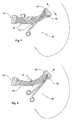
- FIG. 4is a view of the sling ( 10 ) and a standard surgical forceps ( 18 ).
- FIG. 5is a view of the sling ( 10 ) with the surgical forceps tips ( 19 ) fully extended inside one of the sling cavities ( 16 ).
- FIG. 7is a view of the sling ( 10 ) with the standard surgical forceps ( 18 ) reopening the sling cavity ( 16 ) once introduced to the body in order to increase the fibrosis surface and the sling anchorage.
- FIG. 9is a view of a preferred design of an open knot ( 22 ) for the construction of the sling ( 10 ).
- Said folded parts ( 13 a )are maintained over the other parts ( 13 b ) by means of two thermal seals ( 17 ): one sealing the upper edge and another sealing the lower edge ( 20 ) of the folded extremes ( 13 a ), as represented in FIG. 3 . Additionally, the extreme edge ( 21 ) corresponding to the axis can be also sealed. Therefore, the cavities ( 16 ) have a rectangular configuration with an opening ( 23 ) that allows the surgeon to introduce inside the surgical forceps ( 18 ).
- the geometry of the cavities ( 16 )can also adopt other similar configurations, as long as it permits the easy and correct introduction of standard surgical forceps to push and drive the sling to the proper position.
Landscapes
- Health & Medical Sciences (AREA)
- Urology & Nephrology (AREA)
- Cardiology (AREA)
- Oral & Maxillofacial Surgery (AREA)
- Transplantation (AREA)
- Engineering & Computer Science (AREA)
- Biomedical Technology (AREA)
- Heart & Thoracic Surgery (AREA)
- Vascular Medicine (AREA)
- Life Sciences & Earth Sciences (AREA)
- Animal Behavior & Ethology (AREA)
- General Health & Medical Sciences (AREA)
- Public Health (AREA)
- Veterinary Medicine (AREA)
- Prostheses (AREA)
- Surgical Instruments (AREA)
Abstract
Description
Claims (11)
Priority Applications (1)
| Application Number | Priority Date | Filing Date | Title |
|---|---|---|---|
| US11/490,136US8257245B2 (en) | 2006-07-21 | 2006-07-21 | Adjustable sling as a support of internal organs or anatomical tissues |
Applications Claiming Priority (1)
| Application Number | Priority Date | Filing Date | Title |
|---|---|---|---|
| US11/490,136US8257245B2 (en) | 2006-07-21 | 2006-07-21 | Adjustable sling as a support of internal organs or anatomical tissues |
Publications (2)
| Publication Number | Publication Date |
|---|---|
| US20080021356A1 US20080021356A1 (en) | 2008-01-24 |
| US8257245B2true US8257245B2 (en) | 2012-09-04 |
Family
ID=38972359
Family Applications (1)
| Application Number | Title | Priority Date | Filing Date |
|---|---|---|---|
| US11/490,136Expired - Fee RelatedUS8257245B2 (en) | 2006-07-21 | 2006-07-21 | Adjustable sling as a support of internal organs or anatomical tissues |
Country Status (1)
| Country | Link |
|---|---|
| US (1) | US8257245B2 (en) |
Families Citing this family (34)
| Publication number | Priority date | Publication date | Assignee | Title |
|---|---|---|---|---|
| EP2214612B1 (en) | 2007-11-21 | 2019-05-01 | Smith & Nephew PLC | Wound dressing |
| ES2715605T3 (en) | 2007-11-21 | 2019-06-05 | Smith & Nephew | Wound dressing |
| FR2931655B1 (en)* | 2008-05-29 | 2010-06-25 | Cousin Biotech | ANCHORING AND GUIDING DEVICE, METHOD FOR MANUFACTURING SUCH DEVICE AND PROTHETIC IMPLANT EQUIPPED WITH SUCH A DEVICE |
| WO2010023418A1 (en)* | 2008-09-01 | 2010-03-04 | Compagnie De Recherche En Composants, Implants Et Materiels Pour L'application Clinique | Prosthetic implant for suburethral support with rounded gusset |
| ATE551017T1 (en)* | 2008-09-01 | 2012-04-15 | Cie De Rech En Composants Implants Et Materiels Pour L Applic Clinique | PROSTHETIC IMPLANT FOR SUBURETHRAL SUPPORT WITH REINFORCEMENTS |
| WO2010049368A1 (en)* | 2008-10-30 | 2010-05-06 | Compagnie De Recherche En Composants, Implants Et Materiels Pour L'application Clinique | Kit for supporting an organ including an elongate implantable member with a reinforcement means |
| IT1399972B1 (en)* | 2010-04-19 | 2013-05-09 | Herniamesh S R L | MININVASIVE WANDER FOR THE SURGICAL TREATMENT OF FEMININE URINARY INCONTINENCE FROM EFFORT |
| US8684908B2 (en) | 2010-08-26 | 2014-04-01 | Ethicon, Inc. | Centering aid for implantable sling |
| JP6250571B2 (en) | 2012-03-12 | 2017-12-20 | スミス アンド ネフュー ピーエルシーSmith & Nephew Public Limited Company | Pressure reducing apparatus and method |
| DK3288508T3 (en) | 2015-04-27 | 2020-03-09 | Smith & Nephew | REDUCED PRESSURE DEVICES |
| EP3426206B1 (en) | 2016-03-07 | 2023-05-10 | Smith & Nephew plc | Wound treatment apparatuses and methods with negative pressure source integrated into wound dressing |
| USD801539S1 (en) | 2016-04-11 | 2017-10-31 | Coloplast A/S | Implantable support |
| USD816853S1 (en) | 2016-04-11 | 2018-05-01 | Coloplast A/S | Implantable support |
| USD816852S1 (en) | 2016-04-11 | 2018-05-01 | Coloplast A/S | Implantable support |
| USD825063S1 (en) | 2016-04-11 | 2018-08-07 | Coloplast A/S | Implantable support |
| CA3022184A1 (en) | 2016-04-26 | 2017-11-02 | Smith & Nephew Plc | Wound dressings and methods of use with integrated negative pressure source having a fluid ingress inhibition component |
| US11096831B2 (en) | 2016-05-03 | 2021-08-24 | Smith & Nephew Plc | Negative pressure wound therapy device activation and control |
| CA3038206A1 (en) | 2016-05-03 | 2017-11-09 | Smith & Nephew Plc | Optimizing power transfer to negative pressure sources in negative pressure therapy systems |
| WO2017191158A1 (en) | 2016-05-03 | 2017-11-09 | Smith & Nephew Plc | Systems and methods for driving negative pressure sources in negative pressure therapy systems |
| WO2018037075A1 (en) | 2016-08-25 | 2018-03-01 | Smith & Nephew Plc | Absorbent negative pressure wound therapy dressing |
| EP3519001B1 (en) | 2016-09-30 | 2025-05-21 | Smith & Nephew plc | Negative pressure wound treatment apparatuses and methods with integrated electronics |
| EP3551244A1 (en) | 2016-12-12 | 2019-10-16 | Smith & Nephew PLC | Pressure wound therapy status indication via external device |
| EP3592312B1 (en) | 2017-03-08 | 2024-01-10 | Smith & Nephew plc | Negative pressure wound therapy device control in presence of fault condition |
| JP7121050B2 (en) | 2017-05-09 | 2022-08-17 | スミス アンド ネフュー ピーエルシー | Redundant control of negative pressure wound therapy systems |
| GB201718070D0 (en) | 2017-11-01 | 2017-12-13 | Smith & Nephew | Negative pressure wound treatment apparatuses and methods with integrated electronics |
| CA3074780A1 (en) | 2017-09-13 | 2019-03-21 | Smith & Nephew Plc | Negative pressure wound treatment apparatuses and methods with integrated electronics |
| US11497653B2 (en) | 2017-11-01 | 2022-11-15 | Smith & Nephew Plc | Negative pressure wound treatment apparatuses and methods with integrated electronics |
| GB201718054D0 (en) | 2017-11-01 | 2017-12-13 | Smith & Nephew | Sterilization of integrated negative pressure wound treatment apparatuses and sterilization methods |
| GB201718072D0 (en) | 2017-11-01 | 2017-12-13 | Smith & Nephew | Negative pressure wound treatment apparatuses and methods with integrated electronics |
| USD898925S1 (en) | 2018-09-13 | 2020-10-13 | Smith & Nephew Plc | Medical dressing |
| USD888255S1 (en) | 2018-10-25 | 2020-06-23 | Kci Licensing, Inc. | Therapy device |
| USD884195S1 (en)* | 2018-10-25 | 2020-05-12 | Kci Licensing, Inc. | Therapy device |
| GB201903774D0 (en) | 2019-03-20 | 2019-05-01 | Smith & Nephew | Negative pressure wound treatment apparatuses and methods with integrated electronics |
| GB201907716D0 (en) | 2019-05-31 | 2019-07-17 | Smith & Nephew | Systems and methods for extending operational time of negative pressure wound treatment apparatuses |
Citations (10)
| Publication number | Priority date | Publication date | Assignee | Title |
|---|---|---|---|---|
| US6042534A (en)* | 1997-02-13 | 2000-03-28 | Scimed Life Systems, Inc. | Stabilization sling for use in minimally invasive pelvic surgery |
| US20020099260A1 (en)* | 2000-07-05 | 2002-07-25 | Patrice Suslian | Method for treating urinary incontinence in women and implantable device intended to correct urinary incontinence |
| US6612977B2 (en)* | 2001-01-23 | 2003-09-02 | American Medical Systems Inc. | Sling delivery system and method of use |
| US20040144394A1 (en)* | 2001-02-17 | 2004-07-29 | Martin Dauner | Tension-free elastic tape |
| US20050240076A1 (en)* | 2001-01-23 | 2005-10-27 | American Medical Systems | Implantable article and method |
| US20050277806A1 (en)* | 2004-06-10 | 2005-12-15 | Cristalli Bernard G R | Prosthetic implant for sub-urethral support, an instrument, an insertion kit, and a surgical method for implanting it |
| US20060089525A1 (en)* | 2004-06-14 | 2006-04-27 | Boston Scientific Scimed, Inc. | Systems, methods and devices relating to implantable supportive slings |
| US7083637B1 (en) | 1999-06-09 | 2006-08-01 | Tannhauser Robert J | Method and apparatus for adjusting flexible areal polymer implants |
| US20060195011A1 (en)* | 2005-02-04 | 2006-08-31 | Arnal Kevin R | Pelvic implants and related methods |
| US7448186B2 (en)* | 2004-07-16 | 2008-11-11 | Polyremedy, Inc. | Wound dressing and apparatus for forming same |
- 2006
- 2006-07-21USUS11/490,136patent/US8257245B2/ennot_activeExpired - Fee Related
Patent Citations (10)
| Publication number | Priority date | Publication date | Assignee | Title |
|---|---|---|---|---|
| US6042534A (en)* | 1997-02-13 | 2000-03-28 | Scimed Life Systems, Inc. | Stabilization sling for use in minimally invasive pelvic surgery |
| US7083637B1 (en) | 1999-06-09 | 2006-08-01 | Tannhauser Robert J | Method and apparatus for adjusting flexible areal polymer implants |
| US20020099260A1 (en)* | 2000-07-05 | 2002-07-25 | Patrice Suslian | Method for treating urinary incontinence in women and implantable device intended to correct urinary incontinence |
| US6612977B2 (en)* | 2001-01-23 | 2003-09-02 | American Medical Systems Inc. | Sling delivery system and method of use |
| US20050240076A1 (en)* | 2001-01-23 | 2005-10-27 | American Medical Systems | Implantable article and method |
| US20040144394A1 (en)* | 2001-02-17 | 2004-07-29 | Martin Dauner | Tension-free elastic tape |
| US20050277806A1 (en)* | 2004-06-10 | 2005-12-15 | Cristalli Bernard G R | Prosthetic implant for sub-urethral support, an instrument, an insertion kit, and a surgical method for implanting it |
| US20060089525A1 (en)* | 2004-06-14 | 2006-04-27 | Boston Scientific Scimed, Inc. | Systems, methods and devices relating to implantable supportive slings |
| US7448186B2 (en)* | 2004-07-16 | 2008-11-11 | Polyremedy, Inc. | Wound dressing and apparatus for forming same |
| US20060195011A1 (en)* | 2005-02-04 | 2006-08-31 | Arnal Kevin R | Pelvic implants and related methods |
Also Published As
| Publication number | Publication date |
|---|---|
| US20080021356A1 (en) | 2008-01-24 |
Similar Documents
| Publication | Publication Date | Title |
|---|---|---|
| US8257245B2 (en) | Adjustable sling as a support of internal organs or anatomical tissues | |
| ES2573672T3 (en) | Needle design for male sling transobturator | |
| ES2305304T3 (en) | SURGICAL INSTRUMENT KIT TO TREAT FEMALE URINARY INCONTINENCE. | |
| JP4330998B2 (en) | Surgical instruments for treating various prolapse situations of organs | |
| EP2542180B1 (en) | Minimally invasive adjustable support | |
| US8123671B2 (en) | Pelvic implant systems and methods | |
| ES2435513T3 (en) | Pelvic implant with anchor frame | |
| EP2501331B1 (en) | Implantable anatomical support | |
| US8500625B2 (en) | Surgical kit for treating urinary incontinence in man | |
| US9333064B2 (en) | Vaginal vault suspension device and method | |
| JP2010506688A (en) | Implantable device for treatment of incontinence | |
| WO2007109759A2 (en) | Female urinary incontinence treatment device and method | |
| EP2832305A1 (en) | Puncture instrument and puncture device | |
| CN101128155A (en) | Needle Design for Transobturator Slings in Males | |
| US9161829B2 (en) | Implantable medical device and methods of delivering the implantable medical device | |
| JP6490179B2 (en) | Medical devices and instruments for adjustment and cutting | |
| WO2006136625A1 (en) | Suburethral sling for the surgical treatment of female urinary incontinence and surgical instruments used to position same | |
| KR101785135B1 (en) | Minimally invasive sling for the surgical treatment of female urinary stress incontinence | |
| EP2608736B1 (en) | Centering aid for implantable sling | |
| US9168120B2 (en) | Medical device and methods of delivering the medical device | |
| ES2538279T3 (en) | Surgical anchor with high aspect ratio and method of use | |
| ES2264885B1 (en) | IMPROVEMENTS INTRODUCED IN THE PATENT OF INVENTION NP200301134, BY: SUBURETRAL HORSE FOR THE SURGICAL TREATMENT OF FEMALE URINARY INCONTINENCE. | |
| KR100849647B1 (en) | Methods and apparatus for supporting body organs, including urethra and bladder neck | |
| US20110237864A1 (en) | Prosthetic Implant For Suburethral Support With Gussets | |
| WO2007084736A1 (en) | Ratchet anchor for single incision sling |
Legal Events
| Date | Code | Title | Description |
|---|---|---|---|
| AS | Assignment | Owner name:SPECIALTIES REMEEX INTERNATIONAL, S.L., SPAIN Free format text:ASSIGNMENT OF ASSIGNORS INTEREST;ASSIGNORS:CASTELLO ESCUDE, ANTONI;FARRER VELAZQUEZ, FRANCISCO;REEL/FRAME:018238/0662 Effective date:20060904 | |
| ZAAA | Notice of allowance and fees due | Free format text:ORIGINAL CODE: NOA | |
| ZAAB | Notice of allowance mailed | Free format text:ORIGINAL CODE: MN/=. | |
| STCF | Information on status: patent grant | Free format text:PATENTED CASE | |
| FPAY | Fee payment | Year of fee payment:4 | |
| MAFP | Maintenance fee payment | Free format text:PAYMENT OF MAINTENANCE FEE, 8TH YR, SMALL ENTITY (ORIGINAL EVENT CODE: M2552); ENTITY STATUS OF PATENT OWNER: SMALL ENTITY Year of fee payment:8 | |
| FEPP | Fee payment procedure | Free format text:MAINTENANCE FEE REMINDER MAILED (ORIGINAL EVENT CODE: REM.); ENTITY STATUS OF PATENT OWNER: SMALL ENTITY | |
| LAPS | Lapse for failure to pay maintenance fees | Free format text:PATENT EXPIRED FOR FAILURE TO PAY MAINTENANCE FEES (ORIGINAL EVENT CODE: EXP.); ENTITY STATUS OF PATENT OWNER: SMALL ENTITY | |
| STCH | Information on status: patent discontinuation | Free format text:PATENT EXPIRED DUE TO NONPAYMENT OF MAINTENANCE FEES UNDER 37 CFR 1.362 | |
| FP | Lapsed due to failure to pay maintenance fee | Effective date:20240904 |