US8256732B1 - Telescoping support stand apparatus - Google Patents
Telescoping support stand apparatusDownload PDFInfo
- Publication number
- US8256732B1 US8256732B1US13/436,160US201213436160AUS8256732B1US 8256732 B1US8256732 B1US 8256732B1US 201213436160 AUS201213436160 AUS 201213436160AUS 8256732 B1US8256732 B1US 8256732B1
- Authority
- US
- United States
- Prior art keywords
- tube
- support stand
- telescoping support
- locking mechanism
- release
- Prior art date
- Legal status (The legal status is an assumption and is not a legal conclusion. Google has not performed a legal analysis and makes no representation as to the accuracy of the status listed.)
- Active
Links
Images


Classifications
- F—MECHANICAL ENGINEERING; LIGHTING; HEATING; WEAPONS; BLASTING
- F16—ENGINEERING ELEMENTS AND UNITS; GENERAL MEASURES FOR PRODUCING AND MAINTAINING EFFECTIVE FUNCTIONING OF MACHINES OR INSTALLATIONS; THERMAL INSULATION IN GENERAL
- F16B—DEVICES FOR FASTENING OR SECURING CONSTRUCTIONAL ELEMENTS OR MACHINE PARTS TOGETHER, e.g. NAILS, BOLTS, CIRCLIPS, CLAMPS, CLIPS OR WEDGES; JOINTS OR JOINTING
- F16B7/00—Connections of rods or tubes, e.g. of non-circular section, mutually, including resilient connections
- F16B7/10—Telescoping systems
- F16B7/14—Telescoping systems locking in intermediate non-discrete positions
- F16B7/1409—Telescoping systems locking in intermediate non-discrete positions with balls or rollers urged by an axial displacement of a wedge or a conical member
- F—MECHANICAL ENGINEERING; LIGHTING; HEATING; WEAPONS; BLASTING
- F16—ENGINEERING ELEMENTS AND UNITS; GENERAL MEASURES FOR PRODUCING AND MAINTAINING EFFECTIVE FUNCTIONING OF MACHINES OR INSTALLATIONS; THERMAL INSULATION IN GENERAL
- F16M—FRAMES, CASINGS OR BEDS OF ENGINES, MACHINES OR APPARATUS, NOT SPECIFIC TO ENGINES, MACHINES OR APPARATUS PROVIDED FOR ELSEWHERE; STANDS; SUPPORTS
- F16M11/00—Stands or trestles as supports for apparatus or articles placed thereon ; Stands for scientific apparatus such as gravitational force meters
- F16M11/20—Undercarriages with or without wheels
- F16M11/24—Undercarriages with or without wheels changeable in height or length of legs, also for transport only, e.g. by means of tubes screwed into each other
- F16M11/26—Undercarriages with or without wheels changeable in height or length of legs, also for transport only, e.g. by means of tubes screwed into each other by telescoping, with or without folding
- F16M11/28—Undercarriages for supports with one single telescoping pillar
- F—MECHANICAL ENGINEERING; LIGHTING; HEATING; WEAPONS; BLASTING
- F16—ENGINEERING ELEMENTS AND UNITS; GENERAL MEASURES FOR PRODUCING AND MAINTAINING EFFECTIVE FUNCTIONING OF MACHINES OR INSTALLATIONS; THERMAL INSULATION IN GENERAL
- F16M—FRAMES, CASINGS OR BEDS OF ENGINES, MACHINES OR APPARATUS, NOT SPECIFIC TO ENGINES, MACHINES OR APPARATUS PROVIDED FOR ELSEWHERE; STANDS; SUPPORTS
- F16M11/00—Stands or trestles as supports for apparatus or articles placed thereon ; Stands for scientific apparatus such as gravitational force meters
- F16M11/20—Undercarriages with or without wheels
- F16M11/24—Undercarriages with or without wheels changeable in height or length of legs, also for transport only, e.g. by means of tubes screwed into each other
- F16M11/26—Undercarriages with or without wheels changeable in height or length of legs, also for transport only, e.g. by means of tubes screwed into each other by telescoping, with or without folding
- F16M11/32—Undercarriages for supports with three or more telescoping legs
- F—MECHANICAL ENGINEERING; LIGHTING; HEATING; WEAPONS; BLASTING
- F16—ENGINEERING ELEMENTS AND UNITS; GENERAL MEASURES FOR PRODUCING AND MAINTAINING EFFECTIVE FUNCTIONING OF MACHINES OR INSTALLATIONS; THERMAL INSULATION IN GENERAL
- F16M—FRAMES, CASINGS OR BEDS OF ENGINES, MACHINES OR APPARATUS, NOT SPECIFIC TO ENGINES, MACHINES OR APPARATUS PROVIDED FOR ELSEWHERE; STANDS; SUPPORTS
- F16M2200/00—Details of stands or supports
- F16M2200/02—Locking means
- F16M2200/025—Locking means for translational movement
- F16M2200/027—Locking means for translational movement by friction
- H—ELECTRICITY
- H04—ELECTRIC COMMUNICATION TECHNIQUE
- H04R—LOUDSPEAKERS, MICROPHONES, GRAMOPHONE PICK-UPS OR LIKE ACOUSTIC ELECTROMECHANICAL TRANSDUCERS; DEAF-AID SETS; PUBLIC ADDRESS SYSTEMS
- H04R1/00—Details of transducers, loudspeakers or microphones
- H04R1/08—Mouthpieces; Microphones; Attachments therefor
- Y—GENERAL TAGGING OF NEW TECHNOLOGICAL DEVELOPMENTS; GENERAL TAGGING OF CROSS-SECTIONAL TECHNOLOGIES SPANNING OVER SEVERAL SECTIONS OF THE IPC; TECHNICAL SUBJECTS COVERED BY FORMER USPC CROSS-REFERENCE ART COLLECTIONS [XRACs] AND DIGESTS
- Y10—TECHNICAL SUBJECTS COVERED BY FORMER USPC
- Y10T—TECHNICAL SUBJECTS COVERED BY FORMER US CLASSIFICATION
- Y10T403/00—Joints and connections
- Y10T403/32—Articulated members
- Y10T403/32254—Lockable at fixed position
- Y10T403/32467—Telescoping members
- Y10T403/32516—Remotely actuated
Definitions
- Support standssuch as microphone stands and shooting stands, often include telescoping tubes that allow the height of the stands to be adjusted. These telescoping stands may have an inner tube, an outer tube, and a lock that keeps the inner tube from sliding relative to the outer tube. Such stands may be used in situations that require the stands to be rugged and capable of withstanding the elements. For example, hunter's shooting stands, microphone stands, telescope stands, and camera stands are often used outdoors. The components of a stand intended for outdoor use may need to be sealed and tightly fitted to keep water, dirt, and other debris from getting inside the tubes of the stand.
- a usermay adjust the height of a telescoping support stand by releasing the lock and moving the inner tube up and down within the outer tube.
- the lockmay be a collar that is rotatable to compress the inner tube and the outer tube, binding them at a set length.
- the lockmay also be a set screw bolt that passes through the outer tube and presses against the inner tube.
- One problem with these types of locksis the time it takes for a user to turn the collar or bolt when making a height adjustment to the stand.
- Another problem with these locksis that the user may have to hold the inner tube in position while fastening the lock, thus requiring the use of two hands.
- Some support standsare equipped with an external trigger connected to an internal lock that secures the inner tube to the outer tube.
- This locking configurationmay allow a user to make quick height adjustments and may permit the user to make adjustments using only one hand.
- the external triggermay be placed on a handle attached to the top of the inner tube. While there are many benefits to a quick-adjustment configuration that utilizes an internal locking mechanism and a handle trigger, there are numerous problems associated with such a support stand configuration.
- an internal lockmay restrict the flow of air between the inner and outer tubes.
- the internal lockmay be sized to fit snugly within the inner tube and press securely against the outer tube, which closes off the air passageway between the inner and outer tubes.
- support standsare often manufactured to keep water and other debris out, which prevents air from freely flowing in and out of the stand. Thus, air cannot easily flow into, out of, or between the tubes of rugged support stands with internal locks.
- a usermay need to use two hands to overcome the vacuum and dampening effects to adjust the height of the stand. For example, users may hold the inner tube with one hand while pulling down on the outer tube with the other hand. Users may also hold the outer tube between their feet while pulling up on the inner tube. This situation is undesirable when the user needs to make a quick adjustment or does not have a free hand to help make the adjustment.
- Another problem with the quick-adjustment stand configurationis that a user may inadvertently pull the trigger while gripping the handle.
- a hunter targeting a moving bull elkmay keep one hand on the handle of a shooting stand to be ready to make height adjustments.
- the huntermay accidentally activate the trigger on the stand, which would drop the height of the stand as he shoots. This situation is dangerous and could result in an inaccurate shot.
- a telescoping support standmay comprise a first tube partially defining a first enclosed area and a second tube partially defining a second enclosed area, a first end of the second tube being telescopically slidable within the first tube.
- the telescoping support standmay also comprise a first locking mechanism attached to the second tube, the first locking mechanism releasably securing the first tube to the second tube to prevent longitudinal movement of the first tube relative to the second tube.
- the telescoping support standmay further comprise a first air exchange aperture dimensioned to allow air to flow between the first and second enclosed areas.
- the first air exchange aperturemay comprise an opening in the first locking mechanism.
- the first air exchange aperturemay comprise a gap between the first locking mechanism and the first tube.
- the first air exchange aperturemay comprise a notch in the first locking mechanism.
- the telescoping support standmay also comprise a second air exchange aperture dimensioned to allow air to exit the second tube.
- the second air exchange aperturemay comprise an opening in the second tube.
- the telescoping support standmay include a head attached to a second end of the first tube, and the second air exchange aperture may allow air to flow from the second tube into the head.
- the telescoping support standmay include a third air exchange aperture dimensioned to allow air to exit the head.
- the first locking mechanismmay comprise a truncated-cone member attached to the first end of the second tube and a bearing assembly comprising a bearing retainer and a plurality of bearings.
- the bearing retainermay comprise an opening for receiving the truncated-cone member, and the bearing assembly may be movable between first and second positions relative to the truncated-cone member.
- the truncated-cone membermay be dimensioned to press the bearings against an interior surface of the first tube while in the first position, and the truncated-cone member may be dimension to allow the bearings to move away from the interior surface of the first tube while in the second position.
- the truncated-cone membermay partially define the first air exchange aperture.
- the bearing assemblymay at least partially define the first air exchange aperture, and the first locking mechanism may partially define each of the first and second enclosed areas.
- the telescoping support standmay comprise a release mechanism attached to a second end of the second tube.
- the release mechanismmay be movable to release the first locking mechanism to allow longitudinal movement of the first tube relative to the second tube.
- the release mechanismmay comprise a handle attached to the second end of the second tube, the handle comprising an outside surface.
- the telescoping support standmay also comprise a trigger attached to the handle, the trigger comprising an inside surface positioned opposite the outside surface of the handle, the trigger being dimensioned to allow a user to hold the handle by placing a portion of a hand between the outside surface of the handle and the inside surface of the trigger, the trigger being movable to release the first locking mechanism to allow longitudinal movement of the first tube relative to the second tube.
- the telescoping support standmay comprise a release rod attached to the first locking mechanism, and the first air exchange aperture may comprise an opening in the release rod.
- the telescoping support standmay also comprise a release mechanism movable to cause the release rod to release the first locking mechanism and allow longitudinal movement of the first tube relative to the second tube.
- the telescoping support standmay comprise a third tube partially defining a third enclosed area, a first end of the third tube being telescopically slidable within the second tube.
- the telescoping support standmay also comprise a second locking mechanism attached to the third tube, the second locking mechanism releasably securing the second tube to the third tube to prevent longitudinal movement of the second tube relative to the third tube.
- the telescoping support standmay include a second air exchange aperture dimensioned to allow air to flow between the second and third enclosed areas.
- the telescoping support standmay comprise a first leg comprising the first and second tubes and a second leg attached to the first leg, the second leg comprising third and fourth tubes.
- the telescoping support standmay comprise a head attached to the first tube, the head being adapted to attach to at least one of: a microphone clip, a camera, a telescope, a spotting scope, binoculars, a surveyor level, and/or a gun rest.
- the gun restmay be attached to a second end of the second tube.
- the first air exchange aperturemay extend between the first and second enclosed areas.
- the first locking mechanismmay be released by pulling the first tube away from the second tube.
- a telescoping support standmay comprise a first tube partially defining a first enclosed area, a second tube partially defining a second enclosed area, a first end of the second tube being telescopically slidable within the first tube, a first air exchange aperture dimensioned to allow air to exit the second tube, a locking mechanism attached to the second tube, the locking mechanism releasably securing the first tube to the second tube to prevent longitudinal movement of the first tube relative to the second tube, and a second air exchange aperture dimensioned to allow air to flow between the first and second enclosed areas.
- the second tubeat least partially defines the first air exchange aperture and the locking mechanism at least partially defines the second air exchange aperture.
- the second air exchange aperturecomprises at least one of: an opening in the locking mechanism, a notch in the locking mechanism, a gap between the locking mechanism and an interior surface of the first tube, and a gap between the locking mechanism and a release rod.
- the telescoping support standmay comprise a release rod attached to the locking mechanism, wherein the second aperture comprises an opening in the release rod.
- the telescoping support standmay also comprise a release mechanism in contact with the release rod, the release mechanism being movable to cause the release rod to release the locking mechanism and allow longitudinal movement of the first tube relative to the second tube.
- the telescoping support standmay further comprise an attachment member connecting the release rod to the release mechanism, wherein the first aperture comprises an opening in the attachment member.
- the locking mechanismmay be adapted to releasably secure the first tube to the second tube by pressing against an inside surface of the first tube.
- the telescoping support standmay also comprise an end cap attached to the first tube, wherein the end cap, the first tube, and the locking mechanism define the first enclosed area.
- the telescoping support standmay also comprise a head attached to the second tube, wherein the head, the second tube, and the locking mechanism define the second enclosed area.
- a telescoping support standmay comprise a leg comprising first and second tubes, a locking mechanism adapted to prevent longitudinal movement of the first tube relative to the second tube, a handle attached to the leg, the handle comprising an outside surface.
- the telescoping support standmay also comprise a trigger attached to the handle, the trigger having an inside surface positioned opposite the outside surface of the handle.
- the triggermay be dimensioned to allow a user to hold the handle by placing a portion of a hand between the outside surface of the handle and the inside surface of the trigger, and the trigger may be movable to release the locking mechanism to allow longitudinal movement of the first tube relative to the second tube.
- a first end of the second tubeis telescopically slidable within the first tube and the handle is attached to a second end of the second tube.
- the telescoping support standmay further comprise a locking mechanism attached to the second tube, the locking mechanism being responsive to the trigger to releasably secure the first tube to the second tube to prevent longitudinal movement of the first tube relative to the second tube.
- the locking mechanism, the second tube, and the handlemay define a first enclosed area.
- the telescoping support standmay also comprise an end cap attached to the first tube, wherein the end cap, the first tube, and the locking mechanism define a second enclosed area.
- the telescoping support standcomprises a first air exchange aperture dimensioned to allow air to flow between the first and second enclosed areas.
- the telescoping support standfurther comprises a second air exchange aperture dimensioned to allow air flow from the first enclosed area to the handle.
- the telescoping support standmay also include a third air exchange aperture dimensioned to allow air to exit the handle.
- the telescoping support standcomprises a gun rest attached to the handle.
- a method of assembling a telescoping support standcomprises providing a first tube and providing a second tube comprising first and second ends, the first end of the second tube being telescopically slidable within the first tube.
- the first tubemay partially define a first enclosed area and the second tube may partially define a second enclosed area.
- the methodmay also comprise providing a locking mechanism dimensioned to allow air to flow between the first and second enclosed areas.
- the methodmay further comprise attaching the locking mechanism to the second tube at the first end, the locking mechanism being adapted to releasably secure the first tube to the second tube to prevent longitudinal movement of the first tube relative to the second tube.
- the methodmay comprise attaching a release mechanism to the second tube at the second end, the release mechanism being movable to release the locking mechanism to allow longitudinal movement of the first tube relative to the second tube.
- the methodmay also comprise sliding the second tube into the first tube.
- a telescoping support standmay comprise a first tube and a second tube. A first end of the second tube may be telescopically slidable within the first tube.
- the telescoping support standmay also include a truncated cone extending from the first end of the second tube, a top portion of the truncated cone having a larger diameter than a bottom portion of the truncated cone.
- the telescoping support standcomprises a bearing assembly with bearings.
- the bearing assemblymay be disposed around at least a portion of the truncated cone such that the bearing assembly is movable between first and second positions relative to the truncated cone, the top portion of the truncated cone pushing the bearings against an inside surface of the first tube when the bearing assembly is in the first position, the bottom portion of the truncated cone allowing the bearings to move away from the interior surface of the first tube when the bearing assembly is in the second position.
- a telescoping support standmay comprise a leg with first and second tubes, a locking mechanism adapted to prevent longitudinal movement of the first tube relative to the second tube, a trigger coupled to the locking mechanism, and a spring connected to the trigger to bias the trigger in a first position.
- a telescoping support standmay comprise a first tube partially defining a first enclosed area, a second tube partially defining a second enclosed area, and a third tube partially defining a third enclosed area.
- a first end of the first tubemay be telescopically slidable within the second tube, and a first end of the second tube may be telescopically slidable within the third tube.
- a first locking mechanismmay be attached to the first tube, and the first locking mechanism may releasably secure the first tube to the second tube to prevent longitudinal movement of the second tube relative to the first tube.
- a second locking mechanismmay be attached to the second tube, and the second locking mechanism may releasably secure the first tube to the second tube to prevent the second tube from collapsing into the third tube.
- the second locking mechanismmay allow the second tube to be pulled to an expanded position relative to the third tube.
- a first air exchange aperturemay allow air to flow between the first and second enclosed areas, and a second air exchange aperture may allow air to flow between the second and third enclosed areas.
- the telescoping support standmay further comprise a release rod attached to the first locking mechanism.
- a bottom portion of the first locking mechanismmay be dimensioned to release the second locking mechanism.
- a telescoping support standmay comprise two or more extendable legs, at least one of the extendable legs comprising a first tube, a first enclosed area being at least partially defined within the first tube. Additionally, at least one of the extendable legs may comprise a second tube, a first end of the second tube being telescopically slidable within the first tube, wherein a second enclosed area is at least partially defined within the second tube. At least one of the extendable legs may also comprise a first locking mechanism attached to the second tube, the first locking mechanism releasably securing the first tube to the second tube to prevent longitudinal movement of the first tube relative to the second tube. At least one of the extendable legs may additionally comprise a first air exchange aperture dimensioned to allow air to flow between the first and second enclosed areas.
- a telescoping support standmay comprise two or more extendable legs, each of the two or more extendable legs comprising a first tube and a corresponding second tube, the first tube in each of the two or more extendable legs being telescopically slidable within the corresponding second tube.
- Each of the two or more extendable legsmay additionally comprise a locking mechanism in each of the two or more extendable legs, each of the locking mechanisms being adapted to prevent longitudinal movement of the first tube relative to the second corresponding tube.
- Each of the two or more extendable legsmay also comprise a release mechanism coupled to the two or more extendable legs, the release mechanism being configured to release the locking mechanism in each of the two or more extendable legs to allow longitudinal movement of the first tube relative to the corresponding second tube in each of the two or more extendable legs.
- a method of assembling a telescoping support standmay comprise providing two or more extendable legs, at least one of the extendable legs comprising a first tube, a first enclosed area being at least partially defined within the first tube. Additionally, at least one of the extendable legs may comprise a second tube comprising first and second ends, the first end of the second tube being telescopically slidable within the first tube, wherein a second enclosed area is at least partially defined within the second tube. The method may further comprise providing a locking mechanism in each of the extendable legs, the locking mechanism being dimensioned to allow air to flow between the first and second enclosed areas.
- the methodmay additionally comprise attaching the locking mechanism to the second tube at the first end, the locking mechanism being adapted to releasably secure the first tube to the second tube to prevent longitudinal movement of the first tube relative to the second tube.
- the methodmay also comprise attaching a release mechanism to the second tube at the second end, the release mechanism being movable to release the locking mechanism to allow longitudinal movement of the first tube relative to the second tube.
- the methodmay comprise sliding the second tube into the first tube.
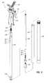
- FIG. 1is a perspective view of an exemplary telescoping support stand according to certain embodiments.
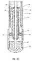
- FIG. 2Ais a cross-sectional side view of the telescoping support stand illustrated in FIG. 1 according to certain embodiments.
- FIG. 2Bis a cross-sectional side view of the telescoping support stand illustrated in FIG. 1 according to certain embodiments.
- FIG. 2Cis a cross-sectional side view of the telescoping support stand illustrated in FIG. 1 according to certain embodiments.
- FIG. 3Ais a cross-sectional side view of the telescoping support stand illustrated in FIG. 1 in an extended position according to certain embodiments.
- FIG. 3Bis a perspective cross-sectional view of a handle of a telescoping support stand according to certain embodiments.
- FIG. 3Cis a perspective cross-sectional view of a locking mechanism of a telescoping support stand according to certain embodiments.
- FIG. 4is an exploded perspective view of the telescoping support stand illustrated in FIG. 1 according to certain embodiments.
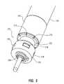
- FIG. 5is a perspective view of an exemplary locking mechanism attached to an inner tube according to certain embodiments.
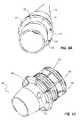
- FIG. 6Ais a perspective view of a truncated-cone member of the locking mechanism illustrated in FIG. 5 according to certain embodiments.
- FIG. 6Bis a perspective view of a truncated-cone member according to certain embodiments.
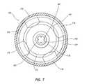
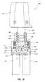
- FIG. 7is a cross-sectional top view of an exemplary locking mechanism according to certain embodiments.
- FIG. 8is another cross-sectional top view of an exemplary locking mechanism according to certain embodiments.
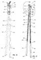
- FIG. 9is an exploded side view of an exemplary telescoping support stand according to certain embodiments.
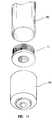
- FIG. 10is a perspective view of an exemplary crown nut according to certain embodiments.
- FIG. 11is a side view of an exemplary handle of a telescoping support stand according to certain embodiments.
- FIG. 12is a perspective view of an exemplary telescoping support stand with three legs according to certain embodiments.
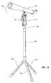
- FIG. 13is a perspective view of an exemplary telescoping support stand with a tripod base according to certain embodiments.
- FIG. 14Ais a perspective view of an exemplary bipod telescoping support stand according to certain embodiments.
- FIG. 14Bis a perspective view of the exemplary bipod telescoping support stand illustrated in FIG. 14A .
- FIG. 15is a cross-sectional side view of an exemplary telescoping support stand with three tubes according to certain embodiments.
- FIG. 16is a cross-sectional side view of the telescoping support stand of FIG. 15 according to certain embodiments.
- FIG. 17is a cross-sectional side view of the telescoping support stand of FIG. 15 according to certain embodiments.
- FIG. 18is a cross-sectional side view of the telescoping support stand of FIG. 15 according to certain embodiments.
- FIG. 19is a perspective view of a bottom portion of a telescoping support stand according to certain embodiments.
- FIG. 20is a perspective view of a telescoping support stand according to certain embodiments.
- FIG. 21is a cross-sectional perspective view of a telescoping support stand according to certain embodiments.
- FIG. 22is a cross-sectional side view of a top portion of a telescoping support stand according to certain embodiments.
- FIG. 23is a cross-sectional side view of the top portion of a telescoping support stand according to certain embodiments.
- FIG. 24is a cross-sectional side view of the top portion of a telescoping support stand according to certain embodiments.
- FIG. 25is a cut-away perspective view of a connection housing of a telescoping support stand according to certain embodiments.
- FIG. 26is a perspective view of a telescoping support stand according to certain embodiments.
- FIG. 27is a perspective view of a telescoping support stand according to certain embodiments.
- FIG. 28is a cross-sectional side view of a top portion of a telescoping support stand according to certain embodiments.
- FIG. 29is a cut-away side view of a connection housing of a telescoping support stand according to certain embodiments.
- FIG. 1is a perspective view of a telescoping support stand according to some embodiments.
- Telescoping support stand 100may include an outer tube 140 and an inner tube 150 , and inner tube 150 may be telescopically slidable within outer tube 140 .
- Inner tube 150may have a smaller diameter than outer tube 140 , which may allow inner tube 150 to be telescopically slidable within outer tube 140 .
- Inner tube 150 and outer tube 140may be referred to as a leg of telescoping support stand 100 .
- outer tube 140 and inner tube 150may be cylindrical elongate tubes.
- outer tube 140 and inner tube 150may be any shape of elongate tube.
- inner tube 150 and outer tube 140may be rectangular, elliptical, or triangular elongate tubes.
- Outer tube 140 and inner tube 150may be formed of any type or combination of materials, such as metal (e.g., aluminum or stainless steel), plastic, wood, or any other suitable material.
- Inner tube 150 and outer tube 140may also be various lengths.
- Inner tube 150may be connected to a head, such as a handle 110 , as shown in FIG. 1 .
- handle 110may be attached to outer tube 140 instead of being attached to inner tube 150 .
- Handle 110may include a release mechanism, such as a trigger 120 .
- a release mechanismmay also be a button or other any other device capable of actuating a locking mechanism.
- trigger 120is shown in FIG. 1 to be attached to handle 110
- trigger 120may also be attached to other portions of telescoping support stand 100 .
- trigger 120may be attached directly to inner tube 150 or to outer tube 140 .
- Handle 110 and trigger 120may also be formed of any suitable material, including metal, plastic, or wood.
- Trigger 120may be connected to a locking mechanism.
- the locking mechanismmay releasably secure outer tube 140 to inner tube 150 to prevent longitudinal movement of inner tube 150 relative to outer tube 140 .
- FIGS. 2-9discuss exemplary locking mechanisms according to various embodiments.
- Handle 110may be attached to an accessory, such as a gun rest 130 , as shown in FIG. 1 .
- Handle 110may also be attached to other types of accessories, which may include gun mounts, microphone clips, cameras, camcorders, professional photography equipment, telescopes, surveyors' equipment, and any other type of equipment, accessory, or attachment capable of being attached to handle 110 .
- the headitself may comprise an accessory (e.g., a camera, a gun mount, a telescope, a microphone clip, etc.) or any other type of attachment.
- gun rest 130may be v-shaped. Gun rest 130 may also be various other shapes. In various embodiments, gun rest 130 may be rotatable. Gun rest 130 may be shaped to allow a shooter to rest a barrel or other portion of a gun in gun rest 130 to help stabilize the gun while the shooter is shooting.
- telescoping support stand 100may include a gun mount instead of a gun rest. Gun rest 130 (or any other accessory or head) may include a hook that allows telescoping support stand 100 to be attached to clothing, a belt, or a pack for easy carrying.
- FIGS. 2-10discuss, among other things, an air-exchange system for a telescoping support stand.
- the discussion corresponding to FIG. 11focuses on an extended trigger feature of a telescoping support stand, and FIGS. 12-19 illustrate additional exemplary telescoping support stands and features.
- FIG. 2Ais a cross-sectional side view of the exemplary telescoping support stand of FIG. 1 .
- FIG. 2Aillustrates three enclosed areas inside telescoping support stand 100 , enclosed area 180 , enclosed area 185 , and enclosed area 190 .
- Enclosed area 180may be partially or completely within inner tube 150 .
- enclosed area 180may be enclosed on the sides by inner tube 150 , on the top by a release rod guide 152 , and on the bottom by a locking mechanism 170 .
- Enclosed area 180may also be enclosed on the top by handle 110 .
- enclosed area 180may be enclosed at the top by a head, a gun rest, or any other type of accessory.
- Enclosed area 185may be partially or completely within handle 110 .
- enclosed area 185is the empty space within handle 110 .
- the top end of enclosed area 180is not sealed, and enclosed area 180 may open up into enclosed area 185 .
- Enclosed area 190may be partially or completely enclosed within outer tube 140 .
- Enclosed area 190may be enclosed on the sides by outer tube 140 , on the bottom by an end cap 144 , and on the top by locking mechanism 170 . Instead of being enclosed by end cap 144 , in some embodiments enclosed area 190 may be enclosed by outer tube 140 at the bottom.
- Enclosed areas 180 and 190may be completely or substantially air-tight.
- end cap 144may be sealed or attached to outer tube 140 such that little or no air can escape from enclosed area 190 through or around end cap 144 .
- Release rod guide 160may be secured at the top end of inner tube 150 such that little or no air can escape through the top of inner tube 150 .
- vacuum and dampening effectsslow the ability of telescoping support stand 100 to move between collapsed and expanded positions.
- the bottom of enclosed area 190 and the top of enclosed area 180may be referred to as substantially air-tight when, without any type of air exchange system, dampening and vacuum affects are present when the telescoping support stand is adjusted.
- locking mechanism 170may divide enclosed area 180 from enclosed area 190 .
- locking mechanism 170may be attached to an end of inner tube 150 , as shown in FIG. 2A .
- Locking mechanism 170may also be disposed within inner tube 150 at a location other than an end of inner tube 150 .
- inner tube 150may include openings that allow portions of locking mechanism 170 to extend through inner tube 150 and contact outer tube 140 .
- Locking mechanism 170may be able to releasably secure inner tube 150 to outer tube 140 by pressing against an inside surface of outer tube 140 .
- locking mechanism 170may be attached to outer tube 140 .
- FIG. 2Aalso illustrates additional features of handle 110 .
- the trigger 120includes an inner curved, sloped or contoured inner surface which, in combination with handle 110 , defines an open area for a person's hand, finger, or fingers.
- Handle 110may include an accessory attachment member 112 .
- Accessory attachment member 112may include a threaded member for securing handle 110 to an attachment, such as gun rest 130 .
- Accessory attachment member 112may be rotated to screw a threaded member into an attachment.
- Handle 110may also include an adjustment member 122 attached to trigger 120 .
- Adjustment member 122may allow a user to adjust the spacing between adjustment member 122 and a release rod 160 . For example, if there is play in trigger 120 (e.g., there is a gap between adjustment member 122 and release rod 160 ) adjustment member 122 may be moved to take the play out of trigger 120 .
- release rod 160may be attached to locking mechanism 170 .
- release rod 160may couple locking mechanism 170 to trigger 120 , releasing locking mechanism 170 when trigger 120 is pulled toward handle 110 .
- the height of telescoping support stand 100may be adjusted while trigger 120 is pulled.
- locking mechanism 170may secure inner tube 150 to outer tube 140 and prevent further height adjustment of telescoping support stand 100 .
- FIG. 2Aalso shows an end cap 142 below handle 110 .
- End cap 142may be attached to a top end of outer tube 140 and may serve multiple purposes. For example, end cap 142 may prevent inner tube 150 from being completely separated or pulled from outer tube 140 . End cap 142 may also serve to substantially seal outer tube 140 to inner tube 150 to prevent water, dirt, or debris from entering outer tube 140 , thus substantially preventing air from entering or exiting outer tube 140 through or around end cap 142 .
- FIG. 2Bis a cross-sectional diagram of handle 110 .
- inner tube 150may include openings 151 and 153 .
- Opening 151may be an air exchange aperture that allows air to flow between enclosed area 180 and enclosed area 185 .
- Openings 153may receive pegs extending from handle 110 , allowing handle 110 to hold inner tube 150 in place.
- Handle 110may also include an opening 121 .
- Opening 121may be under and/or above trigger 120 . In some embodiments, opening 121 may also extend around the sides of trigger 120 .
- Opening 121may be an air exchange aperture allowing air to enter and exit enclosed area 185 (and thereby allowing air to enter an exit telescoping support stand 100 .)
- FIG. 2Balso shows that adjustment member 122 may include a wedge-shaped member 124 .
- wedge-shaped member 124When adjustment member 122 is turned counter-clockwise, wedge-shaped member 124 may move to the right and may take up slack between wedge-shaped member and release rod 160 .
- wedge-shaped member 124When adjustment member 122 is turned clockwise, wedge-shaped member 124 may move to the left and reduce pressure on release rod 160 .
- FIG. 2Cis a cross-sectional diagram of a bottom portion of telescoping shooting stand 100 .
- locking mechanism 170may include a truncated-cone member 172 , a bearing retainer 174 , bearings 176 , a tubular member 178 , and a spring 179 .
- FIG. 2Calso shows end cap 144 and an accessory attachment member 146 .
- FIG. 3Ais a cross-sectional diagram of telescoping support stand 100 in an extended position.
- trigger 120may be pulled towards handle 110 to release locking mechanism 170 and allow outer tube 140 to slide longitudinally relative to inner tube 150 .
- the volume of enclosed area 190may increase substantially when telescoping support stand 100 is extended. If enclosed area 190 is substantially air-tight, air will not be able to quickly enter enclosed area 190 when outer tube 140 is moved to an extended position. Even if some air is able to enter enclosed area 190 around end cap 144 or through locking mechanism 170 , a vacuum effect may slow or inhibit movement of outer tube 140 to an extended position if air is not able to quickly enter and exit enclosed area 190 .
- telescoping support stand 100may include air exchange apertures that allow air to enter and exit enclosed area 190 , thereby reducing or eliminating the vacuum and dampening affects caused when enclosed area 190 is substantially sealed.
- FIG. 3Ashows an air-flow path F, which illustrates air flow through air exchange apertures when outer tube 140 is being moved to an extended position.
- air-flow path Fillustrates an example of how air may flow through air exchange apertures when the height of telescoping support stand 100 is increased.
- the first air exchange aperturemay be an opening or other air inlet in handle 110 .
- the second air exchange aperturemay be an opening in inner tube 150 or an opening in or around release rod guide 152 .
- the third air exchange aperturemay be an opening in, around, or through locking mechanism 170 .
- the first, second, and third air exchange aperturesmay serve to reduce or eliminate the vacuum effect caused when telescoping support stand 100 is substantially air-tight, and outer tube 140 may be able to move quickly (i.e., approximately one or two seconds or less, as compared to several seconds) to an extended position relative to inner tube 150 .
- the vacuum effectmay also be reduced by including only one or two of the first, second, and third air exchange apertures in telescoping support stand 100 .
- more than three air exchange aperturesmay be included in telescoping support stand 100 .
- the first, second, and third air exchange aperturesmay serve to reduce or eliminate the dampening effect caused when telescoping support stand 100 is substantially air-tight, and telescoping support stand 100 may be able to be quickly moved to a collapsed position.
- the dampening effectmay also be reduced by including only one or two of the first, second, and third air exchange apertures in telescoping support stand 100 .
- FIG. 3Bis a perspective cross-sectional view of handle 100 , and illustrates exemplary first and second air exchange apertures. Opening 128 , which may allow air to flow around trigger 120 and enter enclosed area 185 , may be the first air exchange aperture. Opening 151 , which may allow air to flow between enclosed areas 180 and 185 , may be the second air exchange aperture. Handle 110 may also include other air exchange apertures in addition to or instead of opening 128 .
- FIG. 3Balso illustrates another embodiment of trigger 120 . Instead of having wedge-shaped member 124 , trigger 120 may include a lower portion 128 that contacts release rod 160 directly. A spring 126 may be provided to bias trigger 120 in a first upward position and eliminate play in trigger 120 . Thus, spring 126 may reduce or eliminate the need for adjustment member 122 .
- FIG. 3Cis a perspective cross-sectional view of locking mechanism 170 with air exchange apertures that allow air to flow between enclosed area 180 and enclosed area 190 .
- a gap 183which is between an upper portion tubular member 178 and inner tube 150 , may allow air to flow past the upper portion of tubular member 178 .
- Notches 173 in truncated cone member 172may allow air to flow past truncated cone member 172 .
- Notches 173are also shown in FIGS. 4 , 5 , 6 A, and 6 B.
- a gap 177which is between bearing retainer 174 and outer tube 140 , may allow air to flow past bearing retainer 140 and into enclosed area 190 .
- airmay flow through gap 183 , notches 173 , and gap 177 .
- FIGS. 3A , 3 B, and 3 Cshow air flow in a downward direction (the direction air flows when telescoping support stand 100 is being extended), those of skill in the art will appreciate that air may also flow in the opposite (upward) direction through the air exchange apertures illustrated in FIGS. 3A , 3 B, and 3 C. Air may flow in an upward direction when telescoping support stand 100 is being collapsed.
- FIGS. 4-10illustrate various embodiments of air exchange apertures that may be included in telescoping support stands. According to certain embodiments, one of the air exchange apertures illustrated in FIGS. 4-10 may be included in a telescoping support stand without including any other air exchange apertures in the telescoping support stand. In some embodiments, any or all of the air exchange apertures illustrated in FIGS. 4-10 may be included together in a telescoping support stand.
- FIG. 4is an exploded perspective view of telescoping support stand 100 .
- handle 110may be divided into a handle section 114 and a handle section 116 .
- Handle sections 114 and 116may be shaped to fit together to hold release rod guide 152 , trigger 120 , and accessory attachment member 112 .
- Release rod guide 152may be attached to a top end of inner tube 150 and may include an opening through which release rod 160 may pass. In some embodiments, release rod guide 152 may fit snugly within inner tube 150 and snugly around release rod 160 , substantially preventing air from passing through the top end of inner tube 150 .
- release rod guide 152may at least partially define air exchange apertures that allow air to enter and exit enclosed area 180 through or around release rod guide 152 .
- release rod guide 152may be dimensioned to allow air to pass between release rod guide 152 and release rod 160 , providing an air exchange aperture between release rod guide 152 and release rod 160 (i.e., an air exchange aperture partially defined by release rod guide 152 and partially defined by release rod 160 ).
- Release rod guide 152may also include air exchange openings extending between enclosed area 180 and an area enclosed by handle 110 .
- release rod guide 152may also function as a silencer, reducing noise from the movement of internal parts of telescoping support stand 100 .
- Inner tube 150may include air exchange apertures.
- opening 151may be an air exchange aperture that allows air to enter and exit enclosed area 180 .
- opening 151may be a circular opening in inner tube 150 .
- Opening 151may also be any other shape or size of air exchange aperture in inner tube 150 .
- Inner tube 150may also include additional openings 153 .
- Openings 153may receive pegs extending from handle sections 114 and 116 to secure handle sections 114 and 116 to inner tube 150 . In certain embodiments, openings 153 may be large enough to allow air to pass between the posts and inner tube 150 .
- FIG. 4also illustrates an exploded view of an exemplary locking mechanism 170 .
- locking mechanism 170may include truncated-cone member 172 , bearing retainer 174 , bearings 176 , tubular member 178 , and spring 179 .
- Tubular member 178may be a cylinder with a an opening through the middle. As shown in FIG. 4 , the opening may receive release rod 160 .
- tubular member 178may be attached to release rod 178 so that tubular member 178 will move when release rod 160 moves.
- Bearing retainer 174may hold bearings 176 in place and may be attached to tubular member 178 .
- Truncated-cone member 172may be disposed around tubular member 178 such that a tapered portion of truncated-cone member 172 comes into contact with bearings 176 .
- a top portion of truncated-cone member 172may be threaded to allow truncated-cone member 172 to attach to inner tube 150 .
- release rod 160moves tubular member 178 and bearing retainer 174 in a downward direction
- truncated-cone member 172may stay stationary relative to tubular member 178 and bearing retainer 174 .
- Spring 179may be positioned on top of or within truncated-cone member 172 and may bias tubular member 178 and bearing retainer 174 in a first position. In the first position, bearing retainer 174 holds bearings 176 against a top section of the tapered portion of truncated-cone member 172 such that truncated cone member 172 presses bearings 176 against an inside surface of outer tube 140 . Thus, when bearing retainer 174 is in the first position, bearings 160 may prevent longitudinal movement of outer tube 140 relative to inner tube 150 .
- release rod 160may press tubular member 178 and bearing retainer 174 downward to a second position.
- a lower portion of the tapered section of truncated-cone member 172allows bearings 176 to move away from the inside surface of outer tube 140 .
- bearings 176may not be forced against the inside surface of outer tube 140 , allowing longitudinal movement of outer tube 140 relative to inner tube 150 .
- bearing retainer 174may be secured to inner tube 150
- truncated-cone member 172may be attached to release rod 160 .
- the tapered portion of truncated-cone member 172may be pointed towards handle 110 .
- Trigger 120may move truncated-cone member 172 in a downward direction to release bearings 176 and allow longitudinal movement of outer tube 140 .
- bearing retainer 174may contain any number of bearings.
- bearing retainer 174may include three or four bearings.
- bearing retainer 174may include just one or two bearings or many more than four bearings.
- bearings 176are made of metal.
- bearings 176are made of plastic, rubber, or any other suitable material.
- various types of locking mechanismsfall within the scope of embodiments described herein.
- locking mechanism 170may include detents that can be pressed into notches in the inside surface of outer tube 140 . The description of FIG. 9 also mentions other types of locking mechanisms.
- FIGS. 5-8illustrate various air exchange apertures within locking mechanism 170 .
- FIG. 5is a perspective view of locking mechanism 170 attached to inner tube 150 .
- FIG. 5shows bearing retainer 174 in the first position relative to truncated-cone member 172 . In the first position, bearings 176 are pushed outward such that they protrude from bearing retainer 174 . Accordingly, bearings 176 may press against the inside surface of outer tube 140 to secure outer tube 140 to inner tube 150 .
- FIG. 5also illustrates that truncated-cone member 172 may include notches 173 . As previously mentioned, notches 173 may be air exchange apertures that allow air to pass between inner tube 150 and outer tube 140 . In certain embodiments, notches 173 may extend between enclosed area 180 and enclosed area 190 .
- locking mechanism 170may help to keep locking mechanism 170 from slipping under a load.
- the loadmay push inner tube 150 in a downward direction.
- Locking mechanism 170in a locked position, keeps inner tube 150 from sliding down into outer tube 140 .
- the locking mechanismsmay start to slip if too much downward force is applied to gun rest 130 .
- locking mechanism 170may actually fasten more securely under a load. This is because downward pressure on inner tube 150 may force truncated-cone member 172 , which may be attached to a bottom end of inner tube 150 , further into bearing retainer 174 .
- Truncated-cone member 172When truncated-cone member 172 is forced further into bearing retainer 174 , truncated cone-member 172 causes bearings 176 to press more firmly against the inside surface of outer tube 140 . Truncated-cone member 172 , particularly when under a load, may apply a rotational force to bearings 176 in a direction opposite to the direction that bearings 176 rotate when moving downward through outer tube 140 . This rotational force may also help to keep bearing-member 170 from slipping under a load.
- FIG. 6Ais a perspective view of truncated-cone member 172 of locking mechanism 170 .
- notches 173may partially define air exchange apertures that allow air to flow in and out of inner tube 150 .
- Inner tube 150may also partially define these air exchange apertures.
- truncated-cone member 172may include openings 181 in addition to or instead of notches 173 . While openings 181 are shown as circular openings, in certain embodiments, openings 181 may include slits, holes, pinholes, channels, or any other type of apertures that will allow air to flow between enclosed areas 180 and 190 through truncated-cone member 172 . Openings 181 may also be included in any portion of truncated-cone member 172 , including the tapered portion.
- FIG. 7is a cross-sectional view of locking mechanism 170 in the first position.
- FIG. 7shows truncated-cone member 172 may press bearings 176 against an inside surface of outer tube 140 .
- Bearings 176may be held in place by bearing retainer 174 .
- gap 177shown between outer tube 140 and bearing retainer 174 , may be an air exchange aperture that allows air to flow between enclosed areas 180 and 190 .
- FIG. 7also illustrates that gap 163 , shown between release rod 160 and tubular member 178 , may be an air exchange aperture.
- Release rod 160may include notches 161 that extend along a portion or the entire length of release rod 160 .
- Notches 161 and gap 163may be air exchange apertures extending between enclosed areas 180 and 190 . In some embodiments, notches 161 and gap 163 may both be included as air exchange apertures. In some embodiments, notches 161 and/or gap 163 may not be present. While four notches 161 are illustrated in FIG. 7 , any number of notches may be included in release rod 160 .
- FIG. 8is a cross-sectional view of locking mechanism 170 in the second position.
- truncated-cone member 172may allow bearings 176 to move away from the inner surface of outer tube 140 .
- locking mechanism 170may include an air exchange aperture 175 between truncated-cone member 172 and bearing retainer 174 .
- air exchange aperture 175may include gaps between bearing retainer 174 and bearings 176 . Air exchange aperture 175 may allow air to flow around bearings 176 and through locking mechanism 170 , thereby allowing air exchange between enclosed areas 180 and 190 .
- telescoping support stand 100may include internal air exchange apertures and may also be substantially sealed such that water, dirt, and other debris cannot easily enter enclosed areas 180 and 190 .
- telescoping support stand 100may be both rugged and quickly adjustable.
- FIG. 9is an exploded side view of an exemplary telescoping support stand 200 .
- Telescoping support stand 200may include a handle 210 , a trigger 220 , and a rest 230 .
- Rest 230may comprise a gun rest, a microphone clip, a camera mount, a telescope mount, a binocular spotting scope mount, a binocular mount, a surveyor level mount, etc.
- Telescoping support stand 200may also include a first tube 250 , a second tube 270 , and a third tube 240 .
- First tube 250may partially define a first enclosed area
- second tube 270may partially define a second enclosed area
- third tube 240may partially define a third enclosed area.
- First tube 250may be slidable within second tube 270
- second tube 270may be slidable within third tube 240
- telescoping support stand 200may include two tubes or more than three tubes.
- telescoping support stand 100may also include three or more tubes.
- a release rod 260may be attached to a crown nut 252 , or to any other attachment member, to hold release rod 260 inside of handle 210 .
- An end cap 256may be attached to a top end of first tube 250 , and a spring 254 may be disposed around release rod 260 .
- Spring 254may sit on end cap 256 and press against crown nut 252 to bias release rod 260 in a first position.
- a top portion of end cap 256may be recessed and spring 254 may sit within end cap 256 .
- Release rod 260may be attached to a male truncated-cone member 264 , and a locking ring 262 may be disposed around male truncated-cone member 264 and a female truncated cone-member 258 .
- Female truncated-cone member 258may be attached to or formed in a bottom portion of first tube 250 . In the first position, release rod 260 may pull male truncated-cone member 264 towards or into female truncated-cone member 258 to force locking ring 262 to expand.
- locking ring 262When locking ring 262 expands, it may press against an inside surface of second tube 270 . Thus, locking ring 262 may prevent longitudinal movement of second tube 270 relative to first tube 250 when release rod 260 and male truncated-cone member 264 are in the first position.
- locking mechanism 270may include rubber or plastic rings or pads instead of locking ring 262 .
- trigger 220When trigger 220 is pulled, it may press down against crown nut 252 to force release rod 260 and male truncated-cone member 264 into a second position. In the second position, male truncated-cone member 264 may allow locking ring 262 to contract and release second tube 270 , allowing longitudinal movement of second tube 270 relative to first tube 250 .
- a second locking ringmay be disposed around a second set of male and female truncated-cone members, and the second locking ring may releasably secure second tube 270 to third tube 240 .
- Release rod 260may be hollow and may include openings 261 . Openings 261 may be air exchange apertures that allow air to flow between the first enclosed area and the inside of release rod 260 . Release rod 260 may also be open at a top end to allow air to flow between release rod 260 and an area enclosed by handle 210 . Release rod 260 may also be open at a bottom end to allow air to flow between the second enclosed area and the area enclosed by handle 210 . In other words, air may flow between the first enclosed area and the second enclosed area through release rod 260 . Air may also flow between the first enclosed area and the area enclosed by handle 210 through release rod 260 . And in some embodiments, air may flow between the second enclosed area and the area enclosed by handle 210 through release rod 260 . Thus, the hollow region within release rod 260 may comprise an air exchange aperture.
- First tube 250may include openings 251 and 253 .
- Opening 251may be an air exchange aperture that allows air to flow between the first enclosed area and the area enclosed by handle 210 .
- Openings 253may receive posts extending from handle 210 to secure handle 210 to first tube 250 .
- Openings 253may be large enough to allow air to pass between the posts and first tube 250 .
- Crown nut 252may also include openings 255 , as illustrated in FIG. 10 . Openings 255 may allow air to enter and exit the top end of release rod 260 .
- openings 255may be air exchange apertures that allow air to flow between the area enclosed by handle 110 and the hollow area within release rod 260 .
- a telescoping support standmay include a single air exchange aperture.
- a telescoping support standmay include numerous air exchange apertures.
- the term air exchange aperturemay refer to a single aperture or multiple apertures that allow air to flow between enclosed areas.
- FIG. 11is a side view of a handle 310 on a telescoping support stand 300 according to certain embodiments.
- Handle 310includes a trigger with an inside surface 322 facing an outside surface 314 of handle 310 to define an opening therebetween.
- Inside surface 322may be curved, sloped, or contoured to facilitate and direct a person's hand into the opening 323 and avoid catching the front surface 325 of the trigger 320 .
- Trigger 320may be dimensioned to allow a user's hand, finger, or fingers to easily slide into opening 323 and fit comfortably between outside surface 314 of handle 310 and inside surface 322 of trigger 320 .
- handle 310allows the support stand to be carried either by itself of with an accessory (e.g., a camera, spotting scope, binoculars, etc.) attached to the support stand while minimizing the risk that the trigger 120 will accidentally be deployed.
- Space 323may, in one embodiment, have a dimension of approximately 11 ⁇ 4 inches at its widest, open end and a dimension of approximately 1 ⁇ 2 inch at a location corresponding to an index finger of a person holding the support stand.
- FIG. 11illustrates a user's finger 311 between outside surface 314 and inside surface 322 .
- the configuration of handle 310 and trigger 320may allow a user to quickly slide his or her hand up the handle and into opening 323 to firmly grasp handle 310 without the risk of accidentally pulling trigger 320 .
- Handle 310also includes an accessory attachment member 312 , which contains an inner screw 316 and an outer screw 318 .
- Outer screw 318may be spring-loaded, which allows outer screw 318 to be pressed down in order to expose the threads of inner screw 316 . If an attachment is configured to receive outer screw 318 , the attachment may simply screw onto outer screw 318 . If an attachment is configured to receive inner screw 316 , outer screw 318 may be pressed down, exposing the threads of inner screw 316 .
- Handle 310may have a flat top portion 319 where an attachment may be connected.
- Top portion 319may include a rubber pad that helps grip accessories.
- Top portion 319may also include locking notches that accept locking beads from an accessory, thereby preventing the accessory from rotating.
- FIG. 12illustrates a telescoping support stand 400 with three legs.
- a first legmay include an inner tube 440 and an outer tube 450 .
- a second legmay include an inner tube 442 and an outer tube 452 .
- a third legmay include an inner tube 444 and an outer tube 454 .
- Each inner tube 440 , 442 , and 444may include a locking mechanism for preventing longitudinal movement of a respective outer tube 450 , 452 , and 454 .
- Telescoping support stand 400may also include a handle 410 with a trigger 420 .
- Trigger 420may be coupled to the locking mechanisms in each of the legs and may be able to release simultaneously each of the locking mechanisms, thereby allowing simultaneous adjustment of each of the three legs.
- a separate handle 410 /trigger 420 mechanismmay be attached to each telescoping leg to accomplish the leg adjustments.
- a camera 430may be attached to the top of handle 410 .
- telescoping support stand 400may include 1 or 2 legs or more than 3 legs.
- FIG. 13illustrates telescoping support stand 500 with a tripod base.
- the tripod baseincludes three legs 560 attached to an outer tube 540 .
- Outer tube 540receives inner tube 550 , which is attached to a handle 510 .
- a telescope or spotting scope 530may be attached to handle 510 .
- Handle 510includes a trigger 520 for releasing a locking mechanism attached to inner tube 550 . When trigger 520 is pulled, the locking mechanism is released and a user may adjust the height of telescoping support stand 500 . When trigger 520 is released, the locking mechanism may secure inner tube 550 to outer tube 540 and prevent further height adjustment.
- FIG. 14Aillustrates a bipod telescoping support stand 600 .
- Bipod telescoping support stand 600includes two legs attached to a gun rest 630 .
- a first legincludes an outer tube 640 , an inner tube 650 , a handle 610 , and a trigger 620 .
- a second legincludes an outer tube 642 , an inner tube 652 , a handle 612 , and a trigger 622 .
- the first legmay be adjusted by pulling trigger 620
- the second legmay be adjusted by pulling trigger 622 .
- FIG. 14Billustrated telescoping support stand 600 with the first and second legs in collapsed positions.
- FIG. 15is a cross-sectional side view of an exemplary mono-pod telescoping support stand 700 with three tubes.
- Telescoping support stand 700may include a first tube 730 , a second tube 740 , and a third tube 750 .
- An end cap 756may be attached to a bottom end of third tube 750 .
- FIG. 15also illustrates an enclosed area 732 within first tube 730 , an enclosed area 742 within second tube 740 , and an enclosed area 752 within third tube 750 .
- a handle 710may be attached to a top end of first tube 730 , and a gun rest 720 may be attached to handle 710 .
- a first locking mechanism 760may be attached to a bottom end of first tube 730
- a second locking mechanism 770may be attached to a bottom end of second tube 740 .
- First locking mechanism 760may prevent longitudinal movement of second tube 740 relative to first tube 730
- a second locking mechanism 770may prevent longitudinal movement of third tube 750 relative to second tube 740 .
- a trigger(not shown) may press against a release rod 780 to release locking mechanism 760 , allowing longitudinal movement of second tube 740 relative to first tube 730 .
- FIG. 16shows that first tube 730 may slide into second tube 740 until locking mechanism 760 touches locking mechanism 770 .
- FIG. 17is a cross-sectional side view of first locking mechanism 760 in contact with second locking mechanism 770 .
- First locking mechanism 760may include a truncated-cone member 762 , a bearing retainer 764 , bearings 766 , a tubular member 768 , and a spring 769 .
- Second locking mechanism 770may include a truncated-cone member 772 , a bearing retainer 774 , bearings 776 , a tubular member 778 , and a spring 779 .
- first locking mechanism 760may be released, and a bottom portion of first locking mechanism 760 may press tubular member 778 in a downward direction.
- bearing retainer 774will also move in a downward direction and allow bearings 776 to move away from an inner surface of third tube 750 . This may allow second tube 740 to collapse into third tube 750 .
- a usermay pull the trigger to cause release rod 780 to press tubular member 768 and bearing retainer 764 in a downward direction.
- second locking mechanism 770a user may hold down the trigger and push first tube 730 into second tube 740 until locking mechanism 760 presses against locking mechanism 770 .
- the downward force applied by the usermay cause locking mechanism 760 to press down against locking mechanism 770 , thereby releasing locking mechanism 770 and allowing second tube 740 to slide within third tube 750 .
- Locking mechanism 770may be adapted to allow tube 750 to move to an expanded position relative to tube 740 even though locking mechanism 770 is not attached to a release device.
- a usermay be able to pull third tube 750 to an extended position because a force that pulls third tube 750 away from second tube 740 may pull bearing retainer 774 in a downward direction relative to truncated-cone member 772 .
- bearing retainer 774may relax the pressure that bearings 776 apply to the inside surface of third tube 750 , allowing third tube 750 to move relative to second tube 740 .
- locking mechanism 770may be released by pulling 750 into an expanded position relative to second tube 740 .
- locking mechanism 760may be released either by pulling the trigger or by pulling second tube 740 into an expanded position relative to first tube 730 .
- Telescoping support stand 700may include air exchange apertures or passageways that allow air to flow between enclosed areas 732 , 742 , and 752 .
- locking mechanism 760may include air exchange apertures or passageways that allow air to flow between enclosed areas 732 and 742 .
- Locking mechanism 770may include air exchange apertures that allow air to flow between enclosed areas 742 and 752 .
- First tube 730may include air exchange apertures that allow air to flow from enclosed area 732 into an area enclosed by handle 710
- handle 710may include air exchange apertures that allow air to enter and exit handle 710 . Accordingly, air may be able to flow from enclosed area 752 to enclosed area 742 , from enclosed area 742 to enclosed area 732 , from enclosed area 732 into handle 710 , and then may exit telescoping support stand through handle 710 .
- FIG. 19illustrates a bottom end of third tube 750 .
- An attachment member 754may be affixed to the bottom end of third tube 750 .
- Attachment member 754may be threaded to allow attachment member 754 to receive attachments.
- Attachment member 754may be adapted to be attached to a walking knob, a spike, a hook, a ski pole attachment, or any other type of attachment.
- third tube 750may be closed at the bottom end and may include a threaded hole capable of receiving such attachments.
- end cap 756may be placed on the bottom end of third tube 750 and over attachment member 754 .
- FIGS. 20 and 21illustrate a telescoping support stand 800 having extendable legs 841 .
- telescoping support stand 800may have a handle 810 , a trigger 820 , an accessory attachment member 812 , a rest 830 , and two or more extendable legs 841 .
- handle 810may include a trigger lock 827 configured to prevent and/or allow movement of trigger 820 with respect to handle 810 .
- Extendable legs 841may each include an inner tube 850 , an outer tube 840 , a first end cap 842 attached to a top end of outer tube 840 , and a second end cap 844 attached to a bottom of outer tube 840 .
- telescoping support stand 800may comprise a connection housing 893 .
- Support stand 800may also comprise a handle tube 892 coupling handle 810 to connection housing 893 , as shown in FIG. 20 .
- the handle 810 and handle tube 892define a handle assembly to which the two or more extendable legs 841 are connected.
- Telescoping support stand 800may comprise at least two extendable legs 841 that may each be adjusted by pulling trigger 820 attached to handle 810 . As shown in FIG. 22 , the trigger 820 pivots about an axis that is perpendicular to a direction of movement of the trigger 820 relative to handle 810 and perpendicular to a length dimension of the handle 810 .
- FIG. 20shows telescoping support stand 800 having two extendable legs 841 in a partially extended configuration. Extendable legs 841 may also be rotationally adjustable with respect to each other. Additionally, extendable legs 841 may be rotationally adjustable with respect to handle 810 and/or connection housing 893 . Extendable legs 841 may be coupled to connection housing 893 and/or handle 810 through any suitable coupling means.
- FIG. 21is a cross-sectional perspective view of telescoping support stand 800 shown in FIG. 20 .
- telescoping support stand 800may also comprise a displacement rod 891 , a displacement member 894 , and an insert member 898 coupling handle tube 892 to connection housing 893 .
- Joint members 897may be disposed on and/or within an end portion of at least one of extendable legs 841 . Joint members 897 may also be positioned at least partially within connection housing 893 , coupling extendable legs 841 to connection housing 893 .
- telescoping support stand 800may comprise an enclosed area 880 and an enclosed area 890 defined within each of extendable legs 841 . In certain embodiments, telescoping support stand 800 may also comprise an enclosed area 885 adjacent extendable legs 841 and/or joint members 897 .
- enclosed area 880may be defined partially or completely within inner tube 850 . As shown in FIG. 21 , enclosed area 880 may be enclosed on the sides by inner tube 850 , on the top by a joint member 897 , and on the bottom by a locking mechanism 870 . In certain embodiments, enclosed area 880 may also be at least partially defined within release rod 860 in at least one of extendable legs 841 . Enclosed area 890 may be partially or completely enclosed within outer tube 840 . Enclosed area 890 may be enclosed on the sides by outer tube 840 , on the bottom by an end cap 844 , and on the top by locking mechanism 870 . Instead of being enclosed by end cap 844 , in some embodiments enclosed area 890 may be enclosed by outer tube 840 at the bottom.
- enclosed area 885may be partially or completely defined within connection housing 893 , as shown in FIG. 21 .
- enclosed area 885may also be at least partially within handle tube 892 and/or handle 810 .
- the top end of enclosed area 880 in each of extendable legs 841may be open to enclosed area 885 .
- an aperturemay be formed in joint member 897 , allowing air or other gas to flow between enclosed area 880 and enclosed area 885 ; as used herein, “air” may refer to any suitable gaseous composition, without limitation.
- Telescoping support stand 800may also comprise a locking mechanism 870 .
- locking mechanism 870may divide enclosed area 880 from enclosed area 890 .
- locking mechanism 870may be attached to an end of inner tube 850 , as shown in FIG. 21 .
- Locking mechanism 870may also be disposed within inner tube 850 at a location other than an end of inner tube 850 .
- inner tube 850may include openings that allow portions of locking mechanism 870 to extend through inner tube 850 and contact outer tube 840 .
- Locking mechanism 870may be capable of releasably securing inner tube 850 to outer tube 840 by pressing against an inside surface of outer tube 840 .
- locking mechanism 870may be attached to outer tube 840 .
- Locking mechanism 870may be the same structurally as the locking elements 170 , 770 described above and illustrated with reference to FIGS. 1-19 .
- Enclosed areas 880 and 890 in each of extendable legs 841may be completely or substantially air-tight.
- end cap 844may be sealed or attached to outer tube 840 such that little or no air can escape from enclosed area 890 through or around end cap 844 .
- Release rod 860may be secured at the top end of inner tube 850 such that little or no air can escape through the top of inner tube 850 .
- airmay freely move directly or indirectly between a top portion of inner tube 850 and an exterior of telescoping support stand 800 .
- airmay readily flow into and out of enclosed areas 880 and 890 in each of extendable legs 841 through a specific area of entry and exit.
- outer tube 840may be substantially or completely closed to air flow, except in and/or around locking mechanism 870 , where enclosed area 890 may be open to enclosed area 880 in inner tube 850 .
- outer tube 840may be substantially or completely closed to air flow, except in and/or around locking mechanism 870 as described, as well as in and/or around joint member 897 , where enclosed area 880 may be open to enclosed area 885 .
- Enclosed area 885may be open to enclosed area 880 in one or more extendable legs 841 as described, and additionally, enclosed area 885 may be open to an exterior of telescoping support stand 800 . Accordingly, air may enter telescoping support stand 800 primarily or solely through one or more openings between an exterior of telescoping support stand 800 and enclosed area 885 , which may prevent debris and/or liquid from entering telescoping support stand 800 at a point substantially below connection housing 893 , which may in turn protect interior portions of telescoping support stand 800 from damage and/or operational difficulties.
- FIG. 22is a cross-sectional view of handle 810 , handle tube 892 , and connection housing 893 coupled to extendable legs 841 .
- enclosed area 885may be at least partially defined within connection housing 893 .
- Enclosed area 885may also be at least partially defined by joint members 897 and/or release rods 860 .
- Airmay be exchanged between enclosed area 885 and an exterior of telescoping support stand 800 through any suitable route.
- a spacemay be formed between connection housing 893 and at least one of joint members 897 , allowing passage of air between enclosed area 885 and an exterior of telescoping support stand 800 .
- an aperturemay be formed in a portion of connection housing 893 allowing passage of air between enclosed area 885 and an exterior of telescoping support stand 800 .
- Airmay also be exchanged between enclosed area 885 and enclosed area 880 in each of extendable legs 841 through any suitable route.
- a spacemay be formed between joint member 897 and release rod 860 , allowing passage of air between enclosed area 885 and enclosed area 880 .
- a space between joint member 897 and release rod 860may be formed by providing an aperture through joint member 897 that has a larger diameter than an outer diameter of release rod 860 .
- a holemay formed in joint member 897 , allowing air exchange between enclosed area 885 and enclosed area 880 .
- a spacemay be formed between joint member 897 and inner tube 850 and/or a hole may be formed in joint member 897 , allowing air exchange between enclosed area 880 and an exterior of telescoping support stand 800 .
- trigger 820may also be attached to other portions of telescoping support stand 800 .
- trigger 820may be attached directly to handle tube 892 .
- trigger 820may be positioned adjacent to displacement rod 891 .
- Trigger 820may be pulled toward handle 810 and/or handle tube 892 as illustrated in FIG. 22 .
- a contact surface 824 of trigger 820may contact and cause displacement rod 891 to slide in a longitudinal direction within handle tube 892 .
- displacement rod 891may be adjacent to and/or coupled to displacement member 894 , and additionally, displacement member 894 may be adjacent to one or more release rods 860 .
- displacement rod 891may cause displacement member 894 to displace one or more release rods 860 longitudinally within one or more extendable legs 841 , releasing locking mechanisms 870 in extendable legs 841 when trigger 820 is pulled toward handle 810 .
- the displacement member 894may be actuated by operation of the trigger 820 to simultaneously release all of the first locking mechanisms 870 .
- displacement member 894may displace the two or more release rods 860 simultaneously or substantially simultaneously. Accordingly, by pulling trigger 820 , locking mechanisms 870 in two or more extendable legs 841 may be released simultaneously or substantially simultaneously, and therefore, two or more extendable legs 841 may be extended and/or contracted simultaneously or substantially simultaneously. Additionally, two or more extendable legs 841 may be extended and/or contracted separately by resisting the expansion or contraction of at least one of extendable legs 841 while allowing the expansion or contraction of at least an additional extendable leg 841 .
- Handle tube 892 and/or handle 810may be coupled to connection housing 893 through any suitable coupling means.
- insert member 898may couple handle tube 892 to connection housing 893 .
- Insert member 898may comprise any suitable member capable of securing handle tube 892 to connection housing 893 , including, for example, a shoulder bolt.
- Insert member 898may be disposed within connection housing 893 and in insert groove 899 defined in an exterior of handle tube 892 . Insert groove 899 may be defined in a perimeter of handle tube 892 .
- handle tube 892may be rotatable with respect to connection housing 893 , thereby enabling rotation of handle 810 with respect to connection housing 893 , and accordingly, with respect to extendable legs 841 .
- Handle tube 892may additionally comprise one or more grooves 886 defined in a perimeter of handle tube 892 .
- ball bearings and/or a gasketmay be disposed within one or more grooves 886 to facilitate rotation of handle tube 892 with respect to connection housing 893 , to balance handle tube 892 and/or to enable handle tube 892 to be held stationary with respect to connection housing 892 .
- grease packed ball bearings or a rubber gasketmay enable handle tube 892 to be smoothly rotated and subsequently held in a desired position respective to connection housing 893 , without requiring the use of a locking system to hold handle tube 892 in place.
- Extendable legs 841may be rotationally adjustable with respect to each other. Additionally, extendable legs 841 may be rotationally adjustable with respect to handle 810 and/or connection housing 893 . According to at least one embodiment, at least one of extendable legs 841 may be attached to joint member 897 as shown in FIG. 22 .
- Joint member 897may be at least partially disposed within connection housing 893 and may be rotationally coupled to a portion of connection housing 893 through any suitable means.
- a hole in joint member 897may be coupled to a protruding pivot portion of connection housing 893 or a pivot member dispose within connection housing 893 , joint member 897 being pivotable about the protruding pivot portion or pivot member.
- joint member 897may disposed in connection housing 893 in such a manner that joint member 897 is held in place in place by at least an interior surface portion of connection housing 893 while being rotatable with respect to connection housing 893 .
- Telescoping support stand 800may additionally comprise at least one holding member 895 and/or at least one holding spring 896 .
- Each holding spring 896 and holding member 895may be disposed at least partially within a recess defined within connection housing 893 .
- Holding members 895may hold extendable legs 841 in position and may prevent extendable legs 841 from undesirably rotating.
- Each holding member 895may comprise a member formed to any suitable shape and size and may include a portion configured to fit within a corresponding first positioning notch 887 and/or a corresponding second positioning notch 888 defined in joint member 897 .
- telescoping support stand 800may comprise two or more holding members 895 and/or two or more holding springs 896 for each of joint members 897 .
- Holding spring 896may be positioned between holding member 895 and joint member 897 such that holding spring 896 applies a force on holding member 895 toward joint member 897 , biasing holding member 895 toward joint member 897 . As shown in FIG. 22 , holding spring 896 may apply a force to holding member 895 , pressing a portion of holding member 895 into first positioning notch 887 on joint member 897 , thereby preventing inadvertent rotation of joint member 897 and holding joint member 897 , and likewise extendable leg 841 , in place with respect to connection housing 893 .
- joint member 897and likewise extendable legs 841 , from inadvertently rotating or moving in a variety of circumstances, such as, for example, when legs 841 are pressed close together while in transit from one location to another or when legs 841 are positioned and in use to stably support a device, such as a rifle or a camera.
- FIG. 23is a cross-sectional view of handle 810 , handle tube 892 , and connection housing 893 coupled to extendable legs 841 .
- one or more of joint members 897may be rotated with respect to connection housing 893 .
- holding members 895may hold joint members 897 in position under a variety of conditions.
- joint member 897may rotate with respect to connection housing 893 .
- joint member 897may move holding member 895 out of first positioning notch 887 toward holding spring 896 , compressing holding spring 896 .
- joint member 897When joint member 897 is rotated to a point where second positioning notch 888 is positioned adjacent holding member 895 , spring 896 which applies a force to holding member 895 may cause a portion of holding member 895 to be pressed in second positioning notch 888 , as shown in FIG. 23 .
- Holding member 895may therefore be forced into second positioning notch 888 , preventing inadvertent rotation of joint member 897 and holding extendable leg 841 in place with respect to connection housing 893 . Accordingly, at least one of extendable legs 841 may be prevented from inadvertently rotating in a variety of circumstances, such as, for example, when legs 841 are extended and in use to stably support a device, such as a rifle or a camera.
- FIG. 24is cross-sectional view of handle 810 , handle tube 892 , and connection housing 893 coupled to extendable legs 841 that are rotated outward with respect to each other.
- joint members 897may be positioned such that holding members 895 are pressed into second positioning notches 888 .
- extendable legs 841may be located further away from each other in comparison to a circumstance in which holding members 895 are pressed into first positioning notches 887 .
- displacement member 894may be shaped such that release rod 860 is adjacent to displacement member 894 when holding members 895 are pressed into second positioning notches 888 . Accordingly, when trigger 820 is pulled toward handle 810 , trigger 820 may cause displacement member 894 to displace release rods 860 , regardless of the orientation of joint members 897 with respect to connection housing 893 .
- FIG. 25is a cut-away perspective view of connection housing 893 according to various embodiments.
- joint members 897may comprise rotational apertures 871 defined within a portion of joint members 897 .
- Each of rotational apertures 871may be configured to rotate about a pivot member in connection housing 893 .
- Pivot members 867may be coupled to connection housing 893 and at least partially inserted into rotational apertures 871 , securing joint members 897 to connection housing 893 and/or allowing rotation of joint members 897 with respect to connection housing 893 .
- telescoping support stand 800may comprise washers 877 between joint members 897 and connection housing 893 to facilitate rotation of joint members 897 and/or to prevent wear to joint members 897 and/or connection housing 893 .
- FIG. 25shows additional details of grooves 886 and insert groove 899 defined in handle tube 892 .
- grooves 886 and/or insert groove 899may be defined in an outer portion of handle tube 892 , at least partially extending around the periphery of handle tube 892 .
- each of holding members 895may be pressed against a portion of a joint member 897 by one or more holding springs 896 disposed between the holding member and connection housing 893 .
- FIGS. 26 and 27illustrate a telescoping support stand 900 having three extendable legs 941 .
- telescoping support stand 900may have a handle 910 , a trigger 920 , an accessory attachment member 912 , a rest 930 , and two or more extendable legs 941 .
- handle 910may include a trigger lock 927 configured to prevent and/or allow movement of trigger 920 with respect to handle 910 .
- Extendable legs 941may each include an inner tube 950 , an outer tube 940 , a first end cap 942 attached to a top end of outer tube 940 , and a second end cap 944 attached to a bottom of outer tube 940 .
- telescoping support stand 900may comprise a connection housing 993 .
- Support stand 900may also comprise a handle tube 992 coupling handle 910 to connection housing 993 .
- Telescoping support stand 900may also comprise three or more extendable legs 941 that may each be adjusted by pulling trigger 920 attached to handle 910 .
- FIGS. 26 and 27show telescoping support stand 900 having three extendable legs 941 in a partially extended configuration.
- Each of extendable legs 941may be rotationally adjustable with respect to handle 910 and/or connection housing 993 .
- Extendable legs 941may also be rotationally adjustable with respect to each other.
- FIG. 26shows a telescoping support stand 900 having extendable legs 941 in a configuration where each of extendable legs 941 is adjacent and substantially parallel to each of the other extendable legs 941 .
- magnets in end caps 944 of extendable legs 941may help prevent extendable legs 941 from separating from one another in a variety of conditions, such as, for example, when telescoping support stand 900 is in transit from one location to another. Magnets in end caps 944 of extendable legs 941 may be attracted to each other with force sufficient to prevent extendable legs 941 from separating under a variety of conditions, while allowing for extendable legs 941 to be manually separated from one another by a user of telescoping support stand 900 .
- FIG. 27shows a telescoping support stand 900 having extendable legs 941 in a configuration where each of extendable legs 941 is rotated with respect to connection housing 993 in a direction generally outward with respect to each of the other extendable legs 941 .
- Extendable legs 941may be coupled to connection housing 993 and/or handle 910 through any suitable coupling means.
- extendable legsmay be rotationally adjustable either individually or collectively with respect to connection housing 993 .
- pulling trigger 920may release locking mechanisms in two or more extendable legs 941 simultaneously or substantially simultaneously, which may in turn enable three or more extendable legs 941 to be extended and/or contracted simultaneously.
- Telescoping support stand 900having multiple extendable legs 941 that are rotationally adjustable and that may be extended and/or contracted simultaneously and that may be easily and quickly deployed and/or adjusted to suit a variety of conditions and environments.
- FIGS. 26 and 27further illustrate various configurations of extendable legs 941 on telescoping support stand 900 .
- Extendable legs 941may be extended to varying lengths, enabling extendable legs 941 to be quickly and efficiently deployed on a variety of surfaces and terrains.
- extendable legs 941may be deployed from a contracted position by holding handle 910 in a desired orientation relative to a particular surface and pulling trigger 920 toward handle 910 , thereby releasing locking mechanisms 970 in extendable legs 941 .
- extendable legs 941may automatically extend under gravitational force until second end caps 944 contact a surface, such as a ground surface, for example.
- telescoping support stand 900may be further adjusted by holding trigger 920 pulled toward handle 910 and adjusting the position of handle 910 relative to extendable legs 941 and second end caps 944 contacting surface 965 .
- trigger 920may be released and/or moved away from handle 910 , thereby engaging locking mechanisms 970 .
- locking mechanisms 970are engaged, outer tube 940 may be prevented from sliding relative to inner tubes 950 .
- trigger 920may again be pulled toward handle 910 , and the position of handle 910 may be adjusted relative to extendable legs 941 and second end caps 944 .
- Extendable legs 941may also be contracted by pulling trigger 920 toward handle 910 and sliding outer tubes 940 relative to inner tubes 950 toward connection housing 993 , either by manually sliding outer tubes 940 or by turning telescoping support stand 900 upside down.
- Extendable legs 941may be adjusted to varying lengths depending on the height and position of handle 910 and on the characteristics of a particular surface. For example, as shown in FIGS. 26 and 27 , extendable legs 941 may be extended to varying length to suit a particular surface so as to maintain handle 910 in a substantially upright position, for example. Accordingly, telescoping support stand 900 may be quickly and efficiently deployed in a variety of circumstances. Additionally, telescoping support stand 900 having two or more extendable legs 941 that may be deployed and adjusted with one hand using trigger 920 to extend extendable legs 941 as described.
- FIG. 28is a cross-sectional side view of handle 910 , handle tube 992 , and connection housing 993 coupled to extendable legs 941 .
- enclosed area 985may be at least partially defined within connection housing 993 .
- Airmay be exchanged between enclosed area 985 and an exterior of telescoping support stand 900 through any suitable route, as described above (see, e.g., FIG. 22 ). Air may also be exchanged between enclosed area 985 and enclosed area 980 in each of extendable legs 941 through any suitable route.
- a spacemay be formed between joint member 997 and release rod 960 , allowing passage of air between enclosed area 985 and enclosed area 980 .
- a holemay be formed in joint member 997 , allowing air exchange between enclosed area 985 and enclosed area 980 .
- a spacemay be formed between joint member 997 and inner tube 950 and/or a hole may be formed in joint member 997 , allowing air exchange between enclosed area 980 and an exterior of telescoping support stand 900 .
- Trigger 920may be attached to handle 910 or any other suitable portion of telescoping support stand 900 . As trigger 920 is pulled toward handle 910 , a contact surface 924 of trigger 920 may contact and cause displacement rod 991 to slide in a longitudinal direction within handle tube 992 . As shown in FIG. 28 , displacement rod 991 may be adjacent to and/or coupled to displacement member 994 , and additionally, displacement member 994 may be adjacent to one or more release rods 960 . Accordingly, displacement rod 991 may cause displacement member 994 to displace one or more release rods 960 longitudinally within one or more extendable legs 941 , releasing locking mechanism 970 in the extendable legs 941 when trigger 920 is pulled toward handle 910 .
- displacement member 994may displace the two or more release rods 960 simultaneously or substantially simultaneously. Accordingly, by pulling trigger 920 , locking mechanisms 970 in two or more extendable legs 941 may be released simultaneously or substantially simultaneously, and therefore, two or more extendable legs 941 may be extended and/or contracted simultaneously or substantially simultaneously.
- Handle tube 992 and/or handle 910may be coupled to connection housing 993 through any suitable coupling means.
- insert member 998may couple handle tube 992 to connection housing 993 .
- Insert member 998may comprise any suitable member capable of securing handle tube 992 to connection housing 993 , including, for example, a shoulder bolt.
- Insert member 998may be disposed within connection housing 993 and in insert groove 999 formed in an exterior of handle tube 992 .
- Handle tube 992may additionally comprise one or more grooves 986 defined in a perimeter of handle tube 992 .
- ball bearings and/or a gasketmay be disposed within one or more grooves 986 to facilitate rotation of handle tube 992 with respect to connection housing 993 , to balance handle tube 992 , and/or to enable handle tube 992 to be held stationary with respect to connection housing 992 .
- Extendable legs 941may be rotationally adjustable with respect to each other. Additionally, extendable legs 941 may be rotationally adjustable with respect to handle 910 and/or connection housing 993 . According to at least one embodiment, at least one of extendable legs 941 may be attached to joint member 997 as shown in FIG. 28 . Joint member 997 may be at least partially disposed within connection housing 993 and may be rotationally coupled to a portion of connection housing 993 through any suitable means. Telescoping support stand 900 may additionally comprise at least one holding member 995 and/or at least one holding spring 996 . Holding members 995 may hold extendable legs 941 in position and may prevent extendable legs 941 from undesirably rotating (see, e.g., FIG. 22 ). Each holding member 995 may comprise a member formed to any suitable shape and size and may include a portion configured to fit within a corresponding first positioning notch 987 and/or a corresponding second positioning notch 988 defined in joint member 997 .
- FIG. 29is a cut-away side view of connection housing 993 according to various embodiments.
- joint members 997may comprise rotational apertures 971 defined within a portion of joint members 997 .
- Each of rotational apertures 971may be configured to rotate about a pivot portion or pivot member disposed in connection housing 993 .
- pivot membersmay be coupled to connection housing 993 and may be at least partially inserted into rotational apertures 971 , securing joint members 997 to connection housing 993 and/or allowing rotation of joint members 997 with respect to connection housing 993 .
- telescoping support stand 900may comprise washers 977 between joint members 997 and connection housing 993 to facilitate rotation of joint members 997 and/or to prevent wear to joint members 997 and/or connection housing 993 .
- displacement member 994may have protruding portions that fit within corresponding recessed portions formed within connection housing 993 .
- the recessed portions formed within connection housing 993may maintain displacement member 994 in a desired configuration as displacement member 994 is moved within connection housing 993 .
- Telescoping support stands described hereinmay be monopods, bipods, tripods, quadrapods, etc. Telescoping support stands may be used as shooting sticks, hiking sticks, optical equipment stands, microphone stands, telescope stands, or any other type of support stand. Telescoping support stands may be made in various shapes and sizes and the leg or legs of the telescoping support stands may have any number of telescoping tubes.
Landscapes
- Engineering & Computer Science (AREA)
- General Engineering & Computer Science (AREA)
- Mechanical Engineering (AREA)
- Accessories Of Cameras (AREA)
Abstract
Description
Claims (21)
Priority Applications (4)
| Application Number | Priority Date | Filing Date | Title |
|---|---|---|---|
| US13/436,160US8256732B1 (en) | 2006-02-09 | 2012-03-30 | Telescoping support stand apparatus |
| US13/601,949US8469326B1 (en) | 2006-02-09 | 2012-08-31 | Telescoping support stand apparatus |
| US13/924,326US8714508B1 (en) | 2006-02-09 | 2013-06-21 | Telescoping support stand apparatus |
| US14/270,164US9010710B1 (en) | 2006-02-09 | 2014-05-05 | Telescoping support stand apparatus |
Applications Claiming Priority (4)
| Application Number | Priority Date | Filing Date | Title |
|---|---|---|---|
| US77175106P | 2006-02-09 | 2006-02-09 | |
| US11/556,606US7845602B1 (en) | 2006-02-09 | 2006-11-03 | Telescoping support stand apparatus |
| US12/198,560US8146876B1 (en) | 2006-02-09 | 2008-08-26 | Telescoping support stand apparatus |
| US13/436,160US8256732B1 (en) | 2006-02-09 | 2012-03-30 | Telescoping support stand apparatus |
Related Parent Applications (1)
| Application Number | Title | Priority Date | Filing Date |
|---|---|---|---|
| US12/198,560ContinuationUS8146876B1 (en) | 2006-02-09 | 2008-08-26 | Telescoping support stand apparatus |
Related Child Applications (1)
| Application Number | Title | Priority Date | Filing Date |
|---|---|---|---|
| US13/601,949ContinuationUS8469326B1 (en) | 2006-02-09 | 2012-08-31 | Telescoping support stand apparatus |
Publications (1)
| Publication Number | Publication Date |
|---|---|
| US8256732B1true US8256732B1 (en) | 2012-09-04 |
Family
ID=45877268
Family Applications (5)
| Application Number | Title | Priority Date | Filing Date |
|---|---|---|---|
| US12/198,560ActiveUS8146876B1 (en) | 2006-02-09 | 2008-08-26 | Telescoping support stand apparatus |
| US13/436,160ActiveUS8256732B1 (en) | 2006-02-09 | 2012-03-30 | Telescoping support stand apparatus |
| US13/601,949ActiveUS8469326B1 (en) | 2006-02-09 | 2012-08-31 | Telescoping support stand apparatus |
| US13/924,326ActiveUS8714508B1 (en) | 2006-02-09 | 2013-06-21 | Telescoping support stand apparatus |
| US14/270,164ActiveUS9010710B1 (en) | 2006-02-09 | 2014-05-05 | Telescoping support stand apparatus |
Family Applications Before (1)
| Application Number | Title | Priority Date | Filing Date |
|---|---|---|---|
| US12/198,560ActiveUS8146876B1 (en) | 2006-02-09 | 2008-08-26 | Telescoping support stand apparatus |
Family Applications After (3)
| Application Number | Title | Priority Date | Filing Date |
|---|---|---|---|
| US13/601,949ActiveUS8469326B1 (en) | 2006-02-09 | 2012-08-31 | Telescoping support stand apparatus |
| US13/924,326ActiveUS8714508B1 (en) | 2006-02-09 | 2013-06-21 | Telescoping support stand apparatus |
| US14/270,164ActiveUS9010710B1 (en) | 2006-02-09 | 2014-05-05 | Telescoping support stand apparatus |
Country Status (1)
| Country | Link |
|---|---|
| US (5) | US8146876B1 (en) |
Cited By (34)
| Publication number | Priority date | Publication date | Assignee | Title |
|---|---|---|---|---|
| US20120006949A1 (en)* | 2010-07-02 | 2012-01-12 | Andrew Laird | Positive lock adjustable seat post |
| US8820693B1 (en)* | 2006-02-09 | 2014-09-02 | Primos, Inc. | Telescoping support stand apparatus |
| CN105053433A (en)* | 2015-07-03 | 2015-11-18 | 安徽海澄德畅电子科技有限公司 | Temperature control dust helmet for cotton candy machine |
| US9422018B2 (en) | 2008-11-25 | 2016-08-23 | Fox Factory, Inc. | Seat post |
| US20160286959A1 (en)* | 2013-11-18 | 2016-10-06 | Ferdinand Lusch Gmbh & Co. Kg | Lift Adjuster and Seating and/or Reclining Furniture with a Lift Adjuster |
| US9523406B2 (en) | 2009-03-19 | 2016-12-20 | Fox Factory, Inc. | Methods and apparatus for suspension adjustment |
| US9682604B2 (en) | 2009-03-19 | 2017-06-20 | Fox Factory, Inc. | Methods and apparatus for selective spring pre-load adjustment |
| US9903528B1 (en)* | 2014-09-22 | 2018-02-27 | Joshua Terry Hatch | Telescoping lock mechanism |
| US10029172B2 (en) | 2008-11-25 | 2018-07-24 | Fox Factory, Inc. | Methods and apparatus for virtual competition |
| US10086670B2 (en) | 2009-03-19 | 2018-10-02 | Fox Factory, Inc. | Methods and apparatus for suspension set up |
| US10336149B2 (en) | 2009-01-07 | 2019-07-02 | Fox Factory, Inc. | Method and apparatus for an adjustable damper |
| US10358180B2 (en) | 2017-01-05 | 2019-07-23 | Sram, Llc | Adjustable seatpost |
| USD866700S1 (en) | 2017-09-18 | 2019-11-12 | Bushnell Holdings, Inc. | Trigger stick assembly |
| US10550909B2 (en) | 2008-08-25 | 2020-02-04 | Fox Factory, Inc. | Methods and apparatus for suspension lock out and signal generation |
| US10670106B2 (en) | 2009-01-07 | 2020-06-02 | Fox Factory, Inc. | Method and apparatus for an adjustable damper |
| US10677309B2 (en) | 2011-05-31 | 2020-06-09 | Fox Factory, Inc. | Methods and apparatus for position sensitive suspension damping |
| US10723409B2 (en) | 2009-01-07 | 2020-07-28 | Fox Factory, Inc. | Method and apparatus for an adjustable damper |
| US10781879B2 (en) | 2009-01-07 | 2020-09-22 | Fox Factory, Inc. | Bypass for a suspension damper |
| US10821795B2 (en) | 2009-01-07 | 2020-11-03 | Fox Factory, Inc. | Method and apparatus for an adjustable damper |
| US10859133B2 (en) | 2012-05-10 | 2020-12-08 | Fox Factory, Inc. | Method and apparatus for an adjustable damper |
| US11168758B2 (en) | 2009-01-07 | 2021-11-09 | Fox Factory, Inc. | Method and apparatus for an adjustable damper |
| US11279198B2 (en) | 2009-10-13 | 2022-03-22 | Fox Factory, Inc. | Methods and apparatus for controlling a fluid damper |
| US11279199B2 (en) | 2012-01-25 | 2022-03-22 | Fox Factory, Inc. | Suspension damper with by-pass valves |
| US11299233B2 (en) | 2009-01-07 | 2022-04-12 | Fox Factory, Inc. | Method and apparatus for an adjustable damper |
| US11306798B2 (en) | 2008-05-09 | 2022-04-19 | Fox Factory, Inc. | Position sensitive suspension damping with an active valve |
| US11472252B2 (en) | 2016-04-08 | 2022-10-18 | Fox Factory, Inc. | Electronic compression and rebound control |
| US11499601B2 (en) | 2009-01-07 | 2022-11-15 | Fox Factory, Inc. | Remotely operated bypass for a suspension damper |
| US11519477B2 (en) | 2009-01-07 | 2022-12-06 | Fox Factory, Inc. | Compression isolator for a suspension damper |
| US11619278B2 (en) | 2009-03-19 | 2023-04-04 | Fox Factory, Inc. | Methods and apparatus for suspension adjustment |
| WO2023114380A2 (en) | 2021-12-15 | 2023-06-22 | Bushnell Holdings, Inc. | Gun-mounted telescoping support stand apparatus |
| US11708878B2 (en) | 2010-01-20 | 2023-07-25 | Fox Factory, Inc. | Remotely operated bypass for a suspension damper |
| US11859690B2 (en) | 2009-10-13 | 2024-01-02 | Fox Factory, Inc. | Suspension system |
| US12122205B2 (en) | 2009-01-07 | 2024-10-22 | Fox Factory, Inc. | Active valve for an internal bypass |
| US12135181B1 (en) | 2020-08-19 | 2024-11-05 | Drew F. Hunger | Sliding gun rest system and method of use |
Families Citing this family (26)
| Publication number | Priority date | Publication date | Assignee | Title |
|---|---|---|---|---|
| US8528868B2 (en)* | 2009-09-07 | 2013-09-10 | Fung Ngo LEUNG | Supporting device |
| CN101983614B (en)* | 2010-12-13 | 2011-09-21 | 钱建民 | Novel self-help surgical retractor |
| US20130134268A1 (en)* | 2011-11-26 | 2013-05-30 | Grifiti Llc | Multiuse Monopod Device Mounting System and Method |
| US9151562B1 (en) | 2013-02-13 | 2015-10-06 | Carl Pugliese | Locking adjustable rifle stand |
| US9574839B2 (en) | 2013-02-13 | 2017-02-21 | Steinert Sensing Systems AS | Foldable and adjustable bipod rest |
| GB2518213A (en)* | 2013-09-13 | 2015-03-18 | Paolo Gullo | Convertible walking stick |
| PL2873344T3 (en)* | 2013-11-18 | 2017-09-29 | Usm Holding Ag | Furniture with height adjustable leg |
| US9557001B2 (en) | 2014-11-07 | 2017-01-31 | Hubbs Machine & Manufacturing, Inc. | Combination portable industrial/survey instrument stand with conveyance capacities |
| AU2016222282A1 (en)* | 2015-02-17 | 2017-08-31 | Xlocktech Pty Ltd | Telescoping assembly |
| GB201509925D0 (en)* | 2015-06-08 | 2015-07-22 | Vitec Group Plc The | A magnetic closure device |
| CN104912883B (en)* | 2015-06-11 | 2017-05-24 | 厦门明和实业有限公司 | Full-automatic retractable rod |
| US9961421B2 (en)* | 2016-05-30 | 2018-05-01 | Gao Fong Yi Industrial Co., Ltd. | Microphone stand adjusting structure |
| US9867461B1 (en) | 2016-11-30 | 2018-01-16 | Fernandez Smith | Object storage assembly |
| US20190093976A1 (en)* | 2017-09-27 | 2019-03-28 | Timothy Dean Power | Adjustable Bipod |
| USD853466S1 (en)* | 2017-10-11 | 2019-07-09 | George DeMarino | Camera extension pole |
| USD860299S1 (en)* | 2017-10-27 | 2019-09-17 | Guangdong Sirui Optical Co., Ltd. | Tripod |
| US11098493B2 (en)* | 2019-07-12 | 2021-08-24 | Charles J. Mackarvich | Compression post with retainer clip |
| US11208819B2 (en)* | 2019-07-12 | 2021-12-28 | Charles J. Mackarvich | Compression post with visual indication system |
| US11060657B1 (en) | 2020-02-14 | 2021-07-13 | Recor Outdoors, LLC | Telescoping support stand for a user-operated device |
| CN111346341A (en)* | 2020-03-13 | 2020-06-30 | 山东劳动职业技术学院(山东劳动技师学院) | A multi-functional training sports apparatus for rolling up abdomen squats deeply |
| CN111487378B (en)* | 2020-05-08 | 2022-05-10 | 浙江正泽检测技术有限公司 | Atmosphere pollution check out test set for experiments |
| US11280448B1 (en)* | 2021-02-17 | 2022-03-22 | Rick Young | Bipod support system and device for binoculars |
| USD1079879S1 (en)* | 2021-12-15 | 2025-06-17 | Bushnell Holdings, Inc. | Gun-mounted telescoping support stand apparatus |
| US11993945B1 (en)* | 2022-04-06 | 2024-05-28 | Christopher John Buhr | Collapsible pole stand |
| CN115264322B (en)* | 2022-08-16 | 2025-05-06 | 国家能源集团宁夏煤业有限责任公司 | Support mechanism |
| AU2025200095A1 (en)* | 2024-01-18 | 2025-08-07 | The Raymond Corporation | Motion control systems and methods for a material handling vehicle |
Citations (121)
| Publication number | Priority date | Publication date | Assignee | Title |
|---|---|---|---|---|
| US258038A (en) | 1882-05-16 | John a | ||
| US1231262A (en) | 1916-05-15 | 1917-06-26 | Henry Jedlicki | Wrench. |
| US1858595A (en) | 1930-12-29 | 1932-05-17 | Willard H Parker | Adjustable garment support |
| US1859223A (en) | 1930-12-26 | 1932-05-17 | American Model Form Co Inc | Supporting stand |
| US1867289A (en) | 1931-03-13 | 1932-07-12 | Ventresca Ercole | Inside casing cutter |
| US2010306A (en) | 1933-03-02 | 1935-08-06 | Charles T Campbell | Adjustable stool and the like |
| US2010292A (en) | 1933-05-24 | 1935-08-06 | Charles T Campbell | Stool support |
| US2261505A (en) | 1940-06-26 | 1941-11-04 | Hyman J Schlesinger | Telescoping tube lock |
| US2291747A (en) | 1940-10-01 | 1942-08-04 | Testrite Instr Company Inc | Tripod |
| US2329932A (en) | 1940-05-31 | 1943-09-21 | Edward F Nelson | Tool support |
| US2555515A (en) | 1947-10-08 | 1951-06-05 | Ingersoll Rand Co | Extensible support for rock drills |
| US2658777A (en) | 1949-05-05 | 1953-11-10 | Rauglas Gerard | Locking device |
| US2695800A (en) | 1951-01-26 | 1954-11-30 | Dartmouth Skis Inc | Adjustable telescoping tubular structure |
| US2695504A (en) | 1951-01-19 | 1954-11-30 | Case Co J I | Three-part extensible shaft |
| US2938699A (en) | 1953-01-15 | 1960-05-31 | Bellmann Emma Elfriede | Prop-type supporting devices |
| US3048360A (en) | 1959-07-14 | 1962-08-07 | United Medical Products Co Inc | Suspension device for intravenous fluid supply containers |
| US3126187A (en) | 1964-03-24 | Camera tightening arrangement for tripods | ||
| US3228647A (en) | 1963-09-19 | 1966-01-11 | Nouvelle Soc Mirima | Locking device for seats and the like |
| US3461769A (en) | 1968-03-06 | 1969-08-19 | Fritz V Brosseit | Adjustable length shoulder screw |
| US3666311A (en) | 1970-07-16 | 1972-05-30 | Hastings Fiberglass Prod | Shotgun stick |
| US3669224A (en) | 1970-12-21 | 1972-06-13 | Sloan Valve Co | Automatic double acting slack adjusters |
| US3730481A (en) | 1971-05-19 | 1973-05-01 | M Ekonen | Air lift jack |
| US3791624A (en) | 1973-02-05 | 1974-02-12 | Roberts Consolidated Ind | Extendible tube assembly |
| US3807574A (en) | 1972-07-28 | 1974-04-30 | Dynadesign Inc | Costumer |
| US3835486A (en) | 1972-08-14 | 1974-09-17 | Inter Royal Corp | Telescoping novel stand assembly |
| US3843271A (en) | 1972-04-12 | 1974-10-22 | Staal & Stil As | Vertically adjustable column,particularly for chairs and the like |
| US3866964A (en) | 1973-12-26 | 1975-02-18 | Roberts Consolidated Ind | Carpet stretcher with telescoping tubing locking device |
| US4073456A (en) | 1976-07-14 | 1978-02-14 | Alex D. Karapita | Suspension support |
| US4113222A (en) | 1977-05-31 | 1978-09-12 | Frinzel Jerry C | Intravenous pole |
| US4188007A (en) | 1978-04-28 | 1980-02-12 | Reppisch-Werke Aktiengesellschaft | Drafting board base |
| US4239169A (en) | 1979-08-20 | 1980-12-16 | Desantis John | Display stand |
| US4318526A (en) | 1978-09-13 | 1982-03-09 | Werner Per G | Adjustable telescopic device |
| US4374581A (en) | 1979-07-09 | 1983-02-22 | Karapita Alexander D | Support unit |
| US4445660A (en) | 1982-04-09 | 1984-05-01 | Karapita Alexander D | Adjustable suspension support |
| US4526334A (en) | 1981-09-28 | 1985-07-02 | Martela Oy | Device for adjusting the height of desktop, chair or similar |
| US4619548A (en) | 1984-03-05 | 1986-10-28 | Aisin Seiki Kabushiki Kaisha | Telescopic shaft |
| US4706916A (en) | 1984-08-21 | 1987-11-17 | Cullmann Handelsgesellschaft fur Verbrauchsguter mbH | Support stand with adjustable legs |
| US4799818A (en) | 1987-03-23 | 1989-01-24 | Intermetro Industries Corp. | System for mounting an item to a post |
| US4918896A (en) | 1988-10-17 | 1990-04-24 | Harold Wiese | Telescopic flagpole |
| US4925364A (en) | 1988-12-21 | 1990-05-15 | United Technologies Corporation | Adjustable spacer |
| US5011104A (en) | 1990-05-07 | 1991-04-30 | Tatung Company Of America, Inc. | Adjustable frame |
| US5078349A (en) | 1990-04-16 | 1992-01-07 | Midmark Corporation | Locking mechanism for an IV pole |
| DE9404608U1 (en) | 1993-03-23 | 1994-07-07 | Manfrotto Nord S.r.l., Feltre, Belluno | Foot stand for photographic apparatus, video cameras and the like. |
| US5333976A (en) | 1993-06-23 | 1994-08-02 | Dobbrunz Kurt A | Center locking spacing bolt |
| US5341185A (en) | 1992-02-26 | 1994-08-23 | Velbon International Corporation | Center column friction control system for video tripod |
| DE4430978A1 (en) | 1993-09-30 | 1995-04-06 | Manfrotto Lino & C Spa | Extensible rod |
| US5465671A (en) | 1992-10-13 | 1995-11-14 | Genest; Nelson J. | Adjustable height tray stand with tray toy opening for easier loading/unloading of service trays |
| EP0693853A1 (en) | 1992-09-03 | 1996-01-24 | LINO MANFROTTO + CO. S.p.A. | Prompter for video cameras |
| DE19521710A1 (en) | 1994-07-20 | 1996-01-25 | Manfrotto Lino & C Spa | Panorama head for optical devices, especially for cameras |
| US5492430A (en) | 1994-10-14 | 1996-02-20 | Carl A. Hammoms | Telescopic tubes locking device |
| GB2298671A (en) | 1995-03-10 | 1996-09-11 | Vinten Group Plc | Extendible arms |
| US5570968A (en) | 1993-03-30 | 1996-11-05 | Sonor Johs. Link Gmbh | Push button lever clamping device for telescoping members |
| US5575448A (en) | 1994-04-07 | 1996-11-19 | Lino Manfrotto & Co. S.P.A. | Adjustable stand, particulary for photographic and cinematographic use |
| US5605101A (en) | 1992-09-15 | 1997-02-25 | Vitec Group, Plc | Tiltable payload mounting |
| EP0777057A1 (en) | 1995-12-01 | 1997-06-04 | LINO MANFROTTO + CO. S.p.A. | Improved clamp |
| GB2310410A (en) | 1996-02-26 | 1997-08-27 | Vitec Group Plc | Camera mounting pedestals |
| US5697757A (en) | 1992-12-01 | 1997-12-16 | Vitec Group, Plc. | Counter-balanced load carriers |
| US5708889A (en) | 1994-09-13 | 1998-01-13 | Lino Manfrotto & Co., S.P.A. | Device for adjusting the length of an extendible rod-like element, particularly an extendable leg of a tripod or stand for optical or photographic equipment |
| US5707167A (en) | 1995-07-05 | 1998-01-13 | Lino Manfrotto & Co., S.P.A. | Extendable rod |
| US5716062A (en) | 1993-01-12 | 1998-02-10 | Vitec Group, Plc. | Camera pedestals |
| US5720369A (en) | 1995-04-19 | 1998-02-24 | Lord Corporation | Adjustable, lockable devices |
| US5729108A (en) | 1993-06-08 | 1998-03-17 | Vitec Group Plc | Manual control system for camera mountings |
| GB2298570B (en) | 1995-03-10 | 1998-05-13 | Vinten Group Plc | Improvements in or relating to a spreader unit for multi-legged stands |
| EP0702192B1 (en) | 1994-09-13 | 1998-12-02 | LINO MANFROTTO + CO. S.p.A. | A clamp for supporting optical and photographic equipment |
| US5887835A (en) | 1996-06-07 | 1999-03-30 | Sachtler Ag | Telescopic stand |
| DE19781733T1 (en) | 1996-04-29 | 1999-04-08 | Vitec Group Plc | Improvement in extendable legs for tripods or similar devices |
| DE69322104T2 (en) | 1992-12-01 | 1999-06-10 | Vitec Group Plc, Bury St. Edmunds, Suffolk | BALANCE RACKS BALANCED BY BALANCE |
| GB2332663A (en) | 1997-12-23 | 1999-06-30 | Vitec Group Plc | Camera mountings for TV/Video cameras |
| EP0926425A1 (en) | 1997-12-19 | 1999-06-30 | LINO MANFROTTO + CO. S.p.A. | A grip for a leg of a rod-like support, particulary for photographic tripods. |
| DE4497719C2 (en) | 1993-10-14 | 1999-07-15 | Vitec Group Plc | Device holder with at least one swivel axis with damping |
| DE69130774T2 (en) | 1990-11-29 | 1999-08-05 | Vitec Group Plc, Bury St. Edmunds, Suffolk | SWIVELING SUPPORT PLATES |
| GB2323828B (en) | 1996-01-23 | 1999-10-13 | Vitec Group Plc | Improvements in or relating to camera pedestals |
| US5971334A (en) | 1995-11-16 | 1999-10-26 | A.C.T. Enterprises, Inc. | T-slot mounting system |
| US6019556A (en) | 1998-12-23 | 2000-02-01 | University Of South Florida | Locking fastener assembly |
| US6027087A (en) | 1998-05-07 | 2000-02-22 | Stoney Point Products, Inc. | Releasably retaining telescoping tubing segments |
| US6050575A (en) | 1997-01-22 | 2000-04-18 | Vitec Group, Plc | Relating to Camera pedestals |
| DE69604281T2 (en) | 1995-03-28 | 2000-05-11 | Vitec Group Plc, Bury St. Edmunds | LINEAR DRIVE |
| US6092770A (en) | 1997-10-09 | 2000-07-25 | Lino Manfrotto & Co., S.P.A. | Stand for photographic-optical and cinematographic equipment |
| US6164843A (en) | 1998-04-23 | 2000-12-26 | Lino Manfrotto & Co., S.P.A. | Tripod, particularly for photographic uses |
| US6176783B1 (en) | 1995-09-20 | 2001-01-23 | Vitec Group, Plc | Rotary drag devices |
| US6202663B1 (en) | 1999-08-09 | 2001-03-20 | Crystal Industrial Co., Ltd. | Stick-used stageless adjusting device |
| GB2335642B (en) | 1998-03-27 | 2001-08-15 | Vitec Group Plc | Improvements in or relating to tiltable mountings for tv cameras |
| GB2359590A (en) | 2000-02-25 | 2001-08-29 | Vitec Group Plc | Improvements in pneumatic or hydraulic rams |
| JP2001337608A (en) | 1999-12-07 | 2001-12-07 | Lino Manfrotto & Co Spa | Parts for wall or panel |
| GB2364038A (en) | 2000-06-29 | 2002-01-16 | Vitec Group Plc | Counterbalancing mounting for payloads |
| US6364275B1 (en) | 1997-02-12 | 2002-04-02 | Vitec Group, Plc | Rotary load counterbalancing mechanisms |
| US6368053B1 (en) | 2000-11-17 | 2002-04-09 | Michael J. Knight, Sr. | Impeller clearance adjustment system |
| JP2002125140A (en) | 2000-09-26 | 2002-04-26 | Vitec Group Plc | Support for supporting television camera in tilt state |
| US6401948B1 (en) | 2000-12-22 | 2002-06-11 | Chi-Tzung Huang | Hanger for displaying clothing |
| DE19983863T1 (en) | 1998-12-29 | 2002-10-10 | Vitec Group Plc | Improvements in or related to mounts for optical devices |
| US20020153460A1 (en) | 2001-04-20 | 2002-10-24 | Vitec Group Plc | Camera mounting tripods |
| GB2361180B (en) | 1999-01-19 | 2002-12-04 | Vitec Group Plc | Improvements in or relating to tripod stands |
| US6513784B2 (en) | 2000-12-22 | 2003-02-04 | Vitec Group, Plc | Variable function devices |
| US6523707B2 (en) | 2001-06-19 | 2003-02-25 | Lin-Ho Liu | Structure of a tube rack with telescoping function |
| GB2353946B (en) | 1999-09-10 | 2003-05-21 | Vitec Group Plc | Improvements in or relating to camera tripod |
| DE10196419T1 (en) | 2000-07-14 | 2003-06-05 | Vitec Group Plc Bury St Edmund | Improvements in or regarding the spreading mechanism for holding tripod legs |
| GB2364756B (en) | 2000-07-14 | 2003-07-16 | Vitec Group Plc | Improvements in or relating to methods of forming joints between elongate members and sockets |
| DE10196591T1 (en) | 2000-09-06 | 2003-07-17 | Vitec Group Plc Bury St Edmund | Improvement in or regarding clamps for elongated elements |
| US6609686B2 (en) | 2002-01-18 | 2003-08-26 | Tam Srl | Adjustable support apparatus |
| US6698698B1 (en) | 2002-12-24 | 2004-03-02 | Wu-Hong Hsieh | Telescopic tube |
| US6722052B2 (en) | 2002-07-04 | 2004-04-20 | Techmech Technologies Corp. | Structure of plate positioning arrangement |
| WO2004056692A1 (en) | 2002-12-20 | 2004-07-08 | The Vitec Group Plc | Improvements in or relating to telescopic camera crane arms |
| WO2004068023A1 (en) | 2003-01-30 | 2004-08-12 | Lino Manfrotto + Co. S.P.A. | A rapid-orientation head for optical and photographic apparatus in general |
| WO2004068024A1 (en) | 2003-01-30 | 2004-08-12 | Lino Manfrotto + Co. S.P.A. | A foot for optical or photographic supports |
| US6796446B2 (en) | 2003-01-08 | 2004-09-28 | La-La Imports Lp | Shaft adjustment apparatus and method |
| US6824319B1 (en) | 1999-12-06 | 2004-11-30 | Lino Manfrotto + Co. S.P.A. | Tripod particularly for optical and photographic use |
| US6869112B2 (en) | 2000-04-17 | 2005-03-22 | Pascal Guidetti | Device for locking two telescopic elongated elements |
| US6877442B2 (en) | 2000-06-27 | 2005-04-12 | Helle Adne | Free-standing table device |
| EP1316232B1 (en) | 2000-09-09 | 2005-05-11 | Vitec Group Communications Limited | Intercom system |
| GB2400834B (en) | 2002-03-20 | 2005-05-25 | Vitec Group Plc | Improvements in or relating to tiltable mountings for payloads |
| US6913231B2 (en) | 2000-07-14 | 2005-07-05 | Lino Manfrotto & Co. S.P.A. | Telescopic stand for optical or photographic apparatus and the like |
| WO2005069072A1 (en) | 2004-01-08 | 2005-07-28 | Lino Manfrotto + Co S.P.A. | Kit for remote control of the shutter release of photographic equipment and the like and orientatable head designed for mounting the said kit |
| WO2005068894A1 (en) | 2004-01-08 | 2005-07-28 | Lino Manfrotto + Co. S.P.A. | Support for optical, acoustic and/or photographic equipment, such as a tripod or the like |
| WO2005068895A1 (en) | 2004-01-16 | 2005-07-28 | Lino Manfrotto + Co. S.P.A. | Compact tripod |
| US6983916B2 (en) | 2002-03-28 | 2006-01-10 | Lino Manfrotto & Co. S.P.A. | Tripod for the support of apparatus in general and, in particular, of optical or photographic apparatus and the like |
| USD515614S1 (en) | 2003-01-30 | 2006-02-21 | Lino Manfrotto + Co. S.P.A. | Head to rapidly orient optical or photographic apparatus and the like |
| WO2006027067A1 (en) | 2004-09-10 | 2006-03-16 | Lino Manfrotto + Co. S.P.A. | An orientable mounting for optical and/or photo-cinematographic equipment |
| EP1525422B1 (en) | 2002-07-30 | 2006-09-20 | LINO MANFROTTO + CO. S.p.A. | A tripod for supporting apparatus in general and, in particular, for optical or photographic apparatus and the like |
| WO2005114037A3 (en) | 2004-05-13 | 2007-04-12 | Manfrotto Lino & C Spa | A tripod with a column divisible into two portions |
| US7311048B2 (en) | 2004-09-16 | 2007-12-25 | Alltrade Tools, Llc | Pneumatic table assembly |
| US7845602B1 (en) | 2006-02-09 | 2010-12-07 | Primos, Inc. | Telescoping support stand apparatus |
Family Cites Families (7)
| Publication number | Priority date | Publication date | Assignee | Title |
|---|---|---|---|---|
| GB9601249D0 (en) | 1996-01-23 | 1996-03-27 | Vitec Group Plc | Improvements in or relating to camera pedestals |
| IT1315721B1 (en) | 2000-07-14 | 2003-03-18 | Manfrotto Lino & C Spa | EQUIPMENT STRUCTURE FOR WALLS OR PANELS. |
| ITPD20010122A1 (en) | 2001-05-28 | 2002-11-28 | Lino Manfrotto Co Spa | SUPPORT FRAME FOR PHOTO-FILM SCREENS. |
| ITPD20010180A1 (en) | 2001-07-17 | 2003-01-17 | Manfrotto Lino & C Spa | TELESCOPIC RODS STABILIZER FOR TRIPODS AND SIMILAR. |
| ITPD20010283A1 (en) | 2001-12-04 | 2003-06-04 | Manfrotto Lino & C Spa | CONNECTION DEVICE FOR EXHIBITION STRUCTURES |
| ITPD20010289A1 (en) | 2001-12-12 | 2003-06-12 | Manfrotto Lino & C Spa | PERFECTED TERMINAL, IN PARTICULAR FOR THE SUPPORT OF OPTICAL AND PHOTO-CINEMATOGRAPHIC EQUIPMENT. |
| US7364125B2 (en) | 2002-03-28 | 2008-04-29 | Lino Manfrotto + Co. S.P.A. | Support for apparatus in general and, in particular, for optical or photographic apparatus and the like |
- 2008
- 2008-08-26USUS12/198,560patent/US8146876B1/enactiveActive
- 2012
- 2012-03-30USUS13/436,160patent/US8256732B1/enactiveActive
- 2012-08-31USUS13/601,949patent/US8469326B1/enactiveActive
- 2013
- 2013-06-21USUS13/924,326patent/US8714508B1/enactiveActive
- 2014
- 2014-05-05USUS14/270,164patent/US9010710B1/enactiveActive
Patent Citations (165)
| Publication number | Priority date | Publication date | Assignee | Title |
|---|---|---|---|---|
| US258038A (en) | 1882-05-16 | John a | ||
| US3126187A (en) | 1964-03-24 | Camera tightening arrangement for tripods | ||
| US1231262A (en) | 1916-05-15 | 1917-06-26 | Henry Jedlicki | Wrench. |
| US1859223A (en) | 1930-12-26 | 1932-05-17 | American Model Form Co Inc | Supporting stand |
| US1858595A (en) | 1930-12-29 | 1932-05-17 | Willard H Parker | Adjustable garment support |
| US1867289A (en) | 1931-03-13 | 1932-07-12 | Ventresca Ercole | Inside casing cutter |
| US2010306A (en) | 1933-03-02 | 1935-08-06 | Charles T Campbell | Adjustable stool and the like |
| US2010292A (en) | 1933-05-24 | 1935-08-06 | Charles T Campbell | Stool support |
| US2329932A (en) | 1940-05-31 | 1943-09-21 | Edward F Nelson | Tool support |
| US2261505A (en) | 1940-06-26 | 1941-11-04 | Hyman J Schlesinger | Telescoping tube lock |
| US2291747A (en) | 1940-10-01 | 1942-08-04 | Testrite Instr Company Inc | Tripod |
| US2555515A (en) | 1947-10-08 | 1951-06-05 | Ingersoll Rand Co | Extensible support for rock drills |
| US2658777A (en) | 1949-05-05 | 1953-11-10 | Rauglas Gerard | Locking device |
| US2695504A (en) | 1951-01-19 | 1954-11-30 | Case Co J I | Three-part extensible shaft |
| US2695800A (en) | 1951-01-26 | 1954-11-30 | Dartmouth Skis Inc | Adjustable telescoping tubular structure |
| US2938699A (en) | 1953-01-15 | 1960-05-31 | Bellmann Emma Elfriede | Prop-type supporting devices |
| US3048360A (en) | 1959-07-14 | 1962-08-07 | United Medical Products Co Inc | Suspension device for intravenous fluid supply containers |
| US3228647A (en) | 1963-09-19 | 1966-01-11 | Nouvelle Soc Mirima | Locking device for seats and the like |
| US3461769A (en) | 1968-03-06 | 1969-08-19 | Fritz V Brosseit | Adjustable length shoulder screw |
| US3666311A (en) | 1970-07-16 | 1972-05-30 | Hastings Fiberglass Prod | Shotgun stick |
| US3669224A (en) | 1970-12-21 | 1972-06-13 | Sloan Valve Co | Automatic double acting slack adjusters |
| US3730481A (en) | 1971-05-19 | 1973-05-01 | M Ekonen | Air lift jack |
| US3843271A (en) | 1972-04-12 | 1974-10-22 | Staal & Stil As | Vertically adjustable column,particularly for chairs and the like |
| US3807574A (en) | 1972-07-28 | 1974-04-30 | Dynadesign Inc | Costumer |
| US3835486A (en) | 1972-08-14 | 1974-09-17 | Inter Royal Corp | Telescoping novel stand assembly |
| US3791624A (en) | 1973-02-05 | 1974-02-12 | Roberts Consolidated Ind | Extendible tube assembly |
| US3866964A (en) | 1973-12-26 | 1975-02-18 | Roberts Consolidated Ind | Carpet stretcher with telescoping tubing locking device |
| US4073456A (en) | 1976-07-14 | 1978-02-14 | Alex D. Karapita | Suspension support |
| US4113222A (en) | 1977-05-31 | 1978-09-12 | Frinzel Jerry C | Intravenous pole |
| US4188007A (en) | 1978-04-28 | 1980-02-12 | Reppisch-Werke Aktiengesellschaft | Drafting board base |
| US4318526A (en) | 1978-09-13 | 1982-03-09 | Werner Per G | Adjustable telescopic device |
| US4374581A (en) | 1979-07-09 | 1983-02-22 | Karapita Alexander D | Support unit |
| US4239169A (en) | 1979-08-20 | 1980-12-16 | Desantis John | Display stand |
| US4526334A (en) | 1981-09-28 | 1985-07-02 | Martela Oy | Device for adjusting the height of desktop, chair or similar |
| US4445660A (en) | 1982-04-09 | 1984-05-01 | Karapita Alexander D | Adjustable suspension support |
| US4619548A (en) | 1984-03-05 | 1986-10-28 | Aisin Seiki Kabushiki Kaisha | Telescopic shaft |
| US4706916A (en) | 1984-08-21 | 1987-11-17 | Cullmann Handelsgesellschaft fur Verbrauchsguter mbH | Support stand with adjustable legs |
| US4799818A (en) | 1987-03-23 | 1989-01-24 | Intermetro Industries Corp. | System for mounting an item to a post |
| US4918896A (en) | 1988-10-17 | 1990-04-24 | Harold Wiese | Telescopic flagpole |
| US4925364A (en) | 1988-12-21 | 1990-05-15 | United Technologies Corporation | Adjustable spacer |
| US5078349A (en) | 1990-04-16 | 1992-01-07 | Midmark Corporation | Locking mechanism for an IV pole |
| US5011104A (en) | 1990-05-07 | 1991-04-30 | Tatung Company Of America, Inc. | Adjustable frame |
| DE69130774T2 (en) | 1990-11-29 | 1999-08-05 | Vitec Group Plc, Bury St. Edmunds, Suffolk | SWIVELING SUPPORT PLATES |
| US5341185A (en) | 1992-02-26 | 1994-08-23 | Velbon International Corporation | Center column friction control system for video tripod |
| EP0693853A1 (en) | 1992-09-03 | 1996-01-24 | LINO MANFROTTO + CO. S.p.A. | Prompter for video cameras |
| US5605101A (en) | 1992-09-15 | 1997-02-25 | Vitec Group, Plc | Tiltable payload mounting |
| DE69309696T2 (en) | 1992-09-15 | 1997-12-04 | Vitec Group Plc | IMPROVEMENTS ON TILTABLE RACKS |
| US5465671A (en) | 1992-10-13 | 1995-11-14 | Genest; Nelson J. | Adjustable height tray stand with tray toy opening for easier loading/unloading of service trays |
| EP0823396B1 (en) | 1992-12-01 | 2002-03-27 | Vitec Group plc | Improvements in or relating to counter-balancing load carriers |
| US5697757A (en) | 1992-12-01 | 1997-12-16 | Vitec Group, Plc. | Counter-balanced load carriers |
| DE69322104T2 (en) | 1992-12-01 | 1999-06-10 | Vitec Group Plc, Bury St. Edmunds, Suffolk | BALANCE RACKS BALANCED BY BALANCE |
| DE69331770T2 (en) | 1992-12-01 | 2002-11-21 | Vitec Group Plc, Bury St. Edmunds | Balanced load carrier |
| US5716062A (en) | 1993-01-12 | 1998-02-10 | Vitec Group, Plc. | Camera pedestals |
| DE9404608U1 (en) | 1993-03-23 | 1994-07-07 | Manfrotto Nord S.r.l., Feltre, Belluno | Foot stand for photographic apparatus, video cameras and the like. |
| US5570968A (en) | 1993-03-30 | 1996-11-05 | Sonor Johs. Link Gmbh | Push button lever clamping device for telescoping members |
| US5729108A (en) | 1993-06-08 | 1998-03-17 | Vitec Group Plc | Manual control system for camera mountings |
| US5333976A (en) | 1993-06-23 | 1994-08-02 | Dobbrunz Kurt A | Center locking spacing bolt |
| DE4430978A1 (en) | 1993-09-30 | 1995-04-06 | Manfrotto Lino & C Spa | Extensible rod |
| US5662429A (en) | 1993-09-30 | 1997-09-02 | Lino Manfrotto & Co., S.P.A. | Extendible rod |
| US5944152A (en) | 1993-10-14 | 1999-08-31 | Vitec Group, Plc | Apparatus mountings providing at least one axis of movement with damping |
| DE4497719C2 (en) | 1993-10-14 | 1999-07-15 | Vitec Group Plc | Device holder with at least one swivel axis with damping |
| GB2288430B (en) | 1994-04-07 | 1997-11-19 | Manfrotto Lino & C Spa | An adjustable stand, particularly for photographic and cinematographic use |
| US5575448A (en) | 1994-04-07 | 1996-11-19 | Lino Manfrotto & Co. S.P.A. | Adjustable stand, particulary for photographic and cinematographic use |
| DE19512502B4 (en) | 1994-04-07 | 2005-06-30 | Lino Manfrotto + Co. S.P.A. | Adjustable tripod, especially for photographic and cinematographic use |
| DE19521710A1 (en) | 1994-07-20 | 1996-01-25 | Manfrotto Lino & C Spa | Panorama head for optical devices, especially for cameras |
| US5589903A (en) | 1994-07-20 | 1996-12-31 | Lino Manfrotto & Co., S.P.A. | Panorama head for optical equipment particularly for photographic equipment |
| GB2291468B (en) | 1994-07-20 | 1998-04-15 | Manfrotto Lino & C Spa | A panorama head for optical equipment, particularly for photographic equipment |
| US5708889A (en) | 1994-09-13 | 1998-01-13 | Lino Manfrotto & Co., S.P.A. | Device for adjusting the length of an extendible rod-like element, particularly an extendable leg of a tripod or stand for optical or photographic equipment |
| DE69506347T2 (en) | 1994-09-13 | 1999-04-29 | Lino Manfrotto + Co. S.P.A., Bassano Del Grappa | Clamping stand for optical or photographic equipment |
| DE69509720T2 (en) | 1994-09-13 | 1999-09-16 | Lino Manfrotto + Co. S.P.A., Bassano Del Grappa | Device for adjusting the length of a slidable rod, in particular a leg of a tripod or a tripod for an optical or photographic device |
| EP0702192B1 (en) | 1994-09-13 | 1998-12-02 | LINO MANFROTTO + CO. S.p.A. | A clamp for supporting optical and photographic equipment |
| EP0702191B1 (en) | 1994-09-13 | 1999-05-19 | LINO MANFROTTO + CO. S.p.A. | A device for adjusting the length of an extendible rod-like element, particularly an extendible leg of a tripod or stand for optical or photographic equipment |
| US5492430A (en) | 1994-10-14 | 1996-02-20 | Carl A. Hammoms | Telescopic tubes locking device |
| GB2298671A (en) | 1995-03-10 | 1996-09-11 | Vinten Group Plc | Extendible arms |
| US5740998A (en) | 1995-03-10 | 1998-04-21 | Vitec Group Plc | Extendible arms |
| GB2298570B (en) | 1995-03-10 | 1998-05-13 | Vinten Group Plc | Improvements in or relating to a spreader unit for multi-legged stands |
| US5823491A (en) | 1995-03-10 | 1998-10-20 | Vitec Group Plc | Spreader unit for multi-legged stands |
| US6073903A (en) | 1995-03-28 | 2000-06-13 | Vitec Group Plc | Linear force actuators |
| DE69604281T2 (en) | 1995-03-28 | 2000-05-11 | Vitec Group Plc, Bury St. Edmunds | LINEAR DRIVE |
| US5720369A (en) | 1995-04-19 | 1998-02-24 | Lord Corporation | Adjustable, lockable devices |
| DE69606926T2 (en) | 1995-07-05 | 2000-10-05 | Lino Manfrotto + Co. S.P.A., Bassano Del Grappa | Extendable bar |
| US5707167A (en) | 1995-07-05 | 1998-01-13 | Lino Manfrotto & Co., S.P.A. | Extendable rod |
| EP0752554B1 (en) | 1995-07-05 | 2000-03-08 | LINO MANFROTTO + CO. S.p.A. | Extendable rod |
| US6176783B1 (en) | 1995-09-20 | 2001-01-23 | Vitec Group, Plc | Rotary drag devices |
| DE69614866T2 (en) | 1995-09-20 | 2002-04-11 | Vitec Group Plc, Bury St. Edmunds | IMPROVEMENTS IN OR RELATING TO TURN RESISTANCE DEVICES |
| US5971334A (en) | 1995-11-16 | 1999-10-26 | A.C.T. Enterprises, Inc. | T-slot mounting system |
| EP0777057A1 (en) | 1995-12-01 | 1997-06-04 | LINO MANFROTTO + CO. S.p.A. | Improved clamp |
| GB2323828B (en) | 1996-01-23 | 1999-10-13 | Vitec Group Plc | Improvements in or relating to camera pedestals |
| GB2310410A (en) | 1996-02-26 | 1997-08-27 | Vitec Group Plc | Camera mounting pedestals |
| DE19781733T1 (en) | 1996-04-29 | 1999-04-08 | Vitec Group Plc | Improvement in extendable legs for tripods or similar devices |
| GB2331697B (en) | 1996-04-29 | 2000-05-31 | Vitec Group Plc | Improvements in or relating to extendable legs for stands |
| US6152638A (en) | 1996-04-29 | 2000-11-28 | Vitec Group, Plc | Extendable legs for stands or similar appliances |
| US5887835A (en) | 1996-06-07 | 1999-03-30 | Sachtler Ag | Telescopic stand |
| US6050575A (en) | 1997-01-22 | 2000-04-18 | Vitec Group, Plc | Relating to Camera pedestals |
| DE69722036T2 (en) | 1997-02-12 | 2004-02-19 | The Vitec Group Plc, Bury St. Edmunds | DEVICE FOR BALANCING A SWIVELING LOAD |
| US6364275B1 (en) | 1997-02-12 | 2002-04-02 | Vitec Group, Plc | Rotary load counterbalancing mechanisms |
| EP0908663B1 (en) | 1997-10-09 | 2004-02-11 | LINO MANFROTTO + CO. S.p.A. | Improved stand for photographic-optical and cinematographic equipment |
| US6092770A (en) | 1997-10-09 | 2000-07-25 | Lino Manfrotto & Co., S.P.A. | Stand for photographic-optical and cinematographic equipment |
| DE69821568T2 (en) | 1997-10-09 | 2004-12-16 | Lino Manfrotto + Co. S.P.A. | Stands for photographic, optical and cinematographic equipment |
| EP0926425A1 (en) | 1997-12-19 | 1999-06-30 | LINO MANFROTTO + CO. S.p.A. | A grip for a leg of a rod-like support, particulary for photographic tripods. |
| GB2332663A (en) | 1997-12-23 | 1999-06-30 | Vitec Group Plc | Camera mountings for TV/Video cameras |
| DE19983074B4 (en) | 1998-03-27 | 2008-01-24 | The Vitec Group Plc, Bury St. Edmunds | Improvements in or relating to tilt-mount brackets for television cameras |
| US6416024B1 (en) | 1998-03-27 | 2002-07-09 | Vitec Group, Plc | Tiltable mountings for TV cameras |
| GB2335642B (en) | 1998-03-27 | 2001-08-15 | Vitec Group Plc | Improvements in or relating to tiltable mountings for tv cameras |
| EP0952383B1 (en) | 1998-04-23 | 2002-04-10 | LINO MANFROTTO + CO. S.p.A. | An improved tripod, particularly for photographic uses |
| DE69804761T2 (en) | 1998-04-23 | 2002-11-28 | Lino Manfrotto + Co. S.P.A., Bassano Del Grappa | Tripod, especially for photography |
| US6164843A (en) | 1998-04-23 | 2000-12-26 | Lino Manfrotto & Co., S.P.A. | Tripod, particularly for photographic uses |
| US6027087A (en) | 1998-05-07 | 2000-02-22 | Stoney Point Products, Inc. | Releasably retaining telescoping tubing segments |
| US6019556A (en) | 1998-12-23 | 2000-02-01 | University Of South Florida | Locking fastener assembly |
| DE19983863T1 (en) | 1998-12-29 | 2002-10-10 | Vitec Group Plc | Improvements in or related to mounts for optical devices |
| GB2359743B (en) | 1998-12-29 | 2003-05-21 | Vitec Group Plc | Improvements in or relating to mountings for optical apparatus |
| US6626412B1 (en) | 1998-12-29 | 2003-09-30 | The Vitec Group Plc | Mountings for optical apparatus |
| GB2361180B (en) | 1999-01-19 | 2002-12-04 | Vitec Group Plc | Improvements in or relating to tripod stands |
| US6202663B1 (en) | 1999-08-09 | 2001-03-20 | Crystal Industrial Co., Ltd. | Stick-used stageless adjusting device |
| GB2353946B (en) | 1999-09-10 | 2003-05-21 | Vitec Group Plc | Improvements in or relating to camera tripod |
| US6824319B1 (en) | 1999-12-06 | 2004-11-30 | Lino Manfrotto + Co. S.P.A. | Tripod particularly for optical and photographic use |
| EP1236007B1 (en) | 1999-12-06 | 2005-11-23 | LINO MANFROTTO + CO. S.p.A. | Improved tripod, in particular for optical and photographic use |
| JP2001337608A (en) | 1999-12-07 | 2001-12-07 | Lino Manfrotto & Co Spa | Parts for wall or panel |
| US6574924B2 (en) | 1999-12-07 | 2003-06-10 | Lino Manfrotto & Co., S.P.A. | Fitting for walls or panels |
| EP1106118B1 (en) | 1999-12-07 | 2004-01-14 | ALU S.r.L. | Fitting for walls or panels |
| GB2359590A (en) | 2000-02-25 | 2001-08-29 | Vitec Group Plc | Improvements in pneumatic or hydraulic rams |
| US6869112B2 (en) | 2000-04-17 | 2005-03-22 | Pascal Guidetti | Device for locking two telescopic elongated elements |
| US6877442B2 (en) | 2000-06-27 | 2005-04-12 | Helle Adne | Free-standing table device |
| GB2375093B (en) | 2000-06-29 | 2004-05-26 | Vitec Group Plc | Spring compensated mountings for payloads |
| GB2364038A (en) | 2000-06-29 | 2002-01-16 | Vitec Group Plc | Counterbalancing mounting for payloads |
| US6913231B2 (en) | 2000-07-14 | 2005-07-05 | Lino Manfrotto & Co. S.P.A. | Telescopic stand for optical or photographic apparatus and the like |
| GB2364756B (en) | 2000-07-14 | 2003-07-16 | Vitec Group Plc | Improvements in or relating to methods of forming joints between elongate members and sockets |
| DE10196419T1 (en) | 2000-07-14 | 2003-06-05 | Vitec Group Plc Bury St Edmund | Improvements in or regarding the spreading mechanism for holding tripod legs |
| EP1301741B1 (en) | 2000-07-14 | 2006-03-01 | LINO MANFROTTO + CO. S.p.A. | A telescopic stand for optical or photographic apparatus and the like |
| GB2364633B (en) | 2000-07-14 | 2004-07-21 | Vitec Group Plc | A spreader mechanim for supporting tripod |
| US6769654B2 (en) | 2000-07-14 | 2004-08-03 | The Vitec Group Plc | Spreader mechanisms for supporting tripod legs |
| DE10196591T1 (en) | 2000-09-06 | 2003-07-17 | Vitec Group Plc Bury St Edmund | Improvement in or regarding clamps for elongated elements |
| GB2366592B (en) | 2000-09-06 | 2004-01-14 | Vinten Group Plc | Improvements in or relating to clamps for elongate members |
| EP1316232B1 (en) | 2000-09-09 | 2005-05-11 | Vitec Group Communications Limited | Intercom system |
| DE60110815T2 (en) | 2000-09-09 | 2006-02-23 | Vitec Group Communications Ltd. | INTERCOM SYSTEM |
| JP2002125140A (en) | 2000-09-26 | 2002-04-26 | Vitec Group Plc | Support for supporting television camera in tilt state |
| US6368053B1 (en) | 2000-11-17 | 2002-04-09 | Michael J. Knight, Sr. | Impeller clearance adjustment system |
| GB2371283B (en) | 2000-12-22 | 2005-03-02 | Vitec Group Plc | Devices for providing torque resistance |
| US6513784B2 (en) | 2000-12-22 | 2003-02-04 | Vitec Group, Plc | Variable function devices |
| US6401948B1 (en) | 2000-12-22 | 2002-06-11 | Chi-Tzung Huang | Hanger for displaying clothing |
| US20020153460A1 (en) | 2001-04-20 | 2002-10-24 | Vitec Group Plc | Camera mounting tripods |
| GB2374529B (en) | 2001-04-20 | 2004-05-12 | Vitec Group Plc | Camera mounting tripods with latching arrangement to hold the tripod legs closed |
| US6641095B2 (en) | 2001-04-20 | 2003-11-04 | The Vitec Group, Plc | Camera mounting tripods |
| US6523707B2 (en) | 2001-06-19 | 2003-02-25 | Lin-Ho Liu | Structure of a tube rack with telescoping function |
| US6609686B2 (en) | 2002-01-18 | 2003-08-26 | Tam Srl | Adjustable support apparatus |
| GB2400834B (en) | 2002-03-20 | 2005-05-25 | Vitec Group Plc | Improvements in or relating to tiltable mountings for payloads |
| US6983916B2 (en) | 2002-03-28 | 2006-01-10 | Lino Manfrotto & Co. S.P.A. | Tripod for the support of apparatus in general and, in particular, of optical or photographic apparatus and the like |
| US6722052B2 (en) | 2002-07-04 | 2004-04-20 | Techmech Technologies Corp. | Structure of plate positioning arrangement |
| EP1525422B1 (en) | 2002-07-30 | 2006-09-20 | LINO MANFROTTO + CO. S.p.A. | A tripod for supporting apparatus in general and, in particular, for optical or photographic apparatus and the like |
| WO2004011843A8 (en) | 2002-07-30 | 2010-07-15 | Lino Manfrotto + Co S.P.A. | A tripod for supporting apparatus in general and, in particular, for optical or photographic apparatus and the like |
| WO2004056692A1 (en) | 2002-12-20 | 2004-07-08 | The Vitec Group Plc | Improvements in or relating to telescopic camera crane arms |
| GB2396344B (en) | 2002-12-20 | 2006-04-05 | Vitec Group Plc | Improvements in or relating to telescopic camera crane arms |
| US6698698B1 (en) | 2002-12-24 | 2004-03-02 | Wu-Hong Hsieh | Telescopic tube |
| US6796446B2 (en) | 2003-01-08 | 2004-09-28 | La-La Imports Lp | Shaft adjustment apparatus and method |
| WO2004068024A1 (en) | 2003-01-30 | 2004-08-12 | Lino Manfrotto + Co. S.P.A. | A foot for optical or photographic supports |
| USD515614S1 (en) | 2003-01-30 | 2006-02-21 | Lino Manfrotto + Co. S.P.A. | Head to rapidly orient optical or photographic apparatus and the like |
| US7506846B2 (en) | 2003-01-30 | 2009-03-24 | Lino Manfrotto + Co. S.P.A. | Foot for optical or photographic supports |
| WO2004068023A1 (en) | 2003-01-30 | 2004-08-12 | Lino Manfrotto + Co. S.P.A. | A rapid-orientation head for optical and photographic apparatus in general |
| WO2005069072A1 (en) | 2004-01-08 | 2005-07-28 | Lino Manfrotto + Co S.P.A. | Kit for remote control of the shutter release of photographic equipment and the like and orientatable head designed for mounting the said kit |
| WO2005068894A1 (en) | 2004-01-08 | 2005-07-28 | Lino Manfrotto + Co. S.P.A. | Support for optical, acoustic and/or photographic equipment, such as a tripod or the like |
| WO2005068895A1 (en) | 2004-01-16 | 2005-07-28 | Lino Manfrotto + Co. S.P.A. | Compact tripod |
| WO2005114037A3 (en) | 2004-05-13 | 2007-04-12 | Manfrotto Lino & C Spa | A tripod with a column divisible into two portions |
| WO2006027067A1 (en) | 2004-09-10 | 2006-03-16 | Lino Manfrotto + Co. S.P.A. | An orientable mounting for optical and/or photo-cinematographic equipment |
| US7311048B2 (en) | 2004-09-16 | 2007-12-25 | Alltrade Tools, Llc | Pneumatic table assembly |
| US7845602B1 (en) | 2006-02-09 | 2010-12-07 | Primos, Inc. | Telescoping support stand apparatus |
Non-Patent Citations (2)
| Title |
|---|
| Photographs of a monopod stand, Monfrotto Model #685B, source and date unknown. |
| Photographs of a yellow surveyor stick, source and date unknown. |
Cited By (94)
| Publication number | Priority date | Publication date | Assignee | Title |
|---|---|---|---|---|
| US8820693B1 (en)* | 2006-02-09 | 2014-09-02 | Primos, Inc. | Telescoping support stand apparatus |
| US11306798B2 (en) | 2008-05-09 | 2022-04-19 | Fox Factory, Inc. | Position sensitive suspension damping with an active valve |
| US10550909B2 (en) | 2008-08-25 | 2020-02-04 | Fox Factory, Inc. | Methods and apparatus for suspension lock out and signal generation |
| US11162555B2 (en) | 2008-08-25 | 2021-11-02 | Fox Factory, Inc. | Methods and apparatus for suspension lock out and signal generation |
| US11897571B2 (en) | 2008-11-25 | 2024-02-13 | Fox Factory, Inc. | Seat post |
| US12170137B2 (en) | 2008-11-25 | 2024-12-17 | Fox Factory, Inc. | Methods and apparatus for virtual competition |
| US11869651B2 (en) | 2008-11-25 | 2024-01-09 | Fox Factory, Inc. | Methods and apparatus for virtual competition |
| US11875887B2 (en) | 2008-11-25 | 2024-01-16 | Fox Factory, Inc. | Methods and apparatus for virtual competition |
| US11257582B2 (en) | 2008-11-25 | 2022-02-22 | Fox Factory, Inc. | Methods and apparatus for virtual competition |
| US11043294B2 (en) | 2008-11-25 | 2021-06-22 | Fox Factoory, Inc. | Methods and apparatus for virtual competition |
| US11021204B2 (en) | 2008-11-25 | 2021-06-01 | Fox Factory, Inc. | Seat post |
| US10029172B2 (en) | 2008-11-25 | 2018-07-24 | Fox Factory, Inc. | Methods and apparatus for virtual competition |
| US12033739B2 (en) | 2008-11-25 | 2024-07-09 | Fox Factory, Inc. | Methods and apparatus for virtual competition |
| US11961602B2 (en) | 2008-11-25 | 2024-04-16 | Fox Factory, Inc. | Methods and apparatus for virtual competition |
| US9422018B2 (en) | 2008-11-25 | 2016-08-23 | Fox Factory, Inc. | Seat post |
| US10537790B2 (en) | 2008-11-25 | 2020-01-21 | Fox Factory, Inc. | Methods and apparatus for virtual competition |
| US10472013B2 (en) | 2008-11-25 | 2019-11-12 | Fox Factory, Inc. | Seat post |
| US10670106B2 (en) | 2009-01-07 | 2020-06-02 | Fox Factory, Inc. | Method and apparatus for an adjustable damper |
| US11519477B2 (en) | 2009-01-07 | 2022-12-06 | Fox Factory, Inc. | Compression isolator for a suspension damper |
| US11866120B2 (en) | 2009-01-07 | 2024-01-09 | Fox Factory, Inc. | Method and apparatus for an adjustable damper |
| US11499601B2 (en) | 2009-01-07 | 2022-11-15 | Fox Factory, Inc. | Remotely operated bypass for a suspension damper |
| US10336148B2 (en) | 2009-01-07 | 2019-07-02 | Fox Factory, Inc. | Method and apparatus for an adjustable damper |
| US10336149B2 (en) | 2009-01-07 | 2019-07-02 | Fox Factory, Inc. | Method and apparatus for an adjustable damper |
| US11660924B2 (en) | 2009-01-07 | 2023-05-30 | Fox Factory, Inc. | Method and apparatus for an adjustable damper |
| US11549565B2 (en) | 2009-01-07 | 2023-01-10 | Fox Factory, Inc. | Method and apparatus for an adjustable damper |
| US11890908B2 (en) | 2009-01-07 | 2024-02-06 | Fox Factory, Inc. | Method and apparatus for an adjustable damper |
| US12134293B2 (en) | 2009-01-07 | 2024-11-05 | Fox Factory, Inc. | Method and apparatus for an adjustable damper |
| US10723409B2 (en) | 2009-01-07 | 2020-07-28 | Fox Factory, Inc. | Method and apparatus for an adjustable damper |
| US12122205B2 (en) | 2009-01-07 | 2024-10-22 | Fox Factory, Inc. | Active valve for an internal bypass |
| US10781879B2 (en) | 2009-01-07 | 2020-09-22 | Fox Factory, Inc. | Bypass for a suspension damper |
| US12257871B2 (en) | 2009-01-07 | 2025-03-25 | Fox Factory, Inc. | Method and apparatus for an adjustable damper |
| US10807433B2 (en) | 2009-01-07 | 2020-10-20 | Fox Factory, Inc. | Method and apparatus for an adjustable damper |
| US10814689B2 (en) | 2009-01-07 | 2020-10-27 | Fox Factory, Inc. | Method and apparatus for an adjustable damper |
| US10821795B2 (en) | 2009-01-07 | 2020-11-03 | Fox Factory, Inc. | Method and apparatus for an adjustable damper |
| US11976706B2 (en) | 2009-01-07 | 2024-05-07 | Fox Factory, Inc. | Remotely operated bypass for a suspension damper |
| US10800220B2 (en) | 2009-01-07 | 2020-10-13 | Fox Factory, Inc. | Method and apparatus for an adjustable damper |
| US12371122B2 (en) | 2009-01-07 | 2025-07-29 | Fox Factory, Inc. | Method and apparatus for an adjustable damper |
| US12377699B2 (en) | 2009-01-07 | 2025-08-05 | Fox Factory, Inc. | Method and apparatus for an adjustable damper |
| US12091122B2 (en) | 2009-01-07 | 2024-09-17 | Fox Factory, Inc. | Method and apparatus for an adjustable damper |
| US11168758B2 (en) | 2009-01-07 | 2021-11-09 | Fox Factory, Inc. | Method and apparatus for an adjustable damper |
| US11173765B2 (en) | 2009-01-07 | 2021-11-16 | Fox Factory, Inc. | Method and apparatus for an adjustable damper |
| US11794543B2 (en) | 2009-01-07 | 2023-10-24 | Fox Factory, Inc. | Method and apparatus for an adjustable damper |
| US11408482B2 (en) | 2009-01-07 | 2022-08-09 | Fox Factory, Inc. | Bypass for a suspension damper |
| US12044286B2 (en) | 2009-01-07 | 2024-07-23 | Fox Factory, Inc. | Compression isolator for a suspension damper |
| US11299233B2 (en) | 2009-01-07 | 2022-04-12 | Fox Factory, Inc. | Method and apparatus for an adjustable damper |
| US10414236B2 (en) | 2009-03-19 | 2019-09-17 | Fox Factory, Inc. | Methods and apparatus for selective spring pre-load adjustment |
| US10145435B2 (en) | 2009-03-19 | 2018-12-04 | Fox Factory, Inc. | Methods and apparatus for suspension adjustment |
| US9523406B2 (en) | 2009-03-19 | 2016-12-20 | Fox Factory, Inc. | Methods and apparatus for suspension adjustment |
| US12103349B2 (en) | 2009-03-19 | 2024-10-01 | Fox Factory, Inc. | Methods and apparatus for selective spring pre-load adjustment |
| US9682604B2 (en) | 2009-03-19 | 2017-06-20 | Fox Factory, Inc. | Methods and apparatus for selective spring pre-load adjustment |
| US10086670B2 (en) | 2009-03-19 | 2018-10-02 | Fox Factory, Inc. | Methods and apparatus for suspension set up |
| US11413924B2 (en) | 2009-03-19 | 2022-08-16 | Fox Factory, Inc. | Methods and apparatus for selective spring pre-load adjustment |
| US10591015B2 (en) | 2009-03-19 | 2020-03-17 | Fox Factory, Inc. | Methods and apparatus for suspension adjustment |
| US11619278B2 (en) | 2009-03-19 | 2023-04-04 | Fox Factory, Inc. | Methods and apparatus for suspension adjustment |
| US12163569B2 (en) | 2009-03-19 | 2024-12-10 | Fox Factory, Inc. | Methods and apparatus for suspension adjustment |
| US11655873B2 (en) | 2009-03-19 | 2023-05-23 | Fox Factory, Inc. | Methods and apparatus for suspension adjustment |
| US11920655B2 (en) | 2009-03-19 | 2024-03-05 | Fox Factory, Inc. | Methods and apparatus for suspension adjustment |
| US12005755B2 (en) | 2009-10-13 | 2024-06-11 | Fox Factory, Inc. | Methods and apparatus for controlling a fluid damper |
| US11859690B2 (en) | 2009-10-13 | 2024-01-02 | Fox Factory, Inc. | Suspension system |
| US11279198B2 (en) | 2009-10-13 | 2022-03-22 | Fox Factory, Inc. | Methods and apparatus for controlling a fluid damper |
| US11708878B2 (en) | 2010-01-20 | 2023-07-25 | Fox Factory, Inc. | Remotely operated bypass for a suspension damper |
| US10086892B2 (en) | 2010-07-02 | 2018-10-02 | Fox Factory, Inc. | Lever assembly for positive lock adjustable seat post |
| US8814109B2 (en)* | 2010-07-02 | 2014-08-26 | Fox Factory, Inc. | Positive lock adjustable seat post |
| US20120006949A1 (en)* | 2010-07-02 | 2012-01-12 | Andrew Laird | Positive lock adjustable seat post |
| US10843753B2 (en) | 2010-07-02 | 2020-11-24 | Fox Factory, Inc. | Lever assembly for positive lock adjustable seat post |
| US9650094B2 (en) | 2010-07-02 | 2017-05-16 | Fox Factory, Inc. | Lever assembly for positive lock adjustable seatpost |
| US11866110B2 (en) | 2010-07-02 | 2024-01-09 | Fox Factory, Inc. | Lever assembly for positive lock adjustable seat post |
| US10677309B2 (en) | 2011-05-31 | 2020-06-09 | Fox Factory, Inc. | Methods and apparatus for position sensitive suspension damping |
| US11796028B2 (en) | 2011-05-31 | 2023-10-24 | Fox Factory, Inc. | Methods and apparatus for position sensitive suspension damping |
| US10759247B2 (en) | 2011-09-12 | 2020-09-01 | Fox Factory, Inc. | Methods and apparatus for suspension set up |
| US11958328B2 (en) | 2011-09-12 | 2024-04-16 | Fox Factory, Inc. | Methods and apparatus for suspension set up |
| US11760150B2 (en) | 2012-01-25 | 2023-09-19 | Fox Factory, Inc. | Suspension damper with by-pass valves |
| US11279199B2 (en) | 2012-01-25 | 2022-03-22 | Fox Factory, Inc. | Suspension damper with by-pass valves |
| US11629774B2 (en) | 2012-05-10 | 2023-04-18 | Fox Factory, Inc. | Method and apparatus for an adjustable damper |
| US12038062B2 (en) | 2012-05-10 | 2024-07-16 | Fox Factory, Inc. | Method and apparatus for an adjustable damper |
| US10859133B2 (en) | 2012-05-10 | 2020-12-08 | Fox Factory, Inc. | Method and apparatus for an adjustable damper |
| US20160286959A1 (en)* | 2013-11-18 | 2016-10-06 | Ferdinand Lusch Gmbh & Co. Kg | Lift Adjuster and Seating and/or Reclining Furniture with a Lift Adjuster |
| US9730519B2 (en)* | 2013-11-18 | 2017-08-15 | Ferdinand Lusch Gmbh & Co. Kg | Lift adjuster and seating and/or reclining furniture with a lift adjuster |
| US10386011B2 (en)* | 2014-09-22 | 2019-08-20 | Joshua Terry Hatch | Telescoping lock mechanism |
| US11313509B2 (en) | 2014-09-22 | 2022-04-26 | Joshua Terry Hatch | Telescoping lock mechanism |
| US9903528B1 (en)* | 2014-09-22 | 2018-02-27 | Joshua Terry Hatch | Telescoping lock mechanism |
| CN105053433A (en)* | 2015-07-03 | 2015-11-18 | 安徽海澄德畅电子科技有限公司 | Temperature control dust helmet for cotton candy machine |
| US11472252B2 (en) | 2016-04-08 | 2022-10-18 | Fox Factory, Inc. | Electronic compression and rebound control |
| US11738817B2 (en) | 2017-01-05 | 2023-08-29 | Sram, Llc | Adjustable seatpost |
| US10358180B2 (en) | 2017-01-05 | 2019-07-23 | Sram, Llc | Adjustable seatpost |
| US12162554B2 (en) | 2017-01-05 | 2024-12-10 | Sram, Llc | Adjustable seatpost |
| USD1027009S1 (en) | 2017-09-18 | 2024-05-14 | Bushnell Holdings, Inc. | Trigger stick assembly |
| USD866700S1 (en) | 2017-09-18 | 2019-11-12 | Bushnell Holdings, Inc. | Trigger stick assembly |
| US12135181B1 (en) | 2020-08-19 | 2024-11-05 | Drew F. Hunger | Sliding gun rest system and method of use |
| US12196359B2 (en) | 2021-12-15 | 2025-01-14 | Bushnell Holdings, Inc. | Telescoping support stand apparatus |
| WO2023114431A1 (en) | 2021-12-15 | 2023-06-22 | Bushnell Holdings, Inc. | Telescoping support stand apparatus |
| US12276371B2 (en) | 2021-12-15 | 2025-04-15 | Bushnell Holdings, Inc. | Gun-mounted telescoping support stand apparatus |
| WO2023114380A2 (en) | 2021-12-15 | 2023-06-22 | Bushnell Holdings, Inc. | Gun-mounted telescoping support stand apparatus |
| US11976778B2 (en) | 2021-12-15 | 2024-05-07 | Bushnell Holdings, Inc. | Gun-mounted telescoping support stand apparatus |
Also Published As
| Publication number | Publication date |
|---|---|
| US8714508B1 (en) | 2014-05-06 |
| US8469326B1 (en) | 2013-06-25 |
| US9010710B1 (en) | 2015-04-21 |
| US8146876B1 (en) | 2012-04-03 |
Similar Documents
| Publication | Publication Date | Title |
|---|---|---|
| US8256732B1 (en) | Telescoping support stand apparatus | |
| US7845602B1 (en) | Telescoping support stand apparatus | |
| US12196359B2 (en) | Telescoping support stand apparatus | |
| US5738256A (en) | Adaptable aiming support | |
| US20180080601A1 (en) | Stand selectively usable as a monopod or a tripod | |
| US6663071B2 (en) | Telescoping multipod support apparatus | |
| US20070094911A1 (en) | Shooting stick and sling combination | |
| US9151562B1 (en) | Locking adjustable rifle stand | |
| US20090045304A1 (en) | Grip with bipod | |
| JPH05119392A (en) | Supporting unipod for camera and the like | |
| US9519203B1 (en) | Quick-reposition camera support | |
| US20090064560A1 (en) | Suspended gun rest | |
| US8316572B2 (en) | Suspended gun rest | |
| AU8326787A (en) | Camera and other instrument support stand | |
| US10627182B2 (en) | Shooting sticks device | |
| JP2006090389A (en) | Auxiliary three-leg structure for one-leg cylinder body | |
| US20050189719A1 (en) | Collapsible frame assembly for supporting netting | |
| WO2023235426A1 (en) | Advanced trekking staff | |
| US9897898B2 (en) | Quick-reposition camera support | |
| US9816774B2 (en) | Retractable gun stand | |
| KR20220154983A (en) | Mounting device for mobile terminal | |
| KR20170001080A (en) | a stick for camera bolster | |
| US20230055076A1 (en) | Trek Rod Engageable Support | |
| CN118541562A (en) | Telescopic support frame device for firearm installation | |
| AU2005200160A1 (en) | Tripod with Stabilizing Features |
Legal Events
| Date | Code | Title | Description |
|---|---|---|---|
| STCF | Information on status: patent grant | Free format text:PATENTED CASE | |
| AS | Assignment | Owner name:BANK OF AMERICA, N.A., CALIFORNIA Free format text:SECURITY AGREEMENT;ASSIGNORS:BEE STINGER, LLC;BOLLE AMERICA, INC.;BOLLE, INC.;AND OTHERS;REEL/FRAME:031765/0300 Effective date:20131101 | |
| SULP | Surcharge for late payment | ||
| FEPP | Fee payment procedure | Free format text:PAT HOLDER NO LONGER CLAIMS SMALL ENTITY STATUS, ENTITY STATUS SET TO UNDISCOUNTED (ORIGINAL EVENT CODE: STOL); ENTITY STATUS OF PATENT OWNER: LARGE ENTITY | |
| AS | Assignment | Owner name:BUSHNELL HOLDINGS INC., KANSAS Free format text:INTELLECTUAL PROPERTY SECURITY AGREEMENT RELEASE;ASSIGNOR:BANK OF AMERICA, N.A.;REEL/FRAME:034982/0178 Effective date:20150209 Owner name:BUSHNELL GROUP HOLDINGS, INC., KANSAS Free format text:INTELLECTUAL PROPERTY SECURITY AGREEMENT RELEASE;ASSIGNOR:BANK OF AMERICA, N.A.;REEL/FRAME:034982/0178 Effective date:20150209 Owner name:MILLETT INDUSTRIES, KANSAS Free format text:INTELLECTUAL PROPERTY SECURITY AGREEMENT RELEASE;ASSIGNOR:BANK OF AMERICA, N.A.;REEL/FRAME:034982/0178 Effective date:20150209 Owner name:OLD WSR, INC., KANSAS Free format text:INTELLECTUAL PROPERTY SECURITY AGREEMENT RELEASE;ASSIGNOR:BANK OF AMERICA, N.A.;REEL/FRAME:034982/0178 Effective date:20150209 Owner name:TASCO OPTICS CORPORATION, KANSAS Free format text:INTELLECTUAL PROPERTY SECURITY AGREEMENT RELEASE;ASSIGNOR:BANK OF AMERICA, N.A.;REEL/FRAME:034982/0178 Effective date:20150209 Owner name:PRIMOS, INC., MISSISSIPPI Free format text:INTELLECTUAL PROPERTY SECURITY AGREEMENT RELEASE;ASSIGNOR:BANK OF AMERICA, N.A.;REEL/FRAME:034982/0178 Effective date:20150209 Owner name:STONEY POINT PRODUCTS, INC., KANSAS Free format text:INTELLECTUAL PROPERTY SECURITY AGREEMENT RELEASE;ASSIGNOR:BANK OF AMERICA, N.A.;REEL/FRAME:034982/0178 Effective date:20150209 Owner name:MICHAELS OF OREGON CO., KANSAS Free format text:INTELLECTUAL PROPERTY SECURITY AGREEMENT RELEASE;ASSIGNOR:BANK OF AMERICA, N.A.;REEL/FRAME:034982/0178 Effective date:20150209 Owner name:BOLLE AMERICA, INC., KANSAS Free format text:INTELLECTUAL PROPERTY SECURITY AGREEMENT RELEASE;ASSIGNOR:BANK OF AMERICA, N.A.;REEL/FRAME:034982/0178 Effective date:20150209 Owner name:BUSHNELL INC., KANSAS Free format text:INTELLECTUAL PROPERTY SECURITY AGREEMENT RELEASE;ASSIGNOR:BANK OF AMERICA, N.A.;REEL/FRAME:034982/0178 Effective date:20150209 Owner name:BOLLE, INC., KANSAS Free format text:INTELLECTUAL PROPERTY SECURITY AGREEMENT RELEASE;ASSIGNOR:BANK OF AMERICA, N.A.;REEL/FRAME:034982/0178 Effective date:20150209 Owner name:BEE STINGER, LLC, UTAH Free format text:INTELLECTUAL PROPERTY SECURITY AGREEMENT RELEASE;ASSIGNOR:BANK OF AMERICA, N.A.;REEL/FRAME:034982/0178 Effective date:20150209 Owner name:SERENGETI EYEWEAR, INC., KANSAS Free format text:INTELLECTUAL PROPERTY SECURITY AGREEMENT RELEASE;ASSIGNOR:BANK OF AMERICA, N.A.;REEL/FRAME:034982/0178 Effective date:20150209 Owner name:GOLD TIP, LLC, UTAH Free format text:INTELLECTUAL PROPERTY SECURITY AGREEMENT RELEASE;ASSIGNOR:BANK OF AMERICA, N.A.;REEL/FRAME:034982/0178 Effective date:20150209 Owner name:DOUBLE BULL ARCHERY, INC., MISSISSIPPI Free format text:INTELLECTUAL PROPERTY SECURITY AGREEMENT RELEASE;ASSIGNOR:BANK OF AMERICA, N.A.;REEL/FRAME:034982/0178 Effective date:20150209 Owner name:NIGHT OPTICS USA, INC., CALIFORNIA Free format text:INTELLECTUAL PROPERTY SECURITY AGREEMENT RELEASE;ASSIGNOR:BANK OF AMERICA, N.A.;REEL/FRAME:034982/0178 Effective date:20150209 | |
| AS | Assignment | Owner name:BANK OF AMERICA, N.A., CALIFORNIA Free format text:SECURITY INTEREST;ASSIGNORS:VISTA OUTDOOR INC.;BEE STINGER, LLC;BOLLE AMERICA, INC.;AND OTHERS;REEL/FRAME:035223/0808 Effective date:20150209 | |
| FEPP | Fee payment procedure | Free format text:PAYOR NUMBER ASSIGNED (ORIGINAL EVENT CODE: ASPN); ENTITY STATUS OF PATENT OWNER: LARGE ENTITY | |
| FPAY | Fee payment | Year of fee payment:4 | |
| AS | Assignment | Owner name:BANK OF AMERICA, N.A., CALIFORNIA Free format text:SECURITY INTEREST;ASSIGNORS:VISTA OUTDOOR INC.;VISTA COMMERCIAL AMMUNITION COMPANY INC.;VISTA COMMERCIAL AMMUNITION HOLDINGS COMPANY INC.;AND OTHERS;REEL/FRAME:038412/0934 Effective date:20160401 | |
| AS | Assignment | Owner name:BUSHNELL HOLDINGS, INC., KANSAS Free format text:MERGER;ASSIGNOR:OPT HOLDINGS, INC.;REEL/FRAME:045207/0269 Effective date:20171220 Owner name:OPT HOLDINGS, INC., MISSISSIPPI Free format text:MERGER;ASSIGNOR:PRIMOS, INC.;REEL/FRAME:045207/0114 Effective date:20171220 | |
| AS | Assignment | Owner name:WELLS FARGO BANK, NATIONAL ASSOCIATION, AS ADMINISTRATIVE AGENT, CALIFORNIA Free format text:TERM LOAN INTELLECTUAL PROPERTY SECURITY AGREEMENT;ASSIGNORS:BEE STINGER, LLC;BELL SPORTS, INC.;BUSHNELL HOLDINGS, INC.;AND OTHERS;REEL/FRAME:047602/0001 Effective date:20181119 Owner name:WELLS FARGO BANK, NATIONAL ASSOCIATION, AS ADMINIS Free format text:TERM LOAN INTELLECTUAL PROPERTY SECURITY AGREEMENT;ASSIGNORS:BEE STINGER, LLC;BELL SPORTS, INC.;BUSHNELL HOLDINGS, INC.;AND OTHERS;REEL/FRAME:047602/0001 Effective date:20181119 | |
| AS | Assignment | Owner name:WELLS FARGO BANK, NATIONAL ASSOCIATION, AS ADMINISTRATIVE AGENT, CALIFORNIA Free format text:ABL INTELLECTUAL PROPERTY SECURITY AGREEMENT;ASSIGNORS:BEE STINGER, LLC;BELL SPORTS, INC.;BUSHNELL HOLDINGS, INC.;AND OTHERS;REEL/FRAME:047609/0001 Effective date:20181119 Owner name:WELLS FARGO BANK, NATIONAL ASSOCIATION, AS ADMINIS Free format text:ABL INTELLECTUAL PROPERTY SECURITY AGREEMENT;ASSIGNORS:BEE STINGER, LLC;BELL SPORTS, INC.;BUSHNELL HOLDINGS, INC.;AND OTHERS;REEL/FRAME:047609/0001 Effective date:20181119 | |
| AS | Assignment | Owner name:GACP FINANCE CO., LLC, CALIFORNIA Free format text:SECURITY INTEREST;ASSIGNORS:BEE STINGER LLC;BELL SPORTS, INC.;BUSHNELL HOLDINGS, INC.;AND OTHERS;REEL/FRAME:047688/0306 Effective date:20181119 | |
| AS | Assignment | Owner name:BOLLE AMERICA, INC., KANSAS Free format text:RELEASE BY SECURED PARTY;ASSIGNOR:BANK OF AMERICA, N.A.;REEL/FRAME:049024/0706 Effective date:20181119 Owner name:BUSHNELL HOLDINGS, INC., KANSAS Free format text:RELEASE BY SECURED PARTY;ASSIGNOR:BANK OF AMERICA, N.A.;REEL/FRAME:049024/0706 Effective date:20181119 Owner name:MIKE'S HOLDING COMPANY, KANSAS Free format text:RELEASE BY SECURED PARTY;ASSIGNOR:BANK OF AMERICA, N.A.;REEL/FRAME:049024/0706 Effective date:20181119 Owner name:BUSHNELL, INC., KANSAS Free format text:RELEASE BY SECURED PARTY;ASSIGNOR:BANK OF AMERICA, N.A.;REEL/FRAME:049024/0706 Effective date:20181119 Owner name:CAMELBAK PRODUCTS, LLC, CALIFORNIA Free format text:RELEASE BY SECURED PARTY;ASSIGNOR:BANK OF AMERICA, N.A.;REEL/FRAME:049024/0706 Effective date:20181119 Owner name:VISTA OUTDOOR SALES LLC, MINNESOTA Free format text:RELEASE BY SECURED PARTY;ASSIGNOR:BANK OF AMERICA, N.A.;REEL/FRAME:049024/0706 Effective date:20181119 Owner name:EAGLE MAYAGUEZ, LLC, VIRGINIA Free format text:RELEASE BY SECURED PARTY;ASSIGNOR:BANK OF AMERICA, N.A.;REEL/FRAME:049024/0706 Effective date:20181119 Owner name:CAMELBAK ACQUISITION CORPORATION, CALIFORNIA Free format text:RELEASE BY SECURED PARTY;ASSIGNOR:BANK OF AMERICA, N.A.;REEL/FRAME:049024/0706 Effective date:20181119 Owner name:OLD WSR, INC., KANSAS Free format text:RELEASE BY SECURED PARTY;ASSIGNOR:BANK OF AMERICA, N.A.;REEL/FRAME:049024/0706 Effective date:20181119 Owner name:SERENGETI EYEWEAR, INC., MINNESOTA Free format text:RELEASE BY SECURED PARTY;ASSIGNOR:BANK OF AMERICA, N.A.;REEL/FRAME:049024/0706 Effective date:20181119 Owner name:STONEY POINT PRODUCTS, INC., KANSAS Free format text:RELEASE BY SECURED PARTY;ASSIGNOR:BANK OF AMERICA, N.A.;REEL/FRAME:049024/0706 Effective date:20181119 Owner name:EAGLE INDUSTRIES UNLIMITED, INC., VIRGINIA Free format text:RELEASE BY SECURED PARTY;ASSIGNOR:BANK OF AMERICA, N.A.;REEL/FRAME:049024/0706 Effective date:20181119 Owner name:VISTA COMMERCIAL AMMUNITION HOLDINGS COMPANY INC., Free format text:RELEASE BY SECURED PARTY;ASSIGNOR:BANK OF AMERICA, N.A.;REEL/FRAME:049024/0706 Effective date:20181119 Owner name:MILLETT INDUSTRIES, KANSAS Free format text:RELEASE BY SECURED PARTY;ASSIGNOR:BANK OF AMERICA, N.A.;REEL/FRAME:049024/0706 Effective date:20181119 Owner name:EAGLE NEW BEDFORD, INC., VIRGINIA Free format text:RELEASE BY SECURED PARTY;ASSIGNOR:BANK OF AMERICA, N.A.;REEL/FRAME:049024/0706 Effective date:20181119 Owner name:SAVAGE SPORTS HOLDINGS, INC., MINNESOTA Free format text:RELEASE BY SECURED PARTY;ASSIGNOR:BANK OF AMERICA, N.A.;REEL/FRAME:049024/0706 Effective date:20181119 Owner name:TASCO OPTICS CORPORATION, KANSAS Free format text:RELEASE BY SECURED PARTY;ASSIGNOR:BANK OF AMERICA, N.A.;REEL/FRAME:049024/0706 Effective date:20181119 Owner name:MICHAELS OF OREGON CO., KANSAS Free format text:RELEASE BY SECURED PARTY;ASSIGNOR:BANK OF AMERICA, N.A.;REEL/FRAME:049024/0706 Effective date:20181119 Owner name:NIGHT OPTICS USA, INC., CALIFORNIA Free format text:RELEASE BY SECURED PARTY;ASSIGNOR:BANK OF AMERICA, N.A.;REEL/FRAME:049024/0706 Effective date:20181119 Owner name:JIMMY STYKS, LLC, KANSAS Free format text:RELEASE BY SECURED PARTY;ASSIGNOR:BANK OF AMERICA, N.A.;REEL/FRAME:049024/0706 Effective date:20181119 Owner name:BOLLE, INC., KANSAS Free format text:RELEASE BY SECURED PARTY;ASSIGNOR:BANK OF AMERICA, N.A.;REEL/FRAME:049024/0706 Effective date:20181119 Owner name:OPT HOLDINGS, INC., KANSAS Free format text:RELEASE BY SECURED PARTY;ASSIGNOR:BANK OF AMERICA, N.A.;REEL/FRAME:049024/0706 Effective date:20181119 Owner name:VISTA OUTDOOR INC., MINNESOTA Free format text:RELEASE BY SECURED PARTY;ASSIGNOR:BANK OF AMERICA, N.A.;REEL/FRAME:049024/0706 Effective date:20181119 Owner name:DOUBLE BULL ARCHERY, INC., MISSISSIPPI Free format text:RELEASE BY SECURED PARTY;ASSIGNOR:BANK OF AMERICA, N.A.;REEL/FRAME:049024/0706 Effective date:20181119 Owner name:TASCO HOLDINGS, INC., KANSAS Free format text:RELEASE BY SECURED PARTY;ASSIGNOR:BANK OF AMERICA, N.A.;REEL/FRAME:049024/0706 Effective date:20181119 Owner name:SAVAGE ARMS, INC., MASSACHUSETTS Free format text:RELEASE BY SECURED PARTY;ASSIGNOR:BANK OF AMERICA, N.A.;REEL/FRAME:049024/0706 Effective date:20181119 Owner name:SAVAGE RANGE SYSTEMS, INC., MASSACHUSETTS Free format text:RELEASE BY SECURED PARTY;ASSIGNOR:BANK OF AMERICA, N.A.;REEL/FRAME:049024/0706 Effective date:20181119 Owner name:FEDERAL CARTRIDGE COMPANY, MINNESOTA Free format text:RELEASE BY SECURED PARTY;ASSIGNOR:BANK OF AMERICA, N.A.;REEL/FRAME:049024/0706 Effective date:20181119 Owner name:SAVAGE SPORTS CORPORATION, MINNESOTA Free format text:RELEASE BY SECURED PARTY;ASSIGNOR:BANK OF AMERICA, N.A.;REEL/FRAME:049024/0706 Effective date:20181119 Owner name:PRIMOS, INC., KANSAS Free format text:RELEASE BY SECURED PARTY;ASSIGNOR:BANK OF AMERICA, N.A.;REEL/FRAME:049024/0706 Effective date:20181119 Owner name:BEE STINGER, LLC, UTAH Free format text:RELEASE BY SECURED PARTY;ASSIGNOR:BANK OF AMERICA, N.A.;REEL/FRAME:049024/0706 Effective date:20181119 Owner name:BUSHNELL GROUP HOLDINGS, INC., KANSAS Free format text:RELEASE BY SECURED PARTY;ASSIGNOR:BANK OF AMERICA, N.A.;REEL/FRAME:049024/0706 Effective date:20181119 Owner name:VISTA COMMERCIAL AMMUNITION COMPANY INC., MINNESOT Free format text:RELEASE BY SECURED PARTY;ASSIGNOR:BANK OF AMERICA, N.A.;REEL/FRAME:049024/0706 Effective date:20181119 Owner name:VISTA OUTDOOR OPERATIONS LLC, MINNESOTA Free format text:RELEASE BY SECURED PARTY;ASSIGNOR:BANK OF AMERICA, N.A.;REEL/FRAME:049024/0706 Effective date:20181119 Owner name:GOLD TIP, LLC, UTAH Free format text:RELEASE BY SECURED PARTY;ASSIGNOR:BANK OF AMERICA, N.A.;REEL/FRAME:049024/0706 Effective date:20181119 Owner name:CALIBER COMPANY, MINNESOTA Free format text:RELEASE BY SECURED PARTY;ASSIGNOR:BANK OF AMERICA, N.A.;REEL/FRAME:049024/0706 Effective date:20181119 | |
| AS | Assignment | Owner name:BUSHNELL INC., KANSAS Free format text:RELEASE BY SECURED PARTY;ASSIGNOR:WELLS FARGO BANK, NATIONAL ASSOCIATION, AS ADMINISTRATIVE AGENT;REEL/FRAME:049725/0096 Effective date:20190710 Owner name:BEE STINGER, LLC, UTAH Free format text:RELEASE BY SECURED PARTY;ASSIGNOR:WELLS FARGO BANK, NATIONAL ASSOCIATION, AS ADMINISTRATIVE AGENT;REEL/FRAME:049725/0096 Effective date:20190710 Owner name:EAGLE INDUSTRIES UNLIMITED, INC., VIRGINIA Free format text:RELEASE BY SECURED PARTY;ASSIGNOR:WELLS FARGO BANK, NATIONAL ASSOCIATION, AS ADMINISTRATIVE AGENT;REEL/FRAME:049725/0096 Effective date:20190710 Owner name:BELL SPORTS, INC., CALIFORNIA Free format text:RELEASE BY SECURED PARTY;ASSIGNOR:WELLS FARGO BANK, NATIONAL ASSOCIATION, AS ADMINISTRATIVE AGENT;REEL/FRAME:049725/0096 Effective date:20190710 Owner name:LOGAN OUTDOOR PRODUCTS, LLC, UTAH Free format text:RELEASE BY SECURED PARTY;ASSIGNOR:WELLS FARGO BANK, NATIONAL ASSOCIATION, AS ADMINISTRATIVE AGENT;REEL/FRAME:049725/0096 Effective date:20190710 Owner name:MICHAELS OF OREGON CO., KANSAS Free format text:RELEASE BY SECURED PARTY;ASSIGNOR:WELLS FARGO BANK, NATIONAL ASSOCIATION, AS ADMINISTRATIVE AGENT;REEL/FRAME:049725/0096 Effective date:20190710 Owner name:VISTA OUTDOOR INC., MINNESOTA Free format text:RELEASE BY SECURED PARTY;ASSIGNOR:WELLS FARGO BANK, NATIONAL ASSOCIATION, AS ADMINISTRATIVE AGENT;REEL/FRAME:049725/0096 Effective date:20190710 Owner name:C PREME LIMITED LLC, CALIFORNIA Free format text:RELEASE BY SECURED PARTY;ASSIGNOR:WELLS FARGO BANK, NATIONAL ASSOCIATION, AS ADMINISTRATIVE AGENT;REEL/FRAME:049725/0096 Effective date:20190710 Owner name:NORTHSTAR OUTDOORS, LLC, FORMERLY KNOWN AS JIMMY S Free format text:RELEASE BY SECURED PARTY;ASSIGNOR:WELLS FARGO BANK, NATIONAL ASSOCIATION, AS ADMINISTRATIVE AGENT;REEL/FRAME:049725/0096 Effective date:20190710 Owner name:FEDERAL CARTRIDGE COMPANY, MINNESOTA Free format text:RELEASE BY SECURED PARTY;ASSIGNOR:WELLS FARGO BANK, NATIONAL ASSOCIATION, AS ADMINISTRATIVE AGENT;REEL/FRAME:049725/0096 Effective date:20190710 Owner name:VISTA OUTDOOR OPERATIONS LLC, MINNESOTA Free format text:RELEASE BY SECURED PARTY;ASSIGNOR:WELLS FARGO BANK, NATIONAL ASSOCIATION, AS ADMINISTRATIVE AGENT;REEL/FRAME:049725/0096 Effective date:20190710 Owner name:MILLETT INDUSTRIES, KANSAS Free format text:RELEASE BY SECURED PARTY;ASSIGNOR:WELLS FARGO BANK, NATIONAL ASSOCIATION, AS ADMINISTRATIVE AGENT;REEL/FRAME:049725/0096 Effective date:20190710 Owner name:STONEY POINT PRODUCTS, INC., KANSAS Free format text:RELEASE BY SECURED PARTY;ASSIGNOR:WELLS FARGO BANK, NATIONAL ASSOCIATION, AS ADMINISTRATIVE AGENT;REEL/FRAME:049725/0096 Effective date:20190710 Owner name:CAMELBAK PRODUCTS, LLC, CALIFORNIA Free format text:RELEASE BY SECURED PARTY;ASSIGNOR:WELLS FARGO BANK, NATIONAL ASSOCIATION, AS ADMINISTRATIVE AGENT;REEL/FRAME:049725/0096 Effective date:20190710 Owner name:GOLD TIP, LLC, UTAH Free format text:RELEASE BY SECURED PARTY;ASSIGNOR:WELLS FARGO BANK, NATIONAL ASSOCIATION, AS ADMINISTRATIVE AGENT;REEL/FRAME:049725/0096 Effective date:20190710 Owner name:NIGHT OPTICS USA, INC., CALIFORNIA Free format text:RELEASE BY SECURED PARTY;ASSIGNOR:WELLS FARGO BANK, NATIONAL ASSOCIATION, AS ADMINISTRATIVE AGENT;REEL/FRAME:049725/0096 Effective date:20190710 Owner name:BUSHNELL HOLDINGS, INC., KANSAS Free format text:RELEASE BY SECURED PARTY;ASSIGNOR:WELLS FARGO BANK, NATIONAL ASSOCIATION, AS ADMINISTRATIVE AGENT;REEL/FRAME:049725/0096 Effective date:20190710 Owner name:NORTHSTAR OUTDOORS, LLC, FORMERLY KNOWN AS JIMMY STYKS LLC, KANSAS Free format text:RELEASE BY SECURED PARTY;ASSIGNOR:WELLS FARGO BANK, NATIONAL ASSOCIATION, AS ADMINISTRATIVE AGENT;REEL/FRAME:049725/0096 Effective date:20190710 | |
| AS | Assignment | Owner name:STONEY POINT PRODUCTS, INC., KANSAS Free format text:RELEASE OF SECURITY AGREEMENT;ASSIGNOR:GACP FINANCE CO., LLC, AS ADMINISTRATIVE AGENT;REEL/FRAME:050827/0778 Effective date:20191023 Owner name:FEDERAL CARTRIDGE COMPANY, MINNESOTA Free format text:RELEASE OF SECURITY AGREEMENT;ASSIGNOR:GACP FINANCE CO., LLC, AS ADMINISTRATIVE AGENT;REEL/FRAME:050827/0778 Effective date:20191023 Owner name:MILLETT INDUSTRIES, KANSAS Free format text:RELEASE OF SECURITY AGREEMENT;ASSIGNOR:GACP FINANCE CO., LLC, AS ADMINISTRATIVE AGENT;REEL/FRAME:050827/0778 Effective date:20191023 Owner name:BUSHNELL INC., KANSAS Free format text:RELEASE OF SECURITY AGREEMENT;ASSIGNOR:GACP FINANCE CO., LLC, AS ADMINISTRATIVE AGENT;REEL/FRAME:050827/0778 Effective date:20191023 Owner name:NORTHSTAR OUTDOORS, LLC (FKA JIMMY STYKS LLC), KAN Free format text:RELEASE OF SECURITY AGREEMENT;ASSIGNOR:GACP FINANCE CO., LLC, AS ADMINISTRATIVE AGENT;REEL/FRAME:050827/0778 Effective date:20191023 Owner name:LOGAN OUTDOOR PRODUCTS, LLC, UTAH Free format text:RELEASE OF SECURITY AGREEMENT;ASSIGNOR:GACP FINANCE CO., LLC, AS ADMINISTRATIVE AGENT;REEL/FRAME:050827/0778 Effective date:20191023 Owner name:GOLD TIP, LLC, UTAH Free format text:RELEASE OF SECURITY AGREEMENT;ASSIGNOR:GACP FINANCE CO., LLC, AS ADMINISTRATIVE AGENT;REEL/FRAME:050827/0778 Effective date:20191023 Owner name:BUSHNELL HOLDINGS, INC., KANSAS Free format text:RELEASE OF SECURITY AGREEMENT;ASSIGNOR:GACP FINANCE CO., LLC, AS ADMINISTRATIVE AGENT;REEL/FRAME:050827/0778 Effective date:20191023 Owner name:NIGHT OPTICS USA, INC., CALIFORNIA Free format text:RELEASE OF SECURITY AGREEMENT;ASSIGNOR:GACP FINANCE CO., LLC, AS ADMINISTRATIVE AGENT;REEL/FRAME:050827/0778 Effective date:20191023 Owner name:C PREME LIMITED LLC, CALIFORNIA Free format text:RELEASE OF SECURITY AGREEMENT;ASSIGNOR:GACP FINANCE CO., LLC, AS ADMINISTRATIVE AGENT;REEL/FRAME:050827/0778 Effective date:20191023 Owner name:BELL SPORTS, INC., CALIFORNIA Free format text:RELEASE OF SECURITY AGREEMENT;ASSIGNOR:GACP FINANCE CO., LLC, AS ADMINISTRATIVE AGENT;REEL/FRAME:050827/0778 Effective date:20191023 Owner name:CAMELBAK PRODUCTS, LLC, CALIFORNIA Free format text:RELEASE OF SECURITY AGREEMENT;ASSIGNOR:GACP FINANCE CO., LLC, AS ADMINISTRATIVE AGENT;REEL/FRAME:050827/0778 Effective date:20191023 Owner name:EAGLE INDUSTRIES UNLIMITED, INC., VIRGINIA Free format text:RELEASE OF SECURITY AGREEMENT;ASSIGNOR:GACP FINANCE CO., LLC, AS ADMINISTRATIVE AGENT;REEL/FRAME:050827/0778 Effective date:20191023 Owner name:BEE STINGER, LLC, UTAH Free format text:RELEASE OF SECURITY AGREEMENT;ASSIGNOR:GACP FINANCE CO., LLC, AS ADMINISTRATIVE AGENT;REEL/FRAME:050827/0778 Effective date:20191023 Owner name:VISTA OUTDOOR INC., MINNESOTA Free format text:RELEASE OF SECURITY AGREEMENT;ASSIGNOR:GACP FINANCE CO., LLC, AS ADMINISTRATIVE AGENT;REEL/FRAME:050827/0778 Effective date:20191023 Owner name:VISTA OUTDOOR OPERATIONS LLC, MINNESOTA Free format text:RELEASE OF SECURITY AGREEMENT;ASSIGNOR:GACP FINANCE CO., LLC, AS ADMINISTRATIVE AGENT;REEL/FRAME:050827/0778 Effective date:20191023 Owner name:MICHAELS OF OREGON CO., KANSAS Free format text:RELEASE OF SECURITY AGREEMENT;ASSIGNOR:GACP FINANCE CO., LLC, AS ADMINISTRATIVE AGENT;REEL/FRAME:050827/0778 Effective date:20191023 Owner name:NORTHSTAR OUTDOORS, LLC (FKA JIMMY STYKS LLC), KANSAS Free format text:RELEASE OF SECURITY AGREEMENT;ASSIGNOR:GACP FINANCE CO., LLC, AS ADMINISTRATIVE AGENT;REEL/FRAME:050827/0778 Effective date:20191023 | |
| MAFP | Maintenance fee payment | Free format text:PAYMENT OF MAINTENANCE FEE, 8TH YEAR, LARGE ENTITY (ORIGINAL EVENT CODE: M1552); ENTITY STATUS OF PATENT OWNER: LARGE ENTITY Year of fee payment:8 | |
| AS | Assignment | Owner name:LOGAN OUTDOOR PRODUCTS, LLC, UTAH Free format text:RELEASE OF ABL INTELLECTUAL PROPERTY SECURITY AGREEMENT;ASSIGNOR:WELLS FARGO BANK, NATIONAL ASSOCIATION, AS ADMINISTRATIVE AGENT;REEL/FRAME:055796/0690 Effective date:20210331 Owner name:GOLD TIP, LLC, MISSISSIPPI Free format text:RELEASE OF ABL INTELLECTUAL PROPERTY SECURITY AGREEMENT;ASSIGNOR:WELLS FARGO BANK, NATIONAL ASSOCIATION, AS ADMINISTRATIVE AGENT;REEL/FRAME:055796/0690 Effective date:20210331 Owner name:CAMELBAK PRODUCTS, LLC, CALIFORNIA Free format text:RELEASE OF ABL INTELLECTUAL PROPERTY SECURITY AGREEMENT;ASSIGNOR:WELLS FARGO BANK, NATIONAL ASSOCIATION, AS ADMINISTRATIVE AGENT;REEL/FRAME:055796/0690 Effective date:20210331 Owner name:BUSHNELL CORPORATION, KANSAS Free format text:RELEASE OF ABL INTELLECTUAL PROPERTY SECURITY AGREEMENT;ASSIGNOR:WELLS FARGO BANK, NATIONAL ASSOCIATION, AS ADMINISTRATIVE AGENT;REEL/FRAME:055796/0690 Effective date:20210331 Owner name:BELL SPORTS, INC., CALIFORNIA Free format text:RELEASE OF ABL INTELLECTUAL PROPERTY SECURITY AGREEMENT;ASSIGNOR:WELLS FARGO BANK, NATIONAL ASSOCIATION, AS ADMINISTRATIVE AGENT;REEL/FRAME:055796/0690 Effective date:20210331 Owner name:BEE STINGER, LLC, MISSISSIPPI Free format text:RELEASE OF ABL INTELLECTUAL PROPERTY SECURITY AGREEMENT;ASSIGNOR:WELLS FARGO BANK, NATIONAL ASSOCIATION, AS ADMINISTRATIVE AGENT;REEL/FRAME:055796/0690 Effective date:20210331 Owner name:MICHAELS OF OREGON CO., KANSAS Free format text:RELEASE OF ABL INTELLECTUAL PROPERTY SECURITY AGREEMENT;ASSIGNOR:WELLS FARGO BANK, NATIONAL ASSOCIATION, AS ADMINISTRATIVE AGENT;REEL/FRAME:055796/0690 Effective date:20210331 Owner name:FEDERAL CARTRIDGE COMPANY, MINNESOTA Free format text:RELEASE OF ABL INTELLECTUAL PROPERTY SECURITY AGREEMENT;ASSIGNOR:WELLS FARGO BANK, NATIONAL ASSOCIATION, AS ADMINISTRATIVE AGENT;REEL/FRAME:055796/0690 Effective date:20210331 Owner name:NIGHT OPTICS USA, INC., CALIFORNIA Free format text:RELEASE OF ABL INTELLECTUAL PROPERTY SECURITY AGREEMENT;ASSIGNOR:WELLS FARGO BANK, NATIONAL ASSOCIATION, AS ADMINISTRATIVE AGENT;REEL/FRAME:055796/0690 Effective date:20210331 Owner name:MILLETT INDUSTRIES, KANSAS Free format text:RELEASE OF ABL INTELLECTUAL PROPERTY SECURITY AGREEMENT;ASSIGNOR:WELLS FARGO BANK, NATIONAL ASSOCIATION, AS ADMINISTRATIVE AGENT;REEL/FRAME:055796/0690 Effective date:20210331 Owner name:EAGLE INDUSTRIES UNLIMITED, INC., VIRGINIA Free format text:RELEASE OF ABL INTELLECTUAL PROPERTY SECURITY AGREEMENT;ASSIGNOR:WELLS FARGO BANK, NATIONAL ASSOCIATION, AS ADMINISTRATIVE AGENT;REEL/FRAME:055796/0690 Effective date:20210331 Owner name:VISTA OUTDOOR OPERATIONS LLC, MINNESOTA Free format text:RELEASE OF ABL INTELLECTUAL PROPERTY SECURITY AGREEMENT;ASSIGNOR:WELLS FARGO BANK, NATIONAL ASSOCIATION, AS ADMINISTRATIVE AGENT;REEL/FRAME:055796/0690 Effective date:20210331 Owner name:JIMMY STYKS LLC, KANSAS Free format text:RELEASE OF ABL INTELLECTUAL PROPERTY SECURITY AGREEMENT;ASSIGNOR:WELLS FARGO BANK, NATIONAL ASSOCIATION, AS ADMINISTRATIVE AGENT;REEL/FRAME:055796/0690 Effective date:20210331 Owner name:STONEY POINT PRODUCTS, INC., KANSAS Free format text:RELEASE OF ABL INTELLECTUAL PROPERTY SECURITY AGREEMENT;ASSIGNOR:WELLS FARGO BANK, NATIONAL ASSOCIATION, AS ADMINISTRATIVE AGENT;REEL/FRAME:055796/0690 Effective date:20210331 Owner name:VISTA OUTDOOR OPERATIONS LLC/ARMY/PPI, MINNESOTA Free format text:RELEASE OF ABL INTELLECTUAL PROPERTY SECURITY AGREEMENT;ASSIGNOR:WELLS FARGO BANK, NATIONAL ASSOCIATION, AS ADMINISTRATIVE AGENT;REEL/FRAME:055796/0690 Effective date:20210331 Owner name:BUSHNELL INC., KANSAS Free format text:RELEASE OF ABL INTELLECTUAL PROPERTY SECURITY AGREEMENT;ASSIGNOR:WELLS FARGO BANK, NATIONAL ASSOCIATION, AS ADMINISTRATIVE AGENT;REEL/FRAME:055796/0690 Effective date:20210331 Owner name:VISTA OUTDOOR OPERATIONS LLC/SWRI/IRA, MINNESOTA Free format text:RELEASE OF ABL INTELLECTUAL PROPERTY SECURITY AGREEMENT;ASSIGNOR:WELLS FARGO BANK, NATIONAL ASSOCIATION, AS ADMINISTRATIVE AGENT;REEL/FRAME:055796/0690 Effective date:20210331 Owner name:C PREME LIMITED LLC, CALIFORNIA Free format text:RELEASE OF ABL INTELLECTUAL PROPERTY SECURITY AGREEMENT;ASSIGNOR:WELLS FARGO BANK, NATIONAL ASSOCIATION, AS ADMINISTRATIVE AGENT;REEL/FRAME:055796/0690 Effective date:20210331 Owner name:BUSHNELL HOLDINGS, INC., KANSAS Free format text:RELEASE OF ABL INTELLECTUAL PROPERTY SECURITY AGREEMENT;ASSIGNOR:WELLS FARGO BANK, NATIONAL ASSOCIATION, AS ADMINISTRATIVE AGENT;REEL/FRAME:055796/0690 Effective date:20210331 Owner name:CAPITAL ONE, NATIONAL ASSOCIATION, AS ADMINISTRATIVE AGENT, MARYLAND Free format text:ABL INTELLECTUAL PROPERTY SECURITY AGREEMENT;ASSIGNORS:AMMUNITION OPERATIONS LLC;BEE STINGER, LLC;BELL SPORTS, INC.;AND OTHERS;REEL/FRAME:056033/0349 Effective date:20210331 | |
| AS | Assignment | Owner name:JPMORGAN CHASE BANK, N.A., AS THE ADMINISTRATIVE AGENT, ILLINOIS Free format text:SECURITY INTEREST;ASSIGNORS:AMMUNITION OPERATIONS LLC;BEE STINGER, LLC;BELL SPORTS, INC.;AND OTHERS;REEL/FRAME:061521/0747 Effective date:20220805 | |
| MAFP | Maintenance fee payment | Free format text:PAYMENT OF MAINTENANCE FEE, 12TH YEAR, LARGE ENTITY (ORIGINAL EVENT CODE: M1553); ENTITY STATUS OF PATENT OWNER: LARGE ENTITY Year of fee payment:12 | |
| AS | Assignment | Owner name:SIMMS FISHING PRODUCTS LLC, MONTANA Free format text:TERMINATION AND RELEASE OF TERM LOAN INTELLECTUAL PROPERTY SECURITY AGREEMENT;ASSIGNOR:JPMORGAN CHASE BANK, N.A., AS ADMINISTRATIVE AGENT;REEL/FRAME:066959/0001 Effective date:20240306 Owner name:FOX HEAD, INC., CALIFORNIA Free format text:TERMINATION AND RELEASE OF TERM LOAN INTELLECTUAL PROPERTY SECURITY AGREEMENT;ASSIGNOR:JPMORGAN CHASE BANK, N.A., AS ADMINISTRATIVE AGENT;REEL/FRAME:066959/0001 Effective date:20240306 Owner name:WAWGD NEWCO, LLC, CALIFORNIA Free format text:TERMINATION AND RELEASE OF TERM LOAN INTELLECTUAL PROPERTY SECURITY AGREEMENT;ASSIGNOR:JPMORGAN CHASE BANK, N.A., AS ADMINISTRATIVE AGENT;REEL/FRAME:066959/0001 Effective date:20240306 Owner name:VISTA OUTDOOR OPERATIONS LLC, MINNESOTA Free format text:TERMINATION AND RELEASE OF TERM LOAN INTELLECTUAL PROPERTY SECURITY AGREEMENT;ASSIGNOR:JPMORGAN CHASE BANK, N.A., AS ADMINISTRATIVE AGENT;REEL/FRAME:066959/0001 Effective date:20240306 Owner name:STONE GLACIER, INC., MONTANA Free format text:TERMINATION AND RELEASE OF TERM LOAN INTELLECTUAL PROPERTY SECURITY AGREEMENT;ASSIGNOR:JPMORGAN CHASE BANK, N.A., AS ADMINISTRATIVE AGENT;REEL/FRAME:066959/0001 Effective date:20240306 Owner name:MILLETT INDUSTRIES, INC., KANSAS Free format text:TERMINATION AND RELEASE OF TERM LOAN INTELLECTUAL PROPERTY SECURITY AGREEMENT;ASSIGNOR:JPMORGAN CHASE BANK, N.A., AS ADMINISTRATIVE AGENT;REEL/FRAME:066959/0001 Effective date:20240306 Owner name:MICHAELS OF OREGON CO., KANSAS Free format text:TERMINATION AND RELEASE OF TERM LOAN INTELLECTUAL PROPERTY SECURITY AGREEMENT;ASSIGNOR:JPMORGAN CHASE BANK, N.A., AS ADMINISTRATIVE AGENT;REEL/FRAME:066959/0001 Effective date:20240306 Owner name:LOGAN OUTDOOR PRODUCTS, LLC, UTAH Free format text:TERMINATION AND RELEASE OF TERM LOAN INTELLECTUAL PROPERTY SECURITY AGREEMENT;ASSIGNOR:JPMORGAN CHASE BANK, N.A., AS ADMINISTRATIVE AGENT;REEL/FRAME:066959/0001 Effective date:20240306 Owner name:GOLD TIP, LLC, MISSISSIPPI Free format text:TERMINATION AND RELEASE OF TERM LOAN INTELLECTUAL PROPERTY SECURITY AGREEMENT;ASSIGNOR:JPMORGAN CHASE BANK, N.A., AS ADMINISTRATIVE AGENT;REEL/FRAME:066959/0001 Effective date:20240306 Owner name:FEDERAL CARTRIDGE COMPANY, MINNESOTA Free format text:TERMINATION AND RELEASE OF TERM LOAN INTELLECTUAL PROPERTY SECURITY AGREEMENT;ASSIGNOR:JPMORGAN CHASE BANK, N.A., AS ADMINISTRATIVE AGENT;REEL/FRAME:066959/0001 Effective date:20240306 Owner name:EAGLE INDUSTRIES UNLIMITED, INC., VIRGINIA Free format text:TERMINATION AND RELEASE OF TERM LOAN INTELLECTUAL PROPERTY SECURITY AGREEMENT;ASSIGNOR:JPMORGAN CHASE BANK, N.A., AS ADMINISTRATIVE AGENT;REEL/FRAME:066959/0001 Effective date:20240306 Owner name:CAMELBAK PRODUCTS, LLC, CALIFORNIA Free format text:TERMINATION AND RELEASE OF TERM LOAN INTELLECTUAL PROPERTY SECURITY AGREEMENT;ASSIGNOR:JPMORGAN CHASE BANK, N.A., AS ADMINISTRATIVE AGENT;REEL/FRAME:066959/0001 Effective date:20240306 Owner name:C PREME LIMITED LLC, CALIFORNIA Free format text:TERMINATION AND RELEASE OF TERM LOAN INTELLECTUAL PROPERTY SECURITY AGREEMENT;ASSIGNOR:JPMORGAN CHASE BANK, N.A., AS ADMINISTRATIVE AGENT;REEL/FRAME:066959/0001 Effective date:20240306 Owner name:BUSHNELL INC., KANSAS Free format text:TERMINATION AND RELEASE OF TERM LOAN INTELLECTUAL PROPERTY SECURITY AGREEMENT;ASSIGNOR:JPMORGAN CHASE BANK, N.A., AS ADMINISTRATIVE AGENT;REEL/FRAME:066959/0001 Effective date:20240306 Owner name:BUSHNELL HOLDINGS, INC., KANSAS Free format text:TERMINATION AND RELEASE OF TERM LOAN INTELLECTUAL PROPERTY SECURITY AGREEMENT;ASSIGNOR:JPMORGAN CHASE BANK, N.A., AS ADMINISTRATIVE AGENT;REEL/FRAME:066959/0001 Effective date:20240306 Owner name:BELL SPORTS, INC., CALIFORNIA Free format text:TERMINATION AND RELEASE OF TERM LOAN INTELLECTUAL PROPERTY SECURITY AGREEMENT;ASSIGNOR:JPMORGAN CHASE BANK, N.A., AS ADMINISTRATIVE AGENT;REEL/FRAME:066959/0001 Effective date:20240306 Owner name:AMMUNITION OPERATIONS LLC, MINNESOTA Free format text:TERMINATION AND RELEASE OF TERM LOAN INTELLECTUAL PROPERTY SECURITY AGREEMENT;ASSIGNOR:JPMORGAN CHASE BANK, N.A., AS ADMINISTRATIVE AGENT;REEL/FRAME:066959/0001 Effective date:20240306 | |
| AS | Assignment | Owner name:VISTA OUTDOOR OPERATIONS LLC, MINNESOTA Free format text:RELEASE BY SECURED PARTY;ASSIGNOR:CAPITAL ONE, NATIONAL ASSOCIATION;REEL/FRAME:069460/0001 Effective date:20241127 Owner name:STONEY POINT PRODUCTS, INC., MONTANA Free format text:RELEASE BY SECURED PARTY;ASSIGNOR:CAPITAL ONE, NATIONAL ASSOCIATION;REEL/FRAME:069460/0001 Effective date:20241127 Owner name:MILLETT INDUSTRIES, INC., MONTANA Free format text:RELEASE BY SECURED PARTY;ASSIGNOR:CAPITAL ONE, NATIONAL ASSOCIATION;REEL/FRAME:069460/0001 Effective date:20241127 Owner name:MICHAELS OF OREGON CO., MONTANA Free format text:RELEASE BY SECURED PARTY;ASSIGNOR:CAPITAL ONE, NATIONAL ASSOCIATION;REEL/FRAME:069460/0001 Effective date:20241127 Owner name:LOGAN OUTDOOR PRODUCTS, LLC, UTAH Free format text:RELEASE BY SECURED PARTY;ASSIGNOR:CAPITAL ONE, NATIONAL ASSOCIATION;REEL/FRAME:069460/0001 Effective date:20241127 Owner name:GOLD TIP, LLC, MONTANA Free format text:RELEASE BY SECURED PARTY;ASSIGNOR:CAPITAL ONE, NATIONAL ASSOCIATION;REEL/FRAME:069460/0001 Effective date:20241127 Owner name:FEDERAL CARTRIDGE COMPANY, MINNESOTA Free format text:RELEASE BY SECURED PARTY;ASSIGNOR:CAPITAL ONE, NATIONAL ASSOCIATION;REEL/FRAME:069460/0001 Effective date:20241127 Owner name:EAGLE INDUSTRIES UNLIMITED, INC., VIRGINIA Free format text:RELEASE BY SECURED PARTY;ASSIGNOR:CAPITAL ONE, NATIONAL ASSOCIATION;REEL/FRAME:069460/0001 Effective date:20241127 Owner name:CAMELBAK PRODUCTS, LLC, CALIFORNIA Free format text:RELEASE BY SECURED PARTY;ASSIGNOR:CAPITAL ONE, NATIONAL ASSOCIATION;REEL/FRAME:069460/0001 Effective date:20241127 Owner name:C PREME LIMITED LLC, CALIFORNIA Free format text:RELEASE BY SECURED PARTY;ASSIGNOR:CAPITAL ONE, NATIONAL ASSOCIATION;REEL/FRAME:069460/0001 Effective date:20241127 Owner name:BUSHNELL HOLDINGS, INC., MONTANA Free format text:RELEASE BY SECURED PARTY;ASSIGNOR:CAPITAL ONE, NATIONAL ASSOCIATION;REEL/FRAME:069460/0001 Effective date:20241127 Owner name:BUSHNELL INC., MONTANA Free format text:RELEASE BY SECURED PARTY;ASSIGNOR:CAPITAL ONE, NATIONAL ASSOCIATION;REEL/FRAME:069460/0001 Effective date:20241127 Owner name:BELL SPORTS, INC., CALIFORNIA Free format text:RELEASE BY SECURED PARTY;ASSIGNOR:CAPITAL ONE, NATIONAL ASSOCIATION;REEL/FRAME:069460/0001 Effective date:20241127 Owner name:BEE STINGER, LLC, MONTANA Free format text:RELEASE BY SECURED PARTY;ASSIGNOR:CAPITAL ONE, NATIONAL ASSOCIATION;REEL/FRAME:069460/0001 Effective date:20241127 Owner name:AMMUNITION OPERATIONS LLC, MINNESOTA Free format text:RELEASE BY SECURED PARTY;ASSIGNOR:CAPITAL ONE, NATIONAL ASSOCIATION;REEL/FRAME:069460/0001 Effective date:20241127 | |
| AS | Assignment | Owner name:FORTRESS CREDIT CORP., AS COLLATERAL AGENT, NEW YORK Free format text:SECURITY INTEREST;ASSIGNORS:BELL SPORTS, INC.;BUSHNELL HOLDINGS, INC.;BUSHNELL INC.;AND OTHERS;REEL/FRAME:069817/0586 Effective date:20250103 | |
| AS | Assignment | Owner name:CAPITAL ONE, NATIONAL ASSOCIATION, AS THE ADMINISTRATIVE AGENT, CONNECTICUT Free format text:SECURITY INTEREST;ASSIGNORS:BELL SPORTS, INC.;BUSHNELL HOLDINGS, INC.;BUSHNELL INC.;AND OTHERS;REEL/FRAME:072238/0250 Effective date:20250103 |