US8256586B2 - Shock absorber having a continuously variable valve with base line valving - Google Patents
Shock absorber having a continuously variable valve with base line valvingDownload PDFInfo
- Publication number
- US8256586B2 US8256586B2US13/034,050US201113034050AUS8256586B2US 8256586 B2US8256586 B2US 8256586B2US 201113034050 AUS201113034050 AUS 201113034050AUS 8256586 B2US8256586 B2US 8256586B2
- Authority
- US
- United States
- Prior art keywords
- valve
- assembly
- tube
- valve assembly
- chamber
- Prior art date
- Legal status (The legal status is an assumption and is not a legal conclusion. Google has not performed a legal analysis and makes no representation as to the accuracy of the status listed.)
- Active
Links
Images


Classifications
- F—MECHANICAL ENGINEERING; LIGHTING; HEATING; WEAPONS; BLASTING
- F16—ENGINEERING ELEMENTS AND UNITS; GENERAL MEASURES FOR PRODUCING AND MAINTAINING EFFECTIVE FUNCTIONING OF MACHINES OR INSTALLATIONS; THERMAL INSULATION IN GENERAL
- F16F—SPRINGS; SHOCK-ABSORBERS; MEANS FOR DAMPING VIBRATION
- F16F9/00—Springs, vibration-dampers, shock-absorbers, or similarly-constructed movement-dampers using a fluid or the equivalent as damping medium
- F16F9/32—Details
- F16F9/44—Means on or in the damper for manual or non-automatic adjustment; such means combined with temperature correction
- F16F9/46—Means on or in the damper for manual or non-automatic adjustment; such means combined with temperature correction allowing control from a distance, i.e. location of means for control input being remote from site of valves, e.g. on damper external wall
- F16F9/464—Control of valve bias or pre-stress, e.g. electromagnetically
- F—MECHANICAL ENGINEERING; LIGHTING; HEATING; WEAPONS; BLASTING
- F16—ENGINEERING ELEMENTS AND UNITS; GENERAL MEASURES FOR PRODUCING AND MAINTAINING EFFECTIVE FUNCTIONING OF MACHINES OR INSTALLATIONS; THERMAL INSULATION IN GENERAL
- F16F—SPRINGS; SHOCK-ABSORBERS; MEANS FOR DAMPING VIBRATION
- F16F9/00—Springs, vibration-dampers, shock-absorbers, or similarly-constructed movement-dampers using a fluid or the equivalent as damping medium
- F16F9/32—Details
- F16F9/34—Special valve constructions; Shape or construction of throttling passages
- B—PERFORMING OPERATIONS; TRANSPORTING
- B60—VEHICLES IN GENERAL
- B60B—VEHICLE WHEELS; CASTORS; AXLES FOR WHEELS OR CASTORS; INCREASING WHEEL ADHESION
- B60B15/00—Wheels or wheel attachments designed for increasing traction
- F—MECHANICAL ENGINEERING; LIGHTING; HEATING; WEAPONS; BLASTING
- F16—ENGINEERING ELEMENTS AND UNITS; GENERAL MEASURES FOR PRODUCING AND MAINTAINING EFFECTIVE FUNCTIONING OF MACHINES OR INSTALLATIONS; THERMAL INSULATION IN GENERAL
- F16F—SPRINGS; SHOCK-ABSORBERS; MEANS FOR DAMPING VIBRATION
- F16F9/00—Springs, vibration-dampers, shock-absorbers, or similarly-constructed movement-dampers using a fluid or the equivalent as damping medium
- F16F9/32—Details
- F16F9/44—Means on or in the damper for manual or non-automatic adjustment; such means combined with temperature correction
- F—MECHANICAL ENGINEERING; LIGHTING; HEATING; WEAPONS; BLASTING
- F16—ENGINEERING ELEMENTS AND UNITS; GENERAL MEASURES FOR PRODUCING AND MAINTAINING EFFECTIVE FUNCTIONING OF MACHINES OR INSTALLATIONS; THERMAL INSULATION IN GENERAL
- F16F—SPRINGS; SHOCK-ABSORBERS; MEANS FOR DAMPING VIBRATION
- F16F9/00—Springs, vibration-dampers, shock-absorbers, or similarly-constructed movement-dampers using a fluid or the equivalent as damping medium
- F16F9/32—Details
- F16F9/50—Special means providing automatic damping adjustment, i.e. self-adjustment of damping by particular sliding movements of a valve element, other than flexions or displacement of valve discs; Special means providing self-adjustment of spring characteristics
Definitions
- the present disclosurerelates to a hydraulic damper or shock absorber adapted for use in a suspension system such as the suspension systems used for automotive vehicles. More particularly, the present disclosure relates to a hydraulic damper or shock absorber having an externally mounted electromagnetic control valve with soft valving which generates different pressure-flow characteristics as a function of the current supplied to the electromagnetic control valve.
- a conventional hydraulic damper or shock absorbercomprises a cylinder which is adapted at one end for attachment to the sprung or unsprung mass of a vehicle.
- a pistonis slidably disposed within the cylinder with the piston separating the interior of the cylinder into two fluid chambers.
- a piston rodis connected to the piston and extends out of one end of the cylinder where it is adapted for attachment to the other of the sprung or unsprung mass of the vehicle.
- a first valving systemis typically incorporated within the piston functions during the shock absorber's extension stroke of the piston with respect to the cylinder to create a damping load.
- a second valving systemtypically incorporated within the piston in a mono-tube design and in the base valve assembly in a dual-tube design functions during the shock absorber's compression stroke of the piston with respect to the cylinder to create a damping load.
- the sprung mass of the vehiclewill attempt to undergo a relatively slow and/or large movement or vibration which then requires a firm ride or high damping characteristic of the suspension system to support the sprung mass and provide stable handling characteristics to the vehicle.
- These adjustable mechanisms for the damping rates of a shock absorberoffer the advantage of a smooth steady state ride by isolating the high frequency/small amplitude excitations from the unsprung mass while still providing the necessary damping or firm ride for the suspension system during vehicle maneuvers causing low frequency/large excitations of the sprung mass.
- these damping characteristicsare controlled by an externally mounted control valve.
- An externally mounted control valveis advantageous in that it may be easily removed for service or replacement.
- shock absorbersincludes the development of adjustment systems which provide the vehicle designer with a continuously variable system which can be specifically tailored to a vehicle to provide a specified amount of damping in relation to various monitored conditions of the vehicle and its suspension system.
- a shock absorberincludes a pressure tube defining a working chamber.
- a pistonis slidably disposed on the pressure tube within the working chamber and the piston divides the working chamber into an upper working chamber and a lower working chamber.
- a reserve tubesurrounds the pressure tube to define a reserve chamber.
- An intermediate tubeis disposed between the reserve tube and the pressure tube to define an intermediate chamber.
- An external control valveis secured to the reserve tube and the intermediate tube.
- An inlet to the control valveis in communication with the intermediate chamber and an outlet of the control valve is in communication with the reserve chamber.
- the control valvegenerates different pressure flow characteristics for the damper or shock absorber which controls the damping characteristics for the damper or shock absorber.
- the different pressure-flow characteristicsare a function of the current supplied to the control valve.
- the external control valvealso includes the ability to tune the soft damping characteristics for the shock absorber.
- the soft dampingallows for the tuning of the damping forces at low current levels provided to the control valve over the complete velocity range of the shock absorber.
- FIG. 1illustrates an automotive vehicle which incorporates shock absorbers in accordance with the present disclosure
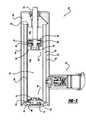
- FIG. 2is a cross-sectional side view of one of the shock absorbers illustrated in FIG. 1 ;
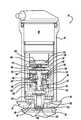
- FIG. 3is an enlarged cross-sectional side view of the externally mounted control valve illustrated in FIG. 2 ;
- FIG. 4is an enlarged cross-sectional side view of an externally mounted control valve in accordance with another embodiment of the disclosure.
- FIG. 1a vehicle incorporating a suspension system having shock absorbers in accordance with the present disclosure, and which is designated by the reference numeral 10 .
- Vehicle 10includes a rear suspension 12 , a front suspension 14 and a body 16 .
- Rear suspension 12has a transversely extending rear axle assembly (not shown) adapted to operatively support a pair of rear wheels 18 .
- the rear axleis attached to body 16 by means of a pair of shock absorbers 20 and by a pair of springs 22 .
- front suspension 14includes a transversely extending front axle assembly (not shown) to operatively support a pair of front wheels 24 .
- the front axle assemblyis attached to body 16 by means of a pair of shock absorbers 26 and by a pair of springs 28 .
- shock absorbers 20 and 26serve to dampen the relative motion of the unsprung portion (i.e., front and rear suspensions 12 , 14 ) with respect to the sprung portion (i.e., body 16 ) of vehicle 10 . While vehicle 10 has been depicted as a passenger car having front and rear axle assemblies, shock absorbers 20 and 26 may be used with other types of vehicles or in other types of applications including, but not limited to, vehicles incorporating non-independent front and/or non-independent rear suspensions, vehicles incorporating independent front and/or independent rear suspensions or other suspension systems known in the art. Further, the term “shock absorber” as used herein is meant to refer to dampers in general and thus will include McPherson struts and other damper designs known in the art.
- shock absorber 20is shown in greater detail. While FIG. 2 illustrates only shock absorber 20 , it is to be understood that shock absorber 26 also includes the control valve design described below for shock absorber 20 . Shock absorber 26 only differs from shock absorber 20 in the manner in which it is adapted to be connected to the sprung and unsprung masses of vehicle 10 . Shock absorber 20 comprises a pressure tube 30 , a piston assembly 32 , a piston rod 34 , a reserve tube 36 , a base valve assembly 38 , an intermediate tube 40 and an externally mounted control valve 42 .
- Pressure tube 30defines a working chamber 44 .
- Piston assembly 32is slidably disposed within pressure tube 30 and divides working chamber 44 into an upper working chamber 46 and a lower working chamber 48 .
- a sealis disposed between piston assembly 32 and pressure tube 30 to permit sliding movement of piston assembly 32 with respect to pressure tube 30 without generating undue frictional forces as well as sealing upper working chamber 46 from lower working chamber 48 .
- Piston rod 34is attached to piston assembly 32 and extends through upper working chamber 46 and through an upper rod guide assembly 50 which closes the upper end of pressure tube 30 .
- a sealing systemseals the interface between upper rod guide assembly 50 , reserve tube 36 and piston rod 34 .
- the end of piston rod 34 opposite to piston assembly 32is adapted to be secured to the sprung mass of vehicle 10 .
- piston rod 34extends only through upper working chamber 46 and not lower working chamber 48 , extension and compression movements of piston assembly 32 with respect to pressure tube 30 causes a difference in the amount of fluid displaced in upper working chamber 46 and the amount of fluid displaced in lower working chamber 48 .
- the difference in the amount of fluid displacedis known as the “rod volume” and during extension movements it flows through base valve assembly 38 .
- valving within piston assembly 32allow fluid flow from lower working chamber 48 to upper working chamber 46 and the “rod volume” of fluid flow flows through control valve 42 as described below.
- Reserve tube 36surrounds pressure tube 30 to define a fluid reserve chamber 52 located between tubes 30 and 36 .
- the bottom end of reserve tube 36is closed by a base cup 54 which is adapted to be connected to the unsprung mass of vehicle 10 .
- the upper end of reserve tube 36is attached to upper rod guide assembly 50 .
- Base valve assembly 38is disposed between lower working chamber 48 and reserve chamber 52 to control the flow of fluid from reserve chamber 52 to lower working chamber 48 .
- Piston assembly 32comprises a piston body 60 , a compression valve assembly 62 and an extension valve assembly 64 .
- a nut 66is assembled to piston rod 34 to secure compression valve assembly 62 , piston body 60 and extension valve assembly 64 to piston rod 34 .
- Piston body 60defines a plurality of compression passages 68 and a plurality of extension passages 70 .
- Base valve assembly 38comprises a valve body 72 , an extension valve assembly 74 and a compression valve assembly 76 .
- Valve body 72defines a plurality of extension passages 78 and a plurality of compression passages 80 .
- compression valve assembly 62acts as a check valve between lower working chamber 48 and upper working chamber 46 .
- the damping characteristics for shock absorber 20 during a compression strokeare controlled by control valve 42 alone and possibly by control valve 42 working in parallel with base valve assembly 38 as described below.
- Control valve 42controls the flow of fluid from lower working chamber 48 to upper working chamber 46 to control valve 42 to reserve chamber 52 due to the “rod volume” concept during a compression stroke as discussed below.
- Compression valve assembly 76controls the flow of fluid from lower working chamber 48 to reserve chamber 52 during a compression stroke.
- Compression valve assembly 76can be designed as a safety hydraulic relief valve, a damping valve working in parallel with control valve 42 or compression valve assembly can be removed from base valve assembly 38 . During an extension stroke, compression passages 68 are closed by compression valve assembly 62 .
- Extension valve assembly 64is designed as either a safety hydraulic relief valve which will open when the fluid pressure within upper working chamber 46 exceeds a predetermined limit or as a typical pressure valve working in parallel with control valve 42 to change the shape of the damping curve as discussed below.
- the damping characteristics for shock absorber 20 during an extension strokeare controlled by control valve 42 alone or by control valve 42 in parallel with extension valve assembly 64 as discussed below.
- Control valve 42controls the flow of fluid from upper working chamber 46 to reserve chamber 52 . Replacement flow of fluid into lower working chamber 48 during an extension stroke flows through base valve assembly 38 .
- Extension valve assembly 74acts as a check valve between reserve chamber 52 and lower working chamber 48 .
- the damping characteristics for shock absorber 20 during an extension strokeare controlled by control valve 42 alone and possibly by extension valve assembly 64 in parallel with control valve 42 as described below.
- Intermediate tube 40engages upper rod guide assembly 50 on an upper end and it engages base valve assembly 38 on a lower end.
- An intermediate chamber 82is defined between intermediate tube 40 and pressure tube 30 .
- a passage 84is formed in upper rod guide assembly 50 for fluidly connecting upper working chamber 46 and intermediate chamber 80 .
- Control valve 42comprises an attachment fitting 90 , a soft valve assembly 92 , a valve assembly 94 , a solenoid valve assembly 96 and an outer housing 98 .
- Attachment fitting 90defines an inlet passage 100 aligned with a fluid passage 102 which extends through intermediate tube 40 for fluid communication between intermediate chamber 82 and control valve 42 .
- Attachment fitting 90is axially received within a collar 104 mounted on intermediate tube 40 .
- An O-ringseals the interface between attachment fitting 90 and collar 104 .
- Collar 104is preferably a distinct piece from intermediate tube 40 and it is mounted onto intermediate tube 40 by welding or by any other means known in the art.
- Valve assembly 94includes a valve seat 106 and solenoid valve assembly 96 includes a valve body assembly 108 .
- Valve seat 106defines an axial bore 110 which receives fluid from soft valve assembly 92
- valve body assembly 108defines an axial bore 112 and a plurality of radial passages 114 which communicate with a return flow passage 120 which is in communication with reserve chamber 52 through a fluid passage 122 formed through reserve tube 36 .
- An attachment plate 124is secured to outer housing 98 to position attachment fitting 90 and the rest of the components of control valve 42 within outer housing 98 .
- shock absorber 20will be described when control valve 42 alone controls the damping loads for shock absorber 20 .
- compression valve assembly 62closes the plurality of compression passages 68 and fluid pressure within upper working chamber 46 increases. Fluid is forced from upper working chamber 46 , through passage 84 , into intermediate chamber 82 , through fluid passage 102 , through inlet passage 100 of attachment fitting 90 , through soft valve assembly 92 as discussed below, to reach valve assembly 94 .
- valve assembly 94 and solenoid valve assembly 96are configured to provide a predetermined damping function which is controlled by the signal provided to solenoid valve assembly 96 .
- the predetermined damping functioncan be anywhere between a soft damping function to a firm damping function based upon the operating conditions of vehicle 10 .
- control valve 42remains closed and fluid flows through bleed passages that are made in piston assembly 32 and base valve assembly 38 . Shock absorber 20 thus operates similar to a typical double tube damper.
- valve body assembly 108At higher piston velocities, as fluid flow increases, fluid pressure against a plunger 126 of valve body assembly 108 will separate plunger 126 of valve body assembly 108 from a valve seat 128 of valve body assembly 108 and fluid will flow between plunger 126 of valve body assembly 108 and valve seat 128 of valve body assembly 108 , through radial passages 114 , through return flow passage 120 , through fluid passage 122 and into reserve chamber 52 .
- the fluid pressure required to separate plunger 126 of valve body assembly 108 from valve seat 128 of valve body assembly 108will be determined by solenoid valve assembly 96 .
- the rebound or extension movement of piston assembly 32creates a low pressure within lower working chamber 48 .
- Extension valve assembly 74will open to allow fluid flow from reserve chamber 52 to lower working chamber 48 .
- compression valve assembly 62will open to allow fluid flow from lower working chamber 48 to upper working chamber 46 . Due to the “rod volume” concept, fluid in upper working chamber 46 will flow from upper working chamber 46 , through passage 84 , into intermediate chamber 82 , through fluid passage 102 , through inlet passage 100 of attachment fitting 90 , through soft valve assembly 92 as discussed below, to reach valve assembly 94 .
- valve assembly 94 and solenoid valve assembly 96are configured to provide a predetermined damping function which is controlled by the signal provided to solenoid valve assembly 96 .
- the predetermined damping functioncan be anywhere between a soft damping function to a firm damping function based upon the operating conditions of vehicle 10 .
- control valve 42remains closed and fluid flows through the bleed passages that are made in piston assembly 32 and base valve assembly 38 .
- Shock absorber 20thus operates similar to a typical double tube damper at higher piston velocities, as fluid flow increases, fluid pressure against plunger 126 of valve body assembly 108 will separate plunger 126 of valve body assembly 108 from valve seat 128 of valve body assembly 108 and fluid will flow between plunger 126 of valve body assembly 108 and valve seat 128 of valve body assembly 108 , through radial passages 114 , through return flow passage 120 , through fluid passage 122 and into reserve chamber 52 .
- the fluid pressure required to separate plunger 126 of valve body assembly 108 from valve seat 128 of valve body assembly 108will be determined by solenoid valve assembly 96 .
- the damping characteristics for both an extension stroke and a compression strokeare controlled by control valve 42 in the same manner.
- Soft valve assembly 92comprises a valve body 130 , a valve pin 132 , an intake disc 134 , an orifice disc 136 , a spacer 138 , an upper spring seat 140 , a biasing spring 142 and a lower spring seat 144 .
- Valve body 130is disposed between attachment fitting 90 and valve seat 106 .
- An O-ringseals the interface between valve body 130 and attachment fitting 90 and an O-ring seals the interface between valve body 130 and valve seat 106 .
- Valve body 130defines a plurality of fluid passages 146 and a central bore 148 .
- Valve pin 132extends through central bore 148 .
- Intake disc 134 and orifice disc 136are disposed between valve body 130 and valve pin 132 with orifice disc 136 engaging an annular land 150 on valve body 130 to close fluid passages 146 and intake disc 134 being disposed between orifice disc 136 and valve pin 132 .
- One or more bleed orifices 152are defined by orifice disc 136 to allow a bleed flow of fluid through soft valve assembly 92 as discussed below. While the present disclosure illustrates orifice disc 136 having bleed orifices 152 , it is within the scope of the present disclosure to have annular land 150 define bleed orifices 152 .
- valve pin 132Assembled to valve pin 132 on the side of valve body 130 opposite to intake disc 134 and orifice disc 136 are spacer 138 , upper spring seat 140 , biasing spring 142 and lower spring seat 144 . Lower spring seat 144 is secured to valve pin 132 to maintain the assembly of soft valve assembly 92 . Biasing spring 142 urges valve pin 132 against intake disc 134 which is biased against orifice disc 136 which is biased against annular land 150 on valve body 130 .
- Soft valve assembly 92provides for the tuning of damping forces at low current levels for solenoid valve assembly 96 .
- Fluid flow flowing to soft valve assembly 92 from inlet passage 100 of attachment fitting 90is directed to fluid passages 146 .
- the initial fluid flowwill flow through bleed orifices 152 to valve assembly 94 through valve seat 106 .
- Fluid flow through valve assembly 94is described above.
- the fluid pressure against orifice disc 136 and intake disc 134will eventually overcome the biasing load produced by biasing spring 142 and orifice disc 136 will unseat from annular land 150 to open soft valve assembly 92 .
- This fluid flowwill also be directed to valve assembly 94 through valve seat 106 .
- Tuning for soft valve assembly 92can be accomplished by varying the size and/or load of biasing spring 142 , varying the thickness and/or flexibility of intake disc 134 and/or orifice disc 136 , varying the size and/or number of bleed orifices 152 and varying the size and/or number of fluid passages 146 .
- the incorporation of soft valve assembly 92allows for the tuning or alteration of the shape of the damping curve at low current levels to solenoid valve assembly 96 to adapt shock absorber 20 to a specific vehicle performance. Because the pressure drop across soft valve assembly 92 is very low at high current levels to solenoid valve assembly 96 compared to the pressure drop across control valve 42 , its effect on the damping characteristics is negligible.
- soft valve assembly 92allows for the tuning or alteration of the shape of the damping curve only at low current levels to solenoid valve assembly 96 .
- extension valve assembly 64needs to be changed and compression valve assembly 76 needs to be included.
- extension valve assembly 64 and compression valve assembly 76are designed as hydraulic pressure relief valves or they are removed from the assembly. In order to tune or alter the damping curve at high current levels to solenoid valve assembly, extension valve assembly 64 and compression valve assembly 76 are designed as damping valves for opening at specific fluid pressures to contribute to the damping characteristics for shock absorber 20 in parallel with control valve 42 .
- Soft valve assembly 192is a direct replacement for soft valve assembly 92 with soft valve assembly 192 being disposed between an attachment fitting 190 and a valve seat 206 .
- Attachment fitting 190is a direct replacement for attachment fitting 90 and valve seat 206 is a direct replacement for valve seat 106 .
- Soft valve assembly 192comprises a valve body 230 , a valve pin 232 , a plurality of intake discs 234 , an orifice disc 236 and a valve retainer 238 .
- Valve body 230is disposed between attachment fitting 190 and valve seat 206 .
- Valve body 230defines a plurality of fluid passages 246 and a central bore 248 .
- Valve pin 232extend through central bore 248 .
- Valve retainer 238 , the plurality of intake discs 234 and orifice disc 236are disposed between valve body 230 and valve pin 232 with orifice disc 236 engaging an annular land 250 on valve body 230 to close fluid passages 246 .
- the plurality of intake discs 234 engage orifice disc 236 and valve retainer 238is disposed between the plurality of intake discs 234 and valve pin 232 .
- One or more bleed orifices 252are defined by orifice disc 236 to allow a bleed flow of fluid through soft valve assembly 192 as discussed below. While the present disclosure illustrates orifice disc 236 having bleed orifices 252 , it is within the scope of the present disclosure to have annular land 250 define bleed orifices 252 .
- Soft valve assembly 192provides for the tuning of damping forces at low current levels for solenoid valve assembly 96 .
- Fluid flow flowing to soft valve assembly 192 from inlet passage 100 of attachment fitting 190is directed to fluid passages 246 .
- the initial fluid flowwill flow through bleed orifices 252 to valve assembly 94 through valve seat 206 .
- Fluid flow through valve assembly 94is described above.
- the fluid pressure against orifice disc 236 and the plurality of intake discs 234will eventually overcome the bending load for the plurality of intake discs 234 and orifice disc 236 and orifice disc 236 will unseat from annular land 250 to open soft valve assembly 192 .
- Tuning for soft valve assembly 192can be accomplished by varying the thickness and/or flexibility of the plurality of intake discs 234 and/or orifice disc 236 , varying the size and/or number of bleed orifices 252 and varying the size and/or number of fluid passages 246 .
- the incorporation of soft valve assembly 192allows for the tuning or alteration of the shape of the damping curve to adapt shock absorber 20 to a specific vehicle performance.
Landscapes
- Engineering & Computer Science (AREA)
- General Engineering & Computer Science (AREA)
- Mechanical Engineering (AREA)
- Physics & Mathematics (AREA)
- Electromagnetism (AREA)
- Fluid-Damping Devices (AREA)
- Vehicle Body Suspensions (AREA)
Abstract
Description
Claims (9)
Priority Applications (2)
| Application Number | Priority Date | Filing Date | Title |
|---|---|---|---|
| US13/034,050US8256586B2 (en) | 2007-04-16 | 2011-02-24 | Shock absorber having a continuously variable valve with base line valving |
| US13/477,142US8511444B2 (en) | 2007-04-16 | 2012-05-22 | Shock absorber having a continuously variable valve with base line valving |
Applications Claiming Priority (2)
| Application Number | Priority Date | Filing Date | Title |
|---|---|---|---|
| US11/787,452US7926632B2 (en) | 2007-04-16 | 2007-04-16 | Shock absorber having a continuously variable valve with base line valving |
| US13/034,050US8256586B2 (en) | 2007-04-16 | 2011-02-24 | Shock absorber having a continuously variable valve with base line valving |
Related Parent Applications (1)
| Application Number | Title | Priority Date | Filing Date |
|---|---|---|---|
| US11/787,452ContinuationUS7926632B2 (en) | 2007-04-16 | 2007-04-16 | Shock absorber having a continuously variable valve with base line valving |
Related Child Applications (1)
| Application Number | Title | Priority Date | Filing Date |
|---|---|---|---|
| US13/477,142ContinuationUS8511444B2 (en) | 2007-04-16 | 2012-05-22 | Shock absorber having a continuously variable valve with base line valving |
Publications (2)
| Publication Number | Publication Date |
|---|---|
| US20110139557A1 US20110139557A1 (en) | 2011-06-16 |
| US8256586B2true US8256586B2 (en) | 2012-09-04 |
Family
ID=39852700
Family Applications (3)
| Application Number | Title | Priority Date | Filing Date |
|---|---|---|---|
| US11/787,452Active2028-09-29US7926632B2 (en) | 2007-04-16 | 2007-04-16 | Shock absorber having a continuously variable valve with base line valving |
| US13/034,050ActiveUS8256586B2 (en) | 2007-04-16 | 2011-02-24 | Shock absorber having a continuously variable valve with base line valving |
| US13/477,142ActiveUS8511444B2 (en) | 2007-04-16 | 2012-05-22 | Shock absorber having a continuously variable valve with base line valving |
Family Applications Before (1)
| Application Number | Title | Priority Date | Filing Date |
|---|---|---|---|
| US11/787,452Active2028-09-29US7926632B2 (en) | 2007-04-16 | 2007-04-16 | Shock absorber having a continuously variable valve with base line valving |
Family Applications After (1)
| Application Number | Title | Priority Date | Filing Date |
|---|---|---|---|
| US13/477,142ActiveUS8511444B2 (en) | 2007-04-16 | 2012-05-22 | Shock absorber having a continuously variable valve with base line valving |
Country Status (7)
| Country | Link |
|---|---|
| US (3) | US7926632B2 (en) |
| JP (4) | JP2010525256A (en) |
| KR (1) | KR101454050B1 (en) |
| CN (2) | CN103148155B (en) |
| BR (1) | BRPI0810528A2 (en) |
| DE (1) | DE112008000666T8 (en) |
| WO (1) | WO2008130547A1 (en) |
Cited By (1)
| Publication number | Priority date | Publication date | Assignee | Title |
|---|---|---|---|---|
| US20100326267A1 (en)* | 2009-06-30 | 2010-12-30 | Hata Hideki | Hydraulic cylinder |
Families Citing this family (43)
| Publication number | Priority date | Publication date | Assignee | Title |
|---|---|---|---|---|
| US7926632B2 (en)* | 2007-04-16 | 2011-04-19 | Tenneco Automotive Operating Company Inc. | Shock absorber having a continuously variable valve with base line valving |
| US20110042173A1 (en)* | 2009-08-18 | 2011-02-24 | Magneti Marelli Cofap Companhia Fabricadora De Pecas | Hydraulic Damper for a Vehicle Steering System |
| JP5387841B2 (en)* | 2009-09-30 | 2014-01-15 | 日立オートモティブシステムズ株式会社 | Damping force adjustable shock absorber |
| US8616351B2 (en) | 2009-10-06 | 2013-12-31 | Tenneco Automotive Operating Company Inc. | Damper with digital valve |
| JP5415992B2 (en)* | 2010-02-25 | 2014-02-12 | 株式会社ショーワ | Hydraulic shock absorber |
| WO2012006294A1 (en)* | 2010-07-05 | 2012-01-12 | Fluid Ride Ltd. | Suspension strut for a vehicle |
| KR101230550B1 (en)* | 2010-11-08 | 2013-02-07 | 주식회사 만도 | Damping force controlling valve assembly for shock absorber |
| PL2732182T3 (en) | 2011-07-12 | 2017-09-29 | Beijingwest Industries Co. Ltd. | A hydraulic mount apparatus for supporting vibration source |
| CN103827540B (en)* | 2011-07-12 | 2015-03-11 | 北京京西重工有限公司 | Magneto-rheological fluid-based support device with rate-dropping magnetic track channels |
| US8607943B2 (en)* | 2011-09-08 | 2013-12-17 | Hitachi Automotive Systems Americas Inc. | Shock absorber |
| US20130081913A1 (en)* | 2011-10-04 | 2013-04-04 | Tenneco Automotive Operating Company Inc. | Welding of transfer ring on round tube |
| DE102012022030A1 (en)* | 2012-11-12 | 2014-05-15 | Deere & Company | Suspension device for a movably mounted vehicle axle |
| EP2759735B1 (en)* | 2013-01-29 | 2016-06-15 | Integrated Dynamics Engineering GmbH | Stationary vibration insulation system and method for regulating a vibration insulation system |
| US9217483B2 (en) | 2013-02-28 | 2015-12-22 | Tenneco Automotive Operating Company Inc. | Valve switching controls for adjustable damper |
| US9884533B2 (en) | 2013-02-28 | 2018-02-06 | Tenneco Automotive Operating Company Inc. | Autonomous control damper |
| JP6346908B2 (en) | 2013-02-28 | 2018-06-20 | テネコ オートモティブ オペレーティング カンパニー インコーポレイテッドTenneco Automotive Operating Company Inc. | Damper with integrated electronic circuit |
| JP5952760B2 (en)* | 2013-03-13 | 2016-07-13 | Kyb株式会社 | Damping valve |
| US9879746B2 (en) | 2013-03-15 | 2018-01-30 | Tenneco Automotive Operating Company Inc. | Rod guide system and method with multiple solenoid valve cartridges and multiple pressure regulated valve assemblies |
| BR112015023459A2 (en) | 2013-03-15 | 2017-07-18 | Tenneco Automotive Operating Co Inc | stem guide assembly with multi-piece valve assembly |
| US9879748B2 (en) | 2013-03-15 | 2018-01-30 | Tenneco Automotive Operating Company Inc. | Two position valve with face seal and pressure relief port |
| US9163691B2 (en) | 2013-03-15 | 2015-10-20 | Tenneco Automotive Operating Company Inc. | Rod guide arrangement for electronically controlled valve applications |
| JP6114667B2 (en)* | 2013-09-17 | 2017-04-12 | Kyb株式会社 | Damping valve |
| DE102013218658B4 (en)* | 2013-09-18 | 2022-08-25 | Zf Friedrichshafen Ag | Adjustable damping valve device |
| DE102014210701A1 (en)* | 2014-06-05 | 2015-12-17 | Zf Friedrichshafen Ag | Vibration damper and motor vehicle |
| US9441700B2 (en)* | 2014-08-14 | 2016-09-13 | Tenneco Automotive Operating Company Inc. | Shock absorber with frequency dependent passive valve |
| KR101671920B1 (en)* | 2015-01-09 | 2016-11-03 | 주식회사 만도 | Damping force controlling type shock absorber |
| DE102015203522A1 (en)* | 2015-02-27 | 2016-09-01 | Zf Friedrichshafen Ag | Piston rod cylinder unit with an intermediate pipe |
| KR102386300B1 (en) | 2015-05-15 | 2022-04-14 | 주식회사 만도 | Body valve assembly of internal variable damper for vehicle |
| US10876589B2 (en)* | 2015-08-31 | 2020-12-29 | Hitachi Automotive Systems, Ltd. | Shock absorber |
| BE1023718B1 (en) | 2016-01-01 | 2017-06-26 | Shi Yan | Shock absorber with frequency dependent piston assembly |
| US10588233B2 (en) | 2017-06-06 | 2020-03-10 | Tenneco Automotive Operating Company Inc. | Damper with printed circuit board carrier |
| US10479160B2 (en) | 2017-06-06 | 2019-11-19 | Tenneco Automotive Operating Company Inc. | Damper with printed circuit board carrier |
| DE112017007694T5 (en)* | 2017-06-27 | 2020-03-12 | Showa Corporation | HYDRAULIC DAMPING DEVICE |
| JP6302148B1 (en)* | 2017-06-27 | 2018-03-28 | 株式会社ショーワ | Pressure shock absorber |
| DE102017220344B4 (en) | 2017-11-15 | 2025-01-23 | Volkswagen Aktiengesellschaft | damper for a vehicle |
| EP3569890B1 (en)* | 2018-05-14 | 2024-06-26 | DRiV Automotive Inc. | A shock absorber and method for controlling a damping flow in a shock absorber and the use of two electrical continuously controlled valve arrangements for controlling a damping flow in a shock absorber |
| IT201800007584A1 (en)* | 2018-07-27 | 2020-01-27 | Sistemi Sospensioni Spa | Variable damping hydraulic shock absorber, particularly for vehicle suspension. |
| US11091001B2 (en)* | 2019-09-23 | 2021-08-17 | DRiV Automotive Inc. | Base valve assembly for damper |
| CN110686035B (en)* | 2019-09-29 | 2024-11-08 | 成都博仕腾科技有限公司 | A dual oil circuit mechanically controlled variable damping passive oil pressure shock absorber for railway vehicles |
| CN110701232B (en)* | 2019-09-29 | 2024-11-08 | 成都博仕腾科技有限公司 | A semi-active hydraulic shock absorber with dual oil circuits and electronically controlled variable damping for railway vehicles |
| US11719305B2 (en)* | 2019-11-08 | 2023-08-08 | DRiV Automotive Inc. | Balanced continuously semi-active damper |
| DE102020210540A1 (en)* | 2020-08-19 | 2022-02-24 | Thyssenkrupp Ag | Vibration damper and a center tube for a vibration damper |
| CN114791027B (en)* | 2021-10-11 | 2023-05-12 | 广西科技大学 | Built-in hydraulic valve type damper with adjustable damping gap |
Citations (13)
| Publication number | Priority date | Publication date | Assignee | Title |
|---|---|---|---|---|
| US4850460A (en) | 1987-04-13 | 1989-07-25 | Boge Ag | Hydraulic adjustable shock absorber |
| JPH1047413A (en) | 1996-07-31 | 1998-02-20 | Tokico Ltd | Damping force adjustable hydraulic shock absorber |
| US5730261A (en) | 1996-01-11 | 1998-03-24 | General Motors Corporation | Damper control valve |
| US5813500A (en)* | 1996-03-25 | 1998-09-29 | Tenneco Automotive Inc. | Anti-swish mechanism for a damper |
| KR100211201B1 (en) | 1996-06-20 | 1999-07-15 | 다가야 레이지 | Damping force adjustable type hydraulic shock absorber |
| US5960915A (en) | 1996-08-09 | 1999-10-05 | Tokico, Ltd. | Hydraulic shock absorber of damping force adjusting type |
| US6079526A (en) | 1995-12-26 | 2000-06-27 | Tokico Ltd. | Damping force control type hydraulic shock absorber |
| US6155391A (en) | 1998-03-31 | 2000-12-05 | Tokico Ltd. | Hydraulic shock absorber of a dumping force adjustable type |
| JP2001012534A (en) | 1999-06-30 | 2001-01-16 | Tokico Ltd | Damping force adjustable hydraulic shock absorber |
| US6182805B1 (en) | 1998-06-26 | 2001-02-06 | Tokico Ltd. | Damping force control type hydraulic shock absorber |
| US6321888B1 (en) | 1999-05-25 | 2001-11-27 | Tenneco Automotive Inc. | Damper with externally mounted semi-active system |
| US6527093B2 (en) | 2001-02-09 | 2003-03-04 | Delphi Technologies, Inc. | Pressure controlled suspension damper |
| US7926632B2 (en)* | 2007-04-16 | 2011-04-19 | Tenneco Automotive Operating Company Inc. | Shock absorber having a continuously variable valve with base line valving |
Family Cites Families (15)
| Publication number | Priority date | Publication date | Assignee | Title |
|---|---|---|---|---|
| JPS5594043A (en)* | 1979-01-09 | 1980-07-17 | Kayaba Ind Co Ltd | Valve mechanism for hydraulic damper |
| US4346794A (en)* | 1980-02-04 | 1982-08-31 | Maremont Corporation | Shock absorber with improved back check and anti-dump valve mechanisms |
| JPS63178645U (en)* | 1987-05-12 | 1988-11-18 | ||
| GB8928943D0 (en)* | 1989-12-21 | 1990-02-28 | Monroe Europ U K Ltd | Adaptive shock absorbers and damping valves therefor |
| JPH04345516A (en)* | 1991-05-24 | 1992-12-01 | Kayaba Ind Co Ltd | shock absorber device |
| US5163538A (en)* | 1991-09-03 | 1992-11-17 | General Motors Company | Low level damping valve and method for a semi-active hydraulic damper |
| JP3455887B2 (en)* | 1994-09-30 | 2003-10-14 | トキコ株式会社 | Air suspension device |
| JP3479732B2 (en)* | 1994-11-18 | 2003-12-15 | トキコ株式会社 | Damping force adjustable hydraulic shock absorber |
| JP3829264B2 (en)* | 1996-03-19 | 2006-10-04 | 株式会社日立製作所 | Damping force adjustable hydraulic shock absorber |
| JPH1096440A (en)* | 1996-09-20 | 1998-04-14 | Kayaba Ind Co Ltd | Load-sensitive shock absorber |
| KR100507756B1 (en) | 1999-02-10 | 2005-08-10 | 주식회사 만도 | Apparatus for adjusting a damping force of a shock absorber using magnetoreological fluid |
| NL1019313C2 (en)* | 2001-11-06 | 2003-05-12 | Koni Bv | Shock absorber with frequency dependent damping. |
| JP2007046668A (en)* | 2005-08-09 | 2007-02-22 | Kayaba Ind Co Ltd | Valve structure |
| JP4630757B2 (en)* | 2005-08-09 | 2011-02-09 | カヤバ工業株式会社 | Valve structure |
| JP4695490B2 (en)* | 2005-10-28 | 2011-06-08 | カヤバ工業株式会社 | Shock absorber valve structure and shock absorber |
- 2007
- 2007-04-16USUS11/787,452patent/US7926632B2/enactiveActive
- 2008
- 2008-04-15BRBRPI0810528-6A2Apatent/BRPI0810528A2/ennot_activeIP Right Cessation
- 2008-04-15KRKR1020097021375Apatent/KR101454050B1/ennot_activeExpired - Fee Related
- 2008-04-15CNCN201210513049.8Apatent/CN103148155B/enactiveActive
- 2008-04-15DEDE112008000666Tpatent/DE112008000666T8/enactiveActive
- 2008-04-15JPJP2010504066Apatent/JP2010525256A/enactivePending
- 2008-04-15WOPCT/US2008/004855patent/WO2008130547A1/enactiveApplication Filing
- 2008-04-15CNCN2008800118561Apatent/CN101657651B/enactiveActive
- 2011
- 2011-02-24USUS13/034,050patent/US8256586B2/enactiveActive
- 2012
- 2012-05-22USUS13/477,142patent/US8511444B2/enactiveActive
- 2013
- 2013-07-04JPJP2013140552Apatent/JP2013224743A/enactivePending
- 2014
- 2014-12-02JPJP2014243996Apatent/JP2015064106A/enactivePending
- 2014-12-02JPJP2014244002Apatent/JP6174000B2/enactiveActive
Patent Citations (13)
| Publication number | Priority date | Publication date | Assignee | Title |
|---|---|---|---|---|
| US4850460A (en) | 1987-04-13 | 1989-07-25 | Boge Ag | Hydraulic adjustable shock absorber |
| US6079526A (en) | 1995-12-26 | 2000-06-27 | Tokico Ltd. | Damping force control type hydraulic shock absorber |
| US5730261A (en) | 1996-01-11 | 1998-03-24 | General Motors Corporation | Damper control valve |
| US5813500A (en)* | 1996-03-25 | 1998-09-29 | Tenneco Automotive Inc. | Anti-swish mechanism for a damper |
| KR100211201B1 (en) | 1996-06-20 | 1999-07-15 | 다가야 레이지 | Damping force adjustable type hydraulic shock absorber |
| JPH1047413A (en) | 1996-07-31 | 1998-02-20 | Tokico Ltd | Damping force adjustable hydraulic shock absorber |
| US5960915A (en) | 1996-08-09 | 1999-10-05 | Tokico, Ltd. | Hydraulic shock absorber of damping force adjusting type |
| US6155391A (en) | 1998-03-31 | 2000-12-05 | Tokico Ltd. | Hydraulic shock absorber of a dumping force adjustable type |
| US6182805B1 (en) | 1998-06-26 | 2001-02-06 | Tokico Ltd. | Damping force control type hydraulic shock absorber |
| US6321888B1 (en) | 1999-05-25 | 2001-11-27 | Tenneco Automotive Inc. | Damper with externally mounted semi-active system |
| JP2001012534A (en) | 1999-06-30 | 2001-01-16 | Tokico Ltd | Damping force adjustable hydraulic shock absorber |
| US6527093B2 (en) | 2001-02-09 | 2003-03-04 | Delphi Technologies, Inc. | Pressure controlled suspension damper |
| US7926632B2 (en)* | 2007-04-16 | 2011-04-19 | Tenneco Automotive Operating Company Inc. | Shock absorber having a continuously variable valve with base line valving |
Non-Patent Citations (1)
| Title |
|---|
| International Search Report and Written Opinion regarding PCT/US2008/004855 dated Aug. 27, 2008. |
Cited By (2)
| Publication number | Priority date | Publication date | Assignee | Title |
|---|---|---|---|---|
| US20100326267A1 (en)* | 2009-06-30 | 2010-12-30 | Hata Hideki | Hydraulic cylinder |
| US8495947B2 (en)* | 2009-06-30 | 2013-07-30 | Hitachi Automotive Systems, Ltd. | Hydraulic cylinder |
Also Published As
| Publication number | Publication date |
|---|---|
| CN103148155B (en) | 2015-07-01 |
| BRPI0810528A2 (en) | 2014-10-21 |
| JP2015064107A (en) | 2015-04-09 |
| US20110139557A1 (en) | 2011-06-16 |
| JP2010525256A (en) | 2010-07-22 |
| DE112008000666T8 (en) | 2010-06-10 |
| US20080251331A1 (en) | 2008-10-16 |
| CN101657651A (en) | 2010-02-24 |
| JP2015064106A (en) | 2015-04-09 |
| DE112008000666T5 (en) | 2010-03-04 |
| US7926632B2 (en) | 2011-04-19 |
| US8511444B2 (en) | 2013-08-20 |
| KR20090128483A (en) | 2009-12-15 |
| CN101657651B (en) | 2013-01-09 |
| US20120228072A1 (en) | 2012-09-13 |
| JP2013224743A (en) | 2013-10-31 |
| JP6174000B2 (en) | 2017-08-02 |
| WO2008130547A1 (en) | 2008-10-30 |
| CN103148155A (en) | 2013-06-12 |
| KR101454050B1 (en) | 2014-11-03 |
Similar Documents
| Publication | Publication Date | Title |
|---|---|---|
| US8256586B2 (en) | Shock absorber having a continuously variable valve with base line valving | |
| US7950506B2 (en) | Semi third tube design | |
| US8511447B2 (en) | Triple tube shock absorber having a shortened intermediate tube | |
| US7743896B2 (en) | Shock absorber having a continuously variable semi-active valve | |
| US8511446B2 (en) | Nested check high speed valve | |
| EP2158416B1 (en) | Junction bleed | |
| US9033121B2 (en) | High velocity compression damping valve | |
| US9074651B2 (en) | Dual range damping system for a shock absorber | |
| US20090057079A1 (en) | Disc spring intake | |
| WO2007021753A2 (en) | Asymmetrical intake damper valve | |
| WO2005036016A1 (en) | Extra support land for valve disc | |
| US9285011B2 (en) | High velocity compression damping valve | |
| WO2005033546A1 (en) | Extra support area for valve disc | |
| EP1664581B1 (en) | Shock absorber | |
| US6148969A (en) | Frequency dependant damper |
Legal Events
| Date | Code | Title | Description |
|---|---|---|---|
| FEPP | Fee payment procedure | Free format text:PAYOR NUMBER ASSIGNED (ORIGINAL EVENT CODE: ASPN); ENTITY STATUS OF PATENT OWNER: LARGE ENTITY | |
| STCF | Information on status: patent grant | Free format text:PATENTED CASE | |
| AS | Assignment | Owner name:JPMORGAN CHASE BANK, N.A., AS ADMINISTRATIVE AGENT Free format text:SECURITY INTEREST;ASSIGNOR:TENNECO AUTOMOTIVE OPERATING COMPANY INC.;REEL/FRAME:034674/0291 Effective date:20141208 | |
| FPAY | Fee payment | Year of fee payment:4 | |
| AS | Assignment | Owner name:JPMORGAN CHASE BANK, N.A., AS ADMINISTRATIVE AGENT, ILLINOIS Free format text:GRANT OF SECURITY INTEREST IN PATENT RIGHTS;ASSIGNOR:TENNECO AUTOMOTIVE OPERATING COMPANY INC.;REEL/FRAME:042809/0515 Effective date:20170512 Owner name:JPMORGAN CHASE BANK, N.A., AS ADMINISTRATIVE AGENT Free format text:GRANT OF SECURITY INTEREST IN PATENT RIGHTS;ASSIGNOR:TENNECO AUTOMOTIVE OPERATING COMPANY INC.;REEL/FRAME:042809/0515 Effective date:20170512 | |
| AS | Assignment | Owner name:WILMINGTON TRUST, NATIONAL ASSOCIATION, AS COLLATERAL TRUSTEE, MINNESOTA Free format text:CONFIRMATORY GRANT OF SECURITY INTERESTS IN UNITED STATES PATENTS;ASSIGNORS:TENNECO INC.;TENNECO AUTOMOTIVE OPERATING COMPANY INC.;TENNECO INTERNATIONAL HOLDING CORP.;AND OTHERS;REEL/FRAME:047223/0001 Effective date:20181001 Owner name:WILMINGTON TRUST, NATIONAL ASSOCIATION, AS COLLATE Free format text:CONFIRMATORY GRANT OF SECURITY INTERESTS IN UNITED STATES PATENTS;ASSIGNORS:TENNECO INC.;TENNECO AUTOMOTIVE OPERATING COMPANY INC.;TENNECO INTERNATIONAL HOLDING CORP.;AND OTHERS;REEL/FRAME:047223/0001 Effective date:20181001 | |
| AS | Assignment | Owner name:TENNECO AUTOMOTIVE OPERATING COMPANY INC., ILLINOIS Free format text:RELEASE BY SECURED PARTY;ASSIGNOR:JPMORGAN CHASE BANK, N.A.;REEL/FRAME:048099/0716 Effective date:20181001 Owner name:TENNECO AUTOMOTIVE OPERATING COMPANY INC., ILLINOI Free format text:RELEASE BY SECURED PARTY;ASSIGNOR:JPMORGAN CHASE BANK, N.A.;REEL/FRAME:048099/0716 Effective date:20181001 | |
| MAFP | Maintenance fee payment | Free format text:PAYMENT OF MAINTENANCE FEE, 8TH YEAR, LARGE ENTITY (ORIGINAL EVENT CODE: M1552); ENTITY STATUS OF PATENT OWNER: LARGE ENTITY Year of fee payment:8 | |
| AS | Assignment | Owner name:WILMINGTON TRUST, NATIONAL ASSOCIATION, MINNESOTA Free format text:SECURITY AGREEMENT;ASSIGNORS:TENNECO INC.;THE PULLMAN COMPANY;FEDERAL-MOGUL IGNITION LLC;AND OTHERS;REEL/FRAME:054555/0592 Effective date:20201130 | |
| AS | Assignment | Owner name:TENNECO AUTOMOTIVE OPERATING COMPANY INC., ILLINOIS Free format text:CONFIRMATION OF TERMINATION AND RELEASE OF SECURITY INTEREST IN PATENT RIGHTS (R/F 34674/0291);ASSIGNOR:JPMORGAN CHASE BANK, N.A., AS ADMINISTRATIVE AGENT;REEL/FRAME:055429/0503 Effective date:20210226 | |
| AS | Assignment | Owner name:WILMINGTON TRUST, NATIONAL ASSOCIATION, MINNESOTA Free format text:SECURITY AGREEMENT;ASSIGNORS:TENNECO INC.;TENNECO AUTOMOTIVE OPERATING COMPANY INC.;THE PULLMAN COMPANY;AND OTHERS;REEL/FRAME:055626/0065 Effective date:20210317 | |
| AS | Assignment | Owner name:DRIV AUTOMOTIVE INC., MICHIGAN Free format text:RELEASE BY SECURED PARTY;ASSIGNOR:WILMINGTON TRUST, NATIONAL ASSOCIATION;REEL/FRAME:061971/0156 Effective date:20221117 Owner name:FEDERAL-MOGUL CHASSIS LLC, MICHIGAN Free format text:RELEASE BY SECURED PARTY;ASSIGNOR:WILMINGTON TRUST, NATIONAL ASSOCIATION;REEL/FRAME:061971/0156 Effective date:20221117 Owner name:FEDERAL-MOGUL WORLD WIDE LLC, MICHIGAN Free format text:RELEASE BY SECURED PARTY;ASSIGNOR:WILMINGTON TRUST, NATIONAL ASSOCIATION;REEL/FRAME:061971/0156 Effective date:20221117 Owner name:FEDERAL-MOGUL MOTORPARTS LLC, MICHIGAN Free format text:RELEASE BY SECURED PARTY;ASSIGNOR:WILMINGTON TRUST, NATIONAL ASSOCIATION;REEL/FRAME:061971/0156 Effective date:20221117 Owner name:FEDERAL-MOGUL PRODUCTS US LLC, MICHIGAN Free format text:RELEASE BY SECURED PARTY;ASSIGNOR:WILMINGTON TRUST, NATIONAL ASSOCIATION;REEL/FRAME:061971/0156 Effective date:20221117 Owner name:FEDERAL-MOGUL POWERTRAIN LLC, MICHIGAN Free format text:RELEASE BY SECURED PARTY;ASSIGNOR:WILMINGTON TRUST, NATIONAL ASSOCIATION;REEL/FRAME:061971/0156 Effective date:20221117 Owner name:FEDERAL-MOGUL IGNITION LLC, MICHIGAN Free format text:RELEASE BY SECURED PARTY;ASSIGNOR:WILMINGTON TRUST, NATIONAL ASSOCIATION;REEL/FRAME:061971/0156 Effective date:20221117 Owner name:THE PULLMAN COMPANY, OHIO Free format text:RELEASE BY SECURED PARTY;ASSIGNOR:WILMINGTON TRUST, NATIONAL ASSOCIATION;REEL/FRAME:061971/0156 Effective date:20221117 Owner name:TENNECO AUTOMOTIVE OPERATING COMPANY INC., ILLINOIS Free format text:RELEASE BY SECURED PARTY;ASSIGNOR:WILMINGTON TRUST, NATIONAL ASSOCIATION;REEL/FRAME:061971/0156 Effective date:20221117 Owner name:TENNECO INC., ILLINOIS Free format text:RELEASE BY SECURED PARTY;ASSIGNOR:WILMINGTON TRUST, NATIONAL ASSOCIATION;REEL/FRAME:061971/0156 Effective date:20221117 Owner name:FEDERAL-MOGUL PRODUCTS US LLC, MICHIGAN Free format text:RELEASE BY SECURED PARTY;ASSIGNOR:WILMINGTON TRUST, NATIONAL ASSOCIATION;REEL/FRAME:061975/0218 Effective date:20221117 Owner name:FEDERAL-MOGUL FINANCING CORPORATION, MICHIGAN Free format text:RELEASE BY SECURED PARTY;ASSIGNOR:WILMINGTON TRUST, NATIONAL ASSOCIATION;REEL/FRAME:061975/0218 Effective date:20221117 Owner name:FEDERAL-MOGUL FILTRATION LLC, MICHIGAN Free format text:RELEASE BY SECURED PARTY;ASSIGNOR:WILMINGTON TRUST, NATIONAL ASSOCIATION;REEL/FRAME:061975/0218 Effective date:20221117 Owner name:BECK ARNLEY HOLDINGS LLC, MICHIGAN Free format text:RELEASE BY SECURED PARTY;ASSIGNOR:WILMINGTON TRUST, NATIONAL ASSOCIATION;REEL/FRAME:061975/0218 Effective date:20221117 Owner name:FEDERAL-MOGUL SEVIERVILLE, LLC, MICHIGAN Free format text:RELEASE BY SECURED PARTY;ASSIGNOR:WILMINGTON TRUST, NATIONAL ASSOCIATION;REEL/FRAME:061975/0218 Effective date:20221117 Owner name:FEDERAL-MOGUL VALVE TRAIN INTERNATIONAL LLC, MICHIGAN Free format text:RELEASE BY SECURED PARTY;ASSIGNOR:WILMINGTON TRUST, NATIONAL ASSOCIATION;REEL/FRAME:061975/0218 Effective date:20221117 Owner name:F-M TSC REAL ESTATE HOLDINGS LLC, MICHIGAN Free format text:RELEASE BY SECURED PARTY;ASSIGNOR:WILMINGTON TRUST, NATIONAL ASSOCIATION;REEL/FRAME:061975/0218 Effective date:20221117 Owner name:F-M MOTORPARTS TSC LLC, MICHIGAN Free format text:RELEASE BY SECURED PARTY;ASSIGNOR:WILMINGTON TRUST, NATIONAL ASSOCIATION;REEL/FRAME:061975/0218 Effective date:20221117 Owner name:FEDERAL-MOGUL CHASSIS LLC, MICHIGAN Free format text:RELEASE BY SECURED PARTY;ASSIGNOR:WILMINGTON TRUST, NATIONAL ASSOCIATION;REEL/FRAME:061975/0218 Effective date:20221117 Owner name:FEDERAL-MOGUL MOTORPARTS LLC, MICHIGAN Free format text:RELEASE BY SECURED PARTY;ASSIGNOR:WILMINGTON TRUST, NATIONAL ASSOCIATION;REEL/FRAME:061975/0218 Effective date:20221117 Owner name:FEDERAL-MOGUL IGNITION LLC, MICHIGAN Free format text:RELEASE BY SECURED PARTY;ASSIGNOR:WILMINGTON TRUST, NATIONAL ASSOCIATION;REEL/FRAME:061975/0218 Effective date:20221117 Owner name:FEDERAL-MOGUL PISTON RINGS, LLC, MICHIGAN Free format text:RELEASE BY SECURED PARTY;ASSIGNOR:WILMINGTON TRUST, NATIONAL ASSOCIATION;REEL/FRAME:061975/0218 Effective date:20221117 Owner name:FEDERAL-MOGUL POWERTRAIN IP LLC, MICHIGAN Free format text:RELEASE BY SECURED PARTY;ASSIGNOR:WILMINGTON TRUST, NATIONAL ASSOCIATION;REEL/FRAME:061975/0218 Effective date:20221117 Owner name:FEDERAL-MOGUL POWERTRAIN LLC, MICHIGAN Free format text:RELEASE BY SECURED PARTY;ASSIGNOR:WILMINGTON TRUST, NATIONAL ASSOCIATION;REEL/FRAME:061975/0218 Effective date:20221117 Owner name:MUZZY-LYON AUTO PARTS LLC, ILLINOIS Free format text:RELEASE BY SECURED PARTY;ASSIGNOR:WILMINGTON TRUST, NATIONAL ASSOCIATION;REEL/FRAME:061975/0218 Effective date:20221117 Owner name:FELT PRODUCTS MFG. CO. LLC, ILLINOIS Free format text:RELEASE BY SECURED PARTY;ASSIGNOR:WILMINGTON TRUST, NATIONAL ASSOCIATION;REEL/FRAME:061975/0218 Effective date:20221117 Owner name:FEDERAL-MOGUL WORLD WIDE LLC, MICHIGAN Free format text:RELEASE BY SECURED PARTY;ASSIGNOR:WILMINGTON TRUST, NATIONAL ASSOCIATION;REEL/FRAME:061975/0218 Effective date:20221117 Owner name:CARTER AUTOMOTIVE COMPANY LLC, ILLINOIS Free format text:RELEASE BY SECURED PARTY;ASSIGNOR:WILMINGTON TRUST, NATIONAL ASSOCIATION;REEL/FRAME:061975/0218 Effective date:20221117 Owner name:TMC TEXAS INC., ILLINOIS Free format text:RELEASE BY SECURED PARTY;ASSIGNOR:WILMINGTON TRUST, NATIONAL ASSOCIATION;REEL/FRAME:061975/0218 Effective date:20221117 Owner name:CLEVITE INDUSTRIES INC., OHIO Free format text:RELEASE BY SECURED PARTY;ASSIGNOR:WILMINGTON TRUST, NATIONAL ASSOCIATION;REEL/FRAME:061975/0218 Effective date:20221117 Owner name:TENNECO GLOBAL HOLDINGS INC., ILLINOIS Free format text:RELEASE BY SECURED PARTY;ASSIGNOR:WILMINGTON TRUST, NATIONAL ASSOCIATION;REEL/FRAME:061975/0218 Effective date:20221117 Owner name:THE PULLMAN COMPANY, OHIO Free format text:RELEASE BY SECURED PARTY;ASSIGNOR:WILMINGTON TRUST, NATIONAL ASSOCIATION;REEL/FRAME:061975/0218 Effective date:20221117 Owner name:TENNECO INTERNATIONAL HOLDING CORP., ILLINOIS Free format text:RELEASE BY SECURED PARTY;ASSIGNOR:WILMINGTON TRUST, NATIONAL ASSOCIATION;REEL/FRAME:061975/0218 Effective date:20221117 Owner name:TENNECO AUTOMOTIVE OPERATING COMPANY INC., ILLINOIS Free format text:RELEASE BY SECURED PARTY;ASSIGNOR:WILMINGTON TRUST, NATIONAL ASSOCIATION;REEL/FRAME:061975/0218 Effective date:20221117 Owner name:TENNECO INC., ILLINOIS Free format text:RELEASE BY SECURED PARTY;ASSIGNOR:WILMINGTON TRUST, NATIONAL ASSOCIATION;REEL/FRAME:061975/0218 Effective date:20221117 Owner name:DRIV AUTOMOTIVE INC., MICHIGAN Free format text:RELEASE BY SECURED PARTY;ASSIGNOR:WILMINGTON TRUST, NATIONAL ASSOCIATION;REEL/FRAME:061975/0031 Effective date:20221117 Owner name:FEDERAL-MOGUL CHASSIS LLC, MICHIGAN Free format text:RELEASE BY SECURED PARTY;ASSIGNOR:WILMINGTON TRUST, NATIONAL ASSOCIATION;REEL/FRAME:061975/0031 Effective date:20221117 Owner name:FEDERAL-MOGUL WORLD WIDE LLC, MICHIGAN Free format text:RELEASE BY SECURED PARTY;ASSIGNOR:WILMINGTON TRUST, NATIONAL ASSOCIATION;REEL/FRAME:061975/0031 Effective date:20221117 Owner name:FEDERAL-MOGUL PRODUCTS US LLC, MICHIGAN Free format text:RELEASE BY SECURED PARTY;ASSIGNOR:WILMINGTON TRUST, NATIONAL ASSOCIATION;REEL/FRAME:061975/0031 Effective date:20221117 Owner name:FEDERAL-MOGUL POWERTRAIN LLC, MICHIGAN Free format text:RELEASE BY SECURED PARTY;ASSIGNOR:WILMINGTON TRUST, NATIONAL ASSOCIATION;REEL/FRAME:061975/0031 Effective date:20221117 Owner name:FEDERAL-MOGUL IGNITION LLC, MICHIGAN Free format text:RELEASE BY SECURED PARTY;ASSIGNOR:WILMINGTON TRUST, NATIONAL ASSOCIATION;REEL/FRAME:061975/0031 Effective date:20221117 Owner name:THE PULLMAN COMPANY, OHIO Free format text:RELEASE BY SECURED PARTY;ASSIGNOR:WILMINGTON TRUST, NATIONAL ASSOCIATION;REEL/FRAME:061975/0031 Effective date:20221117 Owner name:TENNECO AUTOMOTIVE OPERATING COMPANY INC., ILLINOIS Free format text:RELEASE BY SECURED PARTY;ASSIGNOR:WILMINGTON TRUST, NATIONAL ASSOCIATION;REEL/FRAME:061975/0031 Effective date:20221117 Owner name:TENNECO INC., ILLINOIS Free format text:RELEASE BY SECURED PARTY;ASSIGNOR:WILMINGTON TRUST, NATIONAL ASSOCIATION;REEL/FRAME:061975/0031 Effective date:20221117 | |
| AS | Assignment | Owner name:CITIBANK, N.A., AS COLLATERAL AGENT, NEW YORK Free format text:NOTICE OF GRANT OF SECURITY INTEREST IN PATENTS (FIRST LIEN);ASSIGNORS:DRIV AUTOMOTIVE INC.;FEDERAL-MOGUL CHASSIS LLC;FEDERAL-MOGUL IGNITION LLC;AND OTHERS;REEL/FRAME:061989/0689 Effective date:20221117 | |
| AS | Assignment | Owner name:CITIBANK, N.A., AS COLLATERAL AGENT, NEW YORK Free format text:PATENT SECURITY AGREEMENT (ABL);ASSIGNORS:TENNECO INC.;DRIV AUTOMOTIVE INC.;FEDERAL-MOGUL CHASSIS LLC;AND OTHERS;REEL/FRAME:063268/0506 Effective date:20230406 | |
| MAFP | Maintenance fee payment | Free format text:PAYMENT OF MAINTENANCE FEE, 12TH YEAR, LARGE ENTITY (ORIGINAL EVENT CODE: M1553); ENTITY STATUS OF PATENT OWNER: LARGE ENTITY Year of fee payment:12 |