US8256459B2 - Fluid conduit connector apparatus - Google Patents
Fluid conduit connector apparatusDownload PDFInfo
- Publication number
- US8256459B2 US8256459B2US12/837,742US83774210AUS8256459B2US 8256459 B2US8256459 B2US 8256459B2US 83774210 AUS83774210 AUS 83774210AUS 8256459 B2US8256459 B2US 8256459B2
- Authority
- US
- United States
- Prior art keywords
- fluid
- connector
- port
- coupling
- valve
- Prior art date
- Legal status (The legal status is an assumption and is not a legal conclusion. Google has not performed a legal analysis and makes no representation as to the accuracy of the status listed.)
- Expired - Fee Related
Links
- 239000012530fluidSubstances0.000titleclaimsabstractdescription157
- 230000008878couplingEffects0.000claimsdescription100
- 238000010168coupling processMethods0.000claimsdescription100
- 238000005859coupling reactionMethods0.000claimsdescription100
- 230000006835compressionEffects0.000claimsdescription37
- 238000007906compressionMethods0.000claimsdescription37
- 238000007789sealingMethods0.000claimsdescription9
- 230000013011matingEffects0.000claimsdescription6
- 238000004891communicationMethods0.000claimsdescription5
- 238000011282treatmentMethods0.000claimsdescription3
- 230000002829reductive effectEffects0.000abstractdescription6
- 230000014759maintenance of locationEffects0.000description7
- 238000000034methodMethods0.000description6
- 238000011321prophylaxisMethods0.000description6
- 210000000689upper legAnatomy0.000description5
- 239000000853adhesiveSubstances0.000description4
- 230000001070adhesive effectEffects0.000description4
- 239000008280bloodSubstances0.000description4
- 210000004369bloodAnatomy0.000description4
- 210000003414extremityAnatomy0.000description4
- 230000017531blood circulationEffects0.000description3
- 244000309466calfSpecies0.000description3
- 239000000463materialSubstances0.000description3
- 238000012986modificationMethods0.000description3
- 230000004048modificationEffects0.000description3
- 230000036961partial effectEffects0.000description3
- 210000003462veinAnatomy0.000description3
- 206010051055Deep vein thrombosisDiseases0.000description2
- 206010047249Venous thrombosisDiseases0.000description2
- 210000003423ankleAnatomy0.000description2
- 239000013536elastomeric materialSubstances0.000description2
- 230000000670limiting effectEffects0.000description2
- 238000001356surgical procedureMethods0.000description2
- 238000002560therapeutic procedureMethods0.000description2
- 230000002792vascularEffects0.000description2
- 206010002091AnaesthesiaDiseases0.000description1
- 206010030124Oedema peripheralDiseases0.000description1
- XUIMIQQOPSSXEZ-UHFFFAOYSA-NSiliconChemical compound[Si]XUIMIQQOPSSXEZ-UHFFFAOYSA-N0.000description1
- 208000007536ThrombosisDiseases0.000description1
- 208000027418Wounds and injuryDiseases0.000description1
- 230000037005anaesthesiaEffects0.000description1
- 230000023555blood coagulationEffects0.000description1
- 239000004568cementSubstances0.000description1
- 230000004087circulationEffects0.000description1
- 230000035602clottingEffects0.000description1
- 230000000295complement effectEffects0.000description1
- 150000001875compoundsChemical class0.000description1
- 238000010276constructionMethods0.000description1
- 239000007799corkSubstances0.000description1
- 238000005520cutting processMethods0.000description1
- 230000006378damageEffects0.000description1
- 238000006073displacement reactionMethods0.000description1
- 230000002526effect on cardiovascular systemEffects0.000description1
- 239000012634fragmentSubstances0.000description1
- 238000001746injection mouldingMethods0.000description1
- 208000014674injuryDiseases0.000description1
- 210000003127kneeAnatomy0.000description1
- 210000002414legAnatomy0.000description1
- 210000003141lower extremityAnatomy0.000description1
- 238000004519manufacturing processMethods0.000description1
- 210000004197pelvisAnatomy0.000description1
- 210000001147pulmonary arteryAnatomy0.000description1
- 230000002685pulmonary effectEffects0.000description1
- 238000011084recoveryMethods0.000description1
- 230000000717retained effectEffects0.000description1
- 229910052710siliconInorganic materials0.000description1
- 239000010703siliconSubstances0.000description1
- 238000003892spreadingMethods0.000description1
- 230000003068static effectEffects0.000description1
Images


Classifications
- A—HUMAN NECESSITIES
- A61—MEDICAL OR VETERINARY SCIENCE; HYGIENE
- A61M—DEVICES FOR INTRODUCING MEDIA INTO, OR ONTO, THE BODY; DEVICES FOR TRANSDUCING BODY MEDIA OR FOR TAKING MEDIA FROM THE BODY; DEVICES FOR PRODUCING OR ENDING SLEEP OR STUPOR
- A61M39/00—Tubes, tube connectors, tube couplings, valves, access sites or the like, specially adapted for medical use
- A61M39/10—Tube connectors; Tube couplings
- A61M39/105—Multi-channel connectors or couplings, e.g. for connecting multi-lumen tubes
- F—MECHANICAL ENGINEERING; LIGHTING; HEATING; WEAPONS; BLASTING
- F16—ENGINEERING ELEMENTS AND UNITS; GENERAL MEASURES FOR PRODUCING AND MAINTAINING EFFECTIVE FUNCTIONING OF MACHINES OR INSTALLATIONS; THERMAL INSULATION IN GENERAL
- F16L—PIPES; JOINTS OR FITTINGS FOR PIPES; SUPPORTS FOR PIPES, CABLES OR PROTECTIVE TUBING; MEANS FOR THERMAL INSULATION IN GENERAL
- F16L37/00—Couplings of the quick-acting type
- F16L37/56—Couplings of the quick-acting type for double-walled or multi-channel pipes or pipe assemblies
- A—HUMAN NECESSITIES
- A61—MEDICAL OR VETERINARY SCIENCE; HYGIENE
- A61M—DEVICES FOR INTRODUCING MEDIA INTO, OR ONTO, THE BODY; DEVICES FOR TRANSDUCING BODY MEDIA OR FOR TAKING MEDIA FROM THE BODY; DEVICES FOR PRODUCING OR ENDING SLEEP OR STUPOR
- A61M39/00—Tubes, tube connectors, tube couplings, valves, access sites or the like, specially adapted for medical use
- A61M39/10—Tube connectors; Tube couplings
- A61M2039/1077—Adapters, e.g. couplings adapting a connector to one or several other connectors
- A—HUMAN NECESSITIES
- A61—MEDICAL OR VETERINARY SCIENCE; HYGIENE
- A61M—DEVICES FOR INTRODUCING MEDIA INTO, OR ONTO, THE BODY; DEVICES FOR TRANSDUCING BODY MEDIA OR FOR TAKING MEDIA FROM THE BODY; DEVICES FOR PRODUCING OR ENDING SLEEP OR STUPOR
- A61M39/00—Tubes, tube connectors, tube couplings, valves, access sites or the like, specially adapted for medical use
- A61M39/10—Tube connectors; Tube couplings
- A61M2039/1088—Tube connectors; Tube couplings having a plurality of male connectors, e.g. Luer connectors
- Y—GENERAL TAGGING OF NEW TECHNOLOGICAL DEVELOPMENTS; GENERAL TAGGING OF CROSS-SECTIONAL TECHNOLOGIES SPANNING OVER SEVERAL SECTIONS OF THE IPC; TECHNICAL SUBJECTS COVERED BY FORMER USPC CROSS-REFERENCE ART COLLECTIONS [XRACs] AND DIGESTS
- Y10—TECHNICAL SUBJECTS COVERED BY FORMER USPC
- Y10T—TECHNICAL SUBJECTS COVERED BY FORMER US CLASSIFICATION
- Y10T137/00—Fluid handling
- Y10T137/0318—Processes
- Y10T137/0402—Cleaning, repairing, or assembling
- Y10T137/0441—Repairing, securing, replacing, or servicing pipe joint, valve, or tank
- Y10T137/0447—Including joint or coupling
- Y—GENERAL TAGGING OF NEW TECHNOLOGICAL DEVELOPMENTS; GENERAL TAGGING OF CROSS-SECTIONAL TECHNOLOGIES SPANNING OVER SEVERAL SECTIONS OF THE IPC; TECHNICAL SUBJECTS COVERED BY FORMER USPC CROSS-REFERENCE ART COLLECTIONS [XRACs] AND DIGESTS
- Y10—TECHNICAL SUBJECTS COVERED BY FORMER USPC
- Y10T—TECHNICAL SUBJECTS COVERED BY FORMER US CLASSIFICATION
- Y10T137/00—Fluid handling
- Y10T137/8593—Systems
- Y10T137/87917—Flow path with serial valves and/or closures
- Y10T137/87925—Separable flow path section, valve or closure in each
- Y10T137/87965—Valve- or closure-operated by coupling motion
Definitions
- the present disclosuregenerally relates to the field of fluid conduit connectors for application to multiple fluid line systems and more particularly to fluid line connectors having a valved port.
- DVTdeep vein thrombosis
- peripheral edemaMedical conditions that form clots in the blood, such as deep vein thrombosis (DVT) and peripheral edema, are a major concern to immobile medical patients. Such patients include those undergoing surgery, anesthesia, extended periods of bed rest, etc. These blood clotting conditions generally occur in the deep veins of the lower extremities and/or pelvis. These veins, such as the iliac, femoral, popiteal and tibial return deoxygenated blood to the heart. When blood circulation in these veins is retarded due to illness, injury or inactivity, there is a tendency for blood to accumulate or pool. A static pool of blood provides an ideal environment for dangerous clot formations. A major risk associated with this condition is interference with cardiovascular circulation. Most seriously, a fragment of the blood clot can break loose and migrate. A pulmonary emboli can form a potentially life-threatening blockage in a main pulmonary artery.
- Sequential compression devicesconsist of an air pump connected to a disposable wraparound pad by a series of fluid conduits such as air tubes, for example.
- the wraparound padis placed around the patient's leg. Air is then forced into different parts of the wraparound pad in sequence, creating pressure around the calves and improving venous return.
- These known devicessuffer from various drawbacks due to their bulk and cumbersome nature of use. These drawbacks cause patient discomfort, reduce compliance and can prevent mobility of the patient as recovery progresses after surgery. It would be desirable to overcome the disadvantages of such known devices with a compression apparatus that employs a fluid connector apparatus in accordance with the principles of the present disclosure.
- a fluid connector apparatus adapted for use with a compression apparatusgenerally comprises a first connector including a first plurality of fluid ports each having proximal ends and distal ends. At least one of the fluid ports comprises a coupling port having a port seat therein defining a fluid orifice.
- the first connectoris adapted for nondestructive, releasable connection with a second connector at a distal end of the first connector.
- Each fluid porthas a fluid conduit connected to a proximal end of a respective one of the fluid ports. A first of the fluid conduits is connected to the coupling port.
- a coupling fittingis connected to the first fluid conduit and is removably mated with the coupling port thereby to connect the first fluid conduit to the coupling port.
- a valveis disposed in the coupling port for movement relative to the coupling port. The valve is operatively engaged with the coupling fitting when the coupling fitting is mated with the coupling port of the first connector to move and hold the valve away from the fluid orifice. The valve is disengaged from the coupling fitting when the coupling fitting is removed from the coupling port of the first connector. The valve moves upon removal of the coupling fitting from the coupling port into engagement with the port seat to reduce a dimension of the fluid orifice without completely closing the fluid orifice.
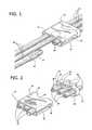
- FIG. 1is a perspective view of an illustrative embodiment of a fluid conduit connector apparatus in accordance with the principles of the present disclosure
- FIG. 2is a perspective view of a first and second connector according to an illustrative embodiment of the fluid conduit connector apparatus of the present disclosure
- FIG. 3is a side partial cross-sectional view of the illustrative fluid conduit connector apparatus shown in FIG. 1 ;
- FIG. 4is a top cross sectional view of the illustrative fluid conduit connector apparatus shown in FIG. 1 ;
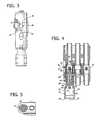
- FIG. 5is front cross sectional view of the coupling port in an illustrative fluid conduit connector apparatus according to the present disclosure
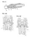
- FIG. 6is a side cross sectional perspective view of the fluid conduit connector apparatus according to an illustrative embodiment of the present disclosure
- FIG. 6Ais a cutaway perspective view of the fluid conduit connector apparatus shown in FIG. 6 ;
- FIG. 6Bis a cutaway perspective view of the fluid conduit connector apparatus shown in FIG. 6 ;
- FIG. 7is an exploded view of the various components of an illustrative fluid conduit connector apparatus according to the present disclosure.
- FIG. 8is an exploded view of the various components of an illustrative first connector in a fluid conduit connector apparatus according to the present disclosure
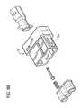
- FIG. 8Ais a perspective view of an alternate embodiment of the first connector shown in FIG. 8 ;
- FIG. 8Bis a perspective view of the first connector shown in FIG. 8A and an alternate embodiment of the second connector shown in FIG. 2 ;
- FIG. 8Cis a cross-sectional plan view of the first connector and the second connector shown in FIG. 8B ;
- FIG. 9is a side view of an illustrative coupling fitting according to the present disclosure.
- FIG. 10is a top view of a first or second connector including a detent cavity according to an illustrative embodiment of the present disclosure
- FIG. 11is a front view of a first or second connector including an interference rib according to an illustrative embodiment of the present disclosure
- FIG. 12is a front view of webbed tubing having an increased webbing volume according to an illustrative embodiment of the present.
- FIG. 13is an end view of a first or second connector including an interference key according to an illustrative embodiment of the present disclosure
- FIG. 14is a schematic view of two embodiments of a first connector and two embodiments of a second connector.
- FIG. 15is a diagrammatic view of a controller and fluid pressure source used with the fluid conduit connector apparatus.
- the exemplary embodiments of the fluid conduit connector apparatus and methods of operation disclosedare discussed in terms of prophylaxis compression apparatus and vascular therapy including a prophylaxis compression apparatus for application to a limb of a body and more particularly in terms of a compression apparatus having removable portions. It is envisioned that the present disclosure, however, finds application with a wide variety of pneumatic systems having removable fluid conduits, such as, for example, medical and industrial applications requiring timed sequences of compressed air in a plurality of air tubes.
- proximalrefers to a portion of a structure that is closer to a torso of a subject and the term “distal” refers to a portion that is further from the torso.
- distalrefers to a portion that is further from the torso.
- subjectrefers to a patient undergoing vascular therapy using the prophylaxis sequential compression apparatus.
- the term “practitioner”refers to an individual administering the prophylaxis sequential compression apparatus and may include support personnel.
- FIGS. 1 and 2there is illustrated a fluid conduit connector apparatus 10 , constructed in accordance with the principals of the present disclosure.
- the fluid conduit connector apparatus 10includes a connector having a first connector 12 and second connector 14 .
- First connector 12is configured for removable engagement with a second connector 14 .
- the first connector 12includes a first plurality of fluid ports 16 extending proximally therefrom and adapted for receiving a first plurality of fluid conduits 18 .
- Fluid conduits 18are connected to a compression apparatus, including for example, a compression sleeve 19 (see FIG. 15 ) adapted for disposal and treatment about a limb of a subject (not shown).
- the second connector 14includes a second plurality of fluid ports 20 extending distally therefrom and adapted for receiving a second plurality of fluid conduits 22 .
- Fluid conduits 22fluidly communicate with a pressurized fluid source 23 that is adapted to inflate the compression sleeve via the advantageous configuration of fluid conduit connector apparatus 10 , as described in accordance with the principles of the present disclosure.
- the pressurized fluid source 23is controlled by a controller 25 that includes instructions providing a timed sequence of the pressurized fluid to the compression sleeve 19 .
- conduits 18 , 22may include various tubing such as, for example, non-webbed tubing, etc.
- the fluid ports 16 , 20 of connectors 12 , 14respectively, each define an inner fluid orifice or passageway that facilitate fluid communication between connectors 12 , 14 .
- connectors 12 , 14facilitate fluid communication between the pressurized fluid source and the compression sleeve.
- the fluid conduit connector apparatus 10is illustrated as having a set of three fluid ports in each connector for connecting sets of three fluid conduits, it is contemplated that each connector can have any number of fluid ports without departing from the scope of the present disclosure.
- the first connector 12includes a sleeve 24 defining a cavity 26 having a distal opening.
- the cavity 26houses distal portions of the first plurality of fluid ports 16 which extend distally within the cavity 26 .
- the second connector 14includes a plurality of fluid couplings 28 extending proximally therefrom.
- the plurality of fluid couplings 28is formed by proximal portions of the second plurality of fluid ports 20 for alignment with the distal portions of the first plurality of fluid ports 16 .
- a locking arm 30extends proximally from the body portion 32 of the second connector 14 .
- a slot 34 in the sleeve 24 of first connector 12includes a window 36 adapted for removably accepting the locking arm 30 to retain the first connector 12 to the second connector 14 .
- At least one of the first plurality of portsis a coupling port 38 adapted for receiving a coupling fitting 40 .
- the coupling fitting 40is permanently attached to the distal end of a corresponding one of the first plurality of fluid conduits 18 .
- a locking tab extending radially from the coupling fitting 40is configured for engaging a detent cavity 44 in the first connector 12 , for example in the sleeve 24 as shown in FIG. 1 .
- a streamlined outer surface 25prevents the connectors from snagging on patient clothing or bedding.
- FIGS. 3-7the various components of the fluid conduit connector apparatus will be described in further detail.
- a gasket 46conforms to the space between the plurality of couplings 28 and the distal portion of the first plurality of fluid ports 16 within the cavity 26 when the first 12 is engaged with the second connector 14 .
- the gasket 46provides sealing for pressurized fluid communication between corresponding fluid conduits by providing a sealed fluid channel including the first plurality of fluid ports and second plurality of fluid ports. It is envisioned that the gasket 46 can be efficiently and inexpensively manufactured using a variety of common materials or fabrication methods, for example by injection molding an elastomeric material or dye cutting a cork or paper based gasket material. It is envisioned that the gasket 46 can be configured for retention to one or the other of the first connector 12 and second connector 14 .
- the gasketincludes a proximal lip 48 configured to engage the distal portion of each of the first plurality of fluid ports to provide fluid sealing between the first connector 12 and the second connector 14 .
- the gasketincludes a retention portion extending therefrom.
- the sleeve 24includes a gasket retention groove adapted to accept the retention portion and thereby retain the gasket to the sleeve 24 when the second connector 14 is removed therefrom.
- the slot 34at least partially bifurcates the sleeve 24 to allow spreading of the sleeve 24 under stress when the locking arm 30 is pressed into the slot 34 at its distal end as the first connector 12 is mated to the second connector 14 .
- an engagement portion 48 of the locking arm 30reaches the window portion 36 of the slot 34 the sleeve returns to its relaxed shape to releasably retain the second connector 14 by its locking arms 30 .
- the locking arm 48is formed with a leading surface 39 inclined at an angle (i.e., first angle) and a trailing surface 41 inclined at a second angle.
- the leading surface 39is inclined at a shallower angle than the trailing 41 surface so that the force to connect the first connector 12 to the second connector 14 is lighter than the force to disconnect the first connector 12 from the second connector 14 .
- Predetermined connection/disconnection forcescan thereby be achieved by proper selection of the first and second angle when designing a particular locking arm 48 .
- first connector 12includes a locking arm 234 that is configured for mating engagement with corresponding slot 230 formed in second connector 14 , similar to the arm and slot structure described.
- An alignment rib 59( FIG. 1 ) extends radially from at least one of the plurality of couplings 28 along its longitudinal axis.
- a corresponding alignment slot(not shown) is provided in the inner surface of the sleeve 24 extending to the distal end thereof for accepting the alignment rib 59 . It is contemplated that virtually any type of alignment rib/slot configuration commonly used in the art of for alignment of mating connectors can be used without departing from the scope of the present disclosure.
- the coupling fitting 40includes a proximal cylinder 52 and a distal cylinder 54 aligned along a longitudinal axis 56 .
- the proximal cylinder 52includes a proximal opening 58 and an inside diameter 60 defining an inner surface 62 configured for a press fit corresponding to the outside diameter of one of the first plurality of fluid conduits 18 .
- the corresponding fluid conduitis an air tube which is press fit into the proximal cylinder 52 through its proximal opening 58 .
- the fluid conduitis substantially permanently attached to the proximal cylinder 52 by friction.
- a variety of suitable adhesivesmay be applied to the inner surface 62 of the proximal cylinder 52 to permanently attach the fluid conduit and provide a fluid tight seal therebetween.
- a silicon adhesive, rubber cement, a material specific adhesive compound, an o-ring, a gasket or the likecan be used according to methods well known in the art to attach the fluid conduit to the coupling fitting.
- the distal cylinder 54comprises an inner surface defined by an inside contour 64 revolved about the longitudinal axis 56 and an outer surface 66 defined by an outside diameter.
- the inside contour 64includes a sealing portion 68 , a flexing portion 70 and an annular lip portion 72 .
- the sealing portion 68has an inside diameter adapted for a tight fit against the outside surface of the coupling port 38 to provide at least partial fluid sealing therebetween.
- the annular lip portion 72defines an annular ring that compresses against the outside surface of coupling port 38 and provides fluid sealing therebetween.
- the flexing portion 70is defined by a reduced wall thickness which allows the distal cylinder 54 to deflect inwardly to facilitate engagement of the locking tab 42 to the detent cavity 44 .
- the sleeve 24 or interior surface of the first connector 12can include a detent cavity 44 extending at least partially into the interior surface and adapted for accepting the locking tab 42 of the coupling fitting 40 .
- a detent 57 of tab 42is inserted into sleeve 24 to become disposed in cavity 44 .
- Detent 57is rotated through cavity 44 , via manipulation of fitting 40 and retained in position by bump formed in the wall of cavity 44 .
- the detent cavity shown in FIG. 10includes a longitudinal track portion 55 (shown in phantom) adapted for guiding the locking tab 42 ( FIG. 9 ) during engagement and disengagement and an annular portion 57 adapted for retaining the locking tab 42 ( FIG.
- the detent cavity 44can have varying depth or width into the interior surface.
- the varying depth of the detent cavity 44provides a predetermined engagement/disengagement force/displacement profile between the locking tab 42 and the detent cavity.
- the locking tabhas an outer portion with an enlarged manual engagement surface 43 to assist manipulation of the locking tab 42 .
- the coupling fittingincludes an engagement portion 74 adapted for opening a valve 76 disposed within the coupling port 38 .
- the engagement portion 74extends distally from a transverse wall 78 within the coupling fitting 40 to displace a plunger 80 in the valve 76 .
- the transverse wall 78is disposed within the coupling fitting 40 about between the proximal cylinder 52 and the distal cylinder 54 and orthogonal to the longitudinal axis 56 . At least one fluid passageway extends through the transverse wall.
- valve engagement structurecan be used to displace a valve plunger 80 within the scope of the present disclosure.
- a flat surface of the transverse wall 78 or a rib extending from the inner surface of the distal cylinder 54can be aligned with a complementary structure within a valve 76 to displace a valve plunger 80 when the coupling fitting 40 is engaged with the coupling port 38 .
- the illustrative embodimentincludes a valve 76 is disposed within the coupling port 38 .
- the valve 76includes a plunger 80 movable along the longitudinal axis of the coupling port 38 and biased proximally by a spring 82 .
- the spring 82is supported by the gasket 46 which is held in place in cavity 26 by protrusion 51 on the gasket 46 . Adhesive may alternatively be used to maintain gasket 46 in position.
- the gasket 46includes a spring seat formed along the longitudinal axis of any gasket passageway to be aligned with a coupling port. ( FIGS. 4-5 )
- the spring seat in the illustrative embodimentincludes a central stub 84 supported by radial spars 86 within the gasket opening.
- the valvecan be easily assembled by installing the spring 82 over the distal end of the plunger 80 to form a plunger and spring sub-assembly.
- the plunger 80includes a step 88 to engage the proximal end of the spring 82 .
- the plunger and spring sub-assemblycan then be installed into the coupling port 38 from its proximal end.
- the gasket 46can then be installed into the cavity 26 .
- the plunger and spring sub-assemblycan be installed to the gasket 46 by fitting the spring 82 to the spring seat before installing the gasket 46 spring 82 and plunger 80 together to the first connector 12 .
- FIGS. 7 and 8provide two illustrative embodiments of a plunger 80 according to the present disclosure.
- the present disclosureillustrates the use of a coil spring 82 to bias the plunger 80
- spring forcecould be applied to the plunger 80 by forming a plastic cantilever spring arm that could be formed within the first connector 12 .
- a structure similar to the spring seatcould be formed of elastomeric material as part of the gasket 46 to provide a biasing force to the plunger 80 without departing from the scope of the present disclosure.
- a portion of the compression sleeve that fluidly communicates with the pressurized fluid source via coupling port 38may be removed from the remainder of the compression sleeve.
- the remaining portion of the compression sleevecontinues to provide treatment to the limb of the subject.
- the coupling fitting 40is disconnected and not engaged to the coupling port 38 .
- Spring 82forces the plunger 80 to its proximal limit of travel where the plunger 80 engages a proximal stop such that valve 76 is in a closed position.
- the plunger 80is configured to cooperate with an internal structure in the coupling port 38 to define a reduced fluid orifice when the plunger 80 is displaced to its proximal limit.
- the reduced fluid orificeis designed to provide pneumatic characteristics approximating the pneumatic characteristics of a detached device.
- a cap 90 having a fluid passageway 92 therethroughis disposed in the proximal opening of the coupling port 38 .
- the cap 90provides a stop defining a proximal limit of plunger travel and is configured to cooperate with the plunger 80 of valve 76 , such that valve 76 reduces the dimension of the fluid orifice of coupling port 38 .
- coupling fitting 40is connected to the coupling port 38 to force plunger 80 distally and open the fluid connection ( FIG. 6A ), described above, for inflating a removable portion of an inflatable compression sleeve (not shown).
- a valve seat 282 of plunger 80is disposed via spring 82 (not shown in FIGS. 6A and 6B for clarity), out of engagement with a conical seat 284 of cap 90 .
- This configurationallows air to flow around the conical seat 284 and through conduit 22 (not shown), and out to the inflatable removable portion of the compression sleeve, as shown by arrows A.
- coupling fitting 40For removal of the removable portion of the compression sleeve, coupling fitting 40 is removed from coupling port 38 .
- Spring 82forces valve seat 282 into engagement with a counter bore edge of conical seat 284 .
- this configurationadvantageously reduces the dimension of the fluid orifice of coupling port 38 such that air only flows through cavities defined by semi-circular slots 286 of valve seat 282 and the bore edge of conical seat 284 .
- Slots 286are formed on the sides of valve seat 282 .
- the cavities defined by slots 286 and conical seat 284facilitate fluid flow that approximates the pneumatic behavior of the removable portion of the compression sleeve when coupling fitting 40 is connected to coupling port 38 during an open fluid connection.
- the cavities defined by slots 286 and conical seat 284may have various configurations and dimensions including geometries such as, for example, elliptical, polygonal, etc.
- the fluid orifice of coupling port 38may be variously configured such that corresponding engagement with plunger 80 reduces the orifice dimension to approximate fluid flow through coupling port 38 that would otherwise occur with valve 76 in the open position. It is further contemplated that plunger 80 may includes openings to approximate fluid flow. It is envisioned that valve 76 is operable to reduce the dimension of the fluid orifice of coupling port 38 over a range of closed positions, including partial fluid flow, leakage, etc. to approximate fluid in the port or alternatively, the orifice may completely close to prevent fluid flow through the corresponding port. In a completely closed configuration, pump speed or other settings may be adjusted.
- the present disclosureprovides an air tubing connector for use with a compression apparatus having removable portions, see, for example, the compression sleeve described in U.S. Pat. No. 7,282,038, filed on Feb. 23, 2004 and entitled Compression Apparatus.
- Three separate air tubeare connected to an ankle portion, a calf portion and a knee portion of the apparatus. Each portion is supplied with a timed sequence of compressed air through its respective air tube.
- the proximal end of each of the three air tubesis connected to the first plurality of fluid ports 16 in a first connector 12 according to the present disclosure.
- a mating set of three air tubesextends from a timed pressure source and is connected to the second plurality of fluid ports 18 in a second connector 14 according to the present disclosure.
- the distal end of the thigh tubeis connected to the first connector 12 via a coupling fitting 40 and port 38 as described hereinbefore.
- the thigh portioncan be removed and the tubing attached thereto can be disconnected from the first connector at the coupling port 38 .
- Operation of the valve 76 in the coupling port 38provides a reduced fluid orifice that restricts airflow therethrough to approximate the pneumatic characteristics of the thigh portion and its corresponding air tube.
- sensors in the timed pressure sourcewill not detect a change in fluid pressure or flow rate when the thigh portion is removed. This allows the timed pressure source to continue supplying uninterrupted timed air pressure to the ankle and calf portions of the prophylaxis compression apparatus.
- the first plurality of fluid conduits 18is a set of webbed tubing 98 having increased webbing volume 100 between at least one pair of adjacent conduits.
- At least one interference rib 94is formed between at least one pair of adjacent fluid ports in the first plurality of fluid ports.
- the increased webbing volume 100is aligned with the interference rib 94 if the set of webbed tubing 98 is improperly oriented with the first connector 12 .
- the interference rib 94thereby prevents attachment of improperly oriented fluid conduits to the first connector 12 .
- the second plurality of fluid conduits 22can include an increased webbing volume configured to interfere with an interference rib between adjacent ports in the second connector 14 to prevent attachment of improperly oriented fluid conduits to the second connector 14 .
- one embodimentincludes a first connector 12 having an interference key 96 in the cavity 26 to prevent the first connector 12 from mating with legacy connector components.
- the second connector 14includes a clearance space for the interference key 96 .
- FIG. 14schematically depicts the function of an interference key 96 to prevent connection of certain embodiments of a first connector 12 to certain embodiments of a second connector 13 .
- key slot 98 in second connector 13 Bprovides clearance for interference key 96 in first connector 12 B to facilitate mating one to the other.
- Second connector 13 Bcan also be mated to certain first connectors such as 12 A which do not include an interference key.
- Second connector 13 Adoes not include a key slot and therefore can not be mated with first connector 12 B.
- second connector 13 Ais a legacy connector.
- the interference key 96 in a non-compatible connector such as first connector 12 Bis used to prevent connection of the non-compatible connector to the legacy connector.
- the connector of the present disclosuremay be used with various single and plural bladder compression sleeve devices including, for example, the compression sleeve described in U.S. Pat. No. 7,282,038, filed on Feb. 23, 2004 and entitled Compression Apparatus, the entire contents of which is hereby incorporated by reference herein. Therefore, the above description should not be construed as limiting, but merely as exemplification of the various embodiments. Those skilled in the art will envision other modifications within the scope and spirit of the claims appended hereto.
Landscapes
- Health & Medical Sciences (AREA)
- Engineering & Computer Science (AREA)
- Heart & Thoracic Surgery (AREA)
- General Engineering & Computer Science (AREA)
- Hematology (AREA)
- Biomedical Technology (AREA)
- Anesthesiology (AREA)
- Life Sciences & Earth Sciences (AREA)
- Animal Behavior & Ethology (AREA)
- General Health & Medical Sciences (AREA)
- Public Health (AREA)
- Veterinary Medicine (AREA)
- Pulmonology (AREA)
- Mechanical Engineering (AREA)
- Infusion, Injection, And Reservoir Apparatuses (AREA)
Abstract
Description
Claims (12)
Priority Applications (1)
| Application Number | Priority Date | Filing Date | Title |
|---|---|---|---|
| US12/837,742US8256459B2 (en) | 2004-02-23 | 2010-07-16 | Fluid conduit connector apparatus |
Applications Claiming Priority (3)
| Application Number | Priority Date | Filing Date | Title |
|---|---|---|---|
| US10/784,639US7490620B2 (en) | 2004-02-23 | 2004-02-23 | Fluid conduit connector apparatus |
| US12/371,837US7810519B2 (en) | 2004-02-23 | 2009-02-16 | Fluid conduit connector apparatus |
| US12/837,742US8256459B2 (en) | 2004-02-23 | 2010-07-16 | Fluid conduit connector apparatus |
Related Parent Applications (1)
| Application Number | Title | Priority Date | Filing Date |
|---|---|---|---|
| US12/371,837ContinuationUS7810519B2 (en) | 2004-02-23 | 2009-02-16 | Fluid conduit connector apparatus |
Publications (2)
| Publication Number | Publication Date |
|---|---|
| US20100276619A1 US20100276619A1 (en) | 2010-11-04 |
| US8256459B2true US8256459B2 (en) | 2012-09-04 |
Family
ID=34861497
Family Applications (3)
| Application Number | Title | Priority Date | Filing Date |
|---|---|---|---|
| US10/784,639Expired - LifetimeUS7490620B2 (en) | 2004-02-23 | 2004-02-23 | Fluid conduit connector apparatus |
| US12/371,837Expired - Fee RelatedUS7810519B2 (en) | 2004-02-23 | 2009-02-16 | Fluid conduit connector apparatus |
| US12/837,742Expired - Fee RelatedUS8256459B2 (en) | 2004-02-23 | 2010-07-16 | Fluid conduit connector apparatus |
Family Applications Before (2)
| Application Number | Title | Priority Date | Filing Date |
|---|---|---|---|
| US10/784,639Expired - LifetimeUS7490620B2 (en) | 2004-02-23 | 2004-02-23 | Fluid conduit connector apparatus |
| US12/371,837Expired - Fee RelatedUS7810519B2 (en) | 2004-02-23 | 2009-02-16 | Fluid conduit connector apparatus |
Country Status (1)
| Country | Link |
|---|---|
| US (3) | US7490620B2 (en) |
Cited By (16)
| Publication number | Priority date | Publication date | Assignee | Title |
|---|---|---|---|---|
| US20110315244A1 (en)* | 2010-06-29 | 2011-12-29 | Sumitomo Wiring Systems, Ltd. | Gas distribution unit |
| US10391019B2 (en) | 2007-04-13 | 2019-08-27 | Stryker Corporation | Patient support with universal energy supply system |
| US10667984B2 (en) | 2015-12-18 | 2020-06-02 | Stryker Corporation | Systems and methods for operating patient therapy devices |
| US10707741B2 (en) | 2017-07-18 | 2020-07-07 | Polaris Industries Inc. | Voltage generator and a method of making a voltage generator |
| US10998665B2 (en) | 2018-11-15 | 2021-05-04 | Medline Industries, Inc. | Hybrid connector |
| US20220154864A1 (en)* | 2020-11-16 | 2022-05-19 | Colder Products Company | Fluid handling couplings |
| US11410771B2 (en) | 2017-06-01 | 2022-08-09 | Stryker Corporation | Patient care devices with open communication |
| USD1026221S1 (en) | 2020-03-03 | 2024-05-07 | Fisher & Paykel Healthcare Limited | Connector for a respiratory system conduit |
| USD1027165S1 (en) | 2016-06-10 | 2024-05-14 | Fisher & Paykel Healthcare Limited | Connector for a breathing circuit |
| USD1037433S1 (en) | 2019-09-10 | 2024-07-30 | Fisher & Paykel Healthcare Limited | Connector for a breathing conduit |
| USD1039134S1 (en) | 2021-06-11 | 2024-08-13 | Fisher & Paykel Healthcare Limited | Tube assembly and connector |
| US12115317B2 (en) | 2015-09-04 | 2024-10-15 | Fisher &Paykel Healthcare Limited | Connectors for conduits |
| USD1054555S1 (en) | 2020-12-09 | 2024-12-17 | Fisher & Paykel Healthcare Limited | Conduit connector |
| US12201776B2 (en) | 2015-03-31 | 2025-01-21 | Fisher & Paykel Healthcare Limited | Apparatus for use in a respiratory support system |
| US12203579B2 (en) | 2020-11-16 | 2025-01-21 | Colder Products Company | Fluid handling couplings |
| USD1073919S1 (en) | 2021-05-17 | 2025-05-06 | Fisher & Paykel Healthcare Limited | Respiratory system conduit with connector |
Families Citing this family (57)
| Publication number | Priority date | Publication date | Assignee | Title |
|---|---|---|---|---|
| US7354410B2 (en) | 2004-02-23 | 2008-04-08 | Tyco Healthcare Group Lp | Compression treatment system |
| US7490620B2 (en)* | 2004-02-23 | 2009-02-17 | Tyco Healthcare Group Lp | Fluid conduit connector apparatus |
| US7896910B2 (en)* | 2004-05-17 | 2011-03-01 | Coolsystems, Inc. | Modular apparatus for therapy of an animate body |
| US20080066897A1 (en)* | 2006-05-31 | 2008-03-20 | Sunbather Pty Ltd | Heat exchange manifold connector |
| US8257286B2 (en) | 2006-09-21 | 2012-09-04 | Tyco Healthcare Group Lp | Safety connector apparatus |
| US7837638B2 (en)* | 2007-02-13 | 2010-11-23 | Coolsystems, Inc. | Flexible joint wrap |
| US8092409B2 (en)* | 2007-05-18 | 2012-01-10 | Tyco Healthcare Group Lp | Reinforced connector |
| USD601248S1 (en) | 2007-05-18 | 2009-09-29 | Tyco Healthcare Group Lp | Connector and port arrangement with cylindrical segment tube retainers |
| USD595845S1 (en) | 2007-05-18 | 2009-07-07 | Tyco Healthcare Group Lp | Connector and port arrangement with arcuate tube retainers |
| US7731244B2 (en)* | 2007-09-12 | 2010-06-08 | Coolsystems, Inc. | Make-brake connector assembly with opposing latches |
| US20090121476A1 (en)* | 2007-11-08 | 2009-05-14 | The Government Of The Us, As Represented By The Secretary Of The Navy | Microfluidic Bus for Interconnecting Multiple Fluid Conduits |
| US8257287B2 (en) | 2008-03-20 | 2012-09-04 | Tyco Healthcare Group Lp | Safety connector assembly |
| AU2008358361A1 (en)* | 2008-06-26 | 2009-12-30 | Mack Trucks, Inc. | Shimmed joint, gasket for a shimmed joint, and method for sealing a shimmed joint |
| US8177734B2 (en)* | 2008-09-30 | 2012-05-15 | Tyco Healthcare Group Lp | Portable controller unit for a compression device |
| US8535253B2 (en)* | 2008-09-30 | 2013-09-17 | Covidien Lp | Tubeless compression device |
| US20100145421A1 (en)* | 2008-12-05 | 2010-06-10 | Coolsystems, Inc. | Therapeutic Cooling and/or Heating System Including A Thermo-Conductive Material |
| US20100139294A1 (en)* | 2008-12-05 | 2010-06-10 | Coolsystems, Inc. | Cooling System Having A Bypass Valve To Regulate Fluid Flow |
| EP3714848A1 (en) | 2009-10-22 | 2020-09-30 | Coolsystems, Inc. | Temperature and flow control methods in a thermal therapy device |
| WO2011057016A2 (en)* | 2009-11-04 | 2011-05-12 | Coolsystems, Inc. | System for providing treatment to a mammal |
| US8394043B2 (en) | 2010-02-12 | 2013-03-12 | Covidien Lp | Compression garment assembly |
| US9615967B2 (en) | 2010-12-30 | 2017-04-11 | Coolsystems, Inc. | Reinforced therapeutic wrap and method |
| US8597217B2 (en) | 2010-12-30 | 2013-12-03 | Coolsystems, Inc. | Reinforced therapeutic wrap and method |
| EP2689766A4 (en)* | 2011-03-25 | 2014-09-10 | Terumo Corp | Double-ended needle and mixing instrument |
| JP6121994B2 (en) | 2011-06-08 | 2017-04-26 | ネクステージ メディカル インコーポレイテッド | Fluid coupling system |
| US10463565B2 (en) | 2011-06-17 | 2019-11-05 | Coolsystems, Inc. | Adjustable patient therapy device |
| US9649459B2 (en) | 2011-09-26 | 2017-05-16 | Resmed Paris Sas | Ventilator apparatus and method |
| US10828402B2 (en)* | 2011-10-14 | 2020-11-10 | Alcon Inc. | Collar connector |
| EP3035997B1 (en)* | 2013-08-21 | 2018-04-11 | Cedic S.r.l. | Needlefree valve device |
| US10456320B2 (en) | 2013-10-01 | 2019-10-29 | Coolsystems, Inc. | Hand and foot wraps |
| USD743510S1 (en)* | 2013-10-31 | 2015-11-17 | Nordson Corporation | High pressure fluid conduit connector components and connector assembly |
| US9534721B2 (en)* | 2013-10-31 | 2017-01-03 | Nordson Corporation | High pressure fluid conduit connector components and connector assembly |
| US10080877B2 (en)* | 2014-07-25 | 2018-09-25 | Warsaw Orthopedic, Inc. | Drug delivery device and methods having a drug cartridge |
| US9775978B2 (en) | 2014-07-25 | 2017-10-03 | Warsaw Orthopedic, Inc. | Drug delivery device and methods having a retaining member |
| US20160038336A1 (en) | 2014-08-05 | 2016-02-11 | Tamara L. HILTON | Integrated multisectional heat exchanger |
| SE541088C2 (en)* | 2015-11-24 | 2019-04-02 | Munkplast Ab | Portable sampling device for collecting particles from exhaled breath |
| US10076650B2 (en) | 2015-11-23 | 2018-09-18 | Warsaw Orthopedic, Inc. | Enhanced stylet for drug depot injector |
| US9802740B2 (en)* | 2015-12-08 | 2017-10-31 | Jeff Ray Schunk | Storage tank hatch liner |
| US10124308B2 (en)* | 2015-12-31 | 2018-11-13 | Baxter Corporation Englewood | Apparatus and system for improved set-up of multi-ingredient compounder |
| US10859295B2 (en) | 2016-04-13 | 2020-12-08 | ZeoThermal Technologies, LLC | Cooling and heating platform |
| USD802756S1 (en) | 2016-06-23 | 2017-11-14 | Warsaw Orthopedic, Inc. | Drug pellet cartridge |
| US10434261B2 (en) | 2016-11-08 | 2019-10-08 | Warsaw Orthopedic, Inc. | Drug pellet delivery system and method |
| US10743670B2 (en)* | 2017-05-23 | 2020-08-18 | Yeti Coolers, Llc | Portable chair and cup holder assembly |
| US10561249B2 (en) | 2017-05-23 | 2020-02-18 | Yeti Coolers, Llc | Portable chair and cup holder assembly |
| USD850810S1 (en) | 2018-01-10 | 2019-06-11 | Yeti Coolers, Llc | Portable chair |
| CN108567564B (en)* | 2018-02-12 | 2021-02-02 | 泉州台商投资区双艺商贸有限公司 | Physical training device with leg muscle relaxing performance |
| KR102179175B1 (en)* | 2019-03-11 | 2020-11-16 | (주)선메딕스 | Movable air massage apparatus |
| US11857491B2 (en) | 2019-03-13 | 2024-01-02 | Breg, Inc. | Integrated cold therapy-compression therapy assembly and associated treatment protocols |
| EP3952976A4 (en) | 2019-04-09 | 2022-12-28 | NxStage Medical, Inc. | Methods, devices, and systems for coupling fluid lines |
| US10737049B1 (en)* | 2019-08-05 | 2020-08-11 | Dynasthetics, Llc | Apparatus for connecting oxygen delivery control instrument to patient delivery device |
| US12054337B2 (en) | 2019-08-27 | 2024-08-06 | Jeff Ray Schunk | Storage tank isolation system |
| CA3151262A1 (en) | 2019-10-30 | 2021-05-06 | Daryl ANACLETO | Dual port pneumatic connector |
| USD963161S1 (en)* | 2020-05-22 | 2022-09-06 | Kpr U.S., Llc | Fluid connector |
| US11293576B2 (en)* | 2020-08-31 | 2022-04-05 | Caremed Supply Inc. | Gas supply connector |
| US11986592B2 (en) | 2021-05-14 | 2024-05-21 | Dynasthetics, Llc | Electronic firebreak systems and methods for use with oxygen delivery device |
| USD1001248S1 (en)* | 2021-05-24 | 2023-10-10 | Kpr U.S., Llc | Fluid connector |
| USD1001249S1 (en)* | 2021-05-24 | 2023-10-10 | Kpr U.S., Llc | Fluid connector |
| USD993406S1 (en)* | 2021-05-24 | 2023-07-25 | Kpr U.S., Llc | Fluid connector |
Citations (103)
| Publication number | Priority date | Publication date | Assignee | Title |
|---|---|---|---|---|
| US950263A (en)* | 1909-05-26 | 1910-02-22 | Fred H Harpster | Automatic pipe-coupling for cars. |
| US1608239A (en) | 1925-12-09 | 1926-11-23 | Rosett Joshua | Therapeutic device |
| US1670318A (en) | 1925-03-09 | 1928-05-22 | William H Keller Inc | Governor for pressure-fluid-operated tools |
| US1695848A (en) | 1924-11-01 | 1928-12-18 | Westinghouse Lamp Co | Gas economizer |
| US1883240A (en) | 1925-11-27 | 1932-10-18 | Honeywell Regulator Co | Magnetically operated valve |
| US2280485A (en) | 1942-04-21 | Calculating device | ||
| US2628850A (en) | 1949-03-19 | 1953-02-17 | Donald V Summerville | Releasable conduit connection with automatic valving |
| US2638915A (en) | 1950-12-13 | 1953-05-19 | Mbg Corp | Fluid coupling |
| US2694395A (en) | 1951-05-10 | 1954-11-16 | William J Brown | Pneumatic pressure garment |
| US3057001A (en) | 1958-06-23 | 1962-10-09 | Illinois Tool Works | Strain relief grommet |
| US3287031A (en) | 1964-09-21 | 1966-11-22 | William H Simmons | Indexed keyed connection |
| US3469863A (en) | 1967-04-05 | 1969-09-30 | Trico Products Corp | Fluid coupling assembly |
| US3728875A (en) | 1971-01-07 | 1973-04-24 | Kendall & Co | Stocking with soft inner thigh area |
| US3733577A (en) | 1970-02-16 | 1973-05-15 | Bunker Ramo | Electrical two-part connectors |
| US4013069A (en) | 1975-10-28 | 1977-03-22 | The Kendall Company | Sequential intermittent compression device |
| US4029087A (en) | 1975-10-28 | 1977-06-14 | The Kendall Company | Extremity compression device |
| US4030488A (en) | 1975-10-28 | 1977-06-21 | The Kendall Company | Intermittent compression device |
| US4066084A (en) | 1974-01-14 | 1978-01-03 | Hans Tillander | Blood emptying device |
| US4091804A (en) | 1976-12-10 | 1978-05-30 | The Kendall Company | Compression sleeve |
| US4156425A (en) | 1977-08-10 | 1979-05-29 | The Kendall Company | Protective compression sleeve |
| US4198961A (en) | 1979-01-12 | 1980-04-22 | The Kendall Company | Compression device with sleeve retained conduits |
| US4207876A (en) | 1979-01-12 | 1980-06-17 | The Kendall Company | Compression device with ventilated sleeve |
| US4207875A (en) | 1979-01-12 | 1980-06-17 | The Kendall Company | Compression device with knee accommodating sleeve |
| US4253449A (en) | 1979-08-09 | 1981-03-03 | The Kendall Company | Compression device with connection system |
| US4280485A (en) | 1980-04-11 | 1981-07-28 | The Kendall Company | Compression device with simulator |
| US4355632A (en) | 1980-08-06 | 1982-10-26 | Jobst Institute, Inc. | Anti-shock pressure garment |
| US4580816A (en) | 1984-01-25 | 1986-04-08 | E. R. Squibb & Sons, Inc. | Quick disconnect tube coupling |
| US4624248A (en) | 1983-02-07 | 1986-11-25 | David Clark Company Incorporated | Transparent pressure garment |
| US4696289A (en) | 1983-06-22 | 1987-09-29 | Electro-Biology, Inc. | Method of promoting venous pump action |
| US4754993A (en) | 1986-10-28 | 1988-07-05 | Handy & Harman Automotive Group, Inc. | Conduit harness connector assembly |
| US4762504A (en) | 1986-02-19 | 1988-08-09 | Molex Incorporated | Connector coupling lock |
| US4762121A (en) | 1981-08-14 | 1988-08-09 | Mego Afek, Industrial Measuring Instruments | Massaging sleeve for body limbs |
| US4804208A (en) | 1986-08-11 | 1989-02-14 | The Kendall Company | Manifold coupling assembly |
| USRE32939E (en) | 1983-06-22 | 1989-06-06 | Electro-Biology, Inc. | Medical appliance |
| US4867699A (en) | 1988-04-06 | 1989-09-19 | Amp Incorporated | Connector with checking device |
| US4872736A (en) | 1988-04-19 | 1989-10-10 | American Telephone And Telegraph Company, At&T Bell Laboratories | Connector assembly having a latching mechanism |
| US5007411A (en) | 1989-04-12 | 1991-04-16 | The Kendall Company | Device for applying compressive pressures against a patient's limb |
| US5022387A (en) | 1987-09-08 | 1991-06-11 | The Kendall Company | Antiembolism stocking used in combination with an intermittent pneumatic compression device |
| US5031604A (en) | 1989-04-12 | 1991-07-16 | The Kendall Company | Device for applying compressive pressures to a patient's limb |
| US5041025A (en) | 1990-01-31 | 1991-08-20 | Thomas & Betts Corporation | Interconnectable components employing a multi-positionable key |
| US5176406A (en) | 1990-12-20 | 1993-01-05 | Straghan Robert G | Coupling |
| US5186163A (en) | 1991-11-25 | 1993-02-16 | The Kendall Company | Compression device |
| US5211192A (en) | 1991-11-14 | 1993-05-18 | Jorgensen William F | Pneumatic pressure relief assembly |
| US5217384A (en) | 1991-07-26 | 1993-06-08 | Merit-Elektrik Gmbh | Mechanical locking on plug connection between electrical switch and connecting plug |
| US5219185A (en) | 1990-11-13 | 1993-06-15 | Itw Fastex Italia S.P.A. | Snap-on fluidtight pipe connecting device |
| US5249830A (en) | 1990-02-02 | 1993-10-05 | Etablissements Caillau | Device for locking two coaxial tubes |
| US5273254A (en) | 1992-07-23 | 1993-12-28 | Huron Products Industries, Inc. | Fluid conduit quick connectors with anti-spill valves |
| US5312083A (en) | 1992-05-07 | 1994-05-17 | Thure Ekman | Arrangement in a media-conducting unit |
| US5330366A (en) | 1992-08-04 | 1994-07-19 | Yazaki Corporation | Connector with unlocking member |
| US5354260A (en) | 1993-05-13 | 1994-10-11 | Novamedix, Ltd. | Slipper with an inflatable foot pump |
| US5370423A (en) | 1992-02-28 | 1994-12-06 | Guest; John D. | Tube couplings |
| US5383894A (en) | 1993-07-30 | 1995-01-24 | The Kendall Co. | Compression device having stepper motor controlled valves |
| US5387110A (en) | 1993-11-12 | 1995-02-07 | International Business Machines Corporation | Reversible dual media adapter cable |
| USD357736S (en) | 1993-09-16 | 1995-04-25 | The Kendall Company | Connector for device for applying compressive pressure to the leg |
| US5435009A (en) | 1992-10-01 | 1995-07-25 | Huntleigh Technology Plc | Inflatable compression garment |
| US5437610A (en) | 1994-01-10 | 1995-08-01 | Spinal Cord Society | Extremity pump apparatus |
| US5443289A (en) | 1992-11-11 | 1995-08-22 | Guest; John D. | Tube couplings |
| USD363988S (en) | 1994-04-26 | 1995-11-07 | The Kendall Company | Connector for applying compressive pressure to the leg |
| US5478119A (en) | 1993-09-16 | 1995-12-26 | The Kendall Company | Polarized manifold connection device |
| US5575762A (en) | 1994-04-05 | 1996-11-19 | Beiersdorf-Jobst, Inc. | Gradient sequential compression system and method for reducing the occurrence of deep vein thrombosis |
| US5588955A (en) | 1993-07-08 | 1996-12-31 | Aircast, Inc. | Method and apparatus for providing therapeutic compression for reducing risk of DVT |
| US5588954A (en) | 1994-04-05 | 1996-12-31 | Beiersdorf-Jobst, Inc. | Connector for a gradient sequential compression system |
| US5591200A (en) | 1994-06-17 | 1997-01-07 | World, Inc. | Method and apparatus for applying pressure to a body limb for treating edema |
| US5626556A (en) | 1994-07-26 | 1997-05-06 | The Kendall Company | Hook and loop attachment for a compression sleeve and method of attaching a hook and loop fastener to a compression sleeve |
| GB2313784A (en) | 1996-06-07 | 1997-12-10 | Medical Dynamics Limited | Device for facilitating blood circulation in the lower limbs |
| US5711757A (en) | 1993-10-20 | 1998-01-27 | Neoligaments Limited | Controller especially for pneumatic continuous passive motion devices |
| US5743755A (en) | 1995-12-22 | 1998-04-28 | Yazaki Corporation | Connector system |
| US5795312A (en) | 1993-09-27 | 1998-08-18 | The Kendall Company | Compression sleeve |
| EP0861651A1 (en) | 1991-12-17 | 1998-09-02 | Kinetic Concepts, Inc. | Pneumatic compression device and methods for use in the medical field |
| US5843007A (en) | 1996-04-29 | 1998-12-01 | Mcewen; James Allen | Apparatus and method for periodically applying a pressure waveform to a limb |
| US5876359A (en) | 1994-11-14 | 1999-03-02 | Bock; Malcolm G. | Sequential compression device controller |
| US5881769A (en) | 1995-12-19 | 1999-03-16 | Snap-Tite Technologies, Inc. | Breakaway coupling |
| US5897142A (en) | 1996-12-19 | 1999-04-27 | Itt Automotive, Inc. | Push-to-release quick connector |
| US5989204A (en) | 1991-09-27 | 1999-11-23 | Kinetic Concepts, Inc. | Foot-mounted venous compression device |
| US5988704A (en) | 1996-01-02 | 1999-11-23 | Aba Of Sweden Ab | Hose coupling device |
| US5997495A (en) | 1995-04-08 | 1999-12-07 | Novamedix Distribution Ltd | Medical device for the hand |
| US6007559A (en) | 1998-06-12 | 1999-12-28 | Aci Medical | Vascular assist methods and apparatus |
| DE19846922A1 (en) | 1998-10-12 | 2000-04-20 | Manuel Fernandez | Medical treatment device for venous and lymphatic disease; has several chambers that can be individually inflated under computer-assisted control |
| US6062244A (en) | 1998-08-13 | 2000-05-16 | Aci Medical | Fluidic connector |
| US6105933A (en) | 1994-06-29 | 2000-08-22 | Kabushiki-Kaisha Motoyama Seisakusho | Diaphragm valve structure |
| US6129688A (en) | 1996-09-06 | 2000-10-10 | Aci Medical | System for improving vascular blood flow |
| US6152495A (en) | 1996-12-20 | 2000-11-28 | Mannesmann Vdo Ag | Hose coupling for connecting a hose with a second component |
| US6231532B1 (en) | 1998-10-05 | 2001-05-15 | Tyco International (Us) Inc. | Method to augment blood circulation in a limb |
| US6238230B1 (en) | 2000-08-15 | 2001-05-29 | Telefonaktiebolaget L.M. Ericsson | Latch assembly and connector assembly including the same |
| US6257626B1 (en) | 1999-04-27 | 2001-07-10 | Flow-Rite Controls, Ltd. | Connector for fluid handling system |
| US6257627B1 (en) | 1999-03-24 | 2001-07-10 | Nifco Inc. | Tube connectable to pipe |
| US6290662B1 (en) | 1999-05-28 | 2001-09-18 | John K. Morris | Portable, self-contained apparatus for deep vein thrombosis (DVT) prophylaxis |
| US6319215B1 (en) | 1999-07-29 | 2001-11-20 | Medical Dynamics Usa, Llc | Medical device for applying cyclic therapeutic action to a subject's foot |
| US6394131B1 (en) | 2000-11-16 | 2002-05-28 | Abb Offshore Systems, Inc. | Trapped fluid volume compensator for hydraulic couplers |
| US6423053B1 (en) | 2000-01-12 | 2002-07-23 | Han-Pin Lee | Releasable tube assembly |
| US6436064B1 (en) | 1999-04-30 | 2002-08-20 | Richard J. Kloecker | Compression garment for selective application for treatment of lymphedema and related illnesses manifested at various locations of the body |
| US6468237B1 (en) | 1991-12-17 | 2002-10-22 | Kinetic Concepts, Inc. | Pneumatic pump, housing and methods for medical purposes |
| US6494852B1 (en) | 1998-03-11 | 2002-12-17 | Medical Compression Systems (Dbn) Ltd. | Portable ambulant pneumatic compression system |
| US6537099B2 (en) | 2001-08-22 | 2003-03-25 | Delphi Technologies, Inc. | Tamper proof electrical connector |
| US6544202B2 (en) | 1998-08-12 | 2003-04-08 | Mcewen James Allen | Apparatus and method for applying an adaptable pressure waveform to a limb |
| US6547284B2 (en) | 1999-04-08 | 2003-04-15 | Med-Eng Systems Inc. | Automatic or manual quick release latch |
| US20030075923A1 (en) | 2001-10-24 | 2003-04-24 | Wecosta | Air filter, intake duct and assembly consisting of a filter and an intake duct of this kind |
| US6592534B1 (en) | 1999-12-27 | 2003-07-15 | Aircast, Inc. | Inflatable medical appliance for prevention of DVT |
| US6629941B1 (en) | 1998-12-28 | 2003-10-07 | Nitto Kohki Co., Ltd. | Air massage system |
| WO2004011842A1 (en) | 2002-07-27 | 2004-02-05 | Jwl Maskin-Og Plastfabrik A/S | Rapid coupling device and method for assembling a coupling socket |
| US6890204B2 (en) | 2001-07-31 | 2005-05-10 | Yazaki Corporation | Locking mechanism for connector |
| US7478840B2 (en) | 2001-01-23 | 2009-01-20 | Cable Management Products Limited | Pipe couplings |
| US7490620B2 (en) | 2004-02-23 | 2009-02-17 | Tyco Healthcare Group Lp | Fluid conduit connector apparatus |
Family Cites Families (3)
| Publication number | Priority date | Publication date | Assignee | Title |
|---|---|---|---|---|
| US357736A (en)* | 1887-02-15 | Thomas smith | ||
| US32939A (en)* | 1861-07-30 | |||
| US2694393A (en) | 1951-07-11 | 1954-11-16 | William E Simpson | Weed burner |
- 2004
- 2004-02-23USUS10/784,639patent/US7490620B2/ennot_activeExpired - Lifetime
- 2009
- 2009-02-16USUS12/371,837patent/US7810519B2/ennot_activeExpired - Fee Related
- 2010
- 2010-07-16USUS12/837,742patent/US8256459B2/ennot_activeExpired - Fee Related
Patent Citations (108)
| Publication number | Priority date | Publication date | Assignee | Title |
|---|---|---|---|---|
| US2280485A (en) | 1942-04-21 | Calculating device | ||
| US950263A (en)* | 1909-05-26 | 1910-02-22 | Fred H Harpster | Automatic pipe-coupling for cars. |
| US1695848A (en) | 1924-11-01 | 1928-12-18 | Westinghouse Lamp Co | Gas economizer |
| US1670318A (en) | 1925-03-09 | 1928-05-22 | William H Keller Inc | Governor for pressure-fluid-operated tools |
| US1883240A (en) | 1925-11-27 | 1932-10-18 | Honeywell Regulator Co | Magnetically operated valve |
| US1608239A (en) | 1925-12-09 | 1926-11-23 | Rosett Joshua | Therapeutic device |
| US2628850A (en) | 1949-03-19 | 1953-02-17 | Donald V Summerville | Releasable conduit connection with automatic valving |
| US2638915A (en) | 1950-12-13 | 1953-05-19 | Mbg Corp | Fluid coupling |
| US2694395A (en) | 1951-05-10 | 1954-11-16 | William J Brown | Pneumatic pressure garment |
| US3057001A (en) | 1958-06-23 | 1962-10-09 | Illinois Tool Works | Strain relief grommet |
| US3287031A (en) | 1964-09-21 | 1966-11-22 | William H Simmons | Indexed keyed connection |
| US3469863A (en) | 1967-04-05 | 1969-09-30 | Trico Products Corp | Fluid coupling assembly |
| US3733577A (en) | 1970-02-16 | 1973-05-15 | Bunker Ramo | Electrical two-part connectors |
| US3728875A (en) | 1971-01-07 | 1973-04-24 | Kendall & Co | Stocking with soft inner thigh area |
| US4066084A (en) | 1974-01-14 | 1978-01-03 | Hans Tillander | Blood emptying device |
| US4030488A (en) | 1975-10-28 | 1977-06-21 | The Kendall Company | Intermittent compression device |
| US4029087A (en) | 1975-10-28 | 1977-06-14 | The Kendall Company | Extremity compression device |
| US4013069A (en) | 1975-10-28 | 1977-03-22 | The Kendall Company | Sequential intermittent compression device |
| US4091804A (en) | 1976-12-10 | 1978-05-30 | The Kendall Company | Compression sleeve |
| US4156425A (en) | 1977-08-10 | 1979-05-29 | The Kendall Company | Protective compression sleeve |
| US4198961A (en) | 1979-01-12 | 1980-04-22 | The Kendall Company | Compression device with sleeve retained conduits |
| US4207876A (en) | 1979-01-12 | 1980-06-17 | The Kendall Company | Compression device with ventilated sleeve |
| US4207875A (en) | 1979-01-12 | 1980-06-17 | The Kendall Company | Compression device with knee accommodating sleeve |
| US4253449A (en) | 1979-08-09 | 1981-03-03 | The Kendall Company | Compression device with connection system |
| US4280485A (en) | 1980-04-11 | 1981-07-28 | The Kendall Company | Compression device with simulator |
| US4355632A (en) | 1980-08-06 | 1982-10-26 | Jobst Institute, Inc. | Anti-shock pressure garment |
| US4762121A (en) | 1981-08-14 | 1988-08-09 | Mego Afek, Industrial Measuring Instruments | Massaging sleeve for body limbs |
| US4624248A (en) | 1983-02-07 | 1986-11-25 | David Clark Company Incorporated | Transparent pressure garment |
| US4696289A (en) | 1983-06-22 | 1987-09-29 | Electro-Biology, Inc. | Method of promoting venous pump action |
| US4696289B1 (en) | 1983-06-22 | 1999-10-12 | Novamedix Ltd | Method of stimulating the venous-pump of the foot and for enchancement of arterial flow to the foot |
| USRE32939F1 (en) | 1983-06-22 | 2002-07-09 | Novamedix Distrib Ltd | Medical appliance for artificial actuation of the venous-pump mechanism in a human foot |
| US4696289C1 (en) | 1983-06-22 | 2002-09-03 | Novamedix Distrib Ltd | Method of stimulating the venous-pump mechanism of the foot and for enhancement of arterial flow to the foot |
| USRE32939E (en) | 1983-06-22 | 1989-06-06 | Electro-Biology, Inc. | Medical appliance |
| US4580816A (en) | 1984-01-25 | 1986-04-08 | E. R. Squibb & Sons, Inc. | Quick disconnect tube coupling |
| US4762504A (en) | 1986-02-19 | 1988-08-09 | Molex Incorporated | Connector coupling lock |
| US4804208A (en) | 1986-08-11 | 1989-02-14 | The Kendall Company | Manifold coupling assembly |
| US4754993A (en) | 1986-10-28 | 1988-07-05 | Handy & Harman Automotive Group, Inc. | Conduit harness connector assembly |
| US5022387A (en) | 1987-09-08 | 1991-06-11 | The Kendall Company | Antiembolism stocking used in combination with an intermittent pneumatic compression device |
| US4867699A (en) | 1988-04-06 | 1989-09-19 | Amp Incorporated | Connector with checking device |
| US4872736A (en) | 1988-04-19 | 1989-10-10 | American Telephone And Telegraph Company, At&T Bell Laboratories | Connector assembly having a latching mechanism |
| US5031604A (en) | 1989-04-12 | 1991-07-16 | The Kendall Company | Device for applying compressive pressures to a patient's limb |
| US5007411A (en) | 1989-04-12 | 1991-04-16 | The Kendall Company | Device for applying compressive pressures against a patient's limb |
| US5041025A (en) | 1990-01-31 | 1991-08-20 | Thomas & Betts Corporation | Interconnectable components employing a multi-positionable key |
| US5249830A (en) | 1990-02-02 | 1993-10-05 | Etablissements Caillau | Device for locking two coaxial tubes |
| US5219185A (en) | 1990-11-13 | 1993-06-15 | Itw Fastex Italia S.P.A. | Snap-on fluidtight pipe connecting device |
| US5176406A (en) | 1990-12-20 | 1993-01-05 | Straghan Robert G | Coupling |
| US5217384A (en) | 1991-07-26 | 1993-06-08 | Merit-Elektrik Gmbh | Mechanical locking on plug connection between electrical switch and connecting plug |
| US5989204A (en) | 1991-09-27 | 1999-11-23 | Kinetic Concepts, Inc. | Foot-mounted venous compression device |
| US5211192A (en) | 1991-11-14 | 1993-05-18 | Jorgensen William F | Pneumatic pressure relief assembly |
| US5186163A (en) | 1991-11-25 | 1993-02-16 | The Kendall Company | Compression device |
| US6468237B1 (en) | 1991-12-17 | 2002-10-22 | Kinetic Concepts, Inc. | Pneumatic pump, housing and methods for medical purposes |
| EP0861651A1 (en) | 1991-12-17 | 1998-09-02 | Kinetic Concepts, Inc. | Pneumatic compression device and methods for use in the medical field |
| US5370423A (en) | 1992-02-28 | 1994-12-06 | Guest; John D. | Tube couplings |
| US5312083A (en) | 1992-05-07 | 1994-05-17 | Thure Ekman | Arrangement in a media-conducting unit |
| US5273254A (en) | 1992-07-23 | 1993-12-28 | Huron Products Industries, Inc. | Fluid conduit quick connectors with anti-spill valves |
| US5330366A (en) | 1992-08-04 | 1994-07-19 | Yazaki Corporation | Connector with unlocking member |
| US5435009A (en) | 1992-10-01 | 1995-07-25 | Huntleigh Technology Plc | Inflatable compression garment |
| US5443289A (en) | 1992-11-11 | 1995-08-22 | Guest; John D. | Tube couplings |
| US5354260A (en) | 1993-05-13 | 1994-10-11 | Novamedix, Ltd. | Slipper with an inflatable foot pump |
| US5588955A (en) | 1993-07-08 | 1996-12-31 | Aircast, Inc. | Method and apparatus for providing therapeutic compression for reducing risk of DVT |
| US5383894A (en) | 1993-07-30 | 1995-01-24 | The Kendall Co. | Compression device having stepper motor controlled valves |
| USD357736S (en) | 1993-09-16 | 1995-04-25 | The Kendall Company | Connector for device for applying compressive pressure to the leg |
| US5478119A (en) | 1993-09-16 | 1995-12-26 | The Kendall Company | Polarized manifold connection device |
| US5795312A (en) | 1993-09-27 | 1998-08-18 | The Kendall Company | Compression sleeve |
| US5711757A (en) | 1993-10-20 | 1998-01-27 | Neoligaments Limited | Controller especially for pneumatic continuous passive motion devices |
| US5387110A (en) | 1993-11-12 | 1995-02-07 | International Business Machines Corporation | Reversible dual media adapter cable |
| US5437610A (en) | 1994-01-10 | 1995-08-01 | Spinal Cord Society | Extremity pump apparatus |
| US5951502A (en) | 1994-04-05 | 1999-09-14 | Kci New Technologies, Inc. | Gradient sequential compression system for preventing deep vein thrombosis |
| US5588954A (en) | 1994-04-05 | 1996-12-31 | Beiersdorf-Jobst, Inc. | Connector for a gradient sequential compression system |
| US5575762A (en) | 1994-04-05 | 1996-11-19 | Beiersdorf-Jobst, Inc. | Gradient sequential compression system and method for reducing the occurrence of deep vein thrombosis |
| USD363988S (en) | 1994-04-26 | 1995-11-07 | The Kendall Company | Connector for applying compressive pressure to the leg |
| US5591200A (en) | 1994-06-17 | 1997-01-07 | World, Inc. | Method and apparatus for applying pressure to a body limb for treating edema |
| US6105933A (en) | 1994-06-29 | 2000-08-22 | Kabushiki-Kaisha Motoyama Seisakusho | Diaphragm valve structure |
| US5626556A (en) | 1994-07-26 | 1997-05-06 | The Kendall Company | Hook and loop attachment for a compression sleeve and method of attaching a hook and loop fastener to a compression sleeve |
| US5876359A (en) | 1994-11-14 | 1999-03-02 | Bock; Malcolm G. | Sequential compression device controller |
| US5997495A (en) | 1995-04-08 | 1999-12-07 | Novamedix Distribution Ltd | Medical device for the hand |
| US5881769A (en) | 1995-12-19 | 1999-03-16 | Snap-Tite Technologies, Inc. | Breakaway coupling |
| US5743755A (en) | 1995-12-22 | 1998-04-28 | Yazaki Corporation | Connector system |
| US5988704A (en) | 1996-01-02 | 1999-11-23 | Aba Of Sweden Ab | Hose coupling device |
| US6440093B1 (en) | 1996-04-29 | 2002-08-27 | Mcewen James Allen | Apparatus and method for monitoring pneumatic limb compression therapy |
| US5843007A (en) | 1996-04-29 | 1998-12-01 | Mcewen; James Allen | Apparatus and method for periodically applying a pressure waveform to a limb |
| GB2313784A (en) | 1996-06-07 | 1997-12-10 | Medical Dynamics Limited | Device for facilitating blood circulation in the lower limbs |
| US6129688A (en) | 1996-09-06 | 2000-10-10 | Aci Medical | System for improving vascular blood flow |
| US5897142A (en) | 1996-12-19 | 1999-04-27 | Itt Automotive, Inc. | Push-to-release quick connector |
| US6152495A (en) | 1996-12-20 | 2000-11-28 | Mannesmann Vdo Ag | Hose coupling for connecting a hose with a second component |
| US6494852B1 (en) | 1998-03-11 | 2002-12-17 | Medical Compression Systems (Dbn) Ltd. | Portable ambulant pneumatic compression system |
| US6007559A (en) | 1998-06-12 | 1999-12-28 | Aci Medical | Vascular assist methods and apparatus |
| US6544202B2 (en) | 1998-08-12 | 2003-04-08 | Mcewen James Allen | Apparatus and method for applying an adaptable pressure waveform to a limb |
| US6062244A (en) | 1998-08-13 | 2000-05-16 | Aci Medical | Fluidic connector |
| US6231532B1 (en) | 1998-10-05 | 2001-05-15 | Tyco International (Us) Inc. | Method to augment blood circulation in a limb |
| DE19846922A1 (en) | 1998-10-12 | 2000-04-20 | Manuel Fernandez | Medical treatment device for venous and lymphatic disease; has several chambers that can be individually inflated under computer-assisted control |
| US6629941B1 (en) | 1998-12-28 | 2003-10-07 | Nitto Kohki Co., Ltd. | Air massage system |
| US6257627B1 (en) | 1999-03-24 | 2001-07-10 | Nifco Inc. | Tube connectable to pipe |
| US6547284B2 (en) | 1999-04-08 | 2003-04-15 | Med-Eng Systems Inc. | Automatic or manual quick release latch |
| US6257626B1 (en) | 1999-04-27 | 2001-07-10 | Flow-Rite Controls, Ltd. | Connector for fluid handling system |
| US6436064B1 (en) | 1999-04-30 | 2002-08-20 | Richard J. Kloecker | Compression garment for selective application for treatment of lymphedema and related illnesses manifested at various locations of the body |
| US6290662B1 (en) | 1999-05-28 | 2001-09-18 | John K. Morris | Portable, self-contained apparatus for deep vein thrombosis (DVT) prophylaxis |
| US6319215B1 (en) | 1999-07-29 | 2001-11-20 | Medical Dynamics Usa, Llc | Medical device for applying cyclic therapeutic action to a subject's foot |
| US6592534B1 (en) | 1999-12-27 | 2003-07-15 | Aircast, Inc. | Inflatable medical appliance for prevention of DVT |
| US6423053B1 (en) | 2000-01-12 | 2002-07-23 | Han-Pin Lee | Releasable tube assembly |
| US6238230B1 (en) | 2000-08-15 | 2001-05-29 | Telefonaktiebolaget L.M. Ericsson | Latch assembly and connector assembly including the same |
| US6394131B1 (en) | 2000-11-16 | 2002-05-28 | Abb Offshore Systems, Inc. | Trapped fluid volume compensator for hydraulic couplers |
| US7478840B2 (en) | 2001-01-23 | 2009-01-20 | Cable Management Products Limited | Pipe couplings |
| US6890204B2 (en) | 2001-07-31 | 2005-05-10 | Yazaki Corporation | Locking mechanism for connector |
| US6537099B2 (en) | 2001-08-22 | 2003-03-25 | Delphi Technologies, Inc. | Tamper proof electrical connector |
| US20030075923A1 (en) | 2001-10-24 | 2003-04-24 | Wecosta | Air filter, intake duct and assembly consisting of a filter and an intake duct of this kind |
| WO2004011842A1 (en) | 2002-07-27 | 2004-02-05 | Jwl Maskin-Og Plastfabrik A/S | Rapid coupling device and method for assembling a coupling socket |
| US7490620B2 (en) | 2004-02-23 | 2009-02-17 | Tyco Healthcare Group Lp | Fluid conduit connector apparatus |
Non-Patent Citations (10)
| Title |
|---|
| Kendall SCD, "Sequential Compression Sleeves", Patent information, Jan. 1993, 6 pages. |
| PCT International Search Report issued in Application No. PCT/US2005/005598, Jun. 2, 2005, 5 pages. |
| PCT International Search Report issued in Application No. PCT/US2005/005599, May 25, 2005, 4 pages. |
| PCT International Search Report issued in Application No. PCT/US2005/005600, Jun. 2, 2005, 7 pages. |
| PCT Invitation to Pay Additional Fees issued in Application No. PCT/US2005/005679, Jun. 10, 2005, 6 pages. |
| The Kendall Company, "The New SCD Compression Sleeve", Aug. 1993, pp. 1-2. |
| The Kendall Company, Vascular Therapy Products Catalog, Jan. 1996, pp. 8-5 through 8-7. |
| Tyco Healthcare Kendall, "Prevention Gets Personal", Mar. 2001, pp. 1, 2, 4. |
| Tyco Healthcare Kendall, SCD Response Catalog, Mar. 2000, pp. 1-2. |
| Tyco Healthcare Kendall, SCD Soft Sleeve Catalog, Apr. 2001, pp. 1-2. |
Cited By (21)
| Publication number | Priority date | Publication date | Assignee | Title |
|---|---|---|---|---|
| US10391019B2 (en) | 2007-04-13 | 2019-08-27 | Stryker Corporation | Patient support with universal energy supply system |
| US8727385B2 (en)* | 2010-06-29 | 2014-05-20 | Sumitomo Wiring Systems, Ltd. | Gas distribution unit |
| US20110315244A1 (en)* | 2010-06-29 | 2011-12-29 | Sumitomo Wiring Systems, Ltd. | Gas distribution unit |
| US12201776B2 (en) | 2015-03-31 | 2025-01-21 | Fisher & Paykel Healthcare Limited | Apparatus for use in a respiratory support system |
| US12115317B2 (en) | 2015-09-04 | 2024-10-15 | Fisher &Paykel Healthcare Limited | Connectors for conduits |
| US10667984B2 (en) | 2015-12-18 | 2020-06-02 | Stryker Corporation | Systems and methods for operating patient therapy devices |
| USD1027165S1 (en) | 2016-06-10 | 2024-05-14 | Fisher & Paykel Healthcare Limited | Connector for a breathing circuit |
| USD1028213S1 (en) | 2016-06-10 | 2024-05-21 | Fisher & Paykel Healthcare Limited | Connector for a breathing circuit |
| US11410771B2 (en) | 2017-06-01 | 2022-08-09 | Stryker Corporation | Patient care devices with open communication |
| US10707741B2 (en) | 2017-07-18 | 2020-07-07 | Polaris Industries Inc. | Voltage generator and a method of making a voltage generator |
| US10998665B2 (en) | 2018-11-15 | 2021-05-04 | Medline Industries, Inc. | Hybrid connector |
| USD918842S1 (en) | 2018-11-15 | 2021-05-11 | Medline Industries, Inc. | Connector |
| USD1037433S1 (en) | 2019-09-10 | 2024-07-30 | Fisher & Paykel Healthcare Limited | Connector for a breathing conduit |
| USD1074989S1 (en) | 2019-09-10 | 2025-05-13 | Fisher & Paykel Healthcare Limited | Connector for a breathing conduit |
| USD1026221S1 (en) | 2020-03-03 | 2024-05-07 | Fisher & Paykel Healthcare Limited | Connector for a respiratory system conduit |
| US11480280B2 (en)* | 2020-11-16 | 2022-10-25 | Colder Products Company | Fluid handling couplings |
| US20220154864A1 (en)* | 2020-11-16 | 2022-05-19 | Colder Products Company | Fluid handling couplings |
| US12203579B2 (en) | 2020-11-16 | 2025-01-21 | Colder Products Company | Fluid handling couplings |
| USD1054555S1 (en) | 2020-12-09 | 2024-12-17 | Fisher & Paykel Healthcare Limited | Conduit connector |
| USD1073919S1 (en) | 2021-05-17 | 2025-05-06 | Fisher & Paykel Healthcare Limited | Respiratory system conduit with connector |
| USD1039134S1 (en) | 2021-06-11 | 2024-08-13 | Fisher & Paykel Healthcare Limited | Tube assembly and connector |
Also Published As
| Publication number | Publication date |
|---|---|
| US20090146092A1 (en) | 2009-06-11 |
| US20100276619A1 (en) | 2010-11-04 |
| US7810519B2 (en) | 2010-10-12 |
| US20050184264A1 (en) | 2005-08-25 |
| US7490620B2 (en) | 2009-02-17 |
Similar Documents
| Publication | Publication Date | Title |
|---|---|---|
| US8256459B2 (en) | Fluid conduit connector apparatus | |
| CA2552354C (en) | Fluid conduit connector apparatus | |
| CN1918422B (en) | Fluid Pipe Connections | |
| US6062244A (en) | Fluidic connector | |
| US8257286B2 (en) | Safety connector apparatus | |
| EP1795168B1 (en) | Compression apparatus | |
| TWI413518B (en) | Control unit assembly | |
| CA1144024A (en) | Compression device with connection system | |
| US20110172692A1 (en) | Hemodialysis arterio-venous graft with a ring-like diameter-adjustable device | |
| US9713563B2 (en) | Micro bleed hole connector for use in intermittent pneumatic compression devices | |
| CN213218912U (en) | Antithrombotic pressure pump leg sleeve external fixation device | |
| WO2016118342A1 (en) | Sequential compression wrap connector and wrap | |
| US20170128658A1 (en) | Arteriovenous access valve system with separate valve tubes | |
| US5129916A (en) | System and method for driving venous blood from body extremity to prepare same for local anesthetic | |
| CA2133074A1 (en) | Exsanguinating to prepare extremity for anesthetic | |
| MX2008009132A (en) | Control unit assembly | |
| AU2314692A (en) | Exsanguinating to prepare extremity for anesthetic |
Legal Events
| Date | Code | Title | Description |
|---|---|---|---|
| AS | Assignment | Owner name:TYCO HEALTHCARE GROUP LP, MASSACHUSETTS Free format text:ASSIGNMENT OF ASSIGNORS INTEREST;ASSIGNORS:TESLUK, CHRISTOPHER;BOCK, MALCOLM;SIGNING DATES FROM 20040407 TO 20040409;REEL/FRAME:028029/0664 | |
| ZAAA | Notice of allowance and fees due | Free format text:ORIGINAL CODE: NOA | |
| ZAAB | Notice of allowance mailed | Free format text:ORIGINAL CODE: MN/=. | |
| STCF | Information on status: patent grant | Free format text:PATENTED CASE | |
| AS | Assignment | Owner name:COVIDIEN LP, MASSACHUSETTS Free format text:CHANGE OF NAME;ASSIGNOR:TYCO HEALTHCARE GROUP LP;REEL/FRAME:030427/0385 Effective date:20120928 | |
| FPAY | Fee payment | Year of fee payment:4 | |
| AS | Assignment | Owner name:KPR U.S., LLC, MASSACHUSETTS Free format text:ASSIGNMENT OF ASSIGNORS INTEREST;ASSIGNOR:COVIDIEN LP;REEL/FRAME:044128/0390 Effective date:20170728 | |
| MAFP | Maintenance fee payment | Free format text:PAYMENT OF MAINTENANCE FEE, 8TH YEAR, LARGE ENTITY (ORIGINAL EVENT CODE: M1552); ENTITY STATUS OF PATENT OWNER: LARGE ENTITY Year of fee payment:8 | |
| FEPP | Fee payment procedure | Free format text:MAINTENANCE FEE REMINDER MAILED (ORIGINAL EVENT CODE: REM.); ENTITY STATUS OF PATENT OWNER: LARGE ENTITY | |
| LAPS | Lapse for failure to pay maintenance fees | Free format text:PATENT EXPIRED FOR FAILURE TO PAY MAINTENANCE FEES (ORIGINAL EVENT CODE: EXP.); ENTITY STATUS OF PATENT OWNER: LARGE ENTITY | |
| STCH | Information on status: patent discontinuation | Free format text:PATENT EXPIRED DUE TO NONPAYMENT OF MAINTENANCE FEES UNDER 37 CFR 1.362 | |
| FP | Lapsed due to failure to pay maintenance fee | Effective date:20240904 |