US8256203B1 - Rocket based combined cycle propulsion unit having external rocket thrusters - Google Patents
Rocket based combined cycle propulsion unit having external rocket thrustersDownload PDFInfo
- Publication number
- US8256203B1 US8256203B1US12/021,142US2114208AUS8256203B1US 8256203 B1US8256203 B1US 8256203B1US 2114208 AUS2114208 AUS 2114208AUS 8256203 B1US8256203 B1US 8256203B1
- Authority
- US
- United States
- Prior art keywords
- rocket
- nozzle
- jet engine
- exhaust
- rbcc
- Prior art date
- Legal status (The legal status is an assumption and is not a legal conclusion. Google has not performed a legal analysis and makes no representation as to the accuracy of the status listed.)
- Expired - Fee Related, expires
Links
Images


Classifications
- F—MECHANICAL ENGINEERING; LIGHTING; HEATING; WEAPONS; BLASTING
- F02—COMBUSTION ENGINES; HOT-GAS OR COMBUSTION-PRODUCT ENGINE PLANTS
- F02K—JET-PROPULSION PLANTS
- F02K9/00—Rocket-engine plants, i.e. plants carrying both fuel and oxidant therefor; Control thereof
- F02K9/42—Rocket-engine plants, i.e. plants carrying both fuel and oxidant therefor; Control thereof using liquid or gaseous propellants
- F02K9/44—Feeding propellants
- F02K9/52—Injectors
- F—MECHANICAL ENGINEERING; LIGHTING; HEATING; WEAPONS; BLASTING
- F02—COMBUSTION ENGINES; HOT-GAS OR COMBUSTION-PRODUCT ENGINE PLANTS
- F02K—JET-PROPULSION PLANTS
- F02K1/00—Plants characterised by the form or arrangement of the jet pipe or nozzle; Jet pipes or nozzles peculiar thereto
- F02K1/002—Plants characterised by the form or arrangement of the jet pipe or nozzle; Jet pipes or nozzles peculiar thereto with means to modify the direction of thrust vector
- F02K1/004—Plants characterised by the form or arrangement of the jet pipe or nozzle; Jet pipes or nozzles peculiar thereto with means to modify the direction of thrust vector by using one or more swivable nozzles rotating about their own axis
- F—MECHANICAL ENGINEERING; LIGHTING; HEATING; WEAPONS; BLASTING
- F02—COMBUSTION ENGINES; HOT-GAS OR COMBUSTION-PRODUCT ENGINE PLANTS
- F02K—JET-PROPULSION PLANTS
- F02K3/00—Plants including a gas turbine driving a compressor or a ducted fan
- F02K3/02—Plants including a gas turbine driving a compressor or a ducted fan in which part of the working fluid by-passes the turbine and combustion chamber
- F02K3/025—Plants including a gas turbine driving a compressor or a ducted fan in which part of the working fluid by-passes the turbine and combustion chamber the by-pass flow being at least partly used to create an independent thrust component
- F—MECHANICAL ENGINEERING; LIGHTING; HEATING; WEAPONS; BLASTING
- F02—COMBUSTION ENGINES; HOT-GAS OR COMBUSTION-PRODUCT ENGINE PLANTS
- F02K—JET-PROPULSION PLANTS
- F02K7/00—Plants in which the working fluid is used in a jet only, i.e. the plants not having a turbine or other engine driving a compressor or a ducted fan; Control thereof
- F02K7/10—Plants in which the working fluid is used in a jet only, i.e. the plants not having a turbine or other engine driving a compressor or a ducted fan; Control thereof characterised by having ram-action compression, i.e. aero-thermo-dynamic-ducts or ram-jet engines
- F02K7/16—Composite ram-jet/turbo-jet engines
- F—MECHANICAL ENGINEERING; LIGHTING; HEATING; WEAPONS; BLASTING
- F02—COMBUSTION ENGINES; HOT-GAS OR COMBUSTION-PRODUCT ENGINE PLANTS
- F02K—JET-PROPULSION PLANTS
- F02K7/00—Plants in which the working fluid is used in a jet only, i.e. the plants not having a turbine or other engine driving a compressor or a ducted fan; Control thereof
- F02K7/10—Plants in which the working fluid is used in a jet only, i.e. the plants not having a turbine or other engine driving a compressor or a ducted fan; Control thereof characterised by having ram-action compression, i.e. aero-thermo-dynamic-ducts or ram-jet engines
- F02K7/18—Composite ram-jet/rocket engines
- F—MECHANICAL ENGINEERING; LIGHTING; HEATING; WEAPONS; BLASTING
- F02—COMBUSTION ENGINES; HOT-GAS OR COMBUSTION-PRODUCT ENGINE PLANTS
- F02K—JET-PROPULSION PLANTS
- F02K9/00—Rocket-engine plants, i.e. plants carrying both fuel and oxidant therefor; Control thereof
- F02K9/74—Rocket-engine plants, i.e. plants carrying both fuel and oxidant therefor; Control thereof combined with another jet-propulsion plant
- F02K9/78—Rocket-engine plants, i.e. plants carrying both fuel and oxidant therefor; Control thereof combined with another jet-propulsion plant with an air-breathing jet-propulsion plant
Definitions
- Combined Cycle Propulsionshows promise for next generation launch vehicles, missiles, and aircraft.
- a combined cycle systemincorporates several modes of engine operation into the same flow path.
- a launch vehicle powered by a typical Rocket Based Combined Cycle (RBCC) propulsion unitmay operate in an air-augmented rocket mode for takeoff and initial acceleration to around Mach 1.5, transition to ramjet operation until around Mach 4-6, and then transition to scramjet operation. Above around Mach 8-10, scramjet operation is presently unrealistic, and the engine may operate as a pure rocket to accelerate into orbit or for a high speed dash, as for example, with supersonic cruise missiles.
- the basic principleis to operate the engine in the propulsion mode that provides the highest specific impulse (Isp) for that flight condition.
- a rocket thrusteris integrated with and internally mounted in a jet engine in order to augment the thrust provided by the jet engine at lower speeds.
- the rocket thrusteraccelerates a vehicle to a velocity at which atmospheric air enters the engine with sufficient flow rate and pressure to mix and combust with the fuel rich rocket exhaust. These gas products are then exhausted through the remainder of the engine duct and a nozzle to produce thrust.
- the amount of onboard oxidizer and thus vehicle volumeis reduced, the mixing of the ingested air and fuel rich rocket exhaust can be an inefficient process that reduces overall performance.
- Additional downstream fuel injectionmay be implemented to supplement the rocket exhaust products.
- the internal rocket thrusteris turned off and the engine transitions to a pure ramjet mode.
- the incoming airis compressed to subsonic Mach numbers by shock waves in the engine inlet.
- Downstream RAM injectorssupply fuel that mixes with the air and is then ignited and sustains combustion at the flame holders.
- a range of injection points and a series of duct geometriesmay be desired as Mach number increases.
- the enginetransitions to scramjet mode. Scramjet operation is generally similar to a ramjet, except the inlet geometry is adjusted to reduce spillage of the incoming air, which remains supersonic through the engine.
- Another set of injectors and flame holdersare also used to provide adequate mixing and combustion.
- the increase in velocitycorresponds to an increase in altitude, such that around Mach 8-10 there is often insufficient air for scramjet operation.
- the external inletcan be closed and the internal rocket is operated to orbital altitude.
- the scramjet modeis not included, and the ramjet mode transitions directly to the pure rocket.
- external rocket enginesreplace the air-augmented internal rocket thruster. These rocket engines are attached to the vehicle and are not integrated with the jet engine.
- One problem with mounting a rocket engine external to the jet engineis that the rocket engine typically increases the vehicle cross-sectional area and thus the aerodynamic drag, especially in the transonic flight regime. More rocket engines may be desired to offset the increased drag, but adding rocket engines usually increases the cross-sectional area further.
- traditional rocket nozzles(often referred to as bell nozzles) do not usually operate efficiently over a wide altitude (and hence external pressure) range. Nozzles designed for the high altitude, pure rocket mode generally do not perform well at low altitudes. Bell nozzles that have the ability to compensate for altitude change are usually very complex, employing moving nozzle exhaust skirts. These additional features increase cost and weight, further complicate the packaging, and can lead to reduced reliability and life.
- FIG. 1illustrates an exemplary embodiment of a rocket based combined cycle (RBCC) propulsion unit.
- RBCCcombined cycle
- FIG. 2illustrates a tail of the RBCC propulsion unit depicted by FIG. 1 .
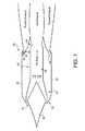
- FIG. 3illustrates a three-dimensional view of the tail depicted in FIG. 2 .
- FIG. 4is a block diagram illustrating an exemplary embodiment of a RBCC propulsion unit.
- FIG. 5is a block diagram illustrating an exemplary embodiment of a computer system employed by a RBCC propulsion unit, such as is depicted by FIG. 4 .
- FIG. 6illustrates a tail of an exemplary embodiment of a RBCC propulsion unit.
- FIG. 7illustrates a three-dimensional view of the tail depicted in FIG. 6 .
- the present disclosuregenerally pertains to rocket based combined cycle (RBCC) propulsion units.
- at least one rocket thrusteris integrated with a jet engine but is external to the flow path of the jet engine, forming an altitude compensating plug nozzle. Since the rocket thruster is external to such flow path, the rocket flow from the rocket thruster interacts with the jet flow from the jet engine aft of the nozzle of the jet engine. Such interaction occurs without a significant performance penalty in the operation of the jet engine. In fact, it is possible that the interaction of the rocket flow with the jet flow may actually improve the efficiency of the jet engine under some conditions. Moreover, having the rocket thrusters positioned external to the flow path of the jet engine helps to avoid many of the problems plaguing conventional RBCC propulsion units.
- a converging/diverging nozzleis used for a jet engine.
- Such nozzlewhich converges and diverges for the flow path of the jet engine, forms a plug nozzle for the rocket thrusters that are external to such flow path.
- the thrust provided by the rocket thrustersaugments the thrust of the jet engine and the plug nozzle rocket exhaust has intrinsic altitude compensation and can further compensate for altitude-related performance issues, such as over-expansion or under-expansion of the jet engine.
- the air-breathing enginee.g., ramjet, scramjet, turbo-ramjet
- the rocket thrustersare integrated into the nozzle region of a jet engine so as to reduce form drag and improve the rocket and ramjet flows, with less loss due to slip and shock interaction.
- This improvementcan be achieved by taking advantage of the shape of the ramjet/scramjet exhaust nozzle configuration to “nest” the rocket thrusters so that they are not a significant source of drag.
- Performancecan be improved by matching, to the extent feasible, the rocket and jet engine exhaust flow static pressures, while minimizing the angular changes in the flow field that produce irreversible shock interaction losses.
- a RBCC engineprovides efficient packaging, increased performance, weight reduction, low drag, and smooth engine operating mode transitions relative to many traditional RBCC configurations.
- FIG. 1depicts an exemplary embodiment of a RBCC propulsion unit 25 .
- the unit 25comprises a jet engine 30 , which can be similar to any conventional jet engine.
- the jet engine 30 shown by FIG. 1is a conventional ramjet engine.
- other types of known or future-developed air-breathing jet enginessuch as scramjet, turbojet, pulsejet, etc., are possible.
- the jet engine 30is implemented via a rocket engine instead of an air-breathing engine.
- the exemplary jet engine 30 shown by FIG. 1has an engine wall 33 that forms a flow path 35 through which air flows.
- the engine wall 33as well as the flow path 35 defined by the wall 33 , can have various shapes depending on the type of engine 30 being employed.
- the engine 30also has an inlet spike 38 , which can typically be adjusted to accommodate various flight conditions.
- the engine 30can be attached to various objects, such as airplanes or missiles, in order to provide thrust to such objects.
- the jet engine 30can have various sections depending on the engine type being employed.
- the engine 30includes an air intake 41 , an inlet throat 42 , a combustion chamber 43 , and a nozzle 44 .
- Airenters the jet engine 30 at the air intake 41 and flows through the throat 42 into the combustion chamber 43 .
- fuel injectorsinject fuel into air flowing through the path 35 , and the fuel is ignited and burns at the flame holders in the combustion chamber 43 .
- the tail of the engine 30forms a nozzle 44 .
- the cross-sectional area of the flow path 35begins to decrease after the combustion chamber 43 so that the exhaust from the combustion chamber 43 is accelerated through the engine tail or nozzle 44 .
- the nozzle 44is a converging/diverging nozzle.
- jet enginesincluding air-breathing as well as rocket engines, could be used to implement the engine 30 .
- each rocket thruster 52is positioned on an exterior of the engine wall 33 external to the flow path 35 .
- each rocket thruster 52is integral with the engine wall 33 .
- the engine wall 33forms the flow path through which exhaust from the rocket thruster 52 exits.
- the nozzle 44serves as a ramp for the exhaust of the rocket thrusters 52 .
- the exterior contour of the nozzle 44implements a plug nozzle for the exhaust flow from the rocket thrusters 52 .
- the nozzle 44implements a converging/diverging nozzle for the flow path 35 of the jet engine 30 and a plug nozzle for the exhaust flow from the rocket thrusters 52 .
- the exhaust flow of the rocket thrusters 52are substantially matched with the exhaust flow of the jet engine 30 .
- the exhaust velocity for each rocket thruster 52is controlled such that the static pressure of the exhaust flow of each rocket thruster 52 is approximately equal to the static pressure of the exhaust flow of the jet engine 30 .
- matching of the exhaust flows of the rocket thrusters 52 and the jet engine 30 to equalize static pressuresis unnecessary in all embodiments.
- each rocket thruster 52similar to the jet engine 30 , has a combustion chamber 56 into which fuel is injected and burned.
- Each thruster 52also has a converging/diverging nozzle 57 through which exhaust exits.
- the cross-sectional area of the flow path defining the combustion chamber 56decreases at the nozzle 57 thereby accelerating the rocket exhaust.
- the cross-sectional area of the flow paththen begins increasing allowing the rocket exhaust to expand and increase in velocity before exiting the thruster 52 .
- the rocket thrusters 52 and the jet engine 30can be selectively activated in order to achieve desired performance goals.
- the propulsion unit 25is attached to an aircraft, and the rocket thrusters 52 are activated during taxiing and/or take-off.
- the jet engine 30is activated and begins to provide thrust.
- the rocket thrusters 52can be deactivated or remain activated in order to augment the thrust provided by the jet engine 30 .
- the rocket thrusters 52can be selectively activated and deactivated depending on desired performance goals.
- the jet engine 30 and the rocket thrusters 52can be simultaneously activated, such as for short dash speeds, evasive maneuvers, high speed closing distances to increase kinetic energy at impact, etc.
- the rocket thrusters 52may be selectively activated based on various factors, such as altitude and/or airspeed.
- over-expansion and under-expansionare well known altitude-based problems suffered by many jet engines.
- the rocket thrusters 52may be deactivated.
- the rocket thrusters 52may be activated at altitudes for which the jet engine 30 operates inefficiently (e.g., when the jet engine 30 is operating at altitudes causing over-expansion or under-expansion). At altitudes for which the rocket thrusters 52 are activated, the jet engine 30 may continue to operate or may be deactivated, as may be desired. Moreover, the overall efficiency of the propulsion unit 25 may be enhanced via selective activation of the jet engine 30 and/or rocket thrusters 52 .
- the interaction of the exhaust flow from the rocket thrusters 52 and the exhaust flow from the jet engine 30can compensate for effects of over-expansion and possibly under-expansion of the jet engine 30 such that the thrust provided by the jet engine 30 is greater than the thrust that would have been provided in the absence of the exhaust flow from the rocket thrusters 52 .
- the exhaust flow from the rocket thrusters 52forms a boundary that helps limit the expansion of the exhaust flow from the jet engine 30 thereby improving the performance of the jet engine 30 , particularly when the exhaust flows of the rocket thrusters 52 and the jet engine 30 are matched.
- FIG. 4depicts a block diagram of an exemplary embodiment of a propulsion unit 25 .
- the jet engine 30 and the rocket thrusters 52are communicatively coupled to engine control logic 63 , which controls the activation states of the rocket thrusters 52 and the jet engine 30 based on various input, such as input from a user input interface 66 , an altimeter 67 , and/or an airspeed indicator 68 .
- Other types of input devicesare possible in other embodiments.
- the user input interface 66comprises any known or future-developed device or devices, such as a button, switch, keypad, lever, and/or other device, that allow a user to provide input.
- FIG. 4depicts three rocket thrusters 52 and one jet engine 30 , but other numbers of rocket thrusters 52 and/or jet engines 30 are possible.
- the engine control logic 63can be implemented in software, hardware, or a combination thereof.
- the engine control logic 63along with its associated methodology, is implemented in software and stored in memory 93 of a computer system 73 .
- the system 73comprises a processing element 74 , such as a central processing unit (CPU), which executes instructions of the engine control logic 63 , when such logic 63 is implemented in software.
- the processing element 74communicates to and drives the other elements within the system 73 via a local interface 75 , which can include at least one bus.
- an input/output (I/O) interface 76allows the logic 63 to exchange data with other components, such as the user input interface 66 , the altimeter 67 , the airspeed indicator 68 , the jet engine 30 , and the rocket thrusters 52 .
- engine control logic 63when implemented in software, can be stored and transported on any computer-readable medium for use by or in connection with an instruction execution apparatus that can fetch and execute instructions.
- a “computer-readable medium”can be any means that can store a program for use by or in connection with an instruction execution apparatus.
- the engine control logic 63can be configured to selectively control the activation states of the rocket thrusters 52 and the jet engine 30 in accordance with any desired algorithm. In this regard, the engine control logic 63 controls whether each thruster 52 and the jet engine 30 are activated and the extent to which the thrusters 52 and jet engine 30 are activated (i.e., the amount of thrust provided).
- An exemplary methodology for controlling the propulsion unit 25will be described below. It should be emphasized that other methodologies for controlling the unit 25 are possible.
- jet engine 30is a ramjet, as shown by FIG. 1 , and is used to provide thrust to an aircraft.
- the engine control logic 63activates the rocket thrusters 52 and deactivates the jet engine 30 .
- all of the thrust provided by the propulsion unit 25is via rocket thrusters 52 .
- the engine control logic 63receives, via the user input interface 66 , control input from a pilot or other user and, based on such input, controls the amount of thrust provided by the rocket thrusters 52 .
- the engine control logic 63activates the jet engine 30 .
- the engine control logic 63gradually throttles down the rocket thrusters 52 (i.e., decreases the thrust provided by the thrusters 52 ) while gradually throttling up the jet engine (i.e., increasing the thrust provided by the engine 30 ), until all of the thrust provided by the propulsion unit 25 is from the jet engine 30 .
- the transitioncan be automatically triggered based on input from the airspeed indicator 68 or other device, or the transition can be manually triggered via input received by the user input interface 66 . Other techniques for triggering and/or controlling the transition are also possible.
- the engine control logic 63activates the rocket thrusters 52 .
- the engine control logic 63gradually throttles down the jet engine 30 (i.e., decreases the thrust provided by the engine 30 ) while gradually throttling up the rocket thrusters 52 (i.e., increasing the thrust provided by the thrusters 52 ), until all of the thrust provided by the propulsion unit 25 is from the rocket thrusters 52 .
- the transitioncan be automatically triggered based on input from the airspeed indicator 68 or other device, or the transition can be manually triggered via input received by the user input interface 66 . Other techniques for triggering and/or controlling the transition are also possible.
- the transition process described abovecan be performed in reverse. That is, the engine control logic 63 transitions from rocket mode to ramjet mode when the speed of the aircraft falls below a certain airspeed, such as around Mach 5, and the engine control logic 63 transitions from ramjet mode to rocket mode when the speed of the aircraft falls below a certain airspeed, such as around Mach 1.5.
- the operation of the propulsion unit 25may also be controlled based on factors other than or in addition to airspeed.
- the engine control logic 63may control the activation states of the rocket thrusters 52 and jet engine 30 based on altitude. For example, at extremely high altitudes, such as over 70,000-80,000 feet, the density of the atmosphere is so low that operation of the jet engine 30 may not be feasible or may be inefficient. At some altitude, such as around 80,000 feet, the engine control logic 63 transitions from ramjet mode to rocket mode regardless of the airspeed. Such transition may be automatically triggered based on input from the altimeter 67 or other device, or the transition may be manually triggered based on input from the user input interface 66 .
- the engine control logic 63is be configured to operate simultaneously in the rocket mode and ramjet mode.
- the pilotprovides input via the user input interface 66 to control the amount of thrust provided by the jet engine 30 and the rocket thrusters 52 .
- the engine control logic 63intelligently controls the activation states based on inputs from the user input interface 66 , the altimeter 67 , and the airspeed indicator 68 .
- the engine control logic 63receives input from the user input interface 66 indicative of an amount of thrust that is desired.
- the engine control logic 63based on inputs from the altimeter 67 and the airspeed indicator 68 , then automatically determines how the rocket thrusters 52 and the jet engine 30 are to be controlled in order to efficiently deliver the desired thrust and desired flight profile.
- the engine control logic 63stores predefined data, referred to as “performance data” indicating how the propulsion is to be controlled based on various sets of input from the user input interface 66 , altimeter 67 , and airspeed indicator 68 .
- performance datamay be defined based on previous test results of the propulsion unit 25 or similar propulsion units in order to optimize the efficiency or performance of the unit 25 .
- the engine control logic 63looks up control information that is correlated with such keys.
- the control informationindicates how the thrusters 52 and the jet engine 30 are to be controlled for the flight conditions (e.g., altitude and airspeed) in order to provide the desired thrust, and the engine control logic 63 controls the propulsion unit 25 in accordance with such control information.
- the aircraftmay be at an airspeed for which ramjet operation is normally efficient in the absence of under-expansion or over-expansion.
- the aircraftmay be at an altitude that results in over-expansion or under-expansion thereby decreasing the efficiency of the jet engine 30 .
- itmay be desirable to supplement the thrust of the jet engine 30 with thrust from the rocket thrusters 52 .
- the engine control logic 63automatically determines the amount of thrust that is to be provided by the thrusters 52 and the jet engine 30 and controls the thrusters 52 and the jet engine 30 accordingly.
- the desired thrustis provided by a combination of the jet engine 30 and the rocket thrusters 52 .
- the rocket thrusters 52may have a higher efficiency than the jet engine 30 at the given altitude and airspeed such that the overall efficiency of the propulsion unit 25 is increased via activation of the rocket thrusters 52 .
- the rocket thrusters 52may help to compensate for the effects of over-expansion and/or under-expansion thereby increasing the efficiency of the jet engine 30 under certain operating conditions.
- FIGS. 6 and 7show an exemplary tail of a propulsion unit 25 having multiple exhaust ports 88 .
- Each portis for a respective jet engine.
- four jet enginesmay be accommodated.
- such jet enginesare integrated with one another, but it is possible for the jet engines to be non-integrated.
- the engine control logic 63is configured to selectively control activation of the rocket thrusters 52 to provide directional control for steering.
- the thrusters 52 on one side of the propulsion unit 25may be activated, and the thrusters 52 on the opposite side may be deactivated in order to turn the propulsion unit 25 and any object (e.g., aircraft) attached to it.
- the thrusters 52 on the bottom of the propulsion unit 25may be activated and the thrusters 52 on top of the unit 25 may be deactivated in order to increase the pitch of the unit 25 and any object (e.g., aircraft) attached to it.
- the thrusters 52 on the top of the propulsion unit 25may be activated and the thrusters 52 on the bottom of the unit 25 may be deactivated in order to decrease the pitch of the unit 25 and any object (e.g., airplane) attached to it. Rather than deactivating some of the thrusters 52 , it is possible for similar steering effects to be achieved by controlling the thrusters 52 such that some of the thrusters 52 provide greater thrust than other of the thrusters 52 .
- RBCC propulsion unitsthere are many different embodiments for RBCC propulsion units, which have various advantages and features depending on the embodiment employed.
- the propulsion unit 25can more smoothly transition between engine modes relative to some conventional RBCC configurations.
- Overall performance and/or efficiencycan be increased, and existing jet engines can be retrofitted with rocket thrusters.
- ramrocketswhich have combined flow paths, the losses associated with internal fluid dynamic interactions between the rocket exhaust and air-breathing combustion zone exhausts can be avoided.
- the overall performancecan be improved as a function of altitude by having the compensating plume expansion with changes in external pressure provided by a plug nozzle.
- the wake region drag associated with a typical aerospikecan be substantially reduced by using low-level air-breathing core flow for base bleed in the rocket mode and then using the full core flow plume in the air breathing engine mode.
- Overall vehicle form dragcan be greatly reduced when the rocket thrusters are not internal to the jet engine.
- the rocket thrusterscan be nested in the engine wall so that no additional cross-sectional area resulting from the presence of the rocket thrusters is exposed to air flow thereby reducing drag.
- a conventional ram/scramjet ductdoes not have to be enlarged to accommodate the rocket thrusters.
- the rocket thrusterscan be positioned on the throat region of an air-breathing engine.
Landscapes
- Engineering & Computer Science (AREA)
- Chemical & Material Sciences (AREA)
- Combustion & Propulsion (AREA)
- Mechanical Engineering (AREA)
- General Engineering & Computer Science (AREA)
- Testing Of Engines (AREA)
Abstract
Description
Claims (18)
Priority Applications (1)
| Application Number | Priority Date | Filing Date | Title |
|---|---|---|---|
| US12/021,142US8256203B1 (en) | 2007-01-26 | 2008-01-28 | Rocket based combined cycle propulsion unit having external rocket thrusters |
Applications Claiming Priority (2)
| Application Number | Priority Date | Filing Date | Title |
|---|---|---|---|
| US88668907P | 2007-01-26 | 2007-01-26 | |
| US12/021,142US8256203B1 (en) | 2007-01-26 | 2008-01-28 | Rocket based combined cycle propulsion unit having external rocket thrusters |
Publications (1)
| Publication Number | Publication Date |
|---|---|
| US8256203B1true US8256203B1 (en) | 2012-09-04 |
Family
ID=46726360
Family Applications (1)
| Application Number | Title | Priority Date | Filing Date |
|---|---|---|---|
| US12/021,142Expired - Fee RelatedUS8256203B1 (en) | 2007-01-26 | 2008-01-28 | Rocket based combined cycle propulsion unit having external rocket thrusters |
Country Status (1)
| Country | Link |
|---|---|
| US (1) | US8256203B1 (en) |
Cited By (19)
| Publication number | Priority date | Publication date | Assignee | Title |
|---|---|---|---|---|
| GB2519156A (en)* | 2013-10-11 | 2015-04-15 | Reaction Engines Ltd | A nozzle arrangement for an engine |
| US20150101342A1 (en)* | 2013-10-11 | 2015-04-16 | Reaction Engines Ltd | Engine |
| US20170030297A1 (en)* | 2014-03-26 | 2017-02-02 | Mitsubishi Heavy Industries, Ltd. | Combustor, jet engine, flying body, and operation method of jet engine |
| CN107061010A (en)* | 2017-03-23 | 2017-08-18 | 西北工业大学 | A kind of rocket based combined cycle engine structure changes air intake duct |
| CN108928505A (en)* | 2018-06-28 | 2018-12-04 | 上海卫星工程研究所 | The satellite powered phase method for exhausting controlled using satellite and the rocket pull-off plug signal |
| CN109101765A (en)* | 2018-09-19 | 2018-12-28 | 西北工业大学 | A kind of wide fast domain propulsion system modelling by mechanism method of big envelope curve of assembly power aircraft |
| CN110886668A (en)* | 2019-12-09 | 2020-03-17 | 北京动力机械研究所 | Ejection rocket deicing fire extinguishing system |
| CN111878253A (en)* | 2020-07-31 | 2020-11-03 | 中国人民解放军国防科技大学 | Wave-lobe rocket nozzle and rocket base combined circulating propulsion system |
| CN112228246A (en)* | 2020-10-30 | 2021-01-15 | 华中科技大学 | A rocket-based detonation ramjet combined cycle engine and its using method and application |
| CN112627984A (en)* | 2020-12-15 | 2021-04-09 | 中国人民解放军国防科技大学 | Axial-symmetric-structure self-adaptive pneumatically-adjusted RBCC engine and aircraft |
| CN112682218A (en)* | 2020-12-24 | 2021-04-20 | 中国人民解放军国防科技大学 | Wide-speed-range engine based on annular supercharging central body mixed section confluence rocket stamping |
| US11067036B2 (en) | 2014-03-26 | 2021-07-20 | Mitsubishi Heavy Industries, Ltd. | Combustor and jet engine having the same |
| CZ309478B6 (en)* | 2018-05-21 | 2023-02-15 | Jan Kvapil | Air-enhanced rocket nozzle |
| CN116335852A (en)* | 2023-02-07 | 2023-06-27 | 中国空气动力研究与发展中心空天技术研究所 | Stamping engine tail nozzle of integrated enhanced rocket and design and working methods thereof |
| US20230211900A1 (en)* | 2021-12-30 | 2023-07-06 | Blue Origin, Llc | Reusable upper stage rocket with aerospike engine |
| EP4323632A2 (en) | 2021-04-13 | 2024-02-21 | Stoke Space Technologies, Inc. | Annular aerospike nozzle with widely-spaced thrust chambers, engine including the annular aerospike nozzle, and vehicle including the engine |
| SE2300013A1 (en)* | 2023-02-16 | 2024-08-17 | Bae Systems Bofors Ab | HYBRID ENGINE FOR PROJECTILE |
| CN119333308A (en)* | 2024-12-19 | 2025-01-21 | 中国人民解放军军事航天部队航天工程大学 | An engine based on variable structure flow channel and adjustable thermal throat mode |
| US12421920B1 (en)* | 2024-07-26 | 2025-09-23 | Venus Aerospace Corp | Multi-mode rocket-based combined cycle |
Citations (27)
| Publication number | Priority date | Publication date | Assignee | Title |
|---|---|---|---|---|
| US2673445A (en)* | 1949-06-21 | 1954-03-30 | Bruno W Bruckmann | Turbojet and rocket motor combination with hot gas ignition system for nonself-reaction rocket fuels |
| US2713243A (en)* | 1946-10-23 | 1955-07-19 | Curtiss Wright Corp | Rocket and turbine engine combination for aircraft |
| US2745247A (en)* | 1952-01-23 | 1956-05-15 | Bell Aircraft Corp | Rocket assisted composite engine arrangement |
| US2857740A (en)* | 1955-09-15 | 1958-10-28 | Bell Aircraft Corp | Turbojet aircraft engine with thrust augmentation |
| US2955414A (en)* | 1957-09-03 | 1960-10-11 | United Aircraft Corp | Combined power plant |
| US2960824A (en)* | 1955-08-01 | 1960-11-22 | Rohr Aircraft Corp | Rocket starter for gas turbine |
| US3038408A (en)* | 1948-10-13 | 1962-06-12 | Cornell Aeronautical Labor Inc | Combination rocket and ram jet power plant |
| US3040517A (en)* | 1960-06-27 | 1962-06-26 | Carl V Ryden | Releasable rocket nozzle |
| US3049876A (en)* | 1960-03-30 | 1962-08-21 | James F Connors | Annular rocket motor and nozzle configuration |
| US3133409A (en)* | 1953-07-27 | 1964-05-19 | Phillips Petroleum Co | Ignition system for liquid fuel rocket units |
| US3161378A (en)* | 1962-07-31 | 1964-12-15 | English Electric Aviat Ltd | Supersonic aircraft wing with powerplant |
| US3192712A (en)* | 1962-12-31 | 1965-07-06 | Gen Electric | Load balancing arrangement for annular variable area jet exhaust nozzle |
| US3285175A (en)* | 1963-12-06 | 1966-11-15 | Rolls Royce | Vehicle for launching rocket propelled vehicles |
| US3286469A (en)* | 1961-07-07 | 1966-11-22 | United Aircraft Corp | Rocket nozzle cooling and thrust recovery device |
| US3901028A (en)* | 1972-09-13 | 1975-08-26 | Us Air Force | Ramjet with integrated rocket boost motor |
| US4500052A (en)* | 1981-03-05 | 1985-02-19 | Kyusik Kim | Liquid fuel prevaporization and back burning induction jet oval thrust transition tail pipe |
| US4667900A (en)* | 1981-03-05 | 1987-05-26 | Kyusik Kim | Ram constriction vane diffuser for jet engine |
| US5159809A (en)* | 1989-12-21 | 1992-11-03 | Societe Europeenne De Propulsion | Highly adaptable combined propulsion engine for an aircraft or a space-going airplane |
| US5327721A (en)* | 1991-06-14 | 1994-07-12 | Aerojet-General Corporation | Ejector ramjet |
| US5337975A (en) | 1992-02-28 | 1994-08-16 | Rockwell International Corporation | Breathing system for hypersonic aircraft |
| US6293091B1 (en)* | 1999-04-22 | 2001-09-25 | Trw Inc. | Axisymmetrical annular plug propulsion system for integrated rocket/ramjet or rocket/scramjet |
| US20050284129A1 (en)* | 2004-06-25 | 2005-12-29 | Wood Robert V | Hybrid propulsion system |
| US6981364B2 (en)* | 2003-07-22 | 2006-01-03 | National Aerospace Laboratory Of Japan | Combine engine for single-stage spacecraft |
| US20070187550A1 (en) | 2006-02-14 | 2007-08-16 | Elvin John D | Integrated inward turning inlets and nozzles for hypersonic air vehicles |
| US20080128547A1 (en)* | 2006-12-05 | 2008-06-05 | Pratt & Whitney Rocketdyne, Inc. | Two-stage hypersonic vehicle featuring advanced swirl combustion |
| US20080283677A1 (en)* | 2006-12-05 | 2008-11-20 | Pratt & Whitney Rocketdyne, Inc. | Single-stage hypersonic vehicle featuring advanced swirl combustion |
| US20090071120A1 (en) | 2006-12-18 | 2009-03-19 | Aerojet-General Corporation, A Corporation Of The State Of Ohio | Combined cycle integrated combustor and nozzle system |
- 2008
- 2008-01-28USUS12/021,142patent/US8256203B1/ennot_activeExpired - Fee Related
Patent Citations (28)
| Publication number | Priority date | Publication date | Assignee | Title |
|---|---|---|---|---|
| US2713243A (en)* | 1946-10-23 | 1955-07-19 | Curtiss Wright Corp | Rocket and turbine engine combination for aircraft |
| US3038408A (en)* | 1948-10-13 | 1962-06-12 | Cornell Aeronautical Labor Inc | Combination rocket and ram jet power plant |
| US2673445A (en)* | 1949-06-21 | 1954-03-30 | Bruno W Bruckmann | Turbojet and rocket motor combination with hot gas ignition system for nonself-reaction rocket fuels |
| US2745247A (en)* | 1952-01-23 | 1956-05-15 | Bell Aircraft Corp | Rocket assisted composite engine arrangement |
| US3133409A (en)* | 1953-07-27 | 1964-05-19 | Phillips Petroleum Co | Ignition system for liquid fuel rocket units |
| US2960824A (en)* | 1955-08-01 | 1960-11-22 | Rohr Aircraft Corp | Rocket starter for gas turbine |
| US2857740A (en)* | 1955-09-15 | 1958-10-28 | Bell Aircraft Corp | Turbojet aircraft engine with thrust augmentation |
| US2955414A (en)* | 1957-09-03 | 1960-10-11 | United Aircraft Corp | Combined power plant |
| US3049876A (en)* | 1960-03-30 | 1962-08-21 | James F Connors | Annular rocket motor and nozzle configuration |
| US3040517A (en)* | 1960-06-27 | 1962-06-26 | Carl V Ryden | Releasable rocket nozzle |
| US3286469A (en)* | 1961-07-07 | 1966-11-22 | United Aircraft Corp | Rocket nozzle cooling and thrust recovery device |
| US3161378A (en)* | 1962-07-31 | 1964-12-15 | English Electric Aviat Ltd | Supersonic aircraft wing with powerplant |
| US3192712A (en)* | 1962-12-31 | 1965-07-06 | Gen Electric | Load balancing arrangement for annular variable area jet exhaust nozzle |
| US3285175A (en)* | 1963-12-06 | 1966-11-15 | Rolls Royce | Vehicle for launching rocket propelled vehicles |
| US3901028A (en)* | 1972-09-13 | 1975-08-26 | Us Air Force | Ramjet with integrated rocket boost motor |
| US4667900A (en)* | 1981-03-05 | 1987-05-26 | Kyusik Kim | Ram constriction vane diffuser for jet engine |
| US4500052A (en)* | 1981-03-05 | 1985-02-19 | Kyusik Kim | Liquid fuel prevaporization and back burning induction jet oval thrust transition tail pipe |
| US5159809A (en)* | 1989-12-21 | 1992-11-03 | Societe Europeenne De Propulsion | Highly adaptable combined propulsion engine for an aircraft or a space-going airplane |
| US5327721A (en)* | 1991-06-14 | 1994-07-12 | Aerojet-General Corporation | Ejector ramjet |
| US5337975A (en) | 1992-02-28 | 1994-08-16 | Rockwell International Corporation | Breathing system for hypersonic aircraft |
| US6293091B1 (en)* | 1999-04-22 | 2001-09-25 | Trw Inc. | Axisymmetrical annular plug propulsion system for integrated rocket/ramjet or rocket/scramjet |
| US6981364B2 (en)* | 2003-07-22 | 2006-01-03 | National Aerospace Laboratory Of Japan | Combine engine for single-stage spacecraft |
| US20050284129A1 (en)* | 2004-06-25 | 2005-12-29 | Wood Robert V | Hybrid propulsion system |
| US20070187550A1 (en) | 2006-02-14 | 2007-08-16 | Elvin John D | Integrated inward turning inlets and nozzles for hypersonic air vehicles |
| US20080128547A1 (en)* | 2006-12-05 | 2008-06-05 | Pratt & Whitney Rocketdyne, Inc. | Two-stage hypersonic vehicle featuring advanced swirl combustion |
| US20080283677A1 (en)* | 2006-12-05 | 2008-11-20 | Pratt & Whitney Rocketdyne, Inc. | Single-stage hypersonic vehicle featuring advanced swirl combustion |
| US7762077B2 (en)* | 2006-12-05 | 2010-07-27 | Pratt & Whitney Rocketdyne, Inc. | Single-stage hypersonic vehicle featuring advanced swirl combustion |
| US20090071120A1 (en) | 2006-12-18 | 2009-03-19 | Aerojet-General Corporation, A Corporation Of The State Of Ohio | Combined cycle integrated combustor and nozzle system |
Non-Patent Citations (1)
| Title |
|---|
| Luca Boccaletto, "Solving the flow separation issue: a new nozzle concept," 44th AIAA/ASME/SAE/ASEE Joint Propulsion Conference & Exhibit, Hartford, CT, 2008. |
Cited By (32)
| Publication number | Priority date | Publication date | Assignee | Title |
|---|---|---|---|---|
| US20150101342A1 (en)* | 2013-10-11 | 2015-04-16 | Reaction Engines Ltd | Engine |
| US9810153B2 (en)* | 2013-10-11 | 2017-11-07 | Reaction Engines Ltd | Engine |
| GB2519156A (en)* | 2013-10-11 | 2015-04-15 | Reaction Engines Ltd | A nozzle arrangement for an engine |
| US10697397B2 (en)* | 2014-03-26 | 2020-06-30 | Mitsubishi Heavy Industries, Ltd. | Combustor, jet engine, flying body, and operation method of jet engine |
| US20170030297A1 (en)* | 2014-03-26 | 2017-02-02 | Mitsubishi Heavy Industries, Ltd. | Combustor, jet engine, flying body, and operation method of jet engine |
| US11067036B2 (en) | 2014-03-26 | 2021-07-20 | Mitsubishi Heavy Industries, Ltd. | Combustor and jet engine having the same |
| CN107061010A (en)* | 2017-03-23 | 2017-08-18 | 西北工业大学 | A kind of rocket based combined cycle engine structure changes air intake duct |
| CN107061010B (en)* | 2017-03-23 | 2019-01-01 | 西北工业大学 | A kind of rocket based combined cycle engine structure changes air intake duct |
| CZ309478B6 (en)* | 2018-05-21 | 2023-02-15 | Jan Kvapil | Air-enhanced rocket nozzle |
| CN108928505A (en)* | 2018-06-28 | 2018-12-04 | 上海卫星工程研究所 | The satellite powered phase method for exhausting controlled using satellite and the rocket pull-off plug signal |
| CN109101765A (en)* | 2018-09-19 | 2018-12-28 | 西北工业大学 | A kind of wide fast domain propulsion system modelling by mechanism method of big envelope curve of assembly power aircraft |
| CN109101765B (en)* | 2018-09-19 | 2022-06-14 | 西北工业大学 | A Mechanism Modeling Method for Large Envelope Wide Speed Domain Propulsion System of Combined Power Aircraft |
| CN110886668A (en)* | 2019-12-09 | 2020-03-17 | 北京动力机械研究所 | Ejection rocket deicing fire extinguishing system |
| CN110886668B (en)* | 2019-12-09 | 2021-04-20 | 北京动力机械研究所 | Ejection rocket deicing fire extinguishing system |
| CN111878253A (en)* | 2020-07-31 | 2020-11-03 | 中国人民解放军国防科技大学 | Wave-lobe rocket nozzle and rocket base combined circulating propulsion system |
| CN112228246B (en)* | 2020-10-30 | 2021-11-02 | 华中科技大学 | A rocket-based detonation ramjet combined cycle engine and its using method and application |
| CN112228246A (en)* | 2020-10-30 | 2021-01-15 | 华中科技大学 | A rocket-based detonation ramjet combined cycle engine and its using method and application |
| CN112627984B (en)* | 2020-12-15 | 2022-02-08 | 中国人民解放军国防科技大学 | Axial-symmetric-structure self-adaptive pneumatically-adjusted RBCC engine and aircraft |
| CN112627984A (en)* | 2020-12-15 | 2021-04-09 | 中国人民解放军国防科技大学 | Axial-symmetric-structure self-adaptive pneumatically-adjusted RBCC engine and aircraft |
| CN112682218A (en)* | 2020-12-24 | 2021-04-20 | 中国人民解放军国防科技大学 | Wide-speed-range engine based on annular supercharging central body mixed section confluence rocket stamping |
| US12435684B2 (en) | 2021-04-13 | 2025-10-07 | Stoke Space Technologies, Inc. | Atmospheric re-entry vehicle with skewed base heat shield |
| EP4323632A2 (en) | 2021-04-13 | 2024-02-21 | Stoke Space Technologies, Inc. | Annular aerospike nozzle with widely-spaced thrust chambers, engine including the annular aerospike nozzle, and vehicle including the engine |
| US12421921B2 (en) | 2021-12-30 | 2025-09-23 | Blue Origin Manufacturing, LLC | Reusable upper stage rocket with aerospike engine |
| US20230211900A1 (en)* | 2021-12-30 | 2023-07-06 | Blue Origin, Llc | Reusable upper stage rocket with aerospike engine |
| US11933249B2 (en)* | 2021-12-30 | 2024-03-19 | Blue Origin, Llc | Reusable upper stage rocket with aerospike engine |
| CN116335852A (en)* | 2023-02-07 | 2023-06-27 | 中国空气动力研究与发展中心空天技术研究所 | Stamping engine tail nozzle of integrated enhanced rocket and design and working methods thereof |
| CN116335852B (en)* | 2023-02-07 | 2023-09-01 | 中国空气动力研究与发展中心空天技术研究所 | Stamping engine tail nozzle of integrated enhanced rocket and design and working methods thereof |
| WO2024172714A1 (en)* | 2023-02-16 | 2024-08-22 | Bae Systems Bofors Ab | Hybrid engine for a projectile |
| SE546345C2 (en)* | 2023-02-16 | 2024-10-08 | Bae Systems Bofors Ab | HYBRID ENGINE FOR PROJECTILE |
| SE2300013A1 (en)* | 2023-02-16 | 2024-08-17 | Bae Systems Bofors Ab | HYBRID ENGINE FOR PROJECTILE |
| US12421920B1 (en)* | 2024-07-26 | 2025-09-23 | Venus Aerospace Corp | Multi-mode rocket-based combined cycle |
| CN119333308A (en)* | 2024-12-19 | 2025-01-21 | 中国人民解放军军事航天部队航天工程大学 | An engine based on variable structure flow channel and adjustable thermal throat mode |
Similar Documents
| Publication | Publication Date | Title |
|---|---|---|
| US8256203B1 (en) | Rocket based combined cycle propulsion unit having external rocket thrusters | |
| EP2094963B1 (en) | Combined cycle integrated combustor and nozzle system | |
| Bulman et al. | Combined cycle propulsion: Aerojet innovations for practical hypersonic vehicles | |
| US10690089B2 (en) | TRREN exhaust nozzle-M-spike turbo ram rocket | |
| US7762077B2 (en) | Single-stage hypersonic vehicle featuring advanced swirl combustion | |
| EP2350445B1 (en) | Method and system for altering engine air intake geometry | |
| US9109539B2 (en) | Turbine based combined cycle engine | |
| US9249758B2 (en) | Propulsion assembly and method | |
| GB2425516A (en) | Jet engine thrust vectoring using fluid jets | |
| US8887482B1 (en) | Active flow control with pulse detonation actuators | |
| US20060254254A1 (en) | Mixing-enhancement inserts for pulse detonation chambers | |
| US12078127B2 (en) | Multi-mode propulsion system | |
| US6981364B2 (en) | Combine engine for single-stage spacecraft | |
| Gamble et al. | Nozzle selection and design criteria | |
| CN105927421A (en) | Venturi jet engine | |
| US7849670B2 (en) | Propulsion system with integrated rocket accelerator | |
| RU2378158C1 (en) | Hypersonic aircraft and its jet engine | |
| US12421920B1 (en) | Multi-mode rocket-based combined cycle | |
| EP2180164A1 (en) | Method and system for altering engine air intake geometry | |
| US12221925B1 (en) | Passive bypass for mitigation of inlet buzz in supersonic or hypersonic air-breathing engines | |
| Hewitt et al. | Propulsion system performance and integration for high mach air breathing flight | |
| Escher | On the Airbreathing/Rocket Propulsion Relationship: For Advanced Spaceflight Systems, It's the Combination that Counts | |
| Gozlan | Achievements and Prospects with Composite Air Breathing Engines: A description of the achievements of the Griffon 02 with a composite turboramjet engine and a discussion of the present state of the art | |
| Escher | Controls and monitoring engineering challenges in the design of the supercharged ejector scramjet (SESJ) engine for spaceliner class transports | |
| Gilani | AE8108–Aircraft Turbine Engine Project 2 |
Legal Events
| Date | Code | Title | Description |
|---|---|---|---|
| AS | Assignment | Owner name:UNIVERSITY OF ALABAMA IN HUNTSVILLE, ALABAMA Free format text:ASSIGNMENT OF ASSIGNORS INTEREST;ASSIGNORS:BLACKMON, JAMES B.;LANDRUM, DAVID B.;ENTREKIN, SEAN;REEL/FRAME:020499/0737 Effective date:20080207 | |
| AS | Assignment | Owner name:UNIVERSITY OF ALABAMA IN HUNTSVILLE, ALABAMA Free format text:ASSIGNMENT OF ASSIGNORS INTEREST;ASSIGNORS:BLACKMON, JAMES B., MR.;LANDRUM, DAVID B., MR.;ENTREKIN, SEAN, MR.;REEL/FRAME:020698/0068 Effective date:20080207 | |
| ZAAA | Notice of allowance and fees due | Free format text:ORIGINAL CODE: NOA | |
| ZAAB | Notice of allowance mailed | Free format text:ORIGINAL CODE: MN/=. | |
| STCF | Information on status: patent grant | Free format text:PATENTED CASE | |
| FPAY | Fee payment | Year of fee payment:4 | |
| FEPP | Fee payment procedure | Free format text:MAINTENANCE FEE REMINDER MAILED (ORIGINAL EVENT CODE: REM.); ENTITY STATUS OF PATENT OWNER: SMALL ENTITY | |
| FEPP | Fee payment procedure | Free format text:7.5 YR SURCHARGE - LATE PMT W/IN 6 MO, SMALL ENTITY (ORIGINAL EVENT CODE: M2555); ENTITY STATUS OF PATENT OWNER: SMALL ENTITY | |
| MAFP | Maintenance fee payment | Free format text:PAYMENT OF MAINTENANCE FEE, 8TH YR, SMALL ENTITY (ORIGINAL EVENT CODE: M2552); ENTITY STATUS OF PATENT OWNER: SMALL ENTITY Year of fee payment:8 | |
| FEPP | Fee payment procedure | Free format text:MAINTENANCE FEE REMINDER MAILED (ORIGINAL EVENT CODE: REM.); ENTITY STATUS OF PATENT OWNER: SMALL ENTITY | |
| LAPS | Lapse for failure to pay maintenance fees | Free format text:PATENT EXPIRED FOR FAILURE TO PAY MAINTENANCE FEES (ORIGINAL EVENT CODE: EXP.); ENTITY STATUS OF PATENT OWNER: SMALL ENTITY | |
| STCH | Information on status: patent discontinuation | Free format text:PATENT EXPIRED DUE TO NONPAYMENT OF MAINTENANCE FEES UNDER 37 CFR 1.362 | |
| FP | Lapsed due to failure to pay maintenance fee | Effective date:20240904 |