US8256151B2 - Lighted signage structure - Google Patents
Lighted signage structureDownload PDFInfo
- Publication number
- US8256151B2 US8256151B2US12/959,928US95992810AUS8256151B2US 8256151 B2US8256151 B2US 8256151B2US 95992810 AUS95992810 AUS 95992810AUS 8256151 B2US8256151 B2US 8256151B2
- Authority
- US
- United States
- Prior art keywords
- drum
- valance
- section
- upper frame
- channel
- Prior art date
- Legal status (The legal status is an assumption and is not a legal conclusion. Google has not performed a legal analysis and makes no representation as to the accuracy of the status listed.)
- Expired - Fee Related, expires
Links
Images


Classifications
- G—PHYSICS
- G09—EDUCATION; CRYPTOGRAPHY; DISPLAY; ADVERTISING; SEALS
- G09F—DISPLAYING; ADVERTISING; SIGNS; LABELS OR NAME-PLATES; SEALS
- G09F7/00—Signs, name or number plates, letters, numerals, or symbols; Panels or boards
- G09F7/18—Means for attaching signs, plates, panels, or boards to a supporting structure
- F—MECHANICAL ENGINEERING; LIGHTING; HEATING; WEAPONS; BLASTING
- F21—LIGHTING
- F21S—NON-PORTABLE LIGHTING DEVICES; SYSTEMS THEREOF; VEHICLE LIGHTING DEVICES SPECIALLY ADAPTED FOR VEHICLE EXTERIORS
- F21S8/00—Lighting devices intended for fixed installation
- F21S8/04—Lighting devices intended for fixed installation intended only for mounting on a ceiling or the like overhead structures
- F21S8/06—Lighting devices intended for fixed installation intended only for mounting on a ceiling or the like overhead structures by suspension
- F21S8/061—Lighting devices intended for fixed installation intended only for mounting on a ceiling or the like overhead structures by suspension with a non-rigid pendant, i.e. a cable, wire or chain
- F—MECHANICAL ENGINEERING; LIGHTING; HEATING; WEAPONS; BLASTING
- F21—LIGHTING
- F21Y—INDEXING SCHEME ASSOCIATED WITH SUBCLASSES F21K, F21L, F21S and F21V, RELATING TO THE FORM OR THE KIND OF THE LIGHT SOURCES OR OF THE COLOUR OF THE LIGHT EMITTED
- F21Y2103/00—Elongate light sources, e.g. fluorescent tubes
- F21Y2103/30—Elongate light sources, e.g. fluorescent tubes curved
- F21Y2103/33—Elongate light sources, e.g. fluorescent tubes curved annular
- G—PHYSICS
- G09—EDUCATION; CRYPTOGRAPHY; DISPLAY; ADVERTISING; SEALS
- G09F—DISPLAYING; ADVERTISING; SIGNS; LABELS OR NAME-PLATES; SEALS
- G09F7/00—Signs, name or number plates, letters, numerals, or symbols; Panels or boards
- G09F7/18—Means for attaching signs, plates, panels, or boards to a supporting structure
- G09F2007/1856—Means for attaching signs, plates, panels, or boards to a supporting structure characterised by the supporting structure
- G09F2007/186—Means for attaching signs, plates, panels, or boards to a supporting structure characterised by the supporting structure suspended, e.g. secured to the ceiling
Definitions
- Signagedisplays information to an audience in the form of visual graphics and text.
- retail storesuse signage to convey information to guests, such as to orient guests in physical space and/or to aid the guests in navigation.
- lightingis used to enhance the visibility of signage.
- lightingilluminates all or a portion of the signage, such as the visual graphics or text displayed on the signage.
- a signage structureincludes a first drum suspended from a ceiling.
- the first drumincludes a first frame supporting a first material having an outer circumferential surface for displaying indicia.
- the first framehas an upper frame ring and a lower frame ring.
- First ends of a plurality of bracket assemblies that include armsare attached to the upper frame ring of the first drum.
- a valanceis attached to second ends of the plurality of bracket assemblies to locate the valance outwardly from the outer circumferential surface of the first drum.
- the valanceincludes at least one curved section having a plurality of spaced apart lights positioned along the interior side of the valance. The plurality of spaced apart lights direct light onto the outer circumferential surface of the first drum.
- FIG. 1illustrates a bottom perspective view of a lighted signage structure under one embodiment.
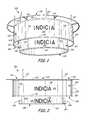
- FIG. 2illustrates a front view of the lighted signage structure of FIG. 1 .
- FIG. 3illustrates a back view of the lighted signage structure of FIG. 1 .
- FIG. 4illustrates a right side view of the lighted signage structure of FIG. 1 .
- FIG. 5illustrates a left side view of the lighted signage structure of FIG. 1 .
- FIG. 6illustrates a top view of the lighted signage structure of FIG. 1 .
- FIG. 7illustrates a bottom view of the lighted signage structure of FIG. 1 .
- FIG. 8illustrates a top perspective view of the lighted signage structure of FIG. 1 .
- FIG. 9is an enlarged detailed view of one of the bracket assemblies shown in FIGS. 1-8 and illustrated from an exterior side of a valance under one embodiment.
- FIG. 10is an enlarged detailed view of the bracket assembly shown in FIG. 9 and illustrated from an interior side of the valance.
- FIG. 11is a top perspective view of an arm of the bracket assembly illustrated in FIGS. 9 and 10 .
- FIG. 12is a top view of the arm of the bracket assembly illustrated in FIGS. 9-11 .
- FIG. 13is a side view of the arm of the bracket assembly illustrated in FIGS. 9-12 .
- FIG. 14illustrates a sectional view of the arm of the bracket assembly being inserted into an upper frame ring of a first drum of the lighted signage structure.
- FIG. 15illustrates an enlarged sectional view of a first end of the arm being inserted into the upper frame ring of the first drum of the light signage structure shown in FIG. 14 .
- FIG. 16is sectional view of the bracket assembly attaching a lighted valance to the first drum.
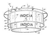
- FIGS. 1-8illustrate bottom perspective, front, back, right side, left side, top, bottom and top perspective views of a lighted signage structure 100 under one embodiment.
- Lighted signage structure 100includes a first drum or first barrel 102 and a second drum or second barrel 104 . While first and second drums 102 and 104 are illustrated as being circular in shape, in alternative embodiments other shapes are possible. For example, first and second drums 102 and 104 can be square or rectangular.
- first drum 102includes a first circular frame 106 supporting a first material 105 and second drum 104 includes a second circular frame 108 supporting a second material 107 .
- first material 105can be a plurality of first curved panels made of for example, styrene, while second material 107 can be fabric.
- Both first and second materials 105 and 107display indicia in the form of visual graphics and/or text.
- Both first and second circular frames 106 and 108include upper frame rings or upper frame channels 110 ( FIGS. 1-6 and 8 ) and 112 ( FIG. 8 ), lower frame rings or lower frame channels 114 ( FIGS. 1-5 and 7 - 8 ) and 116 ( FIGS.
- first drum or barrel 102is suspended from a ceiling by four first cable assemblies 122 . It should be realized, however, first drum or barrel 102 can be suspended from the ceiling by any number of first cable assemblies 122 . Under one embodiment, each of the four cable assemblies 122 directly attach to different points on the ceiling at first ends and directly attach to upper frame ring or channel 110 of first drum 102 at second ends. As illustrated in FIGS. 6-8 , first drum 102 also includes a pair of parallel cross bars 124 . Parallel cross bars 124 extend along chords rather than through the center of upper ring 110 . Second drum or barrel 104 is suspended from the parallel cross bars 124 of first drum 102 by four second cable assemblies 126 .
- second drum 104can be suspended from first drum 102 by any number of second cable assemblies 126 .
- Each of the four second cable assemblies 126directly attach to the different points on the cross bars 124 at first ends and directly attach to upper frame ring or channel 112 of the second drum 104 at second ends.
- upper frame ring 112 of second drum 104is located below upper frame ring 110 of first drum 102 , but not below lower frame ring 114 of first drum 102 . Therefore, second drum 104 appears to be nested within first drum 102 .
- first circular frame 106 of first drum 102supports a first material 105 having an outer circumferential surface 128 and second frame 108 of second drum 104 supports a second material 107 having an outer circumferential surface 130 .
- first material 105can comprise a plurality of panels, such as styrene panels, having outer surfaces and second material 107 can comprise fabric having an outer surface.
- outer surfaces 128 and 130include indicia 132 and 134 in the form of visual graphics and/or text.
- indicia 132 and 134can be printed or heat embossed onto outer surfaces 128 and 130 of first and second materials 105 and 107 .
- indicia 132 and 134are repeated about the outer surfaces 128 and 130 of first and second materials 105 and 107 .
- Lighted signage structure 100also includes a valance or crown 136 .
- Valance 136is coupled to upper frame ring or channel 110 of first drum 102 by a plurality of bracket or support assemblies 142 .
- Each bracket assembly 142connects valance 136 to upper frame ring 110 of first drum 102 such that valance 136 is located outwardly from outer surface 128 of first drum 102 .
- valance or crown 136is not attached directly to the ceiling or directly supported by the ceiling. Rather, as stated, valance 136 is coupled to and supported by first drum 102 via the plurality of bracket assemblies 142 .
- Valance 136in the embodiment illustrated in FIGS. 1-8 , includes a plurality of curved metal sections 137 and a plurality of spaced apart lights 138 .
- curved metal sections 137When curved metal sections 137 are positioned adjacent to each other, they form a circular hoop.
- valance or crown 136can be made of aluminum and include eight curved sections 137 having curved arcs of 45 degrees fitted adjacent to each other to form the continuous hoop. It should be realized that valance 136 can be made of any number of curved sections including a single curved section and may be made of different types of metallic material.
- sections 137can be straight sections if the drums 102 and 104 are of other types of shapes, for example square or rectangular.
- FIG. 9is an enlarged detailed view of bracket or support assembly 142 including valance 136 and upper frame ring 110 as illustrated from an exterior side of valance 136 under one embodiment.
- Bracket assembly 142includes a main body 148 having a first end 144 configured for attaching to upper frame ring or channel 110 and a second end 146 configured for attaching to valance or crown 136 .
- upper frame ring 110includes an upper channel 143 , a central channel and a lower channel.
- Upper channel 143includes a groove 145 that provides upper channel 143 with a top opening to receive first end 144 of main body 148 .
- the central channelis closed and, like upper channel 143 , the lower channel also includes a groove that provides the lower channel with a bottom opening to receive first material 105 of first drum 102 .
- Second end 146 of main body 148attaches to valance 136 at a location where two curved metal sections 137 are located adjacent to each other. At this location, each end of the adjacent curved metal sections include an aperture for receiving components of bracket assembly 142 such that valance 136 can be secured to main body 148 of bracket assembly 142 with a pair of fasteners 147 , such as hex nuts. It should be realized that bracket or support assemblies 142 can have a variety of different configurations than those exemplarily shown in FIG. 9 .
- FIG. 10is an enlarged detailed view of bracket assembly 142 including valance 136 and upper frame ring 110 as illustrated in FIG. 9 , but is illustrated from an interior side of valance 136 .
- each of the plurality of lights 138are mounted to spaced apart mounting plates 140 , which are fastened by, for example rivets 155 , to an interior side of curved metal sections 137 of valance or crown 136 at first legs 139 .
- Second legs 141 of mounting plates 140extend at an angle to the vertical interior sides of metal sections 137 such that second legs 141 protrude or extend inwardly from the interior side of each curved metal section 137 towards the outer surface 128 of first drum 102 .
- second legs 141 of mounting plates 140extend from the interior side of a curved metal section 137 such that second legs 141 are at 45 degree angle to the interior side of curved metal section 137 .
- the angle at which second legs 141 extendallow the outer surface 128 of first drum 102 to be substantially completely illuminated.
- each light 138is covered by a light dispersing element 135 , such as for example a lens 135 .
- Light scattering elements or light scattering lenses 135are of the type that are configured to diverge or disperse the light so that it better washes outer surface 128 of first drum 102 .
- a power cord 151 extending from one of the bracket assemblies 142 into the ceilingis connected to a power source.
- the power cord 151is located above the top side of the bracket assembly 142 and provides electrical wires 153 that run to and from the lights 138 .
- electrical wires 153supply power and electrically couple the lights around the interior side of valance 136 .
- each curved section 137includes twelve mounting plates 140 supporting twelve LED (light emitting diode) type lights 138 and corresponding lenses 135 that emit white light.
- each light 138is spaced a distance of approximately 5 inches.
- other distancesare possible and largely depend on the size of each curved section 137 .
- curved sections 137can include any number of mounting plates 140 and mounting plates 140 can include any of a variety of different number, type and color of lights 138 and different types of lenses.
- lights 138can be incandescent, fluorescent or the like.
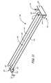
- FIGS. 11-13illustrate enlarged perspective, top and side views of the bracket or support assembly 142 illustrated in FIGS. 9 and 10 .
- bracket assembly 142includes main body 148 having first end 144 , second end 146 and an arm 149 extending between the first end 144 and the second end 146 .
- First end 144is configured for attaching to upper channel 142 of upper frame ring 110 through groove 145 while second end 146 is configured for attaching to valance or crown 136 .
- arm 149comprises a sheet metal that is bent along its longitudinal sides such that it has a substantially planar section 150 , a first side wing 152 and a second side wing 154 .
- the bent sidesprovide main body 148 with structural integrity.
- arm 149can have other configurations.
- the entire arm 149can be substantially planar.
- First end 144includes a recessed section 156 integrally formed with arm 149 and is substantially parallel with and recessed from substantially planar section 150 of arm 149 by a first height 157 .
- Recessed section 156includes an aperture 158 for receiving a fastener.
- First end 144also includes a first lip 160 integrally formed with recessed section 156 at its lateral edge so as to provide a substantially planar surface having a second height 161 that is less than first height 157 .
- the plane that first lip 160 occupiesis oriented substantially perpendicular to the plane recessed section 156 occupies and the plane substantially planar section 150 and first and second side wings 152 and 154 occupy.
- a gusset or plate 162is welded to arm 149 at substantially planar section 150 and to recessed section 156 for strengthening first end 144 .
- Second end 146includes a base section 164 integrally formed with arm 149 and substantially parallel with and in plane with substantially planar section 150 . Attached to base section 164 are a pair of threaded studs 166 . The pair of threaded studs 166 protrude upward from base section 164 and extend to a distal end 167 . The pair of threaded studs 166 are configured to be inserted through the apertures in curved metal sections 137 to secure second end 146 to valance or crown 136 . Second end 146 also includes a second lip 168 located on the lateral edge of base section 164 . Second lip 168 is integrally formed with base section 164 so as to provide a substantially planar surface having a third height 169 . The plane that second lip 168 occupies is oriented substantially perpendicular to the plane base section 164 and substantially planar section 150 and first and second side wings 152 and 154 occupy.
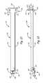
- FIG. 13illustrates a sectional view of first end 144 of bracket assembly 142 being assembled to upper frame ring 110 of first drum 102 .
- recessed section 156 and first lip 160are inserted through groove 145 by moving main body 148 in a direction 170 .
- FIG. 14illustrates an enlarged sectional view of second end 144 of bracket assembly 142 . After recessed section 156 and first lip 160 are inserted through groove 145 , recessed section 156 and first lip 160 are positioned within upper channel 143 by moving arm 149 in a direction 171 such that first lip 160 holds recessed section 156 within upper channel 143 .
- FIG. 15illustrates a sectional view of an assembled bracket or support assembly 142 .
- bracket assembly 142is attached to upper frame ring 110 of first drum 102 at first end 144 of arm 149 and attached to valance or crown 136 at second end 146 of arm 149 .
- a fastener 172such as a thumb screw, is threaded through aperture 158 in recessed section 156 so that it contacts the bottom of upper channel 143 to secure first end 144 into upper channel 143 of upper frame ring 110 . Also in FIG.
- second end 146 of bracket assembly 142is attached to valance or crown 136 by inserting studs 166 through the apertures in the curved metal sections 137 of valance 136 and then providing fasteners 147 to secure the threaded studs 166 to valance 136 .
- fasteners 147such as hex nuts, are received by studs 166 .
Landscapes
- Physics & Mathematics (AREA)
- General Physics & Mathematics (AREA)
- Engineering & Computer Science (AREA)
- Theoretical Computer Science (AREA)
- Illuminated Signs And Luminous Advertising (AREA)
Abstract
Description
Claims (20)
Priority Applications (1)
| Application Number | Priority Date | Filing Date | Title |
|---|---|---|---|
| US12/959,928US8256151B2 (en) | 2010-12-03 | 2010-12-03 | Lighted signage structure |
Applications Claiming Priority (1)
| Application Number | Priority Date | Filing Date | Title |
|---|---|---|---|
| US12/959,928US8256151B2 (en) | 2010-12-03 | 2010-12-03 | Lighted signage structure |
Publications (2)
| Publication Number | Publication Date |
|---|---|
| US20120137550A1 US20120137550A1 (en) | 2012-06-07 |
| US8256151B2true US8256151B2 (en) | 2012-09-04 |
Family
ID=46160867
Family Applications (1)
| Application Number | Title | Priority Date | Filing Date |
|---|---|---|---|
| US12/959,928Expired - Fee RelatedUS8256151B2 (en) | 2010-12-03 | 2010-12-03 | Lighted signage structure |
Country Status (1)
| Country | Link |
|---|---|
| US (1) | US8256151B2 (en) |
Cited By (22)
| Publication number | Priority date | Publication date | Assignee | Title |
|---|---|---|---|---|
| US20120257388A1 (en)* | 2011-04-11 | 2012-10-11 | Schonbek Worldwide Lighting Inc. | Light fixtures, methods of suspending a plurality of light sources, an ornament mounting, and a method for mounting an ornament |
| USD686363S1 (en)* | 2012-10-24 | 2013-07-16 | 3Form, Inc. | Rectilinear pendant light fixture |
| US20140268793A1 (en)* | 2013-03-12 | 2014-09-18 | Leo D. LaRose | Refrigerated display merchandiser with light filter |
| US20150362149A1 (en)* | 2010-11-01 | 2015-12-17 | Quarkstar Llc | Solid State Bidirectional Light Sheet Having Vertical Orientation |
| US20160363263A1 (en)* | 2015-02-11 | 2016-12-15 | Robert Stockham | System and method for movably mounting arena-type displays |
| US20160377245A1 (en)* | 2015-06-23 | 2016-12-29 | Axis Lighting Inc. | Supporting accessories for ceiling structures |
| US10107456B2 (en) | 2011-02-22 | 2018-10-23 | Quarkstar Llc | Solid state lamp using modular light emitting elements |
| US10288229B2 (en) | 2011-02-22 | 2019-05-14 | Quarkstar Llc | Solid state lamp using light emitting strips |
| USD859719S1 (en) | 2015-06-23 | 2019-09-10 | Axis Lighting Inc. | Luminaire |
| US10512343B1 (en)* | 2018-12-12 | 2019-12-24 | Run like the Wind, LLC | Ribbon medical display |
| USD878663S1 (en)* | 2017-06-07 | 2020-03-17 | Lg Electronics Inc. | Digital sign |
| USD916969S1 (en)* | 2018-07-09 | 2021-04-20 | Nanolumens Acquisition, Inc. | Ring shaped two-sided light emitting digital display |
| USD967898S1 (en)* | 2020-05-21 | 2022-10-25 | Aristocrat Technologies Australia Pty Limited | Gaming machine island |
| USD971337S1 (en) | 2019-10-04 | 2022-11-29 | Aristocrat Technologies Australia Pty Limited | Gaming machine island |
| USD985673S1 (en)* | 2018-11-14 | 2023-05-09 | Aristocrat Technologies Australia Pty Limited | Gaming machine display |
| US11701594B2 (en) | 2019-04-16 | 2023-07-18 | Aristocrat Technologies Australia Pty Limited | Overhead display having concentric inner and outer displays and associated systems and methods |
| USD1000180S1 (en)* | 2017-10-02 | 2023-10-03 | Thinking Ergonomix Pty Limited | Acoustic cone |
| USD1006886S1 (en) | 2021-04-23 | 2023-12-05 | Aristocrat Technologies Australia Pty Limited | Gaming machine island |
| USD1020904S1 (en) | 2021-05-10 | 2024-04-02 | Aristocrat Technologies Australia Pty Limited | Wedge for a gaming machine island |
| USD1044955S1 (en) | 2020-09-11 | 2024-10-01 | Aristocrat Technologies, Inc. | Display screen device |
| USD1075931S1 (en)* | 2023-03-16 | 2025-05-20 | Aristocrat Technologies, Inc. | Gaming machine |
| USD1075932S1 (en)* | 2023-03-16 | 2025-05-20 | Aristocrat Technologies, Inc. | Gaming machine |
Families Citing this family (11)
| Publication number | Priority date | Publication date | Assignee | Title |
|---|---|---|---|---|
| WO2019214853A1 (en)* | 2018-05-07 | 2019-11-14 | Eaton Intelligent Power Limited | Suspended pendant lightguide luminaire with sound dampening |
| US10235910B1 (en)* | 2018-07-10 | 2019-03-19 | International Paper Company | Split signage assembly |
| USD931369S1 (en)* | 2018-07-17 | 2021-09-21 | International Paper Company | Signage system |
| USD892384S1 (en)* | 2018-11-07 | 2020-08-04 | Williams-Sonoma, Inc. | Lamp |
| USD899667S1 (en)* | 2019-05-17 | 2020-10-20 | Signify Holding B.V. | Suspended cylindrical luminaire with sound dampening |
| USD899668S1 (en)* | 2019-05-17 | 2020-10-20 | Signify Holding B.V. | Suspended pyramidal luminaire with sound dampening |
| US11990062B2 (en)* | 2021-12-11 | 2024-05-21 | Wertz Werkz, LLC | Collapsible display apparatus |
| USD1007044S1 (en)* | 2023-08-22 | 2023-12-05 | Xiaoyan LUO | Ceiling light cage |
| USD1050563S1 (en)* | 2024-05-09 | 2024-11-05 | Xiaoyan LUO | Lamp shade |
| USD1061860S1 (en)* | 2024-10-21 | 2025-02-11 | Wanqi Lun | Ceiling fan shade |
| USD1094816S1 (en)* | 2025-03-13 | 2025-09-23 | Guangzhou Maodeng Trading Co., Ltd. | Ceiling fan with light |
Citations (71)
| Publication number | Priority date | Publication date | Assignee | Title |
|---|---|---|---|---|
| US1354262A (en) | 1919-06-28 | 1920-09-28 | Frederick W Mathieu | Globe for lighting-fixtures |
| US2195154A (en) | 1939-05-08 | 1940-03-26 | Wm M Kahanowitz | Electric light fixture |
| US2517963A (en) | 1946-01-22 | 1950-08-08 | Marcus S Bausch | Vegetable display rack |
| US2608777A (en) | 1949-07-30 | 1952-09-02 | Youngstown Mfg Inc | Price tag and molding trim |
| US2830395A (en)* | 1957-03-19 | 1958-04-15 | Howard T Hutchens | Carousel sign |
| US3201881A (en) | 1963-05-06 | 1965-08-24 | Dechar Corp | Advertising devices |
| US3340633A (en)* | 1965-03-22 | 1967-09-12 | Southern Spring Bed Company | Moving display |
| US3759398A (en) | 1970-03-02 | 1973-09-18 | R Romney | Fabric display and merchandising system |
| US3854591A (en) | 1973-04-26 | 1974-12-17 | R Schuessler | Disposable hanger retainer for display racks |
| US3984931A (en) | 1975-08-28 | 1976-10-12 | Belokin Jr Paul | Illuminated overhead advertising display |
| US4001959A (en) | 1975-07-23 | 1977-01-11 | Grendahl Russell S | Rotary picture frame |
| US4064427A (en)* | 1975-08-12 | 1977-12-20 | Hansen Mfg. Co. Of Florida, Inc. | Safety guard and light fixture attachment for ceiling fans |
| US4091706A (en) | 1976-10-06 | 1978-05-30 | Ludwig Industries | Construction of illuminated drums |
| US4441282A (en) | 1981-04-24 | 1984-04-10 | Hunter Douglas International N.V. Rooi Catootje | Suspended ceiling |
| US4446973A (en) | 1981-09-02 | 1984-05-08 | Fuller Robert T | Display system for stiff flat samples |
| US4454671A (en) | 1982-07-07 | 1984-06-19 | Trans-Ad Corporation | Timetable display |
| USD281790S (en) | 1983-11-17 | 1985-12-17 | Dualite, Inc. | Illuminated hanging sign cabinet |
| US4747025A (en) | 1986-09-30 | 1988-05-24 | Barton Daniel W | Low voltage lighting fixture with track electrodes |
| US4776121A (en) | 1987-04-27 | 1988-10-11 | Vicino Robert K | Inflatable sign |
| US4849864A (en) | 1987-09-29 | 1989-07-18 | Louis Forrest | Adjustable lighting assembly |
| US4856216A (en) | 1986-05-19 | 1989-08-15 | Gross Jan S | Advertising cover for fluorescent lighting |
| US4896779A (en) | 1987-08-14 | 1990-01-30 | L'oreal, S.A. | Display shelf organizer |
| USD306352S (en) | 1987-01-07 | 1990-02-27 | Glassman Fredrick R | Light fixture |
| US4994943A (en) | 1990-05-14 | 1991-02-19 | Aspenwall John E | Cantilevered lighting system |
| US5057981A (en) | 1990-07-16 | 1991-10-15 | Bowen Richard D | Decorative lighted configurations |
| US5062534A (en) | 1990-03-28 | 1991-11-05 | Burlington Industries, Inc. | Fabric sample display |
| WO1991019934A1 (en)* | 1990-06-18 | 1991-12-26 | A. Schonbek & Co., Inc. | Precision chandelier frame |
| US5282331A (en) | 1992-06-19 | 1994-02-01 | M & M Displays, Inc. | Display module |
| USD350568S (en) | 1993-10-18 | 1994-09-13 | Lacarelli Designs and Displays, Inc. | Retractable information display unit |
| US5528469A (en) | 1994-09-07 | 1996-06-18 | Todd, Jr.; Alvin E. | Light assembly for a ceiling fan |
| US5575098A (en) | 1993-04-19 | 1996-11-19 | Sunbeam Oster | Illuminated display apparatus |
| US5617661A (en) | 1995-09-14 | 1997-04-08 | Ndr Corporation | Flexible sign board for blade signs |
| US5647485A (en) | 1996-01-19 | 1997-07-15 | L'oreal S.A. | Display system for hair swatches |
| US5649379A (en)* | 1995-07-11 | 1997-07-22 | Rose Displays | Suspended multi-sided message display signs |
| US5703564A (en)* | 1995-11-21 | 1997-12-30 | Klever-Kart, Inc. | Mobile advertising device with electronic transmission capabilities |
| US5924367A (en) | 1997-04-10 | 1999-07-20 | Rtc Industries, Inc. | Shelf sign system |
| US5992072A (en) | 1995-06-05 | 1999-11-30 | Garfinkle; Benjamin L. | Shelf extender |
| US6082687A (en) | 1998-05-13 | 2000-07-04 | Fasteners For Retail, Inc. | Flag holder and label holder |
| US6193384B1 (en) | 1998-03-18 | 2001-02-27 | Buckminster G. Stein | Ceiling fan sign |
| US6233102B1 (en) | 2000-03-21 | 2001-05-15 | Veigh E. Hogan, Jr. | Point-of-purchase display |
| US6269570B1 (en) | 1999-07-27 | 2001-08-07 | Colleen Miles | Signage structure |
| US6321475B1 (en) | 2000-06-13 | 2001-11-27 | Natural Science Industries, Ltd. | Shelf-mounted display device |
| US6341441B1 (en) | 1999-12-28 | 2002-01-29 | Eduardo Morales | Illuminated address sign |
| US6341755B1 (en) | 1998-04-02 | 2002-01-29 | Fasteners For Retail, Inc. | Shelf top adapter |
| US6349863B1 (en) | 2001-02-01 | 2002-02-26 | Betty F. Frye | Garment display assembly |
| USD456550S1 (en) | 2000-06-05 | 2002-04-30 | Boyd Lighting Company | Pendant lamp with tubular shade of olive-shaped cross section |
| USD457364S1 (en) | 2001-04-27 | 2002-05-21 | Thomas M. Shea | Adjustable merchandise shelf extender |
| US6467209B1 (en) | 1999-11-17 | 2002-10-22 | Thomas M. Vickers | Overhead media display system |
| US6634125B2 (en) | 2001-02-22 | 2003-10-21 | Brian Abramson | Information display system |
| US6644606B1 (en) | 2000-06-29 | 2003-11-11 | Gregg A. Seidel | Mounting support bracket for an advertising windup reel |
| USD488837S1 (en) | 2003-02-12 | 2004-04-20 | Lami Products, Inc. | Display placard |
| USD489472S1 (en) | 2001-06-15 | 2004-05-04 | Herman Miller Inc. | Light fixture |
| US6786621B2 (en) | 2000-08-31 | 2004-09-07 | Mode Interiors Llc | Do-it-yourself lampshade kit |
| US6827465B2 (en) | 2000-02-09 | 2004-12-07 | Sylvan R. Shemitz Designs, Inc. | Display lighting system with uplight |
| US20060165529A1 (en) | 2005-01-12 | 2006-07-27 | Sobel Martin M | Air circulation system-driven, suspended rotating display device |
| WO2007018962A2 (en) | 2005-08-03 | 2007-02-15 | Gift Technologies, Lp | Composite poles and methods for forming the same |
| US7293895B2 (en) | 2005-10-20 | 2007-11-13 | Cathode Lighting Systems, Inc. | Modular lighting system and method of installation |
| USD561928S1 (en) | 2006-10-11 | 2008-02-12 | Beta-Calco Inc. | Light fixture |
| US20080093317A1 (en) | 2006-10-20 | 2008-04-24 | Joalpe Industria De Expositores, S.A. | Display of tagging item such as an advertising leaflet or the like on a shelf of a selling surface |
| US7377061B2 (en) | 2004-10-04 | 2008-05-27 | Target Brands, Inc. | Light box display |
| US20080130297A1 (en) | 2006-12-04 | 2008-06-05 | Mastercraft International Usa, Inc. | Modular lamp shade |
| USD571948S1 (en) | 2007-12-26 | 2008-06-24 | Seed Lighting Design Co., Ltd. | Lampshade |
| USD580585S1 (en) | 2007-09-21 | 2008-11-11 | Boyd Lighting Fixture Company | Lighting fixture |
| US20080282592A1 (en) | 2007-05-15 | 2008-11-20 | Southern Imperial, Inc. | Roll Formed Channel For Electronic Price Label Units |
| USD585584S1 (en) | 2008-01-31 | 2009-01-27 | Eglo Leuchten Gmbh | Light fixture |
| USD595891S1 (en) | 2008-10-08 | 2009-07-07 | Eglo Leuchten Gmbh | Light fixture |
| USD596337S1 (en) | 2008-11-25 | 2009-07-14 | Eglo Leuchten Gmbh | Light fixture |
| US7610704B1 (en)* | 2006-12-27 | 2009-11-03 | Nowicki Michael J | Display structure with moving attraction elements |
| US7631982B1 (en) | 2007-08-09 | 2009-12-15 | Mr. Go Green, Inc. | Light attachment system |
| USD614704S1 (en) | 2009-08-20 | 2010-04-27 | Target Brands, Inc. | Display signage |
| USD622436S1 (en) | 2010-03-16 | 2010-08-24 | Target Brands, Inc. | Lighting fixture |
- 2010
- 2010-12-03USUS12/959,928patent/US8256151B2/ennot_activeExpired - Fee Related
Patent Citations (72)
| Publication number | Priority date | Publication date | Assignee | Title |
|---|---|---|---|---|
| US1354262A (en) | 1919-06-28 | 1920-09-28 | Frederick W Mathieu | Globe for lighting-fixtures |
| US2195154A (en) | 1939-05-08 | 1940-03-26 | Wm M Kahanowitz | Electric light fixture |
| US2517963A (en) | 1946-01-22 | 1950-08-08 | Marcus S Bausch | Vegetable display rack |
| US2608777A (en) | 1949-07-30 | 1952-09-02 | Youngstown Mfg Inc | Price tag and molding trim |
| US2830395A (en)* | 1957-03-19 | 1958-04-15 | Howard T Hutchens | Carousel sign |
| US3201881A (en) | 1963-05-06 | 1965-08-24 | Dechar Corp | Advertising devices |
| US3340633A (en)* | 1965-03-22 | 1967-09-12 | Southern Spring Bed Company | Moving display |
| US3759398A (en) | 1970-03-02 | 1973-09-18 | R Romney | Fabric display and merchandising system |
| US3854591A (en) | 1973-04-26 | 1974-12-17 | R Schuessler | Disposable hanger retainer for display racks |
| US4001959A (en) | 1975-07-23 | 1977-01-11 | Grendahl Russell S | Rotary picture frame |
| US4064427A (en)* | 1975-08-12 | 1977-12-20 | Hansen Mfg. Co. Of Florida, Inc. | Safety guard and light fixture attachment for ceiling fans |
| US3984931A (en) | 1975-08-28 | 1976-10-12 | Belokin Jr Paul | Illuminated overhead advertising display |
| US4091706A (en) | 1976-10-06 | 1978-05-30 | Ludwig Industries | Construction of illuminated drums |
| US4441282A (en) | 1981-04-24 | 1984-04-10 | Hunter Douglas International N.V. Rooi Catootje | Suspended ceiling |
| US4446973A (en) | 1981-09-02 | 1984-05-08 | Fuller Robert T | Display system for stiff flat samples |
| US4454671A (en) | 1982-07-07 | 1984-06-19 | Trans-Ad Corporation | Timetable display |
| USD281790S (en) | 1983-11-17 | 1985-12-17 | Dualite, Inc. | Illuminated hanging sign cabinet |
| US4856216A (en) | 1986-05-19 | 1989-08-15 | Gross Jan S | Advertising cover for fluorescent lighting |
| US4747025A (en) | 1986-09-30 | 1988-05-24 | Barton Daniel W | Low voltage lighting fixture with track electrodes |
| USD306352S (en) | 1987-01-07 | 1990-02-27 | Glassman Fredrick R | Light fixture |
| US4776121A (en) | 1987-04-27 | 1988-10-11 | Vicino Robert K | Inflatable sign |
| US4896779A (en) | 1987-08-14 | 1990-01-30 | L'oreal, S.A. | Display shelf organizer |
| US4849864A (en) | 1987-09-29 | 1989-07-18 | Louis Forrest | Adjustable lighting assembly |
| US5062534A (en) | 1990-03-28 | 1991-11-05 | Burlington Industries, Inc. | Fabric sample display |
| US4994943A (en) | 1990-05-14 | 1991-02-19 | Aspenwall John E | Cantilevered lighting system |
| WO1991019934A1 (en)* | 1990-06-18 | 1991-12-26 | A. Schonbek & Co., Inc. | Precision chandelier frame |
| US5057981A (en) | 1990-07-16 | 1991-10-15 | Bowen Richard D | Decorative lighted configurations |
| US5282331A (en) | 1992-06-19 | 1994-02-01 | M & M Displays, Inc. | Display module |
| US5575098A (en) | 1993-04-19 | 1996-11-19 | Sunbeam Oster | Illuminated display apparatus |
| USD350568S (en) | 1993-10-18 | 1994-09-13 | Lacarelli Designs and Displays, Inc. | Retractable information display unit |
| US5528469A (en) | 1994-09-07 | 1996-06-18 | Todd, Jr.; Alvin E. | Light assembly for a ceiling fan |
| US5992072A (en) | 1995-06-05 | 1999-11-30 | Garfinkle; Benjamin L. | Shelf extender |
| US5649379A (en)* | 1995-07-11 | 1997-07-22 | Rose Displays | Suspended multi-sided message display signs |
| US5832644A (en) | 1995-09-14 | 1998-11-10 | Ndr Corporation | Flexible sign board for blade signs |
| US5617661A (en) | 1995-09-14 | 1997-04-08 | Ndr Corporation | Flexible sign board for blade signs |
| US5703564A (en)* | 1995-11-21 | 1997-12-30 | Klever-Kart, Inc. | Mobile advertising device with electronic transmission capabilities |
| US5647485A (en) | 1996-01-19 | 1997-07-15 | L'oreal S.A. | Display system for hair swatches |
| US5924367A (en) | 1997-04-10 | 1999-07-20 | Rtc Industries, Inc. | Shelf sign system |
| US6193384B1 (en) | 1998-03-18 | 2001-02-27 | Buckminster G. Stein | Ceiling fan sign |
| US6341755B1 (en) | 1998-04-02 | 2002-01-29 | Fasteners For Retail, Inc. | Shelf top adapter |
| US6082687A (en) | 1998-05-13 | 2000-07-04 | Fasteners For Retail, Inc. | Flag holder and label holder |
| US6269570B1 (en) | 1999-07-27 | 2001-08-07 | Colleen Miles | Signage structure |
| US6467209B1 (en) | 1999-11-17 | 2002-10-22 | Thomas M. Vickers | Overhead media display system |
| US6341441B1 (en) | 1999-12-28 | 2002-01-29 | Eduardo Morales | Illuminated address sign |
| US6827465B2 (en) | 2000-02-09 | 2004-12-07 | Sylvan R. Shemitz Designs, Inc. | Display lighting system with uplight |
| US6233102B1 (en) | 2000-03-21 | 2001-05-15 | Veigh E. Hogan, Jr. | Point-of-purchase display |
| USD456550S1 (en) | 2000-06-05 | 2002-04-30 | Boyd Lighting Company | Pendant lamp with tubular shade of olive-shaped cross section |
| US6321475B1 (en) | 2000-06-13 | 2001-11-27 | Natural Science Industries, Ltd. | Shelf-mounted display device |
| US6644606B1 (en) | 2000-06-29 | 2003-11-11 | Gregg A. Seidel | Mounting support bracket for an advertising windup reel |
| US6786621B2 (en) | 2000-08-31 | 2004-09-07 | Mode Interiors Llc | Do-it-yourself lampshade kit |
| US6349863B1 (en) | 2001-02-01 | 2002-02-26 | Betty F. Frye | Garment display assembly |
| US6634125B2 (en) | 2001-02-22 | 2003-10-21 | Brian Abramson | Information display system |
| USD457364S1 (en) | 2001-04-27 | 2002-05-21 | Thomas M. Shea | Adjustable merchandise shelf extender |
| USD489472S1 (en) | 2001-06-15 | 2004-05-04 | Herman Miller Inc. | Light fixture |
| USD488837S1 (en) | 2003-02-12 | 2004-04-20 | Lami Products, Inc. | Display placard |
| US7377061B2 (en) | 2004-10-04 | 2008-05-27 | Target Brands, Inc. | Light box display |
| US20060165529A1 (en) | 2005-01-12 | 2006-07-27 | Sobel Martin M | Air circulation system-driven, suspended rotating display device |
| WO2007018962A2 (en) | 2005-08-03 | 2007-02-15 | Gift Technologies, Lp | Composite poles and methods for forming the same |
| US7293895B2 (en) | 2005-10-20 | 2007-11-13 | Cathode Lighting Systems, Inc. | Modular lighting system and method of installation |
| USD561928S1 (en) | 2006-10-11 | 2008-02-12 | Beta-Calco Inc. | Light fixture |
| US20080093317A1 (en) | 2006-10-20 | 2008-04-24 | Joalpe Industria De Expositores, S.A. | Display of tagging item such as an advertising leaflet or the like on a shelf of a selling surface |
| US20080130297A1 (en) | 2006-12-04 | 2008-06-05 | Mastercraft International Usa, Inc. | Modular lamp shade |
| US7610704B1 (en)* | 2006-12-27 | 2009-11-03 | Nowicki Michael J | Display structure with moving attraction elements |
| US20080282592A1 (en) | 2007-05-15 | 2008-11-20 | Southern Imperial, Inc. | Roll Formed Channel For Electronic Price Label Units |
| US7631982B1 (en) | 2007-08-09 | 2009-12-15 | Mr. Go Green, Inc. | Light attachment system |
| USD580585S1 (en) | 2007-09-21 | 2008-11-11 | Boyd Lighting Fixture Company | Lighting fixture |
| USD571948S1 (en) | 2007-12-26 | 2008-06-24 | Seed Lighting Design Co., Ltd. | Lampshade |
| USD585584S1 (en) | 2008-01-31 | 2009-01-27 | Eglo Leuchten Gmbh | Light fixture |
| USD595891S1 (en) | 2008-10-08 | 2009-07-07 | Eglo Leuchten Gmbh | Light fixture |
| USD596337S1 (en) | 2008-11-25 | 2009-07-14 | Eglo Leuchten Gmbh | Light fixture |
| USD614704S1 (en) | 2009-08-20 | 2010-04-27 | Target Brands, Inc. | Display signage |
| USD622436S1 (en) | 2010-03-16 | 2010-08-24 | Target Brands, Inc. | Lighting fixture |
Non-Patent Citations (1)
| Title |
|---|
| Moss Inc, "Retail Catalog," pp. 1-24, http://www.mossinc.com/downloads/Retail%20Catalog.pdf (last visited Oct. 7, 2010). |
Cited By (50)
| Publication number | Priority date | Publication date | Assignee | Title |
|---|---|---|---|---|
| US20150362149A1 (en)* | 2010-11-01 | 2015-12-17 | Quarkstar Llc | Solid State Bidirectional Light Sheet Having Vertical Orientation |
| US10132466B2 (en)* | 2010-11-01 | 2018-11-20 | Quarkstar Llc | Bidirectional light emitting diode light sheet |
| US10859213B2 (en) | 2011-02-22 | 2020-12-08 | Quarkstar Llc | Solid state lamp using light emitting strips |
| US11359772B2 (en) | 2011-02-22 | 2022-06-14 | Quarkstar Llc | Solid state lamp using light emitting strips |
| US11333305B2 (en) | 2011-02-22 | 2022-05-17 | Quarkstar Llc | Solid state lamp using light emitting strips |
| US11098855B2 (en) | 2011-02-22 | 2021-08-24 | Quarkstar Llc | Solid state lamp using light emitting strips |
| US12259096B2 (en) | 2011-02-22 | 2025-03-25 | Quarkstar Llc | Solid state lamp using light emitting strips |
| US11060672B1 (en) | 2011-02-22 | 2021-07-13 | Quarkstar Llc | Solid state lamp using light emitting strips |
| US10107456B2 (en) | 2011-02-22 | 2018-10-23 | Quarkstar Llc | Solid state lamp using modular light emitting elements |
| US10634288B2 (en) | 2011-02-22 | 2020-04-28 | Quarkstar Llc | Solid state lamp using light emitting strips |
| US11920739B2 (en) | 2011-02-22 | 2024-03-05 | Quarkstar Llc | Solid state lamp using light emitting strips |
| US10288229B2 (en) | 2011-02-22 | 2019-05-14 | Quarkstar Llc | Solid state lamp using light emitting strips |
| US11009191B1 (en) | 2011-02-22 | 2021-05-18 | Quarkstar Llc | Solid state lamp using light emitting strips |
| US11821590B2 (en) | 2011-02-22 | 2023-11-21 | Quarkstar Llc | Solid state lamp using light emitting strips |
| US10634287B2 (en) | 2011-02-22 | 2020-04-28 | Quarkstar Llc | Solid state lamp using light emitting strips |
| US11015766B1 (en) | 2011-02-22 | 2021-05-25 | Quarkstar Llc | Solid state lamp using light emitting strips |
| US11603967B2 (en) | 2011-02-22 | 2023-03-14 | Quarkstar Llc | Solid state lamp using light emitting strips |
| US10690294B2 (en) | 2011-02-22 | 2020-06-23 | Quarkstar Llc | Solid state lamp using light emitting strips |
| US11339928B2 (en) | 2011-02-22 | 2022-05-24 | Quarkstar Llc | Solid state lamp using light emitting strips |
| US11598491B2 (en) | 2011-02-22 | 2023-03-07 | Quarkstar Llc | Solid state lamp using light emitting strips |
| US10962177B2 (en) | 2011-02-22 | 2021-03-30 | Quarkstar Llc | Solid state lamp using light emitting strips |
| US20120257388A1 (en)* | 2011-04-11 | 2012-10-11 | Schonbek Worldwide Lighting Inc. | Light fixtures, methods of suspending a plurality of light sources, an ornament mounting, and a method for mounting an ornament |
| US8714775B2 (en)* | 2011-04-11 | 2014-05-06 | Swarovski Lighting, Ltd. | Light fixtures, methods of suspending a plurality of light sources, an ornament mounting, and a method for mounting an ornament |
| USD686363S1 (en)* | 2012-10-24 | 2013-07-16 | 3Form, Inc. | Rectilinear pendant light fixture |
| US20140268793A1 (en)* | 2013-03-12 | 2014-09-18 | Leo D. LaRose | Refrigerated display merchandiser with light filter |
| US9696009B2 (en)* | 2013-03-12 | 2017-07-04 | Leo D. LaRose | Refrigerated display merchandiser with light filter |
| US20160363263A1 (en)* | 2015-02-11 | 2016-12-15 | Robert Stockham | System and method for movably mounting arena-type displays |
| USD859719S1 (en) | 2015-06-23 | 2019-09-10 | Axis Lighting Inc. | Luminaire |
| US20160377245A1 (en)* | 2015-06-23 | 2016-12-29 | Axis Lighting Inc. | Supporting accessories for ceiling structures |
| US10288238B2 (en)* | 2015-06-23 | 2019-05-14 | Axis Lighting Inc. | Supporting accessories for ceiling structures |
| US10871263B2 (en) | 2015-06-23 | 2020-12-22 | Axis Lighting Inc. | Supporting accessories for ceiling structures |
| USD878663S1 (en)* | 2017-06-07 | 2020-03-17 | Lg Electronics Inc. | Digital sign |
| USD1000180S1 (en)* | 2017-10-02 | 2023-10-03 | Thinking Ergonomix Pty Limited | Acoustic cone |
| USD916969S1 (en)* | 2018-07-09 | 2021-04-20 | Nanolumens Acquisition, Inc. | Ring shaped two-sided light emitting digital display |
| USD985673S1 (en)* | 2018-11-14 | 2023-05-09 | Aristocrat Technologies Australia Pty Limited | Gaming machine display |
| US10512343B1 (en)* | 2018-12-12 | 2019-12-24 | Run like the Wind, LLC | Ribbon medical display |
| US11701594B2 (en) | 2019-04-16 | 2023-07-18 | Aristocrat Technologies Australia Pty Limited | Overhead display having concentric inner and outer displays and associated systems and methods |
| USD1079817S1 (en) | 2019-10-04 | 2025-06-17 | Aristocrat Technologies Australia Pty Limited | Gaming machine island |
| USD971337S1 (en) | 2019-10-04 | 2022-11-29 | Aristocrat Technologies Australia Pty Limited | Gaming machine island |
| USD1070994S1 (en) | 2019-10-04 | 2025-04-15 | Aristocrat Technologies Australia Pty Limited | Gaming machine island |
| USD995643S1 (en) | 2019-10-04 | 2023-08-15 | Aristocrat Technologies Australia Pty Limited | Gaming machine island |
| USD1067980S1 (en) | 2020-05-21 | 2025-03-25 | Aristocrat Technologies Australia Pty Limited | Gaming machine island |
| USD1002729S1 (en) | 2020-05-21 | 2023-10-24 | Aristocrat Technologies Australia Pty Limited | Gaming machine island |
| USD967898S1 (en)* | 2020-05-21 | 2022-10-25 | Aristocrat Technologies Australia Pty Limited | Gaming machine island |
| USD1044955S1 (en) | 2020-09-11 | 2024-10-01 | Aristocrat Technologies, Inc. | Display screen device |
| USD1046976S1 (en) | 2021-04-23 | 2024-10-15 | Aristocrat Technologies Australia Pty Limited | Gaming machine island |
| USD1006886S1 (en) | 2021-04-23 | 2023-12-05 | Aristocrat Technologies Australia Pty Limited | Gaming machine island |
| USD1020904S1 (en) | 2021-05-10 | 2024-04-02 | Aristocrat Technologies Australia Pty Limited | Wedge for a gaming machine island |
| USD1075931S1 (en)* | 2023-03-16 | 2025-05-20 | Aristocrat Technologies, Inc. | Gaming machine |
| USD1075932S1 (en)* | 2023-03-16 | 2025-05-20 | Aristocrat Technologies, Inc. | Gaming machine |
Also Published As
| Publication number | Publication date |
|---|---|
| US20120137550A1 (en) | 2012-06-07 |
Similar Documents
| Publication | Publication Date | Title |
|---|---|---|
| US8256151B2 (en) | Lighted signage structure | |
| US20080049447A1 (en) | Edge lighted display system having multiple display faces | |
| WO2017078683A1 (en) | Illumination assembly providing backlight and downlight | |
| US6557282B1 (en) | Portable illuminated outdoor advertising display | |
| US20060191179A1 (en) | Compact road sign display | |
| KR200457486Y1 (en) | Mobile advertising vehicle with removable advertising panel | |
| KR100997744B1 (en) | Prefab Signboard for Advertising | |
| KR200444709Y1 (en) | Sign board structure for character attachment | |
| WO2016060484A1 (en) | Advertising banner holder | |
| KR101418251B1 (en) | Advertising frame mounting characters | |
| KR100876576B1 (en) | Signboard Attachment | |
| JP2012517713A (en) | LED assembly with improved visibility and form, method of attaching the same, and banner using the same | |
| KR101454744B1 (en) | The signage for advertising with excellent legibility | |
| JP4783806B2 (en) | Backlight mechanism and light emitting device having backlight mechanism | |
| KR101488895B1 (en) | Illumination advertisement sign board | |
| KR101243870B1 (en) | A sign device for showing road information | |
| JP3239591U (en) | utility pole advertising device | |
| KR101703120B1 (en) | Lighting devices | |
| KR20150017643A (en) | Coupling type illumination module having LED and illumination device having the same | |
| PL224659B1 (en) | Strip lighting | |
| FI115492B (en) | light Advertising | |
| KR200468066Y1 (en) | Turning signal lamp for signboard which is capable of change of LED light easily | |
| KR20150066040A (en) | visibility is excellent advertising | |
| KR200446353Y1 (en) | Sign board structure for character attachment | |
| KR200462221Y1 (en) | Lighting devive for signboard |
Legal Events
| Date | Code | Title | Description |
|---|---|---|---|
| AS | Assignment | Owner name:TARGET BRANDS, INC., MINNESOTA Free format text:ASSIGNMENT OF ASSIGNORS INTEREST;ASSIGNORS:STAFFORD, WILLIAM Y.;PENKIVECH, CHERYL J.;REEL/FRAME:025450/0087 Effective date:20101202 Owner name:TRINITY, LLC, NEW JERSEY Free format text:ASSIGNMENT OF ASSIGNORS INTEREST;ASSIGNORS:FARINOLA, JOHN P.;BABBONI, CHARLES J.;SOSNIAK, KRZYSZTOF;REEL/FRAME:025450/0238 Effective date:20101123 Owner name:TARGET BRANDS, INC., MINNESOTA Free format text:ASSIGNMENT OF ASSIGNORS INTEREST;ASSIGNOR:TRINITY, LLC;REEL/FRAME:025450/0298 Effective date:20101123 | |
| STCF | Information on status: patent grant | Free format text:PATENTED CASE | |
| FPAY | Fee payment | Year of fee payment:4 | |
| FEPP | Fee payment procedure | Free format text:MAINTENANCE FEE REMINDER MAILED (ORIGINAL EVENT CODE: REM.); ENTITY STATUS OF PATENT OWNER: LARGE ENTITY | |
| LAPS | Lapse for failure to pay maintenance fees | Free format text:PATENT EXPIRED FOR FAILURE TO PAY MAINTENANCE FEES (ORIGINAL EVENT CODE: EXP.); ENTITY STATUS OF PATENT OWNER: LARGE ENTITY | |
| STCH | Information on status: patent discontinuation | Free format text:PATENT EXPIRED DUE TO NONPAYMENT OF MAINTENANCE FEES UNDER 37 CFR 1.362 | |
| FP | Lapsed due to failure to pay maintenance fee | Effective date:20200904 |