US8255092B2 - Autonomous behaviors for a remote vehicle - Google Patents
Autonomous behaviors for a remote vehicleDownload PDFInfo
- Publication number
- US8255092B2 US8255092B2US12/102,838US10283808AUS8255092B2US 8255092 B2US8255092 B2US 8255092B2US 10283808 AUS10283808 AUS 10283808AUS 8255092 B2US8255092 B2US 8255092B2
- Authority
- US
- United States
- Prior art keywords
- behavior
- robot
- remote vehicle
- waypoints
- control
- Prior art date
- Legal status (The legal status is an assumption and is not a legal conclusion. Google has not performed a legal analysis and makes no representation as to the accuracy of the status listed.)
- Active, expires
Links
Images


Classifications
- G—PHYSICS
- G05—CONTROLLING; REGULATING
- G05D—SYSTEMS FOR CONTROLLING OR REGULATING NON-ELECTRIC VARIABLES
- G05D1/00—Control of position, course, altitude or attitude of land, water, air or space vehicles, e.g. using automatic pilots
- G05D1/60—Intended control result
- G05D1/617—Safety or protection, e.g. defining protection zones around obstacles or avoiding hazards
- G05D1/639—Resolving or avoiding being stuck or obstructed
- G—PHYSICS
- G05—CONTROLLING; REGULATING
- G05D—SYSTEMS FOR CONTROLLING OR REGULATING NON-ELECTRIC VARIABLES
- G05D1/00—Control of position, course, altitude or attitude of land, water, air or space vehicles, e.g. using automatic pilots
- G05D1/0088—Control of position, course, altitude or attitude of land, water, air or space vehicles, e.g. using automatic pilots characterized by the autonomous decision making process, e.g. artificial intelligence, predefined behaviours
- G—PHYSICS
- G05—CONTROLLING; REGULATING
- G05D—SYSTEMS FOR CONTROLLING OR REGULATING NON-ELECTRIC VARIABLES
- G05D1/00—Control of position, course, altitude or attitude of land, water, air or space vehicles, e.g. using automatic pilots
- G05D1/02—Control of position or course in two dimensions
- G05D1/021—Control of position or course in two dimensions specially adapted to land vehicles
- G05D1/0231—Control of position or course in two dimensions specially adapted to land vehicles using optical position detecting means
- G05D1/0246—Control of position or course in two dimensions specially adapted to land vehicles using optical position detecting means using a video camera in combination with image processing means
- G05D1/0251—Control of position or course in two dimensions specially adapted to land vehicles using optical position detecting means using a video camera in combination with image processing means extracting 3D information from a plurality of images taken from different locations, e.g. stereo vision
- G—PHYSICS
- G05—CONTROLLING; REGULATING
- G05D—SYSTEMS FOR CONTROLLING OR REGULATING NON-ELECTRIC VARIABLES
- G05D1/00—Control of position, course, altitude or attitude of land, water, air or space vehicles, e.g. using automatic pilots
- G05D1/02—Control of position or course in two dimensions
- G05D1/021—Control of position or course in two dimensions specially adapted to land vehicles
- G05D1/0276—Control of position or course in two dimensions specially adapted to land vehicles using signals provided by a source external to the vehicle
- G05D1/0278—Control of position or course in two dimensions specially adapted to land vehicles using signals provided by a source external to the vehicle using satellite positioning signals, e.g. GPS
- G—PHYSICS
- G06—COMPUTING OR CALCULATING; COUNTING
- G06F—ELECTRIC DIGITAL DATA PROCESSING
- G06F9/00—Arrangements for program control, e.g. control units
- G06F9/06—Arrangements for program control, e.g. control units using stored programs, i.e. using an internal store of processing equipment to receive or retain programs
- G06F9/44—Arrangements for executing specific programs
- G06F9/451—Execution arrangements for user interfaces
- G—PHYSICS
- G07—CHECKING-DEVICES
- G07C—TIME OR ATTENDANCE REGISTERS; REGISTERING OR INDICATING THE WORKING OF MACHINES; GENERATING RANDOM NUMBERS; VOTING OR LOTTERY APPARATUS; ARRANGEMENTS, SYSTEMS OR APPARATUS FOR CHECKING NOT PROVIDED FOR ELSEWHERE
- G07C5/00—Registering or indicating the working of vehicles
- G07C5/008—Registering or indicating the working of vehicles communicating information to a remotely located station
- G—PHYSICS
- G05—CONTROLLING; REGULATING
- G05D—SYSTEMS FOR CONTROLLING OR REGULATING NON-ELECTRIC VARIABLES
- G05D1/00—Control of position, course, altitude or attitude of land, water, air or space vehicles, e.g. using automatic pilots
- G05D1/02—Control of position or course in two dimensions
- G05D1/021—Control of position or course in two dimensions specially adapted to land vehicles
- G05D1/0268—Control of position or course in two dimensions specially adapted to land vehicles using internal positioning means
- G05D1/027—Control of position or course in two dimensions specially adapted to land vehicles using internal positioning means comprising intertial navigation means, e.g. azimuth detector
Definitions
- the present inventionrelates to a method and device for simplifying control of a remote vehicle using autonomous behaviors.
- remote vehicle operationthe operator controls the vehicle using a process known as tele-operation.
- Conventional remote vehicle tele-operationinvolves the use of operator control consoles, most commonly having joysticks, trackballs, mouse-type input devices, or some arrangement of physical switches and/or potentiometers and similar manual actuation input devices.
- the present teachingsprovide system for allowing an operator to switch between remote vehicle tele-operation and one or more remote vehicle autonomous behaviors.
- the systemcomprises: an operator control unit receiving input from the operator including instructions for the remote vehicle to execute an autonomous behavior; a control system on the remote vehicle for receiving the instruction to execute an autonomous behavior from the operator control unit; and a GPS receiver, an inertial measurement unit, and a navigation CPU on the remote vehicle.
- the remote vehicleUpon receiving the instruction to execute an autonomous behavior, the remote vehicle executes that autonomous behavior using input from the GPS receiver, the inertial measurement unit (IMU), and the navigation CPU.
- IMUinertial measurement unit
- the present teachingsalso provide a system for allowing an operator to switch between remote vehicle tele-operation and one or more remote vehicle autonomous behaviors.
- the systemcomprises: an operator control unit receiving input from the operator including instructions for the remote vehicle to execute an autonomous behavior; a control system on the remote vehicle for receiving the instruction to execute an autonomous behavior from the operator control unit; and a manipulator arm with a gripper and a camera for viewing gripper on the remote vehicle and in communication with the control system on the remote vehicle.
- the remote vehicleUpon receiving the instruction to execute a click-to-grip autonomous behavior, the remote vehicle executes that autonomous behavior in a way that avoids collisions with its own frame using information received from the camera.
- the present teachingsfurther provide a system for implementing remote vehicle autonomous behaviors.
- the systemcomprises: an operator control unit receiving instructions for the remote vehicle to execute an autonomous behavior; a control system on the remote vehicle for one or more of executing a persistent autonomous behavior and receiving the instruction to execute an autonomous behavior from the operator control unit; and a stereo vision module on the remote vehicle and in communication with the control system on the remote vehicle.
- the remote vehicleUpon receiving the instruction to execute an autonomous behavior, the remote vehicle executes that autonomous behavior using input from the stereo vision module.
- the autonomous behaviorsinclude one of retro traverse and re-traverse.
- FIG. 1illustrates a embodiment of a control system of the present invention and a remote vehicle
- FIG. 2is an embodiment of a user interface of the control system of the present invention
- FIG. 3is a block diagram illustrating an exemplary embodiment of autonomous behaviors
- FIG. 4is a flow diagram illustrating an activation routine used to activate a ballistic behavior and its associated routines
- FIG. 5is a flow chart illustrating a routine to activate or de-activate a persistent behavior
- FIG. 6illustrates the execution of routines within a persistent behavior
- FIGS. 7A and 7Billustrate an embodiment of a remote vehicle of the present invention
- FIG. 8illustrates a mobile robot for use with an embodiment of the present invention
- FIG. 9is a block diagram depicting an embodiment of a mobile robot control system
- FIG. 10illustrates an embodiment of a chassis assembly
- FIG. 11illustrates an embodiment of a neck module
- FIG. 12illustrates an embodiment of a head module
- FIG. 13illustrates an embodiment of a gripper module
- FIG. 14illustrates an embodiment of a network installed between a head, a neck, a control system, and a chassis;
- FIG. 15illustrates an embodiment of an Ethernet endpoint block
- FIG. 16illustrates an embodiment of the invention using the Ethernet endpoint block in the chassis, neck, head and EO/IR payload
- FIGS. 17A and 17Billustrate an embodiment of a robotic arm
- FIG. 18illustrates an embodiment of a behavior system to be included within a remote vehicle
- FIG. 19illustrates a listing of behaviors within the behavior system in an exemplary order of priority
- FIG. 20illustrates an embodiment of a control system display for a click-to-grip behavior
- FIG. 21illustrates an embodiment of a click-to-grip routine
- FIG. 22illustrates an embodiment of a waypoint routine
- FIG. 23illustrates an embodiment of a retro traverse behavior
- FIG. 24illustrates an embodiment of remote control operation of a remote vehicle in an urban combat zone
- FIGS. 25A and 25Billustrate a retro traverse behavior
- FIGS. 26A-26Cillustrate a retro traverse behavior
- FIGS. 27A-27Dillustrate a retro traverse behavior
- FIG. 28illustrates a retro traverse behavior
- FIG. 29illustrates an embodiment of a cruise control routine included within a cruise control behavior
- FIGS. 30A and 30Billustrate an embodiment of a cruise control behavior
- FIG. 31illustrates an embodiment of a flow of information in a cruise control behavior
- FIG. 32illustrates an embodiment of a routine to generate cruise control commands
- FIG. 33illustrates an embodiment of an interaction between a cruise control behavior and other behaviors
- FIGS. 34A-34Dillustrate an embodiment of an interaction between a cruise control behavior and an obstacle avoidance behavior
- FIG. 35illustrates an embodiment of an obstacle avoidance routine for an obstacle avoidance behavior.
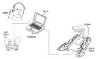
- autonomous behaviorsare implemented with a operator control unit (OCU) that is an unobtrusive, highly mobile control system providing the user with a remote vehicle operating experience that seamlessly integrates with the user's other tasks and duties.
- the OCUallows the user to initiate autonomous behaviors for the remote vehicle, and to switch between tele-operation and such autonomous behaviors.
- Basic components of an exemplary OCU, illustrated in FIG. 1include a display, an input device, a processor, an antenna/radio (for wireless communication), and software.
- a head-mounted displayprovides video display from one or more remote vehicle cameras.
- a hand-held controllerpreferably having a twin-grip design, includes controls to drive, manipulate, and monitor the robot and its payloads.
- Audiomay additionally be provided via the hand-held controller, the display, or dedicated listening devices such as, for example, Bluetooth headsets commonly used with mobile phones.
- a microphoneis provided on the hand-held controller, the processor, the display, or separately from these components, and can be used with a speaker on the remote vehicle to broadcast messages.
- a button on the hand-held controller or a soft button within the GUIcan be used to activate the speaker and microphone for broadcasting a message.
- the OCU illustrated in FIG. 1includes a suitably powerful processor including, for example, a rugged laptop or a tablet PC.
- the processorcommunicates with the remote vehicle wirelessly or via a tether (e.g., a fiber optic cable).
- the processoradditionally communicates with the hand-held controller and the display either wirelessly or using a tether.
- the processorincludes software capable of facilitating communication among the system elements and controlling the remote vehicle.
- the softwareis a proprietary software and architecture, including a behavioral system and common OCU software, which provide a collection of software frameworks that are integrated to form a basis for robotics development.
- this softwareis built on a collection of base tools and the component framework, which provide a common foundation of domain-independent APIs and methods for creating interfaces, building encapsulated, reusable software components, process/module communications, execution monitoring, debugging, dynamic configuration and reconfiguration as well as operating system insulation and other low-level software foundations like instrument models, widget libraries, and networking code.
- the processorperforms all of the data processing for the control system.
- the hand-held controllerincludes a button, toggle-type switch, or other similar mechanism for switching among button function modes.
- the button function modescan include, for example:
- the left joystickis used to steer the robot forward, back, left, and right
- the left button arrayis used to control the attack camera (for a robot having, for example, a drive camera and an attack camera)
- the right joystickcontrols a spooler (for example containing fiber optic cable)
- the right button arraycontrols a variety of functions such as the camera zoom, robot lights, robot speed, an camera choice (allows user to choose one or more cameras as, for example, primary and secondary)
- the right shoulderis for flipper control.
- Manipulate (Gripper) Modethe left joystick is used to move the gripper forward, back, left, and right, the right joystick is used to move the gripper up and down and to fold or unfold the elbow, and the right shoulder buttons are used to rotate the gripper clockwise and counterclockwise.
- Target (Attack Camera) ModeThe left joystick is used to move the attack camera forward, back, left, and right, and the right joystick is used to move the attack camera up and down.
- the left joystick folds and unfolds the gripper shouldere.g., using the top and bottom buttons
- rotates the turret clockwise and counterclockwisee.g., using the right and left buttons
- the left button arraycontrols the attack camera
- the right button arraycontrols a variety of functions such as the camera zoom, robot lights, robot speed, and camera choice.
- the right shoulder buttonsare used to rotate the gripper clockwise and counterclockwise.
- GUI NavigationThe left joystick navigates a cursor up, down, right, and left, the left button array moves the menu itself up, down, left, and right, and the right button array includes cancel and select functions.
- buttonsmay maintain the same functions, such as the top left button of the center button array being a pause/brake button, and the top right button of the center button array being a menu button.
- the button to change among the above functional modesmay remain the same.
- the left joystickis always used to drive the remote vehicle and the directional pad is always used to navigate soft buttons of a graphical user interface (GUI).
- GUIgraphical user interface
- a GUI facilitating simplified control of one or more remote vehiclesis displayed to the operator on one or both of the processor display and/or the head-mounted display.
- FIG. 2illustrates an exemplary embodiment of a displayed GUI.
- the main imageis a video stream from the robot's attack camera and the smaller image in the lower right corner is video stream from the robot's drive camera.
- the status of the attack camera(e.g., front zoom) is displayed in the upper left corner, and certain camera control icons or soft buttons are presented under the camera status.
- the iconsinclude zoom in, zoom out, IR filter on/off, IR light off/low/medium/high, camera default position (designated in this embodiment as a V in a sun shape), camera setting choices, audio choices, snap shot, and video record on/off
- the GUIpops up a screen to select among a variety of setting options.
- the robot's namecan be displayed (illustrated herein as “Name567890123456”).
- Additional icons or soft buttonscan be displayed, for example on the right side of the GUI.
- the icons or soft buttonscan include, from top to bottom, status of communication link (between the remote vehicle and the OCU), battery charge level (for the remote vehicle and the OCU), speed toggle (wherein the snail icon indicates that the remote vehicle is in a slow range of speed within the available scalable range of speed), robot heading, two icons indicating the robot's position and heading, and a variety of autonomous behavior options such as predefined poses.
- the OCUhas two states (on and off) and three modes: (1) training mode; (2) operation mode; and (3) maintenance mode.
- most of the system functions, including the exemplary functions listed in the table below,are performed in all three modes.
- Power On/off StatusCommunicate communicate with robot status of communications tethered and wireless communication
- microphone control on/off/speak speaker control on/off/volume request information/status/data illumination on/off/other select optionsselect robot payload control map controls (autonomous robots or assistance) autonomy controls
- Remote vehiclescan utilize a number of autonomous behaviors that can be implemented automatically or via the control system, such as via the GUI icons described above.
- Such behaviorscan be categorized as: (1) ballistic behaviors that autonomously execute once within a defined operating period; (2) semi-ballistic behaviors that execute once within a defined operating period and that operate autonomously while allowing for manual control during execution; or (3) persistent behaviors that execute continuously and autonomously while allowing the operator to manually control other behavior(s) of the remote vehicle.
- the autonomous behaviorsmay begin by either responding to sensor output and autonomously starting the behavior, responding to operator input via the depression of a key, soft key, or other actuator included the control system described above, or by responding to other behavior output.
- An embodiment of the present inventionprovides the operator with varying levels of autonomy so that the operator may control the remote vehicle at times and choose to allow the remote vehicle to operate autonomously at times or concurrently.
- FIG. 3is a block diagram illustrating an exemplary embodiment of various autonomous behaviors.
- the main autonomous behavior 7050identifies in memory three main subtypes of behaviors: ballistic behaviors 7065 , semi-ballistic behaviors 7092 and persistent behaviors 7053 .
- Ballistic behaviors 7065comprise a particular behavior routine that executes for a finite period of time when the behavior is activated.
- Exemplary ballistic behaviors 7065include: stair climbing 7068 , preset action sequence 7071 , click-to-drive or click-to-grip 7074 , custom pose presets 7077 , autonomous flipper routine 7078 , retro traverse 7080 , and self-righting 7083 . Click-to grip, retro traverse, and self-righting behaviors are described in further detail below.
- FIG. 4is a flow diagram illustrating an activation routine used to activate a ballistic behavior and its associated routines.
- the operatorcan select the behavior using the OCU, for example by pressing a button.
- the OCUcalculates a command 804 representative of the pressed button and sends the command to the remote vehicle.
- the remote vehicle's control system 1155executes a routine to determine if the behavior is compatible 806 with the remote vehicle's current state. Determining compatibility can include evaluating all sensor data to determine whether or not the remote vehicle's position within its environment, the current internal state of the remote vehicle, the current operational behavior on the remote vehicle, and/or the remote vehicle's environment are incompatible with the chosen behavior. If the behavior is not okay to run (not permitted), the remote vehicle can generate feedback information 808 that is sent to the user, alerting the user to the behavior's incompatibility. The behavior activation routine is then exited 824 .
- the remote vehiclecan change the start condition of the chosen behavior to a positive value 810 , causing the behavior to turn on. Once turned on, the behavior sends a vote to the arbiter 812 requesting control of its associated actuators. If the behavior has a higher priority than the behavior currently in control of the actuators 814 , the remote vehicle will gain control of the actuators and wait for a second start condition (explained further below). If the behavior doesn't have a higher priority than the behavior currently in control of the actuators 814 , the behavior will wait 816 , and send another vote 812 to the arbiter. The behavior will continue to do this until it gains control of the actuator.
- the software routines included within the behaviorwill execute 822 .
- the routineswill alter the behavior's start conditions to a false or stop status effectively halting the behavior 824 .
- a second start condition check 818is included to accommodate those behaviors that may be in a perpetual start mode, but that are not activated until they receive particular sensor information. Alternatively, the second start condition check 818 could be used to activate routines within behaviors that are currently in an “on” state.
- persistent behaviors 7053include behaviors that can be turned on and kept on via an always true first start condition.
- a persistent behavioris activated via a proper second start condition.
- Persistent behaviors 7053start when the remote vehicle is powered up and can be stopped via an OCU command.
- An embodiment of the inventionincludes a persistent behavior set 7053 including an obstacle avoidance 7059 behavior. While shown as a semi-ballistic behavior in FIG. 3 , cruise control can alternatively be a persistent behavior.
- FIG. 5is a flow chart illustrating a routine to activate or de-activate a persistent behavior.
- the operatoractuates an OCU button, switch, etc. generating a signal that is used to calculate a representative command that is sent to the remote vehicle via a communication connection.
- the remote vehicle's control system 1155relays the command to the proper behavior, which causes the behavior's first start condition to be altered.
- the commandindicates that the persistent behavior should be turned on, the start condition will be changed to a positive or “on” condition.
- the commandindicates that the persistent behavior should be turned off, the start condition will be changed to a negative or “off” condition.
- the persistent behaviorwill either start or stop 865 .
- persistent behaviorshave an initial positive start condition, an operator will need to turn off the behaviors after the remote vehicle is powered up to keep the persistent behaviors from executing in response to system and sensor output.
- FIG. 6illustrates the execution of routines within a persistent behavior when the routines' second start condition is activated by system or sensor output.
- the flowchart in FIG. 6assumes that the persistent behavior's first start condition is true, and has been true as a function of its “always on” characteristic.
- sensor or system outputmust be sent 867 to the persistent behavior by the remote vehicle's control system 1155 . If such output is of the type that will cause the remote vehicle's second start condition to become positive, the persistent behavior's second start condition flag will be changed 871 to a positive or start value and the persistent behavior will begin to send votes 873 to the arbiter to gain control of the behavior's associated actuators and manipulators. If the behavior has a higher priority than the behavior currently in control of the actuators 873 , then the behavior will gain control of the actuators.
- the behaviorwill wait 878 , and send another vote 873 to the arbiter. The behavior will continue to do this until it gains control of the actuators or manipulators. Should the behavior have control of the actuator, the routine within the behavior will execute 879 . The routine will continue to execute until it loses control over the actuators 885 , in which case one of the first or second start condition flag is changed to a negative or stop value 887 which causes the behavior to stop 883 . If the first start condition flag changes to a negative or stop value, the behavior is disabled. In an embodiment of the invention, the behavior can thereafter be restarted using the routine displayed in FIG. 5 . If the second start condition flag is changed to a negative or stop value, the behavior will stop until it detects sensor or system output that causes the behavior to start again.
- steps 879 through 887 of FIG. 6may be substituted into the ballistic and semi-ballistic routines for steps 848 and/or 822 .
- FIGS. 7A and 7Billustrate an embodiment of a remote vehicle of the present invention.
- a mobile robot 10has a head 122 that includes a drive camera 127 mounted thereon to provide visual information regarding the environment of the mobile robot 10 , an electro-optic infrared (EO/IR) module 4165 which uses LIDAR to map the environment and detect possible obstacles, main drive treads 110 for propelling and steering the mobile robot 10 , and robot-mounted antennae 131 for communicating with an operator via the control system.
- the mobile robot 10also includes rotatably extensible, treaded flippers 115 that can be deployed to augment traction and to overcome obstacles, and a robotic gripper 150 for grasping or manipulating objects in the mobile robot's environment.
- the mobile robot 10further includes an attack camera 151 to aid in navigation of the mobile robot and the robotic gripper 150 .
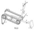
- FIG. 8illustrates a mobile robot with both its robotic gripper 113 and attached upper arm 112 and lower arm 111 extended. Further shown is the extension of an arm 118 connected to the head 117 , and the extension of the head 117 from the arm 118 . Also shown is the advantage of having an attack camera 114 attached to the gripper's upper arm 112 . The attack camera 114 is able to display the gripper's position within its environment in relation to the position of the gripper's upper arm 112 . Using this information, the user can adjust the upper arm 112 to reposition the gripper 113 in its environment. Further shown is an extended flipper 116 which shifts the mobile robot's center of gravity.
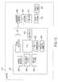
- FIG. 9is a block diagram depicting an exemplary implementation of a mobile robot control system.
- the control system 1155includes a single board computer (SBC) 1110 .
- a microprocessorcan be used in lieu of the single board computer 1110 .
- Connected to the SBC 1110is a global positioning system (GPS) module 1135 , a radio module 1150 , and a wireless Ethernet transmitter and receiver 1140 .
- a radio module 1150is connected to the SBC 1110 via an Ethernet switch 1190 , and is further connected to a radio antenna 1145 .
- the usercan control the control system 1155 using a radio communicating over a secure connection created by the radio module 1150 and the radio antenna 1145 .
- GPSglobal positioning system
- control system 1155Further included in the control system 1155 is a power supply 1115 and memory 1125 including any combination of ROM, volatile, and non-volatile memory. Also connected to the SBC are network 1 transmitter and receivers 1120 , 1121 , 1122 and a network 2 switch 1130 .
- the network 1 transmitter and receivers 1120 , 1121 , 1122provide communication between the control system 1155 and an actuator assembly 1165 via a first connection wire 1187 installed between the first network 1 transmitter and receiver 1122 and second neck 1191 and a second connection wire 1186 installed between the second network 1 transmitter and receiver 1120 and first neck 1194 .
- the network 1 transmitter and receivers 1120 , 1121 , 1122also provide communication between the control system 1155 and the chassis 1160 via a third connection wire 1181 installed between the third network 1 transmitter and receiver 1121 and the chassis 1160 .
- the network 2 switch 1130provides communication between the network 2 switch 1130 and each of the chassis 1160 , the first neck 1194 , and the second neck 1191 via a first connection link 1180 , a second connection link 1188 , and a third connection link 1180 , between the chassis 1160 , first neck 1194 , and second neck 1191 , and the network 2 switch 1130 .
- a chassis assembly 1160Connected to the control system 1155 is a chassis assembly 1160 as well as an actuator assembly 1165 .
- the actuators included in the actuator assembly 1165are a first neck 1194 connected to a head module 1195 , and a second neck 1191 connected to a third neck 1192 which is further connected to a gripper module 1193 .
- Each of the necks 1194 , 1191 , 1192can include a substantially similar hardware circuit and software routine architecture 4301 .
- the actuator modules within the actuator assembly 1165are connected to the control system 1155 via connection wires 1187 , 1186 , and connection links 1189 , 1188 .
- the chassis 1160is connected to the control system 1155 via a connection wire 1181 , and a connection link 1180 .
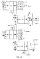
- chassis assembly 1160An exemplary implementation of a chassis assembly 1160 is described in the block diagram shown in FIG. 10 .
- the chassis 4001 base circuit 4055includes an FPGA 4035 connected to a network 1 transmitter and receiver 4050 , and a network 2 switch 4045 .
- power regulators 4015including circuits configured to manage power within the chassis 4001 .
- motor drivers 4030included in the base circuit 4055 for motion control are motor drivers 4030 , motor encoders 4025 , and a motor battery charger 4020 .
- the chassis 4001also includes a number of motion control components connected to the base circuit 4055 , including incremental encoders 4060 , drive motors 4065 , a brake 4070 , thermistors 4075 , and hall sensors 4080 .
- FIG. 11A block diagram of an exemplary implementation of a neck module 4301 is shown in FIG. 11 .
- the neck module 4301includes a base circuit 4305 having an FPGA 4330 connected to a first network 1 transmitter and receiver 4315 , a second network 1 transmitter and receiver 4360 , and a network 2 switch 4320 . Included within the base circuit 4305 are power regulators 4340 that are circuits configured to regulate power within the neck module.
- the first and second network 1 transmitter and receivers 4315 , 4360are connected to a payload connector 4310 , 4355 .
- the payload connectors 4310 , 4355are plugs configured to mate with a corresponding plug on a payload such as an additional neck module 1191 , 1192 , a head module 1195 , or a gripper module 1193 .
- a clavical encoder 4345Further included within the base circuit 4305 , to aid in motion control, are a clavical encoder 4345 , a tilt 1 encoder 4350 , half-bridge drivers 4365 , and h-bridge drivers 4370 .
- Additional motion control components included within the neck module 4301 and connected to the base circuit 4305are brushless motors 4385 , hall sensors 4380 , and a thermistor 4375 .
- the neck module 4301is also connected to a pan module 4390 and a tilt module 4395 .
- the pan module 4390allows the user to pan the distal portion of the neck about the neck's pivot point
- the tilt module 4395allows the user to tilt the distal portion of the neck about the neck's pivot point.
- FIG. 12A block diagram of an exemplary implementation of a head module 4100 is shown in FIG. 12 , and includes a base circuit 4105 with a centrally located FPGA 4125 . Connected to the FPGA 4125 are a network 2 switch 4130 , and a network 1 transmitter and receiver 4120 which is further connected to a payload connector 4190 .
- the payload connector 4190is a plug configured to mate with a corresponding plug on a neck module 4301 such as neck module 1 1194 .
- Included in the base circuit 4105are power regulators 4110 that are circuits configured to manage power within the head module 4100 .
- the base circuit 4105is connected to a set of video decoders 4150 via a CCIR-656 video communication bus 4145 and a serial bus 4140 .
- Input to the video decoders 4150includes: (1) the output from a drive camera 4160 ; (2) the output from a differential NTSC receiver 4155 which is further connected to the head module connector 4156 ; and (3) the output from the electro-optic infrared (EOIR) module 4165 .
- Output from the EOIR module 4165includes a near infrared (NIR) 4170 camera, a long wave infrared (LWIR) 4175 camera, and a laser range finder 4180 .
- NIRnear infrared
- LWIRlong wave infrared
- FIG. 13An exemplary implementation of a gripper module 1193 is shown in the block diagram of FIG. 13 .
- a FPGA 4240Located within the base circuit 4210 of the gripper module 4201 is a FPGA 4240 connected to a network 2 switch 4245 , and network 1 transmitter and receiver 4235 that is further connected to a payload connector 4230 .
- the payload connector 4230is preferably a plug configured to mate with a corresponding plug on neck module 3 1192 .
- power regulators 4220including circuits for regulating power within the gripper module 4201 , and the following components for motion control: gripper encoders 4215 ; half-bridge drivers 4255 ; and h-bridge drivers 4260 .
- Additional motion control components connected to the base circuit 4210 and included within the gripper module 4201are brushless motors 4285 , hall sensors 4280 , and a thermistor 4275 .
- a video decoder 4265is also connected to the base circuit 4210 .
- An attack camera 4270 located proximate to the gripper 4201creates input to the video decoder 4265 so that the user can view the gripper 4201 actions.
- FIG. 14illustrates an exemplary implementation of a network installed between the head 4401 and the control system 4409 and the chassis 4406 .
- the networkincludes a control system 4409 with a SBC 4436 for processing information transmitted to the computer 4436 by each network.
- the SBC 4436is connected to a single Ethernet switch 4427 which in turn is linked to an Ethernet switch 4427 within the neck 4403 via a communication link 4415 and an Ethernet switch 4427 within the chassis 4406 via a communication link 4415 .
- the SBC 4436connects to two RS485 transmitter and receivers 4430 , one transmitter and receiver 4430 is connected to a RS485 transmitter and receiver 4430 in the neck 4403 via a connection wire 4412 , and a second transmitter and receiver 4430 is connected to a RS485 transmitter and receiver 4430 in the chassis 4406 via a connection wire 4412 .
- Each actuator assemblycan include a core circuit capable of implementing an alternative network that includes only an Ethernet network.
- the core circuitincludes a field programmable gate array 4418 with a media access controller 4433 , where the FPGA is capable of managing multiple digital input 4421 and is further programmed to interface with the media access controller (MAC), which includes information or commands generated either by the FPGA or the digital I/O 4421 to generate frames of data to be sent to other modules within the robot via packets sent by the Ethernet switch 4427 .
- the MACis able to parse frames of data included within packets it receives from the Ethernet switch and extract information or commands that are either processed by routines included within the FPGA or relayed to the digital I/O 4421 .
- the MACDue to the full duplex communication network created by the Ethernet switch 4427 , the MAC is able to simultaneously transmit and receive packets of data.
- the RS485 transmitter and receiver 4430is half duplex communication meaning that the transmitter and receiver 4430 cannot transmit data and receive data simultaneously.
- Actuator assemblyrefers to the head 4401 , the neck 4403 or the chassis 4406 .
- Modulerefers to a component within the head 4401 , the neck 4403 , the control system 4409 , or the chassis 4406 .
- Each Ethernet switch 4427is also connected to a payload 4424 , wherein payload can include a drive assembly, an EO/IR, or other assembly.
- payloadcan include a drive assembly, an EO/IR, or other assembly.
- Use of an Ethernet switch 4427allows for simultaneous communication between the payload 4424 and other modules within the network including the head 4401 , neck 4403 , and chassis 4406 .
- An example of thiswould include video information transmitted from a payload 4424 such as the video decoders 4150 .
- the form of such informationis a constant stream of video feedback from the drive camera 4160 .
- the exemplary network created using the Ethernet switch 4427allows for simultaneous receiving of video information from the drive camera 4160 and transmitting and receiving of information from the single board computer 4436 .
- FIG. 15illustrates an embodiment of an Ethernet endpoint block 4439 including an FPGA 4418 configured to include a MAC and connected to an Ethernet switch 4427 .
- the Ethernet switch 4427is connected to the MAC included on the FPGA 4418 via a medium independent interface bus that provides a logical interface with a communication protocol selecting the line speed and whether the connection is in a half or full duplex mode.
- the MACparses the I/O ports 4445 included on the FPGA and generates frames of data to be included in packets. The packets are transmitted out through the Ethernet switch 4427 to the rest of the modules in the network. Included on the Ethernet switch 4427 are physical devices or line interfaces that handle the transfer of data from the Ethernet cable to the Ethernet switch 4427 .
- An oscillator 4442is included to facilitate the exchange of information between the MII buses.
- FIG. 16illustrates an exemplary embodiment of the present teachings using the Ethernet endpoint block in the chassis, neck, head and EO/IR payload. Also shown is the connection of various payloads to the Ethernet endpoint block as well as the running of Ethernet to other modules.
- FIGS. 17A and 17Billustrate an embodiment of a robotic arm 900 for functioning as a gripper affixed to the mobile robot 10 .
- the illustrated robotic arm 900includes a base 925 with circuitry required to control the arm. Additionally, the arm 900 includes a pair of actuators 920 installed toward the end of the arm and able to grip and manipulate objects. Further included near the actuators 920 are joints 915 , 910 which may be mobilized to alter the position of the actuators 920 in space, and a camera 905 installed proximate the actuators 920 so that the operator may control actuator 920 movement based on video feedback.
- the actuatorsare connected to a secondary arm 930 that pivots at a joint 901 and is connected to a main arm that pivots at a joint 940 .
- the joint 940 connected to the arm base 925 and the primary arm 935can be controlled by the operator via an OCU outlined above.
- a drive commandis sent to the drive assembly located proximate the joint 940 which in turn causes a motor located in the drive assembly to mobilize actuators connected to the joint 940 via gears and subsequently mobilize the primary arm 935 .
- drive commands sent to the drive assembly located proximate the joint 901 connecting the primary arm 935 to the secondary arm 930can cause a motor located in the drive assembly to mobilize actuators connected to the joint 901 via gears and subsequently mobilize the secondary arm 930 .
- Joints 915 , 910capable of mobilizing the manipulators 920 located on the gripper, can also be actuated via drive commands sent to a drive assembly proximate the joint 915 and including a motor. Additionally, the camera 905 installed near the gripper actuators 920 can input video data regarding the gripper's environment and transmit the data to the OCU 1155 where it is further transmitted so that the operator can view the gripper's environment.
- a remote vehiclehas included within its control system 1155 a behavior system comprising software routines and circuits.
- FIG. 18illustrates an exemplary implementation of a behavior system for a remote vehicle.
- behaviors 715including different behavior software routines and subroutines.
- each behaviorincludes a status check routine that constantly checks sensor input to determine a change in start condition.
- the behaviorinitiates a routine, included within the behavior, that sends software commands to an arbiter (coordinator) 710 .
- the commands sent to the arbiter 710are votes telling the arbiter 710 that the behavior would like control of the actuators used by the behavior's routines.
- FIG. 19illustrates an exemplary priority listing for behaviors within a system in accordance with certain embodiments of the present teachings.
- a behaviorsuch as obstacle avoidance 7059 has a higher priority than stair climbing 7068 as it can be more important that the remote vehicle avoid an obstacle than climb a stair.
- the arbiter 710is a software routine that manages the votes and priorities of the individual behaviors 715 in conjunction with a scheduler 730 , to determine when and in what order the behaviors 715 will gain control over the remote vehicle's actuators and manipulators. To accomplish this, the arbiter 710 reviews the behaviors 715 currently voting for control and each behavior's priority level. Optionally, the arbiter may also review a scheduler's indication of which behavior should gain control based on the length of time that a current behavior or past recorded behavior had control of the actuators and manipulators.
- Certain embodiments of the present teachingsinclude virtual sensors 720 in communication with sensors 725 that can include sensor components and related circuitry and software routines providing feedback representing the remote vehicle's current external and internal environment. Sensor output can be conditioned by virtual sensors 720 , which can include circuits and software able to receive and process sensor signals and provide outputs representative of each signal, but in a form able to be processed by the behavior routines.
- actuators 705able to respond to output from virtual actuators 701 by mobilizing and performing actions.
- the behaviors 715output control commands that can include drive commands, communication commands, and other commands to control robot actuators.
- Each actuatoris able to receive drive commands in a particular format.
- the virtual actuators 701include software routines and circuits that can convert the software control commands to control commands receivable by the actuators 705 .
- the autonomous behaviorsare included on the remote vehicle in memory, and are executed by the SBC.
- the present teachingscontemplate employing autonomous behaviors on a variety of remote vehicle types, although an exemplary implementation including a mobile robot is describe below.
- the robotincludes two “fire and forget” behaviors allowing an operator to chose a displayed destination pixel and either drive toward the destination or grip an item at that location. These behaviors allow an operator to accomplish complex actuation and driving with less intervention.
- the click-to-grip behavioruses image data from first and second cameras displayed in respective first and second windows 261 , 262 (see FIG. 20 ) to identify a target object to be gripped.
- the operatoractuates a click-to-grip behavior and positions the first and second selectors 267 , 268 to identify the target object 3010 in a drive camera display 261 and an attack camera display 262 .
- FIG. 21illustrates an embodiment of a click-to-grip routine.
- the routineUpon operator selection of the object, the routine stores the image coordinates from the attack camera video display 8103 and the drive camera video display 8106 . Using these image coordinates and stored values corresponding to the resolution of the cameras, the routine calculates the destination point 8109 . The coordinates are projected into the robot's current environment 8112 and a set of rays are calculated 8115 from the projected coordinates. The rays represent travel vectors from the robot's current position to the destination position. The rays are corrected 8118 and a check is done to ensure that the gripper is on the correct side of the turret 8121 .
- the robotmoves the gripper 8124 . Once the gripper is correctly positioned, a check is done to ensure that the drive camera is synched with the object to be gripped 8130 . If the drive camera is not synched, the robot can reposition the camera 8127 , which may include moving the camera to a position included within the newly-calculated travel vector. Once the drive camera is synched, the robot moves the gripper to the destination point 8133 and grips the object 8136 .
- the remote vehiclecan sense and avoid collision of the manipulator arm with the frame. To do so, collision avoidance determines the end effector motion that best matches the user's command while avoiding remote vehicle self collision. In certain embodiments, the remote vehicle maintains a 3D geometric model of itself to know its current state and what component is potentially colliding with what. To prevent unintended manipulator arm-ground collisions, parts of the manipulator arm typically not visible to the operator are maintained above an artificial ground plane. Because obstacle avoidance can sacrifice a user's intended spatial trajectory to avoid collision, a potential field strategy can be employed to create a gradient with a positive attraction to the user's goals and a negative attraction to self collision. Such automated collision avoidance allows the user to operate a gripper more intuitively with respect to the viewers own coordinates rather than those of the remote vehicle chassis. To do so, a lower tilt camera of the remote vehicle automatically tracks the gripper, freeing the user from manual adjustment.
- Gripper motion in the viewer perspectivecontemplates commands being given to the remote vehicle in the camera's coordinate frame, which creates a consistent, intuitive interface for manipulator control.
- the usercan center the object in his or her own viewscreen using a consistent 2D up/down, left/right control.
- the operatorcan use a forward/back command to move the manipulator toward or away from the object.
- This interfacecan remain the same regardless of manipulator configuration, so gripping objects on the ground can seem the same as opening a door.
- Movements in the camera's frame for any camera configurationare converted to end-effector movement. Certain embodiments accomplish this using basic forward kinematics to obtain the camera's frame orientation relative to the remote vehicle's root frame. The camera frame movement is rotated into the remote vehicle's root frame and the root frame movement is applied to the end effector's frame.
- Autonomous camera followingadds autonomous control of the secondary (e.g., lower tilt) camera, enabling it to keep the end-effector in sight.
- Thiscan give the user depth perception by presenting triangulated viewpoints of the end effector on the PCC.
- the cameracan track constantly or minimize movement while keeping the end effector centered.
- the systemmust determine both the position of the end effector and where to aim the camera to point at the end effector. To do this, in accordance with certain embodiments, the dot product is used to obtain the angle between the vector representing where the camera is pointing and the vector from the camera to the end effector. That angle is then minimized.
- the present inventioncontemplates embodiments wherein the click-to-grip behavior is operable in a high degree of precision mode and a low degree of precision mode.
- the high degree of precision modeallows the operator to choose the object's corresponding pixel image on the display screen and responds to the actuation of a button triggering a gripping sequence that takes the precise pixel location and converts it to a destination point.
- the low degree of precision modeallows the operator to choose a heading direction and responds to actuation of button triggering a sequence that flies the gripper in the general direction of the objects included within the heading.
- the grippercan move using a “fly in motion,” in which the gripper moves forward in a single fluid motion actuating all necessary joints to keep the direction of movement uniform.
- the robotcan choose a path within an approved heading that provides the most direct route and avoids obstacles. The gripper will stop if it encounters unexpected obstacles, and will move forward 50% of the estimated distance to reduce the risk of over-travel. After moving 50% of the estimated distance, the operator may reposition the gripper and trigger the click-to-grip behavior again.
- the present teachingscontemplate moving away from the object using the same path that was used to move the gripper forward.
- An alternative embodimentmoves forward 100% of the estimated distance. Further alternatives include a robot that:
- the distance sensorhas a distance sensor to provide distance feedback used by the routine to adjust movement toward the object to be gripped.
- Retro traverse behaviorautonomously navigates a remote vehicle back along a return path interconnecting various previously traversed coordinates.
- the retro traverse behaviormay be activated by user request or automatically when trigger conditions are detected by the remote vehicle 10 , such as when no control signal has been received after a threshold period of time. If automatically triggered, retro traverse acts as a persistent behavior.
- a mobile robot 10records waypoints at intermittent times while it is moving.
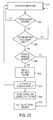
- FIG. 22illustrates an embodiment of a waypoint routine.
- the routinereceives the values for variables min_dist (the minimum distance by which successive waypoints should be separated), wait_interval (the period of time the routine should wait before recording a next waypoint) and pres_coord (the present coordinates of the mobile robot 10 , as provided by a position reckoning system), and step 2102 initializes several variables, setting init_time (the initial timestamp) and pres_time (the current time of the present execution cycle) to zero, and prev_coord (the coordinates ascertained for the previous execution cycle) and pres_coord (the currently ascertained coordinates of the mobile robot 10 ) to zero, as well.
- min_distthe minimum distance by which successive waypoints should be separated
- wait_intervalthe period of time the routine should wait before recording a next waypoint
- pres_coordthe present coordinates of the mobile robot
- step 2103It is determined at step 2103 whether the robot is moving and, if not, the process loops back to step 2103 . Otherwise, step 2104 gets the current time (such as from a clock or cycle counter) and stores it to the variable pres_time. It is then determined at step 2105 whether sufficient time has passed since the initial time and, if not, the process returns to step 2103 . If sufficient time has passed, then step 2106 assigns the value of pres_time to the variable init_time; step 2107 ascertains the present coordinates of the mobile robot 10 and stores them to the variable pres_coord; and step 2108 calculates the distance between the mobile robot's current position and the position of the mobile robot 10 ascertained at the immediately previous cycle.
- step 2104gets the current time (such as from a clock or cycle counter) and stores it to the variable pres_time. It is then determined at step 2105 whether sufficient time has passed since the initial time and, if not, the process returns to step 2103 . If sufficient time has passed, then step
- step 2109determines that not enough distance has been traversed since the previous cycle, then the process returns to step 2103 . Otherwise, step 2110 appends the values of pres_coord (as a positional record) and pres_time (as the corresponding timestamp) to the list of recorded waypoints; step 2111 sets the value of prev_coord to the same value as pres_coord; and step 2112 updates the variable wait_interval, if necessary or appropriate, before returning to step 2103 .
- the waypoint routinemaintains a list of recorded waypoints separated by at least minimum permitted differences in time and distance.
- the retro traverse behaviorcan then utilize the list of recorded waypoints to generate a return path interconnecting the waypoints, in reverse order of timestamps.
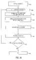
- FIG. 23illustrates an exemplary embodiment of a method for performing a retro traverse behavior.
- step 2201it is checked whether the behavior is active and, if so, the behavior proceeds to step 2202 (otherwise looping back to step 2201 ).
- step 2202sets the values of retro_start and prev_retro_start to zero.
- Step 2203erases any previously used waypoints, and step 2204 ascertains the current position of the robot 10 and the current time, which are prepended to the list of recorded waypoints.
- step 2205it is determined whether a control signal has been properly received. If so, then step 2212 proceeds to navigate the robot based on the instructions received from the operator. Otherwise, step 2206 sets the value of prev_retro_start to retro_start, and prev_retro_end to retro_end. Step 2207 sets the value of retro_start_time to the current time, and step 2208 navigates the robot 10 toward the next previous waypoint retrieved from the list of recorded waypoints for one execution cycle. If step 2209 determines that communication has not been restored, the behavior returns to step 2208 and continues navigating toward the waypoint. Otherwise, step 2210 sets retro_end_time to the current time and step 2211 inserts a new entry (comprising the values of retro_start_time and retro_end_time) into a list of retro traverse intervals before proceeding to step 2212 .
- the retro traverse behaviorcan ignore any waypoints that are recorded during retro traverse operation, as these are spurious for future retro traverse purposes. That is, after the robot 10 has finished a retro traverse, it records the range of timestamps on the points it retraced and that it created on its path back. On its next retro traverse, it may ignore those points.
- FIG. 24An exemplary remote control operation of the mobile robot 10 in an urban combat zone is shown in FIG. 24 .
- An operator 5is positioned within a sandbag-enclosed bunker 9012 adjacent a roadway.
- the mobile robot 10proceeds out from the bunker 9012 , under control of the navigation commands transmitted, preferably wirelessly, by the operator. As shown by the curved dotted line, the mobile robot 10 then traverses a path between various buildings 9011 .
- Each recorded waypointincludes information regarding the position of the mobile robot and a timestamp indicating when the position was sampled.
- the waypointsmay be recorded in the memory of the mobile robot 10 in a suitable data structure (e.g., as a doubly-linked, indexed list, sorted chronologically by timestamp) to permit forward and reverse list traversal as well as indexed access to the waypoints.
- the mobile robot 10may fail to receive control signals transmitted by the operator. Therefore, as an example of a persistent autonomous behavior, the retro traverse behavior may be activated by the robot 10 when it determines that communication is lost.
- FIG. 25AAnother embodiment of a retro traverse behavior is illustrated in FIG. 25A , in which the robot traverses either forward or backward along a single line 2300 .
- the robot 10initially proceeds out along the line 2300 during a first outbound leg 2301 .
- FIG. 25Billustrates an embodiment of the invention that continues from the example shown in FIG. 25A .
- This pruned listcorresponds to the desired straight path back to the beginning of the journey.
- the mobile robot 10may base its navigation on a lookahead vector.
- a lookahead vectorcan be defined in the following way: a starting point lies at the closest point on the path to the mobile robot 10 , and an ending point is a point farther along the path that is either at a maximum distance away, or at a shorter distance as determined by the curvature of the path and/or other factors.
- the mobile robot 10may continuously drive toward a virtual point approximately 1 meter in front of it along the intended path.
- the distance that the mobile robot 10 looks aheadmay be variable, depending upon the geometry of the lookahead vector.
- navigation of the mobile robot 10may utilize a line-segment abstraction of the intended path.
- the return pathcan be represented as a set of piecewise continuous, conjoining line segments rather than a set of points.
- the mobile robot 10may perform most of its calculations in terms of the tangent and perpendicular to the line segment the mobile robot 10 is traversing instead of based on the vector difference to the next waypoint. Accordingly, the mobile robot 10 may reduce or eliminate sharp turning when it approaches waypoints conjoining two path line segments at acute angles.
- a pointcan be expressed as a distance along the path. For example, letting ⁇ represent the tangent unit vector to the i th line segment, then a point r with path length l has a position
- the retro traverse behaviormay implement a predetermined cycle of calculations to follow a return path:
- the calculationsmay be done in the listed order during a cycle of the behavior system because the mobile robot 10 moves after all of the calculations have been completed.
- the retro traverse behaviormay use a radius of interception to determine whether the mobile robot 10 has reached a waypoint, or a perpendicular plane to determine when the mobile robot 10 has passed a waypoint.
- the mobile robot 10keeps track of which line segment of the return path it is traversing. Since the lookahead vector keeps track of the local area that the robot's motion is based on, the only line segments of the retro traverse path that the robot needs to consider are those spanned by the lookahead vector. The retro traverse behavior then determines the closest of these line segments and sets that as its reference.
- FIG. 26Aillustrates an embodiment of the invention where the lookahead vector 2410 extends from the mobile robot 10 along a linear return path including a first line segment 2401 and second line segment 2402 interconnecting waypoints A, B and C.
- the mobile robot 10computes its distance to all the line segments between the beginning and the end of the lookahead vector 2410 .
- the line segment closest to the mobile robot 10is the one it associates with.
- the robotassociates to the first line segment 2401 via the perpendicular line 2411 .
- third and fourth line segments 2403 , 2404 interconnecting waypoints D, E and F,form an angle with waypoint E as the corner.
- the mobile robot 10determined it was closest to the third line segment 2403 , and thus the lookahead vector 2410 starts there for the present cycle. However this time it finds that it is closest to the fourth line segment 2404 , meaning it has passed waypoint E.
- FIG. 26Cillustrates a situation similar to the arrangement of FIG. 26B ; however, in FIG. 25C , the lookahead vector—which is rooted in the fifth line segment 2405 —does not extend all the way out to the closest point on the sixth line segment 2406 .
- the mobile robot 10should not associate with the sixth line segment 2406 because then the mobile robot 10 would short cut the desired path.
- the lookahead vectorpreferably gets shortened in order to avoid taking short cuts that bypass waypoints. To achieve proper paths without shortcutting, the retro traverse behavior does not accept any line segments for which the closest point to the mobile robot 10 is beyond the end of the lookahead vector.
- the mobile robot 10stays on the fifth line segment 2405 despite it being farther away than the sixth line segment 2406 . Once the mobile robot 10 has determined which line segment it is on, it calculates the closest point to the mobile robot 10 on that line segment. This point is then used as the origin of the lookahead vector for the subsequent iteration.
- the retro traverse behaviorAfter determining the beginning of the lookahead vector, the retro traverse behavior next determines where the end of the lookahead vector is.
- the lookahead vector 2510may have a length established by default to a predetermined value (e.g. one meter long). However, the retro traverse behavior may be implemented so as to ensure that the mobile robot 10 drives at least within a maximum permitted distance of each waypoint. If the lookahead vector 2510 were to always stay at its full default length, the mobile robot 10 might traverse a route with all the curves excessively smoothed out in some circumstances.
- FIGS. 27A through 27Ddemonstrate a system for determining when and how to shorten the lookahead vector 2510 to keep the mobile robot 10 aligned with the intended path.
- FIG. 27Ashows a straight-line path comprising first and second line segments 2501 , 2502 .
- the path of mobile robot 10passes well within the permitted distance from waypoint A and accordingly, the lookahead vector 2510 may remain at its full default length.
- the mobile robot 10has moved farther along the path to a section where it angles slightly at waypoint E between the third line segment 2503 and fourth line segment 2504 . Because the mobile robot 10 will attempt to drive toward the end of the lookahead vector 2510 , the appropriate approximation of the mobile robot's path is the vector extending from the mobile robot 10 to the end of the lookahead vector 2510 .
- the retro traverse behaviorchecks whether the perpendicular distance from a waypoint to is less than the maximum permitted distance (which may be a predetermined, constant value—such as one meter, for example).
- the mobile robot 10repeats this check for every waypoint disposed orthogonally to the lookahead vector (i.e., waypoints for which there exists an orthogonal projection onto the lookahead vector).
- the mobile robot 10may repeat the distance check for every waypoint that is associated with any of the retro traversal path line segments intersected by the lookahead vector 2510 , to simplify the calculation of whether a waypoint “lies along” the lookahead vector 2510 .
- the distanceis within the permitted range; therefore, the lookahead vector 2510 extends to its full length.
- FIG. 27Cshows a similar situation; however, the full-length lookahead vector 2510 does not lead to a path that is within the permitted distance of one of the waypoints (waypoint I) that projects orthogonally onto the lookahead vector 2510 .
- the mobile robot 10therefore sets the end of the lookahead vector 2510 (which will be used in the subsequent cycle) to be the mean of the current end point and the end point of the previous lookahead vector 2511 used in the preceding cycle of the behavior.
- the retro traverse behavior running on the mobile robot 10will continue to decrement the length of the lookahead vector 2510 for several iterations in a similar manner until it either finds an acceptable end point or performs a maximum threshold number of iterations without success.
- the mean of the old and new end pointsare preferably calculated in terms of the respective path lengths of the two and then transformed into x-y coordinates, rather than averaging the x-y coordinates of the two points.
- FIG. 27Dillustrates a situation with a sharp angle between the seventh and eighth line segments 2507 , 2508 .
- the waypoint Kdoes not project orthogonally onto the lookahead vector 2510 shown in FIG. 27D . Accordingly, the retro traverse behavior preferably ensures that the closest point is actually within, to obviate this situation.
- FIG. 28illustrates an embodiment of a relationship between two output values, v_rotate and v_translate, that may be issued by the retro traverse behavior.
- the translational (v_translate) and rotational speeds (v_rotate)are calculated based on the angle by which the mobile robot 10 needs to turn to be heading toward the end of the lookahead vector.
- the rotational speedmay be determined as a PID loop on the function v_rotate shown in FIG. 28 , for example.
- the function characteristicsmay be adjusted to ensure the mobile robot 10 does not overshoot waypoints.
- the remote vehiclecan operate in three different modes: “always drive forward;” “always drive backward;” or “drive in which ever direction requires the least rotation.”
- the remote vehicleupon detecting degraded communications by examining the signal strength of a connection between the OCS and the remote vehicle and/or examining properties of the data flow between the remote vehicle and the OCU, such as percentage of dropped packets for one or more communication streams (e.g., video, telemetry, etc.), the remote vehicle can initiate a retro traverse behavior. Retro traverse can be used to return the remote vehicle to a place where communications are restored, or it can be used to return the remote vehicle to where it started.
- Retro traversecan be used to return the remote vehicle to a place where communications are restored, or it can be used to return the remote vehicle to where it started.
- Retro traversecan be implemented in the following exemplary manners:
- Alternative methods of implementing retro traverseinclude following a reduction in chemical scent or a chemical scent, and following a trail left by the robot such as a fiber optic cable, a line of spray paint, setting a destination point in a global map and traveling towards that destination point.
- Two alternative methods of implementing retro traverseinclude collecting odometric data and using it to calculate the return path and GPS waypoint collection.
- Waypoint indicationis only possible when a suitable input device is available. If the system detects a suitable input device, such as, for example, a mouse or a touch screen, the user will be able to indicate a waypoint on the OCU display and the system will provide the necessary commands to enable the remote vehicle to drive autonomously to the waypoint. The user can input a new waypoint and it will override the old waypoint. In accordance with certain embodiments, teleoperation commands also override such supervisory control. In accordance with certain embodiments where no suitable input device is detected, the vehicle can be capable of autonomously driving forward until commanded to stop or until a communication limit or maximum distance parameter is reached.
- a suitable input devicesuch as, for example, a mouse or a touch screen
- GPS, an IMU, and a navigation CPUare added to a man transportable robotic system, (MTRS) PackBot EOD robot to implement GPS-based retro traverse re-traverse and leader/follower behaviors.
- GPS receiversare typically capable of determining the robot's position accurately to within approximately 2-4 meters.
- IMUtypically can determine the orientation of the robot and has a drift rate of less than 1 degree per minute.
- the navigation CPUmay be part of a navigation payload such as an iRobot Navigator Payload that can include additional computational and sensor hardware to perform semi-autonomous behaviors such as GPS retro traverse.
- the Navigator Payloadattaches to two of the modular payload bays of a PackBot EOD in a plug-and-play fashion.
- the Navigator Payloadtypically comprises an Intel Core Duo 1.2 GHz processor, 1 GB of RAM, and an 8 GB solid-state flash memory hard drive. This CPU is used to run perception and autonomy software.
- each payloadincludes a Ublox Antaris 4 GPS receiver and a Microstrain 3DM-GX1 six-axis MEMS IMU.
- GPS receiversare typically capable of determining the robot's position accurately to within approximately 2-4 meters.
- IMUtypically can determine the orientation of the robot and has a drift rate of less than 1 degree per minute.
- the IMUdetermines the robot's rotation relative to Earth's gravitational field.
- An Unscented Kalman Filterfilters the accelerometer and angular rate information from the three-axis IMU to determine the direction of Earth's gravitational field relative to the robot.
- the UKFis an extension of the Kalman Filter to non-linear systems.
- the original Kalman Filteris a provably optimal technique for state estimation in the face of uncertainty for linear systems with Gaussian error distributions. It works by tracking the uncertainty of the system and updating both state and uncertainty using linear algebra.
- the UKFextends the filter to non-linear system by using the Unscented Transform to approximate the result of state propagation through a non-linear system by a Gaussian.
- the UKFproduces superior results to older linearization techniques such as the Extended Kalman Filter.
- the angular rate from the IMU around Earth's gravitational fieldis then used to estimate of the robot's rotation.
- Track odometry from the robotis used as a coarse measure of the robot's translation.
- a particle filteris a general state estimation technique that works for non-linear systems and non-Gaussian error models and state distributions.
- a particle filterworks by generating a number of particles, each of which is an exact hypothesis about the state of the system. The distribution of particles mirrors the probably distribution over possible system states with more particles near likely states. The particles are updated for motion and sensor input as the system evolves.
- the particle filterproduces the final estimate of the robot's pose (both location and orientation) along with error estimates.
- GPS-based leader/follower behaviorassume that the leader (a person or a vehicle) is equipped with a GPS receiver, and continuously transmits its latitude-longitude position to the robot.
- the robotwill automatically home-in on the leader's current positioning using its own GPS-based localization system.
- the robotwill maintain a specified following distance from the leader.
- retro traverse and re-traversecan be implemented with a stereo vision camera (e.g., a Tyzx G2 stereo vision camera) or the robot's attack and driver cameras. Integrate a Tyzx G2 stereo vision system with the robot.
- the G2provides 500 ⁇ 312 high-resolution 3D range data at 30 frames per second with a maximum range of 50 meters and with a range accuracy of 0-3% over a range of 0-5 meters. Error increases beyond 5 meters up to 222.4 cm at 20 meters.
- the Tyzx G2communicates with the Navigator Payload over Ethernet.
- the Tyzx stereo camerascan be mounted in an enclosure custom-designed for use with the MTRS EOD.
- GPS-denied retrotraverse and re-traverse behaviorsfunction substantially identically to the behaviors developed for GPS-based retrotraverse and re-traverse, but use odometry combined with the IMU orientation estimate to determine the robot's position.
- Stereo vision-based obstacle avoidance behaviorcan detect obstacles in the 3D range image. Obstacles can be limited to those that the remote vehicle is unable to climb over or pass under.
- the obstaclescan be stored as points in a remote vehicle-centered local perceptual space (LPS).
- LPSlocal perceptual space
- the LPScan store the locations of recently-seen obstacles, and these points can decay over time.
- a self-righting behaviorcan also be persistent, in a sense that it may constantly be running in the background to right the robot if it is up-ended. Robots traveling over very rough terrain or through opposing fire can end up flipped on their sides or even upside down. Self-righting behavior allows the remote vehicle to turn itself back over and onto its tracks so it can continue with its mission objective or return back to the operator, as desired.
- the robotsenses its orientation, for example using tilt sensors, and determines a strategy for turning itself upright. The robot will perform a progression of arm and flipper motions until it has levered itself back onto its tracks. Damage to the manipulator arm must be prevented while the remote vehicle is upside down and righting itself.
- Self rightinghas two modes. In the first mode, it will be autonomously initiated when the robot detects that it has flipped upside down. In the second mode, the operator explicitly commands the robot to start or stop self righting.
- the advantage of enabling persistent autonomous self rightingis that should communications be degraded, for example because the antennae are beneath the unit to the point where the operator cannot directly command it, the robot can rescue itself without explicit direction, and without the need for hands-on human intervention.
- a cruise control behaviorcan receive information from the OCU regarding an intended constant speed and heading for the mobile robot 10 .
- the information sent from the OCUcan include an acceleration value and a rotational velocity, both of which can be used by the mobile robot 10 to determine a drive velocity and heading.
- the cruise control behaviorcan allow the operator to drive the robot 10 for a distance without necessary intervention by the operator.
- the operatoruses a left and right joystick or puck of the OCU to control the robot's movement.
- the left joystick or puckcan be dedicated to the cruise control behavior such that when the left joystick or puck is actuated, the cruise control behavior commences, and when the right joystick or puck is actuated, the cruise control behavior halts.
- the cruise control behaviorcould commence following the actuation of a button or other actuator of the control system.
- a third joystick or puckmay be included in the control system that is dedicated to cruise control.
- FIG. 29illustrates an exemplary embodiment of a cruise control routine 3200 included within a cruise control behavior.
- the cruise control behaviorexecutes the cruise control routine 3200 , which commences by scanning for a new set of cruise commands 3212 from the operator. Should the routine sense a new set of cruise commands, the routine inputs the commands as an absolute heading 3215 .
- the robotcalculates its new heading and velocity upon receiving the absolute heading and velocity, using the absolute heading and velocity and the positional and velocity values at the time the robot's camera detected the image, rather than the current real-time positional and velocity values.
- the robot 10uses real-time positional and velocity values to calculate a new travel vector 3218 .
- the robotwill then drive at the specified velocity using the specified heading 3201 .
- the cruise routinegathers real-time positional and velocity values from the sensors 3203 and compares these values to the chosen travel vector 3206 . Should there be a significant difference between the current travel vector and the chosen travel vector, the routine will instruct the robot 10 to adjust its heading and velocity 3221 using past odometry values. Otherwise, if there is little difference between the current travel vector and the chosen travel vector, the routine will instruct the robot 10 to continue driving 3201 .
- a single camerais used with a compass to perform automatic heading control.
- FIGS. 30A and 30Bdisplay a robot 3444 that responds to new heading commands to change direction.
- the robot 3444moves forward in a particular direction 3440 .
- the robot's positionhas changed from its position at the time the video information was captured 3446 to its current position 3444 .
- the robothas continued along its current path 3440 during the time between when the robot collects video information of its position at that time 3446 and the time when the robot receives new heading commands from the operator.
- the heading information 3442is relative to the robot's previous position 3446 .
- FIG. 30Bshows how the robot uses the heading 3442 generated in relation to the robot's previous position 3446 to determine a new heading 3452 calculated in relation to the robot's current position 3444 .
- FIG. 31illustrates an exemplary embodiment of a flow of information in the cruise control behavior.
- Input from the control systemis received and processed to produce an updated current intended heading and speed ⁇ n , v n .
- ⁇ n-1is the intended heading of the preceding cycle
- t nis the time of the current cycle
- t n-1is the time of the preceding cycle
- ⁇ (t n ⁇ t n-1 )is the angular difference between the heading of the current cycle and the heading of the preceding cycle
- v n-1is the intended speed of the preceding cycle
- (v n ⁇ v n-1 )is the difference between the speed of the current cycle and the speed of the preceding cycle.
- position reckoning systemssuch as a compass, IMU, or GPS
- a motion tracking systemwhich updates the reckoned actual heading and speed.
- the reckoned actual heading and speed of the mobile robot 10as well as the updated intended heading and speed, are passed to a comparator, which generates an appropriate output (such as turn rate and drive motor current) to control the drive system.
- FIG. 32illustrates an exemplary embodiment of a routine carried out by the control system (using, e.g., a puck for cruise control activation) to generate cruise control commands.
- the routinescans a puck designated for activating and controlling the cruise control behavior 3251 .
- the routinedetermines whether the change included a rotation of the puck about a vertical axis 3256 . If not, the routine will continue to scan the puck's position.
- the routinecalculates a rotational velocity proportional to the rotation of the puck and indicative of the direction the puck was rotated 3259 , and the control system sends the new drive heading to the robot 10 , where the heading is relayed to the cruise control behavior.
- the routinedetermines whether or not the puck was translated about a horizontal axis 3265 . If this has occurred, the routine calculates an acceleration/deceleration command 3268 representative of the puck's movement, and the control system sends the acceleration/deceleration command 3271 to the robot 10 where the acceleration/deceleration command is relayed to the cruise control behavior. In the illustrated embodiment, if the routine detects a tilting of the puck 3274 , the routine exits 3277 because such a movement of the puck indicates flipper movement which is controlled by a behavior other than the cruise control-activation of another behavior causes cruise control to halt. If the routine does not detect a tilting of the puck 3274 , the routine continues to scan the puck's position 3251 .
- FIG. 33illustrates an exemplary embodiment of the interaction between the cruise control behavior and other behaviors that could be installed on the robot's single board computer.
- the cruise control behaviorexecutes its cruise routine 3301 .
- a coordinatorindicates that another behavior has been activated 3303 and that behavior has a higher priority 3306 than the cruise control behavior
- the cruise control behavioris halted and the cruise routine exited 3318 . Otherwise, if the coordinator does not indicate that another behavior has been activated 3303 , or if a behavior has been activated but that behavior does not have a priority 3306 greater than the cruise control behavior, the cruise control routine will continue to execute 3301 .
- the coordinatorchecks whether this behavior is the obstacle avoidance behavior 3309 , and if true, allows the obstacle avoidance behavior to have control of the actuators without halting the cruise control behavior. Otherwise, if the obstacle avoidance behavior is not identified and the behavior has a higher priority than the cruise control behavior, the cruise control behavior will exit the cruise routine and halt 3318 .
- an obstacle avoidable routineis executed 3312 by the obstacle avoidance behavior. Once the obstacle avoidance behavior is executed and exited, cruise control may regain control of the actuators 3321 . Once in control of the actuators, the cruise control will pick up where it left off and begin executing the cruise control routine 3301 . Within the cruise routine 3200 (see FIG. 29 ), a check is made of the robot's real-time travel vector 3203 . Since the obstacle avoidance routine caused the robot to veer away from the chosen travel vector, the cruise control routine will detect the change in travel vector and correct the robot's heading and velocity 3221 using past odometry values so that the robot returns to the chosen travel vector.
- FIGS. 34A-34DAn exemplary embodiment of the interaction between the cruise control behavior and the obstacle avoidance behavior is illustrated in FIGS. 34A-34D .
- Obstacle avoidancecan be a persistent behavior, but is discussed here based on its interactions with cruise control.
- FIG. 34Ashows the robot's 3458 movement along the chosen travel vector 3456 dictated by the cruise control behavior, where the vector 3456 points the robot toward an obstacle 3454 .
- FIG. 34Billustrates the robot's response to the obstacle 3454 by commanding the robot to drive to a position 3460 not included within the chosen travel vector, which is the result of an avoidance travel vector 3462 instituted by the obstacle avoidance behavior to cause the robot 10 to avoid the obstacle 3454 .
- the cruise control behaviorre-assumes control of the actuators and, as shown in FIG. 34C , begins to adjust the robot's direction of travel so that the robot returns to a path included within the chosen travel vector 3456 .
- the cruise control behavioralters the robot's heading so that the robot drives along a path included within a translational vector 3462 calculated to cause the robot 3460 to return to the chosen travel vector 3456 .
- FIG. 34Ddisplays the final effect of the translational vector 3462 .
- the robot 3458moves from a path included within the avoidance travel vector 3462 to a path within the chosen travel vector 3456 .
- the obstacle avoidance behaviorcan include an embodiment of an obstacle avoidance routine as illustrated in FIG. 35 .
- the obstacle avoidance routinebegins to execute.
- the routinefirst inputs camera video output of the obstacle detected 3522 and uses the camera's resolution to determine the dimensions of the obstacle. To ensure proper clearance, the routine can bloat the obstacle by a pre-determined value so that an avoidance vector can be calculated 3518 .
- the avoidance vectorallows the robot 10 to drive along a path that avoids the obstacle 3528 . As the robot 10 drives forward 3528 , the routine continually checks for obstacles 3530 .
- the robot 10then inputs the video image of the obstacle 3522 , determines its dimensions 3524 , bloats the obstacle 3526 and calculates a new avoidance vector 3518 . These steps occur until no obstacle is detected, at which point the obstacle avoidance routine is exited 3532 and the cruise control behavior regains control of the actuators.
- the cruise control behaviorassumes that the robot is moving at a velocity of 0 m/s, and considers the robot's position to be the normal position. Subsequent rotational velocities and accelerations/decelerations are an alteration of the robot's 0 m/s velocity and normal position.
- the cruise control behaviorcould include cruise routines that allow for acceleration and/or deceleration of a robot with a velocity other than 0 m/s.
- an additional actuatormay be included in the control system so that the user can control activation of cruise control with an actuator separate from the puck.
- cruise control behaviorinclude fail safe conditions that cause the cruise control behavior to halt. These conditions include: (1) actuating brakes included within the drive system; (2) actuating a button, switch, puck, or other input device not designated to control the cruise control behavior; (3) depressing a stop actuator included of the control system; (4) changing the drive mode; or (5) dropping communication between the control system and the robot 10 . Additionally, there is a maximum speed at which the robot can go and the robot is configured not to drive at a speed higher than the maximum speed.
- Certain embodiments of the present teachingscan include setting a destination point and driving toward that point so that when a behavior like obstacle avoidance interrupts, the cruise control behavior can do one of calculating a path from the robot's current position back to the original cruise path and calculating a new path from the robot's current position to the destination point
- Certain embodiments of the present teachingscan include tracking odometry and adjusting the robot's current path using a translational vector calculated from the odometry values so that when obstacle avoidance interrupts, the cruise control behavior calculates a translational vector from the past odometry values and applies the vector to the robot's current path—so that the robot will return to the cruise path.
- Certain embodiments of the present teachingscan include setting a start waypoint and end waypoint when a behavior like obstacle avoidance interrupts cruise, meaning that two waypoints are stored while the robot is still on the cruise control path and at the point in time when obstacle avoidance is initiated, the first waypoint being representative of the robot's position when obstacle avoidance interrupts an the second waypoint being representative of a point much farther down the path from the first waypoint (far enough that the point will exist at a position beyond the obstacle).
- the cruise control behavioruses the two waypoints to calculate a path back to the original cruise control path.
- the cruise control behaviorcan send an “operator attention required” alert to the operator.
- Alert conditionsmay include, for example: a hard bump to the manipulator arm, indicating contact with a solid object; repeated drifting off course, indicating uneven ground; tilt or roll approaching tip-over limits; increased motor torque indicating the presence of an obstruction; and/or time-out situations to prevent over-travel.
- the cruise control behaviorinclude a cruise behavior that can be used while drive is in control, the user actuating a cruise control button of the control system.
- the cruise control behaviorcan also be activated such that the robot will cruise for a predetermined period of time, or a predetermined distance.
- the cruise control behaviorcould include a hybrid where such an action would happen unless the user instructs the normal cruise to take over indefinitely.
- ways of implementing an obstacle avoidance behaviorcan include the following.
- Path planningthe robot detects obstacles & bloats them, then calculates a path around the obstacle.
- Path planningmay be carried out while the robot is traversing the path to ensure that the robot remains on the path.
- Continuous obstacle detectionwhere there are obstacle detection sensors installed along the sides of the robot. The robot turns a predetermined angle and moves a predetermined distance in response to a forward obstacle detection. Once the forward sensor no longer detects the obstacle and if the side sensors detect the obstacle, obstacle detect moves forward until the side sensors no longer detect the obstacle.
- iRobot's Aware 2.0 behavior systemcan be employed, which uses a randomized, real-time search algorithm to select commands compatible with a set of active behaviors.
- the Action Selection Enginegenerates dynamically limited motion commands that include randomization to quickly search the feasible action space of the robot system. These commands are propagated forward in time by a dynamic model of the robot system. This generates expected, feasible outcomes for each feasible course of action over a short time horizon. Each behavior is then given an opportunity to score the outcome for feasible motion commands and then these scores are combined with a weighting policy (or other plug-in policies). The motion command associated with the best overall outcome is then sent to the servo control layer of the architecture.
- a waypoint following behaviorsuch as retro traverse will score outcomes highly when they approach or represent progress towards the desired destination and an obstacle avoidance behavior will reduce scoring for any outcomes that result in a predicted collision.
- the blended preferences of the two behaviorsallow the system to select actions that represent a tradeoff between following waypoints and avoiding obstacles and the result is smooth waypoint following with dynamic obstacle avoidance.
- a restraint deviceincludes two or more different restraint devices.
- the term “include” and its grammatical variantsare intended to be non-limiting, such that recitation of items in a list is not to the exclusion of other like items that can be substituted or added to the listed items.
Landscapes
- Engineering & Computer Science (AREA)
- Physics & Mathematics (AREA)
- General Physics & Mathematics (AREA)
- Remote Sensing (AREA)
- Radar, Positioning & Navigation (AREA)
- Aviation & Aerospace Engineering (AREA)
- Automation & Control Theory (AREA)
- Software Systems (AREA)
- Theoretical Computer Science (AREA)
- Computer Vision & Pattern Recognition (AREA)
- Health & Medical Sciences (AREA)
- Game Theory and Decision Science (AREA)
- Medical Informatics (AREA)
- Evolutionary Computation (AREA)
- Artificial Intelligence (AREA)
- Human Computer Interaction (AREA)
- General Engineering & Computer Science (AREA)
- Business, Economics & Management (AREA)
- Multimedia (AREA)
- Electromagnetism (AREA)
- Control Of Position, Course, Altitude, Or Attitude Of Moving Bodies (AREA)
Abstract
Description
| Power | On/off |
| Status | |
| Communicate | communicate with robot |
| status of communications | |
| tethered and wireless communication | |
| Control | drive/stop |
| brake engage/release | |
| speed control | |
| flipper control | |
| head/neck control | |
| pose selection | |
| camera selection | |
| camera zoom | |
| camera control options including | |
| aperture/exposure/resolution/black and white/color/etc. | |
| microphone control on/off/speak | |
| speaker control on/off/volume | |
| request information/status/data | |
| illumination on/off/other | |
| select options | |
| select robot | |
| payload control | |
| map controls (autonomous robots or assistance) | |
| autonomy controls | |
| Display | display video |
| display health and status (system) | |
| display options | |
| GPS location/navigational information | |
| Audio | Emit |
| Send | |
| adjustment options | |
| Process | process data/audio/video |
- uses sensors to identify the basic shape of the object and orients the wrist joint of the manipulator arm accordingly;
- has motors that can fine tune the manipulator arm;
- has a pre-programmed manipulator arm motion routine;
- uses analysis of the object's dimensions to close the gripper's fingers until the aperture is the required size or until torque sensors in the gripper indicate that the fingers have a required amount of resistance;
- has a gripper that grips the object until the grip routine exits;
- has an emergency halt routine that halts the gripper and awaits instructions if an unexpected obstruction is encountered;
- uses camera triangulation, camera depth-of-field, and object size estimation to estimate the range to the target; and/or
where airepresents the length of the ithsegment for i=0 to n−1 and
- the remote vehicle tracks odometry and determines position based on the odometry;
- the remote vehicle tracks odometry and compass heading (an, in some instances attitude) and determines position based on the odometry and compass heading, using a Kalman filter to integrate odometry from the track and compass heading to keep track of the remote vehicle's position and orientation;
- the remote vehicle maintains a global map and place the coordinates within a global map;
- the remote vehicle maintains a far off destination point within a global map and adjust its heading to move towards that point;
- the remote vehicle uses some sort of navigation point (i.e. GPS, inertial measurement, or other satellite or landmark easily detected from most points within the environment); or
- the remote vehicle communicates with navigation beacon points (signal repeaters, etc.) and use those to determine position within the environment.
Claims (8)
Priority Applications (2)
| Application Number | Priority Date | Filing Date | Title |
|---|---|---|---|
| US12/102,838US8255092B2 (en) | 2007-05-14 | 2008-04-14 | Autonomous behaviors for a remote vehicle |
| US13/412,177US8447440B2 (en) | 2007-05-14 | 2012-03-05 | Autonomous behaviors for a remote vehicle |
Applications Claiming Priority (2)
| Application Number | Priority Date | Filing Date | Title |
|---|---|---|---|
| US11/748,363US8843244B2 (en) | 2006-10-06 | 2007-05-14 | Autonomous behaviors for a remove vehicle |
| US12/102,838US8255092B2 (en) | 2007-05-14 | 2008-04-14 | Autonomous behaviors for a remote vehicle |
Related Parent Applications (1)
| Application Number | Title | Priority Date | Filing Date |
|---|---|---|---|
| US11/748,363Continuation-In-PartUS8843244B2 (en) | 2006-07-14 | 2007-05-14 | Autonomous behaviors for a remove vehicle |
Related Child Applications (1)
| Application Number | Title | Priority Date | Filing Date |
|---|---|---|---|
| US13/412,177ContinuationUS8447440B2 (en) | 2007-05-14 | 2012-03-05 | Autonomous behaviors for a remote vehicle |
Publications (2)
| Publication Number | Publication Date |
|---|---|
| US20090037033A1 US20090037033A1 (en) | 2009-02-05 |
| US8255092B2true US8255092B2 (en) | 2012-08-28 |
Family
ID=40338883
Family Applications (2)
| Application Number | Title | Priority Date | Filing Date |
|---|---|---|---|
| US12/102,838Active2029-06-25US8255092B2 (en) | 2007-05-14 | 2008-04-14 | Autonomous behaviors for a remote vehicle |
| US13/412,177ActiveUS8447440B2 (en) | 2007-05-14 | 2012-03-05 | Autonomous behaviors for a remote vehicle |
Family Applications After (1)
| Application Number | Title | Priority Date | Filing Date |
|---|---|---|---|
| US13/412,177ActiveUS8447440B2 (en) | 2007-05-14 | 2012-03-05 | Autonomous behaviors for a remote vehicle |
Country Status (1)
| Country | Link |
|---|---|
| US (2) | US8255092B2 (en) |
Cited By (56)
| Publication number | Priority date | Publication date | Assignee | Title |
|---|---|---|---|---|
| US20110156884A1 (en)* | 2009-12-25 | 2011-06-30 | Mori Seiki Co., Ltd. | Industrial instrument and machine tool |
| US20120004791A1 (en)* | 2009-03-17 | 2012-01-05 | Max-Planck-Gesellschaft Zur Foerderung Der Wissenschaften E.V. | Teleoperation method and human robot interface for remote control of a machine by a human operator |
| US20120238366A1 (en)* | 2011-03-15 | 2012-09-20 | Maurice Tedder | Robot Game for Multiple Players that is Remotely Controlled over a Network |
| US20130331991A1 (en)* | 2011-12-28 | 2013-12-12 | Panasonic Corporation | Self-propelled robotic hand |
| US20140297067A1 (en)* | 2012-08-02 | 2014-10-02 | Benjamin Malay | Vehicle control system |
| US8860787B1 (en)* | 2011-05-11 | 2014-10-14 | Google Inc. | Method and apparatus for telepresence sharing |
| US8862764B1 (en) | 2012-03-16 | 2014-10-14 | Google Inc. | Method and Apparatus for providing Media Information to Mobile Devices |
| US20150142248A1 (en)* | 2013-11-20 | 2015-05-21 | Electronics And Telecommunications Research Institute | Apparatus and method for providing location and heading information of autonomous driving vehicle on road within housing complex |
| US20150199106A1 (en)* | 2014-01-14 | 2015-07-16 | Caterpillar Inc. | Augmented Reality Display System |
| US20160061855A1 (en)* | 2013-04-16 | 2016-03-03 | Trajet Gmbh | Method for the combined determination of a speed and an image taken from a vehicle, and apparatus suitable therefor |
| US9494935B2 (en) | 2014-11-13 | 2016-11-15 | Toyota Motor Engineering & Manufacturing North America, Inc. | Remote operation of autonomous vehicle in unexpected environment |
| US20170225334A1 (en)* | 2016-02-09 | 2017-08-10 | Cobalt Robotics Inc. | Mobile Robot Security Enforcement |
| US9811089B2 (en) | 2013-12-19 | 2017-11-07 | Aktiebolaget Electrolux | Robotic cleaning device with perimeter recording function |
| US9939529B2 (en) | 2012-08-27 | 2018-04-10 | Aktiebolaget Electrolux | Robot positioning system |
| US9946263B2 (en) | 2013-12-19 | 2018-04-17 | Aktiebolaget Electrolux | Prioritizing cleaning areas |
| US10045675B2 (en) | 2013-12-19 | 2018-08-14 | Aktiebolaget Electrolux | Robotic vacuum cleaner with side brush moving in spiral pattern |
| US10149589B2 (en) | 2013-12-19 | 2018-12-11 | Aktiebolaget Electrolux | Sensing climb of obstacle of a robotic cleaning device |
| US10209080B2 (en) | 2013-12-19 | 2019-02-19 | Aktiebolaget Electrolux | Robotic cleaning device |
| US10219665B2 (en) | 2013-04-15 | 2019-03-05 | Aktiebolaget Electrolux | Robotic vacuum cleaner with protruding sidebrush |
| US10231591B2 (en) | 2013-12-20 | 2019-03-19 | Aktiebolaget Electrolux | Dust container |
| US10279825B2 (en) | 2017-01-10 | 2019-05-07 | General Electric Company | Transfer of vehicle control system and method |
| US10372126B2 (en) | 2016-05-27 | 2019-08-06 | Cnh Industrial America Llc | Dynamic in-cabin autonomous vehicle control systems |
| US10433697B2 (en) | 2013-12-19 | 2019-10-08 | Aktiebolaget Electrolux | Adaptive speed control of rotating side brush |
| US10448794B2 (en) | 2013-04-15 | 2019-10-22 | Aktiebolaget Electrolux | Robotic vacuum cleaner |
| US10499778B2 (en) | 2014-09-08 | 2019-12-10 | Aktiebolaget Electrolux | Robotic vacuum cleaner |
| US10518416B2 (en) | 2014-07-10 | 2019-12-31 | Aktiebolaget Electrolux | Method for detecting a measurement error in a robotic cleaning device |
| US10534367B2 (en) | 2014-12-16 | 2020-01-14 | Aktiebolaget Electrolux | Experience-based roadmap for a robotic cleaning device |
| US10617271B2 (en) | 2013-12-19 | 2020-04-14 | Aktiebolaget Electrolux | Robotic cleaning device and method for landmark recognition |
| US10678251B2 (en) | 2014-12-16 | 2020-06-09 | Aktiebolaget Electrolux | Cleaning method for a robotic cleaning device |
| US10729297B2 (en) | 2014-09-08 | 2020-08-04 | Aktiebolaget Electrolux | Robotic vacuum cleaner |
| US10874274B2 (en) | 2015-09-03 | 2020-12-29 | Aktiebolaget Electrolux | System of robotic cleaning devices |
| US10874271B2 (en) | 2014-12-12 | 2020-12-29 | Aktiebolaget Electrolux | Side brush and robotic cleaner |
| US10877484B2 (en) | 2014-12-10 | 2020-12-29 | Aktiebolaget Electrolux | Using laser sensor for floor type detection |
| US10906185B2 (en) | 2017-02-06 | 2021-02-02 | Cobalt Robotics Inc. | Mobile robot with arm for access point security checks |
| US10909866B2 (en) | 2018-07-20 | 2021-02-02 | Cybernet Systems Corp. | Autonomous transportation system and methods |
| US10913160B2 (en) | 2017-02-06 | 2021-02-09 | Cobalt Robotics Inc. | Mobile robot with arm for door interactions |
| US11082667B2 (en) | 2018-08-09 | 2021-08-03 | Cobalt Robotics Inc. | Contextual automated surveillance by a mobile robot |
| US11099554B2 (en) | 2015-04-17 | 2021-08-24 | Aktiebolaget Electrolux | Robotic cleaning device and a method of controlling the robotic cleaning device |
| US20210283783A1 (en)* | 2019-12-18 | 2021-09-16 | Carla R. Gillett | Modular robotic service vehicle |
| US11122953B2 (en) | 2016-05-11 | 2021-09-21 | Aktiebolaget Electrolux | Robotic cleaning device |
| US11169533B2 (en) | 2016-03-15 | 2021-11-09 | Aktiebolaget Electrolux | Robotic cleaning device and a method at the robotic cleaning device of performing cliff detection |
| US11325250B2 (en) | 2017-02-06 | 2022-05-10 | Cobalt Robotics Inc. | Robot with rotatable arm |
| US11445152B2 (en) | 2018-08-09 | 2022-09-13 | Cobalt Robotics Inc. | Security automation in a mobile robot |
| US11460849B2 (en) | 2018-08-09 | 2022-10-04 | Cobalt Robotics Inc. | Automated route selection by a mobile robot |
| US11474533B2 (en) | 2017-06-02 | 2022-10-18 | Aktiebolaget Electrolux | Method of detecting a difference in level of a surface in front of a robotic cleaning device |
| US20220410370A1 (en)* | 2018-12-20 | 2022-12-29 | David E. Newman | Autonomous Navigation and Collaboration of Mobile Robots in 5G/6G |
| US11724399B2 (en) | 2017-02-06 | 2023-08-15 | Cobalt Robotics Inc. | Mobile robot with arm for elevator interactions |
| US11772270B2 (en) | 2016-02-09 | 2023-10-03 | Cobalt Robotics Inc. | Inventory management by mobile robot |
| US11921517B2 (en) | 2017-09-26 | 2024-03-05 | Aktiebolaget Electrolux | Controlling movement of a robotic cleaning device |
| US11958183B2 (en) | 2019-09-19 | 2024-04-16 | The Research Foundation For The State University Of New York | Negotiation-based human-robot collaboration via augmented reality |
| US12134192B2 (en) | 2016-02-09 | 2024-11-05 | Cobalt Robotics Inc. | Robot with rotatable arm |
| US12296694B2 (en) | 2021-03-10 | 2025-05-13 | Techtronic Cordless Gp | Lawnmowers |
| US12369509B2 (en) | 2022-07-19 | 2025-07-29 | Techtronic Cordless Gp | Display for controlling robotic tool |
| US12384410B2 (en) | 2021-03-05 | 2025-08-12 | The Research Foundation For The State University Of New York | Task-motion planning for safe and efficient urban driving |
| US12425197B2 (en) | 2022-07-29 | 2025-09-23 | Techtronic Cordless Gp | Generation of a cryptography key for a robotic garden tool |
| US12443180B2 (en) | 2022-11-09 | 2025-10-14 | Techtronic Cordless Gp | Robotic lawn mowers |
Families Citing this family (139)
| Publication number | Priority date | Publication date | Assignee | Title |
|---|---|---|---|---|
| US10445799B2 (en) | 2004-09-30 | 2019-10-15 | Uber Technologies, Inc. | Supply-chain side assistance |
| US7922086B2 (en)* | 2004-09-30 | 2011-04-12 | The Invention Science Fund I, Llc | Obtaining user assistance |
| US10514816B2 (en) | 2004-12-01 | 2019-12-24 | Uber Technologies, Inc. | Enhanced user assistance |
| US10687166B2 (en) | 2004-09-30 | 2020-06-16 | Uber Technologies, Inc. | Obtaining user assistance |
| EP1952240A2 (en)* | 2005-10-25 | 2008-08-06 | The Trustees of Columbia University in the City of New York | Methods, media and systems for detecting anomalous program executions |
| US8180293B2 (en)* | 2006-03-24 | 2012-05-15 | The Invention Science Fund I, Llc | Vehicle control and communication via device in proximity |
| US8538331B2 (en)* | 2006-03-24 | 2013-09-17 | The Invention Science Fund I, LC | Vehicle control and communication via device in proximity |
| US8126400B2 (en)* | 2006-03-24 | 2012-02-28 | The Invention Science Fund I, Llc | Method for an aggregate user interface for controlling other devices |
| US8358976B2 (en) | 2006-03-24 | 2013-01-22 | The Invention Science Fund I, Llc | Wireless device with an aggregate user interface for controlling other devices |
| US8195106B2 (en)* | 2006-05-31 | 2012-06-05 | The Invention Science Fund I, Llc | Vehicle control and communication via device in proximity |
| US10056008B1 (en) | 2006-06-20 | 2018-08-21 | Zonar Systems, Inc. | Using telematics data including position data and vehicle analytics to train drivers to improve efficiency of vehicle use |
| KR101409990B1 (en)* | 2007-09-14 | 2014-06-23 | 삼성전자주식회사 | Apparatus and method for calculating position of robot |
| WO2009146199A2 (en)* | 2008-04-16 | 2009-12-03 | Deka Products Limited Partnership | Systems, apparatus, and methods for the management and control of remotely controlled devices |
| US8442661B1 (en)* | 2008-11-25 | 2013-05-14 | Anybots 2.0, Inc. | Remotely controlled self-balancing robot including a stabilized laser pointer |
| US8727410B2 (en)* | 2009-02-24 | 2014-05-20 | Irobot Corporation | Method and device for manipulating an object |
| US8296063B1 (en)* | 2009-05-04 | 2012-10-23 | Exelis Inc. | Emergency rescue system and method having video and IMU data synchronization |
| EP2249286A1 (en)* | 2009-05-08 | 2010-11-10 | Honda Research Institute Europe GmbH | Robot with vision-based 3D shape recognition |
| US9131529B1 (en) | 2009-06-29 | 2015-09-08 | The Boeing Company | System and method for demand driven network topology management |
| US9137847B1 (en)* | 2009-06-29 | 2015-09-15 | The Boeing Company | Application of potential field methods in directing agents |
| US20110046836A1 (en)* | 2009-08-18 | 2011-02-24 | Noel Wayne Anderson | Modular and scalable positioning and navigation system |
| US20110046784A1 (en)* | 2009-08-18 | 2011-02-24 | Noel Wayne Anderson | Asymmetric stereo vision system |
| US8396597B2 (en)* | 2009-08-18 | 2013-03-12 | Deere & Company | Distributed robotic guidance |
| WO2011027178A1 (en)* | 2009-09-07 | 2011-03-10 | Bae Systems Plc | Path determination |
| US9643316B2 (en)* | 2009-10-27 | 2017-05-09 | Battelle Memorial Institute | Semi-autonomous multi-use robot system and method of operation |
| US20110106338A1 (en)* | 2009-10-29 | 2011-05-05 | Allis Daniel P | Remote Vehicle Control System and Method |
| US8788096B1 (en) | 2010-05-17 | 2014-07-22 | Anybots 2.0, Inc. | Self-balancing robot having a shaft-mounted head |
| JP5505138B2 (en)* | 2010-07-05 | 2014-05-28 | 株式会社安川電機 | Robot apparatus and gripping method using robot apparatus |
| TW201215144A (en)* | 2010-09-16 | 2012-04-01 | Hon Hai Prec Ind Co Ltd | Image correcting system for cameras and correcting method using same |
| US8775341B1 (en) | 2010-10-26 | 2014-07-08 | Michael Lamport Commons | Intelligent control with hierarchical stacked neural networks |
| US9015093B1 (en) | 2010-10-26 | 2015-04-21 | Michael Lamport Commons | Intelligent control with hierarchical stacked neural networks |
| US9146558B2 (en)* | 2010-11-30 | 2015-09-29 | Irobot Corporation | Mobile robot and method of operating thereof |
| US9527515B2 (en) | 2011-12-23 | 2016-12-27 | Zonar Systems, Inc. | Vehicle performance based on analysis of drive data |
| US10431020B2 (en) | 2010-12-02 | 2019-10-01 | Zonar Systems, Inc. | Method and apparatus for implementing a vehicle inspection waiver program |
| US9747254B2 (en) | 2012-04-01 | 2017-08-29 | Zonar Systems, Inc. | Method and apparatus for matching vehicle ECU programming to current vehicle operating conditions |
| US9358986B2 (en) | 2012-04-01 | 2016-06-07 | Zonar Systems, Inc. | Method and apparatus for changing either driver behavior or vehicle behavior based on current vehicle location and zone definitions created by a remote user |
| US9119655B2 (en) | 2012-08-03 | 2015-09-01 | Stryker Corporation | Surgical manipulator capable of controlling a surgical instrument in multiple modes |
| US8918215B2 (en) | 2011-01-19 | 2014-12-23 | Harris Corporation | Telematic interface with control signal scaling based on force sensor feedback |
| US8918214B2 (en)* | 2011-01-19 | 2014-12-23 | Harris Corporation | Telematic interface with directional translation |
| US9205555B2 (en) | 2011-03-22 | 2015-12-08 | Harris Corporation | Manipulator joint-limit handling algorithm |
| DE102011006062B4 (en)* | 2011-03-24 | 2023-05-25 | RobArt GmbH | Procedure for autonomous inspection of an environment or processing of ground surfaces |
| US8694134B2 (en) | 2011-05-05 | 2014-04-08 | Harris Corporation | Remote control interface |
| US8780179B2 (en)* | 2011-05-10 | 2014-07-15 | Southwest Research Institute | Robot vision with three dimensional thermal imaging |
| US8078349B1 (en) | 2011-05-11 | 2011-12-13 | Google Inc. | Transitioning a mixed-mode vehicle to autonomous mode |
| US8639386B2 (en) | 2011-05-20 | 2014-01-28 | Harris Corporation | Haptic device for manipulator and vehicle control |
| US9566710B2 (en) | 2011-06-02 | 2017-02-14 | Brain Corporation | Apparatus and methods for operating robotic devices using selective state space training |
| US9026250B2 (en) | 2011-08-17 | 2015-05-05 | Harris Corporation | Haptic manipulation system for wheelchairs |
| US8996244B2 (en) | 2011-10-06 | 2015-03-31 | Harris Corporation | Improvised explosive device defeat system |
| US8510029B2 (en) | 2011-10-07 | 2013-08-13 | Southwest Research Institute | Waypoint splining for autonomous vehicle following |
| DE102011084412A1 (en)* | 2011-10-13 | 2013-04-18 | Kuka Roboter Gmbh | Robot control method |
| WO2013085085A1 (en)* | 2011-12-08 | 2013-06-13 | Lg Electronics Inc. | Automatic moving apparatus and manual operation method thereof |
| WO2013123310A1 (en) | 2012-02-15 | 2013-08-22 | Intuitive Surgical Operations, Inc. | User selection of robotic system operating modes using mode distinguishing operator actions |
| US20130261939A1 (en)* | 2012-04-01 | 2013-10-03 | Zonar Systems, Inc. | Method and apparatus for matching vehicle ecu programming to current vehicle operating conditions |
| US8755966B2 (en)* | 2012-04-03 | 2014-06-17 | Caterpillar Inc. | System and method for controlling autonomous machine within lane boundaries during position uncertainty |
| CN107198567B (en) | 2012-08-03 | 2021-02-09 | 史赛克公司 | Systems and methods for robotic surgery |
| US9226796B2 (en) | 2012-08-03 | 2016-01-05 | Stryker Corporation | Method for detecting a disturbance as an energy applicator of a surgical instrument traverses a cutting path |
| US10682759B1 (en) | 2012-10-26 | 2020-06-16 | The United States Of America, As Represented By The Secretary Of The Navy | Human-robot interaction function allocation analysis |
| US8954195B2 (en) | 2012-11-09 | 2015-02-10 | Harris Corporation | Hybrid gesture control haptic system |
| US9246749B1 (en)* | 2012-11-29 | 2016-01-26 | The United States Of America As Represented By Secretary Of The Navy | Method for automatic recovery of lost communications for unmanned ground robots |
| EP2946567B1 (en) | 2013-01-18 | 2020-02-26 | iRobot Corporation | Environmental management systems including mobile robots and methods using same |
| US9233472B2 (en) | 2013-01-18 | 2016-01-12 | Irobot Corporation | Mobile robot providing environmental mapping for household environmental control |
| US9375847B2 (en) | 2013-01-18 | 2016-06-28 | Irobot Corporation | Environmental management systems including mobile robots and methods using same |
| US8965620B2 (en) | 2013-02-07 | 2015-02-24 | Harris Corporation | Systems and methods for controlling movement of unmanned vehicles |
| US9764468B2 (en) | 2013-03-15 | 2017-09-19 | Brain Corporation | Adaptive predictor apparatus and methods |
| SE537184C2 (en)* | 2013-03-19 | 2015-02-24 | Scania Cv Ab | Method and system for controlling autonomous vehicles |
| US9242372B2 (en) | 2013-05-31 | 2016-01-26 | Brain Corporation | Adaptive robotic interface apparatus and methods |
| US9314924B1 (en) | 2013-06-14 | 2016-04-19 | Brain Corporation | Predictive robotic controller apparatus and methods |
| US9792546B2 (en)* | 2013-06-14 | 2017-10-17 | Brain Corporation | Hierarchical robotic controller apparatus and methods |
| GB2516066B (en) | 2013-07-10 | 2020-07-01 | Atlantic Inertial Systems Ltd | Portable device for determining azimuth |
| WO2015038527A1 (en)* | 2013-09-10 | 2015-03-19 | Kent Lassen | Open water swim navigation apparatus and method |
| US9579789B2 (en) | 2013-09-27 | 2017-02-28 | Brain Corporation | Apparatus and methods for training of robotic control arbitration |
| US9320977B2 (en)* | 2013-10-02 | 2016-04-26 | Horizon Hobby, LLC | Dynamic stabilization system and methods for a RC vehicle |
| US9597797B2 (en) | 2013-11-01 | 2017-03-21 | Brain Corporation | Apparatus and methods for haptic training of robots |
| US9463571B2 (en) | 2013-11-01 | 2016-10-11 | Brian Corporation | Apparatus and methods for online training of robots |
| ES2540598B1 (en)* | 2013-11-19 | 2016-04-20 | Proytecsa Security, S.L. | Remote Control Robot Vehicle |
| US9248569B2 (en) | 2013-11-22 | 2016-02-02 | Brain Corporation | Discrepancy detection apparatus and methods for machine learning |
| US9128507B2 (en) | 2013-12-30 | 2015-09-08 | Harris Corporation | Compact haptic interface |
| US9283674B2 (en)* | 2014-01-07 | 2016-03-15 | Irobot Corporation | Remotely operating a mobile robot |
| US9358685B2 (en) | 2014-02-03 | 2016-06-07 | Brain Corporation | Apparatus and methods for control of robot actions based on corrective user inputs |
| EP2915718B1 (en) | 2014-03-04 | 2018-07-11 | Volvo Car Corporation | Apparatus and method for continuously establishing a boundary for autonomous driving availability and an automotive vehicle comprising such an apparatus |
| EP2916190B1 (en)* | 2014-03-04 | 2019-05-08 | Volvo Car Corporation | Apparatus and method for prediction of time available for autonomous driving, in a vehicle having autonomous driving cap |
| JP6361213B2 (en)* | 2014-03-26 | 2018-07-25 | セイコーエプソン株式会社 | Robot control apparatus, robot, robot system, teaching method, and program |
| US9346167B2 (en) | 2014-04-29 | 2016-05-24 | Brain Corporation | Trainable convolutional network apparatus and methods for operating a robotic vehicle |
| US10458801B2 (en) | 2014-05-06 | 2019-10-29 | Uber Technologies, Inc. | Systems and methods for travel planning that calls for at least one transportation vehicle unit |
| US11100434B2 (en) | 2014-05-06 | 2021-08-24 | Uber Technologies, Inc. | Real-time carpooling coordinating system and methods |
| US9552559B2 (en) | 2014-05-06 | 2017-01-24 | Elwha Llc | System and methods for verifying that one or more directives that direct transport of a second end user does not conflict with one or more obligations to transport a first end user |
| US9483744B2 (en) | 2014-05-06 | 2016-11-01 | Elwha Llc | Real-time carpooling coordinating systems and methods |
| US9631933B1 (en) | 2014-05-23 | 2017-04-25 | Google Inc. | Specifying unavailable locations for autonomous vehicles |
| US9436182B2 (en) | 2014-05-23 | 2016-09-06 | Google Inc. | Autonomous vehicles |
| US9630318B2 (en) | 2014-10-02 | 2017-04-25 | Brain Corporation | Feature detection apparatus and methods for training of robotic navigation |
| US9717387B1 (en) | 2015-02-26 | 2017-08-01 | Brain Corporation | Apparatus and methods for programming and training of robotic household appliances |
| US9701305B2 (en)* | 2015-03-10 | 2017-07-11 | GM Global Technology Operations LLC | Automatic valet parking |
| CN107614375A (en) | 2015-04-06 | 2018-01-19 | 阿肯技术公司 | The vertical take-off and landing unmanned ground moving system plugin for driving aircraft |
| US20240192689A1 (en)* | 2015-05-01 | 2024-06-13 | Transportation Ip Holdings, Llc | System and method for controlling robotic vehicle |
| US20170341235A1 (en) | 2016-05-27 | 2017-11-30 | General Electric Company | Control System And Method For Robotic Motion Planning And Control |
| US11181923B2 (en)* | 2015-06-23 | 2021-11-23 | Nec Corporation | Detection system, detection method, and program |
| CN107924190A (en) | 2015-06-23 | 2018-04-17 | 阿肯技术公司 | System for autonomous operation of multiple hybrid unmanned aerial vehicles supported by recharging stations to perform services |
| CN105068534B (en)* | 2015-07-16 | 2018-05-11 | 北京工业大学 | Intelligent logistics robot based on Zigbee |
| US10307909B1 (en) | 2015-10-05 | 2019-06-04 | X Development Llc | Selectively uploading operational data generated by robot based on physical communication link attribute |
| DE102015015833A1 (en)* | 2015-12-05 | 2017-06-08 | Man Truck & Bus Ag | Operating system for driving a vehicle, in particular a commercial vehicle |
| US10908045B2 (en) | 2016-02-23 | 2021-02-02 | Deka Products Limited Partnership | Mobility device |
| US11399995B2 (en) | 2016-02-23 | 2022-08-02 | Deka Products Limited Partnership | Mobility device |
| US10926756B2 (en) | 2016-02-23 | 2021-02-23 | Deka Products Limited Partnership | Mobility device |
| US10200659B2 (en)* | 2016-02-29 | 2019-02-05 | Microsoft Technology Licensing, Llc | Collaborative camera viewpoint control for interactive telepresence |
| US10471595B2 (en)* | 2016-05-31 | 2019-11-12 | Ge Global Sourcing Llc | Systems and methods for control of robotic manipulation |
| CA3024145A1 (en) | 2016-04-14 | 2017-10-19 | Deka Products Limited Partnership | User control device for a transporter |
| US10241514B2 (en) | 2016-05-11 | 2019-03-26 | Brain Corporation | Systems and methods for initializing a robot to autonomously travel a trained route |
| US9987752B2 (en) | 2016-06-10 | 2018-06-05 | Brain Corporation | Systems and methods for automatic detection of spills |
| US10282849B2 (en) | 2016-06-17 | 2019-05-07 | Brain Corporation | Systems and methods for predictive/reconstructive visual object tracker |
| US10016896B2 (en) | 2016-06-30 | 2018-07-10 | Brain Corporation | Systems and methods for robotic behavior around moving bodies |
| US10512204B1 (en)* | 2016-07-22 | 2019-12-24 | Ag Leader Technology, Inc. | Heading measurement compensation for GNSS navigation |
| WO2018043299A1 (en)* | 2016-08-31 | 2018-03-08 | 株式会社小松製作所 | Work machine graphics display system, work machine remote control system, work machine, and work machine graphics display method |
| US10274325B2 (en) | 2016-11-01 | 2019-04-30 | Brain Corporation | Systems and methods for robotic mapping |
| US10001780B2 (en) | 2016-11-02 | 2018-06-19 | Brain Corporation | Systems and methods for dynamic route planning in autonomous navigation |
| US10723018B2 (en) | 2016-11-28 | 2020-07-28 | Brain Corporation | Systems and methods for remote operating and/or monitoring of a robot |
| US11202682B2 (en) | 2016-12-16 | 2021-12-21 | Mako Surgical Corp. | Techniques for modifying tool operation in a surgical robotic system based on comparing actual and commanded states of the tool relative to a surgical site |
| US10377040B2 (en) | 2017-02-02 | 2019-08-13 | Brain Corporation | Systems and methods for assisting a robotic apparatus |
| US10852730B2 (en)* | 2017-02-08 | 2020-12-01 | Brain Corporation | Systems and methods for robotic mobile platforms |
| US10486311B2 (en) | 2017-02-20 | 2019-11-26 | Flir Detection, Inc. | Robotic gripper camera |
| US10293485B2 (en) | 2017-03-30 | 2019-05-21 | Brain Corporation | Systems and methods for robotic path planning |
| US10766140B2 (en) | 2017-04-13 | 2020-09-08 | Battelle Memorial Institute | Teach mode collision avoidance system and method for industrial robotic manipulators |
| USD1047785S1 (en) | 2017-05-20 | 2024-10-22 | Deka Products Limited Partnership | Toggle control device |
| DE102018100579B4 (en)* | 2018-01-11 | 2019-09-05 | Minimax Viking Research & Development Gmbh | extinguishing robot |
| JP2021527204A (en) | 2018-06-07 | 2021-10-11 | デカ・プロダクツ・リミテッド・パートナーシップ | Systems and methods for delivery multipurpose service execution |
| US10891863B2 (en) | 2018-06-27 | 2021-01-12 | Viasat, Inc. | Vehicle and trip data navigation for communication service monitoring using map graphical interface |
| US11185207B2 (en)* | 2018-07-24 | 2021-11-30 | Qualcomm Incorporated | Managing cleaning robot behavior |
| US11027732B2 (en)* | 2018-10-08 | 2021-06-08 | Mando Corporation | Apparatus and method for controlling reverse driving |
| KR102574289B1 (en)* | 2018-10-08 | 2023-09-05 | 주식회사 에이치엘클레무브 | Reverse drive control apparatus and everse drive control method thereof |
| FR3087019B1 (en)* | 2018-10-09 | 2021-06-18 | Thales Sa | CONTROL CONTROL SYSTEM OF A CONTROL SYSTEM VIA A GRAPHIC INTERFACE AND ASSOCIATED CONTROL PROCESS |
| US11029681B2 (en) | 2019-03-04 | 2021-06-08 | Deere & Company | Semi-autonomous payload retrieval system |
| EP3943256A4 (en)* | 2019-03-22 | 2022-11-30 | Kawasaki Jukogyo Kabushiki Kaisha | Robot system |
| US11175410B2 (en)* | 2019-04-17 | 2021-11-16 | Baidu Usa Llc | Flexible GPS message decoder for decoding GPS messages during autonomous driving |
| CN109986584B (en)* | 2019-05-13 | 2024-01-30 | 招商局重庆交通科研设计院有限公司 | Robot system for tunnel inspection |
| US11768493B2 (en)* | 2019-06-28 | 2023-09-26 | Zoox, Inc. | Remote vehicle guidance |
| WO2021008721A1 (en) | 2019-07-15 | 2021-01-21 | Sew-Eurodrive Gmbh & Co. Kg | Method for operating a mobile system and an alarm gateway as subscribers in a wireless network |
| US11107114B2 (en)* | 2019-07-29 | 2021-08-31 | Ncr Corporation | Monitoring of a project by video analysis |
| CN111240357B (en)* | 2020-01-15 | 2023-06-30 | 兰州大学 | A position tracking control method for miniature flapping-wing aircraft to avoid singular states |
| US20220015596A1 (en)* | 2020-07-20 | 2022-01-20 | Irobot Corporation | Contextual and user experience based mobile robot control |
| WO2023004165A1 (en)* | 2021-07-22 | 2023-01-26 | Tan Kar Han | Autonomous mobile robot |
| US12082896B2 (en)* | 2021-08-04 | 2024-09-10 | Pixee Medical | Surgical navigation system on wearable computer combining augmented reality and robotics |
Citations (79)
| Publication number | Priority date | Publication date | Assignee | Title |
|---|---|---|---|---|
| GB2128842A (en) | 1982-08-06 | 1984-05-02 | Univ London | Method of presenting visual information |
| US4588348A (en) | 1983-05-27 | 1986-05-13 | At&T Bell Laboratories | Robotic system utilizing a tactile sensor array |
| DE3404202A1 (en) | 1984-02-07 | 1987-05-14 | Wegmann & Co | Device for the remotely controlled guidance of armoured combat vehicles |
| US4730684A (en) | 1986-07-22 | 1988-03-15 | Borge Pedersen | Vehicle |
| US4977971A (en) | 1989-05-17 | 1990-12-18 | University Of Florida | Hybrid robotic vehicle |
| US5022812A (en) | 1988-09-26 | 1991-06-11 | Remotec, Inc. | Small all terrain mobile robot |
| EP0433697A2 (en) | 1989-12-21 | 1991-06-26 | Hughes Aircraft Company | Modular, electronic safe-arm device |
| US5174405A (en) | 1989-08-31 | 1992-12-29 | Framatone | Self-traveling robotic vehicle with inclinable propulsion units |
| US5179843A (en) | 1990-08-10 | 1993-01-19 | Cohausz Helge S | Remote controlled robotic refrigerator |
| US5337846A (en) | 1990-08-08 | 1994-08-16 | Kabushiki Kaisha Komatsu Seisakusho | Disaster relief robot and operation controller therefor |
| US5416712A (en) | 1993-05-28 | 1995-05-16 | Trimble Navigation Limited | Position and velocity estimation system for adaptive weighting of GPS and dead-reckoning information |
| US5443354A (en) | 1992-07-20 | 1995-08-22 | The United States Of America As Represented By The Administrator Of The National Aeronautics And Space Administration | Hazardous materials emergency response mobile robot |
| US5448479A (en) | 1994-09-01 | 1995-09-05 | Caterpillar Inc. | Remote control system and method for an autonomous vehicle |
| US5451135A (en) | 1993-04-02 | 1995-09-19 | Carnegie Mellon University | Collapsible mobile vehicle |
| US5465525A (en) | 1993-12-29 | 1995-11-14 | Tomokiyo White Ant Co. Ltd. | Intellectual working robot of self controlling and running |
| US5511147A (en) | 1994-01-12 | 1996-04-23 | Uti Corporation | Graphical interface for robot |
| US5652849A (en) | 1995-03-16 | 1997-07-29 | Regents Of The University Of Michigan | Apparatus and method for remote control using a visual information stream |
| US5675229A (en) | 1994-09-21 | 1997-10-07 | Abb Robotics Inc. | Apparatus and method for adjusting robot positioning |
| WO1997040734A1 (en) | 1996-04-30 | 1997-11-06 | Aktiebolaget Electrolux (Publ) | Autonomous device |
| US5860479A (en) | 1996-07-12 | 1999-01-19 | Lafollette; David A. | Remote firefighting apparatus |
| WO1999005580A2 (en) | 1997-07-23 | 1999-02-04 | Duschek Horst Juergen | Method for controlling an unmanned transport vehicle and unmanned transport vehicle system therefor |
| JPH11149315A (en) | 1997-11-19 | 1999-06-02 | Mitsubishi Heavy Ind Ltd | Robot control system |
| US5959423A (en) | 1995-06-08 | 1999-09-28 | Minolta Co., Ltd. | Mobile work robot system |
| US5984880A (en) | 1998-01-20 | 1999-11-16 | Lander; Ralph H | Tactile feedback controlled by various medium |
| US6088020A (en) | 1998-08-12 | 2000-07-11 | Mitsubishi Electric Information Technology Center America, Inc. (Ita) | Haptic device |
| US6108031A (en) | 1997-05-08 | 2000-08-22 | Kaman Sciences Corporation | Virtual reality teleoperated remote control vehicle |
| US6115655A (en) | 1998-01-27 | 2000-09-05 | Keith; W. Curtis | Method for monitoring and reporting vehicular mileage |
| US6122572A (en) | 1995-05-08 | 2000-09-19 | State Of Israel | Autonomous command and control unit for mobile platform |
| US20010020200A1 (en) | 1998-04-16 | 2001-09-06 | California Institute Of Technology, A California Nonprofit Organization | Tool actuation and force feedback on robot-assisted microsurgery system |
| US20010025183A1 (en) | 2000-02-25 | 2001-09-27 | Ramin Shahidi | Methods and apparatuses for maintaining a trajectory in sterotaxi for tracking a target inside a body |
| US20010037163A1 (en) | 2000-05-01 | 2001-11-01 | Irobot Corporation | Method and system for remote control of mobile robot |
| US6339735B1 (en) | 1998-12-29 | 2002-01-15 | Friendly Robotics Ltd. | Method for operating a robot |
| US6374155B1 (en) | 1999-11-24 | 2002-04-16 | Personal Robotics, Inc. | Autonomous multi-platform robot system |
| US6463368B1 (en)* | 1998-08-10 | 2002-10-08 | Siemens Aktiengesellschaft | Method and device for determining a path around a defined reference position |
| US20020153185A1 (en)* | 2001-04-18 | 2002-10-24 | Jeong-Gon Song | Robot cleaner, system employing the same and method for re-connecting to external recharging device |
| US20030025472A1 (en) | 2001-06-12 | 2003-02-06 | Jones Joseph L. | Method and system for multi-mode coverage for an autonomous robot |
| US6580979B2 (en) | 2000-07-10 | 2003-06-17 | Hrl Laboratories, Llc | Method and apparatus for terrain reasoning with distributed embedded processing elements |
| EP1331537A1 (en) | 2002-01-24 | 2003-07-30 | iRobot Corporation | Method and system for robot localization and confinement of workspace |
| US6611738B2 (en) | 1999-07-12 | 2003-08-26 | Bryan J. Ruffner | Multifunctional mobile appliance |
| US6624744B1 (en) | 2001-10-05 | 2003-09-23 | William Neil Wilson | Golf cart keyless control system |
| US20030216834A1 (en)* | 2000-05-01 | 2003-11-20 | Allard James R. | Method and system for remote control of mobile robot |
| US6658325B2 (en) | 2001-01-16 | 2003-12-02 | Stephen Eliot Zweig | Mobile robotic with web server and digital radio links |
| US6675068B1 (en) | 1999-03-10 | 2004-01-06 | Mitsubishi Heavy Industries, Ltd. | Working robot |
| US6681151B1 (en) | 2000-12-15 | 2004-01-20 | Cognex Technology And Investment Corporation | System and method for servoing robots based upon workpieces with fiducial marks using machine vision |
| US6690134B1 (en) | 2001-01-24 | 2004-02-10 | Irobot Corporation | Method and system for robot localization and confinement |
| US20040078946A1 (en) | 2002-02-27 | 2004-04-29 | Shigeru Nakamoto | Semiconductor manufacturing apparatus and its diagnosis apparatus and operating system |
| US20040088081A1 (en)* | 2002-10-31 | 2004-05-06 | Jeong-Gon Song | Robot cleaner system having external charging apparatus and method for docking with the charging apparatus |
| US6746304B1 (en) | 2003-04-14 | 2004-06-08 | Shu-Ming Liu | Remote-control toy car set |
| US20040111184A1 (en) | 2002-09-13 | 2004-06-10 | Chiappetta Mark J. | Navigational control system for a robotic device |
| US6778097B1 (en)* | 1997-10-29 | 2004-08-17 | Shin Caterpillar Mitsubishi Ltd. | Remote radio operating system, and remote operating apparatus, mobile relay station and radio mobile working machine |
| US20040216931A1 (en) | 1998-03-27 | 2004-11-04 | Chikyung Won | Robotic platform |
| US6836701B2 (en) | 2002-05-10 | 2004-12-28 | Royal Appliance Mfg. Co. | Autonomous multi-platform robotic system |
| US6860206B1 (en) | 2001-12-14 | 2005-03-01 | Irobot Corporation | Remote digital firing system |
| US6925357B2 (en) | 2002-07-25 | 2005-08-02 | Intouch Health, Inc. | Medical tele-robotic system |
| US20050192721A1 (en)* | 2004-02-27 | 2005-09-01 | Jouppi Norman P. | Mobile device control system |
| US20050216182A1 (en) | 2004-03-24 | 2005-09-29 | Hussain Talib S | Vehicle routing and path planning |
| US20060058920A1 (en) | 2004-09-10 | 2006-03-16 | Honda Motor Co., Ltd. | Control apparatus for movable robot |
| US20060089765A1 (en) | 2004-10-22 | 2006-04-27 | Pack Robert T | System and method for behavior based control of an autonomous vehicle |
| US20060089800A1 (en) | 2004-10-22 | 2006-04-27 | Selma Svendsen | System and method for multi-modal control of an autonomous vehicle |
| US7054716B2 (en) | 2002-09-06 | 2006-05-30 | Royal Appliance Mfg. Co. | Sentry robot system |
| US20060178820A1 (en) | 2005-02-04 | 2006-08-10 | Novariant, Inc. | System and method for guiding an agricultural vehicle through a recorded template of guide paths |
| US20070003915A1 (en) | 2004-08-11 | 2007-01-04 | Templeman James N | Simulated locomotion method and apparatus |
| US20070071311A1 (en) | 2005-09-28 | 2007-03-29 | Deere & Company, A Delaware Corporation | Method for processing stereo vision data using image density |
| US20070072662A1 (en) | 2005-09-28 | 2007-03-29 | Templeman James N | Remote vehicle control system |
| US20070078901A1 (en) | 2005-09-30 | 2007-04-05 | Fujitsu Limited | Hierarchical storage system, and control method and program therefor |
| WO2007050407A1 (en) | 2005-10-21 | 2007-05-03 | Deere & Company | Systems and methods for switching between autonomous and manual operation of a vehicle |
| US20070149214A1 (en) | 2005-12-13 | 2007-06-28 | Squareloop, Inc. | System, apparatus, and methods for location managed message processing |
| US7246567B2 (en) | 2000-02-10 | 2007-07-24 | H2Eye (International) Limited | Remote operated vehicles |
| US20070273557A1 (en) | 2006-05-26 | 2007-11-29 | Itt Manufacturing Enterprises,Inc. | Augmented reality-based system and method providing status and control of unmanned vehicles |
| US20070294032A1 (en) | 2006-06-14 | 2007-12-20 | Zumsteg Philip J | Navigation using tracking system multi-function devices |
| US20080172531A1 (en) | 2004-01-30 | 2008-07-17 | Plurata Technologies, Llc | Data-aware cache state machine |
| JP2009004373A (en) | 1997-07-25 | 2009-01-08 | 3M Co | On-site failure detection device for container storage type energy storage device |
| US7515991B2 (en)* | 2003-03-17 | 2009-04-07 | Hitachi, Ltd. | Self-propelled cleaning device and method of operation thereof |
| US20090177844A1 (en) | 2008-01-08 | 2009-07-09 | International Business Machines Corporation | Method of efficiently choosing a cache entry for castout |
| US20090301522A1 (en)* | 2005-10-18 | 2009-12-10 | Aquatron Inc. | Customized Programmable Pool Cleaner Method and Apparatus |
| US7653800B2 (en) | 2005-08-03 | 2010-01-26 | International Business Machines Corporation | Continuous data protection |
| US20100082193A1 (en)* | 2004-07-07 | 2010-04-01 | Mark Joseph Chiappetta | Celestial navigation system for an autonomous vehicle |
| US7761954B2 (en) | 2005-02-18 | 2010-07-27 | Irobot Corporation | Autonomous surface cleaning robot for wet and dry cleaning |
| US7813835B2 (en) | 2002-03-15 | 2010-10-12 | Sony Corporation | Robot behavior control system, behavior control method, and robot device |
Family Cites Families (2)
| Publication number | Priority date | Publication date | Assignee | Title |
|---|---|---|---|---|
| JPH0362011A (en)* | 1989-07-31 | 1991-03-18 | Takashi Mori | Optical reflection device |
| WO2008013568A2 (en)* | 2005-12-30 | 2008-01-31 | Irobot Corporation | Autonomous mobile robot |
- 2008
- 2008-04-14USUS12/102,838patent/US8255092B2/enactiveActive
- 2012
- 2012-03-05USUS13/412,177patent/US8447440B2/enactiveActive
Patent Citations (92)
| Publication number | Priority date | Publication date | Assignee | Title |
|---|---|---|---|---|
| GB2128842A (en) | 1982-08-06 | 1984-05-02 | Univ London | Method of presenting visual information |
| US4588348A (en) | 1983-05-27 | 1986-05-13 | At&T Bell Laboratories | Robotic system utilizing a tactile sensor array |
| DE3404202A1 (en) | 1984-02-07 | 1987-05-14 | Wegmann & Co | Device for the remotely controlled guidance of armoured combat vehicles |
| US4730684A (en) | 1986-07-22 | 1988-03-15 | Borge Pedersen | Vehicle |
| US5022812A (en) | 1988-09-26 | 1991-06-11 | Remotec, Inc. | Small all terrain mobile robot |
| US4977971A (en) | 1989-05-17 | 1990-12-18 | University Of Florida | Hybrid robotic vehicle |
| US5174405A (en) | 1989-08-31 | 1992-12-29 | Framatone | Self-traveling robotic vehicle with inclinable propulsion units |
| EP0433697A2 (en) | 1989-12-21 | 1991-06-26 | Hughes Aircraft Company | Modular, electronic safe-arm device |
| US5063846A (en) | 1989-12-21 | 1991-11-12 | Hughes Aircraft Company | Modular, electronic safe-arm device |
| US5337846A (en) | 1990-08-08 | 1994-08-16 | Kabushiki Kaisha Komatsu Seisakusho | Disaster relief robot and operation controller therefor |
| US5179843A (en) | 1990-08-10 | 1993-01-19 | Cohausz Helge S | Remote controlled robotic refrigerator |
| US5443354A (en) | 1992-07-20 | 1995-08-22 | The United States Of America As Represented By The Administrator Of The National Aeronautics And Space Administration | Hazardous materials emergency response mobile robot |
| US5451135A (en) | 1993-04-02 | 1995-09-19 | Carnegie Mellon University | Collapsible mobile vehicle |
| US5416712A (en) | 1993-05-28 | 1995-05-16 | Trimble Navigation Limited | Position and velocity estimation system for adaptive weighting of GPS and dead-reckoning information |
| US5465525A (en) | 1993-12-29 | 1995-11-14 | Tomokiyo White Ant Co. Ltd. | Intellectual working robot of self controlling and running |
| US5511147A (en) | 1994-01-12 | 1996-04-23 | Uti Corporation | Graphical interface for robot |
| US5448479A (en) | 1994-09-01 | 1995-09-05 | Caterpillar Inc. | Remote control system and method for an autonomous vehicle |
| US5675229A (en) | 1994-09-21 | 1997-10-07 | Abb Robotics Inc. | Apparatus and method for adjusting robot positioning |
| US5652849A (en) | 1995-03-16 | 1997-07-29 | Regents Of The University Of Michigan | Apparatus and method for remote control using a visual information stream |
| US6122572A (en) | 1995-05-08 | 2000-09-19 | State Of Israel | Autonomous command and control unit for mobile platform |
| US5959423A (en) | 1995-06-08 | 1999-09-28 | Minolta Co., Ltd. | Mobile work robot system |
| WO1997040734A1 (en) | 1996-04-30 | 1997-11-06 | Aktiebolaget Electrolux (Publ) | Autonomous device |
| US5940927A (en) | 1996-04-30 | 1999-08-24 | Aktiebolaget Electrolux | Autonomous surface cleaning apparatus |
| US5860479A (en) | 1996-07-12 | 1999-01-19 | Lafollette; David A. | Remote firefighting apparatus |
| US6108031A (en) | 1997-05-08 | 2000-08-22 | Kaman Sciences Corporation | Virtual reality teleoperated remote control vehicle |
| WO1999005580A2 (en) | 1997-07-23 | 1999-02-04 | Duschek Horst Juergen | Method for controlling an unmanned transport vehicle and unmanned transport vehicle system therefor |
| JP2009004373A (en) | 1997-07-25 | 2009-01-08 | 3M Co | On-site failure detection device for container storage type energy storage device |
| US6778097B1 (en)* | 1997-10-29 | 2004-08-17 | Shin Caterpillar Mitsubishi Ltd. | Remote radio operating system, and remote operating apparatus, mobile relay station and radio mobile working machine |
| JPH11149315A (en) | 1997-11-19 | 1999-06-02 | Mitsubishi Heavy Ind Ltd | Robot control system |
| US5984880A (en) | 1998-01-20 | 1999-11-16 | Lander; Ralph H | Tactile feedback controlled by various medium |
| US6115655A (en) | 1998-01-27 | 2000-09-05 | Keith; W. Curtis | Method for monitoring and reporting vehicular mileage |
| US20040216931A1 (en) | 1998-03-27 | 2004-11-04 | Chikyung Won | Robotic platform |
| US20010020200A1 (en) | 1998-04-16 | 2001-09-06 | California Institute Of Technology, A California Nonprofit Organization | Tool actuation and force feedback on robot-assisted microsurgery system |
| US6463368B1 (en)* | 1998-08-10 | 2002-10-08 | Siemens Aktiengesellschaft | Method and device for determining a path around a defined reference position |
| US6088020A (en) | 1998-08-12 | 2000-07-11 | Mitsubishi Electric Information Technology Center America, Inc. (Ita) | Haptic device |
| US6339735B1 (en) | 1998-12-29 | 2002-01-15 | Friendly Robotics Ltd. | Method for operating a robot |
| US6493613B2 (en) | 1998-12-29 | 2002-12-10 | Friendly Robotics Ltd. | Method for operating a robot |
| US6675068B1 (en) | 1999-03-10 | 2004-01-06 | Mitsubishi Heavy Industries, Ltd. | Working robot |
| US6611738B2 (en) | 1999-07-12 | 2003-08-26 | Bryan J. Ruffner | Multifunctional mobile appliance |
| US6374155B1 (en) | 1999-11-24 | 2002-04-16 | Personal Robotics, Inc. | Autonomous multi-platform robot system |
| US6496755B2 (en) | 1999-11-24 | 2002-12-17 | Personal Robotics, Inc. | Autonomous multi-platform robot system |
| US7246567B2 (en) | 2000-02-10 | 2007-07-24 | H2Eye (International) Limited | Remote operated vehicles |
| US20010025183A1 (en) | 2000-02-25 | 2001-09-27 | Ramin Shahidi | Methods and apparatuses for maintaining a trajectory in sterotaxi for tracking a target inside a body |
| US20030216834A1 (en)* | 2000-05-01 | 2003-11-20 | Allard James R. | Method and system for remote control of mobile robot |
| US6535793B2 (en) | 2000-05-01 | 2003-03-18 | Irobot Corporation | Method and system for remote control of mobile robot |
| US20010037163A1 (en) | 2000-05-01 | 2001-11-01 | Irobot Corporation | Method and system for remote control of mobile robot |
| US6845297B2 (en) | 2000-05-01 | 2005-01-18 | Irobot Corporation | Method and system for remote control of mobile robot |
| US6580979B2 (en) | 2000-07-10 | 2003-06-17 | Hrl Laboratories, Llc | Method and apparatus for terrain reasoning with distributed embedded processing elements |
| US6681151B1 (en) | 2000-12-15 | 2004-01-20 | Cognex Technology And Investment Corporation | System and method for servoing robots based upon workpieces with fiducial marks using machine vision |
| US6658325B2 (en) | 2001-01-16 | 2003-12-02 | Stephen Eliot Zweig | Mobile robotic with web server and digital radio links |
| US6690134B1 (en) | 2001-01-24 | 2004-02-10 | Irobot Corporation | Method and system for robot localization and confinement |
| US20050067994A1 (en) | 2001-01-24 | 2005-03-31 | Jones Joseph L. | Method and system for robot localization and confinement |
| US20020153185A1 (en)* | 2001-04-18 | 2002-10-24 | Jeong-Gon Song | Robot cleaner, system employing the same and method for re-connecting to external recharging device |
| US6957712B2 (en)* | 2001-04-18 | 2005-10-25 | Samsung Gwangju Electronics Co., Ltd. | Robot cleaner, system employing the same and method for re-connecting to external recharging device |
| US20030025472A1 (en) | 2001-06-12 | 2003-02-06 | Jones Joseph L. | Method and system for multi-mode coverage for an autonomous robot |
| US6624744B1 (en) | 2001-10-05 | 2003-09-23 | William Neil Wilson | Golf cart keyless control system |
| US6860206B1 (en) | 2001-12-14 | 2005-03-01 | Irobot Corporation | Remote digital firing system |
| EP1331537A1 (en) | 2002-01-24 | 2003-07-30 | iRobot Corporation | Method and system for robot localization and confinement of workspace |
| US20040078946A1 (en) | 2002-02-27 | 2004-04-29 | Shigeru Nakamoto | Semiconductor manufacturing apparatus and its diagnosis apparatus and operating system |
| US7813835B2 (en) | 2002-03-15 | 2010-10-12 | Sony Corporation | Robot behavior control system, behavior control method, and robot device |
| US6836701B2 (en) | 2002-05-10 | 2004-12-28 | Royal Appliance Mfg. Co. | Autonomous multi-platform robotic system |
| US6925357B2 (en) | 2002-07-25 | 2005-08-02 | Intouch Health, Inc. | Medical tele-robotic system |
| US7054716B2 (en) | 2002-09-06 | 2006-05-30 | Royal Appliance Mfg. Co. | Sentry robot system |
| US7024278B2 (en) | 2002-09-13 | 2006-04-04 | Irobot Corporation | Navigational control system for a robotic device |
| US20040111184A1 (en) | 2002-09-13 | 2004-06-10 | Chiappetta Mark J. | Navigational control system for a robotic device |
| US20040088081A1 (en)* | 2002-10-31 | 2004-05-06 | Jeong-Gon Song | Robot cleaner system having external charging apparatus and method for docking with the charging apparatus |
| US6748297B2 (en)* | 2002-10-31 | 2004-06-08 | Samsung Gwangju Electronics Co., Ltd. | Robot cleaner system having external charging apparatus and method for docking with the charging apparatus |
| US7515991B2 (en)* | 2003-03-17 | 2009-04-07 | Hitachi, Ltd. | Self-propelled cleaning device and method of operation thereof |
| US6746304B1 (en) | 2003-04-14 | 2004-06-08 | Shu-Ming Liu | Remote-control toy car set |
| US20080172531A1 (en) | 2004-01-30 | 2008-07-17 | Plurata Technologies, Llc | Data-aware cache state machine |
| US20050192721A1 (en)* | 2004-02-27 | 2005-09-01 | Jouppi Norman P. | Mobile device control system |
| US7756614B2 (en)* | 2004-02-27 | 2010-07-13 | Hewlett-Packard Development Company, L.P. | Mobile device control system |
| US20050216182A1 (en) | 2004-03-24 | 2005-09-29 | Hussain Talib S | Vehicle routing and path planning |
| US20100082193A1 (en)* | 2004-07-07 | 2010-04-01 | Mark Joseph Chiappetta | Celestial navigation system for an autonomous vehicle |
| US20070003915A1 (en) | 2004-08-11 | 2007-01-04 | Templeman James N | Simulated locomotion method and apparatus |
| US20060058920A1 (en) | 2004-09-10 | 2006-03-16 | Honda Motor Co., Ltd. | Control apparatus for movable robot |
| US20060089800A1 (en) | 2004-10-22 | 2006-04-27 | Selma Svendsen | System and method for multi-modal control of an autonomous vehicle |
| US20060089765A1 (en) | 2004-10-22 | 2006-04-27 | Pack Robert T | System and method for behavior based control of an autonomous vehicle |
| US20060178820A1 (en) | 2005-02-04 | 2006-08-10 | Novariant, Inc. | System and method for guiding an agricultural vehicle through a recorded template of guide paths |
| US7761954B2 (en) | 2005-02-18 | 2010-07-27 | Irobot Corporation | Autonomous surface cleaning robot for wet and dry cleaning |
| US7653800B2 (en) | 2005-08-03 | 2010-01-26 | International Business Machines Corporation | Continuous data protection |
| US20070072662A1 (en) | 2005-09-28 | 2007-03-29 | Templeman James N | Remote vehicle control system |
| US20070071311A1 (en) | 2005-09-28 | 2007-03-29 | Deere & Company, A Delaware Corporation | Method for processing stereo vision data using image density |
| US20070078901A1 (en) | 2005-09-30 | 2007-04-05 | Fujitsu Limited | Hierarchical storage system, and control method and program therefor |
| US20090301522A1 (en)* | 2005-10-18 | 2009-12-10 | Aquatron Inc. | Customized Programmable Pool Cleaner Method and Apparatus |
| WO2007050407A1 (en) | 2005-10-21 | 2007-05-03 | Deere & Company | Systems and methods for switching between autonomous and manual operation of a vehicle |
| US20070198145A1 (en) | 2005-10-21 | 2007-08-23 | Norris William R | Systems and methods for switching between autonomous and manual operation of a vehicle |
| US20070198144A1 (en)* | 2005-10-21 | 2007-08-23 | Norris William R | Networked multi-role robotic vehicle |
| US20070149214A1 (en) | 2005-12-13 | 2007-06-28 | Squareloop, Inc. | System, apparatus, and methods for location managed message processing |
| US20070273557A1 (en) | 2006-05-26 | 2007-11-29 | Itt Manufacturing Enterprises,Inc. | Augmented reality-based system and method providing status and control of unmanned vehicles |
| US20070294032A1 (en) | 2006-06-14 | 2007-12-20 | Zumsteg Philip J | Navigation using tracking system multi-function devices |
| US20090177844A1 (en) | 2008-01-08 | 2009-07-09 | International Business Machines Corporation | Method of efficiently choosing a cache entry for castout |
Non-Patent Citations (59)
| Title |
|---|
| Barnes, Mitch et al., "ThrowBot: Design Considerations for a Man-Portable Throwable Robot", In Proceedings of SPIE vol. 5804, Mar. 2005. |
| Bongard et al., Research: Robotic Introspection: Self Modeling, Nov. 21, 2006. |
| Bongard, J. et al., "Robotic Introspection: Self-modeling," Cornell Computational Synthesis Laboratory. [retrieved on Dec. 31, 2009]. Retrieved from the internet: . |
| Bongard, J. et al., "Robotic Introspection: Self-modeling," Cornell Computational Synthesis Laboratory. [retrieved on Dec. 31, 2009]. Retrieved from the internet: <URL: http://ccsl.mae.comell.edu/emergent—self—models>. |
| Brooks et al, Fast, Cheap and Out of Control: A Robot Invasion of the Solar System, Journal of the British Interplanetary Society, Oct. 1989, pp. 478-485. |
| Brooks et al., "Fast, Cheap and Out of Control: A Robot Invasion of the Solar System," Journal of the British Interplanetary Society, Oct. 1989, pp. 478-485. |
| Brooks et al., "Sensing and Manipulating Built-for-Human Environments," International Journal of Humanoid Robotics, vol. 1, #1, 2004. |
| Brooks et al., Sensing and Manipulating Built-for-Human Environments, International Journal of Humanoid Robotics, vol. 1, #1, 2004. |
| Brooks, "New Approaches to Robotics," Science (253), Sep. 1991, pp. 1227-1232. |
| Brooks, A Robust Layered Control System for a Mobile Robot, IEEE Journal of Robotics and Automation, vol. 2, No. 1, Mar. 1986, pp. 14-23. |
| Brooks, New Approaches to Robotics, Science (253), Sep. 1991, pp, 1227-1232. |
| Brooks, R., "A Robust Layered Control System for a Mobile Robot," Sep. 1985. Massachusetts Institute of Technology 1985. [retrieved on Dec. 31, 2009]. Retrieved from the internet: . |
| Brooks, R., "A Robust Layered Control System for a Mobile Robot," Sep. 1985. Massachusetts Institute of Technology 1985. [retrieved on Dec. 31, 2009]. Retrieved from the internet: <URL: http://dspace.mit.edu/bitstream/handle/1721.1/6432/AIM-864.pdf?sequence=2>. |
| Cheung, Carol et al., "UAV-UGV Collaboration with a PackBot UGV and Raven SUAV for Pursuit and Tracking of a Dynamic Target". In Proceedings of SPIE Defense and Security Conference, Orlando, FL, Mar. 2008. |
| European Search Report dated Jan. 24, 2011 from related Application No. PCT/US2008/060286. |
| Green et al., Telepresence Surgery, 1995, IEEE pp. 324-329. |
| Horswill, Northwestern University, CS C95 Behavior-Based Robotics, Lecture 0, Introduction, 1999. |
| Jones, "Robot Programming: A Practical Guide to Behavior-Based Robotics," Chapter 4, 2004. |
| Jones, Chris et al., "Sentinel: An Operator Interface for the Control of Multiple Semi-Autonomous UGVs". In Proceedings of the Association for Unmanned Vehicles Systems International. Orlando, FL, Aug. 2006. |
| Jones, Robot Programming: A Practical Guide to Behavior-Based Robotics, Chapter 4, 2004. |
| Lenser, Scott et al., "Practical problems in sliding scale autonomy: A case study". In Proceedings of SPIE Defense and Security Conference, Orlando, FL, Mar. 2008. |
| Nilsson, "Shakey the Robot," SRI International, Technical Note 323, Apr. 1984. |
| Nilsson, Shakey the Robot, SRI International, Techinical Note 323, Apr. 1984. |
| Office Action dated Apr. 7, 2010 from co-pending U.S. Appl. No. 11/748,363. |
| Office Action dated Mar. 19, 2009 from co-pending U.S. Appl. No. 11/748,363. |
| Office Action dated Mar. 19, 2009 from co-pending U.S. Appl. No. 11/826,486. |
| Office Action dated Nov. 4, 2009 from co-pending U.S. Appl. No. 11/826,486. |
| Office Action dated Oct. 1, 2010 from co-pending U.S. Appl. No. 11/748,363. |
| Office Action dated Oct. 16, 2009 from co-pending U.S. Appl. No. 11/748,363. |
| Ohashi et al., The Sensor Arm and the Sensor Glove II-Haptic Devices for VR Interface, IEEE/ASME International Conference on Advanced Intelligent Mechatronics, Sep. 19-23, 1999, Atlanta, USA. |
| O'Reilly, Behavior-Based Robot Design, Lecture #2, Sep. 8, 2005. |
| O'Reilly, U., "Behavior-based Robot Design an Introduction," Lecture 2, Sep. 8, 2005. [retrieved on Dec. 31, 2009]. Retrieved from the internet: <URL: http://web.cecs.pdx.edu/~mperkows/SUMMER/I/X011.%20Behavior%20based%20robots%20and%20architectures.ppt>. |
| O'Reilly, U., "Behavior-based Robot Design an Introduction," Lecture 2, Sep. 8, 2005. [retrieved on Dec. 31, 2009]. Retrieved from the internet: <URL: http://web.cecs.pdx.edu/˜mperkows/SUMMER/I/X011.%20Behavior%20based%20robots%20and%20architectures.ppt>. |
| P. Cheng, R. Harper, P. Lee, Generation Stack Collection and Profile Driven Pretenuring, PLDI. |
| Petrick, E. N. et al., "The Use of the NATO Reference Mobility Model in Military Vehicle Procurement," International Congress and Exposition, Detroit, MI, Feb. 23-27, 1981. |
| Rudakevych, Pavlo et al., "A man portable hybrid UAV/UGV system", In Proceedings of SPIE vol. 6561, Mar. 2007. |
| Rudakevych, Pavlo et al., "Integration of the Fido Explosives Detector onto the PackBot EOD UGV", In Proceedings of SPIE vol. 6561, Mar. 2007. |
| Rudakevych, Pavlo et al., "Micro Unattended Mobility System (MUMS)", In Proceedings of SPIE vol. 3713, Jul. 1998. |
| Rudakevych, Pavlo et al., "PackBot EOD Firing System", In Proceedings of SPIE vol. 5804, Mar. 2005. |
| Rudakevych, Pavlo. "Wave Control: A Method of Distributed Control for Repeated Unit Tentacles", In Proceedings of SPIE vol. 3839, Aug. 1999. |
| Schoenfeld, Erik et al., "Door Breaching Robotic Manipulator", In Proceedings of SPIE Defense and Security Conference, Orlando, FL, Mar. 2008. |
| Search Report for PCT/US07/68890. |
| Search Report for PCT/US08/60286. |
| Shimoga et al., Touch and Force Reflection for Telepresence Surgery, 1994, IEEE, pp, 1049-1050. |
| Sword, Lee et al., "Mobility Enhancements for Ballistically Deployed Sensors", In Proceedings of SPIE vol. 4393, Apr. 2001. |
| Wen J. T. et al., "Nonlinear model predictive control based on predicted state error convergence," Proceedings of the 2004 American Control Conference, vol. 3, Jun. 30, 2004. |
| Written Opinion for PCT/US07/68890. |
| Written Opinion for PCT/US08/60286. |
| Yamauchi, Brian et al., "Griffon: a man-portable hybrid UGV/UAV", In Industrial Robot: An International Journal, vol. 31 No. 5, 2004. |
| Yamauchi, Brian, "Autonomous Urban Reconnaissance Using Man-Portable UGVs", In Proceedings of SPIE: Unmanned Ground Vehicle Technology VIII, Orlando, FL, Apr. 2006. |
| Yamauchi, Brian, "Daredevil: Ultra Wideband Radar Sensing for Small UGVs", In Proceedings of SPIE: Unmanned Systems Technology IX, Orlando, FL, Apr. 2007. |
| Yamauchi, Brian, "Wayfarer: An Autonomous Navigation Payload for the PackBot", In Proceedings of AUVSI Unmanned Vehicles North America 2005, Baltimore, MD, Jun. 2005. |
| Yamauchi, Brian. "All-Weather Perception for Small Autonomous UGVs". In Proceedings of SPIE Defense and Security Conference, Orlando, FL, Mar. 2008. |
| Yamauchi, Brian. "PackBot: A Versatile Platform for Military Robotics", In Proceedings of SPIE vol. 5422: Unmanned Ground Vehicle Technology VI, Orlando, FL, Apr. 2004. |
| Yamauchi, Brian. "The Wayfarer Modular Navigation Payload for Intelligent Robot Infrastructure", In Proceedings of SPIE vol. 5804: Unmanned Ground Technology VII, Orlando, FL, Mar. 2005. |
| Yanco et al., "Blending Human and Robot Inputs for Sliding Scale Autonomy," University of Massachusetts Lowell, Computer Science Department, 2005. |
| Yanco et al., "Improving Human-Robot Interaction for Remote Robot Operation," University of Massachusetts Lowell, Computer Science Department, 2005. |
| Yanco et al., Blending Human and Robot Inputs for Sliding Scale Autonomy, University of Massachusetts Lowell, Computer Science Department, 2005. |
| Yanco et al., Improving Human-Robot Interaction for Remote Robot Operation, University of Massachusetts Lowell, Computer Science Department, 2005. |
Cited By (77)
| Publication number | Priority date | Publication date | Assignee | Title |
|---|---|---|---|---|
| US20120004791A1 (en)* | 2009-03-17 | 2012-01-05 | Max-Planck-Gesellschaft Zur Foerderung Der Wissenschaften E.V. | Teleoperation method and human robot interface for remote control of a machine by a human operator |
| US8634969B2 (en)* | 2009-03-17 | 2014-01-21 | Max-Planck-Gesellschaft Zur Foerderung Der Wissenschaften E.V. | Teleoperation method and human robot interface for remote control of a machine by a human operator |
| US8742904B2 (en)* | 2009-12-25 | 2014-06-03 | Dmg Mori Seiki Co., Ltd. | Industrial instrument and machine tool control |
| US20110156884A1 (en)* | 2009-12-25 | 2011-06-30 | Mori Seiki Co., Ltd. | Industrial instrument and machine tool |
| US20120238366A1 (en)* | 2011-03-15 | 2012-09-20 | Maurice Tedder | Robot Game for Multiple Players that is Remotely Controlled over a Network |
| US8860787B1 (en)* | 2011-05-11 | 2014-10-14 | Google Inc. | Method and apparatus for telepresence sharing |
| US20130331991A1 (en)* | 2011-12-28 | 2013-12-12 | Panasonic Corporation | Self-propelled robotic hand |
| US9628552B2 (en) | 2012-03-16 | 2017-04-18 | Google Inc. | Method and apparatus for digital media control rooms |
| US8862764B1 (en) | 2012-03-16 | 2014-10-14 | Google Inc. | Method and Apparatus for providing Media Information to Mobile Devices |
| US10440103B2 (en) | 2012-03-16 | 2019-10-08 | Google Llc | Method and apparatus for digital media control rooms |
| US20140297067A1 (en)* | 2012-08-02 | 2014-10-02 | Benjamin Malay | Vehicle control system |
| US9518821B2 (en)* | 2012-08-02 | 2016-12-13 | Benjamin Malay | Vehicle control system |
| US10571931B2 (en) | 2012-08-02 | 2020-02-25 | Ares Aerosystems Corporation | Vehicle control system |
| US9939529B2 (en) | 2012-08-27 | 2018-04-10 | Aktiebolaget Electrolux | Robot positioning system |
| US10448794B2 (en) | 2013-04-15 | 2019-10-22 | Aktiebolaget Electrolux | Robotic vacuum cleaner |
| US10219665B2 (en) | 2013-04-15 | 2019-03-05 | Aktiebolaget Electrolux | Robotic vacuum cleaner with protruding sidebrush |
| US20160061855A1 (en)* | 2013-04-16 | 2016-03-03 | Trajet Gmbh | Method for the combined determination of a speed and an image taken from a vehicle, and apparatus suitable therefor |
| US20150142248A1 (en)* | 2013-11-20 | 2015-05-21 | Electronics And Telecommunications Research Institute | Apparatus and method for providing location and heading information of autonomous driving vehicle on road within housing complex |
| US9946263B2 (en) | 2013-12-19 | 2018-04-17 | Aktiebolaget Electrolux | Prioritizing cleaning areas |
| US10045675B2 (en) | 2013-12-19 | 2018-08-14 | Aktiebolaget Electrolux | Robotic vacuum cleaner with side brush moving in spiral pattern |
| US10149589B2 (en) | 2013-12-19 | 2018-12-11 | Aktiebolaget Electrolux | Sensing climb of obstacle of a robotic cleaning device |
| US10209080B2 (en) | 2013-12-19 | 2019-02-19 | Aktiebolaget Electrolux | Robotic cleaning device |
| US9811089B2 (en) | 2013-12-19 | 2017-11-07 | Aktiebolaget Electrolux | Robotic cleaning device with perimeter recording function |
| US10617271B2 (en) | 2013-12-19 | 2020-04-14 | Aktiebolaget Electrolux | Robotic cleaning device and method for landmark recognition |
| US10433697B2 (en) | 2013-12-19 | 2019-10-08 | Aktiebolaget Electrolux | Adaptive speed control of rotating side brush |
| US10231591B2 (en) | 2013-12-20 | 2019-03-19 | Aktiebolaget Electrolux | Dust container |
| US20150199106A1 (en)* | 2014-01-14 | 2015-07-16 | Caterpillar Inc. | Augmented Reality Display System |
| US10518416B2 (en) | 2014-07-10 | 2019-12-31 | Aktiebolaget Electrolux | Method for detecting a measurement error in a robotic cleaning device |
| US10729297B2 (en) | 2014-09-08 | 2020-08-04 | Aktiebolaget Electrolux | Robotic vacuum cleaner |
| US10499778B2 (en) | 2014-09-08 | 2019-12-10 | Aktiebolaget Electrolux | Robotic vacuum cleaner |
| US9494935B2 (en) | 2014-11-13 | 2016-11-15 | Toyota Motor Engineering & Manufacturing North America, Inc. | Remote operation of autonomous vehicle in unexpected environment |
| US10248116B2 (en) | 2014-11-13 | 2019-04-02 | Toyota Motor Engineering & Manufacturing North America, Inc. | Remote operation of autonomous vehicle in unexpected environment |
| US10877484B2 (en) | 2014-12-10 | 2020-12-29 | Aktiebolaget Electrolux | Using laser sensor for floor type detection |
| US10874271B2 (en) | 2014-12-12 | 2020-12-29 | Aktiebolaget Electrolux | Side brush and robotic cleaner |
| US10534367B2 (en) | 2014-12-16 | 2020-01-14 | Aktiebolaget Electrolux | Experience-based roadmap for a robotic cleaning device |
| US10678251B2 (en) | 2014-12-16 | 2020-06-09 | Aktiebolaget Electrolux | Cleaning method for a robotic cleaning device |
| US11099554B2 (en) | 2015-04-17 | 2021-08-24 | Aktiebolaget Electrolux | Robotic cleaning device and a method of controlling the robotic cleaning device |
| US10874274B2 (en) | 2015-09-03 | 2020-12-29 | Aktiebolaget Electrolux | System of robotic cleaning devices |
| US11712142B2 (en) | 2015-09-03 | 2023-08-01 | Aktiebolaget Electrolux | System of robotic cleaning devices |
| US20170225334A1 (en)* | 2016-02-09 | 2017-08-10 | Cobalt Robotics Inc. | Mobile Robot Security Enforcement |
| US10478973B2 (en)* | 2016-02-09 | 2019-11-19 | Cobalt Robotics Inc. | Mobile robot security enforcement |
| US12134192B2 (en) | 2016-02-09 | 2024-11-05 | Cobalt Robotics Inc. | Robot with rotatable arm |
| US11772270B2 (en) | 2016-02-09 | 2023-10-03 | Cobalt Robotics Inc. | Inventory management by mobile robot |
| US11819997B2 (en) | 2016-02-09 | 2023-11-21 | Cobalt Robotics Inc. | Mobile robot map generation |
| US10414052B2 (en) | 2016-02-09 | 2019-09-17 | Cobalt Robotics Inc. | Building-integrated mobile robot |
| US10486313B2 (en) | 2016-02-09 | 2019-11-26 | Cobalt Robotics Inc. | Mobile robot map generation |
| US11169533B2 (en) | 2016-03-15 | 2021-11-09 | Aktiebolaget Electrolux | Robotic cleaning device and a method at the robotic cleaning device of performing cliff detection |
| US11122953B2 (en) | 2016-05-11 | 2021-09-21 | Aktiebolaget Electrolux | Robotic cleaning device |
| US11385640B2 (en) | 2016-05-27 | 2022-07-12 | Cnh Industrial America Llc | Dynamic in-cabin autonomous vehicle control systems |
| US10372126B2 (en) | 2016-05-27 | 2019-08-06 | Cnh Industrial America Llc | Dynamic in-cabin autonomous vehicle control systems |
| US11294374B2 (en) | 2016-05-27 | 2022-04-05 | Cnh Industrial America Llc | Dynamic in-cabin autonomous vehicle control systems |
| US10279825B2 (en) | 2017-01-10 | 2019-05-07 | General Electric Company | Transfer of vehicle control system and method |
| US11724399B2 (en) | 2017-02-06 | 2023-08-15 | Cobalt Robotics Inc. | Mobile robot with arm for elevator interactions |
| US11325250B2 (en) | 2017-02-06 | 2022-05-10 | Cobalt Robotics Inc. | Robot with rotatable arm |
| US10913160B2 (en) | 2017-02-06 | 2021-02-09 | Cobalt Robotics Inc. | Mobile robot with arm for door interactions |
| US10906185B2 (en) | 2017-02-06 | 2021-02-02 | Cobalt Robotics Inc. | Mobile robot with arm for access point security checks |
| US11474533B2 (en) | 2017-06-02 | 2022-10-18 | Aktiebolaget Electrolux | Method of detecting a difference in level of a surface in front of a robotic cleaning device |
| US11921517B2 (en) | 2017-09-26 | 2024-03-05 | Aktiebolaget Electrolux | Controlling movement of a robotic cleaning device |
| US10909866B2 (en) | 2018-07-20 | 2021-02-02 | Cybernet Systems Corp. | Autonomous transportation system and methods |
| US11082667B2 (en) | 2018-08-09 | 2021-08-03 | Cobalt Robotics Inc. | Contextual automated surveillance by a mobile robot |
| US11720111B2 (en) | 2018-08-09 | 2023-08-08 | Cobalt Robotics, Inc. | Automated route selection by a mobile robot |
| US11460849B2 (en) | 2018-08-09 | 2022-10-04 | Cobalt Robotics Inc. | Automated route selection by a mobile robot |
| US11445152B2 (en) | 2018-08-09 | 2022-09-13 | Cobalt Robotics Inc. | Security automation in a mobile robot |
| US12015879B2 (en) | 2018-08-09 | 2024-06-18 | Cobalt Robotics Inc. | Contextual automated surveillance by a mobile robot |
| US11554479B1 (en)* | 2018-12-20 | 2023-01-17 | Ultralogic 6G, Llc | Autonomous navigation and collaboration of mobile robots in 5G/6G |
| US12145263B2 (en)* | 2018-12-20 | 2024-11-19 | David E. Newman | Robot cooperation by simultaneous infrared and 5G/6G wireless signals |
| US11752620B2 (en) | 2018-12-20 | 2023-09-12 | Autonomous Roadway Intelligence, Llc | Cooperation among mobile robots using 5G/6G communications |
| US20240001534A1 (en)* | 2018-12-20 | 2024-01-04 | David E. Newman | Robot Cooperation by Simultaneous Infrared and 5G/6G Wireless Signals |
| US20220410370A1 (en)* | 2018-12-20 | 2022-12-29 | David E. Newman | Autonomous Navigation and Collaboration of Mobile Robots in 5G/6G |
| US11958183B2 (en) | 2019-09-19 | 2024-04-16 | The Research Foundation For The State University Of New York | Negotiation-based human-robot collaboration via augmented reality |
| US20210283783A1 (en)* | 2019-12-18 | 2021-09-16 | Carla R. Gillett | Modular robotic service vehicle |
| US12179337B2 (en)* | 2019-12-18 | 2024-12-31 | Carla R. Gillett | Modular robotic service vehicle |
| US12384410B2 (en) | 2021-03-05 | 2025-08-12 | The Research Foundation For The State University Of New York | Task-motion planning for safe and efficient urban driving |
| US12296694B2 (en) | 2021-03-10 | 2025-05-13 | Techtronic Cordless Gp | Lawnmowers |
| US12369509B2 (en) | 2022-07-19 | 2025-07-29 | Techtronic Cordless Gp | Display for controlling robotic tool |
| US12425197B2 (en) | 2022-07-29 | 2025-09-23 | Techtronic Cordless Gp | Generation of a cryptography key for a robotic garden tool |
| US12443180B2 (en) | 2022-11-09 | 2025-10-14 | Techtronic Cordless Gp | Robotic lawn mowers |
Also Published As
| Publication number | Publication date |
|---|---|
| US20120166024A1 (en) | 2012-06-28 |
| US8447440B2 (en) | 2013-05-21 |
| US20090037033A1 (en) | 2009-02-05 |
Similar Documents
| Publication | Publication Date | Title |
|---|---|---|
| US8255092B2 (en) | Autonomous behaviors for a remote vehicle | |
| US8843244B2 (en) | Autonomous behaviors for a remove vehicle | |
| US8326469B2 (en) | Autonomous behaviors for a remote vehicle | |
| US8577517B2 (en) | Autonomous behaviors for a remote vehicle | |
| WO2008060689A2 (en) | Autonomous behaviors for a remote vehicle | |
| US9789612B2 (en) | Remotely operating a mobile robot | |
| US8271132B2 (en) | System and method for seamless task-directed autonomy for robots | |
| US7539557B2 (en) | Autonomous mobile robot | |
| US7584020B2 (en) | Occupancy change detection system and method | |
| US20140018994A1 (en) | Drive-Control Systems for Vehicles Such as Personal-Transportation Vehicles | |
| US20080009965A1 (en) | Autonomous Navigation System and Method | |
| WO2008070208A2 (en) | Multi-robot control interface | |
| WO2008005658A2 (en) | Robotic intelligence kernel | |
| WO2008005662A2 (en) | Generic robot architecture | |
| WO2008005663A2 (en) | Robotic guarded motion system and method | |
| EP2147386B1 (en) | Autonomous behaviors for a remote vehicle | |
| Crismann | Deictic primitives for general purpose navigation | |
| Moore et al. | Toward a generic UGV autopilot |
Legal Events
| Date | Code | Title | Description |
|---|---|---|---|
| AS | Assignment | Owner name:IROBOT CORPORATION, MASSACHUSETTS Free format text:ASSIGNMENT OF ASSIGNORS INTEREST;ASSIGNORS:PHILLIPS, EMILIE;RUDAKEVYCH, PAVLO E.;TAKA, ORJETA;AND OTHERS;REEL/FRAME:021218/0526;SIGNING DATES FROM 20080610 TO 20080619 Owner name:IROBOT CORPORATION, MASSACHUSETTS Free format text:ASSIGNMENT OF ASSIGNORS INTEREST;ASSIGNORS:PHILLIPS, EMILIE;RUDAKEVYCH, PAVLO E.;TAKA, ORJETA;AND OTHERS;SIGNING DATES FROM 20080610 TO 20080619;REEL/FRAME:021218/0526 | |
| FEPP | Fee payment procedure | Free format text:PAYOR NUMBER ASSIGNED (ORIGINAL EVENT CODE: ASPN); ENTITY STATUS OF PATENT OWNER: LARGE ENTITY | |
| STCF | Information on status: patent grant | Free format text:PATENTED CASE | |
| FPAY | Fee payment | Year of fee payment:4 | |
| AS | Assignment | Owner name:PNC BANK, NATIONAL ASSOCIATION, PENNSYLVANIA Free format text:SECURITY INTEREST;ASSIGNORS:IROBOT DEFENSE HOLDINGS, INC.;ENDEAVOR ROBOTIC INTERMEDIATE HOLDINGS, INC.;REEL/FRAME:038365/0900 Effective date:20160404 | |
| AS | Assignment | Owner name:IROBOT DEFENSE HOLDINGS, INC., MASSACHUSETTS Free format text:ASSIGNMENT OF ASSIGNORS INTEREST;ASSIGNOR:IROBOT CORPORATION;REEL/FRAME:040205/0001 Effective date:20160404 | |
| AS | Assignment | Owner name:ENDEAVOR ROBOTICS, INC., MASSACHUSETTS Free format text:CHANGE OF NAME;ASSIGNOR:IROBOT DEFENSE HOLDINGS, INC.;REEL/FRAME:049837/0810 Effective date:20181011 | |
| AS | Assignment | Owner name:FLIR DETECTION, INC., OKLAHOMA Free format text:ASSIGNMENT OF ASSIGNORS INTEREST;ASSIGNOR:ENDEAVOR ROBOTICS, INC.;REEL/FRAME:049244/0515 Effective date:20190325 | |
| MAFP | Maintenance fee payment | Free format text:PAYMENT OF MAINTENANCE FEE, 8TH YEAR, LARGE ENTITY (ORIGINAL EVENT CODE: M1552); ENTITY STATUS OF PATENT OWNER: LARGE ENTITY Year of fee payment:8 | |
| MAFP | Maintenance fee payment | Free format text:PAYMENT OF MAINTENANCE FEE, 12TH YEAR, LARGE ENTITY (ORIGINAL EVENT CODE: M1553); ENTITY STATUS OF PATENT OWNER: LARGE ENTITY Year of fee payment:12 |