US8255055B2 - MRI shielding in electrodes using AC pacing - Google Patents
MRI shielding in electrodes using AC pacingDownload PDFInfo
- Publication number
- US8255055B2 US8255055B2US12/367,457US36745709AUS8255055B2US 8255055 B2US8255055 B2US 8255055B2US 36745709 AUS36745709 AUS 36745709AUS 8255055 B2US8255055 B2US 8255055B2
- Authority
- US
- United States
- Prior art keywords
- electrode
- medical device
- band pass
- pass filter
- lead conductor
- Prior art date
- Legal status (The legal status is an assumption and is not a legal conclusion. Google has not performed a legal analysis and makes no representation as to the accuracy of the status listed.)
- Expired - Fee Related, expires
Links
- 239000004020conductorSubstances0.000claimsabstractdescription34
- 210000004351coronary vesselAnatomy0.000claimsabstract4
- 239000003990capacitorSubstances0.000claimsdescription11
- 230000005540biological transmissionEffects0.000claimsdescription2
- 238000002560therapeutic procedureMethods0.000abstractdescription11
- 238000002595magnetic resonance imagingMethods0.000description11
- 230000000747cardiac effectEffects0.000description6
- 238000000034methodMethods0.000description5
- 230000000903blocking effectEffects0.000description4
- 238000012986modificationMethods0.000description4
- 230000004048modificationEffects0.000description4
- 210000003748coronary sinusAnatomy0.000description3
- 238000010586diagramMethods0.000description3
- 238000007726management methodMethods0.000description3
- 230000033764rhythmic processEffects0.000description3
- 230000005670electromagnetic radiationEffects0.000description2
- 238000003384imaging methodMethods0.000description2
- 210000005245right atriumAnatomy0.000description2
- 210000003462veinAnatomy0.000description2
- 238000006842Henry reactionMethods0.000description1
- 238000005481NMR spectroscopyMethods0.000description1
- 210000001015abdomenAnatomy0.000description1
- 238000007792additionMethods0.000description1
- 230000002526effect on cardiovascular systemEffects0.000description1
- 238000010438heat treatmentMethods0.000description1
- 238000002513implantationMethods0.000description1
- 210000005246left atriumAnatomy0.000description1
- 210000005240left ventricleAnatomy0.000description1
- 210000005241right ventricleAnatomy0.000description1
- 238000004088simulationMethods0.000description1
- 230000001225therapeutic effectEffects0.000description1
- 238000011282treatmentMethods0.000description1
- 210000002620vena cava superiorAnatomy0.000description1
- 230000002861ventricularEffects0.000description1
- 230000003313weakening effectEffects0.000description1
Images
Classifications
- A—HUMAN NECESSITIES
- A61—MEDICAL OR VETERINARY SCIENCE; HYGIENE
- A61N—ELECTROTHERAPY; MAGNETOTHERAPY; RADIATION THERAPY; ULTRASOUND THERAPY
- A61N1/00—Electrotherapy; Circuits therefor
- A61N1/02—Details
- A61N1/04—Electrodes
- A61N1/05—Electrodes for implantation or insertion into the body, e.g. heart electrode
- A61N1/056—Transvascular endocardial electrode systems
- A—HUMAN NECESSITIES
- A61—MEDICAL OR VETERINARY SCIENCE; HYGIENE
- A61N—ELECTROTHERAPY; MAGNETOTHERAPY; RADIATION THERAPY; ULTRASOUND THERAPY
- A61N1/00—Electrotherapy; Circuits therefor
- A61N1/02—Details
- A61N1/08—Arrangements or circuits for monitoring, protecting, controlling or indicating
- A61N1/086—Magnetic resonance imaging [MRI] compatible leads
- A—HUMAN NECESSITIES
- A61—MEDICAL OR VETERINARY SCIENCE; HYGIENE
- A61N—ELECTROTHERAPY; MAGNETOTHERAPY; RADIATION THERAPY; ULTRASOUND THERAPY
- A61N1/00—Electrotherapy; Circuits therefor
- A61N1/02—Details
- A61N1/04—Electrodes
- A61N1/05—Electrodes for implantation or insertion into the body, e.g. heart electrode
- A61N1/056—Transvascular endocardial electrode systems
- A61N2001/0585—Coronary sinus electrodes
Definitions
- Embodiments of the present inventionrelate to medical devices and the simultaneous delivery of diagnostic and therapeutic treatments. More specifically, embodiments of the present invention relate to devices and methods for delivery of cardiovascular diagnostic or pacing therapy in a magnetic field environment.
- Magnetic resonance imagingis a non-invasive imaging method that utilizes nuclear magnetic resonance techniques to render images within a patient's body.
- MRI systemsemploy the use of a magnetic coil having a magnetic field strength of between about 0.2 to 3 Teslas.
- the body tissueis briefly exposed to RF pulses of electromagnetic energy in a plane perpendicular to the magnetic field. The resultant electromagnetic energy from these pulses can be used to image the body tissue by measuring the relaxation properties of the excited atomic nuclei in the tissue.
- the electromagnetic radiation produced by the MRI systemmay be picked up by implantable device leads used in implantable medical devices such as pacemakers or cardiac defibrillators.
- This energymay be transferred through the lead to the electrode in contact with the tissue, which may lead to elevated temperatures at the point of contact.
- the degree of tissue heatingis typically related to factors such as the length of the lead, the conductivity or impedance of the lead, and the surface area of the lead electrodes. Exposure to a magnetic field may also induce an undesired voltage in the lead.
- a filter circuit electrically connected in series between the lead conductor and the electrodeincludes a band pass filter which attenuates signals having a frequency other than a natural resonance frequency.
- the pulse generatortransmits therapy signals to the electrode as a sinusoidal voltage wave at the natural resonance frequency.
- the band pass filterpermits therapy voltage signals at the natural resonance frequency to pass through to the electrode, while blocking MRI-induced voltage signals which are at frequencies different from the natural frequency, according to embodiments of the present invention.
- the filter circuitmay also include a rectifier circuit, such as a diode, to rectify the sinusoidal voltage wave at the natural frequency into a direct current signal for the electrode.
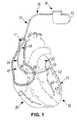
- FIG. 1is a schematic drawing of a cardiac rhythm management system including a pulse generator coupled to a lead deployed in a patient's heart, according to embodiments of the present invention.
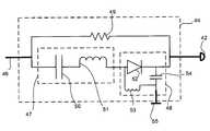
- FIG. 2is a schematic drawing of a filter circuit with a band pass filter connected in series between a lead conductor and an electrode, according to embodiments of the present invention.
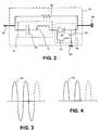
- FIG. 3is a sinusoidal voltage diagram of a therapy signal sent from a pulse generator to an electrode, according to embodiments of the present invention.
- FIG. 4is a voltage diagram of the sinusoidal voltage diagram of FIG. 3 after diode rectification, according to embodiments of the present invention.
- FIG. 1is a schematic drawing of a cardiac rhythm management system 10 including a pulse generator 12 coupled to a lead 14 deployed in a patient's heart 16 from a superior vena cava 17 .
- the pulse generator 12is typically implanted subcutaneously at an implantation location in the patient's chest or abdomen.
- the heart 16includes a right atrium 18 and a right ventricle 20 , a left atrium 22 and a left ventricle 24 , a coronary sinus ostium 26 in the right atrium 18 , a coronary sinus 28 , and various cardiac branch vessels including a great cardiac vein 30 and an exemplary branch vessel 32 .
- the lead 14may include an elongate body 34 including a proximal region 36 and a distal region 38 .
- the distal region 38has a distal end 40 including an electrode 42 , according to embodiments of the present invention.
- the lead 14includes a lead conductor which conductively connects the pulse generator 12 to the electrode 42 , according to embodiments of the present invention.
- leads 14may be deployed in coronary veins 32 through the coronary sinus 28 .
- the lead 14may alternatively include one or more sensors and/or one or more electrodes 42 , and may couple the one or more sensors with a monitor instead of and/or in addition to the pulse generator 12 .
- FIG. 2illustrates a filter circuit 44 connected in series between a lead conductor 46 (which comprises part of lead 14 ) and an electrode 42 , according to embodiments of the present invention.
- the filter circuit 44includes a band pass filter 47 and a rectifier circuit 48 , connected between the lead conductor 46 and the electrode 42 , in parallel with a resistor 49 , according to embodiments of the present invention.
- the band pass filterincludes a capacitor 50 and an inductor 51 electrically connected in series
- the rectifier circuit 48includes a diode 52 electrically connected in parallel with an inductor 53 and a capacitor 54 , according to embodiments of the present invention.
- the filter circuit 44may be used with multiple electrodes; for example, a ring electrode 55 may be electrically connected to the circuit 44 in addition to the electrode 42 , which may be a tip electrode, according to embodiments of the present invention.
- the band pass filter 47attenuates (e.g. blocks) frequencies except for a natural resonance frequency, f 0 .
- the natural resonance frequency f 0 in hertzmay be found with the following equation:
- the natural resonance frequency of the circuit 44may be determined with (EQ. 1).
- additional componentsare added between the band pass filter 47 and the electrode 42 , such as, for example, inductor 53 and capacitor 54 , the equation for calculating the natural resonance frequency of the circuit 44 changes.
- the natural resonance frequency for any given circuit 44may also be determined empirically through circuit 44 testing and/or simulation.
- the term “band pass filter”is used in its broadest sense to refer to all circuitry between the lead conductor 46 and the electrode 42 that cooperates to attenuate signals passing through the circuit 44 .
- the band pass filter 47 of FIG. 2is shown as including the capacitor 50 and the inductor 51 , the band pass filter 47 may also include the components of the rectifier circuit 48 , such that a natural resonance frequency of the band pass filter 47 is the natural resonance frequency of all such components, according to embodiments of the present invention.
- the band pass filter 47attenuates signals at frequencies other than the natural resonance frequency by blocking such signals. According to other embodiments of the present invention, the band pass filter 47 attenuates signals at frequencies other than the natural resonance frequency by weakening such signals or reducing their amplitude without completely blocking them. According to some embodiments of the present invention, the band pass filter 47 attenuates signals at frequencies closer to the natural resonance frequency to a lesser degree than signals at frequencies further from the natural resonance frequency.
- a natural resonance frequency rangeexists. Signals in the natural resonance frequency range still have enough power to adequately provide therapy through the electrode 42 after passing through the band pass filter 47 , but the natural resonance frequency range excludes frequencies at which signals are generated by an MRI system. According to such embodiments, the band pass filter 47 still substantially shields MRI signals between the lead conductor 46 and the electrode 42 , while permitting transmission of therapy signals to the electrode 42 through the band pass filter 47 by a range of signal frequencies that are not exactly at the natural resonance frequency. Based on the disclosure provided herein, one of ordinary skill in the art will recognize that selection of such a natural resonance frequency range may depend on a number of factors, including hardware selection for the filter circuit 44 and therapy requirements.
- the implantable device leads 14When electromagnetic radiation from an MRI system is picked up by the implantable device leads 14 , and more specifically by the lead conductor 46 , the energy may be transferred through the lead conductor 46 and into the electrode 42 , which is in contact with tissue, which may lead to elevated temperature at the point of contact.
- the induced voltage in the lead conductor 46may also potentially disrupt the functionality of the pulse generator 12 and/or lead electrode 42 .
- the radiofrequency energy of electromagnetic wave and lower frequency voltage induced by an MRI gradient field in the lead conductor 46can be filtered out by using the filter circuit 44 , and more specifically by using the band pass filter 47 , according to embodiments of the present invention.
- resistor 49is a high impedance resistor.
- the impedance of the resistor 49is high enough to prevent electromagnetic energy picked up by the lead conductor 46 from transferring to the surrounding tissue via the electrode 42 .
- the impedance of the resistor 49is low enough to provide a conductive path between the pulse generator 12 and a common ground to permit sensing applications which might otherwise be inhibited by the inclusion of the band pass filter 47 , at the electrode 42 , according to embodiments of the present invention.
- the pulse generator 12transmits therapy through the lead conductor 46 as a sinusoidal voltage signal 56 at the natural resonance frequency of the band pass filter 47 .
- the therapy voltage signal 56is or operates as an alternating current (AC) signal.
- the band pass filter 47permits the sinusoidal voltage signal 56 to pass through because its frequency matches or is substantially similar to the natural resonance frequency, while blocking the undesirable voltage signals created in the lead conductor 46 and/or electrode 42 by the MRI system because their frequencies do not match the natural resonance frequency.
- the rectifier circuit 48rectifies the sinusoidal voltage signal 56 to form a rectified signal 58 , as illustrated in FIG. 4 , according to embodiments of the present invention.
- the rectified signal 58is or operates as a direct current (DC) signal, according to embodiments of the present invention.
- FIG. 2depicts certain components comprising the band pass filter 47 and/or the rectifier circuit 48
- the band pass filter 47may alternatively include a second, third, or fourth order filter configuration, or components and/or configurations that filter the signal at varying frequencies and/or in different ways.
- the band pass filter 47may alternatively include a second, third, or fourth order filter configuration, or components and/or configurations that filter the signal at varying frequencies and/or in different ways.
- Various other rectifier circuitsmay also be used.
- Rectifier circuit 48may include additional components that further condition the signal in addition to rectifying it, for example.
Landscapes
- Health & Medical Sciences (AREA)
- Heart & Thoracic Surgery (AREA)
- Vascular Medicine (AREA)
- Cardiology (AREA)
- Engineering & Computer Science (AREA)
- Biomedical Technology (AREA)
- Nuclear Medicine, Radiotherapy & Molecular Imaging (AREA)
- Radiology & Medical Imaging (AREA)
- Life Sciences & Earth Sciences (AREA)
- Animal Behavior & Ethology (AREA)
- General Health & Medical Sciences (AREA)
- Public Health (AREA)
- Veterinary Medicine (AREA)
- Electrotherapy Devices (AREA)
Abstract
Description
This application claims the benefit of U.S. Provisional Patent Application Ser. No. 61/027,753, filed on Feb. 11, 2008, and entitled, “MRI SHIELDING IN ELECTRODES USING AC PACING,” which is incorporated by reference herein in its entirety for all purposes.
Embodiments of the present invention relate to medical devices and the simultaneous delivery of diagnostic and therapeutic treatments. More specifically, embodiments of the present invention relate to devices and methods for delivery of cardiovascular diagnostic or pacing therapy in a magnetic field environment.
Magnetic resonance imaging (MRI) is a non-invasive imaging method that utilizes nuclear magnetic resonance techniques to render images within a patient's body. Typically, MRI systems employ the use of a magnetic coil having a magnetic field strength of between about 0.2 to 3 Teslas. During the procedure, the body tissue is briefly exposed to RF pulses of electromagnetic energy in a plane perpendicular to the magnetic field. The resultant electromagnetic energy from these pulses can be used to image the body tissue by measuring the relaxation properties of the excited atomic nuclei in the tissue.
During imaging, the electromagnetic radiation produced by the MRI system may be picked up by implantable device leads used in implantable medical devices such as pacemakers or cardiac defibrillators. This energy may be transferred through the lead to the electrode in contact with the tissue, which may lead to elevated temperatures at the point of contact. The degree of tissue heating is typically related to factors such as the length of the lead, the conductivity or impedance of the lead, and the surface area of the lead electrodes. Exposure to a magnetic field may also induce an undesired voltage in the lead.
Accordingly, there is an ongoing need for devices and methods for shielding medical devices from magnetic fields during medical procedures such as magnetic resonance imaging (MRI).
According to embodiments of the present invention, a filter circuit electrically connected in series between the lead conductor and the electrode includes a band pass filter which attenuates signals having a frequency other than a natural resonance frequency. According to such embodiments, the pulse generator transmits therapy signals to the electrode as a sinusoidal voltage wave at the natural resonance frequency. The band pass filter permits therapy voltage signals at the natural resonance frequency to pass through to the electrode, while blocking MRI-induced voltage signals which are at frequencies different from the natural frequency, according to embodiments of the present invention. The filter circuit may also include a rectifier circuit, such as a diode, to rectify the sinusoidal voltage wave at the natural frequency into a direct current signal for the electrode.
While some embodiments are disclosed, still other embodiments of the present invention will become apparent to those skilled in the art from the following detailed description, which shows and describes illustrative embodiments of the invention. Accordingly, the drawings and detailed description are to be regarded as illustrative in nature and not restrictive.
While the invention is amenable to various modifications and alternative forms, specific embodiments have been shown by way of example in the drawings and are described in detail below. The intention, however, is not to limit the invention to the particular embodiments described. On the contrary, the invention is intended to cover all modifications, equivalents, and alternatives falling within the scope of the appended claims.
As shown inFIG. 1 , thelead 14 may include anelongate body 34 including aproximal region 36 and adistal region 38. Thedistal region 38 has adistal end 40 including anelectrode 42, according to embodiments of the present invention. Thelead 14 includes a lead conductor which conductively connects thepulse generator 12 to theelectrode 42, according to embodiments of the present invention. To facilitate left ventricular pacing epicardially via a transvenous approach, leads14 may be deployed incoronary veins 32 through thecoronary sinus 28. AlthoughFIG. 1 depicts thelead 14 as part of a cardiacrhythm management system 10 with anelectrode 42, thelead 14 may alternatively include one or more sensors and/or one ormore electrodes 42, and may couple the one or more sensors with a monitor instead of and/or in addition to thepulse generator 12.
Theband pass filter 47 attenuates (e.g. blocks) frequencies except for a natural resonance frequency, f0. The natural resonance frequency f0in hertz may be found with the following equation:
where L is the inductance of the
According to some embodiments of the present invention, theband pass filter 47 attenuates signals at frequencies other than the natural resonance frequency by blocking such signals. According to other embodiments of the present invention, theband pass filter 47 attenuates signals at frequencies other than the natural resonance frequency by weakening such signals or reducing their amplitude without completely blocking them. According to some embodiments of the present invention, theband pass filter 47 attenuates signals at frequencies closer to the natural resonance frequency to a lesser degree than signals at frequencies further from the natural resonance frequency.
According to some embodiments of the present invention, a natural resonance frequency range exists. Signals in the natural resonance frequency range still have enough power to adequately provide therapy through theelectrode 42 after passing through theband pass filter 47, but the natural resonance frequency range excludes frequencies at which signals are generated by an MRI system. According to such embodiments, theband pass filter 47 still substantially shields MRI signals between the lead conductor46 and theelectrode 42, while permitting transmission of therapy signals to theelectrode 42 through theband pass filter 47 by a range of signal frequencies that are not exactly at the natural resonance frequency. Based on the disclosure provided herein, one of ordinary skill in the art will recognize that selection of such a natural resonance frequency range may depend on a number of factors, including hardware selection for thefilter circuit 44 and therapy requirements.
When electromagnetic radiation from an MRI system is picked up by the implantable device leads14, and more specifically by the lead conductor46, the energy may be transferred through the lead conductor46 and into theelectrode 42, which is in contact with tissue, which may lead to elevated temperature at the point of contact. The induced voltage in the lead conductor46 may also potentially disrupt the functionality of thepulse generator 12 and/orlead electrode 42. However, the radiofrequency energy of electromagnetic wave and lower frequency voltage induced by an MRI gradient field in the lead conductor46 can be filtered out by using thefilter circuit 44, and more specifically by using theband pass filter 47, according to embodiments of the present invention.
In some embodiments,resistor 49 is a high impedance resistor. As an example, the impedance of theresistor 49 is high enough to prevent electromagnetic energy picked up by the lead conductor46 from transferring to the surrounding tissue via theelectrode 42. However, the impedance of theresistor 49 is low enough to provide a conductive path between thepulse generator 12 and a common ground to permit sensing applications which might otherwise be inhibited by the inclusion of theband pass filter 47, at theelectrode 42, according to embodiments of the present invention.
As illustrated inFIG. 3 , thepulse generator 12 transmits therapy through the lead conductor46 as asinusoidal voltage signal 56 at the natural resonance frequency of theband pass filter 47. According to some embodiments of the present invention, thetherapy voltage signal 56 is or operates as an alternating current (AC) signal. Theband pass filter 47 permits thesinusoidal voltage signal 56 to pass through because its frequency matches or is substantially similar to the natural resonance frequency, while blocking the undesirable voltage signals created in the lead conductor46 and/orelectrode 42 by the MRI system because their frequencies do not match the natural resonance frequency. Therectifier circuit 48 rectifies thesinusoidal voltage signal 56 to form a rectifiedsignal 58, as illustrated inFIG. 4 , according to embodiments of the present invention. The rectifiedsignal 58 is or operates as a direct current (DC) signal, according to embodiments of the present invention.
AlthoughFIG. 2 depicts certain components comprising theband pass filter 47 and/or therectifier circuit 48, one of ordinary skill in the art, based on the disclosure herein, will recognize that a variety of additional and other circuit layouts and components may be used forband pass filter 47 and/orrectifier circuit 48. For example, theband pass filter 47 may alternatively include a second, third, or fourth order filter configuration, or components and/or configurations that filter the signal at varying frequencies and/or in different ways. Various other rectifier circuits may also be used.Rectifier circuit 48 may include additional components that further condition the signal in addition to rectifying it, for example.
Various modifications and additions can be made to the exemplary embodiments discussed without departing from the scope of the present invention. For example, while the embodiments described above refer to particular features, the scope of this invention also includes embodiments having different combinations of features and embodiments that do not include all of the described features. Accordingly, the scope of the present invention is intended to embrace all such alternatives, modifications, and variations as fall within the scope of the claims, together with all equivalents thereof.
Claims (21)
1. A medical device, comprising:
a pulse generator;
an electrode configured to contact tissue in a coronary vessel;
a lead comprising a lead conductor, the lead conductor connecting the pulse generator with the electrode; and
a filter circuit electrically connected in series between the lead conductor and the electrode, the filter circuit comprising a band pass filter;
wherein the band pass filter attenuates signals having a frequency other than a natural resonance frequency, and wherein the pulse generator transmits signals as a sinusoidal voltage wave at about the natural resonance frequency; and
wherein the filter circuit further comprises a rectifier circuit, and wherein the rectifier curcuit rectifies the sinusoidal voltage wave before the rectified sinusoidal voltage wave passes to the electrodes.
2. The medical device ofclaim 1 , wherein the rectifier circuit comprises a diode electrically connected in parallel with an inductor and a capacitor.
3. The medical device ofclaim 1 , wherein the sinusoidal voltage wave operates as an alternating current signal, and wherein the rectified sinusoidal voltage wave operates as a direct current signal.
4. The medical device ofclaim 1 , wherein the filter circuit further comprises a resistor electrically connected in parallel with the band pass filter.
5. The medical device ofclaim 4 , wherein a resistance of the resistor shields electromagnetic energy received by the lead conductor from the electrode and creates a link between the lead conductor and the electrode to permit use of the electrode for sensing applications.
6. The medical device ofclaim 5 , wherein the band pass filter comprises a capacitor and an inductor.
7. The medical device ofclaim 1 , wherein the band pass filter comprises a capacitor and an inductor.
8. A medical device, comprising:
an electrode configured to contact tissue in a coronary vessel;
a lead comprising a lead conductor, the lead conductor electrically connecting to the electrode and configured to electrically connect to a pulse generator; and
a filter circuit electrically connected in series between the lead conductor and the electrode, the filter circuit comprising a band pass filter;
wherein the band pass filter attenuates signals having a frequency other than a natural resonance frequency, and wherein the lead conductor receives transmissions of signals from the pulse generator as a sinusoidal voltage wave at about the natural resonance frequency; and
wherein the filter circuit comprises a rectifier circuit, and wherein the rectifier circuit rectifies the sinusoidal voltage wave before the rectified sinusoidal voltage wave passes to the electrode.
9. The medical device ofclaim 8 , wherein the rectifier circuit further comprises a diode, and wherein the diode rectifies the sinusoidal voltage wave before the rectified sinusoidal voltage wave passes to the electrode.
10. The medical device ofclaim 9 , wherein the sinusoidal voltage wave operates as an alternating current signal, and wherein the rectified sinusoidal voltage wave operates as a direct current signal.
11. The medical device ofclaim 8 , wherein the filter circuit further comprises a resistor electrically connected in parallel with the band pass filter.
12. The medical device ofclaim 11 , wherein a resistance of the resistor shields electromagnetic energy received by the lead conductor from the electrode and creates a link between the lead conductor and the electrode to permit use of the electrode for sensing applications.
13. The medical device ofclaim 8 , wherein the band pass filter comprises a capacitor and an inductor.
14. A medical device, comprising:
a pulse generator;
an electrode configured to contact tissue in a coronary vessel;
a lead comprising a lead conductor, the lead conductor electrically connecting the pulse generator with the electrode; and
a filter circuit electrically connected in series between the lead conductor and the electrode, the filter circuit comprising a band pass filter;
wherein the pulse generator is configured to transmit a signal to the electrode through the band pass filter at a frequency within a natural resonance frequency range of the band pass filter, and wherein the band pass filter is configured to shield the electrode from signals with frequencies outside of the natural resonance frequency range; and
wherein the filter circuit further comprises a rectifier circuit, and wherein the rectifier circuit rectifies the signal from the pulse generator before the rectified signal passes to the electrode.
15. The medical device ofclaim 14 , wherein the pulse generator is configured to transmit the signal to the electrode as a sinusoidal voltage wave.
16. The medical device ofclaim 15 , wherein the rectifier circuit rectifies the sinusoidal voltage wave before the rectified sinusoidal voltage wave passes to the electrode.
17. The medical device ofclaim 16 , wherein the rectifier circuit comprises a diode.
18. The medical device ofclaim 16 , wherein the rectifier circuit comprises a diode electrically connected in parallel with an inductor and a capacitor.
19. The medical device ofclaim 14 , wherein the filter circuit further comprises a resistor electrically connected in parallel with the band pass filter.
20. The medical device ofclaim 19 , wherein a resistance of the resistor shields electromagnetic energy received by the lead conductor and creates a link between the lead conductor and the electrode to permit use of the electrode for sensing applications.
21. The medical device ofclaim 14 , wherein the band pass filter comprises a capacitor and an inductor.
Priority Applications (1)
| Application Number | Priority Date | Filing Date | Title |
|---|---|---|---|
| US12/367,457US8255055B2 (en) | 2008-02-11 | 2009-02-06 | MRI shielding in electrodes using AC pacing |
Applications Claiming Priority (2)
| Application Number | Priority Date | Filing Date | Title |
|---|---|---|---|
| US2775308P | 2008-02-11 | 2008-02-11 | |
| US12/367,457US8255055B2 (en) | 2008-02-11 | 2009-02-06 | MRI shielding in electrodes using AC pacing |
Publications (2)
| Publication Number | Publication Date |
|---|---|
| US20090204171A1 US20090204171A1 (en) | 2009-08-13 |
| US8255055B2true US8255055B2 (en) | 2012-08-28 |
Family
ID=40939556
Family Applications (1)
| Application Number | Title | Priority Date | Filing Date |
|---|---|---|---|
| US12/367,457Expired - Fee RelatedUS8255055B2 (en) | 2008-02-11 | 2009-02-06 | MRI shielding in electrodes using AC pacing |
Country Status (1)
| Country | Link |
|---|---|
| US (1) | US8255055B2 (en) |
Cited By (12)
| Publication number | Priority date | Publication date | Assignee | Title |
|---|---|---|---|---|
| US20100106215A1 (en)* | 2008-10-23 | 2010-04-29 | Stubbs Scott R | Systems and methods to detect implantable medical device configuaration changes affecting mri conditional safety |
| US8798767B2 (en) | 2009-12-31 | 2014-08-05 | Cardiac Pacemakers, Inc. | MRI conditionally safe lead with multi-layer conductor |
| US8825179B2 (en) | 2012-04-20 | 2014-09-02 | Cardiac Pacemakers, Inc. | Implantable medical device lead including a unifilar coiled cable |
| US8825181B2 (en) | 2010-08-30 | 2014-09-02 | Cardiac Pacemakers, Inc. | Lead conductor with pitch and torque control for MRI conditionally safe use |
| US8954168B2 (en) | 2012-06-01 | 2015-02-10 | Cardiac Pacemakers, Inc. | Implantable device lead including a distal electrode assembly with a coiled component |
| US8958889B2 (en) | 2012-08-31 | 2015-02-17 | Cardiac Pacemakers, Inc. | MRI compatible lead coil |
| US8983623B2 (en) | 2012-10-18 | 2015-03-17 | Cardiac Pacemakers, Inc. | Inductive element for providing MRI compatibility in an implantable medical device lead |
| US9050457B2 (en) | 2009-12-31 | 2015-06-09 | Cardiac Pacemakers, Inc. | MRI conditionally safe lead with low-profile conductor for longitudinal expansion |
| US9084883B2 (en) | 2009-03-12 | 2015-07-21 | Cardiac Pacemakers, Inc. | Thin profile conductor assembly for medical device leads |
| US9254380B2 (en) | 2009-10-19 | 2016-02-09 | Cardiac Pacemakers, Inc. | MRI compatible tachycardia lead |
| US9504821B2 (en) | 2014-02-26 | 2016-11-29 | Cardiac Pacemakers, Inc. | Construction of an MRI-safe tachycardia lead |
| US9750944B2 (en) | 2009-12-30 | 2017-09-05 | Cardiac Pacemakers, Inc. | MRI-conditionally safe medical device lead |
Families Citing this family (8)
| Publication number | Priority date | Publication date | Assignee | Title |
|---|---|---|---|---|
| US9008792B2 (en)* | 2009-08-20 | 2015-04-14 | Med-El Elektromedizinische Geraete Gmbh | MRI-safe implant electronics |
| WO2011043898A2 (en)* | 2009-10-09 | 2011-04-14 | Cardiac Pacemakers, Inc. | Mri compatible medical device lead including transmission line notch filters |
| US8406895B2 (en)* | 2009-12-30 | 2013-03-26 | Cardiac Pacemakers, Inc. | Implantable electrical lead including a cooling assembly to dissipate MRI induced electrode heat |
| US8306630B2 (en)* | 2009-12-30 | 2012-11-06 | Cardiac Pacemakers, Inc. | Apparatus to selectively increase medical device lead inner conductor inductance |
| US8612021B2 (en) | 2011-02-10 | 2013-12-17 | Medtronic, Inc. | Magnetic resonance imaging compatible medical electrical lead and method of making the same |
| EP2537553B1 (en) | 2011-06-21 | 2013-08-28 | Sorin CRM SAS | Probe for implantable cardiac prosthesis, comprising a built-in means for protection against the effects of MRI fields |
| CN105473093B (en) | 2013-08-22 | 2019-02-05 | 波士顿科学国际有限公司 | Flexible circuit with improved adhesion to renal neuromodulation balloon |
| US11877783B2 (en)* | 2018-01-29 | 2024-01-23 | Medtronic, Inc. | Cardiac surgical instrument and connector with built-in electrogram (EGM) filtering circuitry |
Citations (71)
| Publication number | Priority date | Publication date | Assignee | Title |
|---|---|---|---|---|
| US5003975A (en) | 1988-04-19 | 1991-04-02 | Siemens-Pacesetter, Inc. | Automatic electrode configuration of an implantable pacemaker |
| US5201865A (en) | 1991-10-28 | 1993-04-13 | Medtronic, Inc. | Medical lead impedance measurement system |
| US5370666A (en) | 1992-06-05 | 1994-12-06 | Siemens-Elema Ab | Pacemaker with power-consuming component inhibited during storage |
| US5476485A (en) | 1993-09-21 | 1995-12-19 | Pacesetter, Inc. | Automatic implantable pulse generator |
| US5534018A (en) | 1994-11-30 | 1996-07-09 | Medtronic, Inc. | Automatic lead recognition for implantable medical device |
| US5549646A (en) | 1994-12-06 | 1996-08-27 | Pacesetter, Inc. | Periodic electrical lead intergrity testing system and method for implantable cardiac stimulating devices |
| US5727552A (en) | 1996-01-11 | 1998-03-17 | Medtronic, Inc. | Catheter and electrical lead location system |
| US5727553A (en) | 1996-03-25 | 1998-03-17 | Saad; Saad A. | Catheter with integral electromagnetic location identification device |
| US5755742A (en) | 1996-11-05 | 1998-05-26 | Medtronic, Inc. | Cardioversion/defibrillation lead impedance measurement system |
| US5766227A (en) | 1997-03-04 | 1998-06-16 | Nappholz; Tibor A. | EMI detection in an implantable pacemaker and the like |
| US5800496A (en) | 1996-06-24 | 1998-09-01 | Medtronic, Inc. | Medical electrical lead having a crush resistant lead body |
| US5817136A (en) | 1997-05-02 | 1998-10-06 | Pacesetter, Inc. | Rate-responsive pacemaker with minute volume determination and EMI protection |
| US5861013A (en)* | 1997-04-29 | 1999-01-19 | Medtronic Inc. | Peak tracking capture detection circuit and method |
| US5891179A (en) | 1997-11-20 | 1999-04-06 | Paceseter, Inc. | Method and apparatus for monitoring and displaying lead impedance in real-time for an implantable medical device |
| US6016447A (en) | 1998-10-27 | 2000-01-18 | Medtronic, Inc. | Pacemaker implant recognition |
| US6101417A (en) | 1998-05-12 | 2000-08-08 | Pacesetter, Inc. | Implantable electrical device incorporating a magnetoresistive magnetic field sensor |
| US6317633B1 (en) | 1999-01-19 | 2001-11-13 | Medtronic, Inc. | Implantable lead functional status monitor and method |
| US20030083726A1 (en)* | 2001-10-31 | 2003-05-01 | Medtronic, Inc. | Method and apparatus for shunting induced currents in an electrical lead |
| US20030144718A1 (en) | 2002-01-29 | 2003-07-31 | Zeijlemaker Volkert A. | Method and apparatus for shielding coating for MRI resistant electrode systems |
| US20030144721A1 (en) | 2002-01-29 | 2003-07-31 | Villaseca Eduardo H. | Conditioning of coupled electromagnetic signals on a lead |
| US20030140931A1 (en) | 2002-01-29 | 2003-07-31 | Zeijlemaker Volkert A. | Medical implantable system for reducing magnetic resonance effects |
| US20030144705A1 (en) | 2002-01-29 | 2003-07-31 | Medtronic, Inc. | Methods and apparatus for controlling a pacing system in the presence of EMI |
| US20030144719A1 (en) | 2002-01-29 | 2003-07-31 | Zeijlemaker Volkert A. | Method and apparatus for shielding wire for MRI resistant electrode systems |
| US20030204217A1 (en) | 2002-04-25 | 2003-10-30 | Wilson Greatbatch | MRI-safe cardiac stimulation device |
| US20040064161A1 (en) | 2002-09-30 | 2004-04-01 | Gunderson Bruce D. | Method and apparatus for identifying lead-related conditions using lead impedance measurements |
| US6721600B2 (en) | 2000-01-19 | 2004-04-13 | Medtronic, Inc. | Implantable lead functional status monitor and method |
| US20050113676A1 (en) | 2003-04-02 | 2005-05-26 | Biophan Technologies, Inc. | Device and method for preventing magnetic-resonance imaging induced damage |
| US6923804B2 (en)* | 2001-07-12 | 2005-08-02 | Neothermia Corporation | Electrosurgical generator |
| US20050197677A1 (en) | 2004-02-12 | 2005-09-08 | Stevenson Robert A. | Apparatus and process for reducing the susceptability of active implantable medical devices to medical procedures such as magnetic resonance imaging |
| US6949929B2 (en) | 2003-06-24 | 2005-09-27 | Biophan Technologies, Inc. | Magnetic resonance imaging interference immune device |
| US20050222659A1 (en) | 2004-03-30 | 2005-10-06 | Medtronic, Inc. | Lead electrode for use in an MRI-safe implantable medical device |
| US20050222657A1 (en) | 2004-03-30 | 2005-10-06 | Wahlstrand Carl D | MRI-safe implantable lead |
| US20050222656A1 (en) | 2004-03-30 | 2005-10-06 | Wahlstrand Carl D | MRI-safe implantable medical device |
| US20050222658A1 (en) | 2004-03-30 | 2005-10-06 | Medtronic, Inc. | Lead electrode for use in an MRI-safe implantable medical device |
| US20060030774A1 (en) | 2003-06-24 | 2006-02-09 | Biophan Technologies, Inc. | Magnetic resonance imaging interference immune device |
| US6999818B2 (en) | 2003-05-23 | 2006-02-14 | Greatbatch-Sierra, Inc. | Inductor capacitor EMI filter for human implant applications |
| US20060041294A1 (en) | 2004-08-20 | 2006-02-23 | Biophan Technologies, Inc. | Magnetic resonance imaging interference immune device |
| US7047075B2 (en) | 2003-04-17 | 2006-05-16 | Cardiac Pacemakers, Inc. | Apparatus for actively monitoring device for lead fixation in implantable tissue stimulators |
| US20060118758A1 (en) | 2004-09-15 | 2006-06-08 | Xingwu Wang | Material to enable magnetic resonance imaging of implantable medical devices |
| US7113827B2 (en) | 2003-01-17 | 2006-09-26 | Ela Medical S.A.S. | Determining the presence and type of probe associated with an active implantable medical device, in particular a cardiac pacemaker |
| US20060247747A1 (en) | 2005-04-29 | 2006-11-02 | Medtronic, Inc. | Lead electrode for use in an MRI-safe implantable medical device |
| US20060247748A1 (en) | 2005-04-29 | 2006-11-02 | Medtronic, Inc. | Lead electrode for use in an MRI-safe implantable medical device |
| US20060252314A1 (en) | 2005-05-04 | 2006-11-09 | Ergin Atalar | Electrical lead for an electronic device such as an implantable device |
| US7135978B2 (en) | 2001-09-14 | 2006-11-14 | Calypso Medical Technologies, Inc. | Miniature resonating marker assembly |
| US7138582B2 (en) | 2003-06-24 | 2006-11-21 | Medtronic, Inc. | Medical electrical lead conductor formed from modified MP35N alloy |
| US20060271138A1 (en) | 2005-05-27 | 2006-11-30 | Biophan Technologies, Inc. | Electromagnetic interference immune pacing/defibrillation lead |
| US20070010702A1 (en) | 2003-04-08 | 2007-01-11 | Xingwu Wang | Medical device with low magnetic susceptibility |
| US20070027532A1 (en) | 2003-12-22 | 2007-02-01 | Xingwu Wang | Medical device |
| US7174220B1 (en) | 2004-03-16 | 2007-02-06 | Pacesetter, Inc. | Construction of a medical electrical lead |
| US7174219B2 (en) | 2004-03-30 | 2007-02-06 | Medtronic, Inc. | Lead electrode for use in an MRI-safe implantable medical device |
| US7239916B2 (en) | 2001-07-17 | 2007-07-03 | Medtronic, Inc. | Method and apparatus for automatic implantable medical lead recognition and configuration |
| US20070179582A1 (en) | 2006-01-31 | 2007-08-02 | Marshall Mark T | Polymer reinforced coil conductor for torque transmission |
| US20070179577A1 (en) | 2006-01-31 | 2007-08-02 | Marshall Mark T | Medical electrical lead having improved inductance |
| US20070191914A1 (en) | 2006-02-16 | 2007-08-16 | Stessman Nicholas J | Mri detector for implantable medical device |
| US7289851B2 (en) | 2003-12-04 | 2007-10-30 | Medtronic, Inc. | Method and apparatus for identifying lead-related conditions using impedance trends and oversensing criteria |
| US20080033497A1 (en) | 2005-11-04 | 2008-02-07 | Cherik Bulkes | Mri compatible implanted electronic medical device and lead |
| US20080051854A1 (en) | 2005-11-04 | 2008-02-28 | Cherik Bulkes | Mri compatible implanted electronic medical device with power and data communication capability |
| US7369893B2 (en) | 2004-12-01 | 2008-05-06 | Medtronic, Inc. | Method and apparatus for identifying lead-related conditions using prediction and detection criteria |
| US20080132985A1 (en) | 2006-11-30 | 2008-06-05 | Cardiac Pacemakers, Inc. | Rf rejecting lead |
| US20080154348A1 (en)* | 2006-12-18 | 2008-06-26 | Ergin Atalar | Mri compatible implantable devices |
| US20080208290A1 (en) | 2007-01-18 | 2008-08-28 | Medtronic, Inc. | Bi-directional connector assembly for an implantable medical device |
| US20090005825A1 (en) | 2007-06-27 | 2009-01-01 | Medtronic, Inc. | Mri-safe defibrillator electrodes |
| US20090024180A1 (en) | 2006-01-13 | 2009-01-22 | Universitat Duisburg-Essen | Stimulation system, in particular a cardiac pacemaker |
| US20090149920A1 (en) | 2007-12-06 | 2009-06-11 | Yingbo Li | Leads with high surface resistance |
| US20090149933A1 (en) | 2007-12-06 | 2009-06-11 | Cardiac Pacemakers, Inc. | Implantable lead having a variable coil conductor pitch |
| US20090210022A1 (en) | 2006-05-16 | 2009-08-20 | Koninklijke Philips Electronics, N.V. | Simplified biphasic defibrillator circuit with make-only switching |
| US20100106215A1 (en) | 2008-10-23 | 2010-04-29 | Stubbs Scott R | Systems and methods to detect implantable medical device configuaration changes affecting mri conditional safety |
| WO2010078552A1 (en) | 2009-01-05 | 2010-07-08 | Kenergy, Inc. | Mri compatible electrical lead for an implantable electronic medical device |
| US20110087302A1 (en) | 2009-10-09 | 2011-04-14 | Masoud Ameri | Mri compatible medical device lead including transmission line notch filters |
| EP1852810B1 (en) | 2006-05-05 | 2011-05-25 | Quality Electro Dynamics, LLC. | IC tags/RFID tags for magnetic resonance imaging applications |
| US20110160816A1 (en) | 2009-12-30 | 2011-06-30 | Stubbs Scott R | Apparatus to selectively increase medical device lead inner conductor inductance |
Family Cites Families (1)
| Publication number | Priority date | Publication date | Assignee | Title |
|---|---|---|---|---|
| JP4848746B2 (en)* | 2005-11-28 | 2011-12-28 | ブラザー工業株式会社 | Discharge timing determination method |
- 2009
- 2009-02-06USUS12/367,457patent/US8255055B2/ennot_activeExpired - Fee Related
Patent Citations (80)
| Publication number | Priority date | Publication date | Assignee | Title |
|---|---|---|---|---|
| US5003975A (en) | 1988-04-19 | 1991-04-02 | Siemens-Pacesetter, Inc. | Automatic electrode configuration of an implantable pacemaker |
| US5201865A (en) | 1991-10-28 | 1993-04-13 | Medtronic, Inc. | Medical lead impedance measurement system |
| US5370666A (en) | 1992-06-05 | 1994-12-06 | Siemens-Elema Ab | Pacemaker with power-consuming component inhibited during storage |
| US5476485A (en) | 1993-09-21 | 1995-12-19 | Pacesetter, Inc. | Automatic implantable pulse generator |
| US5534018A (en) | 1994-11-30 | 1996-07-09 | Medtronic, Inc. | Automatic lead recognition for implantable medical device |
| US5549646A (en) | 1994-12-06 | 1996-08-27 | Pacesetter, Inc. | Periodic electrical lead intergrity testing system and method for implantable cardiac stimulating devices |
| US5727552A (en) | 1996-01-11 | 1998-03-17 | Medtronic, Inc. | Catheter and electrical lead location system |
| US5727553A (en) | 1996-03-25 | 1998-03-17 | Saad; Saad A. | Catheter with integral electromagnetic location identification device |
| US5800496A (en) | 1996-06-24 | 1998-09-01 | Medtronic, Inc. | Medical electrical lead having a crush resistant lead body |
| US5755742A (en) | 1996-11-05 | 1998-05-26 | Medtronic, Inc. | Cardioversion/defibrillation lead impedance measurement system |
| US5766227A (en) | 1997-03-04 | 1998-06-16 | Nappholz; Tibor A. | EMI detection in an implantable pacemaker and the like |
| US5861013A (en)* | 1997-04-29 | 1999-01-19 | Medtronic Inc. | Peak tracking capture detection circuit and method |
| US5817136A (en) | 1997-05-02 | 1998-10-06 | Pacesetter, Inc. | Rate-responsive pacemaker with minute volume determination and EMI protection |
| US5891179A (en) | 1997-11-20 | 1999-04-06 | Paceseter, Inc. | Method and apparatus for monitoring and displaying lead impedance in real-time for an implantable medical device |
| US6101417A (en) | 1998-05-12 | 2000-08-08 | Pacesetter, Inc. | Implantable electrical device incorporating a magnetoresistive magnetic field sensor |
| US6016447A (en) | 1998-10-27 | 2000-01-18 | Medtronic, Inc. | Pacemaker implant recognition |
| US6317633B1 (en) | 1999-01-19 | 2001-11-13 | Medtronic, Inc. | Implantable lead functional status monitor and method |
| US6721600B2 (en) | 2000-01-19 | 2004-04-13 | Medtronic, Inc. | Implantable lead functional status monitor and method |
| US6923804B2 (en)* | 2001-07-12 | 2005-08-02 | Neothermia Corporation | Electrosurgical generator |
| US7239916B2 (en) | 2001-07-17 | 2007-07-03 | Medtronic, Inc. | Method and apparatus for automatic implantable medical lead recognition and configuration |
| US7135978B2 (en) | 2001-09-14 | 2006-11-14 | Calypso Medical Technologies, Inc. | Miniature resonating marker assembly |
| US7535363B2 (en) | 2001-09-14 | 2009-05-19 | Calypso Medical Technologies, Inc. | Miniature resonating marker assembly |
| US20030083726A1 (en)* | 2001-10-31 | 2003-05-01 | Medtronic, Inc. | Method and apparatus for shunting induced currents in an electrical lead |
| US20030144718A1 (en) | 2002-01-29 | 2003-07-31 | Zeijlemaker Volkert A. | Method and apparatus for shielding coating for MRI resistant electrode systems |
| US20030144719A1 (en) | 2002-01-29 | 2003-07-31 | Zeijlemaker Volkert A. | Method and apparatus for shielding wire for MRI resistant electrode systems |
| US7013180B2 (en) | 2002-01-29 | 2006-03-14 | Medtronic, Inc. | Conditioning of coupled electromagnetic signals on a lead |
| US20030144705A1 (en) | 2002-01-29 | 2003-07-31 | Medtronic, Inc. | Methods and apparatus for controlling a pacing system in the presence of EMI |
| US20030144720A1 (en) | 2002-01-29 | 2003-07-31 | Villaseca Eduardo H. | Electromagnetic trap for a lead |
| US20030140931A1 (en) | 2002-01-29 | 2003-07-31 | Zeijlemaker Volkert A. | Medical implantable system for reducing magnetic resonance effects |
| US7050855B2 (en) | 2002-01-29 | 2006-05-23 | Medtronic, Inc. | Medical implantable system for reducing magnetic resonance effects |
| US20030144721A1 (en) | 2002-01-29 | 2003-07-31 | Villaseca Eduardo H. | Conditioning of coupled electromagnetic signals on a lead |
| US20030204217A1 (en) | 2002-04-25 | 2003-10-30 | Wilson Greatbatch | MRI-safe cardiac stimulation device |
| US20040064161A1 (en) | 2002-09-30 | 2004-04-01 | Gunderson Bruce D. | Method and apparatus for identifying lead-related conditions using lead impedance measurements |
| US7047083B2 (en) | 2002-09-30 | 2006-05-16 | Medtronic, Inc. | Method and apparatus for identifying lead-related conditions using lead impedance measurements |
| US7113827B2 (en) | 2003-01-17 | 2006-09-26 | Ela Medical S.A.S. | Determining the presence and type of probe associated with an active implantable medical device, in particular a cardiac pacemaker |
| US20050113676A1 (en) | 2003-04-02 | 2005-05-26 | Biophan Technologies, Inc. | Device and method for preventing magnetic-resonance imaging induced damage |
| US20050113876A1 (en) | 2003-04-02 | 2005-05-26 | Biophan Technologies, Inc. | Device and method for preventing magnetic-resonance imaging induced damage |
| US20050113873A1 (en) | 2003-04-02 | 2005-05-26 | Biophan Technologies, Inc. | Device and method for preventing magnetic-resonance imaging induced damage |
| US20070010702A1 (en) | 2003-04-08 | 2007-01-11 | Xingwu Wang | Medical device with low magnetic susceptibility |
| US7047075B2 (en) | 2003-04-17 | 2006-05-16 | Cardiac Pacemakers, Inc. | Apparatus for actively monitoring device for lead fixation in implantable tissue stimulators |
| US6999818B2 (en) | 2003-05-23 | 2006-02-14 | Greatbatch-Sierra, Inc. | Inductor capacitor EMI filter for human implant applications |
| US7138582B2 (en) | 2003-06-24 | 2006-11-21 | Medtronic, Inc. | Medical electrical lead conductor formed from modified MP35N alloy |
| US20060030774A1 (en) | 2003-06-24 | 2006-02-09 | Biophan Technologies, Inc. | Magnetic resonance imaging interference immune device |
| US7388378B2 (en) | 2003-06-24 | 2008-06-17 | Medtronic, Inc. | Magnetic resonance imaging interference immune device |
| US6949929B2 (en) | 2003-06-24 | 2005-09-27 | Biophan Technologies, Inc. | Magnetic resonance imaging interference immune device |
| US7123013B2 (en) | 2003-06-24 | 2006-10-17 | Biophan Technologies, Inc. | Magnetic resonance imaging interference immune device |
| US7289851B2 (en) | 2003-12-04 | 2007-10-30 | Medtronic, Inc. | Method and apparatus for identifying lead-related conditions using impedance trends and oversensing criteria |
| US20070027532A1 (en) | 2003-12-22 | 2007-02-01 | Xingwu Wang | Medical device |
| US20050197677A1 (en) | 2004-02-12 | 2005-09-08 | Stevenson Robert A. | Apparatus and process for reducing the susceptability of active implantable medical devices to medical procedures such as magnetic resonance imaging |
| US7174220B1 (en) | 2004-03-16 | 2007-02-06 | Pacesetter, Inc. | Construction of a medical electrical lead |
| US20050222656A1 (en) | 2004-03-30 | 2005-10-06 | Wahlstrand Carl D | MRI-safe implantable medical device |
| US20050222657A1 (en) | 2004-03-30 | 2005-10-06 | Wahlstrand Carl D | MRI-safe implantable lead |
| US20050222658A1 (en) | 2004-03-30 | 2005-10-06 | Medtronic, Inc. | Lead electrode for use in an MRI-safe implantable medical device |
| US20050222659A1 (en) | 2004-03-30 | 2005-10-06 | Medtronic, Inc. | Lead electrode for use in an MRI-safe implantable medical device |
| US7174219B2 (en) | 2004-03-30 | 2007-02-06 | Medtronic, Inc. | Lead electrode for use in an MRI-safe implantable medical device |
| US20060041294A1 (en) | 2004-08-20 | 2006-02-23 | Biophan Technologies, Inc. | Magnetic resonance imaging interference immune device |
| US20060118758A1 (en) | 2004-09-15 | 2006-06-08 | Xingwu Wang | Material to enable magnetic resonance imaging of implantable medical devices |
| US7369893B2 (en) | 2004-12-01 | 2008-05-06 | Medtronic, Inc. | Method and apparatus for identifying lead-related conditions using prediction and detection criteria |
| US20060247747A1 (en) | 2005-04-29 | 2006-11-02 | Medtronic, Inc. | Lead electrode for use in an MRI-safe implantable medical device |
| US20060247748A1 (en) | 2005-04-29 | 2006-11-02 | Medtronic, Inc. | Lead electrode for use in an MRI-safe implantable medical device |
| US20060252314A1 (en) | 2005-05-04 | 2006-11-09 | Ergin Atalar | Electrical lead for an electronic device such as an implantable device |
| US20060271138A1 (en) | 2005-05-27 | 2006-11-30 | Biophan Technologies, Inc. | Electromagnetic interference immune pacing/defibrillation lead |
| US20080033497A1 (en) | 2005-11-04 | 2008-02-07 | Cherik Bulkes | Mri compatible implanted electronic medical device and lead |
| US20080051854A1 (en) | 2005-11-04 | 2008-02-28 | Cherik Bulkes | Mri compatible implanted electronic medical device with power and data communication capability |
| US20090024180A1 (en) | 2006-01-13 | 2009-01-22 | Universitat Duisburg-Essen | Stimulation system, in particular a cardiac pacemaker |
| US20070179577A1 (en) | 2006-01-31 | 2007-08-02 | Marshall Mark T | Medical electrical lead having improved inductance |
| US20070179582A1 (en) | 2006-01-31 | 2007-08-02 | Marshall Mark T | Polymer reinforced coil conductor for torque transmission |
| US20070191914A1 (en) | 2006-02-16 | 2007-08-16 | Stessman Nicholas J | Mri detector for implantable medical device |
| EP1852810B1 (en) | 2006-05-05 | 2011-05-25 | Quality Electro Dynamics, LLC. | IC tags/RFID tags for magnetic resonance imaging applications |
| US20090210022A1 (en) | 2006-05-16 | 2009-08-20 | Koninklijke Philips Electronics, N.V. | Simplified biphasic defibrillator circuit with make-only switching |
| US20080132985A1 (en) | 2006-11-30 | 2008-06-05 | Cardiac Pacemakers, Inc. | Rf rejecting lead |
| US20080154348A1 (en)* | 2006-12-18 | 2008-06-26 | Ergin Atalar | Mri compatible implantable devices |
| US20080208290A1 (en) | 2007-01-18 | 2008-08-28 | Medtronic, Inc. | Bi-directional connector assembly for an implantable medical device |
| US20090005825A1 (en) | 2007-06-27 | 2009-01-01 | Medtronic, Inc. | Mri-safe defibrillator electrodes |
| US20090149920A1 (en) | 2007-12-06 | 2009-06-11 | Yingbo Li | Leads with high surface resistance |
| US20090149933A1 (en) | 2007-12-06 | 2009-06-11 | Cardiac Pacemakers, Inc. | Implantable lead having a variable coil conductor pitch |
| US20100106215A1 (en) | 2008-10-23 | 2010-04-29 | Stubbs Scott R | Systems and methods to detect implantable medical device configuaration changes affecting mri conditional safety |
| WO2010078552A1 (en) | 2009-01-05 | 2010-07-08 | Kenergy, Inc. | Mri compatible electrical lead for an implantable electronic medical device |
| US20110087302A1 (en) | 2009-10-09 | 2011-04-14 | Masoud Ameri | Mri compatible medical device lead including transmission line notch filters |
| US20110160816A1 (en) | 2009-12-30 | 2011-06-30 | Stubbs Scott R | Apparatus to selectively increase medical device lead inner conductor inductance |
Non-Patent Citations (5)
| Title |
|---|
| Basso, Christophe, "SPICE Model Simulates Spark-Gap Arrestor", Electronics Design, Strategy, and News (EDN), Jul. 3, 1997, 4 pages. |
| File History for U.S. Appl. No. 11/015,807, filed Dec. 17, 2004. |
| International Search Report and Written Opinion issued in PCT/US2009/056843, mailed Dec. 29, 2009, 13 pages. |
| International Search Report and Written Opinion issued in PCT/US2010/048620, mailed Apr. 5, 2011, 10 pagaes. |
| Partial International Search Report issued in PCT/US2011/052541, mailed Dec. 6, 2011, 4 pages. |
Cited By (16)
| Publication number | Priority date | Publication date | Assignee | Title |
|---|---|---|---|---|
| US20100106215A1 (en)* | 2008-10-23 | 2010-04-29 | Stubbs Scott R | Systems and methods to detect implantable medical device configuaration changes affecting mri conditional safety |
| US9084883B2 (en) | 2009-03-12 | 2015-07-21 | Cardiac Pacemakers, Inc. | Thin profile conductor assembly for medical device leads |
| US9254380B2 (en) | 2009-10-19 | 2016-02-09 | Cardiac Pacemakers, Inc. | MRI compatible tachycardia lead |
| US9750944B2 (en) | 2009-12-30 | 2017-09-05 | Cardiac Pacemakers, Inc. | MRI-conditionally safe medical device lead |
| US9199077B2 (en) | 2009-12-31 | 2015-12-01 | Cardiac Pacemakers, Inc. | MRI conditionally safe lead with multi-layer conductor |
| US8798767B2 (en) | 2009-12-31 | 2014-08-05 | Cardiac Pacemakers, Inc. | MRI conditionally safe lead with multi-layer conductor |
| US9050457B2 (en) | 2009-12-31 | 2015-06-09 | Cardiac Pacemakers, Inc. | MRI conditionally safe lead with low-profile conductor for longitudinal expansion |
| US8825181B2 (en) | 2010-08-30 | 2014-09-02 | Cardiac Pacemakers, Inc. | Lead conductor with pitch and torque control for MRI conditionally safe use |
| US8825179B2 (en) | 2012-04-20 | 2014-09-02 | Cardiac Pacemakers, Inc. | Implantable medical device lead including a unifilar coiled cable |
| US8954168B2 (en) | 2012-06-01 | 2015-02-10 | Cardiac Pacemakers, Inc. | Implantable device lead including a distal electrode assembly with a coiled component |
| US9333344B2 (en) | 2012-06-01 | 2016-05-10 | Cardiac Pacemakers, Inc. | Implantable device lead including a distal electrode assembly with a coiled component |
| US8958889B2 (en) | 2012-08-31 | 2015-02-17 | Cardiac Pacemakers, Inc. | MRI compatible lead coil |
| US8983623B2 (en) | 2012-10-18 | 2015-03-17 | Cardiac Pacemakers, Inc. | Inductive element for providing MRI compatibility in an implantable medical device lead |
| US9504822B2 (en) | 2012-10-18 | 2016-11-29 | Cardiac Pacemakers, Inc. | Inductive element for providing MRI compatibility in an implantable medical device lead |
| US9504821B2 (en) | 2014-02-26 | 2016-11-29 | Cardiac Pacemakers, Inc. | Construction of an MRI-safe tachycardia lead |
| US9682231B2 (en) | 2014-02-26 | 2017-06-20 | Cardiac Pacemakers, Inc. | Construction of an MRI-safe tachycardia lead |
Also Published As
| Publication number | Publication date |
|---|---|
| US20090204171A1 (en) | 2009-08-13 |
Similar Documents
| Publication | Publication Date | Title |
|---|---|---|
| US8255055B2 (en) | MRI shielding in electrodes using AC pacing | |
| US8989870B2 (en) | Tuned energy balanced system for minimizing heating and/or to provide EMI protection of implanted leads in a high power electromagnetic field environment | |
| US9393405B2 (en) | Wireless tissue electrostimulation | |
| US8447414B2 (en) | Switched safety protection circuit for an AIMD system during exposure to high power electromagnetic fields | |
| US7751903B2 (en) | Frequency selective passive component networks for implantable leads of active implantable medical devices utilizing an energy dissipating surface | |
| US8145324B1 (en) | Implantable lead bandstop filter employing an inductive coil with parasitic capacitance to enhance MRI compatibility of active medical devices | |
| US8224462B2 (en) | Medical lead system utilizing electromagnetic bandstop filters | |
| EP2067501A2 (en) | Resonance circuit for implantable devices and leads | |
| US20130253297A1 (en) | Switched diverter circuits for minimizing heating of an implanted lead and/or providing emi protection in a high power electromagnetic field environment | |
| US20060041294A1 (en) | Magnetic resonance imaging interference immune device | |
| EP2204217A1 (en) | Method and apparatus for shielding against mri disturbances | |
| US20100016936A1 (en) | Frequency selective passive component networks for implantable leads of active implantable medical devices utilizing an energy dissipating surface | |
| US20080269591A1 (en) | Band stop filter employing a capacitor and an inductor tank circuit to enhance mri compatibility of active medical devices | |
| US20110043297A1 (en) | Dual function tuned l-c input trap passive emi filter component network for an active implantable medical device | |
| US8311637B2 (en) | Magnetic core flux canceling of ferrites in MRI | |
| US8612021B2 (en) | Magnetic resonance imaging compatible medical electrical lead and method of making the same | |
| US20120071956A1 (en) | Implantable lead bandstop filter employing an inductive coil with parasitic capacitance to enhance mri compatibility of active medical devices | |
| US9402996B2 (en) | RF shield for an implantable lead | |
| US8155760B2 (en) | Medical lead system utilizing electromagnetic bandstop filters | |
| EP2376183B1 (en) | Tuned energy balanced system for minimizing heating of implanted leads in a high power electromagnetic field environment | |
| EP2486952A1 (en) | Medical lead system utilizing electromagnetic bandstop filters | |
| Stevenson et al. | Issues and design solutions associated with performing MRI scans on patients with active implantable medical devices |
Legal Events
| Date | Code | Title | Description |
|---|---|---|---|
| AS | Assignment | Owner name:CARDIAC PACEMAKERS, INC., MINNESOTA Free format text:ASSIGNMENT OF ASSIGNORS INTEREST;ASSIGNOR:AMERI, MASOUD;REEL/FRAME:022221/0792 Effective date:20090130 | |
| FEPP | Fee payment procedure | Free format text:PAYOR NUMBER ASSIGNED (ORIGINAL EVENT CODE: ASPN); ENTITY STATUS OF PATENT OWNER: LARGE ENTITY | |
| STCF | Information on status: patent grant | Free format text:PATENTED CASE | |
| CC | Certificate of correction | ||
| CC | Certificate of correction | ||
| FPAY | Fee payment | Year of fee payment:4 | |
| FEPP | Fee payment procedure | Free format text:MAINTENANCE FEE REMINDER MAILED (ORIGINAL EVENT CODE: REM.); ENTITY STATUS OF PATENT OWNER: LARGE ENTITY | |
| LAPS | Lapse for failure to pay maintenance fees | Free format text:PATENT EXPIRED FOR FAILURE TO PAY MAINTENANCE FEES (ORIGINAL EVENT CODE: EXP.); ENTITY STATUS OF PATENT OWNER: LARGE ENTITY | |
| STCH | Information on status: patent discontinuation | Free format text:PATENT EXPIRED DUE TO NONPAYMENT OF MAINTENANCE FEES UNDER 37 CFR 1.362 | |
| FP | Lapsed due to failure to pay maintenance fee | Effective date:20200828 |