US8255040B2 - Micro vein enhancer - Google Patents
Micro vein enhancerDownload PDFInfo
- Publication number
- US8255040B2 US8255040B2US11/985,343US98534307AUS8255040B2US 8255040 B2US8255040 B2US 8255040B2US 98534307 AUS98534307 AUS 98534307AUS 8255040 B2US8255040 B2US 8255040B2
- Authority
- US
- United States
- Prior art keywords
- laser
- light
- mirror
- wavelength
- vein enhancer
- Prior art date
- Legal status (The legal status is an assumption and is not a legal conclusion. Google has not performed a legal analysis and makes no representation as to the accuracy of the status listed.)
- Active, expires
Links
- 210000003462veinAnatomy0.000titleclaimsabstractdescription77
- 239000003623enhancerSubstances0.000titleclaimsabstractdescription43
- 238000003384imaging methodMethods0.000claimsdescription8
- 238000007920subcutaneous administrationMethods0.000claimsdescription8
- 230000003287optical effectEffects0.000claimsdescription7
- 230000001965increasing effectEffects0.000claimsdescription6
- 210000004204blood vesselAnatomy0.000claims7
- 238000010521absorption reactionMethods0.000claims2
- 230000005540biological transmissionEffects0.000claims2
- 230000003252repetitive effectEffects0.000claims2
- 238000001990intravenous administrationMethods0.000abstractdescription4
- 238000009534blood testMethods0.000abstractdescription3
- 239000011521glassSubstances0.000abstractdescription2
- 230000001012protectorEffects0.000abstract1
- 238000000034methodMethods0.000description12
- 230000008901benefitEffects0.000description6
- 238000013461designMethods0.000description5
- 230000006870functionEffects0.000description5
- 238000001514detection methodMethods0.000description4
- 238000010586diagramMethods0.000description4
- 238000003780insertionMethods0.000description4
- 230000037431insertionEffects0.000description4
- 1080100482952-isopropylmalate synthaseProteins0.000description3
- 230000009977dual effectEffects0.000description3
- 238000012001immunoprecipitation mass spectrometryMethods0.000description3
- 239000000463materialSubstances0.000description3
- 238000001228spectrumMethods0.000description3
- 230000002792vascularEffects0.000description3
- 210000001367arteryAnatomy0.000description2
- 230000004888barrier functionEffects0.000description2
- 229910002056binary alloyInorganic materials0.000description2
- 230000006378damageEffects0.000description2
- 230000003247decreasing effectEffects0.000description2
- 230000000694effectsEffects0.000description2
- 239000012530fluidSubstances0.000description2
- 238000005286illuminationMethods0.000description2
- 238000002347injectionMethods0.000description2
- 239000007924injectionSubstances0.000description2
- 238000004519manufacturing processMethods0.000description2
- 230000010355oscillationEffects0.000description2
- 230000010287polarizationEffects0.000description2
- 229920006395saturated elastomerPolymers0.000description2
- 239000000243solutionSubstances0.000description2
- 230000003595spectral effectEffects0.000description2
- 238000012800visualizationMethods0.000description2
- 206010015866ExtravasationDiseases0.000description1
- 206010028980NeoplasmDiseases0.000description1
- 208000027418Wounds and injuryDiseases0.000description1
- 210000000577adipose tissueAnatomy0.000description1
- 230000002411adverseEffects0.000description1
- 238000013459approachMethods0.000description1
- 230000033228biological regulationEffects0.000description1
- 201000011510cancerDiseases0.000description1
- 239000011248coating agentSubstances0.000description1
- 238000000576coating methodMethods0.000description1
- 238000012790confirmationMethods0.000description1
- 238000010276constructionMethods0.000description1
- 230000007423decreaseEffects0.000description1
- 238000011161developmentMethods0.000description1
- 238000003745diagnosisMethods0.000description1
- 239000003814drugSubstances0.000description1
- 229940079593drugDrugs0.000description1
- 238000005516engineering processMethods0.000description1
- 230000002708enhancing effectEffects0.000description1
- 238000011156evaluationMethods0.000description1
- 230000005284excitationEffects0.000description1
- 238000000605extractionMethods0.000description1
- 230000036251extravasationEffects0.000description1
- 238000000799fluorescence microscopyMethods0.000description1
- 230000008595infiltrationEffects0.000description1
- 238000001764infiltrationMethods0.000description1
- 208000014674injuryDiseases0.000description1
- 230000010354integrationEffects0.000description1
- 238000010330laser markingMethods0.000description1
- 230000007774longtermEffects0.000description1
- 239000011159matrix materialSubstances0.000description1
- 230000004297night visionEffects0.000description1
- 230000035515penetrationEffects0.000description1
- 108091008695photoreceptorsProteins0.000description1
- 238000012545processingMethods0.000description1
- 230000035945sensitivityEffects0.000description1
- 239000000126substanceSubstances0.000description1
- 238000010408sweepingMethods0.000description1
- 238000002834transmittanceMethods0.000description1
- 230000000007visual effectEffects0.000description1
Images


Classifications
- A—HUMAN NECESSITIES
- A61—MEDICAL OR VETERINARY SCIENCE; HYGIENE
- A61B—DIAGNOSIS; SURGERY; IDENTIFICATION
- A61B5/00—Measuring for diagnostic purposes; Identification of persons
- A61B5/0059—Measuring for diagnostic purposes; Identification of persons using light, e.g. diagnosis by transillumination, diascopy, fluorescence
- A61B5/0062—Arrangements for scanning
- A—HUMAN NECESSITIES
- A61—MEDICAL OR VETERINARY SCIENCE; HYGIENE
- A61B—DIAGNOSIS; SURGERY; IDENTIFICATION
- A61B5/00—Measuring for diagnostic purposes; Identification of persons
- A61B5/48—Other medical applications
- A61B5/4887—Locating particular structures in or on the body
- A61B5/489—Blood vessels
- A—HUMAN NECESSITIES
- A61—MEDICAL OR VETERINARY SCIENCE; HYGIENE
- A61M—DEVICES FOR INTRODUCING MEDIA INTO, OR ONTO, THE BODY; DEVICES FOR TRANSDUCING BODY MEDIA OR FOR TAKING MEDIA FROM THE BODY; DEVICES FOR PRODUCING OR ENDING SLEEP OR STUPOR
- A61M5/00—Devices for bringing media into the body in a subcutaneous, intra-vascular or intramuscular way; Accessories therefor, e.g. filling or cleaning devices, arm-rests
- A61M5/42—Devices for bringing media into the body in a subcutaneous, intra-vascular or intramuscular way; Accessories therefor, e.g. filling or cleaning devices, arm-rests having means for desensitising skin, for protruding skin to facilitate piercing, or for locating point where body is to be pierced
- A61M5/427—Locating point where body is to be pierced, e.g. vein location means using ultrasonic waves, injection site templates
- A—HUMAN NECESSITIES
- A61—MEDICAL OR VETERINARY SCIENCE; HYGIENE
- A61B—DIAGNOSIS; SURGERY; IDENTIFICATION
- A61B90/00—Instruments, implements or accessories specially adapted for surgery or diagnosis and not covered by any of the groups A61B1/00 - A61B50/00, e.g. for luxation treatment or for protecting wound edges
- A61B90/36—Image-producing devices or illumination devices not otherwise provided for
- A61B2090/364—Correlation of different images or relation of image positions in respect to the body
- A61B2090/366—Correlation of different images or relation of image positions in respect to the body using projection of images directly onto the body
- A—HUMAN NECESSITIES
- A61—MEDICAL OR VETERINARY SCIENCE; HYGIENE
- A61B—DIAGNOSIS; SURGERY; IDENTIFICATION
- A61B5/00—Measuring for diagnostic purposes; Identification of persons
- A61B5/0059—Measuring for diagnostic purposes; Identification of persons using light, e.g. diagnosis by transillumination, diascopy, fluorescence
- A61B5/0062—Arrangements for scanning
- A61B5/0064—Body surface scanning
- A—HUMAN NECESSITIES
- A61—MEDICAL OR VETERINARY SCIENCE; HYGIENE
- A61B—DIAGNOSIS; SURGERY; IDENTIFICATION
- A61B5/00—Measuring for diagnostic purposes; Identification of persons
- A61B5/44—Detecting, measuring or recording for evaluating the integumentary system, e.g. skin, hair or nails
- A61B5/441—Skin evaluation, e.g. for skin disorder diagnosis
Definitions
- the invention described hereinrelates generally to an imaging device, in particular, an imaging means for enhancing visualization of veins, arteries and other subcutaneous structures of the body for facilitating fluid insertion into or extraction from the body or otherwise visualizing subcutaneous structures for diagnosis of the medical condition of a patient or administration of medical treatment to a patient.
- vascular accessis, the insertion of a needle or catheter into a patient's vein or artery.
- These proceduresmay be required for the following reasons: to administer fluids, drugs or solutions, to obtain and monitor vital signs, to place long-term access devices, and to perform simple venipunctures.
- Vascular accessranks as the most commonly performed invasive, medical procedure in the U.S—over 1.4 billion procedures annually—as well as the top patient complaint among clinical procedures. The overwhelming majority of vascular access procedures is performed without the aid of any visualization device and relies on what is observed through the patient's skin and by the clinician's ability to feel the vessel.
- Luminetxis currently marketing such a device under the name “Veinviewer Imaging System” and information related thereto is available on its website, which is incorporated herein by reference.
- the Luminetx Vein Contrast Enhancer(hereinafter referred to as LVCE) utilizes an infrared light source for flooding the region to be enhanced with infrared light generated by an array of LEDs.
- a CCD imageris then used to capture an image of the infrared light reflected off the patient.
- the resulting captured imageis then projected by a visible light projector onto the patient in a position closely aligned with the image capture system. Given that the CCD imager and the image projector are both two dimensional, and do not occupy the same point in space, it is relatively difficult to design and build a system that closely aligns the captured image and the projected image.
- a further characteristic of the LVCEis that both the imaging CCD and the projector have fixed focal lengths. Accordingly, the patient must be at a relatively fixed distance relative to the LVCE. This necessitates that the LVCE be positioned at a fixed distance from the region of the patient to be enhanced.
- the combination of the size of the LVCE and the fixed focal arrangementprecludes using the LVCE as small portable units that are hand held.
- venous penetrationwhether for an injection or drip, it is essential to stick a vein in exactly the right location. If a practitioner is only slightly off center, the needle will more then likely just roll off.
- the present inventionis a Miniature Vein Enhancer that includes a Miniature Projection Head.
- the Miniature Projection Head of the present inventionimplements a polarized laser light. This diminishes the effects of specular reflection off the surface of the skin.
- the Veinviewer Imaging Systemproduced by Luminetx, uses a polarized filter to polarize the LED light. This polarized LED light is then rotated 90° in front of the camera, thus causing increased power loss.
- the IR and visible lasers in the present inventioncan be modulated to allow a regular photodiode to detect the different signals from each wavelength separately.
- the IR laser power of the present inventionis dynamically altered during each scan line, thus increasing the working range of the photodiode, and allowing for constant DC gain.
- a hot mirroris a specialized dielectric mirror, a dichromatic interference filter often employed to protect optical systems by reflecting heat back into the light source.
- hot mirrorscan be designed to be inserted into at optical system at an incidence angle varying between zero and 45 degrees. Hot mirrors are useful in a variety of applications where heat build-up can damage components or adversely affect spectral characteristics of the illumination source. These characteristics, although useful in some applications, are not particularly important within the context of the present invention.
- wavelengths reflected by an infrared hot mirrorrange from about 750 to 1250 nanometers.
- hot mirrorsBy transmitting visible light wavelengths while reflecting infrared, hot mirrors can also serve as dichromatic beam splitters for specialized applications in fluorescence microscopy, as in the present invention.
- hot mirrorsare mirrors that may be coated with a Dichroic material, or the like.
- a Dichroic materialis either one which causes visible light to be split up into distinct beams of different wavelengths, or one which light rays having different polarizations are absorbed by different amounts, the former is implemented in the present invention.
- the present inventionalso improves on the Crane Patent.
- the vein enhancerimplements two separate devices, one for illumination and/or transillumination and a separate device used for detecting the low light. Such a configuration is awkward and difficult to operate. In addition, having two separate devices increases the likelihood losing one of them.
- the present inventioncan implement multiple photo detectors spatially separated so as to increase sensitivity, reduce speckle, and reduce specular reflection.
- multiple photo detectorsspatially separated so as to increase sensitivity, reduce speckle, and reduce specular reflection.
- the scanning method implemented with the present inventionis unique. In general, the lower level of precision required, the easier it is to produce the pattern.
- the present invention(the embodiment without image memory), as opposed to a traditional laser projectors known in the art, there is no need for a reproducible scan pattern, that is, from frame to frame the laser scan lines do not need to fall reproducibly upon the scan lines of the prior frame, thus, there is no need to know the instantaneous position of the laser.
- the visible light of the present inventionis coaxially aligned to the 740 [un] nm laser. The visible light is a function of the received image in real time. Accordingly, whatever location is being imaged is instantaneously being projected.
- the present inventionalso implements a scanner.
- the scanner of the present inventioncan include an amplitude modulated circular mirror.
- a mirroris arranged to run at resonance in a circular or oval pattern.
- the magnitude of the circleis then amplitude modulated at a rate in excess of 30 Hz (to avoid appearance of flicker).
- a scan patternis formed which starts with small concentric circles and grows sequentially larger, until reaching a limit and than collapsing sequentially to the smallest circle.
- the miniature vein enhancer of the present inventionmay be used by a practitioner to locate a vein, particularly useful when trying to locate a vein in the very old or very young. More then fifty percent of attempts to find a vein, in old people, who have a generally high percentage of loose, fatty tissue, and children, who have a generally high percentage of small veins and “puppy fat”, are unsuccessful.
- the present inventionis aimed at reducing and/or preventing the discomfort and delay associated with botched attempts to pierce veins for injections and blood tests.
- the present inventioncan cut the time it takes to set up potentially life-saving intravenous drip.
- FIG. 1is a perspective view of the Vein Enhancer of the present invention.
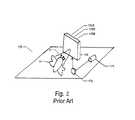
- FIG. 2is a perspective view of a prior art scanning laser based camera (SLBC) that implements a MEMS scanner with three photoreceptors.
- SLBCscanning laser based camera
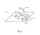
- FIG. 3is a perspective view of the Vein Enhancer of the present invention with a MEMS scanner that implements two photodiodes.
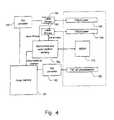
- FIG. 4is a functional block diagram that illustrates the present invention operating in Alternating Frame Mode (AFM).
- FAMAlternating Frame Mode
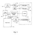
- FIG. 5is a functional block diagram that illustrates the present invention operating in Dual Buffer Mode (DBM).
- DBMDual Buffer Mode
- FIG. 6is a functional block diagram that illustrates the present invention operating in Real-Time Mode (RTM).
- RTMReal-Time Mode
- FIG. 7is a functional block diagram that illustrates the interfaces between different components of the present invention.
- FIG. 8is a perspective view of the present invention with a polarizing filter and an infrared filter placed in front of the photodiode.
- the present inventioncan be arranged as either a binary system or grayscale system.
- a grayscale systemthe 740 nm signal received by the PD is simply echoed and re-transmitted by the visible 638 nm laser 201 .
- various levels of intensitycan be shown.
- the image of a veinmay vary in intensity as a function of the magnitude of signal received.
- the projected imageis either on or off.
- a comparator with a trip pointis placed after the photodiode. If the signal crosses the trip point the output laser 638 nm 201 is turned on and vice versa.
- a user dial or press buttoncould be placed on the device, and the user can manually adjust the trip point (essentially making the device more or less sensitive).
- the vein enhancer of the present inventionimplements at least two lasers, 201 and 202 , contained in the same housing, as seen in FIG. 1 , which makes for easier operability and maintainability, that is, less chance of losing one of the devices, as in citied prior art.
- the present inventionhas: improved beam combiner glass, higher power IR, improved mirrors, smaller photo diode setup; used for collection optics, cables for electronic hook-up, AGC, and a microprocessor; used for mirror control and laser calibration.
- Laser projection deviceshave agency regulations dictating power output limitations. Generally, the power of a laser is limited to a threshold level so as to protect the user's eye from injury. If, however, the user's eye is prevented from getting too close to the laser, then the power of the laser may be increased.
- Prior art in the pasthave implemented physical barriers that are incorporated into the design of the laser. These barriers help prevent the user's eye from getting too close to the origin of the laser projections, thus laser power may be increased. For example, previous prior art have used protruding bars (similar to those used in football helmets) that are placed in the direction of the optical path. This prevents the user from placing an eye too close to the laser.
- signal processingcan be utilized to control the power output.
- the acquired image patternis stored in a computer memory.
- the imageis then processed to determine whether veins are present, and only upon confirmation of the vein being present is the image projected. In this manner, the visible laser will not be turned on if the laser is in the direction of the user.
- the power of the 740 nm laser 202can be set to an initially low setting. Once the laser detects a vein, the power of the 740 nm laser 202 can be increased and the 638 nm laser 201 turned on.
- the lasercan be configured so that the laser will only be activated when a proximity sensor 220 determines the surface, or eye of a user.
- the interface of proximity sensor 220 and the main electronics 260may be seen in FIG. 7 .
- vein enhancer of the present inventionmay be configured to operate in a multitude of ways, it includes at least one laser, one photo diode and at least one mirror. Depending on the desired output and/or operating costs additional components may be incorporated into the design of the present invention. Two embodiments that have been found useful in the vein enhancement art will now be discussed, a discussion of alternative embodiments will follow.
- Both embodimentsimplement 2 photo diodes (hereinafter PDs) and at least two lasers.
- PDsphoto diodes
- Co-axially aligning the two laserscan be achieved in a multitude of ways. Two methods that have proven to be effective include implementing, either, a dielectric mirror or a polarizer.
- the first configurationincludes a first laser calibrated to transmit light in the Infrared (hereinafter IF) spectrum, that is 740 nm, and a second laser calibrated to transmit a light in the red color spectrum, that is ⁇ 638 nm.
- the first configurationimplements a hot mirror 204 coated with a Dichroic substance, which separates and directs the light onto two separate diodes. This system allows the visible and IR laser reflections in real-time without the use of a memory chip.
- the 638 nm laser 201is oriented behind the dielectric mirror.
- the dielectric mirroris selected so that the 638 nm laser light passed through but the 740 nm is reflected.
- the 740 nm laseris aimed at the front of the dielectric mirror and is angled an claimed so that the refection of the 740 nm laser is coaxial with the 638 nm laser passing through the dielectric.
- the 638 nm laseris polarized in a first orientation and is placed behind the polarized element.
- the polarized elementis selected so that the first polarized orientation passes through, but the second polarized angle is reflected.
- the 740 nmis polarized to the second polarized angle and is aimed at the front of the polarized element and is angled and aimed so that the reflection of the 740 nm laser is coaxial with the 638 nm laser passing through the polarized element.
- the two lasersare multiplexed.
- the signal received by the 740 nm PD of the present inventionis representative of both the veins and the surface topology of the patient.
- the surface of the patientaffects the reflected signal. This is not desirable, in that the area of interest is the veins of the patient and not the surface topology of the patient.
- the microprocessor 250 or state machine circuitcan record the reflection from the visible laser and the IR laser can be turned on for one frame, every other frame, or every other scan line. Hence, a new signal would contain a combined laser reflection. The new signal would then be subtracted from the visible signal only, thus leaving the IF signal.
- the advantage hereis that the visible laser does not have to be turned off, which has the benefit of not attenuating the visible light while reading the IF laser reflection.
- a Multi laser arraymay replace the single visible laser and single IR laser.
- the linear array of visible lasers and linear array of IR lasersare reflected off a single mirror that oscillates.
- An advantage of this laser configurationis twofold. First, the mirrors being implemented are less complex. Second, the collection means of the reflected IR light can be obtained by a retro collective mirror.
- a retro collective mirroris a mirror that has a field of view that corresponds to the array of lasers and moves in concert with the movement of the array of lasers.
- SNRsignal to noise ratio
- PD 207it may be desired to implement one PD 207 , as can be seen in FIGS. 1 and 8 .
- that PDis usually responsive to the 740 nm wavelength but not the 638 nm wavelength. In this manner both lasers can be on at the same time without having the 638 laser couple into the PD.
- the same resultscan also be achieved via opposite modulation.
- the, 638 nm and 740 nm, lasersmay be modulated oppositely.
- the PDwill also be responsive to the, 638 nm and 740 nm, laser, but the lasers will be modulated in opposite directions. More specifically, both the lasers can be pulsed on and off at high rates without affecting the apparent quality of the image (638 nm projection), or the quality of the acquired image (the reflections of the 740 nm laser).
- the image acquisition circuitsBy synchronizing the two lasers so that the modulation is in opposite directions (the 638 nm on and 740 nm off, followed by, 638 nm off and 740 nm on), the image acquisition circuits (PD and amplifiers, if implemented) can be arranged to ignore signals when the 638 nm laser is on. In this embodiment, the visible 638 nm laser does not interfere at all with the image acquisition apparatus.
- the present inventionalso includes a means for gain control.
- Two possible methods of adjusting the gain of the systemare possible.
- a prior art method of adjusting gainis to fix the 740 nm laser output and to adjust the gain of the photo detection circuitry so as to get an appropriate signal (not too low and not saturated).
- An alternative approach, as in the present inventionis to fix the gain of the photo detection circuitry, as in prior art, but adjust the power output of the 740 nm laser so that an appropriate signal is outputted from the photo detection circuitry (once again not too low, but not saturated). It is much easier to design circuits that adjust the 740 nm lasers due to the extremely high modulation bandwidth of the lasers.
- the 740 nm lasermay be modulated as needed to prevent saturation of the photo detector circuitry.
- the amplitude of the 740 nm lasercan be adjusted to provide appropriate signal out of the photo, detection circuitry.
- adjusting the power of either the 638 nm laser, or 740 nm lasercan be achieved by either adjusting the current to the lasers, or alternatively, modulating the lasers on and off at a rapid rate.
- modulationdepending upon the duty cycle (pulse-width-modulation), the average laser intensity will be changed.
- the human eyeWith respect to the visible 638 nm laser, the human eye will integrate the signal and, provided the frequency of the PWM is faster than the eye integration time, the laser will appear dimmer as the on cycle time decreases, and vice versa.
- the power of the 740 nm lasermay be also be adjusted by PWM, this modulation will have the same effect upon the received signal as if the current was decreased to the laser.
- FIG. 2shows a prior art scanning laser-based camera (hereinafter SLBC) 170 of Microvision, Inc.
- the SLBC 170includes a laser source 171 which gets reflected off mirror 172 to a MEMS scanner 173 .
- the MEMS scanner 173has a reflective surface that can be oscillated in both the X and Y axis.
- the oscillation of the MEMS scanner 173is controlled by electronics (not shown) so that the reflected laser beam is moved in a raster pattern.
- the laser sourceis a combination of a red, green and blue laser, thereby forming the color white.
- Three photodetectorsone responsive to red 175 R, one responsive to blue 175 B, and one responsive to green 175 G are positioned on the SLBC 170 and receive the rastered laser light reflected off object 176 .
- the output of the photodetectors 175 R, 175 B, and 175 Bprovide an analog rastered image representative of the object 176 .
- the outputs of the photodetectorsare converted from an analog signal to a digital signal by D/A converters (not shown).
- a controller(not shown) determines the instantaneous rastered laser light position and converts that to an appropriate pixel location.
- the controllerthen writes the digitized RGB values to an appropriate pixel memory location. By repeating this step for each pixel location, a digitized version of the object is stored in memory.
- Each raster sweep of the field of view 4results in a new image being stored. By sweeping at video rates, video images can be captured.
- FIGS. 4-6Drawing one's attention to FIGS. 4-6 are three different modes of operation that the present invention may be used, a brief description of each mode of operation follows.
- a first mode of operationwhich will be referred to hereinafter as an “Alternating Frame Mode” (AFM) may be seen in FIG. 4 .
- AFMAlternating Frame Mode
- an electronic block 192 for driving the MEMS driver and for sensing the position of the raster scanneris provided 192 .
- This blockgenerates the signals required to drive the MEMS scanner 173 in a raster pattern, and also determines the exact instantaneous location of the MEMS scanner and communicates this information to an image memory 191 .
- This electronic block 192also generates output signals and indicates whether the current frame (a frame is a complete raster of the field of view) is an odd number Frame 1 or an even number Frame 2 (essentially the two signals are opposite and switch polarity every other frame). The operation is as follows.
- the MEMS 173is driven in a raster pattern.
- the first full frame after achieving a stable raster patternwill be identified as an odd number frame and the laser driver 195 for the 740 nm laser 183 is turned on for the entire frame.
- the laser drive 194 for the 630 nm laseris turned off.
- the light from the 740 nmis absorbed by the veins in a patient's body and reflected by the skin of the patient, thus forming a contrasted image that is then sensed and converted into an analog signal by 740 nm photodetector 182 .
- the analog signalis then passed through an A/D converter 190 which outputs a digital representation to image memory 191 .
- Image memory 191also receives instantaneous position information from the electronic block 192 , and based upon such information, the digital representation is stored in a memory location corresponding to a particular pixel. This is repeated for each pixel within the odd frame. Upon completion of the odd frame, the image memory contains the image of the veins within the field of view of the MPH. During the even number frame, the laser driver 195 to the 740 nm laser is turned off. The data in the image memory 191 is read out as a function of the instantaneous position information provide by the electronic block 192 and provide to a D/A converter 193 which outputs an analog signal to laser drive 194 which drives the 630 nm laser. In this manner, the image that was stored in the odd number frame is projected by the 630 nm laser 180 in the even number frame. In this manner, the veins that are in the field of view become visible to the practitioner.
- a second mode of operationis shown in FIG. 5 .
- This modeshall be referred to hereinafter as the “Dual Buffer Mode” (DBM).
- DBMa second image memory called image memory two 196 is added.
- the laser driver to the 740 nm laseris turned on for every frame and in each frame the image of the veins is captured and stored in image memory 191 exactly as described previously in the AFM mode.
- the electronic block 192provides an end of frame indication to both image memory two 196 and image memory 191 which causes the entire image stored in the image memory 191 to be transferred to image memory two 196 during the blanking time of the raster scan (the time after the raster scan is completed but before the next raster scan starts).
- the DBM modeis advantaged as compared to the AFM in that the visible laser is on every frame, and therefore is twice as bright.
- the AFM modeis advantaged in that it only requires a single memory buffer and therefore is more cost effective than the DBM mode.
- RTMReal Time Mode
- the MEMS 173is driven in a raster pattern by a MEMS driver 210 .
- the laser driver 195 to the 740 nm laseris turned on all the time.
- the reflected lightis received by the 740 nm photodetector 182 and the analog signal produced is connected to the laser driver 194 for the 630 nm laser 180 .
- the red laser 180projects nearly instantaneously the signal that is being received by the photodetector 182 .
- the only delayis dictated by the speed of the photodetector and the laser drive 194 circuitry.
- FIG. 1is a preferred embodiment 200 of a MPH the present invention.
- This embodimentreplaces the MEMS scanner with a two dimensional mirror.
- One such two dimensional mirroris provided by Fraunhofer IPMS. In a press release dated Jan. 3, 2005 they described a two dimensional mirror as follows:
- “Projection devices based on laser scanningare a very interesting alternative to matrix displays.
- a modulated laser and a deflection unitare necessary.
- micro scanning mirrorsfor implementing the laser beam deflection in a projection device has many advantages.
- micro scanning mirrorswhich operate resonantly in both directions, enable the development of systems with very small size, high deflection angles with low voltage and low power consumption.
- the presented demonstratoruses a commercial laser module and a 2D micro scanning mirror operated with deflection frequencies of 9.4 kHz and 1.4 kHz.
- the deviceuses both axes to perform a sinusoidal oscillation, which causes a beam trajectory that describes a Lissajous pattern with high density, instead of the usually implemented linear scanning.
- micro scanning mirrorswith low ratio of horizontal and vertical deflection frequency can be used.
- This kind of micro scanning mirrorscan be fabricated easily and cost effective.
- the control circuitis developed with an FPGA and provides a resolution of 256 ⁇ 256 monochromatic pixels.
- Programmable countersare used for generating the mirror driving signals and for determining the beam position.
- Mirror excitation and image synchronizationwork without feedback loop. This means, no complicated optical or electronic synchronization techniques are needed. This simplifies micro scanning mirror and control circuit and enables low cost production.
- Applications of the projection deviceare displays, laser marking and laser exposure.”
- the two-dimensional mirror of Fraunhofer IPMScreates a Lissajous pattern with high density instead of the raster pattern.
- the visible laserwill simply follow nearly instantaneously the image detected by the 740 nm laser detector.
- the MPH 200may also include two laser sources.
- a first laser source 201having a wavelength in the visible light spectrum, preferably ⁇ 632 nm, and a second laser 202 having a wavelength preferably ⁇ 740 nm, that is IR.
- Lasers 201 and 202may be any suitable lasers known in the art.
- Combiner 203may have at least one bounce mirror. In a preferred embodiment there can be two bounce mirrors, 203 a and 203 b . In the preferred embodiment combiner 203 may also include a dielectric coated mirror 204 . Mirror 204 may be any suitable type of dielectric coated mirror known in the available art. In a preferred embodiment mirror 204 was coated with a material that reflects IR and transmits other wavelengths. As mentioned above, the embodiment as depicted in FIG. 1 replaces the MEMS scanner with a two dimensional scanning mirror 205 , such as the type provided by Fraunhofer IPMS. With this embodiment there can also be a collection mirror 206 , and at least one PD 207 .
- the embodiment as depicted in FIG. 1operates as previously discussed, that is, in any of the three operating modes; however, it performs optimally in RTM.
- Mirror 206is preferably coated with a dichroic coating. This acts as a beam splitter. In normal operation mirror 206 will direct the light onto two separate PDs. With this type of embodiment all other previously mentioned components may operate in the same manner.
- laser 202will transmit IR light 220 which will bounce off of bounce mirror 203 a . At which time laser 202 will begin to transmit light 221 at ⁇ 632 nm.
- Light 221will pass through dielectric coated mirror 204 and light 220 will reflect of mirror 204 , resulting in a beam of light 222 that is a combination of both lights, as seen in FIG. 1 .
- Beam 222will then be reflected of bounce mirror 203 b .
- the angle at which beam 222 is reflectedwill depend on the angle at which bounce mirror 203 b is placed. This will be determined by the manufacturer's design requirements.
- beam 222will be projected onto the area of interest, that is, the area where the vein is located, via two dimensional scanning-mirrors 205 .
- the projected beam 222will then be collected by collection mirror 206 . After which, collected beam will then be passed through hot mirror 206 to separate and direct beam 222 onto two PDs 207 .
- This embodimentcompares the visible light and the IR laser reflections in real-time, without a memory chip.
- FIG. 3Other embodiments may implement a MEMS scanner, as seen in FIG. 3 , to perform the same function as the two dimensional mirrors. This will depend on economic as well as practicable considerations.
- polarizing filters and/or infrared filterslocated between the collection mirror and the photodiode, as seen in FIG. 8 .
- the visible light transmittedwas a red laser.
- any visible color or combination of colorcould be transmitted.
- three laser RGBcould be utilized to transmit full color images onto the field of view.
- the outgoing laser beamscan be bounced first off a one dimensional high speed scanning mirror and then off a second lower speed mirror scanning in the opposite direction.
- the outgoing laser beamscan be bounced first off a one dimensional high speed scanning mirror and then off a second lower speed mirror scanning in the opposite direction.
Landscapes
- Health & Medical Sciences (AREA)
- Life Sciences & Earth Sciences (AREA)
- General Health & Medical Sciences (AREA)
- Animal Behavior & Ethology (AREA)
- Engineering & Computer Science (AREA)
- Biomedical Technology (AREA)
- Heart & Thoracic Surgery (AREA)
- Veterinary Medicine (AREA)
- Public Health (AREA)
- Pathology (AREA)
- Vascular Medicine (AREA)
- Physics & Mathematics (AREA)
- Biophysics (AREA)
- Medical Informatics (AREA)
- Molecular Biology (AREA)
- Surgery (AREA)
- Dermatology (AREA)
- Hematology (AREA)
- Anesthesiology (AREA)
- Nuclear Medicine, Radiotherapy & Molecular Imaging (AREA)
- Radiology & Medical Imaging (AREA)
- Eye Examination Apparatus (AREA)
Abstract
Description
Claims (30)
Priority Applications (6)
| Application Number | Priority Date | Filing Date | Title |
|---|---|---|---|
| US11/985,343US8255040B2 (en) | 2006-06-29 | 2007-11-14 | Micro vein enhancer |
| US12/804,088US20160296146A9 (en) | 2006-06-29 | 2010-07-13 | Apparatus-Mounted Vein Contrast Enchancer |
| US13/444,940US8750970B2 (en) | 2006-01-10 | 2012-04-12 | Micro vein enhancer |
| US14/249,462US10813588B2 (en) | 2006-01-10 | 2014-04-10 | Micro vein enhancer |
| US17/027,972US11638558B2 (en) | 2006-01-10 | 2020-09-22 | Micro vein enhancer |
| US18/135,798US12295744B2 (en) | 2006-01-10 | 2023-04-18 | Micro vein enhancer with two lasers and two optical detectors configured for removing surface topology |
Applications Claiming Priority (3)
| Application Number | Priority Date | Filing Date | Title |
|---|---|---|---|
| US81762306P | 2006-06-29 | 2006-06-29 | |
| US11/478,322US8478386B2 (en) | 2006-01-10 | 2006-06-29 | Practitioner-mounted micro vein enhancer |
| US11/985,343US8255040B2 (en) | 2006-06-29 | 2007-11-14 | Micro vein enhancer |
Related Parent Applications (3)
| Application Number | Title | Priority Date | Filing Date |
|---|---|---|---|
| US11/478,322Continuation-In-PartUS8478386B2 (en) | 2006-01-01 | 2006-06-29 | Practitioner-mounted micro vein enhancer |
| US11/700,729Continuation-In-PartUS8838210B2 (en) | 2006-01-10 | 2007-01-31 | Scanned laser vein contrast enhancer using a single laser |
| US11/807,255Continuation-In-PartUS8380291B2 (en) | 2006-01-10 | 2007-05-25 | Scanned laser vein contrast enhancer |
Related Child Applications (2)
| Application Number | Title | Priority Date | Filing Date |
|---|---|---|---|
| US11/807,064Continuation-In-PartUS8391960B2 (en) | 2006-01-10 | 2007-05-25 | Scanned laser vein contrast enhancer |
| US13/444,940ContinuationUS8750970B2 (en) | 2006-01-10 | 2012-04-12 | Micro vein enhancer |
Publications (2)
| Publication Number | Publication Date |
|---|---|
| US20080177184A1 US20080177184A1 (en) | 2008-07-24 |
| US8255040B2true US8255040B2 (en) | 2012-08-28 |
Family
ID=39641964
Family Applications (2)
| Application Number | Title | Priority Date | Filing Date |
|---|---|---|---|
| US11/985,343Active2029-05-03US8255040B2 (en) | 2006-01-10 | 2007-11-14 | Micro vein enhancer |
| US13/444,940Active2026-10-03US8750970B2 (en) | 2006-01-10 | 2012-04-12 | Micro vein enhancer |
Family Applications After (1)
| Application Number | Title | Priority Date | Filing Date |
|---|---|---|---|
| US13/444,940Active2026-10-03US8750970B2 (en) | 2006-01-10 | 2012-04-12 | Micro vein enhancer |
Country Status (1)
| Country | Link |
|---|---|
| US (2) | US8255040B2 (en) |
Cited By (17)
| Publication number | Priority date | Publication date | Assignee | Title |
|---|---|---|---|---|
| US20120280972A1 (en)* | 2011-05-02 | 2012-11-08 | Microvision, Inc. | Dual Laser Drive Method, Apparatus, and System |
| US9042967B2 (en) | 2008-05-20 | 2015-05-26 | University Health Network | Device and method for wound imaging and monitoring |
| WO2015120026A1 (en) | 2014-02-04 | 2015-08-13 | Medical Components, Inc. | Light based location and identification of implanted medical devices |
| US10251600B2 (en) | 2014-03-25 | 2019-04-09 | Briteseed, Llc | Vessel detector and method of detection |
| US10438356B2 (en) | 2014-07-24 | 2019-10-08 | University Health Network | Collection and analysis of data for diagnostic purposes |
| US10716508B2 (en) | 2015-10-08 | 2020-07-21 | Briteseed, Llc | System and method for determining vessel size |
| US10820838B2 (en) | 2015-02-19 | 2020-11-03 | Briteseed, Llc | System for determining vessel size using light absorption |
| US10850045B2 (en) | 2014-04-03 | 2020-12-01 | Toppan Printing Co., Ltd. | Puncture injection instrument |
| US11207024B2 (en)* | 2017-07-12 | 2021-12-28 | Boe Technology Group Co., Ltd. | Vascular imaging apparatus and vascular imaging method |
| US11399898B2 (en) | 2012-03-06 | 2022-08-02 | Briteseed, Llc | User interface for a system used to determine tissue or artifact characteristics |
| US11490820B2 (en) | 2015-02-19 | 2022-11-08 | Briteseed, Llc | System and method for determining vessel size and/or edge |
| US11589852B2 (en) | 2016-08-30 | 2023-02-28 | Briteseed, Llc | Optical surgical system having light sensor on its jaw and method for determining vessel size with angular distortion compensation |
| US11696777B2 (en) | 2017-12-22 | 2023-07-11 | Briteseed, Llc | Compact system used to determine tissue or artifact characteristics |
| US11723600B2 (en) | 2017-09-05 | 2023-08-15 | Briteseed, Llc | System and method used to determine tissue and/or artifact characteristics |
| US11992338B2 (en) | 2018-12-30 | 2024-05-28 | Briteseed, Llc | System and method used to detect or differentiate tissue or an artifact |
| US11992235B2 (en) | 2016-02-12 | 2024-05-28 | Briteseed, Llc | System to differentiate and identify types of tissue within a region proximate to a working end of a surgical instrument |
| US12220255B2 (en) | 2020-07-30 | 2025-02-11 | Novotec Llc | Vessel location assistance device |
Families Citing this family (6)
| Publication number | Priority date | Publication date | Assignee | Title |
|---|---|---|---|---|
| US8730321B2 (en)* | 2007-06-28 | 2014-05-20 | Accuvein, Inc. | Automatic alignment of a contrast enhancement system |
| US8364246B2 (en)* | 2007-09-13 | 2013-01-29 | Sure-Shot Medical Device, Inc. | Compact feature location and display system |
| JP2013515266A (en)* | 2009-12-21 | 2013-05-02 | テルモ株式会社 | Excitation / detection / projection system to visualize target cancer tissue |
| US10517483B2 (en)* | 2012-12-05 | 2019-12-31 | Accuvein, Inc. | System for detecting fluorescence and projecting a representative image |
| US9622720B2 (en)* | 2013-11-27 | 2017-04-18 | Clear Guide Medical, Inc. | Ultrasound system with stereo image guidance or tracking |
| US10928617B1 (en)* | 2018-05-18 | 2021-02-23 | GDH Enterprises, LLC | Portable three-dimensional virtual imaging device |
Citations (49)
| Publication number | Priority date | Publication date | Assignee | Title |
|---|---|---|---|---|
| FR2289149A1 (en) | 1974-11-04 | 1976-05-28 | Siemens Ag | DEVICE FOR PRECISELY AND RAPID LOCATION OF VESSELS CROSSED BY LIQUIDS IN THE HUMAN BODY AND FOR PRECISELY INTRODUCING A PUNCTURE CANNULA IN THESE VESSELS |
| US4502075A (en) | 1981-12-04 | 1985-02-26 | International Remote Imaging Systems | Method and apparatus for producing optical displays |
| US4619249A (en) | 1985-07-24 | 1986-10-28 | Kim Landry | Transcutaneous intravenous illuminator |
| US4817622A (en) | 1986-07-22 | 1989-04-04 | Carl Pennypacker | Infrared imager for viewing subcutaneous location of vascular structures and method of use |
| US5214458A (en) | 1992-01-14 | 1993-05-25 | Matsubara Kenki Kogyo Kabushiki Kaisha | Display apparatus |
| WO1994022370A1 (en) | 1993-04-01 | 1994-10-13 | British Technology Group Limited | Biometric identification of individuals |
| US5406070A (en) | 1993-12-16 | 1995-04-11 | International Business Machines Corporation | Method and apparatus for scanning an object and correcting image data using concurrently generated illumination data |
| US5519208A (en) | 1994-09-29 | 1996-05-21 | Esparza; Joel | Infrared aided method and apparatus for venous examination |
| US5541820A (en) | 1995-01-26 | 1996-07-30 | Mclaughlin; Michael K. | Combined lamp and movie projector |
| WO1996039925A1 (en) | 1995-06-07 | 1996-12-19 | University Of Arkansas | Method and apparatus for detecting electro-magnetic reflection from biological tissue |
| US5608210A (en) | 1994-09-29 | 1997-03-04 | Esparza; Joel | Infrared aided method and apparatus for venous examination |
| US5631976A (en) | 1994-04-29 | 1997-05-20 | International Business Machines Corporation | Object imaging system |
| US5678555A (en) | 1996-04-08 | 1997-10-21 | O'connell; Peter | Method of locating and marking veins |
| WO1998026583A1 (en) | 1996-12-09 | 1998-06-18 | Zeman Herbert D | Contrast enhancing illuminator |
| US5772593A (en) | 1995-07-12 | 1998-06-30 | Fuji Photo Film Co., Ltd. | Surgical operation aiding system |
| US5836877A (en)* | 1997-02-24 | 1998-11-17 | Lucid Inc | System for facilitating pathological examination of a lesion in tissue |
| US5860967A (en) | 1993-07-21 | 1999-01-19 | Lucid, Inc. | Dermatological laser treatment system with electronic visualization of the area being treated |
| US5995866A (en)* | 1995-03-21 | 1999-11-30 | Lemelson; Jerome | Method and apparatus for scanning and evaluating matter |
| US5995856A (en)* | 1995-11-22 | 1999-11-30 | Nellcor, Incorporated | Non-contact optical monitoring of physiological parameters |
| US6061583A (en) | 1995-12-27 | 2000-05-09 | Sysmex Corporation And Ken Ishihara | Noninvasive blood analyzer |
| US6135599A (en) | 1999-03-26 | 2000-10-24 | Fang; Chen-Tai | Projection ornament |
| US6263227B1 (en)* | 1996-05-22 | 2001-07-17 | Moor Instruments Limited | Apparatus for imaging microvascular blood flow |
| WO2001082786A2 (en) | 2000-05-03 | 2001-11-08 | Flock Stephen T | Optical imaging of subsurface anatomical structures and biomolecules |
| WO2003009750A2 (en) | 2001-07-25 | 2003-02-06 | Sarnoff Corporation | System and method for determining brain oxygenation |
| US6542246B1 (en) | 1998-11-20 | 2003-04-01 | Fuji Photo Film Co., Ltd. | Blood vessel imaging system |
| US6556854B1 (en) | 1998-11-20 | 2003-04-29 | Fuji Photo Film Co., Ltd. | Blood vessel imaging system using homodyne and heterodyne effects |
| US6782161B2 (en) | 2001-02-05 | 2004-08-24 | Derma Laser Inc. | Laser diode apparatus provided with an aiming beam and injection method therefor |
| JP2004237051A (en) | 2003-02-06 | 2004-08-26 | Ogawa Hiroteru | Blood vessel visualizing method and apparatus |
| US20050043596A1 (en) | 1996-07-12 | 2005-02-24 | Non-Invasive Technology, Inc., A Delaware Corporation | Optical examination device, system and method |
| US6882875B1 (en)* | 1997-09-29 | 2005-04-19 | Boston Scientific Corporation | Visible display for an interventional device |
| US20050113650A1 (en) | 2000-06-16 | 2005-05-26 | Christopher Pacione | System for monitoring and managing body weight and other physiological conditions including iterative and personalized planning, intervention and reporting capability |
| US20050141069A1 (en) | 2003-12-31 | 2005-06-30 | Wood Frederick F. | Method and apparatus for conserving power in a laser projection display |
| US20050161051A1 (en) | 2003-01-08 | 2005-07-28 | Cyberheart, Inc. | System for non-invasive heart treatment |
| US20050174777A1 (en) | 2004-02-10 | 2005-08-11 | Rita Cooper | Sensor-activated audible story lamp |
| US20050215875A1 (en) | 2004-03-19 | 2005-09-29 | Sroy Khou | Method and device for locating position of veins on body |
| US20050281445A1 (en) | 2004-01-16 | 2005-12-22 | Ronald Marcotte | System and method for locating and accessing a blood vessel |
| US6980852B2 (en) | 2002-01-25 | 2005-12-27 | Subqiview Inc. | Film barrier dressing for intravascular tissue monitoring system |
| US20060232660A1 (en) | 2002-07-02 | 2006-10-19 | Tomohiro Nakajima | Optical scanner and image forming apparatus |
| US20060253010A1 (en) | 2004-09-28 | 2006-11-09 | Donald Brady | Monitoring device, method and system |
| US20060271028A1 (en) | 2005-02-18 | 2006-11-30 | Palomar Medical Technologies, Inc. | Dermatological treatment device |
| US20070016079A1 (en) | 2005-04-04 | 2007-01-18 | Freeman Jenny E | Hyperspectral imaging in diabetes and peripheral vascular disease |
| US7239909B2 (en)* | 2000-01-19 | 2007-07-03 | Luminetx Technologies Corp. | Imaging system using diffuse infrared light |
| US7247832B2 (en)* | 2005-09-09 | 2007-07-24 | Silicon Light Machines Corporation | Signal processing circuit and method using analog voltage signal to pulse width modulation conversion |
| US7333213B2 (en)* | 1998-05-28 | 2008-02-19 | The General Hospital Corporation | Confocal microscopy |
| US20080147147A1 (en)* | 2006-12-18 | 2008-06-19 | Medrad, Inc. | Vein locating device for vascular access procedures |
| US20090021746A1 (en)* | 2005-01-14 | 2009-01-22 | Fujifilm Corporation | Tomography apparatus |
| US20100051808A1 (en)* | 2007-10-19 | 2010-03-04 | Luminetx Corporation | Imaging System Using Infrared Light |
| US20100177184A1 (en)* | 2007-02-14 | 2010-07-15 | Chrustie Medical Holdings, Inc. | System And Method For Projection of Subsurface Structure Onto An Object's Surface |
| US7783337B2 (en)* | 2005-06-06 | 2010-08-24 | Board Of Regents, The University Of Texas System | OCT using spectrally resolved bandwidth |
Family Cites Families (74)
| Publication number | Priority date | Publication date | Assignee | Title |
|---|---|---|---|---|
| US3527932A (en) | 1967-11-16 | 1970-09-08 | James J Thomas | Transilluminating flashlight |
| DE1927868C3 (en) | 1969-05-31 | 1975-06-05 | Siemens Ag, 1000 Berlin Und 8000 Muenchen | Device for the precise and rapid location of blood vessels or the like and for the accurate insertion of an injection cannula into these vessels |
| US3818129A (en) | 1971-06-30 | 1974-06-18 | Hitachi Ltd | Laser imaging device |
| US4185808A (en) | 1975-02-10 | 1980-01-29 | Cbs Inc. | Connector hardware for percussive instruments |
| SE7613587L (en) | 1976-12-03 | 1978-06-04 | Andersson Torsten | METHOD FOR DIAGNOSIS OF DISEASE CHANGES IN WOMEN'S BREAST |
| US4281645A (en) | 1977-06-28 | 1981-08-04 | Duke University, Inc. | Method and apparatus for monitoring metabolism in body organs |
| US4182322A (en) | 1978-08-04 | 1980-01-08 | Miller Larry C | Head harness device |
| US4265227A (en) | 1979-10-03 | 1981-05-05 | The Hospital And Welfare Board Of Hillsborough County | Infant extremity positioner and illuminator |
| US4495949A (en) | 1982-07-19 | 1985-01-29 | Spectrascan, Inc. | Transillumination method |
| DE3709709A1 (en) | 1986-03-25 | 1987-10-08 | Asahi Optical Co Ltd | AUXILIARY LIGHT PROJECTING DEVICE FOR A REMOVAL LOCKING SYSTEM |
| US4766299A (en) | 1986-03-28 | 1988-08-23 | Spectra-Physics, Inc. | Hand-mounted bar code reader |
| US4780919A (en) | 1987-10-20 | 1988-11-01 | Harrison Mildred B | Hospital bed |
| US5504316A (en) | 1990-05-08 | 1996-04-02 | Symbol Technologies, Inc. | Laser scanning system and scanning method for reading 1-D and 2-D barcode symbols |
| US7077327B1 (en) | 1990-09-17 | 2006-07-18 | Metrologic Instruments, Inc. | System for reading bar code symbols using bar code readers having RF signal transmission links with base stations |
| US5610387A (en) | 1992-05-15 | 1997-03-11 | Symbol Technologies, Inc. | Portable optical scanning system worn by a user for reading indicia of differing light reflectivity |
| US5756981A (en) | 1992-02-27 | 1998-05-26 | Symbol Technologies, Inc. | Optical scanner for reading and decoding one- and-two-dimensional symbologies at variable depths of field including memory efficient high speed image processing means and high accuracy image analysis means |
| US5261581A (en) | 1992-04-10 | 1993-11-16 | Harden Sr Ralph E | Holster for bow string release or tool |
| IL104423A (en) | 1993-01-18 | 1998-09-24 | Opgal Optronic Ind Ltd | Infra-red vascular angiography system |
| US6648227B2 (en) | 2000-10-20 | 2003-11-18 | Symbol Technologies, Inc. | Scanning module for a bar code reader with a focusing lens |
| US5423091A (en) | 1994-09-22 | 1995-06-13 | The Tram Corporation | Headband following a wearer's hairline |
| US6230046B1 (en) | 1995-05-16 | 2001-05-08 | The United States Of America As Represented By The Secretary Of The Air Force | System and method for enhanced visualization of subcutaneous structures |
| JPH10301202A (en) | 1997-02-28 | 1998-11-13 | R D S Kk | Multiprojection system |
| US5982553A (en) | 1997-03-20 | 1999-11-09 | Silicon Light Machines | Display device incorporating one-dimensional grating light-valve array |
| KR100259475B1 (en) | 1997-04-14 | 2000-06-15 | 최환수 | Method for the identification of individuals using the pattern of blood vessels |
| US6142650A (en) | 1997-07-10 | 2000-11-07 | Brown; David C. | Laser flashlight |
| US7125397B2 (en) | 1997-08-20 | 2006-10-24 | B. Braun Melsungen Ag | Protective device for an injection needle |
| US20040052076A1 (en) | 1997-08-26 | 2004-03-18 | Mueller George G. | Controlled lighting methods and apparatus |
| US7028899B2 (en) | 1999-06-07 | 2006-04-18 | Metrologic Instruments, Inc. | Method of speckle-noise pattern reduction and apparatus therefore based on reducing the temporal-coherence of the planar laser illumination beam before it illuminates the target object by applying temporal phase modulation techniques during the transmission of the plib towards the target |
| US6334850B1 (en) | 1997-11-19 | 2002-01-01 | Seiko Epson Corporation | Method of detecting pulse wave, method of detecting artery position, and pulse wave detecting apparatus |
| US6149644A (en) | 1998-02-17 | 2000-11-21 | Altralight, Inc. | Method and apparatus for epidermal treatment with computer controlled moving focused infrared light |
| FR2775589B1 (en) | 1998-03-06 | 2000-04-28 | Cryonic Medical | SELF-CONTAINED, PORTABLE CRYOGENIC APPARATUS USING CARBONIC ANHYDRIDE IN LIQUID / SOLID PHASE |
| IL123787A0 (en) | 1998-03-23 | 1998-10-30 | Veino Med Temed Ltd | Instrument for locating and marking a vein |
| US6056692A (en) | 1998-07-08 | 2000-05-02 | Schwartz; John Q. | Apparatus and method for locating and marking blood vessels |
| US6178340B1 (en) | 1998-08-24 | 2001-01-23 | Eduardo Svetliza | Three-dimensional infrared imager for subcutaneous puncture and study of vascular network |
| US6424858B1 (en) | 1998-11-12 | 2002-07-23 | John L. Williams | Apparatus and method for viewing vasculature of a human being |
| US6251073B1 (en) | 1999-08-20 | 2001-06-26 | Novasonics, Inc. | Miniaturized ultrasound apparatus and method |
| US6556858B1 (en) | 2000-01-19 | 2003-04-29 | Herbert D. Zeman | Diffuse infrared light imaging system |
| US8078263B2 (en) | 2000-01-19 | 2011-12-13 | Christie Medical Holdings, Inc. | Projection of subsurface structure onto an object's surface |
| US6463309B1 (en) | 2000-05-11 | 2002-10-08 | Hanna Ilia | Apparatus and method for locating vessels in a living body |
| DE10033723C1 (en) | 2000-07-12 | 2002-02-21 | Siemens Ag | Surgical instrument position and orientation visualization device for surgical operation has data representing instrument position and orientation projected onto surface of patient's body |
| AU2001286760B9 (en) | 2000-08-25 | 2006-05-18 | Encompass Health Corporation | Powered gait orthosis and method of utilizing same |
| JP4817509B2 (en) | 2001-02-19 | 2011-11-16 | キヤノン株式会社 | Optometry equipment |
| JP2002328428A (en) | 2001-05-01 | 2002-11-15 | Sony Corp | Projector and image projection system |
| US6886964B2 (en) | 2001-06-26 | 2005-05-03 | Allan Gardiner | Illuminator with filter array and bandwidth controller |
| US20030018271A1 (en) | 2001-07-02 | 2003-01-23 | Kimble Allan Wayne | Simplified and lightweight system for enhanced visualization of subcutaneous hemoglobin-containing structures |
| US6702749B2 (en) | 2001-07-24 | 2004-03-09 | Siemens Corporate Research, Inc. | Optical needle guide for ultrasound guided needle biopsy |
| US6923762B1 (en) | 2001-11-01 | 2005-08-02 | Frank C. Creaghan, Jr. | Venoscope apparatus |
| US6746402B2 (en) | 2002-01-02 | 2004-06-08 | E. Tuncay Ustuner | Ultrasound system and method |
| US7283181B2 (en) | 2002-01-31 | 2007-10-16 | Hewlett-Packard Development Company, L.P. | Selectable color adjustment for image display |
| US7158660B2 (en) | 2002-05-08 | 2007-01-02 | Gee Jr James W | Method and apparatus for detecting structures of interest |
| US20040004775A1 (en) | 2002-07-08 | 2004-01-08 | Turner Arthur Monroe | Resonant scanning mirror with inertially coupled activation |
| JP4387643B2 (en) | 2002-07-31 | 2009-12-16 | 富士通株式会社 | Processing device with personal recognition function |
| US20040171923A1 (en) | 2002-12-06 | 2004-09-02 | Kalafut John F. | Devices, systems and methods for improving vessel access |
| US7352340B2 (en) | 2002-12-20 | 2008-04-01 | Global Imagination | Display system having a three-dimensional convex display surface |
| US6719257B1 (en) | 2003-01-09 | 2004-04-13 | Tim L. Greene | Adjustable stop for telescoping tubes |
| US6899271B2 (en) | 2003-05-05 | 2005-05-31 | Symbol Technologies, Inc. | Arrangement for and method of collecting and displaying information in real time along a line of sight |
| US7588541B2 (en) | 2003-12-10 | 2009-09-15 | Sonosite, Inc. | Method and system for positioning a medical device at one or more angles relative to an imaging probe |
| TW200527920A (en) | 2003-12-15 | 2005-08-16 | Koninkl Philips Electronics Nv | Projector and method of projecting an image having multiple image sizes |
| US7030353B2 (en) | 2003-12-31 | 2006-04-18 | Symbol Technologies,Inc. | Method and apparatus for controllably reducing power delivered by a laser projection display |
| US7302174B2 (en) | 2003-12-31 | 2007-11-27 | Symbol Technologies, Inc. | Method and apparatus for capturing images using a color laser projection display |
| US20050157939A1 (en) | 2004-01-16 | 2005-07-21 | Mark Arsenault | Processes, products and systems for enhancing images of blood vessels |
| US7749588B2 (en)* | 2004-01-20 | 2010-07-06 | Sy Holdings, LLC | Protective coverings |
| US20060025679A1 (en) | 2004-06-04 | 2006-02-02 | Viswanathan Raju R | User interface for remote control of medical devices |
| US20060081252A1 (en) | 2004-10-19 | 2006-04-20 | Wood Thomas J | Headgear |
| US7213926B2 (en) | 2004-11-12 | 2007-05-08 | Hewlett-Packard Development Company, L.P. | Image projection system and method |
| US20060129038A1 (en) | 2004-12-14 | 2006-06-15 | Zelenchuk Alex R | Optical determination of in vivo properties |
| US7225005B2 (en) | 2004-12-14 | 2007-05-29 | Intelligent Medical Devices, Inc. | Optical determination of in vivo properties |
| US20060173351A1 (en) | 2005-01-03 | 2006-08-03 | Ronald Marcotte | System and method for inserting a needle into a blood vessel |
| US8478386B2 (en) | 2006-01-10 | 2013-07-02 | Accuvein Inc. | Practitioner-mounted micro vein enhancer |
| US8838210B2 (en) | 2006-06-29 | 2014-09-16 | AccuView, Inc. | Scanned laser vein contrast enhancer using a single laser |
| WO2008042346A2 (en) | 2006-09-28 | 2008-04-10 | Stryker Corporation | Medical equipment transfer arrangement |
| US20080194930A1 (en) | 2007-02-09 | 2008-08-14 | Harris Melvyn L | Infrared-visible needle |
| US9022940B2 (en) | 2008-07-18 | 2015-05-05 | Joseph H. Meier | Handheld imaging devices and related methods |
| JP5326792B2 (en) | 2009-05-14 | 2013-10-30 | ソニー株式会社 | Vein imaging device, positional deviation interpolation method and program |
- 2007
- 2007-11-14USUS11/985,343patent/US8255040B2/enactiveActive
- 2012
- 2012-04-12USUS13/444,940patent/US8750970B2/enactiveActive
Patent Citations (51)
| Publication number | Priority date | Publication date | Assignee | Title |
|---|---|---|---|---|
| FR2289149A1 (en) | 1974-11-04 | 1976-05-28 | Siemens Ag | DEVICE FOR PRECISELY AND RAPID LOCATION OF VESSELS CROSSED BY LIQUIDS IN THE HUMAN BODY AND FOR PRECISELY INTRODUCING A PUNCTURE CANNULA IN THESE VESSELS |
| GB1507329A (en) | 1974-11-04 | 1978-04-12 | Siemens Ag | Device for locating a position on the skin of a patient below which position lies a vessel through which body fluid flows and for the introduction of a puncturing cannula into the vessel |
| US4502075A (en) | 1981-12-04 | 1985-02-26 | International Remote Imaging Systems | Method and apparatus for producing optical displays |
| US4619249A (en) | 1985-07-24 | 1986-10-28 | Kim Landry | Transcutaneous intravenous illuminator |
| US4817622A (en) | 1986-07-22 | 1989-04-04 | Carl Pennypacker | Infrared imager for viewing subcutaneous location of vascular structures and method of use |
| US5214458A (en) | 1992-01-14 | 1993-05-25 | Matsubara Kenki Kogyo Kabushiki Kaisha | Display apparatus |
| WO1994022370A1 (en) | 1993-04-01 | 1994-10-13 | British Technology Group Limited | Biometric identification of individuals |
| US5860967A (en) | 1993-07-21 | 1999-01-19 | Lucid, Inc. | Dermatological laser treatment system with electronic visualization of the area being treated |
| US5406070A (en) | 1993-12-16 | 1995-04-11 | International Business Machines Corporation | Method and apparatus for scanning an object and correcting image data using concurrently generated illumination data |
| US5631976A (en) | 1994-04-29 | 1997-05-20 | International Business Machines Corporation | Object imaging system |
| US5519208A (en) | 1994-09-29 | 1996-05-21 | Esparza; Joel | Infrared aided method and apparatus for venous examination |
| US5608210A (en) | 1994-09-29 | 1997-03-04 | Esparza; Joel | Infrared aided method and apparatus for venous examination |
| US5541820A (en) | 1995-01-26 | 1996-07-30 | Mclaughlin; Michael K. | Combined lamp and movie projector |
| US5995866A (en)* | 1995-03-21 | 1999-11-30 | Lemelson; Jerome | Method and apparatus for scanning and evaluating matter |
| WO1996039925A1 (en) | 1995-06-07 | 1996-12-19 | University Of Arkansas | Method and apparatus for detecting electro-magnetic reflection from biological tissue |
| US5772593A (en) | 1995-07-12 | 1998-06-30 | Fuji Photo Film Co., Ltd. | Surgical operation aiding system |
| US5995856A (en)* | 1995-11-22 | 1999-11-30 | Nellcor, Incorporated | Non-contact optical monitoring of physiological parameters |
| US6061583A (en) | 1995-12-27 | 2000-05-09 | Sysmex Corporation And Ken Ishihara | Noninvasive blood analyzer |
| US5678555A (en) | 1996-04-08 | 1997-10-21 | O'connell; Peter | Method of locating and marking veins |
| US6263227B1 (en)* | 1996-05-22 | 2001-07-17 | Moor Instruments Limited | Apparatus for imaging microvascular blood flow |
| US20050043596A1 (en) | 1996-07-12 | 2005-02-24 | Non-Invasive Technology, Inc., A Delaware Corporation | Optical examination device, system and method |
| WO1998026583A1 (en) | 1996-12-09 | 1998-06-18 | Zeman Herbert D | Contrast enhancing illuminator |
| US5836877A (en)* | 1997-02-24 | 1998-11-17 | Lucid Inc | System for facilitating pathological examination of a lesion in tissue |
| US6882875B1 (en)* | 1997-09-29 | 2005-04-19 | Boston Scientific Corporation | Visible display for an interventional device |
| US7333213B2 (en)* | 1998-05-28 | 2008-02-19 | The General Hospital Corporation | Confocal microscopy |
| US6542246B1 (en) | 1998-11-20 | 2003-04-01 | Fuji Photo Film Co., Ltd. | Blood vessel imaging system |
| US6556854B1 (en) | 1998-11-20 | 2003-04-29 | Fuji Photo Film Co., Ltd. | Blood vessel imaging system using homodyne and heterodyne effects |
| US6135599A (en) | 1999-03-26 | 2000-10-24 | Fang; Chen-Tai | Projection ornament |
| US7239909B2 (en)* | 2000-01-19 | 2007-07-03 | Luminetx Technologies Corp. | Imaging system using diffuse infrared light |
| WO2001082786A2 (en) | 2000-05-03 | 2001-11-08 | Flock Stephen T | Optical imaging of subsurface anatomical structures and biomolecules |
| US20050143662A1 (en) | 2000-05-03 | 2005-06-30 | Rocky Mountain Biosystems, Inc. | Optical imaging of subsurface anatomical structures and biomolecules |
| US20050113650A1 (en) | 2000-06-16 | 2005-05-26 | Christopher Pacione | System for monitoring and managing body weight and other physiological conditions including iterative and personalized planning, intervention and reporting capability |
| US6782161B2 (en) | 2001-02-05 | 2004-08-24 | Derma Laser Inc. | Laser diode apparatus provided with an aiming beam and injection method therefor |
| WO2003009750A2 (en) | 2001-07-25 | 2003-02-06 | Sarnoff Corporation | System and method for determining brain oxygenation |
| US6980852B2 (en) | 2002-01-25 | 2005-12-27 | Subqiview Inc. | Film barrier dressing for intravascular tissue monitoring system |
| US20060232660A1 (en) | 2002-07-02 | 2006-10-19 | Tomohiro Nakajima | Optical scanner and image forming apparatus |
| US20050161051A1 (en) | 2003-01-08 | 2005-07-28 | Cyberheart, Inc. | System for non-invasive heart treatment |
| JP2004237051A (en) | 2003-02-06 | 2004-08-26 | Ogawa Hiroteru | Blood vessel visualizing method and apparatus |
| US20050141069A1 (en) | 2003-12-31 | 2005-06-30 | Wood Frederick F. | Method and apparatus for conserving power in a laser projection display |
| US20050281445A1 (en) | 2004-01-16 | 2005-12-22 | Ronald Marcotte | System and method for locating and accessing a blood vessel |
| US20050174777A1 (en) | 2004-02-10 | 2005-08-11 | Rita Cooper | Sensor-activated audible story lamp |
| US20050215875A1 (en) | 2004-03-19 | 2005-09-29 | Sroy Khou | Method and device for locating position of veins on body |
| US20060253010A1 (en) | 2004-09-28 | 2006-11-09 | Donald Brady | Monitoring device, method and system |
| US20090021746A1 (en)* | 2005-01-14 | 2009-01-22 | Fujifilm Corporation | Tomography apparatus |
| US20060271028A1 (en) | 2005-02-18 | 2006-11-30 | Palomar Medical Technologies, Inc. | Dermatological treatment device |
| US20070016079A1 (en) | 2005-04-04 | 2007-01-18 | Freeman Jenny E | Hyperspectral imaging in diabetes and peripheral vascular disease |
| US7783337B2 (en)* | 2005-06-06 | 2010-08-24 | Board Of Regents, The University Of Texas System | OCT using spectrally resolved bandwidth |
| US7247832B2 (en)* | 2005-09-09 | 2007-07-24 | Silicon Light Machines Corporation | Signal processing circuit and method using analog voltage signal to pulse width modulation conversion |
| US20080147147A1 (en)* | 2006-12-18 | 2008-06-19 | Medrad, Inc. | Vein locating device for vascular access procedures |
| US20100177184A1 (en)* | 2007-02-14 | 2010-07-15 | Chrustie Medical Holdings, Inc. | System And Method For Projection of Subsurface Structure Onto An Object's Surface |
| US20100051808A1 (en)* | 2007-10-19 | 2010-03-04 | Luminetx Corporation | Imaging System Using Infrared Light |
Cited By (31)
| Publication number | Priority date | Publication date | Assignee | Title |
|---|---|---|---|---|
| US11284800B2 (en) | 2008-05-20 | 2022-03-29 | University Health Network | Devices, methods, and systems for fluorescence-based endoscopic imaging and collection of data with optical filters with corresponding discrete spectral bandwidth |
| US9042967B2 (en) | 2008-05-20 | 2015-05-26 | University Health Network | Device and method for wound imaging and monitoring |
| US12251191B2 (en) | 2008-05-20 | 2025-03-18 | University Health Network | Diagnostic method and system with optical and temperature sensors for imaging and mapping fluorescence intensities of tissue |
| US11375898B2 (en) | 2008-05-20 | 2022-07-05 | University Health Network | Method and system with spectral filtering and thermal mapping for imaging and collection of data for diagnostic purposes from bacteria |
| US11154198B2 (en) | 2008-05-20 | 2021-10-26 | University Health Network | Method and system for imaging and collection of data for diagnostic purposes |
| US12226186B2 (en) | 2008-05-20 | 2025-02-18 | University Health Network | Devices, methods, and systems with spectral filtering for detecting wound and identifying bacteria based on fluorescence signature |
| US8810561B2 (en)* | 2011-05-02 | 2014-08-19 | Microvision, Inc. | Dual laser drive method. apparatus, and system |
| US20120280972A1 (en)* | 2011-05-02 | 2012-11-08 | Microvision, Inc. | Dual Laser Drive Method, Apparatus, and System |
| US12201385B2 (en) | 2012-03-06 | 2025-01-21 | Briteseed, Llc | User interface for a system used to determine tissue or artifact characteristics |
| US11399898B2 (en) | 2012-03-06 | 2022-08-02 | Briteseed, Llc | User interface for a system used to determine tissue or artifact characteristics |
| WO2015120026A1 (en) | 2014-02-04 | 2015-08-13 | Medical Components, Inc. | Light based location and identification of implanted medical devices |
| US10251600B2 (en) | 2014-03-25 | 2019-04-09 | Briteseed, Llc | Vessel detector and method of detection |
| US10850045B2 (en) | 2014-04-03 | 2020-12-01 | Toppan Printing Co., Ltd. | Puncture injection instrument |
| US12387335B2 (en) | 2014-07-24 | 2025-08-12 | University Health Network | Systems, devices, and methods for visualization of tissue and collection and analysis of data regarding same |
| US10438356B2 (en) | 2014-07-24 | 2019-10-08 | University Health Network | Collection and analysis of data for diagnostic purposes |
| US11954861B2 (en) | 2014-07-24 | 2024-04-09 | University Health Network | Systems, devices, and methods for visualization of tissue and collection and analysis of data regarding same |
| US11676276B2 (en) | 2014-07-24 | 2023-06-13 | University Health Network | Collection and analysis of data for diagnostic purposes |
| US12169935B2 (en) | 2014-07-24 | 2024-12-17 | University Health Network | Systems, devices, and methods for visualization of tissue and collection and analysis of data regarding same |
| US11961236B2 (en) | 2014-07-24 | 2024-04-16 | University Health Network | Collection and analysis of data for diagnostic purposes |
| US11490820B2 (en) | 2015-02-19 | 2022-11-08 | Briteseed, Llc | System and method for determining vessel size and/or edge |
| US10820838B2 (en) | 2015-02-19 | 2020-11-03 | Briteseed, Llc | System for determining vessel size using light absorption |
| US11969258B2 (en) | 2015-10-08 | 2024-04-30 | Briteseed, Llc | System and method for determining vessel size |
| US10716508B2 (en) | 2015-10-08 | 2020-07-21 | Briteseed, Llc | System and method for determining vessel size |
| US11992235B2 (en) | 2016-02-12 | 2024-05-28 | Briteseed, Llc | System to differentiate and identify types of tissue within a region proximate to a working end of a surgical instrument |
| US12108944B2 (en) | 2016-08-30 | 2024-10-08 | Briteseed, Llc | Optical surgical system having light emitters and light sensors coupled to a controller configured to remove angular distortion via comparison of illumination pattern |
| US11589852B2 (en) | 2016-08-30 | 2023-02-28 | Briteseed, Llc | Optical surgical system having light sensor on its jaw and method for determining vessel size with angular distortion compensation |
| US11207024B2 (en)* | 2017-07-12 | 2021-12-28 | Boe Technology Group Co., Ltd. | Vascular imaging apparatus and vascular imaging method |
| US11723600B2 (en) | 2017-09-05 | 2023-08-15 | Briteseed, Llc | System and method used to determine tissue and/or artifact characteristics |
| US11696777B2 (en) | 2017-12-22 | 2023-07-11 | Briteseed, Llc | Compact system used to determine tissue or artifact characteristics |
| US11992338B2 (en) | 2018-12-30 | 2024-05-28 | Briteseed, Llc | System and method used to detect or differentiate tissue or an artifact |
| US12220255B2 (en) | 2020-07-30 | 2025-02-11 | Novotec Llc | Vessel location assistance device |
Also Published As
| Publication number | Publication date |
|---|---|
| US20080177184A1 (en) | 2008-07-24 |
| US8750970B2 (en) | 2014-06-10 |
| US20120265078A1 (en) | 2012-10-18 |
Similar Documents
| Publication | Publication Date | Title |
|---|---|---|
| US8255040B2 (en) | Micro vein enhancer | |
| US20240407721A1 (en) | Scanned Laser Vein Contrast Enhancer with Eye Safety Protection with Respect to Emitted Laser Light | |
| US11399768B2 (en) | Scanned laser vein contrast enhancer utilizing surface topology | |
| US11191482B2 (en) | Scanned laser vein contrast enhancer imaging in an alternating frame mode | |
| US8244333B2 (en) | Scanned laser vein contrast enhancer | |
| US12193838B2 (en) | Scanned laser vein contrast enhancer with reduced laser intensity during scan line reversals | |
| US11253198B2 (en) | Stand-mounted scanned laser vein contrast enhancer | |
| US11278240B2 (en) | Trigger-actuated laser vein contrast enhancer | |
| US20230309922A1 (en) | Vein Scanner Configured for Single-Handed Lifting and Use | |
| US12295744B2 (en) | Micro vein enhancer with two lasers and two optical detectors configured for removing surface topology | |
| US11638558B2 (en) | Micro vein enhancer | |
| US20240415453A1 (en) | Scanned Laser Vein Contrast Enhancer with Full Stopping of Scanner Movement During Scan Line Reversals |
Legal Events
| Date | Code | Title | Description |
|---|---|---|---|
| AS | Assignment | Owner name:ACCUVEIN, LLC, NEW YORK Free format text:ASSIGNMENT OF ASSIGNORS INTEREST;ASSIGNOR:MARSHALL, GRAHAM;REEL/FRAME:020835/0476 Effective date:20080314 | |
| AS | Assignment | Owner name:ACCUVEIN, LLC, NEW YORK Free format text:ASSIGNMENT OF ASSIGNORS INTEREST;ASSIGNOR:ROTH, ROB;REEL/FRAME:021722/0370 Effective date:20080707 Owner name:ACCUVEIN, LLC, NEW YORK Free format text:ASSIGNMENT OF ASSIGNORS INTEREST;ASSIGNOR:GOLDMAN, RON;REEL/FRAME:021722/0197 Effective date:20080707 Owner name:ACCUVEIN, LLC, NEW YORK Free format text:ASSIGNMENT OF ASSIGNORS INTEREST;ASSIGNOR:HUNT, DAVID;REEL/FRAME:021722/0151 Effective date:20080707 Owner name:ACCUVEIN, LLC, NEW YORK Free format text:ASSIGNMENT OF ASSIGNORS INTEREST;ASSIGNOR:CONLON, STEPHEN;REEL/FRAME:021722/0423 Effective date:20080707 Owner name:ACCUVEIN, LLC, NEW YORK Free format text:ASSIGNMENT OF ASSIGNORS INTEREST;ASSIGNOR:MOCK, MARK;REEL/FRAME:021722/0366 Effective date:20080707 | |
| AS | Assignment | Owner name:ABOFF, RODNEY,NEW YORK Free format text:SECURITY AGREEMENT;ASSIGNOR:ACCUVEIN L.L.C.;REEL/FRAME:024273/0477 Effective date:20100420 Owner name:CAGNAZZI, CHRISTOPHER,NEW YORK Free format text:SECURITY AGREEMENT;ASSIGNOR:ACCUVEIN L.L.C.;REEL/FRAME:024273/0477 Effective date:20100420 Owner name:CONN, MITCHELL I.,NEW JERSEY Free format text:SECURITY AGREEMENT;ASSIGNOR:ACCUVEIN L.L.C.;REEL/FRAME:024273/0477 Effective date:20100420 Owner name:DI MAIO, JACK,NEW YORK Free format text:SECURITY AGREEMENT;ASSIGNOR:ACCUVEIN L.L.C.;REEL/FRAME:024273/0477 Effective date:20100420 Owner name:GOLDMAN, DANIEL,NEW JERSEY Free format text:SECURITY AGREEMENT;ASSIGNOR:ACCUVEIN L.L.C.;REEL/FRAME:024273/0477 Effective date:20100420 Owner name:LERNER, HARRY,NEW YORK Free format text:SECURITY AGREEMENT;ASSIGNOR:ACCUVEIN L.L.C.;REEL/FRAME:024273/0477 Effective date:20100420 Owner name:LERNER, STEPHEN J.,NEW YORK Free format text:SECURITY AGREEMENT;ASSIGNOR:ACCUVEIN L.L.C.;REEL/FRAME:024273/0477 Effective date:20100420 Owner name:LUCIANO, VINCENT,NEW YORK Free format text:SECURITY AGREEMENT;ASSIGNOR:ACCUVEIN L.L.C.;REEL/FRAME:024273/0477 Effective date:20100420 Owner name:PRUNTY, THOMAS,NEW YORK Free format text:SECURITY AGREEMENT;ASSIGNOR:ACCUVEIN L.L.C.;REEL/FRAME:024273/0477 Effective date:20100420 Owner name:VL GROUP, L.L.C., AS AGENT FOR OTHER LENDERS,TENNE Free format text:SECURITY AGREEMENT;ASSIGNOR:ACCUVEIN L.L.C.;REEL/FRAME:024273/0477 Effective date:20100420 Owner name:ABOFF, RODNEY, NEW YORK Free format text:SECURITY AGREEMENT;ASSIGNOR:ACCUVEIN L.L.C.;REEL/FRAME:024273/0477 Effective date:20100420 Owner name:CAGNAZZI, CHRISTOPHER, NEW YORK Free format text:SECURITY AGREEMENT;ASSIGNOR:ACCUVEIN L.L.C.;REEL/FRAME:024273/0477 Effective date:20100420 Owner name:CONN, MITCHELL I., NEW JERSEY Free format text:SECURITY AGREEMENT;ASSIGNOR:ACCUVEIN L.L.C.;REEL/FRAME:024273/0477 Effective date:20100420 Owner name:DI MAIO, JACK, NEW YORK Free format text:SECURITY AGREEMENT;ASSIGNOR:ACCUVEIN L.L.C.;REEL/FRAME:024273/0477 Effective date:20100420 Owner name:GOLDMAN, DANIEL, NEW JERSEY Free format text:SECURITY AGREEMENT;ASSIGNOR:ACCUVEIN L.L.C.;REEL/FRAME:024273/0477 Effective date:20100420 Owner name:LERNER, HARRY, NEW YORK Free format text:SECURITY AGREEMENT;ASSIGNOR:ACCUVEIN L.L.C.;REEL/FRAME:024273/0477 Effective date:20100420 Owner name:LERNER, STEPHEN J., NEW YORK Free format text:SECURITY AGREEMENT;ASSIGNOR:ACCUVEIN L.L.C.;REEL/FRAME:024273/0477 Effective date:20100420 Owner name:LUCIANO, VINCENT, NEW YORK Free format text:SECURITY AGREEMENT;ASSIGNOR:ACCUVEIN L.L.C.;REEL/FRAME:024273/0477 Effective date:20100420 Owner name:PRUNTY, THOMAS, NEW YORK Free format text:SECURITY AGREEMENT;ASSIGNOR:ACCUVEIN L.L.C.;REEL/FRAME:024273/0477 Effective date:20100420 Owner name:VL GROUP, L.L.C., AS AGENT FOR OTHER LENDERS, TENN Free format text:SECURITY AGREEMENT;ASSIGNOR:ACCUVEIN L.L.C.;REEL/FRAME:024273/0477 Effective date:20100420 | |
| STCF | Information on status: patent grant | Free format text:PATENTED CASE | |
| CC | Certificate of correction | ||
| AS | Assignment | Owner name:ACCUVEIN INC., NEW YORK Free format text:CHANGE OF NAME;ASSIGNOR:ACCUVEIN LLC;REEL/FRAME:029583/0547 Effective date:20110727 | |
| AS | Assignment | Owner name:SILICON VALLEY BANK, MASSACHUSETTS Free format text:SECURITY AGREEMENT;ASSIGNOR:ACCUVEIN INC.;REEL/FRAME:032152/0953 Effective date:20140131 | |
| AS | Assignment | Owner name:SILICON VALLEY BANK, MASSACHUSETTS Free format text:FIRST AMENDMENT TO INTELLECTUAL PROPERTY SECURITY AGREEMENT;ASSIGNOR:ACCUVEIN INC.;REEL/FRAME:035232/0585 Effective date:20150318 | |
| AS | Assignment | Owner name:ACCUVEIN INC., TENNESSEE Free format text:RELEASE OF SECURITY INTEREST IN PATENTS;ASSIGNOR:SILICON VALLEY BANK;REEL/FRAME:035881/0803 Effective date:20150608 | |
| AS | Assignment | Owner name:ACCUV FUNDING LLC, DELAWARE Free format text:SECURITY INTEREST;ASSIGNOR:ACCUVEIN INC.;REEL/FRAME:035921/0562 Effective date:20150608 | |
| FPAY | Fee payment | Year of fee payment:4 | |
| CC | Certificate of correction | ||
| AS | Assignment | Owner name:PERCEPTIVE CREDIT HOLDINGS, LP, NEW YORK Free format text:PATENT SECURITY AGREEMENT;ASSIGNOR:ACCUVEIN INC.;REEL/FRAME:045210/0305 Effective date:20180131 Owner name:ACCUVEIN INC., NEW YORK Free format text:TERMINATION OF INTELLECTUAL PROPERTY SECURITY AGREEMENT;ASSIGNOR:ACCUV FUNDING, LLC;REEL/FRAME:045210/0672 Effective date:20180131 | |
| MAFP | Maintenance fee payment | Free format text:PAYMENT OF MAINTENANCE FEE, 8TH YR, SMALL ENTITY (ORIGINAL EVENT CODE: M2552); ENTITY STATUS OF PATENT OWNER: SMALL ENTITY Year of fee payment:8 | |
| AS | Assignment | Owner name:ACCUVEIN, LLC, NEW YORK Free format text:RELEASE BY SECURED PARTY;ASSIGNORS:ABOFF, RODNEY;CAGNAZZI, CHRISTOPHER;CONN, MITCHELL;AND OTHERS;REEL/FRAME:057303/0654 Effective date:20210817 | |
| AS | Assignment | Owner name:ACCUVEIN, INC., NEW YORK Free format text:RELEASE BY SECURED PARTY;ASSIGNOR:PERCEPTIVE CREDIT HOLDINGS, LP;REEL/FRAME:057364/0785 Effective date:20210830 | |
| AS | Assignment | Owner name:COURAGE CREDIT OPPORTUNITIES FUND IV, L.P., DELAWARE Free format text:SECURITY INTEREST;ASSIGNOR:ACCUVEIN INC.;REEL/FRAME:059483/0143 Effective date:20210830 | |
| MAFP | Maintenance fee payment | Free format text:PAYMENT OF MAINTENANCE FEE, 12TH YR, SMALL ENTITY (ORIGINAL EVENT CODE: M2553); ENTITY STATUS OF PATENT OWNER: SMALL ENTITY Year of fee payment:12 |