US8255035B2 - Coated hypodermic needle - Google Patents
Coated hypodermic needleDownload PDFInfo
- Publication number
- US8255035B2 US8255035B2US11/967,518US96751807AUS8255035B2US 8255035 B2US8255035 B2US 8255035B2US 96751807 AUS96751807 AUS 96751807AUS 8255035 B2US8255035 B2US 8255035B2
- Authority
- US
- United States
- Prior art keywords
- electrode
- needle
- shaft body
- needle assembly
- section
- Prior art date
- Legal status (The legal status is an assumption and is not a legal conclusion. Google has not performed a legal analysis and makes no representation as to the accuracy of the status listed.)
- Expired - Fee Related, expires
Links
- 238000013507mappingMethods0.000claimsabstractdescription32
- 238000000034methodMethods0.000claimsabstractdescription31
- 230000004807localizationEffects0.000claimsabstractdescription30
- 230000000694effectsEffects0.000claimsabstractdescription12
- 238000005259measurementMethods0.000claimsabstractdescription12
- 238000003780insertionMethods0.000claimsabstractdescription6
- 230000037431insertionEffects0.000claimsabstractdescription6
- 239000000463materialSubstances0.000claimsdescription15
- 239000011248coating agentSubstances0.000claimsdescription4
- 238000000576coating methodMethods0.000claimsdescription4
- 229920001343polytetrafluoroethylenePolymers0.000claimsdescription3
- 239000004810polytetrafluoroethyleneSubstances0.000claimsdescription3
- OKTJSMMVPCPJKN-UHFFFAOYSA-NCarbonChemical compound[C]OKTJSMMVPCPJKN-UHFFFAOYSA-N0.000claimsdescription2
- 229910052799carbonInorganic materials0.000claimsdescription2
- 230000008878couplingEffects0.000claimsdescription2
- 238000010168coupling processMethods0.000claimsdescription2
- 238000005859coupling reactionMethods0.000claimsdescription2
- -1polytetrafluoroethylenePolymers0.000claimsdescription2
- 230000004323axial lengthEffects0.000claims13
- 210000002216heartAnatomy0.000description26
- 238000002565electrocardiographyMethods0.000description19
- 238000002001electrophysiologyMethods0.000description10
- 230000007831electrophysiologyEffects0.000description10
- 238000002594fluoroscopyMethods0.000description8
- 210000003516pericardiumAnatomy0.000description6
- 210000001519tissueAnatomy0.000description6
- 239000002872contrast mediaSubstances0.000description5
- 230000002861ventricularEffects0.000description5
- 229940039231contrast mediaDrugs0.000description4
- 230000005684electric fieldEffects0.000description4
- 230000002159abnormal effectEffects0.000description3
- 238000012544monitoring processMethods0.000description3
- 210000004165myocardiumAnatomy0.000description3
- BASFCYQUMIYNBI-UHFFFAOYSA-NplatinumSubstances[Pt]BASFCYQUMIYNBI-UHFFFAOYSA-N0.000description3
- 206010003658Atrial FibrillationDiseases0.000description2
- 238000002679ablationMethods0.000description2
- 230000002411adverseEffects0.000description2
- 210000003484anatomyAnatomy0.000description2
- 230000000740bleeding effectEffects0.000description2
- 230000023555blood coagulationEffects0.000description2
- 210000005242cardiac chamberAnatomy0.000description2
- 230000000747cardiac effectEffects0.000description2
- 238000013153catheter ablationMethods0.000description2
- WABPQHHGFIMREM-UHFFFAOYSA-Nlead(0)Chemical compound[Pb]WABPQHHGFIMREM-UHFFFAOYSA-N0.000description2
- 230000008569processEffects0.000description2
- 230000033764rhythmic processEffects0.000description2
- 229910001220stainless steelInorganic materials0.000description2
- 239000010935stainless steelSubstances0.000description2
- 210000000115thoracic cavityAnatomy0.000description2
- 206010047302ventricular tachycardiaDiseases0.000description2
- FAPWRFPIFSIZLT-UHFFFAOYSA-MSodium chlorideChemical compound[Na+].[Cl-]FAPWRFPIFSIZLT-UHFFFAOYSA-M0.000description1
- 230000004075alterationEffects0.000description1
- 238000013459approachMethods0.000description1
- 230000001746atrial effectEffects0.000description1
- 210000004375bundle of hisAnatomy0.000description1
- 230000008859changeEffects0.000description1
- 230000035602clottingEffects0.000description1
- 239000004020conductorSubstances0.000description1
- 238000012790confirmationMethods0.000description1
- 210000003748coronary sinusAnatomy0.000description1
- 210000004351coronary vesselAnatomy0.000description1
- 238000002788crimpingMethods0.000description1
- 238000002405diagnostic procedureMethods0.000description1
- 239000003814drugSubstances0.000description1
- 238000002692epidural anesthesiaMethods0.000description1
- 239000004744fabricSubstances0.000description1
- 239000012530fluidSubstances0.000description1
- 238000007373indentationMethods0.000description1
- 238000002347injectionMethods0.000description1
- 239000007924injectionSubstances0.000description1
- 238000009413insulationMethods0.000description1
- 229910052741iridiumInorganic materials0.000description1
- GKOZUEZYRPOHIO-UHFFFAOYSA-Niridium atomChemical compound[Ir]GKOZUEZYRPOHIO-UHFFFAOYSA-N0.000description1
- 230000037361pathwayEffects0.000description1
- 230000035515penetrationEffects0.000description1
- 229910052697platinumInorganic materials0.000description1
- 229920000642polymerPolymers0.000description1
- 230000003678scratch resistant effectEffects0.000description1
- 239000011780sodium chlorideSubstances0.000description1
- 238000005476solderingMethods0.000description1
- 238000002560therapeutic procedureMethods0.000description1
- 210000005166vasculatureAnatomy0.000description1
- 238000012800visualizationMethods0.000description1
- 238000003466weldingMethods0.000description1
Images


Classifications
- A—HUMAN NECESSITIES
- A61—MEDICAL OR VETERINARY SCIENCE; HYGIENE
- A61B—DIAGNOSIS; SURGERY; IDENTIFICATION
- A61B17/00—Surgical instruments, devices or methods
- A61B17/34—Trocars; Puncturing needles
- A61B17/3478—Endoscopic needles, e.g. for infusion
- A—HUMAN NECESSITIES
- A61—MEDICAL OR VETERINARY SCIENCE; HYGIENE
- A61B—DIAGNOSIS; SURGERY; IDENTIFICATION
- A61B18/00—Surgical instruments, devices or methods for transferring non-mechanical forms of energy to or from the body
- A61B18/04—Surgical instruments, devices or methods for transferring non-mechanical forms of energy to or from the body by heating
- A61B18/12—Surgical instruments, devices or methods for transferring non-mechanical forms of energy to or from the body by heating by passing a current through the tissue to be heated, e.g. high-frequency current
- A61B18/14—Probes or electrodes therefor
- A61B18/1477—Needle-like probes
- A—HUMAN NECESSITIES
- A61—MEDICAL OR VETERINARY SCIENCE; HYGIENE
- A61B—DIAGNOSIS; SURGERY; IDENTIFICATION
- A61B17/00—Surgical instruments, devices or methods
- A61B17/00234—Surgical instruments, devices or methods for minimally invasive surgery
- A61B2017/00238—Type of minimally invasive operation
- A61B2017/00243—Type of minimally invasive operation cardiac
- A61B2017/00247—Making holes in the wall of the heart, e.g. laser Myocardial revascularization
- A—HUMAN NECESSITIES
- A61—MEDICAL OR VETERINARY SCIENCE; HYGIENE
- A61B—DIAGNOSIS; SURGERY; IDENTIFICATION
- A61B17/00—Surgical instruments, devices or methods
- A61B17/00234—Surgical instruments, devices or methods for minimally invasive surgery
- A61B2017/00238—Type of minimally invasive operation
- A61B2017/00243—Type of minimally invasive operation cardiac
- A61B2017/00256—Creating an electrical block
- A—HUMAN NECESSITIES
- A61—MEDICAL OR VETERINARY SCIENCE; HYGIENE
- A61B—DIAGNOSIS; SURGERY; IDENTIFICATION
- A61B18/00—Surgical instruments, devices or methods for transferring non-mechanical forms of energy to or from the body
- A61B2018/00315—Surgical instruments, devices or methods for transferring non-mechanical forms of energy to or from the body for treatment of particular body parts
- A61B2018/00345—Vascular system
- A61B2018/00351—Heart
- A61B2018/00392—Transmyocardial revascularisation
- A—HUMAN NECESSITIES
- A61—MEDICAL OR VETERINARY SCIENCE; HYGIENE
- A61B—DIAGNOSIS; SURGERY; IDENTIFICATION
- A61B18/00—Surgical instruments, devices or methods for transferring non-mechanical forms of energy to or from the body
- A61B2018/00636—Sensing and controlling the application of energy
- A61B2018/00773—Sensed parameters
- A61B2018/00839—Bioelectrical parameters, e.g. ECG, EEG
- A—HUMAN NECESSITIES
- A61—MEDICAL OR VETERINARY SCIENCE; HYGIENE
- A61B—DIAGNOSIS; SURGERY; IDENTIFICATION
- A61B18/00—Surgical instruments, devices or methods for transferring non-mechanical forms of energy to or from the body
- A61B18/04—Surgical instruments, devices or methods for transferring non-mechanical forms of energy to or from the body by heating
- A61B18/12—Surgical instruments, devices or methods for transferring non-mechanical forms of energy to or from the body by heating by passing a current through the tissue to be heated, e.g. high-frequency current
- A61B18/14—Probes or electrodes therefor
- A61B2018/1405—Electrodes having a specific shape
- A61B2018/1425—Needle
- A—HUMAN NECESSITIES
- A61—MEDICAL OR VETERINARY SCIENCE; HYGIENE
- A61B—DIAGNOSIS; SURGERY; IDENTIFICATION
- A61B34/00—Computer-aided surgery; Manipulators or robots specially adapted for use in surgery
- A61B34/20—Surgical navigation systems; Devices for tracking or guiding surgical instruments, e.g. for frameless stereotaxis
- A61B2034/2046—Tracking techniques
- A61B2034/2051—Electromagnetic tracking systems
Definitions
- the instant inventionis directed toward a needle and a system suitable for use in a medical procedure.
- the instant inventionincludes a needle where an electrically insulative outer layer is disposed over a portion of an outer surface of the needle, and a distal section of the needle is exposed to allow for mapping of the needle during a medical procedure.
- EPelectrophysiology
- electrode cathetersmay be guided into the chambers of the heart and to strategic places along the heart's conduction system. The electrodes may then be used to record the electrical impulses of the heart and may define the location of abnormal electrical activity.
- EP proceduresmay be used to diagnose and treat ventricular tachycardia (VT) or atrial fibrillation (Afib) ablation, for example.
- VTventricular tachycardia
- Afibatrial fibrillation
- One EP procedureis catheter ablation in which a catheter is inserted through the vasculature and into the heart, and energy is delivered through the catheter to that portion of the heart muscle that has been identified as causing an abnormal heart rhythm in order to ablate the tissue (e.g., to disconnect the pathway that is producing the abnormal rhythm).
- Catheter ablationmay be achieved epicardially without an incision into the chest cavity.
- a hypodermic needlemay be inserted into the chest cavity.
- the needlemay be designed to facilitate entry into the space separating the pericardium and the heart surface (i.e., lift the pericardial sac). This procedure to access the pericardial space may eliminate the need to navigate tortuous vessels or fragile valves and may reduce risk of clot formation.
- the epicardiumis the inner serous layer of the pericardium, lying directly upon the heart.
- the needlemay be inserted through tissue at the subxiphoid region and advanced toward the right ventricular apex.
- small amounts of contrast mediae.g., fluoroscope dye
- Positioning of the needleis associated with layering of the contrast in the pericardial space.
- the needle tipmay be advanced within a few centimeters from a cardiac silhouette (e.g., as seen on fluoroscopy) and then positioned for puncture of the pericardium.
- Fluoroscopymay reveal a V-shaped indentation (e.g., tenting) of the pericardium with contrast media injection just prior to pericardial puncture, and with puncture the contrast media may highlight the pericardium.
- the contrast mediamay be used to confirm the location of the needle by providing a particular “splash” configuration.
- fluoroscopyprovides only a two-dimensional image. Furthermore, fluoroscopy does not provide a clear image. In addition, the use of contrast in connection with fluoroscopy merely allows physicians to visualize a boundary for the heart and other tissue, rather than have direct visualization of the needle and the heart. Due to these limitations, epicardial procedures can be time consuming. Also, there remains a risk of puncturing a coronary artery or puncturing a heart chamber. In particular, there remains the risk of ventricular puncture (i.e., puncture in the ventricular wall) and bleeding (e.g., bleeding in the pericardial space).
- ventricular puncturei.e., puncture in the ventricular wall
- bleedinge.g., bleeding in the pericardial space
- a needle for a medical procedureincludes a shaft with an inner surface, an outer surface, a proximal section, and a distal section.
- the distal sectionhas a conductive tip configured to be a first electrode for voltage measurement.
- the needlefurther includes a first electrically insulative outer layer over a portion of the outer surface of the shaft.
- the conductive tipis adapted for insertion through tissue into a pericardial space of a patient.
- a system for determining the location of a needle during a medical procedureincludes a needle comprising a shaft with an inner surface, an outer surface, a proximal section, and a distal section.
- the distal sectionhas a conductive tip configured to be a first electrode for voltage measurement.
- the needlefurther includes a first electrically insulative outer layer over a portion of the outer surface of the shaft.
- the systemfurther includes an anatomical mapping and localization system electrically coupled to the needle and adapted to measure voltage at the conductive tip.
- a system for determining tissue thickness during a medical procedureincludes a needle comprising a shaft with an inner surface, an outer surface, a proximal section, and a distal section.
- the distal sectionhas a conductive tip configured to be a first electrode for voltage measurement.
- the needlefurther includes a first electrically insulative outer layer over a portion of the outer surface of the shaft.
- the needlemay include a second electrode disposed along the shaft.
- the systemfurther includes an anatomical mapping and localization system electrically coupled to the needle and adapted to measure voltage at the conductive tip and an electrocardiograph operatively coupled to the needle and adapted to monitor electrical activity at the conductive tip.
- FIG. 1is an isometric view of a first needle in accordance with the present teachings.
- FIG. 2is a view of a bare needle, showing an inner surface of the needle in phantom.
- FIG. 3is a cross-sectional view of the needle shown in FIG. 1 .
- FIG. 4is a cross-sectional view of a second needle in accordance with the present teachings.
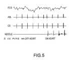
- FIG. 5is a chart showing a sample bipolar ECG recording from a needle in accordance with the present teachings.
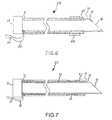
- FIG. 6is a cross-sectional view of a third needle in accordance with the present teachings.
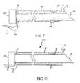
- FIG. 7is a cross-sectional view of a fourth needle in accordance with the present teachings.
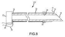
- FIGS. 8-9are cross-sectional views of a fifth needle in accordance with the present teachings.
- FIG. 10is a cross-sectional view of a sixth needle in accordance with the present teachings.
- the needle used to enter the pericardial spacemay be the same needle that is used to enter the epidural space when administering epidural anesthesia.
- the needle conventionally used for pericardial accessis a Tuohy needle.
- a Tuohy needlemay have a shaft that is generally curved for at least a portion of its length and defines a lumen. It may have a stylet within the lumen and may be blunt-tipped.
- the shaftmay comprise stainless steel.
- the shaftmay be between about 89 and 125 mm in length and approximately 1.5 mm in outer diameter.
- a first needle 10 in accordance with the present teachingsmay be similar to a Tuohy needle.
- the shaft of needle 10may be hollow with an opening 11 at a distal end.
- the shaft of the needlemay therefore define a lumen.
- a lumenmay be provided because the needle 10 may be used to access the pericardial space, and various fluids (e.g., saline, contrast agents, and medicaments) or tools may be passed through the lumen of the needle 10 into the pericardial space.
- a guidewiremay be passed through the needle 10 into the pericardial space.
- An ablation cathetermay be introduced (e.g., passed over the guidewire through the introducer lumen) into the pericardial space. The catheter may then maneuver on the epicardial surface for diagnostic and therapeutic procedures.
- a three-dimensional mapping and localization systemmay be used to map various anatomical structures, including the heart, and the position of the needle used for obtaining pericardial access.
- the mapping and localization systemmay be configured to display, for example, the relative position of the needle with respect to a heart wall.
- the systemmay use a voltage measurement of the electrode (e.g., conductive needle) in the three-dimensional electrical field of the system.
- a bare needle shaftmay distort the electrical signal by shorting the electrical field.
- the effectmay cause needle location errors and may show the midpoint of the needle in the system's map (i.e., an average position of the whole needle shaft, rather than the tip). Accordingly, it is desired to have a needle that facilitates accurate localization of the needle tip in a localization and mapping system.
- the needle 10may comprise a shaft 12 .
- the shaft 12may have an inner surface and an outer surface.
- the shaft 12may comprise a distal section 14 and a proximal section 16 .
- the distal section 14may have a conductive tip 18 .
- the tip 18may be configured to be a first electrode for voltage measurement.
- the proximal section 16may be proximate to a hub 20 .
- the hub 20may comprise, for example, a rigid epidural needle connector.
- the hub 20may be integral with the shaft 12 or may be a physically separate part which is attachable to the shaft 12 .
- the needle 10may further comprise an outer layer 22 .
- the outer layer 22may be provided to yield more accurate mapping of the tip 18 of the needle 10 in three-dimensional anatomical mapping and localization systems to facilitate the puncture process and to reduce risk during pericardial access.
- the layer 22may be disposed over a portion of the outer surface of the shaft 12 .
- a portion of the outer surface of the shaft 12 at the distal section 14may be exposed.
- the tip 18may be exposed in an embodiment. In an embodiment, approximately 1-4 mm of the distal section 14 may be exposed. A greater or smaller portion of the outer surface of the shaft 12 may be exposed and remain within the invention.
- the layer 22may comprise an electrically insulative material.
- the layer 22may comprise polymer tubing such as polytetrafluoroethylene (PTFE) heat shrink tubing.
- the layer 22may be about one ten thousandth (0.0001) of an inch in thickness.
- the layer 22may comprise a diamond-like carbon (DLC) coating.
- the layer 22may be approximately 3-5 microns in thickness.
- the layer 22may be a generally thin layer to avoid compromising needle performance.
- the layer 22may also comprise a dipped coating or a gas-vapor-deposited coating.
- the layer 22may also be scratch-resistant and biocompatible in an embodiment.
- the proximal section 16 of the shaft 12may include a connector 24 (e.g., a lead wire) to connect (e.g., operatively couple) the needle 10 to a three-dimensional anatomical mapping and localization system.
- the connector 24may be connected (e.g., securely attached) to the needle 10 in any manner conventional in the art (e.g., soldering, welding, and/or crimping). Because the shaft 12 is conductive, the connector 24 located at the proximal section 16 of the shaft 12 may connect (e.g., operatively couple) the exposed distal tip 18 of the needle 10 to the three-dimensional anatomical mapping and localization system.
- the insulated shaft 12 of the needle 10may avoid distortion of the measurement voltage field of the three-dimensional anatomical mapping and localization system.
- the voltagemay be measured at the exposed distal section 14 (e.g., tip 18 ) and may be mapped more accurately in the three-dimensional anatomical mapping and localization system as a point electrode.
- the accuracy of the three-dimensional anatomical mapping and localization systemdepends on the size of the electrode.
- a smaller electrodee.g., the exposed tip 18 of the needle 10 serving as a point electrode
- the distal section 14 (e.g., tip 18 ) of the needle 10may be located with the three-dimensional anatomical mapping and localization system as a point electrode. Physicians may therefore be able to judge the relative position of the distal section 14 (e.g., tip 18 ) of the needle 10 relative to ventricular or atrial structure based on the endocardial structure built into the EP procedure. Physicians may, therefore, avoid unintended ventricular puncture based on monitoring the proximity of the distal section 14 (e.g., tip 18 ) of the needle 10 to the endocardial surface.
- the shaft 12 of the needle 110may be substantially identical to the shaft 12 of the needle 10 .
- the needle 110may include an inner layer 26 disposed over a portion of the inner surface of the shaft 12 .
- the needle 110may include both the outer layer 22 disposed over a portion of the outer surface of the shaft 12 and the inner layer 26 disposed over a portion of the inner surface of the shaft 12 .
- the layer 26may comprise the same material and, for some embodiments, may be substantially the same thickness as the layer 22 described above. In some embodiments, the layer 26 may extend substantially the same length as the layer 22 described above.
- the material, thickness, and/or length of the layer 26may be different from the thickness and/or length of the layer 22 .
- the inner surface (e.g., tube) of the needle 10 , 110may have an effect on the electrical field and voltage measurement in three-dimensional anatomical mapping and localization systems.
- the layers 22 and 26may provide better insulation and reduce the needle effect on the electrical field and voltage measurement in a three-dimensional anatomical mapping and localization system.
- a system for determining the location of a needle during a medical proceduremay comprise the needle 10 , 110 and an anatomical mapping and localization system electrically coupled to the needle 10 , 110 and adapted to measure voltage at the conductive tip 18 .
- the needles 10 , 110may also be used to monitor an electrocardiogram (“ECG”) generated by an electrocardiograph.
- ECGelectrocardiogram
- the ECGmay include epicardial or endocardial contact through a localized catheter.
- the needles 10 , 110may be used both to monitor ECG signals and to provide information with respect to a three-dimensional anatomical mapping and localization system.
- physiciansmay obtain additional information, including confirmation that the needle has entered the pericardial sac, information regarding the thickness of the heart at the external surface (e.g., to know how long to ablate), electrical information for the heart, additional information relating to the anatomy of the heart, and information regarding the distance of the needle from the heart.
- a system for determining tissue thickness during a medical proceduremay comprise the needle 10 , 110 , an anatomical mapping and localization system electrically coupled to the needle 10 , 110 and adapted to measure voltage at the conductive tip 18 , and an electrocardiograph operatively coupled to the needle 10 , 110 and adapted to monitor electrical activity at the conductive tip 18 .
- FIG. 5illustrates a sample bipolar ECG recording from the needle 10 , 110 when the needle is about 5 to 10 mm away from the heart and when needle is in contact with the heart (see, e.g., the lowest trace in FIG. 5 ).
- the bipolar ECG recordingmay be used to convey information regarding the distance of the needle 10 , 110 from the heart.
- the shaft 12 of the needle 210may be substantially identical to the shaft 12 of the needle 10 or to the shaft 12 of the needle 110 .
- the needle 210may include only the outer layer 22 disposed over a portion of the outer surface of the shaft 12 (see needle 10 of FIGS. 1 and 3 ).
- the needle 210may include both the outer layer 22 disposed over a portion of the outer surface of the shaft 12 and the inner layer 26 disposed over a portion of the inner surface of the shaft 12 (see needle 110 of FIG. 4 ).
- the needle 210may further include a second electrode 28 for bipolar ECG monitoring and measurement. The second electrode 28 may be disposed along the shaft 12 .
- the second electrode 28may be separate from or external to the shaft 12 in an embodiment, whereas the first electrode may be the exposed distal section 14 of the shaft 12 in an embodiment.
- the second electrode 28may be disposed externally of the layer 22 and may be approximately 1-4 mm (e.g., preferably 2 mm) away from the exposed distal section 14 of the shaft 12 in an embodiment.
- the second electrode 28may generally comprise most conventional electrodes known in the art.
- the second electrode 28may comprise a regular 1 mm Pt/Ir electrode (i.e., Platinum/Iridium electrode).
- the electrode 28may comprise stainless steel.
- the second electrode 28may comprise a ring, mesh, fabric, or braid disposed around the needle 210 .
- a second connector 30(e.g., a lead wire) may extend from the second electrode 28 for connection (e.g., operative coupling) to a three-dimensional anatomical mapping and localization system.
- the second connector 30may be connected (e.g., securely attached) to the second electrode 28 in any manner conventional in the art.
- the outer layer 22may define a lumen or recess (not shown) that extends proximally the length of the outer layer 22 (e.g., a longitudinally-extending recess or a longitudinally-extending annular channel).
- the lumen or recessmay house the second connector 30 as it extends from the second electrode 28 toward the proximal section 16 of the shaft 12 .
- the second connector 30may further extend from near the proximal section 16 of the shaft 12 to a three-dimensional anatomical mapping and localization system.
- the use of the second electrode 30may further allow physicians to more accurately determine the location of the distal section 14 (e.g., the tip 18 ) of the needle 210 relative to the various structures of the heart and facilitate the puncture process and reduce risks during pericardial access (e.g., puncture of the heart chamber).
- the second electrode 28 and the exposed distal section 14 (e.g., the tip 18 ) of the needle 210may form a bipolar pair.
- the second electrode 28 and the exposed distal section 14 (e.g., the tip 18 ) of the needle 210may be mapped in a three-dimensional anatomical mapping and localization system separately so that the orientation of the needle 210 may be displayed.
- Bipolar ECGcan be monitored from the two electrodes (e.g., the second electrode 28 and the point electrode at the exposed distal section 14 of the shaft 12 ) to improve the efficacy and safety of the puncture.
- the differential bipolar ECGminimizes the far field signal and represents the local electrical activity in the myocardium.
- bipolar ECGa proximity indicator to help determine if the needle 210 is in contact with the heart and to thereby avoid unintended puncture through the heart wall.
- the bipolar ECG associated with the needleis minimal (see, e.g., the lowest trace in FIG. 5 ) because there is no local cardiac activity.
- the bipolar signalincreases significantly when the needle 210 contacts the heart (see, e.g., FIG. 5 ).
- physiciansmay be cautious to move the needle 210 forward when a high amplitude bipolar signal is observed.
- the bipolar ECG signalcan further indicate the location of the needle 210 on the heart so that physicians can puncture at an appropriate location.
- additional catheters in the heartsuch as a CS catheter (i.e., coronary sinus catheter) or HIS catheter (i.e., HIS bundle catheter)
- physiciansmay determine the location of the needle 10 based on the relationship of the sensed ECG signals to the location of the additional catheters. Physicians can thereby select an appropriate location to puncture so that further procedures, including catheter deployment, may be safer and more efficient.
- the shaft 12 of the needle 310may be substantially identical to the shaft 12 of the needle 210 .
- the needle 310may further comprise an intermediate layer 32 .
- the outer layer 22may be disposed over a portion of the outward-most surface of the intermediate layer 32 .
- the outer layer 22may also be disposed over a portion of the second electrode 28 . Accordingly, in an embodiment, a portion of the second electrode 28 may be exposed, and a portion of the second electrode 28 may be covered by the outer layer 22 . In this embodiment, the outer layer 22 may thereby help to fix the position of the electrode 28 on the shaft 12 .
- the intermediate layer 32may comprise the same material and, for some embodiments, may be substantially the same thickness as the outer layer 22 and/or the inner layer 26 described above.
- the intermediate layer 32may extend substantially the same length as the outer layer 22 and/or the inner layer 26 described above.
- the material, thickness, and/or length of the intermediate layer 32may be different from the material, thickness, and/or length of the outer layer 22 and/or the inner layer 26 .
- the second connector 30may be connected (e.g., securely attached) to the second electrode 28 in any manner conventional in the art.
- the outer layer 22 or the intermediate layer 32may define a lumen or recess (not shown) that extends proximally the length of the outer layer 22 (e.g., a longitudinally-extending recess or a longitudinally-extending annular channel).
- This lumenmay house the second connector 30 as it extends from the second electrode 28 toward the proximal section 16 of the shaft 12 .
- the second connector 30may further extend from near the proximal section 16 of the shaft 12 to a three-dimensional anatomical mapping and localization system.
- the shaft 12 of the needle 410may be substantially identical to the shaft 12 of the needle 210 .
- the needle 410may further comprise a recess 34 on the outer surface of the shaft 12 .
- the recess 34may comprise an annular recess, and the recess 34 may be configured to receive the second electrode 28 .
- the second electrode 28may be slightly embedded into the outer surface of the outer layer 22 .
- the second electrode 28may be embedded further into or fully through the outer layer 22 so as to partially or fully reside in the recess 34 .
- the recess 34may provide for a smoother outer surface on the needle 410 after the second electrode 28 is disposed over the shaft 12 than the outer surface of the needle 410 as depicted in FIG. 8 since a greater portion of the second electrode 28 may be disposed in the recess 34 and only the remainder of the second electrode 28 may project above the outer layer 22 .
- a smooth surfacemay facilitate puncture by the needle 410 during an EP procedure and may reduce the risk of adverse effects such as blood coagulation.
- the shaft 12 of the needle 510may be substantially identical to the shaft 12 of the needle 210 .
- the needle 510may further comprise a recess 36 on the outer surface of the outer layer 22 .
- the recess 36may comprise an annular recess, and the recess 36 may be configured to receive the second electrode 28 .
- the outer surface of the needle 510may be even smoother than the outer surface of the needle 410 as depicted in FIG. 8 or 9 .
- the recess 36may be configured in size and shape so that when the recess 36 receives the second electrode 28 , the outer surface of the second electrode 28 is substantially flush with the outer surface of the outer layer 22 .
- a smooth surfacemay facilitate puncture by the needle 510 during an EP procedure and may reduce the risk of adverse effects such as blood coagulation.
- fewer or more electrodescould be included on the needle 10 , 110 , 210 , 310 , 410 , 510 .
- two or more separate electrodescould be attached to the needle 10 , 110 , 210 , 310 , 410 , 510 .
- Two separate electrodeswould allow for monitoring multiple bipolar ECG signals, instead of one separate electrode and the exposed distal section 14 of the needle 10 , 110 , 210 , 310 , 410 , 510 forming a single bipolar pair. More bipolar ECGs can be monitored by including more electrodes on the shaft 12 of the needle.
- joinder referencesdo not necessarily infer that two elements are directly connected and in fixed relation to each other. It is intended that all matter contained in the above description or shown in the accompanying drawings shall be interpreted as illustrative only and not limiting. Changes in detail or structure may be made without departing from the invention as defined in the appended claims.
Landscapes
- Health & Medical Sciences (AREA)
- Surgery (AREA)
- Life Sciences & Earth Sciences (AREA)
- Biomedical Technology (AREA)
- Nuclear Medicine, Radiotherapy & Molecular Imaging (AREA)
- Engineering & Computer Science (AREA)
- Pathology (AREA)
- Heart & Thoracic Surgery (AREA)
- Medical Informatics (AREA)
- Molecular Biology (AREA)
- Animal Behavior & Ethology (AREA)
- General Health & Medical Sciences (AREA)
- Public Health (AREA)
- Veterinary Medicine (AREA)
- Measurement And Recording Of Electrical Phenomena And Electrical Characteristics Of The Living Body (AREA)
Abstract
Description
Claims (18)
Priority Applications (1)
| Application Number | Priority Date | Filing Date | Title |
|---|---|---|---|
| US11/967,518US8255035B2 (en) | 2007-12-31 | 2007-12-31 | Coated hypodermic needle |
Applications Claiming Priority (1)
| Application Number | Priority Date | Filing Date | Title |
|---|---|---|---|
| US11/967,518US8255035B2 (en) | 2007-12-31 | 2007-12-31 | Coated hypodermic needle |
Publications (2)
| Publication Number | Publication Date |
|---|---|
| US20090171304A1 US20090171304A1 (en) | 2009-07-02 |
| US8255035B2true US8255035B2 (en) | 2012-08-28 |
Family
ID=40799389
Family Applications (1)
| Application Number | Title | Priority Date | Filing Date |
|---|---|---|---|
| US11/967,518Expired - Fee RelatedUS8255035B2 (en) | 2007-12-31 | 2007-12-31 | Coated hypodermic needle |
Country Status (1)
| Country | Link |
|---|---|
| US (1) | US8255035B2 (en) |
Cited By (30)
| Publication number | Priority date | Publication date | Assignee | Title |
|---|---|---|---|---|
| US8781555B2 (en) | 2007-11-26 | 2014-07-15 | C. R. Bard, Inc. | System for placement of a catheter including a signal-generating stylet |
| US8784336B2 (en) | 2005-08-24 | 2014-07-22 | C. R. Bard, Inc. | Stylet apparatuses and methods of manufacture |
| US8849382B2 (en) | 2007-11-26 | 2014-09-30 | C. R. Bard, Inc. | Apparatus and display methods relating to intravascular placement of a catheter |
| US8858455B2 (en) | 2006-10-23 | 2014-10-14 | Bard Access Systems, Inc. | Method of locating the tip of a central venous catheter |
| US9125578B2 (en) | 2009-06-12 | 2015-09-08 | Bard Access Systems, Inc. | Apparatus and method for catheter navigation and tip location |
| US9265443B2 (en) | 2006-10-23 | 2016-02-23 | Bard Access Systems, Inc. | Method of locating the tip of a central venous catheter |
| US9339206B2 (en) | 2009-06-12 | 2016-05-17 | Bard Access Systems, Inc. | Adaptor for endovascular electrocardiography |
| US9415188B2 (en) | 2010-10-29 | 2016-08-16 | C. R. Bard, Inc. | Bioimpedance-assisted placement of a medical device |
| US9445734B2 (en) | 2009-06-12 | 2016-09-20 | Bard Access Systems, Inc. | Devices and methods for endovascular electrography |
| US9456766B2 (en) | 2007-11-26 | 2016-10-04 | C. R. Bard, Inc. | Apparatus for use with needle insertion guidance system |
| US9492097B2 (en) | 2007-11-26 | 2016-11-15 | C. R. Bard, Inc. | Needle length determination and calibration for insertion guidance system |
| US9521961B2 (en) | 2007-11-26 | 2016-12-20 | C. R. Bard, Inc. | Systems and methods for guiding a medical instrument |
| US9532724B2 (en) | 2009-06-12 | 2017-01-03 | Bard Access Systems, Inc. | Apparatus and method for catheter navigation using endovascular energy mapping |
| US9554716B2 (en) | 2007-11-26 | 2017-01-31 | C. R. Bard, Inc. | Insertion guidance system for needles and medical components |
| US9636031B2 (en) | 2007-11-26 | 2017-05-02 | C.R. Bard, Inc. | Stylets for use with apparatus for intravascular placement of a catheter |
| US9649048B2 (en) | 2007-11-26 | 2017-05-16 | C. R. Bard, Inc. | Systems and methods for breaching a sterile field for intravascular placement of a catheter |
| US9681823B2 (en) | 2007-11-26 | 2017-06-20 | C. R. Bard, Inc. | Integrated system for intravascular placement of a catheter |
| US9839372B2 (en) | 2014-02-06 | 2017-12-12 | C. R. Bard, Inc. | Systems and methods for guidance and placement of an intravascular device |
| US9901714B2 (en) | 2008-08-22 | 2018-02-27 | C. R. Bard, Inc. | Catheter assembly including ECG sensor and magnetic assemblies |
| US9907513B2 (en) | 2008-10-07 | 2018-03-06 | Bard Access Systems, Inc. | Percutaneous magnetic gastrostomy |
| US10046139B2 (en) | 2010-08-20 | 2018-08-14 | C. R. Bard, Inc. | Reconfirmation of ECG-assisted catheter tip placement |
| US10349890B2 (en) | 2015-06-26 | 2019-07-16 | C. R. Bard, Inc. | Connector interface for ECG-based catheter positioning system |
| US10449330B2 (en) | 2007-11-26 | 2019-10-22 | C. R. Bard, Inc. | Magnetic element-equipped needle assemblies |
| US10524691B2 (en) | 2007-11-26 | 2020-01-07 | C. R. Bard, Inc. | Needle assembly including an aligned magnetic element |
| US10631840B2 (en) | 2015-11-25 | 2020-04-28 | Talon Medical, LLC | Tissue engagement devices, systems, and methods |
| US10751509B2 (en) | 2007-11-26 | 2020-08-25 | C. R. Bard, Inc. | Iconic representations for guidance of an indwelling medical device |
| US10973584B2 (en) | 2015-01-19 | 2021-04-13 | Bard Access Systems, Inc. | Device and method for vascular access |
| US10992079B2 (en) | 2018-10-16 | 2021-04-27 | Bard Access Systems, Inc. | Safety-equipped connection systems and methods thereof for establishing electrical connections |
| US11000207B2 (en) | 2016-01-29 | 2021-05-11 | C. R. Bard, Inc. | Multiple coil system for tracking a medical device |
| US12440238B2 (en) | 2021-09-09 | 2025-10-14 | C. R. Bard, Inc. | Apparatus for use with needle insertion guidance system |
Families Citing this family (17)
| Publication number | Priority date | Publication date | Assignee | Title |
|---|---|---|---|---|
| WO2011041489A2 (en)* | 2009-09-30 | 2011-04-07 | Mayo Foundation For Medical Education And Research | Enhanced signal navigation and capture systems and methods |
| US20110190763A1 (en)* | 2010-01-29 | 2011-08-04 | Medtronic, Inc. | Needle Design for Recording Monophasic Action Potential and Delivery of Therapy |
| JP5973882B2 (en) | 2012-11-13 | 2016-08-23 | オリンパス株式会社 | Medical device |
| GB2515493A (en)* | 2013-06-24 | 2014-12-31 | Gyrus Medical Ltd | Electrosurgical instrument |
| WO2015058096A1 (en) | 2013-10-18 | 2015-04-23 | Ziva Medical, Inc. | Methods and systems for the treatment of polycystic ovary syndrome |
| US9867963B2 (en)* | 2014-06-17 | 2018-01-16 | Avent, Inc. | Needle hub for over-the-needle catheter |
| ES2964948T3 (en) | 2015-03-31 | 2024-04-10 | May Health Us Inc | Methods and systems for the manipulation of ovarian tissues |
| CN104771209B (en)* | 2015-04-14 | 2017-03-22 | 周正兴 | V-shaped endoscopic curer for special acupuncture |
| AU2016319002B2 (en)* | 2015-09-09 | 2021-05-13 | Boston Scientific Medical Device Limited | Epicardial access system & methods |
| US20190000501A1 (en)* | 2017-07-03 | 2019-01-03 | Bryan Nowroozi | Systems, devices and methods for accessing a body |
| US11564736B2 (en)* | 2019-01-25 | 2023-01-31 | May Health Sas | Systems and methods for applying energy to ovarian tissue |
| US12262976B2 (en) | 2019-03-13 | 2025-04-01 | Blossom Innovations Llc | Devices, systems and methods for tissue analysis, location determination and therapy thereof using optical radiation |
| US11432733B2 (en)* | 2019-03-13 | 2022-09-06 | Blossom Innovations | Tissue detection devices, systems and methods |
| KR102828193B1 (en)* | 2020-03-27 | 2025-07-02 | 니혼라이프라인 가부시키가이샤 | Drug injection needles and drug injection needle systems |
| JP7373056B2 (en)* | 2020-03-27 | 2023-11-01 | 日本ライフライン株式会社 | Chemical injection needles and chemical injection needle systems |
| JP7373055B2 (en)* | 2020-03-27 | 2023-11-01 | 日本ライフライン株式会社 | Liquid injection needle system |
| US20220142668A1 (en)* | 2020-11-11 | 2022-05-12 | Fiab S.P.A. | Tubular element for medical use |
Citations (19)
| Publication number | Priority date | Publication date | Assignee | Title |
|---|---|---|---|---|
| US3313293A (en)* | 1964-01-13 | 1967-04-11 | Hewlett Packard Co | Multi-electrode needle |
| US3682162A (en)* | 1968-12-13 | 1972-08-08 | Wellcome Found | Combined electrode and hypodermic syringe needle |
| US4483338A (en)* | 1981-06-12 | 1984-11-20 | Raychem Corporation | Bi-Polar electrocautery needle |
| US5078714A (en)* | 1990-03-02 | 1992-01-07 | Jefferson Katims | Method and apparatus for placement of a probe in the body and the medical procedure for guiding and locating a catheter or probe in the body |
| US5403311A (en) | 1993-03-29 | 1995-04-04 | Boston Scientific Corporation | Electro-coagulation and ablation and other electrotherapeutic treatments of body tissue |
| US5405376A (en) | 1993-08-27 | 1995-04-11 | Medtronic, Inc. | Method and apparatus for ablation |
| US5431649A (en) | 1993-08-27 | 1995-07-11 | Medtronic, Inc. | Method and apparatus for R-F ablation |
| US5609151A (en) | 1994-09-08 | 1997-03-11 | Medtronic, Inc. | Method for R-F ablation |
| US5656029A (en)* | 1992-12-01 | 1997-08-12 | Cardiac Pathways Corporation | Steerable catheter with adjustable bend location and/or radius and method |
| US5807395A (en) | 1993-08-27 | 1998-09-15 | Medtronic, Inc. | Method and apparatus for RF ablation and hyperthermia |
| US5928159A (en)* | 1995-03-03 | 1999-07-27 | Neothermia Corporation | Apparatus and method for characterization and treatment of tumors |
| US5976110A (en) | 1998-01-14 | 1999-11-02 | Duke University | Catheter system for administration of continuous peripheral nerve anesthetic |
| US6002956A (en)* | 1995-05-23 | 1999-12-14 | Cardima, Inc. | Method of treating using an over-the-wire EP catheter |
| US6298256B1 (en)* | 1999-09-10 | 2001-10-02 | Frank-Egbert Meyer | Device and method for the location and catheterization of the surroundings of a nerve |
| US20020169371A1 (en)* | 2001-04-20 | 2002-11-14 | Gilderdale David J. | Surgical probe |
| US20040193152A1 (en)* | 2003-03-28 | 2004-09-30 | Jeffrey Sutton | Windowed thermal ablation probe |
| US20040260241A1 (en)* | 2003-03-26 | 2004-12-23 | Terumo Kabushiki Kaisha | Catheter with puncture sensor |
| US20050267467A1 (en) | 2004-01-16 | 2005-12-01 | Saurav Paul | Bipolar conforming electrode catheter and methods for ablation |
| US20070005053A1 (en) | 2005-06-30 | 2007-01-04 | Dando Jeremy D | Ablation catheter with contoured openings in insulated electrodes |
- 2007
- 2007-12-31USUS11/967,518patent/US8255035B2/ennot_activeExpired - Fee Related
Patent Citations (20)
| Publication number | Priority date | Publication date | Assignee | Title |
|---|---|---|---|---|
| US3313293A (en)* | 1964-01-13 | 1967-04-11 | Hewlett Packard Co | Multi-electrode needle |
| US3682162A (en)* | 1968-12-13 | 1972-08-08 | Wellcome Found | Combined electrode and hypodermic syringe needle |
| US4483338A (en)* | 1981-06-12 | 1984-11-20 | Raychem Corporation | Bi-Polar electrocautery needle |
| US5078714A (en)* | 1990-03-02 | 1992-01-07 | Jefferson Katims | Method and apparatus for placement of a probe in the body and the medical procedure for guiding and locating a catheter or probe in the body |
| US5656029A (en)* | 1992-12-01 | 1997-08-12 | Cardiac Pathways Corporation | Steerable catheter with adjustable bend location and/or radius and method |
| US5403311A (en) | 1993-03-29 | 1995-04-04 | Boston Scientific Corporation | Electro-coagulation and ablation and other electrotherapeutic treatments of body tissue |
| US5807395A (en) | 1993-08-27 | 1998-09-15 | Medtronic, Inc. | Method and apparatus for RF ablation and hyperthermia |
| US5431649A (en) | 1993-08-27 | 1995-07-11 | Medtronic, Inc. | Method and apparatus for R-F ablation |
| US5405376A (en) | 1993-08-27 | 1995-04-11 | Medtronic, Inc. | Method and apparatus for ablation |
| US5609151A (en) | 1994-09-08 | 1997-03-11 | Medtronic, Inc. | Method for R-F ablation |
| US5725524A (en) | 1994-09-08 | 1998-03-10 | Medtronic, Inc. | Apparatus for R-F ablation |
| US5928159A (en)* | 1995-03-03 | 1999-07-27 | Neothermia Corporation | Apparatus and method for characterization and treatment of tumors |
| US6002956A (en)* | 1995-05-23 | 1999-12-14 | Cardima, Inc. | Method of treating using an over-the-wire EP catheter |
| US5976110A (en) | 1998-01-14 | 1999-11-02 | Duke University | Catheter system for administration of continuous peripheral nerve anesthetic |
| US6298256B1 (en)* | 1999-09-10 | 2001-10-02 | Frank-Egbert Meyer | Device and method for the location and catheterization of the surroundings of a nerve |
| US20020169371A1 (en)* | 2001-04-20 | 2002-11-14 | Gilderdale David J. | Surgical probe |
| US20040260241A1 (en)* | 2003-03-26 | 2004-12-23 | Terumo Kabushiki Kaisha | Catheter with puncture sensor |
| US20040193152A1 (en)* | 2003-03-28 | 2004-09-30 | Jeffrey Sutton | Windowed thermal ablation probe |
| US20050267467A1 (en) | 2004-01-16 | 2005-12-01 | Saurav Paul | Bipolar conforming electrode catheter and methods for ablation |
| US20070005053A1 (en) | 2005-06-30 | 2007-01-04 | Dando Jeremy D | Ablation catheter with contoured openings in insulated electrodes |
Non-Patent Citations (2)
| Title |
|---|
| www.wikipedia.org/wiki/Tuohy-needle. |
| www.wikipedia.org/wiki/Tuohy—needle. |
Cited By (61)
| Publication number | Priority date | Publication date | Assignee | Title |
|---|---|---|---|---|
| US8784336B2 (en) | 2005-08-24 | 2014-07-22 | C. R. Bard, Inc. | Stylet apparatuses and methods of manufacture |
| US11207496B2 (en) | 2005-08-24 | 2021-12-28 | C. R. Bard, Inc. | Stylet apparatuses and methods of manufacture |
| US10004875B2 (en) | 2005-08-24 | 2018-06-26 | C. R. Bard, Inc. | Stylet apparatuses and methods of manufacture |
| US9345422B2 (en) | 2006-10-23 | 2016-05-24 | Bard Acess Systems, Inc. | Method of locating the tip of a central venous catheter |
| US8858455B2 (en) | 2006-10-23 | 2014-10-14 | Bard Access Systems, Inc. | Method of locating the tip of a central venous catheter |
| US9265443B2 (en) | 2006-10-23 | 2016-02-23 | Bard Access Systems, Inc. | Method of locating the tip of a central venous catheter |
| US9833169B2 (en) | 2006-10-23 | 2017-12-05 | Bard Access Systems, Inc. | Method of locating the tip of a central venous catheter |
| US10238418B2 (en) | 2007-11-26 | 2019-03-26 | C. R. Bard, Inc. | Apparatus for use with needle insertion guidance system |
| US11123099B2 (en) | 2007-11-26 | 2021-09-21 | C. R. Bard, Inc. | Apparatus for use with needle insertion guidance system |
| US12295714B2 (en) | 2007-11-26 | 2025-05-13 | C. R. Bard, Inc. | Needle assembly including an aligned magnetic element |
| US9456766B2 (en) | 2007-11-26 | 2016-10-04 | C. R. Bard, Inc. | Apparatus for use with needle insertion guidance system |
| US9492097B2 (en) | 2007-11-26 | 2016-11-15 | C. R. Bard, Inc. | Needle length determination and calibration for insertion guidance system |
| US9521961B2 (en) | 2007-11-26 | 2016-12-20 | C. R. Bard, Inc. | Systems and methods for guiding a medical instrument |
| US9526440B2 (en) | 2007-11-26 | 2016-12-27 | C.R. Bard, Inc. | System for placement of a catheter including a signal-generating stylet |
| US11779240B2 (en) | 2007-11-26 | 2023-10-10 | C. R. Bard, Inc. | Systems and methods for breaching a sterile field for intravascular placement of a catheter |
| US9549685B2 (en) | 2007-11-26 | 2017-01-24 | C. R. Bard, Inc. | Apparatus and display methods relating to intravascular placement of a catheter |
| US9554716B2 (en) | 2007-11-26 | 2017-01-31 | C. R. Bard, Inc. | Insertion guidance system for needles and medical components |
| US9636031B2 (en) | 2007-11-26 | 2017-05-02 | C.R. Bard, Inc. | Stylets for use with apparatus for intravascular placement of a catheter |
| US9649048B2 (en) | 2007-11-26 | 2017-05-16 | C. R. Bard, Inc. | Systems and methods for breaching a sterile field for intravascular placement of a catheter |
| US9681823B2 (en) | 2007-11-26 | 2017-06-20 | C. R. Bard, Inc. | Integrated system for intravascular placement of a catheter |
| US11707205B2 (en) | 2007-11-26 | 2023-07-25 | C. R. Bard, Inc. | Integrated system for intravascular placement of a catheter |
| US11529070B2 (en) | 2007-11-26 | 2022-12-20 | C. R. Bard, Inc. | System and methods for guiding a medical instrument |
| US10602958B2 (en) | 2007-11-26 | 2020-03-31 | C. R. Bard, Inc. | Systems and methods for guiding a medical instrument |
| US10524691B2 (en) | 2007-11-26 | 2020-01-07 | C. R. Bard, Inc. | Needle assembly including an aligned magnetic element |
| US9999371B2 (en) | 2007-11-26 | 2018-06-19 | C. R. Bard, Inc. | Integrated system for intravascular placement of a catheter |
| US8849382B2 (en) | 2007-11-26 | 2014-09-30 | C. R. Bard, Inc. | Apparatus and display methods relating to intravascular placement of a catheter |
| US11134915B2 (en) | 2007-11-26 | 2021-10-05 | C. R. Bard, Inc. | System for placement of a catheter including a signal-generating stylet |
| US10105121B2 (en) | 2007-11-26 | 2018-10-23 | C. R. Bard, Inc. | System for placement of a catheter including a signal-generating stylet |
| US10165962B2 (en) | 2007-11-26 | 2019-01-01 | C. R. Bard, Inc. | Integrated systems for intravascular placement of a catheter |
| US10751509B2 (en) | 2007-11-26 | 2020-08-25 | C. R. Bard, Inc. | Iconic representations for guidance of an indwelling medical device |
| US10231753B2 (en) | 2007-11-26 | 2019-03-19 | C. R. Bard, Inc. | Insertion guidance system for needles and medical components |
| US8781555B2 (en) | 2007-11-26 | 2014-07-15 | C. R. Bard, Inc. | System for placement of a catheter including a signal-generating stylet |
| US10449330B2 (en) | 2007-11-26 | 2019-10-22 | C. R. Bard, Inc. | Magnetic element-equipped needle assemblies |
| US10342575B2 (en) | 2007-11-26 | 2019-07-09 | C. R. Bard, Inc. | Apparatus for use with needle insertion guidance system |
| US10966630B2 (en) | 2007-11-26 | 2021-04-06 | C. R. Bard, Inc. | Integrated system for intravascular placement of a catheter |
| US10849695B2 (en) | 2007-11-26 | 2020-12-01 | C. R. Bard, Inc. | Systems and methods for breaching a sterile field for intravascular placement of a catheter |
| US11027101B2 (en) | 2008-08-22 | 2021-06-08 | C. R. Bard, Inc. | Catheter assembly including ECG sensor and magnetic assemblies |
| US9901714B2 (en) | 2008-08-22 | 2018-02-27 | C. R. Bard, Inc. | Catheter assembly including ECG sensor and magnetic assemblies |
| US9907513B2 (en) | 2008-10-07 | 2018-03-06 | Bard Access Systems, Inc. | Percutaneous magnetic gastrostomy |
| US10349857B2 (en) | 2009-06-12 | 2019-07-16 | Bard Access Systems, Inc. | Devices and methods for endovascular electrography |
| US9125578B2 (en) | 2009-06-12 | 2015-09-08 | Bard Access Systems, Inc. | Apparatus and method for catheter navigation and tip location |
| US10912488B2 (en) | 2009-06-12 | 2021-02-09 | Bard Access Systems, Inc. | Apparatus and method for catheter navigation and tip location |
| US9445734B2 (en) | 2009-06-12 | 2016-09-20 | Bard Access Systems, Inc. | Devices and methods for endovascular electrography |
| US9532724B2 (en) | 2009-06-12 | 2017-01-03 | Bard Access Systems, Inc. | Apparatus and method for catheter navigation using endovascular energy mapping |
| US9339206B2 (en) | 2009-06-12 | 2016-05-17 | Bard Access Systems, Inc. | Adaptor for endovascular electrocardiography |
| US10271762B2 (en) | 2009-06-12 | 2019-04-30 | Bard Access Systems, Inc. | Apparatus and method for catheter navigation using endovascular energy mapping |
| US11419517B2 (en) | 2009-06-12 | 2022-08-23 | Bard Access Systems, Inc. | Apparatus and method for catheter navigation using endovascular energy mapping |
| US10231643B2 (en) | 2009-06-12 | 2019-03-19 | Bard Access Systems, Inc. | Apparatus and method for catheter navigation and tip location |
| US10046139B2 (en) | 2010-08-20 | 2018-08-14 | C. R. Bard, Inc. | Reconfirmation of ECG-assisted catheter tip placement |
| US9415188B2 (en) | 2010-10-29 | 2016-08-16 | C. R. Bard, Inc. | Bioimpedance-assisted placement of a medical device |
| US10863920B2 (en) | 2014-02-06 | 2020-12-15 | C. R. Bard, Inc. | Systems and methods for guidance and placement of an intravascular device |
| US9839372B2 (en) | 2014-02-06 | 2017-12-12 | C. R. Bard, Inc. | Systems and methods for guidance and placement of an intravascular device |
| US10973584B2 (en) | 2015-01-19 | 2021-04-13 | Bard Access Systems, Inc. | Device and method for vascular access |
| US11026630B2 (en) | 2015-06-26 | 2021-06-08 | C. R. Bard, Inc. | Connector interface for ECG-based catheter positioning system |
| US10349890B2 (en) | 2015-06-26 | 2019-07-16 | C. R. Bard, Inc. | Connector interface for ECG-based catheter positioning system |
| US11627951B2 (en) | 2015-11-25 | 2023-04-18 | Circa Scientific, Inc. | Tissue engagement devices, systems, and methods |
| US10631840B2 (en) | 2015-11-25 | 2020-04-28 | Talon Medical, LLC | Tissue engagement devices, systems, and methods |
| US11000207B2 (en) | 2016-01-29 | 2021-05-11 | C. R. Bard, Inc. | Multiple coil system for tracking a medical device |
| US11621518B2 (en) | 2018-10-16 | 2023-04-04 | Bard Access Systems, Inc. | Safety-equipped connection systems and methods thereof for establishing electrical connections |
| US10992079B2 (en) | 2018-10-16 | 2021-04-27 | Bard Access Systems, Inc. | Safety-equipped connection systems and methods thereof for establishing electrical connections |
| US12440238B2 (en) | 2021-09-09 | 2025-10-14 | C. R. Bard, Inc. | Apparatus for use with needle insertion guidance system |
Also Published As
| Publication number | Publication date |
|---|---|
| US20090171304A1 (en) | 2009-07-02 |
Similar Documents
| Publication | Publication Date | Title |
|---|---|---|
| US8255035B2 (en) | Coated hypodermic needle | |
| US10172536B2 (en) | Real-time feedback for electrode contact during mapping | |
| EP4218579B1 (en) | Intraluminal reference electrode for cardiovascular treatment apparatus | |
| KR100857038B1 (en) | Bipolar mapping of intracardiac potentials | |
| US9125573B2 (en) | Electrically transparent introducer sheath | |
| EP3790484B1 (en) | Intravascular catheter tip electrode assemblies | |
| US20110112396A1 (en) | System and method for targeting catheter electrodes | |
| JP2015506234A (en) | Electrophysiology system | |
| CN106308790A (en) | Catheter having closed electrode assembly with spines of uniform length | |
| US20200129086A1 (en) | Sensing System for Pericardial Access | |
| EP4197472A1 (en) | Catheter end effector with laterally projecting body | |
| US20240245359A1 (en) | Catheter with insert-molded microelectrode | |
| EP3810004A1 (en) | Electrical grounding feature for irrigation fluid path in catheter assembly | |
| KR101501837B1 (en) | Multi electrode pulmonary vein circular catheter |
Legal Events
| Date | Code | Title | Description |
|---|---|---|---|
| AS | Assignment | Owner name:ST. JUDE MEDICAL, ATRIAL FIBRILLATION DIVISION, IN Free format text:ASSIGNMENT OF ASSIGNORS INTEREST;ASSIGNORS:CAO, HONG;PAUL, SAURAV;THAO, CHOU;REEL/FRAME:020946/0023;SIGNING DATES FROM 20080206 TO 20080314 Owner name:ST. JUDE MEDICAL, ATRIAL FIBRILLATION DIVISION, IN Free format text:ASSIGNMENT OF ASSIGNORS INTEREST;ASSIGNORS:CAO, HONG;PAUL, SAURAV;THAO, CHOU;SIGNING DATES FROM 20080206 TO 20080314;REEL/FRAME:020946/0023 | |
| ZAAA | Notice of allowance and fees due | Free format text:ORIGINAL CODE: NOA | |
| ZAAB | Notice of allowance mailed | Free format text:ORIGINAL CODE: MN/=. | |
| STCF | Information on status: patent grant | Free format text:PATENTED CASE | |
| FPAY | Fee payment | Year of fee payment:4 | |
| MAFP | Maintenance fee payment | Free format text:PAYMENT OF MAINTENANCE FEE, 8TH YEAR, LARGE ENTITY (ORIGINAL EVENT CODE: M1552); ENTITY STATUS OF PATENT OWNER: LARGE ENTITY Year of fee payment:8 | |
| FEPP | Fee payment procedure | Free format text:MAINTENANCE FEE REMINDER MAILED (ORIGINAL EVENT CODE: REM.); ENTITY STATUS OF PATENT OWNER: LARGE ENTITY | |
| LAPS | Lapse for failure to pay maintenance fees | Free format text:PATENT EXPIRED FOR FAILURE TO PAY MAINTENANCE FEES (ORIGINAL EVENT CODE: EXP.); ENTITY STATUS OF PATENT OWNER: LARGE ENTITY | |
| STCH | Information on status: patent discontinuation | Free format text:PATENT EXPIRED DUE TO NONPAYMENT OF MAINTENANCE FEES UNDER 37 CFR 1.362 | |
| FP | Lapsed due to failure to pay maintenance fee | Effective date:20240828 |