US8254847B2 - Distributed wireless communications for tactical network dominance - Google Patents
Distributed wireless communications for tactical network dominanceDownload PDFInfo
- Publication number
- US8254847B2 US8254847B2US12/103,983US10398308AUS8254847B2US 8254847 B2US8254847 B2US 8254847B2US 10398308 AUS10398308 AUS 10398308AUS 8254847 B2US8254847 B2US 8254847B2
- Authority
- US
- United States
- Prior art keywords
- radio communication
- transceivers
- providing
- tnd
- computer
- Prior art date
- Legal status (The legal status is an assumption and is not a legal conclusion. Google has not performed a legal analysis and makes no representation as to the accuracy of the status listed.)
- Expired - Fee Related, expires
Links
Images


Classifications
- H—ELECTRICITY
- H04—ELECTRIC COMMUNICATION TECHNIQUE
- H04L—TRANSMISSION OF DIGITAL INFORMATION, e.g. TELEGRAPHIC COMMUNICATION
- H04L63/00—Network architectures or network communication protocols for network security
- H04L63/30—Network architectures or network communication protocols for network security for supporting lawful interception, monitoring or retaining of communications or communication related information
- H04L63/302—Network architectures or network communication protocols for network security for supporting lawful interception, monitoring or retaining of communications or communication related information gathering intelligence information for situation awareness or reconnaissance
- H—ELECTRICITY
- H04—ELECTRIC COMMUNICATION TECHNIQUE
- H04W—WIRELESS COMMUNICATION NETWORKS
- H04W12/00—Security arrangements; Authentication; Protecting privacy or anonymity
- H04W12/02—Protecting privacy or anonymity, e.g. protecting personally identifiable information [PII]
- H—ELECTRICITY
- H04—ELECTRIC COMMUNICATION TECHNIQUE
- H04W—WIRELESS COMMUNICATION NETWORKS
- H04W12/00—Security arrangements; Authentication; Protecting privacy or anonymity
- H04W12/03—Protecting confidentiality, e.g. by encryption
- H04W12/033—Protecting confidentiality, e.g. by encryption of the user plane, e.g. user's traffic
- H—ELECTRICITY
- H04—ELECTRIC COMMUNICATION TECHNIQUE
- H04W—WIRELESS COMMUNICATION NETWORKS
- H04W12/00—Security arrangements; Authentication; Protecting privacy or anonymity
- H04W12/80—Arrangements enabling lawful interception [LI]
- H—ELECTRICITY
- H04—ELECTRIC COMMUNICATION TECHNIQUE
- H04W—WIRELESS COMMUNICATION NETWORKS
- H04W24/00—Supervisory, monitoring or testing arrangements
- H—ELECTRICITY
- H04—ELECTRIC COMMUNICATION TECHNIQUE
- H04W—WIRELESS COMMUNICATION NETWORKS
- H04W76/00—Connection management
- H04W76/10—Connection setup
- H—ELECTRICITY
- H04—ELECTRIC COMMUNICATION TECHNIQUE
- H04W—WIRELESS COMMUNICATION NETWORKS
- H04W84/00—Network topologies
- H04W84/18—Self-organising networks, e.g. ad-hoc networks or sensor networks
Definitions
- the present inventionrelates generally to wireless sensor networks, and particularly to wireless sensor networks configured to interact with the environment that they monitor.
- a wireless sensor networkcomprises spatially distributed autonomous devices using sensors to cooperatively monitor physical or environmental conditions, such as temperature, sound, vibration, pressure, motion, or pollutants, at different locations.
- the development of wireless sensor networkswas originally motivated by military applications such as battlefield surveillance. However, wireless sensor networks are now used for many civilian applications, including environment and habitat monitoring, healthcare applications, home automation, and traffic control.
- Area monitoringis a typical application of WSNs.
- the WSNis deployed over a region where some phenomenon is to be monitored.
- a large quantity of sensor nodescould be deployed over a battlefield to detect enemy intrusion.
- the sensorsdetect the event being monitored (heat, pressure, sound, light, electromagnetic field, vibration, etc)
- the eventis reported to a base station, which can take appropriate action (e.g., send a message on the internet or to a satellite).
- different objective functionsemploy different data-propagation strategies, depending on one or more predetermined parameters, such as need for real-time response, data redundancy (which is typically handled via data aggregation techniques), need for security, etc.
- WSNsare typically designed to be deployed in large numbers in various environments, including remote and hostile regions.
- Ad-hoc communicationsare employed for linking the sensors together.
- Algorithms and protocolshave been developed to address issues associated with self-configuration, information routing, lifetime maximization, robustness, and fault tolerance.
- Embodiments disclosed hereinmay be advantageous to systems employing wireless transceiver networks for surveillance, battlefield, and first-responder applications.
- the inventionis not intended to be limited to such systems, as other wireless networking applications may benefit from similar advantages.
- a wireless transceiver networkconfigured to collect radio-spectrum information and track radio signals, then actively respond to an adversary's radio network, such as by spoofing, misdirecting, corrupting, and/or jamming signals used in the adversary's radio network.
- Embodiments of the inventionprovide for a tactical network dominance (TND) system comprising a plurality of small computational devices acting as a cluster configured to perform specific computational process, such as signal processing, to be shared across nodes and/or allocated to inactive nodes.
- TDDtactical network dominance
- each of the computational devicesis configured to perform a predetermined computational process.
- each of the computational devicesis dynamically assigned a computational process to perform.
- embodiments of the inventionmay be configured to create virtual antenna arrays on the fly to adapt to specific communication needs and/or channel conditions.
- Embodiments of the inventionmay be optimized for minimum processing complexity, such as to enable suitability for real-time applications, rapid updates, low power consumption, and/or low-cost components.
- Particular embodiments of the inventionmay be configured to provide for the previously recited features and advantages and/or alternative features and advantages.
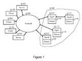
- FIG. 1shows an embodiment of a TND system of the present invention.
- FIG. 2illustrates a TND transceiver in accordance with an embodiment of the invention.
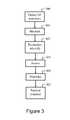
- FIG. 3illustrates a method embodiment of the invention.
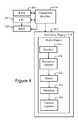
- FIG. 4is a block diagrammatic representation showing the structure of a server computer configured to execute the server in accordance with an embodiment of the invention.
- FIG. 5shows a method embodiment of the invention.
- a tactical network dominance (TND) transceivercomprises a radio receiver (e.g., a sensor) configured for detecting an external radio communication link (i.e., a radio communication link used in a radio network other than the TND network used by the TND transceiver to communicate with other TND transceivers and a central server), and a radio transmitter used for providing a non-passive tactical response to the detected radio communication link.
- the TND transceiverfurther comprises network-communication circuitry configured for transceiver functionality (i.e., transmitting and receiving data) with at least one other TND transceiver.
- the network-communication circuitryis further configured for controlling a plurality of TND transceivers, such as to coordinate reception of the external radio communication link (e.g., for performing sensing, acquisition/synchronization, diversity combining of the received signal, interference rejection, etc.).
- the network-communication circuitryis also configured for coordinating the non-passive tactical response of the plurality of TND transceivers to the detected radio communication link.
- the TND transceivermay share circuitry (such as radio and/or baseband-processing circuitry) for different transceiver operations (e.g., TND network communications and external network transceiving operations).
- the TNDmay employ separate systems or subsystems dedicated to respective transceiver operations.
- TND transceiversmay employ any combination of communications links, including (but not limited to) radio links, infra-red links, optical links, and sonic links.
- An external radio communication linkdenotes a radio communication link used in a radio network other than a network used by the TND transceiver to communicate with other TND transceivers and a central server.
- an external radio communication linkmay be identified as an external radio network employed by enemy combatants or criminals.
- a non-passive tactical responseincludes transmitting a jamming signal (a jamming signal may comprise an RF jamming signal that decreases the SNR or SINR of intended signals received by receivers employing the detected radio communication link), re-transmitting a corrupted or otherwise altered radio signal received from the detected radio communication link, transmitting a spoofed signal into the radio communication link (in this case, a spoofed signal may comprise information that falsely identifies the source of the transmitted spoofed signal), transmitting a denial-of-service (DoS) attack (e.g., a DoS attack may be intended to monopolize network resources that would otherwise be allocated to intended users of the system employing the detected radio communication link).
- TND transceiversmay utilize a network providing the detected radio communication link to enable and/or enhance communication within the TND network.
- a sensor networkcomprising a plurality of sensors configured for detecting radio emissions from an external radio network is configurable for performing antenna-array processing.
- Antenna-array processingmay include any combination of beam forming, tracking, null steering, interference cancellation, virtual array processing, and MIMO (multiple-input, multiple output) processing.
- Embodiments of the inventionmay provide for advanced receiver processing, including diversity reception, interference cancellation, MMSE equalization, and other equalization techniques.
- raw data from the sensor networkis processed by a central server configured to perform antenna-array processing.
- the sensors in the sensor networkfurther comprise computing circuitry, which is configured to share information and act as a clustered computing environment via the network-communication circuitry.
- Embodiments of the inventionmay provide for multiple clusters of sensors and/or TND transceivers, and furthermore, may provide for multi-tiered clustering, such as clusters of clusters.
- array processingmay be implemented by a plurality of the sensors. In the case where the sensors are TND transceivers, array processing may be implemented for transmitting signals to the external radio network for communications and/or for providing a non-passive tactical response.
- FIG. 1illustratively represents a simplified embodiment of a TND system 100 of the present invention.
- the system 100includes one or more servers 102 in network communication with a plurality of clients 104 .
- the simplified embodiment of FIG. 1depicts only a limited number of clients 104 and servers 102 , other embodiments may include relatively larger number of clients and servers in communication over a communication network 106 .
- the servers 102are configured to receive data streamed from one or more networks 108 of TND transceivers deployed within geographic regions of interest (e.g., a densely-populated urban center, a battlefield, or a military installation). Base stations in the TND networks may be distinguished from TND transceivers in that they possess much more computational, energy, and communication resources. The base stations act as a gateway between TND networks 108 and the servers 102 .
- Each TND transceiver network 108includes a plurality of sensors (e.g., radio receivers) 110 coupled to corresponding sensor modules or “agents” 112 .
- Each transceiver agent 112controls the relaying of data between a corresponding radio receiver 110 to one or more modules executed by a server 102 .
- the parameters of the data-relaying function effected by the transceiver agents 112may be controlled by the clients 104 .
- each transceiver agent 112is depicted as being co-located with a corresponding radio receiver 110 .
- the transceiver agents 112may be executed by the server 102 such that each is configured to receive and process “raw” data from an associated radio receiver 110 .
- TND transceiversmay be dropped, placed, or deployed over areas of tactical operation and configured to couple with systems that control and visualize information from the TND transceivers.
- Each TND transceiversearches for and identifies other TND transceivers in its immediate area and links with them to build a secure local network.
- the TND transceiversmay be further configured with computing circuitry (e.g., a microprocessor with data storage) to share information and perform computational processing as a clustered computing environment.
- TND transceiversInformation relayed between TND transceivers are generally transmitted in an encrypted form.
- an end-to-end encryptionmay be selected.
- sensed datamay be encrypted directly at a sensor node and only decrypted after receipt at a sink node.
- Security in the context of data transmission in sensor networkscan be achieved by key distributions.
- One such key distribution mechanism for pairwise secure communicationis for example described in L. Eschenauer, V. Gligor, “A key-management Scheme for Distributed Sensor Networks”, in the proceedings of 9 th ACM Conference on Computer and Communications Security (CCS'02), 41-47, November, 2002, which is hereby incorporated by reference.
- Embodiments of the inventionmay employ symmetric encryption methods, which minimizes the amount of information that can be retrieved by tampering with individual TND transceivers.
- a TND transceiver networkmay be divided into specific areas, such as routable regions.
- Embodiments of the inventionmay employ a cluster-based hierarchical routing method in which a wireless sensor network is divided into plural regions of cluster units, and a cluster is classified into cluster heads, a sink node, and sensor nodes.
- the hierarchical routing methodperforms routing via a relay node and the sink node in order to reduce overall transmit power.
- each TND transceiverencrypts their data and send it via relay-nodes (e.g., other TND transceivers), which only forward data, and/or aggregator nodes (which also may comprise TND transceivers), which aggregate the data of several TND transceivers and forward it, to the sink node.
- relay-nodese.g., other TND transceivers
- aggregator nodeswhich also may comprise TND transceivers
- An exemplary embodiment and/or exemplary method of the present inventionmay provide for energy-efficient and time-efficient exchanges of information between any two or more devices using short pulses or tones instead of packets, which may be, for example, used to supervise the devices and their connectivity status, or to synchronize the devices.
- Each client 104comprises a software module used to perform data processing, including digital signal processing and data visualization.
- the systemmay employ maps and various overlays based upon information delivered from one or more of the servers 102 . All of the relevant information can be overlaid on a map of the region of interest to facilitate the decision-making process by providing critical information in an easy-to-digest format for display.
- each client 104is created in the Microsoft.NET framework, and may be executed by conventional computer platforms within command and control centers as well as by mobile computing devices (e.g., PDAs) distributed to personnel in the geographic region of interest.
- demodulationincluding despreading and/or decoding
- the TND systemis designed to provide superior receiver sensitivity using real-time software that networks existing sensors and other radio receivers into an antenna array.
- the TND systemcontinuously and automatically scans the radio spectrum in the geographic regions of interest.
- array-processing algorithms and/or advanced receiver algorithmsmay be applied to the received data to provide triangulation or direction finding to identify the location of the signal's source. This enables immediate generation of alerts to proper authorities, agencies, or tactical groups to identify the detected radio link and the location of its users.
- Advanced receiverstypically employ a combination of LMMSE equalization (or some other form of equalization) and receive diversity.
- Advanced receivers based on receive diversityhave been studied for WCDMA and have demonstrated significant performance improvements, particularly at low SNR, such as shown in 3GPP TS 25.101 V6.8.0, “User Equipment (UE) Radio Transmission and Reception (FDD)”, June 2005, which is hereby incorporated by reference.
- UEUser Equipment
- FDDRadio Transmission and Reception
- Each client 104comprises a software module configured to perform identification of a radio communication link. For example, a radio communication system and/or user associated with the link may be determined. Some embodiments may provide for comparing spectral parameters (e.g., frequency band and/or signal bandwidth) of a received signal to a look-up table containing spectral parameters corresponding to known communication systems.
- the software modulemay determine the identity of the communication system supporting the detected radio communication link, or at least determine the type of communication system employing the detected link.
- the software modulemay employ despreading, demodulation, and/or decoding to identify the source of the link and/or users employing the link.
- the client 104may comprise a software module configured to perform array processing for tracking the location of one or more radio transmissions.
- radio transmissionsthat may be monitored include either or both adversary transmissions and transmissions originating from known, or “friendly,” users or communication networks.
- the TND systemmay transition to a network-dominance mode to allow users of the client 104 to infiltrate, corrupt, disable, spoof, or exploit communication resources of the adversary's local network infrastructure.
- the client 104may comprise a software module configured for providing an active tactical response targeting an adversary's radio communication network.
- a tactical response software modulemay comprise antenna-array processing software for directing transmissions to the adversary's radio communication network.
- array-processing softwaremay be configured to perform retro-directive array processing, such as may be based on angle-of-arrival data of received signal and/or channel estimates of the propagation environment between the TND transceiver network 108 and an adversary's radio transmitter.
- Data from one or more software modulesis coupled to each transceiver agent 112 , which controls the relaying of data to a corresponding radio transmitter 111 .
- Data from the software modulesmay include control information, such as to configure the amplitude, timing, and/or phase of signals transmitted by each radio transmitter 111 .
- FIG. 2illustrates a TND transceiver in accordance with an embodiment of the invention.
- the TND transceivertypically has an exterior shell designed to protect contained electronics from impact, moisture, dust, and optionally, other environmental and/or operational hazards that would otherwise damage or impede the function of the electronics.
- the TND transceiverusually comprises a processing unit 201 with limited computational power and limited memory, at least one radio sensor 202 (including specific conditioning circuitry), a communication device 203 (usually a radio transceiver or alternatively an optical transceiver) configured for communicating with other TND transceivers and/or a predetermined access point, and a power source 204 —usually in the form of a battery.
- Other possible inclusionsare energy harvesting modules (not shown), secondary ASICs (not shown), and possibly secondary communication devices (not shown), such as RS232 or USB devices.
- the senor 202comprises a radio-frequency (RF) receiver, such as an antenna, an RF front-end, and an analog-to-digital converter (ADC).
- the RF front-endmay be configured for performing any combination of well-known radio signal processing operations, including, but not limited to frequency down-conversion and filtering.
- a baseband processormay be provided for despreading, demodulating, decoding, and/or otherwise processing received down-converted signals.
- the processing unit 201comprises network-communication circuitry for data acquisition and communication with other TND transceivers or a base station, and computing circuitry, such as may be required for receiver processing (e.g., Rake processing, equalization, array processing, coding/decoding operations, direction finding, acquisition/synchronization, etc.).
- the computing circuitrymay be employed for identifying, allocating, and coordinating computing resources with other TND transceivers.
- the senorcomprises an RF transmitter sharing the components employed by the RF receiver. Consequently, the transmitter may comprise the baseband processor, which may be configurable for performing channel coding, modulation, spreading, and/or additional or alternative baseband signal processing operations.
- the ADCmay be configured for performing digital-to-analog conversion of a baseband signal intended for transmission.
- the RF front-endmay be configured for performing frequency up-conversion, transmit filtering, amplification, and/or additional or alternative RF front-end processing operations that are known in the art.
- the TND transceiver networks 108 and any other deployed receiversacquire data in order to detect the use of unknown radio communication networks (i.e., external radio communication links), or the presence of unknown radio communication devices.
- spectral-power thresholdsmay also be set relative to baseline levels in order to define the presence of radio transmissions.
- measurement data streamed from the TND transceiver network 108 to one or more of the servers 102may be compared against a predetermined database of radio communication networks.
- the databasemay comprise known communication networks employed by friendly forces, networks employed by neutral parties, and/or networks likely to be employed by hostile parties.
- Subsequent phasesmay be characterized as a monitor phase 301 , a recognize/identify networks phase 302 , an assessment phase 303 , a prioritization phase 304 , and a tactical-response phase 305 .
- These phaseswill generally operate in the sequence depicted in FIG. 3 with respect to measured radio-signal data acquired contemporaneously during a given time period. However, since such measurement data will typically be received by the applicable server 102 in a continuous stream, it is also the case that the respective phases will operate in parallel at any given point in time (i.e., each being engaged in processing measurement data acquired during a different time period).
- the processing effected by the applicable server 102 during the monitor phase 301involves observing and recording incoming measurement data from the sensor networks 108 and identifying changes relative to thresholds set during the previous phase 300 .
- the types of signals detected and reported during execution of the monitor phase 301will depend on the nature of the processing performed by the clients 104 and/or the TND agents 112 .
- spectral datamay be obtained via fast Fourier transform processing.
- matched filtersmay be employed to identify either or both specific time-domain energy signatures and predetermined frequency-domain energy profiles.
- the TND agents 112connect to their associated TND transceivers 110 , collect ambient sensor measurement data, and pass the raw data through the sensor network 108 to the server 102 .
- each TND agent 112may represent a virtual sensor rather than a physical sensor (e.g., during performance of a simulation), but for the sake of the present discussion, it is assumed that the TND agents 112 receive data from, and are representative of, actual TND transceiver measurements.
- the TND agents 112may stream measurement data collected by a corresponding TND transceiver 110 to the server 102 in accordance with a user-defined or default sampling frequency.
- a user-defined or default sampling frequencyFor example, when battery-operated receivers are employed, it becomes important to conserve power by, for example, minimizing the power expended to communicate measurement data from such receivers to the server 102 .
- each agent 112 associated with such a receivermay set a periodic sampling rate, buffer a number of the readings provided by the receiver, and then instruct that a batch of readings be transmitted at once in order to minimize power drain. If a reading hits a pre-defined “threshold” level, the applicable agent 112 can immediately change its behavior to increase the applicable sampling frequency and begin continuously streaming the readings to the server 102 rather than continue to buffer the readings received.
- the recognize/identify networks phase 302involves processing data only from a subset of TND transceivers that produce measurements exceeding the threshold levels set during phase 300 .
- this embodimentcorresponds to perhaps the most straightforward implementation, substantially more complex implementations of the identification process have also been contemplated and may be employed by alternative embodiments of the invention.
- implementation of the assessment phase 303may be facilitated by processing received signals to locate the direction or source of a detected transmission.
- processingmay employ angle-of-arrival algorithms, triangulation, channel estimation, and/or alternative algorithms for geographically locating one or more detected radio transmitters.
- baseband signal-processing operationsmay be performed to determine information content of the transmitted signals for intelligence gathering in order to identify users of the network and assess the threat of these users to tactical operations.
- the prioritize phase 304involves determining, in accordance with a set of predefined rules, an appropriate response to a threat identified during the preceding assessment phase 303 .
- a plurality of predefined priority valuesare established prior to initiating operation of the system 100 , and one of these is assigned during the prioritize phase 304 to each threat identified during the assessment phase 303 .
- threats which have been identified as being serious in naturecan be assigned a relatively high priority value and allocated appropriate amounts of system resources. For example, system processing priority may be given to threats that are identified as high priority.
- the visual representations provided to end users via clients 104may be configured to display, filter, and/or sort threat or other event information by the priority accorded such information.
- Execution of the tactical-response phase 305results in an automated, semi-automated, or manually initiated tactical response of the TND transceivers to the detected radio network.
- these tactical responsesmay be specified using a rules engine configured for different scenarios based on data gathered in the assessment phase 303 . This effectively permits adaptations of tactical responses to different channel conditions, different types of networks, TND transceiver locations, signal strength at each TND transceiver, transceiver resources (e.g., battery power, computational power, transmit power), region, and number of TND transceivers in the area.
- the tactical-response phase 305may further include one or more of (i) notifying personnel or facilities with regard to the presence of an unknown or positively identified transmitter, (ii) sending appropriate codes to activate/deactivate automated systems (e.g., arm alarm systems, activate sensor systems, or automatically close entrances), (iii) track objects of interest, and (iv) generate a multi-layered visual representation of information pertaining to the event for display upon the clients 104 .
- automated systemse.g., arm alarm systems, activate sensor systems, or automatically close entrances
- track objects of intereste.g., track objects of interest
- FIG. 4is a block diagrammatic representation showing the structure of a server computer 400 configured to execute the server 102 .
- the server computer 400includes a CPU 402 connected to RAM 404 , ROM 408 , a connection interface module 410 and secondary storage 412 .
- Stored within secondary storage 412are a set of software program modules which, when executed by the server computer 400 , effect the functionality of the server 102 .
- a secondary storage 412includes a rules engine 414 comprising a monitor module 416 , a network recognize/identify module 420 , an assessment module 422 , a prioritization module 424 , and a tactical-response module 426 .
- the rules engine 414implements the intelligence of the TND system and maintains within secondary data storage 412 a representation 415 of the state of each object used in modeling the monitored environment.
- Secondary data storage 412also includes a copy of the operating system for the server computer 400 (not shown).
- the CPU 402loads into RAM 404 and executes one or more modules of the rules engine 414 or other program modules stored within secondary data storage 412 .
- Secondary data storage 412also includes a database 430 , which may contain historical receiver measurement data and other information.
- the database 430is accessed via interface handlers 428 . Storage of such historical receiver measurement data facilitates execution of rules that involve comparison of current values to historical measurements or statistics. Historical data from the database 430 may also be made available to clients 104 for historical reporting or charting.
- the rules engine 414includes a fixed set of rules comprising the base knowledge framework inherent within the rule set.
- the rules engineprescribes a process for comparing individual or sets of received signal data or processed signal data against defined threshold values. If the applicable threshold is exceeded, determination of the presence of a radio transmitter may be assessed.
- the conditions for identifying, assessing, and prioritizing a transmission and creating a tactical responsecan be complex and involve data from many receivers, knowledge of receiver locations, historical value ranges, and a predetermined number of recent measurements. Rules may be added, deleted, and changed dynamically during runtime operation of the system 100 .
- the CPU 402executes the monitor module 416 during the monitor phase 301 in order to observe and record incoming measurement data from the sensor networks 108 and identify changes relative to predefined thresholds.
- the CPU 402executes the recognize/identify module 420 during the recognize/identify phase 302 and thereby detects when the recorded measurement data exceeds the predefined thresholds levels.
- the CPU 402executes the assessment module 422 .
- the CPU 402executes the prioritization module 424 during the prioritize phase 304 in order to determine, in accordance with a set of predefined rules, an appropriate response to a radio network identified during the preceding assessment phase 303 .
- the CPU 402facilitates an automated, semi-automated, or manual response of the TND network to the identified radio network.
- a program product stored on a computer readable medium for detecting a radio communication network and generating an active tactical responseis configured to perform the method outlined in FIG. 5 .
- the computer readable mediumcomprises program code for causing a computer system to collect radio-signal data 501 from a plurality of distributed transceivers, perform signal processing 502 on the radio-signal data for detecting radio transmissions, perform an identification function 503 on the detected radio transmissions for determining at least one radio communication source, and configure the plurality of distributed transceivers 504 for performing an active tactical response targeting the at least one radio communication source.
- the TND systemmay be disposed to operate with virtually any conventional radio sensor having an electronic interface, and does not require the deployment of specialized or proprietary sensors or detectors.
- the step of collecting radio-signal data 501may be performed from one or more of the sensors, including mobile wireless terminals used by individuals (e.g., a PDA, a cell phone, a laptop computer) and/or fixed wireless terminals (e.g., a wireless LAN access point, a cellular base station, a satellite communication terminal) located in a geographic region of interest.
- mobile wireless terminalsused by individuals
- fixed wireless terminalse.g., a wireless LAN access point, a cellular base station, a satellite communication terminal located in a geographic region of interest.
- communication with the server 102may be effected via conventional radio or data networks.
- the step of signal processing 502may be performed in a centralized computer system, such as the server 102 .
- signal processing 502may be performed by a distributed computer network, such as by a plurality of TND transceivers having computational capabilities that are networked together.
- Signal processing 502may comprise processing digital samples in a matched filter or correlator for detecting the presence of a predetermined time-domain energy signature.
- Signal processingmay comprise performing a fast Fourier transform on digital samples to generate frequency-domain data that may be processed for determining the presence of energy signatures in a predetermined spectral region.
- signal processing 502may comprise matched filtering the digital samples or the processed signal.
- computer software embodied in a propagated signalcomprises instructions for causing a computer system to perform the steps 501 - 504 shown in FIG. 5 .
- TND transceivermay be implemented using a variety of hardware and software.
- one or more components of a TND transceivermay be implemented using special-purpose hardware, such as an application specific integrated circuit (ASIC) and programmable logic devices such as gate arrays, and/or software or firmware running on a computing device, such as a microprocessor, microcontroller or digital signal processor (DSP).
- ASICapplication specific integrated circuit
- DSPdigital signal processor
- functions of the TND transceivermay be integrated in a single device, such as a single ASIC, they may also be distributed among several devices.
- Computer programsi.e., software and/or firmware
- a distribution mediumsuch as a SIM card, a USB memory interface, or other computer-readable memory adapted for interfacing with a wireless terminal.
- computer programsmay be distributed to users via wired or wireless network interfaces. From there, they will often be copied to a hard disk or a similar intermediate storage medium.
- the programsWhen the programs are to be run, they may be loaded either from their distribution medium or their intermediate storage medium into the execution memory of a wireless terminal, configuring an onboard digital computer system (e.g. a microprocessor) to act in accordance with the method of this invention. All these operations are well known to those skilled in the art of computer systems.
- computer-readable mediumencompasses distribution media, intermediate storage media, execution memory of a computer, and any other medium or device capable of storing for later reading by a digital computer system a computer program implementing the method of this invention.
- Various embodiments of the inventionmay include variations in system configurations and the order of steps in which methods are provided. In many cases, multiple steps and/or multiple components may be consolidated.
- processorsmay be provided through the use of dedicated hardware as well as hardware capable of executing software in association with appropriate software.
- the functionsmay be provided by a single dedicated processor, by a shared processor, or by a plurality of individual processors, some of which may be shared.
- explicit use of the term “processor” or “controller”should not be construed to refer exclusively to hardware capable of executing software, and may implicitly include, without limitation, digital signal processor (DSP) hardware, read-only memory (ROM) for storing software, random access memory (RAM), and non-volatile storage. Other hardware, conventional and/or custom, may also be included.
- DSPdigital signal processor
- ROMread-only memory
- RAMrandom access memory
- non-volatile storageOther hardware, conventional and/or custom, may also be included.
- the function of any component or device described hereinmay be carried out through the operation of program logic, through dedicated logic, through the interaction of program control and dedicated logic, or even manually, the particular technique being selectable by the implementer as more specifically understood
- Any element expressed herein as a means for performing a specified functionis intended to encompass any way of performing that function including, for example, a combination of circuit elements which performs that function, or software in any form, including, therefore, firmware, micro-code or the like, combined with appropriate circuitry for executing that software to perform the function.
- Embodiments of the invention as described hereinreside in the fact that the functionalities provided by the various recited means are combined and brought together in the manner which the operational descriptions call for. Applicant regards any means that can provide those functionalities as equivalent to those shown herein.
Landscapes
- Engineering & Computer Science (AREA)
- Computer Security & Cryptography (AREA)
- Computer Networks & Wireless Communication (AREA)
- Signal Processing (AREA)
- Technology Law (AREA)
- Evolutionary Computation (AREA)
- Computer Hardware Design (AREA)
- Computing Systems (AREA)
- General Engineering & Computer Science (AREA)
- Mobile Radio Communication Systems (AREA)
Abstract
Description
Claims (7)
Priority Applications (2)
| Application Number | Priority Date | Filing Date | Title |
|---|---|---|---|
| US12/103,983US8254847B2 (en) | 2007-04-23 | 2008-04-16 | Distributed wireless communications for tactical network dominance |
| US13/595,142US20120322360A1 (en) | 2007-04-23 | 2012-08-27 | Distributed Wireless Communications for Tactical Network Dominance |
Applications Claiming Priority (2)
| Application Number | Priority Date | Filing Date | Title |
|---|---|---|---|
| US92575807P | 2007-04-23 | 2007-04-23 | |
| US12/103,983US8254847B2 (en) | 2007-04-23 | 2008-04-16 | Distributed wireless communications for tactical network dominance |
Related Child Applications (1)
| Application Number | Title | Priority Date | Filing Date |
|---|---|---|---|
| US13/595,142ContinuationUS20120322360A1 (en) | 2007-04-23 | 2012-08-27 | Distributed Wireless Communications for Tactical Network Dominance |
Publications (2)
| Publication Number | Publication Date |
|---|---|
| US20080261509A1 US20080261509A1 (en) | 2008-10-23 |
| US8254847B2true US8254847B2 (en) | 2012-08-28 |
Family
ID=39872690
Family Applications (2)
| Application Number | Title | Priority Date | Filing Date |
|---|---|---|---|
| US12/103,983Expired - Fee RelatedUS8254847B2 (en) | 2007-04-23 | 2008-04-16 | Distributed wireless communications for tactical network dominance |
| US13/595,142AbandonedUS20120322360A1 (en) | 2007-04-23 | 2012-08-27 | Distributed Wireless Communications for Tactical Network Dominance |
Family Applications After (1)
| Application Number | Title | Priority Date | Filing Date |
|---|---|---|---|
| US13/595,142AbandonedUS20120322360A1 (en) | 2007-04-23 | 2012-08-27 | Distributed Wireless Communications for Tactical Network Dominance |
Country Status (1)
| Country | Link |
|---|---|
| US (2) | US8254847B2 (en) |
Cited By (15)
| Publication number | Priority date | Publication date | Assignee | Title |
|---|---|---|---|---|
| US20120322360A1 (en)* | 2007-04-23 | 2012-12-20 | Robi Sen | Distributed Wireless Communications for Tactical Network Dominance |
| US20130273880A1 (en)* | 2008-10-28 | 2013-10-17 | Qualcomm Incorporated | Spatio-temporal random voting scheme for cognitive networks |
| US9521520B2 (en) | 2013-11-13 | 2016-12-13 | Cisco Technology, Inc. | Distributed-input OFDM angle-of-arrival scheme for location determination |
| US9706514B2 (en) | 2014-12-02 | 2017-07-11 | Cisco Technology, Inc. | Wideband angle-of-arrival location determination using bandwidth partitioning |
| US9798329B2 (en) | 2015-07-27 | 2017-10-24 | Genghiscomm Holdings, LLC | Airborne relays in cooperative-MIMO systems |
| US10051475B2 (en) | 2015-09-28 | 2018-08-14 | Department 13, Inc. | Unmanned aerial vehicle intrusion detection and countermeasures |
| US10156631B2 (en) | 2014-12-19 | 2018-12-18 | Xidrone Systems, Inc. | Deterrent for unmanned aerial systems |
| US10281570B2 (en) | 2014-12-19 | 2019-05-07 | Xidrone Systems, Inc. | Systems and methods for detecting, tracking and identifying small unmanned systems such as drones |
| US10330770B2 (en) | 2017-11-09 | 2019-06-25 | Cisco Technology, Inc. | Channel estimation in OFDMA for switched antenna array based angle-of-arrival location |
| US10907940B1 (en) | 2017-12-12 | 2021-02-02 | Xidrone Systems, Inc. | Deterrent for unmanned aerial systems using data mining and/or machine learning for improved target detection and classification |
| US11032022B1 (en) | 2017-10-11 | 2021-06-08 | Genghiscomm Holdings, LLC | Detection, analysis, and countermeasures for automated and remote-controlled devices |
| US11064363B2 (en) | 2016-10-11 | 2021-07-13 | Whitefox Defense Technologies, Inc. | Systems and methods for cyber-physical vehicle management, detection and control |
| US11134380B2 (en) | 2016-10-11 | 2021-09-28 | Whitefox Defense Technologies, Inc. | Systems and methods for cyber-physical vehicle management, detection and control |
| US11558743B2 (en) | 2018-09-05 | 2023-01-17 | Whitefox Defense Technologies, Inc. | Integrated secure device manager systems and methods for cyber-physical vehicles |
| US12315233B1 (en) | 2021-12-11 | 2025-05-27 | Robi Sen | Optical fuzzer |
Families Citing this family (40)
| Publication number | Priority date | Publication date | Assignee | Title |
|---|---|---|---|---|
| WO2006110713A2 (en)* | 2005-04-08 | 2006-10-19 | Vanderbilt University | System and methods of radio interference based localization in sensor networks |
| US8314736B2 (en) | 2008-03-31 | 2012-11-20 | Golba Llc | Determining the position of a mobile device using the characteristics of received signals and a reference database |
| US9829560B2 (en) | 2008-03-31 | 2017-11-28 | Golba Llc | Determining the position of a mobile device using the characteristics of received signals and a reference database |
| US7800541B2 (en) | 2008-03-31 | 2010-09-21 | Golba Llc | Methods and systems for determining the location of an electronic device |
| KR101001353B1 (en)* | 2008-11-13 | 2010-12-14 | 경희대학교 산학협력단 | How to automatically manage unpredictable events using communication between sensor nodes in a sensor network |
| US8639270B2 (en) | 2010-08-06 | 2014-01-28 | Golba Llc | Method and system for device positioning utilizing distributed transceivers with array processing |
| KR101302134B1 (en)* | 2009-12-18 | 2013-08-30 | 한국전자통신연구원 | Apparatus and method for providing hybrid sensor information |
| JP5322009B2 (en)* | 2010-01-19 | 2013-10-23 | 独立行政法人情報通信研究機構 | Wireless communication system and airband interference detection method applied to the aviation industry |
| US8705407B2 (en)* | 2010-08-25 | 2014-04-22 | University Of Florida Research Foundation, Inc. | Efficient protocols against sophisticated reactive jamming attacks |
| US9502022B2 (en)* | 2010-09-02 | 2016-11-22 | Spatial Digital Systems, Inc. | Apparatus and method of generating quiet zone by cancellation-through-injection techniques |
| JP5423907B2 (en)* | 2010-12-28 | 2014-02-19 | 富士通株式会社 | Key setting method, node, server, and network system |
| US9235681B2 (en)* | 2011-10-04 | 2016-01-12 | Smith & Nephew, Inc. | System and method for intersystem device exchange |
| US9037094B2 (en) | 2011-10-17 | 2015-05-19 | Golba Llc | Method and system for high-throughput and low-power communication links in a distributed transceiver network |
| US9197982B2 (en) | 2012-08-08 | 2015-11-24 | Golba Llc | Method and system for distributed transceivers for distributed access points connectivity |
| US9673920B2 (en) | 2012-12-18 | 2017-06-06 | Department 13, LLC | Intrusion detection and radio fingerprint tracking |
| US10231206B2 (en) | 2013-03-15 | 2019-03-12 | DGS Global Systems, Inc. | Systems, methods, and devices for electronic spectrum management for identifying signal-emitting devices |
| US10257729B2 (en) | 2013-03-15 | 2019-04-09 | DGS Global Systems, Inc. | Systems, methods, and devices having databases for electronic spectrum management |
| US10257728B2 (en) | 2013-03-15 | 2019-04-09 | DGS Global Systems, Inc. | Systems, methods, and devices for electronic spectrum management |
| US10237770B2 (en) | 2013-03-15 | 2019-03-19 | DGS Global Systems, Inc. | Systems, methods, and devices having databases and automated reports for electronic spectrum management |
| US9078162B2 (en) | 2013-03-15 | 2015-07-07 | DGS Global Systems, Inc. | Systems, methods, and devices for electronic spectrum management |
| US11646918B2 (en) | 2013-03-15 | 2023-05-09 | Digital Global Systems, Inc. | Systems, methods, and devices for electronic spectrum management for identifying open space |
| US10299149B2 (en) | 2013-03-15 | 2019-05-21 | DGS Global Systems, Inc. | Systems, methods, and devices for electronic spectrum management |
| US12356206B2 (en) | 2013-03-15 | 2025-07-08 | Digital Global Systems, Inc. | Systems and methods for automated financial settlements for dynamic spectrum sharing |
| US10219163B2 (en) | 2013-03-15 | 2019-02-26 | DGS Global Systems, Inc. | Systems, methods, and devices for electronic spectrum management |
| US10257727B2 (en) | 2013-03-15 | 2019-04-09 | DGS Global Systems, Inc. | Systems methods, and devices having databases and automated reports for electronic spectrum management |
| US9124625B1 (en)* | 2013-06-11 | 2015-09-01 | Morta Security Inc | Interdicting undesired service |
| DE102016119311A1 (en)* | 2016-10-11 | 2018-04-12 | Rheinmetall Defence Electronics Gmbh | Method and apparatus for communicating data between military units |
| US10498951B2 (en) | 2017-01-23 | 2019-12-03 | Digital Global Systems, Inc. | Systems, methods, and devices for unmanned vehicle detection |
| US12205477B2 (en) | 2017-01-23 | 2025-01-21 | Digital Global Systems, Inc. | Unmanned vehicle recognition and threat management |
| US10529241B2 (en) | 2017-01-23 | 2020-01-07 | Digital Global Systems, Inc. | Unmanned vehicle recognition and threat management |
| US12183213B1 (en) | 2017-01-23 | 2024-12-31 | Digital Global Systems, Inc. | Unmanned vehicle recognition and threat management |
| US10700794B2 (en) | 2017-01-23 | 2020-06-30 | Digital Global Systems, Inc. | Systems, methods, and devices for automatic signal detection based on power distribution by frequency over time within an electromagnetic spectrum |
| US10459020B2 (en) | 2017-01-23 | 2019-10-29 | DGS Global Systems, Inc. | Systems, methods, and devices for automatic signal detection based on power distribution by frequency over time within a spectrum |
| US10321332B2 (en) | 2017-05-30 | 2019-06-11 | Movandi Corporation | Non-line-of-sight (NLOS) coverage for millimeter wave communication |
| US10484078B2 (en) | 2017-07-11 | 2019-11-19 | Movandi Corporation | Reconfigurable and modular active repeater device |
| US10862559B2 (en) | 2017-12-08 | 2020-12-08 | Movandi Corporation | Signal cancellation in radio frequency (RF) device network |
| US10637159B2 (en) | 2018-02-26 | 2020-04-28 | Movandi Corporation | Waveguide antenna element-based beam forming phased array antenna system for millimeter wave communication |
| US11088457B2 (en) | 2018-02-26 | 2021-08-10 | Silicon Valley Bank | Waveguide antenna element based beam forming phased array antenna system for millimeter wave communication |
| US11176929B1 (en)* | 2018-06-21 | 2021-11-16 | Kerberos International, Inc. | Artificial intelligence (AI) language detection and translation system for scanning radio signals and rules-based transmission of alerts |
| US10943461B2 (en) | 2018-08-24 | 2021-03-09 | Digital Global Systems, Inc. | Systems, methods, and devices for automatic signal detection based on power distribution by frequency over time |
Citations (12)
| Publication number | Priority date | Publication date | Assignee | Title |
|---|---|---|---|---|
| US7020701B1 (en)* | 1999-10-06 | 2006-03-28 | Sensoria Corporation | Method for collecting and processing data using internetworked wireless integrated network sensors (WINS) |
| US7135967B2 (en)* | 2003-08-01 | 2006-11-14 | Spectrum Tracking Systems, Inc. | Method for locating an asset |
| US7138914B2 (en)* | 2003-08-01 | 2006-11-21 | Spectrum Tracking Systems, Inc. | Method and system for providing tracking services to locate an asset |
| US7375654B2 (en)* | 2003-08-01 | 2008-05-20 | Spectrum Tracking Systems, Inc. | Method and system for providing tracking services to locate an asset |
| US7509124B2 (en)* | 2005-09-16 | 2009-03-24 | At&T Intellectual Property I, L.P. | Methods, systems, and computer program products for providing multimedia information services over a communication network |
| US7546118B2 (en)* | 2005-10-20 | 2009-06-09 | Sony Ericsson Mobile Communications Ab | Coordinated distribution and playback of multimedia programs |
| US7630736B2 (en)* | 2005-10-11 | 2009-12-08 | Mobitrum Corporation | Method and system for spatial data input, manipulation and distribution via an adaptive wireless transceiver |
| US7739402B2 (en)* | 2002-03-01 | 2010-06-15 | Enterasys Networks, Inc. | Locating devices in a data network |
| US7801058B2 (en)* | 2006-07-27 | 2010-09-21 | Mobitrum Corporation | Method and system for dynamic information exchange on mesh network devices |
| US7852761B2 (en)* | 2006-09-07 | 2010-12-14 | Sap Ag | Duty cycle control for networks of nodes |
| US8011013B2 (en)* | 2006-07-19 | 2011-08-30 | Quickvault, Inc. | Method for securing and controlling USB ports |
| US8087092B2 (en)* | 2005-09-02 | 2011-12-27 | Uniloc Usa, Inc. | Method and apparatus for detection of tampering attacks |
Family Cites Families (15)
| Publication number | Priority date | Publication date | Assignee | Title |
|---|---|---|---|---|
| US8185040B2 (en)* | 1999-08-24 | 2012-05-22 | Gogo Llc | System for managing voice over internet protocol communications in a network |
| US7583769B2 (en)* | 2005-06-16 | 2009-09-01 | Terahop Netowrks, Inc. | Operating GPS receivers in GPS-adverse environment |
| US7068998B2 (en)* | 2001-04-13 | 2006-06-27 | Northrop Grumman Corp. | Methodology for the detection of intrusion into radio frequency (RF) based networks including tactical data links and the tactical internet |
| US7058796B2 (en)* | 2002-05-20 | 2006-06-06 | Airdefense, Inc. | Method and system for actively defending a wireless LAN against attacks |
| US7532895B2 (en)* | 2002-05-20 | 2009-05-12 | Air Defense, Inc. | Systems and methods for adaptive location tracking |
| WO2004028121A2 (en)* | 2002-09-23 | 2004-04-01 | Wimetrics Corporation | System and method for wireless local area network monitoring and intrusion detection |
| US7233770B2 (en)* | 2005-03-07 | 2007-06-19 | Harris Corporation | Communications system using separate receive and transmit frequency hopping hopsets |
| WO2006124938A2 (en)* | 2005-05-17 | 2006-11-23 | Rajant Corporation | System and method for communication in a wireless mobile ad-hoc network |
| US7734315B2 (en)* | 2005-06-17 | 2010-06-08 | Rathus Spencer A | Wireless communication device management |
| US7646788B2 (en)* | 2005-08-03 | 2010-01-12 | The Boeing Company | TCP/IP tunneling protocol for link 16 |
| US7530105B2 (en)* | 2006-03-21 | 2009-05-05 | 21St Century Technologies, Inc. | Tactical and strategic attack detection and prediction |
| US7788720B2 (en)* | 2006-05-16 | 2010-08-31 | Cisco Technology, Inc. | Techniques for providing security protection in wireless networks by switching modes |
| US8479288B2 (en)* | 2006-07-21 | 2013-07-02 | Research In Motion Limited | Method and system for providing a honeypot mode for an electronic device |
| US8254847B2 (en)* | 2007-04-23 | 2012-08-28 | Department 13, LLC | Distributed wireless communications for tactical network dominance |
| US8351369B2 (en)* | 2007-12-12 | 2013-01-08 | Synapsense Corporation | Apparatus and method for adaptive data packet scheduling in mesh networks |
- 2008
- 2008-04-16USUS12/103,983patent/US8254847B2/ennot_activeExpired - Fee Related
- 2012
- 2012-08-27USUS13/595,142patent/US20120322360A1/ennot_activeAbandoned
Patent Citations (14)
| Publication number | Priority date | Publication date | Assignee | Title |
|---|---|---|---|---|
| US7020701B1 (en)* | 1999-10-06 | 2006-03-28 | Sensoria Corporation | Method for collecting and processing data using internetworked wireless integrated network sensors (WINS) |
| US7898977B2 (en)* | 2002-03-01 | 2011-03-01 | Enterasys Networks Inc. | Using signal characteristics to determine the physical location of devices in a data network |
| US7739402B2 (en)* | 2002-03-01 | 2010-06-15 | Enterasys Networks, Inc. | Locating devices in a data network |
| US7135967B2 (en)* | 2003-08-01 | 2006-11-14 | Spectrum Tracking Systems, Inc. | Method for locating an asset |
| US7138914B2 (en)* | 2003-08-01 | 2006-11-21 | Spectrum Tracking Systems, Inc. | Method and system for providing tracking services to locate an asset |
| US7375654B2 (en)* | 2003-08-01 | 2008-05-20 | Spectrum Tracking Systems, Inc. | Method and system for providing tracking services to locate an asset |
| US7750801B2 (en)* | 2003-08-01 | 2010-07-06 | Spectrum Tracking Systems, Inc. | Method and system for providing tracking services to locate an asset |
| US8087092B2 (en)* | 2005-09-02 | 2011-12-27 | Uniloc Usa, Inc. | Method and apparatus for detection of tampering attacks |
| US7509124B2 (en)* | 2005-09-16 | 2009-03-24 | At&T Intellectual Property I, L.P. | Methods, systems, and computer program products for providing multimedia information services over a communication network |
| US7630736B2 (en)* | 2005-10-11 | 2009-12-08 | Mobitrum Corporation | Method and system for spatial data input, manipulation and distribution via an adaptive wireless transceiver |
| US7546118B2 (en)* | 2005-10-20 | 2009-06-09 | Sony Ericsson Mobile Communications Ab | Coordinated distribution and playback of multimedia programs |
| US8011013B2 (en)* | 2006-07-19 | 2011-08-30 | Quickvault, Inc. | Method for securing and controlling USB ports |
| US7801058B2 (en)* | 2006-07-27 | 2010-09-21 | Mobitrum Corporation | Method and system for dynamic information exchange on mesh network devices |
| US7852761B2 (en)* | 2006-09-07 | 2010-12-14 | Sap Ag | Duty cycle control for networks of nodes |
Cited By (29)
| Publication number | Priority date | Publication date | Assignee | Title |
|---|---|---|---|---|
| US20120322360A1 (en)* | 2007-04-23 | 2012-12-20 | Robi Sen | Distributed Wireless Communications for Tactical Network Dominance |
| US20130273880A1 (en)* | 2008-10-28 | 2013-10-17 | Qualcomm Incorporated | Spatio-temporal random voting scheme for cognitive networks |
| US8948744B2 (en)* | 2008-10-28 | 2015-02-03 | Qualcomm Incorporated | Spatio-temporal random voting scheme for cognitive networks |
| US9521520B2 (en) | 2013-11-13 | 2016-12-13 | Cisco Technology, Inc. | Distributed-input OFDM angle-of-arrival scheme for location determination |
| US9706514B2 (en) | 2014-12-02 | 2017-07-11 | Cisco Technology, Inc. | Wideband angle-of-arrival location determination using bandwidth partitioning |
| US10281570B2 (en) | 2014-12-19 | 2019-05-07 | Xidrone Systems, Inc. | Systems and methods for detecting, tracking and identifying small unmanned systems such as drones |
| US10795010B2 (en) | 2014-12-19 | 2020-10-06 | Xidrone Systems, Inc. | Systems and methods for detecting, tracking and identifying small unmanned systems such as drones |
| US10739451B1 (en) | 2014-12-19 | 2020-08-11 | Xidrone Systems, Inc. | Systems and methods for detecting, tracking and identifying small unmanned systems such as drones |
| US10156631B2 (en) | 2014-12-19 | 2018-12-18 | Xidrone Systems, Inc. | Deterrent for unmanned aerial systems |
| US10514709B2 (en) | 2015-07-27 | 2019-12-24 | Genghiscomm Holdings, LLC | Airborne relays in cooperative-MIMO systems |
| US12099373B2 (en) | 2015-07-27 | 2024-09-24 | Tybalt, Llc | Airborne relays in cooperative-MIMO systems |
| US10444766B2 (en) | 2015-07-27 | 2019-10-15 | Genghiscomm Holdings, LLC | Airborne relays in cooperative-MIMO systems |
| US11586227B2 (en) | 2015-07-27 | 2023-02-21 | Tybalt, Llc | Airborne relays in cooperative-MIMO systems |
| US9798329B2 (en) | 2015-07-27 | 2017-10-24 | Genghiscomm Holdings, LLC | Airborne relays in cooperative-MIMO systems |
| US10866596B1 (en) | 2015-07-27 | 2020-12-15 | Genghiscomm Holdings, LLC | Airborne relays in cooperative-MIMO systems |
| US10237743B2 (en) | 2015-09-28 | 2019-03-19 | Department 13, Inc. | Unmanned aerial vehicle intrusion detection and countermeasures |
| US10588021B2 (en) | 2015-09-28 | 2020-03-10 | Genghiscomm Holdings, LLC | Unmanned aerial vehicle intrusion detection and countermeasures |
| US10051475B2 (en) | 2015-09-28 | 2018-08-14 | Department 13, Inc. | Unmanned aerial vehicle intrusion detection and countermeasures |
| US11134380B2 (en) | 2016-10-11 | 2021-09-28 | Whitefox Defense Technologies, Inc. | Systems and methods for cyber-physical vehicle management, detection and control |
| US11064363B2 (en) | 2016-10-11 | 2021-07-13 | Whitefox Defense Technologies, Inc. | Systems and methods for cyber-physical vehicle management, detection and control |
| US11032022B1 (en) | 2017-10-11 | 2021-06-08 | Genghiscomm Holdings, LLC | Detection, analysis, and countermeasures for automated and remote-controlled devices |
| US11595149B2 (en) | 2017-10-11 | 2023-02-28 | Tybalt, Llc | Detection, analysis, and countermeasures for radio transceivers |
| US12034528B2 (en) | 2017-10-11 | 2024-07-09 | Tybalt, Llc | Detection, analysis, and countermeasures for radio transceivers |
| US10677885B2 (en) | 2017-11-09 | 2020-06-09 | Cisco Technology, Inc. | Channel estimation in OFDMA for switched antenna array based angle-of-arrival location |
| US10330770B2 (en) | 2017-11-09 | 2019-06-25 | Cisco Technology, Inc. | Channel estimation in OFDMA for switched antenna array based angle-of-arrival location |
| US10907940B1 (en) | 2017-12-12 | 2021-02-02 | Xidrone Systems, Inc. | Deterrent for unmanned aerial systems using data mining and/or machine learning for improved target detection and classification |
| US11558743B2 (en) | 2018-09-05 | 2023-01-17 | Whitefox Defense Technologies, Inc. | Integrated secure device manager systems and methods for cyber-physical vehicles |
| US12022289B2 (en) | 2018-09-05 | 2024-06-25 | Whitefox Defense Technologies, Inc. | Integrated secure device manager systems and methods for cyber-physical vehicles |
| US12315233B1 (en) | 2021-12-11 | 2025-05-27 | Robi Sen | Optical fuzzer |
Also Published As
| Publication number | Publication date |
|---|---|
| US20080261509A1 (en) | 2008-10-23 |
| US20120322360A1 (en) | 2012-12-20 |
Similar Documents
| Publication | Publication Date | Title |
|---|---|---|
| US8254847B2 (en) | Distributed wireless communications for tactical network dominance | |
| Xiao et al. | IoT security techniques based on machine learning: How do IoT devices use AI to enhance security? | |
| US10588021B2 (en) | Unmanned aerial vehicle intrusion detection and countermeasures | |
| Wu et al. | {BlueShield}: Detecting spoofing attacks in bluetooth low energy networks | |
| Mostefa et al. | A survey of wireless sensor network security in the context of Internet of Things | |
| Chen et al. | Secure centralized spectrum sensing for cognitive radio networks | |
| Zahra et al. | Real-time jamming detection in wireless IoT networks | |
| Kosmanos et al. | Estimating the relative speed of RF jammers in VANETs | |
| Ngomane et al. | The detection of the spectrum sensing data falsification attack in cognitive radio ad hoc networks | |
| Zhou et al. | Detecting rogue AP with the crowd wisdom | |
| Choi et al. | Simultaneous crowd estimation in counting and localization using WiFi CSI | |
| Bhatti et al. | Detection and isolation of wormhole nodes in wireless ad hoc networks based on post-wormhole actions | |
| Testi et al. | Wireless network analytics for the new era of spectrum patrolling and monitoring | |
| EP4427057A2 (en) | Systems and methods for detecting microwave pulses | |
| Lalouani et al. | Countering radiometric signature exploitation using adversarial machine learning based protocol switching | |
| Sharifi | Attack-aware defense strategy: A robust cooperative spectrum sensing in cognitive radio sensor networks | |
| BR et al. | An efficient network anomaly detection scheme over heavy traffic wireless sensor network environment | |
| Jamil et al. | Intelligent transportation systems for IoT-based UAV networks | |
| Chen | Investigation of primary user emulation attack in cognitive radio networks | |
| Amini et al. | Detection of sybil attack in beacon enabled ieee802. 15.4 networks | |
| Karuppiah et al. | False Misbehavior Elimination of Packet Dropping Attackers during Military Surveillance using WSN | |
| Kiran et al. | Various possible attacks on Internet of Things (IoT) | |
| Mahrenholz et al. | Detecting Low-Level Attacks on Wireless OT Networks | |
| ZHOU et al. | Security Analysis and Evaluation of Denial of Service Attack in LoRaWan-Driven Automation | |
| Mamun et al. | Ensuring data integrity by anomaly node detection during data gathering in WSNs |
Legal Events
| Date | Code | Title | Description |
|---|---|---|---|
| ZAAA | Notice of allowance and fees due | Free format text:ORIGINAL CODE: NOA | |
| ZAAB | Notice of allowance mailed | Free format text:ORIGINAL CODE: MN/=. | |
| STCF | Information on status: patent grant | Free format text:PATENTED CASE | |
| AS | Assignment | Owner name:DEPARTMENT 13 LLC, VIRGINIA Free format text:ASSIGNMENT OF ASSIGNORS INTEREST;ASSIGNOR:SEN, ROBI;REEL/FRAME:028950/0438 Effective date:20120821 | |
| FPAY | Fee payment | Year of fee payment:4 | |
| AS | Assignment | Owner name:DOMAZET FT3 PTY LTD AS TRUSTEE FOR THE DOMAZET FAM Free format text:SECURITY INTEREST;ASSIGNOR:DEPARTMENT 13, INC.;REEL/FRAME:049166/0607 Effective date:20190513 Owner name:SARGON CT PTY LTD ACN 106 424 088, AUSTRALIA Free format text:SECURITY INTEREST;ASSIGNOR:DEPARTMENT 13, INC.;REEL/FRAME:049167/0022 Effective date:20180316 Owner name:DOMAZET FT3 PTY LTD AS TRUSTEE FOR THE DOMAZET FAMILY TRUST NO. 3, AUSTRALIA Free format text:SECURITY INTEREST;ASSIGNOR:DEPARTMENT 13, INC.;REEL/FRAME:049166/0607 Effective date:20190513 | |
| MAFP | Maintenance fee payment | Free format text:PAYMENT OF MAINTENANCE FEE, 8TH YR, SMALL ENTITY (ORIGINAL EVENT CODE: M2552); ENTITY STATUS OF PATENT OWNER: SMALL ENTITY Year of fee payment:8 | |
| AS | Assignment | Owner name:DEPARTMENT 13, INC. C/O RESAGENT, INC., DELAWARE Free format text:RELEASE BY SECURED PARTY;ASSIGNOR:SARGON CT PTY LTD;REEL/FRAME:051825/0752 Effective date:20200214 Owner name:DEPARTMENT 13, INC. C/O RESAGENT, INC., DELAWARE Free format text:RELEASE BY SECURED PARTY;ASSIGNOR:DOMAZET FT3 PTY LTD AS TRUSTEE FOR THE DOMAZET FAMILY TRUST NO. 3;REEL/FRAME:051825/0729 Effective date:20200214 | |
| AS | Assignment | Owner name:DEPARTMENT 13, INC., MARYLAND Free format text:NUNC PRO TUNC ASSIGNMENT;ASSIGNOR:DEPARTMENT 13, LLC;REEL/FRAME:059198/0425 Effective date:20220308 | |
| FEPP | Fee payment procedure | Free format text:MAINTENANCE FEE REMINDER MAILED (ORIGINAL EVENT CODE: REM.); ENTITY STATUS OF PATENT OWNER: SMALL ENTITY | |
| LAPS | Lapse for failure to pay maintenance fees | Free format text:PATENT EXPIRED FOR FAILURE TO PAY MAINTENANCE FEES (ORIGINAL EVENT CODE: EXP.); ENTITY STATUS OF PATENT OWNER: SMALL ENTITY | |
| STCH | Information on status: patent discontinuation | Free format text:PATENT EXPIRED DUE TO NONPAYMENT OF MAINTENANCE FEES UNDER 37 CFR 1.362 | |
| FP | Lapsed due to failure to pay maintenance fee | Effective date:20240828 |