US8254023B2 - Optical tomography system with high-speed scanner - Google Patents
Optical tomography system with high-speed scannerDownload PDFInfo
- Publication number
- US8254023B2 US8254023B2US12/391,096US39109609AUS8254023B2US 8254023 B2US8254023 B2US 8254023B2US 39109609 AUS39109609 AUS 39109609AUS 8254023 B2US8254023 B2US 8254023B2
- Authority
- US
- United States
- Prior art keywords
- lens
- scan
- scan mirror
- interest
- objective lens
- Prior art date
- Legal status (The legal status is an assumption and is not a legal conclusion. Google has not performed a legal analysis and makes no representation as to the accuracy of the status listed.)
- Expired - Fee Related, expires
Links
- 230000003287optical effectEffects0.000titleclaimsdescription66
- 238000003325tomographyMethods0.000titleclaimsdescription26
- 210000001747pupilAnatomy0.000claimsdescription35
- 238000000034methodMethods0.000claimsdescription22
- 238000003384imaging methodMethods0.000claimsdescription12
- 238000005286illuminationMethods0.000claimsdescription3
- 239000011248coating agentSubstances0.000claimsdescription2
- 238000000576coating methodMethods0.000claimsdescription2
- 239000002184metalSubstances0.000claimsdescription2
- 238000003491arrayMethods0.000claims1
- 230000000295complement effectEffects0.000claims1
- 230000010355oscillationEffects0.000claims1
- 239000004065semiconductorSubstances0.000claims1
- 238000013461designMethods0.000description16
- 230000033001locomotionEffects0.000description5
- 238000004458analytical methodMethods0.000description3
- 239000012530fluidSubstances0.000description3
- 238000013519translationMethods0.000description3
- 238000011161developmentMethods0.000description2
- 230000018109developmental processEffects0.000description2
- 238000003745diagnosisMethods0.000description2
- 238000005516engineering processMethods0.000description2
- 239000007788liquidSubstances0.000description2
- 239000003068molecular probeSubstances0.000description2
- 230000010287polarizationEffects0.000description2
- 238000002360preparation methodMethods0.000description2
- 238000012545processingMethods0.000description2
- 239000000523sampleSubstances0.000description2
- 206010006187Breast cancerDiseases0.000description1
- 208000026310Breast neoplasmDiseases0.000description1
- 206010008342Cervix carcinomaDiseases0.000description1
- 206010028980NeoplasmDiseases0.000description1
- 206010061535Ovarian neoplasmDiseases0.000description1
- 206010036790Productive coughDiseases0.000description1
- 208000000236Prostatic NeoplasmsDiseases0.000description1
- 208000006105Uterine Cervical NeoplasmsDiseases0.000description1
- 238000001574biopsyMethods0.000description1
- 230000015572biosynthetic processEffects0.000description1
- 210000000481breastAnatomy0.000description1
- 230000001413cellular effectEffects0.000description1
- 201000010881cervical cancerDiseases0.000description1
- 238000010276constructionMethods0.000description1
- 201000010099diseaseDiseases0.000description1
- 208000037265diseases, disorders, signs and symptomsDiseases0.000description1
- 230000000694effectsEffects0.000description1
- 238000001914filtrationMethods0.000description1
- 210000004072lungAnatomy0.000description1
- 208000020816lung neoplasmDiseases0.000description1
- 238000004519manufacturing processMethods0.000description1
- 238000010603microCTMethods0.000description1
- 238000012986modificationMethods0.000description1
- 230000004048modificationEffects0.000description1
- 238000011017operating methodMethods0.000description1
- 238000000399optical microscopyMethods0.000description1
- 239000002245particleSubstances0.000description1
- 210000002307prostateAnatomy0.000description1
- 238000011002quantificationMethods0.000description1
- 210000003802sputumAnatomy0.000description1
- 208000024794sputumDiseases0.000description1
- 238000003860storageMethods0.000description1
- 238000012360testing methodMethods0.000description1
- 230000004304visual acuityEffects0.000description1
Images


Classifications
- G—PHYSICS
- G02—OPTICS
- G02B—OPTICAL ELEMENTS, SYSTEMS OR APPARATUS
- G02B21/00—Microscopes
- G02B21/02—Objectives
- G02B21/025—Objectives with variable magnification
- G—PHYSICS
- G01—MEASURING; TESTING
- G01N—INVESTIGATING OR ANALYSING MATERIALS BY DETERMINING THEIR CHEMICAL OR PHYSICAL PROPERTIES
- G01N21/00—Investigating or analysing materials by the use of optical means, i.e. using sub-millimetre waves, infrared, visible or ultraviolet light
- G01N21/17—Systems in which incident light is modified in accordance with the properties of the material investigated
- G01N21/47—Scattering, i.e. diffuse reflection
- G01N21/4795—Scattering, i.e. diffuse reflection spatially resolved investigating of object in scattering medium
- G—PHYSICS
- G02—OPTICS
- G02B—OPTICAL ELEMENTS, SYSTEMS OR APPARATUS
- G02B21/00—Microscopes
- G02B21/0004—Microscopes specially adapted for specific applications
- G02B21/002—Scanning microscopes
- G—PHYSICS
- G02—OPTICS
- G02B—OPTICAL ELEMENTS, SYSTEMS OR APPARATUS
- G02B27/00—Optical systems or apparatus not provided for by any of the groups G02B1/00 - G02B26/00, G02B30/00
- G02B27/0075—Optical systems or apparatus not provided for by any of the groups G02B1/00 - G02B26/00, G02B30/00 with means for altering, e.g. increasing, the depth of field or depth of focus
Definitions
- the present inventionrelates to optical tomographic imaging systems in general, and, more particularly, to a high-speed focal plane scanner for optical projection tomography, in which a small object, such as a biological cell, is imaged by a microscope.
- Processing in such an optical tomography systembegins with specimen preparation.
- specimens taken from a patientare received from a hospital or clinic and processed to remove non-diagnostic elements, fixed and then stained.
- Stained specimensare then mixed with an optical fluid, inserted into a micro-capillary tube and images of objects, such as cells, in the specimen are produced using an optical tomography system.
- the resultant imagescomprise a set of extended depth of field images from differing perspectives called “pseudo-projection images.”
- the set of pseudo-projection imagescan be reconstructed using backprojection and filtering techniques to yield a 3D reconstruction of a cell of interest.
- the 3D reconstructionthen remains available for analysis in order to enable the quantification and the determination of the location of structures, molecules or molecular probes of interest.
- An objectsuch as a biological cell may be labeled with a stain or tagged molecular probe, and the measured amount and location of this probe may yield important information about the disease state of the cell, including, but not limited to, various cancers such as lung, breast, prostate, cervical and ovarian cancers.
- the depth of field of the imaging opticsis extended by scanning an objective lens transverse to a capillary tube containing a specimen.
- a piezoelectric transducer (PZT) actuatormoves the objective lens sinusoidally several times per second in order to scan a series of focal planes though a specimen.
- PZT actuatormoves the objective lens sinusoidally several times per second in order to scan a series of focal planes though a specimen.
- the scan rateis typically, about 10 Hz with a theoretical upper limit of roughly 60 cycles per second.
- an image sensoracquires at least one pseudo-projection image.
- an imagecan be acquired on the down-stroke as well as the up-stroke of the PZT actuator, allowing up to 120 images per second to be acquired. While this is a useful acquisition rate, it can be significantly improved through the apparatus, systems and methods disclosed herein.
- An optical projection tomography system and method for imaging an object of interestAn object of interest is illuminated within the field of view of a microscope objective lens located to receive light passing through the object of interest. Light transmitted through the microscope objective lens impinges upon a variable power element. The variable power element is driven to scan through multiple focal planes in the object of interest. Light transmitted from the variable power element is sensed by a sensing element or array.
- FIG. 1schematically shows an example of a design for an optical tomography image acquisition system with a variable power element for high speed scanning.
- FIG. 2schematically shows a more detailed example of a design for a variable power element and imaging optics.
- FIG. 3schematically shows another example of a design for an optical tomography image acquisition system with a variable power element for high speed scanning.
- FIG. 4schematically shows another example of a design for a variable power element.
- FIG. 5schematically shows another example of a design for an optical tomography image acquisition system with a variable power element and optical relay.
- FIG. 6schematically shows an alternate example of a design for an optical tomography image acquisition system with a liquid lens variable power element.
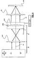
- FIG. 7schematically shows another example of a design for an optical tomography image acquisition system incorporating a quarter wave plate.
- An optical tomography system 100includes an illuminator 15 , a carrier 11 , a variable power element 33 , and a microscope objective assembly 10 .
- a light sensor 30is located in the focal plane of a tube lens 23 that, in turn, is located to receive light beams 13 transmitted from the variable power element 33 .
- image signals acquired by the light sensor 30are transmitted to a computer or like device for storage and image processing including 3D reconstruction.
- the illuminator 15is located to illuminate a portion of carrier 11 .
- the microscope objective assembly 10is located to receive incident light 5 passing through the carrier 11 and objects residing in the carrier 11 .
- the carrier 11may be coupled to a rotational motor as signified by reference arrow 17 . Under control of the rotational motor, the carrier 11 may be rotated to present various views of a transported object to the microscope objective assembly 10 .
- the carrier 11may advantageously comprise an optically transparent capillary tube or equivalent filled with an optical fluid selected for matching the refractive properties of the optics.
- the variable power element 33 and microscope objective assembly 10may be aligned along an optical path 12 . Light 21 transmitted through the objective lens 10 impinges on the variable power element 33 .
- the light sensor 30may advantageously comprise a photosensor array, a CCD array or equivalents.
- the illuminator 15may comprise any suitable illumination source or combination of a plurality of illumination sources including sources producing visible light, near infrared, ultraviolet, and other light frequencies useful for optical tomography of fixed or live biological cells and equivalents.
- a variable power element 33includes a beamsplitter 18 , a scan lens 16 and a scan mirror 14 having a reflecting surface 19 .
- a light sensor 30is located in the focal plane of a tube lens 23 that, in turn, is located to receive light beams 13 reflected from one surface of the beam splitter 18 .
- the scan mirror 14is coupled to be moved in a controlled manner by drive 114 .
- the beam splitter 18 , scan lens 16 and scan mirror 14are aligned along an optical path 12 .
- the beam splitter 18is also tilted at an angle for directing reflected light 13 from the scan mirror 14 through the tube lens 23 , ultimately transmitted onto the light sensor 30 for acquiring images of the tube contents.
- Operating the scan mirror 14comprises oscillating the scan mirror 14 along the optical axis while the reflecting surface 19 of the mirror maintains a substantially perpendicular relationship to the optical axis. As the scan mirror oscillates along the optical axis 12 , a plurality of focal planes in the carrier 11 (shown in FIG. 1 ) are traversed and the resultant pseudo-projection is imaged on the light sensor 30 .
- FIG. 3another example of a design for an optical tomography image acquisition system with a variable power element for high speed scanning is schematically shown.
- An illuminator 15 , a carrier 11 , a variable power element 33 A, and a microscope objective assembly 10are aligned along an optical path 12 , where the optical path 12 may be the optical axis of the microscope objective assembly 10 .
- the microscope objective assembly 10includes an exit pupil E.
- the variable power element 33 Aincludes a first lens 312 and a second lens 314 .
- the second lens 314may advantageously comprise a scanning lens that is driven along the optical axis 12 by drive 114 A.
- the exit pupil E, first lens 312 and second lens 314are each separated by a focal length f. Movement of the second lens 314 operates to translate the second lens by a scanning distance ⁇ to scan focal plans in the carrier 11 .
- the scanning distance ⁇will oscillate between a positive and negative value represented here as f+ ⁇ .
- variable power element 33 Bincludes a variable focal lens 412 .
- the variable focal lens 412may be comprised of a transparent cell filled with two non-miscible fluids made according to “Varioptic” technology.
- Varioptic lensesare based on an electrowetting principle and are controllable using a variable voltage source 114 V.
- Varioptic lensesare commercially available from Varioptic SA, Lyon, France. Such lenses can present large optical power variations.
- a 5 mm diameter Varioptic lenscan have an inverse focal length that varies up to 50 dioptries. (See, e.g., Gabay, et al. “Dynamic Study of a Varioptic variable focal lens,” Current Developments in Lens Design and Optical Engineering III, Proceeding of SPIE Vol. 4767 (2002)).
- FIG. 5another example of a design for an optical tomography image acquisition system with a variable power element and optical relay is schematically shown.
- a microscope objective assembly 10 , an optical relay 510 and a variable power element 33 Care aligned along an optical path.
- the microscope objective assembly 10includes an exit pupil E.
- the variable power element 33 Cmay include a beamsplitter 18 and a scan lens 16 .
- the optical elementsare each separated by a focal length f.
- E′represents the entrance pupil of the scan lens 16 which is coincident with the entrance pupil of the variable power element 33 C.
- the broken line 516indicates the light path for focusing the exit pupil E to be coincident with the entrance pupil E′.
- Light rays 521represent light transmitted through the objective lens 10 .
- Light rays 523represent light relayed by optical relay 510 .
- the beam splitter 18is configured for directing reflected light 13 from the scan lens 16 and scan mirror 14 through the tube lens 23 , ultimately transmitted onto the light sensor 30 for acquiring images of the tube contents.
- the optical relay 510includes a first focal lens 512 aligned with a second lens 514 , where the first and second lenses are spaced by a distance of twice the focal length, 2f.
- a 50 ⁇ objective lens 10 and a 100 ⁇ scan lens 16yields an 8:1 reduction in scan distance required to generate a pseudo-projection, as compared to directly scanning the objective lens 10 .
- the mirrorneed be scanned by only 1.5 microns.
- the scan mirrorneed only be as large as the scanner space field of view, which is typically less than 1 mm. Thus a scan mirror 14 having a 1 mm diameter would be sufficient to reflect the entire image. Such a mirror weighs much less than a typical objective lens, and scanning such a mirror takes much less force and energy than does scanning the objective lens. The lower required force and shorter scan distance allow scan frequencies that are thousands of times greater than are feasible with a scanning objective.
- the scan mirroroscillates at a rate of at least 500 Hz and may also oscillate at a rate of at least 1000 Hz.
- the scan mirror 14 and drive 114may be made from a wide variety of available fabrication technologies.
- One exampleis a conventional first surface mirror attached to a piezoelectric actuator.
- Another exampleis a micro-electro-mechanical-systems (MEMS) flexure with a reflective coating.
- MEMSmicro-electro-mechanical-systems
- Yet another exampleis a metal mirror with a solenoid actuator.
- An acoustic wave generator driving a reflective elastic diaphragmmay also be used.
- One skilled in the artwill recognize that many other combinations of conventional actuators and reflectors may also be used.
- the scan magnification ⁇ z/ ⁇ z′is independent of the numerical aperture (NA) of either the objective lens 10 or scan lens 16 , but the NAs of the two lenses are indirectly tied to the scan magnification.
- NAnumerical aperture
- the entrance pupil E′, of the scan lens 16must be large enough to avoid vignetting in order to realize the resolving power of the objective lens 10 over the entire field of view.
- the scan lens 16 NAbe equal to or larger than the objective lens 10 NA divided by the transverse magnification m T , as follows from the optical invariant.
- the factor m Tties the NAs to the scan magnification ⁇ z/ ⁇ z′. Equality is sufficient when the exit pupil E of the objective lens 10 , or its image, is coincident with the entrance pupil E′ of the scan lens 16 , otherwise the scan lens 16 NA must be larger.
- An optical relaymay be used to image the exit pupil E of objective 10 onto the entrance pupil E′ of scan lens 16 . This is necessary if the lens pupils are virtual pupils, as is the case with most high performance high magnification microscope objectives. Moreover, a relay magnification m E of less than one, may be used to reduce the size of the image of the exit pupil of objective lens 10 to the point where it is the same size as the entrance pupil of scan lens 16 . Using this technique has the side effect of also reducing the scan magnification by m E .
- the image magnificationmust remain constant while scanning to obtain a good pseudoprojection image. This is accomplished by making the system telecentric in scanner space. If the scan lens 16 is a telecentric lens, wherein its entrance pupil lies in its front focal plane, then the system will be telecentric in scanner space if and only if the exit pupil of objective lens 10 , or its image, is coincident with its entrance pupil. If the scan lens 16 is not telecentric, then placing the exit pupil of objective lens 10 , or its image, at the front focal plane of the scan lens 16 will make the system telecentric in scanner space, so long as the objective lens 10 exit pupil is not vignetted by scan lens 16 .
- a relay systemas described in the previous paragraph, may be used to keep the magnification constant while scanning if either of the pupils is a virtual pupil.
- one advantageous embodimentincludes
- FIG. 6an alternate example of a design for an optical tomography image acquisition system with a liquid lens variable power element is schematically shown.
- a microscope objective assembly 10 , a variable power element 33 Bare aligned along an optical path.
- the variable power element 33 Bincludes a variable focal lens 412 , for example a Varioptic lens or equivalent, as discussed above with reference to FIG. 4 .
- An intermediate lens 611is located in the optical path between the microscope objective assembly 10 and the variable power element 33 B.
- the tube lens 23is located to receive light beams 13 transmitted from the variable power element 33 B and transmit the light beams to the light sensor 30 .
- the variable focal lens 412may be located a distance 2f from the intermediate lens 611 .
- the intermediate lens 611may advantageously be located at a distance 2f from the microscope objective assembly 10 .
- An alternate fast scan mirror design 200employs a polarizing beam splitter 218 optical aligned with a quarter wave plate 220 so as to transmit substantially circularly polarized light.
- the reflected light 13 P from the scan mirroris then substantially circularly polarized with opposite handedness.
- the quarter wave plate 220converts this to linear polarization light 13 P′ substantially orthogonal to the incident light 5 .
- the beam splitter 218is configured for directing the linear polarization light 13 P′ from the scan mirror 14 through the tube lens 23 , ultimately transmitted onto the light sensor 30 for acquiring images of the tube contents.
- the other elementsare similar in type, configuration and construction to those as described above with reference to FIG. 1 .
Landscapes
- Physics & Mathematics (AREA)
- General Physics & Mathematics (AREA)
- Optics & Photonics (AREA)
- Chemical & Material Sciences (AREA)
- Analytical Chemistry (AREA)
- Health & Medical Sciences (AREA)
- Life Sciences & Earth Sciences (AREA)
- Biochemistry (AREA)
- General Health & Medical Sciences (AREA)
- Immunology (AREA)
- Pathology (AREA)
- Microscoopes, Condenser (AREA)
- Investigating Or Analysing Materials By Optical Means (AREA)
- Mechanical Light Control Or Optical Switches (AREA)
Abstract
Description
The present invention relates to optical tomographic imaging systems in general, and, more particularly, to a high-speed focal plane scanner for optical projection tomography, in which a small object, such as a biological cell, is imaged by a microscope.
Recently advances in imaging biological cells using optical tomography invented by A. C. Nelson have been disclosed, for example, in U.S. Pat. No. 6,522,775, issued Feb. 18, 2003, and entitled “Apparatus And Method For Imaging Small Objects In A Flow Stream Using Optical Tomography,” the full disclosure of which is incorporated by reference. Further developments in the field are taught in Fauver et al., U.S. Pat. No. 7,738,945 issued on Jun. 15, 2010, entitled “Method And Apparatus Of Shadowgram Formation For Optical Tomography,” and Fauver et al., U.S. Pat. No. 7,907,765, issued on Mar. 15, 2011, entitled “Focal Plane Tracking For Optical Microtomography,” the full disclosures of which are also incorporated by reference.
Processing in such an optical tomography system begins with specimen preparation. Typically, specimens taken from a patient are received from a hospital or clinic and processed to remove non-diagnostic elements, fixed and then stained. Stained specimens are then mixed with an optical fluid, inserted into a micro-capillary tube and images of objects, such as cells, in the specimen are produced using an optical tomography system. The resultant images comprise a set of extended depth of field images from differing perspectives called “pseudo-projection images.” The set of pseudo-projection images can be reconstructed using backprojection and filtering techniques to yield a 3D reconstruction of a cell of interest.
The 3D reconstruction then remains available for analysis in order to enable the quantification and the determination of the location of structures, molecules or molecular probes of interest. An object such as a biological cell may be labeled with a stain or tagged molecular probe, and the measured amount and location of this probe may yield important information about the disease state of the cell, including, but not limited to, various cancers such as lung, breast, prostate, cervical and ovarian cancers.
In one type of optical tomography system, as described in U.S. Pat. No. 7,738,945 and constructed by VisionGate, Inc., the depth of field of the imaging optics is extended by scanning an objective lens transverse to a capillary tube containing a specimen. A piezoelectric transducer (PZT) actuator moves the objective lens sinusoidally several times per second in order to scan a series of focal planes though a specimen. By using a PZT actuator to move the objective lens, a focal plane moving through the specimen has its speed limited by inertia inherent in moving the objective lens rapidly along the optical axis through the specimen. Because the objective lens is housed in a relatively massive assembly, the scan rate is typically, about 10 Hz with a theoretical upper limit of roughly 60 cycles per second. During each scan an image sensor acquires at least one pseudo-projection image. With well-synchronized rotation and objective scanning, an image can be acquired on the down-stroke as well as the up-stroke of the PZT actuator, allowing up to 120 images per second to be acquired. While this is a useful acquisition rate, it can be significantly improved through the apparatus, systems and methods disclosed herein.
An optical projection tomography system and method for imaging an object of interest. An object of interest is illuminated within the field of view of a microscope objective lens located to receive light passing through the object of interest. Light transmitted through the microscope objective lens impinges upon a variable power element. The variable power element is driven to scan through multiple focal planes in the object of interest. Light transmitted from the variable power element is sensed by a sensing element or array.
In the drawings, identical reference numbers identify similar elements or components. The sizes and relative positions of elements in the drawings are not necessarily drawn to scale. For example, the shapes of various elements and angles are not drawn to scale, and some of these elements are arbitrarily enlarged and positioned to improve drawing legibility. Further, the particular shapes of the elements as drawn, are not intended to convey any information regarding the actual shape of the particular elements, and have been solely selected for ease of recognition in the drawings.
The following disclosure describes several embodiments and systems for imaging an object of interest. Several features of methods and systems in accordance with example embodiments of the invention are set forth and described in the Figures. It will be appreciated that methods and systems in accordance with other example embodiments of the invention can include additional procedures or features different than those shown in Figures. Example embodiments are described herein with respect to biological cells. However, it will be understood that these examples are for the purpose of illustrating the principals of the invention, and that the invention is not so limited.
Additionally, methods and systems in accordance with several example embodiments of the invention may not include all of the features shown in these Figures. Throughout the Figures, like reference numbers refer to similar or identical components or procedures.
Unless the context requires otherwise, throughout the specification and claims which follow, the word “comprise” and variations thereof, such as, “comprises” and “comprising” are to be construed in an open, inclusive sense that is as “including, but not limited to.”
Reference throughout this specification to “one example” or “an example embodiment,” “one embodiment,” “an embodiment” or various combinations of these terms means that a particular feature, structure or characteristic described in connection with the embodiment is included in at least one embodiment of the present invention. Thus, the appearances of the phrases “in one embodiment” or “in an embodiment” in various places throughout this specification are not necessarily all referring to the same embodiment. Furthermore, the particular features, structures, or characteristics may be combined in any suitable manner in one or more embodiments.
Definitions
Generally as used herein the following terms have the following meanings when used within the context of optical microscopy processes. The following definitions are provided to promote understanding of the disclosure and are not to be considered limiting:
- “Capillary tube” has its generally accepted meaning and is intended to include transparent microcapillary tubes and equivalent items with an inside diameter generally of 500 microns or less.
- “Depth of field” is the length along the optical axis within which the focal plane may be shifted before an unacceptable image blur for a specified feature is produced.
- “Object” means an individual cell, particle, item, thing or other entity.
- “Pseudoprojection” includes a single image representing a sampled volume of extent larger than the native depth of field of the optics. One concept of a pseudoprojection is taught in U.S. Pat. No. 7,738,945.
- “Specimen” means a complete product obtained from a single test or procedure from an individual patient (e.g., sputum submitted for analysis, a biopsy, or a nasal swab). A specimen may be composed of one or more objects. The result of the specimen diagnosis becomes part of the case diagnosis.
- “Sample” means a finished cellular preparation that is ready for analysis, including all or part of an aliquot or specimen.
Referring now toFIG. 1 , an example of a design for an optical tomography image acquisition system with a variable power element for high speed scanning is schematically shown. Anoptical tomography system 100 includes anilluminator 15, acarrier 11, avariable power element 33, and a microscopeobjective assembly 10. Alight sensor 30 is located in the focal plane of atube lens 23 that, in turn, is located to receivelight beams 13 transmitted from thevariable power element 33. In an optical tomography system, for example, image signals acquired by thelight sensor 30 are transmitted to a computer or like device for storage and image processing including 3D reconstruction.
In one embodiment, theilluminator 15 is located to illuminate a portion ofcarrier 11. The microscopeobjective assembly 10 is located to receiveincident light 5 passing through thecarrier 11 and objects residing in thecarrier 11. Thecarrier 11 may be coupled to a rotational motor as signified byreference arrow 17. Under control of the rotational motor, thecarrier 11 may be rotated to present various views of a transported object to the microscopeobjective assembly 10. Thecarrier 11 may advantageously comprise an optically transparent capillary tube or equivalent filled with an optical fluid selected for matching the refractive properties of the optics. Thevariable power element 33 and microscopeobjective assembly 10 may be aligned along anoptical path 12.Light 21 transmitted through theobjective lens 10 impinges on thevariable power element 33.
Thelight sensor 30 may advantageously comprise a photosensor array, a CCD array or equivalents. Theilluminator 15 may comprise any suitable illumination source or combination of a plurality of illumination sources including sources producing visible light, near infrared, ultraviolet, and other light frequencies useful for optical tomography of fixed or live biological cells and equivalents.
Referring now toFIG. 2 , a more detailed example of a design for a variable power element and imaging optics is schematically shown. Avariable power element 33 includes abeamsplitter 18, ascan lens 16 and ascan mirror 14 having a reflectingsurface 19. Alight sensor 30 is located in the focal plane of atube lens 23 that, in turn, is located to receivelight beams 13 reflected from one surface of thebeam splitter 18. Thescan mirror 14 is coupled to be moved in a controlled manner bydrive 114.
Thebeam splitter 18,scan lens 16 andscan mirror 14 are aligned along anoptical path 12. Thebeam splitter 18 is also tilted at an angle for directing reflected light13 from thescan mirror 14 through thetube lens 23, ultimately transmitted onto thelight sensor 30 for acquiring images of the tube contents. Operating thescan mirror 14 comprises oscillating thescan mirror 14 along the optical axis while the reflectingsurface 19 of the mirror maintains a substantially perpendicular relationship to the optical axis. As the scan mirror oscillates along theoptical axis 12, a plurality of focal planes in the carrier11 (shown inFIG. 1 ) are traversed and the resultant pseudo-projection is imaged on thelight sensor 30.
Referring now toFIG. 3 , another example of a design for an optical tomography image acquisition system with a variable power element for high speed scanning is schematically shown. Anilluminator 15, acarrier 11, avariable power element 33A, and a microscopeobjective assembly 10 are aligned along anoptical path 12, where theoptical path 12 may be the optical axis of the microscopeobjective assembly 10. The microscopeobjective assembly 10 includes an exit pupil E. Thevariable power element 33A includes afirst lens 312 and asecond lens 314. Thesecond lens 314 may advantageously comprise a scanning lens that is driven along theoptical axis 12 bydrive 114A. The exit pupil E,first lens 312 andsecond lens 314 are each separated by a focal length f. Movement of thesecond lens 314 operates to translate the second lens by a scanning distance Δ to scan focal plans in thecarrier 11. In this example, the scanning distance Δ will oscillate between a positive and negative value represented here as f+Δ.
Referring now toFIG. 4 , another example of a design for a variable power element is schematically shown. Thevariable power element 33B includes a variablefocal lens 412. In one embodiment, the variablefocal lens 412 may be comprised of a transparent cell filled with two non-miscible fluids made according to “Varioptic” technology. Such Varioptic lenses are based on an electrowetting principle and are controllable using avariable voltage source 114V. Varioptic lenses are commercially available from Varioptic SA, Lyon, France. Such lenses can present large optical power variations. For example, a 5 mm diameter Varioptic lens can have an inverse focal length that varies up to 50 dioptries. (See, e.g., Gabay, et al. “Dynamic Study of a Varioptic variable focal lens,” Current Developments in Lens Design and Optical Engineering III, Proceeding of SPIE Vol. 4767 (2002)).
Referring now toFIG. 5 , another example of a design for an optical tomography image acquisition system with a variable power element and optical relay is schematically shown. A microscopeobjective assembly 10, anoptical relay 510 and avariable power element 33C are aligned along an optical path. The microscopeobjective assembly 10 includes an exit pupil E. In one example, thevariable power element 33C may include abeamsplitter 18 and ascan lens 16. The optical elements are each separated by a focal length f. E′ represents the entrance pupil of thescan lens 16 which is coincident with the entrance pupil of thevariable power element 33C. Thebroken line 516 indicates the light path for focusing the exit pupil E to be coincident with the entrance pupil E′.Light rays 521 represent light transmitted through theobjective lens 10.Light rays 523 represent light relayed byoptical relay 510.
Thebeam splitter 18 is configured for directing reflected light13 from thescan lens 16 andscan mirror 14 through thetube lens 23, ultimately transmitted onto thelight sensor 30 for acquiring images of the tube contents. Theoptical relay 510 includes a firstfocal lens 512 aligned with asecond lens 514, where the first and second lenses are spaced by a distance of twice the focal length, 2f.
Having described the structure of example embodiments, a description of the operation of example embodiments should prove helpful to further understanding of the principles of the disclosure. Translating the scan mirror14 a distance Δz′ produces a focus shift Δz at the object equal to 2 Δz′ n/(n′ mT2), where n is the object space index of refraction, n′ is the scanner space index of refraction, mTis the transverse magnification between the object and scanner. The factor of 2 is due to the fact that the optical path length changes by twice the mirror translation. Thus, by choosing an advantageous magnification ratio between the imaging objective and the scanning objective, focus can be translated using the scanning mirror with significantly less motion than would be required by moving the objective relative to the object. For example, a 50×objective lens 10 and a 100× scan lens16 (i.e. transverse magnification mT=0.5) yields an 8:1 reduction in scan distance required to generate a pseudo-projection, as compared to directly scanning theobjective lens 10. Continuing this example, to create a 12 micron pseudo projection, the mirror need be scanned by only 1.5 microns.
The scan mirror need only be as large as the scanner space field of view, which is typically less than 1 mm. Thus ascan mirror 14 having a 1 mm diameter would be sufficient to reflect the entire image. Such a mirror weighs much less than a typical objective lens, and scanning such a mirror takes much less force and energy than does scanning the objective lens. The lower required force and shorter scan distance allow scan frequencies that are thousands of times greater than are feasible with a scanning objective. The scan mirror oscillates at a rate of at least 500 Hz and may also oscillate at a rate of at least 1000 Hz.
Thescan mirror 14 and drive114 may be made from a wide variety of available fabrication technologies. One example is a conventional first surface mirror attached to a piezoelectric actuator. Another example is a micro-electro-mechanical-systems (MEMS) flexure with a reflective coating. Yet another example is a metal mirror with a solenoid actuator. An acoustic wave generator driving a reflective elastic diaphragm may also be used. One skilled in the art will recognize that many other combinations of conventional actuators and reflectors may also be used.
The scan magnification Δz/Δz′ is independent of the numerical aperture (NA) of either theobjective lens 10 orscan lens 16, but the NAs of the two lenses are indirectly tied to the scan magnification. Specifically, the entrance pupil E′, of thescan lens 16 must be large enough to avoid vignetting in order to realize the resolving power of theobjective lens 10 over the entire field of view. A consequence of this condition is that thescan lens 16 NA be equal to or larger than theobjective lens 10 NA divided by the transverse magnification mT, as follows from the optical invariant. The factor mTties the NAs to the scan magnification Δz/Δz′. Equality is sufficient when the exit pupil E of theobjective lens 10, or its image, is coincident with the entrance pupil E′ of thescan lens 16, otherwise thescan lens 16 NA must be larger.
An optical relay may be used to image the exit pupil E of objective10 onto the entrance pupil E′ ofscan lens 16. This is necessary if the lens pupils are virtual pupils, as is the case with most high performance high magnification microscope objectives. Moreover, a relay magnification mEof less than one, may be used to reduce the size of the image of the exit pupil ofobjective lens 10 to the point where it is the same size as the entrance pupil ofscan lens 16. Using this technique has the side effect of also reducing the scan magnification by mE.
The image magnification must remain constant while scanning to obtain a good pseudoprojection image. This is accomplished by making the system telecentric in scanner space. If thescan lens 16 is a telecentric lens, wherein its entrance pupil lies in its front focal plane, then the system will be telecentric in scanner space if and only if the exit pupil ofobjective lens 10, or its image, is coincident with its entrance pupil. If thescan lens 16 is not telecentric, then placing the exit pupil ofobjective lens 10, or its image, at the front focal plane of thescan lens 16 will make the system telecentric in scanner space, so long as theobjective lens 10 exit pupil is not vignetted byscan lens 16. Once again, a relay system, as described in the previous paragraph, may be used to keep the magnification constant while scanning if either of the pupils is a virtual pupil.
If larger objects are scanned with lowerobjective lens 10 magnification, there is no need to change the scanning lens or translation distance Δz′. For example if a 20× lens is used for another application, the objective magnification ratio is 5:1 (i.e. transverse magnification mT=0.2) yielding a 50:1 scan ratio. Thus a 1 micron translation of the position of the scan mirror produces a 50 micron shift in focal position of the image under the 20× lens. This allows scanning large ranges with micron or submicron motion. This is ideal for piezoelectric devices which are very precise. Such precision piezoelectric devices having motion characteristics of about 4 nm/volt motion, but with travel limited to about 10 microns, are commercially available.
Given the principles described, and assuming high performance microscope objectives with virtual pupils are used forobjective lens 10 andscan lens 16, one advantageous embodiment includes
- (1) A scan lens having as high an NA as possible,
- (2) A relay system to image the objective lens exit pupil onto the scan lens entrance pupil, and
- (3) An objective lens whose NA matches the scan lens NA divided by the transverse magnification mT.
Referring now toFIG. 6 , an alternate example of a design for an optical tomography image acquisition system with a liquid lens variable power element is schematically shown. A microscopeobjective assembly 10, avariable power element 33B are aligned along an optical path. Thevariable power element 33B includes a variablefocal lens 412, for example a Varioptic lens or equivalent, as discussed above with reference toFIG. 4 . Anintermediate lens 611 is located in the optical path between the microscopeobjective assembly 10 and thevariable power element 33B. Thetube lens 23 is located to receivelight beams 13 transmitted from thevariable power element 33B and transmit the light beams to thelight sensor 30. In one example, the variablefocal lens 412 may be located adistance 2f from theintermediate lens 611. Theintermediate lens 611 may advantageously be located at adistance 2f from the microscopeobjective assembly 10.
Referring now toFIG. 7 , an example of an alternate design for an optical tomography system with a fast mechanical scan mirror employing a scan mirror used in cooperation with a quarter wave plate is schematically shown. An alternate fastscan mirror design 200 employs apolarizing beam splitter 218 optical aligned with aquarter wave plate 220 so as to transmit substantially circularly polarized light. The reflected light13P from the scan mirror is then substantially circularly polarized with opposite handedness. Thequarter wave plate 220 converts this to linear polarization light13P′ substantially orthogonal to theincident light 5. Thebeam splitter 218 is configured for directing the linear polarization light13P′ from thescan mirror 14 through thetube lens 23, ultimately transmitted onto thelight sensor 30 for acquiring images of the tube contents. The other elements are similar in type, configuration and construction to those as described above with reference toFIG. 1 .
The invention has been described herein in considerable detail in order to comply with the Patent Statutes and to provide those skilled in the art with the information needed to apply the novel principles of the present invention, and to construct and use such exemplary and specialized components as are required. However, it is to be understood that the invention may be carried out by specifically different equipment, and devices, and that various modifications, both as to the equipment details and operating procedures, may be accomplished without departing from the true spirit and scope of the present invention.
Claims (30)
1. An optical projection tomography system for imaging an object of interest, the optical projection tomography system comprising:
an illumination source;
a carrier for holding the object of interest, a portion of which is located within the region illuminated by the light source, wherein the object of interest has at least one feature of interest located within the carrier;
a microscope objective lens located to receive light passing through the carrier, the microscope objective lens located on an optical path;
a variable power element located along the optical path, wherein the variable power element includes:
a beam splitter,
a scan lens,
a scan mirror having a reflective surface for receiving light transmitted through the scan lens, where the microscope objective lens, the beam splitter, the scan lens, and the scan mirror are aligned along the optical path, and
a driver coupled to oscillate the scan mirror along the optical path such that the reflecting surface remains perpendicular to the optical path whereby the oscillating scan mirror scans through a plurality of focal planes in the carrier;
a second lens for receiving and transmitting light emitted from the variable power element; and
a light sensor located to receive light transmitted from the second lens element.
2. The system ofclaim 1 wherein the second lens includes a tube lens; and wherein the beam splitter is also arranged to direct reflected light from the scan mirror through the tube lens.
3. The system ofclaim 1 , wherein the driver comprises a piezoelectric transducer.
4. The system ofclaim 1 wherein the scan mirror oscillates at a rate of at least 500 Hz.
5. The system ofclaim 1 wherein the scan mirror oscillates at a rate of at least 1000 Hz.
6. The system ofclaim 1 wherein oscillation of the scan mirror results in a proportionally longer depth extension of a pseudo-projection image sensed by the light sensor.
7. The system ofclaim 1 wherein the driver comprises a piezoelectric actuator.
8. The system ofclaim 1 wherein the scan mirror and driver comprise a micro-electro-mechanical-systems flexure with a reflective coating.
9. The system ofclaim 1 wherein the scan mirror and driver comprise a metal mirror with a solenoid actuator.
10. The system ofclaim 1 wherein the driver comprises an acoustic wave generator driving a reflective elastic diaphragm.
11. The system ofclaim 1 wherein the carrier comprises an optically transparent capillary tube.
12. The system ofclaim 1 wherein the carrier is coupled to a rotational motor.
13. The system ofclaim 1 wherein the object is moved relatively to the light sensor to present multiple views for producing at least one image of the at least one feature of interest at each view.
14. The system ofclaim 1 wherein the object of interest comprises a biological cell.
15. The system ofclaim 1 wherein the light sensor comprises a detector selected from the group consisting of charge coupled devices, complementary metal-oxide-semiconductor devices, solid-state image sensors, and solid-state image sensor detector arrays.
16. The system ofclaim 1 , wherein the carrier comprises an optically transparent capillary tube with a diameter of at least 50 microns.
17. The system ofclaim 1 wherein the scan lens has a numerical aperture (NA) value and an entrance pupil, and the microscope objective lens has an exit pupil, the system further comprising:
an optical relay positioned to image the microscope objective lens exit pupil onto the scan lens entrance pupil; and
where the microscope objective lens has an NA value that matches the scan lens NA value divided by the transverse magnification value (mT) between the object and the scan mirror.
18. The system ofclaim 1 wherein the microscope objective lens includes an exit pupil E and the variable power element (VPE) has a VPE entrance pupil E′ comprises a beamsplitter, a scan mirror and a scan lens having an entrance pupil which is coincident with the VPE entrance pupil, where the exit pupil E is focused to be coincident with the entrance pupil E′ and the beamsplitter, the scan mirror and the scan lens are aligned along an optical path with the microscope objective lens, and wherein the scan mirror is controlled by a driver.
19. The system ofclaim 18 further comprising an optical relay between the microscope objective lens and the variable power element.
20. The system ofclaim 19 wherein translating the scan mirror a distance Δz′ produces a focus shift Δz at the object equal to 2 Δz′ n/(n′ mT2), where n is the object space index of refraction, n′ is the scanner space index of refraction, and mTis the transverse magnification between an object and the scan mirror.
21. The system ofclaim 1 wherein the scan lens has an NA at least equal to the microscope objective lens NA divided by the transverse magnification mTbetween the object and scan mirror.
22. The system ofclaim 21 wherein the scan lens comprises a telecentric lens.
23. An optical projection tomography method for imaging an object of interest, the optical projection tomography method comprising:
illuminating at least part of the object of interest within the field of view of a microscope objective lens located to receive light passing through the object of interest;
transmitting light through the microscope objective lens to impinge upon a variable power element;
driving the variable power element with respect to the microscope objective lens to scan through multiple focal planes in the object of interest, wherein driving the variable power element includes oscillating a scan mirror with a reflecting surface along an optical path such that the reflecting surface remains perpendicular to the optical path, whereby the oscillating scan mirror scans through a plurality of focal planes in the carrier; and
sensing light transmitted from the variable power element.
24. The method ofclaim 23 wherein the scan mirror oscillates at a rate of at least 500 Hz.
25. The method ofclaim 23 wherein the scan mirror oscillates at a rate of at least 1000 Hz.
26. The method ofclaim 23 wherein driving the variable power element comprises translating a scan mirror a distance Δz′ to produces a focus shift Δz at the object equal to a value according to the mathematical formula
2 Δz′n/(n′mT2),
2 Δz′n/(n′mT2),
where n is the object space index of refraction, n′ is the scanner space index of refraction, mTis the transverse magnification between the object of interest and the scan mirror.
27. The method ofclaim 23 further comprising holding the object of interest in a carrier, and rotating the carrier.
28. The method ofclaim 23 further comprising moving the object of interest relatively to the light sensor to present multiple views.
29. The method ofclaim 23 wherein the object of interest comprises a biological cell.
30. The method ofclaim 23 wherein transmitting light comprises imaging a microscope objective lens exit pupil onto a scan lens entrance pupil.
Priority Applications (7)
| Application Number | Priority Date | Filing Date | Title |
|---|---|---|---|
| US12/391,096US8254023B2 (en) | 2009-02-23 | 2009-02-23 | Optical tomography system with high-speed scanner |
| AU2010215794AAU2010215794B2 (en) | 2009-02-23 | 2010-02-22 | Optical tomography system with high-speed scanner |
| CN201080017727.0ACN102428343B (en) | 2009-02-23 | 2010-02-22 | Optical tomography system with high-speed scanner |
| EP10744448.1AEP2406580A4 (en) | 2009-02-23 | 2010-02-22 | Optical tomography system with high-speed scanner |
| JP2011551280AJP2012518794A (en) | 2009-02-23 | 2010-02-22 | Optical tomography system with high-speed scanner |
| PCT/US2010/024959WO2010096786A2 (en) | 2009-02-23 | 2010-02-22 | Optical tomography system with high-speed scanner |
| CA2752878ACA2752878C (en) | 2009-02-23 | 2010-02-22 | Optical tomography system with high-speed scanner |
Applications Claiming Priority (1)
| Application Number | Priority Date | Filing Date | Title |
|---|---|---|---|
| US12/391,096US8254023B2 (en) | 2009-02-23 | 2009-02-23 | Optical tomography system with high-speed scanner |
Publications (2)
| Publication Number | Publication Date |
|---|---|
| US20100214639A1 US20100214639A1 (en) | 2010-08-26 |
| US8254023B2true US8254023B2 (en) | 2012-08-28 |
Family
ID=42630747
Family Applications (1)
| Application Number | Title | Priority Date | Filing Date |
|---|---|---|---|
| US12/391,096Expired - Fee RelatedUS8254023B2 (en) | 2009-02-23 | 2009-02-23 | Optical tomography system with high-speed scanner |
Country Status (7)
| Country | Link |
|---|---|
| US (1) | US8254023B2 (en) |
| EP (1) | EP2406580A4 (en) |
| JP (1) | JP2012518794A (en) |
| CN (1) | CN102428343B (en) |
| AU (1) | AU2010215794B2 (en) |
| CA (1) | CA2752878C (en) |
| WO (1) | WO2010096786A2 (en) |
Cited By (17)
| Publication number | Priority date | Publication date | Assignee | Title |
|---|---|---|---|---|
| US20120105600A1 (en)* | 2008-06-20 | 2012-05-03 | Meyer Michael G | Functional imaging of cells with optical projection tomography |
| US20120176475A1 (en)* | 2011-01-07 | 2012-07-12 | Zeta Instruments, Inc. | 3D Microscope Including Insertable Components To Provide Multiple Imaging And Measurement Capabilities |
| US20130293882A1 (en)* | 2011-06-21 | 2013-11-07 | Alakai Defense Systems, Inc. | Laser detection system and method |
| US20160062100A1 (en)* | 2014-08-26 | 2016-03-03 | The Board Of Trustees Of The Leland Stanford Junior University | Light-field microscopy with phase masking |
| US20160089025A1 (en)* | 2013-05-10 | 2016-03-31 | James Fujimoto | Oct vitrectomy probe |
| US9495516B2 (en) | 2012-11-21 | 2016-11-15 | The Trustees Of Columbia University In The City Of New York | Systems, methods, and devices for image reconstruction using combined PDE-constrained and simplified spherical harmonics algorithm |
| US9594072B2 (en) | 2015-06-30 | 2017-03-14 | Visiongate, Inc. | System and method for determining cell adequacy in a cytological analysis system |
| WO2017117210A1 (en) | 2015-12-30 | 2017-07-06 | Visiongate, Inc. | System and method for automated detection and monitoring of dysplasia and administration of chemoprevention |
| US20170322381A1 (en)* | 2014-10-31 | 2017-11-09 | Sumitomo Electric Industries, Ltd. | Light emitting module and multi-channel light emitting module |
| US20190025193A1 (en)* | 2017-07-24 | 2019-01-24 | Visiongate, Inc. | Apparatus and method for measuring microscopic object velocities in flow |
| US10884227B2 (en) | 2016-11-10 | 2021-01-05 | The Trustees Of Columbia University In The City Of New York | Rapid high-resolution imaging methods for large samples |
| US11069054B2 (en) | 2015-12-30 | 2021-07-20 | Visiongate, Inc. | System and method for automated detection and monitoring of dysplasia and administration of immunotherapy and chemotherapy |
| US11067783B2 (en)* | 2016-02-23 | 2021-07-20 | Leica Microsystems Cms Gmbh | Light sheet microscope and method for imaging a sample by light sheet microscopy |
| US20220197002A1 (en)* | 2020-09-14 | 2022-06-23 | Singular Genomics Systems, Inc. | Methods and systems for multidimensional imaging |
| US11428692B2 (en) | 2018-07-11 | 2022-08-30 | Visiongate, Inc. | Specimen enrichment for optical tomography cell analysis |
| US11545237B2 (en) | 2017-09-26 | 2023-01-03 | Visiongate, Inc. | Morphometric genotyping of cells in liquid biopsy using optical tomography |
| US11551043B2 (en) | 2018-02-28 | 2023-01-10 | Visiongate, Inc. | Morphometric detection of malignancy associated change |
Families Citing this family (13)
| Publication number | Priority date | Publication date | Assignee | Title |
|---|---|---|---|---|
| US10180564B2 (en)* | 2013-07-02 | 2019-01-15 | Nanyang Technological University | Methods and systems for transport-of-intensity imaging |
| JP6459296B2 (en)* | 2014-08-20 | 2019-01-30 | 住友電気工業株式会社 | Light emitting module and multi-channel light emitting module |
| JP6340902B2 (en)* | 2014-05-13 | 2018-06-13 | 住友電気工業株式会社 | Manufacturing method of optical module |
| US9780882B2 (en)* | 2014-05-13 | 2017-10-03 | Sumitomo Electric Industries, Ltd. | Optical transmitter module having multiple signal lanes |
| CN104251671A (en)* | 2014-09-19 | 2014-12-31 | 七海测量技术(深圳)有限公司 | Real-timely corrected high-precision measurement method and device |
| EP3053506A1 (en)* | 2015-02-06 | 2016-08-10 | Qioptiq Photonics GmbH & Co. KG | Intravaginal camera |
| CN106405753B (en)* | 2015-08-03 | 2020-05-08 | 住友电气工业株式会社 | Method for manufacturing optical assembly and optical assembly |
| JP6634263B2 (en) | 2015-10-16 | 2020-01-22 | オリンパス株式会社 | microscope |
| US10456043B2 (en)* | 2017-01-12 | 2019-10-29 | Align Technology, Inc. | Compact confocal dental scanning apparatus |
| CN111399333B (en)* | 2020-05-13 | 2025-06-24 | 荆门市探梦科技有限公司 | A Bragg period scanning holographic imager |
| CN111913294A (en)* | 2020-09-07 | 2020-11-10 | 中国工程物理研究院机械制造工艺研究所 | Non-mechanical scanning structured light microscopic three-dimensional imaging device and imaging method |
| WO2024190281A1 (en)* | 2023-03-16 | 2024-09-19 | ソニーグループ株式会社 | Analysis system and analysis method |
| ES2993994B2 (en)* | 2023-07-07 | 2025-05-26 | Univ Valencia | Accessory for obtaining a stack of focal images, microscope comprising it and method of obtaining a focal image |
Citations (118)
| Publication number | Priority date | Publication date | Assignee | Title |
|---|---|---|---|---|
| US3560754A (en) | 1965-11-17 | 1971-02-02 | Ibm | Photoelectric particle separator using time delay |
| US3598471A (en) | 1968-11-22 | 1971-08-10 | Corning Glass Works | Optical contrast enhancement system |
| US3657537A (en) | 1970-04-03 | 1972-04-18 | Bausch & Lomb | Computerized slit-scan cyto-fluorometer for automated cell recognition |
| US3705771A (en) | 1970-01-14 | 1972-12-12 | Bio Physics Systems Inc | Photoanalysis apparatus |
| US3960449A (en) | 1975-06-05 | 1976-06-01 | The Board Of Trustees Of Leland Stanford Junior University | Measurement of angular dependence of scattered light in a flowing stream |
| US3999047A (en) | 1972-09-05 | 1976-12-21 | Green James E | Method and apparatus utilizing color algebra for analyzing scene regions |
| US4081277A (en) | 1976-10-08 | 1978-03-28 | Eastman Kodak Company | Method for making a solid-state color imaging device having an integral color filter and the device |
| US4110043A (en) | 1975-09-27 | 1978-08-29 | Gesellschaft Fur Strahlen- Und Umweltforschung Mbh, Munchen | Apparatus for counting and classifying particles |
| US4175860A (en) | 1977-05-31 | 1979-11-27 | Rush-Presbyterian-St. Luke's Medical Center | Dual resolution method and apparatus for use in automated classification of pap smear and other samples |
| US4183623A (en) | 1977-10-11 | 1980-01-15 | Haines Kenneth A | Tomographic cross-sectional imaging using incoherent optical processing |
| US4293221A (en) | 1979-04-17 | 1981-10-06 | Research Corporation | Multidimensional slit-scan flow system |
| US4360885A (en) | 1980-01-02 | 1982-11-23 | Edgar Albert D | Micro-optical tomography |
| US4702598A (en) | 1985-02-25 | 1987-10-27 | Research Corporation | Flow cytometer |
| US4786165A (en) | 1986-07-10 | 1988-11-22 | Toa Medical Electronics Co., Ltd. | Flow cytometry and apparatus therefor |
| US4858128A (en) | 1986-08-11 | 1989-08-15 | General Electric Company | View-to-view image correction for object motion |
| US4873653A (en) | 1986-04-09 | 1989-10-10 | Carl-Zeiss-Stiftung | Microscope system for providing three-dimensional resolution |
| US5034613A (en) | 1989-11-14 | 1991-07-23 | Cornell Research Foundation, Inc. | Two-photon laser microscopy |
| US5117466A (en) | 1991-04-30 | 1992-05-26 | The United States Of America As Represented By The United States Department Of Energy | Integrated fluorescence analysis system |
| US5125737A (en) | 1987-03-13 | 1992-06-30 | Coulter Electronics, Inc. | Multi-part differential analyzing apparatus utilizing light scatter techniques |
| US5141609A (en) | 1990-11-16 | 1992-08-25 | The Trustees Of The Leland Stanford Junior University | Method and device employing time-delayed integration for detecting sample components after separation |
| US5148502A (en) | 1988-02-23 | 1992-09-15 | Olympus Optical Co., Ltd. | Optical image input/output apparatus for objects having a large focal depth |
| US5159398A (en) | 1991-02-27 | 1992-10-27 | Toa Medical Electronics Co., Ltd. | Flow imaging cytometer |
| US5189518A (en) | 1989-10-17 | 1993-02-23 | Mitsubishi Denki Kabushiki Kaisha | Image blur correcting apparatus |
| US5281517A (en) | 1985-11-04 | 1994-01-25 | Cell Analysis Systems, Inc. | Methods for immunoploidy analysis |
| US5308990A (en) | 1991-05-15 | 1994-05-03 | Hitachi, Ltd. | Method for measuring microparticles, quantitative measuring method therefor and instrument for measuring microparticles |
| US5312535A (en) | 1992-07-17 | 1994-05-17 | Beckman Instruments, Inc. | Capillary electrophoresis detection |
| US5321501A (en) | 1991-04-29 | 1994-06-14 | Massachusetts Institute Of Technology | Method and apparatus for optical imaging with means for controlling the longitudinal range of the sample |
| US5333164A (en) | 1991-12-11 | 1994-07-26 | General Electric Company | Method and apparatus for acquiring and processing only a necessary volume of radon data consistent with the overall shape of the object for efficient three dimensional image reconstruction |
| US5390226A (en) | 1992-07-02 | 1995-02-14 | General Electric Company | Method and apparatus for pre-processing cone beam projection data for exact three dimensional computer tomographic image reconstruction of a portion of an object |
| US5402460A (en) | 1993-08-02 | 1995-03-28 | University Of Washington | Three-dimensional microtomographic analysis system |
| US5428447A (en)* | 1992-07-31 | 1995-06-27 | Fuji Photo Film Co., Ltd. | Method and apparatus for obtaining three-dimensional information of samples using computer tomography |
| US5539800A (en) | 1995-03-24 | 1996-07-23 | The Regents Of The University Of California, Office Of Technology Transfer | Pseudolocal tomography |
| US5548395A (en) | 1991-09-20 | 1996-08-20 | Toa Medical Electronics Co., Ltd. | Particle analyzer |
| US5552605A (en) | 1994-11-18 | 1996-09-03 | Picker International, Inc. | Motion correction based on reprojection data |
| US5644388A (en) | 1994-04-19 | 1997-07-01 | Toa Medical Electronics Co., Ltd. | Imaging flow cytometer nearly simultaneously capturing a plurality of images |
| US5680484A (en) | 1992-06-09 | 1997-10-21 | Olympus Optical Co., Ltd. | Optical image reconstructing apparatus capable of reconstructing optical three-dimensional image having excellent resolution and S/N ratio |
| US5710429A (en) | 1995-04-06 | 1998-01-20 | Alfano; Robert R. | Ultrafast optical imaging of objects in or behind scattering media |
| US5741411A (en) | 1995-05-19 | 1998-04-21 | Iowa State University Research Foundation | Multiplexed capillary electrophoresis system |
| US5760901A (en) | 1997-01-28 | 1998-06-02 | Zetetic Institute | Method and apparatus for confocal interference microscopy with background amplitude reduction and compensation |
| US5760951A (en) | 1992-09-01 | 1998-06-02 | Arthur Edward Dixon | Apparatus and method for scanning laser imaging of macroscopic samples |
| US5786893A (en)* | 1993-04-15 | 1998-07-28 | Board Of Regents, The University Of Texas System | Raman spectrometer |
| US5831723A (en) | 1996-04-03 | 1998-11-03 | Toa Medical Electronics Co., Ltd. | Particle analyzer |
| US5835617A (en) | 1996-01-18 | 1998-11-10 | Hamamatsu Photonics K.K. | Optical computer tomographic apparatus and image reconstruction method using optical computer tomography |
| US5880838A (en) | 1996-06-05 | 1999-03-09 | California Institute Of California | System and method for optically measuring a structure |
| US5915048A (en) | 1996-06-05 | 1999-06-22 | Zetetic Institute | Method and apparatus for discriminating in-focus images from out-of-focus light signals from background and foreground light sources |
| US6005617A (en) | 1996-03-11 | 1999-12-21 | Matsushita Electric Industrial Co., Ltd. | Electronic camera with mechanical subscanner |
| US6026174A (en) | 1992-10-14 | 2000-02-15 | Accumed International, Inc. | System and method for automatically detecting malignant cells and cells having malignancy-associated changes |
| US6038067A (en) | 1996-05-23 | 2000-03-14 | The Regents Of The University Of California | Scanning computed confocal imager |
| US6078681A (en) | 1996-03-18 | 2000-06-20 | Marine Biological Laboratory | Analytical imaging system and process |
| US6091983A (en) | 1997-02-07 | 2000-07-18 | Alfano; Robert R. | Imaging of objects in turbid media based upon the preservation of polarized luminescence emitted from contrast agents |
| US6130958A (en) | 1996-11-29 | 2000-10-10 | Imaging Diagnostic Systems, Inc. | Method for reconstructing the image of an object scanned with a laser imaging apparatus |
| US6177277B1 (en) | 1995-01-16 | 2001-01-23 | Erkki Soini | Flow fluorometric method |
| US6201628B1 (en) | 1997-11-19 | 2001-03-13 | University Of Washington | High throughput optical scanner |
| US6211955B1 (en) | 2000-01-24 | 2001-04-03 | Amnis Corporation | Imaging and analyzing parameters of small moving objects such as cells |
| US6215587B1 (en) | 1994-02-14 | 2001-04-10 | Robert R. Alfano | Microscope imaging inside highly scattering media |
| US6239871B1 (en) | 1999-08-24 | 2001-05-29 | Waters Investments Limited | Laser induced fluorescence capillary interface |
| US6248988B1 (en) | 1998-05-05 | 2001-06-19 | Kla-Tencor Corporation | Conventional and confocal multi-spot scanning optical microscope |
| US6251615B1 (en) | 1998-02-20 | 2001-06-26 | Cell Analytics, Inc. | Cell analysis methods |
| US6251586B1 (en) | 1995-10-02 | 2001-06-26 | The United States Of America As Represented By The Department Of Health And Human Services | Epithelial protein and DNA thereof for use in early cancer detection |
| US6256096B1 (en) | 1999-01-11 | 2001-07-03 | Softray | Flow cytometry apparatus and method |
| US20010012069A1 (en) | 1997-04-07 | 2001-08-09 | Eberhard Derndinger | Confocal microscope with a motorized scanning table |
| US6291824B1 (en) | 1998-04-13 | 2001-09-18 | Board Of Supervisors Of Louisiana State University And Agricultural And Mechanical College | Apparatus and method for high-bandwidth optical tomography |
| US6312914B1 (en) | 1992-09-14 | 2001-11-06 | Orasure Technologies, Inc. | Up-converting reporters for biological and other assays |
| US6365367B1 (en) | 1999-12-06 | 2002-04-02 | Cellomics, Inc. | Environmental chamber for the analysis of live cells |
| US6374128B1 (en)* | 1998-11-20 | 2002-04-16 | Fuji Photo Film Co., Ltd. | Blood vessel imaging system |
| US6388809B1 (en) | 1997-10-29 | 2002-05-14 | Digital Optical Imaging Corporation | Methods and apparatus for improved depth resolution use of out-of-focus information in microscopy |
| US20020122167A1 (en) | 2000-08-25 | 2002-09-05 | Riley James K. | Measuring the velocity of small moving objects such as cells |
| US6473176B2 (en) | 1999-01-25 | 2002-10-29 | Amnis Corporation | Imaging and analyzing parameters of small moving objects such as cells |
| US6519355B2 (en) | 2001-03-28 | 2003-02-11 | Alan C. Nelson | Optical projection imaging system and method for automatically detecting cells having nuclear and cytoplasmic densitometric features associated with disease |
| US6522775B2 (en) | 2001-03-28 | 2003-02-18 | Alan C. Nelson | Apparatus and method for imaging small objects in a flow stream using optical tomography |
| US6529614B1 (en) | 1998-08-05 | 2003-03-04 | California Institute Of Technology | Advanced miniature processing handware for ATR applications |
| US6540895B1 (en) | 1997-09-23 | 2003-04-01 | California Institute Of Technology | Microfabricated cell sorter for chemical and biological materials |
| US20030063384A1 (en) | 2001-08-31 | 2003-04-03 | Dowski Edward Raymond | Wavefront coding optics |
| US6591003B2 (en) | 2001-03-28 | 2003-07-08 | Visiongate, Inc. | Optical tomography of small moving objects using time delay and integration imaging |
| US6608682B2 (en) | 1999-01-25 | 2003-08-19 | Amnis Corporation | Imaging and analyzing parameters of small moving objects such as cells |
| US6624930B1 (en) | 1999-07-10 | 2003-09-23 | Leica Microsystems Wetzlar Gmbh | Illumination device for a DUV microscope and DUV microscope |
| US6636623B2 (en) | 2001-08-10 | 2003-10-21 | Visiongate, Inc. | Optical projection imaging system and method for automatically detecting cells with molecular marker compartmentalization associated with malignancy and disease |
| US20030199758A1 (en) | 2002-04-19 | 2003-10-23 | Nelson Alan C. | Variable-motion optical tomography of small objects |
| US6640014B1 (en) | 1999-01-22 | 2003-10-28 | Jeffrey H. Price | Automatic on-the-fly focusing for continuous image acquisition in high-resolution microscopy |
| US20030222197A1 (en) | 2002-03-13 | 2003-12-04 | Reese Steven A. | Multi-axis integration system and method |
| US20040001618A1 (en) | 2001-03-28 | 2004-01-01 | Johnson Roger H. | Optical tomography of small objects using parallel ray illumination and post-specimen optical magnification |
| US20040008515A1 (en) | 2002-06-11 | 2004-01-15 | Applied Precision | Fluorescence illumination optimization for three-dimensional microscopy |
| US6697508B2 (en) | 2002-05-10 | 2004-02-24 | Visiongate, Inc. | Tomographic reconstruction of small objects using a priori knowledge |
| US20040036875A1 (en) | 2002-08-23 | 2004-02-26 | Kramer Donald L. | Apparatus for detecting back-scatter in a laser-based blood analysis system |
| US20040076319A1 (en) | 2002-04-19 | 2004-04-22 | Fauver Mark E. | Method and apparatus of shadowgram formation for optical tomography |
| US6741730B2 (en) | 2001-08-10 | 2004-05-25 | Visiongate, Inc. | Method and apparatus for three-dimensional imaging in the fourier domain |
| US6770893B2 (en) | 2002-05-13 | 2004-08-03 | Visiongate, Inc. | Method and apparatus for emission computed tomography using temporal signatures |
| US6775399B1 (en) | 1999-11-17 | 2004-08-10 | Analogic Corporation | ROI segmentation image processing system |
| US20040197839A1 (en) | 2003-04-04 | 2004-10-07 | Bioview Ltd. | Methods of detecting cancer cells in biological samples |
| US20040217256A1 (en) | 2000-08-25 | 2004-11-04 | Amnis Corporation | Auto focus for a flow imaging system |
| US20040228520A1 (en) | 2003-02-18 | 2004-11-18 | Oklahoma Medical Research Foundation | Extended depth of focus microscopy |
| US20050006595A1 (en) | 2003-06-19 | 2005-01-13 | Applied Precision, Llc | System and method employing photokinetic techniques in cell biology imaging applications |
| US6850587B1 (en) | 2001-10-24 | 2005-02-01 | Analogic Corporation | Reprojection-based three-dimensional image reconstruction |
| US6868177B1 (en) | 2000-01-11 | 2005-03-15 | Zebra Imaging, Inc. | Efficient block transform including pre-processing and post processing for autostereoscopic displays |
| US20050085708A1 (en) | 2002-04-19 | 2005-04-21 | University Of Washington | System and method for preparation of cells for 3D image acquisition |
| US20050085721A1 (en) | 2002-04-19 | 2005-04-21 | University Of Washington | System and method for processing specimens and images for optical tomography |
| US20050248837A1 (en)* | 2004-05-10 | 2005-11-10 | Nikon Corporation | Microscope optical system, microscope, and virtual slide forming system |
| US6975400B2 (en) | 1999-01-25 | 2005-12-13 | Amnis Corporation | Imaging and analyzing parameters of small moving objects such as cells |
| US6985232B2 (en)* | 2003-03-13 | 2006-01-10 | Tokyo Electron Limited | Scatterometry by phase sensitive reflectometer |
| US6991738B1 (en) | 2004-10-13 | 2006-01-31 | University Of Washington | Flow-through drum centrifuge |
| US20060023219A1 (en) | 2001-03-28 | 2006-02-02 | Meyer Michael G | Optical tomography of small objects using parallel ray illumination and post-specimen optical magnification |
| US7003143B1 (en) | 1999-11-02 | 2006-02-21 | Hewitt Charles W | Tomographic microscope for high resolution imaging and method of analyzing specimens |
| US20060068371A1 (en) | 1999-01-25 | 2006-03-30 | Amnis Corporation | Methods for analyzing inter-cellular phenomena |
| US20060093200A1 (en) | 2002-08-30 | 2006-05-04 | Medical Research Council | Optical projection tomography |
| US20060096358A1 (en) | 2004-10-28 | 2006-05-11 | University Of Washington | Optical projection tomography microscope |
| US20060099707A1 (en) | 2004-11-09 | 2006-05-11 | Nelson Alan C | Automated cell preparation system and method |
| US7050087B2 (en) | 2000-12-06 | 2006-05-23 | Bioview Ltd. | Data acquisition and display system and method |
| US7075647B2 (en) | 2004-06-30 | 2006-07-11 | Beckman Coulter, Inc. | Back-scatter detection in flow cytometers |
| US20060171041A1 (en) | 2005-01-31 | 2006-08-03 | Olmstead Bryan L | Extended depth of field imaging system using chromatic aberration |
| US20060183220A1 (en) | 2004-11-09 | 2006-08-17 | Nelson Alan C | Automated cell sample enrichment preparation method |
| US20060188869A1 (en) | 2005-01-13 | 2006-08-24 | Whitehead Institute For Biomedical Research | Method and apparatus for UV imaging |
| US7141773B2 (en) | 2001-08-06 | 2006-11-28 | Bioview Ltd. | Image focusing in fluorescent imaging |
| US20070071357A1 (en) | 2002-04-19 | 2007-03-29 | Visiongate, Inc. | Method for correction of relative object-detector motion between successive views |
| US7218393B2 (en) | 2001-05-22 | 2007-05-15 | Medical Research Council | Rotary stage for imaging a specimen |
| US20070146873A1 (en) | 2005-12-09 | 2007-06-28 | Amnis Corporation | Extended depth of field imaging for high speed object analysis |
| US20070215528A1 (en) | 2006-03-16 | 2007-09-20 | Hayenga Jon W | Cantilevered coaxial flow injector apparatus and method for sorting particles |
| US7274809B2 (en) | 2002-08-29 | 2007-09-25 | Perceptronix Medical, Inc. And British Columbia Cancer Agency | Computerized methods and systems related to the detection of malignancy-associated changes (MAC) to detect cancer |
| US20070258122A1 (en) | 2004-10-06 | 2007-11-08 | Bc Cancer Agency | Computer-Tomography Microscope and Computer-Tomography Image Reconstruction Methods |
Family Cites Families (8)
| Publication number | Priority date | Publication date | Assignee | Title |
|---|---|---|---|---|
| US4838682A (en)* | 1986-05-05 | 1989-06-13 | Allergan, Inc. | Ocular topology system |
| JP2981696B2 (en)* | 1992-07-31 | 1999-11-22 | 富士写真フイルム株式会社 | Method and apparatus for measuring three-dimensional information of a specimen |
| JP3554760B2 (en)* | 1997-12-12 | 2004-08-18 | 横河電機株式会社 | Confocal microscope |
| JP3961729B2 (en)* | 1999-03-03 | 2007-08-22 | 株式会社デンソー | All-focus imaging device |
| JP4224472B2 (en)* | 2005-06-09 | 2009-02-12 | 住友大阪セメント株式会社 | Confocal inspection system |
| JP2008032995A (en)* | 2006-07-28 | 2008-02-14 | Mitsutoyo Corp | Confocal microscope |
| GB0625775D0 (en)* | 2006-12-22 | 2007-02-07 | Isis Innovation | Focusing apparatus and method |
| CN201139554Y (en)* | 2008-01-03 | 2008-10-29 | 中国科学院上海光学精密机械研究所 | Frequency domain optical coherence tomography device with large detection depth |
- 2009
- 2009-02-23USUS12/391,096patent/US8254023B2/ennot_activeExpired - Fee Related
- 2010
- 2010-02-22JPJP2011551280Apatent/JP2012518794A/enactivePending
- 2010-02-22CNCN201080017727.0Apatent/CN102428343B/ennot_activeExpired - Fee Related
- 2010-02-22AUAU2010215794Apatent/AU2010215794B2/ennot_activeCeased
- 2010-02-22EPEP10744448.1Apatent/EP2406580A4/ennot_activeCeased
- 2010-02-22WOPCT/US2010/024959patent/WO2010096786A2/enactiveApplication Filing
- 2010-02-22CACA2752878Apatent/CA2752878C/ennot_activeExpired - Fee Related
Patent Citations (127)
| Publication number | Priority date | Publication date | Assignee | Title |
|---|---|---|---|---|
| US3560754A (en) | 1965-11-17 | 1971-02-02 | Ibm | Photoelectric particle separator using time delay |
| US3598471A (en) | 1968-11-22 | 1971-08-10 | Corning Glass Works | Optical contrast enhancement system |
| US3705771A (en) | 1970-01-14 | 1972-12-12 | Bio Physics Systems Inc | Photoanalysis apparatus |
| US3657537A (en) | 1970-04-03 | 1972-04-18 | Bausch & Lomb | Computerized slit-scan cyto-fluorometer for automated cell recognition |
| US3999047A (en) | 1972-09-05 | 1976-12-21 | Green James E | Method and apparatus utilizing color algebra for analyzing scene regions |
| US3960449A (en) | 1975-06-05 | 1976-06-01 | The Board Of Trustees Of Leland Stanford Junior University | Measurement of angular dependence of scattered light in a flowing stream |
| US4110043A (en) | 1975-09-27 | 1978-08-29 | Gesellschaft Fur Strahlen- Und Umweltforschung Mbh, Munchen | Apparatus for counting and classifying particles |
| US4081277A (en) | 1976-10-08 | 1978-03-28 | Eastman Kodak Company | Method for making a solid-state color imaging device having an integral color filter and the device |
| US4175860A (en) | 1977-05-31 | 1979-11-27 | Rush-Presbyterian-St. Luke's Medical Center | Dual resolution method and apparatus for use in automated classification of pap smear and other samples |
| US4183623A (en) | 1977-10-11 | 1980-01-15 | Haines Kenneth A | Tomographic cross-sectional imaging using incoherent optical processing |
| US4293221A (en) | 1979-04-17 | 1981-10-06 | Research Corporation | Multidimensional slit-scan flow system |
| US4360885A (en) | 1980-01-02 | 1982-11-23 | Edgar Albert D | Micro-optical tomography |
| US4702598A (en) | 1985-02-25 | 1987-10-27 | Research Corporation | Flow cytometer |
| US5281517A (en) | 1985-11-04 | 1994-01-25 | Cell Analysis Systems, Inc. | Methods for immunoploidy analysis |
| US4873653A (en) | 1986-04-09 | 1989-10-10 | Carl-Zeiss-Stiftung | Microscope system for providing three-dimensional resolution |
| US4786165A (en) | 1986-07-10 | 1988-11-22 | Toa Medical Electronics Co., Ltd. | Flow cytometry and apparatus therefor |
| US4858128A (en) | 1986-08-11 | 1989-08-15 | General Electric Company | View-to-view image correction for object motion |
| US5125737A (en) | 1987-03-13 | 1992-06-30 | Coulter Electronics, Inc. | Multi-part differential analyzing apparatus utilizing light scatter techniques |
| US5148502A (en) | 1988-02-23 | 1992-09-15 | Olympus Optical Co., Ltd. | Optical image input/output apparatus for objects having a large focal depth |
| US5189518A (en) | 1989-10-17 | 1993-02-23 | Mitsubishi Denki Kabushiki Kaisha | Image blur correcting apparatus |
| US5034613A (en) | 1989-11-14 | 1991-07-23 | Cornell Research Foundation, Inc. | Two-photon laser microscopy |
| US5141609A (en) | 1990-11-16 | 1992-08-25 | The Trustees Of The Leland Stanford Junior University | Method and device employing time-delayed integration for detecting sample components after separation |
| US5159398A (en) | 1991-02-27 | 1992-10-27 | Toa Medical Electronics Co., Ltd. | Flow imaging cytometer |
| US5321501A (en) | 1991-04-29 | 1994-06-14 | Massachusetts Institute Of Technology | Method and apparatus for optical imaging with means for controlling the longitudinal range of the sample |
| US5117466A (en) | 1991-04-30 | 1992-05-26 | The United States Of America As Represented By The United States Department Of Energy | Integrated fluorescence analysis system |
| US5308990A (en) | 1991-05-15 | 1994-05-03 | Hitachi, Ltd. | Method for measuring microparticles, quantitative measuring method therefor and instrument for measuring microparticles |
| US5548395A (en) | 1991-09-20 | 1996-08-20 | Toa Medical Electronics Co., Ltd. | Particle analyzer |
| US5333164A (en) | 1991-12-11 | 1994-07-26 | General Electric Company | Method and apparatus for acquiring and processing only a necessary volume of radon data consistent with the overall shape of the object for efficient three dimensional image reconstruction |
| US6072624A (en) | 1992-01-09 | 2000-06-06 | Biomedical Photometrics Inc. | Apparatus and method for scanning laser imaging of macroscopic samples |
| US5680484A (en) | 1992-06-09 | 1997-10-21 | Olympus Optical Co., Ltd. | Optical image reconstructing apparatus capable of reconstructing optical three-dimensional image having excellent resolution and S/N ratio |
| US5390226A (en) | 1992-07-02 | 1995-02-14 | General Electric Company | Method and apparatus for pre-processing cone beam projection data for exact three dimensional computer tomographic image reconstruction of a portion of an object |
| US5312535A (en) | 1992-07-17 | 1994-05-17 | Beckman Instruments, Inc. | Capillary electrophoresis detection |
| US5428447A (en)* | 1992-07-31 | 1995-06-27 | Fuji Photo Film Co., Ltd. | Method and apparatus for obtaining three-dimensional information of samples using computer tomography |
| US5760951A (en) | 1992-09-01 | 1998-06-02 | Arthur Edward Dixon | Apparatus and method for scanning laser imaging of macroscopic samples |
| US6312914B1 (en) | 1992-09-14 | 2001-11-06 | Orasure Technologies, Inc. | Up-converting reporters for biological and other assays |
| US6026174A (en) | 1992-10-14 | 2000-02-15 | Accumed International, Inc. | System and method for automatically detecting malignant cells and cells having malignancy-associated changes |
| US5786893A (en)* | 1993-04-15 | 1998-07-28 | Board Of Regents, The University Of Texas System | Raman spectrometer |
| US5402460A (en) | 1993-08-02 | 1995-03-28 | University Of Washington | Three-dimensional microtomographic analysis system |
| US6215587B1 (en) | 1994-02-14 | 2001-04-10 | Robert R. Alfano | Microscope imaging inside highly scattering media |
| US5644388A (en) | 1994-04-19 | 1997-07-01 | Toa Medical Electronics Co., Ltd. | Imaging flow cytometer nearly simultaneously capturing a plurality of images |
| US5552605A (en) | 1994-11-18 | 1996-09-03 | Picker International, Inc. | Motion correction based on reprojection data |
| US6177277B1 (en) | 1995-01-16 | 2001-01-23 | Erkki Soini | Flow fluorometric method |
| US5539800A (en) | 1995-03-24 | 1996-07-23 | The Regents Of The University Of California, Office Of Technology Transfer | Pseudolocal tomography |
| US5710429A (en) | 1995-04-06 | 1998-01-20 | Alfano; Robert R. | Ultrafast optical imaging of objects in or behind scattering media |
| US5741411A (en) | 1995-05-19 | 1998-04-21 | Iowa State University Research Foundation | Multiplexed capillary electrophoresis system |
| US6251586B1 (en) | 1995-10-02 | 2001-06-26 | The United States Of America As Represented By The Department Of Health And Human Services | Epithelial protein and DNA thereof for use in early cancer detection |
| US5835617A (en) | 1996-01-18 | 1998-11-10 | Hamamatsu Photonics K.K. | Optical computer tomographic apparatus and image reconstruction method using optical computer tomography |
| US6005617A (en) | 1996-03-11 | 1999-12-21 | Matsushita Electric Industrial Co., Ltd. | Electronic camera with mechanical subscanner |
| US6078681A (en) | 1996-03-18 | 2000-06-20 | Marine Biological Laboratory | Analytical imaging system and process |
| US5831723A (en) | 1996-04-03 | 1998-11-03 | Toa Medical Electronics Co., Ltd. | Particle analyzer |
| US6038067A (en) | 1996-05-23 | 2000-03-14 | The Regents Of The University Of California | Scanning computed confocal imager |
| US5880838A (en) | 1996-06-05 | 1999-03-09 | California Institute Of California | System and method for optically measuring a structure |
| US5915048A (en) | 1996-06-05 | 1999-06-22 | Zetetic Institute | Method and apparatus for discriminating in-focus images from out-of-focus light signals from background and foreground light sources |
| US6130958A (en) | 1996-11-29 | 2000-10-10 | Imaging Diagnostic Systems, Inc. | Method for reconstructing the image of an object scanned with a laser imaging apparatus |
| US5760901A (en) | 1997-01-28 | 1998-06-02 | Zetetic Institute | Method and apparatus for confocal interference microscopy with background amplitude reduction and compensation |
| US6091983A (en) | 1997-02-07 | 2000-07-18 | Alfano; Robert R. | Imaging of objects in turbid media based upon the preservation of polarized luminescence emitted from contrast agents |
| US20010012069A1 (en) | 1997-04-07 | 2001-08-09 | Eberhard Derndinger | Confocal microscope with a motorized scanning table |
| US6540895B1 (en) | 1997-09-23 | 2003-04-01 | California Institute Of Technology | Microfabricated cell sorter for chemical and biological materials |
| US6388809B1 (en) | 1997-10-29 | 2002-05-14 | Digital Optical Imaging Corporation | Methods and apparatus for improved depth resolution use of out-of-focus information in microscopy |
| US6201628B1 (en) | 1997-11-19 | 2001-03-13 | University Of Washington | High throughput optical scanner |
| US6251615B1 (en) | 1998-02-20 | 2001-06-26 | Cell Analytics, Inc. | Cell analysis methods |
| US6291824B1 (en) | 1998-04-13 | 2001-09-18 | Board Of Supervisors Of Louisiana State University And Agricultural And Mechanical College | Apparatus and method for high-bandwidth optical tomography |
| US6248988B1 (en) | 1998-05-05 | 2001-06-19 | Kla-Tencor Corporation | Conventional and confocal multi-spot scanning optical microscope |
| US6529614B1 (en) | 1998-08-05 | 2003-03-04 | California Institute Of Technology | Advanced miniature processing handware for ATR applications |
| US6374128B1 (en)* | 1998-11-20 | 2002-04-16 | Fuji Photo Film Co., Ltd. | Blood vessel imaging system |
| US6256096B1 (en) | 1999-01-11 | 2001-07-03 | Softray | Flow cytometry apparatus and method |
| US6640014B1 (en) | 1999-01-22 | 2003-10-28 | Jeffrey H. Price | Automatic on-the-fly focusing for continuous image acquisition in high-resolution microscopy |
| US6975400B2 (en) | 1999-01-25 | 2005-12-13 | Amnis Corporation | Imaging and analyzing parameters of small moving objects such as cells |
| US6249341B1 (en) | 1999-01-25 | 2001-06-19 | Amnis Corporation | Imaging and analyzing parameters of small moving objects such as cells |
| US20060204071A1 (en) | 1999-01-25 | 2006-09-14 | Amnis Corporation | Blood and cell analysis using an imaging flow cytometer |
| US20060068371A1 (en) | 1999-01-25 | 2006-03-30 | Amnis Corporation | Methods for analyzing inter-cellular phenomena |
| US20060066837A1 (en) | 1999-01-25 | 2006-03-30 | Amnis Corporation | Imaging and analyzing parameters of small moving objects such as cells |
| US6473176B2 (en) | 1999-01-25 | 2002-10-29 | Amnis Corporation | Imaging and analyzing parameters of small moving objects such as cells |
| US6608682B2 (en) | 1999-01-25 | 2003-08-19 | Amnis Corporation | Imaging and analyzing parameters of small moving objects such as cells |
| US6624930B1 (en) | 1999-07-10 | 2003-09-23 | Leica Microsystems Wetzlar Gmbh | Illumination device for a DUV microscope and DUV microscope |
| US6239871B1 (en) | 1999-08-24 | 2001-05-29 | Waters Investments Limited | Laser induced fluorescence capillary interface |
| US7003143B1 (en) | 1999-11-02 | 2006-02-21 | Hewitt Charles W | Tomographic microscope for high resolution imaging and method of analyzing specimens |
| US6775399B1 (en) | 1999-11-17 | 2004-08-10 | Analogic Corporation | ROI segmentation image processing system |
| US6365367B1 (en) | 1999-12-06 | 2002-04-02 | Cellomics, Inc. | Environmental chamber for the analysis of live cells |
| US6868177B1 (en) | 2000-01-11 | 2005-03-15 | Zebra Imaging, Inc. | Efficient block transform including pre-processing and post processing for autostereoscopic displays |
| US6211955B1 (en) | 2000-01-24 | 2001-04-03 | Amnis Corporation | Imaging and analyzing parameters of small moving objects such as cells |
| US20040217256A1 (en) | 2000-08-25 | 2004-11-04 | Amnis Corporation | Auto focus for a flow imaging system |
| US20020122167A1 (en) | 2000-08-25 | 2002-09-05 | Riley James K. | Measuring the velocity of small moving objects such as cells |
| US7050087B2 (en) | 2000-12-06 | 2006-05-23 | Bioview Ltd. | Data acquisition and display system and method |
| US6519355B2 (en) | 2001-03-28 | 2003-02-11 | Alan C. Nelson | Optical projection imaging system and method for automatically detecting cells having nuclear and cytoplasmic densitometric features associated with disease |
| US20040001618A1 (en) | 2001-03-28 | 2004-01-01 | Johnson Roger H. | Optical tomography of small objects using parallel ray illumination and post-specimen optical magnification |
| US20060023219A1 (en) | 2001-03-28 | 2006-02-02 | Meyer Michael G | Optical tomography of small objects using parallel ray illumination and post-specimen optical magnification |
| US6591003B2 (en) | 2001-03-28 | 2003-07-08 | Visiongate, Inc. | Optical tomography of small moving objects using time delay and integration imaging |
| US6944322B2 (en) | 2001-03-28 | 2005-09-13 | Visiongate, Inc. | Optical tomography of small objects using parallel ray illumination and post-specimen optical magnification |
| US6522775B2 (en) | 2001-03-28 | 2003-02-18 | Alan C. Nelson | Apparatus and method for imaging small objects in a flow stream using optical tomography |
| US7218393B2 (en) | 2001-05-22 | 2007-05-15 | Medical Research Council | Rotary stage for imaging a specimen |
| US7141773B2 (en) | 2001-08-06 | 2006-11-28 | Bioview Ltd. | Image focusing in fluorescent imaging |
| US6741730B2 (en) | 2001-08-10 | 2004-05-25 | Visiongate, Inc. | Method and apparatus for three-dimensional imaging in the fourier domain |
| US6636623B2 (en) | 2001-08-10 | 2003-10-21 | Visiongate, Inc. | Optical projection imaging system and method for automatically detecting cells with molecular marker compartmentalization associated with malignancy and disease |
| US20030063384A1 (en) | 2001-08-31 | 2003-04-03 | Dowski Edward Raymond | Wavefront coding optics |
| US6842297B2 (en) | 2001-08-31 | 2005-01-11 | Cdm Optics, Inc. | Wavefront coding optics |
| US6850587B1 (en) | 2001-10-24 | 2005-02-01 | Analogic Corporation | Reprojection-based three-dimensional image reconstruction |
| US20030222197A1 (en) | 2002-03-13 | 2003-12-04 | Reese Steven A. | Multi-axis integration system and method |
| US20040076319A1 (en) | 2002-04-19 | 2004-04-22 | Fauver Mark E. | Method and apparatus of shadowgram formation for optical tomography |
| US20050085721A1 (en) | 2002-04-19 | 2005-04-21 | University Of Washington | System and method for processing specimens and images for optical tomography |
| US7260253B2 (en) | 2002-04-19 | 2007-08-21 | Visiongate, Inc. | Method for correction of relative object-detector motion between successive views |
| US20030199758A1 (en) | 2002-04-19 | 2003-10-23 | Nelson Alan C. | Variable-motion optical tomography of small objects |
| US20070071357A1 (en) | 2002-04-19 | 2007-03-29 | Visiongate, Inc. | Method for correction of relative object-detector motion between successive views |
| US7197355B2 (en) | 2002-04-19 | 2007-03-27 | Visiongate, Inc. | Variable-motion optical tomography of small objects |
| US20050085708A1 (en) | 2002-04-19 | 2005-04-21 | University Of Washington | System and method for preparation of cells for 3D image acquisition |
| US6697508B2 (en) | 2002-05-10 | 2004-02-24 | Visiongate, Inc. | Tomographic reconstruction of small objects using a priori knowledge |
| US6770893B2 (en) | 2002-05-13 | 2004-08-03 | Visiongate, Inc. | Method and apparatus for emission computed tomography using temporal signatures |
| US20040008515A1 (en) | 2002-06-11 | 2004-01-15 | Applied Precision | Fluorescence illumination optimization for three-dimensional microscopy |
| US20040036875A1 (en) | 2002-08-23 | 2004-02-26 | Kramer Donald L. | Apparatus for detecting back-scatter in a laser-based blood analysis system |
| US7274809B2 (en) | 2002-08-29 | 2007-09-25 | Perceptronix Medical, Inc. And British Columbia Cancer Agency | Computerized methods and systems related to the detection of malignancy-associated changes (MAC) to detect cancer |
| US20060093200A1 (en) | 2002-08-30 | 2006-05-04 | Medical Research Council | Optical projection tomography |
| US20040228520A1 (en) | 2003-02-18 | 2004-11-18 | Oklahoma Medical Research Foundation | Extended depth of focus microscopy |
| US6985232B2 (en)* | 2003-03-13 | 2006-01-10 | Tokyo Electron Limited | Scatterometry by phase sensitive reflectometer |
| US20040197839A1 (en) | 2003-04-04 | 2004-10-07 | Bioview Ltd. | Methods of detecting cancer cells in biological samples |
| US20050006595A1 (en) | 2003-06-19 | 2005-01-13 | Applied Precision, Llc | System and method employing photokinetic techniques in cell biology imaging applications |
| US20050248837A1 (en)* | 2004-05-10 | 2005-11-10 | Nikon Corporation | Microscope optical system, microscope, and virtual slide forming system |
| US7075647B2 (en) | 2004-06-30 | 2006-07-11 | Beckman Coulter, Inc. | Back-scatter detection in flow cytometers |
| US20070258122A1 (en) | 2004-10-06 | 2007-11-08 | Bc Cancer Agency | Computer-Tomography Microscope and Computer-Tomography Image Reconstruction Methods |
| US6991738B1 (en) | 2004-10-13 | 2006-01-31 | University Of Washington | Flow-through drum centrifuge |
| US20060096358A1 (en) | 2004-10-28 | 2006-05-11 | University Of Washington | Optical projection tomography microscope |
| US20060099707A1 (en) | 2004-11-09 | 2006-05-11 | Nelson Alan C | Automated cell preparation system and method |
| US20060183220A1 (en) | 2004-11-09 | 2006-08-17 | Nelson Alan C | Automated cell sample enrichment preparation method |
| US20060188869A1 (en) | 2005-01-13 | 2006-08-24 | Whitehead Institute For Biomedical Research | Method and apparatus for UV imaging |
| US20060171041A1 (en) | 2005-01-31 | 2006-08-03 | Olmstead Bryan L | Extended depth of field imaging system using chromatic aberration |
| US7224540B2 (en) | 2005-01-31 | 2007-05-29 | Datalogic Scanning, Inc. | Extended depth of field imaging system using chromatic aberration |
| US20070146873A1 (en) | 2005-12-09 | 2007-06-28 | Amnis Corporation | Extended depth of field imaging for high speed object analysis |
| US20070215528A1 (en) | 2006-03-16 | 2007-09-20 | Hayenga Jon W | Cantilevered coaxial flow injector apparatus and method for sorting particles |
Non-Patent Citations (71)
| Title |
|---|
| Abragamsson, S. et al., A new approach to extended focus for high-speed, high-resolution biological microscopy, Proc. of SPIE (2006) vol. 60900, N1-N8. |
| Anderson, RH, "Close-up imaging of documents and displays with lens arrays," AppliedOptics (1979) 18, 477. |
| Bentley, M. D., "The Use of Microcomputed Tomography to Study Microvasculature in Small Rodents," American Journal of Physiology (Regulatory Integrative Comp Physiol), 2002, 282(R1267-R1279). |
| Berge, B. et al., "Liquid Lens Technology: Principle of Electrowetting Based Lenses and Applications to Imaging," Micro Electro Mechanical Systems, Jan. 30-Feb. 3, 2005. MEMS 2005. 18th IEEE International Conference on, p. 227-230. |
| Bradburn S. et al., "Realizations of Focus Invariance in Optical/Digital Systems with Wavefront Coding," Applied Optics, 1997, vol. 36, Issue 35, pp. 9157-9166. |
| Chang, et al., "Enhanced live cell membrane imaging using surface plasmon-enhanced total internal reflection fluoresence microscopy," Optics Express 9308, vol. 14, No. 20, Oct. 2, 2006. |
| Cheng, P. C., "Review on the Development of Cone-beam X-ray Microtomography, Proceedings of the X-ray Optics and Microanalysis," Institute of Physics Ser. No. 130, Kenway, PB, et al. (eds.), Manchester, UK, Aug. 31-Sep. 4, 1992 pp. 559-566. |
| Conchello, J-A. et al., "Extended depth-of-focus microscopy via constrained deconvolution," Journal of Biomedical Optics 12 (6), 064026 (Nov./Dec. 2007). |
| Curry A. et al., "Epi-illumination through the microscope objective applied to darkfield imaging and microspectroscopy of nanoparticle," Jul. 10, 2006, vol. 14, No. 14, Optics Express 6535. |
| Darrell, A., et al., "Accounting for Point Source Propagation Properties in 3D Fluorescence OPT," Proceedings of the 28th IEEE, EMBS Annual International Conference, New York City, USA, Aug. 30-Sep. 3, 2006. |
| Defrise, M. et al., "A Solution to the Long-object Problem in Helical Cone-beam Tomography," Physics in Medicine and Biology, 2000, 45(623-43). |
| Dziedzic-Goclawska, et al., "Application of the Optical Fourier Transform for Analysis of the Spatial Distribution of Collagen Fibers in Normal and Osteopetrotic Bone Tissue," Histochemistry (1982) 74:123-137. |
| Edelmann, P. et al., "Correlation of chromatic shifts and focal depth in Spectral Precision Distance Microscopy measured by Micro Axial Tomography," Optical Biopsies and Microscopic Techniques III, Sep. 1999, SPIE vol. 3568, pp. 89-95. |
| Endo, M. et al., "Effect of Scattered Radiation on Image Noise in Cone Beam CT," Medical Physics, 2001, 28(4) (469-74). |
| Fauver et al., Development of Micro-Optical Projection Tomography for 3D Analysis of Single Cells, Image Acquisition and Processing XI. Edited by Conchello, Jose-Angel; Cogswell, Carol J.; Wilson, Tony. Proceedings of the SPIE (2004), vol. 5324, pp. 171-181. |
| Fauver et al., Three-dimensional imaging of single isolated cell nuclei using optical projection tomography, Optics Exress, May 30, 2005/vol. 13 No. 11/4210-4223. |
| Forster, B. et al., "Complex Wavelets for Extended Depth-of-Field: A New Method for the Fusion of Multichannel Microscopy Images," Microscopy Research and Technique, 2004, 65:33-42. |
| Gabay, C. et al., "Dynamic Study of Varioptic variable focal lenses," Proc. SPIE, vol. 4767, 159 (2002); DOI:10.1117/12.468224. |
| Gao X., et al., "Tunable focal depth of an apodized focusing optical system," Optical Engineering 44(6), 063001, 1-9, (Jun. 2005). |
| George, J.S. et al., Virtual Pinhole Confocal Microscope, Physics Division Progress Report, 1999-2000, www.lanl.gov/p/pdfs/papp-pinhole.pdf. |
| Hampel, U. and Freyer, R., "Fast Image Reconstruction for Optical Absorption Tomography in Media with Radially Symmetric Boundaries," Medical Physics 25 (1) (1998) pp. 92-101. |
| Herzenberg, L. A., The History and Future of the Fluoresence Activated Cell Sorter and Flow Cytometry: A View from Stanford, (2002). |
| Jorgensen, S. M., "Three Dimensional Imaging of Vasculature and Parenchyma in Intact Rodent Organs with X-ray Micro-CT", Am. J. Physiology 275, 1998, (Heart Circ. Physiol. 44) pp. H1103-H1114. |
| Kak, A.C. and Slaney, M., Principles of Computerized Tomographic Imaging, IEEE Press, (New York) 1988. |
| Kerfoot, et al., "Quantitative Multiplex Chromagenic Immunohistochemistry," Mosaic Laboratories, (2007) www.mosaiclabs.com, Tuscon Symposium. |
| Kikuchi, S. et al., "Three-dimensional microscope computed tomography based on general Radon transform for optical imaging systems," Optics Communications 123 (1996) 725-733. |
| Kikuchi, S., "Three-dimensional computed tomography for optical microscopes," Optics Communications (1994) 107, 432-444. |
| King, M.C. and Berry, D.H., "A Depth Scanning Microscope," Applied Optics, vol. 10, No. 1, Jan. 1971 pp. 208-210. |
| Kinney, J. H., "Energy-modulated X-ray Microtomography", Rev. Sci. Instrum. 1988, 59(1)pp. 196-197. |
| Kinney, J. H., "X-ray Tomographic Microscopy (XTM) Using Synchrotron Ratiation", Annu. Rev. Mater. Sci., 1992, 22pp. 121-152. |
| Lane, P.M. et al., Confocal Microendoscopy with Chromatic Sectioning, Spectral Imaging: Instrumentation, Applications, and Analysis II, Proc. of SPIE (2003) vol. 4959 pp. 23-26. |
| Leitgeb, R. et al., "Extended focus depth for Fourier domain optical coherence microscopy," Optics Letters, Doc. ID 69650, Jun. 2006. |
| Long, J.C. et al., Tube Lens Focal Length, Nikon Microscopy U: Interactive Java Tutorials, (2007) http://www.microscopy.com. |
| Manglos, S. H. et al., "Maximum Likelihood Reconstruction for Cone Beam SPECT: Development and Initial Tests," Physics in Medicine and Biology, 1989, 34(12)pp. 1947-1957, #1382. |
| Marks D. L. et al., Three-dimensional tomography using a cubic-phase plate extended depth-of-field system, Optics Letters, Feb. 15, 1999, vol. 24, No. 4. |
| Martini, N. et al., "A new high-aperture glycerol immersion objective lens and its application to 3D-fluoresence microscopy," Journal of Microscopy vol. 206 Pt. 2, May 2002, pp. 146-151. |
| Matula, P. et al., "Precise 3D image alignment in micro-axial tomography," Journal of Microscopy, vol. 209, Pt. 2 (Feb. 2003) pp. 126-142. |
| Miks, A. et al., "Theory of hyperchromats with linear longitudinal chromatic, aberration," Proc. of SPIE, 2005, vol. 5945, pp. 59450, Y1-Y8. |
| Mikula, G. et al., "Imaging with extended focal depth by means of lenses with radial and angular modulation," Optics Express, vol. 15, No. 15, Jul. 23, 2007, pp. 9184-9193. |
| Mueller, K. and Yage, R., Rapid 3-D Cone-beam Reconstruction with the Simultaneous Algebraic Reconstruction Technique (SART) Using 2-D Texture Mapping Hardware, IEEE Transactions on Medical imaging, 2000, 19(12) pp. 1227-1237. |
| Ong, S. H., "Development of an imaging flow cytometer." Anal Quant Cytol Histol (1987) 9(5)pp. 375-382. |
| Paulsen, K. D., "Spatially Varying Optical Property Reconstruction Using a Finite Element Diffusion Equation Approximation," Medical Physics (1995) 22(691-701). |
| Pawley, J. B., Handbook of Biological Confocal Microscopy, (1995) Plenum Press, NY 479-490. |
| Physik Instrumente, "P-725 PIFOC® Long-Travel Objective Scanner High-Precision Positioner / Scanner for Microscope Objectives," 2008, http://www.physikinstrumente.com/en/products/prdetail.php?sortnr=200375. |
| Pieper, R.J. and Korpel A., "Image processing for extended depth of field, Applied Optics," vol. 22, No. 10, May 15, 1983, pp. 1449-1453. |
| Polymicro Technologies "Square Flexible Fused Silica Capillary Tubing," (2003) www.polymicro.com. |
| Porras, R. et al., Wavefront coding technology in the optical design of astronomical instruments, 5th Iberoamerican Meeting on Optics and 8th Latin American Meeting on Optics, Lasers, and Their Applications, edited by A. Marcano O., J. L. Paz, Proc. of SPIE (2004) vol. 5622, pp. 796-800. |
| Press , W.H. et al., Numerical Recipes in C (New York: Cambridge University Press) 1988. |
| Preza, C. et al., "Three-Dimensional Transmitted-Light DIC Microscopy," Presented at SPIE's BiOS97; 3D Microscopy: Image Acquisition and Processing IV, 2984-24, 1997. |
| Reymond et al., "A Routine Flat Embedding Method for Electron Microscopy of Microorganisms Allowing Selection and Precisely Orientated Sectioning of Single Cells by Light Microscopy," Journal of Microscopy, vol. 130 Pt. 1 Apr. 1983 pp. 79-84. |
| Sanyal, S. and Ghosh, A., "High focal depth with a quasi-bifocus birefringent lens, Applied Optics," vol. 39, No. 14, May 10, 2000 pp. 2321-2325. |
| Schmitz et al., "Performance Characteristics of a Silicon Photodiode (SiPD) Based Instrument for Fast Functional Optical Tomography," SUNY Downstate Medical Center, Brooklyn, NY 11203 (2001). |
| Schmizt et al., "Instrument for Real-Time Dynamic Optical Tomography," SUNY Downstate Medical Center, Brooklyn, NY 11203 (2002). |
| Shannon, "The Art and Science of Optical Design," (1977) University of Arizona, Cambridge University Press, Fig. 4.12 and Fig. 4.13. |
| Shapiro, H. M., Practical Flow Cytometry, 1995, 3rd ed., Wiley-Liss. |
| Sharpe, J. et al., "Optical Projection Tomography as a Tool for 3D Microscopy and Gene Expression Studies," Science, vol. 296, pp. 541-545, Apr. 19, 2002. |
| Sharpe, J. et al., Review, "Optical Projection Tomography as a New Tool for Studying Embryo Anatomy," J. Anat. (2003), pp. 175-181. |
| Sheppard, C. J. R. & Torok, P., "Effects of specimen refractive index on confocal imaging," Journal of Microscopy, vol. 185, Pt. 3, Mar. 1997, pp. 366-374. |
| Singer, J. R. et al., "Image Reconstruction of the Interior of Bodies that Diffuse Radiation," Science, 1990, 248(4958) pp. 990-993. |
| Somayaji, M. et al., "Enhancing form factor and light collection of multiplex imaging systems by using a cubic phase mask," Applied Optics, vol. 45, No. 13, May 2006, pp. 2911-2923. |
| Steward, E. G., Fourier Optics: An Introduction, 2nd ed. (Halsted Press, New York) 1987. |
| Taguchi, K. and Aradate, H., "Algorithm for Image Reconstruction in Multi-slice Helical CT", Medical Physics 25 (4) (1998) pp. 550-561. |
| Tiziani, H. J. et al., "Three-dimensional analysis by a microlens array confocal arrangements," Applied Optics (1994) 33, 567. |
| Tucker, S.C. et al., "Extended depth of field and aberration control for inexpensive digital microscope systems," Optics Express, vol. 4, No. 11, May 24, 1999, pp. 467-474. |
| Wedberg, T.C., "Recent results in optical diffraction microtomography," Meas. Sci. Technol., 1996, vol. 7, p. 414. |
| Widjanarko, T., et al., "A post-processing technique for extending depth of focus in conventional optical microscopy," Optics & Laser Technology, 2002, 34, pp. 299-305. |
| Xu, Y. et al., "Three-dimensional diffuse optical tomography of bones and joints," J. Biomed. Optics, vol. 7, (2002), p. 88. |
| Xu, Y. et al., "Ultra long high resolution beam by multi-zone rotationally symmetrical complex pupil filter," Optics Express, vol. 15, No. 10, May 10, 2007, pp. 6409-6413. |
| Zeskind, B.J., et al., Nucleic acid and protein mass mapping by live-cell deepultraviolet, Nature Methods, published online, 4, 567-569, Jun. 3, 2007; DOI:101038/NMETH1053. |
| Zeskind, B.J., Nucleic acid and protein mass mapping by live-cell deepultraviolet, Nature Methods, published online, 4, 567-569, Jun. 3, 2007; DOI:101038/NMETH1053 (Supplementary Figures and Text). |
| Zhang, J. et al., "Membrane Electric Properties by Combined Patch Clamp and Fluorescence Ratio Imaging in Single Neurons," Biophysical Journal vol. 74 Jan. 1998 48-53. |
Cited By (35)
| Publication number | Priority date | Publication date | Assignee | Title |
|---|---|---|---|---|
| US20120105600A1 (en)* | 2008-06-20 | 2012-05-03 | Meyer Michael G | Functional imaging of cells with optical projection tomography |
| US8947510B2 (en)* | 2008-06-20 | 2015-02-03 | Visiongate, Inc. | Functional imaging of cells with optical projection tomography |
| US11536940B2 (en) | 2011-01-07 | 2022-12-27 | Kla-Tencor Corporation | 3D microscope including insertable components to provide multiple imaging and measurement capabilities |
| US12265212B2 (en) | 2011-01-07 | 2025-04-01 | Kla-Tencor Corporation | 3D microscope including insertable components to provide multiple imaging and measurement capabilities |
| US10884228B2 (en) | 2011-01-07 | 2021-01-05 | Kla-Tencor Corporation | 3D microscope including insertable components to provide multiple imaging and measurement capabilities |
| US10048480B2 (en)* | 2011-01-07 | 2018-08-14 | Zeta Instruments, Inc. | 3D microscope including insertable components to provide multiple imaging and measurement capabilities |
| US20120176475A1 (en)* | 2011-01-07 | 2012-07-12 | Zeta Instruments, Inc. | 3D Microscope Including Insertable Components To Provide Multiple Imaging And Measurement Capabilities |
| US11294161B2 (en)* | 2011-01-07 | 2022-04-05 | Kla-Tencor Corporation | 3D microscope including insertable components to provide multiple imaging and measurement capabilities |
| US9157801B2 (en)* | 2011-06-21 | 2015-10-13 | Alakai Defense Systems, Inc. | Laser detection system having an output beam directed through a telescope |
| US20130293882A1 (en)* | 2011-06-21 | 2013-11-07 | Alakai Defense Systems, Inc. | Laser detection system and method |
| US9495516B2 (en) | 2012-11-21 | 2016-11-15 | The Trustees Of Columbia University In The City Of New York | Systems, methods, and devices for image reconstruction using combined PDE-constrained and simplified spherical harmonics algorithm |
| US20160089025A1 (en)* | 2013-05-10 | 2016-03-31 | James Fujimoto | Oct vitrectomy probe |
| US10070784B2 (en)* | 2013-05-10 | 2018-09-11 | Oregon Health & Science University | OCT vitrectomy probe |
| US20160062100A1 (en)* | 2014-08-26 | 2016-03-03 | The Board Of Trustees Of The Leland Stanford Junior University | Light-field microscopy with phase masking |
| US10317597B2 (en)* | 2014-08-26 | 2019-06-11 | The Board Of Trustees Of The Leland Stanford Junior University | Light-field microscopy with phase masking |
| US20170322381A1 (en)* | 2014-10-31 | 2017-11-09 | Sumitomo Electric Industries, Ltd. | Light emitting module and multi-channel light emitting module |
| US10386579B2 (en)* | 2014-10-31 | 2019-08-20 | Sumitomo Electric Industries, Ltd. | Optical transmitting module and multi-lane transmitter optical module |
| US9594072B2 (en) | 2015-06-30 | 2017-03-14 | Visiongate, Inc. | System and method for determining cell adequacy in a cytological analysis system |
| WO2017117210A1 (en) | 2015-12-30 | 2017-07-06 | Visiongate, Inc. | System and method for automated detection and monitoring of dysplasia and administration of chemoprevention |
| US11069054B2 (en) | 2015-12-30 | 2021-07-20 | Visiongate, Inc. | System and method for automated detection and monitoring of dysplasia and administration of immunotherapy and chemotherapy |
| US11067783B2 (en)* | 2016-02-23 | 2021-07-20 | Leica Microsystems Cms Gmbh | Light sheet microscope and method for imaging a sample by light sheet microscopy |
| US11506877B2 (en) | 2016-11-10 | 2022-11-22 | The Trustees Of Columbia University In The City Of New York | Imaging instrument having objective axis and light sheet or light beam projector axis intersecting at less than 90 degrees |
| US10884227B2 (en) | 2016-11-10 | 2021-01-05 | The Trustees Of Columbia University In The City Of New York | Rapid high-resolution imaging methods for large samples |
| US20190025193A1 (en)* | 2017-07-24 | 2019-01-24 | Visiongate, Inc. | Apparatus and method for measuring microscopic object velocities in flow |
| US10753857B2 (en)* | 2017-07-24 | 2020-08-25 | Visiongate Inc. | Apparatus and method for measuring microscopic object velocities in flow |
| US11885732B2 (en) | 2017-09-26 | 2024-01-30 | Visiongate, Inc. | Morphometric genotyping of cells in liquid biopsy using optical tomography |
| US11545237B2 (en) | 2017-09-26 | 2023-01-03 | Visiongate, Inc. | Morphometric genotyping of cells in liquid biopsy using optical tomography |
| US12019008B2 (en) | 2018-02-28 | 2024-06-25 | Visiongate, Inc. | Morphometric detection of malignancy associated change |
| US11551043B2 (en) | 2018-02-28 | 2023-01-10 | Visiongate, Inc. | Morphometric detection of malignancy associated change |
| US11428692B2 (en) | 2018-07-11 | 2022-08-30 | Visiongate, Inc. | Specimen enrichment for optical tomography cell analysis |
| US12399178B2 (en) | 2018-07-11 | 2025-08-26 | Visiongate, Inc. | Specimen enrichment for optical tomography cell analysis |
| US11714271B2 (en)* | 2020-09-14 | 2023-08-01 | Singular Genomics Systems, Inc. | Methods and systems for multidimensional imaging |
| US20230333361A1 (en)* | 2020-09-14 | 2023-10-19 | Singular Genomics Systems, Inc | Methods and systems for multidimensional imaging |
| US20220197002A1 (en)* | 2020-09-14 | 2022-06-23 | Singular Genomics Systems, Inc. | Methods and systems for multidimensional imaging |
| US12422656B2 (en)* | 2020-09-14 | 2025-09-23 | Singular Genomics Systems, Inc. | Methods and systems for multidimensional imaging |
Also Published As
| Publication number | Publication date |
|---|---|
| AU2010215794A1 (en) | 2011-09-22 |
| CN102428343B (en) | 2014-08-20 |
| WO2010096786A3 (en) | 2011-02-17 |
| EP2406580A2 (en) | 2012-01-18 |
| EP2406580A4 (en) | 2015-05-13 |
| CA2752878C (en) | 2015-12-22 |
| JP2012518794A (en) | 2012-08-16 |
| CN102428343A (en) | 2012-04-25 |
| US20100214639A1 (en) | 2010-08-26 |
| WO2010096786A2 (en) | 2010-08-26 |
| CA2752878A1 (en) | 2010-08-26 |
| AU2010215794B2 (en) | 2014-05-01 |
Similar Documents
| Publication | Publication Date | Title |
|---|---|---|
| US8254023B2 (en) | Optical tomography system with high-speed scanner | |
| CN101869466B (en) | Confocal scanning and optical coherence tomograph based on self-adaptive optical technology | |
| US7738945B2 (en) | Method and apparatus for pseudo-projection formation for optical tomography | |
| US8254020B2 (en) | Objective-coupled selective plane illumination microscopy | |
| JP6538041B2 (en) | Optical transmission system and microscope comprising such a transmission system | |
| US20090103792A1 (en) | Depth of Field Extension for Optical Tomography | |
| US20100177190A1 (en) | Microscopy system with revolvable stage | |
| US20060012866A1 (en) | Arrangement for microscopic observation and/or detection and use | |
| CN103054554B (en) | Optical imaging device capable of deep scanning along axial direction and method and application thereof | |
| CN105527261B (en) | A kind of microscopical multi-modal scanning means of two-photon fluorescence | |
| US12092807B2 (en) | Optical system with a tilted illumination plane and method for illuminating a sample volume in an optical system with a tilted illumination plane | |
| US20060012855A1 (en) | Arrangement for microscopic observation and/or detection in a light scanning microscope with line scanning and use | |
| CN211014821U (en) | Microscope | |
| US20180149851A1 (en) | Method and device for the spim analysis of a sample | |
| JP2024500089A (en) | Confocal microscopy with photon reallocation | |
| CN1170183C (en) | A laser confocal scanning microscope imager | |
| EP3945358A1 (en) | Oblique plane microscope and method for operating the same | |
| CN209899367U (en) | Dual-modality endoscope device based on liquid lens self-focusing | |
| EP3941329B1 (en) | Ultra-compact folded-beam path confocal endomicroscope | |
| JP2023502880A (en) | catadioptric microscope | |
| CN221124978U (en) | Three-dimensional imaging light field microscopic system based on microsphere objective lens | |
| Bakas | Miniaturization of light-sheet microscopy systems using MEMS as active optical elements | |
| Baranski | Optical design and developent of building blocks for a new generation of vertically integrated on-chip confocal microscopes | |
| Barner et al. | Multi-Resolution Open-Top Light Sheet Microscopy Enabled by a Solid Immersion Meniscus Lens (SIMlens) | |
| WO2024159136A1 (en) | Side-view dual axes confocal endomicroscope |
Legal Events
| Date | Code | Title | Description |
|---|---|---|---|
| AS | Assignment | Owner name:VISIONGATE, INC., WASHINGTON Free format text:ASSIGNMENT OF ASSIGNORS INTEREST;ASSIGNORS:WATSON, MATHEW D.;HAYENGA, JON W.;REEL/FRAME:022574/0835 Effective date:20090421 | |
| STCF | Information on status: patent grant | Free format text:PATENTED CASE | |
| REMI | Maintenance fee reminder mailed | ||
| FPAY | Fee payment | Year of fee payment:4 | |
| SULP | Surcharge for late payment | ||
| FEPP | Fee payment procedure | Free format text:MAINTENANCE FEE REMINDER MAILED (ORIGINAL EVENT CODE: REM.); ENTITY STATUS OF PATENT OWNER: SMALL ENTITY | |
| LAPS | Lapse for failure to pay maintenance fees | Free format text:PATENT EXPIRED FOR FAILURE TO PAY MAINTENANCE FEES (ORIGINAL EVENT CODE: EXP.); ENTITY STATUS OF PATENT OWNER: SMALL ENTITY | |
| STCH | Information on status: patent discontinuation | Free format text:PATENT EXPIRED DUE TO NONPAYMENT OF MAINTENANCE FEES UNDER 37 CFR 1.362 | |
| FP | Lapsed due to failure to pay maintenance fee | Effective date:20200828 |