US8253281B2 - Energy harvesting apparatus incorporated into shock absorber - Google Patents
Energy harvesting apparatus incorporated into shock absorberDownload PDFInfo
- Publication number
- US8253281B2 US8253281B2US12/394,328US39432809AUS8253281B2US 8253281 B2US8253281 B2US 8253281B2US 39432809 AUS39432809 AUS 39432809AUS 8253281 B2US8253281 B2US 8253281B2
- Authority
- US
- United States
- Prior art keywords
- tube
- coil
- energy
- dust
- dust tube
- Prior art date
- Legal status (The legal status is an assumption and is not a legal conclusion. Google has not performed a legal analysis and makes no representation as to the accuracy of the status listed.)
- Expired - Fee Related, expires
Links
- 239000006096absorbing agentSubstances0.000titleclaimsabstractdescription19
- 230000035939shockEffects0.000titleclaimsabstractdescription19
- 238000003306harvestingMethods0.000titleclaimsabstractdescription17
- 239000000428dustSubstances0.000claimsabstractdescription29
- 230000033001locomotionEffects0.000claimsabstractdescription20
- 238000004146energy storageMethods0.000claimsdescription8
- 239000003990capacitorSubstances0.000claimsdescription5
- 230000001939inductive effectEffects0.000claimsdescription4
- 239000000725suspensionSubstances0.000description7
- 238000010586diagramMethods0.000description6
- 239000000446fuelSubstances0.000description6
- 239000004020conductorSubstances0.000description4
- 239000012530fluidSubstances0.000description4
- 230000008901benefitEffects0.000description3
- 230000006835compressionEffects0.000description3
- 238000007906compressionMethods0.000description3
- 238000011161developmentMethods0.000description2
- 230000018109developmental processEffects0.000description2
- 230000007246mechanismEffects0.000description2
- 238000000034methodMethods0.000description2
- 238000012545processingMethods0.000description2
- 229920001875EbonitePolymers0.000description1
- 230000000712assemblyEffects0.000description1
- 238000000429assemblyMethods0.000description1
- 238000006243chemical reactionMethods0.000description1
- 238000010276constructionMethods0.000description1
- 238000007796conventional methodMethods0.000description1
- 238000013016dampingMethods0.000description1
- 239000002283diesel fuelSubstances0.000description1
- 230000005674electromagnetic inductionEffects0.000description1
- 238000001914filtrationMethods0.000description1
- 230000006698inductionEffects0.000description1
- 238000002347injectionMethods0.000description1
- 239000007924injectionSubstances0.000description1
- 238000004806packaging method and processMethods0.000description1
- 230000008569processEffects0.000description1
- 230000009467reductionEffects0.000description1
- 230000004044responseEffects0.000description1
- 239000004065semiconductorSubstances0.000description1
- 238000013519translationMethods0.000description1
- 238000004804windingMethods0.000description1
Images


Classifications
- H—ELECTRICITY
- H02—GENERATION; CONVERSION OR DISTRIBUTION OF ELECTRIC POWER
- H02K—DYNAMO-ELECTRIC MACHINES
- H02K7/00—Arrangements for handling mechanical energy structurally associated with dynamo-electric machines, e.g. structural association with mechanical driving motors or auxiliary dynamo-electric machines
- H02K7/18—Structural association of electric generators with mechanical driving motors, e.g. with turbines
- H02K7/1869—Linear generators; sectional generators
- H02K7/1876—Linear generators; sectional generators with reciprocating, linearly oscillating or vibrating parts
- H—ELECTRICITY
- H02—GENERATION; CONVERSION OR DISTRIBUTION OF ELECTRIC POWER
- H02K—DYNAMO-ELECTRIC MACHINES
- H02K35/00—Generators with reciprocating, oscillating or vibrating coil system, magnet, armature or other part of the magnetic circuit
- H02K35/02—Generators with reciprocating, oscillating or vibrating coil system, magnet, armature or other part of the magnetic circuit with moving magnets and stationary coil systems
Definitions
- Thisrelates generally to a system for generating power and, more particularly, to a system for harvesting energy from vehicular vibrations.
- an apparatusfor harvesting energy from vehicular vibrations.
- the apparatuscomprises, among other things, a vehicle shock absorber comprising a dust tube, and a damper tube telescopically mounted within the dust tube and configured for oscillating translational movement with respect thereto.
- a magnetis fixedly coupled to one of the dust tube or the damper tube, and a coil is fixedly coupled to the other of the dust tube or the damper tube. This provides for relative translational movement between the magnet and the coil inducing a current in the coil.
- FIG. 1is an isometric view of a portion of a traditional vehicular suspension system
- FIG. 2is a cross-sectional view of a shock absorber suitable for use in conjunction with the suspension system shown in FIG. 1 ;
- FIG. 3is a cross-sectional view/block diagram of an exemplary energy harvesting system in accordance with a first embodiment
- FIG. 4is a cross-sectional view of an energy harvesting system in accordance with a second embodiment
- FIG. 5is a cross-sectional view of an energy harvesting system in accordance with a third embodiment
- FIG. 6is a block diagram of a rectifying and filtering circuit suitable for use in the energy harvesting system shown in FIGS. 3 , 4 , and 5 ;
- FIGS. 7 , 8 , and 9are exemplary wave forms appearing at various points in the block diagram shown in FIG. 6 .
- connectionmeans that one element/node/feature is directly joined to (or directly communicates with) another element, node or other feature in mechanical, logical, electrical or other appropriate sense.
- coupledmeans that one element/node/feature is directly or indirectly joined to (or directly or indirectly communicates with) another element/node/feature in a mechanical, logical, electrical or other appropriate sense.
- exemplaryis used in the sense of “example,” rather than “model.”
- FIG. 1illustrates a typical vehicular suspension system 100 that comprises a sprung mass such as frame member 102 , an unsprung mass such as control arm 104 , and a shock absorber 106 coupled between frame member 103 and control arm 104 .
- Shock absorber 106may be coupled to frame member 102 and control arm 104 by any suitable means including mounting brackets and fasteners such as is shown at 108 and 110 respectively.
- Upper and/or lower mounts 108 and 110may include a bushing to provide for limited lateral motion between the vehicle's sprung and unsprung mass.
- shock absorber 106provides a flexible and damped response to substantially vertical motion between the sprung and unsprung masses so as to limit and stabilize such motions thus providing a more comfortable ride to the passengers.
- FIG. 2is a cross-sectional view of a typical shock absorber 106 . It comprises a damper tube 112 , an exterior cylindrical housing or dust tube 114 , a piston rod 116 , a piston 138 secured on piston rod 116 by nut 135 , a jounce bumper stopper 118 , an upper mount assembly 120 , and a lower mounting bracket 122 . Shock absorber 106 is coupled in a conventional manner to lower control arm 104 ( FIG. 1 ) at a first end 124 utilizing opening 126 in bracket 122 that is configured to receive a suitable fastener.
- Shock absorber 106is likewise conventionally connected at a second end to frame member 102 by means of a self-locking flange nut 130 that is screwed onto a threaded end 132 of piston rod 116 .
- Damper tube 112is connected to mounting bracket 122 (and thus is coupled to the unsprung vehicle mass) at a lower end 134 of damper tube 112 , and is connected to jounce bumper stopper 118 at an upper end 136 .
- Piston rod 116is positioned within damper tube 112 and extends through jounce bumper stopper 118 .
- An optional jounce bumper stopper 142is comprised of, for example, hard rubber, is coupled to a jounce bumper bracket 144 and is disposed concentrically about piston rod 116 .
- Dust tube 114is coupled to upper mount assembly 120 (and thus to the sprung vehicle mass), and extends concentrically around damper tube 112 .
- damper tube 112 and dust tube 146are configured for telescopic movement with respect to each other. That is, damper tube 112 is free to move or vibrate into and out of dust tube 146 as the vehicle encounters perturbations such as bumps and the like in the roadway.
- piston 138is provided with a plurality of channels 137 therethrough; e.g., low speed bleed holes, a compression port, and a rebound port. Piston 138 is sealed at the sidewall of damper tube 112 forcing all fluid to flow through the bleed holes and/or rebound port and compression port, and valves associated therewith (not shown) to provide the required damping force.
- damper tube 112will undergo vibrational type movement into and out of dust tube 146 , each time requiring fluid to flow past piston 138 . That is, if damper tube 112 is being forced into dust tube 146 (a bump), fluid must flow from the region in front of piston 138 to the region behind piston 138 . If damper tube 112 is being pulled out of dust tube 146 (a hole), fluid flows from the region behind piston 138 to the region in front of piston 138 .
- damper tube 112moves translationally with respect to piston 138 due to perturbations in the roadway.
- damper tube 112is oriented vertically, and movement of damper tube 112 will be referred to as “up” or “down” with respect to piston 138 .
- FIG. 3is a partial cross-section/partial block diagram of an energy harvesting mechanism shown generally at 150 .
- a permanent magnet 154is mounted in a shock absorber 152 (e.g. of the type shown in FIG. 2 ) and is configured for oscillating translational movement with respect to a coil 156 likewise mounted in or on shock absorber 152 .
- the oscillating translational motionis indicated by arrow 151 .
- the oscillating movement of the permanent magnet 154 with respect to the coil 156converts the mechanical energy provided by the translation of magnet 154 into electrical energy.
- This processcommonly referred to as electromechanical energy conversion, is based upon Faraday's law of electromagnetic induction that provides that if a coil, also referred to as a winding, is linked to a varying magnetic field (i.e., the coil 156 is linked to the permanent magnet 154 ), an electromagnetic force, or voltage, (emf) is induced across the coil. Therefore, the permanent magnet 154 , provides the magnetic field set.
- Emf inductionoccurs at coil 156 , and the associated AC current is carried from the coil 156 by means of electrical conductors 158 and applied to inputs to energy converter such as AC to DC converter 160 .
- AC to DC converter 160receives the current produced on coil 156 , which is a sinusoidal waveform in this example as is shown at 184 in FIG. 7 .
- the energyis converted from AC to DC in converter 160 , and the resultant DC energy may be stored in a storage device 162 (e.g. a battery, capacitor, etc.) coupled across the output terminals of AC to DC converter 160 .
- This converted energymay then be made available to the vehicle's electrical system 164 as shown in FIG. 3 .
- magnetic coil 156has an AC current induced therein by translating magnet 156 .
- AC to DC converter 160converts the AC energy to DC energy that charges an energy storage device 162 (e.g. a rechargeable battery or super capacitor), that may be used to power the vehicle's electrical system 164 including processors, sensors, actuators, etc.
- an energy storage device 162e.g. a rechargeable battery or super capacitor
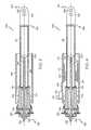
- FIG. 4is a cross-sectional view of an energy harvesting apparatus in accordance with a further embodiment and embodying the principles described above in connection with FIG. 3 .
- a shock absorber 106similar in construction and operation to that shown in FIG. 2 with the exception of the addition of a magnet 170 (e.g. a permanent magnet) fixedly couple to a surface of damper tube 112 , a coil 172 fixedly coupled to a surface of dust tube 146 and, optionally, a rectifier 174 and connector 176 coupled to coil 172 via conductors 178 (only one of which is shown for clarity).
- a magnet 170e.g. a permanent magnet
- a coil 172fixedly coupled to a surface of dust tube 146
- a rectifier 174 and connector 176coupled to coil 172 via conductors 178 (only one of which is shown for clarity).
- magnet 170vibrates back and forth within or in close proximity to coil 172 thus inducing an AC current in coil 172 as previously described in connection with FIG. 3 . If desired, this current may be applied to a rectifier 174 via conductors 178 . The rectified or DC current may then be made available to a storage device (e.g. 162 in FIG. 3 ) and/or made available to the vehicle's electrical system.
- a storage devicee.g. 162 in FIG. 3
- FIG. 5is a cross-sectional view of an energy harvesting apparatus in accordance with a still further embodiment.
- magnet 170is now fixedly coupled to an inner surface of dust tube 146
- coil 172is mounted on an outer surface of damper tube 112 .
- rectifier 174 and connector 176may now be coupled to the surface of damper tube 112 via conductor 178 as shown.
- the operation of the system shown in FIG. 5is similar to that previously described in connection with FIGS. 3 and 4 . In this case, however, coil 172 oscillates in the vicinity of magnet 170 to induce a current in coil 172 .
- FIG. 6is a block diagram of a rectifier circuit 182 suitable for use in conjunction with the embodiment shown in FIGS. 3 , 4 and 5 .
- FIGS. 7 , 8 , and 9illustrate exemplary waveforms 184 , 188 , and 192 that appear at various places in the block diagram shown in FIG. 6 as will be more fully described below.
- the AC signal ( 184 in FIG. 7 ) appearing at the outputs of coil 156 ( FIG. 3 )is applied to full wave rectifier 186 .
- the rectified signal 188 (shown in FIG. 8 ) appearing at the output of rectifier 186is applied to low pass filter 190 to produce waveform 192 (shown in FIG. 9 ).
- the battery or capacitorcould be packaged with the rectifier or packaged separately.
- the rectifier assemblycould be mounted on the damper or on a separate structure, and the shock absorber may be passive or electronically controlled.
- the energy harvesting apparatusmay be employed with a linear actuator used in active or semi-active control systems, lifting gate strut assemblies, and the like.
Landscapes
- Engineering & Computer Science (AREA)
- Power Engineering (AREA)
- Vehicle Body Suspensions (AREA)
- Fluid-Damping Devices (AREA)
- Vibration Prevention Devices (AREA)
Abstract
Description
Claims (9)
Priority Applications (2)
| Application Number | Priority Date | Filing Date | Title |
|---|---|---|---|
| US12/394,328US8253281B2 (en) | 2009-02-27 | 2009-02-27 | Energy harvesting apparatus incorporated into shock absorber |
| DE102010008318ADE102010008318A1 (en) | 2009-02-27 | 2010-02-17 | Energy production from vehicle vibrations |
Applications Claiming Priority (1)
| Application Number | Priority Date | Filing Date | Title |
|---|---|---|---|
| US12/394,328US8253281B2 (en) | 2009-02-27 | 2009-02-27 | Energy harvesting apparatus incorporated into shock absorber |
Publications (2)
| Publication Number | Publication Date |
|---|---|
| US20100219798A1 US20100219798A1 (en) | 2010-09-02 |
| US8253281B2true US8253281B2 (en) | 2012-08-28 |
Family
ID=42666754
Family Applications (1)
| Application Number | Title | Priority Date | Filing Date |
|---|---|---|---|
| US12/394,328Expired - Fee RelatedUS8253281B2 (en) | 2009-02-27 | 2009-02-27 | Energy harvesting apparatus incorporated into shock absorber |
Country Status (2)
| Country | Link |
|---|---|
| US (1) | US8253281B2 (en) |
| DE (1) | DE102010008318A1 (en) |
Cited By (31)
| Publication number | Priority date | Publication date | Assignee | Title |
|---|---|---|---|---|
| US20100244457A1 (en)* | 2009-03-25 | 2010-09-30 | Bhat Nikhil | Energy harvesting system |
| US20110032103A1 (en)* | 2009-08-07 | 2011-02-10 | Bhat Nikhil | Motion detection system |
| US20130049492A1 (en)* | 2008-12-10 | 2013-02-28 | Juan Andujar | System for Converting Tidal Wave Energy Into Electric Energy |
| DE102013209209A1 (en)* | 2013-05-17 | 2014-11-20 | BSH Bosch und Siemens Hausgeräte GmbH | Home appliance with energy recovery and method for recovering energy in a household appliance |
| US20150015352A1 (en)* | 2012-06-19 | 2015-01-15 | Kayaba Industry Co., Ltd. | Linear actuator and groove fashioning method for linear actuator |
| US20150069683A1 (en)* | 2009-04-22 | 2015-03-12 | Dynamic Energy Technologies, Llc | Kinetic Energy Management System |
| US9088187B2 (en) | 2011-10-28 | 2015-07-21 | Juan Andujar | Hybrid electro magnetic hydro kinetic high pressure propulsion generator |
| US20150224845A1 (en)* | 2013-03-15 | 2015-08-13 | Levant Power Corporation | Active vehicle suspension system |
| US9597939B2 (en) | 2008-04-17 | 2017-03-21 | ClearMotion, Inc. | Hydraulic energy transfer |
| US9669713B2 (en) | 2014-03-05 | 2017-06-06 | Nissan North America, Inc. | Vehicle with an auxiliary power pack |
| US9694639B2 (en) | 2013-03-15 | 2017-07-04 | ClearMotion, Inc. | Distributed active suspension control system |
| US9702424B2 (en) | 2014-10-06 | 2017-07-11 | ClearMotion, Inc. | Hydraulic damper, hydraulic bump-stop and diverter valve |
| US9718370B2 (en) | 2011-04-22 | 2017-08-01 | Angel A. Penilla | Methods and systems for electric vehicle (EV) charging and cloud remote access and user notifications |
| US10053210B2 (en)* | 2015-02-18 | 2018-08-21 | Messier-Bugatti-Dowty | Aircraft undercarriage including a telescopic linear rod |
| US10589591B2 (en) | 2018-02-23 | 2020-03-17 | Tenneco Automotive Operating Company Inc. | Active damper system actuator arrangement |
| US10690215B2 (en) | 2018-02-23 | 2020-06-23 | Tenneco Automotive Operating Company Inc. | Damper with electro-magnetic actuator |
| US10767557B1 (en) | 2017-03-10 | 2020-09-08 | Ladan Behnia | Gas-assisted air turbine system for generating electricity |
| CN112187004A (en)* | 2020-10-15 | 2021-01-05 | 苏州索迩电子技术有限公司 | Broadband motor |
| US11047446B2 (en)* | 2018-07-03 | 2021-06-29 | Ab Elektronik Gmbh | Shock absorber with position sensor |
| US11161402B2 (en) | 2019-05-20 | 2021-11-02 | Canoo Technologies Inc. | Electric vehicle platform |
| US11251494B2 (en) | 2019-09-20 | 2022-02-15 | Canoo Technologies Inc. | Electric vehicle battery enclosure |
| US11290032B1 (en) | 2021-07-22 | 2022-03-29 | Gonzalo Fuentes Iriarte | Systems and methods for electric vehicle energy recovery |
| US11318995B2 (en) | 2019-07-02 | 2022-05-03 | Canoo Technologies Inc. | Impact features |
| US11338637B2 (en) | 2019-01-28 | 2022-05-24 | Tenneco Automotive Operating Company Inc. | Electro-magnetic damper with air spring |
| US11391338B2 (en)* | 2017-10-18 | 2022-07-19 | Hitachi Astemo, Ltd. | Shock absorber |
| US11592324B2 (en) | 2018-06-06 | 2023-02-28 | Prominent Gmbh | Dosing pump with linear motor |
| US11607977B2 (en) | 2019-09-20 | 2023-03-21 | Canoo Technologies Inc. | Vehicle seating systems |
| US11618292B2 (en) | 2019-09-09 | 2023-04-04 | Canoo Technologies Inc. | Suspension system |
| US11742540B2 (en) | 2019-01-07 | 2023-08-29 | Canoo Technologies Inc. | Methods and systems for battery pack thermal management |
| US12345241B2 (en) | 2020-11-06 | 2025-07-01 | Ashot Salvaryan | Regenerative energy system using direct kinetic energy transfer to a generator |
| US12420869B2 (en) | 2019-07-02 | 2025-09-23 | Canoo Technologies Inc. | Method to reduced lateral deflection of longitudinal members in side impact |
Families Citing this family (18)
| Publication number | Priority date | Publication date | Assignee | Title |
|---|---|---|---|---|
| US8160774B2 (en)* | 2008-10-15 | 2012-04-17 | GM Global Technology Operations LLC | Vehicular actuator system |
| US8174377B2 (en)* | 2008-11-14 | 2012-05-08 | GM Global Technology Operations LLC | Suspension height sensor |
| US8175770B2 (en)* | 2008-11-17 | 2012-05-08 | GM Global Technology Operations LLC | Height sensing system for a vehicular suspension assembly |
| US7936113B2 (en)* | 2009-02-27 | 2011-05-03 | GM Global Technology Operations LLC | Harvesting energy from vehicular vibrations using piezoelectric devices |
| US8143766B2 (en)* | 2009-02-27 | 2012-03-27 | GM Global Technology Operations LLC | Harvesting energy from vehicular vibrations using piezoelectric devices |
| US8063498B2 (en)* | 2009-02-27 | 2011-11-22 | GM Global Technology Operations LLC | Harvesting energy from vehicular vibrations |
| US7956797B2 (en)* | 2009-03-09 | 2011-06-07 | GM Global Technology Operations LLC | System and method for measuring a relative distance between vehicle components using ultra-wideband techniques |
| US8614518B2 (en)* | 2009-10-14 | 2013-12-24 | GM Global Technology Operations LLC | Self-powered vehicle sensor systems |
| US8534058B2 (en)* | 2010-05-14 | 2013-09-17 | Southwest Research Institute | Energy storage and production systems, apparatus and methods of use thereof |
| US9157421B2 (en) | 2011-04-13 | 2015-10-13 | Abc Nationwide, Inc. | Roadway energy harvesting system |
| US20130033131A1 (en)* | 2011-08-04 | 2013-02-07 | Atlantic Industries, Inc. | Inductive Energy Converter |
| WO2013034760A1 (en)* | 2011-09-09 | 2013-03-14 | Ivan Dreznjak | Electronic parking assistance system |
| DE102011057062A1 (en)* | 2011-12-27 | 2013-06-27 | iOLS GmbH | vehicle |
| DE102012101341B4 (en)* | 2012-02-20 | 2014-08-21 | Asutec Gmbh | Stop device with linear motor |
| US9989076B2 (en) | 2012-11-05 | 2018-06-05 | Indian Institute Of Technology Madras | Mechanical energy harvesting devices and methods |
| CN104319973B (en)* | 2012-12-05 | 2016-08-17 | 河海大学常州校区 | A kind of wave energy generator |
| US9689381B2 (en) | 2012-12-26 | 2017-06-27 | Yanir NULMAN | Method and apparatus for recovery of parasitic energy losses |
| WO2022046969A1 (en)* | 2020-08-26 | 2022-03-03 | Propitious Technologies, Llc | Magnified linear power generation system |
Citations (96)
| Publication number | Priority date | Publication date | Assignee | Title |
|---|---|---|---|---|
| US2594755A (en)* | 1951-07-11 | 1952-04-29 | Brown & Bigelow | Liquefied petroleum gas lighter |
| US3770290A (en)* | 1972-01-24 | 1973-11-06 | F Bottalico | Vehicle shock absorber |
| US3984707A (en)* | 1973-07-13 | 1976-10-05 | Mcclintock Richard D | Spring return linear signal generator |
| US4297609A (en) | 1979-04-06 | 1981-10-27 | Matsushita Electric Industrial Co., Ltd. | High-voltage generating device |
| GB2098007A (en) | 1981-04-30 | 1982-11-10 | Itt Ind Ltd | Electrical generators |
| US4458234A (en) | 1981-05-14 | 1984-07-03 | Brisard Gerard J | On-board apparatus for monitoring the condition of shock absorbers |
| JPS60101425A (en) | 1983-11-09 | 1985-06-05 | Matsushita Electric Ind Co Ltd | High voltage generator |
| US4600215A (en) | 1984-02-29 | 1986-07-15 | Nissan Motor Company, Limited | Vehicular suspension control system with variable damping characteristics depending upon road condition and vehicle speed |
| FR2594755A3 (en) | 1986-02-24 | 1987-08-28 | Marelli Autronica | Device for driving via a piezoelectric transducer the displacements of a movable element forming part of a telescopic shock absorber with respect to a fixed part |
| US4757315A (en) | 1986-02-20 | 1988-07-12 | The United States Of America As Represented By The Administrator Of The National Aeronautics And Space Administration | Method and apparatus for measuring distance |
| US4817922A (en) | 1987-10-23 | 1989-04-04 | The Goodyear Tire & Rubber Company | Airspring height sensor |
| US4822063A (en) | 1987-11-27 | 1989-04-18 | Ford Motor Company | Automotive suspension control system including suspension position sensor |
| US4827416A (en) | 1985-09-13 | 1989-05-02 | Nissan Motor Company, Limited | Method and system for controlling automotive suspension system, particularly for controlling suspension characteristics in accordance with road surface conditions |
| US4836578A (en) | 1987-12-28 | 1989-06-06 | Ford Motor Company | High resolution digital suspension position sensor for automotive vehicle |
| DE3909190C1 (en) | 1989-03-21 | 1990-08-30 | August Bilstein Gmbh & Co Kg, 5828 Ennepetal, De | |
| US5056913A (en) | 1989-09-21 | 1991-10-15 | Stanley Electric Corporation | Optical gauging apparatus |
| US5103396A (en) | 1989-05-15 | 1992-04-07 | Fuji Jukogyo Kabushiki Kaisha | System for controlling active suspensions of a vehicle |
| US5127667A (en) | 1989-11-13 | 1992-07-07 | Matsushita Electric Industrial Co., Ltd. | Suspension control apparatus |
| US5218308A (en) | 1991-04-15 | 1993-06-08 | August Bilstein Gmbh & Co. Kg | Sensor for and method of detecting the position of a piston inside the cylinder of a dashpot |
| US5251729A (en) | 1991-12-20 | 1993-10-12 | General Motors Corporation | Vehicle suspension damper with relative velocity sensor having controlled flux path |
| US5267466A (en) | 1991-09-26 | 1993-12-07 | Ford Motor Co. | Apparatus and method for calibrating a suspension control module |
| US5347186A (en)* | 1992-05-26 | 1994-09-13 | Mcq Associates, Inc. | Linear motion electric power generator |
| US5373445A (en) | 1992-03-05 | 1994-12-13 | Ford Motor Company | Method and apparatus for determining dynamic force within an air spring suspension |
| US5390949A (en) | 1993-03-08 | 1995-02-21 | The University Of Toledo | Active suspension systems and components using piezoelectric sensing and actuation devices |
| US5450322A (en) | 1990-06-19 | 1995-09-12 | Mitsubishi Jidosha Kogyo Kabushiki Kaisha | Suspension control system for automotive vehicle |
| US5461564A (en) | 1994-08-09 | 1995-10-24 | Ford Motor Company | Apparatus and method for calibrating vehicle ride height |
| DE29518322U1 (en) | 1995-11-18 | 1996-01-11 | Götz, Friedrich, 75059 Zaisenhausen | Shock absorber with integrated linear generator for power generation |
| US5638927A (en) | 1995-09-18 | 1997-06-17 | General Motors Corporation | Suspension damper |
| US5944763A (en) | 1995-10-04 | 1999-08-31 | Unisia Jecs Corporation | Control apparatus and method for vehicular suspension system |
| US5973422A (en)* | 1998-07-24 | 1999-10-26 | The Guitammer Company | Low frequency vibrator |
| US5990441A (en) | 1997-12-08 | 1999-11-23 | General Motors Corporation | Damper tube closure |
| US6069581A (en) | 1998-02-20 | 2000-05-30 | Amerigon | High performance vehicle radar system |
| US6111375A (en)* | 1996-01-19 | 2000-08-29 | Zenobi; Carlo Alberto | Apparatus for regenerating energy from the dynamic interactions between ground and running vehicles |
| US6209691B1 (en) | 1998-08-04 | 2001-04-03 | General Motors Corporation | Suspension damper with self-aligning rebound cut-off |
| US6234654B1 (en) | 1998-04-27 | 2001-05-22 | Denso Corporation | Height sensor and vehicular headlight beam axis leveling apparatus |
| US6328144B1 (en) | 1998-11-18 | 2001-12-11 | Honda Giken Kogyo Kabushiki Kaisha | Inverted type of vehicular damper with vehicle height adjusting function |
| US20020032508A1 (en) | 2000-07-31 | 2002-03-14 | Toru Uchino | Suspension control system |
| US6427812B2 (en) | 1997-07-08 | 2002-08-06 | Active Control Experts, Inc. | Damper and valve |
| US6502837B1 (en) | 1998-11-11 | 2003-01-07 | Kenmar Company Trust | Enhanced computer optimized adaptive suspension system and method |
| US20030034697A1 (en)* | 2001-05-07 | 2003-02-20 | Goldner Ronald B. | Electromagnetic linear generator and shock absorber |
| US6614239B2 (en) | 2001-01-19 | 2003-09-02 | Comau Spa | Process and system for measuring the distance of a moving body from a fixed part |
| US6694856B1 (en) | 2001-02-22 | 2004-02-24 | The University Of Maryland | Magnetorheological damper and energy dissipation method |
| US6771007B2 (en) | 2002-04-17 | 2004-08-03 | The Boeing Company | Vibration induced perpetual energy resource |
| US6866127B2 (en) | 2002-08-21 | 2005-03-15 | Delphi Technologies, Inc. | Piston damper assembly, and dust tube subassembly, having a velocity sensor |
| US20050077692A1 (en) | 2003-09-26 | 2005-04-14 | Fumiharu Ogawa | Suspension control system and suspension control method for vehicle |
| US20050090956A1 (en) | 2003-10-03 | 2005-04-28 | Fumiharu Ogawa | Vehicle suspension control system and suspension control method |
| DE10358764A1 (en) | 2003-12-12 | 2005-07-28 | Zf Friedrichshafen Ag | chassis component |
| DE102004010229A1 (en) | 2004-02-26 | 2005-09-22 | Horst Forster | Spring device for voltage generation in vehicles has separated permanent magnet and induction coil with spring oscillation cutting magnetic field and generating voltage |
| US20050270221A1 (en) | 2004-06-03 | 2005-12-08 | Dmitry Fedotov | Ultra-wideband transceiver |
| US7057330B2 (en) | 2003-12-18 | 2006-06-06 | Palo Alto Research Center Incorporated | Broad frequency band energy scavenger |
| US20060176158A1 (en) | 2005-01-27 | 2006-08-10 | Trw Vehicle Safety Systems Inc. | Energy harvesting vehicle condition sensing system |
| US20060188120A1 (en)* | 2005-02-23 | 2006-08-24 | Michael Fisher | Multiple active coil speaker |
| US20060186586A1 (en) | 2005-02-18 | 2006-08-24 | Soles Peter J | Air spring and jounce shock assembly |
| DE102005008403A1 (en) | 2005-02-24 | 2006-09-14 | Knorr-Bremse Systeme für Nutzfahrzeuge GmbH | Sensor device for measuring the compression travel and / or the compression speed of wheels and / or axles of vehicles |
| US20060220330A1 (en)* | 2005-03-31 | 2006-10-05 | Urquidi Carlos A | Vibration isolating bushing with embedded speed/position sensor |
| US7123351B1 (en) | 2002-08-20 | 2006-10-17 | Schaefer Philip R | Method and apparatus for measuring distances using light |
| US20060271678A1 (en) | 2005-05-30 | 2006-11-30 | Rambus, Inc. | Self-powered devices and methods |
| US20070032913A1 (en) | 2005-08-04 | 2007-02-08 | Ghoneim Youssef A | Method and system for dynamic automotive vehicle moding |
| US7221437B1 (en) | 2002-08-20 | 2007-05-22 | Schaefer Philip R | Method and apparatus for measuring distances using light |
| US20070129865A1 (en) | 2005-12-02 | 2007-06-07 | Mando Corporation | Vehicle height controlling suspension apparatus having signal-freeze determining function and vehicle height control method thereof |
| US7250697B2 (en)* | 2003-12-12 | 2007-07-31 | Beaulieu Gerald | Linear generator apparatus |
| US7261171B2 (en) | 2005-10-24 | 2007-08-28 | Towertech Research Group | Apparatus and method for converting movements of a vehicle wheel to electricity for charging a battery of the vehicle |
| US20070205881A1 (en) | 2000-09-08 | 2007-09-06 | Automotive Technologies International, Inc. | Energy Harvesting Systems and Methods for Vehicles |
| US20070236098A1 (en)* | 2006-04-10 | 2007-10-11 | Denso Corporation | Vehicle alternator |
| US20070247011A1 (en)* | 2006-04-21 | 2007-10-25 | Denso Corporation | Automotive tandem alternator having reduced axial length and improved structure for effectively dissipating heat generated by rectifiers |
| US20070251776A1 (en) | 2006-04-26 | 2007-11-01 | Sigmund Braun | Damper |
| US20080116849A1 (en) | 2006-11-22 | 2008-05-22 | Johnston Timothy P | Movement powered headset |
| US7380800B2 (en) | 2005-06-16 | 2008-06-03 | Chrysler Llc | Method and system for controlling a dual mode vehicle suspension system |
| US7420462B2 (en) | 2006-01-23 | 2008-09-02 | Bfs Diversified Products, Llc | Air spring distance indicating system and method |
| US20080238268A1 (en)* | 2007-04-02 | 2008-10-02 | Denso Corporation | Brushless automotive alternator having easily-replaceable protective resistor |
| US20080252174A1 (en) | 2007-04-10 | 2008-10-16 | Advanced Cerametrics, Inc. | Energy harvesting from multiple piezoelectric sources |
| US20080277939A1 (en) | 2004-03-15 | 2008-11-13 | Georgia Tech Research Corporation | Linear Generator and System to Capture Energy from Irregular Linear Movement |
| US20090045698A1 (en) | 2005-04-27 | 2009-02-19 | Drexel University | Piezoelectric powered vehicles and motors |
| US7521841B2 (en) | 2003-07-30 | 2009-04-21 | The Boeing Company | Strain energy shuttle apparatus and method for vibration energy harvesting |
| JP4359901B1 (en) | 2008-09-19 | 2009-11-11 | 有限会社 加納 | Power generator |
| US20090278927A1 (en) | 2008-05-07 | 2009-11-12 | Yutaka Ishiyama | Sensor and apparatus for vehicle height measurement |
| US7654370B2 (en) | 2007-02-02 | 2010-02-02 | Arvin Technologies, Inc. | Shock absorber with integrated position sensor |
| US20100045143A1 (en) | 2007-01-24 | 2010-02-25 | Jean-Frederic Martin | Self-contained piezoelectric device for generating voltage |
| US20100052475A1 (en) | 2008-08-06 | 2010-03-04 | Hyundai Motor Company | Energy Regeneration Device for Suspension System |
| US20100084947A1 (en) | 2008-10-02 | 2010-04-08 | Korea Institute Of Science And Technology | High Efficiency Piezoelectric Energy Harvester Having Spiral Structure |
| US20100094503A1 (en) | 2008-10-15 | 2010-04-15 | Gm Global Technology Operations, Inc. | Vehicular actuator system |
| US20100123568A1 (en) | 2008-11-14 | 2010-05-20 | Gm Global Technology Operations, Inc. | Suspension height sensor |
| US20100125389A1 (en) | 2008-11-17 | 2010-05-20 | Gm Global Technology Operations, Inc. | Height sensing system for a vehicular suspension assembly |
| US7733239B2 (en) | 2006-05-08 | 2010-06-08 | Bfs Diversified Products, Llc | Distance determining system and method |
| US7737608B2 (en) | 2003-07-30 | 2010-06-15 | The Boeing Company | Enhanced amplitude piezoelectric motor apparatus and method |
| US7770701B1 (en) | 2003-02-24 | 2010-08-10 | Horstman, Inc. | Suspension strut for use with a compressible magnetorheological fluid |
| US7777396B2 (en) | 2006-06-06 | 2010-08-17 | Omnitek Partners Llc | Impact powered devices |
| US20100219721A1 (en) | 2009-02-27 | 2010-09-02 | Gm Global Technology Operations, Inc. | Harvesting energy from vehicular vibrations using piezoelectric devices |
| US20100219720A1 (en) | 2009-02-27 | 2010-09-02 | Gm Global Technology Operations, Inc. | Harvesting energy from vehicular vibrations using piezoelectric devices |
| US20100219641A1 (en) | 2009-02-27 | 2010-09-02 | Gm Global Technology Operations, Inc. | Harvesting energy from vehicular vibrations |
| US20100225527A1 (en) | 2009-03-09 | 2010-09-09 | Gm Global Technology Operations, Inc. | System and method for measuring a relative distance between vehicle components using ultra-wideband techniques |
| US20100244629A1 (en) | 2009-03-31 | 2010-09-30 | Ceratec Corporation | Piezoelectric Generator |
| US7839058B1 (en) | 2007-01-29 | 2010-11-23 | Microstrain, Inc. | Wideband vibration energy harvester |
| US7849983B2 (en) | 2006-05-01 | 2010-12-14 | Lord Corporation | Controllable vehicle suspension system with a controllable magnetorheological fluid strut |
| US7938410B2 (en)* | 2006-09-15 | 2011-05-10 | Toyota Jidosha Kabushiki Kaisha | Suspension system for vehicle |
| US7948613B2 (en) | 2005-10-07 | 2011-05-24 | Commissariat A L'energie Atomique | Optical device for measuring moving speed of an object relative to a surface |
- 2009
- 2009-02-27USUS12/394,328patent/US8253281B2/ennot_activeExpired - Fee Related
- 2010
- 2010-02-17DEDE102010008318Apatent/DE102010008318A1/ennot_activeWithdrawn
Patent Citations (101)
| Publication number | Priority date | Publication date | Assignee | Title |
|---|---|---|---|---|
| US2594755A (en)* | 1951-07-11 | 1952-04-29 | Brown & Bigelow | Liquefied petroleum gas lighter |
| US3770290A (en)* | 1972-01-24 | 1973-11-06 | F Bottalico | Vehicle shock absorber |
| US3984707A (en)* | 1973-07-13 | 1976-10-05 | Mcclintock Richard D | Spring return linear signal generator |
| US4297609A (en) | 1979-04-06 | 1981-10-27 | Matsushita Electric Industrial Co., Ltd. | High-voltage generating device |
| GB2098007A (en) | 1981-04-30 | 1982-11-10 | Itt Ind Ltd | Electrical generators |
| US4458234A (en) | 1981-05-14 | 1984-07-03 | Brisard Gerard J | On-board apparatus for monitoring the condition of shock absorbers |
| JPS60101425A (en) | 1983-11-09 | 1985-06-05 | Matsushita Electric Ind Co Ltd | High voltage generator |
| US4600215A (en) | 1984-02-29 | 1986-07-15 | Nissan Motor Company, Limited | Vehicular suspension control system with variable damping characteristics depending upon road condition and vehicle speed |
| US4827416A (en) | 1985-09-13 | 1989-05-02 | Nissan Motor Company, Limited | Method and system for controlling automotive suspension system, particularly for controlling suspension characteristics in accordance with road surface conditions |
| US4757315A (en) | 1986-02-20 | 1988-07-12 | The United States Of America As Represented By The Administrator Of The National Aeronautics And Space Administration | Method and apparatus for measuring distance |
| FR2594755A3 (en) | 1986-02-24 | 1987-08-28 | Marelli Autronica | Device for driving via a piezoelectric transducer the displacements of a movable element forming part of a telescopic shock absorber with respect to a fixed part |
| US4817922A (en) | 1987-10-23 | 1989-04-04 | The Goodyear Tire & Rubber Company | Airspring height sensor |
| US4822063A (en) | 1987-11-27 | 1989-04-18 | Ford Motor Company | Automotive suspension control system including suspension position sensor |
| US4836578A (en) | 1987-12-28 | 1989-06-06 | Ford Motor Company | High resolution digital suspension position sensor for automotive vehicle |
| DE3909190C1 (en) | 1989-03-21 | 1990-08-30 | August Bilstein Gmbh & Co Kg, 5828 Ennepetal, De | |
| US5009450A (en) | 1989-03-21 | 1991-04-23 | August Bilstein Gmbh & Co. Kg | Vibration-absorber sensor for a semi-actively controlled chasis with a relative-velocity sensor and with electronics for processing their outputs |
| US5103396A (en) | 1989-05-15 | 1992-04-07 | Fuji Jukogyo Kabushiki Kaisha | System for controlling active suspensions of a vehicle |
| US5056913A (en) | 1989-09-21 | 1991-10-15 | Stanley Electric Corporation | Optical gauging apparatus |
| US5127667A (en) | 1989-11-13 | 1992-07-07 | Matsushita Electric Industrial Co., Ltd. | Suspension control apparatus |
| US5450322A (en) | 1990-06-19 | 1995-09-12 | Mitsubishi Jidosha Kogyo Kabushiki Kaisha | Suspension control system for automotive vehicle |
| US5218308A (en) | 1991-04-15 | 1993-06-08 | August Bilstein Gmbh & Co. Kg | Sensor for and method of detecting the position of a piston inside the cylinder of a dashpot |
| DE4112276C2 (en) | 1991-04-15 | 1993-09-09 | August Bilstein Gmbh & Co Kg, 58256 Ennepetal, De | |
| US5267466A (en) | 1991-09-26 | 1993-12-07 | Ford Motor Co. | Apparatus and method for calibrating a suspension control module |
| US5251729A (en) | 1991-12-20 | 1993-10-12 | General Motors Corporation | Vehicle suspension damper with relative velocity sensor having controlled flux path |
| US5373445A (en) | 1992-03-05 | 1994-12-13 | Ford Motor Company | Method and apparatus for determining dynamic force within an air spring suspension |
| US5347186A (en)* | 1992-05-26 | 1994-09-13 | Mcq Associates, Inc. | Linear motion electric power generator |
| US5390949A (en) | 1993-03-08 | 1995-02-21 | The University Of Toledo | Active suspension systems and components using piezoelectric sensing and actuation devices |
| US5461564A (en) | 1994-08-09 | 1995-10-24 | Ford Motor Company | Apparatus and method for calibrating vehicle ride height |
| US5638927A (en) | 1995-09-18 | 1997-06-17 | General Motors Corporation | Suspension damper |
| US5944763A (en) | 1995-10-04 | 1999-08-31 | Unisia Jecs Corporation | Control apparatus and method for vehicular suspension system |
| DE29518322U1 (en) | 1995-11-18 | 1996-01-11 | Götz, Friedrich, 75059 Zaisenhausen | Shock absorber with integrated linear generator for power generation |
| US6111375A (en)* | 1996-01-19 | 2000-08-29 | Zenobi; Carlo Alberto | Apparatus for regenerating energy from the dynamic interactions between ground and running vehicles |
| US6427812B2 (en) | 1997-07-08 | 2002-08-06 | Active Control Experts, Inc. | Damper and valve |
| US5990441A (en) | 1997-12-08 | 1999-11-23 | General Motors Corporation | Damper tube closure |
| US6069581A (en) | 1998-02-20 | 2000-05-30 | Amerigon | High performance vehicle radar system |
| US6234654B1 (en) | 1998-04-27 | 2001-05-22 | Denso Corporation | Height sensor and vehicular headlight beam axis leveling apparatus |
| US5973422A (en)* | 1998-07-24 | 1999-10-26 | The Guitammer Company | Low frequency vibrator |
| US6209691B1 (en) | 1998-08-04 | 2001-04-03 | General Motors Corporation | Suspension damper with self-aligning rebound cut-off |
| US6502837B1 (en) | 1998-11-11 | 2003-01-07 | Kenmar Company Trust | Enhanced computer optimized adaptive suspension system and method |
| US6328144B1 (en) | 1998-11-18 | 2001-12-11 | Honda Giken Kogyo Kabushiki Kaisha | Inverted type of vehicular damper with vehicle height adjusting function |
| US20020032508A1 (en) | 2000-07-31 | 2002-03-14 | Toru Uchino | Suspension control system |
| US20070205881A1 (en) | 2000-09-08 | 2007-09-06 | Automotive Technologies International, Inc. | Energy Harvesting Systems and Methods for Vehicles |
| US6614239B2 (en) | 2001-01-19 | 2003-09-02 | Comau Spa | Process and system for measuring the distance of a moving body from a fixed part |
| US6694856B1 (en) | 2001-02-22 | 2004-02-24 | The University Of Maryland | Magnetorheological damper and energy dissipation method |
| US20030034697A1 (en)* | 2001-05-07 | 2003-02-20 | Goldner Ronald B. | Electromagnetic linear generator and shock absorber |
| US6771007B2 (en) | 2002-04-17 | 2004-08-03 | The Boeing Company | Vibration induced perpetual energy resource |
| US6938311B2 (en) | 2002-04-17 | 2005-09-06 | The Boeing Company | Method to generate electrical current using a plurality of masses attached to piezoceramic supports |
| US7123351B1 (en) | 2002-08-20 | 2006-10-17 | Schaefer Philip R | Method and apparatus for measuring distances using light |
| US7221437B1 (en) | 2002-08-20 | 2007-05-22 | Schaefer Philip R | Method and apparatus for measuring distances using light |
| US6866127B2 (en) | 2002-08-21 | 2005-03-15 | Delphi Technologies, Inc. | Piston damper assembly, and dust tube subassembly, having a velocity sensor |
| US7770701B1 (en) | 2003-02-24 | 2010-08-10 | Horstman, Inc. | Suspension strut for use with a compressible magnetorheological fluid |
| US7737608B2 (en) | 2003-07-30 | 2010-06-15 | The Boeing Company | Enhanced amplitude piezoelectric motor apparatus and method |
| US7521841B2 (en) | 2003-07-30 | 2009-04-21 | The Boeing Company | Strain energy shuttle apparatus and method for vibration energy harvesting |
| US20050077692A1 (en) | 2003-09-26 | 2005-04-14 | Fumiharu Ogawa | Suspension control system and suspension control method for vehicle |
| US20050090956A1 (en) | 2003-10-03 | 2005-04-28 | Fumiharu Ogawa | Vehicle suspension control system and suspension control method |
| DE10358764A1 (en) | 2003-12-12 | 2005-07-28 | Zf Friedrichshafen Ag | chassis component |
| US20080284258A1 (en) | 2003-12-12 | 2008-11-20 | Joachim Spratte | Chassis Component |
| US7250697B2 (en)* | 2003-12-12 | 2007-07-31 | Beaulieu Gerald | Linear generator apparatus |
| US7057330B2 (en) | 2003-12-18 | 2006-06-06 | Palo Alto Research Center Incorporated | Broad frequency band energy scavenger |
| DE102004010229A1 (en) | 2004-02-26 | 2005-09-22 | Horst Forster | Spring device for voltage generation in vehicles has separated permanent magnet and induction coil with spring oscillation cutting magnetic field and generating voltage |
| US20080277939A1 (en) | 2004-03-15 | 2008-11-13 | Georgia Tech Research Corporation | Linear Generator and System to Capture Energy from Irregular Linear Movement |
| US20050270221A1 (en) | 2004-06-03 | 2005-12-08 | Dmitry Fedotov | Ultra-wideband transceiver |
| US20060176158A1 (en) | 2005-01-27 | 2006-08-10 | Trw Vehicle Safety Systems Inc. | Energy harvesting vehicle condition sensing system |
| US20060186586A1 (en) | 2005-02-18 | 2006-08-24 | Soles Peter J | Air spring and jounce shock assembly |
| US20060188120A1 (en)* | 2005-02-23 | 2006-08-24 | Michael Fisher | Multiple active coil speaker |
| DE102005008403A1 (en) | 2005-02-24 | 2006-09-14 | Knorr-Bremse Systeme für Nutzfahrzeuge GmbH | Sensor device for measuring the compression travel and / or the compression speed of wheels and / or axles of vehicles |
| US20090021720A1 (en) | 2005-02-24 | 2009-01-22 | Knorr-Bremse Systeme für Nutzfahrzeuge GmbH | Sensor device for measuring the compression travel and/or the compression rate of wheels and/or axles of vehicles |
| US20060220330A1 (en)* | 2005-03-31 | 2006-10-05 | Urquidi Carlos A | Vibration isolating bushing with embedded speed/position sensor |
| US20090045698A1 (en) | 2005-04-27 | 2009-02-19 | Drexel University | Piezoelectric powered vehicles and motors |
| US20060271678A1 (en) | 2005-05-30 | 2006-11-30 | Rambus, Inc. | Self-powered devices and methods |
| US7380800B2 (en) | 2005-06-16 | 2008-06-03 | Chrysler Llc | Method and system for controlling a dual mode vehicle suspension system |
| US20070032913A1 (en) | 2005-08-04 | 2007-02-08 | Ghoneim Youssef A | Method and system for dynamic automotive vehicle moding |
| US7948613B2 (en) | 2005-10-07 | 2011-05-24 | Commissariat A L'energie Atomique | Optical device for measuring moving speed of an object relative to a surface |
| US7261171B2 (en) | 2005-10-24 | 2007-08-28 | Towertech Research Group | Apparatus and method for converting movements of a vehicle wheel to electricity for charging a battery of the vehicle |
| US20070129865A1 (en) | 2005-12-02 | 2007-06-07 | Mando Corporation | Vehicle height controlling suspension apparatus having signal-freeze determining function and vehicle height control method thereof |
| US7420462B2 (en) | 2006-01-23 | 2008-09-02 | Bfs Diversified Products, Llc | Air spring distance indicating system and method |
| US20070236098A1 (en)* | 2006-04-10 | 2007-10-11 | Denso Corporation | Vehicle alternator |
| US20070247011A1 (en)* | 2006-04-21 | 2007-10-25 | Denso Corporation | Automotive tandem alternator having reduced axial length and improved structure for effectively dissipating heat generated by rectifiers |
| US20070251776A1 (en) | 2006-04-26 | 2007-11-01 | Sigmund Braun | Damper |
| US7849983B2 (en) | 2006-05-01 | 2010-12-14 | Lord Corporation | Controllable vehicle suspension system with a controllable magnetorheological fluid strut |
| US7733239B2 (en) | 2006-05-08 | 2010-06-08 | Bfs Diversified Products, Llc | Distance determining system and method |
| US7777396B2 (en) | 2006-06-06 | 2010-08-17 | Omnitek Partners Llc | Impact powered devices |
| US7938410B2 (en)* | 2006-09-15 | 2011-05-10 | Toyota Jidosha Kabushiki Kaisha | Suspension system for vehicle |
| US20080116849A1 (en) | 2006-11-22 | 2008-05-22 | Johnston Timothy P | Movement powered headset |
| US20100045143A1 (en) | 2007-01-24 | 2010-02-25 | Jean-Frederic Martin | Self-contained piezoelectric device for generating voltage |
| US7839058B1 (en) | 2007-01-29 | 2010-11-23 | Microstrain, Inc. | Wideband vibration energy harvester |
| US7654370B2 (en) | 2007-02-02 | 2010-02-02 | Arvin Technologies, Inc. | Shock absorber with integrated position sensor |
| US20080238268A1 (en)* | 2007-04-02 | 2008-10-02 | Denso Corporation | Brushless automotive alternator having easily-replaceable protective resistor |
| US20080252174A1 (en) | 2007-04-10 | 2008-10-16 | Advanced Cerametrics, Inc. | Energy harvesting from multiple piezoelectric sources |
| US20090278927A1 (en) | 2008-05-07 | 2009-11-12 | Yutaka Ishiyama | Sensor and apparatus for vehicle height measurement |
| US20100052475A1 (en) | 2008-08-06 | 2010-03-04 | Hyundai Motor Company | Energy Regeneration Device for Suspension System |
| JP4359901B1 (en) | 2008-09-19 | 2009-11-11 | 有限会社 加納 | Power generator |
| US20100084947A1 (en) | 2008-10-02 | 2010-04-08 | Korea Institute Of Science And Technology | High Efficiency Piezoelectric Energy Harvester Having Spiral Structure |
| US20100094503A1 (en) | 2008-10-15 | 2010-04-15 | Gm Global Technology Operations, Inc. | Vehicular actuator system |
| US20100123568A1 (en) | 2008-11-14 | 2010-05-20 | Gm Global Technology Operations, Inc. | Suspension height sensor |
| US20100125389A1 (en) | 2008-11-17 | 2010-05-20 | Gm Global Technology Operations, Inc. | Height sensing system for a vehicular suspension assembly |
| US20100219641A1 (en) | 2009-02-27 | 2010-09-02 | Gm Global Technology Operations, Inc. | Harvesting energy from vehicular vibrations |
| US20100219720A1 (en) | 2009-02-27 | 2010-09-02 | Gm Global Technology Operations, Inc. | Harvesting energy from vehicular vibrations using piezoelectric devices |
| US20100219721A1 (en) | 2009-02-27 | 2010-09-02 | Gm Global Technology Operations, Inc. | Harvesting energy from vehicular vibrations using piezoelectric devices |
| US20100225527A1 (en) | 2009-03-09 | 2010-09-09 | Gm Global Technology Operations, Inc. | System and method for measuring a relative distance between vehicle components using ultra-wideband techniques |
| US20100244629A1 (en) | 2009-03-31 | 2010-09-30 | Ceratec Corporation | Piezoelectric Generator |
Non-Patent Citations (22)
| Title |
|---|
| Chinese Office Action for Chinese Application No. 200910206391.1 mailed Jan. 19, 2011. |
| German Office Action for German Application No. 10 2009 047 855.8-21 mailed Jan. 21, 2011. |
| German Office Action for German Application No. 10 2009 052 717.6-21 mailed Feb. 16, 2011. |
| German Office Action for German Application No. 10 2010 008 318.6 mailed May 11, 2011. |
| Li, Y., et al. "Self-Powered Vehicle Sensor Systems," U.S. Appl. No. 12/900,707. |
| Namuduri, Chandra S. et al. "Notice of Allowance" mailed Jan. 4, 2011; U.S. Appl. No. 12/394,438, filed Feb. 27, 2009. |
| Notice of Allowance mailed Nov. 18, 2010, issued in U.S. Appl. No. 12/394,438. |
| Notice of Allowance mailed Oct. 8, 2010, issued in U.S. Appl. No. 12/400,112. |
| Notice of Allowance, dated Dec. 12, 2011, for U.S. Appl. No. 12/252,114. |
| Notice of Allowance, dated Jan. 5, 2012, for U.S. Appl. No. 12/271,551. |
| Notice of Allowance, dated Jan. 9, 2012, for U.S. Appl. No. 12/272,074. |
| Notice of Allowance, dated Nov. 16, 2011, for U.S. Appl. No. 12/394,326. |
| Optek Technology, Inc. "OPTEK's Autopad Contactless Sensor Delivers Absolute Position, Angle and Linear Displacement Sensing." [Retrieved on Aug. 11, 2008]. Retrieved from Internet: . |
| Optek Technology, Inc. "OPTEK's Autopad Contactless Sensor Delivers Absolute Position, Angle and Linear Displacement Sensing." [Retrieved on Aug. 11, 2008]. Retrieved from Internet: <URL: http://license.icopyright.net/user/viewFreeUse.act?fuid=MTM4Mjg4MQ%3D%3D>. |
| Samkov, S.V., "Signal Processing in UWB Radars of Small Distance," 2004 Second International Workshop on Ultrawideband and Ultrashort Impulse Signals. Sep. 19-22, 2004, pp. 208-210. |
| Sang-Dong, K., et al., "Performance Analysis of UWB Radar for Vehicle in Multi-User Environments," 10th International Conference on Advanced Communication Technology, ICACT. Feb. 17-20, 2008, pp. 1036-1039, vol. 2. |
| U.S. Final Office Action dated Jul. 15, 2011 for U.S. Appl. No. 12/271,551. |
| U.S. Notice of Allowance dated Jul. 18, 2011 for U.S. Appl. No. 12/394,322. |
| U.S. Office Action dated Aug. 1, 2011 for U.S. Appl. No. 12/272,074. |
| U.S. Office Action dated Jul. 6, 2011 for U.S. Appl. No. 12/252,114. |
| U.S. Office Action dated Jun. 17, 2011 for U.S. Appl. No. 12/394,326. |
| U.S. Office Action for U.S. Appl. No. 12/271,551 mailed Feb. 10, 2011. |
Cited By (51)
| Publication number | Priority date | Publication date | Assignee | Title |
|---|---|---|---|---|
| US9597939B2 (en) | 2008-04-17 | 2017-03-21 | ClearMotion, Inc. | Hydraulic energy transfer |
| US20130049492A1 (en)* | 2008-12-10 | 2013-02-28 | Juan Andujar | System for Converting Tidal Wave Energy Into Electric Energy |
| US8772986B2 (en)* | 2008-12-10 | 2014-07-08 | Juan Andujar | System for converting tidal wave energy into electric energy |
| US8344526B2 (en)* | 2009-03-25 | 2013-01-01 | Bhat Nikhil | Energy generating supports |
| US20100244457A1 (en)* | 2009-03-25 | 2010-09-30 | Bhat Nikhil | Energy harvesting system |
| US20150069683A1 (en)* | 2009-04-22 | 2015-03-12 | Dynamic Energy Technologies, Llc | Kinetic Energy Management System |
| US20110032103A1 (en)* | 2009-08-07 | 2011-02-10 | Bhat Nikhil | Motion detection system |
| US10071643B2 (en) | 2011-04-22 | 2018-09-11 | Emerging Automotive, Llc | Methods and systems for electric vehicle (EV) charging and cloud remote access and user notifications |
| US9802500B1 (en) | 2011-04-22 | 2017-10-31 | Emerging Automotive, Llc | Methods and systems for electric vehicle (EV) charging and cloud remote access and user notifications |
| US9718370B2 (en) | 2011-04-22 | 2017-08-01 | Angel A. Penilla | Methods and systems for electric vehicle (EV) charging and cloud remote access and user notifications |
| US9088187B2 (en) | 2011-10-28 | 2015-07-21 | Juan Andujar | Hybrid electro magnetic hydro kinetic high pressure propulsion generator |
| US9035732B2 (en)* | 2012-06-19 | 2015-05-19 | Kayaba Industry Co., Ltd. | Linear actuator and groove fashioning method for linear actuator |
| US20150015352A1 (en)* | 2012-06-19 | 2015-01-15 | Kayaba Industry Co., Ltd. | Linear actuator and groove fashioning method for linear actuator |
| US9694639B2 (en) | 2013-03-15 | 2017-07-04 | ClearMotion, Inc. | Distributed active suspension control system |
| US20190001782A1 (en)* | 2013-03-15 | 2019-01-03 | ClearMotion, Inc. | Active vehicle suspension system |
| US20210339595A1 (en)* | 2013-03-15 | 2021-11-04 | ClearMotion, Inc. | Active vehicle suspension system |
| US9707814B2 (en) | 2013-03-15 | 2017-07-18 | ClearMotion, Inc. | Active stabilization system for truck cabins |
| US11850905B2 (en)* | 2013-03-15 | 2023-12-26 | ClearMotion, Inc. | Active vehicle suspension system |
| US20150224845A1 (en)* | 2013-03-15 | 2015-08-13 | Levant Power Corporation | Active vehicle suspension system |
| US10040330B2 (en)* | 2013-03-15 | 2018-08-07 | ClearMotion, Inc. | Active vehicle suspension system |
| US20240300275A1 (en)* | 2013-03-15 | 2024-09-12 | ClearMotion, Inc. | Active vehicle suspension system |
| US11021033B2 (en)* | 2013-03-15 | 2021-06-01 | ClearMotion, Inc. | Active vehicle suspension system |
| US9702349B2 (en)* | 2013-03-15 | 2017-07-11 | ClearMotion, Inc. | Active vehicle suspension system |
| US20240391286A1 (en)* | 2013-03-15 | 2024-11-28 | ClearMotion, Inc. | Active vehicle suspension system |
| US12179539B2 (en)* | 2013-03-15 | 2024-12-31 | ClearMotion, Inc. | Active vehicle suspension system |
| DE102013209209A1 (en)* | 2013-05-17 | 2014-11-20 | BSH Bosch und Siemens Hausgeräte GmbH | Home appliance with energy recovery and method for recovering energy in a household appliance |
| US9669713B2 (en) | 2014-03-05 | 2017-06-06 | Nissan North America, Inc. | Vehicle with an auxiliary power pack |
| US9702424B2 (en) | 2014-10-06 | 2017-07-11 | ClearMotion, Inc. | Hydraulic damper, hydraulic bump-stop and diverter valve |
| US10053210B2 (en)* | 2015-02-18 | 2018-08-21 | Messier-Bugatti-Dowty | Aircraft undercarriage including a telescopic linear rod |
| US10767557B1 (en) | 2017-03-10 | 2020-09-08 | Ladan Behnia | Gas-assisted air turbine system for generating electricity |
| US11391338B2 (en)* | 2017-10-18 | 2022-07-19 | Hitachi Astemo, Ltd. | Shock absorber |
| US10589591B2 (en) | 2018-02-23 | 2020-03-17 | Tenneco Automotive Operating Company Inc. | Active damper system actuator arrangement |
| US10690215B2 (en) | 2018-02-23 | 2020-06-23 | Tenneco Automotive Operating Company Inc. | Damper with electro-magnetic actuator |
| US11592324B2 (en) | 2018-06-06 | 2023-02-28 | Prominent Gmbh | Dosing pump with linear motor |
| US11047446B2 (en)* | 2018-07-03 | 2021-06-29 | Ab Elektronik Gmbh | Shock absorber with position sensor |
| US11742540B2 (en) | 2019-01-07 | 2023-08-29 | Canoo Technologies Inc. | Methods and systems for battery pack thermal management |
| US11338637B2 (en) | 2019-01-28 | 2022-05-24 | Tenneco Automotive Operating Company Inc. | Electro-magnetic damper with air spring |
| US12103375B2 (en) | 2019-05-20 | 2024-10-01 | Canoo Technologies Inc. | Electric vehicle platform |
| US11833895B2 (en) | 2019-05-20 | 2023-12-05 | Canoo Technologies Inc. | Electric vehicle platform |
| US11292326B2 (en) | 2019-05-20 | 2022-04-05 | Canoo Technologies Inc. | Electric vehicle platform |
| US11161402B2 (en) | 2019-05-20 | 2021-11-02 | Canoo Technologies Inc. | Electric vehicle platform |
| US12168475B2 (en) | 2019-07-02 | 2024-12-17 | Canoo Technologies Inc. | Impact features |
| US11318995B2 (en) | 2019-07-02 | 2022-05-03 | Canoo Technologies Inc. | Impact features |
| US12420869B2 (en) | 2019-07-02 | 2025-09-23 | Canoo Technologies Inc. | Method to reduced lateral deflection of longitudinal members in side impact |
| US11618292B2 (en) | 2019-09-09 | 2023-04-04 | Canoo Technologies Inc. | Suspension system |
| US11738670B2 (en) | 2019-09-20 | 2023-08-29 | Canoo Technologies Inc. | Vehicle seating systems |
| US11251494B2 (en) | 2019-09-20 | 2022-02-15 | Canoo Technologies Inc. | Electric vehicle battery enclosure |
| US11607977B2 (en) | 2019-09-20 | 2023-03-21 | Canoo Technologies Inc. | Vehicle seating systems |
| CN112187004A (en)* | 2020-10-15 | 2021-01-05 | 苏州索迩电子技术有限公司 | Broadband motor |
| US12345241B2 (en) | 2020-11-06 | 2025-07-01 | Ashot Salvaryan | Regenerative energy system using direct kinetic energy transfer to a generator |
| US11290032B1 (en) | 2021-07-22 | 2022-03-29 | Gonzalo Fuentes Iriarte | Systems and methods for electric vehicle energy recovery |
Also Published As
| Publication number | Publication date |
|---|---|
| US20100219798A1 (en) | 2010-09-02 |
| DE102010008318A1 (en) | 2010-11-04 |
Similar Documents
| Publication | Publication Date | Title |
|---|---|---|
| US8253281B2 (en) | Energy harvesting apparatus incorporated into shock absorber | |
| US8063498B2 (en) | Harvesting energy from vehicular vibrations | |
| US7936113B2 (en) | Harvesting energy from vehicular vibrations using piezoelectric devices | |
| US8941251B2 (en) | Electricity generating shock absorbers | |
| US8614518B2 (en) | Self-powered vehicle sensor systems | |
| CN107606041B (en) | Hybrid damper formed by combining magneto-rheological damper and electric vortex damper | |
| US8616536B2 (en) | Active dynamic vibration absorber apparatus for vehicle | |
| CN108331878B (en) | Series energy feedback type hybrid active suspension actuator and control method thereof | |
| CN207333558U (en) | The type hybrid damper that MR damper and eddy current damper are composed | |
| CN110005747A (en) | An integrated electromagnetic shock absorber | |
| KR101448467B1 (en) | Resonance linear gengrator using vibration of a road surface | |
| CN103192673A (en) | Semi-active suspension energy-regenerative device of hybrid vehicle | |
| CN105378327A (en) | Damper-mounting device | |
| CN205689655U (en) | A kind of electromagnetic shock absorber | |
| CN110481259B (en) | Magnetic gas energy-feedback suspension actuator | |
| CN109899437A (en) | Vibration energy regeneration type magneto-rheological vibration damper | |
| CN207945234U (en) | A Series Feedback Type Hybrid Active Suspension Actuator | |
| Sultoni et al. | Modeling, prototyping and testing of regenerative electromagnetic shock absorber | |
| CN207241341U (en) | A kind of combined type energy feeding back type semi-active suspension actuator | |
| Xu et al. | Damping characteristics of a hydraulic electric rectifier shock absorber and its effect on vehicle dynamics | |
| CN112895833A (en) | Suspension actuator and method for controlling suspension actuator | |
| KR20010011034A (en) | Energy converter for vehicle | |
| CN110486411A (en) | A kind of active damping support device | |
| Sultoni et al. | Vibration energy harvesting on vehicle suspension using rotary and linear electromagnetic generator | |
| US20250075765A1 (en) | Absorber device and damper device |
Legal Events
| Date | Code | Title | Description |
|---|---|---|---|
| AS | Assignment | Owner name:GM GLOBAL TECHNOLOGY OPERATIONS, INC., MICHIGAN Free format text:ASSIGNMENT OF ASSIGNORS INTEREST;ASSIGNORS:NAMUDURI, CHANDRA S.;LI, YUNJUN;TALTY, TIMOTHY J.;AND OTHERS;SIGNING DATES FROM 20090324 TO 20090331;REEL/FRAME:022670/0045 | |
| AS | Assignment | Owner name:UNITED STATES DEPARTMENT OF THE TREASURY, DISTRICT Free format text:SECURITY AGREEMENT;ASSIGNOR:GM GLOBAL TECHNOLOGY OPERATIONS, INC.;REEL/FRAME:023201/0118 Effective date:20090710 | |
| AS | Assignment | Owner name:UAW RETIREE MEDICAL BENEFITS TRUST, MICHIGAN Free format text:SECURITY AGREEMENT;ASSIGNOR:GM GLOBAL TECHNOLOGY OPERATIONS, INC.;REEL/FRAME:023162/0048 Effective date:20090710 | |
| AS | Assignment | Owner name:GM GLOBAL TECHNOLOGY OPERATIONS, INC., MICHIGAN Free format text:RELEASE BY SECURED PARTY;ASSIGNOR:UNITED STATES DEPARTMENT OF THE TREASURY;REEL/FRAME:025246/0056 Effective date:20100420 | |
| AS | Assignment | Owner name:GM GLOBAL TECHNOLOGY OPERATIONS, INC., MICHIGAN Free format text:RELEASE BY SECURED PARTY;ASSIGNOR:UAW RETIREE MEDICAL BENEFITS TRUST;REEL/FRAME:025315/0091 Effective date:20101026 | |
| AS | Assignment | Owner name:WILMINGTON TRUST COMPANY, DELAWARE Free format text:SECURITY AGREEMENT;ASSIGNOR:GM GLOBAL TECHNOLOGY OPERATIONS, INC.;REEL/FRAME:025324/0515 Effective date:20101027 | |
| AS | Assignment | Owner name:GM GLOBAL TECHNOLOGY OPERATIONS LLC, MICHIGAN Free format text:CHANGE OF NAME;ASSIGNOR:GM GLOBAL TECHNOLOGY OPERATIONS, INC.;REEL/FRAME:025781/0245 Effective date:20101202 | |
| FEPP | Fee payment procedure | Free format text:PAYOR NUMBER ASSIGNED (ORIGINAL EVENT CODE: ASPN); ENTITY STATUS OF PATENT OWNER: LARGE ENTITY | |
| ZAAA | Notice of allowance and fees due | Free format text:ORIGINAL CODE: NOA | |
| ZAAB | Notice of allowance mailed | Free format text:ORIGINAL CODE: MN/=. | |
| STCF | Information on status: patent grant | Free format text:PATENTED CASE | |
| AS | Assignment | Owner name:GM GLOBAL TECHNOLOGY OPERATIONS LLC, MICHIGAN Free format text:RELEASE BY SECURED PARTY;ASSIGNOR:WILMINGTON TRUST COMPANY;REEL/FRAME:034185/0789 Effective date:20141017 | |
| FPAY | Fee payment | Year of fee payment:4 | |
| MAFP | Maintenance fee payment | Free format text:PAYMENT OF MAINTENANCE FEE, 8TH YEAR, LARGE ENTITY (ORIGINAL EVENT CODE: M1552); ENTITY STATUS OF PATENT OWNER: LARGE ENTITY Year of fee payment:8 | |
| FEPP | Fee payment procedure | Free format text:MAINTENANCE FEE REMINDER MAILED (ORIGINAL EVENT CODE: REM.); ENTITY STATUS OF PATENT OWNER: LARGE ENTITY | |
| LAPS | Lapse for failure to pay maintenance fees | Free format text:PATENT EXPIRED FOR FAILURE TO PAY MAINTENANCE FEES (ORIGINAL EVENT CODE: EXP.); ENTITY STATUS OF PATENT OWNER: LARGE ENTITY | |
| STCH | Information on status: patent discontinuation | Free format text:PATENT EXPIRED DUE TO NONPAYMENT OF MAINTENANCE FEES UNDER 37 CFR 1.362 | |
| FP | Lapsed due to failure to pay maintenance fee | Effective date:20240828 |