US8252035B2 - Device delivery system with two stage withdrawal - Google Patents
Device delivery system with two stage withdrawalDownload PDFInfo
- Publication number
- US8252035B2 US8252035B2US11/832,002US83200207AUS8252035B2US 8252035 B2US8252035 B2US 8252035B2US 83200207 AUS83200207 AUS 83200207AUS 8252035 B2US8252035 B2US 8252035B2
- Authority
- US
- United States
- Prior art keywords
- sheath
- catheter
- delivery system
- length
- medical device
- Prior art date
- Legal status (The legal status is an assumption and is not a legal conclusion. Google has not performed a legal analysis and makes no representation as to the accuracy of the status listed.)
- Expired - Fee Related, expires
Links
- 238000000034methodMethods0.000claimsdescription10
- 230000000977initiatory effectEffects0.000abstract1
- 230000006870functionEffects0.000description7
- 230000007246mechanismEffects0.000description7
- 239000003292glueSubstances0.000description6
- 239000000463materialSubstances0.000description6
- 239000003550markerSubstances0.000description5
- 210000003484anatomyAnatomy0.000description4
- 229910001000nickel titaniumInorganic materials0.000description4
- 229910052751metalInorganic materials0.000description3
- 239000002184metalSubstances0.000description3
- 210000004204blood vesselAnatomy0.000description2
- 238000010276constructionMethods0.000description2
- 230000008878couplingEffects0.000description2
- 238000010168coupling processMethods0.000description2
- 238000005859coupling reactionMethods0.000description2
- 239000003814drugSubstances0.000description2
- HLXZNVUGXRDIFK-UHFFFAOYSA-Nnickel titaniumChemical compound[Ti].[Ti].[Ti].[Ti].[Ti].[Ti].[Ti].[Ti].[Ti].[Ti].[Ti].[Ni].[Ni].[Ni].[Ni].[Ni].[Ni].[Ni].[Ni].[Ni].[Ni].[Ni].[Ni].[Ni].[Ni]HLXZNVUGXRDIFK-UHFFFAOYSA-N0.000description2
- 208000037803restenosisDiseases0.000description2
- 230000002792vascularEffects0.000description2
- 206010003210ArteriosclerosisDiseases0.000description1
- HZEWFHLRYVTOIW-UHFFFAOYSA-N[Ti].[Ni]Chemical compound[Ti].[Ni]HZEWFHLRYVTOIW-UHFFFAOYSA-N0.000description1
- 238000004026adhesive bondingMethods0.000description1
- 229910045601alloyInorganic materials0.000description1
- 239000000956alloySubstances0.000description1
- 208000011775arteriosclerosis diseaseDiseases0.000description1
- 230000008859changeEffects0.000description1
- 238000002788crimpingMethods0.000description1
- 229940079593drugDrugs0.000description1
- 239000000835fiberSubstances0.000description1
- PCHJSUWPFVWCPO-UHFFFAOYSA-NgoldChemical compound[Au]PCHJSUWPFVWCPO-UHFFFAOYSA-N0.000description1
- 239000010931goldSubstances0.000description1
- 229910052737goldInorganic materials0.000description1
- 238000007373indentationMethods0.000description1
- 150000002739metalsChemical class0.000description1
- 238000012986modificationMethods0.000description1
- 230000004048modificationEffects0.000description1
- 238000000465mouldingMethods0.000description1
- 239000004033plasticSubstances0.000description1
- HWLDNSXPUQTBOD-UHFFFAOYSA-Nplatinum-iridium alloyChemical compound[Ir].[Pt]HWLDNSXPUQTBOD-UHFFFAOYSA-N0.000description1
- 229920000642polymerPolymers0.000description1
- 239000004810polytetrafluoroethyleneSubstances0.000description1
- 229920001343polytetrafluoroethylenePolymers0.000description1
- 230000000452restraining effectEffects0.000description1
- 239000010902strawSubstances0.000description1
- 210000005166vasculatureAnatomy0.000description1
Images


Classifications
- A—HUMAN NECESSITIES
- A61—MEDICAL OR VETERINARY SCIENCE; HYGIENE
- A61F—FILTERS IMPLANTABLE INTO BLOOD VESSELS; PROSTHESES; DEVICES PROVIDING PATENCY TO, OR PREVENTING COLLAPSING OF, TUBULAR STRUCTURES OF THE BODY, e.g. STENTS; ORTHOPAEDIC, NURSING OR CONTRACEPTIVE DEVICES; FOMENTATION; TREATMENT OR PROTECTION OF EYES OR EARS; BANDAGES, DRESSINGS OR ABSORBENT PADS; FIRST-AID KITS
- A61F2/00—Filters implantable into blood vessels; Prostheses, i.e. artificial substitutes or replacements for parts of the body; Appliances for connecting them with the body; Devices providing patency to, or preventing collapsing of, tubular structures of the body, e.g. stents
- A61F2/95—Instruments specially adapted for placement or removal of stents or stent-grafts
- A61F2/958—Inflatable balloons for placing stents or stent-grafts
- A—HUMAN NECESSITIES
- A61—MEDICAL OR VETERINARY SCIENCE; HYGIENE
- A61F—FILTERS IMPLANTABLE INTO BLOOD VESSELS; PROSTHESES; DEVICES PROVIDING PATENCY TO, OR PREVENTING COLLAPSING OF, TUBULAR STRUCTURES OF THE BODY, e.g. STENTS; ORTHOPAEDIC, NURSING OR CONTRACEPTIVE DEVICES; FOMENTATION; TREATMENT OR PROTECTION OF EYES OR EARS; BANDAGES, DRESSINGS OR ABSORBENT PADS; FIRST-AID KITS
- A61F2/00—Filters implantable into blood vessels; Prostheses, i.e. artificial substitutes or replacements for parts of the body; Appliances for connecting them with the body; Devices providing patency to, or preventing collapsing of, tubular structures of the body, e.g. stents
- A61F2/95—Instruments specially adapted for placement or removal of stents or stent-grafts
- A61F2/962—Instruments specially adapted for placement or removal of stents or stent-grafts having an outer sleeve
- A61F2/966—Instruments specially adapted for placement or removal of stents or stent-grafts having an outer sleeve with relative longitudinal movement between outer sleeve and prosthesis, e.g. using a push rod
- A61F2002/9665—Instruments specially adapted for placement or removal of stents or stent-grafts having an outer sleeve with relative longitudinal movement between outer sleeve and prosthesis, e.g. using a push rod with additional retaining means
Definitions
- the present inventionrelates to a delivery system and method for deployment of a medical device, e.g., a self-expanding vascular device, in the vasculature of a patient. More particularly, a delivery system having a two-stage withdrawal mechanism is described.
- treatment of vascular blockages due to any one of a number of conditionsoften comprises balloon dilatation and treatment of the inner vessel wall by placement of a stent.
- stentsare positioned to prevent restenosis of the vessel walls after the dilatation.
- Other devicesoften referred to as drug eluting stents, are now being used to deliver medicine to the vessel wall to also help reduce the occurrence of restenosis.
- the first category of prosthesisis made from a material that is expandable upon application of a controlled force applied by, for example, a balloon portion of a dilatation catheter upon inflation. The expansion of the balloon causes the compressed prosthesis to expand to a larger diameter and then the prosthesis is left in place within the vessel at the target site.
- the second category of prosthesisis a self-expanding prosthesis formed from, for example, shape memory metals or super-elastic nickel-titanium (NiTi or Nitinol) alloys, that will automatically expand from a compressed or restrained state when the prosthesis is advanced out of a delivery catheter and into the blood vessel.
- Some known prosthesis delivery systems for implanting self-expanding stentsinclude an inner lumen upon which the compressed or collapsed prosthesis is mounted and an outer restraining sheath that is initially placed over the compressed prosthesis prior to deployment. When the prosthesis is to be deployed in the body vessel, the outer sheath is moved in relation to the inner lumen to “uncover” the compressed prosthesis, allowing the prosthesis to move to its expanded condition.
- Some delivery systemsutilize a “push-pull” type technique in which the outer sheath is retracted while the inner lumen is pushed forward.
- Still other systemsuse an actuating wire that is attached to the outer sheath. When the actuating wire is pulled to retract the outer sheath and deploy the prosthesis, the inner lumen must remain stationary, preventing the prosthesis from moving axially within the body vessel.
- a self-expanding stentis kept in its compressed state by a sheath positioned about the prosthesis.
- a balloon portion of the delivery catheteris provided to rupture the sheath and, therefore, release the prosthesis.
- the stentmay be provided around the balloon, with the sheath around the stent, that is, the balloon, stent, and sheath are co-axially positioned, such that expansion of the balloon helps to expand the self-expanding stent as well as rupture the sheath.
- the balloonis outside the stent and the sheath is around both the balloon and the stent.
- the stentexpands to its non-compressed state, or at least as much as it is able to depending upon the vessel in which it is placed.
- the ruptured sheathis now positioned between the expanded stent and the vessel wall.
- the sheathis left in place, either permanently or to bio-degrade over time.
- the sheathis withdrawn, usually when the delivery catheter is withdrawn from the vessel.
- both the deflated balloon and sheathmove in unison and contact the deployed stent on its inside (contact with the deflated balloon) and on its outside (contact with the split or ruptured sheath).
- the frictional force between stent-and-balloon and stent-and-sheathact simultaneously and this results in high retraction forces on the stent upon withdrawal of the catheter. This force can serve to reduce the ability of the stent to remain anchored at the target site.
- the present inventionserves to address the problem presented by this simultaneous motion of sheath and balloon by allowing the sheath to remain in position whilst the deflated balloon is being withdrawn. This decouples the two components of frictional force that act on the deployed stent.
- a delivery systemcomprising: a catheter having a distal end and a distal portion; a balloon portion disposed at the distal portion of the catheter; a first catheter stop disposed on the catheter at a first location a first distance from the distal end of the catheter; a second catheter stop disposed on the catheter a second distance from the distal end of the catheter, the second distance greater than the first distance; a sheath ring slidably disposed on the catheter between the first and second catheter stops; and a sheath disposed about the balloon portion, the sheath having a distal portion and a proximal portion, the proximal portion of the sheath coupled to the sheath ring.
- a delivery systemcomprising: a catheter having a distal end and a distal portion; a balloon portion disposed on the distal portion of the catheter; a first catheter stop disposed on the catheter at a first location a first distance from the distal end of the catheter; a sheath ring slidably disposed on the catheter proximal to the first catheter stop; and a sheath disposed about the balloon portion and attached to the sheath ring.
- the sheathmay be of a predetermined length and may comprise a distal portion and a proximal portion, and the sheath ring may be attached to the sheath at the proximal portion of the sheath; and the first distance may be determined as a function of at least one of a length of the balloon portion and a length of the sheath.
- a systemcomprising: a catheter having a distal end and a distal portion; rupturing means disposed at the distal portion of the catheter; sliding means slidably coupled to the catheter; constraining means, disposed about the rupturing means, and coupled to the sliding means; and first stopping means, coupled to the catheter, for stopping movement of the sliding means.
- a method of delivering a medical device to a predetermined location in a vessel of a bodycomprising: constraining the medical device in a compressed state on a delivery system; maneuvering the delivery system to position the constrained medical device substantially adjacent to the predetermined location; releasing the medical device from its constrained to deploy substantially at the predetermined location in the vessel; and withdrawing a first portion of the delivery system, followed by withdrawal of a second portion of the delivery system, by operation of a continuous movement of the delivery system.
- a delivery systemcomprises: a catheter having a distal end and a distal portion; a balloon portion disposed on the distal portion of the catheter; and a sheath disposed about the balloon portion and coupled to the catheter at a location proximal to the balloon portion, wherein the sheath comprises a bellows portion having a compressed length and an expanded length.
- a delivery systemcomprises: a catheter having a distal end and a distal portion; a balloon portion disposed on the distal portion of the catheter; a sheath disposed about the balloon portion and having proximal and distal ends; and a tether coupling the proximal end of the sheath to a location on the catheter at a location proximal to the balloon portion.
- a delivery systemcomprising: a catheter having a distal end and a distal portion; a balloon portion disposed on the distal portion of the catheter; a sheath disposed about the balloon portion and the catheter; a plurality of sheath guides disposed on an interior surface of the sheath; and a catheter rail disposed on the catheter and engaged with at least one sheath guide of the plurality of sheath guides, the catheter rail comprising a predetermined pitch length.
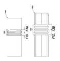
- FIG. 1Ais a view of a device delivery system
- FIG. 1Bis a cross-sectional view of the device delivery system along line 1 B- 1 B as shown in FIG. 1A ;
- FIG. 1Cis a representation of a cross-section of a vessel after rupturing of a sheath and expansion of a self-expanding medical device
- FIGS. 2A and 2Bare views of a portion of a device delivery system according to one embodiment of the present invention.
- FIGS. 3A and 3Bare views of a sheath assembly according to one embodiment of the present invention.
- FIGS. 4A and 4Bare views of the sheath assembly of FIG. 3A and the device delivery system of FIG. 2A according to one embodiment of the present invention
- FIGS. 5A , 5 B and 5 Crepresent the withdrawal of the device delivery system in one implementation of the present invention
- FIGS. 6A and 6Bare views of a portion of a device delivery system according to another embodiment of the present invention.
- FIG. 7is the device delivery system of FIG. 6A with the sheath assembly of FIG. 3A ;
- FIG. 8is a view of a portion of a device delivery system according to one embodiment of the present invention.
- FIG. 9is the device delivery system of FIG. 8 with the sheath assembly of FIG. 3A ;
- FIG. 10is a view of a portion of a device delivery system according to one embodiment of the present invention.
- FIG. 11is the device delivery system of FIG. 10 with the sheath assembly of FIG. 3A ;
- FIG. 12is an alternate embodiment of a catheter stop and a sheath ring
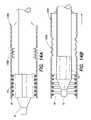
- FIGS. 13A and 13Billustrate a sheath according to an alternate embodiment of the present invention
- FIGS. 14A and 14Billustrate the sheath of FIGS. 13A and 13B mounted on a delivery system
- FIGS. 15A and 15Billustrate a sheath coupled to a catheter according to an alternate embodiment of the present invention.
- FIGS. 16A and 16Billustrate a delivery system according to an alternate embodiment of the present invention.
- the simultaneous motion of the ruptured sheath and the catheter upon being withdrawncan interfere with the proper placement of the delivered medical device, i.e., the stent.
- the present inventionserves to address the problem presented by this simultaneous motion of sheath and balloon by allowing the sheath to remain in position while the deflated balloon is being withdrawn. This mechanism decouples the two components of frictional force that can act on the deployed stent. The operation and configuration of embodiments of the present invention will be discussed in more detail below.
- a medical device delivery systemin general, includes a delivery catheter 12 with a balloon portion 14 positioned at, or enclosing, a distal end 11 of the catheter 12 .
- a lumenis provided to inflate the balloon 14 as necessary during the procedure to deliver a device 16 , for example, a stent, that is placed at the distal end of the catheter 12 and around the balloon 14 .
- the device 16is a self expanding device and, therefore, a cylindrical sheath 18 is also disposed at the distal end 11 of the catheter 12 so as to enclose the device 16 and the balloon 14 .
- the sheath 18is attached to the catheter 12 at some point proximal to the distal end 11 of the catheter 12 .
- FIG. 1BA cross-section of the system 10 , along line 1 B- 1 B, is presented in FIG. 1B . As shown, the sheath 18 surrounds the stent or device 16 and the balloon 14 positioned on the catheter 12 .
- the sheath 18may be made from a material having a grain, or fibers, that can be longitudinally oriented, for example, PTFE. Other materials may be used for the sheath as understood by one of ordinary skill in the art.
- the sheath 18upon expansion of the balloon 14 , will tear or rupture along a perforation or initial cut (not shown) in substantially a straight line following a longitudinal axis of the sheath 18 as defined, generally, by the catheter 12 . The expansion of the balloon 14 causes the sheath 18 to rupture. Once the sheath 18 ruptures, the stent 16 expands and is released into the vessel.
- the sheath 18is made from a plastic material and, as above, is generally cylindrical. Once the sheath 18 ruptures, however, it is no longer a cylinder and has a form that covers less than all of the circumference of the now-expanded stent 16 .
- FIG. 1Ca cross-section of the system 10 of FIG. 1A , the now-deflated balloon 14 is within the lumen of the expanded stent 16 . As shown, the ruptured sheath 18 is trapped between a portion of the now-expanded stent 16 and a vessel wall 20 .
- the ruptured sheath 18is only trapped between the stent 16 and the vessel wall 20 , for a portion, i.e., less than all, of the circumference of the now-expanded stent 16 .
- that portion of the ruptured sheath 18 trapped between the stent 16 and the vessel wall 20may pull on the deployed stent 16 and interfere with its proper placement.
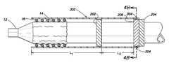
- a delivery system 200in accordance with one embodiment of the present invention, will now be described with reference to FIGS. 2A and 2B .
- the system 200includes a catheter 12 and balloon portion 14 as previously described.
- a distal catheter stop 202is positioned on the catheter 12 a predetermined distance from the distal end 11 of the catheter 12 .
- the distal catheter stop 202is a ring, for example, a radio-opaque (RO) platinum-iridium marker band as known to one of ordinary skill in the art.
- a gold RO marker band or heat-shrinkable tubingcan be used. The determination of the predetermined distance from the distal end of the catheter will be described in more detail below.
- the distal catheter stop 202is attached to the catheter 12 in any one of a number of ways. These mechanisms for attaching the distal catheter stop 202 to the catheter 12 include, but are not limited to, gluing, riveting, swaging or implementing the catheter stop as an integrated part of the catheter 12 .
- a proximal catheter stop 204is also attached to the catheter 12 at a location proximal to the location of the distal catheter stop 202 .
- the proximal catheter stop 204may also be implemented as a marker band or ring.
- the distance between the distal catheter stop 202 and the proximal catheter stop 204is a predetermined distance the details of which also will be discussed further below.
- a sheath ring 206is provided on the catheter at a location that is proximal to the distal catheter stop 202 .
- the sheath ring 206is not attached to the catheter 12 but is provided so as to slide along the outside of the catheter 12 .
- the sheath ring 206is positioned so as to slide along the catheter 12 between the distal catheter stop 202 and the proximal catheter stop 204 .
- FIG. 2BA cross-sectional view taken along the line 2 B- 2 B, as shown in FIG. 2A , is presented in FIG. 2B .
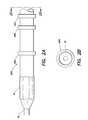
- a sheath assembly 300comprises a sheath 302 including a self-expanding stent 16 being held by the sheath 302 in its compressed state.
- the sheath 302 and stent 16may be made from materials that are known to one of ordinary skill in the art.
- the stent 16is positioned substantially at a distal and of the sheath 302 .
- the stent 16is a self-expanding device that is compressed and loaded into the sheath 302 .
- the sheath 302 loaded with the stent 16is loaded over the balloon portion 14 as opposed to crimping the stent 16 directly onto the balloon 14 .
- the stent 16is deployed by inflating the balloon portion 14 which splits the sheath 302 and in turn allows the stent 16 to self-expand.
- one or more openings or glue wicks 304are provided about the circumference of the sheath 302 and are located at the proximal end, i.e., the end of the sheath 302 at which the stent 16 is not located.
- the glue wicks 304are used to facilitate the connection of the sheath 302 to the sheath ring 206 as described below.
- a cross-sectional view taken along the line 3 B- 3 Bis provided in FIG. 3B .
- the sheath 302 with the stent 16 disposed within itis placed over the distal end 11 of the catheter 12 .
- the proximal end of the sheath 302is slid over the balloon portion 14 , past the distal catheter stop 202 , and oriented with the sheath ring 206 .
- the sheath 302has a length such that the stent 16 is oriented adjacent to the balloon portion 14 and the proximal end of the sheath 302 extends proximally past the distal catheter stop 202 .
- the characteristics of the sheath 302maintain the position of the stent 16 about the balloon portion 14 of the catheter 12 .
- the one or more glue wicks 304are aligned with the sheath ring 206 to facilitate the placement of glue that substantially permanently attaches the sheath 302 to the sheath ring 206 .
- gluethat substantially permanently attaches the sheath 302 to the sheath ring 206 .
- FIG. 4AA cross-section of the system shown in FIG. 4A along the line 4 B- 4 B is presented in FIG. 4B .
- a first distance L 1 from the distal end of the balloon portion 14 , at which the proximal edge of the distal catheter stop 202 is placed,is a function of the length of the balloon portion 14 and the length of the stent 16 .
- a second distance L 2represents the distance from the proximal edge of the distal catheter stop 202 to the distal edge of the sheath ring 206 as held in place by the sheath 302 .
- the second distance L 2is a function of at least one of the length of the balloon portion 14 and the stent 16 .
- the distance between the stops, and the location of the stops,is derived from the length of the stent and the length of the balloon portion.
- proximal catheter stop 204 adjacent the sheath ring 206prevents the sheath 302 from moving out of position while the catheter 12 is being distally advanced to the target site.
- the balloon portion 14is inflated sufficient to rupture the sheath 302 . Once the sheath 302 is ruptured, the stent 16 expands to contact the vessel wall 20 . The balloon portion 14 is then deflated to facilitate removal of the catheter 12 . As shown in FIG. 5A , the sheath 302 is now located between some portion of the expanded stent 16 and the vessel wall 20 .
- the sheath 302will remain in position between the expanded stent 16 and the vessel 20 .
- the catheterwill move proximally and the sheath ring 206 will slide along the catheter 12 , as shown in FIG. 5B .
- the distal catheter stop 202will engage with the sheath ring 206 .
- the sheath ring 206will no longer slide along the catheter but instead will be moved proximally by the distal catheter stop 202 . Movement of the sheath ring 206 will then pull the sheath 302 from between the expanded stent 16 and the vessel 20 , as shown in FIG. 5C .
- the balloon portion 14 of the catheter 12will start to be removed from within the expanded stent 16 prior to the start of the removal of the sheath 302 from between the expanded stent 16 and the vessel 20 .
- This operationoccurs while the catheter 12 is being continuously withdrawn and does not require having to stop the withdrawal.
- the balloon and sheathare withdrawn in two steps or stages. This two-stage operation reduces the total amount of friction that may be applied to the expanded stent 16 if the balloon portion 14 and the sheath 302 trapped between the stent 16 and the vessel 20 were to be withdrawn at the same time.
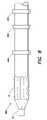
- a delivery system 600includes a catheter 12 having a balloon portion 14 .
- a plurality of distal stop blocks 602are attached about the circumference of the catheter 12 .
- a plurality of proximal stop blocks 604are provided about the circumference of the catheter 12 .
- the sheath ring 206is disposed to slide between the distal stop blocks 602 and the proximal stop blocks 604 .
- a cross-sectional view taken along the line 6 B- 6 Bis presented in FIG. 6B .
- the distal stop blocks 602 and the proximal stop blocks 604are shown as being symmetrically distributed about the circumference of the catheter 12 , i.e., approximately 90° from one another.
- these distal stop blocks 602also could be unequally spaced about the circumference.
- the sheath 302 with the stent 16is positioned about the distal portion of the catheter 12 and the sheath 302 is attached to the sheath ring 206 .
- the operation of the system as shown in FIG. 7is similar to that which has been described above.
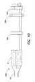
- a system 800includes the catheter 12 and the balloon portion 14 along with the distal catheter stop 202 and the proximal catheter stop 204 .
- a sheath cap ring 802is provided.
- the sheath cap ring 802is sized to fit into the proximal end of a sheath 302 as shown in FIG. 9 .
- a system 1000includes a catheter 12 and the balloon portion 14 along with the distal catheter stop 202 and the proximal catheter stop 204 .
- a sheath cap 1002is provided. The sheath cap 1002 is configured to receive the proximal end of a sheath 302 as shown in FIG. 11 .
- the marker bandsmay be unitary or integral rings.
- the ringsmay be implemented in two parts as shown in FIG. 12 .
- a first half-ring 400 and a second half-ring 402can be used to implement either of the stops 202 , 204 or the sheath ring 206 .
- one or the other of the half-rings 400 , 402may be used as one of the stops 202 , 204 .
- half-rings 400 , 402would have to be sized appropriately in order to contact the catheter 12 , if implemented as either of the stops 202 , 204 or to slide along the catheter 12 , if implemented as the sheath ring 206 . Further, one of ordinary skill in the art would also understand how the half-rings 400 , 402 could either be connected to one another or to the catheter 12 .
- a sheath 1300includes a bellows portion 1302 , as shown in FIGS. 13A and 13B .
- the bellows portion 1302is similar to a “bendy-straw” used by young children, and some adults.
- the bellows portion 1302has a compressed length LC and an expanded length LE.
- the sheath 1300is coupled, with the bellows portion 1302 in its compressed configuration, to a catheter 12 having a balloon portion 14 and a medical device 16 , for example, a self-expanding stent, such that the stent 16 is held in place by the sheath 1300 .
- the sheath 1300has a predetermined length and is attached to the catheter 12 at a position a predetermined distance, in the proximal direction, from the distal end of the catheter 12 , as shown in FIG. 14A .
- the balloon portion 14is deflated.
- the catheter 12is then withdrawn proximally from the location in the vessel where the stent 16 is to be positioned. Similar to that which has been described above, some portion of the ruptured sheath 1300 is trapped between the expanded stent 16 and the blood vessel (not shown for clarity.)
- the bellows portion 1302expands to its expanded length LE. Once the bellows portion 1302 has reached its expanded length, the sheath 1300 will begin moving out from between the stent 16 and the vessel.
- the expanded length LEis determined as a function of at least one of a length of the balloon portion 14 or the length of the medical device or stent 16 .
- the expanded length LEprovides this embodiment of the present invention with the ability to start removal of the balloon portion 14 from within the expanded device 16 prior to starting movement of the sheath 1300 from between the expanded stent 16 and the vessel.
- the sheath 1300in one embodiment, is glued directly to the outer surface of the catheter 12 .
- the sheath 1300may be attached to a sheath stop as described above.
- one of ordinary skill in the artwould understand that there are a number of different mechanisms for attaching or coupling the sheath 1300 to the catheter 12 .
- a catheter 12is provided with a balloon portion 14 about which a medical device or stent 16 is positioned. As shown in FIG. 15A , a sheath 18 is positioned about the device 16 and the balloon portion 14 so as to maintain the device 16 in its compressed state. A tether 1500 is wrapped around the catheter 12 and attaches a proximal portion of the sheath 18 to a tether anchor 1502 .
- FIG. 15Bafter the sheath 18 is ruptured due to expansion of the balloon portion 14 , similar to that which is described above, the catheter 12 is withdrawn. As above, some portion of the ruptured sheath 18 is trapped between the expanded device 16 and the vessel wall (not shown for clarity) and as the catheter 12 is withdrawn, the tether 1500 “spools out” allowing the deflated balloon portion 14 to move out proximally from within the expanded device 16 prior to movement of the sheath 18 . Once the tether 1500 reaches its predetermined limit, the sheath 1800 will begin its withdrawal from between the stent 16 and the vessel.
- the predetermined limit at which the tether 1500 stops spooling outis a function of one or more of a length of the stent 16 , the balloon portion 14 and the sheath 18 . Further, the location of the tether anchor 1502 is also chosen such that the balloon portion 14 moves a sufficient distance prior to the start of movement of the sheath 18 upon withdrawal.
- the tether 1500also serves to maintain the sheath 18 in position as the delivery system is being guided through the vessel anatomy to its destination.
- the compressed tether 1500serves to prevent the sheath from being pushed proximally off of the distal end of the delivery system.
- the tether 1500may be made from any one of a number of appropriate materials, for example, a biocompatible thread or suture, a biocompatible metal, or a shape-memory metal such as Nitinol.
- the tether 1500may be configured as a spring having a predetermined compressed length and a predetermined expanded length. The latter length would be chosen to represent the point at which the sheath would begin moving out from between the expanded stent 16 of the vessel wall as the catheter 12 is withdrawn.
- the tether 1500can be attached to the sheath 18 and the tether anchor 1502 by glue, mechanical fastener or any of a number of ways that are clear to one of ordinary skill in the art.
- a delivery system 1600includes a catheter 12 that is provided with a mechanism that allows the catheter 12 to rotate as it is withdrawn from the vessel.
- a catheter 12has a balloon portion 14 disposed at its distal end and a medical device 16 positioned about the balloon portion.
- a catheter rail 1602is provided on a portion of the catheter 12 proximal to the balloon portion 14 .
- a sheath 1604is positioned about the device 16 and balloon portion 14 .
- the sheath 1604includes a plurality of sheath guides 1606 disposed on an inner surface of the sheath 1604 .
- the sheath guides 1606are set apart from one another a longitudinal distance that is the same as a pitch of the catheter rail 1602 . This distance is chosen as a function of at least a length of the balloon portion 14 , a length of the stent 16 and a length of the sheath and 1604 .
- the catheter 12is withdrawn from the vessel, FIG. 16B .
- the catheter 12will turn as the sheath 1604 is held in place between the expanded stent 16 and the vessel wall (not shown for clarity.)
- the catheter rail 1602Once the catheter rail 1602 has reached its spiral end, it will contact one or more of the sheath guides 1606 and the sheath and 1604 will begin its withdrawal from between the expanded stent 16 and the vessel wall.
- the catheter rail 1602may be provided as a separate component, for example, a spring or spiral assembly, wrapped about the catheter 12 and attached with, for example, glue.
- the catheter rail 1602may be integral to the outer portion of the catheter 12 , i.e., implemented as a polymer overmold thereon.
- the sheath guide 1606in one embodiment, is implemented as a spring or spiral situated inside the sheath 1604 .
- the springcould be glued to the inside of the sheath.
- the sheath guides 1606in another embodiment, may be implemented as indentations created on the inside of the sheath 1604 by a molding operation applied to the outside of the sheath 1604 .
Landscapes
- Health & Medical Sciences (AREA)
- Engineering & Computer Science (AREA)
- Biomedical Technology (AREA)
- Cardiology (AREA)
- Oral & Maxillofacial Surgery (AREA)
- Transplantation (AREA)
- Heart & Thoracic Surgery (AREA)
- Vascular Medicine (AREA)
- Life Sciences & Earth Sciences (AREA)
- Animal Behavior & Ethology (AREA)
- General Health & Medical Sciences (AREA)
- Public Health (AREA)
- Veterinary Medicine (AREA)
- Media Introduction/Drainage Providing Device (AREA)
Abstract
Description
Claims (13)
Priority Applications (5)
| Application Number | Priority Date | Filing Date | Title |
|---|---|---|---|
| US11/832,002US8252035B2 (en) | 2007-08-01 | 2007-08-01 | Device delivery system with two stage withdrawal |
| EP08836640AEP2190387A1 (en) | 2007-08-01 | 2008-08-01 | Device delivery system with two stage withdrawal |
| CN2008801022284ACN103281991A (en) | 2007-08-01 | 2008-08-01 | Device delivery system with two stage withdrawal |
| JP2010519242AJP2010535066A (en) | 2007-08-01 | 2008-08-01 | 2-stage device delivery system |
| PCT/US2008/071937WO2009045623A1 (en) | 2007-08-01 | 2008-08-01 | Device delivery system with two stage withdrawal |
Applications Claiming Priority (1)
| Application Number | Priority Date | Filing Date | Title |
|---|---|---|---|
| US11/832,002US8252035B2 (en) | 2007-08-01 | 2007-08-01 | Device delivery system with two stage withdrawal |
Publications (2)
| Publication Number | Publication Date |
|---|---|
| US20090036966A1 US20090036966A1 (en) | 2009-02-05 |
| US8252035B2true US8252035B2 (en) | 2012-08-28 |
Family
ID=39865314
Family Applications (1)
| Application Number | Title | Priority Date | Filing Date |
|---|---|---|---|
| US11/832,002Expired - Fee RelatedUS8252035B2 (en) | 2007-08-01 | 2007-08-01 | Device delivery system with two stage withdrawal |
Country Status (5)
| Country | Link |
|---|---|
| US (1) | US8252035B2 (en) |
| EP (1) | EP2190387A1 (en) |
| JP (1) | JP2010535066A (en) |
| CN (1) | CN103281991A (en) |
| WO (1) | WO2009045623A1 (en) |
Cited By (2)
| Publication number | Priority date | Publication date | Assignee | Title |
|---|---|---|---|---|
| US20100145429A1 (en)* | 2008-12-09 | 2010-06-10 | Cook Incorporated | Introducer sheath and method of manufacture |
| US10383752B2 (en) | 2015-01-11 | 2019-08-20 | Ascyrus Medical, Llc | Hybrid device for surgical aortic repair configured for adaptability of organs of various anatomical characteristics and method of using the same |
Families Citing this family (32)
| Publication number | Priority date | Publication date | Assignee | Title |
|---|---|---|---|---|
| DE102008040252A1 (en)* | 2008-07-08 | 2010-01-14 | Biotronik Vi Patent Ag | Delivery system for a medical device with a sleeve and cover for a delivery system for a medical device |
| US9149376B2 (en) | 2008-10-06 | 2015-10-06 | Cordis Corporation | Reconstrainable stent delivery system |
| US20120310321A1 (en)* | 2009-10-05 | 2012-12-06 | Bradley Beach | Reconstrainable stent delivery system |
| TWI516244B (en) | 2009-04-20 | 2016-01-11 | 大塚醫療器材股份有限公司 | Delivery assembly for occlusion device using mechanical interlocking coupling mechanism |
| US8870950B2 (en) | 2009-12-08 | 2014-10-28 | Mitral Tech Ltd. | Rotation-based anchoring of an implant |
| US20110224785A1 (en) | 2010-03-10 | 2011-09-15 | Hacohen Gil | Prosthetic mitral valve with tissue anchors |
| US11653910B2 (en) | 2010-07-21 | 2023-05-23 | Cardiovalve Ltd. | Helical anchor implantation |
| US9763657B2 (en) | 2010-07-21 | 2017-09-19 | Mitraltech Ltd. | Techniques for percutaneous mitral valve replacement and sealing |
| WO2013021374A2 (en) | 2011-08-05 | 2013-02-14 | Mitraltech Ltd. | Techniques for percutaneous mitral valve replacement and sealing |
| EP2739214B1 (en) | 2011-08-05 | 2018-10-10 | Cardiovalve Ltd | Percutaneous mitral valve replacement and sealing |
| US8852272B2 (en) | 2011-08-05 | 2014-10-07 | Mitraltech Ltd. | Techniques for percutaneous mitral valve replacement and sealing |
| US9039752B2 (en)* | 2011-09-20 | 2015-05-26 | Aga Medical Corporation | Device and method for delivering a vascular device |
| US8621975B2 (en) | 2011-09-20 | 2014-01-07 | Aga Medical Corporation | Device and method for treating vascular abnormalities |
| US20150351906A1 (en) | 2013-01-24 | 2015-12-10 | Mitraltech Ltd. | Ventricularly-anchored prosthetic valves |
| JP5960910B2 (en)* | 2013-04-01 | 2016-08-02 | テルモ株式会社 | In-vivo indwelling delivery system |
| EP3043755B1 (en)* | 2013-09-12 | 2022-10-19 | St. Jude Medical, Cardiology Division, Inc. | Atraumatic interface in an implant delivery device |
| CN103830027A (en)* | 2014-03-21 | 2014-06-04 | 董绍安 | Accurate positioning human body lumen support placing device |
| EP3174502B1 (en) | 2014-07-30 | 2022-04-06 | Cardiovalve Ltd | Apparatus for implantation of an articulatable prosthetic valve |
| CN110141399B (en) | 2015-02-05 | 2021-07-27 | 卡迪尔维尔福股份有限公司 | Prosthetic valve with axial sliding frame |
| US10531866B2 (en) | 2016-02-16 | 2020-01-14 | Cardiovalve Ltd. | Techniques for providing a replacement valve and transseptal communication |
| CN106214205A (en)* | 2016-07-26 | 2016-12-14 | 加奇生物科技(上海)有限公司苏州分公司 | Arteries induction system |
| US20190231525A1 (en) | 2016-08-01 | 2019-08-01 | Mitraltech Ltd. | Minimally-invasive delivery systems |
| CA3031187A1 (en) | 2016-08-10 | 2018-02-15 | Cardiovalve Ltd. | Prosthetic valve with concentric frames |
| US10537426B2 (en) | 2017-08-03 | 2020-01-21 | Cardiovalve Ltd. | Prosthetic heart valve |
| US10888421B2 (en) | 2017-09-19 | 2021-01-12 | Cardiovalve Ltd. | Prosthetic heart valve with pouch |
| US10575948B2 (en) | 2017-08-03 | 2020-03-03 | Cardiovalve Ltd. | Prosthetic heart valve |
| US12064347B2 (en) | 2017-08-03 | 2024-08-20 | Cardiovalve Ltd. | Prosthetic heart valve |
| US11793633B2 (en) | 2017-08-03 | 2023-10-24 | Cardiovalve Ltd. | Prosthetic heart valve |
| US11246704B2 (en) | 2017-08-03 | 2022-02-15 | Cardiovalve Ltd. | Prosthetic heart valve |
| GB201720803D0 (en) | 2017-12-13 | 2018-01-24 | Mitraltech Ltd | Prosthetic Valve and delivery tool therefor |
| GB201800399D0 (en) | 2018-01-10 | 2018-02-21 | Mitraltech Ltd | Temperature-control during crimping of an implant |
| US12357459B2 (en) | 2020-12-03 | 2025-07-15 | Cardiovalve Ltd. | Transluminal delivery system |
Citations (23)
| Publication number | Priority date | Publication date | Assignee | Title |
|---|---|---|---|---|
| US5549635A (en)* | 1994-01-24 | 1996-08-27 | Solar, Rita & Gaterud, Ltd. | Non-deformable self-expanding parallel flow endovascular stent and deployment apparatus therefore |
| US5702418A (en)* | 1995-09-12 | 1997-12-30 | Boston Scientific Corporation | Stent delivery system |
| US5868779A (en)* | 1997-08-15 | 1999-02-09 | Ruiz; Carlos E. | Apparatus and methods for dilating vessels and hollow-body organs |
| US6019778A (en)* | 1998-03-13 | 2000-02-01 | Cordis Corporation | Delivery apparatus for a self-expanding stent |
| US6113608A (en)* | 1998-11-20 | 2000-09-05 | Scimed Life Systems, Inc. | Stent delivery device |
| US6129755A (en)* | 1998-01-09 | 2000-10-10 | Nitinol Development Corporation | Intravascular stent having an improved strut configuration |
| US6273895B1 (en)* | 1995-06-06 | 2001-08-14 | Corvita Corporation | Method of measuring a body cavity |
| WO2001097715A1 (en) | 2000-06-22 | 2001-12-27 | Jan Otto Solem | Delivery system |
| US6432130B1 (en)* | 2000-04-20 | 2002-08-13 | Scimed Life Systems, Inc. | Fully sheathed balloon expandable stent delivery system |
| US6443971B1 (en)* | 1999-12-21 | 2002-09-03 | Advanced Cardiovascular Systems, Inc. | System for, and method of, blocking the passage of emboli through a vessel |
| US6520983B1 (en)* | 1998-03-31 | 2003-02-18 | Scimed Life Systems, Inc. | Stent delivery system |
| WO2003039345A2 (en) | 2001-11-09 | 2003-05-15 | Rubicon Medical, Inc. | Stent delivery device with embolic protection |
| US6629992B2 (en)* | 2000-08-04 | 2003-10-07 | Advanced Cardiovascular Systems, Inc. | Sheath for self-expanding stent |
| US20030199963A1 (en)* | 2002-04-23 | 2003-10-23 | Numed, Inc. | System for implanting a replacement valve |
| US20040148000A1 (en)* | 2003-01-24 | 2004-07-29 | Bilge Fertac H. | Self expanding stent delivery system with balloon |
| US6790224B2 (en)* | 2002-02-04 | 2004-09-14 | Scimed Life Systems, Inc. | Medical devices |
| US20050027305A1 (en)* | 2002-04-23 | 2005-02-03 | Brian Shiu | Integrated mechanical handle with quick slide mechanism |
| US6859986B2 (en)* | 2003-02-20 | 2005-03-01 | Cordis Corporation | Method system for loading a self-expanding stent |
| US6911039B2 (en)* | 2002-04-23 | 2005-06-28 | Medtronic Vascular, Inc. | Integrated mechanical handle with quick slide mechanism |
| US20060015171A1 (en)* | 2004-07-16 | 2006-01-19 | Armstrong Joseph R | Deployment system for intraluminal devices |
| US20080140051A1 (en)* | 2006-12-06 | 2008-06-12 | Guidant Endovascular Solutions | Highly trackable balloon catheter system and method for collapsing an expanded medical device |
| US20090048480A1 (en)* | 2007-08-13 | 2009-02-19 | Paracor Medical, Inc. | Cardiac harness delivery device |
| US7635382B2 (en)* | 2003-10-22 | 2009-12-22 | Medtronic Vascular, Inc. | Delivery system for long self-expanding stents |
Family Cites Families (11)
| Publication number | Priority date | Publication date | Assignee | Title |
|---|---|---|---|---|
| US6113576A (en)* | 1993-08-04 | 2000-09-05 | Lake Region Manufacturing, Inc. | Thrombolysis catheter system with fixed length infusion zone |
| US5534007A (en)* | 1995-05-18 | 1996-07-09 | Scimed Life Systems, Inc. | Stent deployment catheter with collapsible sheath |
| US6280414B1 (en)* | 1998-09-30 | 2001-08-28 | Medtronic Ave, Inc. | Method and apparatus for local delivery of therapeutic agent |
| FR2788216B1 (en)* | 1999-01-08 | 2001-03-30 | Balt Extrusion | DEVICE FOR SEALING AN ANEVRISM OR THE LIKE IN A BLOOD VESSEL LIKE AN ARTERY |
| US6423052B1 (en)* | 2000-08-18 | 2002-07-23 | Endovascular Technologies, Inc. | Torque absorbing catheter |
| US6890340B2 (en)* | 2001-11-29 | 2005-05-10 | Medtronic Vascular, Inc. | Apparatus for temporary intraluminal protection |
| US8221387B2 (en)* | 2004-02-24 | 2012-07-17 | Boston Scientific Scimed, Inc. | Catheter having an improved distal tip |
| US7306623B2 (en)* | 2005-01-13 | 2007-12-11 | Medtronic Vascular, Inc. | Branch vessel graft design and deployment method |
| CN101257943B (en)* | 2005-07-05 | 2013-10-09 | 安乔斯里德公司 | balloon catheter |
| CN2838541Y (en)* | 2005-11-08 | 2006-11-22 | 陈鹏宏 | Nickel-titanium prostate stent implanter |
| JP2012110562A (en)* | 2010-11-26 | 2012-06-14 | Goodman Co Ltd | Catheter manufacturing method |
- 2007
- 2007-08-01USUS11/832,002patent/US8252035B2/ennot_activeExpired - Fee Related
- 2008
- 2008-08-01JPJP2010519242Apatent/JP2010535066A/enactivePending
- 2008-08-01EPEP08836640Apatent/EP2190387A1/ennot_activeWithdrawn
- 2008-08-01CNCN2008801022284Apatent/CN103281991A/enactivePending
- 2008-08-01WOPCT/US2008/071937patent/WO2009045623A1/enactiveApplication Filing
Patent Citations (25)
| Publication number | Priority date | Publication date | Assignee | Title |
|---|---|---|---|---|
| US5549635A (en)* | 1994-01-24 | 1996-08-27 | Solar, Rita & Gaterud, Ltd. | Non-deformable self-expanding parallel flow endovascular stent and deployment apparatus therefore |
| US6273895B1 (en)* | 1995-06-06 | 2001-08-14 | Corvita Corporation | Method of measuring a body cavity |
| US5702418A (en)* | 1995-09-12 | 1997-12-30 | Boston Scientific Corporation | Stent delivery system |
| US5868779A (en)* | 1997-08-15 | 1999-02-09 | Ruiz; Carlos E. | Apparatus and methods for dilating vessels and hollow-body organs |
| US6129755A (en)* | 1998-01-09 | 2000-10-10 | Nitinol Development Corporation | Intravascular stent having an improved strut configuration |
| US6019778A (en)* | 1998-03-13 | 2000-02-01 | Cordis Corporation | Delivery apparatus for a self-expanding stent |
| US6520983B1 (en)* | 1998-03-31 | 2003-02-18 | Scimed Life Systems, Inc. | Stent delivery system |
| US6113608A (en)* | 1998-11-20 | 2000-09-05 | Scimed Life Systems, Inc. | Stent delivery device |
| US6443971B1 (en)* | 1999-12-21 | 2002-09-03 | Advanced Cardiovascular Systems, Inc. | System for, and method of, blocking the passage of emboli through a vessel |
| US6432130B1 (en)* | 2000-04-20 | 2002-08-13 | Scimed Life Systems, Inc. | Fully sheathed balloon expandable stent delivery system |
| WO2001097715A1 (en) | 2000-06-22 | 2001-12-27 | Jan Otto Solem | Delivery system |
| US6656213B2 (en) | 2000-06-22 | 2003-12-02 | Jan Otto Solem | Stent delivery system |
| US6629992B2 (en)* | 2000-08-04 | 2003-10-07 | Advanced Cardiovascular Systems, Inc. | Sheath for self-expanding stent |
| WO2003039345A2 (en) | 2001-11-09 | 2003-05-15 | Rubicon Medical, Inc. | Stent delivery device with embolic protection |
| US6790224B2 (en)* | 2002-02-04 | 2004-09-14 | Scimed Life Systems, Inc. | Medical devices |
| US20030199963A1 (en)* | 2002-04-23 | 2003-10-23 | Numed, Inc. | System for implanting a replacement valve |
| US20050027305A1 (en)* | 2002-04-23 | 2005-02-03 | Brian Shiu | Integrated mechanical handle with quick slide mechanism |
| US6911039B2 (en)* | 2002-04-23 | 2005-06-28 | Medtronic Vascular, Inc. | Integrated mechanical handle with quick slide mechanism |
| US7419501B2 (en)* | 2002-04-23 | 2008-09-02 | Medtronic Vascular, Inc. | Integrated mechanical handle with quick slide mechanism |
| US20040148000A1 (en)* | 2003-01-24 | 2004-07-29 | Bilge Fertac H. | Self expanding stent delivery system with balloon |
| US6859986B2 (en)* | 2003-02-20 | 2005-03-01 | Cordis Corporation | Method system for loading a self-expanding stent |
| US7635382B2 (en)* | 2003-10-22 | 2009-12-22 | Medtronic Vascular, Inc. | Delivery system for long self-expanding stents |
| US20060015171A1 (en)* | 2004-07-16 | 2006-01-19 | Armstrong Joseph R | Deployment system for intraluminal devices |
| US20080140051A1 (en)* | 2006-12-06 | 2008-06-12 | Guidant Endovascular Solutions | Highly trackable balloon catheter system and method for collapsing an expanded medical device |
| US20090048480A1 (en)* | 2007-08-13 | 2009-02-19 | Paracor Medical, Inc. | Cardiac harness delivery device |
Non-Patent Citations (1)
| Title |
|---|
| International Search Report for PCT Application No. PCT/US2008/071937, dated Jan. 29, 2009. |
Cited By (2)
| Publication number | Priority date | Publication date | Assignee | Title |
|---|---|---|---|---|
| US20100145429A1 (en)* | 2008-12-09 | 2010-06-10 | Cook Incorporated | Introducer sheath and method of manufacture |
| US10383752B2 (en) | 2015-01-11 | 2019-08-20 | Ascyrus Medical, Llc | Hybrid device for surgical aortic repair configured for adaptability of organs of various anatomical characteristics and method of using the same |
Also Published As
| Publication number | Publication date |
|---|---|
| CN103281991A (en) | 2013-09-04 |
| EP2190387A1 (en) | 2010-06-02 |
| JP2010535066A (en) | 2010-11-18 |
| US20090036966A1 (en) | 2009-02-05 |
| WO2009045623A1 (en) | 2009-04-09 |
Similar Documents
| Publication | Publication Date | Title |
|---|---|---|
| US8252035B2 (en) | Device delivery system with two stage withdrawal | |
| US11129738B2 (en) | Self-expanding device delivery apparatus with dual function bump | |
| US7959661B2 (en) | Delivery system for endoluminal implant | |
| US8545544B2 (en) | Delivery catheter with constraining sheath and methods of deploying medical devices into a body lumen | |
| CA2701576C (en) | Delivery system for a self-expanding device for placement in a bodily lumen | |
| US20150246210A1 (en) | Delivery system and method of use for deployment of self-expandable vascular device | |
| EP0943300A1 (en) | Reversible action endoprosthesis delivery device. | |
| US10932932B2 (en) | Delivery device with an expandable positioner for positioning a prosthesis | |
| JP2005533557A (en) | Intraluminal dilation system | |
| WO2010008571A1 (en) | Introducer for endovascular implants | |
| EP3607916A1 (en) | Stent delivery with expansion assisting delivery wire | |
| EP2552361B1 (en) | Systems for delivering a stent to a body lumen |
Legal Events
| Date | Code | Title | Description |
|---|---|---|---|
| AS | Assignment | Owner name:CAPPELLA, INC., MASSACHUSETTS Free format text:ASSIGNMENT OF ASSIGNORS INTEREST;ASSIGNORS:O'CONNOR, THERESE;GILMORE, MICHAEL;SLATTERY, DAVID;AND OTHERS;REEL/FRAME:019663/0781 Effective date:20070801 | |
| AS | Assignment | Owner name:NOBLE VENTURE FINANCE II S.A., LUXEMBOURG Free format text:SECURITY AGREEMENT;ASSIGNOR:CAPPELLA, INC.;REEL/FRAME:020115/0274 Effective date:20071101 | |
| AS | Assignment | Owner name:CAPPELLA MEDICAL DEVICES LIMITED, IRELAND Free format text:TERMINATION OF INTELLECTUAL PROPERTY SECURITY AGREEMENT (PATENTS & TRADEMARKS);ASSIGNOR:NOBLE VENTURE FINANCE II S.A.;REEL/FRAME:025090/0597 Effective date:20101001 Owner name:CAPPELLA, INC., MASSACHUSETTS Free format text:TERMINATION OF INTELLECTUAL PROPERTY SECURITY AGREEMENT (PATENTS & TRADEMARKS);ASSIGNOR:NOBLE VENTURE FINANCE II S.A.;REEL/FRAME:025090/0597 Effective date:20101001 | |
| AS | Assignment | Owner name:SILICON VALLEY BANK, AS A LENDER, MASSACHUSETTS Free format text:SECURITY AGREEMENT;ASSIGNOR:CAPPELLA, INC.;REEL/FRAME:025411/0365 Effective date:20101026 Owner name:KREOS CAPITAL III (UK) LIMITED, AS A LENDER AND AG Free format text:SECURITY AGREEMENT;ASSIGNOR:CAPPELLA, INC.;REEL/FRAME:025411/0365 Effective date:20101026 | |
| ZAAA | Notice of allowance and fees due | Free format text:ORIGINAL CODE: NOA | |
| ZAAB | Notice of allowance mailed | Free format text:ORIGINAL CODE: MN/=. | |
| STCF | Information on status: patent grant | Free format text:PATENTED CASE | |
| AS | Assignment | Owner name:CAPPELLA PEEL AWAY INC., DELAWARE Free format text:LICENSE;ASSIGNOR:CAPPELLA, INC.;REEL/FRAME:032887/0941 Effective date:20140502 | |
| AS | Assignment | Owner name:CAPPELLA PEEL AWAY INC., DELAWARE Free format text:LICENSE;ASSIGNOR:CAPPELLA, INC.;REEL/FRAME:033166/0930 Effective date:20140603 | |
| AS | Assignment | Owner name:CAPPELLA, INC., DELAWARE Free format text:PARTIAL RELEASE;ASSIGNORS:KREOS CAPITAL III (UK) LIMITED;SILICON VALLEY BANK;REEL/FRAME:033332/0104 Effective date:20140625 | |
| FPAY | Fee payment | Year of fee payment:4 | |
| AS | Assignment | Owner name:PIERRE HOCHULI, UNITED KINGDOM Free format text:SECURITY INTEREST;ASSIGNOR:CAPPELLA INC.;REEL/FRAME:043069/0894 Effective date:20170721 Owner name:ACT VENTURE CAPITAL LIMITED, IRELAND Free format text:SECURITY INTEREST;ASSIGNOR:CAPPELLA INC.;REEL/FRAME:043069/0894 Effective date:20170721 | |
| AS | Assignment | Owner name:MERIT MEDICAL IRELAND LIMITED INCORPORATED, IRELAN Free format text:ASSIGNMENT OF ASSIGNORS INTEREST;ASSIGNOR:CAPPELLA, INC.;REEL/FRAME:046597/0185 Effective date:20180801 | |
| AS | Assignment | Owner name:MERIT MEDICAL IRELAND LIMITED, IRELAND Free format text:CORRECTIVE ASSIGNMENT TO CORRECT THE ASSIGNEE NAME PREVIOUSLY RECORDED AT REEL: 046597 FRAME: 0185. ASSIGNOR(S) HEREBY CONFIRMS THE ASSIGNMENT;ASSIGNOR:CAPPELLA, INC.;REEL/FRAME:047044/0988 Effective date:20180801 | |
| MAFP | Maintenance fee payment | Free format text:PAYMENT OF MAINTENANCE FEE, 8TH YR, SMALL ENTITY (ORIGINAL EVENT CODE: M2552); ENTITY STATUS OF PATENT OWNER: SMALL ENTITY Year of fee payment:8 | |
| FEPP | Fee payment procedure | Free format text:MAINTENANCE FEE REMINDER MAILED (ORIGINAL EVENT CODE: REM.); ENTITY STATUS OF PATENT OWNER: SMALL ENTITY | |
| LAPS | Lapse for failure to pay maintenance fees | Free format text:PATENT EXPIRED FOR FAILURE TO PAY MAINTENANCE FEES (ORIGINAL EVENT CODE: EXP.); ENTITY STATUS OF PATENT OWNER: SMALL ENTITY | |
| STCH | Information on status: patent discontinuation | Free format text:PATENT EXPIRED DUE TO NONPAYMENT OF MAINTENANCE FEES UNDER 37 CFR 1.362 | |
| FP | Lapsed due to failure to pay maintenance fee | Effective date:20240828 |