US8252022B2 - Metal vascular aperture closure device - Google Patents
Metal vascular aperture closure deviceDownload PDFInfo
- Publication number
- US8252022B2 US8252022B2US12/502,034US50203409AUS8252022B2US 8252022 B2US8252022 B2US 8252022B2US 50203409 AUS50203409 AUS 50203409AUS 8252022 B2US8252022 B2US 8252022B2
- Authority
- US
- United States
- Prior art keywords
- closure device
- blood vessel
- petals
- metal
- example embodiment
- Prior art date
- Legal status (The legal status is an assumption and is not a legal conclusion. Google has not performed a legal analysis and makes no representation as to the accuracy of the status listed.)
- Active, expires
Links
- GDOPTJXRTPNYNR-UHFFFAOYSA-NCC1CCCC1Chemical compoundCC1CCCC1GDOPTJXRTPNYNR-UHFFFAOYSA-N0.000description1
- IFTRQJLVEBNKJK-UHFFFAOYSA-NCCC1CCCC1Chemical compoundCCC1CCCC1IFTRQJLVEBNKJK-UHFFFAOYSA-N0.000description1
Images


Classifications
- A—HUMAN NECESSITIES
- A61—MEDICAL OR VETERINARY SCIENCE; HYGIENE
- A61B—DIAGNOSIS; SURGERY; IDENTIFICATION
- A61B17/00—Surgical instruments, devices or methods
- A61B17/0057—Implements for plugging an opening in the wall of a hollow or tubular organ, e.g. for sealing a vessel puncture or closing a cardiac septal defect
- A61B2017/00646—Type of implements
- A61B2017/00659—Type of implements located only on one side of the opening
Definitions
- the inventionrelates generally to the closure of punctures blood vessel walls during catheter based intravascular surgical procedures. More specifically, the invention relates to sutureless closure of wounds created in blood vessel walls in intravascular surgery and joining the wound edges without stitching the edges together.
- a puncture as discussedshould be considered to include an incision, slit or circular opening that passes through the wall of a blood vessel.
- the terms blood vessel wall aperture, wound aperture, puncture and incisionare not to be considered to be limited to any particular shape of opening.
- a blood vessel wall aperture, puncture or incisionincludes any opening made in a blood vessel wall or the wall of another bodily organ. This may include but is not limited to surgical incisions, punctures made by needles and openings created with a trephine.
- an apertureis left in the wall of the artery or vein that has been accessed.
- These aperturestend to bleed, particularly in the case of arterial punctures because of the higher arterial blood pressure as compared to the venous blood pressure.
- an elastic pressure bandageis typically applied over the site of the puncture to exert pressure on the site in an attempt to prevent the blood clot from being dislodged by blood flow within the blood vessel. With this scenario, it is often necessary for the pressure bandage to remain in place from 8 to 24 hours. Often, the use of a pressure bandage prevents ambulation of the patient and requires that the patient remain resting in bed.
- suture deviceswhich do not provide a complete closure or seal of the puncture wound
- staple based devicessuch as the Starclose device
- Other deviceshave utilized balloons or toggle bolt like structures in an effort to close the puncture wound left behind after intravascular procedures.
- the absorbable metal closure device of the present inventionsolves many of the problems and makes improvements over the prior art.
- the absorbable metal closure device of the inventiongenerally includes an internal member, an external member and a filament.
- the internal memberis adapted to be inserted percutaneously through a puncture wound in a blood vessel wall into the lumen of the blood vessel.
- the internal membergenerally includes two or more petals. In one example embodiment, there are three petals.
- the petalsare flat members formed of magnesium and each of the petals is centrally pierced by at least two apertures. In an example embodiment including two petals, the apertures are oriented to be aligned approximately 90° from each other relative to the short axis of the petals.
- Other featuresmay be used to urge the petals into desired alignment upon deployment into the blood vessel lumen.
- the featuresmay include a single aperture in each petal or ridges that urge the petals into the desired alignment.
- at least some of the petalscan be permitted to rotate freely relative to other petals to take random angular orientations relative to the other petals.
- the aperturesare aligned in one petal at approximately thirty degrees relative to the short axis and another petal at approximately ninety degrees relative to short axis and a third petal at approximately one hundred fifty degrees to the short axis.
- the aperturesare aligned in one petal at approximately zero degrees relative to the short axis and another petal at approximately 60° relative to short axis and a third petal at approximately 120° to the short axis.
- the aperturesare aligned relative to the petals so that when the apertures are brought into alignment by passing another structure through them, such as a filament, the petals are drawn into a particular alignment relative to each other which is expanded relative to the width of any individual petal.
- the two metal petalscover a surface area greater than either of the metal petals alone.
- the three petalsare adapted to be aligned generally parallel to one another prior to insertion and are dimensioned so as to be passable through the aperture when aligned.
- one of the petalshas one or two small apertures centrally locate therein and a second and further petals located proximal to the first petal have a single larger aperture centrally located.
- the second and further petalsrotate freely relative to the first petal and settle into random angular orientations relative to the first petal when freed from the confines of a delivery device into a blood vessel lumen.
- one or more of the petalspresents a recess or pocket into which a buffer, as described elsewhere in this application, may be inserted.
- the pocketmay be located centrally in the petal so as to be hidden or covered by the overlap of other adjacent petals.
- An example external membergenerally includes a stem portion, an expandable retainer portion and a locking part.
- the stemin one example embodiment, is a generally cylindrical structure that has a length and diameter that allows it to fit within the blood vessel wall aperture.
- the stemalso defines passages therethrough sized to receive the filament therethrough.
- the stemis arranged so that its internal face abuts the petals when the petals are drawn against it by the filament.
- the stemalso has an external face adapted to abut the expandable retainer portion when the filament is tensioned.
- the external face of the stemis permanently secured to the expandable retainer portion.
- the expandable retainer portiongenerally includes a distal portion, a proximal portion and an expansion portion.
- the distal portion in one example embodimentmay be generally cylindrical and adapted to abut the external face of the stem.
- the proximal portionmay also be substantially cylindrical in shape.
- the expansion portionis structured so that it can be expanded by deformation of the metal so as to be shiftable from an unexpanded configuration to an expanded configuration.
- the expansionis accomplished by tensioning the filament to compress the proximal portion toward the distal portion.
- the diameter of the expandable retainer, when unexpandedis about equal to the petal width and to the spacer diameter.
- the expandable retainermay have a greatest extent equal to approximately 3 to 4 times the spacer diameter. As such, the expanded extent is also approximately 3 to 4 times the greatest dimension of the puncture wound in the blood vessel wall.
- the locking partin an example embodiment, includes a cam or wedge that immovably secures the filament after it has been placed under tension so that it will remain under tension and not be released.
- the locking partmay include a disc having three apertures in it about which the filament may be passed in order to create a knot to secure the filament to the locking part.
- the locking partmay include a wedge or cam which can be pressed into a receiver so as to entrap the filament between the wedge and the receiver and secure it by friction and compression.
- the locking partincludes deformable parts that can be deformed to collapse inwardly to entrap the filament between the deformable parts and thus grip the filament to secure it against longitudinal movement.
- the external membermay include a metal coiled member.
- the coiled memberis stretched longitudinally along a linear member.
- the coiled memberis expanded by compressing it longitudinally while expanding it into disc like configuration transversely.
- the transverse extent of the disc like configurationcan be varied by twisting the coiled member relative to the linear member. A tighter twist leads to a lesser transverse extent or diameter while a looser twist leads to a greater transverse extent or diameter.
- the disc like coiled membercan be placed near or against the exterior of the blood vessel wall and expanded to substantially secure its position relative to the blood vessel wall
- the external membermay include a deformable structure that can be deformed from a generally linear configuration to an expanded orientation wherein the deformable structure assumes, for example a bowtie orientation.
- the deformable structurehas several apertures therein through which the filament passes and several twisted portions and/or portions having a reduced cross sectional area that facilitate folding of the deformable structure.
- the external membermay include a metal deformable member that includes fingers or claws that can be actuated to deform inwardly and grip tissue near the blood vessel wall or grip the blood vessel wall itself.
- This embodimentmay include a sliding external sleeve that can be advanced at least partially over the fingers or claws to urge them inwardly to facilitate the tissue gripping action.
- the inward deformationmay also lead to gripping of the filament within the external member structure to secure the movement of the filament relative to the external member and to secure the external member relative to the internal member via the intervening filament.
- the filamentmay, for example, be formed from an absorbable suture material.
- the filamentin an example embodiment, is looped so that each of its free ends passes through the apertures in each of the petals, through the stem, through the expandable retainer, through the locking part and extends beyond the absorbable metal closure device having sufficient length to be passed well outside the tissue tract leading from the blood vessel wall puncture to the skin and outside of the body when the closure device is inserted into a puncture wound in a blood vessel.
- the biodegradable metal closure devicein an example embodiment, is formed of an alkaline earth metal, such as magnesium (atomic number 12) or a rare earth element such as dysprosium (atomic number 66.)
- the absorbable metal closure deviceis formed of magnesium that has been refined to be 99.8% pure magnesium.
- the 0.20%includes normally present impurities in the metal.
- the absorbable metal closure deviceis formed of magnesium that is between 90.00% and 99.99% pure.
- magnesiumpossesses anti-inflammatory properties as well as properties that promote endothelial cell adherence which are expected to facilitate biological repair of an aperture in which the metal closure device is located in an implanted environment.
- the absorbable metal closure device of the inventioncan be passed through an introducer sheath that is already in a tissue tract from the puncture and medical procedure.
- the absorbable metal closure devicecan be arranged so that the filament is slack and the petals are aligned to be generally parallel with their long axes aligned generally parallel with the long axis of the introducer sheath.
- the petalsare followed in the introducer sheath by the stem and then the retainer in an unexpanded state.
- the filamentsthen trail behind the retainer up through the length of the introducer to a location outside of the body.
- the absorbable metal closure devicecan be pushed through the sheath by the use of a deployment tube formed of, for example, a polymer material such as Poly[aryl ether ether ketone] (PEEK.)
- the filamentmay be routed through the lumen of the deployment tube. After the absorbable metal closure device has been advanced through the delivery tube by pushing it with the deployment tube and at least partially into the lumen of the blood vessel through the puncture wound, the filament may be tensioned to cause the petals to align based on the orientation of the apertures through the petals through which the filament passes. In an example embodiment having three petals, this would cause the three petals to be aligned so that their long axes are at 0, 60 and 120 degrees relative to one another. In another example embodiment, the filament has a resiliency such that when the petals are free of the delivery tube in the blood stream the resiliency of the filament tends to urge the petals toward a fanned out orientation relative to each other.
- the petalsare also are drawn up against and abutting the stem which in turn abuts the retainer portion.
- the delivery tube and/or filamentcan then be withdrawn until the petals are pressed against the inner wall of the blood vessel in an abutting relationship. Once this positioning is achieved, additional tension may be applied to the filament in combination with an advancing force being applied to the delivery tube which in turn causes the deformation of the expansion portion of the expandable retainer causing the deformed metal portions to extend outward while the proximal portion and the distal portion of the expandable retainer approach one another.
- the expandable retainerhas at least two portions that expand outward. In one example embodiment, four expandable portions are present. In another example embodiment, six expandable portions are present.
- the locking portionmay be actuated to secure the filament against the expansion portion thereby securing the filament under tension from the petals back to the expansion portion.
- the filamentOnce the filament is secured by, for example, friction and compression, the filament may be severed and the delivery tube may be removed from the tissue tract.
- the combination of the petals, stem and retainerinhibit the flow of blood out of the blood vessel and into the surrounding tissues or tissue tract.
- the absorbable metal closure deviceprovides a relative seal against leakage from the blood vessel.
- the retainer portionexpands into the tissue tract to grip the surrounding muscle, fascia and connected tissue.
- the retainer portionmay make contact with the exterior of the blood vessel wall.
- the petals, stem and expandable retainerdissolve by a process of steady state hydrogen evolution and gradually biodegrade within a living being in a period of time that permits biological repair of the blood vessel wall.
- the absorbable suturewhich is formed, for example, of polysorb, cat gut or other absorbable suture materials dissolves as well.
- the petalshave a length of about six millimeters, a width of about two millimeters and a thickness of about five thousands of an inch.
- the stemis adapted to fit into the blood vessel wall aperture and contributes substantially to inhibiting blood leakage through the aperture.
- the stemis about two mm in length and approximately two mm in diameter.
- the surface of the metal parts of the inventionmay be modified, for example by particulate blasting, application of a coating or addition of a discrete additional component to introduce an acidic buffer to the absorbable metal closure device.
- the acidic bufferfunctions to maintain the pH in the vicinity of the absorbable metal closure device below a critical level. For example, for a magnesium device the buffer maintains the pH below eight. It has been observed that in an environment having a pH of about eight or above the magnesium in an example embodiment no longer dissolves.
- the time white blood cells in the blood streammay at least partially encapsulate portions of the absorbable metal closure device that are in the lumen of the blood vessel creating a pocket in the vessel that limits blood flow near the device.
- the buffershould tend to counteract the rise in pH.
- portions of the absorbable metal closure device located outside of the blood vessel wallmay be located in tissues that have limited blood flow. This may allow the pH to rise and hinder dissolution.
- the bufferis expected to assist in controlling the rate of dissolution by preventing elevated pH from slowing the dissolution process.
- one embodiment of the inventionwill show about two weeks dissolution time in the artery itself and two weeks dissolution time for the portion located outside the artery.
- the inventionalso includes a method of providing a device to close a blood vessel wall aperture.
- the methodincludes supplying a vascular closure device as described herein and providing instructions for the use of the vascular closure device as describe herein.
- the inventionincludes a closure device to be inserted at least partially through a blood vessel wall aperture in a blood vessel wall, the blood vessel having a lumen, the closure device comprising:
- each petalhaving a length, a width and a thickness, the width and thickness being such that the at least two metal petals can be inserted through the blood vessel wall aperture and into the lumen of the blood vessel, the length and the width being such that the length and the width prevent withdrawal of the at least two metal petals from the blood vessel through the blood vessel wall aperture when the length of at least one of the two metal petals is generally aligned with the blood vessel wall, the at least two metal petals having alignment features that tend to urge the at least two metal petals into alignment relative to each other;
- a metal expansion memberthat is alterable from an unexpanded state to an expanded state, which, when in the unexpanded state, is advanceable to a location near the blood vessel wall and which when in the expanded state is limited in movement relative to the blood vessel wall;
- a bioabsorbable tensioning memberthat interconnects the at least two metal petals and the metal expansion member and that draws the petals and the metal expansion member toward each other upon being tensioned and that is securable to the metal expansion member to substantially maintain a relative positional relationship between the at least two metal petals and the metal expansion member upon being secured, whereby the at least two metal petals are positionable in the lumen adjacent to the blood vessel wall and the metal expansion member is limited in movement relative to the at least two metal petals and the at least two metal petals are stabilized in the blood vessel.
- the metalbiodegrades within a living being in a period of time that permits biological repair of the blood vessel wall in and around the blood vessel aperture.
- a surface topography of at least one of the metal expansion member or the at least two metal petalsis modified whereby biodegradation of at least part of the closure device is facilitated.
- the inventionincludes a buffer whereby pH near at least part of the closure device is affected and whereby biodegradation of at least part of the closure device is facilitated.
- the inventionin another example embodiment, includes a metal stem portion having a cross sectional dimension to fit within the blood vessel wall aperture in a relationship that inhibits the passage of fluid through the blood vessel wall aperture, the stem portion being located between the at least two petals and the expansion member.
- the bioabsorbable tensioning membercomprises a filament that passes through each of the at least two metal petals and the expansion member and interfaces with the at least two metal petals in such a way that when the filament is tensioned the at least two metal petals are urged into an alignment wherein the length of the at least two metal petals is nonparallel.
- the alignment featurescomprise two apertures located in each of the at least two metal petals and the two apertures are differently oriented in each of the at least two metal petals such that when the apertures are aligned the at least two petals are offset from each other at angular intervals.
- the alignment featuresinclude an aperture located in each of the at least two metal petals.
- the expansion memberincludes a generally tubular structure having a deformable portion that deforms transversely upon longitudinal compression of the expansion member.
- the inventionincludes a locking portion that selectively secures the bioabsorbable tensioning member so that movement of the bioabsorbable tensioning member relative to the metal expansion member is inhibited.
- the locking mechanismfurther includes a wedge and a wedge receiver that the bioabsorbable tensioning member passes between, the wedge and the wedge receiver being shiftable relative to one another between a disengaged state and an engaged state, the disengaged state being such that the bioabsorbable tensioning member is movable relative to the metal expansion member, the engaged state being such that the bioabsorbable tensioning member is secured between the wedge and the wedge receiver to inhibit movement of the bioabsorbable tensioning member relative to the expansion member.
- the wedge, the wedge receiver or bothare formed of metal.
- the metalconsists essentially of magnesium.
- the inventionincludes an insertion assembly, the insertion assembly comprising a bypass tube, a delivery tube and a deployment tube.
- the deployment tubefurther comprising an engagement feature at the distal end thereof, the engagement feature being structured to engage the metal expansion member and the deployment tube being structured to receive the bioabsorbable tensioning member therethrough, wherein the bioabsorbable tensioning member is movable through the deployment tube.
- the metalconsists essentially of magnesium.
- the magnesiumhas a purity in a range from about 90.0 percent to about 99.99 percent.
- the magnesiumis about 99.80 percent pure.
- the metalcomprises magnesium alloyed with another metal.
- the magnesiumis alloyed with iron.
- the magnesiumis alloyed with manganese.
- the inventionincludes method of substantially blocking fluid leakage from a blood vessel aperture in a blood vessel wall that exists in a blood vessel having a lumen, the method comprising: inserting a closure device at least partially through the blood vessel wall aperture, advancing a first metal portion of the closure device through the blood vessel aperture into the lumen, the first metal portion having at least two parts and manipulating the at least two parts of the first metal portion such that the first metal portion is oriented against the blood vessel wall within the lumen and the at least two parts resist exiting the blood vessel through the blood vessel aperture; advancing a second metal portion of the closure device until the second metal portion is near the blood vessel; wall; altering the second metal portion to expand transversely to substantially secure the second metal portion outside the blood vessel wall; pulling the first metal portion with a bioabsorbable tensioning member while shifting the second metal portion to a position closer to the first metal portion and to the blood vessel wall while expanding the second metal portion transversely; and securing the bioabsorbable tensioning member under tension such that the first
- the inventionincludes selecting the metal such that the metal biodegrades within a living being in a period of time that permits biological repair in and around the blood vessel wall.
- the inventionincludes inserting a third metal portion into the blood vessel wall aperture between the first metal portion and the second metal portion, the third metal portion having a cross sectional dimension to fit within the blood vessel wall aperture whereby passage of fluid through the blood vessel wall aperture is inhibited.
- the first metal portionincludes at least two metal petals and further comprising interfacing the bioabsorbable tensioning member with the at least two metal petals such that when the bioabsorbable tensioning member is tensioned the at least two metal petals are urged into an alignment wherein the length of petals is oriented at a relative angle and wherein the at least two metal petals cover a surface area greater than either of the at least two metal petals alone.
- the inventionincludes providing the first portion such that it includes at least two metal petals each comprising alignment features; and tensioning the bioabsorbable tensioning member to urge the alignment features into alignment such that the at least two petals are offset from each other at angular intervals.
- the inventionincludes providing the first portion such that it includes at least two metal petals each having two apertures located therein;
- the inventionincludes deforming the second metal portion by compressing a proximal portion of the second metal portion toward a distal portion of the second metal portion to shorten an axial length of the second metal portion while expanding the second metal portion transversely.
- the inventionincludes selectively securing the bioabsorbable tensioning member so that relative movement of the bioabsorbable tensioning member, the first metal portion and the second metal is inhibited.
- the inventionincludes applying a distal directed force to the second metal portion while tensioning the bioabsorbable tensioning member to secure the first metal portion, the second metal portion and the bioabsorbable tensioning member such that movement of the first metal portion, the second metal portion and the bioabsorbable tensioning member relative to each other is inhibited.
- the inventionincludes applying a distal directed force to the second metal portion while tensioning the bioabsorbable tensioning member to expand the second metal portion transversely.
- the inventionincludes a closure device to be inserted at least partially through a blood vessel wall aperture in a blood vessel wall, the blood vessel having a lumen, the closure device comprising:
- each of the internal part and the external partconsisting essentially of a metal that biodegrades within a living being in a period of time that permits biological repair of the blood vessel wall in and around the blood vessel wall and at least the external part being movable relative to the internal part.
- the metalis magnesium
- the magnesiumhas a purity in a range from about 90.0 percent to about 99.99 percent.
- the magnesiumis about 99.80 percent pure.
- At least one of the two partshas had its surface topography altered whereby biodegradation of at least part the closure device is facilitated.
- the surface topographyhas been altered by particulate blasting whereby biodegradation of at least part the closure device is facilitated.
- the inventionincludes a buffer whereby pH near at least part of the closure device is affected and whereby biodegradation of at least part the closure device is facilitated.
- the magnesiumis alloyed with another metal.
- the other metalcomprises iron.
- the other metalcomprises manganese.
- the inventionincludes method of substantially blocking fluid leakage from an aperture in a blood vessel wall of a blood vessel, the blood vessel having a lumen, the method comprising:
- the devicehaving at least two parts, including an internal part and an external part, each of the internal part and the external part consisting essentially of a metal that biodegrades within a living being in a period of time that permits biological repair of the blood vessel wall in and around the blood vessel aperture;
- the inventionincludes selecting the metal to be magnesium.
- the inventionincludes selecting the magnesium to have a purity in a range from about 90.0 percent to about 99.99 percent.
- the inventionincludes selecting at the magnesium to have a purity of about 99.80 percent.
- the inventionincludes selecting at least one of the internal part and the external; part to have a surface topography that is altered by particulate blasting whereby biodegradation of at least part the closure device is facilitated.
- the inventionincludes selecting at least one of the internal part and the external part to have a surface topography that is altered by particulate blasting with a metallic oxide wherein the metal in the metallic oxide is a different metal that the metal from which the parts are formed whereby biodegradation of at least part the closure device is facilitated.
- the inventionincludes selecting the metal to be magnesium alloyed with another metal.
- the inventionincludes selecting the other metal to comprise iron.
- the inventionincludes selecting the other metal to comprise manganese.
- FIG. 1is a perspective view of a closure device in accordance with the present invention
- FIG. 2is an elevational view of the closure device of FIG. 1 ;
- FIG. 3is cross-sectional view of the closure device taken along section lines 3 - 3 of FIG. 2 ;
- FIG. 4is a plan view of 3 petals in accordance with an embodiment of the present invention.
- FIG. 5is a plan view of a petal in accordance with the present invention.
- FIG. 6is a plan view of another petal in accordance with the present invention.
- FIG. 7is a plan view of yet another petal in accordance with the present invention.
- FIG. 8is a plan view of two petals in accordance with an embodiment of the invention.
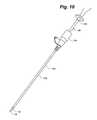
- FIG. 9is a perspective view of an insertion assembly in accordance with the invention.
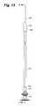
- FIG. 10is a perspective view of an insertion assembly inserted in a sheath in accordance with the present invention with petals partially exposed beyond the sheath;
- FIG. 11is a perspective view of a closure device in the unexpanded state along with a deployment tube in accordance with the invention.
- FIG. 12is a sectional view of a closure device and the deployment tube in accordance with the invention.
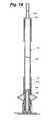
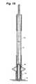
- FIG. 13is an elevational view of a closure device in the expanded state and a deployment tube in accordance with the invention.
- FIG. 14is a sectional view taken along section lines 14 - 14 of FIG. 13 ;
- FIG. 15is a perspective view of the distal end of a delivery tube and petals of the closure device in accordance with the invention.
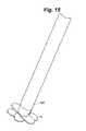
- FIG. 16is a perspective view of a closure device in the expanded state in accordance with the invention and the distal end of a delivery tube;
- FIG. 17is a perspective view of an aperture plate and filament in accordance with an embodiment of the invention.
- FIG. 18is a sectional view of a closure device and the deployment tube as in FIG. 12 including a schematic depiction of a filament routing in accordance with an embodiment of the invention
- FIG. 19is a sectional view as in FIG. 14 including a schematic depiction of a filament routing in accordance with an embodiment of the invention.
- FIG. 20A-Cis a sequential plan view of an alternative embodiment of an external member in accordance with the invention.
- FIG. 21A-Cis a schematic sequential plan view of another alternative embodiment of an external member in accordance with the invention.
- FIG. 22is a plan view of another alternative embodiment of an external member in an elongated state in accordance with the invention.
- FIG. 23is a plan view of another alternative embodiment of an external member in an elongated state in accordance with the invention.
- FIG. 24is a plan view of the alternative embodiment of FIG. 22 or 23 in a deformed expanded state
- FIG. 25is a perspective view of an alternative embodiment of a petal in accordance with the invention.
- FIG. 26is a cross sectional view of the petal depicted in FIG. 25 ;
- FIG. 27is a plan view of the petal depicted in FIGS. 25 and 26 along with other petals;
- FIG. 28is a perspective view of two petals in accordance in an alternative embodiment of the invention.
- FIG. 29is a perspective view of two petals as depicted in FIG. 28 in another angular orientation
- FIG. 30is a plan view of three petals in accordance with another alternative embodiment in accordance with the invention.
- FIG. 31is a cross sectional view of three petals in a parallel orientation as depicted in FIG. 30 ;
- FIG. 32is a plan view of the three petals as depicted in FIGS. 30 and 31 in a fanned out or deployed orientation;
- FIG. 33is a cross sectional view take along section line 33 - 33 of FIG. 32 .
- Absorbable metal closure device 10 of an example embodiment of the invention as depicted in FIGS. 1-16generally includes internal member 12 , external member 14 and filament 16 .
- Internal member 12in one example embodiment, includes two or more petals 18 .
- petals 18are each pierced centrally by at least two apertures 20 .
- the positioning of apertures 20is related to the number of petals and determines the positional relationship of the petals 18 as will be discussed later.
- petals 18include zero degree petal 22 and ninety degree petal 24 .
- zero degree petal 22includes two apertures 20 aligned at approximately zero degrees to a short axis 32 .
- Ninety degree petal 24includes two apertures 20 aligned at approximately ninety degrees to short axis 32 . It is not necessary to practice the invention that the specific angles along which the apertures are aligned given in these examples be used. It is only necessary that the variation between the angles of two related petals 18 be approximately equal to the desired relative rotational difference in position when deployed.
- petals 18include zero degree petal 26 , sixty degree petal 28 and one hundred twenty degree petal 30 .
- Zero degree petal 26includes two apertures aligned at approximately zero degrees to short axis 32 .
- Sixty degree petal 28includes two apertures aligned at approximately sixty degrees to short axis 32 .
- One hundred twenty degree petal 30includes two apertures aligned at approximately one hundred twenty degrees to short axis 32 .
- filament 16passes through apertures 20 of each petal.
- Filament 16has sufficient flexibility so that when filament 16 is slack, petals 18 can be aligned generally parallel to one another prior to insertion.
- Petals 18are dimensioned so as to be able to be passed through a catheter and then through a puncture wound in a blood vessel when they are aligned in a parallel orientation.
- External member 14generally includes stem portion 34 , expandable portion 36 and locking part 38 .
- stem portion 34is a generally cylindrical structure.
- stem portion 34has a diameter approximately equal to the puncture wound to be sealed and which is also approximately equal to the width of petals 18 . That is, stem portion 34 is sized to substantially fill the opening even if the placement of stem portion 34 into the opening alters the shape of the puncture or incision when it is inserted therein.
- Stem portion 34also defines at least one passage 40 therethrough sized to receive two strands of filament 16 either together or separately. Stem portion 34 is arranged along filament 16 , along with petals 18 so that internal face 42 of stem portion 34 abuts to petals 18 when petals 18 are drawn against stem portion 34 by filament 16 . External end 44 of stem portion 34 is arranged to abut expandable portion 36 when filament 16 is tensioned. In one example embodiment, external end 44 is permanently secured at distal end 46 of expandable portion 36 . In one example embodiment, stem portion 34 may be permanently secured to expandable portion 36 such as by welding.
- expandable portion 36generally includes distal portion 48 , proximal portion 50 and expansion portion 52 .
- expandable portion 36may take the form of any elongate hollow cylinder as can be seen in FIGS. 11 and 12 .
- distal portion 48 and proximal portion 50each include a complete portion of the cylinder, which is interrupted by expansion portion 52 .
- Expansion portion 52in this embodiment, is formed by creating two or more slits 54 lengthwise in expandable portion 36 . Between slits 54 remain expansion members 56 . Expansion members 56 may be bowed slightly outward centrally, as seen in FIG. 12 , to facilitate expansion when distal portion 48 and proximal portion 50 move toward one another.
- Example embodiments of the inventionmay include two or more expansion members 56 which are shiftable from an unexpanded orientation to an expanded orientation.
- Example embodimentsinclude four or six expansion members 56 . Shifting of expansion members 56 from an unexpanded orientation to an expanded orientation may be accomplished by deformation of expansion members 56 .
- expansion members 56may be reversibly shiftable. Expansion members 56 may also be created in an expansion portion 52 , for example, by forming slits 54 in a spiral fashion rather than lengthwise relative to expandable portion 36 .
- expansion members 56may include reduced cross-sectional areas 58 located at each end of expansion members 56 and at a central location of expansion members 56 to facilitate deformation of expansion members 56 in a desired way.
- proximal end 60 of expandable portion 36may include an open ended cylinder.
- proximal end 60may be closed by aperture plate 62 , depicted in FIG. 17 .
- Aperture plate 62may include two or more apertures 64 through which filament 16 may pass.
- aperture plate 62includes three apertures 64 so that two strands of filament 16 may be passed in a proximal direction through a first aperture 64 , then in a distal direction through a second aperture 64 , then in a proximal direction again outward through the third aperture 64 and passed under strands of filament 16 where they pass between first aperture 64 and second aperture 64 to act as locking part 38 .
- locking part 38includes wedge 66 and wedge receiver 68 .
- filament 16is passed between wedge 66 and wedge receiver 68 .
- Wedge 66is shiftable relative to wedge receiver 68 so as to allow generally free movement of filament 16 when wedge 66 is spaced from wedge receiver 68 or so as secure filament 16 in at least one direction against movement by friction and compression when wedge 66 is urged toward wedge receiver 68 .
- locking part 38includes cam (not shown.)
- Cam(not shown) is configured to pinch filament 16 against a surface in order to securely lock filament 16 from movement in at least one direction by friction and compression.
- wedge receiver 68is located within stem portion 34 and expandable portion 36 , generally coaxially with stem portion 34 and expandable portion 36 .
- Wedge 66is then located generally coaxially within wedge receiver 68 .
- Wedge 66generally includes tapered distal portion 70 , intermediate shaft 72 , tail portion 74 and proximal cap 76 .
- Tapered distal portion 70generally includes nose portion 78 and sloped portion 80 .
- Nose portion 78may have generally parallel sides 82 followed by sloped portion 80 .
- intermediate shaft 72is a generally cylindrical hollow structure.
- Intermediate shaft 72merges into tail portion 74 , which is smaller in diameter than intermediate shaft 72 and pierced by suture apertures 84 .
- Proximal cap 76is joined to tail portion 74 and sized to abut proximal end 60 of expandable portion 36 .
- Proximal cap 76is also pierced by suture apertures 86 .
- wedge receiver 68defines, on the interior surface thereof, alignment ribs 88 .
- Alignment ribs 88are sized to permit the free but closely aligned passage of wedge 66 within wedge receiver 68 .
- Wedge receiver 68also defines on an inside surface thereof retention ribs 90 .
- Proximal retention rib 92 , intermediate retention rib 94 and distal retention 96are present.
- proximal retention rib 92defines a circular opening of a first size
- intermediate retention rib 94defines a smaller opening than proximal retention rib 92
- distal retention rib 96defines a yet smaller opening than intermediate retention rib 94 .
- proximal cap 76is secured to tail portion 74 of wedge 66 and to proximal end 60 of expansion portion 52 so that wedge 66 and proximal end 60 of expansion portion 52 advance together as expansion portion 52 shifts from an unexpanded status to a expanded status.
- closure device 10 of the present inventionmay be utilized with the assistance of insertion assembly 98 and through preplaced sheath 100 .
- Sheath 100is a generally conventional introducer sheath assembly having a tubular portion 102 and a resilient valve 104 .
- Insertion assembly 98generally includes bypass tube 106 , delivery tube 108 and deployment tube 110 .
- Bypass tube 106is located exteriormost and allows the passage of the remainder of insertion assembly 98 through resilient valve 104 of sheath 100 .
- Delivery tube 108in the depicted example embodiment, includes tubular portion 112 and handle 114 .
- handle 114may include push button release 115 adapted to secure filament 16 therein.
- Tubular portion 112is sized to receive deployment tube 110 therein as well as closure device 10 with expansion portion in the unexpanded state and petals 18 aligned generally parallel to one another and parallel to tubular portion 112 of delivery tube 108 .
- Deployment tube 110is sized to fit within delivery tube 108 and adapted to engage tail portion 74 of wedge 66 as well as proximal portion 50 of expandable portion 36 .
- deployment tube 110generally includes distal end 116 , hollow shaft 118 and proximal end 120 .
- Distal end 116generally includes probe 122 and collar 124 .
- Probe 122extends outwardly away from collar 124 coaxial with hollow shaft 118 in this example embodiment.
- Probe 122is dimensioned to fit within wedge 68 .
- Collar 124is dimensioned to receive hollow shaft 118 therein and pierced by filament apertures 126 proximate the base of probe 122 .
- Filament apertures 126are sized to pass filament 16 therethrough and are located near the junction between probe 122 and collar 124 . Collar 124 is secured to collar shaft 118 .
- Proximal end 120generally includes extension tube 128 and proximal collar 130 .
- Extension tube 128is hollow and sized to receive filament 16 therein in a snuggly fitting relationship.
- Proximal collar 130is sized to be secured to hollow shaft 118 of deployment tube 110 . As such, there is a continuous passage through extension tube 128 , hollow shaft 118 and filament apertures 126 such that filament 116 may pass entirely through deployment tube 110 .
- external member 14includes coiled member 132 and linear member 134 .
- linear member 134is joined to coiled member 132 at eyelet 136 .
- Coiled member 132is extended along linear member 134 for insertion.
- Coiled member 132is expandable by withdrawal of linear member 134 as depicted in FIGS. 20B and 20C .
- FIG. 20Cdepicts coiled member 132 in a fully expanded state.
- Coiled member 132is joined to linear member 134 so that rotation of linear member 134 twists coiled member 132 to adjust the diameter or extended state of coiled member 132 . Twisting in one direction increases the diameter of coiled member 132 . Twisting in the opposed direction decreases the diameter of coiled member 132 .
- external member 14generally includes body 138 , fingers 140 and deformation sleeve 142 .
- Filament 16passes through body 138 and secures this embodiment of external member 14 to internal member 12 .
- Deformation sleeve 142is slidably disposed upon body 138 .
- Deformation sleeve 142is sized to deform FIG. 140 from an open state as depicted in FIGS. 21A and 21B to a closed state depicted in FIG. 21C as deformation sleeve 142 is moved distally along body 138 .
- Deformation sleeve 142may be advanced by use of a tubular push structure (not shown) while tension is held on filament 16 .
- Fingers 140are structured to grip tissue that may be located at the distal end of this embodiment of external member 14 when deformation sleeve 142 is advanced over fingers 140 .
- Metal linear deformable member 144includes elongate body 146 .
- Elongate body 146is pierced by distal aperture 148 , central aperture 150 and proximal aperture 152 .
- Elongate body 146also presents bend facilitators 154 .
- example bend facilitators 154may include crimped or thinned sections 156 .
- Crimped or thinned sections 156may include areas of reduce cross sectional area.
- bend facilitators 154include twists joints 158 . Bend facilitators 154 help control the deformation of elongate body 146 .
- Filament 16may be passed through distal aperture 148 , central aperture 150 and proximal aperture 152 . Filament 16 also helps control the deformation of elongate body 146 .
- metal linear deformable member 144is depicted in a deformed and expanded state after force has been applied along its long axis while holding tension on filament 16 to draw distal aperture 148 into contract with central aperture 150 and central aperture 150 into contact with proximal aperture 152 .
- Bend facilitators 154permit elongate body 146 to be bent to assume, in this example embodiment, a bow tie configuration.
- metal linear deformable member 144expands to secure its location and filament 16 in a tissue tract or in a location external to a blood vessel wall.
- petal 18includes indentation 160 defining pocket 162 .
- Pocket 162may be centrally located and in the depicted embodiment surrounds apertures 20 .
- pocket 162is located to be covered by adjacent petals 18 in the deployed orientation.
- Pocket 162may contain a buffer as described elsewhere in this application.
- FIGS. 28 and 29yet another embodiment of petals 18 is depicted.
- zero degree petal 26is depicted adjacent to large aperture petal 164 .
- FIG. 28depicts zero degree petal 26 oriented displaced approximately ninety degrees from large aperture petal 164 .
- FIG. 29depicts zero degree petal 26 oriented at an acute angle to large aperture petal 164 .
- Large aperture petal 164defines large aperture 166 therethrough. Large aperture 166 is of sufficient size to allow the passage of filament 16 passing through apertures 20 of zero degree petal 26 and to permit free rotation of larger aperture petal 164 about filament 16 relative to zero degree petal 26 .
- large aperture petal 164when unrestricted, large aperture petal 164 , of which there may be more than one, can assume a random orientation relative to zero degree petal 26 .
- ridge petals 168include first ridge petal 170 , second ridge petal 172 and third ridge petal 174 .
- First ridge petal 170includes diagonal ridges 176 .
- Second ridge petal 172includes diagonal ridges 176 at a different angle than first ridge petal 170 .
- Third ridge petal 174includes V-ridges 178 .
- Diagonal ridges 176 and V-ridges 178are oriented to urge first ridge petal 170 , second ridge petal 172 and third ridge petal 174 into an orientation as depicted in FIG. 32 .
- Ridge petals 168are depicted including two apertures 20 in each ridge petals 168 . However, a single aperture 20 is sufficient for ridge petals 168 .
- ridge petals 168are depicted in cross section in a stacked parallel orientation.
- ridge petals 168are depicted in cross section in a fanned out or a deployed orientation.
- closure device 10The operation of closure device 10 will first be described in a general fashion. Thereafter, operation will be described in greater detail.
- closure device 10Prior to insertion into a tissue tract, closure device 10 is arranged in insertion assembly 98 such that filament 16 is doubled and free ends of filament 16 pass through apertures 20 in petals 18 then through stem portion 34 then through expandable portion 36 , through locking part 38 and proximally out through delivery tube 72 leaving a substantial length of free ends of filament 16 available to remain outside of the body when insertion assembly 98 is inserted into a tissue tract.
- Closure device 10is then located in a delivery tube 108 so that petals 18 are aligned substantially parallel lengthwise to one another and parallel to the long axis of delivery tube 108 .
- Petals 18are followed by stem portion 34 followed by expandable portion 36 including locking part 38 , all of which are threaded onto filament 16 .
- Insertion assembly 98 holding closure device 10is then passed through sheath 100 which remains in the tissue tract from the surgical procedure previously performed.
- Deployment tube 110may be used to push closure device 10 forward through delivery tube 108 and through the puncture in the blood vessel wall and into the blood vessel lumen.
- the delivery tube 108 , holding closure device 10is advanced until its distal end is at least partially within the blood vessel which has an incision or a puncture wound in it.
- Closure device 10is then advanced until at least petals 18 and stem portion 34 are within the lumen or beyond the incision.
- filament 16is tensioned from outside of the body of the treated individual. Tensioning filament 16 causes petals 18 to transition from a substantially parallel aligned orientation to a fanned out orientation such that petals 18 are now usually arranged at substantially equal geometric angular orientations. For example, an embodiment including three petals 18 , petals 18 would be oriented at about sixty degree intervals.
- Closure device 10is then withdrawn by tension on filament 16 until petals 18 are approximated against the interior blood vessel wall.
- Stem portion 34then is located within the incision in the blood vessel wall and, in the case of a slit like incision, has caused the incision to attain a cylindrical configuration around stem portion 34 .
- closure device 10in operation, closure device 10 is located within insertion assembly 98 .
- Insertion assembly 98is inserted into sheath 100 which generally remains in place after a vascular puncture procedure has been performed.
- Closure device 10is located within delivery tube 108 .
- Bypass tube 106is located near the distal end of delivery tube 108 .
- Bypass tube 106is fitted into resilient valve 104 thus opening resilient valve 104 to protect against possible damage to closure device 10 and insertion assembly 98 as they pass through resilient valve 104 .
- Insertion assembly 98is advanced through sheath 100 until internal member 12 including petals 18 passes into the lumen of an artery through an incision therein as depicted in FIG. 10 .
- Deployment tube 110is advanced through delivery tube 108 to advance closure device 10 until it is positioned to extend at least petals 18 and a portion of stem portion 44 out of delivery tube 108 into the artery lumen. Once released into the artery lumen, petals 18 tend to self-deploy once freed from delivery tube 108 . This occurs because of the resiliency of filament 16 and because of the flow of blood within the lumen of the blood vessel.
- Petals 18tend to generally align along filament 16 so that apertures 20 falls into line along filament 16 and petals 18 achieve an orientation relative to each other based on the location of apertures 20 in each petal 18 .
- deployment tube 110 and closure device 10including stem portion 34 , expandable portion 36 and locking part 38 remain within the tissue tract.
- Petals 18are located within the lumen of the blood vessel proximate the blood vessel wall. Filament 16 passes through petals 18 , stem portion 34 , expandable portion 36 , locking part 38 and deployment tube 110 .
- Extension tube 128is dimensioned to receive filament 16 closely therein.
- the physicianthen pulls filament 16 tight which pulls petals 18 into apposition against the inner wall of the blood vessel and optionally against delivery tube 108 as seen in FIG. 15 .
- the physicianslightly advances deployment tube 110 while holding tension on filament 16 .
- This actionbrings distal portion 48 and proximal portion 50 of expandable portion 36 toward each other while deforming expansion members 56 outwardly thus causing expansion portion 52 to expand outwardly, transversely relative to the long axis of expansion portion 52 .
- expansion members 56are deformed transversely and outwardly to engage the inner walls of the tissue tract and to resist any inward pulling by petals 18 via filament 16 .
- probe 122 at the end of deployment tube 110is engaged within wedge 66 .
- Wedge 66is forced into wedge receiver 68 while tension is still held on filament 16 .
- filament 16is seized by friction and compression between nose portion 78 and sloped portion 80 of wedge 66 and retention ribs 90 of wedge receiver 68 .
- proximal retention rib 92 , intermediate retention rib 94 and distal retention rib 96filament 16 is securely held between retention ribs 90 and wedge 66 thereby securing petals 18 against stem portion 34 and the blood vessel wall while preventing separation of petals 18 within the blood vessel lumen from stem portion 34 as well as from expandable portion 36 .
- Deployment tube 110is withdrawn from the tissue tract and can be discarded.
- petals 18 and stem portion 34 , and expandable portion 36serve to substantially seal the incision in the blood vessel wall inhibiting any significant leakage.
- stem portion 34is sized to largely fill the incision, whether the incision is circular or slit shaped, in order to facilitate sealing.
- a physicianmay then push down on the percutaneous access site to compress the skin and underlying tissues between the blood vessel puncture and the skin puncture and cut off filament 16 as close as possible to the skin. When pressure is released, filament 16 then withdraws within the tissue tract.
- Closure device 10then is in place.
- Filament 16is formed of a bioresorable material as discussed above; internal member 12 and external member 14 are formed of magnesium or another metal as discussed above.
- Closure device 10then dissolves over a period of time while permitting healing of the puncture in the blood vessel and the tissue tract. As such, blood vessel leakage is prevented; ambulation of the patient is facilitated and healing proceeds in a quicker and more comfortable fashion for the patient.
Landscapes
- Health & Medical Sciences (AREA)
- Surgery (AREA)
- Life Sciences & Earth Sciences (AREA)
- Biomedical Technology (AREA)
- Nuclear Medicine, Radiotherapy & Molecular Imaging (AREA)
- Engineering & Computer Science (AREA)
- Cardiology (AREA)
- Heart & Thoracic Surgery (AREA)
- Medical Informatics (AREA)
- Molecular Biology (AREA)
- Animal Behavior & Ethology (AREA)
- General Health & Medical Sciences (AREA)
- Public Health (AREA)
- Veterinary Medicine (AREA)
- Surgical Instruments (AREA)
Abstract
Description
Claims (9)
Priority Applications (1)
| Application Number | Priority Date | Filing Date | Title |
|---|---|---|---|
| US12/502,034US8252022B2 (en) | 2009-07-13 | 2009-07-13 | Metal vascular aperture closure device |
Applications Claiming Priority (2)
| Application Number | Priority Date | Filing Date | Title |
|---|---|---|---|
| US12/502,034US8252022B2 (en) | 2009-07-13 | 2009-07-13 | Metal vascular aperture closure device |
| US12/501,998US8192456B2 (en) | 2009-07-13 | 2009-07-13 | Metal vascular aperture closure device |
Related Parent Applications (1)
| Application Number | Title | Priority Date | Filing Date |
|---|---|---|---|
| US12/501,998DivisionUS8192456B2 (en) | 2009-07-13 | 2009-07-13 | Metal vascular aperture closure device |
Publications (2)
| Publication Number | Publication Date |
|---|---|
| US20110009901A1 US20110009901A1 (en) | 2011-01-13 |
| US8252022B2true US8252022B2 (en) | 2012-08-28 |
Family
ID=43428062
Family Applications (2)
| Application Number | Title | Priority Date | Filing Date |
|---|---|---|---|
| US12/501,998Expired - Fee RelatedUS8192456B2 (en) | 2009-07-13 | 2009-07-13 | Metal vascular aperture closure device |
| US12/502,034Active2030-12-02US8252022B2 (en) | 2009-07-13 | 2009-07-13 | Metal vascular aperture closure device |
Family Applications Before (1)
| Application Number | Title | Priority Date | Filing Date |
|---|---|---|---|
| US12/501,998Expired - Fee RelatedUS8192456B2 (en) | 2009-07-13 | 2009-07-13 | Metal vascular aperture closure device |
Country Status (1)
| Country | Link |
|---|---|
| US (2) | US8192456B2 (en) |
Cited By (61)
| Publication number | Priority date | Publication date | Assignee | Title |
|---|---|---|---|---|
| US20110178538A1 (en)* | 2010-01-20 | 2011-07-21 | Douglas Wesley Cook | Dial fan hernia mesh system |
| US20110264141A1 (en)* | 2006-02-03 | 2011-10-27 | Biomet Sports Medicine, Llc | Flexible Anchors for Tissue Fixation |
| US20120271349A1 (en)* | 2009-08-25 | 2012-10-25 | Redline Orthopedic Innovations, Llc | Suture Anchor and Method of Use |
| US8317825B2 (en) | 2004-11-09 | 2012-11-27 | Biomet Sports Medicine, Llc | Soft tissue conduit device and method |
| US8343227B2 (en) | 2009-05-28 | 2013-01-01 | Biomet Manufacturing Corp. | Knee prosthesis assembly with ligament link |
| US8361113B2 (en) | 2006-02-03 | 2013-01-29 | Biomet Sports Medicine, Llc | Method and apparatus for coupling soft tissue to a bone |
| US8409253B2 (en) | 2006-02-03 | 2013-04-02 | Biomet Sports Medicine, Llc | Soft tissue repair assembly and associated method |
| US8500818B2 (en) | 2006-09-29 | 2013-08-06 | Biomet Manufacturing, Llc | Knee prosthesis assembly with ligament link |
| US8551140B2 (en) | 2004-11-05 | 2013-10-08 | Biomet Sports Medicine, Llc | Method and apparatus for coupling soft tissue to bone |
| US8562645B2 (en) | 2006-09-29 | 2013-10-22 | Biomet Sports Medicine, Llc | Method and apparatus for forming a self-locking adjustable loop |
| US8562647B2 (en) | 2006-09-29 | 2013-10-22 | Biomet Sports Medicine, Llc | Method and apparatus for securing soft tissue to bone |
| US8574235B2 (en) | 2006-02-03 | 2013-11-05 | Biomet Sports Medicine, Llc | Method for trochanteric reattachment |
| US8597327B2 (en) | 2006-02-03 | 2013-12-03 | Biomet Manufacturing, Llc | Method and apparatus for sternal closure |
| US8608777B2 (en) | 2006-02-03 | 2013-12-17 | Biomet Sports Medicine | Method and apparatus for coupling soft tissue to a bone |
| US8632569B2 (en) | 2006-02-03 | 2014-01-21 | Biomet Sports Medicine, Llc | Soft tissue repair device and associated methods |
| US8652171B2 (en) | 2006-02-03 | 2014-02-18 | Biomet Sports Medicine, Llc | Method and apparatus for soft tissue fixation |
| US8672968B2 (en) | 2006-09-29 | 2014-03-18 | Biomet Sports Medicine, Llc | Method for implanting soft tissue |
| US8771352B2 (en) | 2011-05-17 | 2014-07-08 | Biomet Sports Medicine, Llc | Method and apparatus for tibial fixation of an ACL graft |
| US8777956B2 (en) | 2006-08-16 | 2014-07-15 | Biomet Sports Medicine, Llc | Chondral defect repair |
| US8801783B2 (en) | 2006-09-29 | 2014-08-12 | Biomet Sports Medicine, Llc | Prosthetic ligament system for knee joint |
| US8840645B2 (en) | 2004-11-05 | 2014-09-23 | Biomet Sports Medicine, Llc | Method and apparatus for coupling soft tissue to a bone |
| US8932331B2 (en) | 2006-02-03 | 2015-01-13 | Biomet Sports Medicine, Llc | Method and apparatus for coupling soft tissue to bone |
| US8936621B2 (en) | 2006-02-03 | 2015-01-20 | Biomet Sports Medicine, Llc | Method and apparatus for forming a self-locking adjustable loop |
| US8998949B2 (en) | 2004-11-09 | 2015-04-07 | Biomet Sports Medicine, Llc | Soft tissue conduit device |
| US9017381B2 (en) | 2007-04-10 | 2015-04-28 | Biomet Sports Medicine, Llc | Adjustable knotless loops |
| WO2015059567A2 (en) | 2013-10-23 | 2015-04-30 | Calore Medical Ltd. | Expandable medical anchor device formed of cut metal tube |
| US9149267B2 (en) | 2006-02-03 | 2015-10-06 | Biomet Sports Medicine, Llc | Method and apparatus for coupling soft tissue to a bone |
| US9173651B2 (en) | 2006-02-03 | 2015-11-03 | Biomet Sports Medicine, Llc | Soft tissue repair device and associated methods |
| US9301766B2 (en) | 2011-06-27 | 2016-04-05 | Biomet Sports Medicine, Llc | Apparatus for repairing bone defects |
| US9314241B2 (en) | 2011-11-10 | 2016-04-19 | Biomet Sports Medicine, Llc | Apparatus for coupling soft tissue to a bone |
| US9357991B2 (en) | 2011-11-03 | 2016-06-07 | Biomet Sports Medicine, Llc | Method and apparatus for stitching tendons |
| US9370350B2 (en) | 2011-11-10 | 2016-06-21 | Biomet Sports Medicine, Llc | Apparatus for coupling soft tissue to a bone |
| US9381013B2 (en) | 2011-11-10 | 2016-07-05 | Biomet Sports Medicine, Llc | Method for coupling soft tissue to a bone |
| US9402621B2 (en) | 2006-02-03 | 2016-08-02 | Biomet Sports Medicine, LLC. | Method for tissue fixation |
| US9445827B2 (en) | 2011-10-25 | 2016-09-20 | Biomet Sports Medicine, Llc | Method and apparatus for intraosseous membrane reconstruction |
| US9504460B2 (en) | 2004-11-05 | 2016-11-29 | Biomet Sports Medicine, LLC. | Soft tissue repair device and method |
| US9538998B2 (en) | 2006-02-03 | 2017-01-10 | Biomet Sports Medicine, Llc | Method and apparatus for fracture fixation |
| US9572655B2 (en) | 2004-11-05 | 2017-02-21 | Biomet Sports Medicine, Llc | Method and apparatus for coupling soft tissue to a bone |
| US9615822B2 (en) | 2014-05-30 | 2017-04-11 | Biomet Sports Medicine, Llc | Insertion tools and method for soft anchor |
| US9693786B2 (en) | 2011-06-27 | 2017-07-04 | Biomet Sports Medicine, Llc | Method for repairing bone defects |
| US9700291B2 (en) | 2014-06-03 | 2017-07-11 | Biomet Sports Medicine, Llc | Capsule retractor |
| US9757119B2 (en) | 2013-03-08 | 2017-09-12 | Biomet Sports Medicine, Llc | Visual aid for identifying suture limbs arthroscopically |
| US9788876B2 (en) | 2006-09-29 | 2017-10-17 | Biomet Sports Medicine, Llc | Fracture fixation device |
| US9801708B2 (en) | 2004-11-05 | 2017-10-31 | Biomet Sports Medicine, Llc | Method and apparatus for coupling soft tissue to a bone |
| US9918827B2 (en) | 2013-03-14 | 2018-03-20 | Biomet Sports Medicine, Llc | Scaffold for spring ligament repair |
| US9918826B2 (en) | 2006-09-29 | 2018-03-20 | Biomet Sports Medicine, Llc | Scaffold for spring ligament repair |
| US9955980B2 (en) | 2015-02-24 | 2018-05-01 | Biomet Sports Medicine, Llc | Anatomic soft tissue repair |
| US10004588B2 (en) | 2006-02-03 | 2018-06-26 | Biomet Sports Medicine, Llc | Method and apparatus for fixation of an ACL graft |
| US10016188B2 (en) | 2015-02-10 | 2018-07-10 | Teleflex Innovation S.à.r.l. | Closure device for sealing percutaneous opening in a vessel |
| US10039543B2 (en) | 2014-08-22 | 2018-08-07 | Biomet Sports Medicine, Llc | Non-sliding soft anchor |
| US10136886B2 (en) | 2013-12-20 | 2018-11-27 | Biomet Sports Medicine, Llc | Knotless soft tissue devices and techniques |
| US10349931B2 (en) | 2006-09-29 | 2019-07-16 | Biomet Sports Medicine, Llc | Fracture fixation device |
| US10517587B2 (en) | 2006-02-03 | 2019-12-31 | Biomet Sports Medicine, Llc | Method and apparatus for forming a self-locking adjustable loop |
| US10912551B2 (en) | 2015-03-31 | 2021-02-09 | Biomet Sports Medicine, Llc | Suture anchor with soft anchor of electrospun fibers |
| US11259794B2 (en) | 2006-09-29 | 2022-03-01 | Biomet Sports Medicine, Llc | Method for implanting soft tissue |
| US11259792B2 (en) | 2006-02-03 | 2022-03-01 | Biomet Sports Medicine, Llc | Method and apparatus for coupling anatomical features |
| US11311287B2 (en) | 2006-02-03 | 2022-04-26 | Biomet Sports Medicine, Llc | Method for tissue fixation |
| US12096928B2 (en) | 2009-05-29 | 2024-09-24 | Biomet Sports Medicine, Llc | Method and apparatus for coupling soft tissue to a bone |
| US12245759B2 (en) | 2008-08-22 | 2025-03-11 | Biomet Sports Medicine, Llc | Method and apparatus for coupling soft tissue to bone |
| US12329373B2 (en) | 2011-05-02 | 2025-06-17 | Biomet Sports Medicine, Llc | Method and apparatus for soft tissue fixation |
| US12419632B2 (en) | 2008-08-22 | 2025-09-23 | Biomet Sports Medicine, Llc | Method and apparatus for coupling anatomical features |
Families Citing this family (10)
| Publication number | Priority date | Publication date | Assignee | Title |
|---|---|---|---|---|
| EP2717781B1 (en) | 2011-06-07 | 2019-02-06 | St. Jude Medical Puerto Rico LLC | Large bore closure device |
| EP2747667B1 (en) | 2011-11-16 | 2016-03-09 | St. Jude Medical Puerto Rico LLC | Vascular closure system |
| WO2013074490A1 (en) | 2011-11-16 | 2013-05-23 | St. Jude Medical Puerto Rico Llc | Large bore vascular closure device with inner and outer seals |
| WO2013081905A1 (en)* | 2011-11-28 | 2013-06-06 | St. Jude Medical Puerto Rico Llc | Anchor device for large bore vascular closure |
| US9358077B2 (en) | 2012-03-14 | 2016-06-07 | St. Jude Medical Puerto Rico Llc | Markers for tissue tract depth indication and methods |
| WO2014021937A1 (en) | 2012-08-03 | 2014-02-06 | St. Jude Medical Puerto Rico Llc | Large bore introducer with improved seal |
| WO2014031147A1 (en) | 2012-08-24 | 2014-02-27 | St. Jude Medical Puerto Rico Llc | Balloon bailout and bioadhesive delivery device for suture based closure and methods |
| CN102895008B (en)* | 2012-09-28 | 2015-12-02 | 上海形状记忆合金材料有限公司 | Medical occluder and induction system thereof |
| US10136885B2 (en) | 2013-03-11 | 2018-11-27 | St. Jude Medical Puerto Rico Llc | Three suture large bore closure device and methods |
| US9055933B2 (en) | 2013-03-12 | 2015-06-16 | St. Jude Medical Puerto Rico Llc | Large bore closure secondary hemostasis bioadhesive delivery systems and methods |
Citations (64)
| Publication number | Priority date | Publication date | Assignee | Title |
|---|---|---|---|---|
| DE233303C (en) | 1911-04-05 | |||
| US3874388A (en) | 1973-02-12 | 1975-04-01 | Ochsner Med Found Alton | Shunt defect closure system |
| SU1055520A1 (en) | 1982-01-13 | 1983-11-23 | Sharapov Vladimir F | Oburator for temporary closure of intenstinal fistula |
| SU1088709A1 (en) | 1981-02-10 | 1984-04-30 | Институт Клинической И Экспериментальной Хирургии | Method of treatment of stomach fistula |
| US4614945A (en) | 1985-02-20 | 1986-09-30 | Diversified Energies, Inc. | Automatic/remote RF instrument reading method and apparatus |
| US4669473A (en) | 1985-09-06 | 1987-06-02 | Acufex Microsurgical, Inc. | Surgical fastener |
| US4744364A (en) | 1987-02-17 | 1988-05-17 | Intravascular Surgical Instruments, Inc. | Device for sealing percutaneous puncture in a vessel |
| FR2607706A1 (en) | 1986-12-05 | 1988-06-10 | Lefebvre Jean Marie | Device for percutaneous vascular blocking allowing medicinal infusions, and method for percutaneous vascular blocking employing the said device |
| US4852568A (en) | 1987-02-17 | 1989-08-01 | Kensey Nash Corporation | Method and apparatus for sealing an opening in tissue of a living being |
| US4890612A (en) | 1987-02-17 | 1990-01-02 | Kensey Nash Corporation | Device for sealing percutaneous puncture in a vessel |
| US5021059A (en) | 1990-05-07 | 1991-06-04 | Kensey Nash Corporation | Plug device with pulley for sealing punctures in tissue and methods of use |
| US5061274A (en) | 1989-12-04 | 1991-10-29 | Kensey Nash Corporation | Plug device for sealing openings and method of use |
| US5108421A (en) | 1990-10-01 | 1992-04-28 | Quinton Instrument Company | Insertion assembly and method of inserting a vessel plug into the body of a patient |
| US5192300A (en) | 1990-10-01 | 1993-03-09 | Quinton Instrument Company | Insertion assembly and method of inserting a vessel plug into the body of a patient |
| US5192302A (en) | 1989-12-04 | 1993-03-09 | Kensey Nash Corporation | Plug devices for sealing punctures and methods of use |
| US5192301A (en) | 1989-01-17 | 1993-03-09 | Nippon Zeon Co., Ltd. | Closing plug of a defect for medical use and a closing plug device utilizing it |
| US5222974A (en) | 1991-11-08 | 1993-06-29 | Kensey Nash Corporation | Hemostatic puncture closure system and method of use |
| US5272616A (en) | 1992-04-21 | 1993-12-21 | Wisconsin Alumni Research Foundation | Single phase to three phase power converter for motor loads |
| US5282827A (en) | 1991-11-08 | 1994-02-01 | Kensey Nash Corporation | Hemostatic puncture closure system and method of use |
| US5312435A (en) | 1993-05-17 | 1994-05-17 | Kensey Nash Corporation | Fail predictable, reinforced anchor for hemostatic puncture closure |
| US5318040A (en) | 1992-08-27 | 1994-06-07 | Kensey Nash Corporation | Instruments and methods for performing medical procedures via small percutaneous incisions or punctures without using a trocar |
| US5324306A (en) | 1991-10-30 | 1994-06-28 | Howmedica, Inc. | Hemostatic implant introducer |
| US5342393A (en) | 1992-08-27 | 1994-08-30 | Duke University | Method and device for vascular repair |
| US5350399A (en)* | 1991-09-23 | 1994-09-27 | Jay Erlebacher | Percutaneous arterial puncture seal device and insertion tool therefore |
| US5383897A (en) | 1992-10-19 | 1995-01-24 | Shadyside Hospital | Method and apparatus for closing blood vessel punctures |
| US5383886A (en) | 1992-10-13 | 1995-01-24 | Kensey Nash Corporation | Methods and instruments for performing medical procedures percutaneously without a trocar |
| USRE34866E (en) | 1987-02-17 | 1995-02-21 | Kensey Nash Corporation | Device for sealing percutaneous puncture in a vessel |
| US5391183A (en) | 1990-09-21 | 1995-02-21 | Datascope Investment Corp | Device and method sealing puncture wounds |
| US5403278A (en) | 1992-04-15 | 1995-04-04 | Datascope Investment Corp. | Device and method for treating hematomas and false aneurysms |
| US5411520A (en) | 1991-11-08 | 1995-05-02 | Kensey Nash Corporation | Hemostatic vessel puncture closure system utilizing a plug located within the puncture tract spaced from the vessel, and method of use |
| US5454833A (en) | 1993-07-21 | 1995-10-03 | Laboratoire, Nycomed S.A. | System for temporarily obturating an orifice in a perforated organ, such as a vessel |
| US5507744A (en) | 1992-04-23 | 1996-04-16 | Scimed Life Systems, Inc. | Apparatus and method for sealing vascular punctures |
| US5523291A (en) | 1993-09-07 | 1996-06-04 | Datascope Investment Corp. | Injectable compositions for soft tissue augmentation |
| US5531757A (en) | 1992-10-30 | 1996-07-02 | Kensey; Kenneth | Methods and stabilized instruments for performing medical procedures percutaneously without a trocar |
| US5531759A (en) | 1994-04-29 | 1996-07-02 | Kensey Nash Corporation | System for closing a percutaneous puncture formed by a trocar to prevent tissue at the puncture from herniating |
| US5545178A (en) | 1994-04-29 | 1996-08-13 | Kensey Nash Corporation | System for closing a percutaneous puncture formed by a trocar to prevent tissue at the puncture from herniating |
| US5549633A (en) | 1994-08-24 | 1996-08-27 | Kensey Nash Corporation | Apparatus and methods of use for preventing blood seepage at a percutaneous puncture site |
| US5593422A (en) | 1989-05-29 | 1997-01-14 | Muijs Van De Moer; Wouter M. | Occlusion assembly for sealing openings in blood vessels and a method for sealing openings in blood vessels |
| US5620461A (en) | 1989-05-29 | 1997-04-15 | Muijs Van De Moer; Wouter M. | Sealing device |
| US5643317A (en) | 1992-11-25 | 1997-07-01 | William Cook Europe S.A. | Closure prosthesis for transcatheter placement |
| US5645566A (en) | 1995-09-15 | 1997-07-08 | Sub Q Inc. | Apparatus and method for percutaneous sealing of blood vessel punctures |
| US5649959A (en) | 1995-02-10 | 1997-07-22 | Sherwood Medical Company | Assembly for sealing a puncture in a vessel |
| US5662681A (en) | 1996-04-23 | 1997-09-02 | Kensey Nash Corporation | Self locking closure for sealing percutaneous punctures |
| US5676689A (en) | 1991-11-08 | 1997-10-14 | Kensey Nash Corporation | Hemostatic puncture closure system including vessel location device and method of use |
| US5676698A (en) | 1993-09-07 | 1997-10-14 | Datascope Investment Corp. | Soft tissue implant |
| US5690674A (en) | 1996-07-02 | 1997-11-25 | Cordis Corporation | Wound closure with plug |
| US5700277A (en) | 1993-06-04 | 1997-12-23 | Kensey Nash Corporation | Hemostatic vessel puncture closure with filament lock |
| US5725521A (en) | 1996-03-29 | 1998-03-10 | Eclipse Surgical Technologies, Inc. | Depth stop apparatus and method for laser-assisted transmyocardial revascularization and other surgical applications |
| US5746755A (en) | 1994-06-01 | 1998-05-05 | Perclose, Inc. | Method and device for providing hemostasis at vascular penetration sites |
| US5782860A (en) | 1997-02-11 | 1998-07-21 | Biointerventional Corporation | Closure device for percutaneous occlusion of puncture sites and tracts in the human body and method |
| US5810810A (en) | 1992-04-23 | 1998-09-22 | Scimed Life Systems, Inc. | Apparatus and method for sealing vascular punctures |
| US5951589A (en) | 1997-02-11 | 1999-09-14 | Biointerventional Corporation | Expansile device for use in blood vessels and tracts in the body and tension application device for use therewith and method |
| US6063085A (en) | 1992-04-23 | 2000-05-16 | Scimed Life Systems, Inc. | Apparatus and method for sealing vascular punctures |
| US6162192A (en) | 1998-05-01 | 2000-12-19 | Sub Q, Inc. | System and method for facilitating hemostasis of blood vessel punctures with absorbable sponge |
| US6190400B1 (en) | 1991-10-22 | 2001-02-20 | Kensey Nash Corporation | Blood vessel sealing device and method of sealing an opening in a blood vessel |
| US6325789B1 (en) | 1990-12-27 | 2001-12-04 | Datascope Investment Corporation | Device and method for sealing puncture wounds |
| US6334865B1 (en) | 1998-08-04 | 2002-01-01 | Fusion Medical Technologies, Inc. | Percutaneous tissue track closure assembly and method |
| US6764500B1 (en) | 1989-05-29 | 2004-07-20 | Kensey Nash Corporation | Sealing device |
| US7008439B1 (en) | 1990-09-21 | 2006-03-07 | Datascope Investments Corp. | Device and method for sealing puncture wounds |
| US20070135842A1 (en) | 1991-10-22 | 2007-06-14 | Kensey Nash Corporation | Sealing device |
| US20070244518A1 (en) | 2003-07-14 | 2007-10-18 | Nmt Medical, Inc. | Patent foramen ovale (PFO) closure device with linearly elongating petals |
| US20100076544A1 (en)* | 2007-01-30 | 2010-03-25 | Erika Hoffmann | Biodegradable vascular support |
| US7842069B2 (en)* | 2004-05-07 | 2010-11-30 | Nmt Medical, Inc. | Inflatable occluder |
| US8114125B2 (en)* | 2002-07-31 | 2012-02-14 | Abbott Laboratories Vascular Enterprises Limited | Apparatus for sealing surgical punctures |
- 2009
- 2009-07-13USUS12/501,998patent/US8192456B2/ennot_activeExpired - Fee Related
- 2009-07-13USUS12/502,034patent/US8252022B2/enactiveActive
Patent Citations (94)
| Publication number | Priority date | Publication date | Assignee | Title |
|---|---|---|---|---|
| DE233303C (en) | 1911-04-05 | |||
| US3874388A (en) | 1973-02-12 | 1975-04-01 | Ochsner Med Found Alton | Shunt defect closure system |
| SU1088709A1 (en) | 1981-02-10 | 1984-04-30 | Институт Клинической И Экспериментальной Хирургии | Method of treatment of stomach fistula |
| SU1055520A1 (en) | 1982-01-13 | 1983-11-23 | Sharapov Vladimir F | Oburator for temporary closure of intenstinal fistula |
| US4614945A (en) | 1985-02-20 | 1986-09-30 | Diversified Energies, Inc. | Automatic/remote RF instrument reading method and apparatus |
| US4669473A (en) | 1985-09-06 | 1987-06-02 | Acufex Microsurgical, Inc. | Surgical fastener |
| FR2607706A1 (en) | 1986-12-05 | 1988-06-10 | Lefebvre Jean Marie | Device for percutaneous vascular blocking allowing medicinal infusions, and method for percutaneous vascular blocking employing the said device |
| US4852568A (en) | 1987-02-17 | 1989-08-01 | Kensey Nash Corporation | Method and apparatus for sealing an opening in tissue of a living being |
| US4890612A (en) | 1987-02-17 | 1990-01-02 | Kensey Nash Corporation | Device for sealing percutaneous puncture in a vessel |
| USRE34866E (en) | 1987-02-17 | 1995-02-21 | Kensey Nash Corporation | Device for sealing percutaneous puncture in a vessel |
| US4744364A (en) | 1987-02-17 | 1988-05-17 | Intravascular Surgical Instruments, Inc. | Device for sealing percutaneous puncture in a vessel |
| US5192301A (en) | 1989-01-17 | 1993-03-09 | Nippon Zeon Co., Ltd. | Closing plug of a defect for medical use and a closing plug device utilizing it |
| US6764500B1 (en) | 1989-05-29 | 2004-07-20 | Kensey Nash Corporation | Sealing device |
| US5593422A (en) | 1989-05-29 | 1997-01-14 | Muijs Van De Moer; Wouter M. | Occlusion assembly for sealing openings in blood vessels and a method for sealing openings in blood vessels |
| US5620461A (en) | 1989-05-29 | 1997-04-15 | Muijs Van De Moer; Wouter M. | Sealing device |
| US5916236A (en) | 1989-05-29 | 1999-06-29 | Kensey Nash Corporation | Occlusion assembly for sealing openings in blood vessels and a method for sealing openings in blood vessels |
| US7169168B2 (en) | 1989-05-29 | 2007-01-30 | Kensey Nash Corporation | Sealing device |
| US5061274A (en) | 1989-12-04 | 1991-10-29 | Kensey Nash Corporation | Plug device for sealing openings and method of use |
| US5192302A (en) | 1989-12-04 | 1993-03-09 | Kensey Nash Corporation | Plug devices for sealing punctures and methods of use |
| US5021059A (en) | 1990-05-07 | 1991-06-04 | Kensey Nash Corporation | Plug device with pulley for sealing punctures in tissue and methods of use |
| US5741223A (en) | 1990-09-21 | 1998-04-21 | Datascope Investment Corp. | Device and method for sealing puncture wounds |
| US5830130A (en) | 1990-09-21 | 1998-11-03 | Datascope Investment Corp. | Device and method for sealing puncture wounds |
| US5591204A (en) | 1990-09-21 | 1997-01-07 | Datascope Investment Corp. | Device and method for sealing puncture wounds |
| US5391183A (en) | 1990-09-21 | 1995-02-21 | Datascope Investment Corp | Device and method sealing puncture wounds |
| US7008439B1 (en) | 1990-09-21 | 2006-03-07 | Datascope Investments Corp. | Device and method for sealing puncture wounds |
| US5948425A (en) | 1990-09-21 | 1999-09-07 | Datascope Investment Corp. | Device and method for sealing puncture wounds |
| US5437631A (en) | 1990-09-21 | 1995-08-01 | Datascope Investment Corp. | Percutaneous introducer set and method for sealing puncture wounds |
| US5725498A (en) | 1990-09-21 | 1998-03-10 | Datascope Investment Corp. | Device and method for sealing puncture wounds |
| US5716375A (en) | 1990-10-01 | 1998-02-10 | Quinton Instrument Company | Insertion assembly and method of inserting a vessel plug into the body of a patient |
| US5192300A (en) | 1990-10-01 | 1993-03-09 | Quinton Instrument Company | Insertion assembly and method of inserting a vessel plug into the body of a patient |
| US5478352A (en) | 1990-10-01 | 1995-12-26 | Quinton Instrument Company | Insertion assembly and method of inserting a vessel plug into the body of a patient |
| US5275616B1 (en) | 1990-10-01 | 1996-01-23 | Quinton Instr | Insertion assembly and method of inserting a vessel plug into the body of a patient |
| US5108421A (en) | 1990-10-01 | 1992-04-28 | Quinton Instrument Company | Insertion assembly and method of inserting a vessel plug into the body of a patient |
| US5601602A (en) | 1990-10-01 | 1997-02-11 | Quinton Instrument Company | Insertion assembly and method of inserting a vessel plug into the body of a patient |
| US5275616A (en) | 1990-10-01 | 1994-01-04 | Quinton Instrument Company | Insertion assembly and method of inserting a vessel plug into the body of a patient |
| US5591205A (en) | 1990-10-01 | 1997-01-07 | Quinton Instrument Company | Insertion assembly and method of inserting a vessel plug into the body of a patient |
| US6325789B1 (en) | 1990-12-27 | 2001-12-04 | Datascope Investment Corporation | Device and method for sealing puncture wounds |
| US5350399A (en)* | 1991-09-23 | 1994-09-27 | Jay Erlebacher | Percutaneous arterial puncture seal device and insertion tool therefore |
| US20070135842A1 (en) | 1991-10-22 | 2007-06-14 | Kensey Nash Corporation | Sealing device |
| US6190400B1 (en) | 1991-10-22 | 2001-02-20 | Kensey Nash Corporation | Blood vessel sealing device and method of sealing an opening in a blood vessel |
| US5324306A (en) | 1991-10-30 | 1994-06-28 | Howmedica, Inc. | Hemostatic implant introducer |
| US5935147A (en) | 1991-11-08 | 1999-08-10 | Kensey Nash Corporation | Hemostatic puncture closure system and method of use |
| US5861004A (en) | 1991-11-08 | 1999-01-19 | Kensey Nash Corporation | Hemostatic puncture closure system including closure locking means and method of use |
| US5411520A (en) | 1991-11-08 | 1995-05-02 | Kensey Nash Corporation | Hemostatic vessel puncture closure system utilizing a plug located within the puncture tract spaced from the vessel, and method of use |
| US5282827A (en) | 1991-11-08 | 1994-02-01 | Kensey Nash Corporation | Hemostatic puncture closure system and method of use |
| US20010003158A1 (en) | 1991-11-08 | 2001-06-07 | Kensey Nash Corporation | Hemostatic puncture closure system and method of use |
| US5707393A (en) | 1991-11-08 | 1998-01-13 | Kensey Nash Corporation | Hemostatic puncture closure system and method of use |
| US6179863B1 (en) | 1991-11-08 | 2001-01-30 | Kensey Nash Corporation | Hemostatic puncture closure system and method of use |
| US6090130A (en) | 1991-11-08 | 2000-07-18 | Kensey Nash Corporation | Hemostatic puncture closure system including blood vessel locator and method of use |
| US5222974A (en) | 1991-11-08 | 1993-06-29 | Kensey Nash Corporation | Hemostatic puncture closure system and method of use |
| US5676689A (en) | 1991-11-08 | 1997-10-14 | Kensey Nash Corporation | Hemostatic puncture closure system including vessel location device and method of use |
| US6045569A (en) | 1991-11-08 | 2000-04-04 | Kensey Nash Corporation | Hemostatic puncture closure system including closure locking means and methods of use |
| US6007563A (en) | 1991-11-08 | 1999-12-28 | Kensey Nash Corporation | Method of deploying percutaneous puncture closure |
| US5441517A (en) | 1991-11-08 | 1995-08-15 | Kensey Nash Corporation | Hemostatic puncture closure system and method of use |
| US5403278A (en) | 1992-04-15 | 1995-04-04 | Datascope Investment Corp. | Device and method for treating hematomas and false aneurysms |
| US5272616A (en) | 1992-04-21 | 1993-12-21 | Wisconsin Alumni Research Foundation | Single phase to three phase power converter for motor loads |
| US6063085A (en) | 1992-04-23 | 2000-05-16 | Scimed Life Systems, Inc. | Apparatus and method for sealing vascular punctures |
| US5810810A (en) | 1992-04-23 | 1998-09-22 | Scimed Life Systems, Inc. | Apparatus and method for sealing vascular punctures |
| US5507744A (en) | 1992-04-23 | 1996-04-16 | Scimed Life Systems, Inc. | Apparatus and method for sealing vascular punctures |
| US5342393A (en) | 1992-08-27 | 1994-08-30 | Duke University | Method and device for vascular repair |
| US5318040A (en) | 1992-08-27 | 1994-06-07 | Kensey Nash Corporation | Instruments and methods for performing medical procedures via small percutaneous incisions or punctures without using a trocar |
| US5383886A (en) | 1992-10-13 | 1995-01-24 | Kensey Nash Corporation | Methods and instruments for performing medical procedures percutaneously without a trocar |
| US5383897A (en) | 1992-10-19 | 1995-01-24 | Shadyside Hospital | Method and apparatus for closing blood vessel punctures |
| US5531757A (en) | 1992-10-30 | 1996-07-02 | Kensey; Kenneth | Methods and stabilized instruments for performing medical procedures percutaneously without a trocar |
| US5643317A (en) | 1992-11-25 | 1997-07-01 | William Cook Europe S.A. | Closure prosthesis for transcatheter placement |
| US5947997A (en) | 1992-11-25 | 1999-09-07 | William Cook Europe A/S | Closure prothesis for transcatheter placement |
| US5312435A (en) | 1993-05-17 | 1994-05-17 | Kensey Nash Corporation | Fail predictable, reinforced anchor for hemostatic puncture closure |
| US5700277A (en) | 1993-06-04 | 1997-12-23 | Kensey Nash Corporation | Hemostatic vessel puncture closure with filament lock |
| US5454833A (en) | 1993-07-21 | 1995-10-03 | Laboratoire, Nycomed S.A. | System for temporarily obturating an orifice in a perforated organ, such as a vessel |
| US5922024A (en) | 1993-09-07 | 1999-07-13 | Datascope Investment Corp. | Soft tissue implant |
| US5523291A (en) | 1993-09-07 | 1996-06-04 | Datascope Investment Corp. | Injectable compositions for soft tissue augmentation |
| US5705488A (en) | 1993-09-07 | 1998-01-06 | Datascope Investment Corp. | Injectable compositions for soft tissue augmentation |
| US5676698A (en) | 1993-09-07 | 1997-10-14 | Datascope Investment Corp. | Soft tissue implant |
| US5531759A (en) | 1994-04-29 | 1996-07-02 | Kensey Nash Corporation | System for closing a percutaneous puncture formed by a trocar to prevent tissue at the puncture from herniating |
| US5545178A (en) | 1994-04-29 | 1996-08-13 | Kensey Nash Corporation | System for closing a percutaneous puncture formed by a trocar to prevent tissue at the puncture from herniating |
| US5746755A (en) | 1994-06-01 | 1998-05-05 | Perclose, Inc. | Method and device for providing hemostasis at vascular penetration sites |
| US5681334A (en) | 1994-08-24 | 1997-10-28 | Kensey Nash Corporation | Apparatus and methods of use for preventing blood seepage at a percutaneous puncture site |
| US5728114A (en) | 1994-08-24 | 1998-03-17 | Kensey Nash Corporation | Apparatus and methods of use for preventing blood seepage at a percutaneous puncture site |
| US5549633A (en) | 1994-08-24 | 1996-08-27 | Kensey Nash Corporation | Apparatus and methods of use for preventing blood seepage at a percutaneous puncture site |
| US5649959A (en) | 1995-02-10 | 1997-07-22 | Sherwood Medical Company | Assembly for sealing a puncture in a vessel |
| US5645566A (en) | 1995-09-15 | 1997-07-08 | Sub Q Inc. | Apparatus and method for percutaneous sealing of blood vessel punctures |
| US5725521A (en) | 1996-03-29 | 1998-03-10 | Eclipse Surgical Technologies, Inc. | Depth stop apparatus and method for laser-assisted transmyocardial revascularization and other surgical applications |
| US5662681A (en) | 1996-04-23 | 1997-09-02 | Kensey Nash Corporation | Self locking closure for sealing percutaneous punctures |
| US5690674A (en) | 1996-07-02 | 1997-11-25 | Cordis Corporation | Wound closure with plug |
| US5951589A (en) | 1997-02-11 | 1999-09-14 | Biointerventional Corporation | Expansile device for use in blood vessels and tracts in the body and tension application device for use therewith and method |
| US5922009A (en) | 1997-02-11 | 1999-07-13 | Biointerventional Coporation | Expansile device for use in blood vessels and tracts in the body and tension application device for use therewith and method |
| US5782860A (en) | 1997-02-11 | 1998-07-21 | Biointerventional Corporation | Closure device for percutaneous occlusion of puncture sites and tracts in the human body and method |
| US6162192A (en) | 1998-05-01 | 2000-12-19 | Sub Q, Inc. | System and method for facilitating hemostasis of blood vessel punctures with absorbable sponge |
| US6334865B1 (en) | 1998-08-04 | 2002-01-01 | Fusion Medical Technologies, Inc. | Percutaneous tissue track closure assembly and method |
| US8114125B2 (en)* | 2002-07-31 | 2012-02-14 | Abbott Laboratories Vascular Enterprises Limited | Apparatus for sealing surgical punctures |
| US8118833B2 (en)* | 2002-07-31 | 2012-02-21 | Abbott Laboratories Vascular Enterprises Limited | Apparatus for sealing surgical punctures |
| US20070244518A1 (en) | 2003-07-14 | 2007-10-18 | Nmt Medical, Inc. | Patent foramen ovale (PFO) closure device with linearly elongating petals |
| US7842069B2 (en)* | 2004-05-07 | 2010-11-30 | Nmt Medical, Inc. | Inflatable occluder |
| US20100076544A1 (en)* | 2007-01-30 | 2010-03-25 | Erika Hoffmann | Biodegradable vascular support |
Non-Patent Citations (1)
| Title |
|---|
| U.S. Appl. No. 12/501,998, filed Jul. 13, 2009, Tom Holman et al. |
Cited By (162)
| Publication number | Priority date | Publication date | Assignee | Title |
|---|---|---|---|---|
| US8840645B2 (en) | 2004-11-05 | 2014-09-23 | Biomet Sports Medicine, Llc | Method and apparatus for coupling soft tissue to a bone |
| US11109857B2 (en) | 2004-11-05 | 2021-09-07 | Biomet Sports Medicine, Llc | Soft tissue repair device and method |
| US10265064B2 (en) | 2004-11-05 | 2019-04-23 | Biomet Sports Medicine, Llc | Soft tissue repair device and method |
| US9801708B2 (en) | 2004-11-05 | 2017-10-31 | Biomet Sports Medicine, Llc | Method and apparatus for coupling soft tissue to a bone |
| US9572655B2 (en) | 2004-11-05 | 2017-02-21 | Biomet Sports Medicine, Llc | Method and apparatus for coupling soft tissue to a bone |
| US9504460B2 (en) | 2004-11-05 | 2016-11-29 | Biomet Sports Medicine, LLC. | Soft tissue repair device and method |
| US8551140B2 (en) | 2004-11-05 | 2013-10-08 | Biomet Sports Medicine, Llc | Method and apparatus for coupling soft tissue to bone |
| US8317825B2 (en) | 2004-11-09 | 2012-11-27 | Biomet Sports Medicine, Llc | Soft tissue conduit device and method |
| US8998949B2 (en) | 2004-11-09 | 2015-04-07 | Biomet Sports Medicine, Llc | Soft tissue conduit device |
| US10987099B2 (en) | 2006-02-03 | 2021-04-27 | Biomet Sports Medicine, Llc | Method for tissue fixation |
| US11116495B2 (en) | 2006-02-03 | 2021-09-14 | Biomet Sports Medicine, Llc | Soft tissue repair assembly and associated method |
| US10154837B2 (en) | 2006-02-03 | 2018-12-18 | Biomet Sports Medicine, Llc | Method and apparatus for coupling soft tissue to a bone |
| US8597327B2 (en) | 2006-02-03 | 2013-12-03 | Biomet Manufacturing, Llc | Method and apparatus for sternal closure |
| US8608777B2 (en) | 2006-02-03 | 2013-12-17 | Biomet Sports Medicine | Method and apparatus for coupling soft tissue to a bone |
| US8632569B2 (en) | 2006-02-03 | 2014-01-21 | Biomet Sports Medicine, Llc | Soft tissue repair device and associated methods |
| US8652171B2 (en) | 2006-02-03 | 2014-02-18 | Biomet Sports Medicine, Llc | Method and apparatus for soft tissue fixation |
| US8652172B2 (en)* | 2006-02-03 | 2014-02-18 | Biomet Sports Medicine, Llc | Flexible anchors for tissue fixation |
| US10251637B2 (en) | 2006-02-03 | 2019-04-09 | Biomet Sports Medicine, Llc | Soft tissue repair device and associated methods |
| US8721684B2 (en) | 2006-02-03 | 2014-05-13 | Biomet Sports Medicine, Llc | Method and apparatus for coupling anatomical features |
| US12096931B2 (en) | 2006-02-03 | 2024-09-24 | Biomet Sports Medicine, Llc | Method and apparatus for coupling soft tissue to a bone |
| US12064101B2 (en) | 2006-02-03 | 2024-08-20 | Biomet Sports Medicine, Llc | Method and apparatus for forming a self-locking adjustable loop |
| US8771316B2 (en) | 2006-02-03 | 2014-07-08 | Biomet Sports Medicine, Llc | Method and apparatus for coupling anatomical features |
| US11998185B2 (en) | 2006-02-03 | 2024-06-04 | Biomet Sports Medicine, Llc | Method and apparatus for coupling soft tissue to a bone |
| US11896210B2 (en) | 2006-02-03 | 2024-02-13 | Biomet Sports Medicine, Llc | Method and apparatus for coupling soft tissue to a bone |
| US11819205B2 (en) | 2006-02-03 | 2023-11-21 | Biomet Sports Medicine, Llc | Soft tissue repair device and associated methods |
| US11786236B2 (en) | 2006-02-03 | 2023-10-17 | Biomet Sports Medicine, Llc | Method and apparatus for coupling anatomical features |
| US8932331B2 (en) | 2006-02-03 | 2015-01-13 | Biomet Sports Medicine, Llc | Method and apparatus for coupling soft tissue to bone |
| US8936621B2 (en) | 2006-02-03 | 2015-01-20 | Biomet Sports Medicine, Llc | Method and apparatus for forming a self-locking adjustable loop |
| US11730464B2 (en) | 2006-02-03 | 2023-08-22 | Biomet Sports Medicine, Llc | Soft tissue repair assembly and associated method |
| US9005287B2 (en) | 2006-02-03 | 2015-04-14 | Biomet Sports Medicine, Llc | Method for bone reattachment |
| US11723648B2 (en) | 2006-02-03 | 2023-08-15 | Biomet Sports Medicine, Llc | Method and apparatus for soft tissue fixation |
| US11617572B2 (en) | 2006-02-03 | 2023-04-04 | Biomet Sports Medicine, Llc | Soft tissue repair device and associated methods |
| US9149267B2 (en) | 2006-02-03 | 2015-10-06 | Biomet Sports Medicine, Llc | Method and apparatus for coupling soft tissue to a bone |
| US9173651B2 (en) | 2006-02-03 | 2015-11-03 | Biomet Sports Medicine, Llc | Soft tissue repair device and associated methods |
| US11589859B2 (en) | 2006-02-03 | 2023-02-28 | Biomet Sports Medicine, Llc | Method and apparatus for coupling soft tissue to bone |
| US11471147B2 (en) | 2006-02-03 | 2022-10-18 | Biomet Sports Medicine, Llc | Method and apparatus for coupling soft tissue to a bone |
| US11446019B2 (en) | 2006-02-03 | 2022-09-20 | Biomet Sports Medicine, Llc | Method and apparatus for coupling soft tissue to a bone |
| US11317907B2 (en) | 2006-02-03 | 2022-05-03 | Biomet Sports Medicine, Llc | Method and apparatus for forming a self-locking adjustable loop |
| US11311287B2 (en) | 2006-02-03 | 2022-04-26 | Biomet Sports Medicine, Llc | Method for tissue fixation |
| US11284884B2 (en) | 2006-02-03 | 2022-03-29 | Biomet Sports Medicine, Llc | Method and apparatus for coupling soft tissue to a bone |
| US11259792B2 (en) | 2006-02-03 | 2022-03-01 | Biomet Sports Medicine, Llc | Method and apparatus for coupling anatomical features |
| US9402621B2 (en) | 2006-02-03 | 2016-08-02 | Biomet Sports Medicine, LLC. | Method for tissue fixation |
| US9414833B2 (en) | 2006-02-03 | 2016-08-16 | Biomet Sports Medicine, Llc | Soft tissue repair assembly and associated method |
| US20110264141A1 (en)* | 2006-02-03 | 2011-10-27 | Biomet Sports Medicine, Llc | Flexible Anchors for Tissue Fixation |
| US11065103B2 (en) | 2006-02-03 | 2021-07-20 | Biomet Sports Medicine, Llc | Method and apparatus for fixation of an ACL graft |
| US9468433B2 (en) | 2006-02-03 | 2016-10-18 | Biomet Sports Medicine, Llc | Method and apparatus for forming a self-locking adjustable loop |
| US11039826B2 (en) | 2006-02-03 | 2021-06-22 | Biomet Sports Medicine, Llc | Method and apparatus for forming a self-locking adjustable loop |
| US9492158B2 (en) | 2006-02-03 | 2016-11-15 | Biomet Sports Medicine, Llc | Method and apparatus for coupling soft tissue to a bone |
| US9498204B2 (en) | 2006-02-03 | 2016-11-22 | Biomet Sports Medicine, Llc | Method and apparatus for coupling anatomical features |
| US8409253B2 (en) | 2006-02-03 | 2013-04-02 | Biomet Sports Medicine, Llc | Soft tissue repair assembly and associated method |
| US9510819B2 (en) | 2006-02-03 | 2016-12-06 | Biomet Sports Medicine, Llc | Soft tissue repair device and associated methods |
| US9510821B2 (en) | 2006-02-03 | 2016-12-06 | Biomet Sports Medicine, Llc | Method and apparatus for coupling anatomical features |
| US9532777B2 (en) | 2006-02-03 | 2017-01-03 | Biomet Sports Medicine, Llc | Method and apparatus for coupling soft tissue to a bone |
| US10973507B2 (en) | 2006-02-03 | 2021-04-13 | Biomet Sports Medicine, Llc | Method and apparatus for coupling soft tissue to a bone |
| US9538998B2 (en) | 2006-02-03 | 2017-01-10 | Biomet Sports Medicine, Llc | Method and apparatus for fracture fixation |
| US9561025B2 (en) | 2006-02-03 | 2017-02-07 | Biomet Sports Medicine, Llc | Soft tissue repair device and associated methods |
| US8361113B2 (en) | 2006-02-03 | 2013-01-29 | Biomet Sports Medicine, Llc | Method and apparatus for coupling soft tissue to a bone |
| US9603591B2 (en) | 2006-02-03 | 2017-03-28 | Biomet Sports Medicine, Llc | Flexible anchors for tissue fixation |
| US10932770B2 (en) | 2006-02-03 | 2021-03-02 | Biomet Sports Medicine, Llc | Soft tissue repair device and associated methods |
| US9622736B2 (en) | 2006-02-03 | 2017-04-18 | Biomet Sports Medicine, Llc | Soft tissue repair device and associated methods |
| US9642661B2 (en) | 2006-02-03 | 2017-05-09 | Biomet Sports Medicine, Llc | Method and Apparatus for Sternal Closure |
| US10729421B2 (en) | 2006-02-03 | 2020-08-04 | Biomet Sports Medicine, Llc | Method and apparatus for soft tissue fixation |
| US10729430B2 (en) | 2006-02-03 | 2020-08-04 | Biomet Sports Medicine, Llc | Method and apparatus for coupling soft tissue to a bone |
| US10716557B2 (en) | 2006-02-03 | 2020-07-21 | Biomet Sports Medicine, Llc | Method and apparatus for coupling anatomical features |
| US10702259B2 (en) | 2006-02-03 | 2020-07-07 | Biomet Sports Medicine, Llc | Soft tissue repair assembly and associated method |
| US10695052B2 (en) | 2006-02-03 | 2020-06-30 | Biomet Sports Medicine, Llc | Method and apparatus for coupling soft tissue to a bone |
| US9763656B2 (en) | 2006-02-03 | 2017-09-19 | Biomet Sports Medicine, Llc | Method and apparatus for soft tissue fixation |
| US10687803B2 (en) | 2006-02-03 | 2020-06-23 | Biomet Sports Medicine, Llc | Method and apparatus for coupling soft tissue to a bone |
| US9801620B2 (en) | 2006-02-03 | 2017-10-31 | Biomet Sports Medicine, Llc | Method and apparatus for coupling soft tissue to bone |
| US10675073B2 (en) | 2006-02-03 | 2020-06-09 | Biomet Sports Medicine, Llc | Method and apparatus for sternal closure |
| US10603029B2 (en) | 2006-02-03 | 2020-03-31 | Biomet Sports Medicine, Llc | Method and apparatus for coupling soft tissue to bone |
| US10595851B2 (en) | 2006-02-03 | 2020-03-24 | Biomet Sports Medicine, Llc | Method and apparatus for coupling soft tissue to a bone |
| US10542967B2 (en) | 2006-02-03 | 2020-01-28 | Biomet Sports Medicine, Llc | Method and apparatus for coupling soft tissue to a bone |
| US10517587B2 (en) | 2006-02-03 | 2019-12-31 | Biomet Sports Medicine, Llc | Method and apparatus for forming a self-locking adjustable loop |
| US9993241B2 (en) | 2006-02-03 | 2018-06-12 | Biomet Sports Medicine, Llc | Method and apparatus for forming a self-locking adjustable loop |
| US10004489B2 (en) | 2006-02-03 | 2018-06-26 | Biomet Sports Medicine, Llc | Method and apparatus for coupling soft tissue to a bone |
| US10441264B2 (en) | 2006-02-03 | 2019-10-15 | Biomet Sports Medicine, Llc | Soft tissue repair assembly and associated method |
| US10004588B2 (en) | 2006-02-03 | 2018-06-26 | Biomet Sports Medicine, Llc | Method and apparatus for fixation of an ACL graft |
| US10398428B2 (en) | 2006-02-03 | 2019-09-03 | Biomet Sports Medicine, Llc | Method and apparatus for coupling anatomical features |
| US10022118B2 (en) | 2006-02-03 | 2018-07-17 | Biomet Sports Medicine, Llc | Method and apparatus for coupling soft tissue to a bone |
| US10321906B2 (en) | 2006-02-03 | 2019-06-18 | Biomet Sports Medicine, Llc | Method for tissue fixation |
| US10092288B2 (en) | 2006-02-03 | 2018-10-09 | Biomet Sports Medicine, Llc | Method and apparatus for coupling soft tissue to a bone |
| US10098629B2 (en) | 2006-02-03 | 2018-10-16 | Biomet Sports Medicine, Llc | Method and apparatus for coupling soft tissue to a bone |
| US8574235B2 (en) | 2006-02-03 | 2013-11-05 | Biomet Sports Medicine, Llc | Method for trochanteric reattachment |
| US8777956B2 (en) | 2006-08-16 | 2014-07-15 | Biomet Sports Medicine, Llc | Chondral defect repair |
| US11376115B2 (en) | 2006-09-29 | 2022-07-05 | Biomet Sports Medicine, Llc | Prosthetic ligament system for knee joint |
| US11672527B2 (en) | 2006-09-29 | 2023-06-13 | Biomet Sports Medicine, Llc | Method for implanting soft tissue |
| US9486211B2 (en) | 2006-09-29 | 2016-11-08 | Biomet Sports Medicine, Llc | Method for implanting soft tissue |
| US10835232B2 (en) | 2006-09-29 | 2020-11-17 | Biomet Sports Medicine, Llc | Fracture fixation device |
| US9414925B2 (en) | 2006-09-29 | 2016-08-16 | Biomet Manufacturing, Llc | Method of implanting a knee prosthesis assembly with a ligament link |
| US10349931B2 (en) | 2006-09-29 | 2019-07-16 | Biomet Sports Medicine, Llc | Fracture fixation device |
| US8801783B2 (en) | 2006-09-29 | 2014-08-12 | Biomet Sports Medicine, Llc | Prosthetic ligament system for knee joint |
| US8562645B2 (en) | 2006-09-29 | 2013-10-22 | Biomet Sports Medicine, Llc | Method and apparatus for forming a self-locking adjustable loop |
| US10398430B2 (en) | 2006-09-29 | 2019-09-03 | Biomet Sports Medicine, Llc | Method for implanting soft tissue |
| US11096684B2 (en) | 2006-09-29 | 2021-08-24 | Biomet Sports Medicine, Llc | Method and apparatus for forming a self-locking adjustable loop |
| US10004493B2 (en) | 2006-09-29 | 2018-06-26 | Biomet Sports Medicine, Llc | Method for implanting soft tissue |
| US8500818B2 (en) | 2006-09-29 | 2013-08-06 | Biomet Manufacturing, Llc | Knee prosthesis assembly with ligament link |
| US10517714B2 (en) | 2006-09-29 | 2019-12-31 | Biomet Sports Medicine, Llc | Ligament system for knee joint |
| US9918826B2 (en) | 2006-09-29 | 2018-03-20 | Biomet Sports Medicine, Llc | Scaffold for spring ligament repair |
| US8562647B2 (en) | 2006-09-29 | 2013-10-22 | Biomet Sports Medicine, Llc | Method and apparatus for securing soft tissue to bone |
| US10743925B2 (en) | 2006-09-29 | 2020-08-18 | Biomet Sports Medicine, Llc | Fracture fixation device |
| US8672968B2 (en) | 2006-09-29 | 2014-03-18 | Biomet Sports Medicine, Llc | Method for implanting soft tissue |
| US9788876B2 (en) | 2006-09-29 | 2017-10-17 | Biomet Sports Medicine, Llc | Fracture fixation device |
| US10610217B2 (en) | 2006-09-29 | 2020-04-07 | Biomet Sports Medicine, Llc | Method and apparatus for forming a self-locking adjustable loop |
| US9681940B2 (en) | 2006-09-29 | 2017-06-20 | Biomet Sports Medicine, Llc | Ligament system for knee joint |
| US10695045B2 (en) | 2006-09-29 | 2020-06-30 | Biomet Sports Medicine, Llc | Method and apparatus for attaching soft tissue to bone |
| US9724090B2 (en) | 2006-09-29 | 2017-08-08 | Biomet Manufacturing, Llc | Method and apparatus for attaching soft tissue to bone |
| US11259794B2 (en) | 2006-09-29 | 2022-03-01 | Biomet Sports Medicine, Llc | Method for implanting soft tissue |
| US9539003B2 (en) | 2006-09-29 | 2017-01-10 | Biomet Sports Medicine, LLC. | Method and apparatus for forming a self-locking adjustable loop |
| US11612391B2 (en) | 2007-01-16 | 2023-03-28 | Biomet Sports Medicine, Llc | Soft tissue repair device and associated methods |
| US11185320B2 (en) | 2007-04-10 | 2021-11-30 | Biomet Sports Medicine, Llc | Adjustable knotless loops |
| US9861351B2 (en) | 2007-04-10 | 2018-01-09 | Biomet Sports Medicine, Llc | Adjustable knotless loops |
| US9017381B2 (en) | 2007-04-10 | 2015-04-28 | Biomet Sports Medicine, Llc | Adjustable knotless loops |
| US10729423B2 (en) | 2007-04-10 | 2020-08-04 | Biomet Sports Medicine, Llc | Adjustable knotless loops |
| US12303122B2 (en) | 2007-04-10 | 2025-05-20 | Biomet Sports Medicine, Llc | Adjustable knotless loops |
| US11534159B2 (en) | 2008-08-22 | 2022-12-27 | Biomet Sports Medicine, Llc | Method and apparatus for coupling soft tissue to a bone |
| US12419632B2 (en) | 2008-08-22 | 2025-09-23 | Biomet Sports Medicine, Llc | Method and apparatus for coupling anatomical features |
| US12245759B2 (en) | 2008-08-22 | 2025-03-11 | Biomet Sports Medicine, Llc | Method and apparatus for coupling soft tissue to bone |
| US10149767B2 (en) | 2009-05-28 | 2018-12-11 | Biomet Manufacturing, Llc | Method of implanting knee prosthesis assembly with ligament link |
| US8900314B2 (en) | 2009-05-28 | 2014-12-02 | Biomet Manufacturing, Llc | Method of implanting a prosthetic knee joint assembly |
| US8343227B2 (en) | 2009-05-28 | 2013-01-01 | Biomet Manufacturing Corp. | Knee prosthesis assembly with ligament link |
| US12251093B2 (en) | 2009-05-29 | 2025-03-18 | Biomet Sports Medicine, Llc | Method and apparatus for coupling soft tissue to a bone |
| US12096928B2 (en) | 2009-05-29 | 2024-09-24 | Biomet Sports Medicine, Llc | Method and apparatus for coupling soft tissue to a bone |
| US20120271349A1 (en)* | 2009-08-25 | 2012-10-25 | Redline Orthopedic Innovations, Llc | Suture Anchor and Method of Use |
| US20110178538A1 (en)* | 2010-01-20 | 2011-07-21 | Douglas Wesley Cook | Dial fan hernia mesh system |
| US8753358B2 (en)* | 2010-01-20 | 2014-06-17 | Douglas Wesley Cook | Dial fan hernia mesh system |
| US12336701B2 (en) | 2011-05-02 | 2025-06-24 | Biomet Sports Medicine, Llc | Method and apparatus for soft tissue fixation |
| US12329373B2 (en) | 2011-05-02 | 2025-06-17 | Biomet Sports Medicine, Llc | Method and apparatus for soft tissue fixation |
| US9216078B2 (en) | 2011-05-17 | 2015-12-22 | Biomet Sports Medicine, Llc | Method and apparatus for tibial fixation of an ACL graft |
| US8771352B2 (en) | 2011-05-17 | 2014-07-08 | Biomet Sports Medicine, Llc | Method and apparatus for tibial fixation of an ACL graft |
| US9693786B2 (en) | 2011-06-27 | 2017-07-04 | Biomet Sports Medicine, Llc | Method for repairing bone defects |
| US9301766B2 (en) | 2011-06-27 | 2016-04-05 | Biomet Sports Medicine, Llc | Apparatus for repairing bone defects |
| US9445827B2 (en) | 2011-10-25 | 2016-09-20 | Biomet Sports Medicine, Llc | Method and apparatus for intraosseous membrane reconstruction |
| US9357991B2 (en) | 2011-11-03 | 2016-06-07 | Biomet Sports Medicine, Llc | Method and apparatus for stitching tendons |
| US11241305B2 (en) | 2011-11-03 | 2022-02-08 | Biomet Sports Medicine, Llc | Method and apparatus for stitching tendons |
| US10265159B2 (en) | 2011-11-03 | 2019-04-23 | Biomet Sports Medicine, Llc | Method and apparatus for stitching tendons |
| US10363028B2 (en) | 2011-11-10 | 2019-07-30 | Biomet Sports Medicine, Llc | Method for coupling soft tissue to a bone |
| US9314241B2 (en) | 2011-11-10 | 2016-04-19 | Biomet Sports Medicine, Llc | Apparatus for coupling soft tissue to a bone |
| US9370350B2 (en) | 2011-11-10 | 2016-06-21 | Biomet Sports Medicine, Llc | Apparatus for coupling soft tissue to a bone |
| US9381013B2 (en) | 2011-11-10 | 2016-07-05 | Biomet Sports Medicine, Llc | Method for coupling soft tissue to a bone |
| US11534157B2 (en) | 2011-11-10 | 2022-12-27 | Biomet Sports Medicine, Llc | Method for coupling soft tissue to a bone |
| US9357992B2 (en) | 2011-11-10 | 2016-06-07 | Biomet Sports Medicine, Llc | Method for coupling soft tissue to a bone |
| US10368856B2 (en) | 2011-11-10 | 2019-08-06 | Biomet Sports Medicine, Llc | Apparatus for coupling soft tissue to a bone |
| US9757119B2 (en) | 2013-03-08 | 2017-09-12 | Biomet Sports Medicine, Llc | Visual aid for identifying suture limbs arthroscopically |
| US9918827B2 (en) | 2013-03-14 | 2018-03-20 | Biomet Sports Medicine, Llc | Scaffold for spring ligament repair |
| US10758221B2 (en) | 2013-03-14 | 2020-09-01 | Biomet Sports Medicine, Llc | Scaffold for spring ligament repair |
| WO2015059567A2 (en) | 2013-10-23 | 2015-04-30 | Calore Medical Ltd. | Expandable medical anchor device formed of cut metal tube |
| US10806443B2 (en) | 2013-12-20 | 2020-10-20 | Biomet Sports Medicine, Llc | Knotless soft tissue devices and techniques |
| US11648004B2 (en) | 2013-12-20 | 2023-05-16 | Biomet Sports Medicine, Llc | Knotless soft tissue devices and techniques |
| US10136886B2 (en) | 2013-12-20 | 2018-11-27 | Biomet Sports Medicine, Llc | Knotless soft tissue devices and techniques |
| US12251100B2 (en) | 2013-12-20 | 2025-03-18 | Biomet Sports Medicine, Llc | Knotless soft tissue devices and techniques |
| US9615822B2 (en) | 2014-05-30 | 2017-04-11 | Biomet Sports Medicine, Llc | Insertion tools and method for soft anchor |
| US9700291B2 (en) | 2014-06-03 | 2017-07-11 | Biomet Sports Medicine, Llc | Capsule retractor |
| US12193656B2 (en) | 2014-08-22 | 2025-01-14 | Biomet Sports Medicine, Llc | Non-sliding soft anchor |
| US10743856B2 (en) | 2014-08-22 | 2020-08-18 | Biomet Sports Medicine, Llc | Non-sliding soft anchor |
| US11219443B2 (en) | 2014-08-22 | 2022-01-11 | Biomet Sports Medicine, Llc | Non-sliding soft anchor |
| US10039543B2 (en) | 2014-08-22 | 2018-08-07 | Biomet Sports Medicine, Llc | Non-sliding soft anchor |
| US10016188B2 (en) | 2015-02-10 | 2018-07-10 | Teleflex Innovation S.à.r.l. | Closure device for sealing percutaneous opening in a vessel |
| USRE50585E1 (en) | 2015-02-10 | 2025-09-16 | Teleflex Life Sciences Llc | Closure device for sealing percutaneous opening in a vessel |
| US10722225B2 (en) | 2015-02-10 | 2020-07-28 | Teleflex Life Sciences Limited | Closure device for sealing percutaneous opening in a vessel |
| US9955980B2 (en) | 2015-02-24 | 2018-05-01 | Biomet Sports Medicine, Llc | Anatomic soft tissue repair |
| US10912551B2 (en) | 2015-03-31 | 2021-02-09 | Biomet Sports Medicine, Llc | Suture anchor with soft anchor of electrospun fibers |
Also Published As
| Publication number | Publication date |
|---|---|
| US20110009901A1 (en) | 2011-01-13 |
| US20110009900A1 (en) | 2011-01-13 |
| US8192456B2 (en) | 2012-06-05 |
Similar Documents
| Publication | Publication Date | Title |
|---|---|---|
| US8252022B2 (en) | Metal vascular aperture closure device | |
| US7341595B2 (en) | Vascular hole closure device | |
| US8128653B2 (en) | Vascular hole closure device | |
| US20210290219A1 (en) | Vascular hole closure delivery device | |
| US9504457B2 (en) | Systems and methods for closing a vessel wound | |
| US20190374211A1 (en) | Vascular hole closure device | |
| US20150066055A1 (en) | Redundant tissue closure methods and apparatuses | |
| CA2492702C (en) | Apparatus for sealing punctures in blood vessels | |
| US20140296907A1 (en) | Apparatus and Methods for Facilitating Hemostasis within a Vascular Puncture | |
| JP4532878B2 (en) | Absorbable medical sealing device | |
| US9533076B2 (en) | Carriers for hemostatic tract treatment | |
| US8740938B2 (en) | System, method, and device for closing an opening | |
| EP1701751B1 (en) | Improved ferrule | |
| WO2025149812A1 (en) | Devices, systems, and methods for closing openings in vessel walls | |
| WO2018217878A1 (en) | Closing device for tissue openings |
Legal Events
| Date | Code | Title | Description |
|---|---|---|---|
| AS | Assignment | Owner name:VASCULAR SOLUTIONS, INC., MINNESOTA Free format text:ASSIGNMENT OF ASSIGNORS INTEREST;ASSIGNORS:HOLMAN, TOM;WELCH, JEFF;ROOT, HOWARD;REEL/FRAME:023285/0355 Effective date:20090810 | |
| STCF | Information on status: patent grant | Free format text:PATENTED CASE | |
| FEPP | Fee payment procedure | Free format text:PAT HOLDER NO LONGER CLAIMS SMALL ENTITY STATUS, ENTITY STATUS SET TO UNDISCOUNTED (ORIGINAL EVENT CODE: STOL); ENTITY STATUS OF PATENT OWNER: LARGE ENTITY | |
| FPAY | Fee payment | Year of fee payment:4 | |
| AS | Assignment | Owner name:VASCULAR SOLUTIONS LLC, MINNESOTA Free format text:CHANGE OF NAME;ASSIGNOR:VASCULAR SOLUTIONS, INC.;REEL/FRAME:044767/0246 Effective date:20170808 | |
| AS | Assignment | Owner name:TELEFLEX INNOVATIONS S.A.R.L., LUXEMBOURG Free format text:ASSIGNMENT OF ASSIGNORS INTEREST;ASSIGNOR:VASCULAR SOLUTIONS LLC;REEL/FRAME:044822/0837 Effective date:20171122 | |
| AS | Assignment | Owner name:TELEFLEX LIFE SCIENCES LIMITED, MALTA Free format text:ASSIGNMENT OF ASSIGNORS INTEREST;ASSIGNOR:TELEFLEX MEDICAL DEVICES S.A.R.L.;REEL/FRAME:051519/0873 Effective date:20191230 Owner name:TELEFLEX MEDICAL DEVICES S.A.R.L., LUXEMBOURG Free format text:ASSIGNMENT OF ASSIGNORS INTEREST;ASSIGNOR:TELEFLEX INNOVATIONS S.A.R.L.;REEL/FRAME:051519/0816 Effective date:20190930 | |
| MAFP | Maintenance fee payment | Free format text:PAYMENT OF MAINTENANCE FEE, 8TH YEAR, LARGE ENTITY (ORIGINAL EVENT CODE: M1552); ENTITY STATUS OF PATENT OWNER: LARGE ENTITY Year of fee payment:8 | |
| AS | Assignment | Owner name:TELEFLEX LIFE SCIENCES LLC, DELAWARE Free format text:MERGER;ASSIGNOR:TELEFLEX LIFE SCIENCES III LLC;REEL/FRAME:066305/0817 Effective date:20231212 Owner name:TELEFLEX LIFE SCIENCES III LLC, DELAWARE Free format text:ASSIGNMENT OF ASSIGNORS INTEREST;ASSIGNOR:TELEFLEX LIFE SCIENCES LIMITED;REEL/FRAME:066305/0565 Effective date:20231211 | |
| MAFP | Maintenance fee payment | Free format text:PAYMENT OF MAINTENANCE FEE, 12TH YEAR, LARGE ENTITY (ORIGINAL EVENT CODE: M1553); ENTITY STATUS OF PATENT OWNER: LARGE ENTITY Year of fee payment:12 |