US8251992B2 - Method and apparatus for gastrointestinal tract ablation to achieve loss of persistent and/or recurrent excess body weight following a weight-loss operation - Google Patents
Method and apparatus for gastrointestinal tract ablation to achieve loss of persistent and/or recurrent excess body weight following a weight-loss operationDownload PDFInfo
- Publication number
- US8251992B2 US8251992B2US12/167,902US16790208AUS8251992B2US 8251992 B2US8251992 B2US 8251992B2US 16790208 AUS16790208 AUS 16790208AUS 8251992 B2US8251992 B2US 8251992B2
- Authority
- US
- United States
- Prior art keywords
- ablation
- energy
- tissue
- endoscope
- target area
- Prior art date
- Legal status (The legal status is an assumption and is not a legal conclusion. Google has not performed a legal analysis and makes no representation as to the accuracy of the status listed.)
- Active, expires
Links
- 238000002679ablationMethods0.000titleclaimsabstractdescription516
- 238000000034methodMethods0.000titleclaimsabstractdescription179
- 210000001035gastrointestinal tractAnatomy0.000titleclaimsabstractdescription90
- 230000004580weight lossEffects0.000titleabstractdescription12
- 208000016261weight lossDiseases0.000titledescription15
- 230000037396body weightEffects0.000titledescription13
- 230000002085persistent effectEffects0.000title1
- 230000000306recurrent effectEffects0.000title1
- 210000001519tissueAnatomy0.000claimsabstractdescription270
- 230000002496gastric effectEffects0.000claimsabstractdescription69
- 238000011282treatmentMethods0.000claimsabstractdescription42
- 238000007681bariatric surgeryMethods0.000claimsabstractdescription31
- 238000007682sleeve gastrectomyMethods0.000claimsabstractdescription10
- 230000001225therapeutic effectEffects0.000claimsdescription33
- 210000004400mucous membraneAnatomy0.000claimsdescription24
- 210000005081epithelial layerAnatomy0.000claimsdescription14
- 230000005540biological transmissionEffects0.000claimsdescription10
- 210000004876tela submucosaAnatomy0.000claimsdescription9
- 210000003484anatomyAnatomy0.000claimsdescription8
- 230000000149penetrating effectEffects0.000claimsdescription8
- 230000010339dilationEffects0.000abstractdescription6
- 230000001079digestive effectEffects0.000abstractdescription4
- 210000004877mucosaAnatomy0.000abstractdescription4
- 230000001010compromised effectEffects0.000abstractdescription2
- 230000007246mechanismEffects0.000description65
- 230000008878couplingEffects0.000description47
- 238000010168coupling processMethods0.000description47
- 238000005859coupling reactionMethods0.000description47
- 210000000056organAnatomy0.000description47
- 238000013459approachMethods0.000description23
- 210000004027cellAnatomy0.000description22
- 238000002560therapeutic procedureMethods0.000description22
- 230000033001locomotionEffects0.000description21
- 230000000694effectsEffects0.000description20
- 210000003238esophagusAnatomy0.000description19
- 238000011156evaluationMethods0.000description18
- 210000002784stomachAnatomy0.000description18
- 230000008093supporting effectEffects0.000description18
- 235000013305foodNutrition0.000description17
- 239000012530fluidSubstances0.000description16
- 238000001356surgical procedureMethods0.000description13
- 238000009826distributionMethods0.000description12
- 208000008589ObesityDiseases0.000description11
- 230000006870functionEffects0.000description10
- 235000020824obesityNutrition0.000description10
- 230000000007visual effectEffects0.000description10
- 230000036961partial effectEffects0.000description9
- 230000001464adherent effectEffects0.000description8
- 210000000981epitheliumAnatomy0.000description8
- 239000007789gasSubstances0.000description8
- 239000000463materialSubstances0.000description8
- 230000002503metabolic effectEffects0.000description8
- 230000009467reductionEffects0.000description8
- 230000003213activating effectEffects0.000description7
- 238000010586diagramMethods0.000description7
- 238000010438heat treatmentMethods0.000description7
- 230000006378damageEffects0.000description6
- 230000000670limiting effectEffects0.000description6
- 239000007788liquidSubstances0.000description6
- 238000000926separation methodMethods0.000description6
- 230000004913activationEffects0.000description5
- 235000015097nutrientsNutrition0.000description5
- 235000019627satietyNutrition0.000description5
- 230000036186satietyEffects0.000description5
- 238000012800visualizationMethods0.000description5
- 208000027418Wounds and injuryDiseases0.000description4
- 238000011298ablation treatmentMethods0.000description4
- 230000002159abnormal effectEffects0.000description4
- 238000003491arrayMethods0.000description4
- 230000008901benefitEffects0.000description4
- 238000001816coolingMethods0.000description4
- 229920001971elastomerPolymers0.000description4
- 239000000806elastomerSubstances0.000description4
- 210000003236esophagogastric junctionAnatomy0.000description4
- 230000036541healthEffects0.000description4
- 208000014674injuryDiseases0.000description4
- NOESYZHRGYRDHS-UHFFFAOYSA-NinsulinChemical compoundN1C(=O)C(NC(=O)C(CCC(N)=O)NC(=O)C(CCC(O)=O)NC(=O)C(C(C)C)NC(=O)C(NC(=O)CN)C(C)CC)CSSCC(C(NC(CO)C(=O)NC(CC(C)C)C(=O)NC(CC=2C=CC(O)=CC=2)C(=O)NC(CCC(N)=O)C(=O)NC(CC(C)C)C(=O)NC(CCC(O)=O)C(=O)NC(CC(N)=O)C(=O)NC(CC=2C=CC(O)=CC=2)C(=O)NC(CSSCC(NC(=O)C(C(C)C)NC(=O)C(CC(C)C)NC(=O)C(CC=2C=CC(O)=CC=2)NC(=O)C(CC(C)C)NC(=O)C(C)NC(=O)C(CCC(O)=O)NC(=O)C(C(C)C)NC(=O)C(CC(C)C)NC(=O)C(CC=2NC=NC=2)NC(=O)C(CO)NC(=O)CNC2=O)C(=O)NCC(=O)NC(CCC(O)=O)C(=O)NC(CCCNC(N)=N)C(=O)NCC(=O)NC(CC=3C=CC=CC=3)C(=O)NC(CC=3C=CC=CC=3)C(=O)NC(CC=3C=CC(O)=CC=3)C(=O)NC(C(C)O)C(=O)N3C(CCC3)C(=O)NC(CCCCN)C(=O)NC(C)C(O)=O)C(=O)NC(CC(N)=O)C(O)=O)=O)NC(=O)C(C(C)CC)NC(=O)C(CO)NC(=O)C(C(C)O)NC(=O)C1CSSCC2NC(=O)C(CC(C)C)NC(=O)C(NC(=O)C(CCC(N)=O)NC(=O)C(CC(N)=O)NC(=O)C(NC(=O)C(N)CC=1C=CC=CC=1)C(C)C)CC1=CN=CN1NOESYZHRGYRDHS-UHFFFAOYSA-N0.000description4
- 229920000139polyethylene terephthalatePolymers0.000description4
- 239000005020polyethylene terephthalateSubstances0.000description4
- 210000001187pylorusAnatomy0.000description4
- RYGMFSIKBFXOCR-UHFFFAOYSA-NCopperChemical compound[Cu]RYGMFSIKBFXOCR-UHFFFAOYSA-N0.000description3
- 206010033307OverweightDiseases0.000description3
- 239000004642PolyimideSubstances0.000description3
- 206010066902Surgical failureDiseases0.000description3
- 239000008280bloodSubstances0.000description3
- 210000004369bloodAnatomy0.000description3
- 229910052802copperInorganic materials0.000description3
- 239000010949copperSubstances0.000description3
- 206010012601diabetes mellitusDiseases0.000description3
- 230000035876healingEffects0.000description3
- 229940088597hormoneDrugs0.000description3
- 239000005556hormoneSubstances0.000description3
- 238000003384imaging methodMethods0.000description3
- 238000003780insertionMethods0.000description3
- 230000037431insertionEffects0.000description3
- 230000004807localizationEffects0.000description3
- 210000004379membraneAnatomy0.000description3
- 239000012528membraneSubstances0.000description3
- 239000000203mixtureSubstances0.000description3
- 210000002569neuronAnatomy0.000description3
- -1polyethylene terephthalatePolymers0.000description3
- 229920001721polyimidePolymers0.000description3
- 229920000642polymerPolymers0.000description3
- 230000004044responseEffects0.000description3
- 230000035807sensationEffects0.000description3
- 235000019615sensationsNutrition0.000description3
- 210000000813small intestineAnatomy0.000description3
- 230000003319supportive effectEffects0.000description3
- IJGRMHOSHXDMSA-UHFFFAOYSA-NAtomic nitrogenChemical compoundN#NIJGRMHOSHXDMSA-UHFFFAOYSA-N0.000description2
- 0C*C[C@](C[C@@]1C2)C([C@@]([C@@](C)*)*(C3)I)=CCC3CCC3C1C2(*)CC3Chemical compoundC*C[C@](C[C@@]1C2)C([C@@]([C@@](C)*)*(C3)I)=CCC3CCC3C1C2(*)CC30.000description2
- 206010059186Early satietyDiseases0.000description2
- 206010017943Gastrointestinal conditionsDiseases0.000description2
- 102000004877InsulinHuman genes0.000description2
- 108090001061InsulinProteins0.000description2
- 208000031481Pathologic ConstrictionDiseases0.000description2
- 229920002614Polyether block amidePolymers0.000description2
- 230000009471actionEffects0.000description2
- 230000004075alterationEffects0.000description2
- 230000003872anastomosisEffects0.000description2
- 235000019789appetiteNutrition0.000description2
- 230000036528appetiteEffects0.000description2
- 230000033228biological regulationEffects0.000description2
- 230000017531blood circulationEffects0.000description2
- 230000008859changeEffects0.000description2
- 239000003795chemical substances by applicationSubstances0.000description2
- 238000004891communicationMethods0.000description2
- 230000008602contractionEffects0.000description2
- 238000003745diagnosisMethods0.000description2
- 238000002405diagnostic procedureMethods0.000description2
- 235000005911dietNutrition0.000description2
- 230000037213dietEffects0.000description2
- 201000010099diseaseDiseases0.000description2
- 208000016097disease of metabolismDiseases0.000description2
- 208000037265diseases, disorders, signs and symptomsDiseases0.000description2
- 230000004064dysfunctionEffects0.000description2
- 230000002124endocrineEffects0.000description2
- 230000004907fluxEffects0.000description2
- 235000019525fullnessNutrition0.000description2
- 238000011065in-situ storageMethods0.000description2
- 229940125396insulinDrugs0.000description2
- 230000001788irregularEffects0.000description2
- 230000001404mediated effectEffects0.000description2
- 208000030159metabolic diseaseDiseases0.000description2
- 230000004899motilityEffects0.000description2
- 229920002635polyurethanePolymers0.000description2
- 239000004814polyurethaneSubstances0.000description2
- 238000002360preparation methodMethods0.000description2
- 230000002829reductive effectEffects0.000description2
- 238000009877renderingMethods0.000description2
- 238000002271resectionMethods0.000description2
- 238000011477surgical interventionMethods0.000description2
- 238000012360testing methodMethods0.000description2
- 230000003685thermal hair damageEffects0.000description2
- 230000001052transient effectEffects0.000description2
- 210000005166vasculatureAnatomy0.000description2
- XLYOFNOQVPJJNP-UHFFFAOYSA-NwaterSubstancesOXLYOFNOQVPJJNP-UHFFFAOYSA-N0.000description2
- 238000004260weight controlMethods0.000description2
- DDYAPMZTJAYBOF-ZMYDTDHYSA-N(3S)-4-[[(2S)-1-[[(2S)-1-[[(2S)-5-amino-1-[[(2S)-1-[[(2S)-1-[[(2S)-1-[[(2S)-4-amino-1-[[(2S,3R)-1-[[(2S)-6-amino-1-[[(2S)-1-[[(2S)-4-amino-1-[[(2S)-1-[[(2S)-4-amino-1-[[(2S)-4-amino-1-[[(2S,3S)-1-[[(1S)-1-carboxyethyl]amino]-3-methyl-1-oxopentan-2-yl]amino]-1,4-dioxobutan-2-yl]amino]-1,4-dioxobutan-2-yl]amino]-5-carbamimidamido-1-oxopentan-2-yl]amino]-1,4-dioxobutan-2-yl]amino]-5-carbamimidamido-1-oxopentan-2-yl]amino]-1-oxohexan-2-yl]amino]-3-hydroxy-1-oxobutan-2-yl]amino]-1,4-dioxobutan-2-yl]amino]-4-methylsulfanyl-1-oxobutan-2-yl]amino]-4-methyl-1-oxopentan-2-yl]amino]-3-(1H-indol-3-yl)-1-oxopropan-2-yl]amino]-1,5-dioxopentan-2-yl]amino]-3-methyl-1-oxobutan-2-yl]amino]-1-oxo-3-phenylpropan-2-yl]amino]-3-[[(2S)-5-amino-2-[[(2S)-2-[[(2S)-2-[[(2S)-2-[[(2S)-2-[[(2S)-2-[[(2S)-2-[[(2S)-2-[[(2S)-6-amino-2-[[(2S)-2-[[(2S)-2-[[(2S)-2-[[(2S)-2-[[(2S,3R)-2-[[(2S)-2-[[(2S,3R)-2-[[2-[[(2S)-5-amino-2-[[(2S)-2-[[(2S)-2-amino-3-(1H-imidazol-4-yl)propanoyl]amino]-3-hydroxypropanoyl]amino]-5-oxopentanoyl]amino]acetyl]amino]-3-hydroxybutanoyl]amino]-3-phenylpropanoyl]amino]-3-hydroxybutanoyl]amino]-3-hydroxypropanoyl]amino]-3-carboxypropanoyl]amino]-3-(4-hydroxyphenyl)propanoyl]amino]-3-hydroxypropanoyl]amino]hexanoyl]amino]-3-(4-hydroxyphenyl)propanoyl]amino]-4-methylpentanoyl]amino]-3-carboxypropanoyl]amino]-3-hydroxypropanoyl]amino]-5-carbamimidamidopentanoyl]amino]-5-carbamimidamidopentanoyl]amino]propanoyl]amino]-5-oxopentanoyl]amino]-4-oxobutanoic acidChemical class[H]N[C@@H](CC1=CNC=N1)C(=O)N[C@@H](CO)C(=O)N[C@@H](CCC(N)=O)C(=O)NCC(=O)N[C@@H]([C@@H](C)O)C(=O)N[C@@H](CC1=CC=CC=C1)C(=O)N[C@@H]([C@@H](C)O)C(=O)N[C@@H](CO)C(=O)N[C@@H](CC(O)=O)C(=O)N[C@@H](CC1=CC=C(O)C=C1)C(=O)N[C@@H](CO)C(=O)N[C@@H](CCCCN)C(=O)N[C@@H](CC1=CC=C(O)C=C1)C(=O)N[C@@H](CC(C)C)C(=O)N[C@@H](CC(O)=O)C(=O)N[C@@H](CO)C(=O)N[C@@H](CCCNC(N)=N)C(=O)N[C@@H](CCCNC(N)=N)C(=O)N[C@@H](C)C(=O)N[C@@H](CCC(N)=O)C(=O)N[C@@H](CC(O)=O)C(=O)N[C@@H](CC1=CC=CC=C1)C(=O)N[C@@H](C(C)C)C(=O)N[C@@H](CCC(N)=O)C(=O)N[C@@H](CC1=CNC2=C1C=CC=C2)C(=O)N[C@@H](CC(C)C)C(=O)N[C@@H](CCSC)C(=O)N[C@@H](CC(N)=O)C(=O)N[C@@H]([C@@H](C)O)C(=O)N[C@@H](CCCCN)C(=O)N[C@@H](CCCNC(N)=N)C(=O)N[C@@H](CC(N)=O)C(=O)N[C@@H](CCCNC(N)=N)C(=O)N[C@@H](CC(N)=O)C(=O)N[C@@H](CC(N)=O)C(=O)N[C@@H]([C@@H](C)CC)C(=O)N[C@@H](C)C(O)=ODDYAPMZTJAYBOF-ZMYDTDHYSA-N0.000description1
- 208000023514Barrett esophagusDiseases0.000description1
- 208000023665Barrett oesophagusDiseases0.000description1
- 102000008186CollagenHuman genes0.000description1
- 108010035532CollagenProteins0.000description1
- 101800001586GhrelinProteins0.000description1
- 102400000442Ghrelin-28Human genes0.000description1
- 102400000321GlucagonHuman genes0.000description1
- 108060003199GlucagonProteins0.000description1
- 108010088406Glucagon-Like PeptidesProteins0.000description1
- WQZGKKKJIJFFOK-GASJEMHNSA-NGlucoseNatural productsOC[C@H]1OC(O)[C@H](O)[C@@H](O)[C@@H]1OWQZGKKKJIJFFOK-GASJEMHNSA-N0.000description1
- 201000005569GoutDiseases0.000description1
- 108090000723Insulin-Like Growth Factor IProteins0.000description1
- 206010025476MalabsorptionDiseases0.000description1
- 208000004155Malabsorption SyndromesDiseases0.000description1
- 208000001145Metabolic SyndromeDiseases0.000description1
- 239000004677NylonSubstances0.000description1
- 239000004952PolyamideSubstances0.000description1
- FAPWRFPIFSIZLT-UHFFFAOYSA-MSodium chlorideChemical compound[Na+].[Cl-]FAPWRFPIFSIZLT-UHFFFAOYSA-M0.000description1
- 102000013275SomatomedinsHuman genes0.000description1
- 241000282898Sus scrofaSpecies0.000description1
- 201000000690abdominal obesity-metabolic syndromeDiseases0.000description1
- 238000010317ablation therapyMethods0.000description1
- 238000005299abrasionMethods0.000description1
- 238000010521absorption reactionMethods0.000description1
- 230000002378acidificating effectEffects0.000description1
- NIXOWILDQLNWCW-UHFFFAOYSA-Nacrylic acid groupChemical groupC(C=C)(=O)ONIXOWILDQLNWCW-UHFFFAOYSA-N0.000description1
- 238000011374additional therapyMethods0.000description1
- 230000002411adverseEffects0.000description1
- 230000003178anti-diabetic effectEffects0.000description1
- 230000003579anti-obesityEffects0.000description1
- 230000015572biosynthetic processEffects0.000description1
- 230000036772blood pressureEffects0.000description1
- 210000004204blood vesselAnatomy0.000description1
- 210000003169central nervous systemAnatomy0.000description1
- 238000012512characterization methodMethods0.000description1
- 210000004913chymeAnatomy0.000description1
- 238000004140cleaningMethods0.000description1
- 229920001436collagenPolymers0.000description1
- 208000012696congenital leptin deficiencyDiseases0.000description1
- 210000002808connective tissueAnatomy0.000description1
- 238000010276constructionMethods0.000description1
- 239000002826coolantSubstances0.000description1
- 229920001577copolymerPolymers0.000description1
- 238000012937correctionMethods0.000description1
- 230000007547defectEffects0.000description1
- 230000000593degrading effectEffects0.000description1
- 230000003292diminished effectEffects0.000description1
- 230000003467diminishing effectEffects0.000description1
- 229940079593drugDrugs0.000description1
- 239000003814drugSubstances0.000description1
- 210000001198duodenumAnatomy0.000description1
- 238000010292electrical insulationMethods0.000description1
- 210000003890endocrine cellAnatomy0.000description1
- 238000005516engineering processMethods0.000description1
- 238000005530etchingMethods0.000description1
- 210000002907exocrine cellAnatomy0.000description1
- 238000009093first-line therapyMethods0.000description1
- 230000037406food intakeEffects0.000description1
- 235000012631food intakeNutrition0.000description1
- 238000007710freezingMethods0.000description1
- 230000008014freezingEffects0.000description1
- 208000004033gastric antral vascular ectasiaDiseases0.000description1
- 208000021302gastroesophageal reflux diseaseDiseases0.000description1
- GNKDKYIHGQKHHM-RJKLHVOGSA-NghrelinChemical compoundC([C@H](NC(=O)[C@@H](NC(=O)[C@H](CO)NC(=O)CN)COC(=O)CCCCCCC)C(=O)N[C@@H](CC(C)C)C(=O)N[C@@H](CO)C(=O)N1[C@@H](CCC1)C(=O)N[C@@H](CCC(O)=O)C(=O)N[C@@H](CC=1N=CNC=1)C(=O)N[C@@H](CCC(N)=O)C(=O)N[C@@H](CCCNC(N)=N)C(=O)N[C@@H](C(C)C)C(=O)N[C@@H](CCC(N)=O)C(=O)N[C@@H](CCC(N)=O)C(=O)N[C@@H](CCCNC(N)=N)C(=O)N[C@@H](CCCCN)C(=O)N[C@@H](CCC(O)=O)C(=O)N[C@@H](CO)C(=O)N[C@@H](CCCCN)C(=O)N[C@@H](CCCCN)C(=O)N1[C@@H](CCC1)C(=O)N1[C@@H](CCC1)C(=O)N[C@@H](C)C(=O)N[C@@H](CCCCN)C(=O)N[C@@H](CC(C)C)C(=O)N[C@@H](CCC(N)=O)C(=O)N1[C@@H](CCC1)C(=O)N[C@@H](CCCNC(N)=N)C(O)=O)C1=CC=CC=C1GNKDKYIHGQKHHM-RJKLHVOGSA-N0.000description1
- 210000004907glandAnatomy0.000description1
- MASNOZXLGMXCHN-ZLPAWPGGSA-NglucagonChemical compoundC([C@@H](C(=O)N[C@H](C(=O)N[C@@H](CCC(N)=O)C(=O)N[C@@H](CC=1C2=CC=CC=C2NC=1)C(=O)N[C@@H](CC(C)C)C(=O)N[C@@H](CCSC)C(=O)N[C@@H](CC(N)=O)C(=O)N[C@@H]([C@@H](C)O)C(O)=O)C(C)C)NC(=O)[C@H](CC(O)=O)NC(=O)[C@H](CCC(N)=O)NC(=O)[C@H](C)NC(=O)[C@H](CCCNC(N)=N)NC(=O)[C@H](CCCNC(N)=N)NC(=O)[C@H](CO)NC(=O)[C@H](CC(O)=O)NC(=O)[C@H](CC(C)C)NC(=O)[C@H](CC=1C=CC(O)=CC=1)NC(=O)[C@H](CCCCN)NC(=O)[C@H](CO)NC(=O)[C@H](CC=1C=CC(O)=CC=1)NC(=O)[C@H](CC(O)=O)NC(=O)[C@H](CO)NC(=O)[C@@H](NC(=O)[C@H](CC=1C=CC=CC=1)NC(=O)[C@@H](NC(=O)CNC(=O)[C@H](CCC(N)=O)NC(=O)[C@H](CO)NC(=O)[C@@H](N)CC=1NC=NC=1)[C@@H](C)O)[C@@H](C)O)C1=CC=CC=C1MASNOZXLGMXCHN-ZLPAWPGGSA-N0.000description1
- 229960004666glucagonDrugs0.000description1
- 239000008103glucoseSubstances0.000description1
- 238000007446glucose tolerance testMethods0.000description1
- 208000019622heart diseaseDiseases0.000description1
- 230000001976improved effectEffects0.000description1
- 238000010348incorporationMethods0.000description1
- 210000001630jejunumAnatomy0.000description1
- 235000015110jelliesNutrition0.000description1
- 239000008274jellySubstances0.000description1
- 210000000111lower esophageal sphincterAnatomy0.000description1
- 239000000314lubricantSubstances0.000description1
- 201000000083maturity-onset diabetes of the young type 1Diseases0.000description1
- 230000010534mechanism of actionEffects0.000description1
- 235000020938metabolic statusNutrition0.000description1
- 238000012986modificationMethods0.000description1
- 230000004048modificationEffects0.000description1
- 230000002969morbidEffects0.000description1
- 208000001022morbid obesityDiseases0.000description1
- 210000002161motor neuronAnatomy0.000description1
- 230000017074necrotic cell deathEffects0.000description1
- 210000005036nerveAnatomy0.000description1
- 230000001537neural effectEffects0.000description1
- 229910001000nickel titaniumInorganic materials0.000description1
- HLXZNVUGXRDIFK-UHFFFAOYSA-Nnickel titaniumChemical compound[Ti].[Ti].[Ti].[Ti].[Ti].[Ti].[Ti].[Ti].[Ti].[Ti].[Ti].[Ni].[Ni].[Ni].[Ni].[Ni].[Ni].[Ni].[Ni].[Ni].[Ni].[Ni].[Ni].[Ni].[Ni]HLXZNVUGXRDIFK-UHFFFAOYSA-N0.000description1
- 229910052757nitrogenInorganic materials0.000description1
- 229920001778nylonPolymers0.000description1
- 208000001797obstructive sleep apneaDiseases0.000description1
- 230000008520organizationEffects0.000description1
- 201000008482osteoarthritisDiseases0.000description1
- 230000001151other effectEffects0.000description1
- 210000000496pancreasAnatomy0.000description1
- 239000002245particleSubstances0.000description1
- 230000007170pathologyEffects0.000description1
- 230000002572peristaltic effectEffects0.000description1
- 230000008375physiological alterationEffects0.000description1
- 230000001766physiological effectEffects0.000description1
- 229920002647polyamidePolymers0.000description1
- 238000012545processingMethods0.000description1
- 230000005855radiationEffects0.000description1
- 238000011084recoveryMethods0.000description1
- 239000003507refrigerantSubstances0.000description1
- 230000002441reversible effectEffects0.000description1
- 239000000523sampleSubstances0.000description1
- 230000037390scarringEffects0.000description1
- 210000002955secretory cellAnatomy0.000description1
- 239000004065semiconductorSubstances0.000description1
- 230000001235sensitizing effectEffects0.000description1
- 229910001285shape-memory alloyInorganic materials0.000description1
- 210000002460smooth muscleAnatomy0.000description1
- 238000001228spectrumMethods0.000description1
- 238000009987spinningMethods0.000description1
- 239000007921spraySubstances0.000description1
- 238000005507sprayingMethods0.000description1
- 238000010186stainingMethods0.000description1
- 239000000126substanceSubstances0.000description1
- 239000003356suture materialSubstances0.000description1
- 208000024891symptomDiseases0.000description1
- 230000000946synaptic effectEffects0.000description1
- 208000037816tissue injuryDiseases0.000description1
- 238000002604ultrasonographyMethods0.000description1
- 230000002792vascularEffects0.000description1
- 208000019553vascular diseaseDiseases0.000description1
- 231100000216vascular lesionToxicity0.000description1
- 238000007794visualization techniqueMethods0.000description1
- 230000004584weight gainEffects0.000description1
- 235000019786weight gainNutrition0.000description1
- 230000037220weight regainEffects0.000description1
Images


Classifications
- A—HUMAN NECESSITIES
- A61—MEDICAL OR VETERINARY SCIENCE; HYGIENE
- A61B—DIAGNOSIS; SURGERY; IDENTIFICATION
- A61B18/00—Surgical instruments, devices or methods for transferring non-mechanical forms of energy to or from the body
- A61B18/02—Surgical instruments, devices or methods for transferring non-mechanical forms of energy to or from the body by cooling, e.g. cryogenic techniques
- A61B18/0218—Surgical instruments, devices or methods for transferring non-mechanical forms of energy to or from the body by cooling, e.g. cryogenic techniques with open-end cryogenic probe, e.g. for spraying fluid directly on tissue or via a tissue-contacting porous tip
- A—HUMAN NECESSITIES
- A61—MEDICAL OR VETERINARY SCIENCE; HYGIENE
- A61B—DIAGNOSIS; SURGERY; IDENTIFICATION
- A61B18/00—Surgical instruments, devices or methods for transferring non-mechanical forms of energy to or from the body
- A61B18/04—Surgical instruments, devices or methods for transferring non-mechanical forms of energy to or from the body by heating
- A61B18/12—Surgical instruments, devices or methods for transferring non-mechanical forms of energy to or from the body by heating by passing a current through the tissue to be heated, e.g. high-frequency current
- A61B18/14—Probes or electrodes therefor
- A61B18/1492—Probes or electrodes therefor having a flexible, catheter-like structure, e.g. for heart ablation
- A—HUMAN NECESSITIES
- A61—MEDICAL OR VETERINARY SCIENCE; HYGIENE
- A61B—DIAGNOSIS; SURGERY; IDENTIFICATION
- A61B18/00—Surgical instruments, devices or methods for transferring non-mechanical forms of energy to or from the body
- A61B2018/00053—Mechanical features of the instrument of device
- A61B2018/0016—Energy applicators arranged in a two- or three dimensional array
- A—HUMAN NECESSITIES
- A61—MEDICAL OR VETERINARY SCIENCE; HYGIENE
- A61B—DIAGNOSIS; SURGERY; IDENTIFICATION
- A61B18/00—Surgical instruments, devices or methods for transferring non-mechanical forms of energy to or from the body
- A61B2018/00053—Mechanical features of the instrument of device
- A61B2018/00214—Expandable means emitting energy, e.g. by elements carried thereon
- A61B2018/0022—Balloons
- A—HUMAN NECESSITIES
- A61—MEDICAL OR VETERINARY SCIENCE; HYGIENE
- A61B—DIAGNOSIS; SURGERY; IDENTIFICATION
- A61B18/00—Surgical instruments, devices or methods for transferring non-mechanical forms of energy to or from the body
- A61B2018/00315—Surgical instruments, devices or methods for transferring non-mechanical forms of energy to or from the body for treatment of particular body parts
- A61B2018/00482—Digestive system
- A—HUMAN NECESSITIES
- A61—MEDICAL OR VETERINARY SCIENCE; HYGIENE
- A61B—DIAGNOSIS; SURGERY; IDENTIFICATION
- A61B18/00—Surgical instruments, devices or methods for transferring non-mechanical forms of energy to or from the body
- A61B2018/00636—Sensing and controlling the application of energy
- A61B2018/00642—Sensing and controlling the application of energy with feedback, i.e. closed loop control
- A61B2018/00654—Sensing and controlling the application of energy with feedback, i.e. closed loop control with individual control of each of a plurality of energy emitting elements
- A—HUMAN NECESSITIES
- A61—MEDICAL OR VETERINARY SCIENCE; HYGIENE
- A61B—DIAGNOSIS; SURGERY; IDENTIFICATION
- A61B18/00—Surgical instruments, devices or methods for transferring non-mechanical forms of energy to or from the body
- A61B2018/00636—Sensing and controlling the application of energy
- A61B2018/00696—Controlled or regulated parameters
- A61B2018/00702—Power or energy
- A—HUMAN NECESSITIES
- A61—MEDICAL OR VETERINARY SCIENCE; HYGIENE
- A61B—DIAGNOSIS; SURGERY; IDENTIFICATION
- A61B18/00—Surgical instruments, devices or methods for transferring non-mechanical forms of energy to or from the body
- A61B2018/00636—Sensing and controlling the application of energy
- A61B2018/00773—Sensed parameters
- A61B2018/00791—Temperature
- A—HUMAN NECESSITIES
- A61—MEDICAL OR VETERINARY SCIENCE; HYGIENE
- A61B—DIAGNOSIS; SURGERY; IDENTIFICATION
- A61B18/00—Surgical instruments, devices or methods for transferring non-mechanical forms of energy to or from the body
- A61B2018/00636—Sensing and controlling the application of energy
- A61B2018/00773—Sensed parameters
- A61B2018/00875—Resistance or impedance
- A—HUMAN NECESSITIES
- A61—MEDICAL OR VETERINARY SCIENCE; HYGIENE
- A61B—DIAGNOSIS; SURGERY; IDENTIFICATION
- A61B18/00—Surgical instruments, devices or methods for transferring non-mechanical forms of energy to or from the body
- A61B2018/00636—Sensing and controlling the application of energy
- A61B2018/00898—Alarms or notifications created in response to an abnormal condition
- A—HUMAN NECESSITIES
- A61—MEDICAL OR VETERINARY SCIENCE; HYGIENE
- A61B—DIAGNOSIS; SURGERY; IDENTIFICATION
- A61B18/00—Surgical instruments, devices or methods for transferring non-mechanical forms of energy to or from the body
- A61B18/02—Surgical instruments, devices or methods for transferring non-mechanical forms of energy to or from the body by cooling, e.g. cryogenic techniques
- A61B2018/0231—Characteristics of handpieces or probes
- A61B2018/0262—Characteristics of handpieces or probes using a circulating cryogenic fluid
- A—HUMAN NECESSITIES
- A61—MEDICAL OR VETERINARY SCIENCE; HYGIENE
- A61B—DIAGNOSIS; SURGERY; IDENTIFICATION
- A61B18/00—Surgical instruments, devices or methods for transferring non-mechanical forms of energy to or from the body
- A61B18/04—Surgical instruments, devices or methods for transferring non-mechanical forms of energy to or from the body by heating
- A61B18/12—Surgical instruments, devices or methods for transferring non-mechanical forms of energy to or from the body by heating by passing a current through the tissue to be heated, e.g. high-frequency current
- A61B18/1206—Generators therefor
- A61B2018/124—Generators therefor switching the output to different electrodes, e.g. sequentially
- A—HUMAN NECESSITIES
- A61—MEDICAL OR VETERINARY SCIENCE; HYGIENE
- A61B—DIAGNOSIS; SURGERY; IDENTIFICATION
- A61B18/00—Surgical instruments, devices or methods for transferring non-mechanical forms of energy to or from the body
- A61B18/04—Surgical instruments, devices or methods for transferring non-mechanical forms of energy to or from the body by heating
- A61B18/12—Surgical instruments, devices or methods for transferring non-mechanical forms of energy to or from the body by heating by passing a current through the tissue to be heated, e.g. high-frequency current
- A61B18/14—Probes or electrodes therefor
- A61B2018/1497—Electrodes covering only part of the probe circumference
Definitions
- the present inventionrelates to endoscopic therapy devices and methods, such as devices and methods to treat areas of the digestive tract in overweight and obese patients who have undergone weight loss surgery (bariatric surgery), yet failed to achieve or maintain the desired excess body weight loss.
- Body mass index[kg body mass/(meters height) 2 ] is used as a measure of obesity; a patient with a BMI of 25.0-29.9 kg/m 2 is considered overweight, while a BMI greater than 30.0 kg/m 2 considered obese.
- a bariatric surgical proceduremay be performed to induce weight loss.
- Bariatric surgeriesare generally categorized as having a restrictive effect, a malabsorptive effect, or both effects.
- a restrictive effectrefers to creating a surgical constriction at the area where food exits the esophagus or proximal stomach and/or reducing the size of the stomach, which acts a food reservoir.
- a malabsorptive effectrefers to changing the digestive tract anatomy so that absorption of nutrients from food intake is limited or altered in some manner and/or the intake of excessive amount of food causes the patient to have adverse symptoms.
- Roux-en-Y gastric bypass(RGB), which is considered both a restrictive and malabsorptive procedure.
- Other techniquesperformed less commonly, include sleeve gastrectomy and biliopancreatic diversion (BPD). Each operative technique has a physiological effect that is related to the post-surgical reconstructed anatomy.
- An anatomical structure common to the RGB and BPDis a small pouch at the end of the esophagus, formed from a portion of the proximal stomach and then connected in a new manner to a portion of the small intestine via a structure known as a stoma (typically a gastrojejunostomy stoma).
- the sleeve gastrectomypermanently removes a large portion of the body of the stomach, creating a narrow tubular stomach that empties into the small intestine.
- the stomachcan hold large amounts of food, the capacity of the surgically-formed gastric pouch or sleeve is quite limited, and thus the patient cannot take in large quantities of food and liquids due to a low reservoir capacity. Malabsorption is also an important effect of bariatric surgical procedures, which contributes to cause weight loss, in addition to the restrictive effects of these procedures.
- the reasons for weight regainmay include dilation of the pouch and/or stoma in the case of the RGB and BPD, while in gastric sleeve resection patients the newly tubularized stomach may dilate.
- more foodis able to be stored in the pouch and tubularized stomach due to dilation, therefore early satiety is not achieved, and the food may pass more quickly into the small intestine, therefore making more room for more food to be eaten.
- Dilationcan be observed in endoscopic examination where the structure appears visibly larger in one or more dimensions, specifically inner diameter, than the ideal size achieved at prior surgery. Dilation can result from an increase in compliance or distensibility of the structure, which is not detectable on endoscopic examination.
- Increased compliance of the pouch/tubewill allow the structure to stretch to accommodate more food and liquid, while increased compliance of the stoma will allow food and liquid to pass more readily. In both cases, there is a loss of the sensation of early satiety which allows the person to take in larger quantities of food and liquid at more frequent intervals, thus resulting in regain of weight.
- the present inventionprovides various embodiments of an endoscopic therapeutic device and method to achieve a permanent physiological alteration of the stoma/pouch and gastric sleeve in a previously operated patient after Roux-en-Y gastric bypass (RGB), biliopancreatic diversion BPD), or gastric sleeve resection for overweight and obese indications, in order to reduce the size and/or compliance of the structure(s) and re-establish weight loss and ideal body weight for the patient.
- RGBRoux-en-Y gastric bypass
- BPDbiliopancreatic diversion BPD
- gastric sleeve resectionfor overweight and obese indications
- the disclosed devices and methodsalters the anatomy with ablative therapy thus allowing the body's healing processes to incur a change in size, shape, and compliance to re-establish weight loss.
- the deviceincludes an endoscopic catheter that is either balloon-based or not balloon-based, and, is mounted on the end of an endoscope, passes through a working channel or accessory channel of an endoscope, or passes along side an endoscope.
- the devicehas an energy delivery element, such as an electrical array, on at least one surface to deliver ablational energy from a source to the targeted tissue in a manner so that the depth of ablation is controlled via parameters such as energy density, electrode pattern, power density, number of applications, and pressure exerted on the tissue.
- the catheteris supplied with ablation energy by an energy generator, connected to the catheter with a cable.
- the methodincludes using the devices described, typically in conjunction with an endoscope for visualization, to visualize gastrointestinal features that have been formed, altered, or reconstructed by bariatric surgery, positioning the device in one or more locations with the described structures, deploying the device so as to make therapeutic contact with the described structures, and delivering ablative energy one or more times.
- Treatment parametersmay be such that a uniform level of ablation is achieved in all or part of the structure. For example, the entire epithelium can be removed from the structure, without injury to deeper layers of the structure, thus resulting in healing in a narrowed and/or less compliant state over time.
- Another exampleis to apply energy in a uniform manner to incur a deeper injury, including the deep mucosa and submucosa, with attendant heating of connective tissue, collagen-rich tissue in particular, heat mediated contraction of those structures and shrinkage of the structure.
- the methodmay include more than one mechanism of action, such as epithelial layer partial or complete removal, as well as heat-mediated tissue contraction. All mechanisms of action result in a reduction of the size of the treated structure, both immediately and over a longer time course, and/or a reduction in compliance of the structure (immediately and over time), with the desired result of re-establishing and maintaining weight loss for the patient.
- a number of ablation devicesare provided as examples of embodiments that provide either fully-circumferential or partially-circumferential ablation surfaces. These, however, are merely examples and other embodiments that are consistent with the characterization of having fully-circumferential or partially-circumferential ablation surfaces are included as embodiments. Further, the effects of ablation on features of a gastrointestinal tract that have been formed by a bariatric surgery that are described in the context of one particular embodiment of the invention are generally intended to apply to the effects as achieved by any embodiment. Further still, the fractionally-ablating radiofrequency electrode patterns or associated methods of operating them may be applied to any embodiment, regardless of whether the ablation surface is fully or partially circumferential.
- the inventionprovides a system and methods for implementing the system to ablationally treat tissue in a target area of a gastrointestinal tract feature formed by a bariatric procedure that has failed in its objective of having a patient achieve loss of excess weight.
- such surgical failureincludes the dilation of a feature formed by the weight loss therapy.
- the methodincludes delivering radiofrequency energy to a tissue surface in the target area (the target area being a contiguous radial portion of an anatomical structure formed or altered by the bariatric procedure) and controlling the delivery of radiofrequency energy across the tissue surface in the target area and into tissue layers in the target area.
- Exemplary bariatric proceduresinclude any of a Roux-en-Y procedure, a biliopancreatic diversion, a sleeve gastrectomy, or any similar procedure.
- Exemplary features of a gastrointestinal tract formed by bariatric procedureinclude any of a gastric pouch, a stoma, or a gastric sleeve.
- a particular exemplary featuremay include a suture or staple line of the gastric sleeve.
- An exemplary mode of delivering radiofrequency energyincludes delivering radiofrequency energy from non-penetrating electrodes.
- controlling the delivery of radiofrequency energy across the tissue surface in the target areaincludes delivering sufficient radiofrequency energy to achieve ablation in one fraction of the tissue target surface and delivering insufficient radiofrequency energy to another fraction of the surface to achieve ablation.
- controlling the fraction of the target area surface that receives sufficient radiofrequency energy to achieve ablationincludes configuring the electrode pattern such that some spacing between electrodes is sufficiently close to allow conveyance of a level of energy sufficient to ablate and other spacing between electrodes is insufficiently close to allow conveyance of the level of energy sufficient to ablate.
- controlling the fraction of the target area surface that receives sufficient radiofrequency energy to achieve ablationincludes operating the electrode pattern such that the energy delivered between some electrodes is sufficient to ablate and energy sufficient to ablate is not delivered between some electrodes.
- the delivering energy stepis performed more than once, as may be appropriate for treatment of the target site.
- controlling the delivery of radiofrequency energy into tissue layersincludes controlling the delivery of radiofrequency energy from the tissue surface such that sufficient energy to achieve ablation is delivered to some layers, particularly shallow layers, and insufficient energy is delivered to other layers, particularly deeper layers, to achieve ablation. In some embodiments controlling the delivery of radiofrequency energy across the surface and into tissue layers in the target area is such that some fraction of the tissue volume is ablated and another fraction of the tissue volume is not ablated.
- controlling the delivery of energy into tissue layersmay consist variously of ablating a fraction of tissue in the epithelial layer; ablating a fraction of tissue in the epithelial layer and the lamina basement, ablating a fraction of tissue in the epithelial layer, the lamina propria, and the muscularis mucosae; ablating a fraction of tissue in the epithelial layer, the lamina propria, the muscularis mucosae, and the submucosa; or ablating a fraction of tissue in the epithelial layer, the lamina limbal, the muscularis mucosae, the submucosa, and the muscularis propria. More generally, controlling the delivery of radiofrequency energy across the tissue surface and into tissue layers can cause fractional ablation in tissue layers of the gastrointestinal tract.
- delivering energyincludes delivering energy from an electrode pattern configured circumferentially through 360 degrees around an ablation structure.
- delivering energy from the ablation structureincludes transmitting energy asymmetrically through the 360 degree circumference such that ablation is focused in an arc of less than 360 degrees.
- delivering energyincludes delivering energy from an electrode pattern configured circumferentially through an arc of less than 360 degrees around the ablation structure.
- Some embodiments of the methodmay further include evaluating the target area at a point in time after the delivering energy step to determine the status of the area.
- the evaluating stepmay occur in close time proximity after the delivery of energy, to evaluate the immediate post-treatment status of the site. In various embodiments, the evaluating step occurs at least one day after the delivery of energy.
- Some embodiments of the methodmay further include deriving energy for delivery to the target area from an energy source that is controlled by a control system.
- the energy sourceis a generator.
- Various of these embodimentsmay further include feedback controlling the energy transmission so as to provide any of a specific power, power density, energy, energy density, circuit impedance, or tissue temperature.
- Some embodiments of the methodmay further include advancing an ablation structure into the alimentary canal (wherein the non-penetrating electrode pattern is on the structure, and the structure is supported on an instrument); positioning the ablation structure adjacent to the target area; and moving the ablation structure toward the surface of the target area to make therapeutic contact on the target area prior to delivering energy.
- the moving stepmay include any of inflating a balloon member, expanding a deflection member, moving a deflection member, or expanding an expandable member.
- the methodmay include a position-locking step following the moving step; an exemplary position-locking step may include developing suction between the structure and the ablation site.
- prior to the positioning stepmay include evaluating the target area in order to determine the status of the target area.
- Some embodiments of the methodinclude treating multiple target areas, in which case the method may include the positioning, moving, and transmitting energy steps to a first target area, and then further include directing the positioning, moving, and transmitting energy steps to another target area without removing the ablation structure from the patient.
- embodiments of the inventioninclude an ablation system for treating a target area in tissue in a portion of a gastrointestinal tract formed by bariatric procedure.
- a systemincludes an electrode pattern including a plurality of electrodes; a longitudinal support member supporting the electrode pattern; a generator coupled to the plurality of electrodes; and a computer controller in communication with the generator.
- the controllerhas programming to direct the generator to deliver energy to the plurality of electrodes, the programming including the ability to direct delivery of energy to a subset of the electrodes, the electrodes of the pattern configured such that, when receiving energy from the generator and in therapeutic contact with a tissue target area, the electrodes ablate a portion of tissue in the target area and leave a portion of tissue in the target area non-ablated.
- Exemplary portions of the gastrointestinal tract formed or altered by the bariatric procedureinclude any of a gastric pouch, a stoma, or a gastric sleeve
- the electrode patternhaving a longitudinal axis aligned with the endoscope or the supporting delivery catheter, forms a fully circumferential surface orthogonal to its longitudinal axis, the pattern sized for contacting tissue in a target area in the gastrointestinal tract.
- the electrode patternforms a partially circumferential surface orthogonal to its longitudinal axis, the pattern being appropriately sized for contacting tissue in a target area in the gastroinstestinal tract.
- the electrode patternforms an arc of about 180 degrees, and in other embodiments, the electrode pattern forms an arc of about 90 degrees.
- electrode elementsare distributed into a pattern such that when the programming directs the generator to deliver energy to all the electrodes, the electrode pattern, when therapeutically contacted to a target tissue area, ablates a portion of tissue in the target area and does not ablate another portion of tissue in the target area.
- the programmingdirects the generator to deliver energy to a subset of electrode elements that form a pattern which, when therapeutically contacted to a target tissue area, ablates a portion of tissue in the target area and does not ablate another portion of tissue in the target area.
- the systemcan effect an ablation wherein the portion of tissue which is ablated is rendered at least partially dysfunctional, and wherein the portion of the tissue which is not ablated retains its functionality.
- Some embodiments of the inventioninclude an ablation system for treating targeted tissue in a target area of a gastrointestinal tract feature formed by a bariatric procedure that has failed.
- a systemmay include an ablation structure supported by an instrument, an electrode pattern on the ablation support structure, the electrode pattern configured to control the delivery of energy to a target tissue such that a portion of the surface of the target area receives sufficient radiofrequency energy to achieve ablation and another portion of the surface of the target receives insufficient energy to achieve ablation; and a means supported by the instrument by which to bring the ablation structure to gain therapeutic contact with tissue at the target area.
- the methodis one of non-surgically treating a gastrointestinal tract feature formed by a bariatric surgical procedure that has become dilated or overly-compliant.
- Such methodincludes identifying a target area of the surgically-formed gastrointestinal feature, positioning a therapy device in the gastrointestinal tract adjacent to a target area on the dilated feature, and performing a non-surgical reduction therapy on the target area of the dilated feature.
- the identifying stepis performed endoscopically.
- the identifying step, the positioning step, and the performing stepare all conducted during a single endoscopic procedure.
- Embodiments of the methodmay further include inserting an instrument having a reduction therapy device mounted thereon into the gastrointestinal tract before the identifying step, and removing the instrument after the performing step.
- Embodiments of this method of performing the non-surgical reduction therapy on the surgically-formed gastrointestinal featuremay include applying energy, such as radiofrequency energy to the target area. Further, the application of energy may include applying energy more than once, and it may include applying energy to more than one site on the gastrointestinal feature during a treatment, or in multiple sessions of treatment. Per embodiments of the invention, applying energy also may include controlling the delivery of energy across the tissue surface in the target area, and it may also include controlling the depth of delivery of energy into tissue layers in the target area.
- Embodiments of this method of performing the non-surgical reduction therapy on the surgically-formed gastrointestinal featuremay include applying cryogenic treatment to the target area.
- the cryogenic treatmentincludes spraying a cryogenic fluid on the target area, and in other embodiments, the cryogenic treatment includes drawing heat from the target area into a cryogenic fluid contained in the device
- the positioning stepmay further include moving an ablation structure of the device so as to make therapeutic contact with a target area on the dilated feature.
- exemplary ways of moving the ablation structuremay include any of inflating a balloon member, expanding a deflection member, moving a deflection member, or expanding an expandable member.
- FIGS. 1A-1Dprovide a view of a portion of a gastrointestinal tract that has been reconstructed by either a Roux-en-Y bypass procedure (RGB) or a biliopancreatic diversion (BPD); the view includes the esophagus, then proceeding distally, the gastroesophageal junction, a gastric pouch, a stoma or anastomosis between the gastric pouch and a portion of the small bowel, and a portion of the small bowel itself.
- FIG. 1Ashows an ablative device with a fully circumferential operating radius inserted into the gastric pouch, filling the lumen of the pouch.
- FIG. 1Bshows an ablative device with a partially circumferential operating radius inserted into the gastric pouch, and positioned against a portion of the wall.
- FIG. 1Cshows an ablative device with a fully circumferential operating radius inserted into the stoma, filling the lumen of the stoma.
- FIG. 1Dshows an ablative device with a partially-circumferential operating radius inserted into the stoma and positioned against a portion of the stomal wall.
- FIGS. 2A-2Bprovide a view of a portion of a gastrointestinal tract that has been reconstructed by a sleeve gastrectomy.
- the esophagus and gastroesophageal junctionare similar to that of the RGB or BPD procedures as seen in FIGS. 1A-1C ; the focus is on the gastric sleeve formed by suturing or stapling a tubular portion from the stomach, effectively removing the majority of the stomach from the digestive flow path for.
- FIG. 2Ashows an ablative device with a fully circumferential operating radius inserted into the gastric sleeve, filling the lumen of the sleeve.
- FIG. 2Bshows an ablative device with a partially circumferential operating radius inserted into the gastric sleeve, and positioned against a portion of the wall of the sleeve.
- FIG. 3is a flow diagram depicting an overview of the method, wherein an appropriate site for ablational treatment of dilated feature of a gastrointestinal tract formed by bariatric surgery is determined, the level of ablational therapy is determined, and at least preliminary information is gained regarding localization, and clinical judgment is exercised as to which embodiment of the invention is preferable.
- FIG. 4is a flow diagram depicting the method after the site of ablation of a portion of the bypass-reconstructed tract has been localized and a choice has been made regarding the preferred ablational device.
- the methodincludes an evaluation of the site, including particulars of location, stage, determination of the number of sites, and the dimensions.
- the methodcontinues with insertion of the instrument and its movement to the locale of the ablational target tissue, the more refined movement of the ablational structure that create a therapeutically effective contact, the emission of ablational radiation and then post-treatment evaluation.
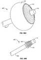
- FIG. 5is a view of an embodiment of an ablative device with a fully circumferential operating radius.
- FIG. 6is a view of an embodiment of an ablative device with a fully circumferential operating radius, with a balloon member in an expanded configuration.
- FIGS. 7A-7Cshow the electrode patterns of the device of FIG. 5 .
- FIGS. 8A-8Dshow electrode patterns that may be used with embodiments of the ablative device with a fully circumferential operating radius, or with any device embodiments described herein.
- FIG. 9is a view of the ablation device of the invention with a partially circumferential operating radius.
- FIG. 10is an end view of the ablation device embodiment of FIG. 9 .
- FIG. 11is an end view of the device of FIG. 9 in an expanded configuration.
- FIGS. 12 , 13 , and 14are end views of the device of FIG. 9 in alternative expanded configurations.
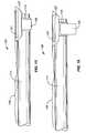
- FIG. 15is a view of the ablation device of the invention in an unexpanded configuration.
- FIG. 16is a view of the ablation device of the invention in an expanded configuration.
- FIGS. 17 and 18are end views of the device in an expanded configuration.
- FIG. 19Ais a view of the ablation device of the invention showing a deflection member feature.
- FIG. 19Bis a view of the ablation device of the invention showing an alternative deflection member wherein the device is in an expanded configuration.
- FIG. 20is a view of device shown in FIG. 19B wherein the deflection member is in an unexpanded configuration.
- FIG. 21is an end view of the device in an unexpanded configuration.
- FIG. 22is an end view of the device shown in FIG. 21 in an expanded configuration.
- FIG. 23is a view of the ablation device of the invention showing a pivoting ablation structure feature.
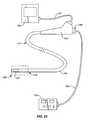
- FIG. 24is an illustration of the ablation device of the invention combined with an endoscope system.
- FIG. 25is a schematic of view of a section through the wall of a representative organ of the bypass-reconstructed gastrointestinal tract, such as a gastric pouch, stoma or tubular portion.
- FIG. 26is a view of the ablation device of the invention including an elongated sheath feature.
- FIG. 27is a view of the device wherein an elongated sheath feature is optically transmissive.
- FIG. 28is an enlarged view of the optically transmissive feature of the device.
- FIG. 29is a cross sectional view of the optically transmissive sheath feature of the device shown in FIGS. 27 and 28 .
- FIG. 30is a view of the device including an alternative optically transmissive sheath feature and an inflation member feature in an expanded configuration.
- FIG. 31is an illustration of the ablation device of FIG. 30 positioned within an esophagus.
- FIG. 32is a view of the ablation device of the invention including a slit sheath feature.
- FIG. 33Ais an end view of a slit sheath feature of the device wherein the sheath is in an unexpanded configuration.
- FIG. 33Bis an end view of a slit sheath feature of the device and an endoscope wherein the sheath is in an expanded configuration.
- FIG. 34Ais a cross sectional view of the device positioned within an endoscope internal working channel wherein an inflatable member feature is in an unexpanded position.
- FIG. 34Bis a view of the device shown in FIG. 34A wherein the inflatable member feature is in an expanded position.
- FIG. 35Ais a cross sectional view of the device positioned within an endoscope internal working channel wherein an expandable member feature is in an unexpanded position.
- FIG. 35Bis a view of the device shown in FIG. 35A wherein the expandable member feature is in an expanded position.
- FIG. 36Ais a cross sectional view of the device positioned within an endoscope internal working channel wherein an alternative expandable member feature is in an unexpanded position.
- FIG. 36Bis a view of the device shown in FIG. 36A wherein the expandable member feature is in an expanded position.
- FIG. 37is a view of the ablation device of the invention including an alternative deflection member.
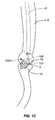
- FIG. 38is an illustration of the ablation device of the invention including an alternative deflection member positioned within the lumen of an organ of the bypass-reconstructed gastrointestinal tract in a non-deflected position.
- FIG. 39is an illustration of the device shown in FIG. 38 wherein the deflection member is in a deflected position.
- FIG. 40is a cross sectional view of the ablation device of the invention showing an internal coupling mechanism feature.
- FIG. 41is a cross sectional view of the ablation device of the invention showing an alternative internal coupling mechanism and a rolled sheath feature.
- FIG. 42is an illustration showing a cross sectional view of the ablation device of the invention positioned within the lumen of an organ of the bypass-reconstructed gastrointestinal tract.
- FIG. 43is an illustration of the ablation device of the invention positioned within an esophagus showing a rotational feature.
- FIG. 44is an illustration of the ablation device of the invention positioned within an esophagus showing a rotational feature combined with an inflation member in an expanded configuration.
- FIGS. 45A-45Care views of the ablation device of the invention showing alternative rotational features.
- FIG. 46Ais a view of an endoscope.
- FIG. 46Bis a view of the ablation device of the invention including a catheter feature.
- FIG. 46Cis a view of a sheath feature of the device.
- FIG. 47is a view of the ablation device of the invention including the features shown in FIGS. 46A-46C in an assembly.
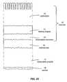
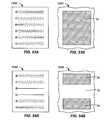
- FIGS. 48A-48Dshow an electrode array with a striped pattern for a fractional ablation and the ablation patterns on tissue that can be made from such a pattern.
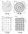
- FIGS. 49A and 49Bshow an electrode array with a concentric-circle pattern for a fractional ablation and the ablation patterns on tissue that can be made from such a pattern.
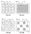
- FIGS. 50A and 50Bshow an electrode array with a checkerboard pattern for a fractional ablation and the ablation patterns on tissue that can be made from such a pattern.
- FIGS. 51A and 51Bshow an electrode array with a checkerboard pattern operating in a non-fractional manner and the ablation pattern on tissue that is made from such an operating pattern.
- FIGS. 52A and 52Bshow an electrode array with a checkerboard pattern operating in a fractional manner and the ablation pattern on tissue that is made from such an operating pattern.
- FIGS. 53A and 53Bshow an electrode array with a striped pattern of alternating positive and negative electrodes operating in a non-fractional manner and the ablation patterns on tissue that can be made from such an operating pattern.
- FIGS. 54A and 54Bshow an electrode array with a striped pattern of alternating positive and negative electrodes operating in a fractional manner and the ablation patterns on tissue that can be made from such an operating pattern.
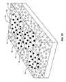
- FIG. 55shows a schematic rendering of a three-dimensional view of a target region of a radial portion of a bypass-reconstructed gastrointestinal wall after it has been ablationally treated.
- FIG. 56A and 56Bprovide views of an ablational device (similar to the devices of FIGS. 38 and 39 ) but including an ablational surface on a hinge structure or deflecting mechanism similar to that depicted in FIG. 43 , the hinge allowing a free pivoting movement of the ablational surface between its longitudinal axis and the longitudinal axis of an endoscope.
- FIG. 56Ashows the device with the ablational surface oriented in parallel with the endoscope.
- FIG. 56Bshows the device with the longitudinal axis of the ablational surface oriented at about a right angle with respect to the longitudinal axis of the endoscope.
- FIG. 57A-57Dprovide perspective views of an ablation device with a 360 degree circumferential ablation surface on an overlapping electrode support furled around an expandable balloon, the operative element including a balloon and an electrode support in an expanded state.
- FIG. 57Ashows the support pulled away from the balloon to clarify that a portion of the support and an edge is adherent to the balloon, and another portion and its edge is not connected to the balloon.
- FIG. 57Bshows the operative element of the device with the non-adherent portion of the support furled around the balloon in a deployable configuration, the non-adherent portion and its edge overlapping around the adherent portion.
- FIG. 57Cshows the device of FIGS. 57A and 57B with an optional feature of the operative element, one or more elastic bands wrapped around the electrode support.
- FIG. 57Dshows the device of FIG. 57C in a collapsed state, with balloon portion being uninflated (or deflated), this being the state of the device when it is being deployed into a lumen and being positioned at a target site, as well as the state of the device after delivering ablation energy and about to be removed from the lumen.
- FIGS. 58A-58Bdepict an embodiment of an ablation device that is adapted to present an ablational surface into a concave or inwardly tapered target site such as the pylorus.
- the deviceincludes an ablational surface circumferentially arranged on the distal portion of an expandable member, the expandable member mounted around the distal end of an endoscope.
- FIG. 58Ashows the device in a deployed configuration.
- FIG. 58Bshows the device with the expandable member in an unexpanded or collapsed state, as would be appropriate for deployment of the device to a target tapered surface, or as would be appropriate for removal from the ablational site.
- U.S. patent application Ser. No. 12/114628 of Kelly et al.provides methods and systems for the use of ablation at various sites in the gastrointestinal tract as a primary therapy for diabetes and morbid obesity.
- the present applicationprovides methods and systems for ablation as a secondary, a rescue, or a salvaging therapy in the wake of a failed surgical approach to obesity such as may occur in Roux-en-Y gastric bypass, biliopancreatic diversion, and sleeve gastrectomy procedures.
- Each of these proceduresreconstructs gastrointestinal tract structure to create new features, by variously creating, for example, a gastric pouch, a stoma, such as a gastrojejunal stoma, or a gastric sleeve that restrict and/or divert the digestive flow.
- a gastric pouchsuch as a gastrojejunal stoma
- a gastric sleevethat restrict and/or divert the digestive flow.
- These new or altered or reconstructed features of bariatric surgerymay also be generally referred to as bypass-reconstructed portion of a gastrointestinal tract.
- Ablation, particularly well-controlled ablation, as provided herein,can have any one or more of several effects that can restore or implement effectiveness of the surgical anatomy in achieving additional weight loss, such as by stricturing or tightening of a lumen or stoma, diminishing compliance, or dampening peristaltic motility.
- Some bariatric proceduressuch as a sleeve gastrectomy, form new structures that have an extended site of suturing or stapling that represent sites of weakness or vulnerability. These sites, in particular, can benefit from therapeutic ablation that creates a healing or scarring response that tightens the treated area and prevents further stretching.
- the objectis to ablate a layer or population of cells that resides in the mucosal layer, but not to disturb the overall size or compliance of the esophagus, which would damage functionality of the organ and be harmful to the patient.
- reduction of lumen volume, and diminished stretchability of the luminal siteis desirable.
- One embodiment or the methodis to repeat ablation treatments so as to create areas of overlap, such overlapping areas having a particularly effective result in terms of creating luminal stricture and reducing the ability of the lumen to expand.
- Longitudinally overlapping treatment sitescan creates undulating or corrugated-like areas along the length of the surgically formed or altered organ where stricture or non-compliant stiffness is particularly pronounced.
- the creation of such areas of particular striction and non-compliancemay provide overall benefit to the patient in terms of achieving the desired weight-loss effect.
- ablation devicesare provided herein, which may be described as having an ablational surface that spans either a 360-degree circumference, or some fractional portion of a full circumference around the device. For example, some devices have an ablational surface that spans about 180 degrees, and others have an ablational surface that spans about 90 degrees.
- ablation devicesto create ablational effects that are directed toward restoring or improving the effectiveness of bariatric surgical results will be described in depicted below in detail.
- FIGS. 1A-1Dprovide a view of a portion of a gastrointestinal tract that has been reconstructed by either a Roux-en-Y bypass procedure (RGB) or a biliopancreatic diversion (BPD); the view includes the esophagus, then proceeding distally, the gastroesophageal junction, a gastric pouch 7 A, a stoma or anastomosis 8 between the gastric pouch and a portion of the small bowel, and a portion of the small bowel itself.
- RGBRoux-en-Y bypass procedure
- BPDbiliopancreatic diversion
- an ablation device of one of two types100 A (with an ablational surface of 360 degrees) or 100 B (with an ablational surface of less than 360 degrees, such as the approximate 90 degree embodiment shown) is supported on an ablation catheter 41 .
- the ablation device( 100 A or 100 B) includes an ablation structure 101 .
- the ablation devicetypically includes an array of electrodes depicted in further detail in other figures, and an inflation member or balloon 105 .
- FIG. 1Ashows an ablative device 100 A with a fully circumferential operating radius inserted into the gastric pouch, filling the lumen of the pouch.
- the ablative deviceis supported on the distal end of an elongated shaft 41 of an instrument, has been inserted into the alimentary tract by an oral or nasal entry route, and has been moved into the proximity of an area targeted for treatment.
- FIG. 1Ashows the ablative device having entered the bypass-reconstructed gastrointestinal tract orally, having entered the gastric pouch 7 A through the esophagus 6 .
- the device depictedis merely an exemplary illustration, and alternative devices are included as embodiments, however what these embodiments have in common is an ablational surface that spans a complete 360 degree circumference that is expandable through the use of an expandable member included in the device internal to the ablational surface.
- an ablational surfacethat spans a complete 360 degree circumference that is expandable through the use of an expandable member included in the device internal to the ablational surface.
- FIGS. 6 , 57 , and 58Several such representative embodiments are shown and further described below ( FIGS. 6 , 57 , and 58 ) and described further below.
- Embodiments of the fully circumferential ablational surfaceare typically cylindrical in form, but embodiments can include circumferential ablational surfaces arranged on surfaces that depart from strict cylindrical, and become more ovalular or spherical, as shown in FIGS. 58A and 58B , with one or both of the (proximal or distal) ends being tapered.
- the ablational surfaceincludes ablational delivery elements such as non-penetrating radiofrequency electrodes, but other types of ablational energy elements are includes as embodiments as well, and as described further below. Exemplary arrangements of radiofrequency electrodes are shown in FIG. 5 , and 7 - 9 . Arrangements of energy delivery elements that create a fractional or partial ablation within a target area, as well as the ablation patterns they deliver to target tissue, are described further below, and depicted in FIGS. 48-55 .
- ablation patternis on a surface that may be pressed into therapeutic contact by an expandable member
- immediate surface upon which the energy delivery elements are arrangedis substantially non-distensible, thus the density of elements across the surface remains constant.
- FIG. 1Bshows an ablative device 100 B with a partially circumferential operating radius inserted into the gastric pouch 7 A, and positioned against a portion of the wall.
- the device depictedis merely an exemplary illustration, and alternative devices are included as embodiments. Described below, and depicted in FIGS. 9-23 , 26 - 47 , and 56 are a number of embodiments that provide an ablational surface of less than a fully circumferential span. In terms of the circumference with respect to the device itself, some embodiments provide an ablational surface of about 90 degrees, some embodiments provide an ablational surface of about 180 degrees, however embodiments include any partially-circumferential span. As described above in the context of the fully circumferentially-ablating device of FIG.
- ablational energy elementsinclude radiofrequency electrodes, among others, and may be arranged on the surface in any pattern, including fractionally-ablating patterns.
- the radial portion of a bypass reconstructed gastrointestinal lumen site(such as a gastric pouch 7 A, a stoma 5 , or a gastric sleeve 7 B) that can be ablationally treated in any single transmission of radiant energy depends on the width of the electrode-covered ablational surface of the embodiment of the device, and the width or diameter of the luminal organ where the treatment site is located.
- the width of embodiments of the ablational surfacein absolute terms, is described in detail below.
- the arc of a curved treatment areacan be anything less than 360 degrees, however it is typically less than 180 degrees, and more particularly may include a smaller radial expanse such as arcs of about 5 degrees, about 10 degrees, about 15 degrees, about 30 degrees, about 45 degrees, about 60 degrees, and about 90 degrees.
- FIG. 1Cshows an ablative device 100 A with a fully circumferential operating radius inserted into the stoma 5 , filling the lumen of the stoma; and
- FIG. 1Dshows an ablative device 100 B with a partially-circumferential operating radius inserted into the stoma and positioned against a portion of the stomal wall 5 .
- FIGS. 2A-2Bprovide a view of a portion of a gastrointestinal tract that has been reconstructed by a sleeve gastrectomy.
- the esophagus and gastroesophageal junctionare similar to that of the RGB or BPD procedures as seen in FIGS. 1A-1C ; the focus in FIGS. 2A and 2B , however, is on the gastric sleeve 7 B formed by suturing or stapling a tubular portion from the stomach, leaving sutured line or remnant 8 , thereby removing the majority of the stomach from the digestive flow path for.
- FIG. 2Ashows an ablative device 100 A with a fully circumferential operating radius inserted into the gastric sleeve 7 B, filling the lumen of the sleeve.
- FIG. 2Bshows an ablative device 100 B with a partially circumferential operating radius inserted into the gastric sleeve 7 B, and positioned against a portion of the wall of the sleeve in the proximity of the remnant suture line 8 .
- the label 100may generally be used to designate ablational devices, regardless of whether their ablational surface 101 is fully circumferential or partially circumferential.
- Metabolic conditionssuch as obesity, diabetes mellitus type 2 , and metabolic syndrome can become such a threat to the health of the patient that medical intervention beyond diets and life-style recommendations are indicated.
- One first line interventional approachis that of bariatric surgery, while another first-line interventional, as described in U.S. patent application Ser. No. 12/114,628 of Kelly et al., filed May 2, 2008 is that of ablational therapy applied to specific sites in the gastrointestinal tract.
- the results of gastric bypass proceduresinclude a significant level of ultimate failure mixed into a prevailing level of general success.
- the applicability of therapeutic methodsFIGS.
- ablationmay be included as a secondary form of intervention in the event of bypass failure, such ablation being directed to specific sites within the surgically formed or surgically-altered structures within the gastrointestinal tract.
- Appropriate information to be evaluatedmay include, for example, the age of the patient, the basal metabolic index, laboratory data on levels of metabolic hormones such as, merely by way of example, any of insulin, glucagon, glucagon-like peptides, insulin-like growth factors, and ghrelin, as well as data on blood glucose levels and glucose tolerance tests.
- metabolic hormonessuch as, merely by way of example, any of insulin, glucagon, glucagon-like peptides, insulin-like growth factors, and ghrelin
- a preliminary endoscopic examination of the features of a bypass-reconstructed alimentary canalmay be appropriate so that any patient-specific features may be mapped out, as well as an evaluation of the general dimensions of the patient's alimentary canal, particularly the newly formed bypass structures.
- Such informationmay be obtained by direct visual observation by endoscopic approaches with optional use of mucosal in-situ staining agents, and may further be accomplished by other diagnostic methods, including non-invasive penetrative imaging approaches such as narrow band imaging from an endoscope.
- evaluation of a siteincludes identifying the locale of the site, including its dimensions.
- evaluation of target tissueincludes identifying a multiplicity of sites, if there is more than one site, and further identifying their locale and their respective dimensions.
- evaluating target sitesmay include identifying or grading any pathology or injury or specific site of failure within the bypass-reconstructed gastrointestinal tract, particularly identifying any areas of clinical significance or concern that are overlapping or near the areas to be targeted for ablation.
- features of a gastrointestinal tract that has been subjected to bariatric surgery, and which has subsequently been found to be functionally unsuccessful in terms of the patient achieving loss of excess weightwill be dilated or distended, and show signs of being overly compliant, i.e., too easily stretched.
- bypass-reconstructed gastrointestinal target tissuemay be treated with embodiments of an inventive ablational device and associated methods as described herein.
- Evaluation of the status of target tissue sites for ablationmay also be advantageously implemented as part of an ablational therapy method ( FIG. 3 ), as for example, in close concert with the ablation, either immediately before the application of ablational energy (such as radiant energy), and/or immediately thereafter.
- the treatment sitecan be evaluated by any diagnostic or visual method at some clinically appropriate time after the ablation treatment, as for example a few days, several weeks, or several few months, or at anytime when clinically indicated following ablational therapy. In the event that any follow-up evaluation shows either that the therapy was unsatisfactorily complete, or that there is a recovery in the population of cells targeted for ablation, a repetition of the ablational therapy may be indicated.
- ablational deviceshave an ablational structure arrayed with energy-transmitting elements such as electrodes.
- the devicesmay be mounted on, or supported by any appropriate instrument that allows movement of the ablational surface to the local of a target site.
- Such instrumentsare adapted in form and dimension to be appropriate for reaching the target tissue site, and may include simple catheters adapted for the purpose;
- some embodiments of the insertive instrumentinclude endoscopes that, in addition to their supportive role, also provide a visualization capability.
- an endoscope separate from the supportive instrumentmay participate in the ablational procedure by providing visual information.
- Exemplary embodiments of the inventive device as described hereintypically make use of electrodes to transmit radiofrequency energy, but this form of energy transmission is non-limiting, as other forms of energy, and other forms of energy-transmission hardware are included as embodiments of the invention.
- Ablational energymay include, by way of example, microwave energy emanating from an antenna, light energy emanating from photonic elements, thermal energy transmitted conductively from heated ablational structure surfaces or as conveyed directly to tissue by heated gas or liquid, or a heat-sink draw of energy, as provided by cryonic or cryogenic cooling of ablational structure surfaces, or as applied by direct contact of cold gas or fluid with tissue, or by heat-draw through a wall of a device that separates the cold gas or fluid from the tissue.
- Embodiments of the ablational deviceinclude variations with regard to the circumferential expanse of the ablational surface to be treated, some embodiments provide a fully circumferential ablation surface and others provide a surface that is less than fully circumferential, as described above. Choosing the appropriate device is a step included within the therapeutic method provided, as shown in FIG. 3 . These and other variation may provide particular advantages depending on the nature, extent, locale, and dimensions of the one or more targeted tissue sites on the wall the alimentary canal.
- One embodiment of the inventionincludes a device with an ablational surface that is fully circumferential, i.e., encompassing a radius of 360 degrees, such that a full radial zone within a luminal organ is subject to ablation.
- ablationmay be implemented to a varying degree, depending on the energy output and the pattern of the ablational elements (such as electrodes), but with substantial uniformity within the zone of ablation.
- This embodimentmay be particularly appropriate for treating widespread or diffuse sites within a bypass-reconstructed gastrointestinal tract organ.
- the ablational surface of the inventive deviceis partially circumferential, such that it engages a fraction of the full internal perimeter or circumference of a luminal organ.
- the fractional portion of the circumference ablated on the inner surface of a luminal organdepends on the size of the luminal organ being treated (radius, diameter, or circumference) and on the dimensions of the ablational surface, as detailed further below.
- the smaller or more discrete ablational surfaceprovided by this latter embodiment may be advantageous.
- This type of operational control of a circumferential subset of ablation energy elements around a 360-degree circumferential arrayis analogous to the fractional operation of a patterned subset of an electrode array, as described below in the section titled “Electrode patterns and control of ablation patterns across the surface area of tissue”.
- a particular arc of the arrayis activated to deliver energy to an arc of the circumference.
- energyis delivery to a portion of the tissue in the target area, while another portion receives insufficient energy to achieve ablation.
- these operational variationscan be combined, that is, a patterned subset of a circumferential arc can be activated.
- FIGS. 3 and 4together provide flow diagram depictions of embodiments of the method for ablating tissue in the wall of the alimentary canal that has been reconstructed by a bariatric procedure, and has subsequently failed or been demonstrably ineffective.
- the diagramsrepresent common aspects of the embodiments of the method, as delivered by two embodiments of the device, one which has a 360 degree circumferential ablation structure, and one which has an ablation structure comprising an arc of less than 360 degrees.
- FIG. 3is a flow diagram depicting an overview of the method with a focus on patient evaluation and determination of a clinically appropriate site within the alimentary canal for ablational treatment.
- a responsible clinicianmakes an informed choice with regard to the appropriate embodiment with which to treat the patient, i.e., either a device with the 360 degree electrode array 10 A, or a device 100 B with the electrodes arrayed in an arc of less than 360 degrees.
- another treatment choicemay be made between operating the electrodes throughout the 360 degree circumference, or whether to operate a radial subset of the electrode array.
- a clinicianfurther considers and makes a determination as to the protocol for ablation, considering the amount of energy to be delivered, the energy density, the duration of time over which energy is to be delivered. These considerations take into the account the surface area to be ablated, the depth of tissue which is to be treated, and the features of the electrode array, whether, for example, it is to be a fractional electrode, and which pattern may be desirable.
- another preliminary step to operating the methodmay include a closer evaluation of the target tissue site(s) within the alimentary canal. Evaluation of the site may include the performance of any visualization or diagnostic method that provides a detailed census of the number of discrete target tissue sites, their dimensions, their precise locations, and/or their clinical status, whether apparently normal or abnormal.
- This stepis shown following the choice of instrument, but may occur simply in conjunction with diagnosis, or at any point after diagnosis and general localization of the target tissue.
- an evaluating stepis typically performed prior to ablation, as outlined in the operational steps of the method, as shown in the flow diagram of FIG. 4 .
- FIG. 4is a flow diagram depicting the method after the target site within the bypass-reconstructed gastrointestinal tract has been localized and a choice has been made regarding the preferred ablational device.
- the methodincludes an evaluation of the site, including particulars of location, stage, determination of the number of sites, and the dimensions, as described above, and using approaches detailed in the references provided in the background, and/or by using whatever further approaches may be known by those practiced in the art.
- the methodcontinues with insertion of the instrument and the movement of the ablational structure to the locale of the target tissue to be ablated. Subsequently, more refined movements of the ablational structure may be performed that create a therapeutically effective contact between the ablational structure and the target tissue site.
- therapeutically effective contactmay be made by inflating a balloon underlying the electrode array.
- the device with an electrode surface spanning an arc of less than 360 degreesmovements that bring the ablational surface into therapeutically effective contact may include any of inflation of a balloon, inflation of a deflection member, and/or movement of a deflection member, all of which are described further below.
- a subsequent stepincludes the emission of ablational energy from the device.
- Variations of ablational energy emissionmay include ablating a single site as well as moving the instrument to a second or to subsequent sites that were identified during the evaluation step.
- a subsequent stepmay include an evaluation of the treated target site; alternatively evaluation of the consequences of ablation may include the gathering of clinical data and observation of the patient.
- an endoscopeis included in the procedure, either as the instrument supporting the ablational structure, or as a separate instrument, such evaluation may occur immediately or very soon after ablation, during the procedure, when instruments are already in place.
- the treated sitemay be evaluated at any clinically appropriate time after the procedure, as for example the following day, or the following week, or many months thereafter.
- the methodappropriately includes a repetition of the steps just described and schematically depicted in FIG. 4 .
- evaluation of the consequences of ablationmay include the gathering of a complete spectrum of clinical and metabolic data from the patient. Such information includes any test that delivers information relevant to the metabolic status of the patient such as the information gathered when determining the appropriateness of ablational intervention, as was made in the first step of FIG. 3 .
- evaluation of the effectiveness of the bariatric effectiveness of the ablation methodmay include any of a panoply of metabolic tests such as described in detail in U.S. patent application Ser. No. 12/114,628 of Kelly et al. entitled “Method and apparatus for gastrointestinal tract ablation for treatment of obesity”, as filed on filed May 2, 2008.
- Methods for accomplishing ablation of targeted cells within the bypass-reconstructed gastrointestinal tractinclude the emission of radiant energy at conventional levels to accomplish ablation of epithelial and with or without deeper levels of tissue injury, more particularly to remove or functionally compromise cells that are involved in the sensation of satiety or the regulation of metabolic hormones such as insulin.
- an elongated flexible shaft 41is provided for insertion into the body in any of various ways selected by a medical care provider.
- the shaftmay be placed endoscopically, e.g. passing through the mouth and esophagus and then further into the bypass-reconstructed gastrointestinal tract, or it may be placed surgically, or by any other suitable approach.
- radiant energy distribution elements or electrodes on an ablation structure 101are provided at a distal end of the flexible shaft 41 to provide appropriate energy for ablation as desired.
- the radiant energy distribution elementsare configured circumferentially around 360 degrees.
- alternative energy sourcescan be used with the ablation structure to achieve tissue ablation and may not require electrodes.
- Such energy sourcesinclude: ultraviolet light, microwave energy, ultrasound energy, thermal energy transmitted from a heated fluid medium, thermal energy transmitted from heated element(s), heated gas such as steam heating the ablation structure or directly heating the tissue through steam-tissue contact, light energy either collimated or non-collimated, cryogenic energy transmitted by cooled fluid or gas in or about the ablation structure or directly cooling the tissue through cryogenic fluid/gas-tissue contact.
- heated gassuch as steam heating the ablation structure or directly heating the tissue through steam-tissue contact
- cryogenic energy transmitted by cooled fluid or gas in or about the ablation structure or directly cooling the tissue through cryogenic fluid/gas-tissue contactEmbodiments of the system and method that make use of these aforementioned forms of ablational energy include modifications such that structures, control systems, power supply systems, and all other ancillary supportive systems and methods are appropriate for the type of ablational energy being delivered.
- the flexible shaftcomprises a cable surrounded by an electrical insulation layer and comprises a radiant energy distribution elements located at its distal end.
- a positioning and distending device around the distal end of the instrumentis of sufficient size to contact and expand the walls of the bypass-reconstructed gastrointestinal tract lumen or organ in which it is placed (e.g. the gastric pouch, the stoma, or the gastric sleeve) both in the front of the energy distribution elements as well as on the sides of the energy distribution elements.
- the distal head of the instrumentcan be supported at a controlled distance from the wall of the bypass-reconstructed gastrointestinal tract lumen or organ by an expandable balloon or inflation member, such that a therapeutically-effective contact is made between the ablation structure and the target site so as to allow regulation and control the amount of energy transferred to the target tissue within the lumen when energy is applied through the electrodes.
- the balloonis preferably bonded to a portion of the flexible shaft at a point spaced from the distal head elements.
- a fully-circumferential ablation deviceinclude a distendible or expandable balloon member as the vehicle to deliver the ablation energy.
- One feature of this embodimentincludes means by which the energy is transferred from the distal head portion of the invention to the membrane comprising the balloon member.
- one type of energy distributionthat may be appropriate and is incorporated herein in its entirety is shown in U.S. Pat. No. 5,713,942, in which an expandable balloon is connected to a power source that provides radio frequency power having the desired characteristics to selectively heat the target tissue to a desired temperature.
- a balloon per embodiments of the current inventionmay be constructed of an electroconductive elastomer such as a mixture of polymer, elastomer, and electroconductive particles, or it may comprise a nonextensible bladder having a shape and a size in its fully expanded form which will extend in an appropriate way to the tissue to be contacted.
- an electroconductive membermay be formed from an electroconductive elastomer wherein an electroconductive material such as copper is deposited onto a surface and an electrode pattern is etched into the material and then the electroconductive member is attached to the outer surface of the balloon member.
- the electroconductive membere.g.
- the balloon member 105has a configuration expandable in the shape to conform to the dimensions of the expanded (not collapsed) inner lumen of the human lower bypass-reconstructed gastrointestinal tract.
- electroconductive membermay consist of a plurality of electrode segments arrayed on an ablation structure 101 having one or more thermistor elements associated with each electrode segment by which the temperature from each of a plurality of segments is monitored and controlled by feedback arrangement.
- the electroconductive membermay have means for permitting transmission of microwave energy to the ablation site.
- the distending or expandable balloon membermay have means for carrying or transmitting a heatable fluid within one or more portions of the member so that the thermal energy of the heatable fluid may be used as the ablation energy source.
- a fully circumferential ablation deviceinclude a steerable and directional control means, a means for accurately sensing depth of cautery, and appropriate alternate embodiments so that in the event of a desire not to place the electroconductive elements within the membrane forming the expandable balloon member it is still possible to utilize the balloon member for placement and location control while maintaining the energy discharge means at a location within the volume of the expanded balloon member, such as at a distal energy distribution head.
- Embodiments of the inventioninclude methods whereby an ablation device, such as a fully circumferential ablation device, is used as a method of restoring or rescuing the therapeutic effectiveness of bariatric procedures that have failed or are degrading due to a compromise or unsatisfactory result in a surgically formed gastrointestinal tract feature.
- the surgerycan be understood as an initial therapy that has failed, and the ablation can be understood as a secondary interventional therapy.
- the primary indicationremains, i.e., the metabolic disease, but the ablational therapy is being directed more immediately toward supporting the initial surgical intervention.
- Ablational targetsthus include structures such as a gastric pouch, stomas formed by the procedure, or gastric tubes or sleeves.
- the patientAfter determining that the portion or portions of the bypass-reconstructed gastrointestinal tract wall having this tissue that is targeted either for full or partial ablation, the patient is prepared for a procedure in a manner appropriate according to the embodiment of the device to be utilized. Then, the practitioner inserts into the patient, in one embodiment, the ablation device shown and discussed herein via endoscopic access and control. Further positioning of portions of the device occurs as proper location and visualization identifies the ablation site in the bypass-reconstructed gastrointestinal tract. Selection and activation of the appropriate quadrant(s) or portion(s)/segment(s) on the ablation catheter member is performed by the physician, including appropriate power settings according to the depth of cautery desired.
- Additional settingsmay be necessary as further ablation is required at different locations and/or at different depths within the patient's bypass-reconstructed gastrointestinal tract. Following the ablation, appropriate follow-up procedures as are known in the field are accomplished with the patient during and after removal of the device from the bypass-reconstructed gastrointestinal tract.
- the practitionermay first determine the length of the portion of the bypass-reconstructed gastrointestinal tract requiring ablation and then may choose an ablation catheter from a plurality of ablation catheters of the invention, each catheter having a different length of the electrode member associated with the balloon member. For example, if the practitioner determines that 1 centimeter of the bypass-reconstructed gastrointestinal tract surface required ablation, an ablation catheter having 1 centimeter of the electrode member can be chosen for use in the ablation.
- the length of the electrode member associated with the balloon membercan vary in length, as for example, from 1 to 10 cm.
- a plurality of ablation catheters wherein the radiant energy distribution elements are associated with the balloon membercan be provided wherein the diameter of the balloon member when expanded varies from 12 mm to 40 mm.
- the practitionerwill choose an ablation catheter having a diameter when expanded which will cause the bypass-reconstructed gastrointestinal tract to stretch and the mucosal layer to thin out, thus, reducing or occluding blood flow at the site of the ablation. It is believed that by reducing the blood flow in the area of ablation, the heat generated by the radiant energy is less easily dispersed to other areas of the target tissue thus focusing the energy to the ablation site.
- One approach a practitioner may use to determine the appropriate diameter ablation catheter to use with a particular patientis to use in a first step a highly compliant balloon connected to a pressure sensing mechanism.
- the balloonmay be inserted into a luminal organ within the bypass-reconstructed gastrointestinal tract and positioned at the desired site of the ablation and inflated until an appropriate pressure reading is obtained.
- the diameter of the inflated balloonmay be determined and an ablation device of the invention having a balloon member capable of expanding to that diameter chosen for use in the treatment.
- the pressure to be exerted to do soshould therefore be greater than the pressure exerted by such vessels.
- electronic meansare used for measuring the luminal target area of gastrointestinal features that have been formed by bariatric surgery so that energy may be appropriately normalized for the surface area of the target tissue.
- electronic meansare described in detail in U.S. patent application Ser. No. 12/143,404, of Wallace et al., entitled “Electical means to normalize ablational energy transmission to a luminal tissue surface of varying size”, as filed on Jun. 20, 2008, which is incorporated in entirety.
- An embodiment of a device with a 360 degree ablational surfaceis described in detail in that application, and is depicted in FIGS. 57A-57D of this application.
- Pressure sensing meansmay also be used to measure the size of a lumen in preparation for an ablation treatment, as described in U.S. patent application Ser. No. 11/244,385 of Jackson, published as U.S. 2006/0095032.
- FIGS. 57A-57Dprovide perspective views of an ablation device 100 with an overlapping electrode support 360 furled around an expandable balloon 105 .
- An array of ablational energy delivery elements 101such as radiofrequency electrodes is arranged on the exterior surface of the electrode support.
- FIG. 57Ashows the electrode support 360 pulled away from the balloon 105 to clarify that a portion of the support and an inner edge 362 is adherent to the balloon, and another portion and its outer edge 364 is not connected to the balloon.
- FIG. 57Bshows the non-adherent portion of the electrode support 360 furled around the balloon 105 in a deployable configuration, the non-adherent portion and its edge overlapping around the adherent portion.
- FIG. 57Cshows an optional feature of the device 10 A, one or more elastic bands 380 wrapped around the electrode support 360 .
- the elastic band 380 materialis a conductive elastomer, as described in greater detail below, which can be included in a size-sensing circuit to provide information related to the degree of expansion of the operative element.
- FIG. 57Dshows the device of FIG. 57C in a collapsed state, with balloon portion 105 being uninflated (or deflated), this being the state of the device when it is being deployed into a lumen and being positioned at a target site, as well as the state of the device after delivering ablation energy and about to be removed from the lumen.
- FIGS. 58A-58BAnother embodiment of an ablation device with a fully circumferential ablation surface is provided in FIGS. 58A-58B .
- This particular device embodiment 400is adapted to present an ablational surface 101 into a concave or inwardly tapered target site such as distal portion of the antrum of the stomach, or in the vicinity of the pylorus, which is a site for vascular lesions typical of watermelon stomach.
- the deviceincludes an ablational surface circumferentially arranged on the distal portion of an expandable member 105 , the expandable member mounted around the distal end 110 of the shaft of an endoscope 111 .
- FIG. 58Ashows the device in a deployed configuration.
- FIG. 58Bshows the device with the expandable member in an unexpanded or collapsed state, as would be appropriate for deployment of the device to a target tapered surface, or as would be appropriate for removal from the ablational site.
- FIG. 58Cshows the device of FIG. 58A as it can be deployed into a tapered or concave target site such as the pylorus 9 .
- FIG. 58Dshows the device of FIG. 58A in an alternative configuration, with the electrode bearing surface of the device reversed such that it is facing proximally, and can thus be pulled retrograde into a tapered or concave site such as the lower esophageal sphincter 10 .
- FIGS. 5-7The device used is shown schematically in FIGS. 5-7 .
- the elongated flexible shaft 41 of a device with a fully circumferential ablation surfaceis connected to a multi-pin electrical connector 94 which is connected to the power source and includes a male luer connector 96 for attachment to a fluid source useful in expanding the expandable member.
- the elongated flexible shafthas an electrode 98 wrapped around the circumference.
- the expandable member of the device shown in FIGS. 5 and 6further includes three different electrode patterns, the patterns of which are represented in greater detail in FIGS. 7A-7C .
- the elongated flexible shaft 41comprises six bipolar rings 62 with about 2 mm separation at one end of the shaft (one electrode pattern), adjacent to the bipolar rings is a section of six monopolar bands or rectangles 65 with about 1 mm separation (a second electrode pattern), and another pattern of bipolar axial interlaced finger electrodes 68 is positioned at the other end of the shaft (a third electrode pattern).
- a null space 70is positioned between the last of the monopolar bands and the bipolar axial electrodes.
- the catheter used in the studywas prepared using a polyimide flat sheet of about 1 mil (0.001′′) thickness coated with copper. The desired electrode patterns were then etched into the copper.
- Pattern 80is a pattern of bipolar axial interlaced finger electrodes with about 0.3 mm separation.
- Pattern 84includes monopolar bands with 0.3 mm separation.
- Pattern 88is that of electrodes in a pattern of undulating electrodes with about 0.25 mm separation.
- Pattern 92includes bipolar rings with about 0.3 mm separation.
- the electrodesare attached to the outside surface of a balloon 72 having a diameter of about 18 mm.
- the devicemay be adapted to use radio frequency by attaching wires 74 as shown in FIG. 5 to the electrodes to connect them to the power source.
- the preceding electrode array configurationsare described in the context of an ablation structure with a full 360 degree ablation surface, but such patterns or variants thereof may also be adapted for ablation structures that provide energy delivery across a surface that is less than completely circumferential, in structures, for example, that ablate over any portion of a circumference that is less than 360 degrees, or for example structures that ablate around a radius of about 90 degrees, or about 180 degrees.
- Embodiments of the ablation system provided hereinare generally characterized as having an electrode pattern that is substantially flat on the surface of an ablation support structure and which is non-penetrating of the tissue that it ablates.
- the electrode patternforms a contiguous treatment area that comprises some substantial radial aspect of a luminal organ; this area is distinguished from ablational patterns left by electrical filaments, filament sprays, or single wires.
- the radial portionmay be fully circumferential; the radial portion of a luminal organ that is ablated by embodiments of the invention is function of the combination of (1) the circumference of the organ, which can be relatively large in the case of gastric pouch, and small when in the case of a region in a stoma or a gastric sleeve, and (2) the dimensions of the electrode pattern.
- the radial expanse of a treatment areamay be as large as 360 degrees, and as small as about 5 to 10 degrees, as could be the case in a treatment area within the stomach.
- Embodiments of the ablational energy delivery system and method providedare also characterized by being non-penetrating of the target tissue.
- Ablational radiofrequency energyis delivered from the flat electrode pattern as it makes therapeutic contact with the tissue surface of a treatment area, as described elsewhere in this application; and from this point of surface contact, energy is directly inwardly to underlying tissue layers.
- Some embodiments of the ablational system and method provided hereincan be further characterized by the electrode pattern being configured to achieve a partial or fractional ablations, such that only a portion of the tissue surface receives sufficient radiofrequency energy to achieve ablation and another portion of the surfaces receives insufficient energy to achieve ablation.
- the system and methodcan be further configured to control the delivery of radiofrequency energy inwardly from the tissue surface such that depth of tissue layers to which energy sufficient for ablation is delivered is controlled.
- Controlling the fraction of the tissue surface target area that is ablatedcomes about by having some fraction of the tissue ablated, at least to some degree, and having some fraction of the surface within the target area emerge from the treatment substantially free of ablation.
- the ability to control the ratio of ablated and non-ablated surfacecan provide substantial benefit to the treatment.
- the ablational target areas in this methodafter all, are not cancerous, in which case their complete ablation may be desired, and in fact the target areas may not be abnormal in any sense.
- the ablational treatmentper embodiments of this invention, may directed not necessarily toward correcting any defect of the target tissue, but rather toward a larger therapeutic end, where, in fact, that end is served by creation of a modulated dampening of the normal properties or function of the target area.
- the organ in which the ablation target area is locatedcan be appreciated as a population of particular target cells within the tissue of the target area, which can function, based on their health, at a functional capacity at some low threshold of 20%, for example, when in poor condition, and at 100%, when in optimal condition.
- the object of the ablational treatment provided herein, within this example by analogymay not be to render the full population of cells to be dysfunctional and operating at 50% capacity.
- the object of the treatmentmay be to have some fraction of the cells within the population, post-ablational treatment, to remain fully functional, operating at about 100% capacity, and to have some remaining fraction operating at a range of lower capacity.
- Controlling the fraction of the tissue surface target area that is ablated, per embodiments of the invention,is provided by various exemplary approaches: for example, by (1) the physical configuration of electrode pattern spacing in a comparatively non-dense electrode pattern, and by (2) the fractional operation of a comparatively dense electrode array, in a billboard-like manner.
- creating a fractional ablation by physical configuration of the electrode patternincludes configuring the electrode pattern such that some of the spacing between electrodes is sufficiently close that the conveyance of a given level of energy between the electrodes sufficient to ablate tissue is allowed, and other spacing between electrodes is not sufficiently close enough to allow conveyance of the level of energy sufficient to ablate.
- Embodiments of exemplary electrode patterns that illustrate this approach to creating fractional ablationare described below, and depicted in FIGS. 48-55 .
- the creation of an ablation pattern by activating a subset of electrodesrepresents an operation of the inventive system and method which is similar to the described above, wherein an ablational structure with a fully circumferential pattern of electrodes can be operated in a manner such that only a radial fraction of the electrodes are operated.
- the ablation system of the inventionincludes an electrode pattern with a plurality of electrodes and a longitudinal support member supporting the electrode pattern, as described in numerous embodiments herein.
- Energyis delivered to the electrodes from a generator, and the operation of the generator is controlled by a computer-controller in communication with the generator, the computer controller controlling the operating parameters of the electrodes.
- the computer controllerhas the capability of directing the generator to deliver energy to all the electrodes or to a subset of the electrodes.
- the controllerfurther has the ability to control the timing of energy delivery such that electrodes may be activated simultaneously, or in subsets, non-simultaneously.
- the electrodesmay be operated in a monopolar mode, in a bipolar mode, or in a multiplexing mode.
- creating a fractional ablation by an operational approach with a comparatively dense electrode arrayincludes operating the electrode pattern such that the energy delivered between some of the electrodes is sufficient to ablate, whereas energy sufficient to ablate is not delivered between some of the electrodes.
- Embodiments of exemplary electrode patterns that illustrate this approach to creating fractional ablationare described below, and depicted in FIGS. 48-55 .
- Another aspect of controlling the fraction of tissue ablationrelates to controlling the depth of ablation into tissue layers within the target area.
- Energyis delivered inwardly from the surface, thus with modulated increases in energy delivery, the level of ablation can be controlled such that, for example, the ablated tissue may consist only of tissue in the epithelial layer, or it may consist of tissue in the epithelial layer and the lamina basement layers, or it may consist of tissue in the epithelial, lamina basement and muscularis mucosal layers, or it may consist of tissue in the epithelial, lamina basement, muscularis mucosa, and submucosal layers, or it may consist of tissue in the epithelial layer, the lamina limbal, the muscleis mucosae, the submucosa, and the muscularis propria layers.
- ablational energynot delivered to the serosal layer of the bypass-reconstructed gastrointestinal tract.
- Embodiments of the inventioninclude RF electrode array patterns that ablate a fraction of tissue within a given single ablational area, exemplary fractional arrays are shown in FIGS. 48A , 49 A, and 50 A. These fractional ablation electrode arrays may be applied, as above, to above to ablational structures that address a fully circumferential target area, or a structure that addresses any portion of a full circumference such as 90 degree radial surface, or a 180 degree radial surface.
- FIG. 48Ashows a pattern 180 of linear electrodes 60 aligned in parallel as stripes on a support surface.
- the electrodesare spaced apart sufficiently such that when pressed against tissue in therapeutic contact, the burn left by distribution of energy through the electrodes results in a striped pattern 190 on the target tissue as seen in FIG. 48B corresponding to the electrode pattern, with there being stripes of burned or ablated tissue 3 a that alternate with stripes of unburned, or substantially unaffected tissue 3 b .
- the ablationmay be repeated with the ablational structure positioned at a different angle.
- FIG. 48Cdepicts a tissue burn pattern 191 created by a first ablational event followed by a second ablational event after the ablational structure is laterally rotated by about 90 degrees.
- FIG. 48Ddepicts a tissue burn pattern 192 created by a first ablational event followed by a second ablational event after the ablational structure is laterally rotated by about 45 degrees.
- the effect of an ability to ablate a tissue surface in this manneradds another level of fine control over tissue ablation, beyond such parameters as total energy distributed, and depth of tissue ablation.
- the level of control provided by fractional ablation, and especially when coupled with repeat ablational events as described above in FIGS. 48C and 48Dis to modulate the surface area-distributed fraction of tissue that is ablated to whatever degree the local maximal ablation level may be.
- the fractional ablation provided by such fractional electrode patternmay be particularly advantageous when the effects of ablation are not intended to be absolute or complete, but instead a functional compromise of tissue, or of cells within the tissue is desired.
- a desirable resultcould be a partial reduction in overall function of a target area, rather than a total loss of overall function.
- Another example where such fractional ablation may be desirableis in the case where ablation is intended to be temporary or transient.
- a desirable resultmay be the transient compromise of tissue during which time the effect of such compromise may be evaluated.
- an ablation patternthat includes a burned area 3 a and an unburned area 3 b , it can be understood that cells from the unburned area could give rise to cells that would migrate or repopulate the denuded area within the burned area 3 b.
- FIGS. 49A and 50Adepict other examples of a fractionally-ablating electrode pattern on an ablation structure
- FIGS. 49B and 50Bshow the respective fractional burn patterns on tissue that have been treated with these electrode patterns.
- a pattern of concentric circles 182is formed by wire electrodes that (from the center and moving outward) form a + ⁇ ⁇ + + ⁇ pattern.
- the tissue between + ⁇ electrodesis burned, and the tissue between ++ electrode pairs or ⁇ ⁇ electrode pairs is not burned.
- the concentric pattern 192 of FIG. 49Bis formed.
- Embodiments of fractionally-ablating electrode patterns such as those in FIG. 49Aneed not include perfect circles, and the circles (imperfect circles or ovals) need not be perfectly concentric around a common center.
- FIG. 50Ashows a checkerboard pattern 184 of + and ⁇ electrodes which when activated create a burn pattern 194 as seen in FIG. 50B .
- Tissue that lies between adjacent + and ⁇ electrodesis burned, while tissue that lies between adjacent + + electrodes or ⁇ ⁇ electrode pairs remains unburned.
- FIG. 50Bincludes a representation of the location of the + and ⁇ electrodes from the ablation structure in order to clarify the relative positions of areas that are burned 3 a and the areas that remain substantially unburned 3 b.
- Embodiments of the inventioninclude RF electrode array patterns that ablate a fraction of tissue within a given single ablational area by virtue of operational approaches, whereby some electrodes of a pattern are activated, and some are not, during an ablational event visited upon a target area.
- Exemplary fractional arraysare shown in FIGS. 51A , 52 A, 53 A and 54 A. These fractional ablation electrode arrays may be applied, as above, to ablational structures that address a fully circumferential target area, or a structure that addresses any portion of a full circumference such as, by way of example, a 90 degree radial surface, or a 180 degree radial surface.
- FIG. 51Ashows a checkerboard electrode pattern during an ablational event during which all electrode squares of the operational pattern 186 A are operating, as depicted by the sparkle lines surrounding each electrode. Operating the electrode pattern 186 A in this manner produces an ablation pattern 196 A, as seen in FIG. 51B , wherein the entire surface of tissue within the treatment area is ablated tissue 3 a .
- FIG. 52Ashows a checkerboard electrode pattern during an ablational event during which only every-other electrode square of the operational pattern 186 B is operating, as depicted by the sparkle lines surrounding each activated electrode. Operating the electrode pattern 186 B in this manner produces an ablation pattern 196 B, as seen in FIG. 52B , wherein a checkerboard fractionally ablated pattern with a dispersed pattern of ablated squares 3 a of tissue 3 a alternate with square areas of tissue 3 b that are not ablated.
- FIG. 53Ashows a striped linear electrode pattern of alternating + and ⁇ electrodes during an ablational event during which all electrode squares of the operational pattern 188 A are operating, as depicted by the sparkle lines surrounding each linear electrode. Operating the electrode pattern in this manner 188 A produces an ablation pattern 198 A, as seen in FIG. 53B , wherein the entire surface of tissue within the treatment area is ablated tissue 3 a.
- FIG. 54Ashows a striped linear electrode pattern 188 B of alternating + and ⁇ electrodes during an ablational event during which alternate pairs of the linear electrode pairs are operating, as depicted by the sparkle lines surrounding the activated linear electrodes.
- Operating the electrode pattern in this manner 188 Bproduces an ablation pattern 198 B, as seen in FIG. 54B , wherein stripes of ablated tissue 3 a within the treatment area alternate stripes of non-ablated tissue 3 b.
- FIG. 55is a schematic rendering of a three dimensional view of a target region of a radial portion of a bypass-reconstructed gastrointestinal wall after it has been ablationally treated, per embodiments of the invention.
- Ablated regions 3 aare rendered as regions distributed through the target area within a larger sea of non-ablated tissue 3 b . These regions are depicted as being slightly conical in this schematic view, but in practice the ablated tissue region may be more cylindrical in shape.
- the regions 3 aare of approximately the same depth, because of the control exerted over the depth of the ablation area into layers of the gastrointestinal wall, as described herein. With such control, the regions 3 a can vary with respect of the layer to which they extend continuously from the upper surface where ablational energy has been applied.
- the conical regionsare of approximately the same width or diameter, and distributed evenly throughout the tissue, because of the control over ablational surface area, as described herein.
- the therapeutic targetis actually a particular type of cell 4 b (open irregular spheres), for example, a nerve cell, or endocrine secretory cell; and these cells are distributed throughout the target area.
- the post-ablation therapeutic target cells 4 aare those which happened to be included within the conical regions 3 a that were ablated.
- the post-ablation cells 4 amay be rendered dysfunctional to varying degree, they may be completely dysfunctional, they may be, merely by way of illustrative example, on the average, 50% functional by some measure, and there functionality may vary over a particular range. It should be particularly appreciated however, per embodiments of the invention, that the cells 4 b , those not included in the ablated tissue cones, are fully functional.
- ablationcan be controlled with regard to the depth of the ablation below the level of the tissue surface where the ablative structure makes therapeutic contact with the tissue.
- the energy delivery parameters appropriate for delivering ablation that is controlled with regard to depth in tissuemay be determined experimentally.
- an experimental set of exerciseswas performed on normal immature swine in order to understand the relationship between the electrical parameters of electrode activation and the resultant level of ablation in esophageal tissue. The data are shown in detail in U.S. application Ser. No. 10/370,645 of Ganz et al, filed on Feb.
- Such parameters as applied by ablational electrode patterns on an ablational structure with a 360 degree operating surface that is directed to esophageal tissueinclude 300W delivered within 300 msec, with a tightly spaced with tightly spaced bi-polar electrode array (less than 250 microns). Ablation depth related to the energy density delivered with 8-12 J/cm2 results in complete removal of the epithelium.
- Such parameters as applied by electrode patterns on an ablation structure with an operating radial surface of about 90 degreesincludes multiple narrow band electrodes spaced 250 microns wide, where the generator delivers very high power energy density at 40 W/cms to the tissue in an energy dosage of 12-15 J/cm2.
- depth variancescan be achieved via time of ablation, dosage, number of energy applications, and electrode spacing.
- FIG. 25provides a schematic representation of the histology of the bypass-reconstructed gastrointestinal wall as it is found in various luminal organs such as the esophagus, stomach, pylorus, duodenum, and jejunum.
- the relative presence and depth and composition of the layers depicted in FIG. 25vary from organ to organ, but the basic organization is similar.
- the layers of the bypass-reconstructed gastrointestinal wallwill be described in their order from the innermost to the outermost layer facing the bypass-reconstructed gastrointestinal lumen; and as seen FIG. 25 and in terms of the direction from which an ablational structure would approach the tissue.
- the innermost layercan be referred to as the surface (epithelium), and succeeding layers can be understood as being below or beneath the “upper” layers.
- the innermost layer of a bypass-reconstructed gastrointestinal tract organ, which is in direct contact with the nutrients and processed nutrients as they move through the gutis a layer of epithelium 12 .
- This layersecretes mucous which protects the lumen from abrasion and against the corrosive effect of an acidic environment.
- Beneath the epitheliumis a layer known as the lamina basement 13 , and beneath that, a layer known as the muscularis mucosae 14 .
- the epithelium 12 , the lamina limbalium 14collectively constitute the mucosa 15 .
- the muscularis propria 17includes various distinct layers of smooth muscle that enwrap the organ, in various orientations, including oblique, circular, and the longitudinal layers. Enwrapping the muscularis basement 17 is the serosa 18 , which marks the outer boundary of the organ.
- the entirety of the bypass-reconstructed gastrointestinal tract wallis highly vascular and innervated.
- the mucosal layeris particular rich in glands and cells that secrete contents into the lumen and secrete hormones into the bloodstream.
- the nerves in this regionare sensitive to the chemical composition of the nutrient flow, as it passes by, and their synaptic signals convey information to other organs that are involved in nutrient processing, such as the pancreas, and to the central nervous system, where information is integrated and regulates appetite and satiety.
- Nerve cells, proprioreceptors, in the muscularislitissense the physical state of the wall, whether it is contracted or extended, and motor neurons in the musculature control the tension and general motility of the organ.
- the ablation applied to bypass-reconstructed gastrointestinal wall tissuemay be depth-controlled, such that only the epithelium 12 , or only a portion of the mucosal layer is ablated, leaving the deeper layers substantially unaffected.
- the ablated tissuemay commence at the epithelium yet extend deeper into the submucosa and possibly the muscularis basement, as necessary to achieve the desired therapeutic effect.
- One embodiment of a method of ablating tissue in the bypass-reconstructed gastrointestinal tractincludes the use of an ablation device with an ablation structure supported by conventional endoscopes 111 , as illustrated in FIG. 24 .
- the tissue targeted for ablation by embodiments of an ablation device and methodstherefore is on the wall of the bypass-reconstructed gastrointestinal tract in the lumen of an organ such as the gastric pouch, stoma, or gastric sleeve.
- An example of one commercially available conventional endoscope 111is the Olympus “gastrovideoscope” model number GIF-Q160. While the specific construction of particular commercially available endoscopes may vary, as shown in FIG.
- endoscopesinclude a shaft 164 having a steerable distal end 110 and a hub or handle 162 which includes a visual channel 161 for connecting to a video screen 160 and a port 166 providing access to an inner working channel within the shaft 164 .
- Dials, levers, or other mechanismswill usually be provided on the handle 162 to allow an operator to selectively steer the distal end 110 of the endoscope 111 as is well known in the endoscopic arts.
- an ablation deviceincluding an ablation structure is advanced into the bypass-reconstructed gastrointestinal tract while supported at the distal end of an endoscope.
- the ablation structureis deflectable toward a tissue surface and the ablation structure is activated to ablate the tissue surface.
- variously sized tissue surface sitescan selectively be ablated using the device.
- the ablational structure of embodiments described in this sectiondo not circumscribe a full 360 degrees, but rather circumscribe a fraction of 360 degrees, as will be described further below.
- a method of ablating tissue in the bypass-reconstructed gastrointestinal tractincludes advancing an ablation structure into the bypass-reconstructed gastrointestinal tract while supporting the ablation structure with an endoscope.
- advancing the structure into the bypass-reconstructed gastrointestinalmay be sufficient to place the ablational structure of the device into close enough proximity in order to achieve therapeutic contact.
- a subsequent stepmay be undertaken in order to achieve an appropriate level of therapeutic contact. This optional step will be generally be understood as moving the ablation structure toward the target site.
- the methodthus may further include moving at least part of the ablation structure with respect to the endoscope and toward a tissue surface; and activating the ablation structure to ablate the tissue surface.
- Moving at least part of the ablation structure with respect to the endoscopecan include movement toward, away from or along the endoscope.
- Moving the ablational structure toward a target tissue surfacemay be performed by structures in ways particular to the structure.
- the structurecan be moved by inflating a balloon member, expanding a deflection member, or moving a deflection member.
- the function of such movementis to establish a therapeutically effective contact between the ablational structure and the target site.
- a therapeutically effective contactincludes the contact being substantial and uniform such that the highly controlled electrical parameters of radiant emission from the electrode result in similarly highly controlled tissue ablation.
- Some embodiments of the inventionfurther include structure and method for locking or securing such a therapeutically effective contact once established.
- some embodimentsinclude a position locking step that, for example, uses suction to secure the connection between the ablation structure and the tissue site.
- a method of ablating tissue in the a reconstructed gastrointestinal tract featureincludes an ablation device 100 for ablating a tissue surface 3 , wherein the device 100 includes an ablating structure, for example, an ablation structure 101 supported by an endoscope 111 .
- the methodincludes ablating tissue in the wall of a luminal organ of the bypass-reconstructed gastrointestinal tract by the steps of (1) advancing the ablation structure 101 into the luminal organ; (2) deflecting the ablation structure 101 toward a tissue surface 3 ; and (3) activating the ablation structure to ablate the tissue surface 3 .
- the device 100can additionally include a housing 107 , electrical connections 109 , an inflation line 113 and an inflation member or balloon 105 .
- the ablation structure 101in one embodiment is an electrode structure configured and arranged to deliver energy comprising radiofrequency energy to the mucosal layer of the wall of the organ of the bypass-reconstructed gastrointestinal tract. It is envisioned that such an ablation structure 101 can include a plurality of electrodes. For example, two or more electrodes may be part of an ablation structure.
- the energymay be delivered at appropriate levels to accomplish ablation of mucosal or submucosal level tissue, or alternatively to cause therapeutic injury to these tissues, while substantially preserving muscularis tissue.
- the term “ablation” as used hereingenerally refers to thermal damage to the tissue causing any of loss of function that is characteristic of the tissue, or tissue necrosis. Thermal damage can be achieved through heating tissue or cooling tissue (i.e. freezing). In some embodiments ablation is designed to be a partial ablation.
- radiofrequency energyis one particular form of energy for ablation
- other embodimentsmay utilize other energy forms including, for example, microwave energy, or photonic or radiant sources such as infrared or ultraviolet light, the latter possibly in combination with improved sensitizing agents.
- Photonic sourcescan include semiconductor emitters, lasers, and other such sources.
- Light energymay be either collimated or non-collimated.
- Other embodiments of this inventionmay utilize heatable fluids, or, alternatively, a cooling medium, including such non-limiting examples as liquid nitrogen, FreonTM, non-CFC refrigerants, CO 2 or N 2 O as an ablation energy medium.
- the ablation systemmay include an apparatus to circulate the heating/cool medium from outside the patient to the heating/cooling balloon or other element and then back outside the patient again.
- Mechanisms for circulating media in cryosurgical probesare well known in the ablation arts. For example, and incorporated by reference herein, suitable circulating mechanisms are disclosed in U.S. Pat. No. 6,182,666 to Dobak; U.S. Pat. No. 6,193,644 to Dobak; U.S. Pat. No. 6,237,355 to Li; and U.S. Pat. No. 6,572,610 to Kovalcheck.
- the energy delivered to the wall of a luminal organ of the bypass-reconstructed gastrointestinal tractcomprises radiofrequency energy that can be delivered from the energy delivery device 100 .
- Radiofrequency energycan be delivered in a number of ways.
- the radiofrequency energywill be delivered in a bipolar fashion from a bipolar array of electrodes positioned on the ablation structure 101 , in some cases on an expandable structure, such as a balloon, frame, cage, or the like, which can expand and deploy the electrodes directly against or immediately adjacent to the mucosal tissue so as to establish a controlled level of therapeutic contact between the electrodes and the target tissue (e.g., through direct contact or through a dielectric membrane or other layer).
- the electrode structuremay include a monopolar electrode structure energized by a radiofrequency power supply in combination with a return electrode typically positioned on the patient's skin, for example, on the small of the back.
- the radiofrequency energyis typically delivered at a high energy flux over a very short period of time in order to injure or ablate only the mucosal or submucosal levels of tissue without substantially heating or otherwise damaging the muscularis tissue.
- the ablation structureincludes a plurality of electrodes
- one or more of the electrodescan be bipolar or monopolar, and some embodiments include combinations of bipolar and monopolar electrodes.
- the ablation structure 101can be arranged and configured in any of a number ways with regard to shape and size. Typically, the array has an area in the range from about 0.5 cm 2 to about 9.0 cm 2 . Typical shapes would include rectangular, circular or oval. In one embodiment, the ablation structure 101 has an area of about 2.5 cm 2 . In another embodiment, the ablation structure 101 has an area of about 4 cm 2 and dimensions of about 2 cm. by 2 cm.
- the housing 107 of the ablation device 100is arranged and configured to support the ablation structure 101 .
- the housing 107can be made of any suitable material for withstanding the high energy flux produced by the ablation structure 101 .
- the housing 107is sandwiched between the ablation structure 101 and an endoscope 111 when the ablation device 100 is supported by an endoscope 111 .
- One end of the ablation structure 101can be further away from the endoscope than the other end to improve ease of contact with the targeted tissue (not shown).
- the proximal end of the electrodemay be supported by a tapered housing member 107 .
- the electrical connections 109 of the ablation deviceconnect the ablation structure 101 to a power source.
- the electrical connections 109can include a single wire or plurality of wires as needed to provide controlled energy delivery through the ablation structure 101 .
- the electrical connections 109include low electrical loss wires such as litz wire.
- the inflation line 113is arranged and configured to transport an expansion medium, typically a suitable fluid or gas, to and from the inflation member.
- the inflation lineis a flexible tube.
- the inflation line 113can be made of polymer or co-polymers, such as the non-limiting examples of polyimide, polyurethane, polyethylene terephthalate (PET), or polyamides (nylon).
- the inflation member 105is designed to deflect the ablation device 100 in relation to a target tissue surface 3 .
- the inflation member 105can be reversibly expanded to an increased profile.
- the inflation member 105additionally serves as an attachment site for support of the ablation device 100 by an endoscope 111 .
- the inflation member 105can be deployed from a low profile configuration or arrangement (see FIGS. 10 , and 20 ) to an increased profile configuration or arrangement (see FIGS. 11-14 , 17 - 19 ) using the expansion medium.
- the inflation member 105is sufficiently inflated, deflection of the ablation device 100 in relation to a tissue surface 3 can be achieved. As shown in FIGS.
- deflection of the ablation device 100results in a therapeutic level of contact, i.e., a substantially direct, uniform, and sustainable contact between the ablation structure 101 of the device 100 and the target tissue surface 3 .
- a therapeutic level of contacti.e., a substantially direct, uniform, and sustainable contact between the ablation structure 101 of the device 100 and the target tissue surface 3 .
- FIGS. 31 , 42 , and 44when the inflation member 105 is sufficiently inflated, the resulting expanded profile of the inflation member 105 , which contacts the tissue surface 3 , results in contact by deflection between the tissue surface 3 of the inner wall of a luminal organ bypass-reconstructed gastrointestinal tract 5 and the ablation structure 100 .
- suctioncan be applied in combination with the inflation member 105 to achieve contact between the ablation structure 101 and the tissue surface 3 . Suction can be achieved through the endoscope 111 or through the ablation device 100 to aid in collapsing the targeted tissue surface 3 around the ablation structure 101 .
- the inflation member 105may be compliant, non-compliant or semi-compliant.
- the inflation member 105can be made of a thin, flexible, bladder made of a material such as a polymer, as by way of non-limiting examples, polyimide, polyurethane, or polyethylene terephthalate (PET).
- PETpolyethylene terephthalate
- the inflation memberis a balloon. Inflation of the inflation member 105 can be achieved through the inflation line 113 using, for example, controlled delivery of fluid or gas expansion medium.
- the expansion mediumcan include a compressible gaseous medium such as air.
- the expansion mediummay alternatively comprise an incompressible fluid medium, such as water or a saline solution.
- the inflation member 105can be configured and arranged in a variety of ways to facilitate deflection of the ablation device 100 in relation to a tissue surface 3 .
- the inflation member 105can be eccentrically positioned in relation to the supporting endoscope 111 as well as the housing 107 and the ablation structure 101 .
- the inflation member 105can be positioned concentrically in relation to the supporting endoscope 111 and the ablation structure 101 can be attached to the inflation member 105 distally from the endoscope 111 .
- FIG. 12the inflation member 105 can be eccentrically positioned in relation to the supporting endoscope 111 as well as the housing 107 and the ablation structure 101 .
- the inflation member 105can be positioned concentrically in relation to the supporting endoscope 111 and the ablation structure 101 can be attached to the inflation member 105 distally from the endoscope 111 .
- FIG. 12the inflation member 105 can be eccentrically positioned in relation to the supporting endoscope 111 as well as the housing 107 and the
- the inflation member 105can be positioned between the supporting endoscope 111 and the ablation structure 101 .
- the ablation structure 101 shown in FIGS. 12-14can cover a range of circumferential span of the endoscope 111 spanning, for example, from about 5 to 360 degrees when inflation member 105 is deployed.
- One method of ablating tissue in a luminal organ of the bypass-reconstructed gastrointestinal tractcan include a first step of advancing an ablation structure 101 , into the bypass-reconstructed gastrointestinal tract.
- the ablation structure 101is supported with an endoscope 111 within the bypass-reconstructed gastrointestinal tract.
- the ablation structure 101is deflected toward a tissue surface 3 .
- energycan be applied to the ablation structure 101 to ablate the tissue surface 3 .
- the step of advancing an endoscope-supported ablation structure 101can include advancing the endoscope 111 into a luminal organ of the bypass-reconstructed gastrointestinal tract and advancing the ablation structure 101 over the endoscope 111 .
- the endoscope 111can be positioned relative to an ablation target tissue surface 3 after which the ablation structure 101 can be advanced over the outside of the endoscope 111 for ablating the target tissue surface 3 .
- the step of supporting the ablation structure 101 with an endoscope 111includes inserting the endoscope 111 into the ablation structure 101 (see for example, FIGS. 1A-2B ).
- the ablation structure 101is supported by a sheath 103 (see FIGS. 26-28 , 30 , 31 , 32 and 37 ) and the step of inserting the endoscope 111 into the ablation structure 101 includes inserting the endoscope 111 into the sheath 103 .
- the step of inserting the endoscope 111 into the sheath 103includes creating an opening in the sheath 103 (not shown).
- a distal portion of a sheath 103 having a smaller outer diameter than a proximal portion of the sheath 103is adapted to be expanded when an endoscope 111 is inserted into it.
- the step of advancing the ablation structure 101 into the bypass reconstructed gastrointestinal tractincludes advancing the ablation structure 101 through a channel of the endoscope 111 from either the endoscopes proximal or distal end (as discussed below for FIGS. 34A , 35 A and 36 A).
- the step of supporting the ablation structure 101comprises supporting the ablation structure 101 with a channel of the endoscope (see as discussed below for FIGS. 34A , 35 A, 36 A, 37 - 39 ).
- a deflection structure or deflection member 150is advanced through a channel of the endoscope 111 and the step of deflecting the ablation structure 101 toward a tissue surface 3 includes deflecting the ablation structure 101 with the deflection structure or deflection member 150 .
- variously adapted and configured ablation structures 101can fit within and be conveyed through an endoscope internal working channel 211 .
- the ablation structure 101 and an accompanying deflection mechanismcan be conveyed through the internal working channel 211 in a dimensionally compacted first configuration that is capable of expansion to a second radially expanded configuration upon exiting the distal end 110 of the endoscope 111 (For example, see FIGS. 34A , 34 B, 35 A, 35 B, 36 A, and 36 B).
- the deflection mechanismis an inflation member 105 , to which the ablation structure 101 can be integrated within or mounted/attached to, for example by etching, mounting or bonding.
- the inflation member 105can be, for example, a compliant, non-compliant or semi-compliant balloon.
- the deflection mechanismis an expandable member 209 that can expand to a second desired arrangement and configuration.
- the expandable member 209can be an expandable stent, frame or cage device, to which an ablation structure 101 is mounted or integrated.
- the wirescan be a component of a bipolar circuit to provide the ablation structure 101 feature.
- the cagecan have a flexible electrode circuit bonded or can be attached to an outer or inner surface of the cage to provide an ablation structure 101 that is an electrode.
- the expandable member 209can be a folded or rolled series of hoops including or having an attached ablation structure 101 that expands upon exiting the endoscope distal end 110 .
- the ablation structure 101can be supported with a channel of the endoscope 111 .
- an ablation device 100includes a deflection member 150 that supports an attached housing 107 and ablation structure 101 .
- the endoscope 111includes an internal working channel 211 suitable for advancing or retreating the deflection member 150 which is connected to an internal coupling mechanism 215 of the ablation device 100 .
- FIGS. 37 and 39both show a deflection member 150 including a bent region of the deflection member 150 in a deployed position, wherein the deflection member 150 bent region is positioned external to the endoscope distal end 110 .
- the deflection member 150in an undeployed position, wherein the deflection member 150 bent region is positioned internal to the endoscope 111 .
- the ablation structure 101is thus supported with a channel of the endoscope 111 (the internal working channel 211 of the endoscope 111 ) by way of the deflection member 150 and the connected internal coupling mechanism 215 of the ablation device 100 .
- the deflection member 150when the deflection member 150 is advanced or moved proximally or distally within the endoscope internal working channel 211 , the deflection member 150 is accordingly advanced through a channel of the endoscope 111 .
- the deflection mechanismis an inflatable member 105 (shown in a deployed configuration) coupled to an inflation line 113
- the inflation line 113can be disposed within the endoscope internal working channel 211 .
- both the inflatable member 105 (in an undeployed configuration) and inflation line 113can be advanced within the internal working channel 211 either proximally or distally in relation to the endoscope 111 .
- Conductive wires 109can pass through the working channel (not shown) or outside as shown in FIG. 37 .
- the endoscope 111includes an internal working channel 211 suitable for supporting the ablation housing 107 and ablation structure 101 which are connected to an internal coupling mechanism 215 of the ablation device 100 .
- the connected ablation structure 101is supported within a channel of the endoscope 111 .
- the housing 107 and ablation structure 101can further be supported by an external region of the endoscope 111 , wherein the internal coupling mechanism 215 is adapted and configured to position the housing 107 in contact with the external region of the endoscope 111 .
- the internal coupling mechanism 215can be cannulated (not shown) to facilitate use of the working channel to aspirate and flow in fluids or air.
- an additional stepincludes moving the ablation structure 101 with respect to the endoscope 111 within a luminal organ of the bypass-reconstructed gastrointestinal tract.
- a sheath 103 of the ablation device 100 to which the ablation structure 101 is attachedcan enable moving the ablation structure 101 with respect to the endoscope 111 . Further, as illustrated in FIGS.
- an internal working channel 211 of the endoscope 111 through which at least a part of the ablation device 100 is disposedcan enable moving the ablations structure 101 with respect to the endoscope 111 .
- the step of deflecting the ablation structure 101 toward a tissue surface 3includes inflating an inflation member 105 of the ablation device 100 within a luminal organ of the bypass-reconstructed gastrointestinal tract.
- the inflation member 105can be arranged and configured to be reversibly inflatable.
- the inflation member 105can be inserted along with the ablation structure 101 into an alimentary tract in a collapsed configuration and expanded upon localization at a pre-selected treatment area.
- the inflation member 105is a balloon.
- FIGS. 11 , 31 , 42 , and 44it is shown how deflecting the ablation structure 101 toward a tissue surface 3 is achieved when the inflation member 105 is inflated or deployed. As illustrated in FIGS. 11 , 31 , 42 , and 44 , upon sufficient inflation, the inflation member 105 contacts a tissue surface 3 consequently deflecting the ablation structure 101 which contacts an opposing tissue surface 3 .
- the step of deflecting the ablation structure 101includes expanding a deflection structure or deflection member 150 .
- the ablation device 100includes a sheath 103 , wherein the sheath 103 is arranged and configured to receive the deflection member 150 , the endoscope 111 and ablation structure 101 internally to the sheath 103 .
- the deflection member 150is a shape memory alloy, for example, Nitinol.
- the flexible extensions of the deflection member 150 in this embodimentcan be coupled to the endoscope, an elastomeric sheath 115 of the ablation device 100 (shown in FIG. 19A ) or any part of the device 100 , including the ablation housing 107 .
- the step of deflecting the ablation structure 101includes moving a deflection structure or deflection member 150 .
- deflecting the ablation structure 101includes a flexing point in the ablation structure 101 , wherein the ablation structure 101 can deflect in response to, for example, resistance met in contacting a tissue surface 3 .
- the step of deflecting the ablation structure 101includes rotating, pivoting, turning or spinning the ablation structure 101 with respect to the endoscope 111 along their respective and parallel longitudinal axes. Deflection of the ablation structure 101 with respect to the endoscope 111 can occur in combination with the endoscope 111 distal end 110 deflecting with respect to a target site on the wall of an luminal organ of the bypass-reconstructed gastrointestinal tract or without. Also, the ablation structure 101 can deflect in combination with an inflation member 105 used to achieve apposition of the ablation device 100 to the tissue. In some embodiments, the step of deflecting the ablation structure 101 may additionally include any combination of the above disclosed deflecting steps.
- an additional stepincludes moving the ablation structure 101 from a first configuration to a second radially expanded configuration.
- the details regarding radial expansion of the ablation structure 101 shown in FIGS. 19 , 20 , 21 , and 22are described below, while the details for FIGS. 34A , 34 B, 35 A, 35 B, 36 A, and 36 B are described above. Additionally, as shown in FIGS.
- the ablation structure 101can be arranged in a first configuration wherein the ablation structure 101 is coupled directly or alternatively through an housing 107 (not shown) to an inflation member 105 attached to a catheter 254 .
- the non-inflated inflation member 105 and ablation structure 101have a relatively low profile in relation to the endoscope 111 .
- the inflation member 105moves the ablation structure 101 to a second radially expanded configuration (not shown).
- an additional stepincludes attaching the ablation structure 101 to the endoscope 111 .
- attachment of the ablation structure 101 to the endoscope 111can also be by way of an elastomeric sheath 115
- the elastomeric sheath 115can removably hold the ablation structure 101 in a desired position on the endoscope 111 .
- the elastomeric sheath 115can be arranged and configured to fit over the endoscope distal end 110 .
- the inflation member 105can be attached to the elastomeric sheath 115 or alternatively the inflation member 105 can also act as the “elastomeric sheath” (not shown).
- the step of attaching the ablation structure 101 to the endoscope 111includes attaching the ablation structure 101 to an outside surface of the endoscope.
- the attaching stepcan include, for example, attaching to an inside surface, an outside or inside feature of the endoscope, or any combinations of the above.
- Lubricantssuch as water, IPA, jelly, or oil may be use to aid attachment and removal of the ablation device from the endoscope.
- the step of attaching the ablation structure 101 to the endoscope 111includes an ablation structure 101 having an attached rolled sheath 116 , wherein attaching the ablation structure 101 to the endoscope 111 includes unrolling the sheath 116 over an outside surface of the endoscope 111 .
- the rolled sheath 116can additionally cover the electrical connections 109 of the ablation device 100 along a length of the endoscope 111 (see FIG. 41 ).
- the ablation structure 101is attached to the endoscope 111 by an attaching step including unrolling the rolled sheath 116 over an outside surface of the endoscope 111 and part of the ablation structure 101 .
- the step of attaching the ablation structure 101 to the endoscope 111includes attaching the ablation structure 101 to a channel of the endoscope.
- the housing 107 and ablation structure 101are coupled to an internal coupling mechanism 215 that can be positioned within an internal working channel 211 of the endoscope 111 .
- the internal coupling mechanism 215 in FIG. 40is shown as attached to the internal working channel 211 at the endoscope distal end 110 .
- the housing 107 and ablation structure 101are shown in alignment with and coupled to an outside surface of the endoscope 111 near the distal end 110 .
- the tissue surface 3can include a first treatment area and activation of the ablation structure 101 step can include activation of the ablation structure 101 to ablate the first treatment area, and further include moving the ablation structure 101 to a second area without removing the ablation structure 101 from the patient and activating the ablation structure 101 to ablate the second tissue area 3 .
- Movingin this sense, refers to moving the ablational structure to the locale of a target site, and thereafter, further moving of the structure into a therapeutically effected position can be performed variously by inflating a balloon member, or deflection or inflating a deflection member, as described in detail elsewhere.
- tissue surface 3 of a target area in the wall of an organ in the bypass-reconstructed gastrointestinal tractcan be ablated by directing the ablation structure 101 to the first target region and then activating the ablation structure 101 to ablate the tissue surface 3 . Then, without removing the ablation structure 101 from the patient, the ablation structure 101 can be directed to the second target area in the wall of an organ for ablation of the appropriate region of the tissue surface 3 .
- an ablation device 100in general, in another aspect, includes an ablation structure 101 removably coupled to an endoscope distal end 110 , and a deflection mechanism adapted and configured to move the ablation structure 101 toward a tissue surface 3 (see for example, FIGS. 5-19 , 22 , 22 , 27 - 29 , 30 - 32 , 34 A, 35 A, 36 A, 37 , 38 , 39 , 42 , 44 , and 47 ).
- the ablation device 100additionally includes an ablation structure movement mechanism adapted to move the ablation structure 101 with respect to the endoscope 111 .
- the ablation structure movement mechanismcan be a sheath 103 to which the ablation structure 101 is attached, wherein the sheath 103 is arranged and configured to move the ablation structure 101 with respect to an endoscope 111 received within the sheath 103 .
- the ablation structure movement mechanismcan be a sheath 103 to which the ablation structure 101 is attached, wherein the sheath 103 is arranged and configured to move the ablation structure 101 with respect to an endoscope 111 received within the sheath 103 .
- the ablation structure movement mechanismcan be in the form of an internal coupling mechanism 215 of the ablation structure 100 , wherein the ablation structure is connected to the internal coupling mechanism 215 and at least a portion of the internal coupling mechanism 215 is disposed internally to the endoscope.
- the ablation device 100additionally includes a coupling mechanism designed to fit over an outside surface of an endoscope 111 , to couple the ablation structure 101 with the endoscope 111 .
- a spiral sheath 104As discussed above, a spiral sheath 104 , an elastomeric sheath 115 , a rolled sheath 116 and an internal coupling mechanism as shown in FIGS. 15 , 16 , 40 , and 41 respectively, are examples of such coupling mechanisms.
- the coupling mechanismincludes a sheath 103 capable of supporting the ablation structure 101 .
- the sheath 103can be tubing, a catheter or other suitable elongate members.
- the sheath 103can be arranged and configured so that it can be moved independently of an associated endoscope.
- the sheath 103can be arranged and configured as a rolled sheath 116 that can be unrolled over the outside surface of the endoscope.
- a rolled sheath 116 connected to the ablation device 100for example at substantially near the proximal end of the housing 107 (from the perspective of an operator of the device), can be unrolled from such a position and continue to be unrolled toward the proximal end 112 of the endoscope 111 (see FIG. 47 ).
- the rolled sheath 116can be caused to contact and cover all or a portion of the length of the endoscope 111 (not shown).
- the rolled sheath 116is unrolled along the endoscope 111 , it can sandwich the electrical connections 109 between the rolled sheath 116 and the endoscope 111 (see generally FIG. 41 ).
- the sheath 103can be arranged and configured to support a deflection mechanism wherein the deflection mechanism includes a deflection structure or deflection member 150 .
- the deflection member 150is an inflation member 105
- the inflation member 105can be directly attached to the sheath 103 .
- the inflation member 105is positioned opposite the placement of the ablation structure 101 , which is also attached to the sheath 103 .
- This configuration of the sheath 103provides support for the inflation member 105 and the ablation structure 101 irrespective of the positioning of the endoscope distal end 110 . For example, as shown in FIG.
- the endoscope distal end 110can be positioned to provide a gap between the distal end 110 and a distal end of the sheath 103 where the ablation structure 101 and inflation member 105 are positioned. In contrast, as shown in FIG. 31 the endoscope distal end 110 can extend through and beyond the distal end of the sheath 103 .
- the sheath 103can be elongated.
- FIG. 26illustrates a sheath including electrical connections 109 and an inflation line 113 .
- the sheath 103may include pneumatic and/or over extruded wires impregnated within the sheath 103 .
- the sheath 103can be introduced first into an alimentary tract, wherein the sheath 103 serves as a catheter like guide for introduction of the endoscope 111 within the sheath 103 .
- the endoscope 111may be introduced first and thereby serve as a guidewire for the sheath 103 to be introduced over.
- FIG. 26also shows attachment of an inflation member 105 to the sheath 103 , in an arrangement wherein the ablation structure 101 is attached to the inflation member 105 opposite the sheath 103 attachment point.
- the sheath 103includes an optically transmissive portion 158 adapted and configured to cooperate with a visual channel of an endoscope 111 .
- the sheath 103may be made of clear, translucent or transparent polymeric tubing including PVC, acrylic, and Pebax® (a polyether block amide).
- one component of an endoscope 111can be a visual channel 161 that provides visual imaging of a tissue surface 3 as imaged from the endoscope distal end 110 .
- the transmissive portion 158can allow visualization of the wall of an esophagus 3 through the transmissive portion 158 of the sheath 103 . As shown in FIG.
- the sheaths 103 shown in FIGS. 27 and 28include an optically transmissive portion 158 arranged and configured to provide viewing of tissue surfaces 3 through the wall of the sheath 103 , with the aid of an internally disposed endoscope 111 having a visual channel 161 .
- Also shown in cross-section in FIG. 29are portions of the sheath 103 through which electrical connections 109 and an inflation line 113 can pass. These features may be imbedded into the sheath 103 inner-wall or attached to the sheath 103 inner wall.
- the sheath 103 including a transmissive portion 158can extend past the endoscope distal tip 110 .
- the endoscope distal end 110can extend distally past the transmissive portion 158 of the sheath 103 .
- the transmissive portion 158 of the sheath 103can be reinforced structurally with coil or braid elements incorporated therein to prevent ovalization and/or collapsing of the sheath 103 , particularly while deflecting the ablation device 100
- the sheath 103includes a slit 203 formed in a proximal portion of the sheath 103 , the slit 203 being designed to open to admit an endoscope distal end 110 into the sheath 103 .
- the proximal portion of the sheath 103can include a perforation region or slit 203 .
- the slit 203can extend partially of fully along the length of the sheath 103 .
- the slit 203enables the sheath 103 to be pulled back, or opened when, for example introducing an endoscope 111 into the sheath 103 .
- the sheath 103additionally includes a locking collar 205 for locking the sheath 103 in a desired position in respect to the endoscope 111 .
- the distal portion of the sheath 103can have a smaller outer diameter than a, proximal portion of the sheath 103 , the distal portion of the sheath 103 being adapted and configured to be expanded when an endoscope 111 is inserted into it (not shown).
- This embodimentcan aid in accessing an endoscope 111 in a case where the sheath 103 is advanced first into a target site within the alimentary tract.
- the sheath 103can accept a larger outside diameter endoscope 111 because when the endoscope 111 is advanced, the slit 203 of the sheath 103 allows for widening of the sheath 103 .
- a method of ablating tissue in within the alimentary tractincludes advancing an ablation structure 101 into the alimentary tract while supporting the ablation structure 101 with an endoscope 111 .
- the endoscope distal end 110can be bent to move the ablation structure 101 into contact with a tissue surface followed by activation of the ablation structure 101 to ablate the tissue surface 3 (see e.g., FIG. 43 ).
- the ablation structure 101includes a plurality of electrodes and the activating step includes applying energy to the electrodes.
- the coupling mechanismis designed to fit over an outside surface of an endoscope 111 , to couple the ablation structure 101 with the endoscope 111 , rather than being for example, a sheath (as discussed above), and is adapted and configured to provide a certain freedom of movement to the ablation structure 101 , including but not limited to flexing and/or rotating and/or pivoting with respect to the endoscope 111 when coupled to the endoscope 111 .
- the freedom of movementis with respect to one, two, or three axes, thereby providing one, two, or three degrees of freedom.
- suitable coupling mechanismsinclude a flex joint, pin joint, U-joint, ball joint, or any combination thereof.
- the following described coupling mechanism embodimentsadvantageously provide for a substantially uniform apposition force between a supporting endoscope 111 and an ablation structure 101 when localized at a target tissue surface 3 .
- the coupling mechanismcan be a ring 250 attached to the housing 107 and the endoscope 111 , wherein the housing 107 is adapted and configured to flex, rotate or pivot about the ring 250 .
- the housing 107is adapted and configured to flex, rotate or pivot about the ring 250 .
- the ablation device 100is coupled to a deflectable distal end 110 of an endoscope 111 by a ring 250
- the housing 107upon contact aligns the ablation structure 101 with the tissue surface 3 by flexing, rotating or pivoting about the ring 250 coupling.
- the endoscope and the housing that supports the ablation structureboth have their own longitudinal axis, and these axes are situated parallel to each other.
- the coupling mechanism that attaches the housing to the endoscopeallows a pivoting movement between the longitudinal axis of the housing and the longitudinal axis of the endoscope.
- sufficient contact pressure provided by deflection of the distal end 110 of the endoscope 101can produce a desired degree of contact between the ablation structure 101 and the tissue surface 3 , irrespective of the precise alignment of the distal end 112 in respect to a plane of the tissue surface 3 to be treated.
- a “desired degree of contact”, “desired contact”, “therapeutic contact”, or “therapeutically effective contact” between the ablation structure 101 and the tissue surface 3includes complete or substantially-complete contact between all or a portion of a predetermined target on the tissue surface 3 (e.g. a site on the wall of a luminal organ of the bypass-reconstructed gastrointestinal tract) by all or a portion of the ablation structure 101 .
- a predetermined target on the tissue surface 3e.g. a site on the wall of a luminal organ of the bypass-reconstructed gastrointestinal tract
- therapeutic contacttypically occurs as a consequence of an ablational surface on an apparatus having been moved into such contact by the expansion of an expandable member such as a balloon, or by expanding, moving, or deflecting a deflection structure.
- Such movement or bringing into therapeutic contactincludes the exertion or application of pressure.
- Such pressuringis a factor in effecting coaptive ablation, wherein pressure exerted through tissue on blood vessels causes them to be partially or substantially emptied of blood, and coincidentally serves as a counter-pressure that prevents entry of blood normally brought about by blood pressure.
- any occurrence of moving or expanding a member so as to bring an ablation surface against target tissuecan also be understood as pressuring the tissue.
- a ring 250 couplingallows for flexing, rotating or pivoting of the housing 107 and ablation structure 101 .
- sufficient contact pressure provided through deflection, here by the inflatable member 105can produce a desired degree of contact between the ablation structure 101 and the tissue surface 3 .
- the desired contactcan be achieved irrespective of the precise alignment of the deflected endoscope 111 distal end 110 in respect to a plane of the tissue surface 3 to be treated, because of the flexing, rotating or pivoting provided by the ring 250 coupling.
- the coupling mechanism between the ablation device 100 and an endoscope 111can be an elastic band 252 , wherein the housing 107 of the device 100 is flexibly coupled to the elastic band 252 .
- the ablation device 100is coupled to a distal end 110 of an endoscope 111 by an elastic band 252
- FIG. 45Cwhere the ablation device 100 is coupled to a distal end 110 of an endoscope 111 by an elastic band 252 , when the device 100 is deflected toward a tissue surface 3 of the wall of a luminal organ of the bypass-reconstructed gastrointestinal tract, alignment between the housing 107 and accordingly the ablation structure 101 and the tissue surface 3 , can be achieved by flexing about the elastic band 252 coupling.
- the desired contactcan be achieved irrespective of the precise alignment of the deflected endoscope's 111 distal end 110 in respect to a plane of the tissue surface 3 to be treated, because of the flexing capability provided by the elastic band 252 coupling.
- the coupling mechanism between the ablation device 100 and an endoscope 111can be a combination of a ring 250 and an elastic band 252 , wherein the housing 107 of the device 100 is coupled to the elastic band 252 .
- the coupling mechanism between the ablation device 100 and an endoscope 111can be a combination of a ring 250 and an elastic band 252 , wherein the housing 107 of the device 100 is coupled to the elastic band 252 .
- the ablation device 100is coupled to a distal end 110 of an endoscope 111 by an elastic band 252
- a tissue surface 3of, for example, the wall of a luminal organ of the bypass-reconstructed gastrointestinal tract (not shown)
- alignment between the housing 107 and accordingly the ablation structure 101 , and the tissue surface 3 by flexing, rotating or pivoting about the ring 250 and the elastic band 252 couplingcan be achieved.
- the desired contactcan be achieved irrespective of the precise alignment of the deflected endoscope 111 distal end 110 in respect to a plane of the tissue surface 3 to be treated, because of the flexing rotating or pivoting provided by the elastic band 252 coupling.
- the ablation device 100additionally includes an alternative coupling mechanism between the ablation device 100 and an endoscope 111 that is arranged and configured to fit within a channel of an endoscope 111 .
- the coupling mechanismcan be an internal coupling mechanism 215 and can be configured and arranged to couple the ablation structure 101 within an internal working channel 211 of an endoscope 111 (see FIG. 37 and as discussed above).
- the ablation structure 101is adapted and configured to fit within the endoscope internal working channel 211 .
- the deflection mechanismis also adapted and configured to fit within the endoscope internal working channel 211 .
- the coupling meanscan further serve as a means to draw, pull or retrieve the ablation structure 101 and deflection mechanism back into the endoscope internal working channel 211 .
- the coupling mechanismcan include electrical connections 109 to provide energy to the ablation structure 101 .
- the coupling mechanismcan include a shape memory member and the deflection mechanism can include a bent portion of the shape memory member.
- the coupling mechanismcan be an internal coupling mechanism 215 .
- the internal coupling mechanism 215can be disposed within an endoscope internal working channel 211 and extend beyond the endoscope distal end 100 .
- the internal coupling mechanism 215can be connected to a deflection mechanism that is a deflection member 150 .
- the deflection member 150can include a bent portion and can be connected to the housing 107 . As shown in FIG.
- the bent portion of the deflection member 150can be disposed within the endoscope internal working channel 211 , causing the ablation structure 101 to move into a non-deployed position.
- the shape memory nature of the deflection member 150facilitates deployment of the ablation structure 101 to a position suitable for ablation.
- the ablation structure 101 of the ablation device 100includes an optically transmissive portion 158 adapted and configured to cooperate with a visual channel of an endoscope 111 .
- the optically transmissive portion 158can be a sheath 103 of the ablation device 100 .
- the ablation structure 101 of the ablation device 100is further adapted and configured to move from a first configuration to a second radially expanded configuration.
- the ablation structure 101 and housing 107can be designed to reversibly move from a first less radially expanded configuration (see FIGS. 20 and 21 ) to a second radially expanded configuration useful for ablation.
- Foldable or deflectable configurations that provide for reversible radial expansion of the housing 107 and the ablation structure 101can facilitate access to tissue surfaces because of reduced size. Additionally, foldable or deflectable configurations are helpful in regard to cleaning, introduction, retrieval, and repositioning of the device in the luminal organs of the bypass-reconstructed gastrointestinal tract.
- the ablation device 100 shown in FIGS. 19B and 20includes an ablation structure actuator 152 arranged and configured to move the ablation structure 101 from the first configuration (see FIG. 20 ) to a second radially-expanded configuration (see FIG. 21 ).
- the actuator 152can be elongate and designed to work with a receiver 154 arranged and configured to receive the actuator 152 .
- the actuator 152can be a wire, rod or other suitable elongate structure.
- the actuator 152can be a hydraulic actuation means with or without a balloon component.
- the actuator 152is a stiffening wire.
- both the housing 107 and the ablation structure 101are in a first position having a first configuration.
- FIG. 21after the actuator 152 is partially or fully introduced into the receiver 154 , the housing 107 and the ablation structure 101 are consequently changed to a second radially expanded configuration relative to the first configuration.
- Introduction of the actuator 152 into the receiver 154can force the portions of the housing 107 and ablation structure 101 flanking the receiver 154 to expand radially (see FIG. 19 ).
- the housing 107is heat set in a flexed first configuration suitable for positioning the ablation device 100 near a target tissue surface 3 . After a target tissue surface 3 has been reached, the actuator 152 can be introduced into the receiver 154 to achieve the second radially expanded configuration which is useful for ablation of the tissue surface 3 .
- the housing 107 and ablation structure 101include an unconstrained shape that is radially expanded and includes one or more flex points to allow for collapsed or reduced radial expansion when positioned distally to the distal end 110 of an endoscope 111 and compressed by an elastomeric sheath 115 (not shown).
- the ablation structure 101 of the ablation device 100is adapted and configured to move from a first configuration to a second radially expanded configuration wherein the ablation device 100 further includes an expandable member 156 .
- the expandable member 156can be positioned between the housing 107 and the endoscope 111 , where in unexpanded form, the ablation structure 101 is accordingly configured in a first configuration.
- the ablation structure 101 configurationis changed to a second radially expanded configuration (see FIG. 21 ).
- the deflection mechanism of the ablation device 100includes an inflatable inflation member 105 .
- the inflation member 105can facilitate deflection of the device 100 in relation to a tissue surface 3 .
- the deflection mechanismincludes an expandable member 156 (see FIGS. 35B and 36B , discussed in detail above).
- the expandable member 209can be an expandable stent, frame or cage device.
- the expandable member 209can be an expanded series of connected hoops that can be folded or rolled prior to expansion.
- the ablation device 100further comprises a torque transmission member adapted and configured to transmit torque from a proximal end of the endoscope 111 to the ablation structure 101 to rotate the ablation structure 101 about a central axis of the endoscope 111 .
- the torque transmission memberincludes first and second interlocking members adapted to resist relative movement between the endoscope 111 and the ablation structure 101 about the central axis. As shown in FIGS. 46B , 46 C, and 47 , in one embodiment the first interlocking member is a key 258 and the second interlocking member is a keyway 256 .
- the first interlocking memberis attached to a sheath 103 surrounding the endoscope 111 and the second interlocking member is attached to a catheter 254 supporting the ablation structure 101 .
- the key 258can be attached to a sheath 103 surrounding the endoscope 111 and the keyway 256 can be attached to a catheter 254 supporting the ablation structure 101 .
- the catheter 254 and sheath 103are arranged and configured for relative movement along the central axis of the endoscope 111 .
- the sheath 103can be, for example, an elastomeric sheath wherein the key 258 is attached to the outside of the sheath 103 substantially along a longitudinal axis of the sheath 103 (see FIG. 46C ).
- this embodimentprovides for a 1-to-1 torque transmission of the ablation device 100 endoscope assembly 111 when the endoscope proximal end 112 is manipulated, while also providing for positioning of the ablation structure 101 either proximal or distal to the endoscope distal end 110 in situ.
- the sheath 103can be pre-loaded into the catheter 254 or loaded separately.
- an ablation device 100including an ablation structure 101 , and a coupling mechanism adapted to removably couple the ablation structure 101 to a distal end 110 of an endoscope 111 and to permit the ablation structure 101 to rotate and/or pivot with respect to the endoscope when coupled to the endoscope.
- the coupling mechanismcomprises a ring 250 and the ablation structure 101 is adapted to rotate and/or pivot about the ring 250 ; wherein the coupling mechanism comprises an elastic band 252 adapted to flex to permit the ablation structure 101 to rotate and/or pivot; wherein the ablation device 100 further includes a deflection mechanism adapted and configured to move the ablation structure 101 toward a tissue surface 3 ; and, wherein such a deflection mechanism includes an inflatable member, have been set out in detail above.
- FIG. 56A and 56Bprovide views of an ablational device with an ablational surface on a hinge 159 which acts in a manner similar to mechanism depicted in FIG. 43 , and which allows a free pivoting movement of the ablational surface between its longitudinal axis and the longitudinal axis of an endoscope.
- FIG. 56Ashows the device with the ablational surface 101 oriented in parallel with the endoscope, the surface having made contact with the inner surface of a gastrointestinal luminal wall 5 at a desired target area.
- the ablation surface 101is supported by a deflection member 150 that can be expressed from a working channel, and withdrawn back into a working channel within the endoscope.
- the device 56Bshows the device with the longitudinal axis of the ablational surface 101 oriented at about a right angle with respect to the longitudinal axis of the endoscope. This pivoting as a passive response of the ablational surface 101 , as it easily rotates on hinge 159 through a flexion range of 0 degrees (parallel to the endoscope 111 ) to about 170 degrees. As shown, the angle of the surface is about 90 degrees with respect to the endoscope.
- radiofrequency energyas an exemplary ablational energy
- electrodesas an energy transmitting element
- other forms of energyas well as cryoablating approaches, may provide for ablation of target areas in such a manner that ablation is fractional or partial, as described herein, where some portions of target area tissue are ablated, and some portions of target area tissue are not substantially ablated.
- any one or more features of any embodiment of the inventioncan be combined with any one or more other features of any other embodiment of the invention, without departing from the scope of the invention. Still further, it should be understood that the invention is not limited to the embodiments that have been set forth for purposes of exemplification, but is to be defined only by a fair reading of claims that are appended to the patent application, including the fall range of equivalency to which each element thereof is entitled.
Landscapes
- Health & Medical Sciences (AREA)
- Surgery (AREA)
- Life Sciences & Earth Sciences (AREA)
- Engineering & Computer Science (AREA)
- Nuclear Medicine, Radiotherapy & Molecular Imaging (AREA)
- Molecular Biology (AREA)
- Otolaryngology (AREA)
- Biomedical Technology (AREA)
- Heart & Thoracic Surgery (AREA)
- Medical Informatics (AREA)
- Animal Behavior & Ethology (AREA)
- General Health & Medical Sciences (AREA)
- Public Health (AREA)
- Veterinary Medicine (AREA)
- Plasma & Fusion (AREA)
- Physics & Mathematics (AREA)
- Cardiology (AREA)
- Surgical Instruments (AREA)
Abstract
Description
Claims (35)
Priority Applications (3)
| Application Number | Priority Date | Filing Date | Title |
|---|---|---|---|
| US12/167,902US8251992B2 (en) | 2007-07-06 | 2008-07-03 | Method and apparatus for gastrointestinal tract ablation to achieve loss of persistent and/or recurrent excess body weight following a weight-loss operation |
| US13/558,506US9364283B2 (en) | 2007-07-06 | 2012-07-26 | Method and apparatus for gastrointestinal tract ablation to achieve loss of persistent and/or recurrent excess body weight following a weight loss operation |
| US15/144,496US9839466B2 (en) | 2007-07-06 | 2016-05-02 | Method and apparatus for gastrointestinal tract ablation to achieve loss of persistent and/or recurrent excess body weight following a weight loss operation |
Applications Claiming Priority (2)
| Application Number | Priority Date | Filing Date | Title |
|---|---|---|---|
| US95854307P | 2007-07-06 | 2007-07-06 | |
| US12/167,902US8251992B2 (en) | 2007-07-06 | 2008-07-03 | Method and apparatus for gastrointestinal tract ablation to achieve loss of persistent and/or recurrent excess body weight following a weight-loss operation |
Related Child Applications (1)
| Application Number | Title | Priority Date | Filing Date |
|---|---|---|---|
| US13/558,506DivisionUS9364283B2 (en) | 2007-07-06 | 2012-07-26 | Method and apparatus for gastrointestinal tract ablation to achieve loss of persistent and/or recurrent excess body weight following a weight loss operation |
Publications (2)
| Publication Number | Publication Date |
|---|---|
| US20090012512A1 US20090012512A1 (en) | 2009-01-08 |
| US8251992B2true US8251992B2 (en) | 2012-08-28 |
Family
ID=39720548
Family Applications (3)
| Application Number | Title | Priority Date | Filing Date |
|---|---|---|---|
| US12/167,902Active2031-04-16US8251992B2 (en) | 2007-07-06 | 2008-07-03 | Method and apparatus for gastrointestinal tract ablation to achieve loss of persistent and/or recurrent excess body weight following a weight-loss operation |
| US13/558,506Active2031-01-19US9364283B2 (en) | 2007-07-06 | 2012-07-26 | Method and apparatus for gastrointestinal tract ablation to achieve loss of persistent and/or recurrent excess body weight following a weight loss operation |
| US15/144,496ActiveUS9839466B2 (en) | 2007-07-06 | 2016-05-02 | Method and apparatus for gastrointestinal tract ablation to achieve loss of persistent and/or recurrent excess body weight following a weight loss operation |
Family Applications After (2)
| Application Number | Title | Priority Date | Filing Date |
|---|---|---|---|
| US13/558,506Active2031-01-19US9364283B2 (en) | 2007-07-06 | 2012-07-26 | Method and apparatus for gastrointestinal tract ablation to achieve loss of persistent and/or recurrent excess body weight following a weight loss operation |
| US15/144,496ActiveUS9839466B2 (en) | 2007-07-06 | 2016-05-02 | Method and apparatus for gastrointestinal tract ablation to achieve loss of persistent and/or recurrent excess body weight following a weight loss operation |
Country Status (3)
| Country | Link |
|---|---|
| US (3) | US8251992B2 (en) |
| TW (1) | TW200911316A (en) |
| WO (1) | WO2009009443A1 (en) |
Cited By (34)
| Publication number | Priority date | Publication date | Assignee | Title |
|---|---|---|---|---|
| US8489192B1 (en) | 2008-02-15 | 2013-07-16 | Holaira, Inc. | System and method for bronchial dilation |
| US8740895B2 (en) | 2009-10-27 | 2014-06-03 | Holaira, Inc. | Delivery devices with coolable energy emitting assemblies |
| US8808280B2 (en) | 2008-05-09 | 2014-08-19 | Holaira, Inc. | Systems, assemblies, and methods for treating a bronchial tree |
| US8911439B2 (en) | 2009-11-11 | 2014-12-16 | Holaira, Inc. | Non-invasive and minimally invasive denervation methods and systems for performing the same |
| US20150088121A1 (en)* | 2010-08-31 | 2015-03-26 | Cook Medical Technologies Llc | Ablation Overtube |
| US9149328B2 (en) | 2009-11-11 | 2015-10-06 | Holaira, Inc. | Systems, apparatuses, and methods for treating tissue and controlling stenosis |
| US9204921B2 (en) | 2012-12-13 | 2015-12-08 | Cook Medical Technologies Llc | RF energy controller and method for electrosurgical medical devices |
| US9339618B2 (en) | 2003-05-13 | 2016-05-17 | Holaira, Inc. | Method and apparatus for controlling narrowing of at least one airway |
| US9364277B2 (en) | 2012-12-13 | 2016-06-14 | Cook Medical Technologies Llc | RF energy controller and method for electrosurgical medical devices |
| US9398933B2 (en) | 2012-12-27 | 2016-07-26 | Holaira, Inc. | Methods for improving drug efficacy including a combination of drug administration and nerve modulation |
| US9757193B2 (en) | 2002-04-08 | 2017-09-12 | Medtronic Ardian Luxembourg S.A.R.L. | Balloon catheter apparatus for renal neuromodulation |
| US9757535B2 (en) | 2014-07-16 | 2017-09-12 | Fractyl Laboratories, Inc. | Systems, devices and methods for performing medical procedures in the intestine |
| US9827040B2 (en) | 2002-04-08 | 2017-11-28 | Medtronic Adrian Luxembourg S.a.r.l. | Methods and apparatus for intravascularly-induced neuromodulation |
| US9918794B2 (en) | 2005-11-23 | 2018-03-20 | Covidien Lp | Auto-aligning ablating device and method of use |
| US9919144B2 (en) | 2011-04-08 | 2018-03-20 | Medtronic Adrian Luxembourg S.a.r.l. | Iontophoresis drug delivery system and method for denervation of the renal sympathetic nerve and iontophoretic drug delivery |
| US10232143B2 (en) | 2013-11-22 | 2019-03-19 | Fractyl Laboratories, Inc. | Systems, devices and methods for the creation of a therapeutic restriction in the gastrointestinal tract |
| US10265122B2 (en) | 2013-03-15 | 2019-04-23 | Boston Scientific Scimed, Inc. | Nerve ablation devices and related methods of use |
| US10278774B2 (en) | 2011-03-18 | 2019-05-07 | Covidien Lp | Selectively expandable operative element support structure and methods of use |
| US10299857B2 (en) | 2013-06-04 | 2019-05-28 | Fractyl Laboratories, Inc. | Methods, systems and devices for reducing the luminal surface area of the gastrointestinal tract |
| US10349998B2 (en) | 2012-02-27 | 2019-07-16 | Fractyl Laboratories, Inc. | Heat ablation systems, devices and methods for the treatment of tissue |
| US10588682B2 (en) | 2011-04-25 | 2020-03-17 | Medtronic Ardian Luxembourg S.A.R.L. | Apparatus and methods related to constrained deployment of cryogenic balloons for limited cryogenic ablation of vessel walls |
| RU2724012C1 (en)* | 2019-08-19 | 2020-06-18 | Федеральное государственное бюджетное образовательное учреждение высшего образования "Сибирский государственный медицинский университет" Министерства здравоохранения Российской Федерации | Biliopancreatic shunting method |
| US10709490B2 (en) | 2014-05-07 | 2020-07-14 | Medtronic Ardian Luxembourg S.A.R.L. | Catheter assemblies comprising a direct heating element for renal neuromodulation and associated systems and methods |
| US10765474B2 (en) | 2012-02-27 | 2020-09-08 | Fractyl Laboratories, Inc. | Injectate delivery devices, systems and methods |
| US10869718B2 (en) | 2014-07-16 | 2020-12-22 | Fractyl Laboratories, Inc. | Methods and systems for treating diabetes and related diseases and disorders |
| US10959774B2 (en) | 2014-03-24 | 2021-03-30 | Fractyl Laboratories, Inc. | Injectate delivery devices, systems and methods |
| US10973561B2 (en) | 2012-08-09 | 2021-04-13 | Fractyl Laboratories, Inc. | Ablation systems, devices and methods for the treatment of tissue |
| US10980590B2 (en) | 2011-01-19 | 2021-04-20 | Fractyl Laboratories, Inc. | Devices and methods for the treatment of tissue |
| US11185367B2 (en) | 2014-07-16 | 2021-11-30 | Fractyl Health, Inc. | Methods and systems for treating diabetes and related diseases and disorders |
| WO2021252753A1 (en)* | 2020-06-11 | 2021-12-16 | Eclipse Regenesis, Inc. | Delivery devices for expandable implants and methods therefor |
| US11246639B2 (en) | 2012-10-05 | 2022-02-15 | Fractyl Health, Inc. | Methods, systems and devices for performing multiple treatments on a patient |
| US11439457B2 (en) | 2012-07-30 | 2022-09-13 | Fractyl Health, Inc. | Electrical energy ablation systems, devices and methods for the treatment of tissue |
| US11986235B2 (en) | 2013-09-12 | 2024-05-21 | Fractyl Health, Inc. | Systems, methods and devices for treatment of target tissue |
| US12364554B2 (en) | 2020-01-15 | 2025-07-22 | Fractyl Health, Inc. | Automated tissue treatment devices, systems, and methods |
Families Citing this family (37)
| Publication number | Priority date | Publication date | Assignee | Title |
|---|---|---|---|---|
| US6464697B1 (en)* | 1998-02-19 | 2002-10-15 | Curon Medical, Inc. | Stomach and adjoining tissue regions in the esophagus |
| US6740082B2 (en)* | 1998-12-29 | 2004-05-25 | John H. Shadduck | Surgical instruments for treating gastro-esophageal reflux |
| US20040215235A1 (en)* | 1999-11-16 | 2004-10-28 | Barrx, Inc. | Methods and systems for determining physiologic characteristics for treatment of the esophagus |
| WO2001035846A1 (en)* | 1999-11-16 | 2001-05-25 | Ganz Robert A | System and method of treating abnormal tissue in the human esophagus |
| US20060095032A1 (en)* | 1999-11-16 | 2006-05-04 | Jerome Jackson | Methods and systems for determining physiologic characteristics for treatment of the esophagus |
| US7150745B2 (en) | 2004-01-09 | 2006-12-19 | Barrx Medical, Inc. | Devices and methods for treatment of luminal tissue |
| US20110015549A1 (en) | 2005-01-13 | 2011-01-20 | Shimon Eckhouse | Method and apparatus for treating a diseased nail |
| US7959627B2 (en) | 2005-11-23 | 2011-06-14 | Barrx Medical, Inc. | Precision ablating device |
| US7997278B2 (en) | 2005-11-23 | 2011-08-16 | Barrx Medical, Inc. | Precision ablating method |
| US8641711B2 (en) | 2007-05-04 | 2014-02-04 | Covidien Lp | Method and apparatus for gastrointestinal tract ablation for treatment of obesity |
| US8784338B2 (en) | 2007-06-22 | 2014-07-22 | Covidien Lp | Electrical means to normalize ablational energy transmission to a luminal tissue surface of varying size |
| WO2009009443A1 (en) | 2007-07-06 | 2009-01-15 | Barrx Medical, Inc. | Method and apparatus for gastrointestinal tract ablation to achieve loss of persistent and/or recurrent excess body weight following a weight-loss operation |
| US20090012518A1 (en)* | 2007-07-06 | 2009-01-08 | Utley David S | Method and Apparatus for Ablation of Benign, Pre-Cancerous and Early Cancerous Lesions That Originate Within the Epithelium and are Limited to the Mucosal Layer of the Gastrointestinal Tract |
| CN102688092B (en)* | 2007-07-06 | 2015-04-22 | 柯惠有限合伙公司 | Ablation in the gastrointestinal tract to achieve hemostasis and eradicate lesions with a propensity for bleeding |
| US8646460B2 (en)* | 2007-07-30 | 2014-02-11 | Covidien Lp | Cleaning device and methods |
| US8273012B2 (en) | 2007-07-30 | 2012-09-25 | Tyco Healthcare Group, Lp | Cleaning device and methods |
| US8721632B2 (en) | 2008-09-09 | 2014-05-13 | Tsunami Medtech, Llc | Methods for delivering energy into a target tissue of a body |
| US20090318914A1 (en)* | 2008-06-18 | 2009-12-24 | Utley David S | System and method for ablational treatment of uterine cervical neoplasia |
| US11284931B2 (en) | 2009-02-03 | 2022-03-29 | Tsunami Medtech, Llc | Medical systems and methods for ablating and absorbing tissue |
| EP2593029A4 (en)* | 2010-07-13 | 2015-03-04 | Sandhill Scient Inc | APPARATUS AND METHOD FOR DETECTING AND MEASURING THE STATUS OF THE OESOPHAGIAN MUCOUS AND INDICATIONS OF PATHOLOGICAL GASTROESOPHAGEAL REFLUX |
| US9943353B2 (en) | 2013-03-15 | 2018-04-17 | Tsunami Medtech, Llc | Medical system and method of use |
| WO2012174375A1 (en)* | 2011-06-15 | 2012-12-20 | Tidal Wave Technology, Inc. | Radiofrequency ablation catheter device |
| US8834004B2 (en) | 2012-08-13 | 2014-09-16 | 3M Innovative Properties Company | Lighting devices with patterned printing of diffractive extraction features |
| US10159425B2 (en)* | 2013-11-08 | 2018-12-25 | Covidien Lp | Devices and methods facilitating sleeve gastrectomy and other procedures |
| WO2016094367A2 (en)* | 2014-12-08 | 2016-06-16 | The Johns Hopkins University | Endoscopic gastric mucosal ablation/resection/exclusion (a/r/e) as a minimally invasive weight loss approach |
| AU2016323425B2 (en) | 2015-09-15 | 2020-10-22 | Averto Medical, Inc. | Devices and methods for anchoring a sheath in a tissue cavity |
| WO2018089773A1 (en)* | 2016-11-10 | 2018-05-17 | Fractyl Laboratories, Inc. | Systems, devices, and methods for performing medical procedures in the intestine |
| US11648047B2 (en) | 2017-10-06 | 2023-05-16 | Vive Scientific, Llc | System and method to treat obstructive sleep apnea |
| US11246644B2 (en) | 2018-04-05 | 2022-02-15 | Covidien Lp | Surface ablation using bipolar RF electrode |
| US11291382B2 (en) | 2018-06-01 | 2022-04-05 | Diversatek Healthcare, Inc. | System and method for detecting and measuring the condition of intraluminal esophageal mucosa |
| US11766288B2 (en)* | 2019-02-22 | 2023-09-26 | Gyrus Acmi, Inc. | Flexible bipolar sheath |
| US11717342B2 (en) | 2019-04-11 | 2023-08-08 | Gyrus Acmi, Inc. | Medical device |
| US20230157750A1 (en)* | 2021-11-22 | 2023-05-25 | Cook Medical Technologies Llc | Ablation device for attachment to an endoscope |
| US11524183B1 (en)* | 2022-03-11 | 2022-12-13 | Sonablate Corp. | System, apparatus, and method for delivering ultrasound |
| EP4257067A1 (en) | 2022-04-07 | 2023-10-11 | BariaTek Medical | Apparatus and method for forming a restriction within an organ of the gastrointestinal tract |
| CN119235448B (en)* | 2024-12-09 | 2025-04-08 | 成都美创医疗科技股份有限公司 | Electrode front end assembly and radio frequency ablation electrode |
| CN119423949B (en)* | 2024-12-10 | 2025-09-23 | 四川大学华西医院 | Gastric mucosa damaging device through endoscope channel |
Citations (399)
| Publication number | Priority date | Publication date | Assignee | Title |
|---|---|---|---|---|
| US552832A (en) | 1896-01-07 | Instrument for treatment of strictures by electrolysis | ||
| US3901241A (en) | 1973-05-31 | 1975-08-26 | Al Corp Du | Disposable cryosurgical instrument |
| US3924628A (en) | 1972-12-01 | 1975-12-09 | William Droegemueller | Cyrogenic bladder for necrosing tissue cells |
| US4011872A (en) | 1974-04-01 | 1977-03-15 | Olympus Optical Co., Ltd. | Electrical apparatus for treating affected part in a coeloma |
| US4304239A (en) | 1980-03-07 | 1981-12-08 | The Kendall Company | Esophageal probe with balloon electrode |
| US4311154A (en) | 1979-03-23 | 1982-01-19 | Rca Corporation | Nonsymmetrical bulb applicator for hyperthermic treatment of the body |
| US4407298A (en) | 1981-07-16 | 1983-10-04 | Critikon Inc. | Connector for thermodilution catheter |
| US4411266A (en) | 1980-09-24 | 1983-10-25 | Cosman Eric R | Thermocouple radio frequency lesion electrode |
| US4532924A (en) | 1980-05-13 | 1985-08-06 | American Hospital Supply Corporation | Multipolar electrosurgical device and method |
| US4565200A (en) | 1980-09-24 | 1986-01-21 | Cosman Eric R | Universal lesion and recording electrode system |
| EP0105677B1 (en) | 1982-09-27 | 1986-12-10 | Kureha Kagaku Kogyo Kabushiki Kaisha | Endotract antenna device for hyperthermia |
| US4640298A (en) | 1980-06-03 | 1987-02-03 | Peter Pless | Esophageal electrode probe useful for electrical stimulation of the heart |
| US4658836A (en) | 1985-06-28 | 1987-04-21 | Bsd Medical Corporation | Body passage insertable applicator apparatus for electromagnetic |
| US4662383A (en) | 1982-09-27 | 1987-05-05 | Kureha Kagaku Kogyo Kabushiki Kaisha | Endotract antenna device for hyperthermia |
| US4674481A (en) | 1983-10-31 | 1987-06-23 | Board Of Regents, The University Of Texas System | RF electromagnetic field generation apparatus for regionally-focused hyperthermia |
| US4676258A (en) | 1983-01-24 | 1987-06-30 | Kureha Kagaku Kogyo Kabushiki Kaisha | Device for hyperthermia |
| US4709698A (en) | 1986-05-14 | 1987-12-01 | Thomas J. Fogarty | Heatable dilation catheter |
| EP0251745A1 (en) | 1986-06-27 | 1988-01-07 | Kureha Kagaku Kogyo Kabushiki Kaisha | A dielectric-heating electrode device for hyperthermia |
| US4765331A (en) | 1987-02-10 | 1988-08-23 | Circon Corporation | Electrosurgical device with treatment arc of less than 360 degrees |
| US4776349A (en) | 1985-10-04 | 1988-10-11 | Basem Nashef | Tubular device for the treatment of hollow organs with electric current |
| US4860744A (en) | 1987-11-02 | 1989-08-29 | Raj K. Anand | Thermoelectrically controlled heat medical catheter |
| US4887614A (en) | 1983-09-05 | 1989-12-19 | Kureha Kagaku Kogyo Kabushiki Kaisha | Medical electrode device |
| US4895138A (en) | 1985-01-14 | 1990-01-23 | Olympus Optical Co., Ltd. | Endoscope with a detachable observation unit at its distal end |
| US4907589A (en) | 1988-04-29 | 1990-03-13 | Cosman Eric R | Automatic over-temperature control apparatus for a therapeutic heating device |
| EP0139607B1 (en) | 1983-10-07 | 1990-04-11 | Yeda Research And Development Company, Ltd. | Hyperthermia apparatus |
| US4930521A (en) | 1989-03-17 | 1990-06-05 | Metzger William T | Variable stiffness esophageal catheter |
| US4943290A (en) | 1987-06-23 | 1990-07-24 | Concept Inc. | Electrolyte purging electrode tip |
| US4949147A (en) | 1985-08-06 | 1990-08-14 | Thomson-Csf | Sensitive thyristor with integrated gate-cathode decoupling |
| US4947842A (en) | 1988-09-22 | 1990-08-14 | Medical Engineering And Development Institute, Inc. | Method and apparatus for treating tissue with first and second modalities |
| US4955377A (en) | 1988-10-28 | 1990-09-11 | Lennox Charles D | Device and method for heating tissue in a patient's body |
| US4966597A (en) | 1988-11-04 | 1990-10-30 | Cosman Eric R | Thermometric cardiac tissue ablation electrode with ultra-sensitive temperature detection |
| US4969890A (en) | 1987-07-10 | 1990-11-13 | Nippon Zeon Co., Ltd. | Catheter |
| US4976711A (en) | 1989-04-13 | 1990-12-11 | Everest Medical Corporation | Ablation catheter with selectively deployable electrodes |
| US4979948A (en) | 1989-04-13 | 1990-12-25 | Purdue Research Foundation | Method and apparatus for thermally destroying a layer of an organ |
| US4998539A (en) | 1987-12-18 | 1991-03-12 | Delsanti Gerard L | Method of using removable endo-arterial devices to repair detachments in the arterial walls |
| WO1991003207A1 (en) | 1989-09-08 | 1991-03-21 | Boston Scientific Corporation | Physiologic low stress angioplasty |
| US5006119A (en) | 1989-05-25 | 1991-04-09 | Engineering & Research Associates, Inc. | Hollow core coaxial catheter |
| US5010895A (en) | 1989-08-03 | 1991-04-30 | Empi, Inc. | Expandable vaginal electrode |
| US5019075A (en) | 1984-10-24 | 1991-05-28 | The Beth Israel Hospital | Method and apparatus for angioplasty |
| US5035696A (en) | 1990-02-02 | 1991-07-30 | Everest Medical Corporation | Electrosurgical instrument for conducting endoscopic retrograde sphincterotomy |
| US5045056A (en) | 1989-09-15 | 1991-09-03 | Behl Robert S | Method and device for thermal ablation of hollow body organs |
| US5046512A (en) | 1989-03-10 | 1991-09-10 | Murchie John A | Method and apparatus for treatment of snoring |
| US5047028A (en) | 1989-05-12 | 1991-09-10 | Quinghua Qian | Method for inducing thrombosis in blood vessels |
| US5057107A (en) | 1989-04-13 | 1991-10-15 | Everest Medical Corporation | Ablation catheter with selectively deployable electrodes |
| US5056532A (en) | 1989-07-25 | 1991-10-15 | Medtronic, Inc. | Esophageal pacing lead |
| US5078717A (en) | 1989-04-13 | 1992-01-07 | Everest Medical Corporation | Ablation catheter with selectively deployable electrodes |
| US5083565A (en) | 1990-08-03 | 1992-01-28 | Everest Medical Corporation | Electrosurgical instrument for ablating endocardial tissue |
| US5084044A (en) | 1989-07-14 | 1992-01-28 | Ciron Corporation | Apparatus for endometrial ablation and method of using same |
| US5088979A (en) | 1990-10-11 | 1992-02-18 | Wilson-Cook Medical Inc. | Method for esophageal invagination and devices useful therein |
| US5100423A (en) | 1990-08-21 | 1992-03-31 | Medical Engineering & Development Institute, Inc. | Ablation catheter |
| US5106360A (en) | 1987-09-17 | 1992-04-21 | Olympus Optical Co., Ltd. | Thermotherapeutic apparatus |
| US5117828A (en) | 1989-09-25 | 1992-06-02 | Arzco Medical Electronics, Inc. | Expandable esophageal catheter |
| US5122137A (en) | 1990-04-27 | 1992-06-16 | Boston Scientific Corporation | Temperature controlled rf coagulation |
| US5125928A (en) | 1989-04-13 | 1992-06-30 | Everest Medical Corporation | Ablation catheter with selectively deployable electrodes |
| US5151100A (en) | 1988-10-28 | 1992-09-29 | Boston Scientific Corporation | Heating catheters |
| US5156151A (en) | 1991-02-15 | 1992-10-20 | Cardiac Pathways Corporation | Endocardial mapping and ablation system and catheter probe |
| US5160334A (en) | 1991-04-30 | 1992-11-03 | Utah Medical Products, Inc. | Electrosurgical generator and suction apparatus |
| US5163938A (en) | 1990-07-19 | 1992-11-17 | Olympus Optical Co., Ltd. | High-frequency surgical treating device for use with endoscope |
| US5171299A (en) | 1991-08-02 | 1992-12-15 | Baxter International Inc. | Balloon catheter inflation pressure and diameter display apparatus and method |
| EP0521595A2 (en) | 1991-02-15 | 1993-01-07 | Ingemar H. Lundquist | Torquable catheter and method |
| US5190541A (en) | 1990-10-17 | 1993-03-02 | Boston Scientific Corporation | Surgical instrument and method |
| US5197964A (en) | 1991-11-12 | 1993-03-30 | Everest Medical Corporation | Bipolar instrument utilizing one stationary electrode and one movable electrode |
| US5197963A (en) | 1991-12-02 | 1993-03-30 | Everest Medical Corporation | Electrosurgical instrument with extendable sheath for irrigation and aspiration |
| US5215103A (en) | 1986-11-14 | 1993-06-01 | Desai Jawahar M | Catheter for mapping and ablation and method therefor |
| US5236413A (en) | 1990-05-07 | 1993-08-17 | Feiring Andrew J | Method and apparatus for inducing the permeation of medication into internal tissue |
| US5242441A (en) | 1992-02-24 | 1993-09-07 | Boaz Avitall | Deflectable catheter with rotatable tip electrode |
| US5256138A (en) | 1990-10-04 | 1993-10-26 | The Birtcher Corporation | Electrosurgical handpiece incorporating blade and conductive gas functionality |
| US5255679A (en) | 1992-06-02 | 1993-10-26 | Cardiac Pathways Corporation | Endocardial catheter for mapping and/or ablation with an expandable basket structure having means for providing selective reinforcement and pressure sensing mechanism for use therewith, and method |
| US5257451A (en) | 1991-11-08 | 1993-11-02 | Ep Technologies, Inc. | Method of making durable sleeve for enclosing a bendable electrode tip assembly |
| US5257635A (en) | 1988-11-25 | 1993-11-02 | Sensor Electronics, Inc. | Electrical heating catheter |
| US5263493A (en) | 1992-02-24 | 1993-11-23 | Boaz Avitall | Deflectable loop electrode array mapping and ablation catheter for cardiac chambers |
| US5275162A (en) | 1991-11-08 | 1994-01-04 | Ep Technologies, Inc. | Valve mapping catheter |
| US5275169A (en) | 1992-01-15 | 1994-01-04 | Innovation Associates | Apparatus and method for determining physiologic characteristics of body lumens |
| US5277201A (en) | 1992-05-01 | 1994-01-11 | Vesta Medical, Inc. | Endometrial ablation apparatus and method |
| US5281217A (en) | 1992-04-13 | 1994-01-25 | Ep Technologies, Inc. | Steerable antenna systems for cardiac ablation that minimize tissue damage and blood coagulation due to conductive heating patterns |
| US5281216A (en) | 1992-03-31 | 1994-01-25 | Valleylab, Inc. | Electrosurgical bipolar treating apparatus |
| US5281218A (en) | 1992-06-05 | 1994-01-25 | Cardiac Pathways Corporation | Catheter having needle electrode for radiofrequency ablation |
| US5292321A (en) | 1990-06-08 | 1994-03-08 | Lee Benjamin I | Thermal balloon angioplasty with thermoplastic stent |
| US5293869A (en) | 1992-09-25 | 1994-03-15 | Ep Technologies, Inc. | Cardiac probe with dynamic support for maintaining constant surface contact during heart systole and diastole |
| WO1994007446A1 (en) | 1992-10-05 | 1994-04-14 | Boston Scientific Corporation | Device and method for heating tissue |
| US5309910A (en) | 1992-09-25 | 1994-05-10 | Ep Technologies, Inc. | Cardiac mapping and ablation systems |
| US5314438A (en) | 1992-12-17 | 1994-05-24 | Shturman Cardiology Systems, Inc. | Abrasive drive shaft device for rotational atherectomy |
| US5314466A (en) | 1992-04-13 | 1994-05-24 | Ep Technologies, Inc. | Articulated unidirectional microwave antenna systems for cardiac ablation |
| US5313943A (en) | 1992-09-25 | 1994-05-24 | Ep Technologies, Inc. | Catheters and methods for performing cardiac diagnosis and treatment |
| US5316020A (en) | 1990-10-03 | 1994-05-31 | Ernest Truffer | Snoring prevention device |
| US5324284A (en) | 1992-06-05 | 1994-06-28 | Cardiac Pathways, Inc. | Endocardial mapping and ablation system utilizing a separately controlled ablation catheter and method |
| US5327905A (en) | 1992-02-14 | 1994-07-12 | Boaz Avitall | Biplanar deflectable catheter for arrhythmogenic tissue ablation |
| US5328467A (en) | 1991-11-08 | 1994-07-12 | Ep Technologies, Inc. | Catheter having a torque transmitting sleeve |
| US5336222A (en) | 1993-03-29 | 1994-08-09 | Boston Scientific Corporation | Integrated catheter for diverse in situ tissue therapy |
| US5345936A (en) | 1991-02-15 | 1994-09-13 | Cardiac Pathways Corporation | Apparatus with basket assembly for endocardial mapping |
| US5348554A (en) | 1992-12-01 | 1994-09-20 | Cardiac Pathways Corporation | Catheter for RF ablation with cooled electrode |
| US5363861A (en) | 1991-11-08 | 1994-11-15 | Ep Technologies, Inc. | Electrode tip assembly with variable resistance to bending |
| US5365926A (en) | 1986-11-14 | 1994-11-22 | Desai Jawahar M | Catheter for mapping and ablation and method therefor |
| US5366490A (en) | 1992-08-12 | 1994-11-22 | Vidamed, Inc. | Medical probe device and method |
| US5368592A (en) | 1992-04-13 | 1994-11-29 | Ep Technologies, Inc. | Articulated systems for cardiac ablation |
| US5368557A (en) | 1991-01-11 | 1994-11-29 | Baxter International Inc. | Ultrasonic ablation catheter device having multiple ultrasound transmission members |
| US5370678A (en) | 1992-04-13 | 1994-12-06 | Ep Technologies, Inc. | Steerable microwave antenna systems for cardiac ablation that minimize tissue damage and blood coagulation due to conductive heating patterns |
| US5372138A (en) | 1988-03-21 | 1994-12-13 | Boston Scientific Corporation | Acousting imaging catheters and the like |
| US5375594A (en) | 1993-03-29 | 1994-12-27 | Cueva; Roberto A. | Removable medical electrode system |
| US5383876A (en) | 1992-11-13 | 1995-01-24 | American Cardiac Ablation Co., Inc. | Fluid cooled electrosurgical probe for cutting and cauterizing tissue |
| US5383917A (en) | 1991-07-05 | 1995-01-24 | Jawahar M. Desai | Device and method for multi-phase radio-frequency ablation |
| US5383874A (en) | 1991-11-08 | 1995-01-24 | Ep Technologies, Inc. | Systems for identifying catheters and monitoring their use |
| US5385544A (en) | 1992-08-12 | 1995-01-31 | Vidamed, Inc. | BPH ablation method and apparatus |
| DE4303882C2 (en) | 1993-02-10 | 1995-02-09 | Kernforschungsz Karlsruhe | Combination instrument for separation and coagulation for minimally invasive surgery |
| US5397339A (en) | 1986-11-14 | 1995-03-14 | Desai; Jawahar M. | Catheter for mapping and ablation and method therefor |
| US5398683A (en) | 1991-05-24 | 1995-03-21 | Ep Technologies, Inc. | Combination monophasic action potential/ablation catheter and high-performance filter system |
| US5401272A (en) | 1992-09-25 | 1995-03-28 | Envision Surgical Systems, Inc. | Multimodality probe with extendable bipolar electrodes |
| US5403311A (en) | 1993-03-29 | 1995-04-04 | Boston Scientific Corporation | Electro-coagulation and ablation and other electrotherapeutic treatments of body tissue |
| US5403310A (en) | 1994-02-04 | 1995-04-04 | Fischer; Nathan R. | Instrument for electro-surgical excisor for the transformation zone of the uterine cervix and method of using same |
| US5409453A (en) | 1992-08-12 | 1995-04-25 | Vidamed, Inc. | Steerable medical probe with stylets |
| US5409483A (en) | 1993-01-22 | 1995-04-25 | Jeffrey H. Reese | Direct visualization surgical probe |
| US5411025A (en) | 1992-06-30 | 1995-05-02 | Cordis Webster, Inc. | Cardiovascular catheter with laterally stable basket-shaped electrode array |
| US5413573A (en) | 1991-05-24 | 1995-05-09 | Onesys Oy | Device for surgical procedures |
| US5415657A (en) | 1992-10-13 | 1995-05-16 | Taymor-Luria; Howard | Percutaneous vascular sealing method |
| US5421819A (en) | 1992-08-12 | 1995-06-06 | Vidamed, Inc. | Medical probe device |
| US5423808A (en) | 1991-11-08 | 1995-06-13 | Ep Technologies, Inc. | Systems and methods for radiofrequency ablation with phase sensitive power detection |
| US5423812A (en) | 1994-01-31 | 1995-06-13 | Ellman; Alan G. | Electrosurgical stripping electrode for palatopharynx tissue |
| US5425704A (en) | 1989-04-28 | 1995-06-20 | Olympus Optical Co., Ltd. | Apparatus for generating ultrasonic oscillation |
| US5428658A (en) | 1994-01-21 | 1995-06-27 | Photoelectron Corporation | X-ray source with flexible probe |
| US5433739A (en) | 1993-11-02 | 1995-07-18 | Sluijter; Menno E. | Method and apparatus for heating an intervertebral disc for relief of back pain |
| US5435805A (en) | 1992-08-12 | 1995-07-25 | Vidamed, Inc. | Medical probe device with optical viewing capability |
| US5441499A (en) | 1993-07-14 | 1995-08-15 | Dekna Elektro-U. Medizinische Apparatebau Gesellschaft Mbh | Bipolar radio-frequency surgical instrument |
| US5443470A (en) | 1992-05-01 | 1995-08-22 | Vesta Medical, Inc. | Method and apparatus for endometrial ablation |
| US5454809A (en) | 1989-01-06 | 1995-10-03 | Angioplasty Systems, Inc. | Electrosurgical catheter and method for resolving atherosclerotic plaque by radio frequency sparking |
| US5454782A (en) | 1994-08-11 | 1995-10-03 | Perkins; Rodney C. | Translumenal circumferential energy delivery device |
| US5456662A (en) | 1993-02-02 | 1995-10-10 | Edwards; Stuart D. | Method for reducing snoring by RF ablation of the uvula |
| US5456682A (en) | 1991-11-08 | 1995-10-10 | Ep Technologies, Inc. | Electrode and associated systems using thermally insulated temperature sensing elements |
| US5458571A (en) | 1989-03-17 | 1995-10-17 | Merit Medical Systems, Inc. | System and method for monitoring, displaying and recording balloon catheter condition interval data |
| US5458597A (en) | 1993-11-08 | 1995-10-17 | Zomed International | Device for treating cancer and non-malignant tumors and methods |
| US5458596A (en) | 1994-05-06 | 1995-10-17 | Dorsal Orthopedic Corporation | Method and apparatus for controlled contraction of soft tissue |
| US5462545A (en) | 1994-01-31 | 1995-10-31 | New England Medical Center Hospitals, Inc. | Catheter electrodes |
| US5465717A (en) | 1991-02-15 | 1995-11-14 | Cardiac Pathways Corporation | Apparatus and Method for ventricular mapping and ablation |
| US5470308A (en) | 1992-08-12 | 1995-11-28 | Vidamed, Inc. | Medical probe with biopsy stylet |
| US5471982A (en) | 1992-09-29 | 1995-12-05 | Ep Technologies, Inc. | Cardiac mapping and ablation systems |
| US5472441A (en) | 1993-11-08 | 1995-12-05 | Zomed International | Device for treating cancer and non-malignant tumors and methods |
| US5484400A (en) | 1992-08-12 | 1996-01-16 | Vidamed, Inc. | Dual channel RF delivery system |
| US5486161A (en) | 1993-02-02 | 1996-01-23 | Zomed International | Medical probe device and method |
| US5490984A (en) | 1992-02-28 | 1996-02-13 | Jsf Consulants Ltd. | Use of injectable biomaterials for the repair and augmentation of the anal sphincters |
| US5496271A (en) | 1990-09-14 | 1996-03-05 | American Medical Systems, Inc. | Combined hyperthermia and dilation catheter |
| US5500012A (en) | 1992-07-15 | 1996-03-19 | Angeion Corporation | Ablation catheter system |
| US5505730A (en) | 1994-06-24 | 1996-04-09 | Stuart D. Edwards | Thin layer ablation apparatus |
| US5507743A (en) | 1993-11-08 | 1996-04-16 | Zomed International | Coiled RF electrode treatment apparatus |
| US5514130A (en) | 1994-10-11 | 1996-05-07 | Dorsal Med International | RF apparatus for controlled depth ablation of soft tissue |
| US5514131A (en) | 1992-08-12 | 1996-05-07 | Stuart D. Edwards | Method for the ablation treatment of the uvula |
| US5517989A (en) | 1994-04-01 | 1996-05-21 | Cardiometrics, Inc. | Guidewire assembly |
| US5520684A (en) | 1993-06-10 | 1996-05-28 | Imran; Mir A. | Transurethral radio frequency apparatus for ablation of the prostate gland and method |
| US5524622A (en) | 1994-09-20 | 1996-06-11 | Oregon Health Sciences University | Non-invasive method of determining inflammation of the gastrointestinal tract |
| US5533958A (en) | 1993-06-17 | 1996-07-09 | Wilk; Peter J. | Intrapericardial assist device and associated method |
| US5536267A (en) | 1993-11-08 | 1996-07-16 | Zomed International | Multiple electrode ablation apparatus |
| US5542916A (en) | 1992-08-12 | 1996-08-06 | Vidamed, Inc. | Dual-channel RF power delivery system |
| US5542928A (en) | 1991-05-17 | 1996-08-06 | Innerdyne, Inc. | Method and device for thermal ablation having improved heat transfer |
| US5549644A (en) | 1992-08-12 | 1996-08-27 | Vidamed, Inc. | Transurethral needle ablation device with cystoscope and method for treatment of the prostate |
| US5549661A (en) | 1993-10-15 | 1996-08-27 | Ep Technologies, Inc. | Systems and methods for creating complex lesion patterns in body tissue |
| US5556377A (en) | 1992-08-12 | 1996-09-17 | Vidamed, Inc. | Medical probe apparatus with laser and/or microwave monolithic integrated circuit probe |
| USRE35330E (en) | 1989-08-28 | 1996-09-17 | University Of Kansas Medical Center | Hot tip catheter assembly |
| US5558673A (en) | 1994-09-30 | 1996-09-24 | Vidamed, Inc. | Medical probe device and method having a flexible resilient tape stylet |
| US5562720A (en) | 1992-05-01 | 1996-10-08 | Vesta Medical, Inc. | Bipolar/monopolar endometrial ablation device and method |
| US5566221A (en) | 1994-07-12 | 1996-10-15 | Photoelectron Corporation | Apparatus for applying a predetermined x-radiation flux to an interior surface of a body cavity |
| US5571116A (en) | 1994-10-02 | 1996-11-05 | United States Surgical Corporation | Non-invasive treatment of gastroesophageal reflux disease |
| US5588432A (en) | 1988-03-21 | 1996-12-31 | Boston Scientific Corporation | Catheters for imaging, sensing electrical potentials, and ablating tissue |
| US5588960A (en) | 1994-12-01 | 1996-12-31 | Vidamed, Inc. | Transurethral needle delivery device with cystoscope and method for treatment of urinary incontinence |
| US5591195A (en) | 1995-10-30 | 1997-01-07 | Taheri; Syde | Apparatus and method for engrafting a blood vessel |
| US5599345A (en) | 1993-11-08 | 1997-02-04 | Zomed International, Inc. | RF treatment apparatus |
| DE3838840C2 (en) | 1988-11-17 | 1997-02-20 | Leibinger Gmbh | High frequency coagulation device for surgical purposes |
| US5609151A (en) | 1994-09-08 | 1997-03-11 | Medtronic, Inc. | Method for R-F ablation |
| US5621780A (en) | 1990-09-05 | 1997-04-15 | Photoelectron Corporation | X-ray apparatus for applying a predetermined flux to an interior surface of a body cavity |
| US5624439A (en) | 1995-08-18 | 1997-04-29 | Somnus Medical Technologies, Inc. | Method and apparatus for treatment of air way obstructions |
| US5651788A (en) | 1995-05-17 | 1997-07-29 | C.R. Bard, Inc. | Mucosectomy process and device |
| US5672153A (en) | 1992-08-12 | 1997-09-30 | Vidamed, Inc. | Medical probe device and method |
| US5688490A (en) | 1991-02-15 | 1997-11-18 | Bracco International B.V. | Mucoadhesive compositions for increasing the ultrasonic image contrast of the digestive tract |
| US5702438A (en) | 1995-06-08 | 1997-12-30 | Avitall; Boaz | Expandable recording and ablation catheter system |
| US5709224A (en) | 1995-06-07 | 1998-01-20 | Radiotherapeutics Corporation | Method and device for permanent vessel occlusion |
| US5716410A (en) | 1993-04-30 | 1998-02-10 | Scimed Life Systems, Inc. | Temporary stent and method of use |
| US5720293A (en) | 1991-01-29 | 1998-02-24 | Baxter International Inc. | Diagnostic catheter with memory |
| US5730128A (en) | 1993-10-12 | 1998-03-24 | Cardiac Pathways Corporation | Endocardial mapping apparatus |
| US5732698A (en) | 1994-01-28 | 1998-03-31 | Ep Technologies, Inc. | Systems for examining the electrical characteristics of cardiac tissue while minimizing contact with blood within the heart |
| WO1998012999A2 (en) | 1996-09-24 | 1998-04-02 | Gynecare, Inc. | System and method for applying thermal energy to tissue |
| WO1998014238A1 (en) | 1996-07-18 | 1998-04-09 | Bertil Persson | A method and an apparatus for treating tumoral diseases (cancer) |
| US5738096A (en) | 1993-07-20 | 1998-04-14 | Biosense, Inc. | Cardiac electromechanics |
| US5748699A (en) | 1995-10-06 | 1998-05-05 | Smith; Donald O. | Apparatus for applying X-rays to an interior surface of a body cavity |
| WO1998018393A1 (en) | 1996-10-30 | 1998-05-07 | Hearten Medical, Inc. | Device for the treatment of patent ductus arteriosus and method of using the device |
| US5769880A (en) | 1996-04-12 | 1998-06-23 | Novacept | Moisture transport system for contact electrocoagulation |
| US5769846A (en) | 1994-06-24 | 1998-06-23 | Stuart D. Edwards | Ablation apparatus for cardiac chambers |
| US5779698A (en) | 1989-01-18 | 1998-07-14 | Applied Medical Resources Corporation | Angioplasty catheter system and method for making same |
| US5797835A (en) | 1996-09-16 | 1998-08-25 | Green; Philip S. | System and method for endosurgery employing conjoint operation of an endoscope and endosurgical instrument |
| US5797903A (en) | 1996-04-12 | 1998-08-25 | Ep Technologies, Inc. | Tissue heating and ablation systems and methods using porous electrode structures with electrically conductive surfaces |
| US5800429A (en) | 1994-06-24 | 1998-09-01 | Somnus Medical Technologies, Inc. | Noninvasive apparatus for ablating turbinates |
| US5800334A (en) | 1993-06-17 | 1998-09-01 | Wilk; Peter J. | Intrapericardial assist device and associated method |
| US5807261A (en) | 1992-09-14 | 1998-09-15 | Sextant Medical Corporation | Noninvasive system for characterizing tissue in vivo |
| US5820629A (en) | 1996-08-13 | 1998-10-13 | Medtronic, Inc. | Intimal lining transition device and endarterectomy method |
| US5823955A (en) | 1995-11-20 | 1998-10-20 | Medtronic Cardiorhythm | Atrioventricular valve tissue ablation catheter and method |
| US5823197A (en) | 1994-06-24 | 1998-10-20 | Somnus Medical Technologies, Inc. | Method for internal ablation of turbinates |
| US5830129A (en) | 1991-09-26 | 1998-11-03 | Baer; Hans | Process and apparatus for measuring blood flow through an organ or other biological tissue |
| US5830213A (en) | 1996-04-12 | 1998-11-03 | Ep Technologies, Inc. | Systems for heating and ablating tissue using multifunctional electrode structures |
| US5833688A (en) | 1997-02-24 | 1998-11-10 | Boston Scientific Corporation | Sensing temperature with plurality of catheter sensors |
| US5836874A (en) | 1996-04-08 | 1998-11-17 | Ep Technologies, Inc. | Multi-function electrode structures for electrically analyzing and heating body tissue |
| US5840077A (en) | 1994-10-18 | 1998-11-24 | Blairden Precision Instruments, Inc. | Uterine manipulating assembly for laparoscopic hysterectomy |
| US5842984A (en) | 1993-12-03 | 1998-12-01 | Avitall; Boaz | Mapping and ablation catheter system with locking mechanism |
| US5846196A (en) | 1995-12-13 | 1998-12-08 | Cordis Europa N.V. | Intravascular multielectrode cardiac mapping probe |
| US5861036A (en) | 1995-03-28 | 1999-01-19 | Biomedix S.A. Switzerland | Medical prosthesis for preventing gastric reflux in the esophagus |
| US5860974A (en) | 1993-07-01 | 1999-01-19 | Boston Scientific Corporation | Heart ablation catheter with expandable electrode and method of coupling energy to an electrode on a catheter shaft |
| US5863291A (en) | 1996-04-08 | 1999-01-26 | Cardima, Inc. | Linear ablation assembly |
| US5871483A (en) | 1996-01-19 | 1999-02-16 | Ep Technologies, Inc. | Folding electrode structures |
| US5876340A (en) | 1997-04-17 | 1999-03-02 | Irvine Biomedical, Inc. | Ablation apparatus with ultrasonic imaging capabilities |
| US5888743A (en) | 1987-04-24 | 1999-03-30 | Das; Kiron M. | In vitro method for diagnosing benign Barrett's Epithelium |
| US5895355A (en) | 1995-05-23 | 1999-04-20 | Cardima, Inc. | Over-the-wire EP catheter |
| US5902263A (en) | 1997-02-12 | 1999-05-11 | Prolifix Medical, Inc. | Apparatus and method for removing stenotic material from stents |
| US5904711A (en) | 1996-02-08 | 1999-05-18 | Heartport, Inc. | Expandable thoracoscopic defibrillation catheter system and method |
| US5925044A (en) | 1996-07-01 | 1999-07-20 | Gebrueder Berchtold Gmbh & Co. | Trocar for laparoscopic operations |
| US5938694A (en) | 1993-11-10 | 1999-08-17 | Medtronic Cardiorhythm | Electrode array catheter |
| US5951550A (en) | 1998-03-11 | 1999-09-14 | Utah Medical Products, Inc. | Endocervical conization electrode apparatus |
| US5964755A (en) | 1994-06-24 | 1999-10-12 | Vioacare International, Inc. | Thin layer ablation apparatus |
| US5976129A (en) | 1991-10-18 | 1999-11-02 | Desai; Ashvin H. | Endoscopic surgical instrument |
| US5984861A (en) | 1997-09-29 | 1999-11-16 | Boston Scientific Corporation | Endofluorescence imaging module for an endoscope |
| US5997534A (en) | 1998-06-08 | 1999-12-07 | Tu; Hosheng | Medical ablation device and methods thereof |
| US6006755A (en) | 1994-06-24 | 1999-12-28 | Edwards; Stuart D. | Method to detect and treat aberrant myoelectric activity |
| US6010511A (en) | 1995-05-04 | 2000-01-04 | Murphy; Richard | Lesion diameter measurement catheter and method |
| US6012457A (en) | 1997-07-08 | 2000-01-11 | The Regents Of The University Of California | Device and method for forming a circumferential conduction block in a pulmonary vein |
| US6016437A (en) | 1996-10-21 | 2000-01-18 | Irvine Biomedical, Inc. | Catheter probe system with inflatable soft shafts |
| US6023638A (en) | 1995-07-28 | 2000-02-08 | Scimed Life Systems, Inc. | System and method for conducting electrophysiological testing using high-voltage energy pulses to stun tissue |
| US6027499A (en) | 1997-05-23 | 2000-02-22 | Fiber-Tech Medical, Inc. (Assignee Of Jennifer B. Cartledge) | Method and apparatus for cryogenic spray ablation of gastrointestinal mucosa |
| US6033397A (en) | 1996-03-05 | 2000-03-07 | Vnus Medical Technologies, Inc. | Method and apparatus for treating esophageal varices |
| US6039701A (en) | 1996-09-05 | 2000-03-21 | Ob Inovations, Inc. | Method and apparatus for monitoring cervical diameter |
| US6044846A (en) | 1994-06-24 | 2000-04-04 | Edwards; Stuart D. | Method to treat esophageal sphincters |
| US6053172A (en) | 1995-06-07 | 2000-04-25 | Arthrocare Corporation | Systems and methods for electrosurgical sinus surgery |
| US6053913A (en) | 1998-09-10 | 2000-04-25 | Tu; Lily Chen | Rapid exchange stented balloon catheter having ablation capabilities |
| US6056744A (en) | 1994-06-24 | 2000-05-02 | Conway Stuart Medical, Inc. | Sphincter treatment apparatus |
| US6059719A (en) | 1997-08-06 | 2000-05-09 | Olympus Optical Co., Ltd. | Endoscope system |
| US6068629A (en) | 1997-02-04 | 2000-05-30 | Medtronic, Inc. | System and methods for tissue mapping and ablation |
| US6073052A (en) | 1996-11-15 | 2000-06-06 | Zelickson; Brian D. | Device and method for treatment of gastroesophageal reflux disease |
| US6071277A (en) | 1996-03-05 | 2000-06-06 | Vnus Medical Technologies, Inc. | Method and apparatus for reducing the size of a hollow anatomical structure |
| US6086558A (en) | 1996-05-17 | 2000-07-11 | Qlt Phototherapeutics, Inc. | Balloon catheter for photodynamic therapy |
| US6091993A (en) | 1998-02-19 | 2000-07-18 | American Medical Systems, Inc. | Methods and apparatus for an electrode balloon |
| US6091995A (en) | 1996-11-08 | 2000-07-18 | Surx, Inc. | Devices, methods, and systems for shrinking tissues |
| US6092528A (en) | 1994-06-24 | 2000-07-25 | Edwards; Stuart D. | Method to treat esophageal sphincters |
| US6095966A (en) | 1997-02-21 | 2000-08-01 | Xrt Corp. | X-ray device having a dilation structure for delivering localized radiation to an interior of a body |
| US6096054A (en) | 1998-03-05 | 2000-08-01 | Scimed Life Systems, Inc. | Expandable atherectomy burr and method of ablating an occlusion from a patient's blood vessel |
| US6102908A (en) | 1999-01-04 | 2000-08-15 | Tu; Lily Chen | Rotatable apparatus having ablation capabilities |
| US6112123A (en) | 1998-07-28 | 2000-08-29 | Endonetics, Inc. | Device and method for ablation of tissue |
| GB2347083A (en) | 1999-02-24 | 2000-08-30 | Samuel George | Surgical biopsy instrument |
| US6120434A (en) | 1994-08-29 | 2000-09-19 | Olympus Optical Co., Ltd. | Method of securing a cavity using a rigid sheath with transparent cap |
| US6123703A (en) | 1998-09-19 | 2000-09-26 | Tu; Lily Chen | Ablation catheter and methods for treating tissues |
| US6123718A (en) | 1998-11-02 | 2000-09-26 | Polymerex Medical Corp. | Balloon catheter |
| US6138046A (en) | 1999-04-20 | 2000-10-24 | Miravant Medical Technologies, Inc. | Dosimetry probe |
| WO2000062699A2 (en) | 1999-04-21 | 2000-10-26 | Broncus Technologies, Inc. | Modification of airways by application of energy |
| US6142994A (en) | 1994-10-07 | 2000-11-07 | Ep Technologies, Inc. | Surgical method and apparatus for positioning a diagnostic a therapeutic element within the body |
| WO2000066052A1 (en) | 1999-05-04 | 2000-11-09 | Curon Medical, Inc. | Integrated tissue heating and cooling apparatus |
| WO2000066017A1 (en) | 1999-05-04 | 2000-11-09 | Curon Medical, Inc. | Electrodes for creating lesions in tissue regions at or near a sphincter |
| US6146149A (en) | 1998-03-30 | 2000-11-14 | Lucent Technologies Inc | Building entrance protector with replaceable fusible link assembly |
| US6149647A (en) | 1999-04-19 | 2000-11-21 | Tu; Lily Chen | Apparatus and methods for tissue treatment |
| WO2000069376A1 (en) | 1999-05-18 | 2000-11-23 | Silhouette Medical Inc. | Surgical weight control device |
| US6162237A (en) | 1999-04-19 | 2000-12-19 | Chan; Winston Kam Yew | Temporary intravascular stent for use in retrohepatic IVC or hepatic vein injury |
| US6179836B1 (en) | 1992-01-07 | 2001-01-30 | Arthrocare Corporation | Planar ablation probe for electrosurgical cutting and ablation |
| US6182666B1 (en) | 1996-12-26 | 2001-02-06 | Cryogen, Inc. | Cryosurgical probe and method for uterine ablation |
| US6183468B1 (en) | 1998-09-10 | 2001-02-06 | Scimed Life Systems, Inc. | Systems and methods for controlling power in an electrosurgical probe |
| US6197022B1 (en) | 1996-07-30 | 2001-03-06 | James A. Baker | Medical instruments and techniques for treatment of gastro-esophageal reflux disease |
| WO2001022897A1 (en) | 1999-09-28 | 2001-04-05 | Novasys Medical, Inc. | Treatment of tissue by application of energy and drugs |
| US6237355B1 (en) | 1999-06-25 | 2001-05-29 | Cryogen, Inc. | Precooled cryogenic ablation system |
| US6238392B1 (en) | 1999-06-29 | 2001-05-29 | Ethicon Endo-Surgery, Inc. | Bipolar electrosurgical instrument including a plurality of balloon electrodes |
| US6245065B1 (en) | 1998-09-10 | 2001-06-12 | Scimed Life Systems, Inc. | Systems and methods for controlling power in an electrosurgical probe |
| WO2001045550A2 (en) | 1999-12-23 | 2001-06-28 | Therus Corporation | Ultrasound transducers for imaging and therapy |
| US6258087B1 (en) | 1998-02-19 | 2001-07-10 | Curon Medical, Inc. | Expandable electrode assemblies for forming lesions to treat dysfunction in sphincters and adjoining tissue regions |
| US20010041887A1 (en) | 1996-11-21 | 2001-11-15 | Crowley Robert J. | Mucosal ablation |
| US6325800B1 (en) | 1998-04-15 | 2001-12-04 | Boston Scientific Corporation | Electro-cautery catheter |
| US6325798B1 (en) | 1998-02-19 | 2001-12-04 | Curon Medical, Inc. | Vacuum-assisted systems and methods for treating sphincters and adjoining tissue regions |
| US20010051802A1 (en) | 1993-05-10 | 2001-12-13 | Arthrocare Corporation | Electrosurgical apparatus and methods for treating tissue |
| US6338726B1 (en) | 1997-02-06 | 2002-01-15 | Vidacare, Inc. | Treating urinary and other body strictures |
| US6355032B1 (en) | 1995-06-07 | 2002-03-12 | Arthrocare Corporation | Systems and methods for selective electrosurgical treatment of body structures |
| US6355031B1 (en) | 1998-02-19 | 2002-03-12 | Curon Medical, Inc. | Control systems for multiple electrode arrays to create lesions in tissue regions at or near a sphincter |
| US6358245B1 (en) | 1998-02-19 | 2002-03-19 | Curon Medical, Inc. | Graphical user interface for association with an electrode structure deployed in contact with a tissue region |
| US20020035324A1 (en) | 1998-12-24 | 2002-03-21 | Sirimanne D. Laksen | Subcutaneous cavity marking device and method |
| US6363937B1 (en) | 1995-06-07 | 2002-04-02 | Arthrocare Corporation | System and methods for electrosurgical treatment of the digestive system |
| US6394949B1 (en) | 1998-10-05 | 2002-05-28 | Scimed Life Systems, Inc. | Large area thermal ablation |
| US6402744B2 (en) | 1998-02-19 | 2002-06-11 | Curon Medical, Inc. | Systems and methods for forming composite lesions to treat dysfunction in sphincters and adjoining tissue regions |
| US6405732B1 (en) | 1994-06-24 | 2002-06-18 | Curon Medical, Inc. | Method to treat gastric reflux via the detection and ablation of gastro-esophageal nerves and receptors |
| US6409723B1 (en) | 1999-04-02 | 2002-06-25 | Stuart D. Edwards | Treating body tissue by applying energy and substances |
| US6415016B1 (en) | 2001-01-09 | 2002-07-02 | Medtronic Ave, Inc. | Crystal quartz insulating shell for X-ray catheter |
| US20020087151A1 (en) | 2000-12-29 | 2002-07-04 | Afx, Inc. | Tissue ablation apparatus with a sliding ablation instrument and method |
| US6416511B1 (en) | 1997-05-09 | 2002-07-09 | The Regents Of The University Of California | Circumferential ablation device assembly |
| US6423058B1 (en) | 1998-02-19 | 2002-07-23 | Curon Medical, Inc. | Assemblies to visualize and treat sphincters and adjoining tissue regions |
| US6425877B1 (en) | 1999-04-02 | 2002-07-30 | Novasys Medical, Inc. | Treatment of tissue in the digestive circulatory respiratory urinary and reproductive systems |
| US6428536B2 (en) | 1996-01-19 | 2002-08-06 | Ep Technologies, Inc. | Expandable-collapsible electrode structures made of electrically conductive material |
| US6432104B1 (en) | 1998-04-15 | 2002-08-13 | Scimed Life Systems, Inc. | Electro-cautery catherer |
| US6440128B1 (en) | 1998-01-14 | 2002-08-27 | Curon Medical, Inc. | Actively cooled electrode assemblies for forming lesions to treat dysfunction in sphincters and adjoining tissue regions |
| US6448658B2 (en) | 2000-06-15 | 2002-09-10 | Mitsubishi Denki Kabushiki Kaisha | Semiconductor device having improved interconnection-wiring structures |
| US6451014B1 (en) | 1998-07-09 | 2002-09-17 | Azwell, Inc. | Electrode device for microwave operation |
| US6454790B1 (en) | 2000-07-21 | 2002-09-24 | Ceramoptec Industries, Inc. | Treatment for Barrett's syndrome |
| US6464697B1 (en) | 1998-02-19 | 2002-10-15 | Curon Medical, Inc. | Stomach and adjoining tissue regions in the esophagus |
| US6468272B1 (en) | 1997-10-10 | 2002-10-22 | Scimed Life Systems, Inc. | Surgical probe for supporting diagnostic and therapeutic elements in contact with tissue in or around body orifices |
| US20020161363A1 (en) | 2001-04-26 | 2002-10-31 | Steven Fodor | Rotational guided electrosurgical electrode loop (GREEL) |
| US20020177847A1 (en) | 2001-03-30 | 2002-11-28 | Long Gary L. | Endoscopic ablation system with flexible coupling |
| US20020183739A1 (en) | 2001-03-30 | 2002-12-05 | Long Gary L. | Endoscopic ablation system with sealed sheath |
| WO2002096327A2 (en) | 2001-05-30 | 2002-12-05 | Satiety, Inc. | Obesity treatment tools and methods |
| US6514246B1 (en) | 1993-10-14 | 2003-02-04 | Ep Technologies, Inc. | Systems and methods for forming large lesions in body tissue using curvilinear electrode elements |
| US6514249B1 (en)* | 1997-07-08 | 2003-02-04 | Atrionix, Inc. | Positioning system and method for orienting an ablation element within a pulmonary vein ostium |
| US6544226B1 (en) | 2000-03-13 | 2003-04-08 | Curon Medical, Inc. | Operative devices that can be removably fitted on catheter bodies to treat tissue regions in the body |
| US20030069572A1 (en)* | 2001-09-28 | 2003-04-10 | Wellman Parris S. | Transmural ablation tool and method |
| US6547787B1 (en) | 1997-03-13 | 2003-04-15 | Biocardia, Inc. | Drug delivery catheters that attach to tissue and methods for their use |
| US6547776B1 (en) | 2000-01-03 | 2003-04-15 | Curon Medical, Inc. | Systems and methods for treating tissue in the crura |
| US6551310B1 (en) | 1999-11-16 | 2003-04-22 | Robert A. Ganz | System and method of treating abnormal tissue in the human esophagus |
| US6551302B1 (en) | 1997-09-24 | 2003-04-22 | Michael J. Rosinko | Steerable catheter with tip alignment and surface contact detector |
| US6551315B2 (en) | 2000-12-06 | 2003-04-22 | Syntheon, Llc | Methods and apparatus for the treatment of gastric ulcers |
| US20030093117A1 (en) | 1999-06-25 | 2003-05-15 | Vahid Saadat | Implantable artificial partition and methods of use |
| US6569162B2 (en) | 2001-03-29 | 2003-05-27 | Ding Sheng He | Passively self-cooled electrode design for ablation catheters |
| US6572610B2 (en) | 2001-08-21 | 2003-06-03 | Cryogen, Inc. | Cryogenic catheter with deflectable tip |
| US6572578B1 (en) | 2000-08-25 | 2003-06-03 | Patrick A. Blanchard | Fluid-jet catheter and its application to flexible endoscopy |
| US6572639B1 (en) | 1998-07-31 | 2003-06-03 | Surx, Inc. | Interspersed heating/cooling to shrink tissues for incontinence |
| US6575966B2 (en) | 1999-08-23 | 2003-06-10 | Cryocath Technologies Inc. | Endovascular cryotreatment catheter |
| US20030109837A1 (en) | 1998-03-13 | 2003-06-12 | Mcbride-Sakal Marcia | Brush to clear occluded stents |
| EP1323382A1 (en) | 2001-12-27 | 2003-07-02 | Olympus Optical Co., Ltd. | Sheath with devices for endoscopic blood vessel harvesting |
| US6589238B2 (en) | 1998-01-14 | 2003-07-08 | Curon Medical, Inc. | Sphincter treatment device |
| US20030153905A1 (en) | 2002-01-25 | 2003-08-14 | Edwards Stuart Denzil | Selective ablation system |
| WO2003070091A1 (en) | 2002-02-22 | 2003-08-28 | Hans Gregersen | Method and apparatus for investigating force-deformation properties in muscles in walls of bodily hollow systems |
| US6613047B2 (en) | 1994-06-24 | 2003-09-02 | Curon Medical, Inc. | Apparatus to treat esophageal sphincters |
| US20030181905A1 (en) | 2002-03-25 | 2003-09-25 | Long Gary L. | Endoscopic ablation system with a distally mounted image sensor |
| US20030181900A1 (en) | 2002-03-25 | 2003-09-25 | Long Gary L. | Endoscopic ablation system with a plurality of electrodes |
| US6641581B2 (en) | 2001-12-11 | 2003-11-04 | Mohiuddin M. Muzzammel | Variable angle cervical excision electrode |
| US20030216727A1 (en) | 2001-03-30 | 2003-11-20 | Long Gary L. | Medical device with improved wall construction |
| US6663626B2 (en) | 1998-07-13 | 2003-12-16 | Novacept | Apparatuses and methods for interstitial tissue removal |
| US6682528B2 (en) | 1998-10-23 | 2004-01-27 | Sherwood Services Ag | Endoscopic bipolar electrosurgical forceps |
| US20040024386A1 (en)* | 2001-05-30 | 2004-02-05 | Deem Mark E. | Obesity treatment tools and methods |
| US6689130B2 (en) | 2001-06-04 | 2004-02-10 | Olympus Corporation | Treatment apparatus for endoscope |
| US6695764B2 (en) | 1999-08-13 | 2004-02-24 | Scimed Life Systems, Inc. | Apparatus for treating wall of body cavity |
| US6712814B2 (en) | 1998-02-19 | 2004-03-30 | Curon Medical, Inc. | Method for treating a sphincter |
| US6712815B2 (en) | 2001-01-16 | 2004-03-30 | Novacept, Inc. | Apparatus and method for treating venous reflux |
| US20040087936A1 (en) | 2000-11-16 | 2004-05-06 | Barrx, Inc. | System and method for treating abnormal tissue in an organ having a layered tissue structure |
| US6740082B2 (en) | 1998-12-29 | 2004-05-25 | John H. Shadduck | Surgical instruments for treating gastro-esophageal reflux |
| WO2004043280A1 (en) | 2002-11-08 | 2004-05-27 | Curon Medical, Inc. | Systems and methods for treating obesity and other gastrointestinal conditions |
| US6749607B2 (en) | 1998-03-06 | 2004-06-15 | Curon Medical, Inc. | Apparatus to treat esophageal sphincters |
| US20040147916A1 (en) | 1998-02-27 | 2004-07-29 | Baker James A. | RF electrode array for low-rate collagen shrinkage in capsular shift procedures and methods of use |
| US20040153120A1 (en) | 2003-02-03 | 2004-08-05 | Seifert Paul S. | Systems and methods of de-endothelialization |
| US20040172016A1 (en) | 1999-09-08 | 2004-09-02 | Curon Medical, Inc. | Systems and methods for monitoring and controlling use of medical devices |
| US6800083B2 (en) | 2001-04-09 | 2004-10-05 | Scimed Life Systems, Inc. | Compressible atherectomy burr |
| US20040215235A1 (en) | 1999-11-16 | 2004-10-28 | Barrx, Inc. | Methods and systems for determining physiologic characteristics for treatment of the esophagus |
| US20040215180A1 (en) | 2003-04-25 | 2004-10-28 | Medtronic, Inc. | Ablation of stomach lining to treat obesity |
| US20040215296A1 (en) | 1999-11-16 | 2004-10-28 | Barrx, Inc. | System and method for treating abnormal epithelium in an esophagus |
| US20040236316A1 (en) | 2003-05-23 | 2004-11-25 | Danitz David J. | Articulating mechanism for remote manipulation of a surgical or diagnostic tool |
| US20040243124A1 (en) | 2003-05-27 | 2004-12-02 | Im Karl S. | Balloon centered radially expanding ablation device |
| US6837886B2 (en) | 2000-05-03 | 2005-01-04 | C.R. Bard, Inc. | Apparatus and methods for mapping and ablation in electrophysiology procedures |
| US20050010162A1 (en) | 1998-06-04 | 2005-01-13 | Curon Medical, Inc. | Systems methods for applying a selected treatment agent into contact with tissue to treat sphincter dysfunction |
| US6846312B2 (en) | 1998-01-14 | 2005-01-25 | Curon Medical, Inc. | GERD treatment apparatus and method |
| US20050033271A1 (en) | 1999-05-04 | 2005-02-10 | Curon Medical, Inc. | Unified systems and methods for controlling use and operation of a family of different treatment devices |
| US6860878B2 (en) | 1998-02-24 | 2005-03-01 | Endovia Medical Inc. | Interchangeable instrument |
| US6866663B2 (en) | 1998-02-27 | 2005-03-15 | Curon Medical, Inc. | Method for treating a sphincter |
| US20050070978A1 (en) | 1999-09-08 | 2005-03-31 | Curon Medical, Inc. | Systems and methods for monitoring and controlling use of medical devices |
| US20050090817A1 (en) | 2003-10-22 | 2005-04-28 | Scimed Life Systems, Inc. | Bendable endoscopic bipolar device |
| US20050096713A1 (en) | 2003-10-31 | 2005-05-05 | Medtronic, Inc. | Ablation of stomach lining to reduce stomach acid secretion |
| US20050143727A1 (en) | 1998-05-22 | 2005-06-30 | Koblish Josef V. | Surgical probe for supporting inflatable therapeutic devices in contact with tissue in or around body orifices and within tumors |
| US20050149013A1 (en) | 2000-08-09 | 2005-07-07 | Lee Bruce B. | Gynecological ablation procedure and system |
| US6917834B2 (en) | 1997-12-03 | 2005-07-12 | Boston Scientific Scimed, Inc. | Devices and methods for creating lesions in endocardial and surrounding tissue to isolate focal arrhythmia substrates |
| US20050154386A1 (en) | 2001-09-19 | 2005-07-14 | Curon Medical, Inc. | Devices, systems and methods for treating tissue regions of the body |
| JP2005203181A (en) | 2004-01-14 | 2005-07-28 | Canon Inc | Heating apparatus and image forming apparatus |
| US6923808B2 (en) | 2003-02-24 | 2005-08-02 | Boston Scientific Scimed, Inc. | Probes having helical and loop shaped inflatable therapeutic elements |
| US20050171525A1 (en) | 2004-02-02 | 2005-08-04 | Rioux Robert J. | System and method for performing ablation using a balloon |
| US6929642B2 (en) | 2002-06-28 | 2005-08-16 | Ethicon, Inc. | RF device for treating the uterus |
| US20050187546A1 (en) | 2001-09-19 | 2005-08-25 | Curon Medical, Inc. | Systems and methods for treating tissue regions of the body |
| US6953469B2 (en) | 2001-08-30 | 2005-10-11 | Ethicon, Inc, | Device and method for treating intraluminal tissue |
| US20050245926A1 (en) | 1998-02-19 | 2005-11-03 | Curon Medical, Inc. | Sphincter treatment apparatus |
| US6964661B2 (en) | 2003-04-02 | 2005-11-15 | Boston Scientific Scimed, Inc. | Endovenous ablation mechanism with feedback control |
| US20050288664A1 (en) | 2004-06-21 | 2005-12-29 | Curon Medical, Inc. | Systems and methods for treating tissue regions of the body |
| US20060009758A1 (en) | 1998-01-14 | 2006-01-12 | Curon Medical, Inc. | GERD treatment apparatus and method |
| US7004938B2 (en) | 2001-11-29 | 2006-02-28 | Medwaves, Inc. | Radio-frequency-based catheter system with improved deflection and steering mechanisms |
| EP0754075B1 (en) | 1993-10-14 | 2006-03-15 | Boston Scientific Limited | Electrode elements for forming lesion patterns |
| US20060069303A1 (en) | 2004-09-30 | 2006-03-30 | Couvillon Lucien A Jr | Endoscopic apparatus with integrated hemostasis device |
| US20060095032A1 (en) | 1999-11-16 | 2006-05-04 | Jerome Jackson | Methods and systems for determining physiologic characteristics for treatment of the esophagus |
| US7048734B1 (en) | 1993-10-15 | 2006-05-23 | Ep Technologies, Inc. | Systems and methods for electronically altering the energy emitting characteristics of an electrode array to create different lesion patterns in body tissue |
| US7056320B2 (en) | 1999-07-14 | 2006-06-06 | Curon Medical, Inc. | Systems and methods for treating dysfunctions in the intestines and rectum |
| US20060135956A1 (en) | 2004-12-20 | 2006-06-22 | Sampson Russel M | Method and system for transcervical tubal occlusion |
| US7083620B2 (en) | 2002-10-30 | 2006-08-01 | Medtronic, Inc. | Electrosurgical hemostat |
| US7089063B2 (en) | 2000-05-16 | 2006-08-08 | Atrionix, Inc. | Deflectable tip catheter with guidewire tracking mechanism |
| US20060247614A1 (en) | 2005-04-28 | 2006-11-02 | Sampson Russel M | Hemostasis device |
| US7150745B2 (en) | 2004-01-09 | 2006-12-19 | Barrx Medical, Inc. | Devices and methods for treatment of luminal tissue |
| WO2007001981A2 (en) | 2005-06-20 | 2007-01-04 | Ablation Frontiers | Ablation catheter |
| US7160294B2 (en) | 2003-09-02 | 2007-01-09 | Curon Medical, Inc. | Systems and methods for treating hemorrhoids |
| US7165551B2 (en) | 1998-02-19 | 2007-01-23 | Curon Medical, Inc. | Apparatus to detect and treat aberrant myoelectric activity |
| US20070021743A1 (en) | 2005-07-22 | 2007-01-25 | Boston Scientific Scimed, Inc. | Compressible/expandable hydrophilic ablation electrode |
| US7179257B2 (en) | 2001-09-19 | 2007-02-20 | Curon Medical, Inc. | Devices, systems and methods for treating tissue regions of the body |
| US7184827B1 (en) | 2000-01-24 | 2007-02-27 | Stuart D. Edwards | Shrinkage of dilatations in the body |
| US20070100335A1 (en) | 2005-10-28 | 2007-05-03 | Apple Medical Corporation | Instrument for electrosurgical excision procedure for the uterine cervix |
| US20070118104A1 (en) | 2005-11-23 | 2007-05-24 | Wallace Michael P | Auto-aligning ablating device and method of use |
| US20070118106A1 (en) | 2005-11-23 | 2007-05-24 | Utley David S | Precision ablating method |
| WO2007061984A2 (en) | 2005-11-23 | 2007-05-31 | Barrx Medical, Inc. | Precision ablating device |
| US20070135809A1 (en) | 2005-11-23 | 2007-06-14 | Epas System | Precision ablating device |
| GB2434545A (en) | 2006-01-31 | 2007-08-01 | Waheeb Slaiman Zohdee Naser | Electro-surgical instrument with cutting loop electrode manually rotatable on a transverse axis |
| US7282049B2 (en) | 2004-10-08 | 2007-10-16 | Sherwood Services Ag | Electrosurgical system employing multiple electrodes and method thereof |
| US20070255296A1 (en)* | 2006-04-26 | 2007-11-01 | Lsi Solutions, Inc. | Medical instrument to place a pursestring suture, open a hole and pass a guidewire |
| US7293563B2 (en) | 1998-06-04 | 2007-11-13 | Curon Medical, Inc. | Systems and methods for applying a selected treatment agent into contact with tissue to treat disorders of the gastrointestinal tract |
| US20070287994A1 (en) | 2006-06-12 | 2007-12-13 | Pankaj Amrit Patel | Endoscopically Introducible Expandable Bipolar Probe |
| US20070288001A1 (en)* | 2006-06-12 | 2007-12-13 | Pankaj Patel | Endoscopically introducible expandable cautery device |
| US7329254B2 (en) | 1998-02-19 | 2008-02-12 | Curon Medical, Inc. | Systems and methods for treating dysfunctions in the intestines and rectum that adapt to the anatomic form and structure of different individuals |
| US7416549B2 (en) | 2003-10-10 | 2008-08-26 | Boston Scientific Scimed, Inc. | Multi-zone bipolar ablation probe assembly |
| US7425212B1 (en) | 1998-06-10 | 2008-09-16 | Asthmatx, Inc. | Devices for modification of airways by transfer of energy |
| US20080275445A1 (en) | 2007-05-04 | 2008-11-06 | Barrx Medical, Inc. | Method and apparatus for gastrointestinal tract ablation for treatment of obesity |
| US20080319350A1 (en) | 2007-06-22 | 2008-12-25 | Wallace Michael P | Electrical means to normalize ablational energy transmission to a luminal tissue surface of varying size |
| US20090012513A1 (en) | 2007-07-06 | 2009-01-08 | Utley David S | Ablation in the Gastrointestinal Tract to Achieve Hemostasis and Eradicate Lesions With a Propensity for Bleeding |
| US20090012518A1 (en) | 2007-07-06 | 2009-01-08 | Utley David S | Method and Apparatus for Ablation of Benign, Pre-Cancerous and Early Cancerous Lesions That Originate Within the Epithelium and are Limited to the Mucosal Layer of the Gastrointestinal Tract |
| EP1562506B1 (en) | 2002-11-15 | 2009-05-13 | C.R.Bard, Inc. | Electrophysiology catheter with ablation electrode |
| US20090299355A1 (en) | 2008-05-27 | 2009-12-03 | Boston Scientific Scimed, Inc. | Electrical mapping and cryo ablating with a balloon catheter |
| US7680543B2 (en) | 2006-09-14 | 2010-03-16 | Lazure Technologies, Llc | Tissue ablation and removal |
Family Cites Families (28)
| Publication number | Priority date | Publication date | Assignee | Title |
|---|---|---|---|---|
| US4522205A (en)* | 1980-09-03 | 1985-06-11 | The University Court Of The University Of Edinburgh | Therapeutic device and method of inducing thrombosis in a blood vessel |
| US5542915A (en) | 1992-08-12 | 1996-08-06 | Vidamed, Inc. | Thermal mapping catheter with ultrasound probe |
| AU6042690A (en) | 1989-08-01 | 1991-03-11 | Claudio D'orazi | Percutaneous mechanical dilating catheter for cardiac valves and blood vessels |
| DE9190181U1 (en) | 1990-12-10 | 1993-07-29 | Howmedica Inc. (n.d.Ges.d.Staates Delaware), New York, N.Y. | Device for interstitial laser energy delivery |
| US5720718A (en) | 1992-08-12 | 1998-02-24 | Vidamed, Inc. | Medical probe apparatus with enhanced RF, resistance heating, and microwave ablation capabilities |
| US5342357A (en) | 1992-11-13 | 1994-08-30 | American Cardiac Ablation Co., Inc. | Fluid cooled electrosurgical cauterization system |
| US5636634A (en) | 1993-03-16 | 1997-06-10 | Ep Technologies, Inc. | Systems using guide sheaths for introducing, deploying, and stabilizing cardiac mapping and ablation probes |
| JPH07507709A (en) | 1993-04-07 | 1995-08-31 | カーディアック パスウェイズ コーポレイション | Apparatus and method for ventricular mapping and ablation |
| US5683384A (en) | 1993-11-08 | 1997-11-04 | Zomed | Multiple antenna ablation apparatus |
| US5868740A (en) | 1995-03-24 | 1999-02-09 | Board Of Regents-Univ Of Nebraska | Method for volumetric tissue ablation |
| WO1997004702A1 (en) | 1995-07-28 | 1997-02-13 | Ep Technologies, Inc. | Systems and methods for conducting electrophysiological testing using high-voltage energy pulses to stun heart tissue |
| WO1997032532A1 (en) | 1996-03-05 | 1997-09-12 | Vnus Medical Technologies, Inc. | Vascular catheter-based system for heating tissue |
| US6152899A (en) | 1996-03-05 | 2000-11-28 | Vnus Medical Technologies, Inc. | Expandable catheter having improved electrode design, and method for applying energy |
| WO1997043971A2 (en) | 1996-05-22 | 1997-11-27 | Somnus Medical Technologies, Inc. | Method and apparatus for ablating turbinates |
| USH2037H1 (en)* | 1997-05-14 | 2002-07-02 | David C. Yates | Electrosurgical hemostatic device including an anvil |
| US6322559B1 (en) | 1998-07-06 | 2001-11-27 | Vnus Medical Technologies, Inc. | Electrode catheter having coil structure |
| US20070129746A1 (en)* | 1999-12-09 | 2007-06-07 | Mische Hans A | Methods and devices for the treatment of neurological and physiological disorders |
| US8517923B2 (en)* | 2000-04-03 | 2013-08-27 | Intuitive Surgical Operations, Inc. | Apparatus and methods for facilitating treatment of tissue via improved delivery of energy based and non-energy based modalities |
| US6743239B1 (en) | 2000-05-25 | 2004-06-01 | St. Jude Medical, Inc. | Devices with a bendable tip for medical procedures |
| AU6314301A (en) | 2000-11-16 | 2002-05-27 | Robert A Ganz | System and method of treating abnormal tissue in the human esophagus |
| AU2003301761A1 (en)* | 2002-10-29 | 2004-05-25 | Medical Nutrition Usa, Inc. | Method for treating wounds to promote healing |
| KR20030068070A (en)* | 2003-06-26 | 2003-08-19 | 이정환 | The method of endoscopic ballooning for the treatment of obesity |
| US7194301B2 (en)* | 2003-10-06 | 2007-03-20 | Transneuronic, Inc. | Method for screening and treating patients at risk of medical disorders |
| WO2009009443A1 (en) | 2007-07-06 | 2009-01-15 | Barrx Medical, Inc. | Method and apparatus for gastrointestinal tract ablation to achieve loss of persistent and/or recurrent excess body weight following a weight-loss operation |
| US8273012B2 (en) | 2007-07-30 | 2012-09-25 | Tyco Healthcare Group, Lp | Cleaning device and methods |
| US8646460B2 (en) | 2007-07-30 | 2014-02-11 | Covidien Lp | Cleaning device and methods |
| US20090318914A1 (en) | 2008-06-18 | 2009-12-24 | Utley David S | System and method for ablational treatment of uterine cervical neoplasia |
| US10278774B2 (en) | 2011-03-18 | 2019-05-07 | Covidien Lp | Selectively expandable operative element support structure and methods of use |
- 2008
- 2008-07-03WOPCT/US2008/069243patent/WO2009009443A1/enactiveApplication Filing
- 2008-07-03USUS12/167,902patent/US8251992B2/enactiveActive
- 2008-07-07TWTW097125610Apatent/TW200911316A/enunknown
- 2012
- 2012-07-26USUS13/558,506patent/US9364283B2/enactiveActive
- 2016
- 2016-05-02USUS15/144,496patent/US9839466B2/enactiveActive
Patent Citations (469)
| Publication number | Priority date | Publication date | Assignee | Title |
|---|---|---|---|---|
| US552832A (en) | 1896-01-07 | Instrument for treatment of strictures by electrolysis | ||
| US3924628A (en) | 1972-12-01 | 1975-12-09 | William Droegemueller | Cyrogenic bladder for necrosing tissue cells |
| US3901241A (en) | 1973-05-31 | 1975-08-26 | Al Corp Du | Disposable cryosurgical instrument |
| US4011872A (en) | 1974-04-01 | 1977-03-15 | Olympus Optical Co., Ltd. | Electrical apparatus for treating affected part in a coeloma |
| US4311154A (en) | 1979-03-23 | 1982-01-19 | Rca Corporation | Nonsymmetrical bulb applicator for hyperthermic treatment of the body |
| US4304239A (en) | 1980-03-07 | 1981-12-08 | The Kendall Company | Esophageal probe with balloon electrode |
| US4532924A (en) | 1980-05-13 | 1985-08-06 | American Hospital Supply Corporation | Multipolar electrosurgical device and method |
| US4640298A (en) | 1980-06-03 | 1987-02-03 | Peter Pless | Esophageal electrode probe useful for electrical stimulation of the heart |
| US4411266A (en) | 1980-09-24 | 1983-10-25 | Cosman Eric R | Thermocouple radio frequency lesion electrode |
| US4565200A (en) | 1980-09-24 | 1986-01-21 | Cosman Eric R | Universal lesion and recording electrode system |
| US4407298A (en) | 1981-07-16 | 1983-10-04 | Critikon Inc. | Connector for thermodilution catheter |
| EP0105677B1 (en) | 1982-09-27 | 1986-12-10 | Kureha Kagaku Kogyo Kabushiki Kaisha | Endotract antenna device for hyperthermia |
| US4662383A (en) | 1982-09-27 | 1987-05-05 | Kureha Kagaku Kogyo Kabushiki Kaisha | Endotract antenna device for hyperthermia |
| US4676258A (en) | 1983-01-24 | 1987-06-30 | Kureha Kagaku Kogyo Kabushiki Kaisha | Device for hyperthermia |
| EP0115420B1 (en) | 1983-01-24 | 1988-01-13 | Kureha Kagaku Kogyo Kabushiki Kaisha | A device for hyperthermia |
| US4887614A (en) | 1983-09-05 | 1989-12-19 | Kureha Kagaku Kogyo Kabushiki Kaisha | Medical electrode device |
| EP0139607B1 (en) | 1983-10-07 | 1990-04-11 | Yeda Research And Development Company, Ltd. | Hyperthermia apparatus |
| US4674481A (en) | 1983-10-31 | 1987-06-23 | Board Of Regents, The University Of Texas System | RF electromagnetic field generation apparatus for regionally-focused hyperthermia |
| US5019075A (en) | 1984-10-24 | 1991-05-28 | The Beth Israel Hospital | Method and apparatus for angioplasty |
| US4895138A (en) | 1985-01-14 | 1990-01-23 | Olympus Optical Co., Ltd. | Endoscope with a detachable observation unit at its distal end |
| US4658836A (en) | 1985-06-28 | 1987-04-21 | Bsd Medical Corporation | Body passage insertable applicator apparatus for electromagnetic |
| US4949147A (en) | 1985-08-06 | 1990-08-14 | Thomson-Csf | Sensitive thyristor with integrated gate-cathode decoupling |
| US4776349A (en) | 1985-10-04 | 1988-10-11 | Basem Nashef | Tubular device for the treatment of hollow organs with electric current |
| US4709698A (en) | 1986-05-14 | 1987-12-01 | Thomas J. Fogarty | Heatable dilation catheter |
| EP0251745A1 (en) | 1986-06-27 | 1988-01-07 | Kureha Kagaku Kogyo Kabushiki Kaisha | A dielectric-heating electrode device for hyperthermia |
| US5215103A (en) | 1986-11-14 | 1993-06-01 | Desai Jawahar M | Catheter for mapping and ablation and method therefor |
| US5397339A (en) | 1986-11-14 | 1995-03-14 | Desai; Jawahar M. | Catheter for mapping and ablation and method therefor |
| US5365926A (en) | 1986-11-14 | 1994-11-22 | Desai Jawahar M | Catheter for mapping and ablation and method therefor |
| US4765331A (en) | 1987-02-10 | 1988-08-23 | Circon Corporation | Electrosurgical device with treatment arc of less than 360 degrees |
| US5888743A (en) | 1987-04-24 | 1999-03-30 | Das; Kiron M. | In vitro method for diagnosing benign Barrett's Epithelium |
| US4943290A (en) | 1987-06-23 | 1990-07-24 | Concept Inc. | Electrolyte purging electrode tip |
| US4969890A (en) | 1987-07-10 | 1990-11-13 | Nippon Zeon Co., Ltd. | Catheter |
| US5106360A (en) | 1987-09-17 | 1992-04-21 | Olympus Optical Co., Ltd. | Thermotherapeutic apparatus |
| US4860744A (en) | 1987-11-02 | 1989-08-29 | Raj K. Anand | Thermoelectrically controlled heat medical catheter |
| US4998539A (en) | 1987-12-18 | 1991-03-12 | Delsanti Gerard L | Method of using removable endo-arterial devices to repair detachments in the arterial walls |
| US5372138A (en) | 1988-03-21 | 1994-12-13 | Boston Scientific Corporation | Acousting imaging catheters and the like |
| US5588432A (en) | 1988-03-21 | 1996-12-31 | Boston Scientific Corporation | Catheters for imaging, sensing electrical potentials, and ablating tissue |
| US4907589A (en) | 1988-04-29 | 1990-03-13 | Cosman Eric R | Automatic over-temperature control apparatus for a therapeutic heating device |
| US4947842A (en) | 1988-09-22 | 1990-08-14 | Medical Engineering And Development Institute, Inc. | Method and apparatus for treating tissue with first and second modalities |
| US5496311A (en) | 1988-10-28 | 1996-03-05 | Boston Scientific Corporation | Physiologic low stress angioplasty |
| US4955377A (en) | 1988-10-28 | 1990-09-11 | Lennox Charles D | Device and method for heating tissue in a patient's body |
| US5151100A (en) | 1988-10-28 | 1992-09-29 | Boston Scientific Corporation | Heating catheters |
| US4966597A (en) | 1988-11-04 | 1990-10-30 | Cosman Eric R | Thermometric cardiac tissue ablation electrode with ultra-sensitive temperature detection |
| DE3838840C2 (en) | 1988-11-17 | 1997-02-20 | Leibinger Gmbh | High frequency coagulation device for surgical purposes |
| US5257635A (en) | 1988-11-25 | 1993-11-02 | Sensor Electronics, Inc. | Electrical heating catheter |
| US5454809A (en) | 1989-01-06 | 1995-10-03 | Angioplasty Systems, Inc. | Electrosurgical catheter and method for resolving atherosclerotic plaque by radio frequency sparking |
| US5779698A (en) | 1989-01-18 | 1998-07-14 | Applied Medical Resources Corporation | Angioplasty catheter system and method for making same |
| US5046512A (en) | 1989-03-10 | 1991-09-10 | Murchie John A | Method and apparatus for treatment of snoring |
| US5458571A (en) | 1989-03-17 | 1995-10-17 | Merit Medical Systems, Inc. | System and method for monitoring, displaying and recording balloon catheter condition interval data |
| US4930521A (en) | 1989-03-17 | 1990-06-05 | Metzger William T | Variable stiffness esophageal catheter |
| US5078717A (en) | 1989-04-13 | 1992-01-07 | Everest Medical Corporation | Ablation catheter with selectively deployable electrodes |
| US4979948A (en) | 1989-04-13 | 1990-12-25 | Purdue Research Foundation | Method and apparatus for thermally destroying a layer of an organ |
| US5057107A (en) | 1989-04-13 | 1991-10-15 | Everest Medical Corporation | Ablation catheter with selectively deployable electrodes |
| US5125928A (en) | 1989-04-13 | 1992-06-30 | Everest Medical Corporation | Ablation catheter with selectively deployable electrodes |
| US4976711A (en) | 1989-04-13 | 1990-12-11 | Everest Medical Corporation | Ablation catheter with selectively deployable electrodes |
| US5425704A (en) | 1989-04-28 | 1995-06-20 | Olympus Optical Co., Ltd. | Apparatus for generating ultrasonic oscillation |
| US5047028A (en) | 1989-05-12 | 1991-09-10 | Quinghua Qian | Method for inducing thrombosis in blood vessels |
| US5006119A (en) | 1989-05-25 | 1991-04-09 | Engineering & Research Associates, Inc. | Hollow core coaxial catheter |
| US5084044A (en) | 1989-07-14 | 1992-01-28 | Ciron Corporation | Apparatus for endometrial ablation and method of using same |
| US5056532A (en) | 1989-07-25 | 1991-10-15 | Medtronic, Inc. | Esophageal pacing lead |
| US5010895A (en) | 1989-08-03 | 1991-04-30 | Empi, Inc. | Expandable vaginal electrode |
| USRE35330E (en) | 1989-08-28 | 1996-09-17 | University Of Kansas Medical Center | Hot tip catheter assembly |
| WO1991003207A1 (en) | 1989-09-08 | 1991-03-21 | Boston Scientific Corporation | Physiologic low stress angioplasty |
| US5045056A (en) | 1989-09-15 | 1991-09-03 | Behl Robert S | Method and device for thermal ablation of hollow body organs |
| US5117828A (en) | 1989-09-25 | 1992-06-02 | Arzco Medical Electronics, Inc. | Expandable esophageal catheter |
| US5035696A (en) | 1990-02-02 | 1991-07-30 | Everest Medical Corporation | Electrosurgical instrument for conducting endoscopic retrograde sphincterotomy |
| US5122137A (en) | 1990-04-27 | 1992-06-16 | Boston Scientific Corporation | Temperature controlled rf coagulation |
| US5236413A (en) | 1990-05-07 | 1993-08-17 | Feiring Andrew J | Method and apparatus for inducing the permeation of medication into internal tissue |
| US5236413B1 (en) | 1990-05-07 | 1996-06-18 | Andrew J Feiring | Method and apparatus for inducing the permeation of medication into internal tissue |
| US5292321A (en) | 1990-06-08 | 1994-03-08 | Lee Benjamin I | Thermal balloon angioplasty with thermoplastic stent |
| US5163938A (en) | 1990-07-19 | 1992-11-17 | Olympus Optical Co., Ltd. | High-frequency surgical treating device for use with endoscope |
| US5083565A (en) | 1990-08-03 | 1992-01-28 | Everest Medical Corporation | Electrosurgical instrument for ablating endocardial tissue |
| US5100423A (en) | 1990-08-21 | 1992-03-31 | Medical Engineering & Development Institute, Inc. | Ablation catheter |
| US5621780A (en) | 1990-09-05 | 1997-04-15 | Photoelectron Corporation | X-ray apparatus for applying a predetermined flux to an interior surface of a body cavity |
| US5496271A (en) | 1990-09-14 | 1996-03-05 | American Medical Systems, Inc. | Combined hyperthermia and dilation catheter |
| US5316020A (en) | 1990-10-03 | 1994-05-31 | Ernest Truffer | Snoring prevention device |
| US5256138A (en) | 1990-10-04 | 1993-10-26 | The Birtcher Corporation | Electrosurgical handpiece incorporating blade and conductive gas functionality |
| US5088979A (en) | 1990-10-11 | 1992-02-18 | Wilson-Cook Medical Inc. | Method for esophageal invagination and devices useful therein |
| US5190541A (en) | 1990-10-17 | 1993-03-02 | Boston Scientific Corporation | Surgical instrument and method |
| US5368557A (en) | 1991-01-11 | 1994-11-29 | Baxter International Inc. | Ultrasonic ablation catheter device having multiple ultrasound transmission members |
| US5720293A (en) | 1991-01-29 | 1998-02-24 | Baxter International Inc. | Diagnostic catheter with memory |
| EP0521595A2 (en) | 1991-02-15 | 1993-01-07 | Ingemar H. Lundquist | Torquable catheter and method |
| US5156151A (en) | 1991-02-15 | 1992-10-20 | Cardiac Pathways Corporation | Endocardial mapping and ablation system and catheter probe |
| US5465717A (en) | 1991-02-15 | 1995-11-14 | Cardiac Pathways Corporation | Apparatus and Method for ventricular mapping and ablation |
| US5345936A (en) | 1991-02-15 | 1994-09-13 | Cardiac Pathways Corporation | Apparatus with basket assembly for endocardial mapping |
| US5688490A (en) | 1991-02-15 | 1997-11-18 | Bracco International B.V. | Mucoadhesive compositions for increasing the ultrasonic image contrast of the digestive tract |
| US5160334A (en) | 1991-04-30 | 1992-11-03 | Utah Medical Products, Inc. | Electrosurgical generator and suction apparatus |
| US5542928A (en) | 1991-05-17 | 1996-08-06 | Innerdyne, Inc. | Method and device for thermal ablation having improved heat transfer |
| US5413573A (en) | 1991-05-24 | 1995-05-09 | Onesys Oy | Device for surgical procedures |
| US5398683A (en) | 1991-05-24 | 1995-03-21 | Ep Technologies, Inc. | Combination monophasic action potential/ablation catheter and high-performance filter system |
| US5383917A (en) | 1991-07-05 | 1995-01-24 | Jawahar M. Desai | Device and method for multi-phase radio-frequency ablation |
| US5171299A (en) | 1991-08-02 | 1992-12-15 | Baxter International Inc. | Balloon catheter inflation pressure and diameter display apparatus and method |
| US5830129A (en) | 1991-09-26 | 1998-11-03 | Baer; Hans | Process and apparatus for measuring blood flow through an organ or other biological tissue |
| US5976129A (en) | 1991-10-18 | 1999-11-02 | Desai; Ashvin H. | Endoscopic surgical instrument |
| US5275162A (en) | 1991-11-08 | 1994-01-04 | Ep Technologies, Inc. | Valve mapping catheter |
| US5688266A (en) | 1991-11-08 | 1997-11-18 | Ep Technologies, Inc. | Electrode and associated systems using thermally insulated temperature sensing elements |
| US5423808A (en) | 1991-11-08 | 1995-06-13 | Ep Technologies, Inc. | Systems and methods for radiofrequency ablation with phase sensitive power detection |
| US5651780A (en) | 1991-11-08 | 1997-07-29 | Ep Technologies, Inc. | Systems for identifying catheters and monitoring their use |
| US5328467A (en) | 1991-11-08 | 1994-07-12 | Ep Technologies, Inc. | Catheter having a torque transmitting sleeve |
| US5257451A (en) | 1991-11-08 | 1993-11-02 | Ep Technologies, Inc. | Method of making durable sleeve for enclosing a bendable electrode tip assembly |
| US5383874A (en) | 1991-11-08 | 1995-01-24 | Ep Technologies, Inc. | Systems for identifying catheters and monitoring their use |
| US5456682A (en) | 1991-11-08 | 1995-10-10 | Ep Technologies, Inc. | Electrode and associated systems using thermally insulated temperature sensing elements |
| US5363861A (en) | 1991-11-08 | 1994-11-15 | Ep Technologies, Inc. | Electrode tip assembly with variable resistance to bending |
| US5197964A (en) | 1991-11-12 | 1993-03-30 | Everest Medical Corporation | Bipolar instrument utilizing one stationary electrode and one movable electrode |
| US5290286A (en) | 1991-11-12 | 1994-03-01 | Everest Medical Corporation | Bipolar instrument utilizing one stationary electrode and one movable electrode |
| US5197963A (en) | 1991-12-02 | 1993-03-30 | Everest Medical Corporation | Electrosurgical instrument with extendable sheath for irrigation and aspiration |
| US6179836B1 (en) | 1992-01-07 | 2001-01-30 | Arthrocare Corporation | Planar ablation probe for electrosurgical cutting and ablation |
| US5275169A (en) | 1992-01-15 | 1994-01-04 | Innovation Associates | Apparatus and method for determining physiologic characteristics of body lumens |
| US5327905A (en) | 1992-02-14 | 1994-07-12 | Boaz Avitall | Biplanar deflectable catheter for arrhythmogenic tissue ablation |
| US5263493A (en) | 1992-02-24 | 1993-11-23 | Boaz Avitall | Deflectable loop electrode array mapping and ablation catheter for cardiac chambers |
| US5242441A (en) | 1992-02-24 | 1993-09-07 | Boaz Avitall | Deflectable catheter with rotatable tip electrode |
| US5490984A (en) | 1992-02-28 | 1996-02-13 | Jsf Consulants Ltd. | Use of injectable biomaterials for the repair and augmentation of the anal sphincters |
| US5281216A (en) | 1992-03-31 | 1994-01-25 | Valleylab, Inc. | Electrosurgical bipolar treating apparatus |
| US5314466A (en) | 1992-04-13 | 1994-05-24 | Ep Technologies, Inc. | Articulated unidirectional microwave antenna systems for cardiac ablation |
| US5370678A (en) | 1992-04-13 | 1994-12-06 | Ep Technologies, Inc. | Steerable microwave antenna systems for cardiac ablation that minimize tissue damage and blood coagulation due to conductive heating patterns |
| US5281217A (en) | 1992-04-13 | 1994-01-25 | Ep Technologies, Inc. | Steerable antenna systems for cardiac ablation that minimize tissue damage and blood coagulation due to conductive heating patterns |
| US5368592A (en) | 1992-04-13 | 1994-11-29 | Ep Technologies, Inc. | Articulated systems for cardiac ablation |
| US5443470A (en) | 1992-05-01 | 1995-08-22 | Vesta Medical, Inc. | Method and apparatus for endometrial ablation |
| US6041260A (en) | 1992-05-01 | 2000-03-21 | Vesta Medical, Inc. | Method and apparatus for endometrial ablation |
| US5713942A (en) | 1992-05-01 | 1998-02-03 | Vesta Medical, Inc. | Body cavity ablation apparatus and model |
| US5562720A (en) | 1992-05-01 | 1996-10-08 | Vesta Medical, Inc. | Bipolar/monopolar endometrial ablation device and method |
| US5277201A (en) | 1992-05-01 | 1994-01-11 | Vesta Medical, Inc. | Endometrial ablation apparatus and method |
| US5255679A (en) | 1992-06-02 | 1993-10-26 | Cardiac Pathways Corporation | Endocardial catheter for mapping and/or ablation with an expandable basket structure having means for providing selective reinforcement and pressure sensing mechanism for use therewith, and method |
| US5281218A (en) | 1992-06-05 | 1994-01-25 | Cardiac Pathways Corporation | Catheter having needle electrode for radiofrequency ablation |
| US5578007A (en) | 1992-06-05 | 1996-11-26 | Cardiac Pathways Corporation | Endocardial mapping and ablation system utilizing a separately controlled ablation catheter and method |
| US5324284A (en) | 1992-06-05 | 1994-06-28 | Cardiac Pathways, Inc. | Endocardial mapping and ablation system utilizing a separately controlled ablation catheter and method |
| US5411025A (en) | 1992-06-30 | 1995-05-02 | Cordis Webster, Inc. | Cardiovascular catheter with laterally stable basket-shaped electrode array |
| US5500012A (en) | 1992-07-15 | 1996-03-19 | Angeion Corporation | Ablation catheter system |
| US5554110A (en) | 1992-08-12 | 1996-09-10 | Vidamed, Inc. | Medical ablation apparatus |
| US5536240A (en) | 1992-08-12 | 1996-07-16 | Vidamed, Inc. | Medical probe device and method |
| US5549644A (en) | 1992-08-12 | 1996-08-27 | Vidamed, Inc. | Transurethral needle ablation device with cystoscope and method for treatment of the prostate |
| US5409453A (en) | 1992-08-12 | 1995-04-25 | Vidamed, Inc. | Steerable medical probe with stylets |
| US5435805A (en) | 1992-08-12 | 1995-07-25 | Vidamed, Inc. | Medical probe device with optical viewing capability |
| US5542916A (en) | 1992-08-12 | 1996-08-06 | Vidamed, Inc. | Dual-channel RF power delivery system |
| US5370675A (en) | 1992-08-12 | 1994-12-06 | Vidamed, Inc. | Medical probe device and method |
| US5540655A (en) | 1992-08-12 | 1996-07-30 | Vidamed, Inc. | PBH ablation method and apparatus |
| US5470308A (en) | 1992-08-12 | 1995-11-28 | Vidamed, Inc. | Medical probe with biopsy stylet |
| US5366490A (en) | 1992-08-12 | 1994-11-22 | Vidamed, Inc. | Medical probe device and method |
| US5531677A (en) | 1992-08-12 | 1996-07-02 | Vidamed, Inc. | Steerable medical probe with stylets |
| US5484400A (en) | 1992-08-12 | 1996-01-16 | Vidamed, Inc. | Dual channel RF delivery system |
| US5531676A (en) | 1992-08-12 | 1996-07-02 | Vidamed, Inc. | Medical probe device and method |
| US5385544A (en) | 1992-08-12 | 1995-01-31 | Vidamed, Inc. | BPH ablation method and apparatus |
| US5421819A (en) | 1992-08-12 | 1995-06-06 | Vidamed, Inc. | Medical probe device |
| US5672153A (en) | 1992-08-12 | 1997-09-30 | Vidamed, Inc. | Medical probe device and method |
| US5556377A (en) | 1992-08-12 | 1996-09-17 | Vidamed, Inc. | Medical probe apparatus with laser and/or microwave monolithic integrated circuit probe |
| US5514131A (en) | 1992-08-12 | 1996-05-07 | Stuart D. Edwards | Method for the ablation treatment of the uvula |
| US5807261A (en) | 1992-09-14 | 1998-09-15 | Sextant Medical Corporation | Noninvasive system for characterizing tissue in vivo |
| US5293869A (en) | 1992-09-25 | 1994-03-15 | Ep Technologies, Inc. | Cardiac probe with dynamic support for maintaining constant surface contact during heart systole and diastole |
| US5313943A (en) | 1992-09-25 | 1994-05-24 | Ep Technologies, Inc. | Catheters and methods for performing cardiac diagnosis and treatment |
| US5401272A (en) | 1992-09-25 | 1995-03-28 | Envision Surgical Systems, Inc. | Multimodality probe with extendable bipolar electrodes |
| US5309910A (en) | 1992-09-25 | 1994-05-10 | Ep Technologies, Inc. | Cardiac mapping and ablation systems |
| US5509419A (en) | 1992-09-25 | 1996-04-23 | Ep Technologies, Inc. | Cardiac mapping and ablation systems |
| US5471982A (en) | 1992-09-29 | 1995-12-05 | Ep Technologies, Inc. | Cardiac mapping and ablation systems |
| WO1994007446A1 (en) | 1992-10-05 | 1994-04-14 | Boston Scientific Corporation | Device and method for heating tissue |
| US5540679A (en) | 1992-10-05 | 1996-07-30 | Boston Scientific Corporation | Device and method for heating tissue in a patient's body |
| US5415657A (en) | 1992-10-13 | 1995-05-16 | Taymor-Luria; Howard | Percutaneous vascular sealing method |
| US5383876A (en) | 1992-11-13 | 1995-01-24 | American Cardiac Ablation Co., Inc. | Fluid cooled electrosurgical probe for cutting and cauterizing tissue |
| US5348554A (en) | 1992-12-01 | 1994-09-20 | Cardiac Pathways Corporation | Catheter for RF ablation with cooled electrode |
| US5423811A (en) | 1992-12-01 | 1995-06-13 | Cardiac Pathways Corporation | Method for RF ablation using cooled electrode |
| US5658278A (en) | 1992-12-01 | 1997-08-19 | Cardiac Pathways, Inc. | Catheter for RF ablation with cooled electrode and method |
| EP0608609B1 (en) | 1992-12-01 | 2001-09-26 | Cardiac Pathways Corporation | Catheter for RF ablation with cooled electrode |
| US5314438A (en) | 1992-12-17 | 1994-05-24 | Shturman Cardiology Systems, Inc. | Abrasive drive shaft device for rotational atherectomy |
| US5409483A (en) | 1993-01-22 | 1995-04-25 | Jeffrey H. Reese | Direct visualization surgical probe |
| US5456662A (en) | 1993-02-02 | 1995-10-10 | Edwards; Stuart D. | Method for reducing snoring by RF ablation of the uvula |
| US5486161A (en) | 1993-02-02 | 1996-01-23 | Zomed International | Medical probe device and method |
| DE4303882C2 (en) | 1993-02-10 | 1995-02-09 | Kernforschungsz Karlsruhe | Combination instrument for separation and coagulation for minimally invasive surgery |
| US5403311A (en) | 1993-03-29 | 1995-04-04 | Boston Scientific Corporation | Electro-coagulation and ablation and other electrotherapeutic treatments of body tissue |
| US5522815A (en) | 1993-03-29 | 1996-06-04 | Durgin, Jr.; Russell F. | Integrated catheter for diverse in situ tissue therapy |
| US5375594A (en) | 1993-03-29 | 1994-12-27 | Cueva; Roberto A. | Removable medical electrode system |
| US5336222A (en) | 1993-03-29 | 1994-08-09 | Boston Scientific Corporation | Integrated catheter for diverse in situ tissue therapy |
| US5716410A (en) | 1993-04-30 | 1998-02-10 | Scimed Life Systems, Inc. | Temporary stent and method of use |
| US20010051802A1 (en) | 1993-05-10 | 2001-12-13 | Arthrocare Corporation | Electrosurgical apparatus and methods for treating tissue |
| US5520684A (en) | 1993-06-10 | 1996-05-28 | Imran; Mir A. | Transurethral radio frequency apparatus for ablation of the prostate gland and method |
| US5800334A (en) | 1993-06-17 | 1998-09-01 | Wilk; Peter J. | Intrapericardial assist device and associated method |
| US5533958A (en) | 1993-06-17 | 1996-07-09 | Wilk; Peter J. | Intrapericardial assist device and associated method |
| US5860974A (en) | 1993-07-01 | 1999-01-19 | Boston Scientific Corporation | Heart ablation catheter with expandable electrode and method of coupling energy to an electrode on a catheter shaft |
| US5441499A (en) | 1993-07-14 | 1995-08-15 | Dekna Elektro-U. Medizinische Apparatebau Gesellschaft Mbh | Bipolar radio-frequency surgical instrument |
| US5738096A (en) | 1993-07-20 | 1998-04-14 | Biosense, Inc. | Cardiac electromechanics |
| US5730128A (en) | 1993-10-12 | 1998-03-24 | Cardiac Pathways Corporation | Endocardial mapping apparatus |
| EP0754075B1 (en) | 1993-10-14 | 2006-03-15 | Boston Scientific Limited | Electrode elements for forming lesion patterns |
| US6514246B1 (en) | 1993-10-14 | 2003-02-04 | Ep Technologies, Inc. | Systems and methods for forming large lesions in body tissue using curvilinear electrode elements |
| US5549661A (en) | 1993-10-15 | 1996-08-27 | Ep Technologies, Inc. | Systems and methods for creating complex lesion patterns in body tissue |
| US7048734B1 (en) | 1993-10-15 | 2006-05-23 | Ep Technologies, Inc. | Systems and methods for electronically altering the energy emitting characteristics of an electrode array to create different lesion patterns in body tissue |
| US5433739A (en) | 1993-11-02 | 1995-07-18 | Sluijter; Menno E. | Method and apparatus for heating an intervertebral disc for relief of back pain |
| US5536267A (en) | 1993-11-08 | 1996-07-16 | Zomed International | Multiple electrode ablation apparatus |
| US5472441A (en) | 1993-11-08 | 1995-12-05 | Zomed International | Device for treating cancer and non-malignant tumors and methods |
| US5599345A (en) | 1993-11-08 | 1997-02-04 | Zomed International, Inc. | RF treatment apparatus |
| US5458597A (en) | 1993-11-08 | 1995-10-17 | Zomed International | Device for treating cancer and non-malignant tumors and methods |
| US5507743A (en) | 1993-11-08 | 1996-04-16 | Zomed International | Coiled RF electrode treatment apparatus |
| US5938694A (en) | 1993-11-10 | 1999-08-17 | Medtronic Cardiorhythm | Electrode array catheter |
| US5842984A (en) | 1993-12-03 | 1998-12-01 | Avitall; Boaz | Mapping and ablation catheter system with locking mechanism |
| US5428658A (en) | 1994-01-21 | 1995-06-27 | Photoelectron Corporation | X-ray source with flexible probe |
| US5732698A (en) | 1994-01-28 | 1998-03-31 | Ep Technologies, Inc. | Systems for examining the electrical characteristics of cardiac tissue while minimizing contact with blood within the heart |
| US5423812A (en) | 1994-01-31 | 1995-06-13 | Ellman; Alan G. | Electrosurgical stripping electrode for palatopharynx tissue |
| US5462545A (en) | 1994-01-31 | 1995-10-31 | New England Medical Center Hospitals, Inc. | Catheter electrodes |
| US5505728A (en) | 1994-01-31 | 1996-04-09 | Ellman; Alan G. | Electrosurgical stripping electrode for palatopharynx tissue |
| US5403310A (en) | 1994-02-04 | 1995-04-04 | Fischer; Nathan R. | Instrument for electro-surgical excisor for the transformation zone of the uterine cervix and method of using same |
| US5517989A (en) | 1994-04-01 | 1996-05-21 | Cardiometrics, Inc. | Guidewire assembly |
| US5458596A (en) | 1994-05-06 | 1995-10-17 | Dorsal Orthopedic Corporation | Method and apparatus for controlled contraction of soft tissue |
| US6006755A (en) | 1994-06-24 | 1999-12-28 | Edwards; Stuart D. | Method to detect and treat aberrant myoelectric activity |
| US5505730A (en) | 1994-06-24 | 1996-04-09 | Stuart D. Edwards | Thin layer ablation apparatus |
| US6405732B1 (en) | 1994-06-24 | 2002-06-18 | Curon Medical, Inc. | Method to treat gastric reflux via the detection and ablation of gastro-esophageal nerves and receptors |
| US6044846A (en) | 1994-06-24 | 2000-04-04 | Edwards; Stuart D. | Method to treat esophageal sphincters |
| US5569241A (en) | 1994-06-24 | 1996-10-29 | Vidacare, Inc. | Thin layer ablation apparatus |
| US5964755A (en) | 1994-06-24 | 1999-10-12 | Vioacare International, Inc. | Thin layer ablation apparatus |
| US5769846A (en) | 1994-06-24 | 1998-06-23 | Stuart D. Edwards | Ablation apparatus for cardiac chambers |
| US5558672A (en) | 1994-06-24 | 1996-09-24 | Vidacare, Inc. | Thin layer ablation apparatus |
| US6673070B2 (en) | 1994-06-24 | 2004-01-06 | Curon Medical, Inc. | Sphincter treatment apparatus |
| US5827273A (en) | 1994-06-24 | 1998-10-27 | Stuart D. Edwards | Thin layer ablation apparatus |
| US5800429A (en) | 1994-06-24 | 1998-09-01 | Somnus Medical Technologies, Inc. | Noninvasive apparatus for ablating turbinates |
| US6092528A (en) | 1994-06-24 | 2000-07-25 | Edwards; Stuart D. | Method to treat esophageal sphincters |
| US6613047B2 (en) | 1994-06-24 | 2003-09-02 | Curon Medical, Inc. | Apparatus to treat esophageal sphincters |
| US6056744A (en) | 1994-06-24 | 2000-05-02 | Conway Stuart Medical, Inc. | Sphincter treatment apparatus |
| US6254598B1 (en) | 1994-06-24 | 2001-07-03 | Curon Medical, Inc. | Sphincter treatment apparatus |
| US5823197A (en) | 1994-06-24 | 1998-10-20 | Somnus Medical Technologies, Inc. | Method for internal ablation of turbinates |
| US7125407B2 (en) | 1994-06-24 | 2006-10-24 | Curon Medical, Inc. | Sphincter treatment apparatus |
| US5566221A (en) | 1994-07-12 | 1996-10-15 | Photoelectron Corporation | Apparatus for applying a predetermined x-radiation flux to an interior surface of a body cavity |
| US5454782A (en) | 1994-08-11 | 1995-10-03 | Perkins; Rodney C. | Translumenal circumferential energy delivery device |
| US6120434A (en) | 1994-08-29 | 2000-09-19 | Olympus Optical Co., Ltd. | Method of securing a cavity using a rigid sheath with transparent cap |
| US5609151A (en) | 1994-09-08 | 1997-03-11 | Medtronic, Inc. | Method for R-F ablation |
| US5524622A (en) | 1994-09-20 | 1996-06-11 | Oregon Health Sciences University | Non-invasive method of determining inflammation of the gastrointestinal tract |
| US5558673A (en) | 1994-09-30 | 1996-09-24 | Vidamed, Inc. | Medical probe device and method having a flexible resilient tape stylet |
| US5676674A (en) | 1994-10-02 | 1997-10-14 | Bolanos; Henry | Non-invasive treatment of gastroesophageal reflux disease |
| US5571116A (en) | 1994-10-02 | 1996-11-05 | United States Surgical Corporation | Non-invasive treatment of gastroesophageal reflux disease |
| US6142994A (en) | 1994-10-07 | 2000-11-07 | Ep Technologies, Inc. | Surgical method and apparatus for positioning a diagnostic a therapeutic element within the body |
| US5514130A (en) | 1994-10-11 | 1996-05-07 | Dorsal Med International | RF apparatus for controlled depth ablation of soft tissue |
| US5840077A (en) | 1994-10-18 | 1998-11-24 | Blairden Precision Instruments, Inc. | Uterine manipulating assembly for laparoscopic hysterectomy |
| US5588960A (en) | 1994-12-01 | 1996-12-31 | Vidamed, Inc. | Transurethral needle delivery device with cystoscope and method for treatment of urinary incontinence |
| US5861036A (en) | 1995-03-28 | 1999-01-19 | Biomedix S.A. Switzerland | Medical prosthesis for preventing gastric reflux in the esophagus |
| US6010511A (en) | 1995-05-04 | 2000-01-04 | Murphy; Richard | Lesion diameter measurement catheter and method |
| US5651788A (en) | 1995-05-17 | 1997-07-29 | C.R. Bard, Inc. | Mucosectomy process and device |
| US5895355A (en) | 1995-05-23 | 1999-04-20 | Cardima, Inc. | Over-the-wire EP catheter |
| US5709224A (en) | 1995-06-07 | 1998-01-20 | Radiotherapeutics Corporation | Method and device for permanent vessel occlusion |
| US6363937B1 (en) | 1995-06-07 | 2002-04-02 | Arthrocare Corporation | System and methods for electrosurgical treatment of the digestive system |
| US6355032B1 (en) | 1995-06-07 | 2002-03-12 | Arthrocare Corporation | Systems and methods for selective electrosurgical treatment of body structures |
| US6053172A (en) | 1995-06-07 | 2000-04-25 | Arthrocare Corporation | Systems and methods for electrosurgical sinus surgery |
| US5702438A (en) | 1995-06-08 | 1997-12-30 | Avitall; Boaz | Expandable recording and ablation catheter system |
| US6023638A (en) | 1995-07-28 | 2000-02-08 | Scimed Life Systems, Inc. | System and method for conducting electrophysiological testing using high-voltage energy pulses to stun tissue |
| US5624439A (en) | 1995-08-18 | 1997-04-29 | Somnus Medical Technologies, Inc. | Method and apparatus for treatment of air way obstructions |
| US5748699A (en) | 1995-10-06 | 1998-05-05 | Smith; Donald O. | Apparatus for applying X-rays to an interior surface of a body cavity |
| US5591195A (en) | 1995-10-30 | 1997-01-07 | Taheri; Syde | Apparatus and method for engrafting a blood vessel |
| US5823955A (en) | 1995-11-20 | 1998-10-20 | Medtronic Cardiorhythm | Atrioventricular valve tissue ablation catheter and method |
| US5846196A (en) | 1995-12-13 | 1998-12-08 | Cordis Europa N.V. | Intravascular multielectrode cardiac mapping probe |
| US6428536B2 (en) | 1996-01-19 | 2002-08-06 | Ep Technologies, Inc. | Expandable-collapsible electrode structures made of electrically conductive material |
| US5871483A (en) | 1996-01-19 | 1999-02-16 | Ep Technologies, Inc. | Folding electrode structures |
| US5904711A (en) | 1996-02-08 | 1999-05-18 | Heartport, Inc. | Expandable thoracoscopic defibrillation catheter system and method |
| US6071277A (en) | 1996-03-05 | 2000-06-06 | Vnus Medical Technologies, Inc. | Method and apparatus for reducing the size of a hollow anatomical structure |
| US6033397A (en) | 1996-03-05 | 2000-03-07 | Vnus Medical Technologies, Inc. | Method and apparatus for treating esophageal varices |
| US20030191512A1 (en) | 1996-03-05 | 2003-10-09 | Laufer Michael D. | Method and apparatus for treating venous insufficiency |
| US5863291A (en) | 1996-04-08 | 1999-01-26 | Cardima, Inc. | Linear ablation assembly |
| US5836874A (en) | 1996-04-08 | 1998-11-17 | Ep Technologies, Inc. | Multi-function electrode structures for electrically analyzing and heating body tissue |
| US5797903A (en) | 1996-04-12 | 1998-08-25 | Ep Technologies, Inc. | Tissue heating and ablation systems and methods using porous electrode structures with electrically conductive surfaces |
| US5769880A (en) | 1996-04-12 | 1998-06-23 | Novacept | Moisture transport system for contact electrocoagulation |
| US5830213A (en) | 1996-04-12 | 1998-11-03 | Ep Technologies, Inc. | Systems for heating and ablating tissue using multifunctional electrode structures |
| US6086558A (en) | 1996-05-17 | 2000-07-11 | Qlt Phototherapeutics, Inc. | Balloon catheter for photodynamic therapy |
| US5925044A (en) | 1996-07-01 | 1999-07-20 | Gebrueder Berchtold Gmbh & Co. | Trocar for laparoscopic operations |
| WO1998014238A1 (en) | 1996-07-18 | 1998-04-09 | Bertil Persson | A method and an apparatus for treating tumoral diseases (cancer) |
| US6197022B1 (en) | 1996-07-30 | 2001-03-06 | James A. Baker | Medical instruments and techniques for treatment of gastro-esophageal reflux disease |
| US5820629A (en) | 1996-08-13 | 1998-10-13 | Medtronic, Inc. | Intimal lining transition device and endarterectomy method |
| US6535768B1 (en) | 1996-08-30 | 2003-03-18 | James A. Baker | Medical instruments and techniques for treatment of gastro-esophageal reflux disease |
| US7167758B2 (en) | 1996-08-30 | 2007-01-23 | Baker James A | Medical instruments and techniques for treatment of gastro-esophageal reflux disease |
| US6039701A (en) | 1996-09-05 | 2000-03-21 | Ob Inovations, Inc. | Method and apparatus for monitoring cervical diameter |
| US5797835A (en) | 1996-09-16 | 1998-08-25 | Green; Philip S. | System and method for endosurgery employing conjoint operation of an endoscope and endosurgical instrument |
| US5891134A (en) | 1996-09-24 | 1999-04-06 | Goble; Colin | System and method for applying thermal energy to tissue |
| WO1998012999A2 (en) | 1996-09-24 | 1998-04-02 | Gynecare, Inc. | System and method for applying thermal energy to tissue |
| US20060259028A1 (en) | 1996-10-11 | 2006-11-16 | Utley David S | System for Tissue Ablation |
| US20100063495A1 (en) | 1996-10-11 | 2010-03-11 | Edwards Stuart D | System for tissue ablation |
| US20060259029A1 (en) | 1996-10-11 | 2006-11-16 | Utley David S | Method for Cryogenic Tissue Ablation |
| US20060282071A1 (en) | 1996-10-11 | 2006-12-14 | Utley David S | Method for Tissue Ablation |
| US6016437A (en) | 1996-10-21 | 2000-01-18 | Irvine Biomedical, Inc. | Catheter probe system with inflatable soft shafts |
| WO1998018393A1 (en) | 1996-10-30 | 1998-05-07 | Hearten Medical, Inc. | Device for the treatment of patent ductus arteriosus and method of using the device |
| US6091995A (en) | 1996-11-08 | 2000-07-18 | Surx, Inc. | Devices, methods, and systems for shrinking tissues |
| US6321121B1 (en) | 1996-11-15 | 2001-11-20 | Brian D. Zelickson | Device and method for treatment of gastroesophageal reflux disease |
| US6073052A (en) | 1996-11-15 | 2000-06-06 | Zelickson; Brian D. | Device and method for treatment of gastroesophageal reflux disease |
| US20010041887A1 (en) | 1996-11-21 | 2001-11-15 | Crowley Robert J. | Mucosal ablation |
| US6182666B1 (en) | 1996-12-26 | 2001-02-06 | Cryogen, Inc. | Cryosurgical probe and method for uterine ablation |
| US6068629A (en) | 1997-02-04 | 2000-05-30 | Medtronic, Inc. | System and methods for tissue mapping and ablation |
| US6338726B1 (en) | 1997-02-06 | 2002-01-15 | Vidacare, Inc. | Treating urinary and other body strictures |
| US5902263A (en) | 1997-02-12 | 1999-05-11 | Prolifix Medical, Inc. | Apparatus and method for removing stenotic material from stents |
| US6095966A (en) | 1997-02-21 | 2000-08-01 | Xrt Corp. | X-ray device having a dilation structure for delivering localized radiation to an interior of a body |
| US5833688A (en) | 1997-02-24 | 1998-11-10 | Boston Scientific Corporation | Sensing temperature with plurality of catheter sensors |
| US6547787B1 (en) | 1997-03-13 | 2003-04-15 | Biocardia, Inc. | Drug delivery catheters that attach to tissue and methods for their use |
| US5876340A (en) | 1997-04-17 | 1999-03-02 | Irvine Biomedical, Inc. | Ablation apparatus with ultrasonic imaging capabilities |
| US6416511B1 (en) | 1997-05-09 | 2002-07-09 | The Regents Of The University Of California | Circumferential ablation device assembly |
| US6383181B1 (en) | 1997-05-23 | 2002-05-07 | Frank Majerowicz | Method and apparatus for cryogenic spray ablation of gastrointestinal mucosa |
| US6027499A (en) | 1997-05-23 | 2000-02-22 | Fiber-Tech Medical, Inc. (Assignee Of Jennifer B. Cartledge) | Method and apparatus for cryogenic spray ablation of gastrointestinal mucosa |
| US6012457A (en) | 1997-07-08 | 2000-01-11 | The Regents Of The University Of California | Device and method for forming a circumferential conduction block in a pulmonary vein |
| US6514249B1 (en)* | 1997-07-08 | 2003-02-04 | Atrionix, Inc. | Positioning system and method for orienting an ablation element within a pulmonary vein ostium |
| US6059719A (en) | 1997-08-06 | 2000-05-09 | Olympus Optical Co., Ltd. | Endoscope system |
| US6551302B1 (en) | 1997-09-24 | 2003-04-22 | Michael J. Rosinko | Steerable catheter with tip alignment and surface contact detector |
| US5984861A (en) | 1997-09-29 | 1999-11-16 | Boston Scientific Corporation | Endofluorescence imaging module for an endoscope |
| US6468272B1 (en) | 1997-10-10 | 2002-10-22 | Scimed Life Systems, Inc. | Surgical probe for supporting diagnostic and therapeutic elements in contact with tissue in or around body orifices |
| US6917834B2 (en) | 1997-12-03 | 2005-07-12 | Boston Scientific Scimed, Inc. | Devices and methods for creating lesions in endocardial and surrounding tissue to isolate focal arrhythmia substrates |
| US6971395B2 (en) | 1998-01-14 | 2005-12-06 | Curon Medical, Inc. | Sphincter treatment method |
| US6589238B2 (en) | 1998-01-14 | 2003-07-08 | Curon Medical, Inc. | Sphincter treatment device |
| US6846312B2 (en) | 1998-01-14 | 2005-01-25 | Curon Medical, Inc. | GERD treatment apparatus and method |
| US20060041256A1 (en) | 1998-01-14 | 2006-02-23 | Curon Medical, Inc. | GERD treatment apparatus and method |
| US6440128B1 (en) | 1998-01-14 | 2002-08-27 | Curon Medical, Inc. | Actively cooled electrode assemblies for forming lesions to treat dysfunction in sphincters and adjoining tissue regions |
| US20060009758A1 (en) | 1998-01-14 | 2006-01-12 | Curon Medical, Inc. | GERD treatment apparatus and method |
| US6712074B2 (en) | 1998-02-19 | 2004-03-30 | Curon Medical, Inc. | Systems and methods for forming composite lesions to treat dysfunction in sphincters and adjoining tissue regions |
| US6258087B1 (en) | 1998-02-19 | 2001-07-10 | Curon Medical, Inc. | Expandable electrode assemblies for forming lesions to treat dysfunction in sphincters and adjoining tissue regions |
| US7329254B2 (en) | 1998-02-19 | 2008-02-12 | Curon Medical, Inc. | Systems and methods for treating dysfunctions in the intestines and rectum that adapt to the anatomic form and structure of different individuals |
| US6562034B2 (en) | 1998-02-19 | 2003-05-13 | Curon Medical, Inc. | Electrodes for creating lesions in tissue regions at or near a sphincter |
| US20060015162A1 (en) | 1998-02-19 | 2006-01-19 | Curon Medical, Inc. | Method to treat gastric reflux via the detection and ablation of gastro-esophageal nerves and receptors |
| US6712814B2 (en) | 1998-02-19 | 2004-03-30 | Curon Medical, Inc. | Method for treating a sphincter |
| US6402744B2 (en) | 1998-02-19 | 2002-06-11 | Curon Medical, Inc. | Systems and methods for forming composite lesions to treat dysfunction in sphincters and adjoining tissue regions |
| US6273886B1 (en) | 1998-02-19 | 2001-08-14 | Curon Medical, Inc. | Integrated tissue heating and cooling apparatus |
| US6325798B1 (en) | 1998-02-19 | 2001-12-04 | Curon Medical, Inc. | Vacuum-assisted systems and methods for treating sphincters and adjoining tissue regions |
| US20050107829A1 (en) | 1998-02-19 | 2005-05-19 | Curon Medical, Inc. | Methods for treating the cardia of the stomach |
| US7122031B2 (en) | 1998-02-19 | 2006-10-17 | Curon Medical, Inc. | Graphical user interface for association with an electrode structure deployed in contact with a tissue region |
| US6358245B1 (en) | 1998-02-19 | 2002-03-19 | Curon Medical, Inc. | Graphical user interface for association with an electrode structure deployed in contact with a tissue region |
| US6423058B1 (en) | 1998-02-19 | 2002-07-23 | Curon Medical, Inc. | Assemblies to visualize and treat sphincters and adjoining tissue regions |
| US6091993A (en) | 1998-02-19 | 2000-07-18 | American Medical Systems, Inc. | Methods and apparatus for an electrode balloon |
| US6355031B1 (en) | 1998-02-19 | 2002-03-12 | Curon Medical, Inc. | Control systems for multiple electrode arrays to create lesions in tissue regions at or near a sphincter |
| US6872206B2 (en) | 1998-02-19 | 2005-03-29 | Curon Medical, Inc. | Methods for treating the cardia of the stomach |
| US7165551B2 (en) | 1998-02-19 | 2007-01-23 | Curon Medical, Inc. | Apparatus to detect and treat aberrant myoelectric activity |
| US20050245926A1 (en) | 1998-02-19 | 2005-11-03 | Curon Medical, Inc. | Sphincter treatment apparatus |
| US6974456B2 (en) | 1998-02-19 | 2005-12-13 | Curon Medical, Inc. | Method to treat gastric reflux via the detection and ablation of gastro-esophageal nerves and receptors |
| US20060259030A1 (en) | 1998-02-19 | 2006-11-16 | Utley David S | Method for Vacuum-Assisted Tissue Ablation |
| US6464697B1 (en) | 1998-02-19 | 2002-10-15 | Curon Medical, Inc. | Stomach and adjoining tissue regions in the esophagus |
| US20050215983A1 (en) | 1998-02-24 | 2005-09-29 | Endo Via Medical, Inc. | Interchangeable instrument |
| US6860878B2 (en) | 1998-02-24 | 2005-03-01 | Endovia Medical Inc. | Interchangeable instrument |
| US20050159743A1 (en) | 1998-02-27 | 2005-07-21 | Curon Medical, Inc. | Method for treating a sphincter |
| US20040147916A1 (en) | 1998-02-27 | 2004-07-29 | Baker James A. | RF electrode array for low-rate collagen shrinkage in capsular shift procedures and methods of use |
| US6866663B2 (en) | 1998-02-27 | 2005-03-15 | Curon Medical, Inc. | Method for treating a sphincter |
| US6096054A (en) | 1998-03-05 | 2000-08-01 | Scimed Life Systems, Inc. | Expandable atherectomy burr and method of ablating an occlusion from a patient's blood vessel |
| US6749607B2 (en) | 1998-03-06 | 2004-06-15 | Curon Medical, Inc. | Apparatus to treat esophageal sphincters |
| US20040204708A1 (en) | 1998-03-06 | 2004-10-14 | Curon Medical, Inc. | Apparatus to treat esophageal sphincters |
| US5951550A (en) | 1998-03-11 | 1999-09-14 | Utah Medical Products, Inc. | Endocervical conization electrode apparatus |
| US20030109837A1 (en) | 1998-03-13 | 2003-06-12 | Mcbride-Sakal Marcia | Brush to clear occluded stents |
| US6146149A (en) | 1998-03-30 | 2000-11-14 | Lucent Technologies Inc | Building entrance protector with replaceable fusible link assembly |
| US6325800B1 (en) | 1998-04-15 | 2001-12-04 | Boston Scientific Corporation | Electro-cautery catheter |
| US6752806B2 (en) | 1998-04-15 | 2004-06-22 | Scimed Life Systems, Inc. | Unrollable tip for a catheter |
| US6432104B1 (en) | 1998-04-15 | 2002-08-13 | Scimed Life Systems, Inc. | Electro-cautery catherer |
| US20070142831A1 (en) | 1998-05-20 | 2007-06-21 | Shadduck John H | Surgical Instruments And Techniques For Treating Gastro-Esophageal Reflux Disease |
| US20050143727A1 (en) | 1998-05-22 | 2005-06-30 | Koblish Josef V. | Surgical probe for supporting inflatable therapeutic devices in contact with tissue in or around body orifices and within tumors |
| US7293563B2 (en) | 1998-06-04 | 2007-11-13 | Curon Medical, Inc. | Systems and methods for applying a selected treatment agent into contact with tissue to treat disorders of the gastrointestinal tract |
| US20050010162A1 (en) | 1998-06-04 | 2005-01-13 | Curon Medical, Inc. | Systems methods for applying a selected treatment agent into contact with tissue to treat sphincter dysfunction |
| US5997534A (en) | 1998-06-08 | 1999-12-07 | Tu; Hosheng | Medical ablation device and methods thereof |
| US7425212B1 (en) | 1998-06-10 | 2008-09-16 | Asthmatx, Inc. | Devices for modification of airways by transfer of energy |
| US6451014B1 (en) | 1998-07-09 | 2002-09-17 | Azwell, Inc. | Electrode device for microwave operation |
| US6663626B2 (en) | 1998-07-13 | 2003-12-16 | Novacept | Apparatuses and methods for interstitial tissue removal |
| US6112123A (en) | 1998-07-28 | 2000-08-29 | Endonetics, Inc. | Device and method for ablation of tissue |
| US6572639B1 (en) | 1998-07-31 | 2003-06-03 | Surx, Inc. | Interspersed heating/cooling to shrink tissues for incontinence |
| US6245065B1 (en) | 1998-09-10 | 2001-06-12 | Scimed Life Systems, Inc. | Systems and methods for controlling power in an electrosurgical probe |
| US6053913A (en) | 1998-09-10 | 2000-04-25 | Tu; Lily Chen | Rapid exchange stented balloon catheter having ablation capabilities |
| US6183468B1 (en) | 1998-09-10 | 2001-02-06 | Scimed Life Systems, Inc. | Systems and methods for controlling power in an electrosurgical probe |
| US6123703A (en) | 1998-09-19 | 2000-09-26 | Tu; Lily Chen | Ablation catheter and methods for treating tissues |
| US6394949B1 (en) | 1998-10-05 | 2002-05-28 | Scimed Life Systems, Inc. | Large area thermal ablation |
| US6682528B2 (en) | 1998-10-23 | 2004-01-27 | Sherwood Services Ag | Endoscopic bipolar electrosurgical forceps |
| US6123718A (en) | 1998-11-02 | 2000-09-26 | Polymerex Medical Corp. | Balloon catheter |
| US20020035324A1 (en) | 1998-12-24 | 2002-03-21 | Sirimanne D. Laksen | Subcutaneous cavity marking device and method |
| US6740082B2 (en) | 1998-12-29 | 2004-05-25 | John H. Shadduck | Surgical instruments for treating gastro-esophageal reflux |
| US6102908A (en) | 1999-01-04 | 2000-08-15 | Tu; Lily Chen | Rotatable apparatus having ablation capabilities |
| GB2347083A (en) | 1999-02-24 | 2000-08-30 | Samuel George | Surgical biopsy instrument |
| US6425877B1 (en) | 1999-04-02 | 2002-07-30 | Novasys Medical, Inc. | Treatment of tissue in the digestive circulatory respiratory urinary and reproductive systems |
| US6409723B1 (en) | 1999-04-02 | 2002-06-25 | Stuart D. Edwards | Treating body tissue by applying energy and substances |
| US6162237A (en) | 1999-04-19 | 2000-12-19 | Chan; Winston Kam Yew | Temporary intravascular stent for use in retrohepatic IVC or hepatic vein injury |
| US6149647A (en) | 1999-04-19 | 2000-11-21 | Tu; Lily Chen | Apparatus and methods for tissue treatment |
| US6138046A (en) | 1999-04-20 | 2000-10-24 | Miravant Medical Technologies, Inc. | Dosimetry probe |
| WO2000062699A2 (en) | 1999-04-21 | 2000-10-26 | Broncus Technologies, Inc. | Modification of airways by application of energy |
| US20050033271A1 (en) | 1999-05-04 | 2005-02-10 | Curon Medical, Inc. | Unified systems and methods for controlling use and operation of a family of different treatment devices |
| WO2000066052A1 (en) | 1999-05-04 | 2000-11-09 | Curon Medical, Inc. | Integrated tissue heating and cooling apparatus |
| EP1634542B1 (en) | 1999-05-04 | 2008-04-09 | BARRx Medical, Inc. | Integrated tissue heating and cooling apparatus |
| WO2000066017A1 (en) | 1999-05-04 | 2000-11-09 | Curon Medical, Inc. | Electrodes for creating lesions in tissue regions at or near a sphincter |
| WO2000069376A1 (en) | 1999-05-18 | 2000-11-23 | Silhouette Medical Inc. | Surgical weight control device |
| US7326207B2 (en) | 1999-05-18 | 2008-02-05 | Curon Medical, Inc. | Surgical weight control device |
| US20030093117A1 (en) | 1999-06-25 | 2003-05-15 | Vahid Saadat | Implantable artificial partition and methods of use |
| US6237355B1 (en) | 1999-06-25 | 2001-05-29 | Cryogen, Inc. | Precooled cryogenic ablation system |
| US20010007938A1 (en)* | 1999-06-29 | 2001-07-12 | Long Gary L. | Method and aparatus for automated biopsy and collection of soft tissue |
| US6238392B1 (en) | 1999-06-29 | 2001-05-29 | Ethicon Endo-Surgery, Inc. | Bipolar electrosurgical instrument including a plurality of balloon electrodes |
| US7056320B2 (en) | 1999-07-14 | 2006-06-06 | Curon Medical, Inc. | Systems and methods for treating dysfunctions in the intestines and rectum |
| US6695764B2 (en) | 1999-08-13 | 2004-02-24 | Scimed Life Systems, Inc. | Apparatus for treating wall of body cavity |
| US6575966B2 (en) | 1999-08-23 | 2003-06-10 | Cryocath Technologies Inc. | Endovascular cryotreatment catheter |
| US20040172016A1 (en) | 1999-09-08 | 2004-09-02 | Curon Medical, Inc. | Systems and methods for monitoring and controlling use of medical devices |
| US20050070978A1 (en) | 1999-09-08 | 2005-03-31 | Curon Medical, Inc. | Systems and methods for monitoring and controlling use of medical devices |
| WO2001022897A1 (en) | 1999-09-28 | 2001-04-05 | Novasys Medical, Inc. | Treatment of tissue by application of energy and drugs |
| US6551310B1 (en) | 1999-11-16 | 2003-04-22 | Robert A. Ganz | System and method of treating abnormal tissue in the human esophagus |
| US20040215235A1 (en) | 1999-11-16 | 2004-10-28 | Barrx, Inc. | Methods and systems for determining physiologic characteristics for treatment of the esophagus |
| US20040215296A1 (en) | 1999-11-16 | 2004-10-28 | Barrx, Inc. | System and method for treating abnormal epithelium in an esophagus |
| US20060095032A1 (en) | 1999-11-16 | 2006-05-04 | Jerome Jackson | Methods and systems for determining physiologic characteristics for treatment of the esophagus |
| US20030158550A1 (en) | 1999-11-16 | 2003-08-21 | Ganz Robert A. | Method of treating abnormal tissue in the human esophagus |
| US20070100333A1 (en) | 1999-11-16 | 2007-05-03 | Jerome Jackson | Methods and systems for determining physiologic characteristics for treatment of the esophagus |
| WO2001045550A2 (en) | 1999-12-23 | 2001-06-28 | Therus Corporation | Ultrasound transducers for imaging and therapy |
| US6547776B1 (en) | 2000-01-03 | 2003-04-15 | Curon Medical, Inc. | Systems and methods for treating tissue in the crura |
| US7184827B1 (en) | 2000-01-24 | 2007-02-27 | Stuart D. Edwards | Shrinkage of dilatations in the body |
| US20060086363A1 (en) | 2000-01-31 | 2006-04-27 | Curon Medical, Inc. | Graphical user interface for monitoring and controlling use of medical devices |
| US6994704B2 (en) | 2000-01-31 | 2006-02-07 | Curon Medical, Inc. | Graphical user interface for monitoring and controlling use of medical devices |
| US6544226B1 (en) | 2000-03-13 | 2003-04-08 | Curon Medical, Inc. | Operative devices that can be removably fitted on catheter bodies to treat tissue regions in the body |
| US6837886B2 (en) | 2000-05-03 | 2005-01-04 | C.R. Bard, Inc. | Apparatus and methods for mapping and ablation in electrophysiology procedures |
| US7089063B2 (en) | 2000-05-16 | 2006-08-08 | Atrionix, Inc. | Deflectable tip catheter with guidewire tracking mechanism |
| US6448658B2 (en) | 2000-06-15 | 2002-09-10 | Mitsubishi Denki Kabushiki Kaisha | Semiconductor device having improved interconnection-wiring structures |
| US6454790B1 (en) | 2000-07-21 | 2002-09-24 | Ceramoptec Industries, Inc. | Treatment for Barrett's syndrome |
| US20050149013A1 (en) | 2000-08-09 | 2005-07-07 | Lee Bruce B. | Gynecological ablation procedure and system |
| US6572578B1 (en) | 2000-08-25 | 2003-06-03 | Patrick A. Blanchard | Fluid-jet catheter and its application to flexible endoscopy |
| US20040087936A1 (en) | 2000-11-16 | 2004-05-06 | Barrx, Inc. | System and method for treating abnormal tissue in an organ having a layered tissue structure |
| US6551315B2 (en) | 2000-12-06 | 2003-04-22 | Syntheon, Llc | Methods and apparatus for the treatment of gastric ulcers |
| US20020087151A1 (en) | 2000-12-29 | 2002-07-04 | Afx, Inc. | Tissue ablation apparatus with a sliding ablation instrument and method |
| US6415016B1 (en) | 2001-01-09 | 2002-07-02 | Medtronic Ave, Inc. | Crystal quartz insulating shell for X-ray catheter |
| US6712815B2 (en) | 2001-01-16 | 2004-03-30 | Novacept, Inc. | Apparatus and method for treating venous reflux |
| US6569162B2 (en) | 2001-03-29 | 2003-05-27 | Ding Sheng He | Passively self-cooled electrode design for ablation catheters |
| US20020183739A1 (en) | 2001-03-30 | 2002-12-05 | Long Gary L. | Endoscopic ablation system with sealed sheath |
| US20030216727A1 (en) | 2001-03-30 | 2003-11-20 | Long Gary L. | Medical device with improved wall construction |
| US6918906B2 (en) | 2001-03-30 | 2005-07-19 | Gary L. Long | Endoscopic ablation system with improved electrode geometry |
| US20020177847A1 (en) | 2001-03-30 | 2002-11-28 | Long Gary L. | Endoscopic ablation system with flexible coupling |
| US6800083B2 (en) | 2001-04-09 | 2004-10-05 | Scimed Life Systems, Inc. | Compressible atherectomy burr |
| US20020161363A1 (en) | 2001-04-26 | 2002-10-31 | Steven Fodor | Rotational guided electrosurgical electrode loop (GREEL) |
| US20070118159A1 (en) | 2001-05-30 | 2007-05-24 | Deem Mark E | Obesity treatment tools and methods |
| WO2002096327A2 (en) | 2001-05-30 | 2002-12-05 | Satiety, Inc. | Obesity treatment tools and methods |
| US20070219570A1 (en) | 2001-05-30 | 2007-09-20 | Deem Mark E | Obesity treatment tools and methods |
| US20070167963A1 (en) | 2001-05-30 | 2007-07-19 | Deem Mark E | Obesity treatment tools and methods |
| US20040024386A1 (en)* | 2001-05-30 | 2004-02-05 | Deem Mark E. | Obesity treatment tools and methods |
| US20040122452A1 (en) | 2001-05-30 | 2004-06-24 | Satiety, Inc. | Obesity treatment tools and methods |
| US6689130B2 (en) | 2001-06-04 | 2004-02-10 | Olympus Corporation | Treatment apparatus for endoscope |
| US6572610B2 (en) | 2001-08-21 | 2003-06-03 | Cryogen, Inc. | Cryogenic catheter with deflectable tip |
| US6953469B2 (en) | 2001-08-30 | 2005-10-11 | Ethicon, Inc, | Device and method for treating intraluminal tissue |
| US20050154386A1 (en) | 2001-09-19 | 2005-07-14 | Curon Medical, Inc. | Devices, systems and methods for treating tissue regions of the body |
| US20050187546A1 (en) | 2001-09-19 | 2005-08-25 | Curon Medical, Inc. | Systems and methods for treating tissue regions of the body |
| US7179257B2 (en) | 2001-09-19 | 2007-02-20 | Curon Medical, Inc. | Devices, systems and methods for treating tissue regions of the body |
| US20030069572A1 (en)* | 2001-09-28 | 2003-04-10 | Wellman Parris S. | Transmural ablation tool and method |
| US7004938B2 (en) | 2001-11-29 | 2006-02-28 | Medwaves, Inc. | Radio-frequency-based catheter system with improved deflection and steering mechanisms |
| US6641581B2 (en) | 2001-12-11 | 2003-11-04 | Mohiuddin M. Muzzammel | Variable angle cervical excision electrode |
| EP1323382A1 (en) | 2001-12-27 | 2003-07-02 | Olympus Optical Co., Ltd. | Sheath with devices for endoscopic blood vessel harvesting |
| US20030153905A1 (en) | 2002-01-25 | 2003-08-14 | Edwards Stuart Denzil | Selective ablation system |
| WO2003070091A1 (en) | 2002-02-22 | 2003-08-28 | Hans Gregersen | Method and apparatus for investigating force-deformation properties in muscles in walls of bodily hollow systems |
| US20030181900A1 (en) | 2002-03-25 | 2003-09-25 | Long Gary L. | Endoscopic ablation system with a plurality of electrodes |
| US20030181905A1 (en) | 2002-03-25 | 2003-09-25 | Long Gary L. | Endoscopic ablation system with a distally mounted image sensor |
| US6929642B2 (en) | 2002-06-28 | 2005-08-16 | Ethicon, Inc. | RF device for treating the uterus |
| US7083620B2 (en) | 2002-10-30 | 2006-08-01 | Medtronic, Inc. | Electrosurgical hemostat |
| WO2004043280A1 (en) | 2002-11-08 | 2004-05-27 | Curon Medical, Inc. | Systems and methods for treating obesity and other gastrointestinal conditions |
| EP1562506B1 (en) | 2002-11-15 | 2009-05-13 | C.R.Bard, Inc. | Electrophysiology catheter with ablation electrode |
| US20040153120A1 (en) | 2003-02-03 | 2004-08-05 | Seifert Paul S. | Systems and methods of de-endothelialization |
| US6923808B2 (en) | 2003-02-24 | 2005-08-02 | Boston Scientific Scimed, Inc. | Probes having helical and loop shaped inflatable therapeutic elements |
| US6964661B2 (en) | 2003-04-02 | 2005-11-15 | Boston Scientific Scimed, Inc. | Endovenous ablation mechanism with feedback control |
| US20040215180A1 (en) | 2003-04-25 | 2004-10-28 | Medtronic, Inc. | Ablation of stomach lining to treat obesity |
| US20040236316A1 (en) | 2003-05-23 | 2004-11-25 | Danitz David J. | Articulating mechanism for remote manipulation of a surgical or diagnostic tool |
| US20040243124A1 (en) | 2003-05-27 | 2004-12-02 | Im Karl S. | Balloon centered radially expanding ablation device |
| US7160294B2 (en) | 2003-09-02 | 2007-01-09 | Curon Medical, Inc. | Systems and methods for treating hemorrhoids |
| US7416549B2 (en) | 2003-10-10 | 2008-08-26 | Boston Scientific Scimed, Inc. | Multi-zone bipolar ablation probe assembly |
| US20050090817A1 (en) | 2003-10-22 | 2005-04-28 | Scimed Life Systems, Inc. | Bendable endoscopic bipolar device |
| US20050096713A1 (en) | 2003-10-31 | 2005-05-05 | Medtronic, Inc. | Ablation of stomach lining to reduce stomach acid secretion |
| US20070066973A1 (en) | 2004-01-09 | 2007-03-22 | Stern Roger A | Devices and methods for treatment of luminal tissue |
| US7150745B2 (en) | 2004-01-09 | 2006-12-19 | Barrx Medical, Inc. | Devices and methods for treatment of luminal tissue |
| US20080097427A1 (en) | 2004-01-09 | 2008-04-24 | Barrx Medical, Inc. | Devices and Methods for Treatment of Luminal Tissue |
| JP2005203181A (en) | 2004-01-14 | 2005-07-28 | Canon Inc | Heating apparatus and image forming apparatus |
| US20050171525A1 (en) | 2004-02-02 | 2005-08-04 | Rioux Robert J. | System and method for performing ablation using a balloon |
| US20050288664A1 (en) | 2004-06-21 | 2005-12-29 | Curon Medical, Inc. | Systems and methods for treating tissue regions of the body |
| US20060069303A1 (en) | 2004-09-30 | 2006-03-30 | Couvillon Lucien A Jr | Endoscopic apparatus with integrated hemostasis device |
| US7282049B2 (en) | 2004-10-08 | 2007-10-16 | Sherwood Services Ag | Electrosurgical system employing multiple electrodes and method thereof |
| US20060135956A1 (en) | 2004-12-20 | 2006-06-22 | Sampson Russel M | Method and system for transcervical tubal occlusion |
| US20060247614A1 (en) | 2005-04-28 | 2006-11-02 | Sampson Russel M | Hemostasis device |
| US7850685B2 (en) | 2005-06-20 | 2010-12-14 | Medtronic Ablation Frontiers Llc | Ablation catheter |
| WO2007001981A2 (en) | 2005-06-20 | 2007-01-04 | Ablation Frontiers | Ablation catheter |
| US20070021743A1 (en) | 2005-07-22 | 2007-01-25 | Boston Scientific Scimed, Inc. | Compressible/expandable hydrophilic ablation electrode |
| US20070100335A1 (en) | 2005-10-28 | 2007-05-03 | Apple Medical Corporation | Instrument for electrosurgical excision procedure for the uterine cervix |
| US20070118104A1 (en) | 2005-11-23 | 2007-05-24 | Wallace Michael P | Auto-aligning ablating device and method of use |
| WO2007061984A2 (en) | 2005-11-23 | 2007-05-31 | Barrx Medical, Inc. | Precision ablating device |
| US20070118106A1 (en) | 2005-11-23 | 2007-05-24 | Utley David S | Precision ablating method |
| US20070135809A1 (en) | 2005-11-23 | 2007-06-14 | Epas System | Precision ablating device |
| GB2434545A (en) | 2006-01-31 | 2007-08-01 | Waheeb Slaiman Zohdee Naser | Electro-surgical instrument with cutting loop electrode manually rotatable on a transverse axis |
| US20070255296A1 (en)* | 2006-04-26 | 2007-11-01 | Lsi Solutions, Inc. | Medical instrument to place a pursestring suture, open a hole and pass a guidewire |
| US20070287994A1 (en) | 2006-06-12 | 2007-12-13 | Pankaj Amrit Patel | Endoscopically Introducible Expandable Bipolar Probe |
| US20070288001A1 (en)* | 2006-06-12 | 2007-12-13 | Pankaj Patel | Endoscopically introducible expandable cautery device |
| US7680543B2 (en) | 2006-09-14 | 2010-03-16 | Lazure Technologies, Llc | Tissue ablation and removal |
| US20080275445A1 (en) | 2007-05-04 | 2008-11-06 | Barrx Medical, Inc. | Method and apparatus for gastrointestinal tract ablation for treatment of obesity |
| US20080319350A1 (en) | 2007-06-22 | 2008-12-25 | Wallace Michael P | Electrical means to normalize ablational energy transmission to a luminal tissue surface of varying size |
| US20090012513A1 (en) | 2007-07-06 | 2009-01-08 | Utley David S | Ablation in the Gastrointestinal Tract to Achieve Hemostasis and Eradicate Lesions With a Propensity for Bleeding |
| US20090012518A1 (en) | 2007-07-06 | 2009-01-08 | Utley David S | Method and Apparatus for Ablation of Benign, Pre-Cancerous and Early Cancerous Lesions That Originate Within the Epithelium and are Limited to the Mucosal Layer of the Gastrointestinal Tract |
| US20090299355A1 (en) | 2008-05-27 | 2009-12-03 | Boston Scientific Scimed, Inc. | Electrical mapping and cryo ablating with a balloon catheter |
Non-Patent Citations (31)
| Title |
|---|
| Castell, D.O. Gastroesophageal Reflux Disease: Current Strategies for Patient Management. Arch Fam Med. 1996; 5(4):221-227. |
| Dallamagne et al; Laparoscopic Nissen Fundoplication: Preliminary. Surgical Laparoscopy and Endoscopy. 1991; 1(3):138-143. |
| DiabetesInControl.com, "How tummy surgery cures diabetes in a matter of days,", (website accessed Jun. 6, 2007). |
| Drucker, The role of gut hormones in glucose homeostasis, The Journal of Clinical Investigation, vol. 117, No. 1, Jan. 2007. |
| Ganz et al; U.S. Appl. No. 12/259,136 entitled "System and method of treating abnormal tissue in the human esophagus," filed Oct. 27, 2008. |
| Hinder et al; The Technique of Laparoscopic Nissen Fundoplication. Surgical Laparoscopy and Endoscopy. 1992; 2(3):265-272. |
| Jackson et al.; U.S. Appl. No. 12/787,324 entitled "Methods and systems for determining physiologic characteristics for treatment of the esophagus," filed May 25, 2010. |
| Jackson et al.; U.S. Appl. No. 13/189,793 entitled "Methods and Systems for Determining Physiologic Characteristics for Treatment of the Esophagus," filed Jul. 25, 2011. |
| Jackson, Jerome; U.S. Appl. No. 13/181,484 entitled "Methods and systems for treatment of tissue in a body lumen," filed Jul. 12, 2011. |
| Kaneko et al; Physiological Laryngeal Pacemaker. Trans Am Soc. Artif Intern Organs. 1985; XXXI:293-296. |
| Karlstrom et al; Ectopic Jejunal Pacemakers and Enterogastric Reflux Roux Gastrectomy: Effect of Intestinal Pacing. Surgery. 1989; 106(3):486-495. |
| Kelly, K.A. et al; Duodenal-Gastric Reflux and Slowed Gastric Emptying by Electrical Pacing of the Canine Duodenal Pacesetter Potential. Gastroenterology. 1977; 72(3):429-433. |
| Maggs et al.; Glucose homeostasis and the gastrointestinal tract: insights into the treatment of diabetes; Diabetes, Obesity and Metabolism; pp. 1-16; 2007. |
| Mugica, et al. Direct Diaphragm Stimulation. PACE. 1987; 10:252-256. |
| Mugica, et al., Preliminary Test of a Muscular Diaphragm Pacing System on Human Patients. Neurostimulation: An Overview, chapter 21. 1985; 263-279. |
| Reynolds, J.C. Influence of Pathophysiology, Severity, and Cost on the Medical Management of Gastroesophageal Reflux Disease. Am J. Health-Syst Phar. 1996; 53(22sul3):S5-S12. |
| Rice et al; Endoscopic Paranasal Sinus Surgery. Chapter 5, Functional Endoscopic Paranasal Sinus Surgery, The Technique of Messerklinger. Raven Press. 1988; 75-102. |
| Rice et al; Endoscopic Paranasal Sinus Surgery. Chapter 6, Total Endoscopic Sphenoethmoidectomy. The Technique of Wigand. Raven Press. 1988; 103-125. |
| Rubino, et al.; Effect of Duodenal-Jejunal Exclusion in a Non-Obese Animal Model of Type 2 Diabetes: A New Perspective for an Old Disease; Annals of Surgery, vol. 240, No. 2, pp. 389-391, Aug. 2004. |
| Rubino, et al.; Potential of Surgery for Curing Type 2 Diabetes Mellitus; Annals of Surgery, vol. 236; No. 5; pp. 554-559, 2002. |
| Salameh et al; An Animal Model Study to Clarify and Investigate Endoscopic Tissue Coagulation by Using a New Monopolar Device. Gastrointestinal Endoscopy; 2004; 59 (1): 107-112. |
| Shadduck, John H.; U.S. Appl. No. 12/751,803 entitled "Surgical instruments and techniques for treating gastro-esophageal reflux disease," filed Mar. 31, 2010. |
| Shadduck, John; U.S. Appl. No. 12/368,943 entitled "Surgical instruments and techniques for treating gastro-esophageal reflux disease," filed Feb. 10, 2009. |
| Ungar, Bariatric surgery may eliminate need for medication in nonobese type 2 diabetes, Medscape Medical News, Art. No. 573142, 2008. |
| Urshel, J.D. Complications of Antireflux Surgery. Am J. Surg. 1993; 166 (1):68-70. |
| Utley et al.; U.S. Appl. No. 13/181,490 entitled "Precision ablating method," filed Jul. 12, 2011. |
| Utley et al; U.S. Appl. No. 11/830,291 entitled "Cleaning Device and Methods," filed Jul. 30, 2007. |
| Utley, David S.; U.S. Appl. No. 12/270,373 entitled "System and method for ablational treatment of uterine cervical neoplasma," filed Nov. 13, 2008. |
| Wallace et al.; U.S. Appl. No. 12/404,159 entitled "Auto-aligning ablating device and method of use," filed Mar. 13, 2009. |
| Wallace et al.; U.S. Appl. No. 13/051,738 entitled "Selectively expandable operative element support structure and methods of use," filed Mar. 18, 2011. |
| Wallace et al; U.S. Appl. No. 11/830,251 entitled "Cleaning Devices and Methods," filed Jul. 30, 2007. |
Cited By (80)
| Publication number | Priority date | Publication date | Assignee | Title |
|---|---|---|---|---|
| US10420606B2 (en) | 2002-04-08 | 2019-09-24 | Medtronic Ardian Luxembourg S.A.R.L. | Methods and apparatus for performing a non-continuous circumferential treatment of a body lumen |
| US10376311B2 (en) | 2002-04-08 | 2019-08-13 | Medtronic Ardian Luxembourg S.A.R.L. | Methods and apparatus for intravascularly-induced neuromodulation |
| US9757193B2 (en) | 2002-04-08 | 2017-09-12 | Medtronic Ardian Luxembourg S.A.R.L. | Balloon catheter apparatus for renal neuromodulation |
| US10105180B2 (en) | 2002-04-08 | 2018-10-23 | Medtronic Ardian Luxembourg S.A.R.L. | Methods and apparatus for intravascularly-induced neuromodulation |
| US9827040B2 (en) | 2002-04-08 | 2017-11-28 | Medtronic Adrian Luxembourg S.a.r.l. | Methods and apparatus for intravascularly-induced neuromodulation |
| US9827041B2 (en) | 2002-04-08 | 2017-11-28 | Medtronic Ardian Luxembourg S.A.R.L. | Balloon catheter apparatuses for renal denervation |
| US10953170B2 (en) | 2003-05-13 | 2021-03-23 | Nuvaira, Inc. | Apparatus for treating asthma using neurotoxin |
| US9339618B2 (en) | 2003-05-13 | 2016-05-17 | Holaira, Inc. | Method and apparatus for controlling narrowing of at least one airway |
| US9918794B2 (en) | 2005-11-23 | 2018-03-20 | Covidien Lp | Auto-aligning ablating device and method of use |
| US12357827B2 (en) | 2008-02-15 | 2025-07-15 | Nuvaira, Inc. | System and method for bronchial dilation |
| US8731672B2 (en) | 2008-02-15 | 2014-05-20 | Holaira, Inc. | System and method for bronchial dilation |
| US11058879B2 (en) | 2008-02-15 | 2021-07-13 | Nuvaira, Inc. | System and method for bronchial dilation |
| US8489192B1 (en) | 2008-02-15 | 2013-07-16 | Holaira, Inc. | System and method for bronchial dilation |
| US9125643B2 (en) | 2008-02-15 | 2015-09-08 | Holaira, Inc. | System and method for bronchial dilation |
| US9668809B2 (en) | 2008-05-09 | 2017-06-06 | Holaira, Inc. | Systems, assemblies, and methods for treating a bronchial tree |
| US10149714B2 (en) | 2008-05-09 | 2018-12-11 | Nuvaira, Inc. | Systems, assemblies, and methods for treating a bronchial tree |
| US8808280B2 (en) | 2008-05-09 | 2014-08-19 | Holaira, Inc. | Systems, assemblies, and methods for treating a bronchial tree |
| US11937868B2 (en) | 2008-05-09 | 2024-03-26 | Nuvaira, Inc. | Systems, assemblies, and methods for treating a bronchial tree |
| US8961507B2 (en) | 2008-05-09 | 2015-02-24 | Holaira, Inc. | Systems, assemblies, and methods for treating a bronchial tree |
| US8821489B2 (en) | 2008-05-09 | 2014-09-02 | Holaira, Inc. | Systems, assemblies, and methods for treating a bronchial tree |
| US8961508B2 (en) | 2008-05-09 | 2015-02-24 | Holaira, Inc. | Systems, assemblies, and methods for treating a bronchial tree |
| US9931162B2 (en) | 2009-10-27 | 2018-04-03 | Nuvaira, Inc. | Delivery devices with coolable energy emitting assemblies |
| US9675412B2 (en) | 2009-10-27 | 2017-06-13 | Holaira, Inc. | Delivery devices with coolable energy emitting assemblies |
| US8932289B2 (en) | 2009-10-27 | 2015-01-13 | Holaira, Inc. | Delivery devices with coolable energy emitting assemblies |
| US9017324B2 (en) | 2009-10-27 | 2015-04-28 | Holaira, Inc. | Delivery devices with coolable energy emitting assemblies |
| US9649153B2 (en) | 2009-10-27 | 2017-05-16 | Holaira, Inc. | Delivery devices with coolable energy emitting assemblies |
| US9005195B2 (en) | 2009-10-27 | 2015-04-14 | Holaira, Inc. | Delivery devices with coolable energy emitting assemblies |
| US8777943B2 (en) | 2009-10-27 | 2014-07-15 | Holaira, Inc. | Delivery devices with coolable energy emitting assemblies |
| US8740895B2 (en) | 2009-10-27 | 2014-06-03 | Holaira, Inc. | Delivery devices with coolable energy emitting assemblies |
| US10610283B2 (en) | 2009-11-11 | 2020-04-07 | Nuvaira, Inc. | Non-invasive and minimally invasive denervation methods and systems for performing the same |
| US9649154B2 (en) | 2009-11-11 | 2017-05-16 | Holaira, Inc. | Non-invasive and minimally invasive denervation methods and systems for performing the same |
| US11389233B2 (en) | 2009-11-11 | 2022-07-19 | Nuvaira, Inc. | Systems, apparatuses, and methods for treating tissue and controlling stenosis |
| US8911439B2 (en) | 2009-11-11 | 2014-12-16 | Holaira, Inc. | Non-invasive and minimally invasive denervation methods and systems for performing the same |
| US11712283B2 (en) | 2009-11-11 | 2023-08-01 | Nuvaira, Inc. | Non-invasive and minimally invasive denervation methods and systems for performing the same |
| US9149328B2 (en) | 2009-11-11 | 2015-10-06 | Holaira, Inc. | Systems, apparatuses, and methods for treating tissue and controlling stenosis |
| US12290309B2 (en) | 2009-11-11 | 2025-05-06 | Nuvaira, Inc. | Systems, apparatuses, and methods for treating tissue and controlling stenosis |
| US12343060B2 (en) | 2009-11-11 | 2025-07-01 | Nuvaira, Inc. | Non-invasive and minimally invasive denervation methods and systems for performing the same |
| US20150088121A1 (en)* | 2010-08-31 | 2015-03-26 | Cook Medical Technologies Llc | Ablation Overtube |
| US10980590B2 (en) | 2011-01-19 | 2021-04-20 | Fractyl Laboratories, Inc. | Devices and methods for the treatment of tissue |
| US10987149B2 (en) | 2011-01-19 | 2021-04-27 | Fractyl Laboratories, Inc. | Devices and methods for the treatment of tissue |
| US10278774B2 (en) | 2011-03-18 | 2019-05-07 | Covidien Lp | Selectively expandable operative element support structure and methods of use |
| US9919144B2 (en) | 2011-04-08 | 2018-03-20 | Medtronic Adrian Luxembourg S.a.r.l. | Iontophoresis drug delivery system and method for denervation of the renal sympathetic nerve and iontophoretic drug delivery |
| US10588682B2 (en) | 2011-04-25 | 2020-03-17 | Medtronic Ardian Luxembourg S.A.R.L. | Apparatus and methods related to constrained deployment of cryogenic balloons for limited cryogenic ablation of vessel walls |
| US10349998B2 (en) | 2012-02-27 | 2019-07-16 | Fractyl Laboratories, Inc. | Heat ablation systems, devices and methods for the treatment of tissue |
| US11419659B2 (en) | 2012-02-27 | 2022-08-23 | Fractyl Health, Inc. | Heat ablation systems, devices and methods for the treatment of tissue |
| US10765474B2 (en) | 2012-02-27 | 2020-09-08 | Fractyl Laboratories, Inc. | Injectate delivery devices, systems and methods |
| US12201342B2 (en) | 2012-02-27 | 2025-01-21 | Fractyl Health, Inc. | Heat ablation systems, devices and methods for the treatment of tissue |
| US12178502B2 (en) | 2012-04-19 | 2024-12-31 | Fractyl Health, Inc. | Tissue expansion devices, systems and methods |
| US12303185B2 (en) | 2012-07-30 | 2025-05-20 | Fractyl Health, Inc. | Electrical energy ablation systems, devices and methods for the treatment of tissue |
| US11439457B2 (en) | 2012-07-30 | 2022-09-13 | Fractyl Health, Inc. | Electrical energy ablation systems, devices and methods for the treatment of tissue |
| US10973561B2 (en) | 2012-08-09 | 2021-04-13 | Fractyl Laboratories, Inc. | Ablation systems, devices and methods for the treatment of tissue |
| US12089887B2 (en) | 2012-08-09 | 2024-09-17 | Fractyl Health, Inc. | Ablation systems, devices and methods for the treatment of tissue |
| US12396777B2 (en) | 2012-08-09 | 2025-08-26 | Fractyl Health, Inc. | Ablation systems, devices and methods for the treatment of tissue |
| US11246639B2 (en) | 2012-10-05 | 2022-02-15 | Fractyl Health, Inc. | Methods, systems and devices for performing multiple treatments on a patient |
| US9204921B2 (en) | 2012-12-13 | 2015-12-08 | Cook Medical Technologies Llc | RF energy controller and method for electrosurgical medical devices |
| US9364277B2 (en) | 2012-12-13 | 2016-06-14 | Cook Medical Technologies Llc | RF energy controller and method for electrosurgical medical devices |
| US9398933B2 (en) | 2012-12-27 | 2016-07-26 | Holaira, Inc. | Methods for improving drug efficacy including a combination of drug administration and nerve modulation |
| US10265122B2 (en) | 2013-03-15 | 2019-04-23 | Boston Scientific Scimed, Inc. | Nerve ablation devices and related methods of use |
| US12102380B2 (en) | 2013-06-04 | 2024-10-01 | Fractyl Health, Inc. | Methods, systems and devices for reducing the luminal surface area of the gastrointestinal tract |
| US11311333B2 (en) | 2013-06-04 | 2022-04-26 | Fractyl Health, Inc. | Methods, systems and devices for reducing the luminal surface area of the gastrointestinal tract |
| US10299857B2 (en) | 2013-06-04 | 2019-05-28 | Fractyl Laboratories, Inc. | Methods, systems and devices for reducing the luminal surface area of the gastrointestinal tract |
| US11986235B2 (en) | 2013-09-12 | 2024-05-21 | Fractyl Health, Inc. | Systems, methods and devices for treatment of target tissue |
| US11826521B2 (en) | 2013-11-22 | 2023-11-28 | Fractyl Health, Inc. | Systems, devices and methods for the creation of a therapeutic restriction in the gastrointestinal tract |
| US10864352B2 (en) | 2013-11-22 | 2020-12-15 | Fractyl Laboratories, Inc. | Systems, devices and methods for the creation of a therapeutic restriction in the gastrointestinal tract |
| US10232143B2 (en) | 2013-11-22 | 2019-03-19 | Fractyl Laboratories, Inc. | Systems, devices and methods for the creation of a therapeutic restriction in the gastrointestinal tract |
| US11166761B2 (en) | 2014-03-24 | 2021-11-09 | Fractyl Health, Inc. | Injectate delivery devices, systems and methods |
| US10959774B2 (en) | 2014-03-24 | 2021-03-30 | Fractyl Laboratories, Inc. | Injectate delivery devices, systems and methods |
| US10709490B2 (en) | 2014-05-07 | 2020-07-14 | Medtronic Ardian Luxembourg S.A.R.L. | Catheter assemblies comprising a direct heating element for renal neuromodulation and associated systems and methods |
| US11185367B2 (en) | 2014-07-16 | 2021-11-30 | Fractyl Health, Inc. | Methods and systems for treating diabetes and related diseases and disorders |
| US11878128B2 (en) | 2014-07-16 | 2024-01-23 | Fractyl Health, Inc. | Systems, devices and methods for performing medical procedures in the intestine |
| US11103674B2 (en) | 2014-07-16 | 2021-08-31 | Fractyl Health, Inc. | Systems, devices and methods for performing medical procedures in the intestine |
| US12127785B2 (en) | 2014-07-16 | 2024-10-29 | Fractyl Health, Inc. | Methods and systems for treating diabetes and related diseases and disorders |
| US10869718B2 (en) | 2014-07-16 | 2020-12-22 | Fractyl Laboratories, Inc. | Methods and systems for treating diabetes and related diseases and disorders |
| US11565078B2 (en) | 2014-07-16 | 2023-01-31 | Fractyl Health Inc. | Systems, devices and methods for performing medical procedures in the intestine |
| US10610663B2 (en) | 2014-07-16 | 2020-04-07 | Fractyl Laboratories, Inc. | Systems, devices and methods for performing medical procedures in the intestine |
| US9757535B2 (en) | 2014-07-16 | 2017-09-12 | Fractyl Laboratories, Inc. | Systems, devices and methods for performing medical procedures in the intestine |
| US9844641B2 (en) | 2014-07-16 | 2017-12-19 | Fractyl Laboratories, Inc. | Systems, devices and methods for performing medical procedures in the intestine |
| RU2724012C1 (en)* | 2019-08-19 | 2020-06-18 | Федеральное государственное бюджетное образовательное учреждение высшего образования "Сибирский государственный медицинский университет" Министерства здравоохранения Российской Федерации | Biliopancreatic shunting method |
| US12364554B2 (en) | 2020-01-15 | 2025-07-22 | Fractyl Health, Inc. | Automated tissue treatment devices, systems, and methods |
| WO2021252753A1 (en)* | 2020-06-11 | 2021-12-16 | Eclipse Regenesis, Inc. | Delivery devices for expandable implants and methods therefor |
Also Published As
| Publication number | Publication date |
|---|---|
| US20170020592A1 (en) | 2017-01-26 |
| US9839466B2 (en) | 2017-12-12 |
| US9364283B2 (en) | 2016-06-14 |
| WO2009009443A1 (en) | 2009-01-15 |
| US20120289952A1 (en) | 2012-11-15 |
| US20090012512A1 (en) | 2009-01-08 |
| TW200911316A (en) | 2009-03-16 |
Similar Documents
| Publication | Publication Date | Title |
|---|---|---|
| US9839466B2 (en) | Method and apparatus for gastrointestinal tract ablation to achieve loss of persistent and/or recurrent excess body weight following a weight loss operation | |
| US9993281B2 (en) | Method and apparatus for gastrointestinal tract ablation for treatment of obesity | |
| AU2008275316B2 (en) | Ablation in the gastrointestinal tract to achieve hemostasis and eradicate lesions with a propensity for bleeding | |
| US9844406B2 (en) | Graphical user interface for association with an electrode structure deployed in contact with a tissue region | |
| US8888774B2 (en) | Methods for treating the cardia of the stomach | |
| US20120203300A1 (en) | Method and Apparatus for Ablation of Benign, Pre-Cancerous and Early Cancerous Lesions That Originate Within the Epithelium and are Limited to the Mucosal Layer of the Gastrointestinal Tract | |
| US6423058B1 (en) | Assemblies to visualize and treat sphincters and adjoining tissue regions | |
| US6325798B1 (en) | Vacuum-assisted systems and methods for treating sphincters and adjoining tissue regions | |
| US6355031B1 (en) | Control systems for multiple electrode arrays to create lesions in tissue regions at or near a sphincter | |
| US6273886B1 (en) | Integrated tissue heating and cooling apparatus | |
| US8906010B2 (en) | Graphical user interface for association with an electrode structure deployed in contact with a tissue region | |
| AU2014200616B2 (en) | Ablation in the Gastrointestinal Tract to Achieve Hemostasis and Eradicate Lesions With a Propensity for Bleeding | |
| HK1176539B (en) | Ablation in the gastrointestinal tract to achieve hemostasis and eradicate lesions with a propensity for bleeding |
Legal Events
| Date | Code | Title | Description |
|---|---|---|---|
| AS | Assignment | Owner name:BARRX MEDICAL, INC., CALIFORNIA Free format text:ASSIGNMENT OF ASSIGNORS INTEREST;ASSIGNORS:UTLEY, DAVID S.;DE CSEPEL, JOHN;REEL/FRAME:022183/0531;SIGNING DATES FROM 20080708 TO 20080712 Owner name:BARRX MEDICAL, INC., CALIFORNIA Free format text:ASSIGNMENT OF ASSIGNORS INTEREST;ASSIGNORS:UTLEY, DAVID S.;DE CSEPEL, JOHN;SIGNING DATES FROM 20080708 TO 20080712;REEL/FRAME:022183/0531 | |
| AS | Assignment | Owner name:TYCO HEALTCARE GROUP LP, MASSACHUSETTS Free format text:ASSIGNMENT OF ASSIGNORS INTEREST;ASSIGNOR:BARRX MEDICAL LLC;REEL/FRAME:028614/0066 Effective date:20120410 | |
| STCF | Information on status: patent grant | Free format text:PATENTED CASE | |
| AS | Assignment | Owner name:COVIDIEN LP, MASSACHUSETTS Free format text:CHANGE OF NAME;ASSIGNOR:TYCO HEALTHCARE GROUP LP;REEL/FRAME:029065/0403 Effective date:20120928 | |
| AS | Assignment | Owner name:BARRX MEDICAL LLC, MASSACHUSETTS Free format text:CHANGE OF NAME;ASSIGNOR:BARRX MEDICAL, INC.;REEL/FRAME:030163/0381 Effective date:20120329 | |
| AS | Assignment | Owner name:COVIDIEN LP, FORMERLY KNOWN AS TYCO HEALTHCARE GRO Free format text:AMENDMENT TO THE ASSIGNMENT;ASSIGNOR:COVIDIEN LP, FORMERLY KNOWN AS TYCO HEALTHCARE GROUP LP AS SUCCESSOR TO BARRX MEDICAL LLC;REEL/FRAME:030292/0352 Effective date:20130411 | |
| FPAY | Fee payment | Year of fee payment:4 | |
| MAFP | Maintenance fee payment | Free format text:PAYMENT OF MAINTENANCE FEE, 8TH YEAR, LARGE ENTITY (ORIGINAL EVENT CODE: M1552); ENTITY STATUS OF PATENT OWNER: LARGE ENTITY Year of fee payment:8 | |
| MAFP | Maintenance fee payment | Free format text:PAYMENT OF MAINTENANCE FEE, 12TH YEAR, LARGE ENTITY (ORIGINAL EVENT CODE: M1553); ENTITY STATUS OF PATENT OWNER: LARGE ENTITY Year of fee payment:12 |