US8251991B2 - Anchored RF ablation device for the destruction of tissue masses - Google Patents
Anchored RF ablation device for the destruction of tissue massesDownload PDFInfo
- Publication number
- US8251991B2 US8251991B2US11/940,294US94029407AUS8251991B2US 8251991 B2US8251991 B2US 8251991B2US 94029407 AUS94029407 AUS 94029407AUS 8251991 B2US8251991 B2US 8251991B2
- Authority
- US
- United States
- Prior art keywords
- anchor
- deflection
- cannula
- anchoring
- support structure
- Prior art date
- Legal status (The legal status is an assumption and is not a legal conclusion. Google has not performed a legal analysis and makes no representation as to the accuracy of the status listed.)
- Active, expires
Links
Images


Classifications
- A—HUMAN NECESSITIES
- A61—MEDICAL OR VETERINARY SCIENCE; HYGIENE
- A61B—DIAGNOSIS; SURGERY; IDENTIFICATION
- A61B17/00—Surgical instruments, devices or methods
- A61B17/42—Gynaecological or obstetrical instruments or methods
- A—HUMAN NECESSITIES
- A61—MEDICAL OR VETERINARY SCIENCE; HYGIENE
- A61B—DIAGNOSIS; SURGERY; IDENTIFICATION
- A61B18/00—Surgical instruments, devices or methods for transferring non-mechanical forms of energy to or from the body
- A61B18/04—Surgical instruments, devices or methods for transferring non-mechanical forms of energy to or from the body by heating
- A61B18/12—Surgical instruments, devices or methods for transferring non-mechanical forms of energy to or from the body by heating by passing a current through the tissue to be heated, e.g. high-frequency current
- A61B18/14—Probes or electrodes therefor
- A61B18/1477—Needle-like probes
- A—HUMAN NECESSITIES
- A61—MEDICAL OR VETERINARY SCIENCE; HYGIENE
- A61B—DIAGNOSIS; SURGERY; IDENTIFICATION
- A61B18/00—Surgical instruments, devices or methods for transferring non-mechanical forms of energy to or from the body
- A61B18/04—Surgical instruments, devices or methods for transferring non-mechanical forms of energy to or from the body by heating
- A61B18/12—Surgical instruments, devices or methods for transferring non-mechanical forms of energy to or from the body by heating by passing a current through the tissue to be heated, e.g. high-frequency current
- A61B18/14—Probes or electrodes therefor
- A61B18/1487—Trocar-like, i.e. devices producing an enlarged transcutaneous opening
- A—HUMAN NECESSITIES
- A61—MEDICAL OR VETERINARY SCIENCE; HYGIENE
- A61B—DIAGNOSIS; SURGERY; IDENTIFICATION
- A61B17/00—Surgical instruments, devices or methods
- A61B17/42—Gynaecological or obstetrical instruments or methods
- A61B2017/4216—Operations on uterus, e.g. endometrium
- A—HUMAN NECESSITIES
- A61—MEDICAL OR VETERINARY SCIENCE; HYGIENE
- A61B—DIAGNOSIS; SURGERY; IDENTIFICATION
- A61B18/00—Surgical instruments, devices or methods for transferring non-mechanical forms of energy to or from the body
- A61B2018/00053—Mechanical features of the instrument of device
- A61B2018/00273—Anchoring means for temporary attachment of a device to tissue
- A61B2018/00279—Anchoring means for temporary attachment of a device to tissue deployable
- A—HUMAN NECESSITIES
- A61—MEDICAL OR VETERINARY SCIENCE; HYGIENE
- A61B—DIAGNOSIS; SURGERY; IDENTIFICATION
- A61B18/00—Surgical instruments, devices or methods for transferring non-mechanical forms of energy to or from the body
- A61B2018/00571—Surgical instruments, devices or methods for transferring non-mechanical forms of energy to or from the body for achieving a particular surgical effect
- A61B2018/00577—Ablation
- A—HUMAN NECESSITIES
- A61—MEDICAL OR VETERINARY SCIENCE; HYGIENE
- A61B—DIAGNOSIS; SURGERY; IDENTIFICATION
- A61B18/00—Surgical instruments, devices or methods for transferring non-mechanical forms of energy to or from the body
- A61B2018/00571—Surgical instruments, devices or methods for transferring non-mechanical forms of energy to or from the body for achieving a particular surgical effect
- A61B2018/00595—Cauterization
- A—HUMAN NECESSITIES
- A61—MEDICAL OR VETERINARY SCIENCE; HYGIENE
- A61B—DIAGNOSIS; SURGERY; IDENTIFICATION
- A61B18/00—Surgical instruments, devices or methods for transferring non-mechanical forms of energy to or from the body
- A61B18/04—Surgical instruments, devices or methods for transferring non-mechanical forms of energy to or from the body by heating
- A61B18/12—Surgical instruments, devices or methods for transferring non-mechanical forms of energy to or from the body by heating by passing a current through the tissue to be heated, e.g. high-frequency current
- A61B18/14—Probes or electrodes therefor
- A61B2018/1405—Electrodes having a specific shape
- A61B2018/1425—Needle
- A61B2018/143—Needle multiple needles
- A—HUMAN NECESSITIES
- A61—MEDICAL OR VETERINARY SCIENCE; HYGIENE
- A61B—DIAGNOSIS; SURGERY; IDENTIFICATION
- A61B18/00—Surgical instruments, devices or methods for transferring non-mechanical forms of energy to or from the body
- A61B18/04—Surgical instruments, devices or methods for transferring non-mechanical forms of energy to or from the body by heating
- A61B18/12—Surgical instruments, devices or methods for transferring non-mechanical forms of energy to or from the body by heating by passing a current through the tissue to be heated, e.g. high-frequency current
- A61B18/14—Probes or electrodes therefor
- A61B2018/1405—Electrodes having a specific shape
- A61B2018/1425—Needle
- A61B2018/1432—Needle curved
- A—HUMAN NECESSITIES
- A61—MEDICAL OR VETERINARY SCIENCE; HYGIENE
- A61B—DIAGNOSIS; SURGERY; IDENTIFICATION
- A61B18/00—Surgical instruments, devices or methods for transferring non-mechanical forms of energy to or from the body
- A61B18/04—Surgical instruments, devices or methods for transferring non-mechanical forms of energy to or from the body by heating
- A61B18/12—Surgical instruments, devices or methods for transferring non-mechanical forms of energy to or from the body by heating by passing a current through the tissue to be heated, e.g. high-frequency current
- A61B18/14—Probes or electrodes therefor
- A61B2018/1475—Electrodes retractable in or deployable from a housing
Definitions
- Myomectomygenerally involves the surgical removal of the fibroid through the use of classical surgical procedures, and is another treatment option.
- this optionis also not very appealing to patients.
- Typical complicationsinvolve risk of infection, relatively severe post-surgical pain, damage to the uterus and other risks normally associated with such types of surgery.
- damagemay be relatively subtle and may only come to light when the uterus begins to swell in pregnancy and ruptures at a weak point created during the surgery, resulting in loss of the fetus.
- Still another alternative to treat the discomfort associated with uterine fibroidsis the removal of the endometrium which lines the uterus. However this procedure results in infertility.
- an RF ablation probe of the type used to treat tumors in the human liver by hyperthermiahas been successfully demonstrated to substantially shrink or eliminate uterine fibroids.
- a method for treating pelvic tumorsincludes inserting an ablation apparatus into a pelvic region and positioning the ablation apparatus either proximate to or into a pelvic tumor.
- the methodfurther includes using a laparoscope and an imaging device, such as an ultrasound machine, to confirm the location of the pelvic tumor and placement of the ablation apparatus.
- An ablation apparatus with multiple needles or deployable arms that are inserted into the pelvic tumoris disclosed.
- the methodinvolves delivering electromagnetic energy or other energy through the ablation apparatus to the pelvic tumor to induce hyperthermia and ablate the tumor.
- the particular device disclosed for ablating the tumor in U.S. Pat. No. 6,840,935is of the type disclosed in U.S. Pat. No. 5,728,143, issued to Gough et al. on Mar. 17, 1998.
- that devicecomprises a plurality of resilient springy RF ablation antennae, or stylets, which are preformed with a curved configuration which they assume after exiting a sharp trocar-tipped catheter.
- the tip of the catheteris deployed in uterine fibroid tissue to be destroyed.
- the styletsare then deployed into the tissue to be destroyed.
- the antennae exit the trocar tipthey pierce the tissue of the uterine fibroid along curved paths which are defined by the preformed springy shape of the stylet.
- the deployed stylets with their respective preformed shapes and the positions within which they are deployedthus define the ablation volume.
- Various shape volumesmay be defined by varying the configuration of the curves which are preformed into the different springy stylets convey given trocar-pointed catheter.
- trocar-pointed catheterSuch devices are manufactured by Rita Medical Systems of Mountain View, Calif. The hallmark of such devices is that the stylets assume their pre-formed configuration as they emerge from the trocar tip.
- a highly reliable anchoring mechanism for incorporation into the ablation systemsis provided.
- the sameis achieved through the use of a multilayer anchor mandrel featuring inner surface support structures positioned at a plurality of radial distances.
- Guiding structure at a first radial positionis positioned radially at a relatively close position to the axis of the anchor mandrel compared to the anchor.
- the guiding structurecomprises a deflection surface with a leading lip positioned closer to the axis of the mandrel as compared to the point of the anchor.
- the anchor mandrelis disposed around an anchor member.
- the anchor memberis supported by relatively radially outwardly disposed inner surfaces of the anchor member.
- the anchor memberto be made from a tubular member (for example a circular cylindrical member) comprising anchors and support structure, and further allows the support structure to lie against the radially outwardly disposed inner surfaces of the anchor member.
- the structureprovides the advantage that regardless of the relative axial positions of the anchor member and anchor mandrel positive engagement of the points of the anchor is assured and assembly simplified and/or the likelihood of jamming minimized.
- the inventive anchoring mechanismcomprises an anchoring member which comprises a support structure and at least one anchor secured to the anchoring member.
- An anchor deflection memberis disposed generally externally to and at least partially surrounding and extending along the perimeter of the anchoring member.
- the anchor deflection membersupports the anchoring member for sliding longitudinal movement in directions which result in advancement and retraction of a point on the anchor.
- the anchor deflection memberdefines a guide surface positioned on the inside of the anchor deflection member.
- the guide surfaceextends longitudinally, and it is configured and dimensioned to slidingly guide the cylindrical anchoring member.
- a deflection lipis positioned relatively inwardly with respect to the guide surface. The deflection lip is positioned to outwardly deflect the point of the anchor as the anchor is advanced from a position removed from the deflection lip toward the deflection lip into contact with the deflection lip and beyond the deflection lip.
- the anchoring membermay be cylindrical and circular in cross section.
- the anchoring membermay comprise a plurality of longitudinally extending anchors and a plurality of longitudinally extending support structures, the longitudinally extending anchors being positioned beside the longitudinally extending support structures along the perimeter of the anchoring member.
- the anchor deflection membermay completely encircle the anchoring member.
- a second guide surfacemay be positioned adjacent the deflection lip and be generally oriented outwardly at an angle sufficiently shallow to result in a radius of deflection of the anchor which does not cause substantial permanent deflection of the anchor.
- the anchor pointmay be tapered at an angle small enough to result in deflection of the point before the anchor is driven against the anchor deflection member in response to movement of the point against the deflection lip and beyond the deflection lip.
- the anchorsmay have points adjacent one of the ends, that one of the ends defining a split ring with a gap large enough to be compressed sufficiently to allow that one of the ends to be pushed into the anchor deflection member.
- the anchor deflection membermay define an internal surface which is indented to receive the longitudinally extending support structures.
- the inventive anchoring mechanismmay be implemented in an RF ablation device of the type which comprises an elongated cannula having a proximal end and a distal end.
- the cannuladefines an internal lumen within the cannula and a cannula axis.
- a trocar pointis positioned proximate the distal end of the cannula.
- a conductoris contained within the cannula. The conductor has a proximal end and a distal end. The distal end of the conductor is proximate the distal end of the cannula.
- a plurality of ablation styletseach has a proximal end and a distal end, and each is coupled at the respective proximal end of the stylet to the distal end of the conductor.
- the styletscomprise a deflectable material and define a substantially straight shape.
- the conductor together with the styletsare mounted for axial movement within the cannula.
- a deflection surfaceis positioned between the tip of the trocar point and the proximal end of the cannula.
- the deflection surfaceis configured and positioned to deflect, in response to axial movement of the stylets in a direction from the proximate end of the cannula to the distal end of the cannula, at least one of the stylets laterally with respect to the cannula axis in different directions along paths which are substantially straight for that portion of the stylet which has exited the trocar point. These paths define an ablation volume.
- the conductormay be selected from the group consisting of electrical conductors, radio frequency conductors, microwave conductors and optical conductors or light pipes.
- Each of the styletsmay be configured to assume a substantially straight configuration in the absence of external forces.
- An ablation elementfurther comprises a motor member or members coupled to the conductors to drive axial movement of the stylets in directions from the proximal end of the cannula to the distal end of the cannula, and from the distal end of the cannula to the proximal end of the cannula through a plurality of positions.
- the trocar pointmay be defined at the distal end of a trocar member, the trocar member having an outside surface, the cannula having an outside surface, the trocar member having a proximal end secured proximate to the distal end of the elongated cannula, and the outside surface of the cannula and the outside surface of the trocar point defining a trocar surface.
- the trocar memberacts as a stylet mandrel to deflect the stylets, which may be electrodes, along paths which are substantially straight after the stylets exit the mandrel into the tissue to be ablated.
- the deflection surfacecomprises a number of ramps defined proximate the proximal end of the trocar point, the distal ends of the stylets being positionable proximate to the ramps and within the trocar surface.
- the conductor and the styletsare electrical conductors, and each of the stylets may be configured to assume a substantially straight configuration in the absence of external forces.
- the deflection surfacecomprises a plurality of channels guiding the distal ends of the stylets to the ramps.
- the cannulamay be secured to the trocar member with the outside surface of the cannula proximate to the outside surface of the trocar member.
- the ablation elementalso comprises an anchor mounted for movement between an internal position disposed within the trocar surface and an anchoring position extending laterally from the trocar surface through points external to the lumen; and a drive member disposed within the lumen and coupled to the anchor to drive the anchor between the internal position and the anchoring position.
- the anchorcomprises at least two pointed members mounted for movement in directions which have vector components which extend away from the axis of the cannula and away from each other.
- the pointed membersalso preferably extend in a direction with a vector component that extends in a direction opposite to the direction in which the trocar point extends.
- the conductorsare driven by a drive mechanism which allows the conductors to move independently.
- the conductorshave a length, a width and a thickness, the width being greater than the thickness, and terminate in a point oriented to allow deflection by the deflection surface.
- the conductorsextend in different directions when they exit the deflection surface and extend to a variable extent.
- the conductorsare driven by a drive circuit which varies the amount of energy supplied to the stylets and/or the length of the stylets and/or the length of the time during which power is supplied to the stylets and/or the angular orientation of the ablation element (through the variation of ramp deflection angle.
- the parameters of stylet length, stylet power, stylet actuation time and/or angular orientationmay be controlled by a computer in response to a computer program having an input comprising feedback information from the tissue area being operated on and/or a preset program.
- the anchoris mounted for movement between an internal position disposed within the trocar surface and an anchoring position extending laterally from the trocar surface through points external of the lumen.
- the drive membermay be disposed within the lumen and coupled to the anchor to drive the anchor between the internal position and the anchoring position.
- the desired motive force for advancing the stylets and/or optional anchorsmay be provided by a finger operated slidably mounted gripping surface which the surgeon uses to manually advance the conductor and the stylets attached to the end of the conductor.
- the gripping surfacemay be slidably mounted on a handle within which the proximal end of the trocar is mounted.
- the anchorcomprises at least two pointed members mounted for movement in directions which have vector components which extend away from the axis or the cannula and away from each other.
- the front end of the inventive catheteris a trocar point defined at the distal end of a trocar member.
- the trocar memberhas an outside surface.
- the cannulahas an outside surface, and the trocar member has a proximal end secured proximate to the distal end of the elongated cannula.
- the outside surface of the cannula and the outside surface of the trocar pointdefine the trocar surface.
- the trocar memberbears a plurality of deflection surfaces.
- the deflection surfacecomprises a number of ramps defined within the trocar member.
- the distal ends of the styletsare positionable proximate to the deflection surfaces and within the trocar surface.
- a graphical user interface and a pair of electrical switchesfor example a joystick and a pushbutton
- a graphical user interface and a pair of electrical switcheswill be used to switch between operating parameter options for the inventive catheter which are displayed on a graphical user interface (or other information conveying device such as an audio cue generator).
- the surgeonnavigates a menu, for example, using a joystick looking at or hearing an electronically generated audio signal such as a voice, presenting various options and selects the desired option by pushing the electrical switch. In principle, this can be done on a single switch incorporating joystick and pushbutton features.
- the electrical switches which operate the systemmay be recessed partially or fully in order to minimize the likelihood of unintentional actuation. Additional protection may be provided by requiring two motions within a relatively short period of time in order to achieve a change in the control of the system.
- a human voice present options and acknowledge instructionswhich may be given to the system orally using voice recognition technology. This allows the surgeon to operate without having to look away from visual displays guiding the operation, the patient, instruments and so forth, thus removing potential losses of information.
- a displaysimultaneously displays all relevant information to provide a quicker provision of information to the surgeon.
- laser manufacturing techniquesmay be used to manufacture the anchors and perhaps the anchor deflection surfaces.
- the point of the trocaris milled to a point with three surfaces.
- Styletsare milled in the manner of a hypodermic needle. Stylets are oriented to cooperate with the deflection surfaces which deflect them.
- a cooperating low friction insulator ringfor example, made of Teflon, cooperates with the deflection surfaces to deflect hypotube electrode stylets.
- the present inventioncontemplates the use of rearwardly deployed anchoring stylets which act as retractable barbs for maintaining the position of the trocar point during forward deployment of the radiofrequency (RF) electrode ablation stylets.
- RFradiofrequency
- a stylet operating memberoptionally a stylet push member, which may be a tube
- anchor member operating memberoptionally an anchor pull member, which may be a tube
- anchoring memberis of relatively wide dimension and large size.
- the compression tension operatoris secured at the proximal end to the handle of the ablation instrument and at the distal end to the anchoring member deflection surface and the hypotube electrode stylet deflection surface.
- the inventioncontemplates a plurality of hypotube electrode stylets which are bound together as a unitary structure and advanced by a single push tube or wire.
- the inventive instrumentwill include channels for flushing clean.
- the frequency with which flushing should be performedis minimized through the use of a trocar front face which is substantially closed (except for a single undeflected hypotube which exits the front face of the trocar) and providing for exit of hypotubes through the cylindrical side wall of the trocar point.
- the anchor memberis separate from the anchor push tube, and is connected it to by mating or other interlocking structure.
- Deflection surfaces for both the hypotube stylets and anchorsare selected to result in strains in the range of 2% to 8%, preferably about 4%, for example 3.5% to 4.5%, which represents a reasonable compromise between instrument longevity and a relatively large amount of deflection.
- An insulation sleeveis positioned between the anchors and the hypotube stylets in order to allow separate electrical actuation and ablation with either or both of the anchors and the hypotube stylets.
- the hypotube styletscontain thermocouples which are used to measure the temperature of ablated tissue, thus ensuring that the tissue will be raised to the correct temperature for a sufficient period of time to ablate tissue resulting in the creation of necrotic tissue which may be absorbed by the body.
- hypotube styletsare deployed forwardly or distally while anchors are deployed in a proximal direction or rearwardly.
- the hypotube styletsmay be deployed in a proximal direction or rearwardly, while anchors are deployed forwardly or distally.
- the present inventionis directed to a device for the treatment of uterine fibroids and other tissue masses that meets the needs of women by conserving the uterus and reducing recovery time from 6-8 weeks to 3-10 days.
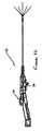
- FIG. 1is a plan view of the multiple antenna ablation device of the invention with the cover removed and partially in cross-section to illustrate its operation;
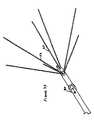
- FIG. 2is a front view of the inventive probe with anchor system of the device along lines 2 - 2 of FIG. 1 , but illustrating the instrument after deployment of the anchor and antennae (stylets);
- FIG. 3is a cross-sectional view of the tip of the catheter constructed in accordance with the present invention.
- FIG. 4is a plan view of the apparatus of the present invention with anchors and ablation hypotubes not deployed;
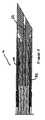
- FIG. 5is a plan view of the catheter with seven hypotube ablation electrodes and four anchors deployed;
- FIG. 6is a perspective view of the catheter structure of FIG. 5 ;
- FIG. 7is a cross-sectional view illustrating deployed hypotubes and anchors
- FIG. 8is a plan view illustrating a trocar point with deflection surfaces for guiding hypotubes
- FIG. 9is a perspective view illustrating a trocar point with deflection surfaces for guiding hypotubes
- FIG. 10is a top plan view illustrating a trocar point with deflection surfaces for guiding hypotubes
- FIG. 11is a bottom plan view illustrating a trocar point with deflection surfaces for guiding hypotubes
- FIG. 12is a rear view illustrating a trocar point with deflection surfaces for guiding hypotubes
- FIG. 13is a perspective view illustrating a core for holding a plurality of hypotubes
- FIG. 14is a side plan view illustrating a core for holding a plurality of hypotubes
- FIG. 15is a rear view illustrating a core for holding a plurality of hypotubes
- FIG. 16is a side plan view illustrating a core holding a plurality of hypotubes
- FIG. 17is a perspective view illustrating a core holding a plurality of hypotubes
- FIG. 18is a rear view illustrating a core holding a plurality of hypotubes
- FIG. 19is a perspective detailed view illustrating a core holding a plurality of hypotubes
- FIG. 20is a perspective detailed view illustrating the tips of a plurality of hypotubes when they are being held in a core as illustrated in FIG. 19 ;
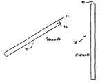
- FIG. 21is a side plan view illustrating the improved rearward anchoring member
- FIG. 22is a perspective view illustrating the rearward anchoring member of FIG. 21 ;
- FIG. 23is a partial perspective view illustrating the working relationship between the improved rearward anchoring member and a deflecting mandrel for deploying the rearward anchors with portions of the structure removed for purposes of clarity of illustration;
- FIG. 24is a perspective view from the rear of the partial perspective illustrated in FIG. 23 ;
- FIG. 25it is a perspective view illustrating the anchor-deflecting mandrel
- FIG. 26is an end view illustrating an anchor deflecting mandrel member along lines 26 - 26 of FIG. 25 ;
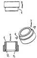
- FIG. 27is a perspective view of an insulating ring for insulating the hypotube electrodes from the anchors;
- FIG. 28is a cross-sectional view of an insulating ring for insulating the hypotube electrodes from the anchors along lines 28 - 28 of FIG. 27 ;
- FIG. 29is a side view of the insulating ring for insulating the hypotube electrodes from the anchors;
- FIG. 30is a perspective view illustrating the anchor push tube
- FIG. 31is a side plan view illustrating the anchor push tube in accordance with the present invention.
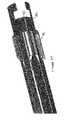
- FIG. 32is partially cross-sectional view, similar to FIG. 1 illustrating the inventive instrument with anchors and hypotubes deployed;
- FIG. 33is a detail perspective view illustrating deployment of anchors and hypotube ablation stylets.
- Instrument 10constructed in accordance with the present invention is illustrated.
- Instrument 10comprises a catheter portion 12 and a handle portion 14 .
- Ablation instrument 10is illustrated with one of the two mating handle halves removed and partially in cross section, in order to reveal its internal parts and workings in connection with the following description.
- the inventive ablation instrument 10is illustrated in the fully retracted position suitable for advancement of catheter portion 12 into tissue, for example, tissue to be subjected to ablation by being treated with radiofrequency energy.
- the catheter 12present a simple thin smooth pointed surface well-suited to penetrate healthy tissue while doing minimal damage.
- the sharpness of the point and the relatively stiff, though somewhat flexible, nature of catheter 12enables accurate steering of the point and control of the path of penetration. In the case of the treatment of uterine fibroids, such steering is achieved largely by manipulation of the uterus coupled with advancement of the catheter 12 .
- Handle portion 14includes a pair of actuators namely a stylet actuator 16 and an anchoring actuator 18 .
- Stylet actuator 16includes a serrated surface 20 .
- Anchoring actuator 18includes a pair of serrated surfaces, namely an anchor retraction surface 22 and an anchor deployment surface 24 . The application of relatively great force is facilitated by a wall 26 , against which the thumb or other finger of the surgeon may bear during the respective deployment and retraction phase of an operation performed using the inventive ablation instrument 10 .
- Stylet actuator 16 and anchoring actuator 18are supported within handle portion 14 .
- Handle portion 14comprises a left housing half 28 and a right housing half 30 symmetrical in shape to left housing half 28 , as illustrated in FIG. 2 .
- the inventive ablation instrumentmay be configured in the undeployed state.
- the inventive ablation instrument 10may be configured either with the anchors or the ablation stytlets in a deployed state, or as illustrated in FIGS. 2 , 5 , 6 and 7 with anchors and stylets both fully deployed.
- ablation instrument 10is terminated in a trocar 32 , which defines a pointed tip 34 .
- Trocar 32also functions as an electrode mandrel to deflect the tissue ablation stylets in various directions, as appears more fully below.
- Trocar 32is illustrated in FIGS. 8-12 .
- Trocar 32has a pointed tip 34 , defined by bottom surface 36 and side surfaces 38 and 40 , as illustrated most clearly in FIG. 8 .
- Surfaces 36 , 38 and 40ground into the distal portion 42 of trocar 32 .
- Trocar 32also includes a central channel 44 which extends through the length of trocar 32 and is centered on the central axis of trocar 32 .
- a plurality of deflection surfaces 46are positioned at the end of longitudinal grooves 48 , as illustrated in FIG. 9 . These surfaces 46 are configured to gently bend the flexible hypotubes which are excited with radiofrequency energy during the ablation of uterine fibroid tissue, causing them to exit catheter 12 and follow substantially straight paths through the tissue to be ablated. During this deflection, the action of deflection surfaces 46 is complemented by the inside curved surface 50 of insulative Teflon deflector ring 52 .
- the inside curved surface 50is provided with a shape which is substantially parallel the facing portion of outside surface 53 against which stylet 54 bears. This can be seen most clearly and FIG. 28 . Because a longer portion of stylet 54 is in contact with inside curved surface 50 , the spring the force exerted by stylet 54 tends to be distributed over a greater area, thus reducing friction as stylet 54 rights over surface 50 . The difference is particularly important during that portion of time when a stylet is stationary and then begins to move. It is believed that best operation occurs when the character of stylet 54 substantially matches the curvature of surface 50 .
- the angle between tangents to curved surface 50 at points on the surface of the curved portion of surface 50 and facing points on the stylets (i.e. the points which define surface portion 53 ) which are in facing relationship to each otherare 15° or less, and preferably 5° or less.
- Still yet another advantage of the relatively larger radius of the curved portion of surface 50is that stylets are bent around a radius which is relatively large, most resulting in decreasing the extent to which permanent deformation occurs, to the extent that which such permanent deformation may happen. It is noted that the extent of permanent deformation is a function of numerous factors, including the method of use, the number of times which the device is used, speed of deployment, and so forth.
- the inventive improved deflector ring 52illustrated in FIG. 27 , in addition to having a taper which is more gradual with the resulting decrease friction, is also made a material which reduces friction. Both of these factors combine to greatly reduce the tendency of the ramps in the trocar to impart a permanent bend to the stylets after repeated use.
- Preferred materials for the deflector ringare materials which are not too hard. Hard materials are not desirable because of the increased friction associated with the same. Examples of materials which have been found to be too hard include polypropylene, PEEK, nylon, and PEEK with Teflon. Superior results have been achieved with PTFE (Teflon).
- stylets 54are made of a nickel titanium alloy instead of stainless steel.
- the configuration of deflection surfaces 46is shaped to maximumize the deflection without over straining the nickel titanium alloy material of the stylets. More particularly, in accordance with the preferred embodiment of the invention, surfaces 46 are configured to result in a strain less than eight percent. Strains in the range of 2%-8% will work with strains in the range of about 4%, for example 3.5% to 4.5%, representing an easy to implement commercial solution. Less than 2% strain does not provide appreciable bending with today's technology.
- Hypotubes 54are flexible hollow tubes made of steel or nickel titanium alloy. Hypotubes 54 , as well as all other steel parts of the inventive ablation device 10 , are preferably, for economic and/or performance reasons, made of stainless steel or other high quality steel, except as indicated herein.
- the tubesdefine an internal volume 56 which contains a wire thermocouple, which performs the function of measuring the temperature of the ablated tissue which, over time, allows control of the ablation operation and ensures that the ablated tissue will become necrotic.
- the thermocouples 56are shown in only one of the tubes for purposes of clarity of illustration.
- Hypotubes 54slidably move in longitudinal grooves 48 .
- Hypotubes 54which function as ablation electrodes, are mounted on a needle core 58 , illustrated in FIGS. 13-15 .
- Needle core 58includes a plurality of longitudinal grooves 60 .
- Each of six hypotubes 54is mounted in its respective longitudinal groove 60 and secured in groove 60 by friction or through the use of an adhesive.
- a seventh hypotube 62is mounted in a central axial bore 64 .
- the assembly of hypotubes 54 and 62 in needle core 58is illustrated in FIGS. 16-18 .
- the mounting of hypotubes 54 in needle core 58is illustrated most clearly in perspective in FIG. 19 .
- Hypotubes 54may be retained in needle core 58 by any suitable means, such as a conductive cement.
- a plastic tubemay be shrink-wrapped over the assembly formed by hypotubes 54 and needle core 58 .
- hypotubes 54are preferably oriented with the flat surfaces 65 of their points oriented to slidingly cooperate with deflection surfaces 46 during deployment of the hypotubes. This is done by having the pointed tips of hypotubes 54 radially displaced from the center of catheter 12 , which prevents the pointed Ups of the hypotubes from digging into deflection surfaces 46 .
- a flexible steel electrode push tube 66is disposed around and secured to needle core 58 with the needles mounted in it. Sliding movement of the hypotubes 54 in longitudinal grooves 48 is achieved by movement of electrode push tube 66 . Movement in direction 68 causes the deployment of hypotubes 54 and 62 . Movement in direction 70 causes retraction of the hypotubes.
- a flexible steel electrode mandrel tube 74is disposed around and over electrode push tube 66 .
- Flexible steel electrode mandrel tube 74allows electrode push tube 66 to freely slide within it. This is achieved, despite the relatively large area of the tubes, because the facing surfaces of the tubes are both smooth and because there is a small gap between their facing surfaces, thus minimizing friction. Such gaps allow provision for flushing the instrument clean with water, as is done with prior art devices.
- a flexible plastic tubular insulative member 76is disposed around and over electrode mandrel tube 74 .
- Insulative member 76isolates electrical radiofrequency ablation energy (carried by push tube 66 for exciting hypotubes 54 and 62 ) from anchor push tube 78 . This allows electrical ablation energy to be optionally applied to anchor push tube 78 to independently cause the anchors 80 on anchor member 82 to apply ablation energy to a different volume than that which is ablated by the electrode stylets 54 and 62 .
- Anchor member 82is illustrated in FIGS. 21-23 .
- Anchors 80are made, for example, by being cut using a laser from a steel tube to form steel anchor member 82 .
- Each anchor 80has a tip 84 which lies generally within the circular cylindrical surface defined by the tube from which it has been cut.
- the inside surface 83 of tip 84is positioned radially outwardly with respect to the leading edges 85 of deflection surfaces 88 to facilitate deflection over anchor mandrel 86 in response to movement of anchor member 82 in the direction of arrow 70 .
- Anchor tips 84come to a point forming an angle of about 60°, in accordance with the preferred embodiment. Angles ranging between 45° and 75° are preferred with angles in the range of 55° to 65° being particularly preferred. In accordance with a preferred embodiment a smooth surface extending from tips 84 to the base of the anchors is preferred.
- Anchor mandrel 86is illustrated in FIGS. 24-26 .
- Anchor mandrel 86which may be made of stainless steel incorporates a number of deflection surfaces 88 , as illustrated most clearly in FIGS. 7 and 25 .
- anchor member 82and thus anchors 80 , are made of a nickel titanium alloy instead of stainless steel.
- Nickel titanium alloyis a preferred material for both anchors 80 and stylets 54 .
- the configuration of deflection surfaces 88is shaped to maximize the deflection without over-straining the nickel titanium alloy material of the anchors.
- the provision of anchors with points forming approximately 60° anglesis particularly advantageous in this regard.
- the anchorsmay have a cylindrical shape, in order to fit securely and compactly with in the inventive instrument. Accordingly, the avoidance of excessive mechanical strain is additionally important, and the narrower taper assists in this regard. While points with angles in the range of about 60°, as detailed herein are preferred, angles ranging from very pointed, for example five or 10° and 60° and somewhat larger angles provide results which are superior to those achieved with, for example, 90° points.
- surfaces 88are configured to result in a strain less than eight percent, even with relatively wide points, for example 90° points. With such 90° points, strains in the range of 2-8% will work with strains in the range of about 4%, for example 3.5 to 4.5%, are less rigorously 3% to 5%, representing an easy to implement commercial solution. Higher performance may be obtained by maintaining a deflection angle which results in a strain of 6-7%. Configuring surface 88 to result in strains approaching 8%, for example 7.5% will maximize deflection and flexibility in design of ablation volume, but will tend to result in quicker degradation of anchors 80 . However, if a particular procedure does not involve a great number of ablations, or the use of several disposable ablation catheters 10 is acceptable, such devices under certain circumstances do present advantages.
- the structure of the distal end of catheter portion 12is completed by a steel anchor cover 90 , which is supported on, surrounds and is secured to insulating ring 52 whose structure is illustrated in FIGS. 27-29 .
- anchors 80pass between deflection surfaces 88 and the inside surface of steel anchor cover 90 .
- Anchor push tube 78illustrated in FIGS. 30 and 31 includes a pair of keys 92 which are shaped like the letter T. Keys 92 mate with slots 94 ( FIG. 22 ) in anchor member 82 . Anchor member 82 and anchor push tube 78 thus act as a unitary member during deployment and retraction of anchors 80 , in response to sliding motion of anchor member 82 and anchor push tube 78 .
- Anchor member 82generally defines a plurality of supports 99 on opposite sides of each anchor 80 , as illustrated in FIGS. 21 and 22 . Supports 99 ride within axially extending tracks 101 which are defined on the inside surface of anchor mandrel 86 , as illustrated in FIGS. 24 and 25 .
- anchor mandrel 86defines a plurality of actually extending raised services 103 which are disposed circumferentially in between supports 99 when anchors 80 are deflected outwardly.
- catheter 12The structure of catheter 12 is completed by outer tube 96 which is secured to handle 14 at one end and secured to a tubular slip ring 98 which slides over anchor push tube 78 .
- FIG. 1illustrates the relative positions of anchoring actuator 18 , and stylet actuator 16 before deployment of anchors and stylets. This corresponds to FIG. 4 .
- Electrode mandrel tube 74is secured at its proximal end to handle 14 . At its distal end, electrode mandrel tube 74 is secured to trocar 32 , for example by a quantity of epoxy adhesive 100 in the annular groove 102 on trocar 32 , as illustrated in FIG. 3 . Alternately, instead of or in addition to using an adhesive, electrode mandrel tube 74 may be crimped. Stylet actuator 16 is secured to electrode push tube 66 . Thus, movement in the direction of arrow 68 in FIG. 1 causes the stylets to emerge from the end of the catheter as illustrated in FIGS. 5 , 6 , 7 and 32 . Full deployment of ablation electrodes or stylets 54 and 62 is illustrated most clearly in FIG. 33 .
- Anchoring actuator 18is secured to anchor push tube 78 .
- electrode mandrel tube 74is secured to anchor mandrel 86 , for example by a quantity of epoxy adhesive. Accordingly, movement of anchoring actuator 18 , in the direction of arrow 70 in FIG. 1 , causes the anchors 80 to emerge from the catheter as illustrated in FIGS. 5 , 6 , 7 and 32 . Full deployment of anchors 80 is illustrated most clearly in FIG. 33 .
- control of the inventive ablation device 10will be achieved by one or two electrical switches 104 and 106 .
- Operation of switch 106will cause the appearance of a menu on a display, for example by axial movement of switch 106 in the manner of a joystick.
- Transverse movement of switch 106causes the menu to switch between different menu items, such as controlling ablation time, controlling ablation temperature, or some other parameter.
- Selection of the desired value for the selected parameteris achieved by transverse motion of switch 106 , causing the various values to be displayed on the display.
- depression of switch 104registers that value with the electronic circuit controlling ablation and causes the inventive ablation device 10 to be operated in accordance with the selected parameter.
- RF ablation energy, control signals, and temperature measurement signalsare coupled from the inventive ablation device 10 to a control unit/RF energy source by a connector 108 .
- a conventional radiofrequency energy sourcesuch as that used in conventional ablation systems would be employed in conjunction with the inventive ablation device 10 .
- cauterization radiofrequency energymay also be applied to trocar 32 during withdrawal of trocar 32 from the patient in order to control loss of blood. It is noted that the nature of the RE signal needed to achieve cautery is different from the nature of an ablation signal. Both of these signals are well defined in the art. Likewise, their generation is also well-known. However, in accordance of the present invention conventional cautery and conventional ablation signals may be used for cautery and ablation, respectively.
- inventive devicehas been illustrated for use in the ablation of uterine fibroids, it is understood that this particular implementation is exemplary and that the inventive device may be employed in a wide variety of circumstances. Likewise, while an illustrative embodiment of the invention has been described, it is understood that various modifications to the structure of the disclosed device will be obvious to those of ordinary skill in the art. Such modifications are within the spirit and scope of the invention which is limited and defined only by the appended claims.
Landscapes
- Health & Medical Sciences (AREA)
- Surgery (AREA)
- Life Sciences & Earth Sciences (AREA)
- Biomedical Technology (AREA)
- Medical Informatics (AREA)
- Reproductive Health (AREA)
- Pregnancy & Childbirth (AREA)
- Engineering & Computer Science (AREA)
- Gynecology & Obstetrics (AREA)
- Heart & Thoracic Surgery (AREA)
- Nuclear Medicine, Radiotherapy & Molecular Imaging (AREA)
- Molecular Biology (AREA)
- Animal Behavior & Ethology (AREA)
- General Health & Medical Sciences (AREA)
- Public Health (AREA)
- Veterinary Medicine (AREA)
- Surgical Instruments (AREA)
- Prostheses (AREA)
Abstract
Description
Claims (17)
Priority Applications (12)
| Application Number | Priority Date | Filing Date | Title |
|---|---|---|---|
| US11/940,294US8251991B2 (en) | 2007-11-14 | 2007-11-14 | Anchored RF ablation device for the destruction of tissue masses |
| KR1020107013106AKR20100117558A (en) | 2007-11-14 | 2008-11-14 | Anchored rf ablation device for the destruction of tissue masses |
| CA2715736ACA2715736A1 (en) | 2007-11-14 | 2008-11-14 | Anchored rf ablation device for the destruction of tissue masses |
| PCT/US2008/083617WO2009065025A1 (en) | 2007-11-14 | 2008-11-14 | Anchored rf ablation device for the destruction of tissue masses |
| MX2010005407AMX2010005407A (en) | 2007-11-14 | 2008-11-14 | Anchored rf ablation device for the destruction of tissue masses. |
| EP08848852AEP2219552A4 (en) | 2007-11-14 | 2008-11-14 | Anchored rf ablation device for the destruction of tissue masses |
| AU2008322493AAU2008322493A1 (en) | 2007-11-14 | 2008-11-14 | Anchored RF ablation device for the destruction of tissue masses |
| CN2008801226987ACN101932288A (en) | 2007-11-14 | 2008-11-14 | Anchored RF ablation device for the destruction of tissue masses |
| JP2010534223AJP2011502721A (en) | 2007-11-14 | 2008-11-14 | Fixed high-frequency cutting device for breaking tissue clumps |
| RU2010123935/14ARU2010123935A (en) | 2007-11-14 | 2008-11-14 | ATTACHED DEVICE FOR RADIO FREQUENCY ABLATION, INTENDED FOR DESTRUCTION OF TISSUE MASSES |
| BRPI0819321BRPI0819321A2 (en) | 2007-11-14 | 2008-11-14 | Anchorage mechanisms for ablation elements and ablation devices. |
| IL205798AIL205798A (en) | 2007-11-14 | 2010-05-16 | Anchored rf ablation device for the destruction of tissue masses |
Applications Claiming Priority (1)
| Application Number | Priority Date | Filing Date | Title |
|---|---|---|---|
| US11/940,294US8251991B2 (en) | 2007-11-14 | 2007-11-14 | Anchored RF ablation device for the destruction of tissue masses |
Publications (2)
| Publication Number | Publication Date |
|---|---|
| US20090221998A1 US20090221998A1 (en) | 2009-09-03 |
| US8251991B2true US8251991B2 (en) | 2012-08-28 |
Family
ID=40639166
Family Applications (1)
| Application Number | Title | Priority Date | Filing Date |
|---|---|---|---|
| US11/940,294Active2031-03-28US8251991B2 (en) | 2007-11-14 | 2007-11-14 | Anchored RF ablation device for the destruction of tissue masses |
Country Status (12)
| Country | Link |
|---|---|
| US (1) | US8251991B2 (en) |
| EP (1) | EP2219552A4 (en) |
| JP (1) | JP2011502721A (en) |
| KR (1) | KR20100117558A (en) |
| CN (1) | CN101932288A (en) |
| AU (1) | AU2008322493A1 (en) |
| BR (1) | BRPI0819321A2 (en) |
| CA (1) | CA2715736A1 (en) |
| IL (1) | IL205798A (en) |
| MX (1) | MX2010005407A (en) |
| RU (1) | RU2010123935A (en) |
| WO (1) | WO2009065025A1 (en) |
Cited By (2)
| Publication number | Priority date | Publication date | Assignee | Title |
|---|---|---|---|---|
| WO2015148445A1 (en)* | 2014-03-24 | 2015-10-01 | Old Dominion University Research Foundation | Expandable catheter devices electrode array |
| WO2019094808A1 (en) | 2017-11-09 | 2019-05-16 | Acessa Health Inc. | System for controlling ablation treatment and visualization |
Families Citing this family (27)
| Publication number | Priority date | Publication date | Assignee | Title |
|---|---|---|---|---|
| US8512330B2 (en)* | 2005-07-01 | 2013-08-20 | Halt Medical Inc. | Ablation method |
| US8080009B2 (en) | 2005-07-01 | 2011-12-20 | Halt Medical Inc. | Radio frequency ablation device for the destruction of tissue masses |
| US12290277B2 (en) | 2007-01-02 | 2025-05-06 | Aquabeam, Llc | Tissue resection with pressure sensing |
| ES2769535T3 (en)* | 2008-03-06 | 2020-06-26 | Aquabeam Llc | Tissue ablation and cauterization with optical energy carried in a fluid stream |
| US9561066B2 (en) | 2008-10-06 | 2017-02-07 | Virender K. Sharma | Method and apparatus for tissue ablation |
| US9700365B2 (en) | 2008-10-06 | 2017-07-11 | Santa Anna Tech Llc | Method and apparatus for the ablation of gastrointestinal tissue |
| US10695126B2 (en) | 2008-10-06 | 2020-06-30 | Santa Anna Tech Llc | Catheter with a double balloon structure to generate and apply a heated ablative zone to tissue |
| US10064697B2 (en) | 2008-10-06 | 2018-09-04 | Santa Anna Tech Llc | Vapor based ablation system for treating various indications |
| US9561068B2 (en) | 2008-10-06 | 2017-02-07 | Virender K. Sharma | Method and apparatus for tissue ablation |
| EP3556308B1 (en) | 2009-11-05 | 2023-12-20 | Stratus Medical, LLC | Systems for spinal radio frequency neurotomy |
| KR101632429B1 (en) | 2010-05-21 | 2016-06-21 | 님버스 컨셉츠, 엘엘씨 | Systems and methods for tissue ablation |
| CN102188304B (en)* | 2010-12-31 | 2012-12-05 | 清华大学 | Hollow tubular multi-warhead nano tumor heat therapy instrument |
| EP2688470B1 (en)* | 2011-03-23 | 2020-11-04 | Acessa Health Inc. | Merged image user interface and navigational tool for remote control of surgical devices |
| EP3351196A1 (en) | 2012-02-29 | 2018-07-25 | Procept Biorobotics Corporation | Automated image-guided tissue resection and treatment |
| EP3964151A3 (en) | 2013-01-17 | 2022-03-30 | Virender K. Sharma | Apparatus for tissue ablation |
| US9198719B2 (en)* | 2013-09-30 | 2015-12-01 | Gyrus Acmi, Inc. | Electrosurgical fibroid ablation system and method |
| JP6229077B2 (en)* | 2014-07-11 | 2017-11-08 | ボストン サイエンティフィック サイムド,インコーポレイテッドBoston Scientific Scimed,Inc. | Ablation medical devices |
| EP4215135B8 (en) | 2015-06-17 | 2025-01-01 | Stryker European Operations Holdings LLC | Surgical instrument with ultrasonic tip for fibrous tissue removal |
| US12364537B2 (en) | 2016-05-02 | 2025-07-22 | Santa Anna Tech Llc | Catheter with a double balloon structure to generate and apply a heated ablative zone to tissue |
| US11331140B2 (en) | 2016-05-19 | 2022-05-17 | Aqua Heart, Inc. | Heated vapor ablation systems and methods for treating cardiac conditions |
| US11819199B2 (en) | 2018-04-30 | 2023-11-21 | Boston Scientific Scimed, Inc. | Ramped biopsy needle device |
| EP3801324B1 (en) | 2018-06-01 | 2025-05-28 | Aqua Medical, Inc. | Vapor generation and delivery systems |
| CN109106432B (en)* | 2018-06-19 | 2022-08-12 | 余军辉 | Device for removing ectopic pregnancy focus through natural cavity and using method thereof |
| CN110179538B (en)* | 2019-04-28 | 2021-06-11 | 华中科技大学 | Multi-claw conformal ablation needle with nested structure |
| WO2022141769A1 (en)* | 2020-12-31 | 2022-07-07 | 杭州堃博生物科技有限公司 | Radio-frequency ablation catheter and radio-frequency ablation system |
| CN112641503A (en)* | 2020-12-25 | 2021-04-13 | 山西白求恩医院(山西医学科学院) | Tumor radio frequency ablation device |
| CN113936520B (en)* | 2021-10-14 | 2022-06-21 | 中国人民解放军总医院第四医学中心 | Radio frequency ablation simulation training device |
Citations (124)
| Publication number | Priority date | Publication date | Assignee | Title |
|---|---|---|---|---|
| US35330A (en) | 1862-05-20 | Improved foot corn-planter | ||
| DE2124684A1 (en) | 1971-05-18 | 1972-11-30 | Stadelmann W | Puncture electrode |
| US3991770A (en) | 1974-01-24 | 1976-11-16 | Leveen Harry H | Method for treating benign and malignant tumors utilizing radio frequency, electromagnetic radiation |
| US4016886A (en) | 1974-11-26 | 1977-04-12 | The United States Of America As Represented By The United States Energy Research And Development Administration | Method for localizing heating in tumor tissue |
| US4074718A (en) | 1976-03-17 | 1978-02-21 | Valleylab, Inc. | Electrosurgical instrument |
| US4080959A (en) | 1976-06-18 | 1978-03-28 | Leveen Robert F | Method for detection of tumors of the breast |
| US4095602A (en) | 1976-09-27 | 1978-06-20 | Leveen Harry H | Multi-portal radiofrequency generator |
| US4119102A (en) | 1975-07-11 | 1978-10-10 | Leveen Harry H | Radio frequency treatment of tumors while inducing hypotension |
| US4140130A (en) | 1977-05-31 | 1979-02-20 | Storm Iii Frederick K | Electrode structure for radio frequency localized heating of tumor bearing tissue |
| US4154246A (en) | 1977-07-25 | 1979-05-15 | Leveen Harry H | Field intensification in radio frequency thermotherapy |
| US4230129A (en) | 1975-07-11 | 1980-10-28 | Leveen Harry H | Radio frequency, electromagnetic radiation device having orbital mount |
| US4285346A (en) | 1979-03-14 | 1981-08-25 | Harry V. LeVeen | Electrode system |
| US4290435A (en) | 1979-09-07 | 1981-09-22 | Thermatime A.G. | Internally cooled electrode for hyperthermal treatment and method of use |
| US4303636A (en) | 1974-08-20 | 1981-12-01 | Gordon Robert T | Cancer treatment |
| US4346715A (en) | 1978-07-12 | 1982-08-31 | The United States Of America As Represented By The Administrator Of The National Aeronautics And Space Administration | Hyperthermia heating apparatus |
| US4375220A (en) | 1980-05-09 | 1983-03-01 | Matvias Fredrick M | Microwave applicator with cooling mechanism for intracavitary treatment of cancer |
| US4545368A (en) | 1983-04-13 | 1985-10-08 | Rand Robert W | Induction heating method for use in causing necrosis of neoplasm |
| US4565200A (en) | 1980-09-24 | 1986-01-21 | Cosman Eric R | Universal lesion and recording electrode system |
| US4676258A (en) | 1983-01-24 | 1987-06-30 | Kureha Kagaku Kogyo Kabushiki Kaisha | Device for hyperthermia |
| US4709701A (en) | 1986-04-15 | 1987-12-01 | Medical Research & Development Associates | Apparatus for medical treatment by hyperthermia |
| US4773864A (en) | 1987-08-31 | 1988-09-27 | Holt Byron B | Apparatus for enhancing surgical skills |
| US4823791A (en) | 1987-05-08 | 1989-04-25 | Circon Acmi Division Of Circon Corporation | Electrosurgical probe apparatus |
| US4881543A (en) | 1988-06-28 | 1989-11-21 | Massachusetts Institute Of Technology | Combined microwave heating and surface cooling of the cornea |
| US4887614A (en) | 1983-09-05 | 1989-12-19 | Kureha Kagaku Kogyo Kabushiki Kaisha | Medical electrode device |
| US4955884A (en) | 1988-06-02 | 1990-09-11 | Circon Corporation | System for reducing drag on the movement of an electrode in a resectoscope |
| US4962761A (en) | 1987-02-24 | 1990-10-16 | Golden Theodore A | Thermal bandage |
| US5003991A (en) | 1987-03-31 | 1991-04-02 | Olympus Optical Co., Ltd. | Hyperthermia apparatus |
| US5007908A (en) | 1989-09-29 | 1991-04-16 | Everest Medical Corporation | Electrosurgical instrument having needle cutting electrode and spot-coag electrode |
| US5010897A (en) | 1989-04-26 | 1991-04-30 | Leveen Harry H | Apparatus for deep heating of cancer |
| US5099756A (en) | 1989-06-01 | 1992-03-31 | Harry H. Leveen | Radio frequency thermotherapy |
| US5151101A (en) | 1988-06-02 | 1992-09-29 | Circon Corporation | System for disconnectably mounting an endoscope sheath with an endoscope tool |
| US5190541A (en) | 1990-10-17 | 1993-03-02 | Boston Scientific Corporation | Surgical instrument and method |
| US5190517A (en) | 1991-06-06 | 1993-03-02 | Valleylab Inc. | Electrosurgical and ultrasonic surgical system |
| US5234004A (en) | 1988-11-21 | 1993-08-10 | Technomed International | Method and apparatus for the surgical treatment of tissues by thermal effect, and in particular the prostate, using a urethral microwave-emitting probe means |
| US5257451A (en) | 1991-11-08 | 1993-11-02 | Ep Technologies, Inc. | Method of making durable sleeve for enclosing a bendable electrode tip assembly |
| US5273535A (en) | 1991-11-08 | 1993-12-28 | Ep Technologies, Inc. | Catheter with electrode tip having asymmetric left and right curve configurations |
| US5275162A (en) | 1991-11-08 | 1994-01-04 | Ep Technologies, Inc. | Valve mapping catheter |
| US5282797A (en) | 1989-05-30 | 1994-02-01 | Cyrus Chess | Method for treating cutaneous vascular lesions |
| US5293863A (en) | 1992-05-08 | 1994-03-15 | Loma Linda University Medical Center | Bladed endoscopic retractor |
| US5293869A (en) | 1992-09-25 | 1994-03-15 | Ep Technologies, Inc. | Cardiac probe with dynamic support for maintaining constant surface contact during heart systole and diastole |
| US5309910A (en) | 1992-09-25 | 1994-05-10 | Ep Technologies, Inc. | Cardiac mapping and ablation systems |
| US5314466A (en) | 1992-04-13 | 1994-05-24 | Ep Technologies, Inc. | Articulated unidirectional microwave antenna systems for cardiac ablation |
| US5313943A (en) | 1992-09-25 | 1994-05-24 | Ep Technologies, Inc. | Catheters and methods for performing cardiac diagnosis and treatment |
| US5322503A (en) | 1991-10-18 | 1994-06-21 | Desai Ashvin H | Endoscopic surgical instrument |
| US5328467A (en) | 1991-11-08 | 1994-07-12 | Ep Technologies, Inc. | Catheter having a torque transmitting sleeve |
| US5334193A (en) | 1992-11-13 | 1994-08-02 | American Cardiac Ablation Co., Inc. | Fluid cooled ablation catheter |
| US5342357A (en) | 1992-11-13 | 1994-08-30 | American Cardiac Ablation Co., Inc. | Fluid cooled electrosurgical cauterization system |
| US5348554A (en) | 1992-12-01 | 1994-09-20 | Cardiac Pathways Corporation | Catheter for RF ablation with cooled electrode |
| US5363861A (en) | 1991-11-08 | 1994-11-15 | Ep Technologies, Inc. | Electrode tip assembly with variable resistance to bending |
| US5366490A (en) | 1992-08-12 | 1994-11-22 | Vidamed, Inc. | Medical probe device and method |
| US5368592A (en) | 1992-04-13 | 1994-11-29 | Ep Technologies, Inc. | Articulated systems for cardiac ablation |
| US5370678A (en) | 1992-04-13 | 1994-12-06 | Ep Technologies, Inc. | Steerable microwave antenna systems for cardiac ablation that minimize tissue damage and blood coagulation due to conductive heating patterns |
| US5383917A (en) | 1991-07-05 | 1995-01-24 | Jawahar M. Desai | Device and method for multi-phase radio-frequency ablation |
| US5385544A (en) | 1992-08-12 | 1995-01-31 | Vidamed, Inc. | BPH ablation method and apparatus |
| US5398683A (en) | 1991-05-24 | 1995-03-21 | Ep Technologies, Inc. | Combination monophasic action potential/ablation catheter and high-performance filter system |
| US5403311A (en) | 1993-03-29 | 1995-04-04 | Boston Scientific Corporation | Electro-coagulation and ablation and other electrotherapeutic treatments of body tissue |
| US5409453A (en) | 1992-08-12 | 1995-04-25 | Vidamed, Inc. | Steerable medical probe with stylets |
| US5423807A (en) | 1992-04-16 | 1995-06-13 | Implemed, Inc. | Cryogenic mapping and ablation catheter |
| US5423808A (en) | 1991-11-08 | 1995-06-13 | Ep Technologies, Inc. | Systems and methods for radiofrequency ablation with phase sensitive power detection |
| US5433708A (en) | 1991-05-17 | 1995-07-18 | Innerdyne, Inc. | Method and device for thermal ablation having improved heat transfer |
| US5435805A (en) | 1992-08-12 | 1995-07-25 | Vidamed, Inc. | Medical probe device with optical viewing capability |
| US5456662A (en) | 1993-02-02 | 1995-10-10 | Edwards; Stuart D. | Method for reducing snoring by RF ablation of the uvula |
| US5458597A (en) | 1993-11-08 | 1995-10-17 | Zomed International | Device for treating cancer and non-malignant tumors and methods |
| US5458596A (en) | 1994-05-06 | 1995-10-17 | Dorsal Orthopedic Corporation | Method and apparatus for controlled contraction of soft tissue |
| US5462521A (en) | 1993-12-21 | 1995-10-31 | Angeion Corporation | Fluid cooled and perfused tip for a catheter |
| US5470308A (en) | 1992-08-12 | 1995-11-28 | Vidamed, Inc. | Medical probe with biopsy stylet |
| US5470309A (en) | 1992-08-12 | 1995-11-28 | Vidamed, Inc. | Medical ablation apparatus utilizing a heated stylet |
| US5471982A (en) | 1992-09-29 | 1995-12-05 | Ep Technologies, Inc. | Cardiac mapping and ablation systems |
| US5472441A (en) | 1993-11-08 | 1995-12-05 | Zomed International | Device for treating cancer and non-malignant tumors and methods |
| US5484400A (en) | 1992-08-12 | 1996-01-16 | Vidamed, Inc. | Dual channel RF delivery system |
| US5486161A (en) | 1993-02-02 | 1996-01-23 | Zomed International | Medical probe device and method |
| US5505730A (en) | 1994-06-24 | 1996-04-09 | Stuart D. Edwards | Thin layer ablation apparatus |
| US5507743A (en) | 1993-11-08 | 1996-04-16 | Zomed International | Coiled RF electrode treatment apparatus |
| US5514131A (en) | 1992-08-12 | 1996-05-07 | Stuart D. Edwards | Method for the ablation treatment of the uvula |
| US5514130A (en) | 1994-10-11 | 1996-05-07 | Dorsal Med International | RF apparatus for controlled depth ablation of soft tissue |
| US5536267A (en) | 1993-11-08 | 1996-07-16 | Zomed International | Multiple electrode ablation apparatus |
| US5542916A (en) | 1992-08-12 | 1996-08-06 | Vidamed, Inc. | Dual-channel RF power delivery system |
| US5542928A (en) | 1991-05-17 | 1996-08-06 | Innerdyne, Inc. | Method and device for thermal ablation having improved heat transfer |
| US5542915A (en) | 1992-08-12 | 1996-08-06 | Vidamed, Inc. | Thermal mapping catheter with ultrasound probe |
| US5545193A (en) | 1993-10-15 | 1996-08-13 | Ep Technologies, Inc. | Helically wound radio-frequency emitting electrodes for creating lesions in body tissue |
| US5546267A (en) | 1994-12-08 | 1996-08-13 | Illinois Tool Works Inc. | Communication circuit protector |
| US5545171A (en) | 1994-09-22 | 1996-08-13 | Vidamed, Inc. | Anastomosis catheter |
| US5545161A (en) | 1992-12-01 | 1996-08-13 | Cardiac Pathways Corporation | Catheter for RF ablation having cooled electrode with electrically insulated sleeve |
| US5549108A (en) | 1992-09-25 | 1996-08-27 | Ep Technologies, Inc. | Cardiac mapping and ablation systems |
| US5549644A (en) | 1992-08-12 | 1996-08-27 | Vidamed, Inc. | Transurethral needle ablation device with cystoscope and method for treatment of the prostate |
| US5556377A (en) | 1992-08-12 | 1996-09-17 | Vidamed, Inc. | Medical probe apparatus with laser and/or microwave monolithic integrated circuit probe |
| US5558673A (en) | 1994-09-30 | 1996-09-24 | Vidamed, Inc. | Medical probe device and method having a flexible resilient tape stylet |
| US5560358A (en) | 1994-09-08 | 1996-10-01 | Radionics, Inc. | Connector design for multi-contact medical electrode |
| US5562703A (en) | 1994-06-14 | 1996-10-08 | Desai; Ashvin H. | Endoscopic surgical instrument |
| US5582610A (en) | 1994-09-30 | 1996-12-10 | Circon Corporation | Grooved slider electrode for a resectoscope |
| US5662680A (en) | 1991-10-18 | 1997-09-02 | Desai; Ashvin H. | Endoscopic surgical instrument |
| US5672173A (en) | 1995-08-15 | 1997-09-30 | Rita Medical Systems, Inc. | Multiple antenna ablation apparatus and method |
| US5672174A (en) | 1995-08-15 | 1997-09-30 | Rita Medical Systems, Inc. | Multiple antenna ablation apparatus and method |
| US5683384A (en) | 1993-11-08 | 1997-11-04 | Zomed | Multiple antenna ablation apparatus |
| US5728143A (en) | 1995-08-15 | 1998-03-17 | Rita Medical Systems, Inc. | Multiple antenna ablation apparatus and method |
| US5759162A (en) | 1992-03-10 | 1998-06-02 | Siemens Aktiengesellschaft | Method and apparatus for ultrasound tissue therapy |
| US5782827A (en) | 1995-08-15 | 1998-07-21 | Rita Medical Systems, Inc. | Multiple antenna ablation apparatus and method with multiple sensor feedback |
| US5911036A (en) | 1995-09-15 | 1999-06-08 | Computer Motion, Inc. | Head cursor control interface for an automated endoscope system for optimal positioning |
| US5935123A (en) | 1993-11-08 | 1999-08-10 | Rita Medical Systems, Inc. | RF treatment apparatus |
| US5979453A (en) | 1995-11-09 | 1999-11-09 | Femrx, Inc. | Needle myolysis system for uterine fibriods |
| US6002968A (en) | 1994-06-24 | 1999-12-14 | Vidacare, Inc. | Uterine treatment apparatus |
| US6036689A (en) | 1998-09-24 | 2000-03-14 | Tu; Lily Chen | Ablation device for treating atherosclerotic tissues |
| US6066139A (en) | 1996-05-14 | 2000-05-23 | Sherwood Services Ag | Apparatus and method for sterilization and embolization |
| US6071280A (en) | 1993-11-08 | 2000-06-06 | Rita Medical Systems, Inc. | Multiple electrode ablation apparatus |
| US6190383B1 (en) | 1998-10-21 | 2001-02-20 | Sherwood Services Ag | Rotatable electrode device |
| US6212433B1 (en) | 1998-07-28 | 2001-04-03 | Radiotherapeutics Corporation | Method for treating tumors near the surface of an organ |
| US6217518B1 (en) | 1998-10-01 | 2001-04-17 | Situs Corporation | Medical instrument sheath comprising a flexible ultrasound transducer |
| US6254601B1 (en) | 1998-12-08 | 2001-07-03 | Hysterx, Inc. | Methods for occlusion of the uterine arteries |
| US20010012956A1 (en)* | 1998-07-28 | 2001-08-09 | Behl Robert S. | Apparatus and method for treating tumors near the surface of an organ |
| US6355033B1 (en) | 1999-06-17 | 2002-03-12 | Vivant Medical | Track ablation device and methods of use |
| US20020120260A1 (en)* | 2001-02-28 | 2002-08-29 | Morris David L. | Tissue surface treatment apparatus and method |
| US6468273B1 (en) | 1995-03-24 | 2002-10-22 | The Board Of Regents Of The University Of Nebraska | Methods for volumetric tissue ablation |
| US6575967B1 (en) | 1995-03-24 | 2003-06-10 | The Board Of Regents Of The University Of Nebraska | Method and systems for volumetric tissue ablation |
| US6575969B1 (en) | 1995-05-04 | 2003-06-10 | Sherwood Services Ag | Cool-tip radiofrequency thermosurgery electrode system for tumor ablation |
| US20030125729A1 (en) | 2000-04-27 | 2003-07-03 | Hooven Michael D. | Transmural ablation device |
| US20030130711A1 (en) | 2001-09-28 | 2003-07-10 | Pearson Robert M. | Impedance controlled tissue ablation apparatus and method |
| US20030199868A1 (en) | 1991-07-05 | 2003-10-23 | Desai Jawahar M. | Device and method for multi-phase radio-frequency ablation |
| US20040215182A1 (en) | 2000-08-09 | 2004-10-28 | Lee Bruce B | Gynecological ablation procedure and system using an ablation needle |
| US20040254572A1 (en) | 2003-04-25 | 2004-12-16 | Mcintyre Jon T. | Self anchoring radio frequency ablation array |
| US6837887B2 (en) | 1995-06-07 | 2005-01-04 | Arthrocare Corporation | Articulated electrosurgical probe and methods |
| US20050149013A1 (en) | 2000-08-09 | 2005-07-07 | Lee Bruce B. | Gynecological ablation procedure and system |
| US6958062B1 (en)* | 1993-11-08 | 2005-10-25 | Rita Medical Systems, Inc. | Multiple antenna ablation apparatus and method |
| US20060189972A1 (en) | 2005-02-02 | 2006-08-24 | Gynesonics, Inc. | Method and device for uterine fibroid treatment |
| US20070016183A1 (en)* | 2005-07-01 | 2007-01-18 | Bruce Lee | Radio frequency ablation device for the destruction of tissue masses |
Family Cites Families (5)
| Publication number | Priority date | Publication date | Assignee | Title |
|---|---|---|---|---|
| US6719755B2 (en)* | 1996-10-22 | 2004-04-13 | Epicor Medical, Inc. | Methods and devices for ablation |
| US5925041A (en)* | 1997-05-14 | 1999-07-20 | Ethicon Endo-Surgery, Inc. | Monopolar electrosurgical trocar |
| US7458971B2 (en)* | 2004-09-24 | 2008-12-02 | Boston Scientific Scimed, Inc. | RF ablation probe with unibody electrode element |
| SG121919A1 (en)* | 2004-10-26 | 2006-05-26 | Poh Choo Mona Tan | Device for cauterising tissue and uses thereof |
| US8512333B2 (en)* | 2005-07-01 | 2013-08-20 | Halt Medical Inc. | Anchored RF ablation device for the destruction of tissue masses |
- 2007
- 2007-11-14USUS11/940,294patent/US8251991B2/enactiveActive
- 2008
- 2008-11-14CACA2715736Apatent/CA2715736A1/ennot_activeAbandoned
- 2008-11-14WOPCT/US2008/083617patent/WO2009065025A1/enactiveApplication Filing
- 2008-11-14CNCN2008801226987Apatent/CN101932288A/enactivePending
- 2008-11-14RURU2010123935/14Apatent/RU2010123935A/ennot_activeApplication Discontinuation
- 2008-11-14MXMX2010005407Apatent/MX2010005407A/enactiveIP Right Grant
- 2008-11-14KRKR1020107013106Apatent/KR20100117558A/ennot_activeWithdrawn
- 2008-11-14EPEP08848852Apatent/EP2219552A4/ennot_activeWithdrawn
- 2008-11-14AUAU2008322493Apatent/AU2008322493A1/ennot_activeAbandoned
- 2008-11-14JPJP2010534223Apatent/JP2011502721A/enactivePending
- 2008-11-14BRBRPI0819321patent/BRPI0819321A2/ennot_activeIP Right Cessation
- 2010
- 2010-05-16ILIL205798Apatent/IL205798A/ennot_activeIP Right Cessation
Patent Citations (132)
| Publication number | Priority date | Publication date | Assignee | Title |
|---|---|---|---|---|
| US35330A (en) | 1862-05-20 | Improved foot corn-planter | ||
| DE2124684A1 (en) | 1971-05-18 | 1972-11-30 | Stadelmann W | Puncture electrode |
| US3991770A (en) | 1974-01-24 | 1976-11-16 | Leveen Harry H | Method for treating benign and malignant tumors utilizing radio frequency, electromagnetic radiation |
| US4303636A (en) | 1974-08-20 | 1981-12-01 | Gordon Robert T | Cancer treatment |
| US4016886A (en) | 1974-11-26 | 1977-04-12 | The United States Of America As Represented By The United States Energy Research And Development Administration | Method for localizing heating in tumor tissue |
| US4230129A (en) | 1975-07-11 | 1980-10-28 | Leveen Harry H | Radio frequency, electromagnetic radiation device having orbital mount |
| US4119102A (en) | 1975-07-11 | 1978-10-10 | Leveen Harry H | Radio frequency treatment of tumors while inducing hypotension |
| US4074718A (en) | 1976-03-17 | 1978-02-21 | Valleylab, Inc. | Electrosurgical instrument |
| US4080959A (en) | 1976-06-18 | 1978-03-28 | Leveen Robert F | Method for detection of tumors of the breast |
| US4095602A (en) | 1976-09-27 | 1978-06-20 | Leveen Harry H | Multi-portal radiofrequency generator |
| US4140130A (en) | 1977-05-31 | 1979-02-20 | Storm Iii Frederick K | Electrode structure for radio frequency localized heating of tumor bearing tissue |
| US4154246A (en) | 1977-07-25 | 1979-05-15 | Leveen Harry H | Field intensification in radio frequency thermotherapy |
| US4346715A (en) | 1978-07-12 | 1982-08-31 | The United States Of America As Represented By The Administrator Of The National Aeronautics And Space Administration | Hyperthermia heating apparatus |
| US4285346A (en) | 1979-03-14 | 1981-08-25 | Harry V. LeVeen | Electrode system |
| US4290435A (en) | 1979-09-07 | 1981-09-22 | Thermatime A.G. | Internally cooled electrode for hyperthermal treatment and method of use |
| US4375220A (en) | 1980-05-09 | 1983-03-01 | Matvias Fredrick M | Microwave applicator with cooling mechanism for intracavitary treatment of cancer |
| US4565200A (en) | 1980-09-24 | 1986-01-21 | Cosman Eric R | Universal lesion and recording electrode system |
| US4676258A (en) | 1983-01-24 | 1987-06-30 | Kureha Kagaku Kogyo Kabushiki Kaisha | Device for hyperthermia |
| US4545368A (en) | 1983-04-13 | 1985-10-08 | Rand Robert W | Induction heating method for use in causing necrosis of neoplasm |
| US4887614A (en) | 1983-09-05 | 1989-12-19 | Kureha Kagaku Kogyo Kabushiki Kaisha | Medical electrode device |
| US4709701A (en) | 1986-04-15 | 1987-12-01 | Medical Research & Development Associates | Apparatus for medical treatment by hyperthermia |
| US4962761A (en) | 1987-02-24 | 1990-10-16 | Golden Theodore A | Thermal bandage |
| US5003991A (en) | 1987-03-31 | 1991-04-02 | Olympus Optical Co., Ltd. | Hyperthermia apparatus |
| US4823791A (en) | 1987-05-08 | 1989-04-25 | Circon Acmi Division Of Circon Corporation | Electrosurgical probe apparatus |
| US4773864A (en) | 1987-08-31 | 1988-09-27 | Holt Byron B | Apparatus for enhancing surgical skills |
| US5151101A (en) | 1988-06-02 | 1992-09-29 | Circon Corporation | System for disconnectably mounting an endoscope sheath with an endoscope tool |
| US4955884A (en) | 1988-06-02 | 1990-09-11 | Circon Corporation | System for reducing drag on the movement of an electrode in a resectoscope |
| US4881543A (en) | 1988-06-28 | 1989-11-21 | Massachusetts Institute Of Technology | Combined microwave heating and surface cooling of the cornea |
| US5234004A (en) | 1988-11-21 | 1993-08-10 | Technomed International | Method and apparatus for the surgical treatment of tissues by thermal effect, and in particular the prostate, using a urethral microwave-emitting probe means |
| US5010897A (en) | 1989-04-26 | 1991-04-30 | Leveen Harry H | Apparatus for deep heating of cancer |
| US5282797A (en) | 1989-05-30 | 1994-02-01 | Cyrus Chess | Method for treating cutaneous vascular lesions |
| US5099756A (en) | 1989-06-01 | 1992-03-31 | Harry H. Leveen | Radio frequency thermotherapy |
| US5007908A (en) | 1989-09-29 | 1991-04-16 | Everest Medical Corporation | Electrosurgical instrument having needle cutting electrode and spot-coag electrode |
| US5190541A (en) | 1990-10-17 | 1993-03-02 | Boston Scientific Corporation | Surgical instrument and method |
| US5542928A (en) | 1991-05-17 | 1996-08-06 | Innerdyne, Inc. | Method and device for thermal ablation having improved heat transfer |
| US5433708A (en) | 1991-05-17 | 1995-07-18 | Innerdyne, Inc. | Method and device for thermal ablation having improved heat transfer |
| US5398683A (en) | 1991-05-24 | 1995-03-21 | Ep Technologies, Inc. | Combination monophasic action potential/ablation catheter and high-performance filter system |
| US5190517A (en) | 1991-06-06 | 1993-03-02 | Valleylab Inc. | Electrosurgical and ultrasonic surgical system |
| US20030199868A1 (en) | 1991-07-05 | 2003-10-23 | Desai Jawahar M. | Device and method for multi-phase radio-frequency ablation |
| US5383917A (en) | 1991-07-05 | 1995-01-24 | Jawahar M. Desai | Device and method for multi-phase radio-frequency ablation |
| US5662680A (en) | 1991-10-18 | 1997-09-02 | Desai; Ashvin H. | Endoscopic surgical instrument |
| US5322503A (en) | 1991-10-18 | 1994-06-21 | Desai Ashvin H | Endoscopic surgical instrument |
| US5273535A (en) | 1991-11-08 | 1993-12-28 | Ep Technologies, Inc. | Catheter with electrode tip having asymmetric left and right curve configurations |
| US5328467A (en) | 1991-11-08 | 1994-07-12 | Ep Technologies, Inc. | Catheter having a torque transmitting sleeve |
| US5257451A (en) | 1991-11-08 | 1993-11-02 | Ep Technologies, Inc. | Method of making durable sleeve for enclosing a bendable electrode tip assembly |
| US5275162A (en) | 1991-11-08 | 1994-01-04 | Ep Technologies, Inc. | Valve mapping catheter |
| US5363861A (en) | 1991-11-08 | 1994-11-15 | Ep Technologies, Inc. | Electrode tip assembly with variable resistance to bending |
| US5423808A (en) | 1991-11-08 | 1995-06-13 | Ep Technologies, Inc. | Systems and methods for radiofrequency ablation with phase sensitive power detection |
| US5759162A (en) | 1992-03-10 | 1998-06-02 | Siemens Aktiengesellschaft | Method and apparatus for ultrasound tissue therapy |
| US5314466A (en) | 1992-04-13 | 1994-05-24 | Ep Technologies, Inc. | Articulated unidirectional microwave antenna systems for cardiac ablation |
| US5368592A (en) | 1992-04-13 | 1994-11-29 | Ep Technologies, Inc. | Articulated systems for cardiac ablation |
| US5370678A (en) | 1992-04-13 | 1994-12-06 | Ep Technologies, Inc. | Steerable microwave antenna systems for cardiac ablation that minimize tissue damage and blood coagulation due to conductive heating patterns |
| US5423807A (en) | 1992-04-16 | 1995-06-13 | Implemed, Inc. | Cryogenic mapping and ablation catheter |
| US5293863A (en) | 1992-05-08 | 1994-03-15 | Loma Linda University Medical Center | Bladed endoscopic retractor |
| US5366490A (en) | 1992-08-12 | 1994-11-22 | Vidamed, Inc. | Medical probe device and method |
| US5470308A (en) | 1992-08-12 | 1995-11-28 | Vidamed, Inc. | Medical probe with biopsy stylet |
| US5409453A (en) | 1992-08-12 | 1995-04-25 | Vidamed, Inc. | Steerable medical probe with stylets |
| US5556377A (en) | 1992-08-12 | 1996-09-17 | Vidamed, Inc. | Medical probe apparatus with laser and/or microwave monolithic integrated circuit probe |
| US5385544A (en) | 1992-08-12 | 1995-01-31 | Vidamed, Inc. | BPH ablation method and apparatus |
| US5549644A (en) | 1992-08-12 | 1996-08-27 | Vidamed, Inc. | Transurethral needle ablation device with cystoscope and method for treatment of the prostate |
| US5514131A (en) | 1992-08-12 | 1996-05-07 | Stuart D. Edwards | Method for the ablation treatment of the uvula |
| US5435805A (en) | 1992-08-12 | 1995-07-25 | Vidamed, Inc. | Medical probe device with optical viewing capability |
| US5484400A (en) | 1992-08-12 | 1996-01-16 | Vidamed, Inc. | Dual channel RF delivery system |
| US5531677A (en) | 1992-08-12 | 1996-07-02 | Vidamed, Inc. | Steerable medical probe with stylets |
| US5554110A (en) | 1992-08-12 | 1996-09-10 | Vidamed, Inc. | Medical ablation apparatus |
| US5540655A (en) | 1992-08-12 | 1996-07-30 | Vidamed, Inc. | PBH ablation method and apparatus |
| US5542916A (en) | 1992-08-12 | 1996-08-06 | Vidamed, Inc. | Dual-channel RF power delivery system |
| US5542915A (en) | 1992-08-12 | 1996-08-06 | Vidamed, Inc. | Thermal mapping catheter with ultrasound probe |
| US5470309A (en) | 1992-08-12 | 1995-11-28 | Vidamed, Inc. | Medical ablation apparatus utilizing a heated stylet |
| US5509419A (en) | 1992-09-25 | 1996-04-23 | Ep Technologies, Inc. | Cardiac mapping and ablation systems |
| US5549108A (en) | 1992-09-25 | 1996-08-27 | Ep Technologies, Inc. | Cardiac mapping and ablation systems |
| US5309910A (en) | 1992-09-25 | 1994-05-10 | Ep Technologies, Inc. | Cardiac mapping and ablation systems |
| US5293869A (en) | 1992-09-25 | 1994-03-15 | Ep Technologies, Inc. | Cardiac probe with dynamic support for maintaining constant surface contact during heart systole and diastole |
| US5313943A (en) | 1992-09-25 | 1994-05-24 | Ep Technologies, Inc. | Catheters and methods for performing cardiac diagnosis and treatment |
| US5471982A (en) | 1992-09-29 | 1995-12-05 | Ep Technologies, Inc. | Cardiac mapping and ablation systems |
| US5437662A (en) | 1992-11-13 | 1995-08-01 | American Cardiac Ablation Co., Inc. | Fluid cooled electrosurgical cauterization system |
| US5334193A (en) | 1992-11-13 | 1994-08-02 | American Cardiac Ablation Co., Inc. | Fluid cooled ablation catheter |
| US5342357A (en) | 1992-11-13 | 1994-08-30 | American Cardiac Ablation Co., Inc. | Fluid cooled electrosurgical cauterization system |
| US5545161A (en) | 1992-12-01 | 1996-08-13 | Cardiac Pathways Corporation | Catheter for RF ablation having cooled electrode with electrically insulated sleeve |
| US5423811A (en) | 1992-12-01 | 1995-06-13 | Cardiac Pathways Corporation | Method for RF ablation using cooled electrode |
| US5348554A (en) | 1992-12-01 | 1994-09-20 | Cardiac Pathways Corporation | Catheter for RF ablation with cooled electrode |
| US5486161A (en) | 1993-02-02 | 1996-01-23 | Zomed International | Medical probe device and method |
| US5456662A (en) | 1993-02-02 | 1995-10-10 | Edwards; Stuart D. | Method for reducing snoring by RF ablation of the uvula |
| US5403311A (en) | 1993-03-29 | 1995-04-04 | Boston Scientific Corporation | Electro-coagulation and ablation and other electrotherapeutic treatments of body tissue |
| US5545193A (en) | 1993-10-15 | 1996-08-13 | Ep Technologies, Inc. | Helically wound radio-frequency emitting electrodes for creating lesions in body tissue |
| US5935123A (en) | 1993-11-08 | 1999-08-10 | Rita Medical Systems, Inc. | RF treatment apparatus |
| US5472441A (en) | 1993-11-08 | 1995-12-05 | Zomed International | Device for treating cancer and non-malignant tumors and methods |
| US5507743A (en) | 1993-11-08 | 1996-04-16 | Zomed International | Coiled RF electrode treatment apparatus |
| US5536267A (en) | 1993-11-08 | 1996-07-16 | Zomed International | Multiple electrode ablation apparatus |
| US5458597A (en) | 1993-11-08 | 1995-10-17 | Zomed International | Device for treating cancer and non-malignant tumors and methods |
| US6071280A (en) | 1993-11-08 | 2000-06-06 | Rita Medical Systems, Inc. | Multiple electrode ablation apparatus |
| US6958062B1 (en)* | 1993-11-08 | 2005-10-25 | Rita Medical Systems, Inc. | Multiple antenna ablation apparatus and method |
| US5683384A (en) | 1993-11-08 | 1997-11-04 | Zomed | Multiple antenna ablation apparatus |
| US5462521A (en) | 1993-12-21 | 1995-10-31 | Angeion Corporation | Fluid cooled and perfused tip for a catheter |
| US5458596A (en) | 1994-05-06 | 1995-10-17 | Dorsal Orthopedic Corporation | Method and apparatus for controlled contraction of soft tissue |
| US5562703A (en) | 1994-06-14 | 1996-10-08 | Desai; Ashvin H. | Endoscopic surgical instrument |
| US5558672A (en) | 1994-06-24 | 1996-09-24 | Vidacare, Inc. | Thin layer ablation apparatus |
| US6002968A (en) | 1994-06-24 | 1999-12-14 | Vidacare, Inc. | Uterine treatment apparatus |
| US5505730A (en) | 1994-06-24 | 1996-04-09 | Stuart D. Edwards | Thin layer ablation apparatus |
| US5560358A (en) | 1994-09-08 | 1996-10-01 | Radionics, Inc. | Connector design for multi-contact medical electrode |
| US5545171A (en) | 1994-09-22 | 1996-08-13 | Vidamed, Inc. | Anastomosis catheter |
| US5582610A (en) | 1994-09-30 | 1996-12-10 | Circon Corporation | Grooved slider electrode for a resectoscope |
| US5558673A (en) | 1994-09-30 | 1996-09-24 | Vidamed, Inc. | Medical probe device and method having a flexible resilient tape stylet |
| US5514130A (en) | 1994-10-11 | 1996-05-07 | Dorsal Med International | RF apparatus for controlled depth ablation of soft tissue |
| US5546267A (en) | 1994-12-08 | 1996-08-13 | Illinois Tool Works Inc. | Communication circuit protector |
| US6575967B1 (en) | 1995-03-24 | 2003-06-10 | The Board Of Regents Of The University Of Nebraska | Method and systems for volumetric tissue ablation |
| US6468273B1 (en) | 1995-03-24 | 2002-10-22 | The Board Of Regents Of The University Of Nebraska | Methods for volumetric tissue ablation |
| US6575969B1 (en) | 1995-05-04 | 2003-06-10 | Sherwood Services Ag | Cool-tip radiofrequency thermosurgery electrode system for tumor ablation |
| US6837887B2 (en) | 1995-06-07 | 2005-01-04 | Arthrocare Corporation | Articulated electrosurgical probe and methods |
| US5782827A (en) | 1995-08-15 | 1998-07-21 | Rita Medical Systems, Inc. | Multiple antenna ablation apparatus and method with multiple sensor feedback |
| US5728143A (en) | 1995-08-15 | 1998-03-17 | Rita Medical Systems, Inc. | Multiple antenna ablation apparatus and method |
| US5672174A (en) | 1995-08-15 | 1997-09-30 | Rita Medical Systems, Inc. | Multiple antenna ablation apparatus and method |
| US5672173A (en) | 1995-08-15 | 1997-09-30 | Rita Medical Systems, Inc. | Multiple antenna ablation apparatus and method |
| US5911036A (en) | 1995-09-15 | 1999-06-08 | Computer Motion, Inc. | Head cursor control interface for an automated endoscope system for optimal positioning |
| US5979453A (en) | 1995-11-09 | 1999-11-09 | Femrx, Inc. | Needle myolysis system for uterine fibriods |
| US6066139A (en) | 1996-05-14 | 2000-05-23 | Sherwood Services Ag | Apparatus and method for sterilization and embolization |
| US6212433B1 (en) | 1998-07-28 | 2001-04-03 | Radiotherapeutics Corporation | Method for treating tumors near the surface of an organ |
| US20010012956A1 (en)* | 1998-07-28 | 2001-08-09 | Behl Robert S. | Apparatus and method for treating tumors near the surface of an organ |
| US6036689A (en) | 1998-09-24 | 2000-03-14 | Tu; Lily Chen | Ablation device for treating atherosclerotic tissues |
| US6217518B1 (en) | 1998-10-01 | 2001-04-17 | Situs Corporation | Medical instrument sheath comprising a flexible ultrasound transducer |
| US6190383B1 (en) | 1998-10-21 | 2001-02-20 | Sherwood Services Ag | Rotatable electrode device |
| US6254601B1 (en) | 1998-12-08 | 2001-07-03 | Hysterx, Inc. | Methods for occlusion of the uterine arteries |
| US6355033B1 (en) | 1999-06-17 | 2002-03-12 | Vivant Medical | Track ablation device and methods of use |
| US20030125729A1 (en) | 2000-04-27 | 2003-07-03 | Hooven Michael D. | Transmural ablation device |
| US20040215182A1 (en) | 2000-08-09 | 2004-10-28 | Lee Bruce B | Gynecological ablation procedure and system using an ablation needle |
| US6840935B2 (en) | 2000-08-09 | 2005-01-11 | Bekl Corporation | Gynecological ablation procedure and system using an ablation needle |
| US20050149013A1 (en) | 2000-08-09 | 2005-07-07 | Lee Bruce B. | Gynecological ablation procedure and system |
| US20020120260A1 (en)* | 2001-02-28 | 2002-08-29 | Morris David L. | Tissue surface treatment apparatus and method |
| US20030130711A1 (en) | 2001-09-28 | 2003-07-10 | Pearson Robert M. | Impedance controlled tissue ablation apparatus and method |
| US20040254572A1 (en) | 2003-04-25 | 2004-12-16 | Mcintyre Jon T. | Self anchoring radio frequency ablation array |
| US20060189972A1 (en) | 2005-02-02 | 2006-08-24 | Gynesonics, Inc. | Method and device for uterine fibroid treatment |
| US20070016183A1 (en)* | 2005-07-01 | 2007-01-18 | Bruce Lee | Radio frequency ablation device for the destruction of tissue masses |
Non-Patent Citations (1)
| Title |
|---|
| Bergamini, MD, et al., Laparoscopic radiofrequency thermal ablation: A new approach to symptomatic uterine myomas, American Journal of Obsterics and Gynecology (2005) 192, 768-73, Varese, Italy. |
Cited By (5)
| Publication number | Priority date | Publication date | Assignee | Title |
|---|---|---|---|---|
| WO2015148445A1 (en)* | 2014-03-24 | 2015-10-01 | Old Dominion University Research Foundation | Expandable catheter devices electrode array |
| US10668278B2 (en) | 2014-03-24 | 2020-06-02 | Old Dominion University Research Foundation | Expandable catheter devices electrode array |
| WO2019094808A1 (en) | 2017-11-09 | 2019-05-16 | Acessa Health Inc. | System for controlling ablation treatment and visualization |
| US11648062B2 (en) | 2017-11-09 | 2023-05-16 | Acessa Health Inc. | System for controlling ablation treatment and visualization |
| EP4285852A2 (en) | 2017-11-09 | 2023-12-06 | Acessa Health Inc. | System for controlling ablation treatment and visualization |
Also Published As
| Publication number | Publication date |
|---|---|
| IL205798A (en) | 2013-02-28 |
| CA2715736A1 (en) | 2009-05-22 |
| US20090221998A1 (en) | 2009-09-03 |
| BRPI0819321A2 (en) | 2015-05-12 |
| RU2010123935A (en) | 2011-12-20 |
| KR20100117558A (en) | 2010-11-03 |
| JP2011502721A (en) | 2011-01-27 |
| IL205798A0 (en) | 2010-11-30 |
| WO2009065025A1 (en) | 2009-05-22 |
| EP2219552A4 (en) | 2011-07-06 |
| EP2219552A1 (en) | 2010-08-25 |
| AU2008322493A1 (en) | 2009-05-22 |
| CN101932288A (en) | 2010-12-29 |
| MX2010005407A (en) | 2010-08-04 |
Similar Documents
| Publication | Publication Date | Title |
|---|---|---|
| US8251991B2 (en) | Anchored RF ablation device for the destruction of tissue masses | |
| CA2614328C (en) | Anchored rf ablation device for the destruction of tissue masses | |
| US10828088B2 (en) | Radio frequency ablation device for the destruction of tissue masses | |
| US8241276B2 (en) | RF ablation device with jam-preventing electrical coupling member | |
| KR100595803B1 (en) | High-frequency knife and endoscopic apparatus | |
| US9220560B2 (en) | Instrument for endoscopic treatment | |
| US7125408B2 (en) | High-frequency knife | |
| EP1987794B1 (en) | Endoscopic treatment instrument | |
| JP2004000544A (en) | Cutting tool for endoscope | |
| KR101750654B1 (en) | Knife for Endoscopic Submucosal Dissection(ESD) | |
| JPH0723975A (en) | High-frequency scalpel |
Legal Events
| Date | Code | Title | Description |
|---|---|---|---|
| AS | Assignment | Owner name:HALT MEDICAL INC., CALIFORNIA Free format text:ASSIGNMENT OF ASSIGNORS INTEREST;ASSIGNORS:EPSTEIN, GORDON;LEE, BRUCE;COHEN, JEFFREY M.;AND OTHERS;REEL/FRAME:023106/0250;SIGNING DATES FROM 20090629 TO 20090814 Owner name:HALT MEDICAL INC., CALIFORNIA Free format text:ASSIGNMENT OF ASSIGNORS INTEREST;ASSIGNORS:EPSTEIN, GORDON;LEE, BRUCE;COHEN, JEFFREY M.;AND OTHERS;SIGNING DATES FROM 20090629 TO 20090814;REEL/FRAME:023106/0250 | |
| AS | Assignment | Owner name:BROADBAND CAPITAL MANAGEMENT, LLC, NEW YORK Free format text:SECURITY INTEREST;ASSIGNOR:HALT MEDICAL, INC.;REEL/FRAME:026534/0019 Effective date:20110627 | |
| AS | Assignment | Owner name:AMERICAN CAPITAL, LTD, MARYLAND Free format text:ASSIGNMENT OF ASSIGNORS INTEREST;ASSIGNOR:BROADBAND CAPITAL MANAGEMENT LLC;REEL/FRAME:027125/0180 Effective date:20111026 | |
| AS | Assignment | Owner name:AMERICAN CAPITAL, LTD., MARYLAND Free format text:RELEASE BY SECURED PARTY;ASSIGNORS:AMERICAN CAPITAL, LTD.;HALT MEDICAL, INC.;REEL/FRAME:027552/0449 Effective date:20120118 | |
| AS | Assignment | Owner name:AMERICAN CAPITAL, LTD., MARYLAND Free format text:SECURITY AGREEMENT;ASSIGNOR:HALT MEDICAL, INC.;REEL/FRAME:027567/0529 Effective date:20120118 | |
| STCF | Information on status: patent grant | Free format text:PATENTED CASE | |
| FPAY | Fee payment | Year of fee payment:4 | |
| AS | Assignment | Owner name:ACESSA HEALTH INC., TEXAS Free format text:ASSIGNMENT OF ASSIGNORS INTEREST;ASSIGNOR:HALT MEDICAL, INC.;REEL/FRAME:043617/0931 Effective date:20170621 | |
| MAFP | Maintenance fee payment | Free format text:PAYMENT OF MAINTENANCE FEE, 8TH YR, SMALL ENTITY (ORIGINAL EVENT CODE: M2552); ENTITY STATUS OF PATENT OWNER: SMALL ENTITY Year of fee payment:8 | |
| AS | Assignment | Owner name:ACESSA HEALTH INC., TEXAS Free format text:BANKRUPTCY RELEASE OF PATENTS RECORDED AT REEL/FRAME 027567/0529;ASSIGNOR:AMERICAN CAPITAL, LTD.;REEL/FRAME:053518/0052 Effective date:20170608 | |
| FEPP | Fee payment procedure | Free format text:ENTITY STATUS SET TO UNDISCOUNTED (ORIGINAL EVENT CODE: BIG.); ENTITY STATUS OF PATENT OWNER: LARGE ENTITY | |
| MAFP | Maintenance fee payment | Free format text:PAYMENT OF MAINTENANCE FEE, 12TH YEAR, LARGE ENTITY (ORIGINAL EVENT CODE: M1553); ENTITY STATUS OF PATENT OWNER: LARGE ENTITY Year of fee payment:12 | |
| AS | Assignment | Owner name:HOLOGIC, INC., MASSACHUSETTS Free format text:MERGER;ASSIGNOR:ACESSA HEALTH INC.;REEL/FRAME:072411/0708 Effective date:20250917 |