US8251948B2 - Multi-function catheter and use thereof - Google Patents
Multi-function catheter and use thereofDownload PDFInfo
- Publication number
- US8251948B2 US8251948B2US12/405,592US40559209AUS8251948B2US 8251948 B2US8251948 B2US 8251948B2US 40559209 AUS40559209 AUS 40559209AUS 8251948 B2US8251948 B2US 8251948B2
- Authority
- US
- United States
- Prior art keywords
- catheter
- lumen
- treatment
- spaced
- balloons
- Prior art date
- Legal status (The legal status is an assumption and is not a legal conclusion. Google has not performed a legal analysis and makes no representation as to the accuracy of the status listed.)
- Expired - Fee Related
Links
- 238000011282treatmentMethods0.000claimsabstractdescription123
- 239000000463materialSubstances0.000claimsabstractdescription69
- 238000000034methodMethods0.000claimsabstractdescription63
- 239000013060biological fluidSubstances0.000claimsabstractdescription8
- 206010028980NeoplasmDiseases0.000claimsdescription51
- 239000003795chemical substances by applicationSubstances0.000claimsdescription49
- 239000012530fluidSubstances0.000claimsdescription27
- 239000000203mixtureSubstances0.000claimsdescription20
- FAPWRFPIFSIZLT-UHFFFAOYSA-MSodium chlorideChemical compound[Na+].[Cl-]FAPWRFPIFSIZLT-UHFFFAOYSA-M0.000claimsdescription15
- 239000012829chemotherapy agentSubstances0.000claimsdescription11
- 239000012216imaging agentSubstances0.000claimsdescription9
- 239000011780sodium chlorideSubstances0.000claimsdescription9
- 230000003073embolic effectEffects0.000claimsdescription4
- 239000002872contrast mediaSubstances0.000claimsdescription3
- 239000003550markerSubstances0.000claimsdescription2
- 239000008280bloodSubstances0.000abstractdescription19
- 210000004369bloodAnatomy0.000abstractdescription19
- 206010002329AneurysmDiseases0.000description32
- 238000001802infusionMethods0.000description21
- 210000001367arteryAnatomy0.000description12
- -1for examplePolymers0.000description10
- 239000002246antineoplastic agentSubstances0.000description9
- 230000008569processEffects0.000description9
- HVYWMOMLDIMFJA-DPAQBDIFSA-NcholesterolChemical compoundC1C=C2C[C@@H](O)CC[C@]2(C)[C@@H]2[C@@H]1[C@@H]1CC[C@H]([C@H](C)CCCC(C)C)[C@@]1(C)CC2HVYWMOMLDIMFJA-DPAQBDIFSA-N0.000description8
- 108090000790EnzymesProteins0.000description7
- 102000004190EnzymesHuman genes0.000description7
- 208000031481Pathologic ConstrictionDiseases0.000description7
- 210000004204blood vesselAnatomy0.000description7
- 238000010586diagramMethods0.000description7
- 229940088598enzymeDrugs0.000description7
- 238000001125extrusionMethods0.000description7
- 238000011065in-situ storageMethods0.000description7
- 230000036262stenosisEffects0.000description7
- 208000037804stenosisDiseases0.000description7
- 238000002399angioplastyMethods0.000description6
- 208000037803restenosisDiseases0.000description6
- 210000001519tissueAnatomy0.000description6
- 230000036770blood supplyEffects0.000description5
- 238000002512chemotherapyMethods0.000description5
- 239000003814drugSubstances0.000description5
- 150000003904phospholipidsChemical class0.000description5
- 230000005855radiationEffects0.000description5
- 230000002792vascularEffects0.000description5
- 230000017531blood circulationEffects0.000description4
- 235000012000cholesterolNutrition0.000description4
- 238000003384imaging methodMethods0.000description4
- 238000003780insertionMethods0.000description4
- 230000037431insertionEffects0.000description4
- 230000017074necrotic cell deathEffects0.000description4
- 210000004881tumor cellAnatomy0.000description4
- 206010053567CoagulopathiesDiseases0.000description3
- 108010035532CollagenProteins0.000description3
- 102000008186CollagenHuman genes0.000description3
- 102000029816CollagenaseHuman genes0.000description3
- 108060005980CollagenaseProteins0.000description3
- LFQSCWFLJHTTHZ-UHFFFAOYSA-NEthanolChemical compoundCCOLFQSCWFLJHTTHZ-UHFFFAOYSA-N0.000description3
- PEDCQBHIVMGVHV-UHFFFAOYSA-NGlycerineChemical compoundOCC(O)COPEDCQBHIVMGVHV-UHFFFAOYSA-N0.000description3
- 206010021143HypoxiaDiseases0.000description3
- QVGXLLKOCUKJST-UHFFFAOYSA-Natomic oxygenChemical compound[O]QVGXLLKOCUKJST-UHFFFAOYSA-N0.000description3
- 230000035602clottingEffects0.000description3
- 229920001436collagenPolymers0.000description3
- 229960002424collagenaseDrugs0.000description3
- 230000000694effectsEffects0.000description3
- 239000007789gasSubstances0.000description3
- 230000007954hypoxiaEffects0.000description3
- 238000009434installationMethods0.000description3
- 239000007788liquidSubstances0.000description3
- 229910052751metalInorganic materials0.000description3
- 239000002184metalSubstances0.000description3
- 239000001301oxygenSubstances0.000description3
- 229910052760oxygenInorganic materials0.000description3
- 230000010412perfusionEffects0.000description3
- 229920002635polyurethanePolymers0.000description3
- 239000004814polyurethaneSubstances0.000description3
- 108090000623proteins and genesProteins0.000description3
- 102000004169proteins and genesHuman genes0.000description3
- 239000000243solutionSubstances0.000description3
- 239000000126substanceSubstances0.000description3
- 238000001356surgical procedureMethods0.000description3
- OZAIFHULBGXAKX-UHFFFAOYSA-N2-(2-cyanopropan-2-yldiazenyl)-2-methylpropanenitrileChemical compoundN#CC(C)(C)N=NC(C)(C)C#NOZAIFHULBGXAKX-UHFFFAOYSA-N0.000description2
- HZAXFHJVJLSVMW-UHFFFAOYSA-N2-Aminoethan-1-olChemical compoundNCCOHZAXFHJVJLSVMW-UHFFFAOYSA-N0.000description2
- ROWKJAVDOGWPAT-UHFFFAOYSA-NAcetoinChemical compoundCC(O)C(C)=OROWKJAVDOGWPAT-UHFFFAOYSA-N0.000description2
- CSCPPACGZOOCGX-UHFFFAOYSA-NAcetoneChemical compoundCC(C)=OCSCPPACGZOOCGX-UHFFFAOYSA-N0.000description2
- CIWBSHSKHKDKBQ-JLAZNSOCSA-NAscorbic acidChemical compoundOC[C@H](O)[C@H]1OC(=O)C(O)=C1OCIWBSHSKHKDKBQ-JLAZNSOCSA-N0.000description2
- OKTJSMMVPCPJKN-UHFFFAOYSA-NCarbonChemical compound[C]OKTJSMMVPCPJKN-UHFFFAOYSA-N0.000description2
- RTZKZFJDLAIYFH-UHFFFAOYSA-NDiethyl etherChemical compoundCCOCCRTZKZFJDLAIYFH-UHFFFAOYSA-N0.000description2
- AOJJSUZBOXZQNB-TZSSRYMLSA-NDoxorubicinChemical compoundO([C@H]1C[C@@](O)(CC=2C(O)=C3C(=O)C=4C=CC=C(C=4C(=O)C3=C(O)C=21)OC)C(=O)CO)[C@H]1C[C@H](N)[C@H](O)[C@H](C)O1AOJJSUZBOXZQNB-TZSSRYMLSA-N0.000description2
- HTTJABKRGRZYRN-UHFFFAOYSA-NHeparinChemical compoundOC1C(NC(=O)C)C(O)OC(COS(O)(=O)=O)C1OC1C(OS(O)(=O)=O)C(O)C(OC2C(C(OS(O)(=O)=O)C(OC3C(C(O)C(O)C(O3)C(O)=O)OS(O)(=O)=O)C(CO)O2)NS(O)(=O)=O)C(C(O)=O)O1HTTJABKRGRZYRN-UHFFFAOYSA-N0.000description2
- PXHVJJICTQNCMI-UHFFFAOYSA-NNickelChemical compound[Ni]PXHVJJICTQNCMI-UHFFFAOYSA-N0.000description2
- NBIIXXVUZAFLBC-UHFFFAOYSA-NPhosphoric acidChemical compoundOP(O)(O)=ONBIIXXVUZAFLBC-UHFFFAOYSA-N0.000description2
- 239000004698PolyethyleneSubstances0.000description2
- GSEJCLTVZPLZKY-UHFFFAOYSA-NTriethanolamineChemical compoundOCCN(CCO)CCOGSEJCLTVZPLZKY-UHFFFAOYSA-N0.000description2
- 238000013459approachMethods0.000description2
- 230000004323axial lengthEffects0.000description2
- TZCXTZWJZNENPQ-UHFFFAOYSA-Lbarium sulfateChemical compound[Ba+2].[O-]S([O-])(=O)=OTZCXTZWJZNENPQ-UHFFFAOYSA-L0.000description2
- ISAOCJYIOMOJEB-UHFFFAOYSA-NbenzoinChemical compoundC=1C=CC=CC=1C(O)C(=O)C1=CC=CC=C1ISAOCJYIOMOJEB-UHFFFAOYSA-N0.000description2
- 239000003613bile acidSubstances0.000description2
- 230000000740bleeding effectEffects0.000description2
- 239000000872bufferSubstances0.000description2
- 201000011510cancerDiseases0.000description2
- 239000001913celluloseSubstances0.000description2
- 229920002678cellulosePolymers0.000description2
- KXGVEGMKQFWNSR-UHFFFAOYSA-Ndeoxycholic acidNatural productsC1CC2CC(O)CCC2(C)C2C1C1CCC(C(CCC(O)=O)C)C1(C)C(O)C2KXGVEGMKQFWNSR-UHFFFAOYSA-N0.000description2
- 235000014113dietary fatty acidsNutrition0.000description2
- 208000037265diseases, disorders, signs and symptomsDiseases0.000description2
- 208000035475disorderDiseases0.000description2
- 229940079593drugDrugs0.000description2
- 239000000194fatty acidSubstances0.000description2
- 229930195729fatty acidNatural products0.000description2
- 150000004665fatty acidsChemical class0.000description2
- 210000001105femoral arteryAnatomy0.000description2
- 239000003527fibrinolytic agentSubstances0.000description2
- 150000004676glycansChemical class0.000description2
- 230000035876healingEffects0.000description2
- 229920000669heparinPolymers0.000description2
- 229960002897heparinDrugs0.000description2
- 239000000787lecithinSubstances0.000description2
- 235000010445lecithinNutrition0.000description2
- 238000012986modificationMethods0.000description2
- 230000004048modificationEffects0.000description2
- 231100000252nontoxicToxicity0.000description2
- 230000003000nontoxic effectEffects0.000description2
- 230000000414obstructive effectEffects0.000description2
- 210000000056organAnatomy0.000description2
- 229920000573polyethylenePolymers0.000description2
- 229920001282polysaccharidePolymers0.000description2
- 239000005017polysaccharideSubstances0.000description2
- 230000001681protective effectEffects0.000description2
- 150000003254radicalsChemical class0.000description2
- 230000002787reinforcementEffects0.000description2
- 238000007789sealingMethods0.000description2
- 239000007787solidSubstances0.000description2
- 229940124597therapeutic agentDrugs0.000description2
- 231100000331toxicToxicity0.000description2
- 230000002588toxic effectEffects0.000description2
- 230000009466transformationEffects0.000description2
- 229960004418trolamineDrugs0.000description2
- 210000003462veinAnatomy0.000description2
- OEANUJAFZLQYOD-CXAZCLJRSA-N(2r,3s,4r,5r,6r)-6-[(2r,3r,4r,5r,6r)-5-acetamido-3-hydroxy-2-(hydroxymethyl)-6-methoxyoxan-4-yl]oxy-4,5-dihydroxy-3-methoxyoxane-2-carboxylic acidChemical compoundCC(=O)N[C@H]1[C@H](OC)O[C@H](CO)[C@H](O)[C@@H]1O[C@H]1[C@H](O)[C@@H](O)[C@H](OC)[C@H](C(O)=O)O1OEANUJAFZLQYOD-CXAZCLJRSA-N0.000description1
- HSINOMROUCMIEA-FGVHQWLLSA-N(2s,4r)-4-[(3r,5s,6r,7r,8s,9s,10s,13r,14s,17r)-6-ethyl-3,7-dihydroxy-10,13-dimethyl-2,3,4,5,6,7,8,9,11,12,14,15,16,17-tetradecahydro-1h-cyclopenta[a]phenanthren-17-yl]-2-methylpentanoic acidChemical compoundC([C@@]12C)C[C@@H](O)C[C@H]1[C@@H](CC)[C@@H](O)[C@@H]1[C@@H]2CC[C@]2(C)[C@@H]([C@H](C)C[C@H](C)C(O)=O)CC[C@H]21HSINOMROUCMIEA-FGVHQWLLSA-N0.000description1
- BHQCQFFYRZLCQQ-UHFFFAOYSA-N(3alpha,5alpha,7alpha,12alpha)-3,7,12-trihydroxy-cholan-24-oic acidNatural productsOC1CC2CC(O)CCC2(C)C2C1C1CCC(C(CCC(O)=O)C)C1(C)C(O)C2BHQCQFFYRZLCQQ-UHFFFAOYSA-N0.000description1
- RUDATBOHQWOJDD-UHFFFAOYSA-N(3beta,5beta,7alpha)-3,7-Dihydroxycholan-24-oic acidNatural productsOC1CC2CC(O)CCC2(C)C2C1C1CCC(C(CCC(O)=O)C)C1(C)CC2RUDATBOHQWOJDD-UHFFFAOYSA-N0.000description1
- IIZPXYDJLKNOIY-JXPKJXOSSA-N1-palmitoyl-2-arachidonoyl-sn-glycero-3-phosphocholineChemical compoundCCCCCCCCCCCCCCCC(=O)OC[C@H](COP([O-])(=O)OCC[N+](C)(C)C)OC(=O)CCC\C=C/C\C=C/C\C=C/C\C=C/CCCCCIIZPXYDJLKNOIY-JXPKJXOSSA-N0.000description1
- LRYZPFWEZHSTHD-HEFFAWAOSA-O2-[[(e,2s,3r)-2-formamido-3-hydroxyoctadec-4-enoxy]-hydroxyphosphoryl]oxyethyl-trimethylazaniumChemical classCCCCCCCCCCCCC\C=C\[C@@H](O)[C@@H](NC=O)COP(O)(=O)OCC[N+](C)(C)CLRYZPFWEZHSTHD-HEFFAWAOSA-O0.000description1
- DSUFPYCILZXJFF-UHFFFAOYSA-N4-[[4-[[4-(pentoxycarbonylamino)cyclohexyl]methyl]cyclohexyl]carbamoyloxy]butyl n-[4-[[4-(butoxycarbonylamino)cyclohexyl]methyl]cyclohexyl]carbamateChemical compoundC1CC(NC(=O)OCCCCC)CCC1CC1CCC(NC(=O)OCCCCOC(=O)NC2CCC(CC3CCC(CC3)NC(=O)OCCCC)CC2)CC1DSUFPYCILZXJFF-UHFFFAOYSA-N0.000description1
- OZAIFHULBGXAKX-VAWYXSNFSA-NAIBNSubstancesN#CC(C)(C)\N=N\C(C)(C)C#NOZAIFHULBGXAKX-VAWYXSNFSA-N0.000description1
- 102000009027AlbuminsHuman genes0.000description1
- 108010088751AlbuminsProteins0.000description1
- 208000022211Arteriovenous MalformationsDiseases0.000description1
- 201000001320AtherosclerosisDiseases0.000description1
- 239000004342Benzoyl peroxideSubstances0.000description1
- OMPJBNCRMGITSC-UHFFFAOYSA-NBenzoylperoxideChemical compoundC=1C=CC=CC=1C(=O)OOC(=O)C1=CC=CC=C1OMPJBNCRMGITSC-UHFFFAOYSA-N0.000description1
- 102000011413Chondroitinases and Chondroitin LyasesHuman genes0.000description1
- 108010023736Chondroitinases and Chondroitin LyasesProteins0.000description1
- 108090000317ChymotrypsinProteins0.000description1
- PMATZTZNYRCHOR-CGLBZJNRSA-NCyclosporin AChemical compoundCC[C@@H]1NC(=O)[C@H]([C@H](O)[C@H](C)C\C=C\C)N(C)C(=O)[C@H](C(C)C)N(C)C(=O)[C@H](CC(C)C)N(C)C(=O)[C@H](CC(C)C)N(C)C(=O)[C@@H](C)NC(=O)[C@H](C)NC(=O)[C@H](CC(C)C)N(C)C(=O)[C@H](C(C)C)NC(=O)[C@H](CC(C)C)N(C)C(=O)CN(C)C1=OPMATZTZNYRCHOR-CGLBZJNRSA-N0.000description1
- 229930105110Cyclosporin ANatural products0.000description1
- 108010036949CyclosporineProteins0.000description1
- 230000006820DNA synthesisEffects0.000description1
- 229920000045Dermatan sulfatePolymers0.000description1
- 102000016942ElastinHuman genes0.000description1
- 108010014258ElastinProteins0.000description1
- 108010073385FibrinProteins0.000description1
- 102000009123FibrinHuman genes0.000description1
- BWGVNKXGVNDBDI-UHFFFAOYSA-NFibrin monomerChemical compoundCNC(=O)CNC(=O)CNBWGVNKXGVNDBDI-UHFFFAOYSA-N0.000description1
- 102100037362FibronectinHuman genes0.000description1
- 108010067306FibronectinsProteins0.000description1
- 108010010803GelatinProteins0.000description1
- 229920002683GlycosaminoglycanPolymers0.000description1
- 229920002971Heparan sulfatePolymers0.000description1
- 108010003272Hyaluronate lyaseProteins0.000description1
- 102000001974HyaluronidasesHuman genes0.000description1
- 108010085895LamininProteins0.000description1
- YIVJZNGAASQVEM-UHFFFAOYSA-NLauroyl peroxideChemical compoundCCCCCCCCCCCC(=O)OOC(=O)CCCCCCCCCCCYIVJZNGAASQVEM-UHFFFAOYSA-N0.000description1
- SMEROWZSTRWXGI-UHFFFAOYSA-NLithocholsaeureNatural productsC1CC2CC(O)CCC2(C)C2C1C1CCC(C(CCC(O)=O)C)C1(C)CC2SMEROWZSTRWXGI-UHFFFAOYSA-N0.000description1
- 229920000881Modified starchPolymers0.000description1
- 239000004368Modified starchSubstances0.000description1
- RFDAIACWWDREDC-UHFFFAOYSA-NNa salt-Glycocholic acidNatural productsOC1CC2CC(O)CCC2(C)C2C1C1CCC(C(CCC(=O)NCC(O)=O)C)C1(C)C(O)C2RFDAIACWWDREDC-UHFFFAOYSA-N0.000description1
- 108090000526PapainProteins0.000description1
- 229920001710PolyorthoesterPolymers0.000description1
- 239000004743PolypropyleneSubstances0.000description1
- 239000004372Polyvinyl alcoholSubstances0.000description1
- 229920001328Polyvinylidene chloridePolymers0.000description1
- 239000004365ProteaseSubstances0.000description1
- 230000006819RNA synthesisEffects0.000description1
- 239000008156Ringer's lactate solutionSubstances0.000description1
- 208000004717Ruptured AneurysmDiseases0.000description1
- 229920002472StarchPolymers0.000description1
- 229930182558SterolNatural products0.000description1
- 244000028419Styrax benzoinSpecies0.000description1
- 235000000126Styrax benzoinNutrition0.000description1
- QAOWNCQODCNURD-UHFFFAOYSA-LSulfateChemical compound[O-]S([O-])(=O)=OQAOWNCQODCNURD-UHFFFAOYSA-L0.000description1
- 235000008411Sumatra benzointreeNutrition0.000description1
- WBWWGRHZICKQGZ-UHFFFAOYSA-NTaurocholic acidNatural productsOC1CC2CC(O)CCC2(C)C2C1C1CCC(C(CCC(=O)NCCS(O)(=O)=O)C)C1(C)C(O)C2WBWWGRHZICKQGZ-UHFFFAOYSA-N0.000description1
- 239000004809TeflonSubstances0.000description1
- 229920006362Teflon®Polymers0.000description1
- 208000007536ThrombosisDiseases0.000description1
- 239000007983Tris bufferSubstances0.000description1
- 206010047163VasospasmDiseases0.000description1
- 229940122803Vinca alkaloidDrugs0.000description1
- 108010031318VitronectinProteins0.000description1
- 102100035140VitronectinHuman genes0.000description1
- 230000002159abnormal effectEffects0.000description1
- 238000002835absorbanceMethods0.000description1
- 239000006230acetylene blackSubstances0.000description1
- 239000000853adhesiveSubstances0.000description1
- 239000002671adjuvantSubstances0.000description1
- 229940009456adriamycinDrugs0.000description1
- 239000011157advanced composite materialSubstances0.000description1
- 230000002411adverseEffects0.000description1
- 150000001298alcoholsChemical class0.000description1
- 125000001931aliphatic groupChemical group0.000description1
- 229940100198alkylating agentDrugs0.000description1
- 239000002168alkylating agentSubstances0.000description1
- 229910000147aluminium phosphateInorganic materials0.000description1
- 150000001412aminesChemical class0.000description1
- ROOXNKNUYICQNP-UHFFFAOYSA-Nammonium peroxydisulfateSubstances[NH4+].[NH4+].[O-]S(=O)(=O)OOS([O-])(=O)=OROOXNKNUYICQNP-UHFFFAOYSA-N0.000description1
- VAZSKTXWXKYQJF-UHFFFAOYSA-Nammonium persulfateChemical compound[NH4+].[NH4+].[O-]S(=O)OOS([O-])=OVAZSKTXWXKYQJF-UHFFFAOYSA-N0.000description1
- 229910001870ammonium persulfateInorganic materials0.000description1
- 150000008064anhydridesChemical class0.000description1
- 239000003817anthracycline antibiotic agentSubstances0.000description1
- 229940121363anti-inflammatory agentDrugs0.000description1
- 239000002260anti-inflammatory agentSubstances0.000description1
- 239000003146anticoagulant agentSubstances0.000description1
- 229940127219anticoagulant drugDrugs0.000description1
- 229940127218antiplatelet drugDrugs0.000description1
- 239000012062aqueous bufferSubstances0.000description1
- 230000008321arterial blood flowEffects0.000description1
- 230000005744arteriovenous malformationEffects0.000description1
- 229960005070ascorbic acidDrugs0.000description1
- 235000010323ascorbic acidNutrition0.000description1
- 239000011668ascorbic acidSubstances0.000description1
- 230000008901benefitEffects0.000description1
- 229960002130benzoinDrugs0.000description1
- 235000019400benzoyl peroxideNutrition0.000description1
- 108010087173bile salt-stimulated lipaseProteins0.000description1
- 230000015572biosynthetic processEffects0.000description1
- 210000001124body fluidAnatomy0.000description1
- 239000010839body fluidSubstances0.000description1
- 210000004556brainAnatomy0.000description1
- ZEWYCNBZMPELPF-UHFFFAOYSA-Jcalcium;potassium;sodium;2-hydroxypropanoic acid;sodium;tetrachlorideChemical compound[Na].[Na+].[Cl-].[Cl-].[Cl-].[Cl-].[K+].[Ca+2].CC(O)C(O)=OZEWYCNBZMPELPF-UHFFFAOYSA-J0.000description1
- BVKZGUZCCUSVTD-UHFFFAOYSA-Ncarbonic acidChemical classOC(O)=OBVKZGUZCCUSVTD-UHFFFAOYSA-N0.000description1
- 239000003054catalystSubstances0.000description1
- 210000002421cell wallAnatomy0.000description1
- 235000010980celluloseNutrition0.000description1
- 230000002490cerebral effectEffects0.000description1
- 238000006243chemical reactionMethods0.000description1
- 239000003638chemical reducing agentSubstances0.000description1
- RUDATBOHQWOJDD-BSWAIDMHSA-Nchenodeoxycholic acidChemical compoundC([C@H]1C[C@H]2O)[C@H](O)CC[C@]1(C)[C@@H]1[C@@H]2[C@@H]2CC[C@H]([C@@H](CCC(O)=O)C)[C@@]2(C)CC1RUDATBOHQWOJDD-BSWAIDMHSA-N0.000description1
- BHQCQFFYRZLCQQ-OELDTZBJSA-Ncholic acidChemical compoundC([C@H]1C[C@H]2O)[C@H](O)CC[C@]1(C)[C@@H]1[C@@H]2[C@@H]2CC[C@H]([C@@H](CCC(O)=O)C)[C@@]2(C)[C@@H](O)C1BHQCQFFYRZLCQQ-OELDTZBJSA-N0.000description1
- OEYIOHPDSNJKLS-UHFFFAOYSA-NcholineChemical compoundC[N+](C)(C)CCOOEYIOHPDSNJKLS-UHFFFAOYSA-N0.000description1
- 229960001231cholineDrugs0.000description1
- 229960002376chymotrypsinDrugs0.000description1
- 229960001265ciclosporinDrugs0.000description1
- 230000004087circulationEffects0.000description1
- 239000011248coating agentSubstances0.000description1
- 238000000576coating methodMethods0.000description1
- 150000001875compoundsChemical class0.000description1
- 210000002808connective tissueAnatomy0.000description1
- 238000011254conventional chemotherapyMethods0.000description1
- 229930182912cyclosporinNatural products0.000description1
- 230000006378damageEffects0.000description1
- 230000034994deathEffects0.000description1
- 230000003247decreasing effectEffects0.000description1
- 230000006735deficitEffects0.000description1
- 230000002939deleterious effectEffects0.000description1
- KXGVEGMKQFWNSR-LLQZFEROSA-Ndeoxycholic acidChemical compoundC([C@H]1CC2)[C@H](O)CC[C@]1(C)[C@@H]1[C@@H]2[C@@H]2CC[C@H]([C@@H](CCC(O)=O)C)[C@@]2(C)[C@@H](O)C1KXGVEGMKQFWNSR-LLQZFEROSA-N0.000description1
- 238000011161developmentMethods0.000description1
- 230000018109developmental processEffects0.000description1
- 230000000916dilatatory effectEffects0.000description1
- 230000010339dilationEffects0.000description1
- LOKCTEFSRHRXRJ-UHFFFAOYSA-Idipotassium trisodium dihydrogen phosphate hydrogen phosphate dichlorideChemical compoundP(=O)(O)(O)[O-].[K+].P(=O)(O)([O-])[O-].[Na+].[Na+].[Cl-].[K+].[Cl-].[Na+]LOKCTEFSRHRXRJ-UHFFFAOYSA-I0.000description1
- 229920002549elastinPolymers0.000description1
- 239000008151electrolyte solutionSubstances0.000description1
- 238000005516engineering processMethods0.000description1
- 150000002148estersChemical class0.000description1
- FHTQCUNSKSWOHF-UHFFFAOYSA-Nethyl carbamate;siliconChemical compound[Si].CCOC(N)=OFHTQCUNSKSWOHF-UHFFFAOYSA-N0.000description1
- 238000001704evaporationMethods0.000description1
- 230000008020evaporationEffects0.000description1
- 229950003499fibrinDrugs0.000description1
- 230000003480fibrinolytic effectEffects0.000description1
- 238000011049fillingMethods0.000description1
- 229920005570flexible polymerPolymers0.000description1
- 239000006260foamSubstances0.000description1
- 210000001035gastrointestinal tractAnatomy0.000description1
- 239000000499gelSubstances0.000description1
- 239000008273gelatinSubstances0.000description1
- 229920000159gelatinPolymers0.000description1
- 235000019322gelatineNutrition0.000description1
- 235000011852gelatine dessertsNutrition0.000description1
- 238000001415gene therapyMethods0.000description1
- 239000003862glucocorticoidSubstances0.000description1
- RFDAIACWWDREDC-FRVQLJSFSA-Nglycocholic acidChemical compoundC([C@H]1C[C@H]2O)[C@H](O)CC[C@]1(C)[C@@H]1[C@@H]2[C@@H]2CC[C@H]([C@@H](CCC(=O)NCC(O)=O)C)[C@@]2(C)[C@@H](O)C1RFDAIACWWDREDC-FRVQLJSFSA-N0.000description1
- 239000010439graphiteSubstances0.000description1
- 229910002804graphiteInorganic materials0.000description1
- 210000004013groinAnatomy0.000description1
- 239000003102growth factorSubstances0.000description1
- 235000019382gum benzoicNutrition0.000description1
- 229960002773hyaluronidaseDrugs0.000description1
- 208000003906hydrocephalusDiseases0.000description1
- 230000007062hydrolysisEffects0.000description1
- 238000006460hydrolysis reactionMethods0.000description1
- 208000030843hydrosalpinxDiseases0.000description1
- 125000002887hydroxy groupChemical group[H]O*0.000description1
- GFAZHVHNLUBROE-UHFFFAOYSA-Nhydroxymethyl propionaldehydeNatural productsCCC(=O)COGFAZHVHNLUBROE-UHFFFAOYSA-N0.000description1
- 229960003444immunosuppressant agentDrugs0.000description1
- 239000003018immunosuppressive agentSubstances0.000description1
- 230000001976improved effectEffects0.000description1
- 239000003112inhibitorSubstances0.000description1
- 239000003999initiatorSubstances0.000description1
- 230000000977initiatory effectEffects0.000description1
- 208000014674injuryDiseases0.000description1
- 230000005865ionizing radiationEffects0.000description1
- UQSXHKLRYXJYBZ-UHFFFAOYSA-Niron oxideInorganic materials[Fe]=OUQSXHKLRYXJYBZ-UHFFFAOYSA-N0.000description1
- 230000000302ischemic effectEffects0.000description1
- 238000002955isolationMethods0.000description1
- QHDRKFYEGYYIIK-UHFFFAOYSA-NisovaleronitrileChemical compoundCC(C)CC#NQHDRKFYEGYYIIK-UHFFFAOYSA-N0.000description1
- 230000002147killing effectEffects0.000description1
- 229940067606lecithinDrugs0.000description1
- 230000003902lesionEffects0.000description1
- 230000000670limiting effectEffects0.000description1
- SMEROWZSTRWXGI-HVATVPOCSA-Nlithocholic acidChemical compoundC([C@H]1CC2)[C@H](O)CC[C@]1(C)[C@@H]1[C@@H]2[C@@H]2CC[C@H]([C@@H](CCC(O)=O)C)[C@@]2(C)CC1SMEROWZSTRWXGI-HVATVPOCSA-N0.000description1
- 238000007726management methodMethods0.000description1
- 239000011159matrix materialSubstances0.000description1
- 230000001404mediated effectEffects0.000description1
- 229910044991metal oxideInorganic materials0.000description1
- 150000004706metal oxidesChemical class0.000description1
- 235000019426modified starchNutrition0.000description1
- 229910052759nickelInorganic materials0.000description1
- QJGQUHMNIGDVPM-UHFFFAOYSA-Nnitrogen groupChemical group[N]QJGQUHMNIGDVPM-UHFFFAOYSA-N0.000description1
- 235000015097nutrientsNutrition0.000description1
- 239000003960organic solventSubstances0.000description1
- NDLPOXTZKUMGOV-UHFFFAOYSA-Noxo(oxoferriooxy)iron hydrateChemical compoundO.O=[Fe]O[Fe]=ONDLPOXTZKUMGOV-UHFFFAOYSA-N0.000description1
- 229940055729papainDrugs0.000description1
- 235000019834papainNutrition0.000description1
- 239000002245particleSubstances0.000description1
- 230000037361pathwayEffects0.000description1
- 150000002978peroxidesChemical class0.000description1
- 239000012071phaseSubstances0.000description1
- 239000002953phosphate buffered salineSubstances0.000description1
- 239000000106platelet aggregation inhibitorSubstances0.000description1
- HWLDNSXPUQTBOD-UHFFFAOYSA-Nplatinum-iridium alloyChemical compound[Ir].[Pt]HWLDNSXPUQTBOD-UHFFFAOYSA-N0.000description1
- 239000003495polar organic solventSubstances0.000description1
- 229920000747poly(lactic acid)Polymers0.000description1
- 229920001606poly(lactic acid-co-glycolic acid)Polymers0.000description1
- 229940065514poly(lactide)Drugs0.000description1
- 239000002745poly(ortho ester)Substances0.000description1
- 229920001610polycaprolactonePolymers0.000description1
- 239000004417polycarbonateSubstances0.000description1
- 229920000515polycarbonatePolymers0.000description1
- 229920001195polyisoprenePolymers0.000description1
- 229920000098polyolefinPolymers0.000description1
- 229920001184polypeptidePolymers0.000description1
- 229920001155polypropylenePolymers0.000description1
- 229920002451polyvinyl alcoholPolymers0.000description1
- 229920000915polyvinyl chloridePolymers0.000description1
- 239000004800polyvinyl chlorideSubstances0.000description1
- 229920001291polyvinyl halidePolymers0.000description1
- 239000005033polyvinylidene chlorideSubstances0.000description1
- 108090000765processed proteins & peptidesProteins0.000description1
- 102000004196processed proteins & peptidesHuman genes0.000description1
- 238000005086pumpingMethods0.000description1
- 230000009467reductionEffects0.000description1
- 230000002829reductive effectEffects0.000description1
- 210000005000reproductive tractAnatomy0.000description1
- 210000002345respiratory systemAnatomy0.000description1
- 231100000241scarToxicity0.000description1
- 229910052710siliconInorganic materials0.000description1
- 239000010703siliconSubstances0.000description1
- 239000007790solid phaseSubstances0.000description1
- 230000003381solubilizing effectEffects0.000description1
- 241000894007speciesSpecies0.000description1
- 239000008107starchSubstances0.000description1
- 235000019698starchNutrition0.000description1
- 150000003432sterolsChemical class0.000description1
- 235000003702sterolsNutrition0.000description1
- 230000008093supporting effectEffects0.000description1
- 230000003319supportive effectEffects0.000description1
- 230000002459sustained effectEffects0.000description1
- 230000009897systematic effectEffects0.000description1
- 229940037128systemic glucocorticoidsDrugs0.000description1
- 230000008685targetingEffects0.000description1
- WBWWGRHZICKQGZ-GIHLXUJPSA-Ntaurocholic acidChemical compoundC([C@@H]1C[C@H]2O)[C@@H](O)CC[C@]1(C)[C@@H]1[C@@H]2[C@@H]2CC[C@@H]([C@@H](CCC(=O)NCCS(O)(=O)=O)C)[C@@]2(C)[C@H](O)C1WBWWGRHZICKQGZ-GIHLXUJPSA-N0.000description1
- 229960000103thrombolytic agentDrugs0.000description1
- 230000008733traumaEffects0.000description1
- 230000001960triggered effectEffects0.000description1
- LENZDBCJOHFCAS-UHFFFAOYSA-NtrisChemical compoundOCC(N)(CO)COLENZDBCJOHFCAS-UHFFFAOYSA-N0.000description1
- 210000001635urinary tractAnatomy0.000description1
- 201000011531vascular cancerDiseases0.000description1
- 206010055031vascular neoplasmDiseases0.000description1
- 238000005406washingMethods0.000description1
- XLYOFNOQVPJJNP-UHFFFAOYSA-NwaterSubstancesOXLYOFNOQVPJJNP-UHFFFAOYSA-N0.000description1
- 230000029663wound healingEffects0.000description1
Images


Classifications
- A—HUMAN NECESSITIES
- A61—MEDICAL OR VETERINARY SCIENCE; HYGIENE
- A61M—DEVICES FOR INTRODUCING MEDIA INTO, OR ONTO, THE BODY; DEVICES FOR TRANSDUCING BODY MEDIA OR FOR TAKING MEDIA FROM THE BODY; DEVICES FOR PRODUCING OR ENDING SLEEP OR STUPOR
- A61M25/00—Catheters; Hollow probes
- A61M25/10—Balloon catheters
- A61M25/1011—Multiple balloon catheters
- A—HUMAN NECESSITIES
- A61—MEDICAL OR VETERINARY SCIENCE; HYGIENE
- A61F—FILTERS IMPLANTABLE INTO BLOOD VESSELS; PROSTHESES; DEVICES PROVIDING PATENCY TO, OR PREVENTING COLLAPSING OF, TUBULAR STRUCTURES OF THE BODY, e.g. STENTS; ORTHOPAEDIC, NURSING OR CONTRACEPTIVE DEVICES; FOMENTATION; TREATMENT OR PROTECTION OF EYES OR EARS; BANDAGES, DRESSINGS OR ABSORBENT PADS; FIRST-AID KITS
- A61F2/00—Filters implantable into blood vessels; Prostheses, i.e. artificial substitutes or replacements for parts of the body; Appliances for connecting them with the body; Devices providing patency to, or preventing collapsing of, tubular structures of the body, e.g. stents
- A61F2/95—Instruments specially adapted for placement or removal of stents or stent-grafts
- A61F2/958—Inflatable balloons for placing stents or stent-grafts
- A—HUMAN NECESSITIES
- A61—MEDICAL OR VETERINARY SCIENCE; HYGIENE
- A61M—DEVICES FOR INTRODUCING MEDIA INTO, OR ONTO, THE BODY; DEVICES FOR TRANSDUCING BODY MEDIA OR FOR TAKING MEDIA FROM THE BODY; DEVICES FOR PRODUCING OR ENDING SLEEP OR STUPOR
- A61M25/00—Catheters; Hollow probes
- A61M25/10—Balloon catheters
- A61M25/104—Balloon catheters used for angioplasty
- A—HUMAN NECESSITIES
- A61—MEDICAL OR VETERINARY SCIENCE; HYGIENE
- A61M—DEVICES FOR INTRODUCING MEDIA INTO, OR ONTO, THE BODY; DEVICES FOR TRANSDUCING BODY MEDIA OR FOR TAKING MEDIA FROM THE BODY; DEVICES FOR PRODUCING OR ENDING SLEEP OR STUPOR
- A61M25/00—Catheters; Hollow probes
- A61M25/10—Balloon catheters
- A61M2025/1043—Balloon catheters with special features or adapted for special applications
- A61M2025/1052—Balloon catheters with special features or adapted for special applications for temporarily occluding a vessel for isolating a sector
- A—HUMAN NECESSITIES
- A61—MEDICAL OR VETERINARY SCIENCE; HYGIENE
- A61M—DEVICES FOR INTRODUCING MEDIA INTO, OR ONTO, THE BODY; DEVICES FOR TRANSDUCING BODY MEDIA OR FOR TAKING MEDIA FROM THE BODY; DEVICES FOR PRODUCING OR ENDING SLEEP OR STUPOR
- A61M25/00—Catheters; Hollow probes
- A61M25/10—Balloon catheters
- A61M2025/1043—Balloon catheters with special features or adapted for special applications
- A61M2025/1095—Balloon catheters with special features or adapted for special applications with perfusion means for enabling blood circulation while the balloon is in an inflated state or in a deflated state, e.g. permanent by-pass within catheter shaft
Definitions
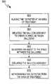
- FIGS. 4A-4EThe treatment process is further illustrated in FIGS. 4A-4E .
- the multi-function catheter 100is advanced to the treatment site so that the balloon assembly 108 is located right inside the area of the plaque 208 .
- the balloon assembly 108is then inflated to a first stage to form a chamber 204 around the plaque 208 ( FIG. 4B ).
- a plaque removal agentis then delivered within the chamber 204 .
- the plaque removal agentcan be forced into the plaque by the application of pressure through the fluid delivery conduit 110 (shown in FIG. 2A ) or by the expansion of the central balloon element 126 , as discussed in more details hereinabove.
- the plaque removal agentcan also be recirculated into the chamber 204 until the plaque (mostly cholesterol) is dissolved.
Landscapes
- Health & Medical Sciences (AREA)
- Heart & Thoracic Surgery (AREA)
- Life Sciences & Earth Sciences (AREA)
- Biomedical Technology (AREA)
- Engineering & Computer Science (AREA)
- Veterinary Medicine (AREA)
- Public Health (AREA)
- General Health & Medical Sciences (AREA)
- Animal Behavior & Ethology (AREA)
- Hematology (AREA)
- Anesthesiology (AREA)
- Pulmonology (AREA)
- Biophysics (AREA)
- Child & Adolescent Psychology (AREA)
- Vascular Medicine (AREA)
- Cardiology (AREA)
- Oral & Maxillofacial Surgery (AREA)
- Transplantation (AREA)
- Materials For Medical Uses (AREA)
- Media Introduction/Drainage Providing Device (AREA)
Abstract
Description
Claims (13)
Priority Applications (1)
| Application Number | Priority Date | Filing Date | Title |
|---|---|---|---|
| US12/405,592US8251948B2 (en) | 2002-02-01 | 2009-03-17 | Multi-function catheter and use thereof |
Applications Claiming Priority (6)
| Application Number | Priority Date | Filing Date | Title |
|---|---|---|---|
| US35330502P | 2002-02-01 | 2002-02-01 | |
| US38726002P | 2002-06-07 | 2002-06-07 | |
| US10/355,017US7645259B2 (en) | 2002-02-01 | 2003-01-31 | Multi-function catheter and use thereof |
| US11/097,582US20050267407A1 (en) | 2002-02-01 | 2005-04-01 | Multi-function catheter and use thereof |
| US11/971,859US8062251B2 (en) | 2002-02-01 | 2008-01-09 | Multi-function catheter and use thereof |
| US12/405,592US8251948B2 (en) | 2002-02-01 | 2009-03-17 | Multi-function catheter and use thereof |
Related Parent Applications (1)
| Application Number | Title | Priority Date | Filing Date |
|---|---|---|---|
| US11/971,859DivisionUS8062251B2 (en) | 2002-02-01 | 2008-01-09 | Multi-function catheter and use thereof |
Publications (2)
| Publication Number | Publication Date |
|---|---|
| US20090182227A1 US20090182227A1 (en) | 2009-07-16 |
| US8251948B2true US8251948B2 (en) | 2012-08-28 |
Family
ID=40853452
Family Applications (2)
| Application Number | Title | Priority Date | Filing Date |
|---|---|---|---|
| US11/971,859Expired - Fee RelatedUS8062251B2 (en) | 2002-02-01 | 2008-01-09 | Multi-function catheter and use thereof |
| US12/405,592Expired - Fee RelatedUS8251948B2 (en) | 2002-02-01 | 2009-03-17 | Multi-function catheter and use thereof |
Family Applications Before (1)
| Application Number | Title | Priority Date | Filing Date |
|---|---|---|---|
| US11/971,859Expired - Fee RelatedUS8062251B2 (en) | 2002-02-01 | 2008-01-09 | Multi-function catheter and use thereof |
Country Status (5)
| Country | Link |
|---|---|
| US (2) | US8062251B2 (en) |
| EP (1) | EP2240231A4 (en) |
| JP (1) | JP2011509158A (en) |
| CA (1) | CA2711739A1 (en) |
| WO (1) | WO2009089343A1 (en) |
Cited By (21)
| Publication number | Priority date | Publication date | Assignee | Title |
|---|---|---|---|---|
| US8821476B2 (en) | 2009-12-02 | 2014-09-02 | Renovorx, Inc. | Devices, methods and kits for delivery of therapeutic materials to a pancreas |
| US9457171B2 (en) | 2009-12-02 | 2016-10-04 | Renovorx, Inc. | Devices, methods and kits for delivery of therapeutic materials to a target artery |
| US10099040B2 (en) | 2013-06-03 | 2018-10-16 | Renovorx, Inc. | Occlusion catheter system and methods of use |
| US10398441B2 (en) | 2013-12-20 | 2019-09-03 | Terumo Corporation | Vascular occlusion |
| US10512761B2 (en) | 2009-12-02 | 2019-12-24 | Renovorx, Inc. | Methods for delivery of therapeutic materials to treat pancreatic cancer |
| US10588636B2 (en) | 2017-03-20 | 2020-03-17 | Surefire Medical, Inc. | Dynamic reconfigurable microvalve protection device |
| US10695543B2 (en) | 2017-05-18 | 2020-06-30 | Renovorx, Inc. | Methods for treating cancerous tumors |
| US10780250B1 (en) | 2016-09-19 | 2020-09-22 | Surefire Medical, Inc. | System and method for selective pressure-controlled therapeutic delivery |
| US10813739B2 (en) | 2009-12-02 | 2020-10-27 | Surefire Medical, Inc. | Dynamic microvalve protection device |
| US11052224B2 (en) | 2017-05-18 | 2021-07-06 | Renovorx, Inc. | Methods for treating cancerous tumors |
| US11090460B2 (en) | 2015-03-31 | 2021-08-17 | Surefire Medical, Inc. | Method for infusing an immunotherapy agent to a solid tumor for treatment |
| US11135361B2 (en) | 2014-03-25 | 2021-10-05 | Surefire Medical, Inc. | Closed tip dynamic microvalve protection device |
| US11338117B2 (en) | 2018-10-08 | 2022-05-24 | Trisalus Life Sciences, Inc. | Implantable dual pathway therapeutic agent delivery port |
| US11400263B1 (en) | 2016-09-19 | 2022-08-02 | Trisalus Life Sciences, Inc. | System and method for selective pressure-controlled therapeutic delivery |
| US11564692B2 (en) | 2018-11-01 | 2023-01-31 | Terumo Corporation | Occlusion systems |
| US11850398B2 (en) | 2018-08-01 | 2023-12-26 | Trisalus Life Sciences, Inc. | Systems and methods for pressure-facilitated therapeutic agent delivery |
| US12011174B2 (en) | 2020-04-28 | 2024-06-18 | Terumo Corporation | Occlusion systems |
| US12023035B2 (en) | 2017-05-25 | 2024-07-02 | Terumo Corporation | Adhesive occlusion systems |
| US12156980B2 (en) | 2019-08-26 | 2024-12-03 | Boston Scientific Scimed, Inc. | Devices, systems, and methods for a catheter accessory |
| US12290564B2 (en) | 2017-05-18 | 2025-05-06 | Renovorx, Inc. | Methods and apparatuses for treating tumors |
| US12433597B2 (en) | 2019-06-04 | 2025-10-07 | Trisalus Life Sciences, Inc. | Atraumatic occlusive system with compartment for measurement of vascular pressure change |
Families Citing this family (62)
| Publication number | Priority date | Publication date | Assignee | Title |
|---|---|---|---|---|
| US6863683B2 (en) | 2001-09-19 | 2005-03-08 | Abbott Laboratoris Vascular Entities Limited | Cold-molding process for loading a stent onto a stent delivery system |
| US8062251B2 (en)* | 2002-02-01 | 2011-11-22 | Vascular Designs, Inc. | Multi-function catheter and use thereof |
| EP1469902A4 (en)* | 2002-02-01 | 2006-08-23 | Robert J Goldman | Multi-function catheter and use thereof |
| US20050267407A1 (en)* | 2002-02-01 | 2005-12-01 | Vascular Designs, Inc. | Multi-function catheter and use thereof |
| US8333000B2 (en) | 2006-06-19 | 2012-12-18 | Advanced Cardiovascular Systems, Inc. | Methods for improving stent retention on a balloon catheter |
| US20090187211A1 (en)* | 2007-12-21 | 2009-07-23 | Abbott Laboratories | Vena cava filter having hourglass shape |
| CN102271747B (en) | 2008-11-03 | 2014-06-04 | 先端导管治疗公司 | occlusive perfusion catheter |
| US8226601B2 (en) | 2008-11-12 | 2012-07-24 | Sanovas, Inc. | Resector balloon system |
| US8540667B2 (en)* | 2008-11-12 | 2013-09-24 | Sanovas, Inc. | Multi-balloon catheter for extravasated drug delivery |
| EP2668934B1 (en) | 2008-12-12 | 2017-05-10 | Abbott Laboratories Vascular Enterprises Limited | Process for loading a stent onto a stent delivery system |
| US20110106234A1 (en)* | 2009-10-30 | 2011-05-05 | Axel Grandt | Interluminal medical treatment devices and methods |
| EP2322118B1 (en)* | 2009-11-11 | 2012-12-19 | Abbott Laboratories Vascular Enterprises Limited | Medical devices for medical device delivery systems |
| WO2011050979A1 (en)* | 2009-10-30 | 2011-05-05 | Abbott Laboratories Vascular Enterprises Limited | Medical devices for medical device delivery systems |
| US8597239B2 (en)* | 2011-03-01 | 2013-12-03 | Sanovas, Inc. | Abrading balloon catheter for extravasated drug delivery |
| US10898693B2 (en) | 2011-03-01 | 2021-01-26 | Sanovas Intellectual Property, Llc | Nasal delivery of agents with nested balloon catheter |
| US8348890B2 (en) | 2011-03-01 | 2013-01-08 | Sanovas, Inc. | Nested balloon catheter for localized drug delivery |
| US20160074581A1 (en) | 2014-09-17 | 2016-03-17 | Lawrence J. Gerrans | Modulated Drug Delivery |
| US20120259401A1 (en) | 2011-04-08 | 2012-10-11 | Gerrans Lawrence J | Balloon catheter for launching drug delivery device |
| US9180281B2 (en) | 2011-04-08 | 2015-11-10 | Sanovas, Inc. | Adjustable balloon catheter for extravasated drug delivery |
| US9205234B2 (en) | 2012-03-27 | 2015-12-08 | Terry D. Hardin | Device for a biological treatment |
| CA2881462C (en) | 2012-08-09 | 2020-07-14 | University Of Iowa Research Foundation | Catheters, catheter systems, and methods for puncturing through a tissue structure |
| EP4464374A3 (en)* | 2012-11-02 | 2025-01-15 | Neurotronic, Inc. | Chemical ablation formulations for various diseases |
| US12208224B2 (en) | 2012-11-02 | 2025-01-28 | Neurotronic, Inc. | Chemical ablation and method of treatment for various diseases |
| US9205226B2 (en) | 2013-05-08 | 2015-12-08 | Embolx, Inc. | Device and methods for transvascular tumor embolization with integrated flow regulation |
| US9844383B2 (en) | 2013-05-08 | 2017-12-19 | Embolx, Inc. | Devices and methods for low pressure tumor embolization |
| EP3091921B1 (en) | 2014-01-06 | 2019-06-19 | Farapulse, Inc. | Apparatus for renal denervation ablation |
| EP3495018B1 (en) | 2014-05-07 | 2023-09-06 | Farapulse, Inc. | Apparatus for selective tissue ablation |
| WO2015175944A1 (en) | 2014-05-16 | 2015-11-19 | Gary Long | Methods and apparatus for multi-catheter tissue ablation |
| EP3154463B1 (en) | 2014-06-12 | 2019-03-27 | Farapulse, Inc. | Apparatus for rapid and selective transurethral tissue ablation |
| WO2015192018A1 (en) | 2014-06-12 | 2015-12-17 | Iowa Approach Inc. | Method and apparatus for rapid and selective tissue ablation with cooling |
| EP3206613B1 (en) | 2014-10-14 | 2019-07-03 | Farapulse, Inc. | Apparatus for rapid and safe pulmonary vein cardiac ablation |
| US10286191B2 (en) | 2014-10-30 | 2019-05-14 | Neurotronic, Inc. | Chemical ablation and method of treatment for various diseases |
| US10660702B2 (en) | 2016-01-05 | 2020-05-26 | Farapulse, Inc. | Systems, devices, and methods for focal ablation |
| US10172673B2 (en) | 2016-01-05 | 2019-01-08 | Farapulse, Inc. | Systems devices, and methods for delivery of pulsed electric field ablative energy to endocardial tissue |
| US12144541B2 (en) | 2016-01-05 | 2024-11-19 | Boston Scientific Scimed, Inc. | Systems, apparatuses and methods for delivery of ablative energy to tissue |
| US10130423B1 (en) | 2017-07-06 | 2018-11-20 | Farapulse, Inc. | Systems, devices, and methods for focal ablation |
| US20170189097A1 (en) | 2016-01-05 | 2017-07-06 | Iowa Approach Inc. | Systems, apparatuses and methods for delivery of ablative energy to tissue |
| US12268824B2 (en) | 2018-07-27 | 2025-04-08 | Embolx, Inc. | Shaped catheter tip for tracking over a guidewire through turns in the vasculature |
| US10350382B1 (en) | 2018-06-08 | 2019-07-16 | Embolx, Inc. | High torque catheter and methods of manufacture |
| US11464948B2 (en) | 2016-02-16 | 2022-10-11 | Embolx, Inc. | Balloon catheters and methods of manufacture and use |
| US9550046B1 (en) | 2016-02-16 | 2017-01-24 | Embolx, Inc. | Balloon catheter and methods of fabrication and use |
| US10588503B2 (en) | 2016-03-29 | 2020-03-17 | Terumo Kabushiki Kaisha | Methods and medical elongate bodies |
| EP3471631A4 (en) | 2016-06-16 | 2020-03-04 | Farapulse, Inc. | GUIDE WIRE DISTRIBUTION SYSTEMS, APPARATUSES AND METHODS |
| US9987081B1 (en) | 2017-04-27 | 2018-06-05 | Iowa Approach, Inc. | Systems, devices, and methods for signal generation |
| US10617867B2 (en) | 2017-04-28 | 2020-04-14 | Farapulse, Inc. | Systems, devices, and methods for delivery of pulsed electric field ablative energy to esophageal tissue |
| JP7586706B2 (en) | 2017-09-12 | 2024-11-19 | ボストン サイエンティフィック サイムド,インコーポレイテッド | Systems, devices and methods for focal ventricular ablation - Patents.com |
| JP2019097596A (en)* | 2017-11-28 | 2019-06-24 | 株式会社カネカ | Balloon catheter |
| EP3749238B1 (en) | 2018-02-08 | 2023-08-16 | Farapulse, Inc. | Apparatus for controlled delivery of pulsed electric field ablative energy to tissue |
| US20190336198A1 (en) | 2018-05-03 | 2019-11-07 | Farapulse, Inc. | Systems, devices, and methods for ablation using surgical clamps |
| CN112087978B (en) | 2018-05-07 | 2023-01-17 | 波士顿科学医学有限公司 | epicardial ablation catheter |
| WO2019217433A1 (en) | 2018-05-07 | 2019-11-14 | Farapulse, Inc. | Systems, apparatuses and methods for delivery of ablative energy to tissue |
| CN119074196A (en) | 2018-05-07 | 2024-12-06 | 波士顿科学医学有限公司 | Systems, devices and methods for filtering high voltage noise induced by pulsed electric field ablation |
| US10687892B2 (en) | 2018-09-20 | 2020-06-23 | Farapulse, Inc. | Systems, apparatuses, and methods for delivery of pulsed electric field ablative energy to endocardial tissue |
| US12409298B2 (en) | 2019-08-20 | 2025-09-09 | Embolx, Inc. | Catheters and methods of manufacture and use |
| US10625080B1 (en) | 2019-09-17 | 2020-04-21 | Farapulse, Inc. | Systems, apparatuses, and methods for detecting ectopic electrocardiogram signals during pulsed electric field ablation |
| US11497541B2 (en) | 2019-11-20 | 2022-11-15 | Boston Scientific Scimed, Inc. | Systems, apparatuses, and methods for protecting electronic components from high power noise induced by high voltage pulses |
| US11065047B2 (en) | 2019-11-20 | 2021-07-20 | Farapulse, Inc. | Systems, apparatuses, and methods for protecting electronic components from high power noise induced by high voltage pulses |
| US10842572B1 (en) | 2019-11-25 | 2020-11-24 | Farapulse, Inc. | Methods, systems, and apparatuses for tracking ablation devices and generating lesion lines |
| US12310652B2 (en) | 2020-07-24 | 2025-05-27 | Boston Scientific Scimed, Inc. | Hybrid electroporation ablation catheter |
| WO2022020478A1 (en) | 2020-07-24 | 2022-01-27 | Boston Scientific Scimed Inc | Electric field application for single shot cardiac ablation by irreversible electroporation |
| WO2022072385A2 (en) | 2020-09-30 | 2022-04-07 | Boston Scientific Scimed Inc | Pretreatment waveform for irreversible electroporation |
| JP2024504184A (en) | 2021-01-27 | 2024-01-30 | ボストン サイエンティフィック サイムド,インコーポレイテッド | Voltage-controlled pulse sequence for irreversible electroporation ablation |
Citations (82)
| Publication number | Priority date | Publication date | Assignee | Title |
|---|---|---|---|---|
| US4573966A (en)* | 1981-11-24 | 1986-03-04 | Schneider Medintag Ag | Method and apparatus for removing and/or enlarging constricted areas in vessels conducting body fluids |
| US4636195A (en) | 1982-04-02 | 1987-01-13 | Harvey Wolinsky | Method and apparatus for removing arterial constriction |
| US4655746A (en) | 1985-12-02 | 1987-04-07 | Target Therapeutics | Catheter device |
| US4696668A (en)* | 1985-07-17 | 1987-09-29 | Wilcox Gilbert M | Double balloon nasobiliary occlusion catheter for treating gallstones and method of using the same |
| US4708718A (en) | 1985-07-02 | 1987-11-24 | Target Therapeutics | Hyperthermic treatment of tumors |
| US4714460A (en)* | 1983-07-29 | 1987-12-22 | Reynaldo Calderon | Methods and systems for retrograde perfusion in the body for curing it of the disease or immume deficiency |
| US4824436A (en)* | 1985-04-09 | 1989-04-25 | Harvey Wolinsky | Method for the prevention of restenosis |
| US4832688A (en)* | 1986-04-09 | 1989-05-23 | Terumo Kabushiki Kaisha | Catheter for repair of blood vessel |
| US5090960A (en) | 1990-01-12 | 1992-02-25 | Don Michael T Anthony | Regional perfusion dissolution catheter |
| US5160321A (en) | 1988-11-23 | 1992-11-03 | Harvinder Sahota | Balloon catheters |
| US5163905A (en) | 1990-01-12 | 1992-11-17 | Don Michael T Anthony | Regional perfusion dissolution catheter |
| US5176638A (en) | 1990-01-12 | 1993-01-05 | Don Michael T Anthony | Regional perfusion catheter with improved drug delivery control |
| US5222941A (en) | 1990-01-12 | 1993-06-29 | Don Michael T Anthony | Method of dissolving an obstruction in a vessel |
| US5257634A (en) | 1992-07-16 | 1993-11-02 | Angeion Corporation | Low impedence defibrillation catheter electrode |
| US5265623A (en) | 1992-07-16 | 1993-11-30 | Angeion Corporation | Optimized field defibrillation catheter |
| US5330509A (en) | 1992-04-06 | 1994-07-19 | Angeion Corporation | Method and apparatus for far-field tachycardia termination |
| US5409495A (en) | 1993-08-24 | 1995-04-25 | Advanced Cardiovascular Systems, Inc. | Apparatus for uniformly implanting a stent |
| US5415636A (en)* | 1994-04-13 | 1995-05-16 | Schneider (Usa) Inc | Dilation-drug delivery catheter |
| US5423744A (en) | 1992-12-22 | 1995-06-13 | Gencheff; Nelson | Catheter system for the deployment of biological material |
| US5439446A (en) | 1994-06-30 | 1995-08-08 | Boston Scientific Corporation | Stent and therapeutic delivery system |
| US5454839A (en) | 1992-07-27 | 1995-10-03 | Angeion Corporation | Low profile defibrillation catheter |
| US5460610A (en) | 1990-01-12 | 1995-10-24 | Don Michael; T. Anthony | Treatment of obstructions in body passages |
| US5462529A (en) | 1993-09-29 | 1995-10-31 | Technology Development Center | Adjustable treatment chamber catheter |
| US5470313A (en) | 1994-02-24 | 1995-11-28 | Cardiovascular Dynamics, Inc. | Variable diameter balloon dilatation catheter |
| US5514092A (en)* | 1994-08-08 | 1996-05-07 | Schneider (Usa) Inc. | Drug delivery and dilatation-drug delivery catheters in a rapid exchange configuration |
| US5516336A (en) | 1990-02-07 | 1996-05-14 | Advanced Cardiovascular Systems, Inc. | Readily exchangeable perfusion dilatation catheter |
| US5554119A (en) | 1991-08-02 | 1996-09-10 | Scimed | Drug delivery catheter with manifold |
| US5569197A (en) | 1994-12-21 | 1996-10-29 | Schneider (Usa) Inc | Drug delivery guidewire |
| US5628730A (en) | 1990-06-15 | 1997-05-13 | Cortrak Medical, Inc. | Phoretic balloon catheter with hydrogel coating |
| WO1997024154A1 (en) | 1995-12-28 | 1997-07-10 | Cordis Corporation | Multipurpose balloon catheter |
| US5649974A (en) | 1992-07-27 | 1997-07-22 | Angeion Corporation | Low profile defibrillation catheter |
| US5662609A (en) | 1990-02-26 | 1997-09-02 | Endoluminal Therapeutics, Inc. | Method and apparatus for treatment of focal disease in hollow tubular organs and other tissue lumens |
| US5674198A (en) | 1995-06-23 | 1997-10-07 | Cordis Corporation | Tandem balloon catheter |
| US5713944A (en) | 1996-02-13 | 1998-02-03 | Angeion Corporation | Cardioversion-defibrillation catheter lead having selectively exposable outer conductors |
| US5792106A (en) | 1993-12-02 | 1998-08-11 | Scimed Life Systems, Inc. | In situ stent forming catheter |
| WO1998048884A2 (en) | 1997-05-01 | 1998-11-05 | Chase Medical Inc. | Aortic arch occlusion and perfusion balloon catheter having pressure ports |
| US5868719A (en) | 1997-01-15 | 1999-02-09 | Boston Scientific Corporation | Drug delivery balloon catheter device |
| US5899917A (en) | 1997-03-12 | 1999-05-04 | Cardiosynopsis, Inc. | Method for forming a stent in situ |
| EP0920882A2 (en) | 1997-12-04 | 1999-06-09 | Schneider Inc. | Balloon dilatation-drug delivery catheter and stent deployment-drug delivery catheter in rapid exchange configuration |
| US5925066A (en) | 1995-10-26 | 1999-07-20 | Galvani, Ltd. | Atrial arrythmia sensor with drug and electrical therapy control apparatus |
| US6015414A (en) | 1997-08-29 | 2000-01-18 | Stereotaxis, Inc. | Method and apparatus for magnetically controlling motion direction of a mechanically pushed catheter |
| US6022336A (en) | 1996-05-20 | 2000-02-08 | Percusurge, Inc. | Catheter system for emboli containment |
| US6027510A (en) | 1997-12-08 | 2000-02-22 | Inflow Dynamics Inc. | Stent delivery system |
| US6056721A (en) | 1997-08-08 | 2000-05-02 | Sunscope International, Inc. | Balloon catheter and method |
| US6132426A (en) | 1998-05-05 | 2000-10-17 | Daig Corporation | Temperature and current limited ablation catheter |
| US6136011A (en) | 1998-07-14 | 2000-10-24 | Advanced Cardiovascular Systems, Inc. | Stent delivery system and method of use |
| US6139517A (en) | 1997-12-15 | 2000-10-31 | Cardeon Corporation | Perfusion shunt apparatus and method |
| US6171296B1 (en) | 1998-04-28 | 2001-01-09 | Microtherapeutics, Inc. | Flow directed catheter |
| US6214022B1 (en) | 1996-02-20 | 2001-04-10 | Cardiothoracic Systems, Inc. | Perfusion device for maintaining blood flow in a vessel while isolating an anastomosis |
| US6231562B1 (en) | 1995-07-19 | 2001-05-15 | Endotex Interventional Systems, Inc. | Methods and apparatus for treating aneurysms and arterio-venous fistulas |
| US6231588B1 (en) | 1998-08-04 | 2001-05-15 | Percusurge, Inc. | Low profile catheter for angioplasty and occlusion |
| US6254563B1 (en) | 1997-12-15 | 2001-07-03 | Cardeon Corporation | Perfusion shunt apparatus and method |
| US6287306B1 (en) | 1998-06-22 | 2001-09-11 | Daig Corporation | Even temperature linear lesion ablation catheter |
| US6290689B1 (en) | 1999-10-22 | 2001-09-18 | Corazón Technologies, Inc. | Catheter devices and methods for their use in the treatment of calcified vascular occlusions |
| US6290673B1 (en) | 1999-05-20 | 2001-09-18 | Conor Medsystems, Inc. | Expandable medical device delivery system and method |
| US6291582B1 (en) | 1996-10-10 | 2001-09-18 | Biotechnology Research & Development Corp. | Polymer-protein composites and methods for their preparation and use |
| US6290485B1 (en) | 1995-03-02 | 2001-09-18 | Lixiao Wang | Mold for forming a balloon catheter having stepped compliance curve |
| US6299597B1 (en)* | 1993-09-16 | 2001-10-09 | Scimed Life Systems, Inc. | Percutaneous repair of cardiovascular anomalies and repair compositions |
| US6299599B1 (en)* | 1999-02-19 | 2001-10-09 | Alsius Corporation | Dual balloon central venous line catheter temperature control system |
| US20010036451A1 (en) | 2000-03-13 | 2001-11-01 | Goupil Dennis W. | Embolic compositions |
| US20010041862A1 (en)* | 1997-09-02 | 2001-11-15 | Morton G. Glickman | Novel apparatus and method of treating a tumor in the extremity of a patient |
| US6344041B1 (en) | 1996-07-26 | 2002-02-05 | David Kupiecki | Aneurysm closure device assembly |
| US6366808B1 (en) | 2000-03-13 | 2002-04-02 | Edward A. Schroeppel | Implantable device and method for the electrical treatment of cancer |
| JP2002102354A (en) | 2000-09-29 | 2002-04-09 | Create Medic Co Ltd | Balloon catheter |
| US6409716B1 (en) | 1989-12-15 | 2002-06-25 | Scimed Life Systems, Inc. | Drug delivery |
| US6428558B1 (en) | 1999-03-10 | 2002-08-06 | Cordis Corporation | Aneurysm embolization device |
| US6438426B2 (en) | 1998-12-30 | 2002-08-20 | Daig Corporation | Temporary atrial cardioversion catheter |
| US20030036726A1 (en) | 2000-12-19 | 2003-02-20 | Forman Michael Robert | Intra-pericardial drug delivery device for angiogenesis |
| US20030114878A1 (en)* | 2001-12-14 | 2003-06-19 | The Regents Of The University Of California | Catheter based balloon for therapy modification and positioning of tissue |
| US6582448B1 (en) | 2000-12-21 | 2003-06-24 | Advanced Cardiovascular Systems, Inc. | Vessel occlusion device for embolic protection system |
| WO2003065872A2 (en) | 2002-02-01 | 2003-08-14 | Goldman Robert J | Multi-function catheter and use thereof |
| US6679879B2 (en) | 2000-08-16 | 2004-01-20 | John H. Shadduck | Electrical discharge catheter system for extracting emboli in endovascular interventions |
| US6695864B2 (en) | 1997-12-15 | 2004-02-24 | Cardeon Corporation | Method and apparatus for cerebral embolic protection |
| US6738663B2 (en) | 1999-04-09 | 2004-05-18 | Oncostim, A Minnesota Corporation | Implantable device and method for the electrical treatment of cancer |
| US6835189B2 (en) | 2002-10-15 | 2004-12-28 | Scimed Life Systems, Inc. | Controlled deployment balloon |
| US20050267407A1 (en) | 2002-02-01 | 2005-12-01 | Vascular Designs, Inc. | Multi-function catheter and use thereof |
| US7144407B1 (en) | 2002-05-30 | 2006-12-05 | Alsius Corporation | Cardiovascular intra aortic balloon pump catheter with heat exchange function and methods of use |
| US20070137651A1 (en)* | 2005-12-16 | 2007-06-21 | Ezc Medical Llc | Visualization esophageal-tracheal airway apparatus and methods |
| US7412285B2 (en) | 1999-04-09 | 2008-08-12 | Oncostim, Inc. | Method and device for treating cancer with electrical therapy in conjunction with chemotherapeutic agents and radiation therapy |
| US20080208118A1 (en) | 2002-02-01 | 2008-08-28 | Vascular Designs, Inc. | Multi-function catheter and use thereof |
| US7481800B2 (en)* | 2000-02-04 | 2009-01-27 | Conmed Endoscopic Technologies | Triple lumen stone balloon catheter and method |
| US7742811B2 (en) | 2000-03-13 | 2010-06-22 | Onco Stim | Implantable device and method for the electrical treatment of cancer |
Family Cites Families (2)
| Publication number | Priority date | Publication date | Assignee | Title |
|---|---|---|---|---|
| US267407A (en)* | 1882-11-14 | Return-flue vertical boiler | ||
| US5599307A (en)* | 1993-07-26 | 1997-02-04 | Loyola University Of Chicago | Catheter and method for the prevention and/or treatment of stenotic processes of vessels and cavities |
- 2008
- 2008-01-09USUS11/971,859patent/US8062251B2/ennot_activeExpired - Fee Related
- 2009
- 2009-01-08WOPCT/US2009/030434patent/WO2009089343A1/enactiveApplication Filing
- 2009-01-08EPEP09701443.5Apatent/EP2240231A4/ennot_activeWithdrawn
- 2009-01-08JPJP2010542338Apatent/JP2011509158A/enactivePending
- 2009-01-08CACA2711739Apatent/CA2711739A1/ennot_activeAbandoned
- 2009-03-17USUS12/405,592patent/US8251948B2/ennot_activeExpired - Fee Related
Patent Citations (93)
| Publication number | Priority date | Publication date | Assignee | Title |
|---|---|---|---|---|
| US4573966A (en)* | 1981-11-24 | 1986-03-04 | Schneider Medintag Ag | Method and apparatus for removing and/or enlarging constricted areas in vessels conducting body fluids |
| US4610662A (en)* | 1981-11-24 | 1986-09-09 | Schneider Medintag Ag | Method for the elimination or the enlargement of points of constriction in vessels carrying body fluids |
| US4636195A (en) | 1982-04-02 | 1987-01-13 | Harvey Wolinsky | Method and apparatus for removing arterial constriction |
| US4714460A (en)* | 1983-07-29 | 1987-12-22 | Reynaldo Calderon | Methods and systems for retrograde perfusion in the body for curing it of the disease or immume deficiency |
| US4824436A (en)* | 1985-04-09 | 1989-04-25 | Harvey Wolinsky | Method for the prevention of restenosis |
| US4708718A (en) | 1985-07-02 | 1987-11-24 | Target Therapeutics | Hyperthermic treatment of tumors |
| US4696668A (en)* | 1985-07-17 | 1987-09-29 | Wilcox Gilbert M | Double balloon nasobiliary occlusion catheter for treating gallstones and method of using the same |
| US4655746A (en) | 1985-12-02 | 1987-04-07 | Target Therapeutics | Catheter device |
| US4832688A (en)* | 1986-04-09 | 1989-05-23 | Terumo Kabushiki Kaisha | Catheter for repair of blood vessel |
| US5160321A (en) | 1988-11-23 | 1992-11-03 | Harvinder Sahota | Balloon catheters |
| US6409716B1 (en) | 1989-12-15 | 2002-06-25 | Scimed Life Systems, Inc. | Drug delivery |
| US5460610A (en) | 1990-01-12 | 1995-10-24 | Don Michael; T. Anthony | Treatment of obstructions in body passages |
| US5163905A (en) | 1990-01-12 | 1992-11-17 | Don Michael T Anthony | Regional perfusion dissolution catheter |
| US5176638A (en) | 1990-01-12 | 1993-01-05 | Don Michael T Anthony | Regional perfusion catheter with improved drug delivery control |
| US5222941A (en) | 1990-01-12 | 1993-06-29 | Don Michael T Anthony | Method of dissolving an obstruction in a vessel |
| US5090960A (en) | 1990-01-12 | 1992-02-25 | Don Michael T Anthony | Regional perfusion dissolution catheter |
| US5516336A (en) | 1990-02-07 | 1996-05-14 | Advanced Cardiovascular Systems, Inc. | Readily exchangeable perfusion dilatation catheter |
| US5662609A (en) | 1990-02-26 | 1997-09-02 | Endoluminal Therapeutics, Inc. | Method and apparatus for treatment of focal disease in hollow tubular organs and other tissue lumens |
| US6287320B1 (en)* | 1990-02-26 | 2001-09-11 | Endoluminal Therapeutics, Inc. | Method and apparatus for treatment of focal disease in hollow tubular organs and other tissue lumens |
| US5628730A (en) | 1990-06-15 | 1997-05-13 | Cortrak Medical, Inc. | Phoretic balloon catheter with hydrogel coating |
| US5558642A (en) | 1991-08-02 | 1996-09-24 | Scimed Life Systems, Inc. | Drug delivery catheter |
| US5554119A (en) | 1991-08-02 | 1996-09-10 | Scimed | Drug delivery catheter with manifold |
| US5330509A (en) | 1992-04-06 | 1994-07-19 | Angeion Corporation | Method and apparatus for far-field tachycardia termination |
| US5265623A (en) | 1992-07-16 | 1993-11-30 | Angeion Corporation | Optimized field defibrillation catheter |
| US5257634A (en) | 1992-07-16 | 1993-11-02 | Angeion Corporation | Low impedence defibrillation catheter electrode |
| US5454839A (en) | 1992-07-27 | 1995-10-03 | Angeion Corporation | Low profile defibrillation catheter |
| US5649974A (en) | 1992-07-27 | 1997-07-22 | Angeion Corporation | Low profile defibrillation catheter |
| US5423744A (en) | 1992-12-22 | 1995-06-13 | Gencheff; Nelson | Catheter system for the deployment of biological material |
| US5409495A (en) | 1993-08-24 | 1995-04-25 | Advanced Cardiovascular Systems, Inc. | Apparatus for uniformly implanting a stent |
| US6299597B1 (en)* | 1993-09-16 | 2001-10-09 | Scimed Life Systems, Inc. | Percutaneous repair of cardiovascular anomalies and repair compositions |
| US5462529A (en) | 1993-09-29 | 1995-10-31 | Technology Development Center | Adjustable treatment chamber catheter |
| US5792106A (en) | 1993-12-02 | 1998-08-11 | Scimed Life Systems, Inc. | In situ stent forming catheter |
| US5470313A (en) | 1994-02-24 | 1995-11-28 | Cardiovascular Dynamics, Inc. | Variable diameter balloon dilatation catheter |
| JPH0852219A (en) | 1994-02-24 | 1996-02-27 | Cardiovascular Dynamics Inc | Baloon catheter,multiple zone baloon catheter and method by using those |
| US5415636A (en)* | 1994-04-13 | 1995-05-16 | Schneider (Usa) Inc | Dilation-drug delivery catheter |
| US5439446A (en) | 1994-06-30 | 1995-08-08 | Boston Scientific Corporation | Stent and therapeutic delivery system |
| US5514092A (en)* | 1994-08-08 | 1996-05-07 | Schneider (Usa) Inc. | Drug delivery and dilatation-drug delivery catheters in a rapid exchange configuration |
| US5569197A (en) | 1994-12-21 | 1996-10-29 | Schneider (Usa) Inc | Drug delivery guidewire |
| US6290485B1 (en) | 1995-03-02 | 2001-09-18 | Lixiao Wang | Mold for forming a balloon catheter having stepped compliance curve |
| US5674198A (en) | 1995-06-23 | 1997-10-07 | Cordis Corporation | Tandem balloon catheter |
| US6231562B1 (en) | 1995-07-19 | 2001-05-15 | Endotex Interventional Systems, Inc. | Methods and apparatus for treating aneurysms and arterio-venous fistulas |
| US5925066A (en) | 1995-10-26 | 1999-07-20 | Galvani, Ltd. | Atrial arrythmia sensor with drug and electrical therapy control apparatus |
| WO1997024154A1 (en) | 1995-12-28 | 1997-07-10 | Cordis Corporation | Multipurpose balloon catheter |
| US5713944A (en) | 1996-02-13 | 1998-02-03 | Angeion Corporation | Cardioversion-defibrillation catheter lead having selectively exposable outer conductors |
| US6214022B1 (en) | 1996-02-20 | 2001-04-10 | Cardiothoracic Systems, Inc. | Perfusion device for maintaining blood flow in a vessel while isolating an anastomosis |
| US6022336A (en) | 1996-05-20 | 2000-02-08 | Percusurge, Inc. | Catheter system for emboli containment |
| US6344041B1 (en) | 1996-07-26 | 2002-02-05 | David Kupiecki | Aneurysm closure device assembly |
| US6291582B1 (en) | 1996-10-10 | 2001-09-18 | Biotechnology Research & Development Corp. | Polymer-protein composites and methods for their preparation and use |
| US5868719A (en) | 1997-01-15 | 1999-02-09 | Boston Scientific Corporation | Drug delivery balloon catheter device |
| US6039757A (en) | 1997-03-12 | 2000-03-21 | Cardiosynopsis, Inc. | In situ formed fenestrated stent |
| US5899917A (en) | 1997-03-12 | 1999-05-04 | Cardiosynopsis, Inc. | Method for forming a stent in situ |
| WO1998048884A2 (en) | 1997-05-01 | 1998-11-05 | Chase Medical Inc. | Aortic arch occlusion and perfusion balloon catheter having pressure ports |
| JP2000513625A (en) | 1997-05-01 | 2000-10-17 | チェース メディカル インコーポレイテッド | Aortic arch occlusion and perfusion balloon catheter with pressure port |
| US6056721A (en) | 1997-08-08 | 2000-05-02 | Sunscope International, Inc. | Balloon catheter and method |
| US6015414A (en) | 1997-08-29 | 2000-01-18 | Stereotaxis, Inc. | Method and apparatus for magnetically controlling motion direction of a mechanically pushed catheter |
| US20010041862A1 (en)* | 1997-09-02 | 2001-11-15 | Morton G. Glickman | Novel apparatus and method of treating a tumor in the extremity of a patient |
| JPH11178929A (en) | 1997-12-04 | 1999-07-06 | Schneider Usa Inc | Balloon expansion drug delivery catheter and stent deployment drug delivery catheter in rapid exchange configuration |
| EP0920882A2 (en) | 1997-12-04 | 1999-06-09 | Schneider Inc. | Balloon dilatation-drug delivery catheter and stent deployment-drug delivery catheter in rapid exchange configuration |
| US6027510A (en) | 1997-12-08 | 2000-02-22 | Inflow Dynamics Inc. | Stent delivery system |
| US6254563B1 (en) | 1997-12-15 | 2001-07-03 | Cardeon Corporation | Perfusion shunt apparatus and method |
| US6139517A (en) | 1997-12-15 | 2000-10-31 | Cardeon Corporation | Perfusion shunt apparatus and method |
| US6695864B2 (en) | 1997-12-15 | 2004-02-24 | Cardeon Corporation | Method and apparatus for cerebral embolic protection |
| US6171296B1 (en) | 1998-04-28 | 2001-01-09 | Microtherapeutics, Inc. | Flow directed catheter |
| US6132426A (en) | 1998-05-05 | 2000-10-17 | Daig Corporation | Temperature and current limited ablation catheter |
| US6287306B1 (en) | 1998-06-22 | 2001-09-11 | Daig Corporation | Even temperature linear lesion ablation catheter |
| US6780181B2 (en) | 1998-06-22 | 2004-08-24 | St. Jude Medical, Daig Division, Inc. | Even temperature linear lesion ablation catheter |
| US6136011A (en) | 1998-07-14 | 2000-10-24 | Advanced Cardiovascular Systems, Inc. | Stent delivery system and method of use |
| US6231588B1 (en) | 1998-08-04 | 2001-05-15 | Percusurge, Inc. | Low profile catheter for angioplasty and occlusion |
| US6438426B2 (en) | 1998-12-30 | 2002-08-20 | Daig Corporation | Temporary atrial cardioversion catheter |
| US6299599B1 (en)* | 1999-02-19 | 2001-10-09 | Alsius Corporation | Dual balloon central venous line catheter temperature control system |
| US6428558B1 (en) | 1999-03-10 | 2002-08-06 | Cordis Corporation | Aneurysm embolization device |
| US7412285B2 (en) | 1999-04-09 | 2008-08-12 | Oncostim, Inc. | Method and device for treating cancer with electrical therapy in conjunction with chemotherapeutic agents and radiation therapy |
| US6738663B2 (en) | 1999-04-09 | 2004-05-18 | Oncostim, A Minnesota Corporation | Implantable device and method for the electrical treatment of cancer |
| US6290673B1 (en) | 1999-05-20 | 2001-09-18 | Conor Medsystems, Inc. | Expandable medical device delivery system and method |
| US6290689B1 (en) | 1999-10-22 | 2001-09-18 | Corazón Technologies, Inc. | Catheter devices and methods for their use in the treatment of calcified vascular occlusions |
| US7481800B2 (en)* | 2000-02-04 | 2009-01-27 | Conmed Endoscopic Technologies | Triple lumen stone balloon catheter and method |
| US20010036451A1 (en) | 2000-03-13 | 2001-11-01 | Goupil Dennis W. | Embolic compositions |
| US7742811B2 (en) | 2000-03-13 | 2010-06-22 | Onco Stim | Implantable device and method for the electrical treatment of cancer |
| US6366808B1 (en) | 2000-03-13 | 2002-04-02 | Edward A. Schroeppel | Implantable device and method for the electrical treatment of cancer |
| US6679879B2 (en) | 2000-08-16 | 2004-01-20 | John H. Shadduck | Electrical discharge catheter system for extracting emboli in endovascular interventions |
| JP2002102354A (en) | 2000-09-29 | 2002-04-09 | Create Medic Co Ltd | Balloon catheter |
| US20030036726A1 (en) | 2000-12-19 | 2003-02-20 | Forman Michael Robert | Intra-pericardial drug delivery device for angiogenesis |
| US6582448B1 (en) | 2000-12-21 | 2003-06-24 | Advanced Cardiovascular Systems, Inc. | Vessel occlusion device for embolic protection system |
| US20030114878A1 (en)* | 2001-12-14 | 2003-06-19 | The Regents Of The University Of California | Catheter based balloon for therapy modification and positioning of tissue |
| US20050267407A1 (en) | 2002-02-01 | 2005-12-01 | Vascular Designs, Inc. | Multi-function catheter and use thereof |
| US20080208118A1 (en) | 2002-02-01 | 2008-08-28 | Vascular Designs, Inc. | Multi-function catheter and use thereof |
| US20090182227A1 (en) | 2002-02-01 | 2009-07-16 | Vascular Designs, Inc. | Multi-function catheter and use thereof |
| US7645259B2 (en) | 2002-02-01 | 2010-01-12 | Vascular Designs, Inc. | Multi-function catheter and use thereof |
| US20100114021A1 (en) | 2002-02-01 | 2010-05-06 | Vascular Designs, Inc. | Multi-function catheter and use thereof |
| WO2003065872A2 (en) | 2002-02-01 | 2003-08-14 | Goldman Robert J | Multi-function catheter and use thereof |
| US7144407B1 (en) | 2002-05-30 | 2006-12-05 | Alsius Corporation | Cardiovascular intra aortic balloon pump catheter with heat exchange function and methods of use |
| US6835189B2 (en) | 2002-10-15 | 2004-12-28 | Scimed Life Systems, Inc. | Controlled deployment balloon |
| US20070137651A1 (en)* | 2005-12-16 | 2007-06-21 | Ezc Medical Llc | Visualization esophageal-tracheal airway apparatus and methods |
Non-Patent Citations (20)
| Title |
|---|
| Cliffton, E.E. (May 1969). "Bronchial Artery Perfusion for Treatment of Advanced Lung Cancer," Cancer 23(5):1151-1157. |
| Cliffton, E.E. et al. (Apr. 1963). "Technique for Visualization and Perfusion of Bronchial Arteries: Suggested Clinical and Diagnostic Applications," Cancer 16(4):444-452. |
| Esler, M.D. et al. (Dec. 4, 2010, e-pub. Nov. 17, 2010). "Renal Sympathetic Denervation in Patients with Treatment-Resistant Hypertension (The Symplicity HTN-2 Trial): A Randomised Controlled Trial," Lancet 376(9756):1903-1909. |
| Final Office Action mailed on Aug. 18, 2010, for U.S. Appl. No. 11/097,582, filed Apr. 1, 2005, eight pages. |
| Final Office Action mailed on Jun. 24, 2010, for U.S. Appl. No. 11/971,859, filed Jan. 9, 2008, ten pages. |
| International Search Report mailed Oct. 30, 2003, for PCT Application No. PCT/US03/02755, filed Jan. 31, 2003, one page. |
| Non-Final Office Action mailed May 11, 2009, for U.S. Appl. No. 11/971,859, filed Jan. 9, 2008, nine pages. |
| Non-Final Office Action mailed on Feb. 15, 2011, for U.S. Appl. No. 11/971,859, filed Jan. 9, 2008, seven pages. |
| Non-Final Office Action mailed on Feb. 23, 2005, for U.S. Appl. No. 10/355,017, filed Jan. 31, 2003, six pages. |
| Non-Final Office Action mailed on Jul. 11, 2008, for U.S. Appl. No. 10/355,017, filed Jan. 31, 2003, seven pages. |
| Non-Final Office Action mailed on Jul. 30, 2007, for U.S. Appl. No. 10/355,017, filed Jan. 31, 2003, six pages. |
| Non-Final Office Action mailed on Jun. 14, 2010, for U.S. Appl. No. 12/685,533, filed Jan. 11, 2010, eight pages. |
| Non-Final Office Action mailed on Mar. 31, 2011, for U.S. Appl. No. 11/097,582, filed Apr. 1, 2005, six pages. |
| Non-Final Office Action mailed on Nov. 23, 2009, for U.S. Appl. No. 11/971,859, filed Jan. 9, 2008, seven pages. |
| Non-Final Office Action mailed on Nov. 27, 2009, for U.S. Appl. No. 11/097,582, filed Apr. 1, 2005, eight pages. |
| Non-Final Office Action mailed on Oct. 11, 2006, for U.S. Appl. No. 10/355,017, filed Jan. 31, 2003, six pages. |
| PCT/US2009/030434 International Search Report, dated Feb. 26, 2009. |
| PCT/US2009/030434 Written Opinion, dated Feb. 26, 2009. |
| Rousselot, L.M. et al. (Mar. 1, 1965). "Selective Concentration of Anticancer Drugs in the Liver: Hepatic-Artery Infusion and Induced Hepatic Outflow Block," JAMA 191(9):707-710. |
| Supplemental Partial European Search Report mailed Jul. 24, 2006, for EP Patent Application No. 03710793.5, filed Jan. 31, 2003, four pages. |
Cited By (29)
| Publication number | Priority date | Publication date | Assignee | Title |
|---|---|---|---|---|
| US12201508B2 (en) | 2009-12-02 | 2025-01-21 | Trisalus Life Sciences, Inc. | Dynamic microvalve protection device |
| US9457171B2 (en) | 2009-12-02 | 2016-10-04 | Renovorx, Inc. | Devices, methods and kits for delivery of therapeutic materials to a target artery |
| US9463304B2 (en) | 2009-12-02 | 2016-10-11 | Renovorx, Inc. | Devices, methods and kits for delivery of therapeutic materials to a pancreas |
| US8821476B2 (en) | 2009-12-02 | 2014-09-02 | Renovorx, Inc. | Devices, methods and kits for delivery of therapeutic materials to a pancreas |
| US11541211B2 (en) | 2009-12-02 | 2023-01-03 | Renovorx, Inc. | Methods for delivery of therapeutic materials to treat cancer |
| US10512761B2 (en) | 2009-12-02 | 2019-12-24 | Renovorx, Inc. | Methods for delivery of therapeutic materials to treat pancreatic cancer |
| US10813739B2 (en) | 2009-12-02 | 2020-10-27 | Surefire Medical, Inc. | Dynamic microvalve protection device |
| US10099040B2 (en) | 2013-06-03 | 2018-10-16 | Renovorx, Inc. | Occlusion catheter system and methods of use |
| US11832824B2 (en) | 2013-12-20 | 2023-12-05 | Terumo Corporation | Vascular occlusion |
| US10398441B2 (en) | 2013-12-20 | 2019-09-03 | Terumo Corporation | Vascular occlusion |
| US12138424B2 (en) | 2014-03-25 | 2024-11-12 | Trisalus Life Sciences, Inc. | Closed tip dynamic microvalve protection device |
| US11135361B2 (en) | 2014-03-25 | 2021-10-05 | Surefire Medical, Inc. | Closed tip dynamic microvalve protection device |
| US12377245B2 (en) | 2015-03-31 | 2025-08-05 | Trisalus Life Sciences, Inc. | Method of delivering a therapeutic agent to a solid tumor for treatment |
| US11090460B2 (en) | 2015-03-31 | 2021-08-17 | Surefire Medical, Inc. | Method for infusing an immunotherapy agent to a solid tumor for treatment |
| US11400263B1 (en) | 2016-09-19 | 2022-08-02 | Trisalus Life Sciences, Inc. | System and method for selective pressure-controlled therapeutic delivery |
| US10780250B1 (en) | 2016-09-19 | 2020-09-22 | Surefire Medical, Inc. | System and method for selective pressure-controlled therapeutic delivery |
| US10588636B2 (en) | 2017-03-20 | 2020-03-17 | Surefire Medical, Inc. | Dynamic reconfigurable microvalve protection device |
| US11052224B2 (en) | 2017-05-18 | 2021-07-06 | Renovorx, Inc. | Methods for treating cancerous tumors |
| US12290564B2 (en) | 2017-05-18 | 2025-05-06 | Renovorx, Inc. | Methods and apparatuses for treating tumors |
| US10695543B2 (en) | 2017-05-18 | 2020-06-30 | Renovorx, Inc. | Methods for treating cancerous tumors |
| US12023035B2 (en) | 2017-05-25 | 2024-07-02 | Terumo Corporation | Adhesive occlusion systems |
| US11850398B2 (en) | 2018-08-01 | 2023-12-26 | Trisalus Life Sciences, Inc. | Systems and methods for pressure-facilitated therapeutic agent delivery |
| US12226604B2 (en) | 2018-10-08 | 2025-02-18 | Trisalus Life Sciences, Inc. | Dual pathway therapeutic agent delivery |
| US11338117B2 (en) | 2018-10-08 | 2022-05-24 | Trisalus Life Sciences, Inc. | Implantable dual pathway therapeutic agent delivery port |
| US12290266B2 (en) | 2018-11-01 | 2025-05-06 | Terumo Corporation | Occlusion systems |
| US11564692B2 (en) | 2018-11-01 | 2023-01-31 | Terumo Corporation | Occlusion systems |
| US12433597B2 (en) | 2019-06-04 | 2025-10-07 | Trisalus Life Sciences, Inc. | Atraumatic occlusive system with compartment for measurement of vascular pressure change |
| US12156980B2 (en) | 2019-08-26 | 2024-12-03 | Boston Scientific Scimed, Inc. | Devices, systems, and methods for a catheter accessory |
| US12011174B2 (en) | 2020-04-28 | 2024-06-18 | Terumo Corporation | Occlusion systems |
Also Published As
| Publication number | Publication date |
|---|---|
| WO2009089343A1 (en) | 2009-07-16 |
| US20090182227A1 (en) | 2009-07-16 |
| JP2011509158A (en) | 2011-03-24 |
| EP2240231A1 (en) | 2010-10-20 |
| CA2711739A1 (en) | 2009-07-16 |
| EP2240231A4 (en) | 2013-06-05 |
| US20080208118A1 (en) | 2008-08-28 |
| US8062251B2 (en) | 2011-11-22 |
Similar Documents
| Publication | Publication Date | Title |
|---|---|---|
| US8251948B2 (en) | Multi-function catheter and use thereof | |
| US20050267407A1 (en) | Multi-function catheter and use thereof | |
| CA2476263C (en) | Multi-function catheter and use thereof | |
| JP2730702B2 (en) | Device for treating lesions in hollow vessels and other tissue lumens | |
| JP3697263B2 (en) | Stent and therapeutic delivery system | |
| US7090655B2 (en) | Replenishable stent and delivery system | |
| US5256141A (en) | Biological material deployment method and apparatus | |
| JP5073747B2 (en) | Catheter for cell administration | |
| US20150209560A1 (en) | Occlusion perfusion catheter | |
| EP1913882A1 (en) | Flexible and rigid catherer resector balloon | |
| JPH09504212A (en) | How to treat disorders in the body canal | |
| WO2009036118A1 (en) | Drug eluting balloon | |
| JP2022527295A (en) | Methods and devices for procedures related to intravascular grafts |
Legal Events
| Date | Code | Title | Description |
|---|---|---|---|
| AS | Assignment | Owner name:VASCULAR DESIGNS, INC.,CALIFORNIA Free format text:ASSIGNMENT OF ASSIGNORS INTEREST;ASSIGNOR:GOLDMAN, ROBERT;REEL/FRAME:024207/0705 Effective date:20080506 Owner name:VASCULAR DESIGNS, INC., CALIFORNIA Free format text:ASSIGNMENT OF ASSIGNORS INTEREST;ASSIGNOR:GOLDMAN, ROBERT;REEL/FRAME:024207/0705 Effective date:20080506 | |
| ZAAA | Notice of allowance and fees due | Free format text:ORIGINAL CODE: NOA | |
| ZAAB | Notice of allowance mailed | Free format text:ORIGINAL CODE: MN/=. | |
| STCF | Information on status: patent grant | Free format text:PATENTED CASE | |
| FEPP | Fee payment procedure | Free format text:PAYOR NUMBER ASSIGNED (ORIGINAL EVENT CODE: ASPN); ENTITY STATUS OF PATENT OWNER: SMALL ENTITY | |
| FEPP | Fee payment procedure | Free format text:PAYER NUMBER DE-ASSIGNED (ORIGINAL EVENT CODE: RMPN); ENTITY STATUS OF PATENT OWNER: SMALL ENTITY | |
| FPAY | Fee payment | Year of fee payment:4 | |
| FEPP | Fee payment procedure | Free format text:MAINTENANCE FEE REMINDER MAILED (ORIGINAL EVENT CODE: REM.); ENTITY STATUS OF PATENT OWNER: SMALL ENTITY | |
| FEPP | Fee payment procedure | Free format text:7.5 YR SURCHARGE - LATE PMT W/IN 6 MO, SMALL ENTITY (ORIGINAL EVENT CODE: M2555); ENTITY STATUS OF PATENT OWNER: SMALL ENTITY | |
| MAFP | Maintenance fee payment | Free format text:PAYMENT OF MAINTENANCE FEE, 8TH YR, SMALL ENTITY (ORIGINAL EVENT CODE: M2552); ENTITY STATUS OF PATENT OWNER: SMALL ENTITY Year of fee payment:8 | |
| AS | Assignment | Owner name:MERIT MEDICAL SYSTEMS, INC., UTAH Free format text:ASSIGNMENT OF ASSIGNORS INTEREST;ASSIGNOR:VASCULAR DESIGNS, INC.;REEL/FRAME:056350/0851 Effective date:20201001 | |
| FEPP | Fee payment procedure | Free format text:MAINTENANCE FEE REMINDER MAILED (ORIGINAL EVENT CODE: REM.); ENTITY STATUS OF PATENT OWNER: SMALL ENTITY | |
| LAPS | Lapse for failure to pay maintenance fees | Free format text:PATENT EXPIRED FOR FAILURE TO PAY MAINTENANCE FEES (ORIGINAL EVENT CODE: EXP.); ENTITY STATUS OF PATENT OWNER: SMALL ENTITY | |
| STCH | Information on status: patent discontinuation | Free format text:PATENT EXPIRED DUE TO NONPAYMENT OF MAINTENANCE FEES UNDER 37 CFR 1.362 | |
| FP | Lapsed due to failure to pay maintenance fee | Effective date:20240828 |